IST Amigo Project Deliverable D2.1 Specification of the Amigo Abstract Middleware Architecture Public

Welcome message from author
This document is posted to help you gain knowledge. Please leave a comment to let me know what you think about it! Share it to your friends and learn new things together.
Transcript
IST Amigo Project
Deliverable D2.1
Specification of the Amigo Abstract Middleware Architecture
Public

April 2005 Public
Project Number : IST-004182
Project Title : Amigo
Deliverable Type : Report
Deliverable Number : D2.1
Title of Deliverable : Specification of the Amigo Abstract Middleware Architecture
Nature of Deliverable : RE
Internal Document Number : Amigo_WP2_D2.1_v10 final.doc
Contractual Delivery Date : 28 February 2005
Actual Delivery Date : 11 April 2005
Contributing WPs : WP2
Editor : INRIA: Nikolaos Georgantas
Author(s) : INRIA: Sonia Ben Mokhtar, Yérom-David Bromberg, Nikolaos Georgantas, Valérie Issarny, Laurent Réveillère, Daniele Sacchetti, Ferda Tartanoglu
FT: Anne Gerodolle, Gilles Privat, Fano Ramparany, Mathieu Vallée
Ikerlan: Jorge Parra
IMS: Marco Ahler, Viktor Grinewitschus, Christian Ressel
Microsoft: Ron Mevissen
Philips: Harmke de Groot, Michael van Hartskamp, Peter van der Stok, Bram van der Wal
TELIN: Tom Broens, Henk Eertink, Aart van Halteren, Remco Poortinga, Maarten Wegdam
TID: Sara Carro Martinez, José María Miranda, Johan Zuidweg
VTT: Jarmo Kalaoja, Julia Kantorovitch, Jiehan Zhou
Amigo IST-2004-004182 3/227
April 2005 Public
Abstract This report elaborates the design of the Amigo abstract architecture focusing on the middleware architecture. The key Amigo property addressed is interoperability and integration of the four application domains of the networked Amigo home, namely, the mobile, personal computing, consumer electronics and home automation domains. Interoperability is pursued: first, by adopting service-orientation as the essential architectural paradigm to enable ad hoc coupling between services; second, by specifying an abstract service-oriented architecture subject to limited technology-specific restrictions to enable representation of the heterogeneous domains and of the diverse related technologies; and, third, by elaborating appropriate interoperability methods within the abstract architecture. Interoperability methods are based on the abstraction of common architectural, including behavioral, features of existing service infrastructures, and on the semantic modeling of these features for making them machine-interpretable. Concrete interoperability methods are elaborated for service composition at application level, and for service discovery and interaction at middleware level.
Our elaboration initially draws from the personal computing and mobile domains, where there exist already mature service-oriented architecture paradigms. Nevertheless, the consumer electronics and home automation domains are, then, effectively integrated building on the introduced Amigo abstract architecture. The particularity of these two domains leads as: for the former, to adopt the DLNA guidelines, which establish a number of standard technologies for interoperability targeting the – very demanding in performance – multimedia streaming; and for the latter, to introduce dedicated, low-level, interoperability mechanisms. Finally, within the Amigo abstract architecture, security and privacy is addressed as a principal requirement for the Amigo home.
Keyword list
ambient intelligence, networked home system, mobile/personal computing/consumer electronics/home automation domain, interoperability, service-oriented architecture, semantic modeling, middleware, service discovery protocols, service composition, context-awareness, quality of service, multimedia streaming, security, privacy.
Amigo IST-2004-004182 4/227
April 2005 Public
Table of Contents
Table of Contents .....................................................................................5
Figures ....................................................................................................11
Tables ......................................................................................................14
1 Introduction.......................................................................................15 1.1 Middleware-related properties for the networked home system......................... 15
1.1.1 Interoperability .................................................................................................... 16 1.1.2 Security, privacy and safety................................................................................ 17 1.1.3 Mobility................................................................................................................ 17 1.1.4 Context-awareness............................................................................................. 18 1.1.5 Quality of service ................................................................................................ 20
1.2 Document structure................................................................................................. 20
2 Service-orientation for Amigo .........................................................23 2.1 Service-Oriented Architecture (SOA)..................................................................... 24
2.1.1 Service-oriented architectural style..................................................................... 24 2.1.1.1 Key properties of service-orientation.......................................................................................... 26 2.1.1.2 Reference service-oriented architecture .................................................................................... 27 2.1.1.3 SOA and Web Services ............................................................................................................. 28
2.1.2 Semantic Web and Semantic Web Services ...................................................... 30 2.2 Modeling services for Amigo.................................................................................. 32
2.2.1 Modeling components......................................................................................... 33 2.2.1.1 Example ..................................................................................................................................... 35
2.2.2 Modeling connectors........................................................................................... 37 2.2.2.1 Example ..................................................................................................................................... 39
2.3 Semantics-based service interoperability ............................................................. 40 2.3.1 Interoperability at connector/middleware level.................................................... 41
2.3.1.1 Conformance relation................................................................................................................. 41 2.3.1.2 Interoperability method .............................................................................................................. 41 2.3.1.3 Example ..................................................................................................................................... 42
2.3.2 Interoperability at component/application level................................................... 45 2.3.2.1 Conformance relation................................................................................................................. 45 2.3.2.2 Interoperability method .............................................................................................................. 46 2.3.2.3 Example ..................................................................................................................................... 47
2.4 Related work............................................................................................................. 48 2.5 Discussion................................................................................................................ 50
3 Amigo abstract reference service architecture..............................53 3.1 Amigo application layer .......................................................................................... 55
3.1.1 QoS-aware services ........................................................................................... 56
Amigo IST-2004-004182 5/227
April 2005 Public
3.1.2 Context-aware services ...................................................................................... 56 3.2 Amigo middleware layer.......................................................................................... 58
3.2.1 Amigo service discovery ..................................................................................... 59 3.2.1.1 Amigo enhanced service discovery............................................................................................ 63 3.2.1.2 Amigo interoperable service discovery ...................................................................................... 65 3.2.1.3 Mapping between enriched service description and legacy SDPs ............................................. 67 3.2.1.4 Security and privacy for service discovery ................................................................................. 69
3.3 Amigo platform layer ............................................................................................... 69 3.4 Discussion................................................................................................................ 70
4 Application-layer interoperability methods....................................71 4.1 Ad hoc composition of services............................................................................. 72
4.1.1 Abstract composition description ........................................................................ 72 4.1.2 Modeling OWL-S processes as finite state automata......................................... 72 4.1.3 Matching algorithm ............................................................................................. 75
4.1.3.1 Semantic operation matching..................................................................................................... 75 4.1.3.2 Conversation matching .............................................................................................................. 76 4.1.3.3 Example ..................................................................................................................................... 78
4.2 Related work............................................................................................................. 80 4.3 Discussion................................................................................................................ 81
5 Middleware-layer interoperability methods....................................83 5.1 Background .............................................................................................................. 84
5.1.1 Reflective middleware to cope with middleware heterogeneity .......................... 84 5.1.2 Software architecture to decouple components from protocols.......................... 85
5.2 Service discovery protocol interoperability .......................................................... 87 5.2.1 SDP detection..................................................................................................... 89 5.2.2 SDP interoperability ............................................................................................ 90 5.2.3 Event-based interoperability ............................................................................... 92 5.2.4 Context-aware, self-adaptive interoperability...................................................... 96 5.2.5 Interoperability scenarios.................................................................................... 98
5.3 Interaction protocol interoperability .................................................................... 100 5.4 OSGi-based interoperability ................................................................................. 103
5.4.1 Export and binding factories ............................................................................. 104 5.4.2 OSGi communication services for legacy servers and clients .......................... 105
5.5 Related work........................................................................................................... 107 5.6 Discussion.............................................................................................................. 107
6 Integration of the CE domain.........................................................109 6.1 Background ............................................................................................................ 109
6.1.1 DLNA overview ................................................................................................. 110 6.1.2 UPnP overview ................................................................................................. 114 6.1.3 Streaming protocols.......................................................................................... 116
Amigo IST-2004-004182 6/227
April 2005 Public
6.1.3.1 Real-Time Transport Protocol / Real-Time Control Protocol (RTP / RTCP)............................. 116 6.1.3.2 Hypertext Transfer Protocol (HTTP) ........................................................................................ 118
6.1.4 Streaming session control protocols................................................................. 119 6.1.4.1 Real-Time Streaming Protocol (RTSP) .................................................................................... 119 6.1.4.2 UPnP AV.................................................................................................................................. 120 6.1.4.3 Session Initiation Protocol (SIP)............................................................................................... 121
6.2 Quality of Service in the CE domain .................................................................... 122 6.2.1 Problem analysis .............................................................................................. 122 6.2.2 The stream in isolation...................................................................................... 124
6.2.2.1 Stream shaping........................................................................................................................ 124 6.2.2.2 Transcoding ............................................................................................................................. 126
6.2.3 Medium sharing between streams.................................................................... 126 6.2.3.1 Group membership .................................................................................................................. 127 6.2.3.2 Reservation / prioritization requests......................................................................................... 127 6.2.3.3 Realization of reservation / prioritization on the network .......................................................... 128 6.2.3.4 Bandwidth negotiations............................................................................................................ 129
6.2.4 QoS-interoperability aspects at the middleware ............................................... 131 6.2.5 DLNA and QoS ................................................................................................. 132
6.2.5.1 UPnP-QoS introduction............................................................................................................ 132 6.2.5.2 UPnP-QoS framework ............................................................................................................. 133 6.2.5.3 Description of the UPnP-QoS components .............................................................................. 134 6.2.5.4 Summary of the UPnP-QoS framework ................................................................................... 136 6.2.5.5 DLNA QoS traffic types proposal ............................................................................................. 136
6.3 Amigo multimedia streaming architecture .......................................................... 139 6.3.1 Digital Media Server (source) ........................................................................... 141 6.3.2 Digital Media Renderer (sink) ........................................................................... 142 6.3.3 Control Point ..................................................................................................... 142 6.3.4 QoS Manager ................................................................................................... 144 6.3.5 Policy Holder..................................................................................................... 145 6.3.6 Intermediate Node ............................................................................................ 145 6.3.7 An example scenario ........................................................................................ 146
6.4 Discussion.............................................................................................................. 147
7 Integration of the Domotic domain ...............................................149 7.1 Background on domotic bus protocols............................................................... 150
7.1.1 BatiBUS ............................................................................................................ 150 7.1.2 EHS .................................................................................................................. 151 7.1.3 EIB .................................................................................................................... 154 7.1.4 KONNEX........................................................................................................... 156 7.1.5 LON .................................................................................................................. 157 7.1.6 BDF................................................................................................................... 159
7.2 Amigo domotic service architecture.................................................................... 160 7.2.1 Amigo domotic device classes.......................................................................... 160
7.2.1.1 Legacy Amigo domotic device ................................................................................................. 160 7.2.1.2 Base Amigo domotic device..................................................................................................... 161 7.2.1.3 Intermediate Amigo domotic device ......................................................................................... 161
Amigo IST-2004-004182 7/227
April 2005 Public
7.2.1.4 Full Amigo domotic device ....................................................................................................... 162 7.2.2 Amigo domotic service architecture.................................................................. 162
7.2.2.1 Bus controller ........................................................................................................................... 162 7.2.2.2 Proprietary device factory ........................................................................................................ 163 7.2.2.3 Discoverable device factory ..................................................................................................... 164 7.2.2.4 Mapping the Amigo domotic device classes onto the architecture........................................... 166 7.2.2.5 Instantiation example ............................................................................................................... 166 7.2.2.6 Summary.................................................................................................................................. 167
7.2.3 Enabling complex domotic scenarios ............................................................... 167 7.2.3.1 Script-based scenarios ............................................................................................................ 168 7.2.3.2 Scenario Developer ................................................................................................................. 169 7.2.3.3 Home plug-ins.......................................................................................................................... 170
7.3 Discussion.............................................................................................................. 170
8 Security and Privacy ......................................................................171 8.1 Introduction ............................................................................................................ 171
8.1.1 Security and privacy in Amigo .......................................................................... 171 8.1.2 Relationship to existing security mechanisms .................................................. 173
8.2 Supported scenarios ............................................................................................. 173 8.2.1 Installation of (new) equipment......................................................................... 174 8.2.2 Foreign equipment............................................................................................ 174 8.2.3 Equipment malfunction ..................................................................................... 174 8.2.4 Equipment is moved outside and back into the home ...................................... 174 8.2.5 Out of home communication............................................................................. 174 8.2.6 Home service usage ......................................................................................... 174
8.3 Requirements ......................................................................................................... 175 8.3.1 Interoperability .................................................................................................. 175 8.3.2 Pre-configured .................................................................................................. 175 8.3.3 User-friendly ..................................................................................................... 175 8.3.4 Self-managed ................................................................................................... 175 8.3.5 Distributed......................................................................................................... 175 8.3.6 Dynamic............................................................................................................ 175
8.4 Amigo security and privacy architecture ............................................................ 175 8.4.1 Authentication ................................................................................................... 177
8.4.1.1 Authentication service.............................................................................................................. 177 8.4.1.2 Users ....................................................................................................................................... 177 8.4.1.3 Devices .................................................................................................................................... 178 8.4.1.4 Services ................................................................................................................................... 179
8.4.2 Authorization..................................................................................................... 179 8.4.2.1 Authorization service................................................................................................................ 180 8.4.2.2 Authorization Scheme (AS)...................................................................................................... 180
8.4.3 Privacy .............................................................................................................. 180 8.4.3.1 Protection of user information .................................................................................................. 181 8.4.3.2 Protection of content (DRM)..................................................................................................... 181
8.4.4 Communication security ................................................................................... 183 8.4.4.1 WS-Security ............................................................................................................................. 183
Amigo IST-2004-004182 8/227
April 2005 Public
8.4.4.2 SSL .......................................................................................................................................... 183 8.4.4.3 RMI and security ...................................................................................................................... 186
8.5 Discussion.............................................................................................................. 187
9 Support of user/technical requirements within the Amigo middleware architecture ......................................................................189
9.1 Deducting technical requirements from the user requirements ....................... 189 9.1.1 Technical requirements applying to the middleware......................................... 198
9.2 Support of the technical requirements within the Amigo middleware architecture ....................................................................................................................... 199
9.2.1 Ad-hoc interoperable networking ...................................................................... 199 9.2.2 Ad-hoc multimedia communication................................................................... 200
9.2.2.1 Video server............................................................................................................................. 200 9.2.2.2 Local database......................................................................................................................... 200 9.2.2.3 External content server ............................................................................................................ 201
9.2.3 Component-based middleware......................................................................... 201 9.2.4 Context-awareness........................................................................................... 201 9.2.5 Device discovery............................................................................................... 201 9.2.6 Distributed system ............................................................................................ 201 9.2.7 Multi-user system.............................................................................................. 201 9.2.8 Personalization and customization ................................................................... 202 9.2.9 Privacy profiles ................................................................................................. 202 9.2.10 Re-configuration ............................................................................................... 202 9.2.11 Security profiles and authentication.................................................................. 203 9.2.12 Service discovery.............................................................................................. 203 9.2.13 Standardized services ...................................................................................... 203
9.3 Conclusions ........................................................................................................... 203
10 Assessment of Amigo interoperability .....................................205 10.1 Stakeholders of Amigo.......................................................................................... 205 10.2 Assessment of Amigo interoperability aspects.................................................. 207
10.2.1 Interoperability between service descriptions ................................................... 207 10.2.2 Interoperability between service discovery mechanisms.................................. 207 10.2.3 Interoperability between service binding mechanisms ..................................... 208 10.2.4 Interoperability between service invocation mechanisms................................. 208 10.2.5 Interoperability between security mechanisms ................................................. 208 10.2.6 Interoperability between QoS mechanisms ...................................................... 209 10.2.7 Interoperability between context-exchange mechanisms ................................. 209 10.2.8 Interoperability between service management mechanisms ............................ 209
10.3 Assessment results ............................................................................................... 209 10.3.1 Assessment of service description interoperability ........................................... 209 10.3.2 Assessment of service discovery interoperability ............................................. 210 10.3.3 Assessment of service binding interoperability................................................. 211 10.3.4 Assessment of service invocation interoperability ............................................ 211
Amigo IST-2004-004182 9/227

April 2005 Public
10.3.5 Assessment of security interoperability ............................................................ 211 10.3.6 Assessment of QoS interoperability.................................................................. 212
10.4 Conclusions and recommendations .................................................................... 213
11 Conclusion...................................................................................215
Acronyms..............................................................................................217
References ............................................................................................221
Amigo IST-2004-004182 10/227
April 2005 Public
Figures Figure 2-1: Service-oriented architecture ....................................................................25 Figure 2-2: Reference service-oriented architecture....................................................27 Figure 2-3: Web Services Architecture ........................................................................29 Figure 2-4: Semantic Web structure ............................................................................30 Figure 2-5: OWL-S model............................................................................................32 Figure 2-6: Basic elements of the mobile service ontology..........................................34 Figure 2-7: Message modeling in the mobile service ontology ....................................34 Figure 2-8: Connector modeling in the mobile service ontology ..................................38 Figure 2-9: Component conformance relation and interoperability method .................47 Figure 3-1: Mapping of the Amigo service modeling on the Amigo abstract reference
service architecture ..............................................................................................53 Figure 3-2: Amigo abstract reference service architecture ..........................................55 Figure 3-3: Life cycle of a networked service...............................................................60 Figure 3-4: Amigo abstract service discovery architecture ..........................................61 Figure 3-5: Example service discovery topology in the Amigo environment................62 Figure 3-6: (a) Building enriched service descriptions from UPnP device descriptions;
(b) Building UPnP SSDP requests from enriched service requests......................68 Figure 4-1: Modeling OWL-S control constructs as finite state automata ....................74 Figure 4-2: An example of modeling an OWL-S process as a finite state automaton.74 Figure 4-3: Main control loop of the semantic matching algorithm..............................76 Figure 4-4: Global automaton composing the selected services ................................77 Figure 4-5: Main logic of the conversation matching algorithm...................................78 Figure 5-1: Components decoupled from protocols.....................................................86 Figure 5-2: Event based parsing system for achieving protocol interoperability ..........86 Figure 5-3: Interaction between two components ........................................................87 Figure 5-4: Detection of active and passive SDPs through the monitor component ....89 Figure 5-5: SDP detection & interoperability mechanisms...........................................91 Figure 5-6: Coupling of parser and composer .............................................................92 Figure 5-7: Unit configuration ......................................................................................93 Figure 5-8: Addition of protocol-specific events ...........................................................95 Figure 5-9: Evolution of SDP interoperability system configuration .............................97 Figure 5-10: SDP interoperability and passive service discovery ................................99 Figure 5-11: Interaction protocol interoperability relying on event-based parsing......102 Figure 5-12: Interaction protocol interoperability with dynamic stub generation ........102
Amigo IST-2004-004182 11/227
April 2005 Public
Figure 5-13: OSGi and interoperability methods. Vertical dark boxes represent bundles. Horizontal boxes are services published by those bundles..................105
Figure 5-14: Standard (top) and OSGi-enhanced (bottom) interoperability between a legacy UPnP client bundle and a SLP/RMI server. ............................................106
Figure 6-1: Interoperability between multimedia roles ...............................................110 Figure 6-2: DLNA Protocols Stack.............................................................................113 Figure 6-3: UPnP Protocols Stack .............................................................................115 Figure 6-4: RTP packet structure...............................................................................117 Figure 6-5: UPnP AV Architecture .............................................................................121 Figure 6-6: Regulated traffic ......................................................................................125 Figure 6-7: Leaky bucket ...........................................................................................125 Figure 6-8: Token bucket...........................................................................................126 Figure 6-9: QoS abstract framework based on UPnP technology .............................133 Figure 6-10: An example instantiation and use of the UPnP-QoS architecture .........135 Figure 6-11: IEEE 802.1D traffic class operation.......................................................137 Figure 6-12: Example of the effect of WMM on a video stream.................................138 Figure 6-13: Amigo in the DLNA stack ......................................................................140 Figure 6-14: DMS mapped on the Amigo abstract reference architecture.................141 Figure 6-15: DMR mapped on the Amigo abstract reference architecture.................143 Figure 6-16: CP mapped on the Amigo abstract reference architecture....................144 Figure 6-17: QM mapped on the Amigo abstract reference architecture ...................145 Figure 6-18: PH mapped on the Amigo abstract reference architecture....................146 Figure 6-19: IN mapped on the Amigo abstract reference architecture .....................146 Figure 6-20: An example functional scenario for the Amigo multimedia streaming
architecture (Intermediate Node not shown).......................................................147 Figure 7-1: The architecture of the EHS network is based on the notions of controller
and devices and on the notion of application domains. Application resources are described by a Device Descriptor (DD). Commands exchange between controller and devices of the same application domain are based on EHS codified objects and services. ......................................................................................................153
Figure 7-2: EIB Topology...........................................................................................155 Figure 7-3: Levels of the different modes ..................................................................156 Figure 7-4: Legacy Amigo domotic device.................................................................161 Figure 7-5: Base Amigo domotic device ....................................................................161 Figure 7-6: Intermediate Amigo domotic device ........................................................162 Figure 7-7: Full Amigo domotic device .....................................................................162 Figure 7-8: Bus controllers.........................................................................................163
Amigo IST-2004-004182 12/227
April 2005 Public
Figure 7-9: Proprietary device factory/proxy..............................................................164 Figure 7-10: Discoverable device factory/proxy and Amigo domotic services ...........165 Figure 7-11: Instantiation example ............................................................................167 Figure 7-12: Scenarios and plug-ins..........................................................................168 Figure 7-13: XML-based scenario .............................................................................169 Figure 7-14: Additional XML tags ..............................................................................169 Figure 7-15: Scenario Developer...............................................................................170 Figure 8-1: Security and privacy architectural components .......................................176 Figure 8-2: Perspectives in Digital Rights Management ............................................182 Figure 8-3: SSL protocol stack ..................................................................................184 Figure 8-4: SSL data encapsulation ..........................................................................185 Figure 8-5: SSL package bits ....................................................................................186
Amigo IST-2004-004182 13/227
April 2005 Public
Tables Table 3-1: Service Discovery Protocols description by comparison ............................67 Table 5-1: Mandatory SDP events...............................................................................95 Table 5-2: Mandatory actions ......................................................................................96 Table 6-1: DLNA required and optional media formats..............................................114 Table 6-2: RTP packet fields .....................................................................................117 Table 6-3: RTCP........................................................................................................118 Table 6-4: RR Packet Structure.................................................................................118 Table 6-5: SR Packet Structure .................................................................................118 Table 6-6: WMM Access Categories .........................................................................138 Table 6-7: Normative priorities for DLNA Traffic Types .............................................139 Table 7-1: Table with given lengths of transmission ..................................................151 Table 7-2: Table with the different cable lengths (dependent on the used medium)..152 Table 7-3: Table with the different data rates for several mediums and techniques ..152 Table 7-4: Different data rate depending on the used medium and type of tranceiver
...........................................................................................................................157 Table 7-5: BDF Appliances address table .................................................................159 Table 7-6: BDF Sensor and Actuator address table ..................................................159 Table 8-1: Security aspects of a corporate network versus a networked home.........172 Table 8-2: Authorization scheme...............................................................................180 Table 9-1: User requirements as taken from D1.2 and technical requirements
deducted thereof ................................................................................................191 Table 9-2 Technical requirements (fully or partly applying) to the middleware ..........198
Amigo IST-2004-004182 14/227
April 2005 Public
1 Introduction The Amigo project aims at enabling ambient intelligence for the networked home environment by addressing: (i) the easy and effective integration of devices and related application services available in today’s home (i.e., devices from the Consumer Electronics (CE), Home automation, mobile and PC domains) within the networked home system, and (ii) provisioning new application services so that end-users do gain benefits from the networked home system. The Amigo system architecture is specifically designed to meet the two above objectives: (i) the Amigo middleware shall allow an open networked home system that dynamically integrates heterogeneous devices as they join the network and further composes the application services they offer as needed, (ii) the Amigo intelligent user services shall provide a number of value-added services to improve usability and attractiveness of the system.
This deliverable focuses on the design of the Amigo middleware architecture, which will be refined towards prototype implementation in Work Package WP3, while Deliverable D2.3 complements the Amigo system architecture with architectural elements enabling intelligent user services. Companion Deliverable D2.2 [Amigo-D2.2] provides an overview of baseline technologies and system architectures on which the design of the Amigo system architecture builds. In addition, to guarantee that the present deliverable is self-contained, it surveys background technologies whose knowledge is needed to understand specific design choices for the Amigo middleware architecture.
1.1 Middleware-related properties for the networked home system The Amigo middleware shall allow the seamless integration of the various devices that are now equipped with a network interface and are available within the home. This shall further enable the application services they offer to be dynamically integrated and possibly composed within the Amigo networked home system, to offer a rich variety of application services to end-users. In general, the Amigo middleware shall enforce usability of the networked home system.
Usability of the networked home system first assumes automatic discovery of devices and related applications, as well as application composability and upgradeability and self-administration for easy installation and use. Service-orientation appears as the right architecture paradigm to cope with such a requirement. Networked devices and hosted applications are abstracted as services, which may dynamically be retrieved and composed, thanks to service discovery protocols, and choreography and orchestration protocols. The Amigo system architecture is thus structured around service-orientation, i.e., architecture components are defined as services and architecture connectors abstract interaction protocols among services. The Amigo middleware then offers base functionalities for the deployment and automatic configuration and discovery of services, as well as for interaction among them. The middleware shall further offer a number of properties to guarantee a high-level of usability, as already identified in the Amigo Description of Work, i.e.:
- Interoperability: Interoperability is necessary at all levels of the Amigo system, since the networked home integrates devices from different manufacturers that use different communication standards and different hardware and software platforms. It is in particular unlikely that all the devices will adhere to a unique distributed software platform. The Amigo middleware shall then provide interoperability at the software level, further leading to elicit minimal interface standards for middleware components, basic services and protocols.
- Security, privacy and safety: It is mandatory for the Amigo system to respect the privacy of, and enforce security for, its users, for the system to be considered usable.
Amigo IST-2004-004182 15/227
April 2005 Public
- Mobility: Availability of communication resources is an important aspect of ambient systems. If a device is used in different environments (for example at home or at work) the availability of communication resources will most likely change as well (e.g., Wireless LAN at home and UMTS at work). Ambient systems therefore must have the ability to adapt to these changing circumstances.
- Context-awareness: The networked home system shall provide innovative application services to end-users. Such services shall in particular account for the user’s situation, according to both the technological environment and the user’s will. This issue is known as context-awareness, which should be dealt with at the middleware layer, regarding both context management and realization of middleware functions.
- Quality of Service (QoS): Usability of the Amigo system will in particular be dependent upon the quality of service experienced by end-users. It is then mandatory for the Amigo middleware to integrate adequate support for QoS management.
The following sections further define the above middleware-related properties, which introduce base, high-level requirements for the Amigo middleware.
1.1.1 Interoperability Interoperability is a quality requirement of increasing importance for information technology products as the concept "The network is the computer" becomes a reality. Miller1 defines interoperability as the ability of a system or a product to work with other systems or products without special effort on the part of the customer. Interoperability applies to all of the following points:
- Technical interoperability: In many ways, this is the most straightforward aspect of maintaining interoperability. Work is required both to ensure that individual standards move forward to the benefit of the community, and to facilitate where possible their convergence, such that systems may effectively make use of more than one standards-based approach.
- Semantic interoperability: This is a major issue for open systems, as they integrate resources that use different terms to describe similar concepts ('Author', 'Creator', and 'Composer', for example), or even use identical terms to mean very different things, introducing confusion and error into their use.
- Political/Human interoperability: Apart from issues related to the manner in which information is described and disseminated, the decision to make resources more widely available has implications for the organisations that are concerned (where this may be seen as a loss of control or ownership), their staff (who may not possess the skills required to support more complex systems and a newly dispersed user community), and the end-users.
- Inter-community interoperability: As traditional boundaries between institutions and disciplines begin to blur, researchers increasingly require access to information from a wide range of sources, both within and without their own subject area.
- Legal interoperability: The decision to make resources more widely available is not always freely taken, with legal requirements needed.
- International interoperability: each of the key issues identified, above, is magnified when considered on an international scale, where differences in technical approach, working practice, and organisation have been enshrined over many years.
We focus on enabling the two first dimensions of interoperability (i.e., technical and semantic interoperability) in the design of the Amigo middleware, while other interoperability dimensions will be accounted for –if and when relevant- in our design choices.
1 http://www.ariadne.ac.uk/issue24/interoperability/
Amigo IST-2004-004182 16/227
April 2005 Public
1.1.2 Security, privacy and safety Security, privacy and safety are critical requirements on any ambient system available in the home. The home has a number of characteristics that are quite unique, compared to the business and other computing networks/paradigms that exist today. Some of these characteristics are:
- People using unconnected devices in the home today have an understanding of what information each device has access to and what it is capable of. In a connected/networked home, information can flow between devices and be used in ways that the user will not (and should not have to) understand.
- People have a lot of information in the home that is considered very private; this can be anything from financial information on a PC to their television viewing habits.
- Devices continually get added and removed from the network in the home as people bring portable devices and computers with them in and out the home.
- People in the home do not want to manage or maintain a home network. Unlike organizational environments where it is common to have a person with the responsibility of being the network or security administrator; there is no central administrator in the home.
All of these characteristics in the home lead us to the following high-level security-related requirements for the Amigo system, which will in particular be accounted for in the design of the Amigo middleware:
- The network must be secured from devices inside and outside of the home. New devices that can see or access the network cannot be automatically trusted and a user must approve or disapprove them.
- Once a device is trusted in the network, it should only have access to the infrastructure resources, and applications/services need to also protect their own data (i.e., once a device has access to the network, it should not automatically have access to all information).
- Since it is often easy to monitor a network, no device should be able to impersonate another device. This means that a secret must be shared out of band for devices that are trusted on the network.
- The network must be self-managing, requiring as little input from the user as possible on security issues, and no on-going maintenance (like keeping a security or user list up to date).
- The network must be dynamic and automatically handle devices coming in and leaving the network and no single computer can be responsible for security.
1.1.3 Mobility Mobility applies to all of the following aspects of ambient systems:
- User mobility/ Personal mobility: This corresponds to a user moving from one (computing) environment to another, e.g., between home and work. User mobility means that the user can access services any time from any (type of) terminal.
- Terminal mobility: Similar to user mobility, terminal mobility is the ability of a terminal to move between different (heterogeneous) networks and access the same set of services.
- Service mobility: Service mobility is the ability to provide the same services to the user wherever he or she is. This means that whatever terminal or network provider is used, the user is able to access the same services with the same look-and-feel.
- Session mobility: Session mobility or portability is defined as the ability of an active session to be maintained in a transparent manner regardless of whether the end-user moves (from one cell to another), switches terminals and/or access networks.
- Network mobility: A Personal Area Network (PAN) is an example where a whole network can itself be mobile. In case of a PAN there usually is one device acting as a gateway for
Amigo IST-2004-004182 17/227
April 2005 Public
the other devices attached to the PAN. In case of network mobility the gateway can connect to different networks, either of the same type or of different types (e.g., UMTS or WLAN). Devices in the PAN connecting to the gateway are usually shielded from these changes.
With respect to applications, however, the need for getting information about the mobility process differs, depending on the type of application. For the simple messaging example, Mobile IP2 might be best suited since it hides mobility issues completely for the application. For the streaming application example, Mobile IP is ill-suited since the application does not get any information about changes in points of attachment or link characteristics. In this case, SIP3 with re-invites might be used, making it possible to adjust streams to the characteristics of the current network.
There are numerous other solutions available for solving mobility issues, operating at different layers in the protocol stack, but there is no single suitable solution for mobility in general. The mobility solutions should be determined by looking at the requirements of mobility (transparency, seamlessness, which type of mobility…) and rating the different solutions with respect to those requirements. In the context of the Amigo project, we are more specifically interested in dealing with mobility within the networked home environment, addressing the mobility of users within the home and from one home to another. We will then investigate the above dimensions of mobility within the boundary of home networks. At the middleware layer, we design the middleware architecture on top of the home network, which is defined as an open all-IP network within which devices may join and leave. Mobility will further be supported through the development of dedicated services, which will be investigated as part of our work in Work Package WP3 on the Amigo open middleware, within the mobility-dedicated Task 3.9.
1.1.4 Context-awareness Intuitively, many people perceive ‘context’ as aspects from the users’ environment like location and temperature. Despite this common notion, it is hard to define context precisely. Several research communities (e.g., Information management, Artificial Intelligence, Human Computer Interaction and Ubiquitous Computing), have proposed definitions of ‘context’. We adopt a general definition, proposed in [DeSA01]:
“…Context is any information that can be used to characterize the situation of an entity. An entity is a person, place, or object that is considered relevant to the interaction between a user and an application, including the user and application themselves.”
In Amigo, we extend this definition to include device-to-device communication. Context-awareness denotes the use of contextual information in computer system functionality. Again, we adopt a general definition of context-awareness, as proposed in [DeSA01]:
“…Context-awareness is a property of a system that uses context to provide relevant information and/or services to the user, where relevancy depends on the user’s task.”
Different types of context can then be distinguished. For instance, three categories of context are defined in [ScAW94]:
- Device context defines contextual information related to devices; examples are available memory, computation power, networks (and their quality), codecs, etc.
- User context defines context information that describes an individual, decomposing into: personal context (e.g., health, mood, schedule, activity, etc.), application context (e.g., email received, Web sites visited, preferences, etc.), and social contexts (e.g., group activity, social relationship, people nearby, etc.).
2 http://www.ietf.org/html.charters/mobileip-charter.html 3 http://www.ietf.org/html.charters/sip-charter.html
Amigo IST-2004-004182 18/227
April 2005 Public
- Physical context defines contextual information related to the physical environment of an entity (device, room, building, and user); examples are location, time, weather, altitude, light.
The above list is not a systematic approach, but merely gives a classification of context by means of examples. It is also clear from this list that not all types of contextual information can be easily sensed; some types of contextual information (e.g., the mood or activity of individuals) can only be derived by intelligent combination of other information, or by human inputs.
Contextual data can be considered as a set of metadata describing the user with his/her abilities and needs. Sometimes, certain parts of the context data will be there, sometimes not. Different stakeholders (including the user) will have (access to) different parts of the context data. For instance, inferred context from browsing behaviour or ordering at amazon.com is not accessible to end-users. Typically, context data will never be complete. Furthermore, it will not be stored in one location. These issues influence the role that context can play in context-aware systems. An overview of the issues that arose with respect to the management of context information includes:
- Context information exhibits a range of temporal characteristics, i.e., context can be classified as static or dynamic. Static context is fixed information such as the gender of a person while dynamic context changes often like for instance location. This provides requirement for context acquisition (e.g., dynamic context has to be acquired more regularly).
- Context information is replicated. Sensor networks are often deployed, which signal contextual information to other entities in the networks, or to centralized servers that may send this information forward to interested parties (applications, end-users, devices). This may lead to consistency problems.
- The same type of context information can be obtained from different sources. For instance, location can be derived from GPS sensors, mobile networks, or active environments.
- Context information is often derived information. The above two items already indicate that the quality of context information cannot always be guaranteed. Derivation algorithms of context producers can therefore produce faulty information when inferring new information (garbage in, garbage out).
- Context information is highly interrelated. Several relations are evident between contextual information. For instance, speed can be derived by a time interval and distance and the openness of a store can be inferred using the current time.
- Context has many alternative representations. Often context is obtained from sensors. Before this context can be used it has to be processed to generate concepts which can be used by high level applications. Different applications may have different requirements leading to multiple representations of the same contextual information.
- Context information is scattered around different ‘domains’. For instance, part of the information may be collected in sensor networks that are part of a building; some may be collected by personal devices, some may be collected by public networks and the application may run on a CE-device owned by yet another party. This means that different stakeholders control elements of the context of an individual. This implies that mechanisms must be defined that control the access to context information, in order to provide for seamless context information exchange across these domains.
In Amigo, we aim to define generic services that provide standardized means to obtain contextual information, within the environment sketched above. Such a generic infrastructure must in particular provide middleware-related mechanisms for:
- Representing/ Modelling all kinds of context information, - Sensing and retrieving context information, - Replication of context information, - Propagation of context information (push-pull mechanisms) to applications,
Amigo IST-2004-004182 19/227
April 2005 Public
- Searching for context information, - Supporting semantic-based context-information derivation (resulting in new types of
context when this function is part of the generic context-awareness support functionality), - Protection and ownership-control over context information, - Interfacing with existing systems that already support context-information features (e.g.
location-based systems, presence environments,...).
In addition, context information should be exploited for enabling context-aware applications, i.e., adaptation of Amigo applications according to context.
1.1.5 Quality of service
In the networked home environment, many of the applications provided to the user lean heavily on media processing and streaming data. Related QoS management raises a large number of questions and problems, notably with regard to resources, their management and their availability. To better understand the problematic behind distributed environments, ambient intelligence and resources, the notion of QoS has to be considered, in order to decide how to manage resources [OSS+03]. As such, QoS management is a key function of the Amigo middleware, regarding in particular the management of multimedia content accessed in the networked home environment.
1.2 Document structure This deliverable introduces the middleware architecture of the Amigo system, which has been designed to guarantee usability of the system, with respect to the aforementioned middleware-related properties.
As stated above, the Amigo system architecture is structured around service-orientation. Hence, as detailed in Chapter 2, architectural components are services, and architectural connectors are interaction protocols among them. In this way, the Amigo system supports the dynamic integration, discovery and composition of services, thanks to service discovery, orchestration and choreography protocols associated with service oriented architectures. However, the integration of services from, today’s distinct, four application domains (i.e., CE, home automation, mobile and PC) cannot assume homogeneous services. Instead, the Amigo system shall integrate heterogeneous services, based on different service-oriented infrastructures. Integration of heterogeneous services requires dealing with technical and semantic interoperability, which may conveniently be addressed through the modelling of services and related connectors using concepts from the Semantic Web. Such an approach allows defining conformance relations over both services and connectors, according to their semantics, and to define related interoperability methods so that peer networked services may be adapted for integration and composition.
The service-oriented architectural style together with the semantic-based interoperability methods proposed for the heterogeneous services networked within the Amigo home lead us to introduce the Amigo abstract reference service architecture in Chapter 3. The Amigo architecture integrates interoperability methods at application and middleware layers. The Amigo architecture further enriches traditional service-oriented architectures so as to allow secure provisioning of context-, QoS-aware services. In particular, the Amigo middleware offers enhanced service discovery for context- and QoS-aware service requesting, matching and selection. Also, security and privacy are enforced for service discovery and execution.
Amigo IST-2004-004182 20/227
Application-layer and middleware-layer interoperability methods for the Amigo system are further introduced in Chapters 4 and 5, respectively. The proposed application-layer interoperability method enables the dynamic, ad hoc composition of networked services according to a given semantic-based abstract description of a composite service. The middleware-layer interoperability method that is presented then solves technical interoperability among services from the standpoint of the underlying middleware
April 2005 Public
infrastructure, assuming semantic interoperability is solved at the application layer. Specifically, we introduce a solution to middleware interoperability, which allows the service instances that are based on heterogeneous middleware to interact within the networked home environment. Our solution consists in dynamically translating protocol messages from one middleware to another using event-based parsing techniques.
The service-oriented architectural style of Amigo naturally integrates services from the PC and mobile domains for which service orientation has already been successfully adopted. However, integration of the CE and home automation domains requires additional care. As detailed in Chapter 6, the CE domain requires dealing with the distribution of multimedia content, including related streaming and QoS management. Furthermore, multimedia streaming needs be interoperable with the PC and mobile domains, since multimedia content is now accessed within the three domains. Towards that objective, we build upon the DLNA architecture for multimedia streaming. Chapter 7 further addresses integration of devices from the home automation domain, which requires additional interoperability method due to the specifics of the platforms used in that domain.
As discussed in the previous section, security and privacy are two mandatory properties to be enforced by the Amigo system. This in particular requires integration of dedicated support at the middleware layer, as detailed in Chapter 8.
In general, the Amigo middleware architecture has been designed so as to enforce the usability-related properties discussed in the previous section, which were identified in the Amigo Description of Work, based on the consortium’s experience and lessons learnt in developing base ambient intelligence systems. The middleware architecture is further assessed against requirements for ambient intelligence for the networked home system in Chapters 9 and 10. Specifically, Chapter 9 assesses the Amigo middleware architecture against middleware-related technical requirements derived from user requirements elicited in Work Package WP1. Chapter 10 then focuses on the assessment of the interoperability achieved by the Amigo middleware, as it is the core requirement for the Amigo middleware.
Finally, Chapter 11 concludes with an overview of our contribution and of our future work, as part of the extension and later refinement of the Amigo system, to be undertaken within Work Packages WP2-3-4.
Amigo IST-2004-004182 21/227

April 2005 Public
2 Service-orientation for Amigo The key Amigo objective is to dynamically integrate and compose heterogeneous services offered by the four application domains (i.e., mobile, personal computing (PC), consumer electronics (CE) and home automation domains) that may now be networked in the home environment. The composed services are implemented and deployed on different software and hardware platforms and assume different network infrastructures. Many of the network interoperability aspects can be addressed by reliance on the ubiquitous Internet’s network and transport protocols. However, at middleware and application level, the interoperability problem remains, concerning further both functional and non-functional properties. Considering the large number of players and technologies involved in realizing current networked home systems, solutions to interoperability based on reaching agreements and enforcing compliance with interoperability standards cannot scale. Instead, networked services shall adapt at runtime their functional and non-functional behavior in order to be composed and interoperate with other services. Moreover, supporting composition and interoperation requires the definition of behavioral conformance relations to reason on the correctness of dynamically composed systems with respect to both functional and non-functional properties.
Various software technologies and development models have been proposed over the last 30 years for easing the development and deployment of distributed systems (e.g., middleware for distributed objects). However, the generalization of the Internet and the diversification of connected devices have led to the definition of a new computing paradigm: the Service-Oriented Architecture (SOA) [PaGe03], which allows developing software as services delivered and consumed on demand. The benefit of this approach lies in the looser coupling of the software components making up an application, hence the increased ability to making systems evolve as, e.g., application-level requirements change or the networked environment changes. The SOA approach, as, e.g., enabled by the Web Services Architecture4, appears to be a convenient architectural style enabling dynamic integration of application components deployed on the diverse devices of today’s networks. However, the SOA paradigm alone cannot meet the interoperability requirements for the networked home environment. Drawbacks include: (i) support of a specific core middleware platform to ensure integration at the communication level; (ii) interaction between services based on syntactic description, for which common understanding is hardly achievable in an open environment. A promising approach towards addressing the interoperability issue relies on semantic modeling of information and functionality, that is, enriching them with machine-interpretable semantics. This concept originally emerged as the vehicle towards the Semantic Web5 [BLHL01]. Semantic modeling is based on the use of ontologies and ontology languages that support formal description and reasoning on ontologies; the Ontology Web Language (OWL)6 is a recent recommendation by W3C. A natural evolution to this has been the combination of the Semantic Web and Web Services into Semantic Web Services [McMa03]. This effort aims at the semantic specification of Web Services towards automating Web services discovery, invocation, composition and execution monitoring. The Semantic Web and Semantic Web Services paradigms address application-level interoperability in terms of information and functionality [TsAH04, OSLe03]. However, interoperability requirements of networked home systems are wider, concerning functional and non-functional interoperability that spans both middleware and application level; conformance relations enabling reasoning on interoperability are further required. Work in the field of software architecture has provided the basis for reasoning on the correctness of dynamically composed systems with respect to both functional and non-functional properties, at middleware and application level. One such effort, described 4 http://www.w3.org/TR/ws-arch/ 5 http://www.w3.org/2001/sw/ 6 http://www.w3.org/TR/owl-semantics/
Amigo IST-2004-004182 23/227
April 2005 Public
in [ITLS04], elaborates base modeling of mobile software components that integrates key features of the mobile environment, to support correctness of dynamic composition.
Building on the work presented in [ITLS04] from the software architecture field, as well as on SOA and Semantic Web principles, we introduce in this chapter semantic modeling of services for Amigo to enable interoperability and dynamic composition of services within the Amigo environment. Specifically, we introduce OWL-based ontologies to model the behavior of services, which allows both machine reasoning about service composability and enhanced interoperability. Note that we focus on the functional behavior of services. Specification of the non-functional behavior of services and definition of related ontologies is part of our future work in Amigo: it will be addressed within Task 3.1 on service modeling for composability of Work Package WP3. In the following, Section 2.1 provides an overview of the Service-Oriented Architecture paradigm and related Web-oriented technologies. Section 2.2 introduces our semantic modeling of services for Amigo. Based on this modeling, Section 2.3 presents our approach towards semantics-based interoperability. We discuss related work in Section 2.4 and conclude in Section 2.5.
2.1 Service-Oriented Architecture (SOA) Service-oriented computing aims at the development of highly autonomous, loosely coupled systems that are able to communicate, compose and evolve in an open, dynamic and heterogeneous environment. Enforcing autonomy with a high capability of adaptability to the changing environment where devices and resources move, components appear, disappear and evolve, and dealing with increasing requirements on quality of service guarantees raise a number of challenges, motivating the definition of new architectural principles, as surveyed below for the service-oriented architectural style (Section 2.1.1). Web Services, embodying SOA principles, are also discussed in the next section; a number of SOA-based technologies are further surveyed in Deliverable D2.2 [Amigo-D2.2]. Finally, an overview of Semantic Web standards, including Semantic Web Services, is presented in Section 2.1.2.
2.1.1 Service-oriented architectural style A service-oriented system comprises autonomous software systems that interact with each other through well-defined interfaces. We distinguish service requesters that initiate interactions by sending service request messages and service providers that are the software systems delivering the service. An interaction is thus defined by the sum of all the communications (service requests and responses) between a service requester and a service provider, actually realizing some, possibly complex, interaction protocol.
Communications between service requesters and providers are realized by exchanging messages, formulated in a common structure that can be processed by both interacting partners. The unique assumption on these interactions is that the service requester follows the terms of a service contract specified by the service provider for delivering the service with a certain guarantee on the quality of service. The service requester does not make any assumption on the way the service is actually implemented. In particular, neither the service name nor the message structure implies any specific implementation of the service instance. Indeed, the service implementation may actually be realized either by a simple software function or by a complex distributed system involving third party systems. Similarly, the service provider should not make any assumption about the implementation of the service requester side. The only visible behavior for interacting parties is the protocol implemented by the exchange of messages between them.
A service-oriented architecture is then defined as a collection of service requesters and providers, interacting with each other according to agreed contracts. Main characteristics of the service-oriented architecture are its support for the deployment and the interaction of loosely coupled software systems, which evolve in a dynamic and open environment and can
Amigo IST-2004-004182 24/227
April 2005 Public
be composed with other services. Service requesters usually locate service providers dynamically during their execution using some service discovery protocol.
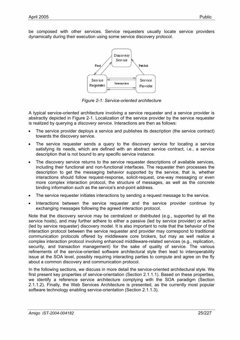
Figure 2-1: Service-oriented architecture
A typical service-oriented architecture involving a service requester and a service provider is abstractly depicted in Figure 2-1. Localization of the service provider by the service requester is realized by querying a discovery service. Interactions are then as follows:
• The service provider deploys a service and publishes its description (the service contract) towards the discovery service.
• The service requester sends a query to the discovery service for locating a service satisfying its needs, which are defined with an abstract service contract, i.e., a service description that is not bound to any specific service instance.
• The discovery service returns to the service requester descriptions of available services, including their functional and non-functional interfaces. The requester then processes the description to get the messaging behavior supported by the service, that is, whether interactions should follow request-response, solicit-request, one-way messaging or even more complex interaction protocol, the structure of messages, as well as the concrete binding information such as the service's end-point address.
• The service requester initiates interactions by sending a request message to the service.
• Interactions between the service requester and the service provider continue by exchanging messages following the agreed interaction protocol.
Note that the discovery service may be centralized or distributed (e.g., supported by all the service hosts), and may further adhere to either a passive (led by service provider) or active (led by service requester) discovery model. It is also important to note that the behavior of the interaction protocol between the service requester and provider may correspond to traditional communication protocols offered by middleware core brokers, but may as well realize a complex interaction protocol involving enhanced middleware-related services (e.g., replication, security, and transaction management) for the sake of quality of service. The various refinements of the service-oriented software architectural style then lead to interoperability issue at the SOA level, possibly requiring interacting parties to compute and agree on the fly about a common discovery and communication protocol.
In the following sections, we discuss in more detail the service-oriented architectural style. We first present key properties of service-orientation (Section 2.1.1.1). Based on these properties, we identify a reference service architecture complying with the SOA paradigm (Section 2.1.1.2). Finally, the Web Services Architecture is presented, as the currently most popular software technology enabling service-orientation (Section 2.1.1.3).
Amigo IST-2004-004182 25/227
April 2005 Public
2.1.1.1 Key properties of service-orientation The benefit of service orientation for software system architectures lies in the looser coupling of the software components making up an application, hence the increased ability to making systems evolve as, e.g., application-level requirements change and the networked environment changes. Specifically, key properties of SOA for the networked home environment include loose coupling, dynamicity and composability, as discussed below.
In a service-oriented architecture, services are provided by autonomously developed and deployed applications. In a dynamic and open system, like the networked home, designing tightly coupled services would compromise the services’ respective autonomy, as they cannot evolve independently. Furthermore, failures would be more frequent in case of unavailability or failure of any of the composed services. Instead, the service-oriented architecture focuses on loosely coupled services. Loosely coupled services depend neither on the implementation of another service (a requester or a third party constituent), nor on the communication infrastructure. To achieve interoperability among diversely designed and deployed systems, services expose a contract describing basically what the service provides, how a service requester should interact with the provider to get the service and the provided quality of service guarantees. Interactions between systems are done by message exchanges. This allows in particular defining asynchronous interactions as well as more complex message exchange patterns by grouping and ordering several one-way messages (e.g., RPC-like messaging by associating a request message with a response message). Moreover, the message structure should be independent of any programming language and communication protocol. A service requester willing to engage in an interaction with a service provider must be able – based solely on this contract – to decide if it can implement the requested interactions. The service contract comprises the functional interface and non-functional attributes describing the service, which is abstractly specified using a common declarative language that can be processed by both parties. The service definition language should be standardized for increased interoperability among software systems that are autonomously developed and deployed. Indeed, the service definition language should not rely on any programming language used for implementing services, and the service being abstractly specified should be as independent as possible from the underlying implementation of the service. The service definition then describes functionalities offered by means of message exchanges, by providing the structure of each message and, optionally, ordering constraints that may be imposed on interactions involving multiple messages exchanges. Non-functional attributes may complement the functional interface by describing the provided support for QoS. Several non-functional properties may be here defined, such as security, availability, dependability, performance etc.
In a distributed open system, the system components and the environment evolve continuously and independently of each other. New services appear, existing services disappear permanently or become temporarily unavailable, services change their interfaces, etc. Moreover, service requesters' functional or non-functional requirements may change over time depending on the context (i.e., both user-centric and computer-centric context). Adaptation to these changes is thus a key feature of the service-oriented architecture, which is supported thanks to service discovery and dynamic binding. To cope with the highly dynamic and unpredictable nature of service availability, services to be integrated in an application are defined using abstract service descriptions. Service requesters locate available services conforming to abstract service descriptions using a service discovery protocol, in general by querying a service registry. On the other hand, service providers make available their offered services by publishing them using the service discovery protocol. The published service descriptions contain the functional and non-functional interfaces of services, and provide as well concrete binding information for accessing the service such as the service's URI and the underlying communication protocol that should be used. Service discovery and integration of available concrete services are done either at runtime, or before the execution of interactions. Each interaction initiated by a service requester in a service-oriented architecture may thus
Amigo IST-2004-004182 26/227
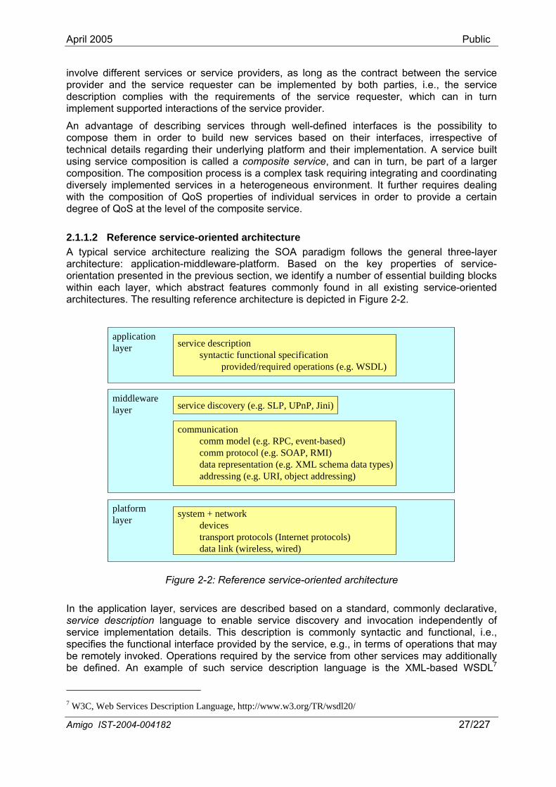
April 2005 Public
involve different services or service providers, as long as the contract between the service provider and the service requester can be implemented by both parties, i.e., the service description complies with the requirements of the service requester, which can in turn implement supported interactions of the service provider.
An advantage of describing services through well-defined interfaces is the possibility to compose them in order to build new services based on their interfaces, irrespective of technical details regarding their underlying platform and their implementation. A service built using service composition is called a composite service, and can in turn, be part of a larger composition. The composition process is a complex task requiring integrating and coordinating diversely implemented services in a heterogeneous environment. It further requires dealing with the composition of QoS properties of individual services in order to provide a certain degree of QoS at the level of the composite service.
2.1.1.2 Reference service-oriented architecture A typical service architecture realizing the SOA paradigm follows the general three-layer architecture: application-middleware-platform. Based on the key properties of service-orientation presented in the previous section, we identify a number of essential building blocks within each layer, which abstract features commonly found in all existing service-oriented architectures. The resulting reference architecture is depicted in Figure 2-2.
middlewarelayer
platformlayer
communicationcomm model (e.g. RPC, event-based)comm protocol (e.g. SOAP, RMI)data representation (e.g. XML schema data types)addressing (e.g. URI, object addressing)
service discovery (e.g. SLP, UPnP, Jini)
applicationlayer service description
syntactic functional specificationprovided/required operations (e.g. WSDL)
system + networkdevicestransport protocols (Internet protocols)data link (wireless, wired)
Figure 2-2: Reference service-oriented architecture
In the application layer, services are described based on a standard, commonly declarative, service description language to enable service discovery and invocation independently of service implementation details. This description is commonly syntactic and functional, i.e., specifies the functional interface provided by the service, e.g., in terms of operations that may be remotely invoked. Operations required by the service from other services may additionally be defined. An example of such service description language is the XML-based WSDL7
7 W3C, Web Services Description Language, http://www.w3.org/TR/wsdl20/
Amigo IST-2004-004182 27/227
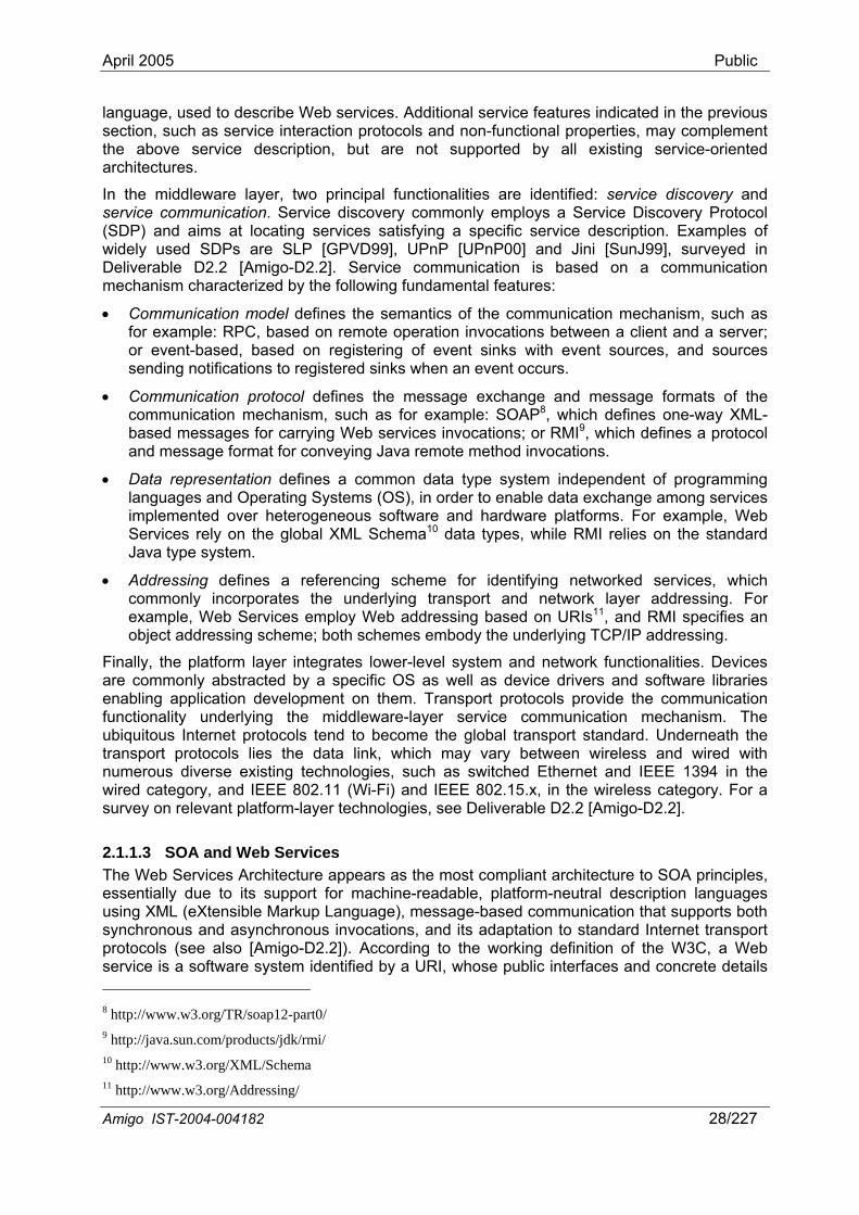
April 2005 Public
language, used to describe Web services. Additional service features indicated in the previous section, such as service interaction protocols and non-functional properties, may complement the above service description, but are not supported by all existing service-oriented architectures.
In the middleware layer, two principal functionalities are identified: service discovery and service communication. Service discovery commonly employs a Service Discovery Protocol (SDP) and aims at locating services satisfying a specific service description. Examples of widely used SDPs are SLP [GPVD99], UPnP [UPnP00] and Jini [SunJ99], surveyed in Deliverable D2.2 [Amigo-D2.2]. Service communication is based on a communication mechanism characterized by the following fundamental features:
• Communication model defines the semantics of the communication mechanism, such as for example: RPC, based on remote operation invocations between a client and a server; or event-based, based on registering of event sinks with event sources, and sources sending notifications to registered sinks when an event occurs.
• Communication protocol defines the message exchange and message formats of the communication mechanism, such as for example: SOAP8, which defines one-way XML-based messages for carrying Web services invocations; or RMI9, which defines a protocol and message format for conveying Java remote method invocations.
• Data representation defines a common data type system independent of programming languages and Operating Systems (OS), in order to enable data exchange among services implemented over heterogeneous software and hardware platforms. For example, Web Services rely on the global XML Schema10 data types, while RMI relies on the standard Java type system.
• Addressing defines a referencing scheme for identifying networked services, which commonly incorporates the underlying transport and network layer addressing. For example, Web Services employ Web addressing based on URIs11, and RMI specifies an object addressing scheme; both schemes embody the underlying TCP/IP addressing.
Finally, the platform layer integrates lower-level system and network functionalities. Devices are commonly abstracted by a specific OS as well as device drivers and software libraries enabling application development on them. Transport protocols provide the communication functionality underlying the middleware-layer service communication mechanism. The ubiquitous Internet protocols tend to become the global transport standard. Underneath the transport protocols lies the data link, which may vary between wireless and wired with numerous diverse existing technologies, such as switched Ethernet and IEEE 1394 in the wired category, and IEEE 802.11 (Wi-Fi) and IEEE 802.15.x, in the wireless category. For a survey on relevant platform-layer technologies, see Deliverable D2.2 [Amigo-D2.2].
2.1.1.3 SOA and Web Services The Web Services Architecture appears as the most compliant architecture to SOA principles, essentially due to its support for machine-readable, platform-neutral description languages using XML (eXtensible Markup Language), message-based communication that supports both synchronous and asynchronous invocations, and its adaptation to standard Internet transport protocols (see also [Amigo-D2.2]). According to the working definition of the W3C, a Web service is a software system identified by a URI, whose public interfaces and concrete details 8 http://www.w3.org/TR/soap12-part0/ 9 http://java.sun.com/products/jdk/rmi/ 10 http://www.w3.org/XML/Schema 11 http://www.w3.org/Addressing/
Amigo IST-2004-004182 28/227
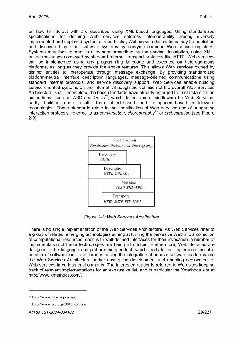
April 2005 Public
on how to interact with are described using XML-based languages. Using standardized specifications for defining Web services enforces interoperability among diversely implemented and deployed systems. In particular, Web service descriptions may be published and discovered by other software systems by querying common Web service registries. Systems may then interact in a manner prescribed by the service description, using XML-based messages conveyed by standard Internet transport protocols like HTTP. Web services can be implemented using any programming language and executed on heterogeneous platforms, as long as they provide the above features. This allows Web services owned by distinct entities to interoperate through message exchange. By providing standardized platform-neutral interface description languages, message-oriented communications using standard Internet protocols, and service discovery support, Web Services enable building service-oriented systems on the Internet. Although the definition of the overall Web Services Architecture is still incomplete, the base standards have already emerged from standardization consortiums such as W3C and Oasis12, which define a core middleware for Web Services, partly building upon results from object-based and component-based middleware technologies. These standards relate to the specification of Web services and of supporting interaction protocols, referred to as conversation, choreography13 or orchestration (see Figure 2-3).
Figure 2-3: Web Services Architecture
There is no single implementation of the Web Services Architecture. As Web Services refer to a group of related, emerging technologies aiming at turning the pervasive Web into a collection of computational resources, each with well-defined interfaces for their invocation, a number of implementation of these technologies are being introduced. Furthermore, Web Services are designed to be language and platform-independent, which leads to the implementation of a number of software tools and libraries easing the integration of popular software platforms into the Web Services Architecture and/or easing the development and enabling deployment of Web services in various environments. The interested reader is referred to Web sites keeping track of relevant implementations for an exhaustive list, and in particular the Xmethods site at http://www.xmethods.com/.
12 http://www.oasis-open.org/ 13 http://www.w3.org/2002/ws/chor
Amigo IST-2004-004182 29/227
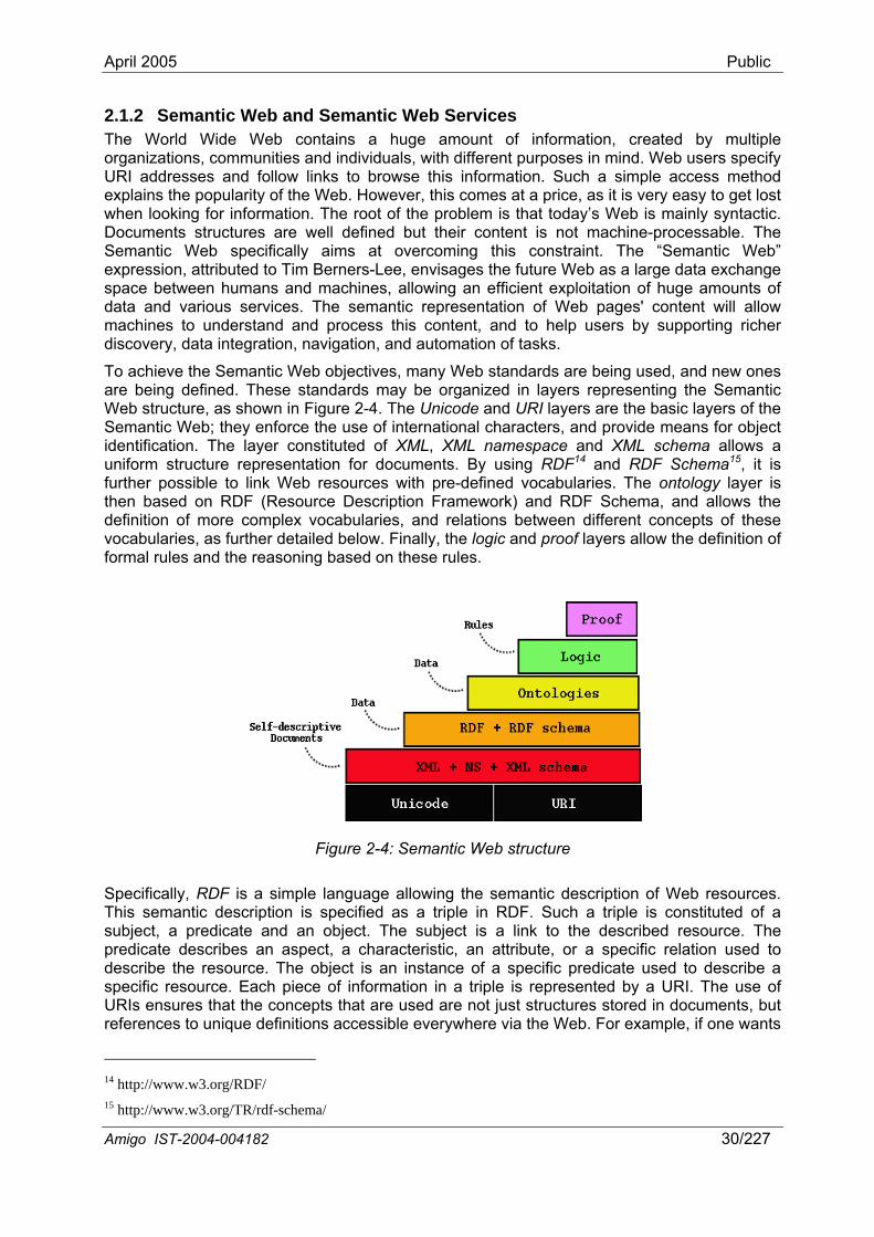
April 2005 Public
2.1.2 Semantic Web and Semantic Web Services The World Wide Web contains a huge amount of information, created by multiple organizations, communities and individuals, with different purposes in mind. Web users specify URI addresses and follow links to browse this information. Such a simple access method explains the popularity of the Web. However, this comes at a price, as it is very easy to get lost when looking for information. The root of the problem is that today’s Web is mainly syntactic. Documents structures are well defined but their content is not machine-processable. The Semantic Web specifically aims at overcoming this constraint. The “Semantic Web” expression, attributed to Tim Berners-Lee, envisages the future Web as a large data exchange space between humans and machines, allowing an efficient exploitation of huge amounts of data and various services. The semantic representation of Web pages' content will allow machines to understand and process this content, and to help users by supporting richer discovery, data integration, navigation, and automation of tasks.
To achieve the Semantic Web objectives, many Web standards are being used, and new ones are being defined. These standards may be organized in layers representing the Semantic Web structure, as shown in Figure 2-4. The Unicode and URI layers are the basic layers of the Semantic Web; they enforce the use of international characters, and provide means for object identification. The layer constituted of XML, XML namespace and XML schema allows a uniform structure representation for documents. By using RDF14 and RDF Schema15, it is further possible to link Web resources with pre-defined vocabularies. The ontology layer is then based on RDF (Resource Description Framework) and RDF Schema, and allows the definition of more complex vocabularies, and relations between different concepts of these vocabularies, as further detailed below. Finally, the logic and proof layers allow the definition of formal rules and the reasoning based on these rules.
Figure 2-4: Semantic Web structure
Specifically, RDF is a simple language allowing the semantic description of Web resources. This semantic description is specified as a triple in RDF. Such a triple is constituted of a subject, a predicate and an object. The subject is a link to the described resource. The predicate describes an aspect, a characteristic, an attribute, or a specific relation used to describe the resource. The object is an instance of a specific predicate used to describe a specific resource. Each piece of information in a triple is represented by a URI. The use of URIs ensures that the concepts that are used are not just structures stored in documents, but references to unique definitions accessible everywhere via the Web. For example, if one wants
14 http://www.w3.org/RDF/ 15 http://www.w3.org/TR/rdf-schema/
Amigo IST-2004-004182 30/227
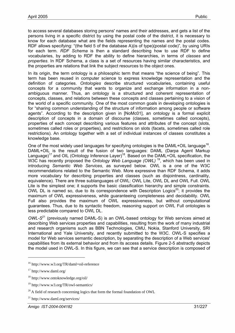
April 2005 Public
to access several databases storing persons' names and their addresses, and gets a list of the persons living in a specific district by using the postal code of the district, it is necessary to know for each database what are the fields representing the names and the postal codes. RDF allows specifying: “(the field 5 of the database A)(is of type)(postal code)”, by using URIs for each term. RDF Schema is then a standard describing how to use RDF to define vocabularies, by adding to RDF the ability to define hierarchies, in terms of classes and properties. In RDF Schema, a class is a set of resources having similar characteristics, and the properties are relations that link the subject resources to the object ones.
In its origin, the term ontology is a philosophic term that means “the science of being”. This term has been reused in computer science to express knowledge representation and the definition of categories. Ontologies describe structured vocabularies, containing useful concepts for a community that wants to organize and exchange information in a non-ambiguous manner. Thus, an ontology is a structured and coherent representation of concepts, classes, and relations between these concepts and classes pertaining to a vision of the world of a specific community. One of the most common goals in developing ontologies is for “sharing common understanding of the structure of information among people or software agents”. According to the description given in [NoMc01], an ontology is a formal explicit description of concepts in a domain of discourse (classes, sometimes called concepts), properties of each concept describing various features and attributes of the concept (slots, sometimes called roles or properties), and restrictions on slots (facets, sometimes called role restrictions). An ontology together with a set of individual instances of classes constitutes a knowledge base.
One of the most widely used languages for specifying ontologies is the DAML+OIL language16. DAML+OIL is the result of the fusion of two languages: DAML (Darpa Agent Markup Language)17 and OIL (Ontology Inference Layer)18. Based on the DAML+OIL specification, the W3C has recently proposed the Ontology Web Language (OWL) 19, which has been used in introducing Semantic Web Services, as surveyed below. OWL is a one of the W3C recommendations related to the Semantic Web. More expressive than RDF Schema, it adds more vocabulary for describing properties and classes (such as disjointness, cardinality, equivalence). There are three sublanguages of OWL: OWL Lite, OWL DL and OWL Full. OWL Lite is the simplest one; it supports the basic classification hierarchy and simple constraints. OWL DL is named so, due to its correspondence with Description Logics20; it provides the maximum of OWL expressiveness, while guaranteeing completeness and decidability. OWL Full also provides the maximum of OWL expressiveness, but without computational guarantees. Thus, due to its syntactic freedom, reasoning support on OWL Full ontologies is less predictable compared to OWL DL.
OWL-S21 (previously named DAML-S) is an OWL-based ontology for Web services aimed at describing Web services properties and capabilities, resulting from the work of many industrial and research organisms such as BBN Technologies, CMU, Nokia, Stanford University, SRI International and Yale University, and recently submitted to the W3C. OWL-S specifies a model for Web services semantic description, by separating the description of a Web services' capabilities from its external behavior and from its access details. Figure 2-5 abstractly depicts the model used in OWL-S. In this figure, we can see that a service description is composed of
16 http://www.w3.org/TR/daml+oil-reference 17 http://www.daml.org/ 18 http://www.ontoknowledge.org/oil/ 19 http://www.w3.org/TR/owl-semantics/ 20 A field of research concerning logics that form the formal foundation of OWL 21 http://www.daml.org/services/
Amigo IST-2004-004182 31/227
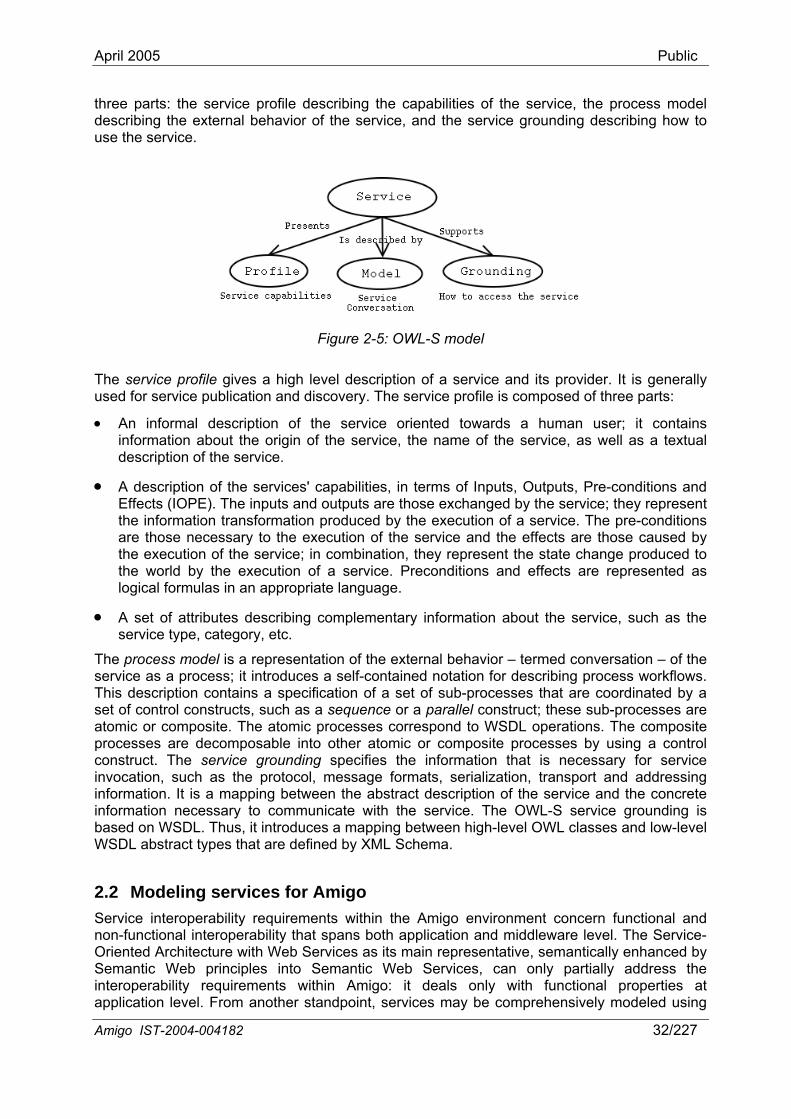
April 2005 Public
three parts: the service profile describing the capabilities of the service, the process model describing the external behavior of the service, and the service grounding describing how to use the service.
Figure 2-5: OWL-S model
The service profile gives a high level description of a service and its provider. It is generally used for service publication and discovery. The service profile is composed of three parts:
• An informal description of the service oriented towards a human user; it contains information about the origin of the service, the name of the service, as well as a textual description of the service.
• A description of the services' capabilities, in terms of Inputs, Outputs, Pre-conditions and Effects (IOPE). The inputs and outputs are those exchanged by the service; they represent the information transformation produced by the execution of a service. The pre-conditions are those necessary to the execution of the service and the effects are those caused by the execution of the service; in combination, they represent the state change produced to the world by the execution of a service. Preconditions and effects are represented as logical formulas in an appropriate language.
• A set of attributes describing complementary information about the service, such as the service type, category, etc.
The process model is a representation of the external behavior – termed conversation – of the service as a process; it introduces a self-contained notation for describing process workflows. This description contains a specification of a set of sub-processes that are coordinated by a set of control constructs, such as a sequence or a parallel construct; these sub-processes are atomic or composite. The atomic processes correspond to WSDL operations. The composite processes are decomposable into other atomic or composite processes by using a control construct. The service grounding specifies the information that is necessary for service invocation, such as the protocol, message formats, serialization, transport and addressing information. It is a mapping between the abstract description of the service and the concrete information necessary to communicate with the service. The OWL-S service grounding is based on WSDL. Thus, it introduces a mapping between high-level OWL classes and low-level WSDL abstract types that are defined by XML Schema.
2.2 Modeling services for Amigo Service interoperability requirements within the Amigo environment concern functional and non-functional interoperability that spans both application and middleware level. The Service-Oriented Architecture with Web Services as its main representative, semantically enhanced by Semantic Web principles into Semantic Web Services, can only partially address the interoperability requirements within Amigo: it deals only with functional properties at application level. From another standpoint, services may be comprehensively modeled using
Amigo IST-2004-004182 32/227
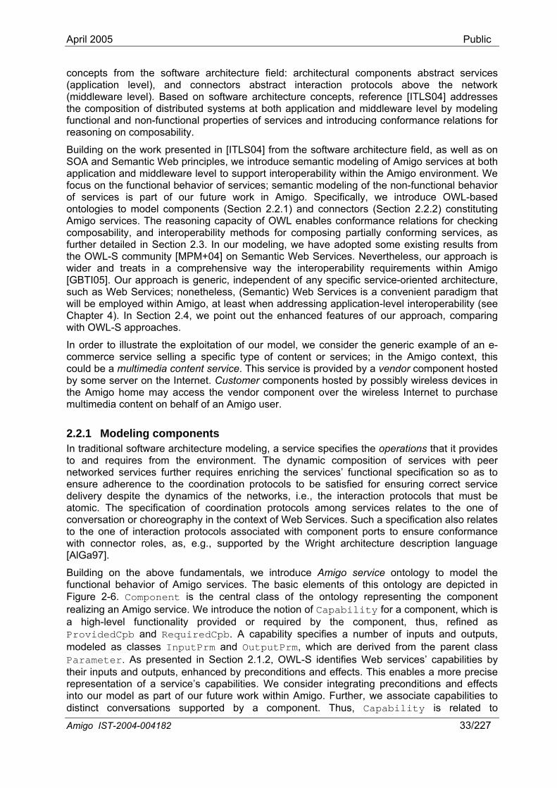
April 2005 Public
concepts from the software architecture field: architectural components abstract services (application level), and connectors abstract interaction protocols above the network (middleware level). Based on software architecture concepts, reference [ITLS04] addresses the composition of distributed systems at both application and middleware level by modeling functional and non-functional properties of services and introducing conformance relations for reasoning on composability.
Building on the work presented in [ITLS04] from the software architecture field, as well as on SOA and Semantic Web principles, we introduce semantic modeling of Amigo services at both application and middleware level to support interoperability within the Amigo environment. We focus on the functional behavior of services; semantic modeling of the non-functional behavior of services is part of our future work in Amigo. Specifically, we introduce OWL-based ontologies to model components (Section 2.2.1) and connectors (Section 2.2.2) constituting Amigo services. The reasoning capacity of OWL enables conformance relations for checking composability, and interoperability methods for composing partially conforming services, as further detailed in Section 2.3. In our modeling, we have adopted some existing results from the OWL-S community [MPM+04] on Semantic Web Services. Nevertheless, our approach is wider and treats in a comprehensive way the interoperability requirements within Amigo [GBTI05]. Our approach is generic, independent of any specific service-oriented architecture, such as Web Services; nonetheless, (Semantic) Web Services is a convenient paradigm that will be employed within Amigo, at least when addressing application-level interoperability (see Chapter 4). In Section 2.4, we point out the enhanced features of our approach, comparing with OWL-S approaches.
In order to illustrate the exploitation of our model, we consider the generic example of an e-commerce service selling a specific type of content or services; in the Amigo context, this could be a multimedia content service. This service is provided by a vendor component hosted by some server on the Internet. Customer components hosted by possibly wireless devices in the Amigo home may access the vendor component over the wireless Internet to purchase multimedia content on behalf of an Amigo user.
2.2.1 Modeling components In traditional software architecture modeling, a service specifies the operations that it provides to and requires from the environment. The dynamic composition of services with peer networked services further requires enriching the services’ functional specification so as to ensure adherence to the coordination protocols to be satisfied for ensuring correct service delivery despite the dynamics of the networks, i.e., the interaction protocols that must be atomic. The specification of coordination protocols among services relates to the one of conversation or choreography in the context of Web Services. Such a specification also relates to the one of interaction protocols associated with component ports to ensure conformance with connector roles, as, e.g., supported by the Wright architecture description language [AlGa97].
Amigo IST-2004-004182 33/227
Building on the above fundamentals, we introduce Amigo service ontology to model the functional behavior of Amigo services. The basic elements of this ontology are depicted in Figure 2-6. Component is the central class of the ontology representing the component realizing an Amigo service. We introduce the notion of Capability for a component, which is a high-level functionality provided or required by the component, thus, refined as ProvidedCpb and RequiredCpb. A capability specifies a number of inputs and outputs, modeled as classes InputPrm and OutputPrm, which are derived from the parent class Parameter. As presented in Section 2.1.2, OWL-S identifies Web services’ capabilities by their inputs and outputs, enhanced by preconditions and effects. This enables a more precise representation of a service’s capabilities. We consider integrating preconditions and effects into our model as part of our future work within Amigo. Further, we associate capabilities to distinct conversations supported by a component. Thus, Capability is related to
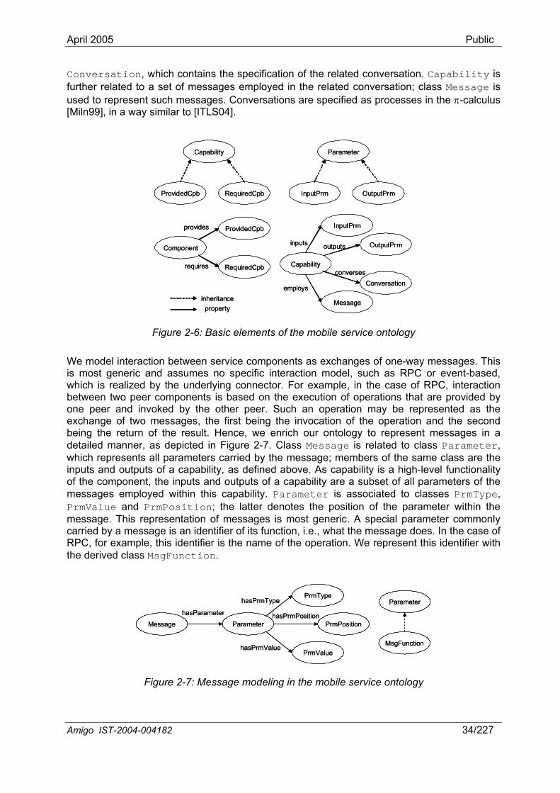
April 2005 Public
Conversation, which contains the specification of the related conversation. Capability is further related to a set of messages employed in the related conversation; class Message is used to represent such messages. Conversations are specified as processes in the π-calculus [Miln99], in a way similar to [ITLS04].
Capability
ProvidedCpb RequiredCpb
Parameter
InputPrm OutputPrm
Component
ProvidedCpb
RequiredCpb
provides
requires Capability
InputPrm
OutputPrminputs outputs
Conversationconverses
Message
employsinheritanceproperty
Capability
ProvidedCpb RequiredCpb
Parameter
InputPrm OutputPrm
Component
ProvidedCpb
RequiredCpb
provides
requires Capability
InputPrm
OutputPrminputs outputs
Conversationconverses
Message
employsinheritanceproperty
Figure 2-6: Basic elements of the mobile service ontology
We model interaction between service components as exchanges of one-way messages. This is most generic and assumes no specific interaction model, such as RPC or event-based, which is realized by the underlying connector. For example, in the case of RPC, interaction between two peer components is based on the execution of operations that are provided by one peer and invoked by the other peer. Such an operation may be represented as the exchange of two messages, the first being the invocation of the operation and the second being the return of the result. Hence, we enrich our ontology to represent messages in a detailed manner, as depicted in Figure 2-7. Class Message is related to class Parameter, which represents all parameters carried by the message; members of the same class are the inputs and outputs of a capability, as defined above. As capability is a high-level functionality of the component, the inputs and outputs of a capability are a subset of all parameters of the messages employed within this capability. Parameter is associated to classes PrmType, PrmValue and PrmPosition; the latter denotes the position of the parameter within the message. This representation of messages is most generic. A special parameter commonly carried by a message is an identifier of its function, i.e., what the message does. In the case of RPC, for example, this identifier is the name of the operation. We represent this identifier with the derived class MsgFunction.
Message
hasParameter
Parameter
PrmType
PrmValue
hasPrmType
hasPrmPositionPrmPosition
hasPrmValue
Parameter
MsgFunction
Message
hasParameter
Parameter
PrmType
PrmValue
hasPrmType
hasPrmPositionPrmPosition
hasPrmValue
Parameter
MsgFunction
Figure 2-7: Message modeling in the mobile service ontology
Amigo IST-2004-004182 34/227
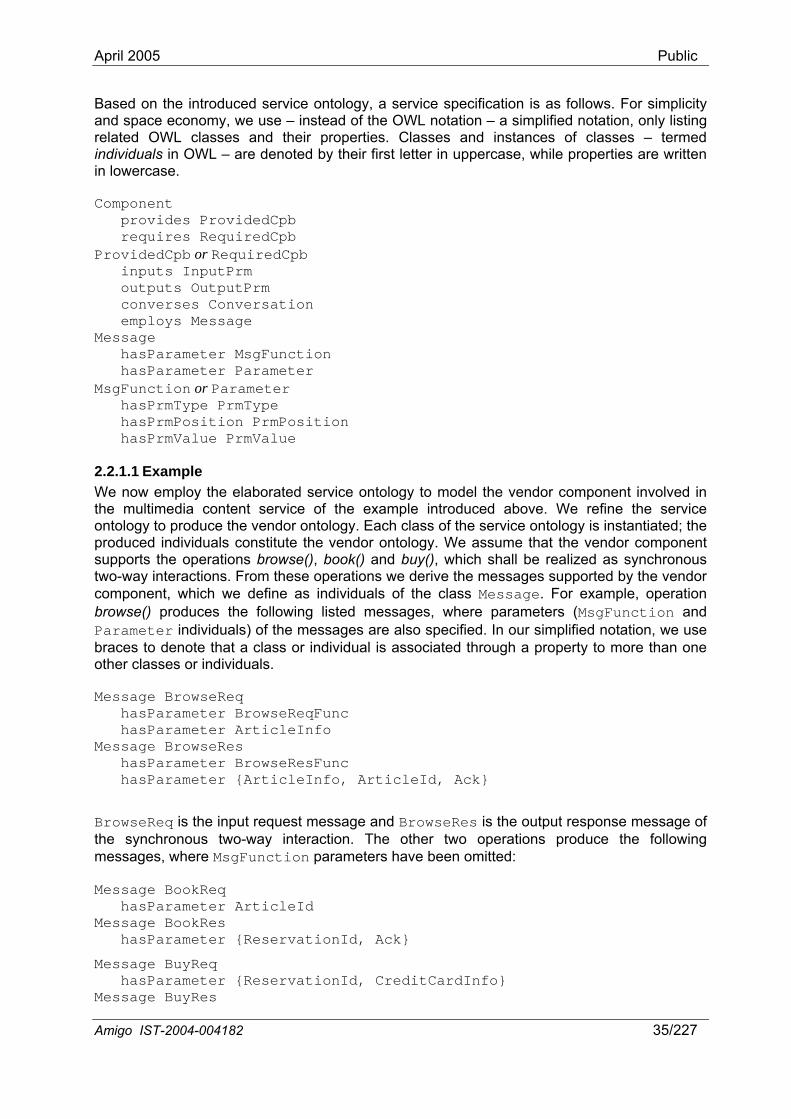
April 2005 Public
Based on the introduced service ontology, a service specification is as follows. For simplicity and space economy, we use – instead of the OWL notation – a simplified notation, only listing related OWL classes and their properties. Classes and instances of classes – termed individuals in OWL – are denoted by their first letter in uppercase, while properties are written in lowercase.
Component provides ProvidedCpb requires RequiredCpb ProvidedCpb or RequiredCpb inputs InputPrm outputs OutputPrm converses Conversation employs Message Message hasParameter MsgFunction hasParameter Parameter MsgFunction or Parameter hasPrmType PrmType hasPrmPosition PrmPosition hasPrmValue PrmValue
2.2.1.1 Example We now employ the elaborated service ontology to model the vendor component involved in the multimedia content service of the example introduced above. We refine the service ontology to produce the vendor ontology. Each class of the service ontology is instantiated; the produced individuals constitute the vendor ontology. We assume that the vendor component supports the operations browse(), book() and buy(), which shall be realized as synchronous two-way interactions. From these operations we derive the messages supported by the vendor component, which we define as individuals of the class Message. For example, operation browse() produces the following listed messages, where parameters (MsgFunction and Parameter individuals) of the messages are also specified. In our simplified notation, we use braces to denote that a class or individual is associated through a property to more than one other classes or individuals.
Message BrowseReq hasParameter BrowseReqFunc hasParameter ArticleInfo Message BrowseRes hasParameter BrowseResFunc hasParameter {ArticleInfo, ArticleId, Ack}
BrowseReq is the input request message and BrowseRes is the output response message of the synchronous two-way interaction. The other two operations produce the following messages, where MsgFunction parameters have been omitted:
Message BookReq hasParameter ArticleId Message BookRes hasParameter {ReservationId, Ack}
Message BuyReq hasParameter {ReservationId, CreditCardInfo} Message BuyRes
Amigo IST-2004-004182 35/227
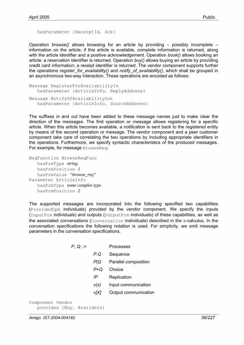
April 2005 Public
hasParameter {ReceiptId, Ack}
Operation browse() allows browsing for an article by providing – possibly incomplete – information on the article; if this article is available, complete information is returned, along with the article identifier and a positive acknowledgement. Operation book() allows booking an article; a reservation identifier is returned. Operation buy() allows buying an article by providing credit card information; a receipt identifier is returned. The vendor component supports further the operations register_for_availability() and notify_of_availability(), which shall be grouped in an asynchronous two-way interaction. These operations are encoded as follows:
Message RegisterForAvailabilityIn hasParameter {ArticleInfo, ReplyAddress}
Message NotifyOfAvailabilityOut hasParameter {ArticleInfo, SourceAddress}
The suffixes in and out have been added to these message names just to make clear the direction of the messages. The first operation or message allows registering for a specific article. When this article becomes available, a notification is sent back to the registered entity by means of the second operation or message. The vendor component and a peer customer component take care of correlating the two operations by including appropriate identifiers in the operations. Furthermore, we specify syntactic characteristics of the produced messages. For example, for message BrowseReq:
MsgFunction BrowseReqFunc hasPrmType string hasPrmPosition 1 hasPrmValue “browse_req” Parameter ArticleInfo hasPrmType some complex type hasPrmPosition 2
The supported messages are incorporated into the following specified two capabilities (ProvidedCpb individuals) provided by the vendor component. We specify the inputs (InputPrm individuals) and outputs (OutputPrm individuals) of these capabilities, as well as the associated conversations (Conversation individuals) described in the π-calculus. In the conversation specifications the following notation is used. For simplicity, we omit message parameters in the conversation specifications.
P, Q ::= Processes
P.Q Sequence
P|Q Parallel composition
P+Q Choice
!P Replication
v(x) Input communication
v[X] Output communication
Component Vendor provides {Buy, Available}
Amigo IST-2004-004182 36/227
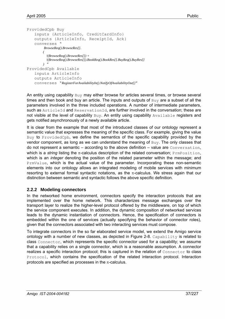
April 2005 Public
ProvidedCpb Buy inputs {ArticleInfo, CreditCardInfo} outputs {ArticleInfo, ReceiptId, Ack} converses “ BrowseReq().BrowseRes[]. ( !(BrowseReq().BrowseRes[]) + !(BrowseReq().BrowseRes[]).BookReq().BookRes[].BuyReq().BuyRes[] ) ” ProvidedCpb Available inputs ArticleInfo outputs ArticleInfo converses “RegisterForAvailabilityIn().NotifyOfAvailabilityOut[]”
An entity using capability Buy may either browse for articles several times, or browse several times and then book and buy an article. The inputs and outputs of Buy are a subset of all the parameters involved in the three included operations. A number of intermediate parameters, such as ArticleId and ReservationId, are further involved in the conversation; these are not visible at the level of capability Buy. An entity using capability Available registers and gets notified asynchronously of a newly available article.
It is clear from the example that most of the introduced classes of our ontology represent a semantic value that expresses the meaning of the specific class. For example, giving the value Buy to ProvidedCpb, we define the semantics of the specific capability provided by the vendor component, as long as we can understand the meaning of Buy. The only classes that do not represent a semantic – according to the above definition – value are Conversation, which is a string listing the π-calculus description of the related conversation; PrmPosition, which is an integer denoting the position of the related parameter within the message; and PrmValue, which is the actual value of the parameter. Incorporating these non-semantic elements into our ontology allows an integrated modeling of mobile services with minimum resorting to external formal syntactic notations, as the π-calculus. We stress again that our distinction between semantic and syntactic follows the above specific definition.
2.2.2 Modeling connectors In the networked home environment, connectors specify the interaction protocols that are implemented over the home network. This characterizes message exchanges over the transport layer to realize the higher-level protocol offered by the middleware, on top of which the service component executes. In addition, the dynamic composition of networked services leads to the dynamic instantiation of connectors. Hence, the specification of connectors is embedded within the one of services (actually specifying the behavior of connector roles), given that the connectors associated with two interacting services must compose.
To integrate connectors in the so far elaborated service model, we extend the Amigo service ontology with a number of new classes, as depicted in Figure 2-8. Capability is related to class Connector, which represents the specific connector used for a capability; we assume that a capability relies on a single connector, which is a reasonable assumption. A connector realizes a specific interaction protocol; this is captured in the relation of Connector to class Protocol, which contains the specification of the related interaction protocol. Interaction protocols are specified as processes in the π-calculus.
Amigo IST-2004-004182 37/227

April 2005 Public
Capability Connector
supportedBy
Connector
Protocolinteracts
Messageexchanges
Addressreferences
Parameter
Address
LocalAddr RemoteAddr
Capability Connector
supportedBy
Connector
Protocolinteracts
Messageexchanges
Addressreferences
Parameter
Address
LocalAddr RemoteAddr
Figure 2-8: Connector modeling in the mobile service ontology
An interaction protocol realizes a specific interaction model for the overlying component, such as RPC or event-based. This interaction model is implicitly specified in the π-calculus description of the interaction protocol. Nevertheless, the interaction model may additionally be semantically represented by class Connector. As there is a large variety of connectors and associated interaction models [MeMP99], there is no meaning in enriching the generic service ontology with a taxonomy of connectors. Class Connector may be associated to external ontologies on a case by case basis to represent the interaction model supported by a specific connector.
Furthermore, a connector supports an addressing scheme for identifying itself as well as its associated component over a network realized by the underlying transport layer. A number of different approaches are allowed here, depending on the addressing functionality already supported by the transport layer and on the multiplexing capability of the connector, i.e., its capability to support multiple components. The latter further relates to a connector acting as a container for components, e.g., a Web server being a container for Web applications. Thus, considering the Web Services example, we may distinguish the following addressing levels:
• The TCP/IP transport layer supports IP or name addressing of host machines.
• A Web Services SOAP/HTTP connector binds to a specific TCP port; in this case, the transport layer specifies an addressing scheme for the overlying connectors.
• The SOAP/HTTP connector supports addressing of multiple Web service components, treating Web services as Web resources; thus, incorporating the underlying IP address & port number addressing scheme, the SOAP/HTTP connector supports URI addressing.
To be most generic, we enable a connector addressing scheme without assuming any connector addressing pre-specified by the transport layer. This scheme shall incorporate the established transport layer addressing. Moreover, this scheme shall integrate component identifiers for distinguishing among multiple components supported by a single connector, when this is the case. The introduced generic scheme is represented by the relation of Connector to class Address. Thus, Address represents a reference of a mobile service component accessible through a specific connector and underlying transport layer. Address is a subclass of Parameter.
Class Connector is further related to a set of messages exchanged in the related interaction protocol, which are members of the class Message. This is the same generic class used for component-level messages, as it also applies very well to connector-level messages. Communication between connectors can naturally be modeled as exchange of one-way messages; this takes place on top of the underlying transport layer. To enable component addressing, connector-level messages integrate addressing information. We enable connector-level messages to carry complete addressing information, assuming no addressing information added by the transport layer; certainly, this scheme may easily be adapted according to the addressing capabilities of the transport layer. We introduce two subclasses of Amigo IST-2004-004182 38/227
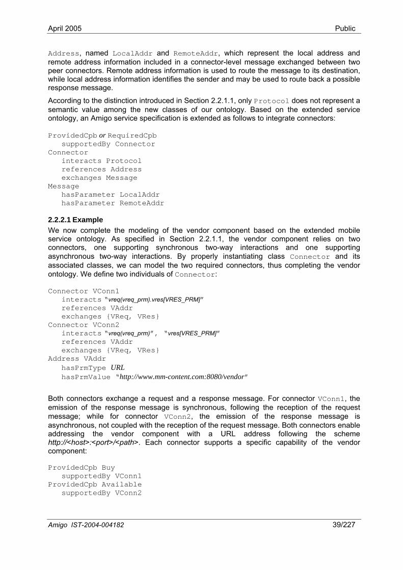
April 2005 Public
Address, named LocalAddr and RemoteAddr, which represent the local address and remote address information included in a connector-level message exchanged between two peer connectors. Remote address information is used to route the message to its destination, while local address information identifies the sender and may be used to route back a possible response message.
According to the distinction introduced in Section 2.2.1.1, only Protocol does not represent a semantic value among the new classes of our ontology. Based on the extended service ontology, an Amigo service specification is extended as follows to integrate connectors:
ProvidedCpb or RequiredCpb supportedBy Connector Connector interacts Protocol references Address exchanges Message Message hasParameter LocalAddr hasParameter RemoteAddr
2.2.2.1 Example We now complete the modeling of the vendor component based on the extended mobile service ontology. As specified in Section 2.2.1.1, the vendor component relies on two connectors, one supporting synchronous two-way interactions and one supporting asynchronous two-way interactions. By properly instantiating class Connector and its associated classes, we can model the two required connectors, thus completing the vendor ontology. We define two individuals of Connector:
Connector VConn1 interacts “vreq(vreq_prm).vres[VRES_PRM]” references VAddr exchanges {VReq, VRes} Connector VConn2 interacts “vreq(vreq_prm)”, “vres[VRES_PRM]” references VAddr exchanges {VReq, VRes} Address VAddr hasPrmType URL hasPrmValue “http://www.mm-content.com:8080/vendor”
Both connectors exchange a request and a response message. For connector VConn1, the emission of the response message is synchronous, following the reception of the request message; while for connector VConn2, the emission of the response message is asynchronous, not coupled with the reception of the request message. Both connectors enable addressing the vendor component with a URL address following the scheme http://<host>:<port>/<path>. Each connector supports a specific capability of the vendor component:
ProvidedCpb Buy supportedBy VConn1 ProvidedCpb Available supportedBy VConn2
Amigo IST-2004-004182 39/227
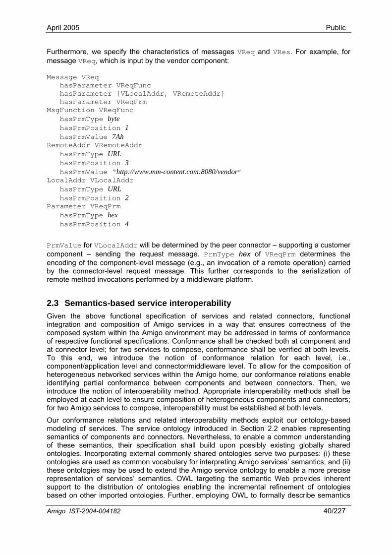
April 2005 Public
Furthermore, we specify the characteristics of messages VReq and VRes. For example, for message VReq, which is input by the vendor component:
Message VReq hasParameter VReqFunc hasParameter {VLocalAddr, VRemoteAddr} hasParameter VReqPrm MsgFunction VReqFunc hasPrmType byte hasPrmPosition 1 hasPrmValue 7Ah RemoteAddr VRemoteAddr hasPrmType URL hasPrmPosition 3 hasPrmValue “http://www.mm-content.com:8080/vendor” LocalAddr VLocalAddr hasPrmType URL hasPrmPosition 2 Parameter VReqPrm hasPrmType hex hasPrmPosition 4
PrmValue for VLocalAddr will be determined by the peer connector – supporting a customer component – sending the request message. PrmType hex of VReqPrm determines the encoding of the component-level message (e.g., an invocation of a remote operation) carried by the connector-level request message. This further corresponds to the serialization of remote method invocations performed by a middleware platform.
2.3 Semantics-based service interoperability Given the above functional specification of services and related connectors, functional integration and composition of Amigo services in a way that ensures correctness of the composed system within the Amigo environment may be addressed in terms of conformance of respective functional specifications. Conformance shall be checked both at component and at connector level; for two services to compose, conformance shall be verified at both levels. To this end, we introduce the notion of conformance relation for each level, i.e., component/application level and connector/middleware level. To allow for the composition of heterogeneous networked services within the Amigo home, our conformance relations enable identifying partial conformance between components and between connectors. Then, we introduce the notion of interoperability method. Appropriate interoperability methods shall be employed at each level to ensure composition of heterogeneous components and connectors; for two Amigo services to compose, interoperability must be established at both levels.
Our conformance relations and related interoperability methods exploit our ontology-based modeling of services. The service ontology introduced in Section 2.2 enables representing semantics of components and connectors. Nevertheless, to enable a common understanding of these semantics, their specification shall build upon possibly existing globally shared ontologies. Incorporating external commonly shared ontologies serve two purposes: (i) these ontologies are used as common vocabulary for interpreting Amigo services’ semantics; and (ii) these ontologies may be used to extend the Amigo service ontology to enable a more precise representation of services’ semantics. OWL targeting the semantic Web provides inherent support to the distribution of ontologies enabling the incremental refinement of ontologies based on other imported ontologies. Further, employing OWL to formally describe semantics
Amigo IST-2004-004182 40/227
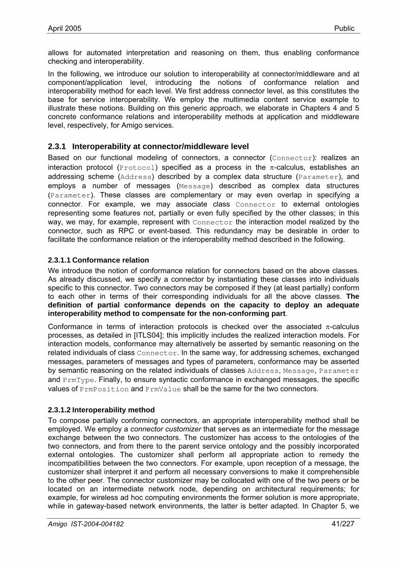
April 2005 Public
allows for automated interpretation and reasoning on them, thus enabling conformance checking and interoperability.
In the following, we introduce our solution to interoperability at connector/middleware and at component/application level, introducing the notions of conformance relation and interoperability method for each level. We first address connector level, as this constitutes the base for service interoperability. We employ the multimedia content service example to illustrate these notions. Building on this generic approach, we elaborate in Chapters 4 and 5 concrete conformance relations and interoperability methods at application and middleware level, respectively, for Amigo services.
2.3.1 Interoperability at connector/middleware level Based on our functional modeling of connectors, a connector (Connector): realizes an interaction protocol (Protocol) specified as a process in the π-calculus, establishes an addressing scheme (Address) described by a complex data structure (Parameter), and employs a number of messages (Message) described as complex data structures (Parameter). These classes are complementary or may even overlap in specifying a connector. For example, we may associate class Connector to external ontologies representing some features not, partially or even fully specified by the other classes; in this way, we may, for example, represent with Connector the interaction model realized by the connector, such as RPC or event-based. This redundancy may be desirable in order to facilitate the conformance relation or the interoperability method described in the following.
2.3.1.1 Conformance relation We introduce the notion of conformance relation for connectors based on the above classes. As already discussed, we specify a connector by instantiating these classes into individuals specific to this connector. Two connectors may be composed if they (at least partially) conform to each other in terms of their corresponding individuals for all the above classes. The definition of partial conformance depends on the capacity to deploy an adequate interoperability method to compensate for the non-conforming part.
Conformance in terms of interaction protocols is checked over the associated π-calculus processes, as detailed in [ITLS04]; this implicitly includes the realized interaction models. For interaction models, conformance may alternatively be asserted by semantic reasoning on the related individuals of class Connector. In the same way, for addressing schemes, exchanged messages, parameters of messages and types of parameters, conformance may be asserted by semantic reasoning on the related individuals of classes Address, Message, Parameter and PrmType. Finally, to ensure syntactic conformance in exchanged messages, the specific values of PrmPosition and PrmValue shall be the same for the two connectors.
2.3.1.2 Interoperability method To compose partially conforming connectors, an appropriate interoperability method shall be employed. We employ a connector customizer that serves as an intermediate for the message exchange between the two connectors. The customizer has access to the ontologies of the two connectors, and from there to the parent service ontology and the possibly incorporated external ontologies. The customizer shall perform all appropriate action to remedy the incompatibilities between the two connectors. For example, upon reception of a message, the customizer shall interpret it and perform all necessary conversions to make it comprehensible to the other peer. The connector customizer may be collocated with one of the two peers or be located on an intermediate network node, depending on architectural requirements; for example, for wireless ad hoc computing environments the former solution is more appropriate, while in gateway-based network environments, the latter is better adapted. In Chapter 5, we
Amigo IST-2004-004182 41/227
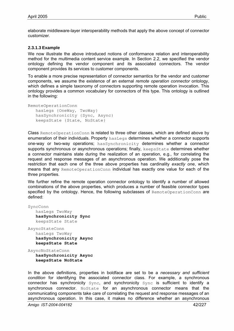
April 2005 Public
elaborate middleware-layer interoperability methods that apply the above concept of connector customizer.
2.3.1.3 Example We now illustrate the above introduced notions of conformance relation and interoperability method for the multimedia content service example. In Section 2.2, we specified the vendor ontology defining the vendor component and its associated connectors. The vendor component provides its services to customer components.
To enable a more precise representation of connector semantics for the vendor and customer components, we assume the existence of an external remote operation connector ontology, which defines a simple taxonomy of connectors supporting remote operation invocation. This ontology provides a common vocabulary for connectors of this type. This ontology is outlined in the following:
RemoteOperationConn hasLegs {OneWay, TwoWay} hasSynchronicity {Sync, Async} keepsState {State, NoState}
Class RemoteOperationConn is related to three other classes, which are defined above by enumeration of their individuals. Property hasLegs determines whether a connector supports one-way or two-way operations; hasSynchronicity determines whether a connector supports synchronous or asynchronous operations; finally, keepsState determines whether a connector maintains state during the realization of an operation, e.g., for correlating the request and response messages of an asynchronous operation. We additionally pose the restriction that each one of the three above properties has cardinality exactly one, which means that any RemoteOperationConn individual has exactly one value for each of the three properties.
We further refine the remote operation connector ontology to identify a number of allowed combinations of the above properties, which produces a number of feasible connector types specified by the ontology. Hence, the following subclasses of RemoteOperationConn are defined:
SyncConn hasLegs TwoWay hasSynchronicity Sync keepsState State
AsyncStateConn hasLegs TwoWay hasSynchronicity Async keepsState State
AsyncNoStateConn hasSynchronicity Async keepsState NoState
In the above definitions, properties in boldface are set to be a necessary and sufficient condition for identifying the associated connector class. For example, a synchronous connector has synchronicity Sync, and synchronicity Sync is sufficient to identify a synchronous connector. NoState for an asynchronous connector means that the communicating components take care of correlating the request and response messages of an asynchronous operation. In this case, it makes no difference whether an asynchronous Amigo IST-2004-004182 42/227
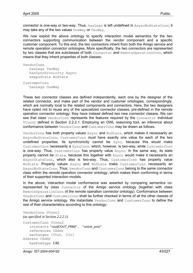
April 2005 Public
connector is one-way or two-way. Thus, hasLegs is left undefined in AsyncNoStateConn; it may take any of the two values OneWay or TwoWay.
We now exploit the above ontology to specify interaction model semantics for the two connectors supporting communication between the vendor component and a specific customer component. To this end, the two connectors inherit from both the Amigo service and remote operation connector ontologies. More specifically, the two connectors are represented by two classes that are subclasses of both Connector and RemoteOperationConn, which means that they inherit properties of both classes:
VendorConn hasLegs TwoWay hasSynchronicity Async keepsState NoState
CustomerConn hasLegs OneWay
These two connector classes are defined independently, each one by the designer of the related connector, and make part of the vendor and customer ontologies, correspondingly, which are normally local to the related components and connectors. Here, the two designers have opted not to reuse any of the specialized connector classes, pre-defined in the remote operation connector ontology; they have instead defined two new connector classes. We can see that class VendorConn represents the features required by the Connector individual VConn2 defined in Section 2.2.2.1. Employing an OWL reasoning tool, an inference about conformance between VendorConn and CustomerConn may be drawn as follows.
VendorConn has both property values Async and NoState, which makes it necessarily an AsyncNoStateConn. CustomerConn must have exactly one value for each of the two undefined properties. Its synchronicity cannot be Sync, because this would make CustomerConn necessarily a SyncConn, which, however, is two-way, while CustomerConn is one-way. Thus, CustomerConn has property value Async. In the same way, its state property cannot be State, because this together with Async would make it necessarily an AsyncStateConn, which also is two-way. Thus, CustomerConn has property value NoState. Property values Async and NoState make CustomerConn necessarily an AsyncNoStateConn. Thus, VendorConn and CustomerConn belong to the same connector class within the remote operation connector ontology, which makes them conforming in terms of their supported interaction models.
In the above, interaction model conformance was asserted by comparing semantics co-represented by class Connector of the Amigo service ontology (together with class RemoteOperationConn of the remote operation connector ontology). Conformance between VendorConn and CustomerConn shall be further checked in terms of all the other classes of the Amigo service ontology. We instantiate VendorConn and CustomerConn to define the rest of their characteristics according to this ontology:
VendorConn VConn2 (as specified in Section 2.2.2.1) CustomerConn CConn2 interacts “cout[COUT_PRM]”, “cin(cin_prm)” references CAddr exchanges {COut, CIn} Address CAddr hasPrmType URL
Amigo IST-2004-004182 43/227
April 2005 Public
hasPrmValue some URL Message COut hasParameter COutFunc hasParameter {CLocalAddr, CRemoteAddr} hasParameter COutPrm MsgFunction COutFunc hasPrmType word hasPrmPosition 1 hasPrmValue 3FEDh RemoteAddr CRemoteAddr hasPrmType URL hasPrmPosition 2 hasPrmValue “http://www.mm-content.com:8080/vendor” LocalAddr CLocalAddr hasPrmType URL hasPrmPosition 3 Parameter COutPrm hasPrmType bin hasPrmPosition 4
Interaction protocol conformance for VConn2 and CConn2 is checked over the associated π-calculus processes, which are obviously complementary (see [ITLS04]); however, different names are used for messages VReq-COut, VRes-CIn and for message parameters VReqPrm-COutPrm, VResPrm-CInPrm. Semantic conformance between corresponding messages and parameters is asserted by using external ontologies, as already done for semantic conformance between interaction models. In the same way, semantic conformance is asserted between addressing schemes (VAddr-CAddr).
Thus, the conformance relation applied to the current example requires: (i) semantic conformance between interaction models, addressing schemes, messages and message parameters; and (ii) workflow conformance between interaction protocols.
Nevertheless, there are still incompatibilities between VConn2 and CConn2 in terms of types of parameters (e.g., between VReqPrm and COutPrm), position of parameters within messages (e.g., between VRemoteAddr and CRemoteAddr within VReq and COut), and values of parameters (e.g., between VReqFunc and COutFunc). Further, referenced types such as URL, byte, word, hex and bin may not belong to the same type system. Thus, we need a connector customizer which resolves these incompatibilities by (i) converting between types by accessing some external type ontology; if different type systems are used, external ontologies can help in converting between type systems; (ii) modifying position of parameters; and (iii) modifying values of parameters. This customizer exploits the semantic conformance established above to identify the semantically corresponding messages and message parameters of VConn2 and CConn2.
A weaker conformance relation than the one applied to this example would require a more competent interoperability method, e.g., a connector customizer capable of resolving incompatibilities in addressing schemes or even in interaction models and workflows of interaction protocols. The feasibility of such cases depends on the nature of addressing schemes or interaction protocols and the degree of heterogeneity, and shall be treated on a case-by-case basis. Enabling automated, dynamic configuration or even generation of the appropriate interoperability method from some persistent registry of generic interoperability methods is then a challenging objective. Ontologies could then be used to represent generic interoperability methods and to guide the automated generation or configuration of these methods based on the concrete ontologies of the two incompatible connectors. In Chapter 5,
Amigo IST-2004-004182 44/227
April 2005 Public
we elaborate a concrete approach to the automated adaptation of interoperability methods according to the dynamic situation.
2.3.2 Interoperability at component/application level Based on our functional modeling of Amigo service components, a component provides or requires a number of capabilities (ProvidedCpb, RequiredCpb). Each capability: has a number of inputs (InputPrm) and outputs (OutputPrm) described as complex data structures (Parameter), realizes a conversation (Conversation) specified as a process in the π-calculus, and employs a number of messages (Message) described as complex data structures (Parameter). Based on the similarity of capability Conversation to connector Protocol and on the common use of Message by both capabilities and connectors, we can introduce a conformance relation and associated interoperability method for component capabilities similar to the ones elaborated for connectors. Workflow conformance between component conversations is required in certain cases where both components need to manage their own internal state transitions during the conversation. Nevertheless, if this is not the case and considering the diversity of component capabilities and conversations, requiring workflow conformance between component conversations and semantic conformance for each single message and message parameter – as for the two connectors in the example above – is too restrictive. Moreover, the introduced connector-level interoperability method, based on communication interworking, cannot deal with the high heterogeneity of components, e.g., it cannot resolve highly incompatible component conversations. Therefore, we introduce, alternatively, a more flexible, coarse-grained approach for component conformance and interoperability based on component capabilities. In the following sections, we present the latter approach, while in Chapter 4, where we address composition of multiple services, we elaborate a conformance relation and associated interoperability method focusing on matching component conversations.
2.3.2.1 Conformance relation Our high-level conformance relation for components states that two components may be composed if they require and provide in a complementary way semantically conforming capabilities. We model a capability by instantiating classes ProvidedCpb or RequiredCpb, InputPrm and OutputPrm into individuals specific to this capability. Semantic conformance between two capabilities is asserted by reasoning on their corresponding individuals. As already detailed for connectors, these individuals shall as well inherit from external ontologies; this allows a rich representation of capabilities based on common vocabularies, which enable their interpretation and conformance checking.
Depending on the existence of external ontologies, capabilities may be directly provided with their semantics (class ProvidedCpb or RequiredCpb). Alternatively, capabilities may be semantically characterized by the semantics of their inputs and outputs (classes InputPrm and OutputPrm). As discussed in [SPAS03] for Semantic Web Services capabilities, the latter approach requires a reduced set of ontologies, as inputs and outputs may be combined in many diverse ways to produce an indefinite number of capabilities. However, semantically characterizing a capability based only on its inputs and outputs may produce ambiguity and erroneous assertions, e.g., when checking conformance between capabilities. We opt for a hybrid approach, where, depending on the availability of related ontologies, both capability semantics and input/output semantics are used. Further, as we have already stated, we consider integrating preconditions and effects into our model to represent service capabilities in a more precise way.
Our conformance relation adopts the approach presented in [PKPS02] for matching Semantic Web services’ capabilities, which identifies several degrees of matching: (i) exact; (ii) plug in, where the provided capability is more general than the requested one, thus it can be used; (iii)
Amigo IST-2004-004182 45/227
April 2005 Public
subsume, where the provided capability is more specific than the requested one, thus it may be used in combination with another Web service complementing the missing part; and (iv) fail. As we are assessing conformance between two peer components, we exclude case (iii). For composition of multiple services, we would consider this case, too; this relates to Chapter 4, although a different conformance relation is employed there. Our conformance relation requires that inputs of a required capability be a superset of inputs of the associated provided capability, while outputs of a required capability be a subset of outputs of the associated provided capability. This refers to both the number of equivalent inputs and outputs and to subsumption relations between mapped inputs and outputs. Equivalence and subsumption are asserted by semantic reasoning, where the degree of similarity may be measured as the distance between concepts in an ontology hierarchy. This approach ensures that a service is fed at least with all the needed input and produces at least all the required output.
2.3.2.2 Interoperability method To compose the high-level-conforming components resulting from the introduced conformance relation, an appropriate interoperability method shall be employed. To this end, we intervene in the execution properties of the component requiring the specific capability. First, the component providing the specific capability is a normal component, the executable of which integrates the hard-coded implementation of the conversation and messages associated to the capability. Thus, this component exposes a normal specific functional interface. Regarding the component requiring the specific capability, its executable is built around this capability, which may be represented as a high-level local function call. This component integrates further an execution engine able to execute on the fly the specific conversation associated to this capability and supported by its peer component. Thus, this component comprises a specific part implementing the component logic that uses this capability, and a generic part constituting a generic interface capable of being composed with diverse peer interfaces. The introduced interoperability method along with the associated conformance relation introduced in the previous section are depicted in Figure 2-9. The execution engine shall be capable of:
• Executing the declarative descriptions of conversations; to this end, execution semantics of the π-calculus descriptions are employed;
• Parsing the incoming messages and synthesizing the outgoing messages of the conversation based on the syntactic information provided by classes PrmType, PrmPosition and PrmValue; access to an external type ontology may be necessary if the type system of the peer is different to the native type system;
• Associating the inputs and outputs of the required capability to their corresponding message parameters; this is based on semantic mapping with the inputs and outputs of the remote capability, which are directly associated to message parameters; conversion between different types or between different type systems may be required.
It is clear from the above that for components it is not necessary to provide messages and message parameters – at least parameters that are not capability inputs or outputs – with semantics.
The introduced component-level interoperability method shall be employed in combination with the connector-level interoperability method discussed in previous sections to ensure service interoperability. It is apparent from the above that the component-level method is more adaptive and can resolve higher heterogeneity than the connector-level one, which is appropriate for components, considering their diversity. On the other hand, the connector-level method permits lower heterogeneity, which is normal for connectors, which shall not be allowed to deviate significantly from the behavior expected by the overlying component. By locating the connector customizer on the side of the component requiring a specific capability, this component becomes capable of adapting itself at both component and connector level to the component providing the specific capability. Employing dynamic schemes for the
Amigo IST-2004-004182 46/227
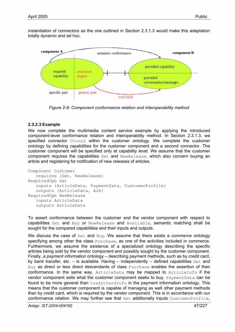
April 2005 Public
instantiation of connectors as the one outlined in Section 2.3.1.3 would make this adaptation totally dynamic and ad hoc.
required capability
execution engine
generic partspecific part
provided capability
component A component B
provided conversation/messages
semantic conformance
execution
Figure 2-9: Component conformance relation and interoperability method
2.3.2.3 Example We now complete the multimedia content service example by applying the introduced component-level conformance relation and interoperability method. In Section 2.3.1.3, we specified connector CConn2 within the customer ontology. We complete the customer ontology by defining capabilities for the customer component and a second connector. The customer component will be specified only at capability level. We assume that the customer component requires the capabilities Get and NewRelease, which also concern buying an article and registering for notification of new releases of articles.
Component Customer requires {Get, NewRelease} RequiredCpb Get inputs {ArticleData, PaymentData, CustomerProfile} outputs {ArticleData, Ack} RequiredCpb NewRelease inputs ArticleData outputs ArticleData
To assert conformance between the customer and the vendor component with respect to capabilities Get and Buy or NewRelease and Available, semantic matching shall be sought for the compared capabilities and their inputs and outputs.
Amigo IST-2004-004182 47/227
We discuss the case of Get and Buy. We assume that there exists a commerce ontology specifying among other the class Purchase, as one of the activities included in commerce. Furthermore, we assume the existence of a specialized ontology describing the specific articles being sold by the vendor component and possibly sought by the customer component. Finally, a payment information ontology – describing payment methods, such as by credit card, by bank transfer, etc. – is available. Having – independently – defined capabilities Get and Buy as direct or less direct descendants of class Purchase enables the assertion of their conformance. In the same way, ArticleData may be mapped to ArticleInfo if the vendor component sells what the customer component seeks to buy. PaymentData can be found to be more general than CreditCardInfo in the payment information ontology. This means that the customer component is capable of managing as well other payment methods than by credit card, which is required by the vendor component. This is in accordance with our conformance relation. We may further see that Get additionally inputs CustomerProfile,
April 2005 Public
which is not required by Buy, and Buy additionally outputs ReceiptId, which is not required by Get. This, too, is in accordance with our conformance relation.
To be able to use the remote capability Buy, the customer component shall have a connector (e.g., CConn1) conforming to VConn1. Then, the customer component will execute the declarative conversation associated to Buy in the way detailed above.
2.4 Related work In the last couple of years there has been extensive research towards semantic modeling of Web Services, which, as presented in Section 2.1.1.3, is the dominant paradigm for service-oriented architectures. Hence, there are a number of efforts towards Semantic Web Services. The most complete effort concerns OWL-S, which was outlined in Section 2.1.2. In this section, we compare our approach with OWL-S and discuss OWL-S-based and non-OWL-S-based efforts.
OWL-S defines an ontology for semantically describing Web Services in order to enable their automated discovery, invocation, composition and execution monitoring. From our standpoint, this may be regarded as enabling application-level interoperability. Our work has aimed at introducing semantic modeling of Amigo services in order to deal with the interoperability requirements within the Amigo environment. This has led us to elaborate a comprehensive modeling approach that spans both the application and middleware level. Furthermore, our modeling considers services from a software architecture point of view, where services are architecturally described in terms of components and connectors. This abstracts any reliance on a specific technology, as on Web Services in the OWL-S case. We compare further our approach with OWL-S in the following.
Our modeling of provided capabilities along with their inputs and outputs may be mapped to the OWL-S service profile. Both describe the high-level functionalities of services and may be used for discovering services, thus, for matching or conformance verification. We additionally explicitly model required capabilities for a component, which is done implicitly in OWL-S, e.g., for an agent contacting Web services. As further discussed in Section 2.3.2.1, OWL-S enhances the description of capabilities with preconditions and effects, which we consider integrating into our approach.
Our modeling of conversation and component-level messages may be mapped to the OWL-S process model. We have opted for a well-established process algebra, such as the π-calculus, which allows dealing with dynamic architectures [MaKr96] and provides well-established execution semantics. The OWL-S process model provides a declarative, not directly executable specification of the conversation supported by a service. One has to provide external execution semantics for executing a process model, which has been done, for example, in [AnHS02]. The OWL-S process model decomposes to atomic processes, which correspond to WSDL operations. Our modeling employs component-level messages, which make no assumption of the underlying connector. The types of the inputs and outputs of an OWL-S atomic process are made to correspond to WSDL types, which are XML Schema types. This restricts the employed type system to the XML Schema type system. Our approach enables using different type systems, and, further, heterogeneous type systems for the two peer components.
Our modeling of connectors may be mapped to the OWL-S grounding. The OWL-S grounding is restricted to the connector types specified by Web Services, which comprise an interaction model prescribed by WSDL on top of the SOAP messaging protocol, commonly over HTTP. As WSDL 2.0 has not yet been finalized, the current version of OWL-S relies on WSDL 1.1, which supports only two-way synchronous operations and one-way operations. The WSDL 1.1 interaction model does not support, for example, two-way asynchronous interactions or event-based interactions, as has been indicated in [CuMW01]. WSDL 2.0 will allow greater flexibility
Amigo IST-2004-004182 48/227
April 2005 Public
in its interaction model. Nevertheless, our approach enables the use of any connector type, which is modeled by the connector-level part of our mobile service ontology; this allows any interaction model, interaction protocol and addressing scheme. Finally, our approach enables using different type systems for connectors and, further, heterogeneous type systems for the two peer connectors, while WSDL and SOAP rely on the XML Schema type system.
Work by Carnegie Mellon University described in [SPAS03] is the most complete effort up to now in the OWL-S community; the authors have realized an OWL-S based architecture for automated discovery and interaction between autonomous Web services [PaSy03]. Discovery is based on the matching algorithm detailed in [PKPS02], which has been adopted by several other efforts in the literature. The main features of this algorithm were discussed in Section 2.3.2.1; as stated there, our component-level conformance relation incorporates some of the principles of this work. However, this matching algorithm does not exploit the full OWL-S representation of services in terms of inputs, outputs, preconditions and effects; preconditions and effects are not employed here, either. Interaction between autonomous Web services is based on an OWL-S (formerly DAML-S) virtual machine [PASS03], which is capable of executing OWL-S process model descriptions. As mentioned above, execution is based on the execution semantics defined by the authors in [AnHS02]. The virtual machine integrates OWL reasoning functionality to be able to interpret and synthesize messages. Its implementation is based on the DAML-Jess-KB [KoRe03], an implementation of the DAML (a predecessor of OWL) axiomatic semantics that relies on the Jess theorem prover [FrHi98] and the Jena parser [McBr01] to parse ontologies and assert them as new facts in the Jess Knowledge Base. Our component-level interoperability method employing an execution engine capable of executing the π-calculus descriptions of service conversations can certainly build upon tools and experience coming from this work. Nevertheless, as our approach realizes a more general conceptual model, it addresses also connector-level interoperability.
In the work presented in [MeBE03], the authors elaborate an ontology-based framework for the automatic composition of Web Services. They define an ontology for describing Web services and specify it using the DAML+OIL language (a predecessor of OWL). They further propose a composability model based on their service ontology, for comparing the syntactic and semantic features of Web services to determine whether two services are composable. They identify two sets of composability rules. Syntactic rules include: (i) mode composability, which compares operation modes as imposed by WSDL, that is, two-way synchronous operations and one-way operations; and (ii) binding composability, which compares the interaction protocols of communicating services, e.g., SOAP. Semantic rules include: (i) message composability, which compares the number of message parameters, their data types, business roles, and units, where business roles and units represent semantics of parameters; (ii) operation semantics composability, which compares the semantics of service operations; (iii) qualitative composability, which compares quality of service properties of Web services; and (iv) composition soundness, which semantically assesses whether combining Web services in a specific way is worthwhile. The introduced service ontology resembles our Amigo service ontology, while it additionally represents quality of service features of services. However, what is lacking is representation of service conversations; actually, in this approach, services are implicitly considered to support elementary conversations comprising a single operation. These operations are employed into an external workflow to provide a composite service produced with a development time procedure. Additionally, there is no attempt to provide interoperability in case that the composability rules identify incompatibilities. Composability rules are actually used for matching existing services to requirements of the composite service. Same as the other approaches adding semantics to Web services, this approach treats only application-level composability.
Amigo IST-2004-004182 49/227
April 2005 Public
2.5 Discussion The Amigo networked home environment is in particular characterized by the highly dynamic character of the computing and networking environment due to the intense use of the wireless medium and the mobility of devices; the resource constraints of networked devices; and the high heterogeneity of integrated technologies in terms of networks, devices and software infrastructures. To deal with high dynamics, systems tend to be dynamically composed according to the networking of mobile services. Nevertheless, such a composition must be addressed in a way that enforces correctness of the composite systems with respect to both functional and non-functional properties and deals with the interoperability issue resulting from the high heterogeneity of integrated services and resources. The Semantic Web paradigm has emerged as a decisive factor towards interoperability, which up to then was being pursued based on agreements on common syntactic standards; such agreements cannot scale in the open, highly diverse Amigo environment. Related efforts elaborating semantic approaches are addressing application-level interoperability in terms of information and functionality. However, interoperability requirements within the Amigo environment are wider, concerning functional and non-functional interoperability that spans both middleware and application levels.
Towards this goal, we have introduced semantic modeling of Amigo services based on ontologies, addressing functional properties of service components and associated connectors. We have further introduced the notion of conformance relation over component and connector models so as to be able to reason on the correctness of the composition of peer Amigo services with respect to offered functional properties. Our conformance relations enable identifying partial conformance between components and between connectors, thus reasoning on interoperability. Based on these conformance relations, we have further outlined appropriate interoperability methods to realize composition and interoperation of heterogeneous Amigo services. Nevertheless, our modeling needs to be complemented with specification of the non-functional behavior of services and definition of related ontologies. We plan to do this within Amigo building on the work described in [ITLS04], which has identified key non-functional features of the mobile environment.
As discussed and demonstrated in this chapter, ontologies enable a rich representation of services and a common understanding about their features. As discussed in the OWL specification22 and in [OSLe03], there are two advantages of ontologies over simple XML schemas. First, an ontology is a knowledge representation backed up by enhanced reasoning supported by the OWL axiomatic semantics. Second, OWL ontologies may benefit from the availability of generic tools that can reason about them. By contrast, if one built a system capable of reasoning about a specific industry-standard XML schema, this would inevitably be specific to the particular subject domain. Building a sound and useful reasoning system is not a simple effort, while constructing an ontology is much more manageable. The complex reasoning employed in the example of Section 2.3.1.3 to assert conformance between connector interaction models would not be easy to implement based simply on XML schemas.
OWL reasoning tools shall be employed by the introduced conformance relations and interoperability methods. A number of such tools already exist, such as the ones discussed in the previous section. Conformance verification needs to be integrated with the runtime system, i.e., the middleware, and be carried out online. Interoperability methods further involve processing and communication cost upon their functioning, but also upon their dynamic instantiation, as discussed in Section 2.3.1.3; they shall as well function with an acceptable runtime overhead. These requirements are even more challenging if we take into account the resource constraints of devices networked in the home. A number of techniques need to be combined in this context, including effective tools for checking conformance relations and lightweight interoperability mechanisms in the wireless environment, possibly exploiting the capabilities of resource-rich devices in the area so as to effectively distribute the load 22 http://www.w3.org/TR/owl-guide/
Amigo IST-2004-004182 50/227

April 2005 Public
associated with the dynamic composition of mobile services. We will thus investigate within Amigo base online tools and techniques to support open, dynamic system composition, while keeping the runtime overhead acceptable for wireless, resource-constrained devices.
This chapter has set the basis of service-orientation within Amigo. The introduced concepts and methodologies of semantic modeling of services, reasoning on conformance, and interoperability are fundamental within Amigo. In the next chapter, we elaborate the Amigo abstract reference service architecture, which incorporates these elements into a layered system architecture. Further, in Chapters 4 and 5, we apply these concepts in elaborating concrete conformance relations and interoperability methods at application and middleware level, respectively, for Amigo services.
Amigo IST-2004-004182 51/227

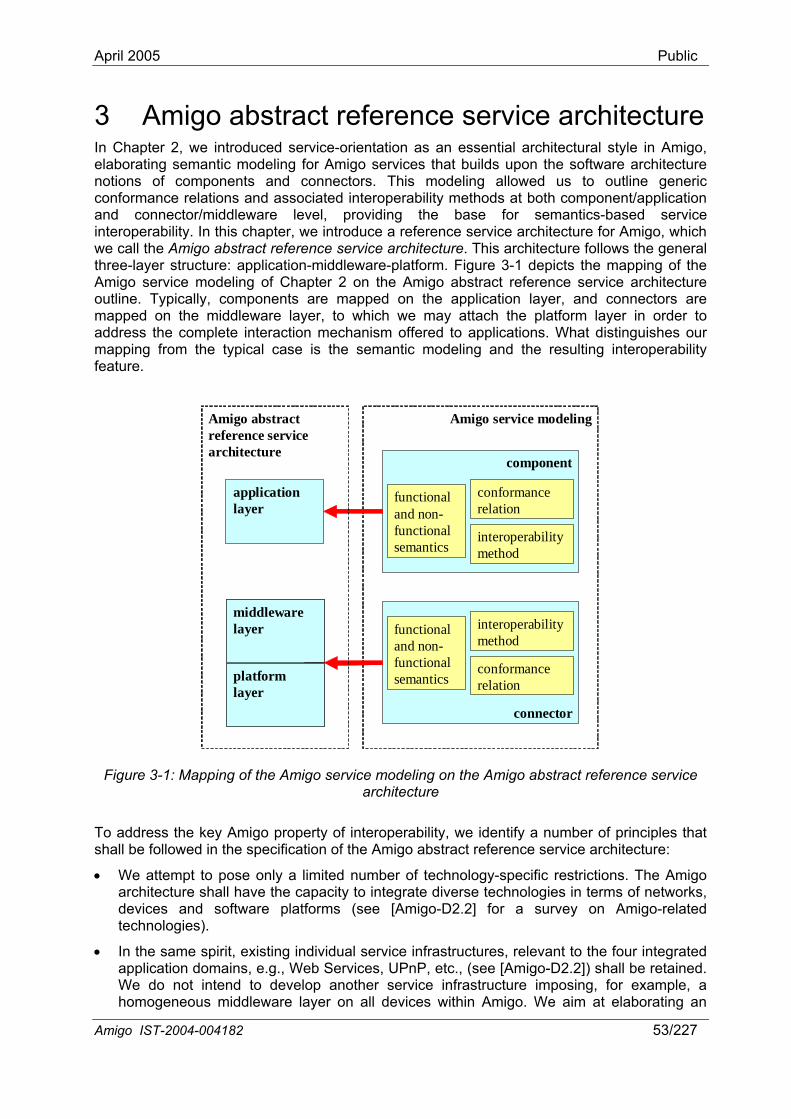
April 2005 Public
3 Amigo abstract reference service architecture In Chapter 2, we introduced service-orientation as an essential architectural style in Amigo, elaborating semantic modeling for Amigo services that builds upon the software architecture notions of components and connectors. This modeling allowed us to outline generic conformance relations and associated interoperability methods at both component/application and connector/middleware level, providing the base for semantics-based service interoperability. In this chapter, we introduce a reference service architecture for Amigo, which we call the Amigo abstract reference service architecture. This architecture follows the general three-layer structure: application-middleware-platform. Figure 3-1 depicts the mapping of the Amigo service modeling of Chapter 2 on the Amigo abstract reference service architecture outline. Typically, components are mapped on the application layer, and connectors are mapped on the middleware layer, to which we may attach the platform layer in order to address the complete interaction mechanism offered to applications. What distinguishes our mapping from the typical case is the semantic modeling and the resulting interoperability feature.
Amigo service modeling
applicationlayer
component
connector
functional and non-functionalsemantics
functional and non-functionalsemantics
middlewarelayer
platformlayer
middlewarelayer
platformlayer
conformance relation
conformance relation
interoperability method
interoperability method
Amigo abstractreference servicearchitecture
Figure 3-1: Mapping of the Amigo service modeling on the Amigo abstract reference service architecture
To address the key Amigo property of interoperability, we identify a number of principles that shall be followed in the specification of the Amigo abstract reference service architecture:
• We attempt to pose only a limited number of technology-specific restrictions. The Amigo architecture shall have the capacity to integrate diverse technologies in terms of networks, devices and software platforms (see [Amigo-D2.2] for a survey on Amigo-related technologies).
• In the same spirit, existing individual service infrastructures, relevant to the four integrated application domains, e.g., Web Services, UPnP, etc., (see [Amigo-D2.2]) shall be retained. We do not intend to develop another service infrastructure imposing, for example, a homogeneous middleware layer on all devices within Amigo. We aim at elaborating an
Amigo IST-2004-004182 53/227
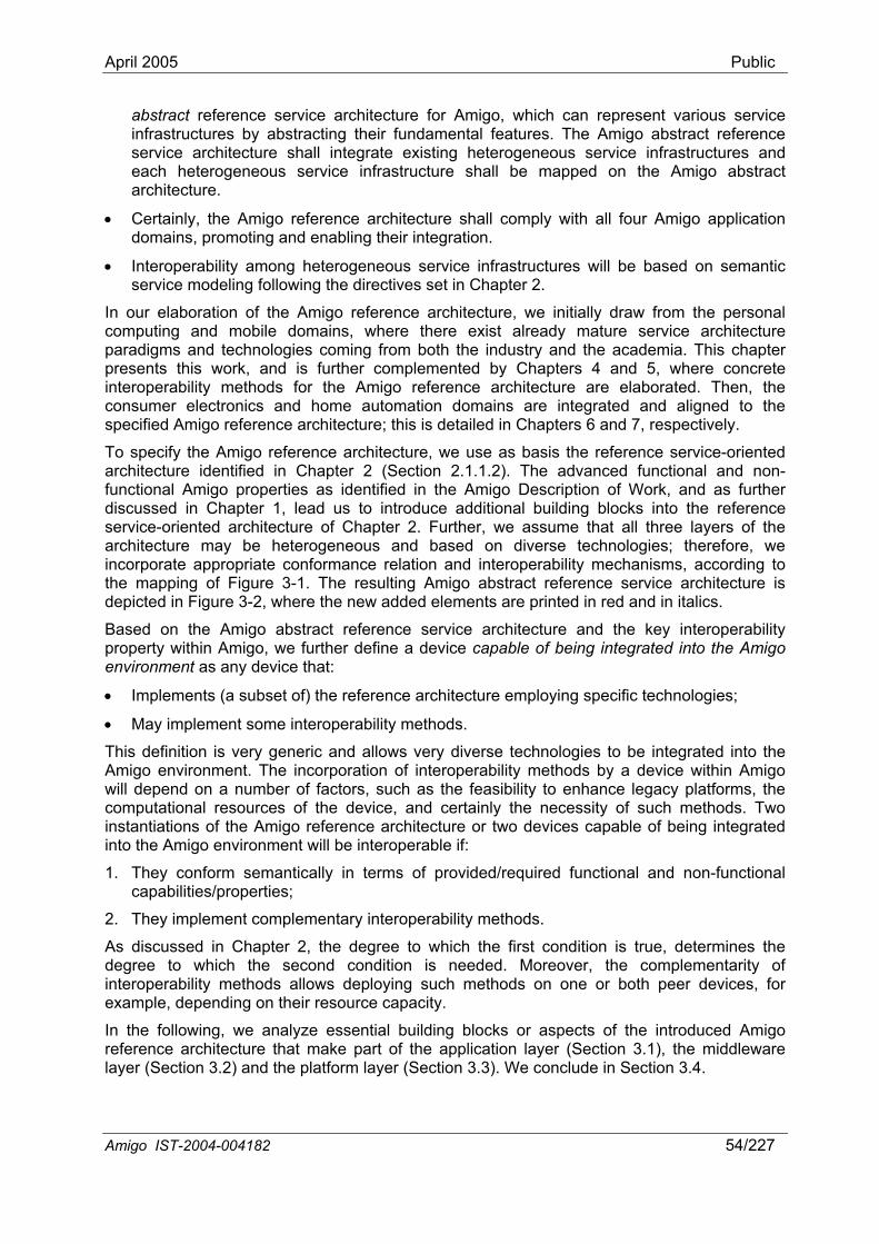
April 2005 Public
abstract reference service architecture for Amigo, which can represent various service infrastructures by abstracting their fundamental features. The Amigo abstract reference service architecture shall integrate existing heterogeneous service infrastructures and each heterogeneous service infrastructure shall be mapped on the Amigo abstract architecture.
• Certainly, the Amigo reference architecture shall comply with all four Amigo application domains, promoting and enabling their integration.
• Interoperability among heterogeneous service infrastructures will be based on semantic service modeling following the directives set in Chapter 2.
In our elaboration of the Amigo reference architecture, we initially draw from the personal computing and mobile domains, where there exist already mature service architecture paradigms and technologies coming from both the industry and the academia. This chapter presents this work, and is further complemented by Chapters 4 and 5, where concrete interoperability methods for the Amigo reference architecture are elaborated. Then, the consumer electronics and home automation domains are integrated and aligned to the specified Amigo reference architecture; this is detailed in Chapters 6 and 7, respectively.
To specify the Amigo reference architecture, we use as basis the reference service-oriented architecture identified in Chapter 2 (Section 2.1.1.2). The advanced functional and non-functional Amigo properties as identified in the Amigo Description of Work, and as further discussed in Chapter 1, lead us to introduce additional building blocks into the reference service-oriented architecture of Chapter 2. Further, we assume that all three layers of the architecture may be heterogeneous and based on diverse technologies; therefore, we incorporate appropriate conformance relation and interoperability mechanisms, according to the mapping of Figure 3-1. The resulting Amigo abstract reference service architecture is depicted in Figure 3-2, where the new added elements are printed in red and in italics.
Based on the Amigo abstract reference service architecture and the key interoperability property within Amigo, we further define a device capable of being integrated into the Amigo environment as any device that:
• Implements (a subset of) the reference architecture employing specific technologies;
• May implement some interoperability methods.
This definition is very generic and allows very diverse technologies to be integrated into the Amigo environment. The incorporation of interoperability methods by a device within Amigo will depend on a number of factors, such as the feasibility to enhance legacy platforms, the computational resources of the device, and certainly the necessity of such methods. Two instantiations of the Amigo reference architecture or two devices capable of being integrated into the Amigo environment will be interoperable if:
1. They conform semantically in terms of provided/required functional and non-functional capabilities/properties;
2. They implement complementary interoperability methods.
As discussed in Chapter 2, the degree to which the first condition is true, determines the degree to which the second condition is needed. Moreover, the complementarity of interoperability methods allows deploying such methods on one or both peer devices, for example, depending on their resource capacity.
In the following, we analyze essential building blocks or aspects of the introduced Amigo reference architecture that make part of the application layer (Section 3.1), the middleware layer (Section 3.2) and the platform layer (Section 3.3). We conclude in Section 3.4.
Amigo IST-2004-004182 54/227
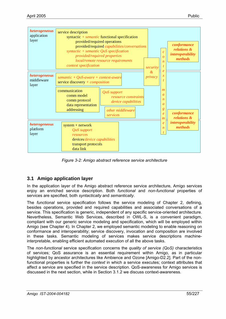
April 2005 Public
Amigo IST-2004-004182 55/227
heterogeneousmiddlewarelayer
heterogeneousplatformlayer
communicationcomm modelcomm protocoldata representationaddressing
heterogeneousapplicationlayer
service descriptionsyntactic functional specification
provided/required operationsprovided/required
+ semantic
capabilities/conversationssyntactic + semantic QoS specification
provided/required propertieslocal/remote resource requirements
context specification
system + network
devicestransport protocolsdata link
QoS supportresources
/device capabilities
QoS supportresource constraintsdevice capabilities
other middlewareservices
security&
privacy
context
management
semantic + QoS-aware + context-aware+ compositionservice discovery
conformance relations &
interoperabilitymethods
conformance relations &
interoperabilitymethods
Figure 3-2: Amigo abstract reference service architecture
3.1 Amigo application layer In the application layer of the Amigo abstract reference service architecture, Amigo services enjoy an enriched service description. Both functional and non-functional properties of services are specified, both syntactically and semantically.
The functional service specification follows the service modeling of Chapter 2, defining, besides operations, provided and required capabilities and associated conversations of a service. This specification is generic, independent of any specific service-oriented architecture. Nevertheless, Semantic Web Services, described in OWL-S, is a convenient paradigm, compliant with our generic service modeling and specification, which will be employed within Amigo (see Chapter 4). In Chapter 2, we employed semantic modeling to enable reasoning on conformance and interoperability; service discovery, invocation and composition are involved in these tasks. Semantic modeling of services makes service descriptions machine-interpretable, enabling efficient automated execution of all the above tasks.
The non-functional service specification concerns the quality of service (QoS) characteristics of services; QoS assurance is an essential requirement within Amigo, as in particular highlighted by ancestor architectures like Ambience and Ozone [Amigo-D2.2]. Part of the non-functional properties is further the context in which a service executes; context attributes that affect a service are specified in the service description. QoS-awareness for Amigo services is discussed in the next section, while in Section 3.1.2 we discuss context-awareness.
April 2005 Public
3.1.1 QoS-aware services The QoS specification of Amigo services defines the QoS properties provided and required by the services. QoS properties are key information for dynamically selecting the services that best meet the user needs. If there are several services in a service registry with similar functionalities, then QoS requirements enable a finer search. The QoS aspect becomes even more important in the process of composition of various services with different QoS attributes and requirements. The QoS specification shall further incorporate the local and remote resource requirements of services. QoS versus resource consumption is a critical trade-off in the Amigo environment. Besides, the QoS specification will be both syntactic and semantic.
On the one hand, the syntactic part will define QoS dimensions and associated metrics. This definition shall: (i) allow description of both quantitative (e.g., service latency) and qualitative (e.g., CPU scheduling mechanism) QoS attributes [SCD+97]; (ii) be declarative in nature, that is, specify only what is required, but not how the requirements are implemented [AuCH98]. In addition, although more QoS parameters yield a more detailed description, the gain has to be put against the increased overhead. Usually, dominant QoS properties of systems may be captured with a small number of attributes [DiLS00]. In the work presented in [LiIs04], key QoS attributes for mobile systems have been identified. The work described in [ITLS04] has, further, pinpointed essential non-functional features of the mobile environment. These efforts addressing mobile environments can be useful to Amigo, as the Amigo home environment incorporates several of their features. From the above research efforts, the following categories of QoS information may be identified:
• Runtime-related QoS may include scalability (limit of concurrent requests), performance (in terms of response time, latency, throughput), reliability, accuracy, availability.
• Transaction-support QoS might be characterized by the integrity of the data operated on by service transactions.
• Configuration- and cost-related QoS may include regulatory, supported standards, stability/changing cycle, cost (per request, per volume of data), completeness (difference in specified and implemented set of features), timeliness (freshness of information).
• Security-related QoS measures the trustworthiness and security mechanisms implemented (authentication, authorization, confidentiality, trust, data encryption, etc.).
On the other hand, adding semantics to the QoS specification will enable non-functional interoperability, in a way similar to functional interoperability. Semantic description of QoS can be achieved through a QoS ontology, which will allow providers and consumers to express policies and preferences, respectively. The service profile in OWL-S can be used for this purpose. DAML-QoS [ZhCL04] is an attempt to provide a QoS ontology to complement OWL-S service description with enhanced QoS representation capabilities. In Chapter 2, we pointed out our future working on semantic modeling of the non-functional behavior of services within Amigo.
Finally, with regard to services offered to the Amigo home from outside, service providers may commit to providing a certain level of quality of service. This commitment is formalized using Service Level Agreements (SLAs) [WSS+01]. SLAs can be considered as binding contracts that are agreed upon between service providers and service requesters.
3.1.2 Context-aware services The term ‘context’ is overloaded with a wide variety of meanings, depending on the purpose of the particular application and/or the specific research community standpoint. In Amigo, we adopt the following general definition of context proposed in [DeSA01], extending it to include device-to-device communication.
Amigo IST-2004-004182 56/227

April 2005 Public
“…Context is any information that can be used to characterize the situation of an entity. An entity is a person, place, or object that is considered relevant to the interaction between a user and an application, including the user and application themselves.”
In [ScAW94], the following categories of context are defined:
• Device context: contextual information related to devices. Examples are available memory, computation power, networks (and their quality), codecs, etc.
• User context: context information that describes a person, further decomposing into: o Personal context: health, mood, schedule, activity, etc., o Application context: email received, Web sites visited, preferences, etc. o Social contexts: group activity, social relationship, people nearby etc.
• Physical context: contextual information related to the physical environment of an entity (device, room, building, user). Examples are location, time, weather, altitude, light.
The classification of context, as relevant to the Amigo system, will be extensively investigated within the project. This is in particular key issue of Task 2.2 (Deliverable D2.3) and Work Package WP4, which will investigate context management in intelligent user services.
Context information is usually dynamic and may be retrieved from appropriate sources when needed, or may be collected and organized by a specialized context management middleware service. Nevertheless, context management mechanisms span all three layers of the enriched architecture. The role of the Amigo context management is, more specifically, to acquire information coming from various sources, ranging from physical sensors to Internet applications, combine these pieces of information into "context information", and make this context information available to Amigo services, so as to enable these services to become context-aware, i.e., to support context-aware service discovery, context-aware service composition etc. To this purpose, a common language must be agreed upon so as to describe context information. We will base our modeling of context information on an ontology of context. OWL will be used to model context information and queries such as:
• Context information (e.g., the temperature in room x is 21°); • Context queries (e.g., what is the temperature in room x? where is device y?); • Context conditions (e.g., if the temperature is above 30°, post an event or trigger an
action).
In order to enable context-aware service discovery, service descriptions shall include contextual information, such as a “context of use” that describes contextual conditions in which the service can be used. The “context of use” participates in the description of the service functionality, as “what the service does” may depend on the context in which it is used. Additional context constraints can also be provided to improve the quality of retrieved results in the matching process of service discovery. Providing information about the contextual conditions in the service description enables service discovery to handle more abstract queries. For instance, a service requester might look for a service to display data for a particular user. When answering this request, the discovery service should consider the user's location to select appropriate services. Through contextual conditions of use, the service description gives the hint that the intended user of the service should be in the same room as the device that provides this service. The discovery service has to take this information into account during the matching/selection process, even if the original request didn't explicitly suggested selecting a service located in a given room (the requester specified only that this service should be available for a given user). Location is an example of contextual information that often impacts the selection of services in an ambient intelligence environment. Depending on services, several other contextual pieces of information (noise level, light, user activity...) will be relevant. Context conditions can be easily included in an OWL-S service description as a particular kind of preconditions. The service discovery employs the context management service to check these specific conditions and decide whether the service can be used in the current context.
Amigo IST-2004-004182 57/227
April 2005 Public
3.2 Amigo middleware layer In the middleware layer of the Amigo abstract reference service architecture, middleware services of the reference service-oriented architecture of Chapter 2 are now enhanced or new middleware services are added:
• Service communication provides the core mechanism already discussed in Chapter 2.
• Service discovery is enhanced to reflect the enriched service description. Thus, service discovery shall be semantics-based, QoS-aware and context-aware. Semantics enable service discovery based on reasoning about the functional capabilities, as well as the QoS properties and resource requirements of services. Service discovery shall both optimize resource consumption on resource-constrained devices and satisfy users’ requirements with respect to perceived QoS. As already mentioned, the QoS versus resource consumption trade-off shall be taken into account. Context, further, shall be considered in service discovery and selection, as discussed in the previous section. Service discovery is a key functionality in the dynamic, diverse Amigo environment; therefore, in Section 3.2.1, we extensively discuss essential aspects of service discovery in Amigo.
• Service discovery is closely related to service composition. In the Amigo environment, services are composed to provide new more complex services. In such an environment, the composition of services becomes extremely hard as it shall: (i) be dynamic, according to available services at the specific time and place; (ii) satisfy the functional and QoS requirements in an effective way within the bounds posed by the resource constraints of mobile devices; (iii) take into account context; and (iv) accommodate the heterogeneity of technologies. Thus, employing service discovery, service composition shall be semantics-based, QoS-aware and context-aware.
• As already pointed out, QoS support is a major requirement in Amigo and is involved in various aspects of the Amigo reference architecture. We have discussed so far application-level QoS as a set of service properties. QoS may further be enforced or enhanced at middleware level by dynamically integrating specialized middleware components into the communication path between services [FSAK01, IST+04]. These middleware components may be dynamically discovered and retrieved according to middleware-level QoS requirements. Using the software architecture terminology of Chapter 2, this is another case of connector customization. In this way, properties such as reliability or performance may be enforced or enhanced at middleware level. This dynamic integration of middleware components shall make part of the service composition mechanism discussed above; in this way, the required middleware-level QoS for a service is enforced upon dynamic service composition. In the IST Ozone project, connector customization between mobile Web services was elaborated23. Same as in application-level QoS, middleware-level QoS support shall take into account device capabilities and resource constraints.
• Security and privacy is another fundamental requirement in the Amigo environment. Special conditions characterize this networked home environment, such as devices with very diverse capabilities; services with various levels of required security and privacy; and the concern not to upset the feeling of home comfort, with obtrusive, complex security mechanisms, without, however, compromising security and privacy itself. These conditions shall be given special attention in supporting security and privacy in Amigo. Security and privacy mechanisms span both the middleware and application layer of the enriched architecture. Our vision of security and privacy within Amigo is detailed in Chapter 8.
• A number of other middleware services aiming at satisfying additional Amigo requirements are incorporated in the middleware layer. Such services shall support content distribution,
23 http://www-rocq.inria.fr/arles/download/ozone/
Amigo IST-2004-004182 58/227
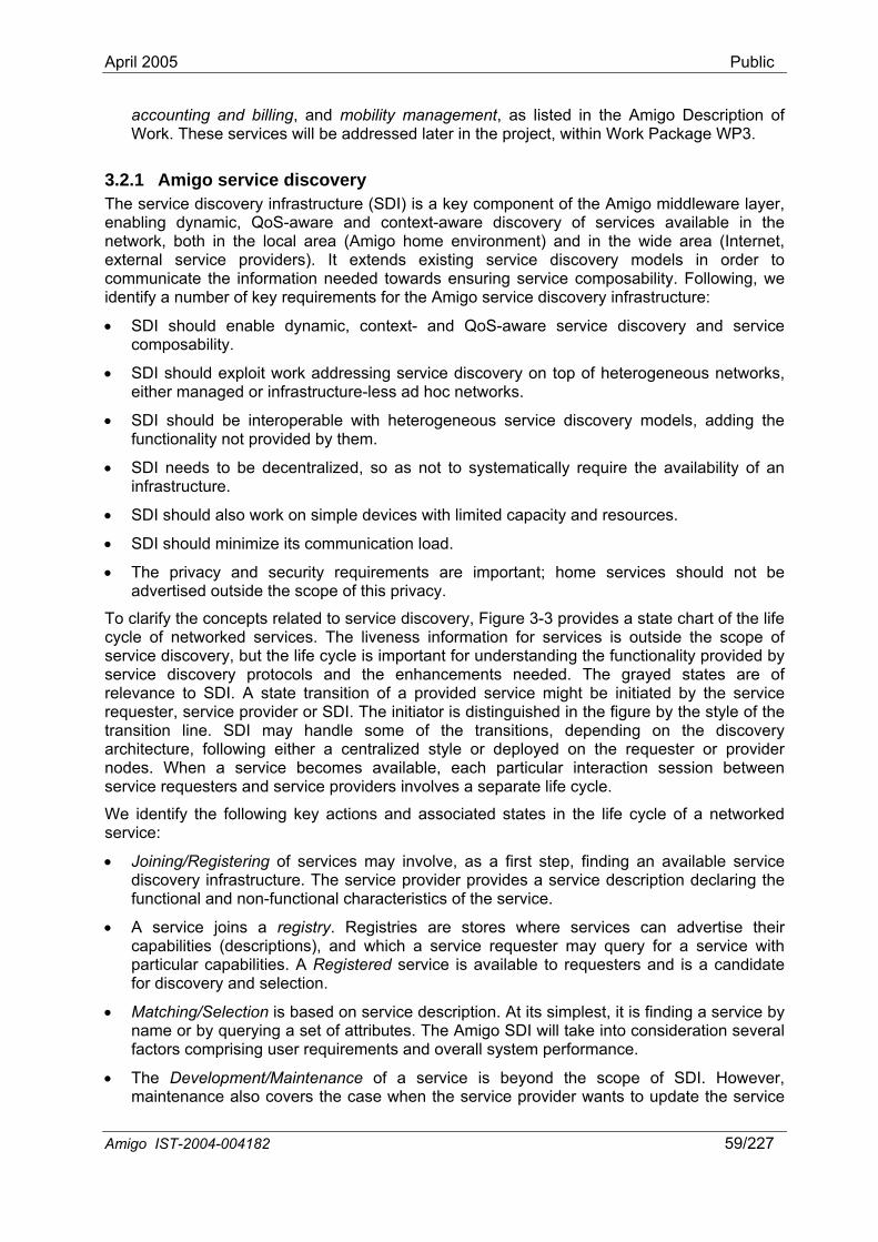
April 2005 Public
accounting and billing, and mobility management, as listed in the Amigo Description of Work. These services will be addressed later in the project, within Work Package WP3.
3.2.1 Amigo service discovery The service discovery infrastructure (SDI) is a key component of the Amigo middleware layer, enabling dynamic, QoS-aware and context-aware discovery of services available in the network, both in the local area (Amigo home environment) and in the wide area (Internet, external service providers). It extends existing service discovery models in order to communicate the information needed towards ensuring service composability. Following, we identify a number of key requirements for the Amigo service discovery infrastructure:
• SDI should enable dynamic, context- and QoS-aware service discovery and service composability.
• SDI should exploit work addressing service discovery on top of heterogeneous networks, either managed or infrastructure-less ad hoc networks.
• SDI should be interoperable with heterogeneous service discovery models, adding the functionality not provided by them.
• SDI needs to be decentralized, so as not to systematically require the availability of an infrastructure.
• SDI should also work on simple devices with limited capacity and resources.
• SDI should minimize its communication load.
• The privacy and security requirements are important; home services should not be advertised outside the scope of this privacy.
To clarify the concepts related to service discovery, Figure 3-3 provides a state chart of the life cycle of networked services. The liveness information for services is outside the scope of service discovery, but the life cycle is important for understanding the functionality provided by service discovery protocols and the enhancements needed. The grayed states are of relevance to SDI. A state transition of a provided service might be initiated by the service requester, service provider or SDI. The initiator is distinguished in the figure by the style of the transition line. SDI may handle some of the transitions, depending on the discovery architecture, following either a centralized style or deployed on the requester or provider nodes. When a service becomes available, each particular interaction session between service requesters and service providers involves a separate life cycle.
We identify the following key actions and associated states in the life cycle of a networked service:
• Joining/Registering of services may involve, as a first step, finding an available service discovery infrastructure. The service provider provides a service description declaring the functional and non-functional characteristics of the service.
• A service joins a registry. Registries are stores where services can advertise their capabilities (descriptions), and which a service requester may query for a service with particular capabilities. A Registered service is available to requesters and is a candidate for discovery and selection.
• Matching/Selection is based on service description. At its simplest, it is finding a service by name or by querying a set of attributes. The Amigo SDI will take into consideration several factors comprising user requirements and overall system performance.
• The Development/Maintenance of a service is beyond the scope of SDI. However, maintenance also covers the case when the service provider wants to update the service
Amigo IST-2004-004182 59/227
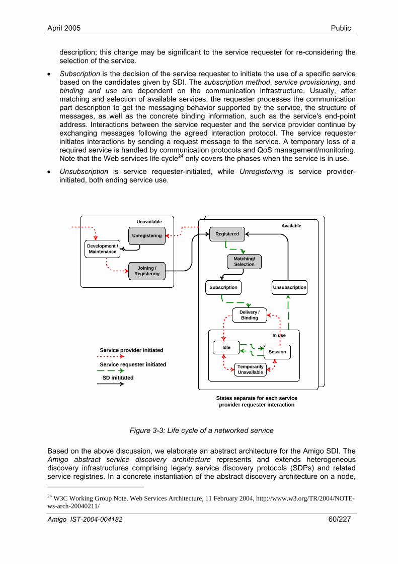
April 2005 Public
description; this change may be significant to the service requester for re-considering the selection of the service.
• Subscription is the decision of the service requester to initiate the use of a specific service based on the candidates given by SDI. The subscription method, service provisioning, and binding and use are dependent on the communication infrastructure. Usually, after matching and selection of available services, the requester processes the communication part description to get the messaging behavior supported by the service, the structure of messages, as well as the concrete binding information, such as the service's end-point address. Interactions between the service requester and the service provider continue by exchanging messages following the agreed interaction protocol. The service requester initiates interactions by sending a request message to the service. A temporary loss of a required service is handled by communication protocols and QoS management/monitoring. Note that the Web services life cycle24 only covers the phases when the service is in use.
• Unsubscription is service requester-initiated, while Unregistering is service provider-initiated, both ending service use.
Available
In use
Subscription
Matching/Selection
Development /Maintenance
SessionIdle
Delivery /Binding
Joining /Registering
Unavailable
Registered
TemporarilyUnavailable
Service provider initiated
Service requester initiated
SD inititated
Unregistering
Unsubscription
States separate for each serviceprovider requester interaction
Figure 3-3: Life cycle of a networked service
Based on the above discussion, we elaborate an abstract architecture for the Amigo SDI. The Amigo abstract service discovery architecture represents and extends heterogeneous discovery infrastructures comprising legacy service discovery protocols (SDPs) and related service registries. In a concrete instantiation of the abstract discovery architecture on a node, 24 W3C Working Group Note. Web Services Architecture, 11 February 2004, http://www.w3.org/TR/2004/NOTE-ws-arch-20040211/
Amigo IST-2004-004182 60/227
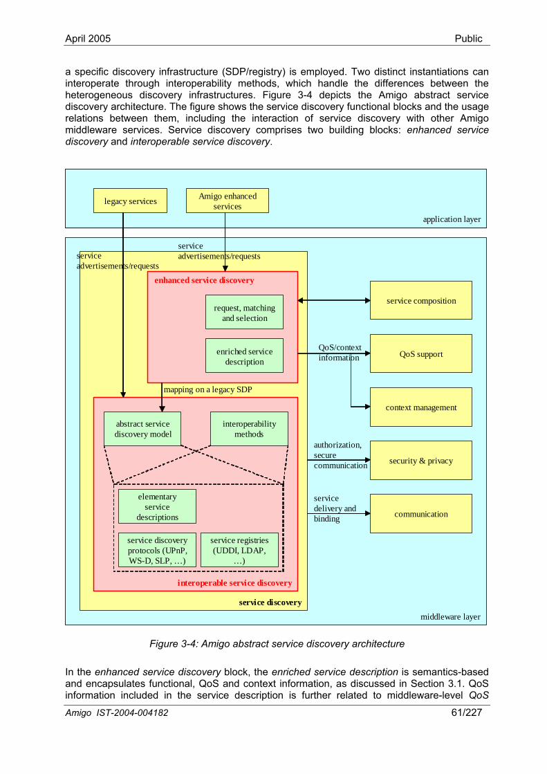
April 2005 Public
a specific discovery infrastructure (SDP/registry) is employed. Two distinct instantiations can interoperate through interoperability methods, which handle the differences between the heterogeneous discovery infrastructures. Figure 3-4 depicts the Amigo abstract service discovery architecture. The figure shows the service discovery functional blocks and the usage relations between them, including the interaction of service discovery with other Amigo middleware services. Service discovery comprises two building blocks: enhanced service discovery and interoperable service discovery.
application layer
Amigo enhanced serviceslegacy services
middleware layer
service discovery
enhanced service discovery
interoperable service discovery
elementary service
descriptions
service discovery protocols (UPnP, WS-D, SLP, …)
service registries (UDDI, LDAP,
…)
abstract service discovery model
interoperability methods
enriched service description
request, matching and selection
service composition
QoS support
context management
security & privacy
communication
service advertisements/requests
service advertisements/requests
QoS/context information
service delivery and binding
authorization, secure communication
mapping on a legacy SDP
Figure 3-4: Amigo abstract service discovery architecture
In the enhanced service discovery block, the enriched service description is semantics-based and encapsulates functional, QoS and context information, as discussed in Section 3.1. QoS information included in the service description is further related to middleware-level QoS
Amigo IST-2004-004182 61/227
April 2005 Public
support. Based on the service description, a context-aware [Broe04] and QoS-aware request, matching and selection mechanism provides the principal functionality of service discovery; this is further discussed in Section 3.2.1.1. To incorporate dynamic context information, the matching mechanism interacts with the context management service.
The interoperable service discovery block represents legacy service discovery infrastructures, each prescribing an elementary service description, a SDP and a service registry. Abstraction of heterogeneous discovery infrastructures is enabled by the abstract service discovery model. This model integrates diverse models of publishing and querying information about Amigo services; this is further discussed in Section 3.2.1.2. Based on the abstract service discovery model, appropriate interoperability methods can be built to interconnect heterogeneous discovery infrastructures. More specifically, interoperability between two discovery infrastructures can be realized by mapping both on the abstract discovery model and translating from one to the other by passing through this common representation. This translation concerns all the elements of the discovery infrastructures, i.e., the elementary service description, the SDP and the service registry. This approach is thoroughly discussed and elaborated in Chapter 5.
Figure 3-5: Example service discovery topology in the Amigo environment
The interoperable service discovery provides an interoperable discovery infrastructure to the enhanced service discovery, allowing the latter to employ any legacy discovery infrastructure. This is accomplished through the abstract, common discovery representation embodied by the abstract service discovery model, and through the related interoperability methods. Thus, the enhanced service discovery always accesses this uniform discovery representation, independently of the underlying legacy discovery infrastructure, which may vary.
Amigo IST-2004-004182 62/227
A device within the Amigo environment may support enhanced service discovery. In this case, the device instantiates the full abstract discovery architecture. Services on this device interact with the enhanced service discovery block for service advertisements/requests. Nevertheless,
April 2005 Public
a legacy device within Amigo may merely support legacy service discovery. In this case, the device instantiates only part of the abstract discovery architecture, i.e., the interoperable service discovery block. Services on this device interact with this block for service advertisements/requests. An example of a service discovery topology in the Amigo environment including both enhanced and legacy devices is illustrated in Figure 3-5. Amigo discovery in the figure may be either the full enhanced service discovery or only the interoperable service discovery.
3.2.1.1 Amigo enhanced service discovery In service discovery, the service requester has a need for a service, and there is a set of advertised services from which this need has to be satisfied. The service discovery process compares service advertisements provided by service providers with requests provided by service requesters and tries to match them and, if required, automatically select the most suitable candidate. This is the role of the request, matching and selection mechanism. The Amigo enhanced service discovery employs such a mechanism that is based on the enriched service description. Thus, request, matching and selection of services is done based on functional and non-functional properties, as declared in the service description, and situational context, or monitored QoS information.
The requesting, matching and selection is strongly associated with the information retrieval (IR) area. In the computer-centered view, the IR problem consists mainly of building up efficient indexes, processing user queries with high performance, and developing ranking algorithms that improve the quality of the answer set [BYRR99]. Effective service retrieval in service discovery is directly affected both by the service request representation and by the logical view of the advertised service. In information retrieval, there are two key quality measurements, which can also be applied in service discovery. A retrieval service should provide both high recall – that is, it should retrieve all the items a user is interested in – and high precision – that is, it should retrieve only the items a requester is interested in. Four types of service retrieval approaches are distinguished in [KlB04a]. These are keyword-based, table-based, concept-based, and deductive approaches. Similarly, those approaches may be used in Amigo SDI for interoperable and enhanced service discovery functionality.
• In the keyword-based approach, most search engines look for items that contain the keywords of the request (e.g., UDDI25). Such approaches are notoriously prone to both low precision and imperfect recall.
• A table-based approach describes both items and queries as tables. A table-based service model consists of attribute-value pairs that capture service properties, typically including its name, description, inputs and outputs, as well as some performance-related attributes, such as cost and execution time. Many existing service discovery technologies (e.g., Jini) use the table-based approach.
• The concept-based approach provides the requester with ontologies for capturing service request semantics, thereby enabling service discovery based on rich context information, rather than on keywords. This approach can give increased precision and recall.
• Deductive approaches express service request semantics formally, using logic. The service discovery process with this method may be highly complex and therefore operate slowly.
The matching process matches existing service descriptions with requester’s needs. It is obvious that in Amigo service discovery, matching should not rely only on keyword- or table-based search; instead, the concept-based approach should be supported. Semantic and syntactic information about each attribute in the service request and advertisement must be 25 Universal Description, Discovery, and Integration of Business for the Web, October 2001. http://www.uddi.org.
Amigo IST-2004-004182 63/227
April 2005 Public
taken into consideration. Equality of concepts’ names (i.e., syntax) does not necessarily mean equality of their semantics. Since advertiser and requester may have different knowledge about the same service, the matching process should first examine semantic equivalence and then syntactic equivalence between service capabilities and requester’s needs [PiTB03, PKPS02]. Semantic matching has to precede syntactic matching, as it is necessary to assure that both request and advertisement address the same subject area. Then an optimization must take place in order to return the most highly-rated matches and present them in an appropriate way depending on the context.
In practice, it is hard to expect advertisements and requests to be equivalent, or that an existing service would exactly fulfill the requester’s needs. Thus, several matching algorithms have been proposed in the literature that take into account semantic aspects of the service description to accomplish the problem with capability matching. The approach described by [PKPS02] is one of the most used. Specifically in this approach, an advertisement matches a request when all outputs and inputs of the advertisement and all outputs and inputs of the request are matched, respectively. There are four degrees of matching: exact, plug in, subsumes, and fail. The selection is based on the highest score in output matching. An input matching is used only as a secondary score to sort between equally scoring outputs. In Chapter 4, we employ a modified version of this algorithm in semantic matching, selection and dynamic composition of multiple services within Amigo.
The non-functional characteristics of the service, such as QoS, can assist when reasoning about several services with similar capabilities. QoS requirements can be used as a filter in the matchmaker to ensure that the selected service satisfies the requester’s need for the quality level of service.
Also, the contextual criteria enable to refine a request by providing information on the context in which the service is needed. This feature is key in a situated, ambient environment, as the first matching stage can find lots of services providing the same functionality, based on semantic matching (e.g., displaying an image), whereas only one of these services may really be relevant, when considering contextual information (e.g., the user's location). Thus, a request should not only contain a description of the raw functionality of the service to be found, but should also provide information about how this service must answer to environmental and contextual requirements. A requester can thus express contextual criteria to influence the service matching process. Two types of criteria are considered: constraints and preferences. Constraints define a binary filter: candidate services that do not meet the constraints must be excluded by the matching process. Preferences enable the discovery service to sort candidate services among those that satisfy the constraints. Preferences may have a simple expression (e.g., sort results according to the distance to the user) or express trade-offs between several criteria. For instance, a requester might want a printing service that is as close as possible to the user, and that will be available as soon as possible. The best choice might not be the closest nor the least loaded printer, but a trade-off between these criteria.
Context awareness is closely related to QoS-based service selection. The offered QoS may depend on context, i.e., on current situation/environment properties, and capabilities of device used. In some cases, the context can be viewed as one of the constraints in successful service selection for a particular QoS level (e.g., the user’s location might be a constraint in the selection of appropriate screen size of a displaying device). In some scenarios, a trade-off between context and QoS parameters (e.g., through a QoS ontology, context ontology and their relation) must be considered for the appropriate service selection. An example of such a scenario can be a person viewing some private photos. Depending on the context (e.g., if somebody else is present in the room, privacy level) a small PDA or a big screen device (QoS) can be selected for viewing the photos.
The elaboration of the Amigo enhanced service discovery is part of our future work in Amigo; it will specifically be addressed in Task 3.3 on discovery infrastructure of Work package WP3.
Amigo IST-2004-004182 64/227
April 2005 Public
3.2.1.2 Amigo interoperable service discovery The Amigo interoperable service discovery represents and abstracts existing service discovery infrastructures by means of the abstract service discovery model, so as to both enable interoperability between them and provide an infrastructure-independent representation of them to the enhanced service discovery. In this section, we discuss several features of service discovery infrastructures, which shall be abstracted by the abstract discovery model. In the inverse direction, we make a number of suggestions for a discovery model appropriate for the Amigo environment, which could lead to favoring specific discovery infrastructures for Amigo. A more concrete discussion on abstracting features of discovery infrastructures is conducted in Chapter 5, as part of the design of dedicated interoperability methods.
By means of the discovery infrastructure, service providers need to be able to publish the availability and proper properties of their services to the potential service users. There are three approaches for achieving this objective26:
• A centralized registry or repository is an authoritative, centrally controlled store of service, in which there is a service broker who plays the role of registering and categorizing published services, and providing search services.
• In contrast with a centralized registry, an index is a compilation or guide to information that exists elsewhere. It is not authoritative and does not centrally control the information that it references.
• A peer-to-peer (P2P) scheme provides an alternative to centralized registries, allowing services to discover each other dynamically. Decentralized registries may be maintained by peer nodes.
Because of their respective advantages and disadvantages, P2P systems, indexes and centralized registries strike different trade-offs that make them appropriate in different situations. P2P systems are more appropriate in dynamic environments, in which proximity naturally limits the need to propagate requests, such as in ubiquitous computing. Centralized registries may be more appropriate in more static or controlled environments, where information does not change frequently. Indexes may be more appropriate in situations that must scale well and accommodate competition and diversity in indexing strategies. Ideally, service discovery should have the ability to consolidate the results of queries that span more than a single registry or index, and make them appear more like coming from a single discovery facility.
The Amigo service discovery architecture needs to be decentralized, so as not to systematically require the availability of an infrastructure. Nevertheless, the limited capacity (memory and processing power) of devices within the Amigo environment may pose constraints on their capability to support enhanced service discovery, thus, implementing it in a purely decentralized style may be difficult. Certain discovery infrastructures support dynamic adaptation to the current distribution of the discovery architecture. For example, WS-Discovery27 provides a model where initially a decentralized mode is used, but if a registry is available, it sends a reply message to the multicast of the requester, and the requester starts using the registry, possibly employing a different discovery protocol. A similar model is used for SLP directory agents [GPVD99].
A further classification of service discovery is – with respect to the role of service requesters and service providers – into active service discovery and passive service discovery.
26 W3C Working Group Note. Web Services Architecture, 11 February 2004, http://www.w3.org/TR/2004/NOTE-ws-arch-20040211/ 27 msdn.microsoft.com/ws/2004/10/ws-discovery/
Amigo IST-2004-004182 65/227
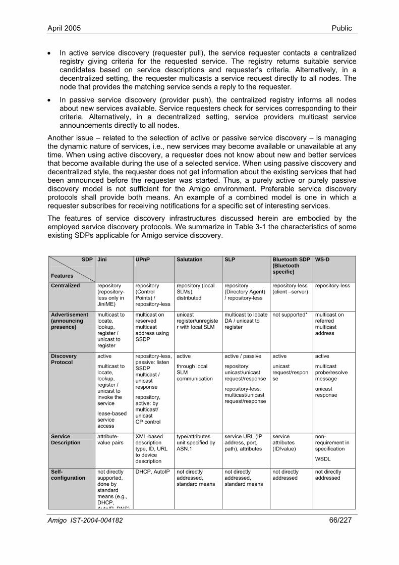
April 2005 Public
• In active service discovery (requester pull), the service requester contacts a centralized registry giving criteria for the requested service. The registry returns suitable service candidates based on service descriptions and requester’s criteria. Alternatively, in a decentralized setting, the requester multicasts a service request directly to all nodes. The node that provides the matching service sends a reply to the requester.
• In passive service discovery (provider push), the centralized registry informs all nodes about new services available. Service requesters check for services corresponding to their criteria. Alternatively, in a decentralized setting, service providers multicast service announcements directly to all nodes.
Another issue – related to the selection of active or passive service discovery – is managing the dynamic nature of services, i.e., new services may become available or unavailable at any time. When using active discovery, a requester does not know about new and better services that become available during the use of a selected service. When using passive discovery and decentralized style, the requester does not get information about the existing services that had been announced before the requester was started. Thus, a purely active or purely passive discovery model is not sufficient for the Amigo environment. Preferable service discovery protocols shall provide both means. An example of a combined model is one in which a requester subscribes for receiving notifications for a specific set of interesting services.
The features of service discovery infrastructures discussed herein are embodied by the employed service discovery protocols. We summarize in Table 3-1 the characteristics of some existing SDPs applicable for Amigo service discovery.
SDP
Features
Jini UPnP Salutation SLP Bluetooth SDP (Bluetooth specific)
WS-D
Centralized repository (repository-less only in JiniME)
repository (Control Points) / repository-less
repository (local SLMs), distributed
repository (Directory Agent) / repository-less
repository-less (client –server)
repository-less
Advertisement (announcing presence)
multicast to locate, lookup, register / unicast to register
multicast on reserved multicast address using SSDP
unicast register/unregister with local SLM
multicast to locate DA / unicast to register
not supported* multicast on referred multicast address
Discovery Protocol
active
multicast to locate, lookup, register / unicast to invoke the service
lease-based service access
repository-less, passive: listen SSDP multicast / unicast response
repository, active: by multicast/ unicast CP control
active
through local SLM communication
active / passive
repository: unicast/unicast request/response
repository-less: multicast/unicast request/response
active
unicast request/response
active
multicast probe/resolve message
unicast response
Service Description
attribute-value pairs
XML-based description type, ID, URL to device description
type/attributes unit specified by ASN.1
service URL (IP address, port, path), attributes
service attributes (ID/value)
non-requirement in specification
WSDL
Self-configuration
not directly supported, done by standard means (e.g., DHCP, AutoIP DNS)
DHCP, AutoIP not directly addressed, standard means
not directly addressed, standard means
not directly addressed
not directly addressed
Amigo IST-2004-004182 66/227
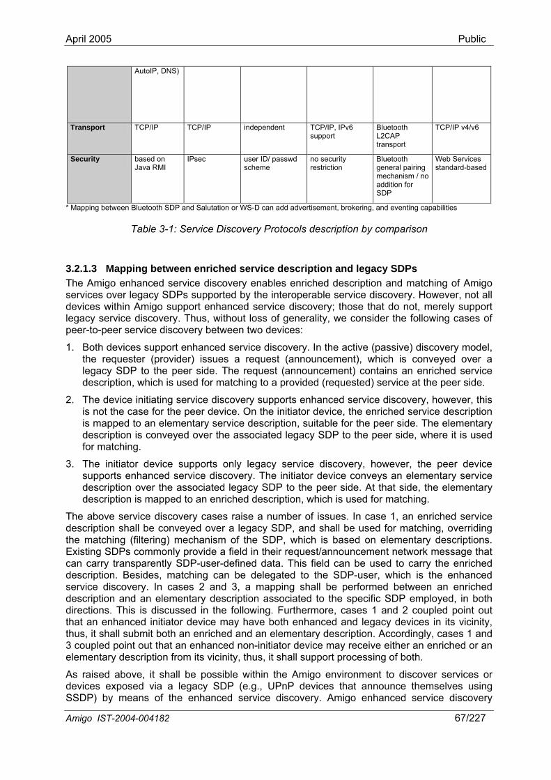
April 2005 Public
AutoIP, DNS)
Transport TCP/IP TCP/IP independent TCP/IP, IPv6 support
Bluetooth L2CAP transport
TCP/IP v4/v6
Security based on Java RMI
IPsec user ID/ passwd scheme
no security restriction
Bluetooth general pairing mechanism / no addition for SDP
Web Services standard-based
* Mapping between Bluetooth SDP and Salutation or WS-D can add advertisement, brokering, and eventing capabilities
Table 3-1: Service Discovery Protocols description by comparison
3.2.1.3 Mapping between enriched service description and legacy SDPs The Amigo enhanced service discovery enables enriched description and matching of Amigo services over legacy SDPs supported by the interoperable service discovery. However, not all devices within Amigo support enhanced service discovery; those that do not, merely support legacy service discovery. Thus, without loss of generality, we consider the following cases of peer-to-peer service discovery between two devices:
1. Both devices support enhanced service discovery. In the active (passive) discovery model, the requester (provider) issues a request (announcement), which is conveyed over a legacy SDP to the peer side. The request (announcement) contains an enriched service description, which is used for matching to a provided (requested) service at the peer side.
2. The device initiating service discovery supports enhanced service discovery, however, this is not the case for the peer device. On the initiator device, the enriched service description is mapped to an elementary service description, suitable for the peer side. The elementary description is conveyed over the associated legacy SDP to the peer side, where it is used for matching.
3. The initiator device supports only legacy service discovery, however, the peer device supports enhanced service discovery. The initiator device conveys an elementary service description over the associated legacy SDP to the peer side. At that side, the elementary description is mapped to an enriched description, which is used for matching.
The above service discovery cases raise a number of issues. In case 1, an enriched service description shall be conveyed over a legacy SDP, and shall be used for matching, overriding the matching (filtering) mechanism of the SDP, which is based on elementary descriptions. Existing SDPs commonly provide a field in their request/announcement network message that can carry transparently SDP-user-defined data. This field can be used to carry the enriched description. Besides, matching can be delegated to the SDP-user, which is the enhanced service discovery. In cases 2 and 3, a mapping shall be performed between an enriched description and an elementary description associated to the specific SDP employed, in both directions. This is discussed in the following. Furthermore, cases 1 and 2 coupled point out that an enhanced initiator device may have both enhanced and legacy devices in its vicinity, thus, it shall submit both an enriched and an elementary description. Accordingly, cases 1 and 3 coupled point out that an enhanced non-initiator device may receive either an enriched or an elementary description from its vicinity, thus, it shall support processing of both.
As raised above, it shall be possible within the Amigo environment to discover services or devices exposed via a legacy SDP (e.g., UPnP devices that announce themselves using SSDP) by means of the enhanced service discovery. Amigo enhanced service discovery
Amigo IST-2004-004182 67/227
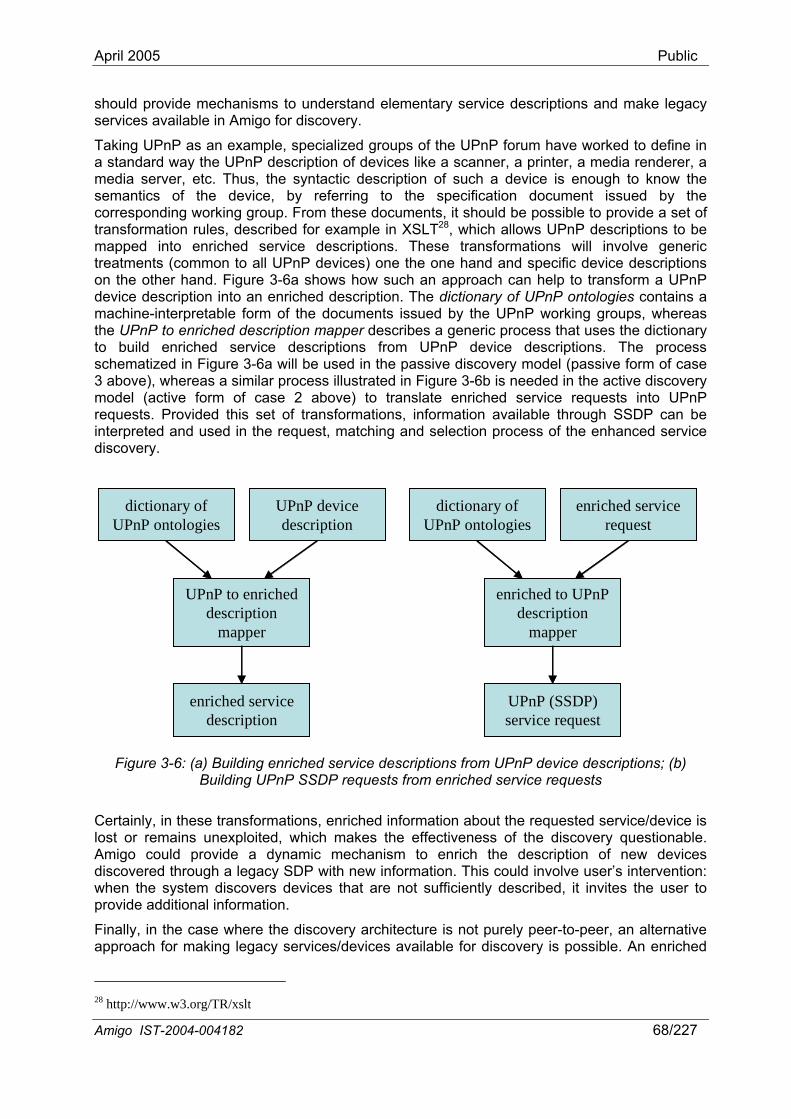
April 2005 Public
should provide mechanisms to understand elementary service descriptions and make legacy services available in Amigo for discovery.
Taking UPnP as an example, specialized groups of the UPnP forum have worked to define in a standard way the UPnP description of devices like a scanner, a printer, a media renderer, a media server, etc. Thus, the syntactic description of such a device is enough to know the semantics of the device, by referring to the specification document issued by the corresponding working group. From these documents, it should be possible to provide a set of transformation rules, described for example in XSLT28, which allows UPnP descriptions to be mapped into enriched service descriptions. These transformations will involve generic treatments (common to all UPnP devices) one the one hand and specific device descriptions on the other hand. Figure 3-6a shows how such an approach can help to transform a UPnP device description into an enriched description. The dictionary of UPnP ontologies contains a machine-interpretable form of the documents issued by the UPnP working groups, whereas the UPnP to enriched description mapper describes a generic process that uses the dictionary to build enriched service descriptions from UPnP device descriptions. The process schematized in Figure 3-6a will be used in the passive discovery model (passive form of case 3 above), whereas a similar process illustrated in Figure 3-6b is needed in the active discovery model (active form of case 2 above) to translate enriched service requests into UPnP requests. Provided this set of transformations, information available through SSDP can be interpreted and used in the request, matching and selection process of the enhanced service discovery.
dictionary of UPnP ontologies
UPnP device description
UPnP to enriched description
mapper
enriched service description
dictionary of UPnP ontologies
UPnP device description
UPnP to enriched description
mapper
enriched service description
dictionary of UPnP ontologies
enriched service request
enriched to UPnP description
mapper
UPnP (SSDP) service request
dictionary of UPnP ontologies
enriched service request
enriched to UPnP description
mapper
UPnP (SSDP) service request
Figure 3-6: (a) Building enriched service descriptions from UPnP device descriptions; (b) Building UPnP SSDP requests from enriched service requests
Certainly, in these transformations, enriched information about the requested service/device is lost or remains unexploited, which makes the effectiveness of the discovery questionable. Amigo could provide a dynamic mechanism to enrich the description of new devices discovered through a legacy SDP with new information. This could involve user’s intervention: when the system discovers devices that are not sufficiently described, it invites the user to provide additional information.
Finally, in the case where the discovery architecture is not purely peer-to-peer, an alternative approach for making legacy services/devices available for discovery is possible. An enriched
28 http://www.w3.org/TR/xslt
Amigo IST-2004-004182 68/227
April 2005 Public
service description of the service/device could be made accessible externally to the legacy device, e.g., on an external registry that would enable enhanced service discovery.
3.2.1.4 Security and privacy for service discovery Due to the network heterogeneity and cross-domain interoperability, the security & privacy architecture works at a middleware and application level. Hence, it can not be used to prevent lower level network access of a (malicious) device. This implies that any component in an Amigo system that exposes information needs to be assessed regarding security and privacy requirements.
Service discovery reveals a vast amount of information about the home and its users. Envision the scenario that a device that has access to the networked home can query all available media renderers, media servers, administration devices with context information like position of a PDA, number of people in a room etc.
To prevent malicious devices from intercepting this data but at the same time still enabling a peer-to-peer, indexed or centralized discovery model, this data (or the sensitive information part) should be encrypted.
This can be achieved by using a key that is embedded in the authentication token from the authentication service (see Chapter 8) and a symmetric encryption algorithm. The symmetric encryption algorithm is fast and allows the usage of a single key for encryption and decryption. Every (see exceptions below) authenticated amigo service, device and user will receive an identification token that contains this key and hence will be able to encrypt and decrypt this discovery data.
Exceptions to this mechanism are:
- Guest devices and users: It would compromise the security of an Amigo system to include that key in authentication tokens for guest devices and guest users since they could obtain it once (legally) and distribute or abuse it otherwise. From a security standpoint, it is discouraged to enable (unrestricted) service discovery for guest devices and users since there is no control on the information that is received by the guest device/user. Service discovery for guest devices should therefore be deferred through another Amigo component (for example the authorization service) and only in a restricted way.
- Legacy devices, legacy services and standard (unsecured) services: Legacy or standard components do not encompass security mechanisms and will therefore still announce themselves (passive discovery) and query (active discovery) other services using unencrypted data. To prevent that this category of components (actively) discovers (a malicious device could masquerade itself as a legacy device) security enforcing components and information, security enforcing components should only reply to encrypted active discovery requests.
3.3 Amigo platform layer With respect to the platform layer of the reference service-oriented architecture of Chapter 2, the middleware layer of the Amigo abstract reference service architecture incorporates a number of enhancements:
• First, as information on device capabilities and resources – in terms of CPU, memory, storage, display capabilities, battery power and bandwidth – is crucial for the above layers, the platform layer shall provide this static or dynamic information upon demand.
• Second, platform-level and especially network-level QoS will complement QoS provision in Amigo. Specialized transport protocols can ensure the real-time or near real-time
Amigo IST-2004-004182 69/227
April 2005 Public
timeliness properties required by certain applications like multimedia streams. Further, reservation of system and network resources managed by resource reservation protocols can guarantee QoS for such demanding applications. In Chapter 6, we discuss more in detail network-level QoS support within Amigo.
The Amigo platform layer may integrate diverse technologies in terms of devices, system platforms and networks, as surveyed in Deliverable D2.2 [Amigo-D2.2].
3.4 Discussion In this chapter, we have introduced the Amigo abstract reference service architecture. In our elaboration, we enhance the basic reference service-oriented architecture identified in Chapter 2 with a number of advanced features to address the functional and non-functional Amigo properties. Interoperability is the key required property, which leads as to incorporate appropriate conformance relation and interoperability mechanisms into the Amigo reference architecture that follow the principles established in Chapter 2. Furthermore, in our elaboration, we pose limited technology-specific restrictions to enable representation of all four application domains and of the diverse related technologies by the Amigo reference architecture.
This chapter, further, analyzes essential functionalities of the introduced Amigo reference architecture. An enriched service description is defined for Amigo services, which, following the service modeling of Chapter 2, embodies both syntactic and semantic specification of functional and, further, non-functional properties, the latter integrating QoS and context characteristics of services.
Service discovery is a key functionality in the dynamic, diverse Amigo environment; therefore, it is extensively discussed in this chapter. We introduce the Amigo abstract service discovery architecture to represent both advanced devices that are capable of enhanced service discovery and legacy devices that can only support legacy service discovery. Enhanced service discovery is elaborated for Amigo without devising a new discovery infrastructure, but by providing enriched service description and request/matching over the interconnection of existing discovery infrastructures. Thus, through the abstraction of existing discovery infrastructures and the employment of appropriate interoperability methods, service discovery is enabled across heterogeneous devices with varying level of support for enhanced service discovery. Concrete interoperability methods between heterogeneous discovery infrastructures are elaborated in Chapter 5.
In the two chapters that follow, we introduce specific interoperability mechanisms at both application and middleware level of the Amigo abstract reference service architecture. At application level, composition of multiple services is addressed (Chapter 4), while at middleware level, besides service discovery interoperability, we deal with service interaction interoperability (Chapter 5). Then, in Chapters 6 and 7, the CE and domotics domains are, respectively, introduced as specializations of the Amigo reference architecture. Further, Chapter 8 elaborates another key functionality of the Amigo reference architecture, which is the assurance of security and privacy in the Amigo home.
Amigo IST-2004-004182 70/227
April 2005 Public
4 Application-layer interoperability methods Service composition in the dynamic, rich Amigo environment is a primary functionality aiming at complex service provisioning by coordinating the networked services and resources, ensuring at the same time the correctness of the provided service with respect to target functional and non-functional properties. An example of service composition in the Amigo home is detailed later in this chapter (Section 4.1.3.3). This example illustrates how a guest’s DVD player will compose on the fly existing home services in order to display films stored in the home’s digital resource database, adapting itself at the same time to the user’s actual context. Service composition in Amigo shall be dynamic, according to available services at the specific time and place, QoS-, resource- and context-aware, and shall accommodate service heterogeneity. Application-layer heterogeneity for services concerns functional and non-functional properties of services, such as supported interfaces and conversations, and provided QoS.
In Chapter 2, we established the basis for service composition in Amigo, elaborating semantic modeling for Amigo services that enables reasoning on conformance and interoperability between two services in terms of functional properties at both application and middleware level. Building on the principles set in Chapter 2, we focus, in this chapter, on the application-layer aspect of service composition and target composition of multiple services. We assume that interoperability methods may have already been deployed at middleware level (see Chapters 2 and 5), which allow services to communicate and to be advertised and discovered, even if they rely on heterogeneous middleware infrastructures. Further, we address only functional properties, while we consider non-functional properties as part of our future work within Amigo. Since we address composition of multiple services, which entails a complex coordination among them, we opt, in our solution, for imposing workflow conformance between component conversations, i.e., the first of the two alternative approaches discussed in Section 2.3.2. Our aim is to allow a composite service that contains an abstract, semantic description of a composition in the form of a workflow – i.e., a description without any reference to identified services, and with only semantic reference to service operations – to perform this workflow by integrating on the fly services that are available in the home environment, without any preliminary knowledge about these services. This is what we call “ad hoc composition of services” [BeGI05]. Thus, we elaborate in this chapter:
• A concrete conformance relation for matching services of the home environment to the composition description; and
• An associated application-layer interoperability method enabling the dynamic composition of multiple services.
Following the principles of Amigo service modeling elaborated in Chapter 2, we employ, in our approach, Semantic Web Services description languages, i.e., OWL-S and WSDL, to describe services. Web Services is a convenient SOA-based paradigm, however, our approach is not dependent on it; any other SOA-based paradigm could be used instead. The main feature of OWL-S that we exploit is the ability to describe semantic conversations in the form of a process. More precisely, OWL-S allows the description of the external behavior of a service by using a semantic model in which each operation involved is described semantically in terms of inputs/outputs (and potentially preconditions and effects). Our solution introduces a matching algorithm that attempts to reconstruct the abstract process description of a composite service by integrating fragments from the process descriptions of the home environment services. The result obtained is a concrete process description that contains references to available networked services and that is executable by invoking these services.
The remainder of this chapter is structured as follows. First, we present our approach to the ad hoc composition of services (Section 4.1). Further, we review related research efforts in the area of matching algorithms (Section 4.2). Finally, we conclude with a summary of our
Amigo IST-2004-004182 71/227
April 2005 Public
contribution and discuss future perspectives of this work within Amigo (Section 4.3).
4.1 Ad hoc composition of services Ad hoc composition of services translates into on the fly integration of a set of services to realize a composite service described in the form of an abstract workflow. Our objective is to allow this composite service to be executed by integrating available environment's services. A description of this service is available as an abstract OWL-S conversation. In order to select the set of services that are suitable to be integrated, and to integrate this set of services, a matching algorithm is needed. In our approach, we propose a matching algorithm that enables reconstructing the abstract conversation of the composite service using fragments from the conversations of the environment’s services. Towards this goal, we first introduce formal modeling of the conversations as finite state processes (FSP). Other approaches for formalizing service conversations and compositions have been proposed in the literature, generally based on process algebras, e.g., π-calculus, CCS [IsTa05, KoBr03, BCPV04], or Petri nets [AaHo04, HaBe03, NaMc02]. FSP is generally used as a textual notation for concisely describing and reasoning about concurrent programs, such as workflows of service compositions [FUMK03]. These processes can be represented graphically using finite state automata. In the following, we describe our dynamic composition approach. First, we present the notion of abstract composition description (Section 4.1.1). Then, we present our model to map OWL-S conversations to finite state automata (Section 4.1.2). Finally, we describe our matching algorithm (Section 4.1.3).
4.1.1 Abstract composition description While we describe networked services as OWL-S processes with a WSDL grounding, i.e., operations in the OWL-S process are all supported by the service, we describe composite services as abstract OWL-S processes without any reference to existing services. An abstract OWL-S process involves abstract atomic and composite processes. An abstract atomic process is defined as an elementary operation that has a set of inputs/outputs. These inputs/outputs are specified with logical names. They carry semantic definitions, and have to be matched to the inputs/outputs of a concrete OWL-S atomic process contained in the description of an environment's service. An abstract composite process is composed of a set of abstract, either composite or atomic, processes, and uses a control construct from those offered by the OWL-S process model. These control constructs are: Sequence, Split, Split+Join, Choice, Unordered, If-Then-Else, Repeat-While, and Repeat-Until. In addition to the description of composite services as abstract OWL-S processes, we allow the definition of a set of atomic conversations, which are fragments of the composite service conversation that must be executed by a single service.
4.1.2 Modeling OWL-S processes as finite state automata Formally, an automaton is represented by the 5-tuple <Q,Σ,δ,S0,F> [HoMU00], where: • Q is a finite set of states;
• Σ is a finite set of symbols that define the alphabet of the language that the automaton accepts; ε is the empty symbol;
• δ is the transition function, that is, δ : Q x Σ-> Q;
• S0 is the start state, that is, the state in which the automaton is when no input has been processed yet (obviously, S0 ∈ Q);
• F a subset of Q (i.e., F ⊂ Q) called final states.
Amigo IST-2004-004182 72/227
April 2005 Public
In our modeling approach, the symbols correspond to the atomic processes involved in the conversation. The initial state corresponds to the root composite process, and a transition between two states is performed when an atomic process is executed. Each process, either atomic or composite, that is involved in the OWL-S conversation, is mapped to an automaton and linked together with the other ones in order to build the conversation automaton. This is achieved following the OWL-S process description and the mapping rules shown in Figure 4-1. In this figure, we can see that an atomic process ap is modeled as an automaton, where:
• Q = {S0 ,S1}; • Σ = {ap}; • δ( S0, ap ) = S1; • S0 is the start state; • F = {S1}.
A composite process C that involves a set of processes P1, P2, ..., Pn, represented by the automata <Q1,Σ1,δ1,S0,1,F1>, <Q2,Σ2,δ2,S0,2,F2>, ... , <Qn,Σn,δn,S0,n,Fn>, respectively, is represented by an automaton according to the control construct it uses, as follows: • If C=Repeat-While(P1) then
o Q = Q1; o Σ = Σ1; o δ : Q1 x Σ1 → Q1
(x,y) → δ(x,y) = δ1(x,y) when (x,y) ∈ Q1 x Σ1 and δ(x,y)= S0 when x∈F1 and y=ε ;
o S0 = S0,1 ; o F= F1 ∪ {S0}.
• If C=Repeat-Until(P1) then o Q = Q1 ; o Σ = Σ1 ; o δ : Q1 x Σ1 → Q1
(x,y) → δ(x,y) = δ1(x,y) when (x,y) ∈ Q1 x Σ1 and δ(x,y)= S0 when x∈F1 and y=ε ;
o S0 = S0,1 ; o F= F1 .
• If C=Choice(P1, P2, ..., Pn) then: o Q = (∪i=1,n (Qi)) ∪ SInit , where SInit is a new start state; o Σ = (∪i=1,n (Σi)); o δ : (∪i=1,n (Qi x Σi )) → (∪i=1,n (Qi))
(x,y) → δ(x,y) = δi(x,y) when (x,y) ∈ Qi x Σi and δ(x,y)= S0,i when x = SInit and y=ε ;
o S0 = SInit ; o F = (∪i=1,n (Fi)).
• If C=Sequence(P1, P2, ..., Pn) then: o Q = (∪i=1,n (Qi)); o Σ = (∪i=1,n (Σi)); o δ : (∪i=1,n (Qi x Σi )) → (∪i=1,n (Qi))
(x,y) → δ(x,y) = δi(x,y) when (x,y) ∈ Qi x Σi and
Amigo IST-2004-004182 73/227
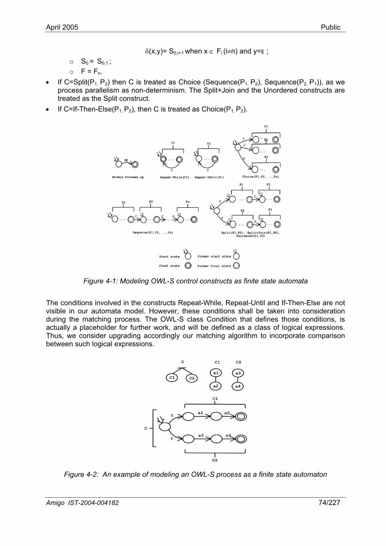
April 2005 Public
δ(x,y)= S0,i+1 when x ∈ Fi (i≠n) and y=ε ; o S0 = S0,1 ; o F = Fn.
• If C=Split(P1, P2) then C is treated as Choice (Sequence(P1, P2), Sequence(P2, P1)), as we process parallelism as non-determinism. The Split+Join and the Unordered constructs are treated as the Split construct.
• If C=If-Then-Else(P1, P2), then C is treated as Choice(P1, P2).
Figure 4-1: Modeling OWL-S control constructs as finite state automata
The conditions involved in the constructs Repeat-While, Repeat-Until and If-Then-Else are not visible in our automata model. However, these conditions shall be taken into consideration during the matching process. The OWL-S class Condition that defines those conditions, is actually a placeholder for further work, and will be defined as a class of logical expressions. Thus, we consider upgrading accordingly our matching algorithm to incorporate comparison between such logical expressions.
Figure 4-2: An example of modeling an OWL-S process as a finite state automaton
Amigo IST-2004-004182 74/227
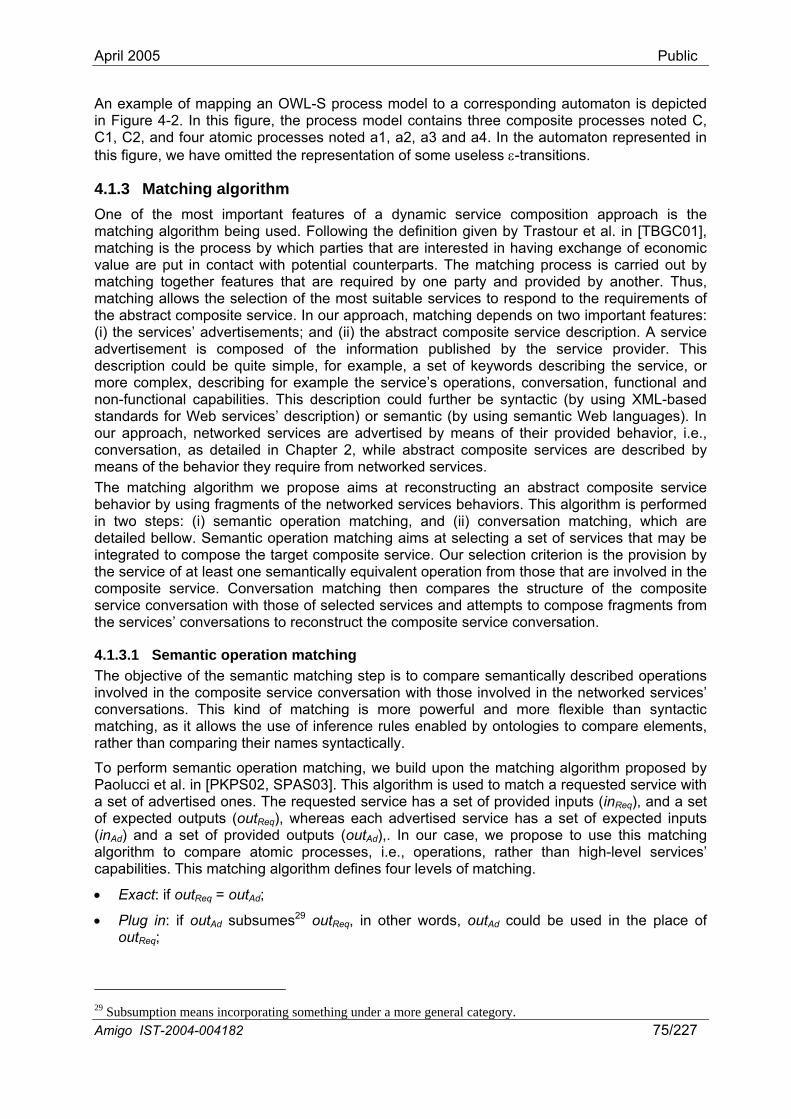
April 2005 Public
An example of mapping an OWL-S process model to a corresponding automaton is depicted in Figure 4-2. In this figure, the process model contains three composite processes noted C, C1, C2, and four atomic processes noted a1, a2, a3 and a4. In the automaton represented in this figure, we have omitted the representation of some useless ε-transitions.
4.1.3 Matching algorithm One of the most important features of a dynamic service composition approach is the matching algorithm being used. Following the definition given by Trastour et al. in [TBGC01], matching is the process by which parties that are interested in having exchange of economic value are put in contact with potential counterparts. The matching process is carried out by matching together features that are required by one party and provided by another. Thus, matching allows the selection of the most suitable services to respond to the requirements of the abstract composite service. In our approach, matching depends on two important features: (i) the services’ advertisements; and (ii) the abstract composite service description. A service advertisement is composed of the information published by the service provider. This description could be quite simple, for example, a set of keywords describing the service, or more complex, describing for example the service’s operations, conversation, functional and non-functional capabilities. This description could further be syntactic (by using XML-based standards for Web services’ description) or semantic (by using semantic Web languages). In our approach, networked services are advertised by means of their provided behavior, i.e., conversation, as detailed in Chapter 2, while abstract composite services are described by means of the behavior they require from networked services. The matching algorithm we propose aims at reconstructing an abstract composite service behavior by using fragments of the networked services behaviors. This algorithm is performed in two steps: (i) semantic operation matching, and (ii) conversation matching, which are detailed bellow. Semantic operation matching aims at selecting a set of services that may be integrated to compose the target composite service. Our selection criterion is the provision by the service of at least one semantically equivalent operation from those that are involved in the composite service. Conversation matching then compares the structure of the composite service conversation with those of selected services and attempts to compose fragments from the services’ conversations to reconstruct the composite service conversation.
4.1.3.1 Semantic operation matching The objective of the semantic matching step is to compare semantically described operations involved in the composite service conversation with those involved in the networked services’ conversations. This kind of matching is more powerful and more flexible than syntactic matching, as it allows the use of inference rules enabled by ontologies to compare elements, rather than comparing their names syntactically.
To perform semantic operation matching, we build upon the matching algorithm proposed by Paolucci et al. in [PKPS02, SPAS03]. This algorithm is used to match a requested service with a set of advertised ones. The requested service has a set of provided inputs (inReq), and a set of expected outputs (outReq), whereas each advertised service has a set of expected inputs (inAd) and a set of provided outputs (outAd),. In our case, we propose to use this matching algorithm to compare atomic processes, i.e., operations, rather than high-level services’ capabilities. This matching algorithm defines four levels of matching.
• Exact: if outReq = outAd;
• Plug in: if outAd subsumes29 outReq, in other words, outAd could be used in the place of outReq;
Amigo IST-2004-004182 75/227
29 Subsumption means incorporating something under a more general category.
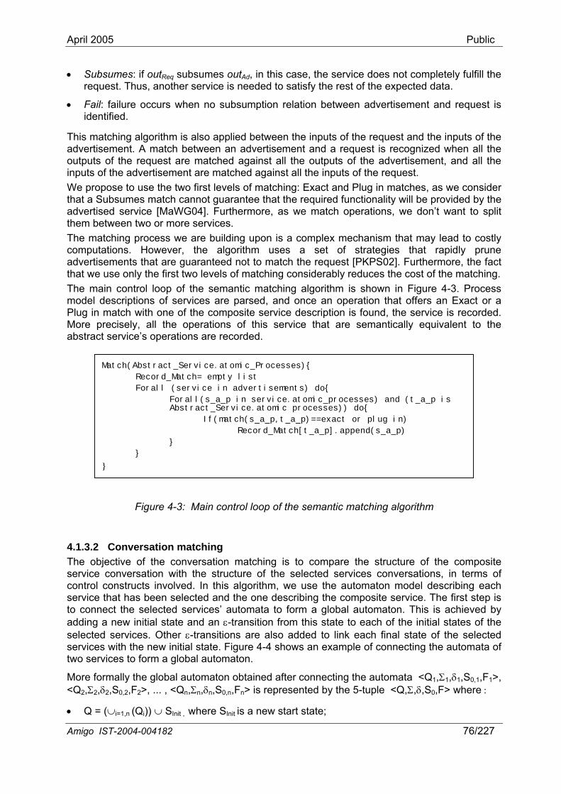
April 2005 Public
• Subsumes: if outReq subsumes outAd, in this case, the service does not completely fulfill the request. Thus, another service is needed to satisfy the rest of the expected data.
• Fail: failure occurs when no subsumption relation between advertisement and request is identified.
This matching algorithm is also applied between the inputs of the request and the inputs of the advertisement. A match between an advertisement and a request is recognized when all the outputs of the request are matched against all the outputs of the advertisement, and all the inputs of the advertisement are matched against all the inputs of the request. We propose to use the two first levels of matching: Exact and Plug in matches, as we consider that a Subsumes match cannot guarantee that the required functionality will be provided by the advertised service [MaWG04]. Furthermore, as we match operations, we don’t want to split them between two or more services. The matching process we are building upon is a complex mechanism that may lead to costly computations. However, the algorithm uses a set of strategies that rapidly prune advertisements that are guaranteed not to match the request [PKPS02]. Furthermore, the fact that we use only the first two levels of matching considerably reduces the cost of the matching. The main control loop of the semantic matching algorithm is shown in Figure 4-3. Process model descriptions of services are parsed, and once an operation that offers an Exact or a Plug in match with one of the composite service description is found, the service is recorded. More precisely, all the operations of this service that are semantically equivalent to the abstract service’s operations are recorded.
Match(Abstract_Service.atomic_Processes){
Record_Match= empty list
Forall (service in advertisements) do{
Forall(s_a_p in service.atomic_processes) and (t_a_p is Abstract_Service.atomic processes)) do{
If(match(s_a_p,t_a_p)==exact or plug in)
Record_Match[t_a_p].append(s_a_p)
}
}
}
Figure 4-3: Main control loop of the semantic matching algorithm
4.1.3.2 Conversation matching The objective of the conversation matching is to compare the structure of the composite service conversation with the structure of the selected services conversations, in terms of control constructs involved. In this algorithm, we use the automaton model describing each service that has been selected and the one describing the composite service. The first step is to connect the selected services’ automata to form a global automaton. This is achieved by adding a new initial state and an ε-transition from this state to each of the initial states of the selected services. Other ε-transitions are also added to link each final state of the selected services with the new initial state. Figure 4-4 shows an example of connecting the automata of two services to form a global automaton.
More formally the global automaton obtained after connecting the automata <Q1,Σ1,δ1,S0,1,F1>, <Q2,Σ2,δ2,S0,2,F2>, ... , <Qn,Σn,δn,S0,n,Fn> is represented by the 5-tuple <Q,Σ,δ,S0,F> where :
• Q = (∪i=1,n (Qi)) ∪ SInit , where SInit is a new start state;
Amigo IST-2004-004182 76/227
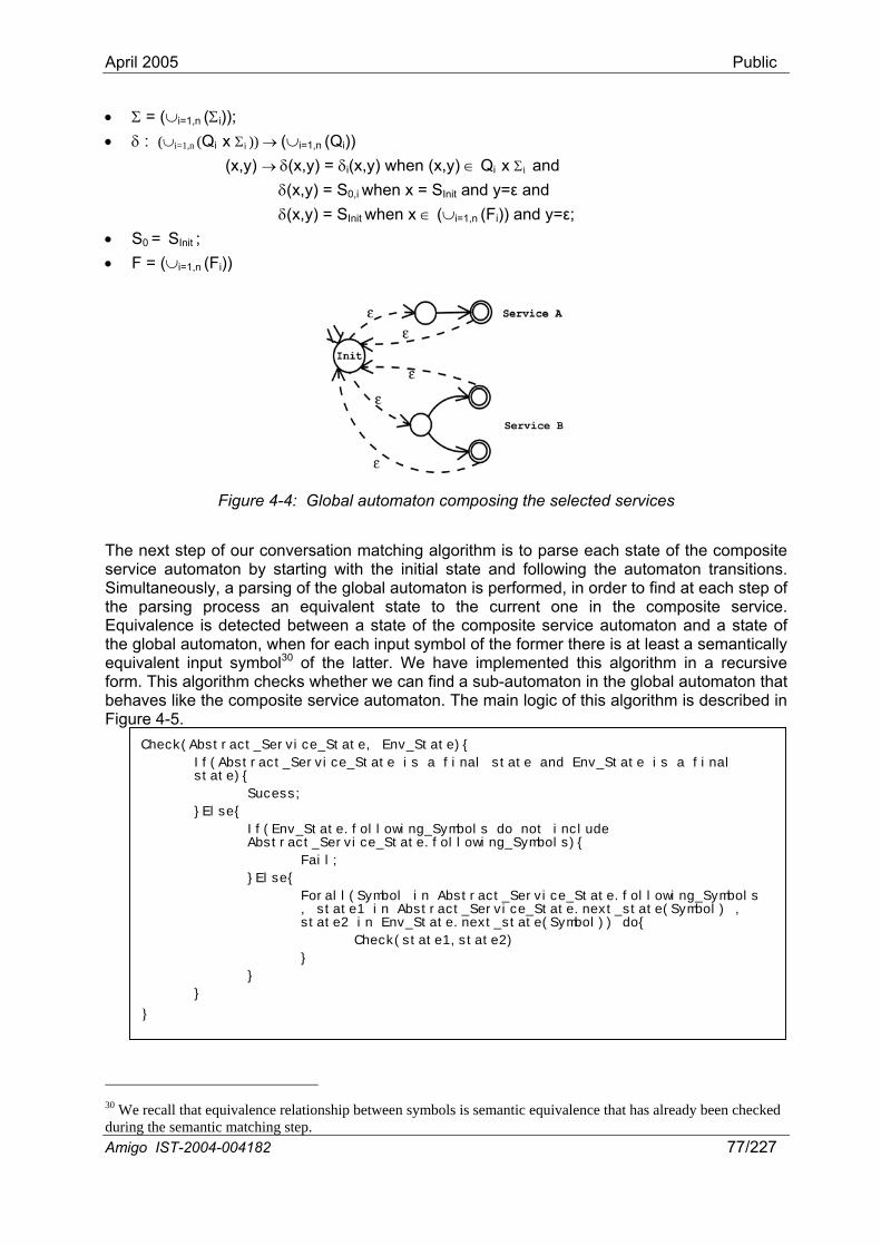
April 2005 Public
• Σ = (∪i=1,n (Σi)); • δ : (∪i=1,n (Qi x Σi )) → (∪i=1,n (Qi))
(x,y) → δ(x,y) = δi(x,y) when (x,y) ∈ Qi x Σi and δ(x,y) = S0,i when x = SInit and y=ε and δ(x,y) = SInit when x ∈ (∪i=1,n (Fi)) and y=ε;
• S0 = SInit ; • F = (∪i=1,n (Fi))
Figure 4-4: Global automaton composing the selected services
The next step of our conversation matching algorithm is to parse each state of the composite service automaton by starting with the initial state and following the automaton transitions. Simultaneously, a parsing of the global automaton is performed, in order to find at each step of the parsing process an equivalent state to the current one in the composite service. Equivalence is detected between a state of the composite service automaton and a state of the global automaton, when for each input symbol of the former there is at least a semantically equivalent input symbol30 of the latter. We have implemented this algorithm in a recursive form. This algorithm checks whether we can find a sub-automaton in the global automaton that behaves like the composite service automaton. The main logic of this algorithm is described in Figure 4-5.
Check(Abstract_Service_State, Env_State){
If(Abstract_Service_State is a final state and Env_State is a final state){
Sucess;
}Else{
If(Env_State.following_Symbols do not include Abstract_Service_State.following_Symbols){
Fail;
}Else{
Forall(Symbol in Abstract_Service_State.following_Symbols , state1 in Abstract_Service_State.next_state(Symbol) , state2 in Env_State.next_state(Symbol)) do{
Check(state1,state2)
}
}
}
}
Amigo IST-2004-004182 77/227
30 We recall that equivalence relationship between symbols is semantic equivalence that has already been checked during the semantic matching step.
April 2005 Public
Figure 4-5: Main logic of the conversation matching algorithm
This algorithm gives a list of sub-automata of the global automaton that behave like the composite service automaton. Once this list is produced, a last step consists in checking whether the atomic conversation constraints, have been respected in each sub-automaton. As the global automaton is modeled as a union of the selected services automata, it is easy to check whether an atomic conversation fragment, that is, a set of transitions, is provided by a single service. Indeed, it is sufficient to verify that for each transition set that corresponds to an atomic conversation there is no ε-transition going to the initial state before this conversation is finished (ε-transitions that connect final states to the initial state of the global automaton mark the end of a service conversation and the passing to a new one). After rejecting those sub-automata that don’t verify the atomic conversation constraints, we arbitrarily select one of the remainders, as they all behave as the target composite service. However it is possible to introduce some selection criteria and to choose one composition scheme rather than another. For example, we can state that a composition is more complex, costly, failure-prone to manage when it integrates a large number of services, leading to select the composition that involves the fewest services. Another example is the QoS offered by a composition. For example, if we can evaluate the QoS parameters of a composition using the QoS parameters of the involved services, it will be possible to choose composition schemes that are closer to the user’s requirements (QoS-aware composition). We can also apply a selection criterion concerning the middeware platforms of the involved services. In this case, it is possible to choose a composition scheme that involves services from the same platform, in order to avoid the use of middleware-layer interoperability methods that will increase the total response time. Using the sub-automaton that has been selected, an executable description of the composite service that includes references to existing environment’s services is generated, and may be passed to an OWL-S process model execution engine (e.g., the one introduced in [PASS03]), which can execute this description by invoking the appropriate service operations. Conversation integration is a difficult task that may lead in some cases to costly computations. Such cases could be: when the depth of the composite service automaton is very large, resulting in a high cost due to the automaton parsing; or, when there is a large number of selected services that offer similar conversations, leading to explore a large number of paths at the same time. A number of optimizations may be applied to the conversation matching algorithm in order to reduce the computation cost. Such an optimization is the reduction of the size of the global automaton, by comparing the conversations offered by services during the service selection process and rejecting services that offer similar conversations to the already selected ones. Another kind of optimization is to reduce the number of paths being explored simultaneously, by exploring only n1 paths at the same time, rather than exploring all the n available paths at the same time (where n1<n). Thus, if one of the n1 selected paths is successful, we keep this path and stop the algorithm, otherwise, n1 other paths are explored. The number of selected services may also be reduced during the service selection step by taking into account some contextual and/or QoS information.
4.1.3.3 Example In this section we show a simple example of how our matching algorithm could be used to match conversations. This example is inspired from one of the Amigo scenarios. "...Robert, (Maria's and Jerry's son) is waiting for his best friend to play video games. Robert's friend arrives bringing his new portable DVD player. He proposes to watch a film rather than playing games, and asks Robert if he has any new films in his home digital resource database. In order to use his friend's DVD player, Robert has asked the system to consider this device as a guest device and to authorize it to use the home services. This player is quite complex as it takes into consideration some user's contextual and access rights information. The former is
Amigo IST-2004-004182 78/227
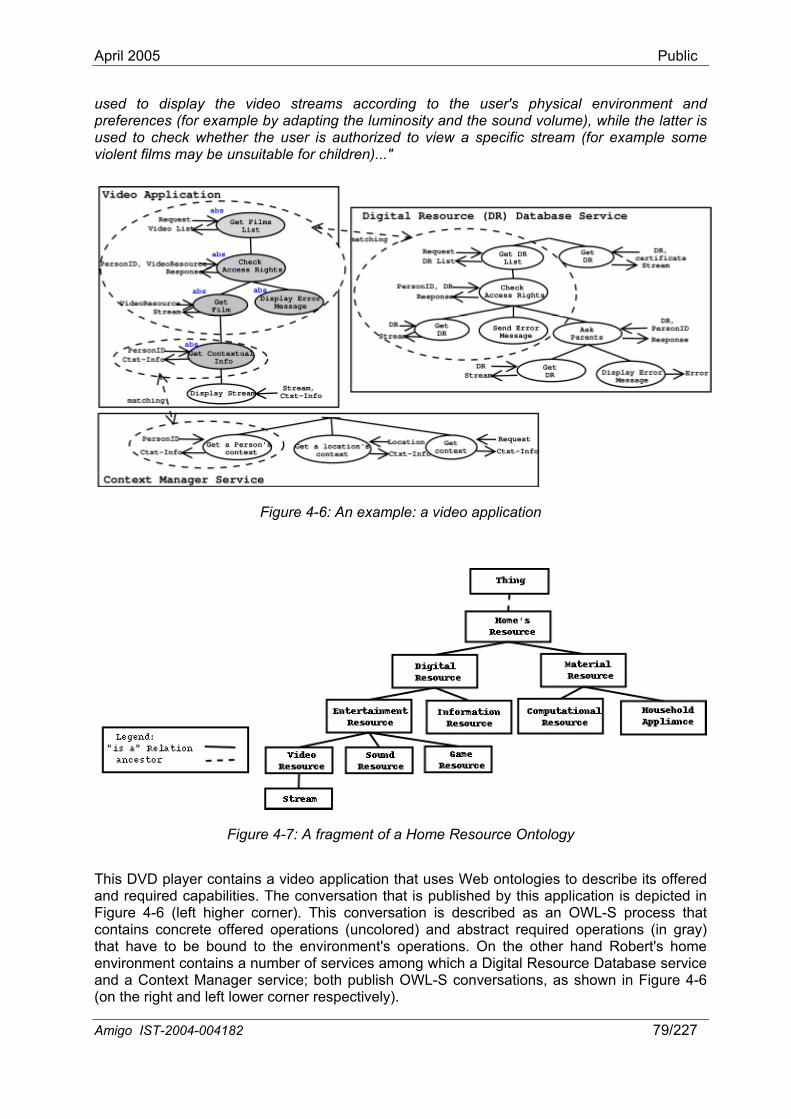
April 2005 Public
used to display the video streams according to the user's physical environment and preferences (for example by adapting the luminosity and the sound volume), while the latter is used to check whether the user is authorized to view a specific stream (for example some violent films may be unsuitable for children)..."
Figure 4-6: An example: a video application
Figure 4-7: A fragment of a Home Resource Ontology
This DVD player contains a video application that uses Web ontologies to describe its offered and required capabilities. The conversation that is published by this application is depicted in Figure 4-6 (left higher corner). This conversation is described as an OWL-S process that contains concrete offered operations (uncolored) and abstract required operations (in gray) that have to be bound to the environment's operations. On the other hand Robert's home environment contains a number of services among which a Digital Resource Database service and a Context Manager service; both publish OWL-S conversations, as shown in Figure 4-6 (on the right and left lower corner respectively).
Amigo IST-2004-004182 79/227
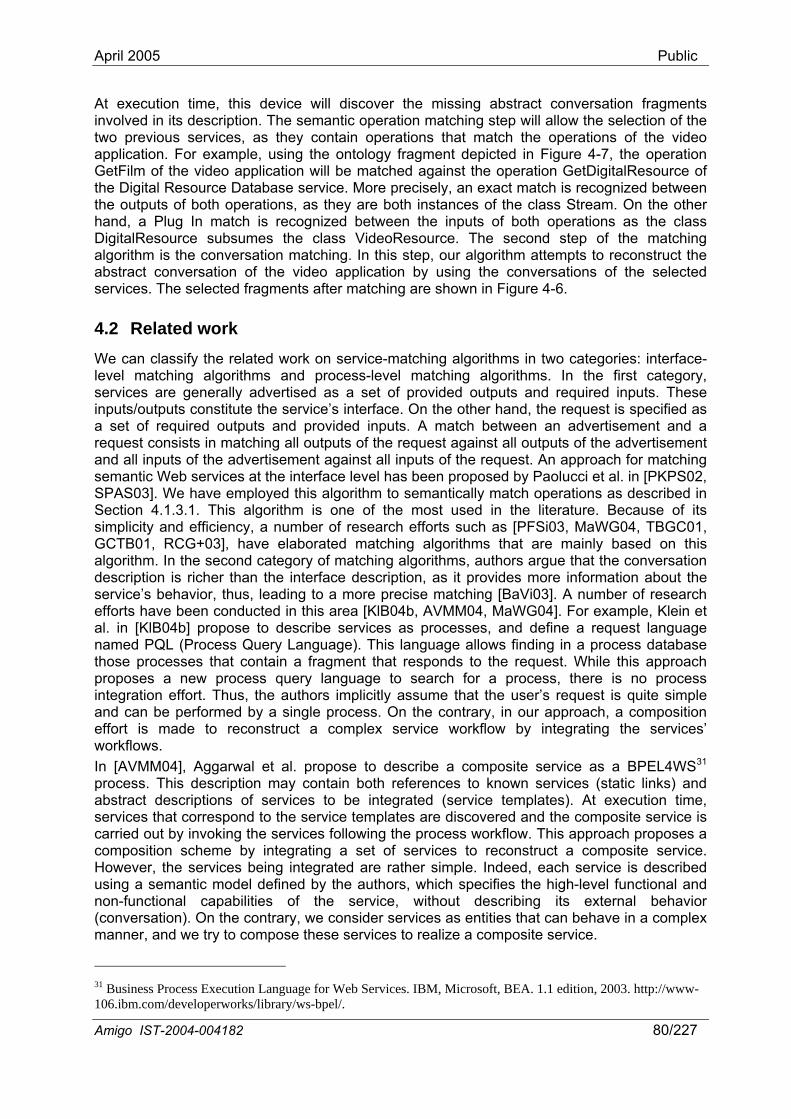
April 2005 Public
At execution time, this device will discover the missing abstract conversation fragments involved in its description. The semantic operation matching step will allow the selection of the two previous services, as they contain operations that match the operations of the video application. For example, using the ontology fragment depicted in Figure 4-7, the operation GetFilm of the video application will be matched against the operation GetDigitalResource of the Digital Resource Database service. More precisely, an exact match is recognized between the outputs of both operations, as they are both instances of the class Stream. On the other hand, a Plug In match is recognized between the inputs of both operations as the class DigitalResource subsumes the class VideoResource. The second step of the matching algorithm is the conversation matching. In this step, our algorithm attempts to reconstruct the abstract conversation of the video application by using the conversations of the selected services. The selected fragments after matching are shown in Figure 4-6.
4.2 Related work We can classify the related work on service-matching algorithms in two categories: interface-level matching algorithms and process-level matching algorithms. In the first category, services are generally advertised as a set of provided outputs and required inputs. These inputs/outputs constitute the service’s interface. On the other hand, the request is specified as a set of required outputs and provided inputs. A match between an advertisement and a request consists in matching all outputs of the request against all outputs of the advertisement and all inputs of the advertisement against all inputs of the request. An approach for matching semantic Web services at the interface level has been proposed by Paolucci et al. in [PKPS02, SPAS03]. We have employed this algorithm to semantically match operations as described in Section 4.1.3.1. This algorithm is one of the most used in the literature. Because of its simplicity and efficiency, a number of research efforts such as [PFSi03, MaWG04, TBGC01, GCTB01, RCG+03], have elaborated matching algorithms that are mainly based on this algorithm. In the second category of matching algorithms, authors argue that the conversation description is richer than the interface description, as it provides more information about the service’s behavior, thus, leading to a more precise matching [BaVi03]. A number of research efforts have been conducted in this area [KlB04b, AVMM04, MaWG04]. For example, Klein et al. in [KlB04b] propose to describe services as processes, and define a request language named PQL (Process Query Language). This language allows finding in a process database those processes that contain a fragment that responds to the request. While this approach proposes a new process query language to search for a process, there is no process integration effort. Thus, the authors implicitly assume that the user’s request is quite simple and can be performed by a single process. On the contrary, in our approach, a composition effort is made to reconstruct a complex service workflow by integrating the services’ workflows. In [AVMM04], Aggarwal et al. propose to describe a composite service as a BPEL4WS31 process. This description may contain both references to known services (static links) and abstract descriptions of services to be integrated (service templates). At execution time, services that correspond to the service templates are discovered and the composite service is carried out by invoking the services following the process workflow. This approach proposes a composition scheme by integrating a set of services to reconstruct a composite service. However, the services being integrated are rather simple. Indeed, each service is described using a semantic model defined by the authors, which specifies the high-level functional and non-functional capabilities of the service, without describing its external behavior (conversation). On the contrary, we consider services as entities that can behave in a complex manner, and we try to compose these services to realize a composite service.
31 Business Process Execution Language for Web Services. IBM, Microsoft, BEA. 1.1 edition, 2003. http://www-106.ibm.com/developerworks/library/ws-bpel/.
Amigo IST-2004-004182 80/227
April 2005 Public
Another process-level matching algorithm is proposed by Majithia et al. in [MaWG04]. In this approach, the user’s request is specified in a high-level manner and automatically mapped to an abstract workflow. Then, service instances that match the ones described in the abstract workflow, in terms on inputs outputs pre-conditions and effects, are discovered in the network, and a concrete workflow description is constituted. As we have noticed in the previous approach, the service composition scheme that is proposed in this approach does not involve any process integration, as the Web services are only described at the interface level.
4.3 Discussion In the diverse, dynamic Amigo environment, dynamic composition of multiple services will enable advanced service provision in numerous ways, combining services from all four Amigo application domains. Our objective is to allow composite services that are abstractly described, to be executed in the Amigo environment, by integrating on the fly the available environment’s services. A key feature of Amigo services is their heterogeneity. Most existing composition approaches poorly deal with heterogeneity, since they assume that services being integrated have been developed to conform syntactically in terms of interfaces and conversations. Refining the generic principles established in Chapter 2, we elaborate a concrete conformance relation and associated interoperability method enabling the dynamic composition of multiple services. Our solution offers flexibility, by enabling semantic matching of interfaces, and ad hoc reconstruction of an abstract composition workflow from the conversations of available environment’s services. We employ the Semantic Web Services paradigm; however, our approach is more general and could use another similar paradigm. Our solution is achieved in two steps. In the first step, we perform semantic matching of interfaces, which leads to the selection of a set of services that are candidate for integration. In the second step, we perform conversation matching on the set of the previously selected services, thus obtaining a conversation composition that behaves as the target composite service. Our matching is based on a mapping of OWL-S conversations to finite state automata. This mapping facilitates the conversation integration process, as it transforms this problem to an automaton equivalence issue.
As already stated, the elaborated approach to conversation integration can be costly in terms of computation. We have indicated several optimizations aiming at reducing its cost. We aim at integrating these optimizations into our approach and evaluating it for performance. Further, the involved semantic matching and the execution of the composed service entail the employment of OWL reasoning tools and OWL-S execution tools, which introduce additional runtime overhead. As a whole, service composition within Amigo shall be executed online, most probably on resource-constrained devices. Thus, as indicated in Chapter 2, we shall investigate within Amigo base online tools and techniques to support ad hoc service composition with acceptable runtime cost on wireless, resource-constrained devices. This will make part of our further work on the elaboration of service composition within Amigo, which will specifically be addressed in Task 3.6 on adaptive service composition of Work package WP3.
Amigo IST-2004-004182 81/227

April 2005 Public
5 Middleware-layer interoperability methods Middleware holds a predominant role in the service-oriented architecture for the networked home environment. Communication relationships amongst application components involve the use of protocols, making application-related services tightly coupled to middleware. Additionally, to overcome resource constraints like network-related limited bandwidth, and support the various relevant applications, several communication models have arisen. Thus, as there exist many styles of communication and consequently many styles of middleware, we have to deal with middleware heterogeneity [GBS03a]. Significantly, a service implemented upon a specific middleware cannot interoperate with services developed upon another. Similarly, we cannot predict at design time the execution environment of services deployed in the networked home, in particular due to the network’s openness. However, no matter which underlying communication protocols are present, services deployed on the various devices of the networked home environment must both discover and interact with the services available in their vicinity. More precisely, service discovery protocols enable finding and using networked services without any previous knowledge of their specific location (see Chapter 3). And, with the advent of both mobility and wireless networking, SDPs are taking on a major role in networked environments, and are the source of a major heterogeneity issue across middleware. Furthermore, once services are discovered, applications need to use the same interaction protocol to allow unanticipated connections and interactions with them. Consequently, a second heterogeneity issue appears among middleware. Summarizing, middleware for the networked home environment must overcome two heterogeneity issues to provide interoperability, i.e.:
- Heterogeneity of service discovery protocols, and
- Heterogeneity of interaction protocols between services.
In addition, both SDPs and interaction protocols are not protected from evolution across time (versioning). Indeed, an application may neither interact correctly nor be compatible with services if they use different versions of the same protocol [RyWo04]. Protocol evolution increases communication failure probability between two mobile devices.
As outlined above, interoperability among entities of the networked home environment, which in particular integrates mobile devices that randomly join the networked home for possibly short periods of time, is becoming a real issue to overcome. Networked devices must be aware of their dynamic environment that evolves over time, and further adapt their communication paradigms according to the environment. Thus, distributed systems for the networked home environment must provide efficient mechanisms to detect and interpret protocols currently used, which are not known in advance. Furthermore, detection and interpretation must be achieved without increasing consumption of resources on the resource-constrained devices. As presented in Chapter 2, the ability of networked services to compose relates to the definition of adequate conformance relations and related interoperability methods, based on customizers, at the connector level. This chapter then introduces base, concrete mechanisms for achieving interoperability among services based on heterogeneous middleware platforms, hence elaborating specific conformance relations and interoperability methods at middleware level for the Amigo system. Compared to Chapter 2, herein, we elaborate focused, optimized modeling of SDP and interaction protocol middleware, which enables direct conformance checking within these two well-defined classes of connectors. We reuse concepts from software architecture enriched with event-based parsing techniques to drastically improve middleware interoperability, enabling applications to be efficiently aware of their environment. The originality of our approach comes from the trade-offs achieved among efficiency, interoperability and flexibility. Our solution may further be applied to any existing middleware platform.
Amigo IST-2004-004182 83/227
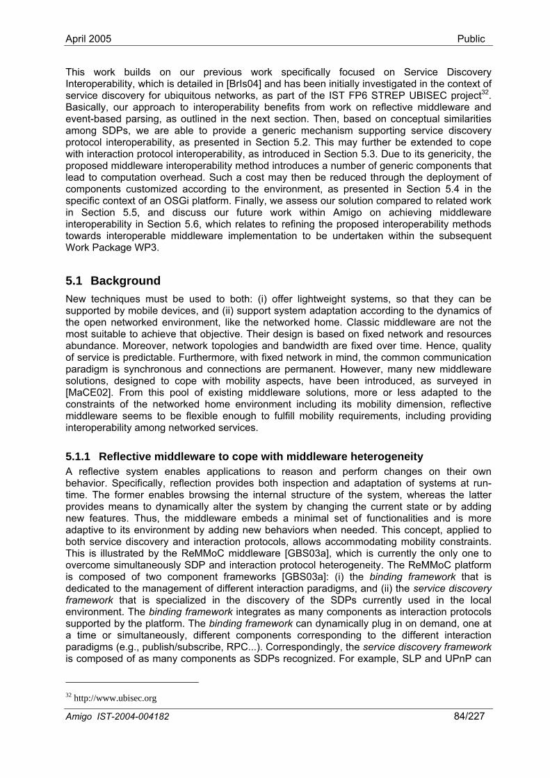
April 2005 Public
This work builds on our previous work specifically focused on Service Discovery Interoperability, which is detailed in [BrIs04] and has been initially investigated in the context of service discovery for ubiquitous networks, as part of the IST FP6 STREP UBISEC project32. Basically, our approach to interoperability benefits from work on reflective middleware and event-based parsing, as outlined in the next section. Then, based on conceptual similarities among SDPs, we are able to provide a generic mechanism supporting service discovery protocol interoperability, as presented in Section 5.2. This may further be extended to cope with interaction protocol interoperability, as introduced in Section 5.3. Due to its genericity, the proposed middleware interoperability method introduces a number of generic components that lead to computation overhead. Such a cost may then be reduced through the deployment of components customized according to the environment, as presented in Section 5.4 in the specific context of an OSGi platform. Finally, we assess our solution compared to related work in Section 5.5, and discuss our future work within Amigo on achieving middleware interoperability in Section 5.6, which relates to refining the proposed interoperability methods towards interoperable middleware implementation to be undertaken within the subsequent Work Package WP3.
5.1 Background New techniques must be used to both: (i) offer lightweight systems, so that they can be supported by mobile devices, and (ii) support system adaptation according to the dynamics of the open networked environment, like the networked home. Classic middleware are not the most suitable to achieve that objective. Their design is based on fixed network and resources abundance. Moreover, network topologies and bandwidth are fixed over time. Hence, quality of service is predictable. Furthermore, with fixed network in mind, the common communication paradigm is synchronous and connections are permanent. However, many new middleware solutions, designed to cope with mobility aspects, have been introduced, as surveyed in [MaCE02]. From this pool of existing middleware solutions, more or less adapted to the constraints of the networked home environment including its mobility dimension, reflective middleware seems to be flexible enough to fulfill mobility requirements, including providing interoperability among networked services.
5.1.1 Reflective middleware to cope with middleware heterogeneity A reflective system enables applications to reason and perform changes on their own behavior. Specifically, reflection provides both inspection and adaptation of systems at run-time. The former enables browsing the internal structure of the system, whereas the latter provides means to dynamically alter the system by changing the current state or by adding new features. Thus, the middleware embeds a minimal set of functionalities and is more adaptive to its environment by adding new behaviors when needed. This concept, applied to both service discovery and interaction protocols, allows accommodating mobility constraints. This is illustrated by the ReMMoC middleware [GBS03a], which is currently the only one to overcome simultaneously SDP and interaction protocol heterogeneity. The ReMMoC platform is composed of two component frameworks [GBS03a]: (i) the binding framework that is dedicated to the management of different interaction paradigms, and (ii) the service discovery framework that is specialized in the discovery of the SDPs currently used in the local environment. The binding framework integrates as many components as interaction protocols supported by the platform. The binding framework can dynamically plug in on demand, one at a time or simultaneously, different components corresponding to the different interaction paradigms (e.g., publish/subscribe, RPC...). Correspondingly, the service discovery framework is composed of as many components as SDPs recognized. For example, SLP and UPnP can
32 http://www.ubisec.org
Amigo IST-2004-004182 84/227
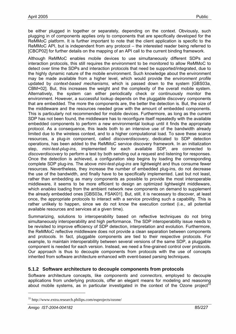
April 2005 Public
be either plugged in together or separately, depending on the context. Obviously, such plugging in of components applies only to components that are specifically developed for the ReMMoC platform. It is further important to note that the client application is specific to the ReMMoC API, but is independent from any protocol – the interested reader being referred to [CBCP02] for further details on the mapping of an API call to the current binding framework.
Although ReMMoC enables mobile devices to use simultaneously different SDPs and interaction protocols, this still requires the environment to be monitored to allow ReMMoC to detect over time the SDPs and interaction protocols that need be supported/integrated, due to the highly dynamic nature of the mobile environment. Such knowledge about the environment may be made available from a higher level, which would provide the environment profile updated by context-based mechanisms, which is passed down to the system [GBS03a, CBM+02]. But, this increases the weight and the complexity of the overall mobile system. Alternatively, the system can either periodically check or continuously monitor the environment. However, a successful lookup depends on the pluggable discovery components that are embedded. The more the components are, the better the detection is. But, the size of the middleware and the resources needed grow with the amount of embedded components. This is particularly not recommended for mobile devices. Furthermore, as long as the current SDP has not been found, the middleware has to reconfigure itself repeatedly with the available embedded components to perform a new environmental lookup until it finds the appropriate protocol. As a consequence, this leads both to an intensive use of the bandwidth already limited due to the wireless context, and to a higher computational load. To save these scarce resources, a plug-in component, called discoverdiscovery, dedicated to SDP detection operations, has been added to the ReMMoC service discovery framework. In an initialization step, mini-test-plug-ins, implemented for each available SDP, are connected to discoverdiscovery to perform a test by both sending out a request and listening for responses. Once the detection is achieved, a configuration step begins by loading the corresponding complete SDP plug-ins. The above mini-test-plug-ins are lightweight and thus consume fewer resources. Nevertheless, they increase the number of embedded plug-ins, do not decrease the use of the bandwidth, and finally have to be specifically implemented. Last but not least, rather than embedding as many components as possible to provide the most interoperable middleware, it seems to be more efficient to design an optimized lightweight middleware, which enables loading from the ambient network new components on demand to supplement the already embedded ones [GBS03a, FSAK01]. But, still, it is necessary to discover, at least once, the appropriate protocols to interact with a service providing such a capability. This is rather unlikely to happen, since we do not know the execution context (i.e., all potential available resources and services at a given time).
Summarizing, solutions to interoperability based on reflective techniques do not bring simultaneously interoperability and high performance. The SDP interoperability issue needs to be revisited to improve efficiency of SDP detection, interpretation and evolution. Furthermore, the ReMMoC reflective middleware does not provide a clean separation between components and protocols. In fact, pluggable components are tied to their respective protocols. For example, to maintain interoperability between several versions of the same SDP, a pluggable component is needed for each version. Instead, we need a fine-grained control over protocols. Our approach is thus to decouple components from protocols with the use of concepts inherited from software architecture enhanced with event-based parsing techniques.
5.1.2 Software architecture to decouple components from protocols Software architecture concepts, like components and connectors, employed to decouple applications from underlying protocols, offer an elegant means for modeling and reasoning about mobile systems, as in particular investigated in the context of the Ozone project33 33 http://www.extra.research.philips.com/euprojects/ozone/
Amigo IST-2004-004182 85/227
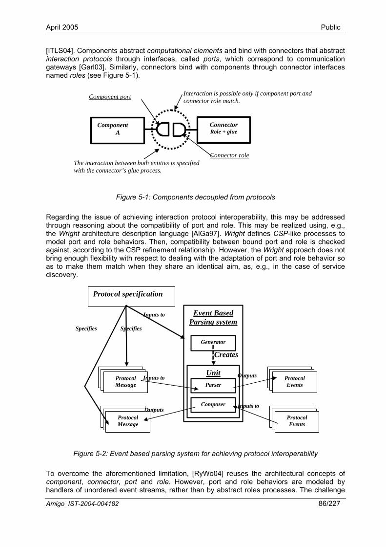
April 2005 Public
[ITLS04]. Components abstract computational elements and bind with connectors that abstract interaction protocols through interfaces, called ports, which correspond to communication gateways [Garl03]. Similarly, connectors bind with components through connector interfaces named roles (see Figure 5-1).
Amigo IST-2004-004182 86/227
Component A
Connector role
Component port Intera tion is possible only if component port and connector role match.
c
Connector
The interaction between both entities is specified with the connector’s glue process.
Role + glue
Figure 5-1: Components decoupled from protocols
Regarding the issue of achieving interaction protocol interoperability, this may be addressed through reasoning about the compatibility of port and role. This may be realized using, e.g., the Wright architecture description language [AlGa97]. Wright defines CSP-like processes to model port and role behaviors. Then, compatibility between bound port and role is checked against, according to the CSP refinement relationship. However, the Wright approach does not bring enough flexibility with respect to dealing with the adaptation of port and role behavior so as to make them match when they share an identical aim, as, e.g., in the case of service discovery.
Event Based Parsing system
Unit Parser
Generator
Creates
Protocol
Composer
Message
Protocol Message
Inputs to Outputs
Inputs to Outputs
Protocol specification
Specifies Specifies
Inputs to
Protocol Events
Protocol Events
Figure 5-2: Event based parsing system for achieving protocol interoperability
To overcome the aforementioned limitation, [RyWo04] reuses the architectural concepts of component, connector, port and role. However, port and role behaviors are modeled by handlers of unordered event streams, rather than by abstract roles processes. The challenge
April 2005 Public
is then to transform protocol messages into events, and interpret them according to a protocol specification. To achieve this, an event-based parsing system, composed of generator, composer, unit, parser and proxy, is used (see Figure 5-2). A protocol specification feeds a generator that generates a dedicated parser and composer. The former takes, as input, protocol messages that are decomposed as tokens, and outputs the corresponding events. The latter does the inverse process: it takes series of events and transforms them into protocol messages. Parser and composer form a unit, which is specific to one protocol. Generators are able to generate on the fly new units, as needed, for different specifications. As a result, whatever the underlying protocol is, messages from a component are always transformed into
l interoperability is maintained.
Summarizing, event-based parsing is interesting in theory for its flexibility, and opens new perspectives to overcome protocol heterogeneity. However, it is still confined to theory: it has been applied only to th rotocol interoperability between two similar protocols that differ with only small changes. Therefore, [RyWo04] addresses heterogeneity issues neither for SDPs nor for interaction protocols, but brings
event-based parsing applied to eroperability in the open network
events through the adequate parser, and conversely, events sent towards a component are always transformed into protocol messages understood by this component through its adequate composer. Furthermore, events are sent from one component to another through a proxy, whose role is to forward handled events to the composer of the remote component (see Figure 5-3). The latter can either discard some events if they are unknown or force the generator to produce a new unit more suitable to parsed events. Thus, any connector gets represented as a universal event communication bus, which is able to transport any event, independently of any protocol, as the protocol reconstruction process is left to each extremity. Thereby, event streams are hidden from components and thus protoco
e protocol evolution issue, as it is simpler to test p
interesting concepts. In the next section, we show how software architecture enables efficient SDP detection and intenvironment in general and the networked home environment in particular.
Amigo IST-2004-004182 87/227
Proxy
Event Handler
Component A
Event-Based Parsing system
Unit Parser
Composer
Generator
Event-Based Parsing system
Unit Parser
Composer
Generator
Creates Component
B
Creates
Figure 5-3: Interaction between two components
5.2 Service discovery protocol interoperability With the emergence of mobility and wireless technologies, SDP heterogeneity becomes a major issue. Our objective is to provide a solution to SDP interoperability, which both induces low resource consumption and introduces a lightweight mechanism that may be adapted easily to any platform and allow for integrating third-party services that cannot be changed,
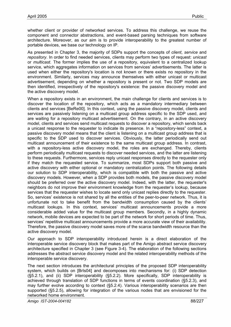
April 2005 Public
whether client or provider of networked services. To address this challenge, we reuse the component and connector abstractions, and event-based parsing techniques from software architecture. Moreover, as our aim is to provide interoperability to the greatest number of portable devices, we base our technology on IP.
As presented in Chapter 3, the majority of SDPs support the concepts of client, service and repository. In order to find needed services, clients may perform two types of request: unicast or multicast. The former implies the use of a repository, equivalent to a centralized lookup service, which aggregates information on services from services’ advertisements. The latter is used when either the repository's location is not known or there exists no repository in the environment. Similarly, services may announce themselves with either unicast or multicast advertisement, depending on whether a repository is present or not. Two SDP models are then identified, irrespectively of the repository's existence: the passive discovery model and the active discovery model.
When a repository exists in an environment, the main challenge for clients and services is to discover the location of the repository, which acts as a mandatory intermediary between clients and services [BeRe00]. In this context, using the passive discovery model, clients and services are passively li
Amigo IST-2004-004182 88/227
stening on a multicast group address specific to the SDP used, and
existence to the same multicast group address. In contrast,
en a SDP provides both models, the passive discovery model should be preferred over the active discovery model. Indeed, with the latter, the requester's
their environment knowledge from the requester’s lookup, because
ilds on [BrIs04] and decomposes into mechanisms for: (i) SDP detection (§5 1achieved through translation of SDP functions in terms of may further evolve 4). Various interoperability scenarios are then sup r ous nodes that are envisioned for the networked home environment.
are waiting for a repository multicast advertisement. On the contrary, in an active discovery model, clients and services send multicast requests to discover a repository, which sends back a unicast response to the requester to indicate its presence. In a “repository-less” context, a passive discovery model means that the client is listening on a multicast group address that is specific to the SDP used to discover services. Obviously, the latter periodically send out multicast announcement of theirwith a repository-less active discovery model, the roles are exchanged. Thereby, clients perform periodically multicast requests to discover needed services, and the latter are listening to these requests. Furthermore, services reply unicast responses directly to the requester only if they match the requested service. To summarize, most SDPs support both passive and active discovery with either optional or mandatory centralization points. The following details our solution to SDP interoperability, which is compatible with both the passive and active discovery models. However, wh
neighbors do not improveservices that the requester wishes to locate send only unicast replies directly to the requester. So, services’ existence is not shared by all the entities of the peer-to-peer network. Thus, it is unfortunate not to take benefit from the bandwidth consumption caused by the clients’ multicast lookups. In this context, services’ multicast announcements provide a more considerable added value for the multicast group members. Secondly, in a highly dynamic network, mobile devices are expected to be part of the network for short periods of time. Thus, services’ repetitive multicast announcements provide a more accurate view of their availability. Therefore, the passive discovery model saves more of the scarce bandwidth resource than the active discovery model.
Our approach to SDP interoperability introduced herein is a direct elaboration of the interoperable service discovery block that makes part of the Amigo abstract service discovery architecture specified in Chapter 3 (see Figure 3-4). The elaboration of the following sections addresses the abstract service discovery model and the related interoperability methods of the interoperable service discovery.
The next section introduces the architectural principles of the proposed SDP interoperability system, which bu
.2. ), and (ii) SDP interoperability (§5.2.2). More specifically, SDP interoperability is events coordination (§5.2.3), and
according to context (§5.2.po ted (§5.2.5), allowing for integration of the vari
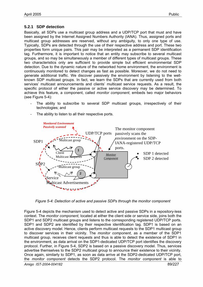
April 2005 Public
5.2.1 SDBasically, a group address and a UDP/TCP port that must and have been assigned by the Internet Assigned Numbers Authority (IANA). Thus, assigned ports and multicast group addresses are reserved, without any ambiguity, to only one type of use. Typically, SDPs are detected through the use of their respective address and port. These two properties form unique pairs. This pair may be interpreted as a permanent SDP identification tag. Furthermore, it is important to notice that an entity may subscribe to several multicast groups, and so may be simultaneously a member of different types of multicast groups. These two characteristics only are sufficient to provide simple but efficient environmental SDP detection. Due to the dynamic nature of the networked home environment, the environment is continuously monitored to detect changes as fast as possible. Moreover, we do not need to generate additional traffic. We discover passively the environment by listening to the well-known SDP multicast groups. In fact, we learn the SDPs that are currently used from both services’ multicast announcements and clients’ multicast service requests. As a result, the specific protocol of either the passive or active service discovery may be determined. To achieve this feature, a component, called monitor component, embeds two major behaviors (see Figure 5-4):
- their
P detection ll SDPs use a multicast
The ability to subscribe to several SDP multicast groups, irrespectively of technologies; and
- The ability to listen to all their respective ports.
Monitored Environment Passively scanned
Monitor Component
Multicast group
Multicast group
Service Multicast Advertisements
Client Multicast Requests
SDP1
SDP2
• SDP 1 detected • SDP 2 detected
The monitor component passively scans the environment on the SDP-IANA-registered UDP/TCP ports.
UDP/TCP ports
1
2
Figure 5-4: Detection of active and passive SDPs through the monitor component
Figure 5-4 depicts the mechanism used to detect active and passive SDPs in a repository-less context. The monitor component, located at either the client side or service side, joins both the SDP1 and SDP2 multicast groups and listens to the corresponding registered UDP/TCP ports. SDP1 and SDP2 are identified by their respective identification tag. SDP1 is based on an active discovery model. Hence, clients perform multicast requests to the SDP1 multicast group to discover services in their vicinity. The monitor component, as a member of the SDP1 multicast group, receives client requests and thus is able to detect the existence of SDP1 in
the SDP1-dedicated UDP/TCP port identifies the discovery the environment, as data arrival on
Amigo IST-2004-004182 89/227
protocol. Further, in Figure 5-4, SDP2 is based on a passive discovery model. Thus, services advertise themselves to the SDP2 multicast group to announce their existence to their vicinity. Once again, similarly to SDP1, as soon as data arrive at the SDP2-dedicated UDP/TCP port, the monitor component detects the SDP2 protocol. The monitor component is able to
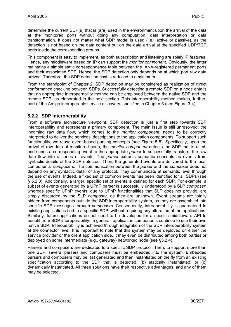
April 2005 Public
determine the current SDP(s) that is (are) used in the environment upon the arrival of the data at the monitored ports without doing any computation, data interpretation or data transformation. It does not matter what SDP model is used (i.e., active or passive), as the detection is not based on the data content but on the data arrival at the specified UDP/TCP ports inside the corresponding groups.
This component is easy to implement, as both subscription and listening are solely IP features. Hence, any middleware based on IP can support the monitor component. Obviously, the latter maintains a simple static correspondence table between the IANA-registered permanent ports and their associated SDP. Hence, the SDP detection only depends on at which port raw data arrived. Therefore, the SDP detection cost is reduced to a minimum.
From the standpoint of Chapter 2, SDP detection may be considered as realization of direct conformance checking between SDPs. Successfully detecting a remote SDP on a node entails that an appropriate interoperability method can be employed between the native SDP and the remote SDP, as elaborated in the next section. This interoperability method makes, further, part of the Amigo interoperable service discovery, specified in Chapter 3 (see Figure 3-4).
5.2.2 SDP interoperability From a software architecture viewpoint, SDP detection is just a first step towards SDP interoperability and represents a primary component. The main issue is still unresolved: the incoming raw data flow, which comes to the monitor component, needs to be correctly interpreted to deliver the services’ descriptions to the application components. To support such
. The communication between the parser and the composer does not depend on any syntactic detail of any protocol. semantic level through the use of events. Indeed, a fixed set of common events has been identified for all SDPs (see § 5.2.3). Additionally, a larger, specific set of events is defined for each SDP. For example, a subset of events generated by a SLP composer, whereas specific U not provide, are simply discarded by the SLP composer, as they are unknown. Event streams are totally
edicated to a specific SDP protocol. Then, to support more than
functionality, we reuse event-based parsing concepts (see Figure 5-5). Specifically, upon the arrival of raw data at monitored ports, the monitor component detects the SDP that is used, and sends a corresponding event to the appropriate parser to successfully transform the raw data flow into a series of events. The parser extracts semantic concepts as events from syntactic details of the SDP detected. Then, the generated events are delivered to the local components’ composers
They communicate at
UPnP parser is successfully understood by a PnP events, due to UPnP functionalities that SLP does
hidden from components outside the SDP interoperability system, as they are assembled into specific SDP messages through composers. Consequently, interoperability is guaranteed to existing applications tied to a specific SDP, without requiring any alteration of the applications. Similarly, future applications do not need to be developed for a specific middleware API to benefit from SDP interoperability. In general, application components continue to use their own native SDP. Interoperability is achieved through integration of the SDP interoperability system at the connector level. It is important to note that this system may be deployed on either the service provider or the client application side. It may even be distributed among both parties or deployed on some intermediate (e.g., gateway) networked node (see §5.2.4).
Parsers and composers are done SDP, several parsers and composers must be embedded into the system. Embedded parsers and composers may be: (a) generated and then instantiated on the fly from an existing specification according to the SDP that is detected; (b) statically instantiated; or (c) dynamically instantiated. All three solutions have their respective advantages, and any of them may be selected.
Amigo IST-2004-004182 90/227
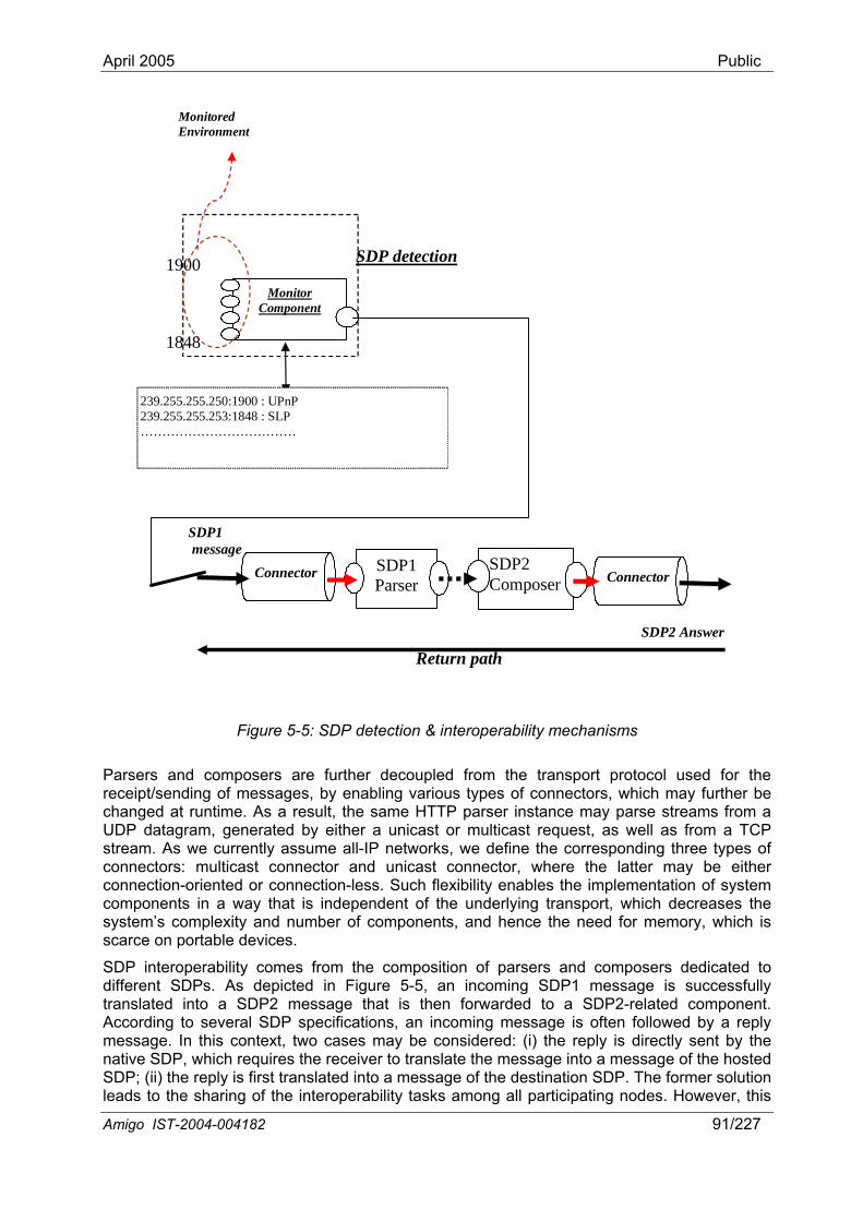
April 2005 Public
Monitored Environment
SDP detection
Monitor Component
1900
1848
239.255.255.250:1900 : UPnP 239.255.255.253:1848 : SLP ………………………………
SDP1 Parser
Connector
SDP1 message
SDP2 Composer Connector
Return path SDP2 Answer
Figure 5-5: SDP detection & interoperability mechanisms
Parsers and composers are further decoupled from the transport protocol used for the receipt/sending of messages, by enabling various types of connectors, which may further be changed at runtime. As a result, the same HTTP parser instance may parse streams from a UDP datagram, generated by either a unicast or multicast request, as well as from a TCP stream. As we currently assume all-IP networks, we define the corresponding three types of connectors: multicast connector and unicast connector, where the latter may be either connection-oriented or connection-less. Such flexibility enables the implementation of system
of the underlying transport, which decreases the onents, and hence the need for memory, which is
into a SDP2 message that is then forwarded to a SDP2-related component. According to several SDP specifications, an incoming message is often followed by a reply message. In this context, two cases may be c i) the reply is directly sent by the native SDP, which requires the receiver to translate the message into a message of the hosted SDP; (ii) the reply is first translated into a message of the destination SDP. The former solution leads to the sharing of the interoperability tasks among all participating nodes. However, this
components in a way that is independentsystem’s complexity and number of compscarce on portable devices.
SDP interoperability comes from the composition of parsers and composers dedicated to different SDPs. As depicted in Figure 5-5, an incoming SDP1 message is successfully translated
onsidered: (
Amigo IST-2004-004182 91/227
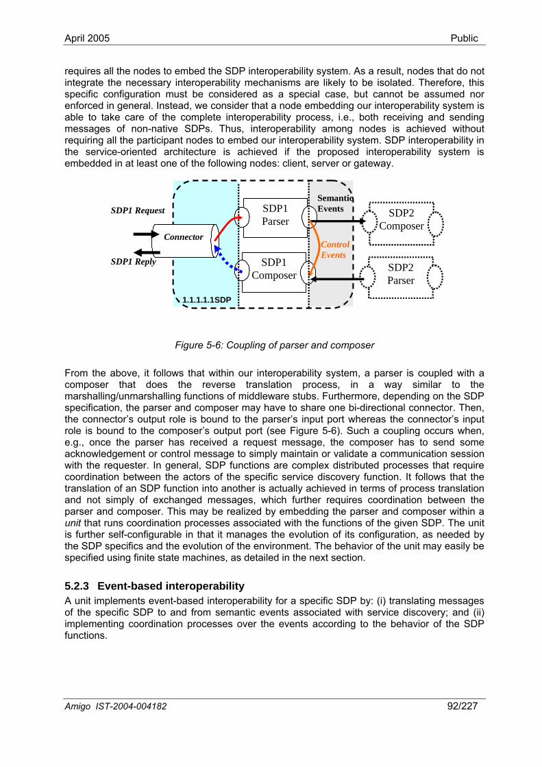
April 2005 Public
requires all the nodes to embed the SDP interoperability system. As a result, nodes that do not integrate the necessary interoperability mechanisms are likely to be isolated. Therefore, this specific configuration must be considered as a special case, but cannot be assumed nor enforced in general. Instead, we consider that a node embedding our interoperability system is able to take care of the complete interoperability process, i.e., both receiving and sending messages of non-native SDPs. Thus, interoperability among nodes is achieved without requiring all the participant nodes to embed our interoperability system. SDP interoperability in the service-oriented architecture is achieved if the proposed interoperability system is embedded in at least one of the following nodes: client, server or gateway.
Amigo IST-2004-004182 92/227
SDP2 Parser
SDP2 Composer
Connector
SDP1 Parser
SDP1 Composer
1.1.1.1.1 SDP
ControlEvents
SDP1 Reply
SDP1 Request Semantic Events
Figure 5-6: Coupling of parser and composer
From the above, it follows that within our interoperability system, a parser is coupled with a composer that does the reverse translation process, in a way similar to the marshalling/unmarshalling functions of middleware stubs. Furthermore, depending on the SDP specification, the parser and composer may have to share one bi-directional connector. Then, the connector’s output role is bound to the parser’s input port whereas the connector’s input role is bound to the composer’s output port (see Figure 5-6). Such a coupling occurs when, e.g., once the parser has received a request message, the composer has to send some acknowledgement or control message to simply maintain or validate a communication session with the requester. In general, SDP functions are complex distributed processes that require coordination between the actors of the specific service discovery function. It follows that the translation of an SDP function into another is actually achieved in terms of process translation and not simply of exchanged messages, which further requires coordination between the parser and composer. This may be realized by embedding the parser and composer within a unit that runs coordination processes associated with the functions of the given SDP. The unit is further self-configurable in that it manages the evolution of its configuration, as needed by the SDP specifics and the evolution of the environment. The behavior of the unit may easily be specified using finite state machines, as detailed in the next section.
5.2.3 Event-based interoperability A unit implements event-based interoperability for a specific SDP by: (i) translating messages of the specific SDP to and from semantic events associated with service discovery; and (ii) implementing coordination processes over the events according to the behavior of the SDP functions.
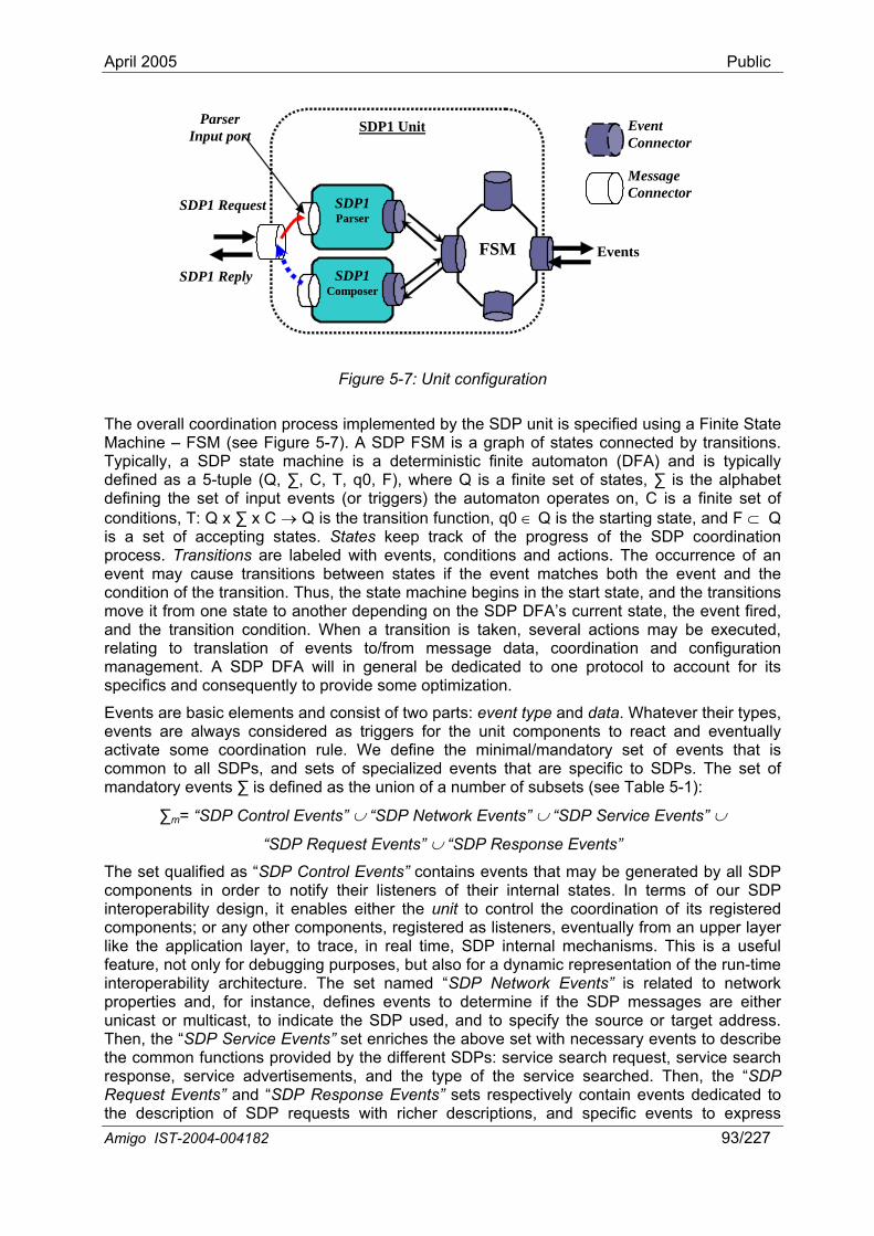
April 2005 Public
SDP1 Reply
SDP1 Request
Events
SDP1 Unit
SDP1 Composer
SDP1 Parser
FSM
Event Connector
Message Connector
Parser Input port
Figure 5-7: Unit configuration
The overall coordination process implemented by the SDP unit is specified using a Finite State FSM (see Figure 5-7). A SDP FSM f states connected by transitions.
utomaton (DFA) and is typically (Q, ∑, C, T, q0, F), where Q is a finite set of states, ∑ is the alphabet
defining the set of input events (or triggers) th erates on, C is a finite set of conditions, T: Q x ∑ x C → Q is the transition fu nd F ⊂ Q is a set of accepting states. States keep tra DP coordination process. Transitions are labeled with events, ccurrence of an
t and the ion. Thus, the state mach tate, and the transitions
move it from one state to another depending on tate, the event fired, and the transition condition. When a transition relating to translation of events to/from me d configuration management. A SDP DFA will in general be l to account for its specifics and consequently to provide some opt
nts and consist of two parts: ys considered as triggers for t and eventually
activate some coordination rule. We define events that is common to all SDPs, and sets of specialized to SDPs. The set of mandatory events ∑ is defined as the union of a Table 5-1):
∑m= “SDP Control Events” ∪ “SDP Netw Events” ∪
“SDP Request Events” ∪
The set qualified as “SDP Control Events” cont generated by all SDP to notify their listeners tes. In terms of our SDP it enables either the un coordination of its registered er components, register ventually from an upper layer
like the application layer, to trace, in real time echanisms. This is a useful feature, not only for debugging purposes, but al epresentation of the run-time interoperability architecture. The set named “ ents” is related to network properties and, for instance, defines events t messages are either unicast or multicast, to indicate the SDP used, and to specify the source or target address. Then, the “SDP Service Even ecessary events to describe the common functions provided by the different SDPs: service search request, service search response, service advertisements, and the type of the service searched. Then, the “SDP Request Events” and “SDP Response Events” sets respectively contain events dedicated to the description of SDP requests with richer descriptions, and specific events to express
Machine – Typically, a SDP state machine is a deterministic f
is a graph oinite a
defined as a 5-tuple e automaton op
∈nction, q0 Q is the starting state, ack of the progress of the Sconditions and actions. The o
event may cause transitions between states if the eventcondition of the transit
matches both the evenine begins in the start s the SDP DFA’s current s is taken, several actions may be executed,ssage data, coordination an
dedicated to one protocoimization.
Events are basic elemeevents are alwa
event type and data. Whatever their types, the unit components to reac
the minimal/mandatory set of events that are specific number of subsets (see
ork Events” ∪ “SDP Service
“SDP Response Events”
ains events that may becomponents in order of their internal stainteroperability design, components; or any oth
it to control theed as listeners, e, SDP internal m
so for a dynamic rSDP Network Ev
o determine if the SDP
ts” set enriches the above set with n
Amigo IST-2004-004182 93/227
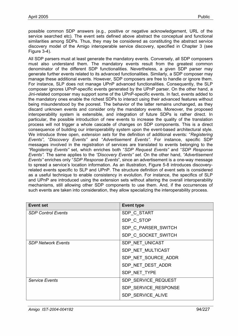
April 2005 Public
possible common SDP answers (e.g., positive or negative acknowledgement, URL of the service searched etc). The event sets defined above abstract the conceptual and functional similarities among SDPs. Thus, they may be considered as constituting the abstract service discovery model of the Amigo interoperable service discovery, specified in Chapter 3 (see Figure 3-4).
All SDP parsers must at least generate the mandatory events. Conversely, all SDP composers must also understand them. The mandatory events result from the greatest common denominator of the different SDP functionalities. Nevertheless, a given SDP parser may generate further events related to its advanced functionalities. Similarly, a SDP composer may manage these additional events. However, SDP composers are free to handle or ignore them. For instance, SLP does not manage UPnP advanced functionalities. Consequently, the SLP composer ignores UPnP-specific events generated by the UPnP parser. On the other hand, a Jini-related composer may support some of the UPnP-specific events. In fact, events added to the mandatory ones enable the richest SDPs to interact using their advanced features without being misunderstood by the poorest. The behavior of the latter remains unchanged, as they discard unknown events and consider only the mandatory events. Moreover, the proposed interoperability system is extensible, and integration of future SDPs is rather direct. In particular, the possible ality of the translation process will not trigger a whole cascade of changes on SDP components. This is a direct
introduction of new events to increase the qu
consequence of building our interoperability system upon the event-based architectural style. We introduce three open, extension sets for the definition of additional events: “Registering Events”, “Discovery Events” and “Advertisement Events”. For instance, specific SDP messages involved in the registration of services are translated to events belonging to the “Registering Events” set, which enriches both “SDP Request Events” and “SDP Response Events”. The same applies to the “Discovery Events” set. On the other hand, “Advertisement Events” enriches only “SDP Response Events”, since an advertisement is a one-way message to spread a service’s location information. As an illustration, Figure 5-8 introduces discovery-related events specific to SLP and UPnP. The structure definition of event sets is considered as a useful technique to enable consistency in evolution. For instance, the specifics of SLP and UPnP are introduced using the extension sets without altering the overall interoperability mechanisms, still allowing other SDP components to use them. And, if the occurrences of such events are taken into consideration, they allow specializing the interoperability process.
Event set Event type
SDP Control Events SDP_C_START
SDP_C_STOP
SDP_C_PARSER_SWITCH
SDP_C_SOCKET_SWITCH
SDP Network Events NET_UNICAST
RCE_ADDR
SDP_NET_DEST_ADDR
SDP_NET_TYPE
SDP_
SDP_NET_MULTICAST
SDP_NET_SOU
Service Events SDP_SERVICE_REQUEST
SDP_SERVICE_RESPONSE
SDP_SERVICE_ALIVE
Amigo IST-2004-004182 94/227
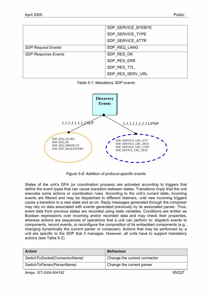
April 2005 Public
SDP_SERVICE_BYEBYE
SDP_SERVICE_TYPE
SDP_SERVICE_ATTR
SDP Request Events SDP_REQ_LANG
SDP Response Events SDP_RES_OK
SDP_RES_ERR
SDP_RES_TTL,
SDP_RES_SERV_URL
Table 5-1: Mandatory SDP events
DiscoveryEvents
Amigo IST-2004-004182 95/227
SDP_REQ_SCOPE SDP_REQ_ID SDP_REQ_PREDICAT SDP_NET_REQUESTERS
1.1.1.1.1.1.1.2 SLP 1.1.1.1.1.1.1.1 UPNP
SDP_SERVICE_URL_EVT SDP_SERVICE_URL_DESC SDP_SERVICE_URL_CTRL SDP_DEVICE_URL_DESC
Figure 5-8: Addition of protocol-specific events
States of the unit’s DFA (or coordination process) are activated according to triggers that define the event types that can cause transition between states. Transitions imply that the unit executes some actions or coordination rules. A the unit’s current state, incoming events are filtered and may be dispatched to different listeners, until new incoming triggers cause a transi he composer may rely on data associated with events generated previously by its associated parser. Thus, event data from previous states are recorded using state variables. Conditions are written as
ccording to
tion to a new state and so on. Reply messages generated through t
Boolean expressions over incoming and/or recorded data and may check their properties, whereas actions are sequences of operations that a unit can perform to: dispatch events to components, record events, or reconfigure the composition of its embedded components (e.g., changing dynamically the current parser or composer). Actions that may be performed by a unit are specific to the SDP that it manages. However, all units have to support mandatory actions (see Table 5-2).
Action Behaviour
SwitchToSocket(ConnectorName) Change the current connector
SwitchToParser(ParserName) Change the current parser
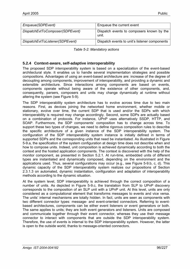
April 2005 Public
Enqueue(SDPEvent) Enqueue the current event
DispatchEvtToComposer(SDPEvent) Dispatch events to composers known by the unit.
DispatchEvtToListener(SDPEvent) Dispatch events to unit’s listener components
Table 5-2: Mandatory actions
5.2.4 Context-aware, self-adaptive interoperability The proposed SDP interoperability system is based on a specialization of the event-based architectural style. It enables us to handle several implementation strategies and possible compositions. Advantages of using an event-based architecture are: increase of the degree of decoupling among components, improvement of interoperability, and providing a dynamic and extensible architecture. Since intcomponents operate without being
eractions among components are based on events, ents, and,
consequently, parsers, composers and units may change dynamically at runtime without altering the system (s
The SDP interoperability sy lve across time due to two main reasons. First, as devices vironment, whether mobile or stationary, evolve over time, the current SDP that is used and/or the SDPs with which interoperability is required may change accordingly. Second, some SDPs are actually based on a combination of protoc For instance, UPnP uses alternatively SSDP, HTTP, and SOAP. Furthermore, the SDP components’ composition has to change across time. To support these two types of changes, we need to define rigorous composition rules to describe
tance is initially defined in terms of upported SDPs and the corresponding units that need be instantiated. As illustrated in Figure -9.a, the specifica ration at design time does not describe when and ow to compose u tion is achieved dynamically according to both the ontext and the ho p of the onitor componen presented in Section 5.2.1. At run-time, embedded units of different pes are instantia cally composed, depending on the environment and the pplications used. Thus, several configurations may occur (e.g., see Figure 5-9.b, c, d). This ynamic capacity of the SDP interoperability system realizes our propositions of Section
he correct composition of a
are totally hidden. In fact, units are seen as components with two different connector types: message- and event-oriented connectors. Referring to event-
e either event listeners or event generators or both.
aware of the existence of other compon
ee Figure 5-9).
stem architecture has to evojoining the networked home en
ols.
the specific architecture of a given instance of the SDP interoperability system. The configuration of the SDP interoperability system inss5 tion of the system configu
nits. Indeed, unit composihcm
sted application components. The context is discovered with the helt, as ed and dynamity t
ad2.3.1.3 on automated, dynamic instantiation, configuration and adaptation of interoperability methods according to the dynamic situation.
At the system level, SDP interoperability is achieved through tnumber of units. As depicted in Figure 5-9.c, the translation from SLP to UPnP discovery corresponds to the composition of an SLP unit with a UPnP unit. At this level, units are only considered as a computational element that transforms messages to events and vice versa. The units’ internal mechanisms
based architectures, components can bThe same applies to units; they are both event generators and listeners. Units are composed and communicate together through their event connector, whereas they use their message connector to interact with components that are outside the SDP interoperability system. Therefore, the use of events is internal to the SDP interoperability system. However, the latter is open to the outside world, thanks to message-oriented connectors.
Amigo IST-2004-004182 96/227
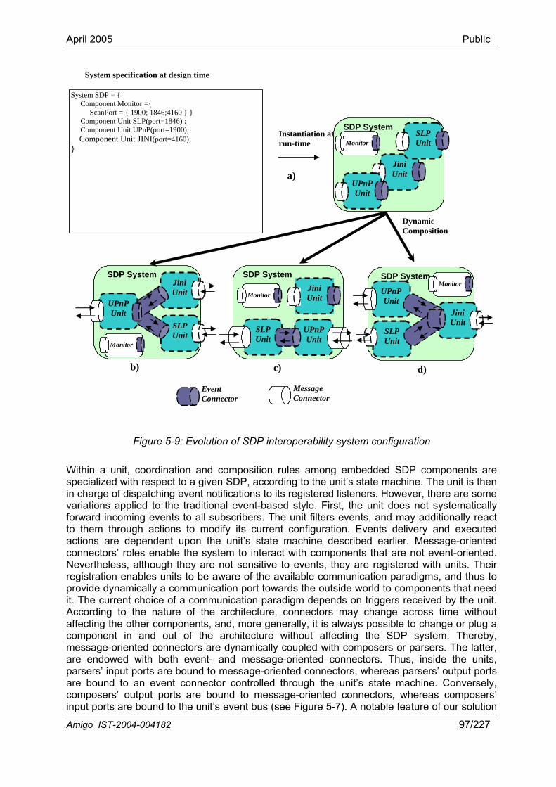
April 2005 Public
Event Connector
Message Connector
Dynamic Composition
System SDP = { Component Monitor ={ ScanPort = { 1900; 1846;4160 } } Component Unit SLP(port=1846) ; Component Unit UPnP(port=1900); Component Unit JINI(port=4160); }
System specification at design time
Instantiation at run-time
Jini Unit
SLP Unit
UPnP Unit
SDP System
Monitor
Jini Unit
SDP System
UPnPUnit
SLP Unit Monitor
a)
SLP Unit
UPnPUnit
Jini Unit
SDP System
Monitor
b) c)
Jini Unit
SLP Unit
UPnP Unit
SDP System Monitor
d)
Figure 5-9: Evolution of SDP interoperability system configuration
Within a unit, coordination and composition rules among embedded SDP components are specialized with respect to a given SDP, according to the unit’s state machine. The unit is then in charge of dis here are some variations applied to th
input ports are bound to the unit’s event bus (see Figure 5-7). A notable feature of our solution
patching event notifications to its registered listeners. However, te traditional event-based style. First, the unit does not systematically
forward incoming events to all subscribers. The unit filters events, and may additionally react to them through actions to modify its current configuration. Events delivery and executed actions are dependent upon the unit’s state machine described earlier. Message-oriented connectors’ roles enable the system to interact with components that are not event-oriented. Nevertheless, although they are not sensitive to events, they are registered with units. Their registration enables units to be aware of the available communication paradigms, and thus to provide dynamically a communication port towards the outside world to components that need it. The current choice of a communication paradigm depends on triggers received by the unit. According to the nature of the architecture, connectors may change across time without affecting the other components, and, more generally, it is always possible to change or plug a component in and out of the architecture without affecting the SDP system. Thereby, message-oriented connectors are dynamically coupled with composers or parsers. The latter, are endowed with both event- and message-oriented connectors. Thus, inside the units, parsers’ input ports are bound to message-oriented connectors, whereas parsers’ output ports are bound to an event connector controlled through the unit’s state machine. Conversely, composers’ output ports are bound to message-oriented connectors, whereas composers’
Amigo IST-2004-004182 97/227
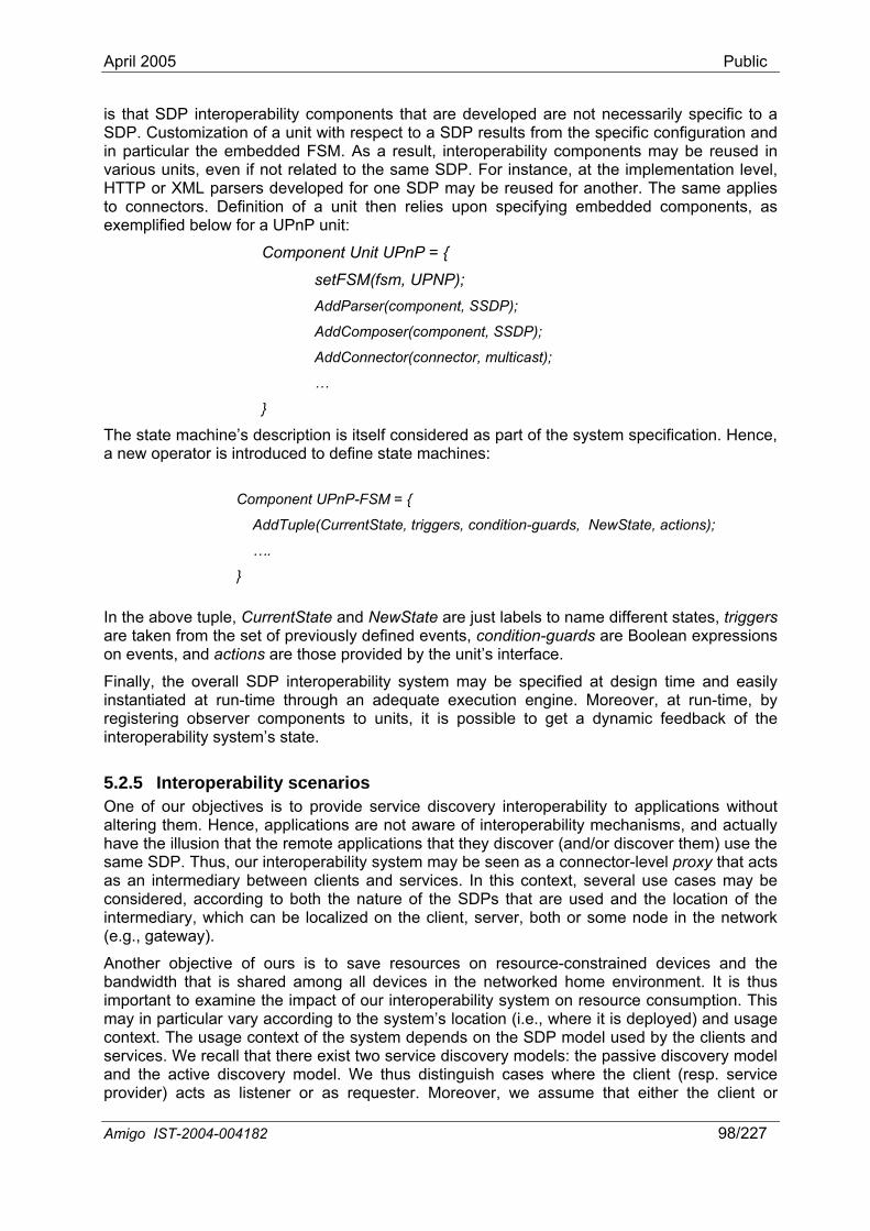
April 2005 Public
is that SDP interoperability components that are developed are not necessarily specific to a SDP. Customization of a unit with respect to a SDP results from the specific configuration and
e specified at design time and easily
ined devices and the networked home environment. It is thus
rrentState, triggers, condition-guards, NewState, actions);
in particular the embedded FSM. As a result, interoperability components may be reused in various units, even if not related to the same SDP. For instance, at the implementation level, HTTP or XML parsers developed for one SDP may be reused for another. The same applies to connectors. Definition of a unit then relies upon specifying embedded components, as exemplified below for a UPnP unit:
Component Unit UPnP = {
setFSM(fsm, UPNP); AddParser(component, SSDP);
AddComposer(component, SSDP);
AddConnector(connector, multicast);
…
}
The state machine’s description is itself considered as part of the system specification. Hence, a new operator is introduced to define state machines:
Component UPnP-FSM = {
AddTuple(Cu
In the above tuple, CurrentState and NewState are just labels to name different states, triggers are taken from the set of previously defined events, condition-guards are Boolean expressions on events, and actions are those provided by the unit’s interface.
Finally, the overall SDP interoperability system may b
….
}
instantiated at run-time through an adequate execution engine. Moreover, at run-time, by registering observer components to units, it is possible to get a dynamic feedback of the interoperability system’s state.
5.2.5 Interoperability scenarios One of our objectives is to provide service discovery interoperability to applications without altering them. Hence, applications are not aware of interoperability mechanisms, and actually have the illusion that the remote applications that they discover (and/or discover them) use the same SDP. Thus, our interoperability system may be seen as a connector-level proxy that acts as an intermediary between clients and services. In this context, several use cases may be considered, according to both the nature of the SDPs that are used and the location of the intermediary, which can be localized on the client, server, both or some node in the network (e.g., gateway).
Another objective of ours is to save resources on resource-constrabandwidth that is shared among all devices in theimportant to examine the impact of our interoperability system on resource consumption. This may in particular vary according to the system’s location (i.e., where it is deployed) and usage context. The usage context of the system depends on the SDP model used by the clients and services. We recall that there exist two service discovery models: the passive discovery model and the active discovery model. We thus distinguish cases where the client (resp. service provider) acts as listener or as requester. Moreover, we assume that either the client or
Amigo IST-2004-004182 98/227
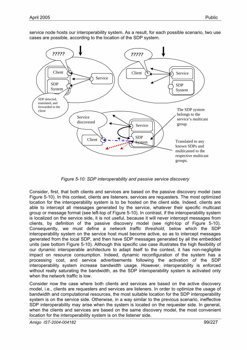
April 2005 Public
service node hosts our interoperability system. As a result, for each possible scenario, two use cases are possible, according to the location of the SDP system.
Amigo IST-2004-004182 99/227
Client
SDP System
Service
?????
SDP detected, translated, and forwarded to the
Client
SDP System
Service
?????
client
Client SDP System
Service
The SDP system belongs to the service’s multicast group.
Service discovered
Translated to any known SDPs and multicasted to the respective multicast groups.
Figure 5-10: SDP interoperability and passive service discovery
Consider, first, that both clients and services are based on the passive discovery model (see
-10). Although this specific use case illustrates the high flexibility of
vertisements following the activation of the SDP inte p is enforced with t activated only whe t
Figure 5-10). In this context, clients are listeners, services are requesters. The most optimized location for the interoperability system is to be hosted on the client side. Indeed, clients are able to intercept all messages generated by the service, whatever their specific multicast group or message format (see left-top of Figure 5-10). In contrast, if the interoperability system is localized on the service side, it is not useful, because it will never intercept messages from clients, by definition of the passive discovery model (see right-top of Figure 5-10). Consequently, we must define a network traffic threshold, below which the SDP interoperability system on the service host must become active, so as to intercept messages generated from the local SDP, and then have SDP messages generated by all the embedded units (see bottom Figure 5our dynamic interoperable architecture to adapt itself to the context, it has non-negligible impact on resource consumption. Indeed, dynamic reconfiguration of the system has a processing cost, and service ad
ro erability system increase bandwidth usage. However, interoperability ou really saturating the bandwidth, as the SDP interoperability system isn he network traffic is low.
Consider now the case where both clients and services are based on the active discovery model, i.e., clients are requesters and services are listeners. In order to optimize the usage of bandwidth and computational resources, the most suitable location for the SDP interoperability system is on the service side. Otherwise, in a way similar to the previous scenario, ineffective SDP interoperability may arise when the system is located on the requester side. In general, when the clients and services are based on the same discovery model, the most convenient location for the interoperability system is on the listener side.

April 2005 Public
It may be the case that the clients and services are based on different discovery models. If the clients are based on the active model and services are based on the passive one, then both clients and services generate SDP messages. Interoperability is guaranteed without additional resource cost. Nevertheless, some subtleties arise. Hosting of the SDP interoperability system on the client side means that the client benefits from the advertisements of remote services. But, the client’s requests will not reach remote t are based on different SDPs, if they are not interoperable (i.e., they do not host our interoperability system). On the contrary, if the services embed the SDP interoperability system and not the clients, requests from the latter w rvices’ advertisements originating from SDPs distinct than the one hosted. Although, in this case, interoperability is not as effective as expected, clients and services do interact. Furthermore, interoperability effectiveness may be improved if the bandwidth is under-utilized, thanks to the SDP system’s reconfigurability.
Conversely, when clients are based on the passive model and services are based on the active model, both clients and services are listeners. Once again, we are faced with the recurrent ineffective discovery interoperability. However, in this particular case, dynamic reconfiguration of the SDP interoperability system does not resolve the clients’ inability to discover services, since there is no node initiating SDP-related communication. There is no way to resolve this issue, considering our constraint not to alter the behavior of SDPs, clients and services. On the other hand, this specific case is unlikely to happen. In current systems, in practice, clients are always able to generate requests.
Summarizing, irrespectively of the service discovery model used by clients and services, we are able to guarantee a minimum level of interoperability. Then, depending on the environment, the bandwidth usage may be increased to enable higher interoperability. The basic idea is to provide a quasi-full interoperability as long as the bandwidth usage enables it. Then, interoperability degradation may occur according to the traffic. Furthermore, by design, our interoperability system is independent of its host. So, it is not mandatory for the SDP interoperability system to be deployed on the client or service host. The system may be deployed on a dedicated networked node, depending on the specific networked home environment. Such a dedicated node may in particular translate messages generated within the environment from any SDP to messages handled by any other SDP, according to the traffic condition. Obviously, this specific configuration generates additional traffic, and is onlvalid as long as there is enough bandwidth. It is further more appropriate to qualify such a configuration as an “interoperable environment” rather than as an interoperable device.
protopestaddarcserinte
radesknoprotocol, alt ically, unlike the SDP
add
services tha
ill be taken into consideration by services, whereas clients will not be aware of se
y
5.3 Interaction protocol interoperability This section discusses how the interoperability mechanisms introduced in the previous section to specifically achieve SDP interoperability may further be applied to achieve interaction
tocol interoperability, hence leading to core mechanisms for middleware interoperability on of IP. Our approach to interaction protocol interoperability directly applies the principles ablished in Chapter 2 on connector-level interoperability, since we there specifically ressed connectors realizing interaction protocols. According to the service-oriented
hitectural style, interaction protocols identify two application components: a client and a vice. The former requires and the latter provides some functionality. Although for any raction the protocol identifies the client and the service, the client and service roles can be
reversed in another interaction.
P ctically, the service runs at an address that may be known by the client, either statically at ign time or dynamically using some service discovery protocol. However, in both cases, wledge of the service’s address does not mean knowledge of the service’s interaction
hough it may be assumed when known statically. Specifdetection mechanism, the interaction protocol detection cannot be simply based on the
ress of the interacting parties. Achieving interaction protocol interoperability further raises Amigo IST-2004-004182 100/227
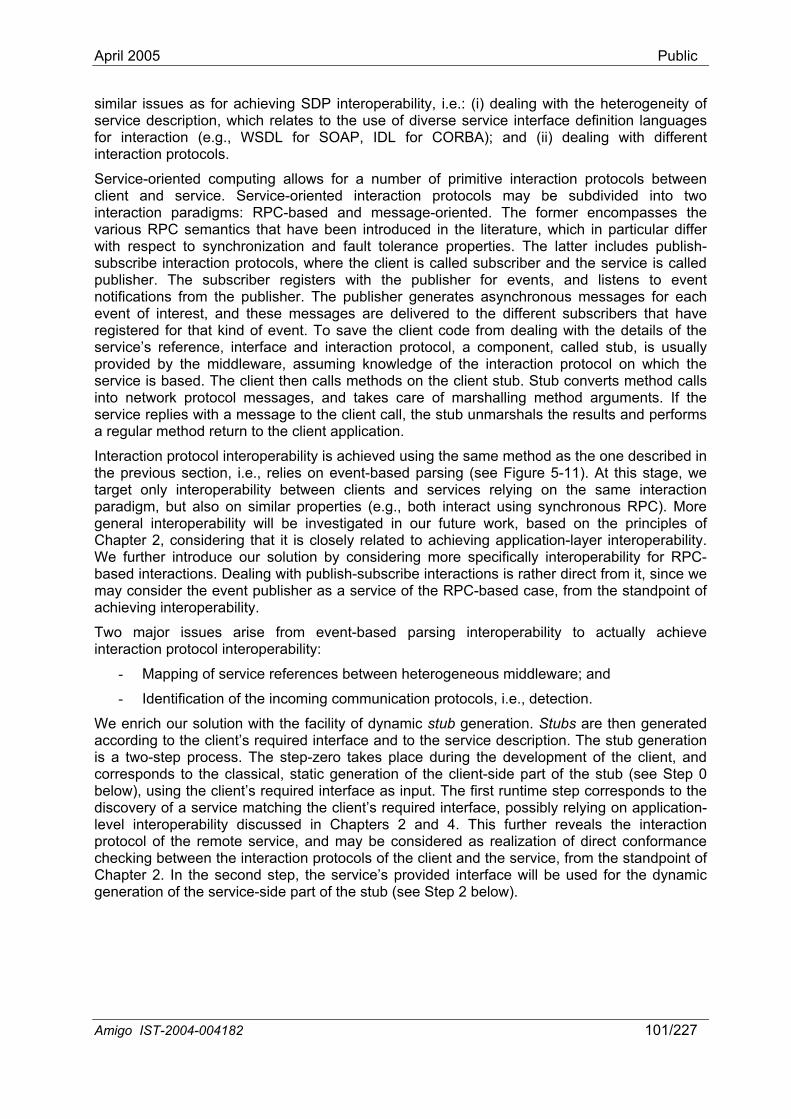
April 2005 Public
simserfor inte
clieintevarwith sh-
noteve d these messages are delivered to the different subscribers that have
(see Figure 5-11). At this stage, we target only interoperability between clients and services relying on the same interaction
.g., both interact using synchronous RPC). More in our future work, based on the principles of
We n c stub generation. Stubs are then generated according to the service description. The stub generation
tocols of the client and the service, from the standpoint of
ilar issues as for achieving SDP interoperability, i.e.: (i) dealing with the heterogeneity of vice description, which relates to the use of diverse service interface definition languages interaction (e.g., WSDL for SOAP, IDL for CORBA); and (ii) dealing with different raction protocols.
Service-oriented computing allows for a number of primitive interaction protocols between nt and service. Service-oriented interaction protocols may be subdivided into two raction paradigms: RPC-based and message-oriented. The former encompasses the ious RPC semantics that have been introduced in the literature, which in particular differ respect to synchronization and fault tolerance properties. The latter includes publi
subscribe interaction protocols, where the client is called subscriber and the service is called publisher. The subscriber registers with the publisher for events, and listens to event
ifications from the publisher. The publisher generates asynchronous messages for each nt of interest, an
registered for that kind of event. To save the client code from dealing with the details of the service’s reference, interface and interaction protocol, a component, called stub, is usually provided by the middleware, assuming knowledge of the interaction protocol on which the service is based. The client then calls methods on the client stub. Stub converts method calls into network protocol messages, and takes care of marshalling method arguments. If the service replies with a message to the client call, the stub unmarshals the results and performs a regular method return to the client application.
Interaction protocol interoperability is achieved using the same method as the one described in the previous section, i.e., relies on event-based parsing
paradigm, but also on similar properties (egeneral interoperability will be investigatedChapter 2, considering that it is closely related to achieving application-layer interoperability. We further introduce our solution by considering more specifically interoperability for RPC-based interactions. Dealing with publish-subscribe interactions is rather direct from it, since we may consider the event publisher as a service of the RPC-based case, from the standpoint of achieving interoperability.
Two major issues arise from event-based parsing interoperability to actually achieve interaction protocol interoperability:
- Mapping of service references between heterogeneous middleware; and
- Identification of the incoming communication protocols, i.e., detection.
e rich our solution with the facility of dynami the client’s required interface and to
is a two-step process. The step-zero takes place during the development of the client, and corresponds to the classical, static generation of the client-side part of the stub (see Step 0 below), using the client’s required interface as input. The first runtime step corresponds to the discovery of a service matching the client’s required interface, possibly relying on application-level interoperability discussed in Chapters 2 and 4. This further reveals the interaction protocol of the remote service, and may be considered as realization of direct conformance checking between the interaction proChapter 2. In the second step, the service’s provided interface will be used for the dynamic generation of the service-side part of the stub (see Step 2 below).
Amigo IST-2004-004182 101/227
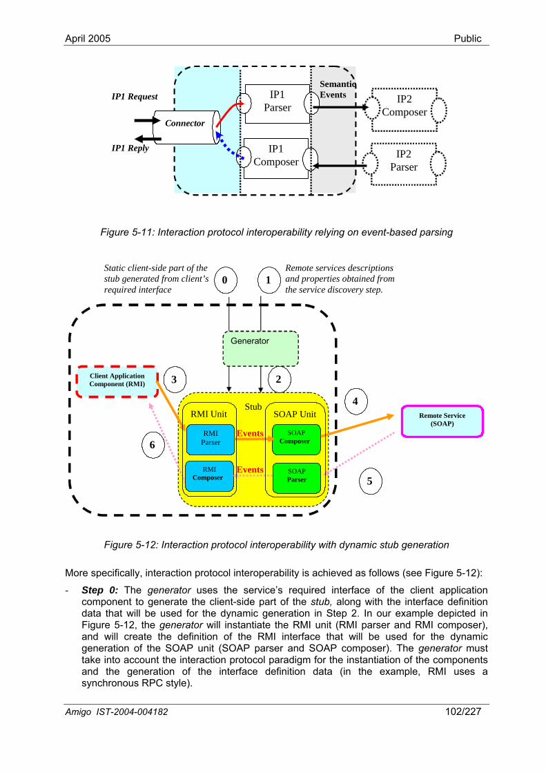
April 2005 Public
Amigo IST-2004-004182 102/227
IP2 Parser
IP2 Composer
Connector
IP1 Parser
IP1 Composer
IP1 Reply
IP1 Request Semantic Events
Figure 5-11: Interaction protocol interoperability relying on event-based parsing
Static client-side part of the stub generated from clie 10 and properties obtained from
Remote services descriptions nt’s
required interface the service discovery step.
Generator
Stub Remote Service
(SOAP)
Client Application Component (RMI)
RMI Parser
SOAP Composer
23
4
Events
5
6
SOAP Parser
RMI Composer
Events
RMI Unit SOAP Unit
Figure 5-12: Interaction protocol interoperability with dynamic stub generation
More specifically, interaction protocol interoperability is achieved as follows (see Figure 5-12):
- Step 0: The generator uses the service’s required interface of the client application component to generate the client-side part of the stub, along with the interface definition data that will be used for the dynamic generation in Step 2. In our example depicted in Figure 5-12, the generator will instantiate the RMI unit (RMI parser and RMI composer), and will create the definition of the RMI interface that will be used for the dynamic generation of the SOAP unit (SOAP parser and SOAP composer). The generator must take into account the interaction protocol paradigm for the instantiation of the components and the generation of the interface definition data (in the example, RMI uses a synchronous RPC style).
April 2005 Public
- Step 1: The service’s description and reference are obtained from the service discovery step. This step is tightly related to the discovery process and the corresponding SDP interoperability system. The service will be described in the service interface definition language (e.g., the SOAP service will be described in WSDL).
- Step 2: The generator dynamically instantiates the stub part dedicated to the remote he
(obtained from Step 0) from the service description in Step 1). In our example, we assume that the SOAP remote
ence to the remote service.
mentioned issues, i.e.: (i) the mismatch
n LDAP syntax, among which the provided Java interface.
rvice, Amigo services developed in Java can easily be provided as OSGi services and packed in OSGi bundles. However, OSGi service registration and lookup allow only discovery and use of services collocated in the same OSGi platform, hence the proposal of specialized bundles offering communication services across several OSGi platforms.
service from the service’s description and reference. This part amounts to instantiating tappropriate unit, taking into account the information on the client’s required interface
and the remote service’s interaction protocol paradigm (available
service follows the synchronous RPC style, like the RMI client application component.
- The stub acts as the intermediary between the client and the rStep 3&4: emote service. Specifically, the stub presents to the client application component the same interface as the remote service, but in a compatible format. The client may therefore invoke service operations. Invocations are forwarded to the remote service in the appropriate format required by the service through the stub that holds the refer
- Steps 5&6: The remote service, in its turn, may reply to the client with its native protocol, as if the client were running a matching interaction protocol, thanks to event-based parsing interoperability.
Note that the proposed solution resolves the two aforebetween service references that are specific to interaction protocols (retrieval of the service reference in Step 1, generation based on the service reference in Step 2, and use of the service reference in Step 4); and (ii) the identification of the incoming communication protocol needed to select the appropriate parser (instantiation of the parser in Step 2 and use in Step 5), together with the enforcement of the appropriate communication paradigm (stub generation based on communication paradigm in Steps 0 and 2). Nevertheless, this assumes a known mapping between the required and provided interface, which actually relies on application-layer interoperability, as discussed in Chapters 2 and 4.
5.4 OSGi-based interoperability This section shows how the OSGi technology can be used as a support for the development and deployment of services in Amigo. Such services may belong to the middleware layer (like interoperability methods/mechanisms) or to the application layer. In this section, we focus on supporting the interoperability methods for interaction protocols. This approach is however applicable for many middleware services.
OSGi provides its own definition of service. An OSGi platform allows deployable elements, called "bundles" to be remotely installed from http servers. When started, a bundle will possibly provide "services". A service is any Java object. The service registry allows:
- Registering an object as a service, that is, to associate this object with a list of properties described in a
- Look up services matching target criteria.
Additionally, the OSGi framework takes care of the life cycle of services and automatically suppresses the references of services registered by a bundle when this bundle is stopped. As any Java object can be registered as an OSGi se
Amigo IST-2004-004182 103/227
April 2005 Public
In the following, we call "server" a program that expose d "client" a service. Note that "server" con set o s, and "client" for other services.
Section 5.4.1 shows how OSGi services could help developing protocol-independent "Amigo-aware" clients and servers, so that the choice of network protocols or SDPs can be decided at run-time. Section 5.4.2 focuses roperability methods between legacy services, and shows how Amigo can take a e of standard OSG ices to pr nhanced interoperability methods.
5.4.1 Export and binding factories We rely on the fundamental concepts of "export factories" and "binding factories". An "export factory" is a service that makes a Java object remotely available. To this purpose, an export factory provides a method (called "export"). The result of "Exporting a service" is a "binding d scr hat can be serialized and published using a discovery protocol. This "binding description" contains all useful to the service, such as the host and here ice Exporting a service may or not involve the con of some dedicated objects on the server. Symmetrically, a "binding factory" is u he client to bind t ice, given a "binding description". A binding factory provid ding description as parameter and returns an object called "proxy" or "stub". then be used by the client to communicate with the remote object. Export inding factories can be packaged in OSGi bundles as follows:
- The generic export bundle provides interfaces of the export process.
- Specialized bundles (the RMI export bundle, the Axis export bundle,…) provide implementations of the export factory interface based on a specific protocol and a
- The generic bindin rocess.
- Specialized bundles (the RMI binding bundle, the Axis binding bundle…) provide implementations of the binding factory interface based on a specific protocol and a
y.
ing on platform
OSGi nodes, and provide the possibility for already installed applications to export their services or access services using this new protocol. This method makes it possible to expose
s a (OSGi) service on the network, anin reality, the same program will be program that wants to use this
in what cerns a f service
on intedvantag i serv opose e
e iption" telements to allow a client to bind can be found, the protocols etc... port w the serv
structionsed on t
es a "bind" method that takes a bino a given serv
This stub can factories and b
specific technology.
g bundle provides interfaces of the binding p
specific technolog
A subset of these bundles will be installed on every OSGi node, depending on which type of application bundles it will host and what are the capacities of the hardware platform. It may be desirable to limit the memory print on embedded devices. Also, depending on the network configuration, a protocol may be preferred (in some circumstances, http protocol may be preferred because of firewall problems, whereas when possible RMI may be preferred for performance reasons). Therefore, an OSGi platform running on a PDA and hosting only client applications could host only binding bundles, and be limited to one binding technology (e.g., ksoap) whereas a platform running on a PC and hosting a variety of server and client applications would host several export and binding factories, so as to maximize interoperability with other nodes.
As an illustration, Figure 5-13 depicts 3 running OSGi platforms. Platform C contains a "server" bundle that exports an object. As 2 export factories are present on this server, the object can be exported through both RMI and SOAP protocols. The client runnA will use SOAP binding, whereas the client running on platform B uses RMI. The binding process may involve the downloading of specific code (contained here in "proxy bundles").
The proposed approach facilitates the introduction of new protocols, as this involves only writing the corresponding export and binding factories and packing those as OSGi bundles that register the factories as services. These bundles can then be installed on already existing
Amigo IST-2004-004182 104/227
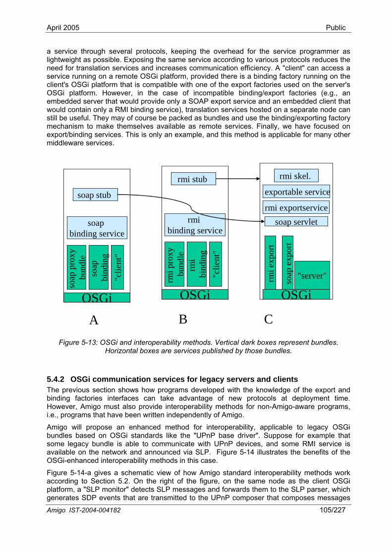
April 2005 Public
a service through several protocols, keeping the overhead for the service programmer as lightweight as possible. Exposing the same service according to various protocols reduces the need for translation services and increases communication efficiency. A "client" can access a service running on a remote OSGi platform, provided there is a binding factory running on the client's OSGi platform that is compatible with one of the export factories used on the server's OSGi platform. However, in the case of incompatible binding/export factories (e.g., an embedded server that would provide only a SOAP export service and an embedded client that would contain only a RMI binding service), translation services hosted on a separate node can still be useful. They may of course be packed as bundles and use the binding/exporting factory mechanism to make themselves available as remote services. Finally, we have focused on
This is only an example, and this method is applicable for many other export/binding services.middleware services.
Amigo IST-2004-004182 105/227
soap
exp
ort
soap
bind
ing
OSGi
"clie
nt"
OSGi
rmi e
rmi skel.
soap binding service
rmi exportservicesoap servlet
exportable service
rmi binding service
rmi stub
soap stub
xpor
t
OSGi"server"
soap
pr
bund
leoxy
rmbi
ndii ng
"clie
nt"
rmi p
rbu
ndlox
y e
A B C
Figure 5-13: OSGi and interoperability methods. Vertical dark boxes represent bundles. Horizontal boxes are services published by those bundles.
5.4.2 OSGi communication services for legacy servers and clients The previous section shows how programs developed with the knowledge of the export and binding factories interfaces can take advantage of new protocols at deployment time. However, Amigo must also provide interoperability methods for non-Amigo-aware programs, i.e., programs that have been written independently of Amigo.
Amigo will propose an enhanced method for interoperability, applicable to legacy OSGi bundles based on OSGi standards like the "UPnP base driver". Suppose for example that some legacy bundle is able to communicate with UPnP devices, and some RMI service is available on the network and announced via SLP. Figure 5-14 illustrates the benefits of the OSGi-enhanced interoperability methods in this case.
Figure 5-14-a gives a schematic view of how Amigo standard interoperability methods work according to Section 5.2. On the right of the figure, on the same node as the client OSGi platform, a "SLP monitor" detects SLP messages and forwards them to the SLP parser, which
er that composes messages generates SDP events that are transmitted to the UPnP compos

April 2005 Public
5.5 Related work Service discovery protocol heterogeneity is a key challenge in the mobile computing domain. If
architecture associated with reflection features allows mobile
r-level interoperability, elaborating concrete, optimized conformance relations and
arties. The proposed interoperability system is flexible and extensible. In particular, our system may
t or service host or even on an intermediate networked node.
lementing a prototype of the interoperability system to assess its
services are advertised with SDPs different than those supported by mobile clients, mobile clients are unable to discover their environment and are consequently isolated. Due to the highly dynamic nature of the mobile network, available networked resources change very often. This requires a very efficient mechanism to monitor the mobile environment without generating additional resource consumption. In this context, inspection and adaptation functionalities offered by reflective middleware are not adequate to support service discovery protocol interoperability, as they induce too high resource consumption. Section 5.2 has addressed this challenge, providing an efficient solution to achieving interoperability among heterogeneous service discovery protocols. Our solution is specifically designed for Amigo dynamic home networks, which requires both minimizing resource consumption, and introducing lightweight mechanisms that may be adapted easily to any platform. An implementation will soon be released to validate both its design and efficiency.
Once services are discovered, applications further need to use the same interaction protocol to allow unanticipated connections and interactions with them. In this context, the ReMMoC reflective middleware introduces a quite efficient solution to interaction protocol interoperability. The plug-indevices to adapt dynamically their interaction protocols (i.e., publish/subscribe, RPC etc.). Furthermore, [GBS03b] proposes to use ReMMoC together with WSDL34 for providing an abstract definition of the remote component’s functionalities. Client applications may then be developed against this abstract interface without worrying about service implementation details. However, the solution discussed in [GBS03b] suffers from a major constraint: service and client must agree on a unique WSDL description. But, once again, in a dynamic mobile network, the client does not know the execution context. Therefore, it is not guaranteed to find exactly the expected service. Client applications have to find the most appropriate service instance that matches the abstract requested service. Such an issue is resolved through application-layer interoperability methods discussed in Chapters 2 and 4.
5.6 Discussion This chapter has introduced the base Amigo solution to achieving middleware-layer interoperability, which decomposes into realizing service discovery protocol and interaction protocol interoperability. This solution follows the principles established in Chapter 2 on connectoassociated interoperability methods for SDP and interaction protocols, two well-defined classes of connectors. Our solution builds on latest results in the middleware and software engineering domains, and relies on event-based parsing interoperability. Briefly stated, middleware interoperability is achieved by translating core middleware functionalities (i.e., service discovery and interaction) to/from semantic events. As not any middleware offers the same level of functionalities, interoperability is achieved up to the greatest common denominator of the functionalities offered by the various middleware of the interacting p
be deployed on the clien
We are currently impperformance. Early results are encouraging, although the effectiveness of our solution depends on the environment, as discussed in Section 5.2.5. In addition, an efficient version of the system may be implemented using latest technologies like OSGi.
n Language, http://www.w3.org/TR/wsdl20/ 34 W3C, Web Services Descriptio
Amigo IST-2004-004182 107/227

April 2005 Public
6 InConsumcover mattracticases stand adependPC-cenfunctiodomain the PC-centred dat econsuma DVDMoreovnetworinstallaaround
The attsystemautomanetworCE dom ts towards an industry agreement for an integrated and inte pAlliancbased or developmemust take protocols for mto enforce inteanother issue trends, in ordoperation. Howopen problem direction, especially by the UPnP Forum.
The next sections hnologies and present standardization efforts that can be used as a base framework for the integration of the CE domain in Amigo (Section 6.1). Second, the problem of QoS provided over a heterogeneous home network is analyzed, introducon multimedia interop ithin Amigo are highlighted, the Amigo multimedia streaming architecture is pre with the Amigo abstract reference service architecture defined in Chapter 3 (Section 6.3). Finally, conclusions close this chapter (Section 6.4).
6.1 BackgrounAn industrythrough severa Alliance (DLNA) brings together major companies, and intends to provide such an agreement based on open design guidelines and standards. In few words, the Digital Living Network Alliance (DLNA) vision [DLN04a, DLN04b] integrates the Internet, mo ds through a seamless,
tegration of the CE domain er Electronics (CE), e.g., DVD players, TV screens, game consoles, stereo sets, etc., ost of the entertainment that is enjoyed at home, and therefore represent a major
on to the typical consumer. Nowadays, CE provide specific functionalities, in most related to multimedia content, usually in the form of separate specialized products that round the house, communicating with one or two other products by means of media-ent interfaces. On the other hand, the typical home network today is data-based and tered, and emphasizes sharing printers and Internet access within a house. While
nal, it is of limited interest to the typical consumer. Thus, in the average home the CE remains as a set of specialized networks with no communication with
a n twork. The former lacks easiness in installation and seamless interaction, leaving to the er the configuration and usually wired connection of those networks (i.e., connection of
player to a TV screen and a Hi-Fi, using the available audio and video interfaces). er, transferring multimedia content from the Internet or the PC to the specialized CE
ks is not a smooth operation in this kind of home (i.e., recording on compatible media, tion of specialized cards in the PC, connecting cables, and/or moving equipment might be required).
ractiveness of the CE domain to the typical user must be enforced by the Amigo home by adding value to the existing functionalities. This shall be achieved by providing tic dynamic configuration, interoperability and seamless operation for the CE devices
ked in the home, without diminishing Quality of Service (QoS). Some companies of the ain are already making effor
ro erable network at home through alliances and consortiums. The Digital Living Network e (DLNA)35 brings together major companies and intends to provide such an agreement on open design guidelines and standards. In turn, these provide a solid base f
nt of smoothly interoperable applications. The development of the Amigo system into account the industry’s state of the art as well as the new and well-established
ultimedia transmission, namely, RTP/RTCP, HTTP, RTSP, UPnP AV, in order roperability and performance. Discovery of CE devices and their services is
that must be considered, together again with the industry’s state of the art and er to achieve automatic dynamic configuration and an overall seamless ever, integration of QoS in a network with different CE products remains an
, although efforts are being made in this
introduce, first, those well-known tec
ing UPnP-QoS as a base solution (Section 6.2). Then, once considerations erability w
sented, in accordance
d agreement for an integrated and interoperable home network is presently enforced
l alliances and consortiums. The Digital Living Network
bile and broadcast islan
35 DLNA, http://www.dlna.org
Amigo IST-2004-004182 109/227
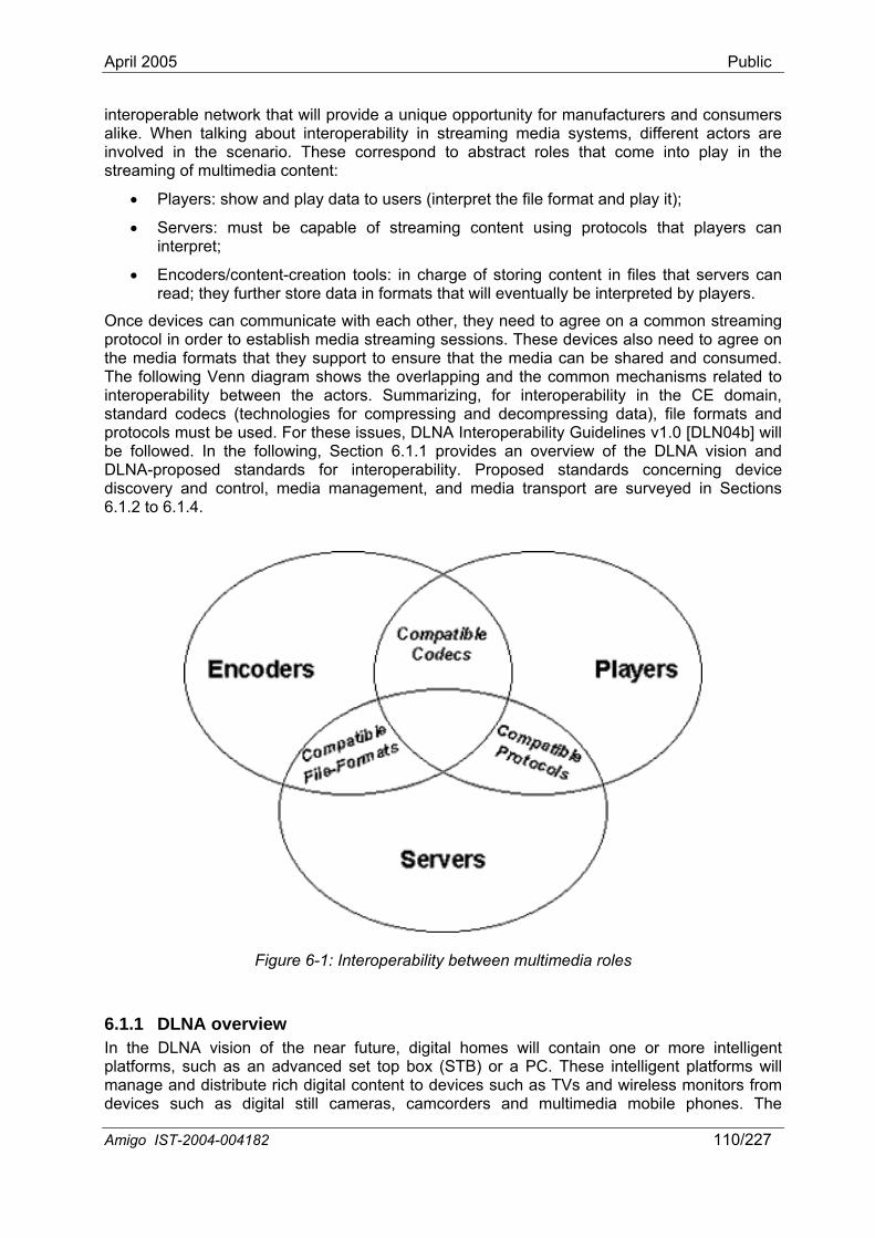
April 2005 Public
interoperable netw pportunity for manufacturers and consumers alike. When talkin y in streaming media systems, different actors are involved in the s pond to abstract roles that come into play in the streaming of multi
•
Once dprotocothe meThe fo diagram shows the overlapping and the common mechanisms related to inter CE domain, stan e formats and protocols m Guidelines v1.0 [DLN04b] will be followedDLNA-propodiscovery and6.1.2 to 6.1.4.
ork that will provide a unique og about interoperabilitcenario. These corresmedia content:
• Players: show and play data to users (interpret the file format and play it);
• Servers: must be capable of streaming content using protocols that players can interpret;
Encoders/content-creation tools: in charge of storing content in files that servers can read; they further store data in formats that will eventually be interpreted by players.
evices can communicate with each other, they need to agree on a common streaming l in order to establish media streaming sessions. These devices also need to agree on dia formats that they support to ensure that the media can be shared and consumed. llowing Venn
operability between the actors. Summarizing, for interoperability in thedard codecs (technologies for compressing and decompressing data), fil
ust be used. For these issues, DLNA Interoperability . In the following, Section 6.1.1 provides an overview of the DLNA vision and sed standards for interoperability. Proposed standards concerning device
control, media management, and media transport are surveyed in Sections
Figure 6-1: Interoperability between multimedia roles
6.1.1 DLNA overview In the DLNA vision of the near future, digital homes will contain one or more intelligent platforms, such as an advanced set top box (STB) or a PC. These intelligent platforms will manage and distribute rich digital content to devices such as TVs and wireless monitors from devices such as digital still cameras, camcorders and multimedia mobile phones. The
Amigo IST-2004-004182 110/227
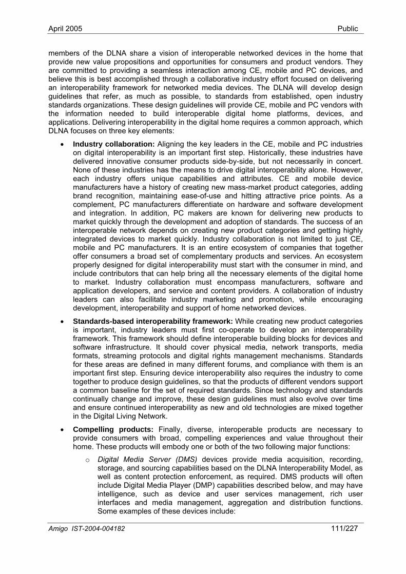
April 2005 Public
members of the DLNA share a vision of interope in the home that provide new value p ns and opportunities ct vendors. They are committed to providing a seamless interaction among CE, mobile and PC devices, and believe this is best accomplished through a collaborative industry effort focused on delivering an interoperability framework for networked media devices. The DLNA will develop design guidelines that refer, as much as possible, to standards from established, open industry standards organizati s will pro and PC vendors with the information needed to build interoperable digital home platforms, devices, and applications. Delivering interoperability in the digital hom on approach, which DLNA focuses on th ments:
• Industry collaboration: Aligning the key lead e and PC industries on digital interoperability is an important first step. Historically, these industries have delivered innovative consumer products side-b rily in concert. None of thes as the means to drive digital interoperability alone. However, each industry offers unique capabilities and attributes. CE and mobile device manufacturers have a history of creating new ategories, adding brand recognition, maintaining ease-of-use rice points. As a complement, s differentiate on hardware and software development and integration. In addition, PC makers are known for delivering new products to market quick he development and he success of an interoperable creating nd getting highly integrated de quickly. Indus ited to just CE, mobile and PC manufacturers. It is an entire ecosystem of companies that together offer consumers a broad set of coproperly designed for h the consumer in mind, and include contributors that can help bring all the necessary elements of the digital home
device interoperability also requires the industry to come
l, as well as content protection enforcement, as required. DMS products will often include Digital Media Player (DMP) capabilities described below, and may have
d us ment, rich user interfaces and media management, aggregation and distribution functions. Some examples of these devices include:
rable networked devices for consumers and produropositio
ons. These design guideline
ree key ele
vide CE, mobile
e requires a comm
ers in the CE, mobil
y-side, but not necessae industries h
mass-market product cand hitting attractive p
PC manufacturer
ly through t network depends on vices to market
adoption of standards. Tnew product categories atry collaboration is not lim
mplementary products and services. An ecosystem digital interoperability must start wit
to market. Industry collaboration must encompass manufacturers, software and application developers, and service and content providers. A collaboration of industry leaders can also facilitate industry marketing and promotion, while encouraging development, interoperability and support of home networked devices.
• Standards-based interoperability framework: While creating new product categories is important, industry leaders must first co-operate to develop an interoperability framework. This framework should define interoperable building blocks for devices and software infrastructure. It should cover physical media, network transports, media formats, streaming protocols and digital rights management mechanisms. Standards for these areas are defined in many different forums, and compliance with them is an important first step. Ensuring together to produce design guidelines, so that the products of different vendors support a common baseline for the set of required standards. Since technology and standards continually change and improve, these design guidelines must also evolve over time and ensure continued interoperability as new and old technologies are mixed together in the Digital Living Network.
• Compelling products: Finally, diverse, interoperable products are necessary to provide consumers with broad, compelling experiences and value throughout their home. These products will embody one or both of the two following major functions:
o Digital Media Server (DMS) devices provide media acquisition, recording, storage, and sourcing capabilities based on the DLNA Interoperability Mode
intelligence, such as device an er services manage
Amigo IST-2004-004182 111/227
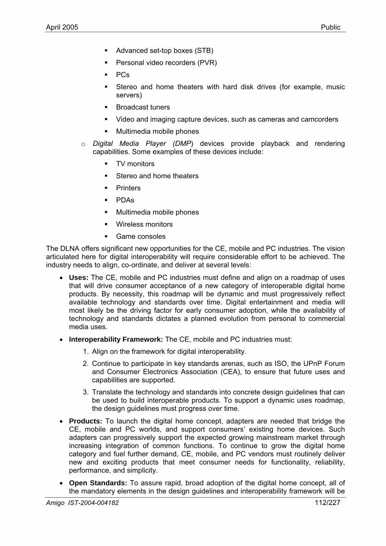
April 2005 Public
Advanced set xes (ST
Personal video recorders (PVR)
mple, music
Broadcast tuners
and imaging capture devices, such as cameras and camcorders
te, and deliver at several levels:
tries must:
1. Align on the framework for digital interoperability.
2. Continue to participate in key standards arenas, such as ISO, the UPnP Forum and Consumer Electronics Association (CEA), to ensure that future uses and capabilities are supported.
3. Translate the technology and standards into concrete design guidelines that can be used to build interoperable products. To support a dynamic uses roadmap, the design guidelines must progress over time.
• Products: To launch the digital home concept, adapters are needed that bridge the CE, mobile and PC worlds, and support consumers’ existing home devices. Such adapters can progressively support the expected growing mainstream market through increasing integration of common functions. To continue to grow the digital home category and fuel further demand, CE, mobile, and PC vendors must routinely deliver new and exciting products that meet consumer needs for functionality, reliability, performance, and simplicity.
• Open Standards: To assure rapid, broad adoption of the digital home concept, all of in the design guidelines and interoperability framework will be
-top bo B)
PCs
Stereo and home theaters with hard disk drives (for exaservers)
Video
Multimedia mobile phones
o Digital Media Player (DMP) devices provide playback and rendering capabilities. Some examples of these devices include:
TV monitors
Stereo and home theaters
Printers
PDAs
Multimedia mobile phones
Wireless monitors
Game consoles
The DLNA offers significant new opportunities for the CE, mobile and PC industries. The vision articulated here for digital interoperability will require considerable effort to be achieved. The industry needs to align, co-ordina
• Uses: The CE, mobile and PC industries must define and align on a roadmap of uses that will drive consumer acceptance of a new category of interoperable digital home products. By necessity, this roadmap will be dynamic and must progressively reflect available technology and standards over time. Digital entertainment and media will most likely be the driving factor for early consumer adoption, while the availability of technology and standards dictates a planned evolution from personal to commercial media uses.
• Interoperability Framework: The CE, mobile and PC indus
the mandatory elementsAmigo IST-2004-004182 112/227
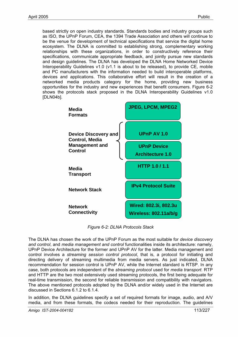
April 2005 Public
Amigo IST-2004-004182 113/227
based strictly on open industry standards. Standards bodies and industry groups such as ISO, the UPnP Forum, CEA, the 1394 Trade Association and others will continue to be the venue for development of technical specifications that service the digital home ecosystem. The DLNA is committed to establishing strong, complementary working relationships with these organizations, in order to constructively reference their specifications, communicate appropriate feedback, and jointly pursue new standards and design guidelines. The DLNA has developed the DLNA Home Networked Device Interoperability Guidelines v1.0 (v1.1 is about to be released), to provide CE, mobile and PC manufacturers with the information needed to build interoperable platforms, devices and applications. This collaborative effort will result in the creation of a networked media products category for the home, providing new business opportunities for the industry and new experiences that benefit consumers. Figure 6-2 shows the protocols stack proposed in the DLNA Interoperability Guidelines v1.0 [DLN04b].
ry
t of the streaming protocol used for media transport. RTP
Figure 6-2: DLNA Protocols Stack
The DLNA has chosen the work of the UPnP Forum as the most suitable for device discoveand control, and media management and control functionalities inside its architecture: namely, UPnP Device Architecture for the former and UPnP AV for the latter. Media management and control involves a streaming session control protocol, that is, a protocol for initiating and directing delivery of streaming multimedia from media servers. As just indicated, DLNA recommendation for session control is UPnP AV, while the Internet standard is RTSP. In any case, both protocols are independenand HTTP are the two most extensively used streaming protocols, the first being adequate for real-time transmission, the second for reliable transmission and compatibility with navigators. The above mentioned protocols adopted by the DLNA and/or widely used in the Internet are discussed in Sections 6.1.2 to 6.1.4.
In addition, the DLNA guidelines specify a set of required formats for image, audio, and A/V media, and from these formats, the codecs needed for their reproduction. The guidelines
Wired: 802.3i, 802.3u Wireless: 802.11a/b/g
IPv4 Protocol Suite
HTTP 1.0 / 1.1
UPnP Device Architecture 1.0
UPnP AV 1.0
Control
Device Discovery and Control, Media Management and
JPEG, LPCM, MPEG2Media Formats
Media Transport
Network Stack
Network Connectivity
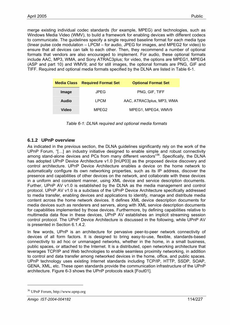
April 2005 Public
merge existing individual codec standards (for example, MPEG) and technologies, such as Windows Media Video (WMV), to build a framework for enabling devices with different codecs to communicate. The guidelines specify a single required baseline format for each media type (linear pulse code modulation – LPCM – for audio, JPEG for images, and MPEG2 for video) to ensure that all devices can talk to each other. Then, they recommend a number of optional formats that vendors are also encouraged to implement. For audio, these optional formats include AAC, MP3, WMA, and Sony ATRAC3plus; for video, the options are MPEG1, MPEG4 (ASP and part 10) and WMV9; and for still images, the optional formats are PNG, GIF and TIFF. Required and optional media formats specified by the DLNA are listed in Table 6-1.
Media Class Required Format Set Optional Format Set
Image JPEG PNG, GIF, TIFF
Audio LPCM AAC, ATRAC3plus, MP3, WMA
Video MPEG2 MPEG1, MPEG4, WMV9
Table 6-1: DLNA required and optional media formats
6.1.2 UPnP overview As indicated in the previous section, the DLNA guidelines significantly rely on the work of the
itiative designed to enable simple and robust connectivity
the DLNA as the media management and control
ards including TCP/IP, HTTP, SSDP, SOAP, GENA, XML, etc. These open standards provide the communication infrastructure of the UPnP
UPnP Forum, “[…] an industry inamong stand-alone devices and PCs from many different vendors”36. Specifically, the DLNA has adopted UPnP Device Architecture v1.0 [InUP03] as the proposed device discovery and control architecture. UPnP Device Architecture enables a device on the home network to automatically configure its own networking properties, such as its IP address, discover the presence and capabilities of other devices on the network, and collaborate with these devices in a uniform and consistent manner, using XML device and service description documents. Further, UPnP AV v1.0 is established by protocol. UPnP AV v1.0 is a subclass of the UPnP Device Architecture specifically addressed to media transfer, enabling devices and applications to identify, manage and distribute media content across the home network devices. It defines XML device description documents for media devices such as renderers and servers, along with XML service description documents for capabilities implemented by those devices. Furthermore, by defining capabilities relative to multimedia data flow in these devices, UPnP AV establishes an implicit streaming session control protocol. The UPnP Device Architecture is discussed in the following, while UPnP AV is presented in Section 6.1.4.2.
In few words, UPnP is an architecture for pervasive peer-to-peer network connectivity of devices of all form factors. It is designed to bring easy-to-use, flexible, standards-based connectivity to ad hoc or unmanaged networks, whether in the home, in a small business, public spaces, or attached to the Internet. It is a distributed, open networking architecture that leverages TCP/IP and Web technologies to enable seamless proximity networking, in addition to control and data transfer among networked devices in the home, office, and public spaces. UPnP technology uses existing Internet stand
architecture. Figure 6-3 shows the UPnP protocols stack [Fout01].
36 UPnP Forum, http://www.upnp.org
Amigo IST-2004-004182 114/227
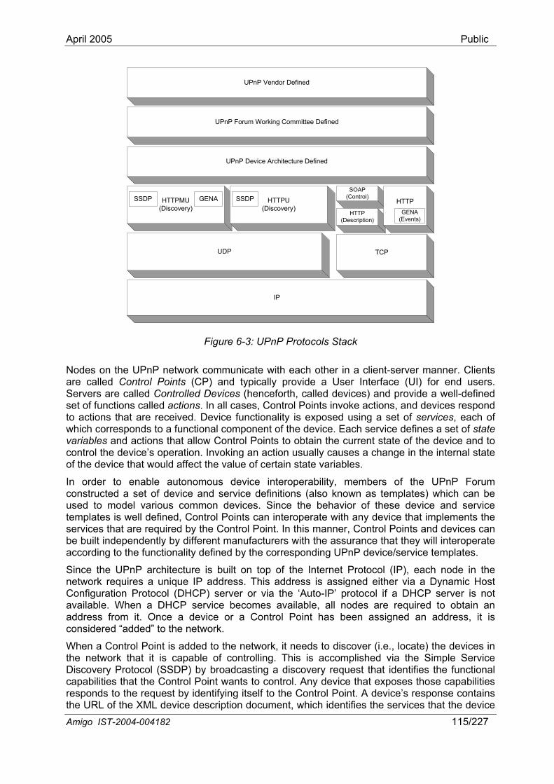
April 2005 Public
UPnP Vendor Defined
UPnP Forum Working Committee Defined
UPnP Device Architecture Defined
HTTPMU(Discovery)
HTTPU(Discovery)
SOAP(Control)
HTTP(Description)
UDP TCP
SSDP GENA SSDP
IP
HTTPGENA
(Events)
cols Stack
Nodes on the UPnP network communicate with each other in a client-server manner. Clients are called rol Points (CP) and typically provide a User Interface (UI) for end users. Servers are l-defined set of functions called action oints invoke actions, and devices respond to actions ed. ices, each of which corresponds to a func set of state variables and actions that al device and to control the device’s operation. Invoking an action usually causes a change in the internal state of the dev uld affec
In order to enable autonomous device interoperability, members oconstructe vice hich can be used to m s com these device and service templates o plements the services th required bybe built independently by different manufacturers with the assurance that they will interoperate according to the functionality defined by the corresponding UPnP device/service templates.
Since the UPnP architecture is rotocol (IP), each node in the network requires a unique IP address. This address is assigned either via a Dynamic Host
or via the ‘Auto-IP’ protocol if a DHCP server is not
is accomplished via the Simple Service Discovery Protocol (SSDP) by broadcasting a discovery request that identifies the functional capabilities that the Control Point wants to control. Any device that exposes those capabilities responds to the request by identifying itself to the Control Point. A device’s response contains the URL of the XML device description document, which identifies the services that the device
Figure 6-3: UPnP Proto
Contcalled Controlled Devices (henceforth, called de
s. In all cases, Control Pvices) and provide a wel
that are receiv Device functionality is exposed using a set of servtional component of the device. Each service defines a low Control Points to obtain the current state of the
ice that wo t the value of certain state variables.
f the UPnP Forum and service definitions (also known as templates) wmon devices. Since the behavior of
d a set of deodel variou
is well defined, Cat are
ntrol Points can interoperate with any device that im the Control Point. In this manner, Control Points and devices can
built on top of the Internet P
Configuration Protocol (DHCP) serveravailable. When a DHCP service becomes available, all nodes are required to obtain an address from it. Once a device or a Control Point has been assigned an address, it is considered “added” to the network.
When a Control Point is added to the network, it needs to discover (i.e., locate) the devices in the network that it is capable of controlling. This
Amigo IST-2004-004182 115/227
April 2005 Public
implements, as well as the specific actions and state variables that are supported by each service. By parsing th informcapabilitie e. This ts to interact with and contro ice. , the device may broadcast fi isting Control Points that e ntrolled. The notification includes ument, in the same way above fo
Once a C er particular device, the Control Point uses the Simple Object Access Protocol (SOAP) to invoke any of the actions exposed by the device’s services. The behavior of each action is well defined by the service template document. Alternatively, an event-bas scheme is supported. As the internal state of a device may change, either in response to an action or via some internal condition,
e is defined in each of the service templates that are supported by the device. be moderated, so that rapid changes in this
tate variable do not cause excessive network traffic.
6.1.3 Streaming protocols Streaming client technology that allows live or pre-recorded data to be transported in real time, p the network for traditional multimedia applications such as news, education, ertainment, advertising, and a lot of other uses. Streaming technology offers a significant improvement over the download-and-play approach to multimedia file distribution, because it allows t ient as a continuous flow with minimal delay before playback
There are several Internet protocols available for streaming data. In the following sections, we will briefly introduce RTP [Schu03] (a d ) (Section 6.1.3.1) and HTTP [Fiel99] (based on (Section 6.1.3.2). RTCP is a part of RTP and helps with lip synchronization and QoS Generally, a streaming protocol configures data into packets, with each packet that identifies its contents. The protocol to be used is usually determine d to have reliable or unreliable communication. DLNA recommendation for media transport is HTTP (see Figure 6-2), widely used in the Internet community. However,
TTP is the slowest of the protocols and would just serve the stream as fast as it could. HTTP does not have any concept of real-time transfer in it. Further d server take turns talking; no bi-directio n, at transport layer, UDP (not TCP required by HTTP) is the preferred transmission protocol for real-time streaming, because UDP is not troubled by (or is even aware of) dropped packets. UDP can send packets at a
n or the application's ability to receive them,
iss of each devic
ation, the Control Point is able to determine the exact allows a Control Point to determine if it wan
l a particular dev When a new device is added to the network an identification noti
a new device has bcation to the network. This notification informs exen added to the network and is available to be co
information as described
the URL of the new device’s description docr a device’s response.
ontrol Point has det mined that it wants to control a
ed communication
the device can inform one or more Control Points of the state change using the Generic Event Notification Architecture (GENA) protocol. With this protocol, Control Points that desire to be informed of state changes within a particular device must register with that device to receive event notifications. A given device may be monitored by multiple Control Points. When an internal state change occurs, the device sends an event notification to each Control Point that has registered with the device. This event notification includes an identification of the state variable that has changed, along with its new value. The set of state variables that are evented by the devicAdditionally, each evented state variable may s
is a server/ opening u
training, ent
he data to be delivered to the clcan begin.
erivative of UDP TCP) management.
header having a d by the nee
H, in HTTP, the client an
nal chatter is allowed. In additio
constant rate, regardless of network congestiowithout reducing throughput by retransmitting useless “late” packets. Weaknesses of HTTP lead us to survey alternative protocols as well.
6.1.3.1 Real-Time Transport Protocol / Real-Time Control Protocol (RTP / RTCP) The Real-Time Transport Protocol (RTP) [Schu03] is an Internet protocol standard that specifies a way for programs to manage the real-time transmission of multimedia data over either unicast or multicast network services. RTP combines its data transport with a control protocol (RTCP) [Schu03], which makes it possible to monitor data delivery in large multicast
Amigo IST-2004-004182 116/227
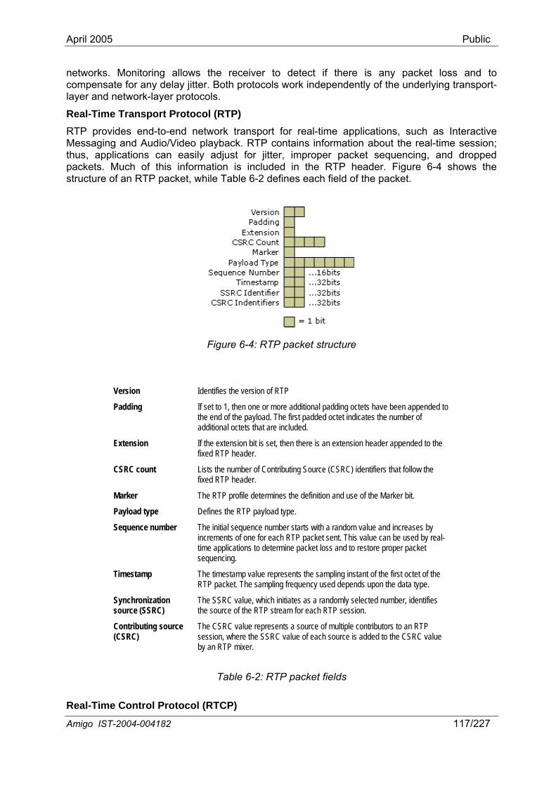
April 2005 Public
networks. Monitoring allows the receiver to detect if there is any packet loss and to compensate for any delay jitter. Both protocols work independently of the underlying transport-layer and network-layer protocols.
Real-Time Transport Protocol (RTP) RTP provides end-to-end network transport for real-time applications, such as Interactive Messaging and Audio/Video playback. RTP contains information about the real-time session; thus, applications can easily adjust for jitter, improper packet sequencing, and dropped packets. Much of this information is included in the RTP header. Figure 6-4 shows the structure of an RTP packet, while Table 6-2 defines each field of the packet.
Figure 6-4: RTP packet structure
Version Identifies the version of RTP
Padding If set to 1, then one or more additional padding octets have been appended to the end of the payload. The first padded octet indicates the number of
ded.
lications to determine packet loss and to restore proper packet
Real-Time Control Protocol (RTCP)
additional octets that are inclu
Extension If the extension bit is set, then there is an extension header appended to the fixed RTP header.
CSRC count Lists the number of Contributing Source (CSRC) identifiers that follow the fixed RTP header.
Marker The RTP profile determines the definition and use of the Marker bit.
Payload type Defines the RTP payload type.
Sequence number The initial sequence number starts with a random value and increases by increments of one for each RTP packet sent. This value can be used by real-time appsequencing.
Timestamp The timestamp value represents the sampling instant of the first octet of the RTP packet. The sampling frequency used depends upon the data type.
Synchronization source (SSRC)
The SSRC value, which initiates as a randomly selected number, identifies the source of the RTP stream for each RTP session.
Contributing source The CSRC value represents a source of multiple contributors to an RTP (CSRC) session, where the SSRC value of each source is added to the CSRC value
by an RTP mixer.
Table 6-2: RTP packet fields
Amigo IST-2004-004182 117/227
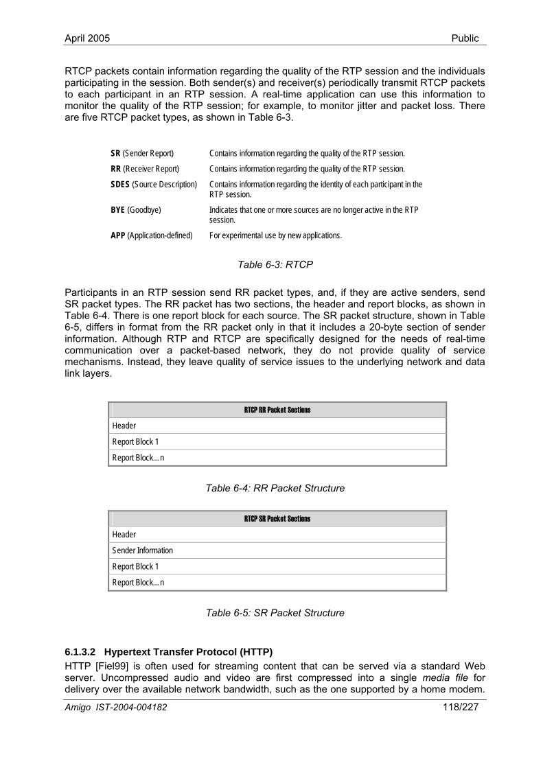
April 2005 Public
RTCP packets contain information regarding the quality of the RTP session and the individuals particip to eac to monitor the quality of the RTP session; for example, to monitor jitter and packet loss. There are e
er Report) Contains information regarding the quality of the RTP session.
s that one or more sources are no longer active in the RTP session.
n-defined) For experimental use by new applications.
t blocks, as shown in
ating in the session. Both sender(s) and receiver(s) periodically transmit RTCP packetsh participant in an RTP session. A real-time application can use this information
fiv RTCP packet types, as shown in Table 6-3.
SR (Sender Report) Contains information regarding the quality of the RTP session.
RR (Receiv
SDES (Source Description) Contains information regarding the identity of each participant in the RTP session.
BYE (Goodbye) Indicate
APP (Applicatio
Table 6-3: RTCP
Participants in an RTP session send RR packet types, and, if they are active senders, send SR packet types. The RR packet has two sections, the header and reporTable 6-4. There is one report block for each source. The SR packet structure, shown in Table 6-5, differs in format from the RR packet only in that it includes a 20-byte section of sender information. Although RTP and RTCP are specifically designed for the needs of real-time communication over a packet-based network, they do not provide quality of service mechanisms. Instead, they leave quality of service issues to the underlying network and data link layers.
RTCP RR Packet Sections
Header
Report Block 1
Report Block…n
Table 6-4: RR Packet Structure
RTCP SR Packet Sections
Header
Sender Information
Report Block 1
Report Block…n
Table 6-5: SR Packet Structure
6.1.3.2 HTserver. Uncompressed audio and video are first compressed into a single media file for delivery over the available network bandwidth, such as the one supported by a home modem.
Hypertext Transfer Protocol (HTTP) TP [Fiel99] is often used for streaming content that can be served via a standard Web
Amigo IST-2004-004182 118/227
April 2005 Public
This media file is then placed on the Web server. Next, a Web page containing the media file's URL is created and placed on the same Web server. This Web page, when activated, launches the client-side player and downloads the media file. So far, the actions are identical to those in a download-and-play case. The difference lies in how the client functions. Unlike in a download-and-play scenario, the streaming client starts playing the audio or video while it is being downloaded, after only a few seconds wait for buffering, which is the process of collecting the first part of a media file before playing. This small backlog of information, or buffer, allows the media to continue playing uninterrupted even during periods of high network congestion. With this delivery method, the client retrieves data as fast as the Web server, network and itself will allow without reg te parameter of the compressed stream. Only certain media file formats support
HTTP operates on top of TCP transmission, which handles all the data transfers. Optimized for non-real-time ap ch as file transfer and remote lo P's goal is to maximize the data transfer rate, while ensuring overall stability and high throughput of the entire network. To achieve this, using an algorithm called slow start, TCP first sends data at a low data rate, and then gradually increases the rate until the destination reports packet loss. TCP then assumes it has hit the bandwidth limit or network congestion, and returns to sending data at a low data rate, then gradually increasin ing the proces achieves reliable data transfer by re-transmitting lost pa , it cannot ensure that all resent packets will arrive at the client in time to be played in the media stream.
6.1.4 Streaming session control protocols We have seen how to perform delivery of real-time data, including streaming audio and video. However, a control protocol cting delivery of streaming multimedia from media servers. Here is where the streaming session protocols come into the
Figure 6-2) (Section 6.1.4.2). However, since we have included RTuse 6.1.4.1). RTSP does not deliver data, though the RTSP connection may be used to tunnel RT r SP will likely be used tog hout the other. Next to the w vant to streaming multimedia communication, concerning delivery in the Internet-based network (Section 6.1.4.3).
ream which may be sent via a separate
scription (e.g., SDP
responses. The most important RTSP commands are:
ard to the bit-rathis type of "progressive playback".
plications, su g-in, TC
g, thus, repeatckets. However
s. TCP
is needed for initiating and dire
play. DLNA recommendation for session control is UPnP AV (see P/RTCP in our previous discussion, it would be
ful to add a real-time alternative for controlling the session: RTSP [Schu98] (Section
P t affic for ease of use with firewalls and other network devices. RTP and RTether in many systems, but either protocol can be used wit
t o above protocols, SIP is another protocol rele
6.1.4.1 Real-Time Streaming Protocol (RTSP) The Real-Time Streaming Protocol (RTSP) [Schu98] is an application-level protocol for control over the delivery of real-time data (e.g., audio or video) between a client and a server. It is similar in syntax and operation to HTTP 1.1 [Fiel99], and uses sessions that act as “remote control” for multimedia servers. RTSP sessions are not bound to transport connections. During an RTSP session, a client may open and close many reliable transport connections to the server to issue RTSP requests. RTSP controls a stprotocol, independent of the control channel. For example, RTSP control may occur on a TCP connection, while the data flows via UDP. Data delivery continues even if no RTSP requests are received by the media server.
The information about the individual streams (e.g., RTSP address, encoding, quality) is described in a presentation description. The format of this presentation de[Hand98]) is not part of the RTSP specification. A client that wants to access content requests this presentation description (e.g., using HTTP), and selects the RTSP URLs of the media streams it wants to access. Several media streams can be located on different servers; for example audio and video streams can be split across servers for load sharing.
RTSP commands are like HTTP requests and results of these commands are sent like HTTP
Amigo IST-2004-004182 119/227
April 2005 Public
• SETUP Requests the setup of a media stream via a specified transport mechanism.
serve m specified in SETUP. The play start and/or the stop position.
liv
• n description on server to start
recording a live presentation.
ol which is described below.
Control Point uses SSDP (the UPnP discovery service) to
e flow of the content ek, etc.). As described above, AV Control Points control the rs and Media Renderers, so that the user can render specific
• PLAY Tells the r to start sending data via the mechanisrequest may be associated with a range indicating the
• PAUSE Temporary halts the sending of data by the media server.
• TEARDOWN Stops the de ery of data by the media server and closes the session.
RECORD Initiates recording a range of media data according to the presentatiothe media server. This can for example be used to instruct the media
6.1.4.2 UPnP AV UPnP AV is a subclass of the UPnP Device Architecture specifically addressed to media transfer. As its subclass, it inherits the discovery and command/control capabilities of the UPnP Device Architecture. Further, it defines XML device and service description documents for media devices such as renderers and servers, enabling their discovery. By defining capabilities relative to multimedia data flow in these devices, UPnP AV establishes an implicit streaming session control protoc
The UPnP AV architecture [Rit02a] distinguishes the following three components: Media Server [Rit02b], Control Point and Media Renderer [Rit02c]. The Media Server provides access to content. The Control Point allows a user to discover and control other devices and the data flow between devices. The Media Renderer implements playback of content on a device. A Media Server can be used with multiple Media Renderers.
In a typical UPnP scenario, adiscover audio/video (AV) content on one or more Media Servers. The Control Point also uses the same SSDP service to discover Media Renderers. Then a user uses Control Point features (using any interface that the Control Point exposes) to browse or search within a Media Server in order to locate a desired piece of content (e.g., a movie, song, playlist, photo album etc.). The Control Point then prepares to render this content on a device with an appropriate Media Renderer. The Control Point further determines an appropriate transfer protocol and data format to transfer the content from the Media Server to the Media Renderer. After these transfer parameters have been established, the Control Point controls th(e.g., Play, Pause, Stop, Seoperation of the Media Servecontent on a particular rendering device. In most end-user scenarios, the Control Point uses a variation of the following algorithm:
1. Locate the existing Server/Renderer devices in the network;
2. Enumerate the available content for the user to choose from;
3. Query the Server and Renderer to find a common transfer protocol and data format for the selected content;
4. Configure the Server and Renderer with the desired content and selected protocol/format;
5. Initiate the transfer of the content according to the desires of the users, such as Play, Pause, Seek, and so forth;
Amigo IST-2004-004182 120/227
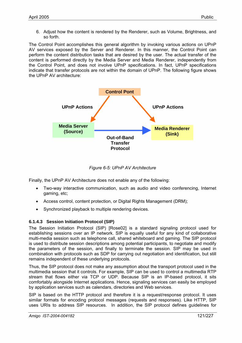
April 2005 Public
6. Adjust how the content is rendered by the Renderer, such as Volume, Brightness, and so forth.
The Control Point accomplishes this general algorithm by invoking various actions on UPnP AV services exposed by the Server and Renderer. In this manner, the Control Point can perform the content distribution tasks that are desired by the user. The actual transfer of the content is performed directly by the Media Server and Media Renderer, independently from the Control Point, and does not involve UPnP specifications. In fact, UPnP specifications indicate that transfer protocols are not within the domain of UPnP. The following figure shows the UPnP AV architecture:
Control Pont
Media Renderer (Sink)
Media Server (Source)
UPnP Actions UPnP Actions
Out-of-Band
Figure 6-5: UPnP AV Architecture
Finally, the UPnP AV Architecture does not enable any of the following:
• Two-way interactive communication, such as audio and video conferencing, Internet gaming, etc;
• Access control, content protection, or Digital Rights Management (DRM);
• Synchronized playback to multiple rendering devices.
6.1.4.3 Session Initiation Protocol (SIP) The Session Initiation Protocol (SIP) [Rose02] is a standard signaling protocol used for establishing sessions over an IP network. SIP is equally
Transfer Protocol
useful for any kind of collaborative
HTTP, SIP uses URIs to address SIP resources. In addition, the SIP protocol defines guidelines for
multi-media session such as telephone call, shared whiteboard and gaming. The SIP protocol is used to distribute session descriptions among potential participants, to negotiate and modify the parameters of the session, and finally to terminate the session. SIP may be used in combination with protocols such as SDP for carrying out negotiation and identification, but still remains independent of these underlying protocols.
Thus, the SIP protocol does not make any assumption about the transport protocol used in the multimedia session that it controls. For example, SIP can be used to control a multimedia RTP stream that flows either via TCP or UDP. Because SIP is an IP-based protocol, it sits comfortably alongside Internet applications. Hence, signaling services can easily be employed by application services such as calendars, directories and Web services.
SIP is based on the HTTP protocol and therefore it is a request/response protocol. It uses similar formats for encoding protocol messages (requests and responses). Like
Amigo IST-2004-004182 121/227
April 2005 Public
defining extensions. Extensions may introduce new requests/responses or new fields in the messages carried by SIP. Examples of common SIP extension include SIMPLE for instant messaging and presence. Clients like Microsoft Messenger (v7.0) use SIP as the underlying protocol for presence and messaging.
The basic SIP commands are:
• INVITE Invite users to participate in a session.
• CANCEL Cancel pending transactions.
• ACK Acknowledge the reception of final response to an INVITE request.
• BYE Abandon a session.
ver about its capabilities, including which methods and
isolated stream (Section 6.2.2) and
rom the new – QoS-aware – DLNA Guidelines, which will be released in ed (Section 6.2.5).
characteristics of those perturbations. High frequency changes, such as interference, are often of such a short duration that it is not possible t react in a timely manner; thus, a preventive measure has to be taken. Typically this results in open-loop control systems, and associated actions are often taken at a low level (e.g., in or close to the hardware), generally based on coarse differentiation mechanism evel. On the other hand, less frequent changes, such as the introduction of a new stream can, and should, be dealt with in a
• OPTIONS Query a serwhich session description protocols it supports.
• REGISTER Tell a server to register the current location of a user.
6.2 Quality of Service in the CE domain Future home networks, as in particular investigated in Amigo, are assumed to connect mobile, PC and CE devices. PCs use the network in a best effort way to guarantee a high mean throughput. On the other hand, CE devices deliver and consume high quality video streams that imply strict timing requirements on the transport of packets. Mobile devices are per definition connected to wireless networks. Their introduction into the home requires a wireless home network part. Unfortunately, the wireless networks by their nature are not suited for uninterrupted video streaming.
We observe that the current line of thinking over wireless video streaming is very much influenced by the Internet model of best-effort streaming with adaptive applications to show a poor picture rather than having to wait. In the following sections, we set out how to manage multiple high quality video streams through the home network. At this moment it is unclear which parts of the network will be wired and which part wireless, thus, we discuss some network topology possibilities.
In the following sections, we discuss the QoS problem in multimedia streaming in the home network (Section 6.2.1), further analyzing the cases of an of medium sharing between streams (Section 6.2.3). The need for a QoS-aware middleware to support network management for QoS assurance is discussed in Section 6.2.4. We propose a base solution to the QoS problem in multimedia streaming within Amigo, drawing from information extracted fmid-2005. This solution is mostly UPnP-QoS-bas
6.2.1 Problem analysis Any stream in a (wireless) network is subject to external factors that may negatively impact the resulting video quality. It is necessary to appropriately address these issues, while at the same time meeting deadlines to assure rendering without delays. Typical causes leading to varying circumstances are (1) interference, (2) a device fluctuating between being in- and out-of-range, (3) new streams entering the network, and (4) handovers. A management and control model that deals with these kinds of problems will have to be based on the specific
o
s introduced at a higher l
Amigo IST-2004-004182 122/227
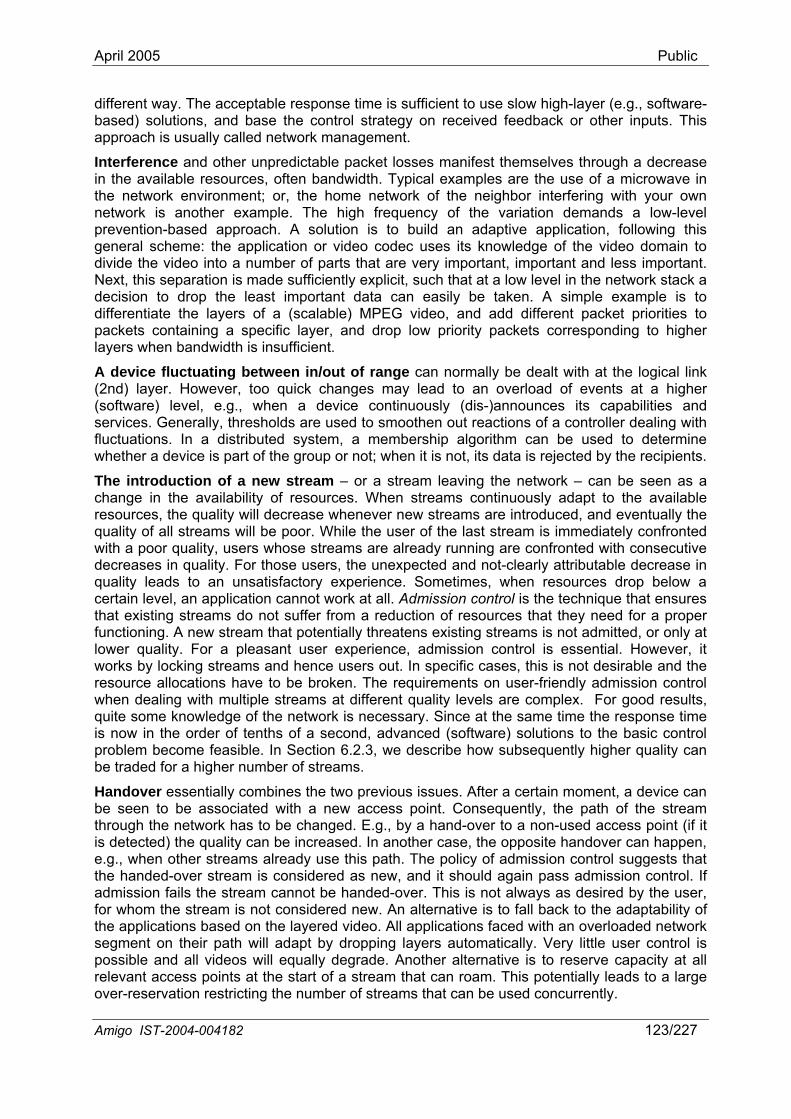
April 2005 Public
different way. The acceptable response time is sufficient to use slow high-layer (e.g., software-based) solutions, and base the control strategy on received feedback or other inputs. This approach is usually called network management.
Interference and other unpredictable packet losses manifest themselves through a decrease in the available resources, often bandwidth. Typical examples are the use of a microwave in the network environment; or, the home network of the neighbor interfering with your own network is another example. The high frequency of the variation demands a low-level prevention-based approach. A solution is to build an adaptive application, following this general scheme: the application or video codec uses its knowledge of the video domain to divide the video into a number of parts that are very important, important and less important. Next, this separation is made sufficiently explicit, such that at a low level in the network stack a decision to drop the least important data can easily be taken. A simple example is to differentiate the layers of a (scalable) MPEG video, and add different packet priorities to packets containing a specific layer, and drop low priority packets corresponding to higher layers when bandwidth is insufficient.
A device fluctuating between in/out of range can normally be dealt with at the logical link (2nd) layer. However, too quick changes may lead to an overload of events at a higher (software) level, e.g., when a de )announces its capabilities and services. Generally, thresholds are a controller dealing with fluctuations. In a distributed system, a membership algorithm can be used to determine
cations have to be broken. The requirements on user-friendly admission control when dealing with multiple streams at different quality levels are complex. For good results, quite some knowledge of the network is necessary. Since at the same time the response time is now in the order of tenths of a second, advanced (software) solutions to the basic control problem become feasible. In Section 6.2.3, we describe how subsequently higher quality can be traded for a higher number of s
user control is possible and all videos will equally degrade. Another alternative is to reserve capacity at all relevant access points at the start of a stream that can roam. This potentially leads to a large over-reservation restricting the number of streams that can be used concurrently.
vice continuously (dis- used to smoothen out reactions of
whether a device is part of the group or not; when it is not, its data is rejected by the recipients.
The introduction of a new stream – or a stream leaving the network – can be seen as a change in the availability of resources. When streams continuously adapt to the available resources, the quality will decrease whenever new streams are introduced, and eventually the quality of all streams will be poor. While the user of the last stream is immediately confronted with a poor quality, users whose streams are already running are confronted with consecutive decreases in quality. For those users, the unexpected and not-clearly attributable decrease in quality leads to an unsatisfactory experience. Sometimes, when resources drop below a certain level, an application cannot work at all. Admission control is the technique that ensures that existing streams do not suffer from a reduction of resources that they need for a proper functioning. A new stream that potentially threatens existing streams is not admitted, or only at lower quality. For a pleasant user experience, admission control is essential. However, it works by locking streams and hence users out. In specific cases, this is not desirable and the resource allo
treams.
Handover essentially combines the two previous issues. After a certain moment, a device can be seen to be associated with a new access point. Consequently, the path of the stream through the network has to be changed. E.g., by a hand-over to a non-used access point (if it is detected) the quality can be increased. In another case, the opposite handover can happen, e.g., when other streams already use this path. The policy of admission control suggests that the handed-over stream is considered as new, and it should again pass admission control. If admission fails the stream cannot be handed-over. This is not always as desired by the user, for whom the stream is not considered new. An alternative is to fall back to the adaptability of the applications based on the layered video. All applications faced with an overloaded network segment on their path will adapt by dropping layers automatically. Very little
Amigo IST-2004-004182 123/227
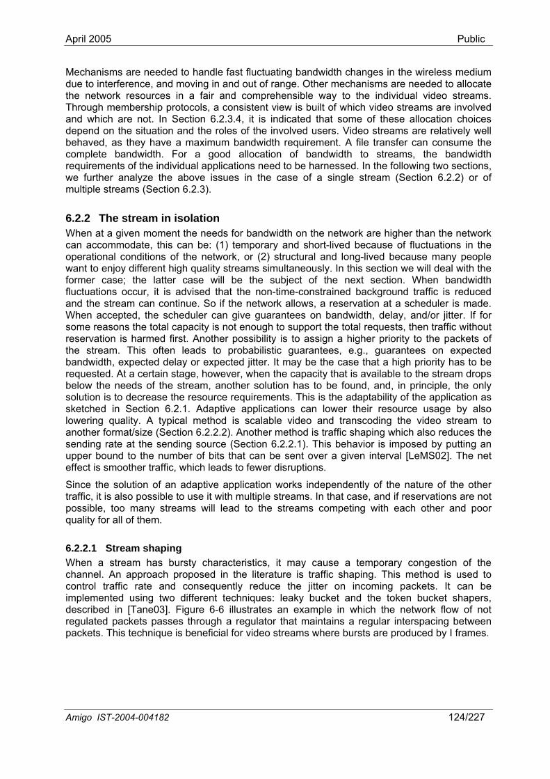
April 2005 Public
Mechanisms are needed to handle fast fluctuating bandwidth changes in the wireless medium
that the non-time-constrained background traffic is reduced and the stream can continue. So if the network allows, a reservation at a scheduler is made.
tees on bandwidth, delay, and/or jitter. If for
e and consequently reduce the jitter on incoming packets. It can be implemented using two different techniques: leaky bucket and the token bucket shapers,
-6 illustrates an example in which the network flow of not
due to interference, and moving in and out of range. Other mechanisms are needed to allocate the network resources in a fair and comprehensible way to the individual video streams. Through membership protocols, a consistent view is built of which video streams are involved and which are not. In Section 6.2.3.4, it is indicated that some of these allocation choices depend on the situation and the roles of the involved users. Video streams are relatively well behaved, as they have a maximum bandwidth requirement. A file transfer can consume the complete bandwidth. For a good allocation of bandwidth to streams, the bandwidth requirements of the individual applications need to be harnessed. In the following two sections, we further analyze the above issues in the case of a single stream (Section 6.2.2) or of multiple streams (Section 6.2.3).
6.2.2 The stream in isolation When at a given moment the needs for bandwidth on the network are higher than the network can accommodate, this can be: (1) temporary and short-lived because of fluctuations in the operational conditions of the network, or (2) structural and long-lived because many people want to enjoy different high quality streams simultaneously. In this section we will deal with the former case; the latter case will be the subject of the next section. When bandwidth fluctuations occur, it is advised
When accepted, the scheduler can give guaransome reasons the total capacity is not enough to support the total requests, then traffic without reservation is harmed first. Another possibility is to assign a higher priority to the packets of the stream. This often leads to probabilistic guarantees, e.g., guarantees on expected bandwidth, expected delay or expected jitter. It may be the case that a high priority has to be requested. At a certain stage, however, when the capacity that is available to the stream drops below the needs of the stream, another solution has to be found, and, in principle, the only solution is to decrease the resource requirements. This is the adaptability of the application as sketched in Section 6.2.1. Adaptive applications can lower their resource usage by also lowering quality. A typical method is scalable video and transcoding the video stream to another format/size (Section 6.2.2.2). Another method is traffic shaping which also reduces the sending rate at the sending source (Section 6.2.2.1). This behavior is imposed by putting an upper bound to the number of bits that can be sent over a given interval [LeMS02]. The net effect is smoother traffic, which leads to fewer disruptions.
Since the solution of an adaptive application works independently of the nature of the other traffic, it is also possible to use it with multiple streams. In that case, and if reservations are not possible, too many streams will lead to the streams competing with each other and poor quality for all of them.
6.2.2.1 Stream shaping When a stream has bursty characteristics, it may cause a temporary congestion of the channel. An approach proposed in the literature is traffic shaping. This method is used to control traffic rat
described in [Tane03]. Figure 6regulated packets passes through a regulator that maintains a regular interspacing between packets. This technique is beneficial for video streams where bursts are produced by I frames.
Amigo IST-2004-004182 124/227
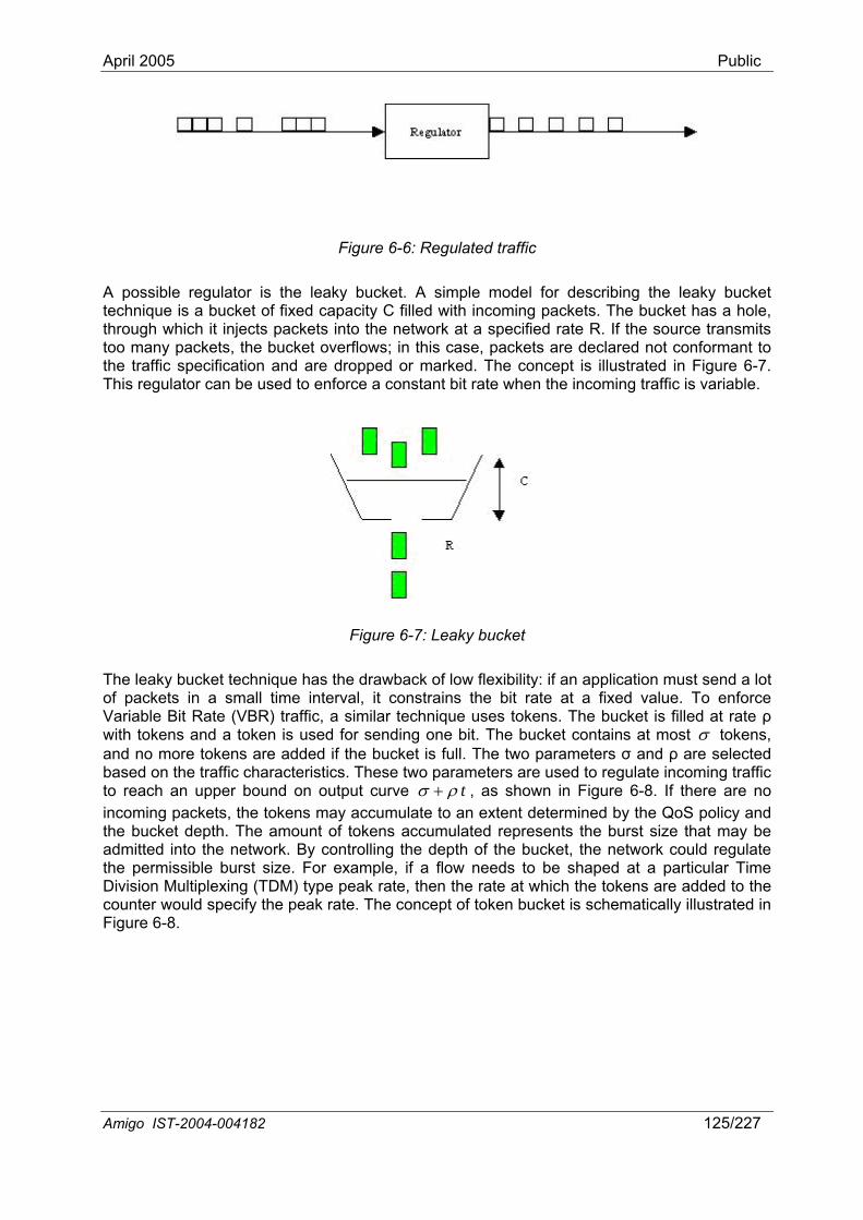
April 2005 Public
Figure 6-6: Regulated traffic
A possible regulator is the leaky bucket. A simple model for describing the leaky bucket technique is a bucket of fixed capacity C filled with incoming packets. The bucket has a hole, through which it injects packets into the network at a specified rate R. If the source transmits too many packets, the bucket overflows; in this case, packets are declared not conformant to the traffic specification and are dropped or marked. The concept is illustrated in Figure 6-7. This regulator can be used to enforce a constant bit rate when the incoming traffic is variable.
Figure 6-7: Leaky bucket
The leaky bucket technique has the drawback of low flexibility: if an application must send a lot of packets in a small time interval, it constrains the bit rate at a fixed value. To enforce Variable Bit Rate (VBR) traffic, a similar technique uses tokens. The bucket is filled at rate ρ with tokens and a token is used for sending one bit. The bucket contains at most σ tokens, and no more tokens are added if the bucket is full. The two parameters σ and ρ are selected bas two parameters are used to regulate incoming traffic to reach an upper bound on output curve
ed on the traffic characteristics. Thesetρσ + , as shown in Figure 6-8. If there are no
inco in accumulate to an extent determined by the QoS policy and the c th. The amount of tokens accumulated represents the burst size that may be
m g packets, the tokens may bu ket dep
admitted into the network. By controlling the depth of the bucket, the network could regulate the permissible burst size. For example, if a flow needs to be shaped at a particular Time Division Multiplexing (TDM) type peak rate, then the rate at which the tokens are added to the counter would specify the peak rate. The concept of token bucket is schematically illustrated in Figure 6-8.
Amigo IST-2004-004182 125/227
April 2005 Public
Figure 6-8: Token bucket
These techniques can be used to reduce the load of the network. Most suggestions in the literature concern the sharing of video with other traffic. The other traffic, e.g., file transfer,
own amount of the bandwidth is on-video traffic. The large difference between a regulator and a reservation
adapt the video code bit rate to the operational conditions on the
dium sharing between streams
f sufficient bandwidth is available on the average, the tight
ynamic network in which devices are involved in sending or receiving a stream
goes through a network regulator, so that only a limited knused by the nmechanism is that the first regulates the bandwidth, and the second reserves a time window. The first will try to send the same number of packets per time unit, independently of the failure rate of the medium. Consequently more time will be spent for the transmission. The second will allow sending of data within a given time slot, and consequently the effective packet rate depends on the failure rate of the medium during the time slot of transmission.
6.2.2.2 Transcoding The increasing number and types of devices and content representations makes the interoperability between devices and networks more important. Gateways are needed to connect networks and devices to each other. Transcoding of video content is a key technology. In the context of this section, transcoding is important to adjust the bandwidth requirements of the stream.
The majority of interest in transcoders focuses on channel capacity availability and conversion between Constant Bit Rate (CBR) and Variable Bit Rate (VBR) streams. A cascaded approach decodes the incoming streams, manipulates the contents and encodes the streams. This is a very costly approach. In this section, we concentrate on MPEG-x transcoding to reduce the bit rate. We assume a high quality MPEG stream coming in and a lower bit rate (scalable) MPEG stream coming out. A typical application for a transcoder is to adapt the video from a high bandwidth medium to a low bandwidth medium. For example, the transcoder is associated with an Access Point towireless link. It dynamically transcodes an MPEG-2 stream (e.g., one coming from a DVD) to a less bandwidth-consuming stream or a scalable stream. Transcoding between MPEG-2 and scalable MPEG-2 can be done in an efficient way [Jarn04]. Together with the possibility to adapt efficiently to the operational conditions, a transcoder can improve the total perceived quality at the rendering display.
6.2.3 MeEnsuring QoS is getting more complex, when requirements of multiple streams have to be satisfied at the same time. Audio/Video streams are expected to generate an important load on the network. There are two obvious cases to distinguish: on the average, sufficient bandwidth is available or not. Even irequirements on jitter and delay may still demand that better guarantees are given to the applications at specific moments. Secondly, when there is a structural and long-lived shortage of bandwidth – because many people want to enjoy different high quality streams simultaneously – the network resource has to be managed to accommodate the users sharing it. In the following sections, we first describe how group membership protocols are used to identify a d
Amigo IST-2004-004182 126/227
April 2005 Public
(Section 6.2.3.1). Next (Sections 6.2.3.2 & 6.2.3.3), we describe how an application would
twork, a view on the connected devices and connected
re started, halted or stopped. In the wire s e and return within range. Decisions in the home net r y the members of a group of devices or applications. Group decisions are required to be consistent, i.e., every member of the group takes the same decision. W es its input to the other members, the associated message may not arrive at all group members. Two possibilities exist: (1) all members decide that the sou member, and those that receive the message ignore it; or (2) all members
on 6.2.2, it was indicated that an application has to acquire network resources to that some communication technologies w the use of a “higher” priority, and yet
deliver quality-of-service (QoS) requests to all nodes
initially request network resources (bandwidth, delay, jitter, etc.) from the network resource manager. This manager can be implemented in a distributed fashion or on one central device. This network resource manager has to evaluate whether such a request can be granted. This requires the network resource manager to have insight in the consequences of assigning time slots, priorities, etc., to applications. Priorities are also addressed. Finally, Section 6.2.3.4 deals with the issue of how to let the users of the network control their network resources. The user requirements occasionally demand more streams than can be handled, or different streams, or streams of different importance, and this may imply that guarantees that were given to applications before have to be withdrawn to accommodate the new situation. Partially, network resource management shall be based on individual user preferences and rely on social structures.
6.2.3.1 Group membership Group membership is an important concept in fault tolerance and decision procedures in general. In the context of the home neapplications (video streams) that is shared by all members helps to solve decision processes [Veri94]. In the home, the network configuration is supposed to be dynamic. Devices are connected, disconnected or switched off. Applications a
le s context, devices get out of rangwo k depend on the input generated b
hen a member distribut
rce is not adecide the source is a member, and members are made aware that they have not received the input, when the message does not arrive.
The group membership assures that at a given moment in time, or with respect to a sequence of input messages, the group membership is defined, and all members of the group know all other members of the group at the specified moment. Solving the group membership allows a consistent decision making within the home network. Several membership algorithms exist. They solve the problem, depending on the fault hypothesis and the time characteristics of the underlying network. Algorithms also differ in the time it takes before a given member knows the membership associated with a decision point. For more information, see [StCA94] or [BLSI03].
6.2.3.2 Reservation / prioritization requests In Sectiensure a high-quality transmission. It was describedoffer the possibility to make reservations, others alloothers offer no mechanisms at all. For example, RSVP is a resource reservation setup protocol designed for quality integrated services on Internet. RSVP is used by a host to request specific qualities of service from the network for particular application data streams or flows. RSVP is also used by routers to along the path(s) of the flows, and to establish and maintain state to provide the requested service. RSVP requests will generally result in resources being reserved in each node along the data path. Nevertheless, as it turns out, network priorities have different semantics across different communication standards, and also reservations are required in different terms. For a programmer of an application that runs in such a heterogeneous network environment it is necessary that a more uniform mechanism is available.
The continuous spectrum of bit rates makes it often more convenient to reduce the quality choices to a small discrete set of values. A good approach is to use a model of layers. It is
Amigo IST-2004-004182 127/227
April 2005 Public
assumed that the bandwidth needs are expressed in the number of layers that are required. This approach does not preclude the storage of content in files with different quality levels. Thus, every video source has a number of quality attributes. These attributes are:
• layers and their bandwidth needs
• quality class of the source
• quality
The quality class of the source, different from the priority class of the packet, indicates the minimum tolerable quality of the associated video. Its value depends on the quality of the screen and the size of the window in which the video is displayed. The quality attribute defines the current operational quality of the video. The latter can be expressed in the number of active layers from the total available layer set.
6.2.3.3 Realization of reservation / prioritization on the network Some communication media deliver possibilities for bandwidth reservation. The prime examples in this section are IEEE 1394, Homeplug 1.0 and IEEE 802.11e. The bandwidth control of IEEE 1394 and Homeplug 1.0 is described in a well-established standard, while the IEEE 802.11e description is, at the time of writing, not yet approved. The alternative method is the use of priorities.
Bandwidth reservation Although, generally, one speaks about bandwidth reservation, the standards (IEEE 1394, IEEE 802.11e) only provide a time-slot in which a sender can transmit without perturbations by other senders. In the case of IEEE 1394, with its low loss probability, the time-slot is almost directly coupled to bandwidth. In the less stable media, this relation is lost. In IEEE 802.11e, the guarantees given are guaranteed transmission opportunities, called TXOPs, rather than guaranteed receptions.
The level to which given guarantees are actually respected very much depends on the employed scheduler. In IEEE 802.11e, this scheduler of the hybrid controller resides in the access point, but is not standardized, and, hence, quality depends very much on the particular implementation. Ethernet, on the contrary, uses merely Carrier Sense Multiple Access / Collision Detection (CSMA/CD). All nodes on the Ethernet wire have a certain probability to successfully send a packet. The success probability goes down with increasing load. With high loads it is possible that no packets are transported at all.
Prioritization What happens when using “higher” priorities is very difficult to predict. If only one stream uses a high priority, one can calculate a guarantee on expected bandwidth, delay or jitter, rather than on the actual ones. But when more streams use this “high” priority, or even “higher” priorities, not much guarantees may be left over. Both IEEE 802.11e and HomePlug 1.0 support priorities. However the different implementations lead to very different behavior over the network. Other network standards may use different implementations again. A few implementation choices are discussed here.
A common approach is to assign a priority to a message. Allocating the medium to the highest priority message is done in HomePlug 1.0. The priority is communicated over the network, so that the device with the highest priority message gets access to the network. This leads to overhead, because the devices need some time before the medium can be allocated to the message with the highest priority. A problem occurs when devices simultaneously decide to send a message with the same priority. The devices will notice the collision and start up a back-off protocol. According to a back-off protocol, each device involved in the collision selects a random time to start its transmission. The device that chooses the shortest back-off interval wins and gains control to the device. Differences occur in the choice of the back-off interval. A
Amigo IST-2004-004182 128/227
April 2005 Public
device first chooses an interval maximum. After every collision, a new larger maximum is selected. The actual back-off interval can be randomly chosen from a range from zero to the interval maximum, or from an interval with a range from the former interval maximum to the new interval maximum.
Another method is to increase the probability of allocation to the medium with increasing priority. To send a message with a given priority, a random back-off is chosen from the associated priority interval. Again several ways exist to choose this back-off, either by taking it
ended with every
6.2.3.4 Bandwidth negotiations ou do not want. There will be
he user(s).
er in this section. Two types of media are considered: (1) media that support
depends on the quality of the screen and the size of the window in which the video is displayed. The importance shows whether the quality of a given source should be higher or lower with respect to another source. Importance can be derived from the
from the complete interval or to choose it from an interval between the current and the interval of a lower priority. The result is that messages with a given priority have a higher probability to be sent than messages with a lower priority. This protocol is used by EDCF in IEEE 802.11e standard.
The set of devices that try to send a message (of the same priority) is called a collision set. In some protocols, all devices belonging to a collision set must have sent their messages before new messages can be sent. In other protocols the collision set can be extnew possibility to send a message.
From the above discussion it is clear that priorities do not always guarantee that a message with a high priority is sent before a lower priority message. Actually there is a probability that a message with a high priority is sent before a message with a lower priority. The value of the probability depends on the protocol implementations, but, generally speaking, the higher the message priority the higher the probability that it will be sent at the first possible send occasion.
There is nothing as user-unfriendly as a system doing things ysituations where users want something else than what the system provides on general principles. Then, the user would want to override the system’s decisions. These situations require an overall system view which is generally not present in individual applications or devices, but only at the user or when “brought into the system”. Assuming that user wishes can be adequately detected, it is necessary that all devices on the network collaborate or are forced to collaborate, so that the bandwidth resource is allocated as specified by tMultiple users can come to conflicting requirements; conflicts usually have to be solved “out of technical bands”, but via social mechanisms. Collaboration means that the devices express their needs to a bandwidth allocation authority (centralized or distributed), and conform their behavior to this specification. The management and effectuation should be decoupled from the devices that happen to have the resources. Example realizations of bandwidth allocation are discussed latreservation from a central authority (e.g., IEEE 802.11), and (2) media that do not support reservation (e.g., switched Ethernet).
The above also implies that user information has to be captured. We extend a little bit our model introduced in Section 6.2.3.2. A node can contain a set of video sources. Every video source has a number of attributes. These attributes are:
• layers and their bandwidth needs
• quality class of the source
• importance
• quality
The quality class of the source can indicate what the minimum tolerable quality is of the associated video. Its value
Amigo IST-2004-004182 129/227
April 2005 Public
social structures in the fam
Amigo IST-2004-004182 130/227
ily. The quality attribute defines the actual quality of the video. The
rid coordinator can issue a so-called imperative request, indicating a change in reservation. This message from the hybrid coordinator enables the
use to the new situation. This could be achieved by
en the transmission conditions change, for example by increasing the distance
n can a user interact with the algorithm directly, before the changes are effectuated. The user can also add more
took the IEEE 802.11e hybrid coordinator as the use it has
the w e of the requests that the other devices in the wireless network make. The hybrid coordinator, however, do nets. In particular, there is no way to make a req sthe wir ted, most home networks will be composed of multiple subnets (wired and wireless). An overall solution requires that the stream requirements can be
latter can be expressed in the number of active layers from the total available layer set. The quality class of the source can be an attribute of the video that is distributed. The latter may even be personalized and depends on the identity of the selecting user. The importance of the video depends on the user’s identity. After addition of a new source, the qualities are recalculated. When the users are unhappy with the new situation, they can adapt the importance or quality class of the source.
We now discuss two example realizations of the bandwidth allocation management introduced above.
Centralized solution (IEEE 802.11e access point) In the following, we describe how a centralized system would handle bandwidth requests and later handle bandwidth negotiations. We first consider an IEEE 802.11e wireless network, where the central authority will be the access point, since it hosts the hybrid coordinator. Later we discuss alternatives and extensions.
The sender of a stream presents its network demands to the hybrid controller, which subsequently checks whether this is possible and then informs the sender that the request is granted. In case of an IEEE 802.11e network, the scheduler is unspecified in the standard and left to the implementer. It has to calculate a new schedule to see whether and how the request can be realized. This is the standard check to perform admission control at the scheduler. Based on the new schedule, the IEEE 802.11e hybrid coordinator starts polling the senders at the appropriate instance specified by the schedule. In certain cases, such as a handover scenario, the circumstances can change, and the scheduler cannot live up to all user desires. It may then calculate an appropriate schedule that can be fulfilled, and inform all involved senders. In IEEE 802.11e, the hyb
senders to adjust their bandwidth diminishing the number of layers for video, or using a tighter bucket for other data streams as described in Section 6.2.2.1. Consequently, through polling, the senders align themselves to the new schedule, and the scheduler imposes the redistribution of the bandwidth. As indicated before, there are many situations where a redistribution of the bandwidth is needed. This could be when a new content is added for distribution over the network, when user requirements change, or whfrom the sender. In Section 6.2.1, we indicated that some devices may continuously enter and leave the network, thereby continuously requesting new bandwidth. A membership protocol can ensure that these devices remain excluded until they are more permanently joining the network.
Even in this centralized solution, a decision should be taken that follows user preferences. It is desirable that the sender/receivers communicate the importance of the streams with respect to other streams for their users, and the importance of the users among each other. Based on these importance descriptions, an appropriate redistribution of the bandwidth can be made, which could follow a proprietary algorithm. An algorithm that can calculate appropriate bandwidth distributions should be in contact with the users. Only the
information to guide the decision.
In the previous part of the discussion, webasis for our centralized solution. The hybrid coordinator makes a good choice, beca
po er to enforce its scheduling decisions on the IEEE 802.11 LAN, and the knowledg
es not extend across multiple subue t for resources for a stream that enters through the access point and is then delivered in
eless LAN. As indica
April 2005 Public
com u that hosts the hybrid coordinator of the
For a network consisting of multiple subnets, it may become necessary to control the resources, not just within the specific subnet, but also collectively over the entire network. To ensure that the user is in control of his/her streaming experience, appropriate deadline partitioning is needed. For this to work, the control needs to be taken from a hybrid coordinator. It has to open up its capabilities so that other devices in the network can ensure end-to-end QoS.
Distributed solution (IEEE 802.3) Consider the switched Ethernet infrastructure. Two phases are considered: a first phase, in which sources are added until the bandwidth is fully consumed, followed by a second phase, where bandwidth of running streams can be reduced to accommodate the new stream. We assume that there is no central authority in the switched Ethernet network, and we investigate a distributed solution. A distributed solution implies that all nodes on the network must know the load created by each connected node. The state of the network is given by the states of the nodes at a given time. The state of a node is defined by the video sources and the bandwidth required by each source. The bandwidth requirement of a video stream can be expressed in th res the states of all connected nodes,node enters the network, the other nodes should communicate their bandwidth consumption to
tual network state number.
emit. This means that every source has
layers, from CE-industry, IT-
m nicated to more devices than just the device local subnet. It also requires that other (authorized) devices instruct schedulers, such as the one of the IEEE 802.11e hybrid coordinator, to perform scheduling which matches the overall requirements and not just the local requirements. The concept of an overall central controller can be introduced. It will have the possibility to optimize across all subnets, leading to potentially much better resource utilizations. Depending on the network and the availability of broadcast mechanisms, centralization may require the transmission of more messages than a distributed approach, as the results have to be sent back to the devices. Also, a central server is a single point of failure and it may be necessary to select a backup.
e number of transmitted layers. We assume that every node sto called the view. Assume that a broadcast facility exists. Every time a
this node. Every time a node wants to add a source with a given bandwidth requirement, it calculates the feasibility from its view. If the source can be added, the node broadcasts its new state to all nodes. If not enough bandwidth is available, then the impossibility is signaled to the requesting source.
When two sources simultaneously broadcast their sending intent, the conflict needs to be solved. A standard procedure is to use an ordered broadcast. All messages arrive in the same order at all nodes. The broadcast of the first source is validated, and the second one is rejected. To verify whether two messages conflict, it is necessary to enumerate the network states and specify the new node state with respect to the acConflicting messages contain a change request with respect to the same state number. A message that concerns an earlier state than the actual one can be rejected.
Consider now the second phase, in which bandwidth requirements of the running streams need to be reduced to accommodate the new stream. To realize the redistribution, one or more sources need to adapt the number of layers they to come to the same conclusion on the new desirable network state. This is a well-known problem in distributed systems: a group of network nodes coming to a consistent decision. A possible solution to the problem is to have the same decision algorithm executing at every node. Every node has the same view on the system state and knows the new request. Having the same input (the system state) and using the same bandwidth reallocation algorithm, every node comes to the same allocation result, and collaborates to realize this new allocation.
6.2.4 QoS-interoperability aspects at the middleware The need of a network-management control model to support high-quality streaming while leaving the user in control requires communication between different devices. We have indicated that the home network is a market where many p
Amigo IST-2004-004182 131/227
April 2005 Public
industry, domotics, as well as mobile meet. This means that we need an interoperable middleware to support a potentially proprietary solution for network management.
One of the first questions is on the location of control. The world has not settled on the question whether there will be a central authority that coordinates the entire home network, however, if such an authority shows up, it is likely to be a PC or an Internet gateway. It is therefore necessary to support the possibility of a distributed solution, wherever possible, to prevent dependence on a single point of failure. This requires support from a sufficiently rich middleware.
A key question is whether control of the QoS is restricteor whether control can be taken by an independent Qo
d to the server and rendering devices,
o QoS. These can be a device’s memory limitations, which pose a jitter bound, but there are also the capabilities of differentiating and
have error correction cap i possible schedulers that can be vices and network segments, if we want to allow dec o routers. Also, certa tabilized, have to be delivered to allow higher-layers to appropriately deal with them or at least inform the user that something is about to happen. ve to be abstracted to present useful concepts to the en
6.2.5 DLNA and Qe previous sections of the QoS problem in multimedia home this section a base solution to this problem for the Amigo
environment. The current forum to make agreements on interoperability for the home network is the DLN NA, guidelines on the use of existing standards possibilities. For instance, in its first guidelines mmittee), the renderer is also the control point, whereas in the underlying UPnP-AV standard, these are different entities and potentially diff n NA currently does not address QoS, there have been proposals for setting d in Sections 6to the end poi e further aims at defining device descriptions for o At the time of writing, the working committee targets towards an early take off via and wireless Ethernet acapabilities of ized QoS is foreseen.
this second phase, reservations and admission control are added to the standard. In the UPnP-AV system, surveyed in Section 6.1.4.2, the UPnP forum has ork for implementing QoS using UPnP-AV components, named UPnP-QoS.
It is expected that DLNA will base their QoS solution on UPnP-QoS. UPnP-QoS is described in the folloassociated UP Then in Section 6.2.5.5, we prese t the DLNA proposal for DLNA works and app a ctions are based on information extracted from new DLNA Guidelines, which will b
6.2. .1 n Various ap abilities on the network, such as whether a media server and/or an intermediate network switch supports packet tagging, or whether a particular wireless link has available capacity to support a media streaming session. Moreover,
S control point. For independent QoS control, a middleware standard should support interoperable descriptions of the capabilities of devices with respect trequirements onprioritizing parts of the content, in order to do packetization or to
ab lities. A control point, furthermore, has to be aware of theemployed and the current load of deisi ns to be taken elsewhere or collectively, rather than only in access points or
in low-level events such as hand-over, when s
Clearly the items indicated here had-user.
oS Based on our analysis in thnetworking, we propose in
A, which we surveyed in Section 6.1.1. In DLimprove interoperability by limiting the(released by the DLNA HNv1 subco
ere t devices. Although DL up QoS through extension headers of HTTP and RTSP, which we surveye.1.3.2 and 6.1.4.1, respectively. However, such an approach limits the QoS control
nts. The DLNA working committeQ S capabilities.
a phased approach. In the first phase, only single subnets of wiredre taken into account, using only priority-based forwarding. For this, no real QoS
devices need to be exposed. For a later phase, parameterInaccordance with defined a framew
wing Sections 6.2.5.1 to 6.2.5.4, which present the UPnP-QoS framework and the nP-QoS components. n
QoS traffic types, enabling uniform prioritization of traffic for diverse netlic tions. These se
e released in mid-2005.
5 U uctioPnP-QoS introdplications may need to detect QoS cap
Amigo IST-2004-004182 132/227
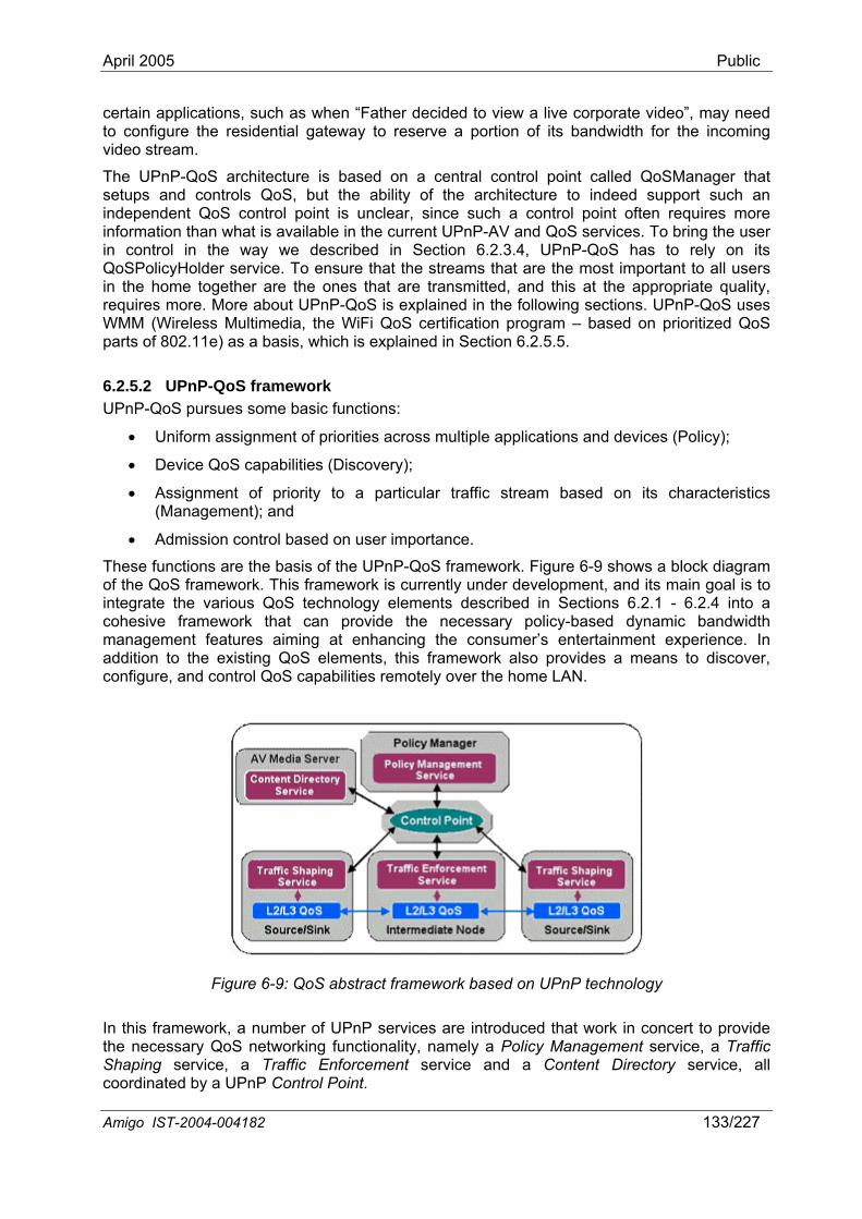
April 2005 Public
certain a y need to configure the residential gateway to reserve a portion of its bandwidth for the incoming
The tral control point called QoSManager that set s architecture to indeed support such an ind e int often requires more informationin control Qo o that the streams that are the most important to all users in t requires mWMM (Wir ogram – based on prioritized QoS par o .2.5.5.
ic functions:
s and devices (Policy);
• of priority to a particular traffic stream based on its characteristics
.
gy elements described in Sections 6.2.1 - 6.2.4 into a
pplications, such as when “Father decided to view a live corporate video”, ma
video stream.
UPnP-QoS architecture is based on a cenility of theup and controls QoS, but the ab
ep ndent QoS control point is unclear, since such a control po than what is available in the current UPnP-AV and QoS services. To bring the user in the way we described in Section 6.2.3.4, UPnP-QoS has to rely on its
SP licyHolder service. To ensure he home together are the ones that are transmitted, and this at the appropriate quality,
ore. More about UPnP-QoS is explained in the following sections. UPnP-QoS uses eless Multimedia, the WiFi QoS certification pr
is, which is explained in Section 6ts f 802.11e) as a bas
6.2.5.2 UPnP-QoS framework UPnP-QoS pursues some bas
• Uniform assignment of priorities across multiple application
• Device QoS capabilities (Discovery);
Assignment (Management); and
• Admission control based on user importance
These functions are the basis of the UPnP-QoS framework. Figure 6-9 shows a block diagram of the QoS framework. This framework is currently under development, and its main goal is to integrate the various QoS technolocohesive framework that can provide the necessary policy-based dynamic bandwidth management features aiming at enhancing the consumer’s entertainment experience. In addition to the existing QoS elements, this framework also provides a means to discover, configure, and control QoS capabilities remotely over the home LAN.
Figure 6-9: QoS abstract framework based on UPnP technology
In this framework, a number of UPnP services are introduced that work in concert to provide the necessary QoS networking functionality, namely a Policy Management service, a Traffic Shaping service, a Traffic Enforcement service and a Content Directory service, all coordinated by a UPnP Control Point.
Amigo IST-2004-004182 133/227
April 2005 Public
The main role of the UPnP Traffic Shaping service is to enumerate the traffic control capabilities on end-systems (PCs and CE devices), expose them to the rest of the UPnP network, and allow control points to configure and control these QoS capabilities remotely. In other words, this service provides a UPnP-based interface to access its traffic control functions, such as packet classification, tagging, and scheduling.
Similarly to the UPnP Traffic Shaping service, the UPnP Traffic Enforcement service provides
he traffic enforcement device.
The PServerrela Manager, such as when a new policy comes ingen ainfo a
The UPmedia conadd control
The Pregular functionality that it has on the UPnP network, such as discovery of devices and ser eFor exthe con management service, obtain a policy decision and a priority setting from the policy manager, and then send a command to the traffic shaping service on the media server to instruct it to tag and shape the packets according to the decision originating from the policy manager.
6.2.5.3 Description of the UPnP-QoS components This section describes the typical UPnP-QoS components and their supported functionalities, which are listed below:
Control Point: - Decides content to be streamed or data to be prioritized - Invokes the QoS Manager service - Acquires
o Traffic Type (AV, Gaming, Voice, Bulk, etc.) o TrafficID from source and sink devices
Destination IP address and port Source IP address and port Optional T-SPEC (contains link management configuration, like
requested bandwidth, minimum and maximum LSP packet size) from UPnP™ AV CDS service
QoS Policy Holder se- Policy
f network resources
an UPnP-based interface to access the underlying traffic enforcement (policing) capabilities. The Traffic Enforcement service is designed to allow applications to request network resources. It also allows a policy management application to enforce a particular policy, by pushing rules down to t
U nP Policy Management service is responsible for exposing the capabilities of the Policy to the rest of the UPnP network, and as such, it listens to UPnP policy requests and
ys them to the actual Policy Manager Application. When a change occurs at the Policy to effect, the Policy Management service may
er te an event that triggers other devices and control points to retrieve the new policy tion. rm
nP AV Content Directory service enumerates content available through the associated server device. In addition to the traditional information stored in accordance with each
tent item, the QoS framework defines further QoS-related metadata extensions to be ed for each item, such as the bit rate, packet size, and so forth. These extensions allow a
point to identify the QoS requirements for each stream.
U nP Control Point plays a pivotal role in the overall QoS framework. In addition to the
vic s, the control point in the QoS framework acts as a relay between the services defined. ample, the control point may obtain QoS requirements for a specific content item from tent directory, use the obtained information to send a resource request to the policy
rvice:
o Controls allocation oo Influences setting of packet priorities o Controls admission of streams
- Holds the user policy
Amigo IST-2004-004182 134/227
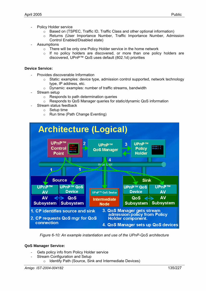
April 2005 Public
- Policy Holder service o Based on (TSPEC, Traffic ID, Traffic Class and other optional information) o Returns (User Importance Number, Traffic Importance Number, Admission
Control Enabled/Disabled state) - Assumptions
o There will be only one Policy Holder service in the home network o If no policy holders are discovered, or more than one policy holders are
discovered, UPnP™ QoS uses default (802.1d) priorities
Device Service: - Provides discoverable Information
o Static: examples: device type ol supported, network technology type, IP address, etc.
o Dynamic: exam width - Stream setup
o Responds to path determination queries o Responds to QoS Manager queries for static/dynamic QoS information
- Stream status feedback o Setup time o Run time (Path Change Eventing)
, admission contr
ples: number of traffic streams, band
Figure 6-10: An example instantiation and use of the UPnP-QoS architecture
d Intermediate Devices)
QoS Manager Service: - Gets policy info from Policy Holder service - Stream Configuration and Setup
o Identify Path (Source, Sink an
Amigo IST-2004-004182 135/227
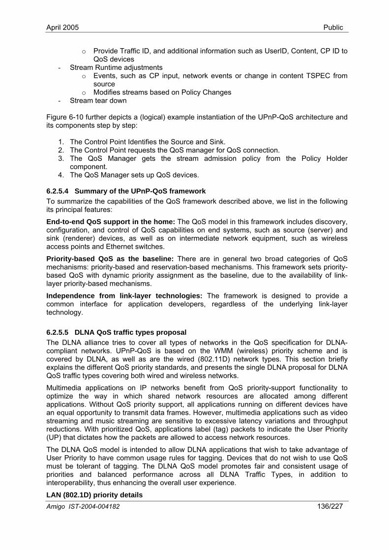
April 2005 Public
o Provide Traffic ID, and additional information such as UserID, Content, CP ID to
- Sto Events, such as CP input, network events nt TSPEC from
source s st a es
- Stream tear down Figure 6-10 further depict ple instantiation of the UPnP-QoS architecture and its components step by step:
1. The Control Point Identifies the Source and Sink. 2. The Control Point requests the QoS manager for QoS connection. 3. The QoS Manag am admission policy from the Policy Holder
co4. The QoS Manager se
6.2.5.4 Summary of the UPnP-QoS framework To summ ab e ork describe above, list following its principal f
End-to-end QoS su includes discovery, configuration, and control of QoS capabilities on end systems, such as source (server) and sink (renderer) devices, as well as on intermediate network equipment, such as wireless
underlying link-layer
QoS priority-support functionality to
LAN (802.1D) priority details
QoS deviceream Runtime a
s djustments
or change in conte
o Modifie re ms based on Policy Chang
s a (logical) exam
er gets the stremponent.
ts up QoS devices.
arize the capeatures:
iliti s of the QoS framew d we in the
pport in the home: The QoS model in this framework
access points and Ethernet switches.
Priority-based QoS as the baseline: There are in general two broad categories of QoS mechanisms: priority-based and reservation-based mechanisms. This framework sets priority-based QoS with dynamic priority assignment as the baseline, due to the availability of link-layer priority-based mechanisms.
Independence from link-layer technologies: The framework is designed to provide a common interface for application developers, regardless of thetechnology.
6.2.5.5 DLNA QoS traffic types proposal The DLNA alliance tries to cover all types of networks in the QoS specification for DLNA-compliant networks. UPnP-QoS is based on the WMM (wireless) priority scheme and is covered by DLNA, as well as are the wired (802.11D) network types. This section briefly explains the different QoS priority standards, and presents the single DLNA proposal for DLNA QoS traffic types covering both wired and wireless networks.
Multimedia applications on IP networks benefit from optimize the way in which shared network resources are allocated among different applications. Without QoS priority support, all applications running on different devices have an equal opportunity to transmit data frames. However, multimedia applications such as video streaming and music streaming are sensitive to excessive latency variations and throughput reductions. With prioritized QoS, applications label (tag) packets to indicate the User Priority (UP) that dictates how the packets are allowed to access network resources.
The DLNA QoS model is intended to allow DLNA applications that wish to take advantage of User Priority to have common usage rules for tagging. Devices that do not wish to use QoS must be tolerant of tagging. The DLNA QoS model promotes fair and consistent usage of priorities and balanced performance across all DLNA Traffic Types, in addition to interoperability, thus enhancing the overall user experience.
Amigo IST-2004-004182 136/227
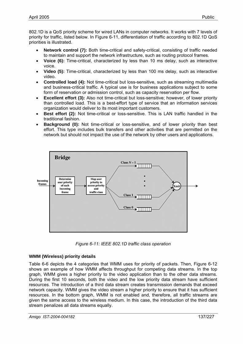
April 2005 Public
802.1D is a QoS priority scheme for wired LANs in computer networks. It works with 7 levels of riority for traffic, listed below. In Figure 6-11, differentiation of traffic according to 802.1D QoS riorities is illustrated.
• Network h time-critical and safety-critical, consisting o traffic needed to maintain and supp outing prot ol frames.
• Voice (6): Time-critical, characterized by less than 10 ms delay, such as interactive
ms delay, such as interactive
• -critical but loss h as streaming multimedia
• not time-critical but loss-sensitive; however, of lower priority services
pp
control (7): Bot focort the network infrastructure, such as r
voice. • Video (5): Time-critical, characterized by less than 00 1
video. Controlled load (4): Not time
iness-critical traffic. A
t effort (3): Also
-sensitive, sucor business apand bus typical use is f plications bject to some
form of reservation or admission control, such as capacity reservation per flow. Excellen
su
rmathan controlled load. This is a best-effort type of service that an info tion organization would deliver to its most important customers.
• Best effort (2): Not time-critical or loss-sensitive. This is LAN traffic handled in the traditional fashion.
• Background (0): Not time-critical or los ower priority than best effort. Th bulk transfers and other activities that are permitted on the
s-sensitive, and of lis type includes
network but should not impact the use of the network by other users and applications.
Figure 6-11: IEEE 802.1D traffic class operation
WMM (Wireless) priority details Table 6-6 depicts the 4 categories that WMM uses for priority of packets. Then, Figure 6-12 shows an example of how WMM affects throughput for competing data streams. In the top graph, WMM gives a higher priority to the video application than to the other data streams. During the first 10 seconds, both the video and the low priority data stream have sufficient resources. The introduction of a third data stream creates transmission demands that exceed network capacity. WMM gives the video stream a higher priority to ensure that it has sufficient resources. In the bottom graph, WMM is not enabled and, therefore, all traffic streams are given the same access to the wireless medium. In this case, the introduction of the third data stream penalizes all data streams equally.
Amigo IST-2004-004182 137/227
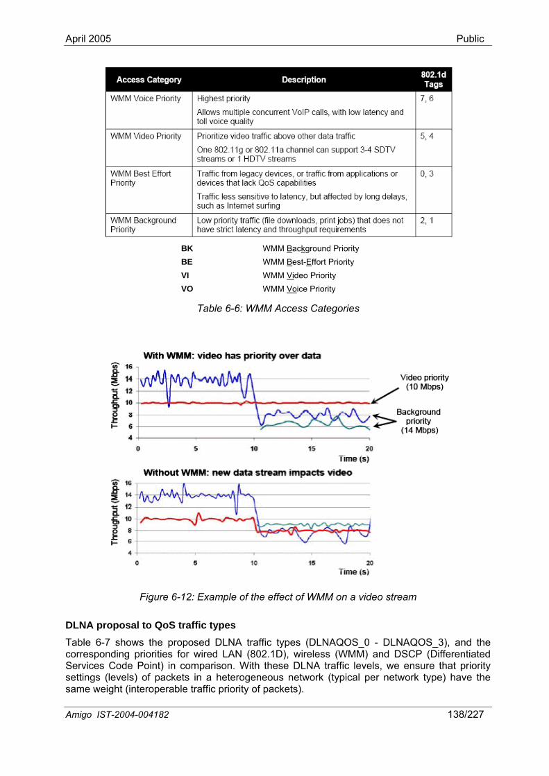
April 2005 Public
BK WMM Backg
WMM Bround
BE Priority
Amigo IST-2004-004182 138/227
est-Effort VI
Priority WMM Video Priority
VO WMM Voice Priority
Table 6-6: WMM Access Categories
Figure 6-12: Example of the effect of WMM on a video stream
DLNA proposal to QoS traffic types Table 6-7 shows the proposed DLNA traffic types (DLNAQOS_0 - DLNAQOS_3), and the corresponding priorities for wired LAN (802.1D), wireless (WMM) and DSCP (Differentiated Services Code Point) in comparison. With these DLNA traffic levels, we ensure that priority settings (levels) of packets in a heterogeneous network (typical per network type) have the same weight (interoperable traffic priority of packets).
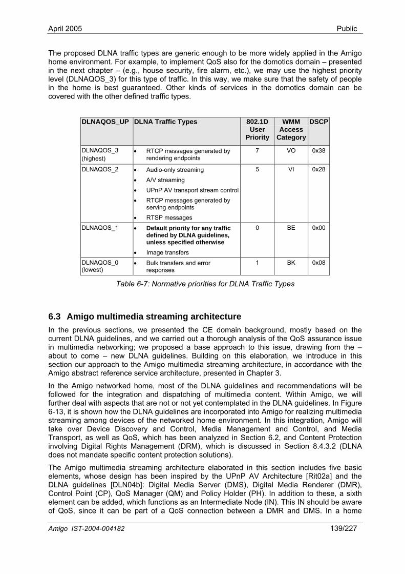
April 2005 Public
A 182 139/227 migo IST-2004-004
ric enough to be more widely applied in the Amigo The proposed DLNA traffic types are genehome environment. For example, to implement QoS also for the domotics domain – presented in the next chapter – (e.g., house security, fire alarm, etc.), we may use the highest priority level (DLNAQOS_3) for this type of traffic. In this way, we make sure that the safety of people in the home is best guaranteed. Other kinds of services in the domotics domain can be covered with the other defined traffic types.
DLNAQOS_UP DLNA Traffic Types 802.1D
User Priority
WMM Access
Category
DSCP
DLNAQOS_3 (highest)
• RTCP messages generated by rendering endpoints
7 VO 0x38
DLNAQOS_2 • Audio-only streaming
• A/V streaming • UPnP AV transport stream control• RTCP messages generated by
serving endpoints
• RTSP messages
5 VI 0x28
DLNAQOS_1 • Default priority for any traffic defined by DLNA guidelines, unless specified otherwise
• Image transfers
0 BE 0x00
DLNAQOS_0 (lowest)
• Bulk transfers and error responses
1 BK 0x08
Table 6-7: Normative priorities for DLNA Traffic Types
6.3 Amigo multimedia streaming architecture In the previous sections, we presented the CE domain background, mostly based on the current DLNA guidelines, and we carried out a thorough analysis of the QoS assurance issue in multimedia networking; we proposed a base approach to this issue, drawing from the – about to come – new DLNA guidelines. Building on this elaboration, we introduce in this section our approach to the Amigo multimedia streaming architecture, in accordance with the Amigo abstract reference service architecture, presented in Chapter 3.
In the Amigo networked home, most of the DLNA guidelines and recommendations will be llowed for the integration and dispatching of multimedia content. Within Amigo, we will rther deal with aspects that are not or not yet contemplated in the DLNA guidelines. In Figure
6-13, it is shown how the DLNA guidelines are incorporated into Amigo for realizing multimedia streaming among devices of the networked home environment. In this integration, will take over d Media
s QoS analyzed in Section 6.2, and Content Protection hts Managem .2 (DLNA
does not mandate specific content protection solutions).
The Amigo multimedia streaming architecture elaborated in this section includes five basic elements, whose design has been inspired by the UPnP hitecture [Rit02a] and the DLNA guidelines [DLN04b]: Digital Media Server (DMS), Digital Media Renderer (DMR), Control Point (CP), QoS Manager (QM) and Policy Holder (PH). In additio sixth element can be added, whic s as a diate Node (IN). This IN aware
be p S co betwe R and DMS. I
fofu
AmigoDevice Discovery and Control, Media Management and Control, an
Transport, as well ainvolving Digital Rig
, which has beenent (DRM), which is discussed in Section 8.4.3
AV Arc
n to these, a should be h function
art of a Qon Intermennectionof QoS, since it can en a DM n a home
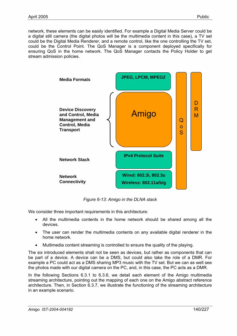
April 2005 Public
network, these elements can be easily identified. For example a Digital Media Server could be a digital still camera (the digital photos will be the multimedia content in this case), a TV set could be the Digital Media trol, like the one controlling the TV set,
l Poi r home netw lder to get
str olicies.
• All the multimedia contents in the home network should be shared among all the devices.
der the multimedia contents on any available digital renderer in the
• Multimedia content streaming is controlled to ensure the quality of the playing.
nts shall not be seen but rather as components that can evice can be a DMS, but could also take the role of a DMR. For
in an example scenario.
Renderer, and a remote connt. The QoS Manager is a component deployed specifically focould be the Contro
ensuring QoS in theeam admission p
ork. The QoS Manager contacts the Policy Ho
Amigo IST-2004-004182 140/227
Figure 6-13: Amigo in the DLNA stack
We consider three important requirements in this architecture:
QoS
DRM
• The user can renhome network.
The six introduced elemebe part of a device. A d
as devices,
example a PC could act as a DMS sharing MP3 music with the TV set. But we can as well see the photos made with our digital camera on the PC, and, in this case, the PC acts as a DMR.
In the following Sections 6.3.1 to 6.3.6, we detail each element of the Amigo multimedia streaming architecture, pointing out the mapping of each one on the Amigo abstract reference architecture. Then, in Section 6.3.7, we illustrate the functioning of the streaming architecture
Wired: 802.3i, 802.3u Wireless: 802.11a/b/g
IPv4 Protocol Suite
Device Discovery and Control
Amigo
JPEG, LPCM, MPEG2Media Formats
, Media Management and Control, Media
port
Network Stack
Network vity
Trans
Connecti
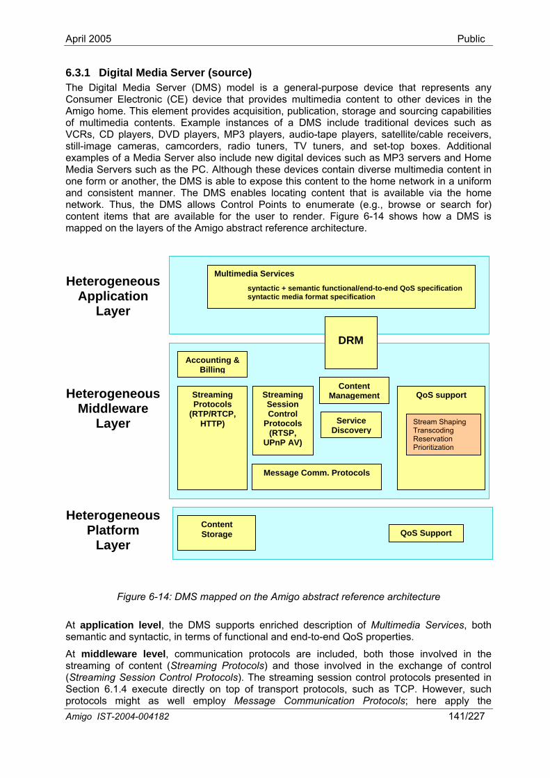
April 2005 Public
6.3.1 Digital Media Server (source)
devices such as MP3 servers and Home edia Servers such as the PC. Although these devices contain diverse multimedia content in ne form or another, the DMS is able to expose this content to the home network in a uniform
an The DMS enables locating content that is available via the home network. Thus, the DMS allows Control Points to enumerate (e.g., browse or search for) conte available for the user to render. Figure 6-14 shows how a DMS is mapped on the layers of the Amigo abstract reference architecture.
At appseman
At str reaming Protocols) and those involved in the exchange of control (St esented in Sec ls, s . However, such protocols as well employ Message Communication Protocols; here apply the
The Digital Media Server (DMS) model is a general-purpose device that represents any Consumer Electronic (CE) device that provides multimedia content to other devices in the Amigo home. This element provides acquisition, publication, storage and sourcing capabilities of multimedia contents. Example instances of a DMS include traditional devices such as VCRs, CD players, DVD players, MP3 players, audio-tape players, satellite/cable receivers, still-image cameras, camcorders, radio tuners, TV tuners, and set-top boxes. Additional examples of a Media Server also include new digitalMo
d consistent manner.
nt items that are
Content Storage
Message Comm. Protocols
Streaming Protocols
(RTP/RTCP, HTTP)
Streaming Session Control
Protocols (RTSP,
UPnP AV)
Service Discovery
Content Management
Accounting & Billing
Multimedia Servicsyntactic +
es s nal/end-to-end QoS specification
syntactic media format specification
Amigo IST-2004-004182 141/227
Figure 6-14: DMS mapped on the Amigo abstract reference architecture
lication level, the DMS supports enriched description of Multimedia Services, both tic and syntactic, in terms of functional and end-to-end QoS properties.
middleware level, communication protocols are included, both those involved in the ng of eami content (St
r
might
eaming Session Control Protocols). The streaming session control protocols prtion 6.1.4 execute directly on top of transport protoco uch as TCP
emantic functio
QoS support
Stream Shaping Transcoding Reservation Prioritization
DRM
QoS Support
He
HeterMiddleware
Layer
HetePlatform
terogeneousApplication
Layer
ogeneous
rogeneous
Layer
April 2005 Public
midmiddleShapin ritization, which were analyzed in Section 6.2. Som essage Communication Protocols. Moreover the middleware layer deals with Service Discovery and Content Management, which enable DMS discovery by users, and handling, locating and listing of multimedia items. Finally, to handle the peculiarities of multimedia content in the sense of copyright and legal protection, enabling paying content and services coming from external service providers, DRM as part of security and privacy, and Accounting & Billing services need to be included in this layer. DRM spans also the application layer.
At platform level, the DMS shall include Content Storage services supporting special features of collecting high amounts of data, which is a common issue when storing A/V contents. In addition, QoS Support aspects at network level are also included here.
6.3.2 Digital Media Renderer (sink) The Digital Media Renderer (DMR) model defines a general-purpose device that represents any Consumer Electronic (CE) device that is capable of rendering AV content from the home network. It exposes a set of rendering controls with which a Control Point (CP) (presented in the next section) can control how the specified AV content is rendered (e.g., Brightness, Contrast, Volume, Mute, etc.). The Digital Media Renderer (DMR) is used to render (e.g., display and/or listen to) content obtained from the home network. Additionally, depending on the transfer protocol that is being used to obtain the content from the network, the DMR may also allow the user to control the flow of the content (e.g., Stop, Pause, Seek, etc). Example instances of a DMR include traditional devices such as TVs, stereo systems and speakers. Some more contemporary examples include digital devices such as MP3 players and Electronic Picture Frames (EPF). Although most of these devices typically render one specific type of content (e.g., a TV typically renders video content), a DMR is able to support a number of different data formats and transfer protocols. For example, a sophisticated implementation of a TV DMR could also support MP3 data, so that its speakers could be used to play MP3 audio content. Figure 6-15 shows the mapping of a DMR on the Amigo abstract reference architecture. At application level, the DMR supports enriched description of Multimedia Sthe DMS are included. At platfo ork-level QoS Support.
6.3.3 Control Point ) coordinates and manages the operation of the DMS and DMR as
synchronizes the DMS and the DMR. The access to the contents is
ting over
dleware communication protocols discussed in Chapters 2 to 5. On the other hand, the ware layer takes care of QoS support aspects applying mechanisms such as Stream g, Transcoding, Reservation and Prio
e of these mechanisms, if distributed in the home network, may employ M
ervices, same as the DMS. At middleware level, most functional blocks of the same level of rm level, the DMR includes netw
The Control Point (CPdirected by the user (e.g., play, stop, pause), in order to accomplish the desired task (e.g., play my favorite music). Additionally, the CP provides the UI for the user to interact with in order to control the operation of the device(s) (e.g., to select the desired content). Some examples of a CP might include a TV with a traditional remote control or a wireless PDA-like device with a small display. The CP done through this element. It provides to the final user the contents that are available in the DMS and the possible devices to reproduce them. It also controls the flow of the contents, as well as some options of the playing, like brightness, volume, etc. Figure 6-16 shows the mapping of a CP on the Amigo abstract reference architecture.
At application level, the CP does not itself host multimedia services, however, it shall be able to interpret and reason on Multimedia Service Descriptions to manage service discovery and set up. At middleware level, Streaming Session Control Protocols, possibly execuMessage Communication Protocols, control streaming sessions between the DMS and the DMR. Further, Service Discovery and Content Management enable locating appropriate DMS and DMR devices and content. Finally, Accounting and Billing manages charging of external paying services.
Amigo IST-2004-004182 142/227
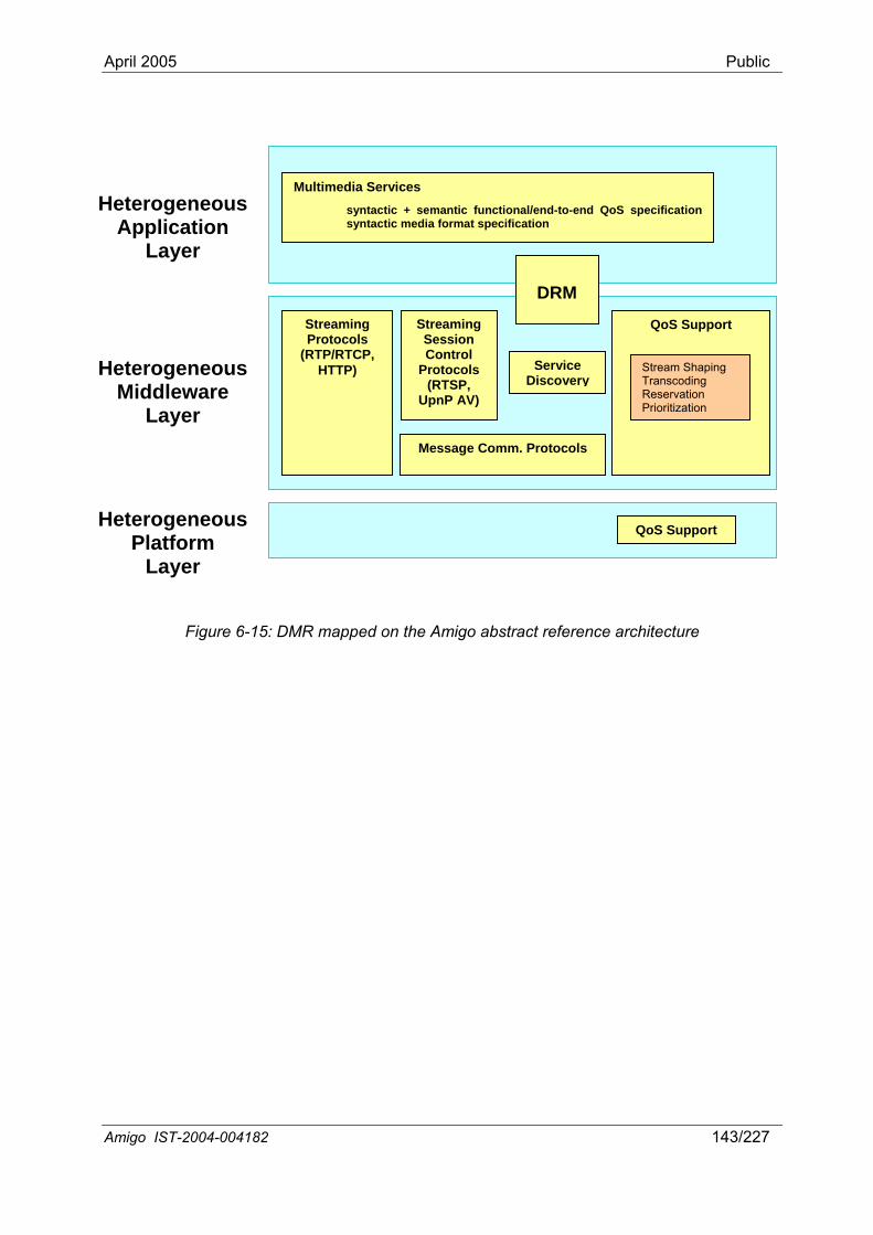
April 2005 Public
Multimedia Servicessyntactic + semantic functional/end-to-end QoS specification syntactic media format specification
Message Comm. Protocols
Streaming Protocols
(RTP/RTCP, HTTP)
Streaming Session Control
Protocols (RTSP,
UpnP AV)
Service Discovery
QoS Support
DRM
QoS Support
Stream Shaping Transcoding Reservation Prioritization
HeterogeneousApplication
Layer
HeterogeneousPlatform
Layer
HeterogeneousMiddleware
Layer
Figure 6-15: DMR mapped on the Amigo abstract reference architecture
Amigo IST-2004-004182 143/227

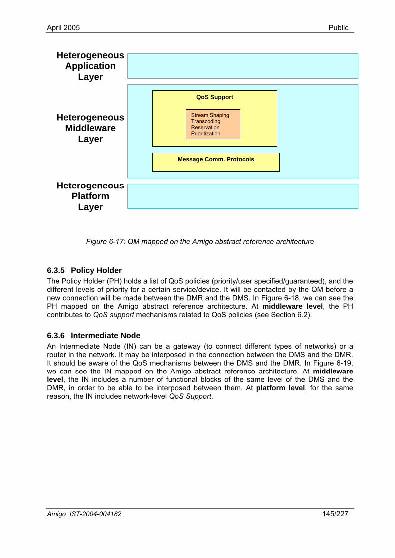
April 2005 Public
Heterogeneous Application
Layer
Message Comm. Protocols
QoS Support
Heterogeneous Middleware
Layer
Heterogeneous Platform
Layer
Stream Shaping Transcoding Reservation Prioritization
on the Amigo abstract reference architecture
6.3The Po /user specified/guaranteed), and the diff nnew oPH macontrib echanisms related to QoS policies (see Section 6.2).
6.3.6 An Interouter in the network. It may be interposed in the connection between the DMS and the DMR.
Figure 6-17: QM mapped
.5 Policy Holder licy Holder (PH) holds a list of QoS policies (priority
ere t levels of priority for a certain service/device. It will be contacted by the QM before a c nnection will be made between the DMR and the DMS. In Figure 6-18, we can see the
pped on the Amigo abstract reference architecture. At middleware level, the PH utes to QoS support m
Intermediate Node rmediate Node (IN) can be a gateway (to connect different types of networks) or a
It should be aware of the QoS mechanisms between the DMS and the DMR. In Figure 6-19, we can see the IN mapped on the Amigo abstract reference architecture. At middleware level, the IN includes a number of functional blocks of the same level of the DMS and the DMR, in order to be able to be interposed between them. At platform level, for the same reason, the IN includes network-level QoS Support.
Amigo IST-2004-004182 145/227
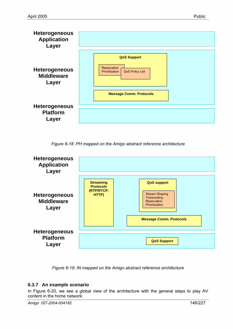
April 2005 Public
Amigo IST-2004-004182 146/227
Figure 6-18: PH mapped on the Amigo abstract reference architecture
6.3.7 An example scenario In Figure 6-20, we see a global view of the architecture with the general steps to play AV
Figure 6-19: IN mapped on the Amigo abstract reference architecture
content in the home network:
Message Comm. Protocols
Layer
Heterogeneous Middleware
Heterogeneous Platform
Layer
Heterogeneous Application
Layer
Streaming Protocols
(RTP/RTCP, HTTP)
QoS support
Stream Shaping Transcoding Reservation Prioritization
QoS Support
Message Comm. Protocols
QoS Support
Heterogeneous pplication
Layer
Heterogeneous Middleware
Layer
Heterogeneous Platform
A
Reservation Prioritization QoS Policy List
Layer
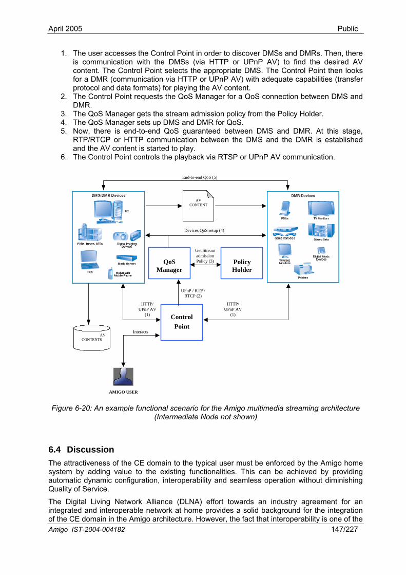
April 2005 Public
1. The user accesses th t in o discover DMSs and DMRs. Then, there is communication with the DMSs (via HTTP or UPnP AV) to find the desired AV content. The Control Point selects the appropriate DMS. The Control Point then looks for a DMR (communication via HTTP or UPnP AV) with adequate capabilities (transfer protocol and data formats) for playing the AV content.
2. The Control Point requests the QoS Manager for a QoS connection between DMS and DMR.
3. The QoS Man y Holder. 4. The QoS Manager sets up DMS and DMR for QoS.
e Control Poin rder to
ager gets the stream admission policy from the Polic
5. Now, there is end-to-end QoS guaranteed between DMS and DMR. At this stage, RTP/RTCP or HTTP communication between the DMS and the DMR is established and the AV content is started to play.
6. The Control Point controls the playback via RTSP or UPnP AV communication.
AVCONTENT
End-to-end QoS (5)
Amigo IST-2004-004182 147/227
ControlPoint
AVCONTENTS
UPnP / RTP /RTCP (2)
HTTP/
AMIGO USER
HTTP/UPnP AV
(1)UPnP AV
(1)
Interacts
QoSManager
Devices QoS setup (4)
PolicyHolder
Get StreamadmissionPolicy (3)
Quality of Service.
The Digital Living Network Alliance (DLNA) effort towards an industry agreement for an able network at home provides a solid background for the integration
o the Amigo architecture. However, the fact that interoperability is one of the
Figure 6-20: An example functional scenario for the Amigo multimedia streaming architecture (Intermediate Node not shown)
6.4 Discussion The attractiveness of the CE domain to the typical user must be enforced by the Amigo home system by adding value to the existing functionalities. This can be achieved by providing automatic dynamic configuration, interoperability and seamless operation without diminishing
integrated and interoperf the CE domain in

April 2005 Public
main objectives of Amigo justifies the acknowledgement, as well, of protocols for multimedia transmission that are well established in the Internet community, such as RTP and RTSP.
d new products are incorporating
ork. The DLNA approach, using UPnP-
service architecture. The Amigo middleware
Thus, the Amigo multimedia streaming architecture shall extend that proposed by the DLNA to assure interoperability and smooth coexistence with other mainstream technologies.
Nevertheless, UPnP is continuously acquiring prestige, annetworking capabilities based on this technology, promoted by the DLNA and the UPnP Forum. UPnP, therefore, stands as the main device discovery and control protocol in the CE domain, and opens the possibility of a straightforward integration into the Amigo architecture. In fact, the, still under development, UPnP-QoS solves much of the problem of QoS integration into such a heterogeneous network as the home netwQoS as a basis, would be a reasonable guideline for the Amigo CE QoS control.
In this chapter, we have elaborated an approach to CE integration in Amigo, building on the above background. The different devices and services involved in this approach have been mapped on the Amigo abstract referencemanages Device Discovery and Control, Media Management and Control, and Media Transport, while QoS functions and DRM span the application, middleware and platform layers.
Amigo IST-2004-004182 148/227
April 2005 Public
7 Integration of the Domotic domain A domotic environment can be defined as a physical space that contains a set of components in housing and society, applicable to safety, security, comfort and self-care. Wherever a domotic system user is, the system should be able to switch the lights on, pull the blinds up, schedule the garden watering, and control any of the white goods in the house. Also,
herefore, several different bus
interfaces to Generally, domotic technologies depend strongly on the manufacturer.
• Different QoS needed: as can be easily observed, controlling a blind or a fire sensor does not need the same QoS: some messages in a domotic network must have higher priority than others, or can have real time requisites; this issue was briefly discussed in Section 6.2.5.5, where the DLNA-proposed priorities for different traffic types were presented.
Currently, there are various bus systems in the domotic area on the market, which allow building up a simple form of an intelligent home. These systems offer different possibilities and, of course, have different shares in the market. The problem of integrating such diverse system components appears to be an enormous task, particularly when seen from each individual manufacturer’s point-of-view, as unique solutions are required for each integration link. Besides these systems, there are a lot of other systems with proprietary protocols. About these systems no general statement is possible. However, at least the integration of the existing bus systems in the Amigo home environment should be possible. To reach this objective, we must especially consider the following aims:
• Integration of existing heterogeneous systems. A new coming up middleware shall be able to integrate the existing systems, and to offer new services upon legacy devices with communication capabilities (actors, sensors, white goods).
ly
activating the anti-thief system or the heating system should be affordable. An alarm should be received and the valves could be locked if a gas or water leak were detected. Refrigerator malfunctions or intruder detections should also be communicated to domotic users, wherever they are. Energy cost savings, security of persons and goods, comfort improvement are some of the benefits of Home Automation. Energy cost savings are achieved thanks to temperature management depending on presence and type of rooms, automatic adaptation of power consumption to tariff rates, or lighting management. Security of persons and goods is increased with functions such as detection of fire or gas leakage, tele-transmission of alarm, or detection of intrusion. Increasing the quality of life brings new facilities for elderly, in-house distribution of entertainment and services, tele-control of heating and lighting. To achieve all these new services, home appliances, connected on different communication media, have to communicate and exchange messages in a structured way. Tsystems connecting home devices have been established in the market. The main features of a domotic device are:
• Simplicity: elemental devices with no complex hardware and with simple communication technologies.
• Low bandwidth requirements: messages in a domotic network are short and not frequent. High bandwidth is not a requisite for domotic systems.
• Small resource capabilities: in general, functionality provided by current domotic devices does not need a big amount of resources.
• Manufacturer dependency: different vendors offer diverse and quite specific each particular device.
• Extensibility to new devices. New systems and devices should be easiincorporated into the home environment by means of an extensible middleware.
Amigo IST-2004-004182 149/227
April 2005 Public
• Easy scenario development and integration. The commissioning and theuration of a networked home currently need to be done by an
config expert. The configuration is hard work, and even experts make mistakes, especially when setting
Since we have to deal with a diverse set of systems and devices, the key to be able to heterogeneous systems is getting a well-known, common interface, so that the
n this
s protocols presenting their
7.1 rotocols The o s systems (BatiBUS, EHS, EIB, KO E ed in the market, and point out the differences and dis-/advantages of these sy
7.1
up scenarios or automatisms. A scenario is a decentralized controlling of more than one device, e.g., switching on two lamps. An ex post configuration, like the changing or adding of a new scenario, done by an ordinary user is unthinkable. Thus, allowing easy scenario development would facilitate enormously the installation of domotic systems.
integrate suchdevices can be addressed independently of the domotic network to which they are connected. This common interface can be any Amigo-supported Service Discovery Protocol (SDP), like UPnP, SLP, Jini, etc., and its associated interaction mechanism. Thus, our objective is flexible, networked domotic services provision in the Amigo home environment. We elaborate ichapter a structured approach towards building discoverable software proxies (UPnP-enabled, Jini-enabled, etc.) of all domotic devices, so that they can be discovered and controlled using the Amigo service discovery and communication, independently of their bus system or configuration.
In the following, we first survey currently established domotic bumain features (Section 7.1). Then, we elaborate the Amigo domotic service architecture, in accordance with the Amigo abstract reference service architecture presented in Chapter 3 (Section 7.2). We finally present our conclusions (Section 7.3).
Background on domotic bus p f llowing sections present the most important bu
NN X, LON, BDF) establishstems.
.1 BatiBUS LANDIS & GYR, MERLIN GERIN, AIRLEC and EDF developed BatiBUS37 . These four firms founded also the BatiBUS Club International (BCI) in 1989 in order to promote the BatiBUS system. Today the BatiBUS association has over 80 partners mainly engaged in the fields of energy control, security, access control, lighting and teleservice.
n
of the
BatiBUS is an open protocol and has been accepted in France as a standard for building control systems. The French standard is described as NFC 46620 and lays down regulations for the physical layer, data link layer, application layer, and network management requirements. The BatiBUS standard is also accepted by the CENELEC (EuropeaElectronics Standard Committee) and ISO (International Standards Organization) initiatives.
A twisted-pair is used for the BatiBUS. It can be laid parallel to the mains power supply network. Any telephone wire pair or twisted electric cable may be used, shielded or not. The Bus Line interconnects all sensors and actuators in a building control system. Doing so 7680 devices can be connected to the bus at one time.
The BatiBUS topology can be implemented in a line, star, tree or loop formation. Table 7-1 shows the maximum lengths applied to the bus given the cross-sectional areaconducting lines. The distance (D) is the maximum distance between the central unit and the farthest point. The length (L) is the total network length.
.net/Batibus.htm 37 http://www.batibus.com, http://www.domotica
Amigo IST-2004-004182 150/227
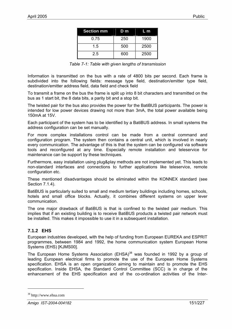
April 2005 Public
Section mm D m L m
0.75 250 1900
1.5 500 2500
2.5 600 2500
Table 7-1: Table with given lengths of transmission
suited to small and medium tertiary buildings including homes, schools, ice blocks. Actually, it combines different systems on upper lever
Information is transmitted on the b with rate of 4800 bits per second. Each frame is subdivided into the follow g fie s: message ype field, destination/em field, destination/emitter addr ield ta f and eck field
To transmit a frame on the bus the frame is split up into 8 bit characters and transmitted on the bus as 1 start bit, the 8 data bits, a parity bit and a stop bit.
The twisted pair for the bus also provides the power for the BatiBUS participants. The power is intended for low power devices drawing not more than 3mA, the total power available being 150mA at 15V.
us ain ld t itter type
ess f , da ield ch
Each participant of the system has to be identified by a BatiBUS address. In small systems the address configuration can be set manually.
For more complex installations control can be made from a central command and configuration program. The system then contains a central unit, which is involved in nearly every communication. The advantage of this is that the system can be configured via software tools and reconfigured at any time. Especially remote installation and teleservice for maintenance can be support by these techniques.
Furthermore, easy installation using plug&play methods are not implemented yet. This leads to non-standard interfaces and connections to further applications like teleservice, remote configuration etc.
These mentioned disadvantages should be eliminated within the KONNEX standard (see Section 7.1.4).
BatiBUS is particularly hotels and small offcommunication.
The one major drawback of BatiBUS is that is confined to the twisted pair medium. This implies that if an existing building is to receive BatiBUS products a twisted pair network must be installed. This makes it impossible to use it in a subsequent installation.
7.1.2 EHS European industries developed, with the help of funding from European EUREKA and ESPRIT programmes, between 1984 and 1992, the home communication system European Home Systems (EHS) [KJMS00].
The European Home Systems Association (EHSA)38 was founded in 1992 by a group of leading European electrical firms to promote the use of the European Home Systems specification. EHSA is an open organization aiming to maintain and to promote the EHS specification. Inside EHSA, the Standard Control Committee (SCC) is in charge of the enhancement of the EHS specification and of the co-ordination activities of the Inter-
38 http://www.ehsa.com
Amigo IST-2004-004182 151/227
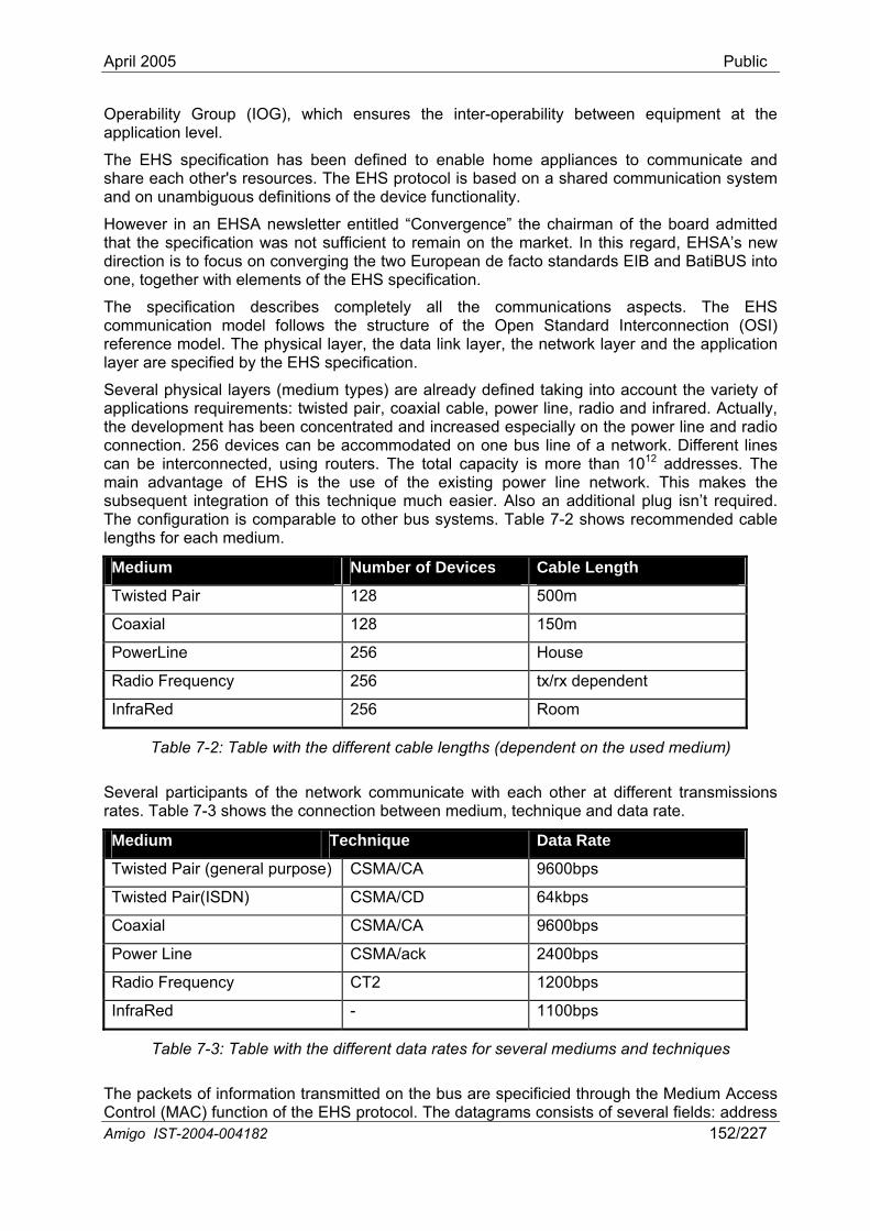
April 2005 Public
Operability Group (IOG), which ensures the inter-operability between equipment at the application level.
The EHS specification has been defined to enable home appliances to communicate and share each other's resources. The EHS protocol is based on a shared communication system and on unambiguous definitions of the device functionality.
However in an EHSA newsletter entitled “Convergence” the chairman of the board admitted that the specification was not sufficient to remain on the market. In this regard, EHSA’s new direction is to focus on converging the two European de facto standards EIB and BatiBUS into one, together with elements of the EHS specification.
The specification describes completely all the communications aspects. The EHS communication model follows the structure of the Open Standard Interconnection (OSI) reference model. The physical layer, the data link layer, the network layer and the application layer are specified by the EHS specification.
Several physical layers (m nto account the variety of applications requirements: twisted pair, coaxial cable, power line, radio and infrared. Actually, the development has been concentrated and increased especially on the power line and radio
on one bus line of a network. Different lines nnected, using routers. The total capacity is more than 1012 addresses. The
edium types) are already defined taking i
connection. 256 devices can be accommodatedcan be intercomain advantage of EHS is the use of the existing power line network. This makes the subsequent integration of this technique much easier. Also an additional plug isn’t required. The configuration is comparable to other bus systems. Table 7-2 shows recommended cable lengths for each medium.
Medium Number of Devices Cable Length Twisted Pair 128 500m Coaxial 128 150m PowerLine 256 House Radio Frequency 256 tx/rx dependent InfraRed 256 Room
Table 7-2: Table with the different cable lengths (dependent on the used medium)
Several participants of the network communicate with each other at different transmissions rates. Table 7-3 shows the connection between medium, technique and data rate.
Medium Technique Data Rate Twisted Pair (general purpose) CSMA/CA 9600bps Twisted Pair(ISDN) CSMA/CD 64kbps Coaxial CSMA/CA 9600bps Power Line CSMA/ack 2400bps Radio Frequency CT2 1200bps InfraRed - 1100bps
Amigo IST-2004-004182 152/227
Table 7-3: Table with the different data rates for several mediums and techniques
tion transmitted on the bus are specificied through the Medium Access Control (MAC) function of the EHS protocol. The datagrams consists of several fields: address The packets of informa
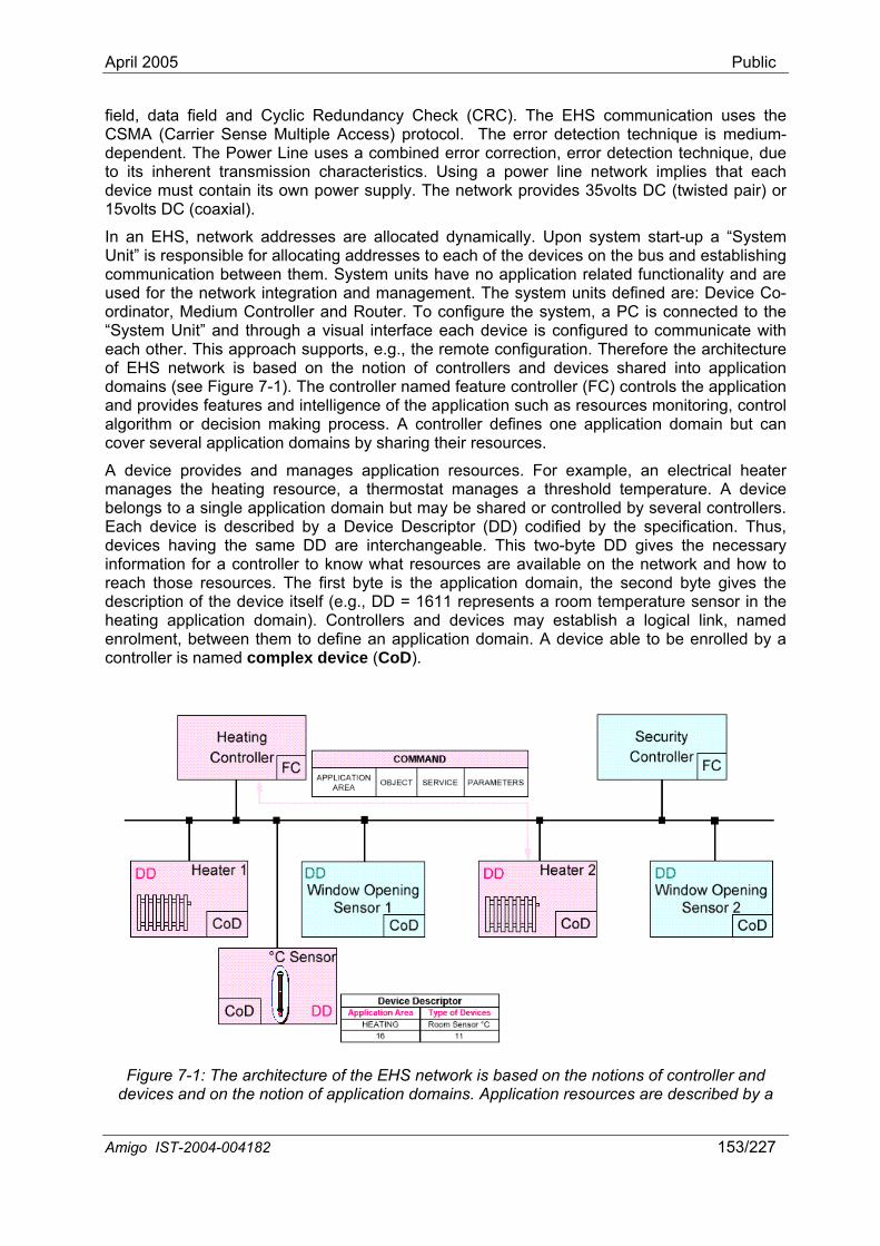
April 2005 Public
field, data field and Cyclic Redundancy Check (CRC). The EHS communication uses the CSMA (Carrier Sense Multiple Access) protocol. The error detection technique is medium-
ependent. The Power Line uses a combined error correction, error detection technique, due its inherent transmission characteristics. Using a power line network implies that each
device must contain its ow ly. The vides 35v (twisted pair) or 15volts DC (coaxial).
In an EHS, network addresses are allocated d n sys tart-up a “System Unit sible for allo ddresses to e devices on s and establishing com between t m units ha lication rela ctionality and are used for the egration an stem units d Device Co-ordinator, Medium Controller and Router. To co system, a connected to the “Sys gh a visual interface ea is configur ommunicate with each is approach , e.g., the re uration. T re the architecture of EHS network is based on the notion of controllers and devices application domains (see Figure 7-1). The controller named feature controller (FC) controls the application and ce of the ap h as reso monitoring, control algorithm or decision making process. A controller defines one application domain but can cover several application domains by sharing their resources.
A device pr ater manages the heating resource, a thermostat manages a threshold temperature. A device
re interchangeable. This two-byte DD gives the necessary inform r lle now resources are available on the network and how to
resources. The first byte is the application domain, the second byte gives the escription of the device itself (e.g., DD = 1611 represents a room temperature sensor in the
dto
n power supp network pro olts DC
ynamically. Upo tem s” is respon cating a ach of the the bumunication
network inthem. Syste
d management. The syve no app ted fun
efined are: nfigure the PC is
tem Unit” and throu ch device ed to c other. Th supports mote config herefo
shared into
provides features and intelligen plication suc urces
ovides and manages application resources. For example, an electrical he
belongs to a single application domain but may be shared or controlled by several controllers. Each device is described by a Device Descriptor (DD) codified by the specification. Thus, devices having the same DD a
ation fo a contro r to k what reach thosedheating application domain). Controllers and devices may establish a logical link, named enrolment, between them to define an application domain. A device able to be enrolled by a controller is named complex device (CoD).
Figure 7-1: The architecture of the EHS network is based on the notions of controller and devices and on the notion of application domains. Application resources are described by a
Amigo IST-2004-004182 153/227
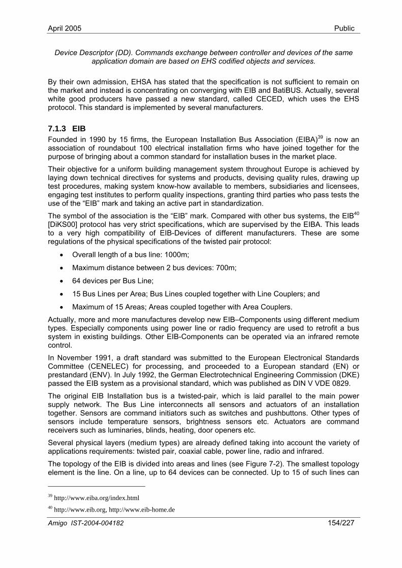
April 2005 Public
Device Descriptor (DD). Commands exchange between controller and devices of the same application domain are based on EHS codified objects and services.
By their own admission, EHSA has stated that the specification is not sufficient to remain on the market and instead is concentrating on converging with EIB and BatiBUS. Actually, several white good producers have passed a new standard, called CECED, which uses the EHS protocol. This standard is implemented by several manufacturers.
7.1.3 EIB Founded in 1990 by 15 firms, the European Installation Bus Association (EIBA)39 is now an association of roundabout 100 electrical installation firms who have joined together for the purpose of bringing about a common standard for installation buses in the market place.
Their objective for a uniform building management system throughout Europe is achieved by laying down technical directives for systems and products, devising quality rules, drawing up test procedures, making system know-how available to members, subsidiaries and licensees, engaging test institutes to perform quality inspections, granting third parties who pass tests the use of the “EIB” mark and taking an active part in standardization.
the association is the “EIB” mark. Compared with other bus systems, the EIB40
• 15 Bus Lines pe L es co with Line Couplers; and
• as; Areas coupled together with Area Couplers.
Actual anufactures develop new EIB–Components using different medium types. Especially components using power line or radio frequency are used to retrofit a bus system in existing buildings. Other EIB-Components can be operated via an infrared remote contro
In Nov a draft standard was submitted to the European Electronical Standards Committee (CENELEC) for processing, and proceeded to a European standard (EN) or presta the German Electrotechnical Engineering Commission (DKE) passe isional standard, which was published as DIN V VDE 0829.
The original EIB Installation bus is a twisted-p main power supply network. The Bus uators of an installation together. Sensors are command initiators such as switches and pushbuttons. Other types of
everal physical layers (medium types) are already defined taking into account the variety of applications requirements: twisted pair, coaxial cable, power line, radio and infrared.
The topolog is divided into areas and Figure 7-2). The smallest topology elemen n a line, up to 64 onnected. Up to 15 of such lines can
The symbol of [DiKS00] protocol has very strict specifications, which are supervised by the EIBA. This leads to a very high compatibility of EIB-Devices of different manufacturers. These are some regulations of the physical specifications of the twisted pair protocol:
• Overall length of a bus line: 1000m;
• Maximum distance between 2 bus devices: 700m;
• 64 devices per Bus Line;
r Area; Bus in upled together
Maximum of 15 Are
ly, more and more m
l.
ember 1991,
ndard (ENV). In July 1992,rovd the EIB system as a p
air, which is laid parallel to the Line interconnects all sensors and act
sensors include temperature sensors, brightness sensors etc. Actuators are command receivers such as luminaries, blinds, heating, door openers etc.
S
y of the EIB t is the line. O
lines (see devices can be c
39 http://www.eiba.org/index.html40 http://www.eib.org, http://www.eib-home.de
Amigo IST-2004-004182 154/227
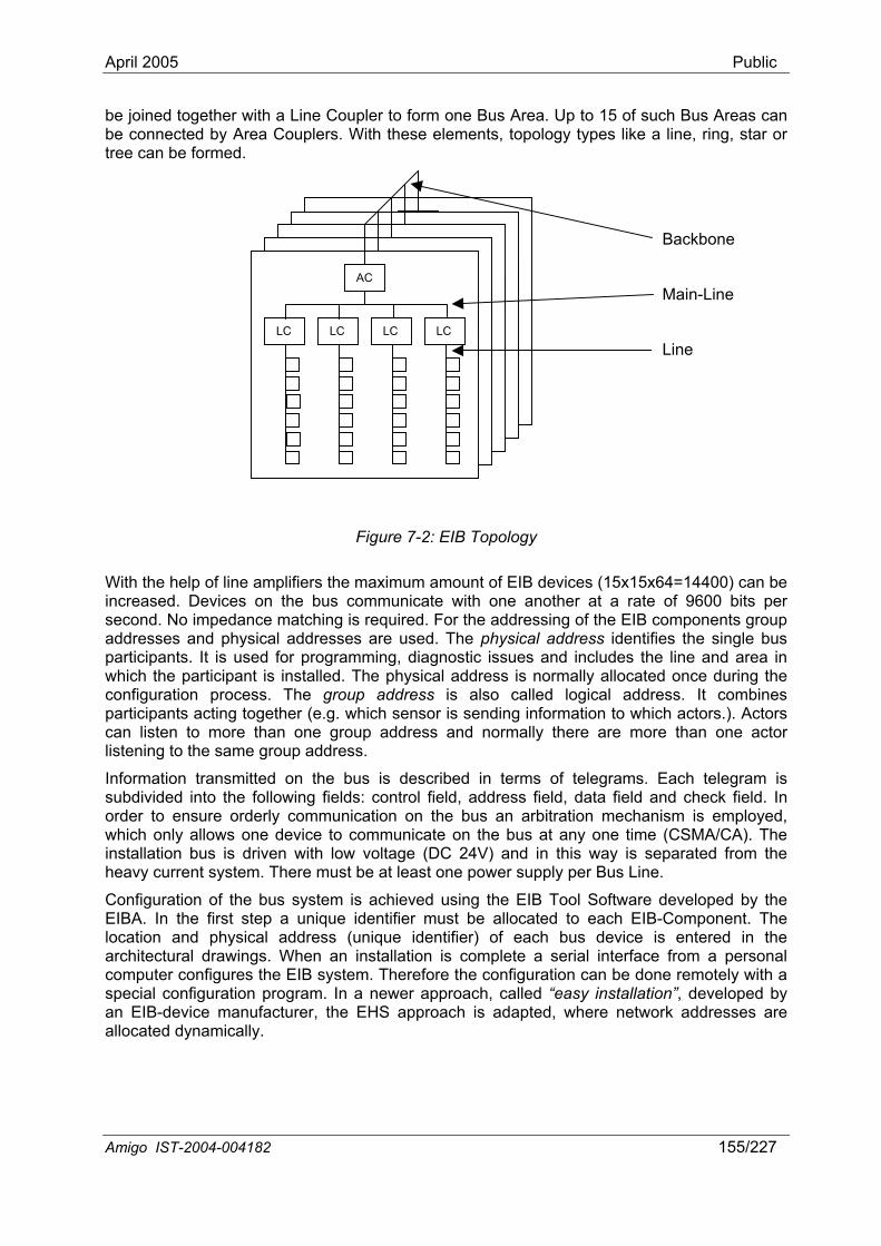
April 2005 Public
be join ith a Line Coupler rea. Up to 15 of such Bus Areas can be con h these elements, topology types like a line, ring, star or tree ca rmed.
Witincrsecond. No impedance matching is required. For the addressing of the EIB components group
parwhicon is also called logical address. It combines
n terms of telegrams. Each telegram is dress field, data field and check field. In
ed together wby Area Couplers. Wit
to form one Bus Anected n be fo
Amigo IST-2004-004182 155/227
Figure 7-2: EIB Topology
h the help of line amplifiers the maximum amount of EIB devices (15x15x64=14400) can be eased. Devices on the bus communicate with one another at a rate of 9600 bits per
addresses and physical addresses are used. The physical address identifies the single bus ticipants. It is used for programming, diagnostic issues and includes the line and area in ch the participant is installed. The physical address is normally allocated once during the figuration process. The group address
participants acting together (e.g. which sensor is sending information to which actors.). Actors can listen to more than one group address and normally there are more than one actor listening to the same group address.
Information transmitted on the bus is described isubdivided into the following fields: control field, adorder to ensure orderly communication on the bus an arbitration mechanism is employed, which only allows one device to communicate on the bus at any one time (CSMA/CA). The installation bus is driven with low voltage (DC 24V) and in this way is separated from the heavy current system. There must be at least one power supply per Bus Line.
Configuration of the bus system is achieved using the EIB Tool Software developed by the EIBA. In the first step a unique identifier must be allocated to each EIB-Component. The location and physical address (unique identifier) of each bus device is entered in the architectural drawings. When an installation is complete a serial interface from a personal computer configures the EIB system. Therefore the configuration can be done remotely with a special configuration program. In a newer approach, called “easy installation”, developed by an EIB-device manufacturer, the EHS approach is adapted, where network addresses are allocated dynamically.
LC LC LC LC
AC
LC LC LC LC
AC
LC LC LC LC
AC
LC LC LC LC
AC
LC LC LC LC
AC
Backbone
Main-Line
Line
April 2005 Public
7.1.4 KONNEX The Konnex Association41 is the logical consequence of the merging of 3 Associations; BCI (BatiBUS Club International), EIBA (EIB Asssocation) and EHSA (European Home Systems Association) into one single Association. 9 companies, emanating from at least one of the associations mentioned, founded Konnex Association in May 1999. At the moment, the Konnex Association represents approximately 100 leading companies worldwide, operating in the field of Home and Building Electronic Systems.
promote its One-Single-Standard called KNX, built
enlarged with the physical layers, configuration modes and application experience of BatiBUS and EHS; it covers 3 different configuration modes (see Figure 7-3) and 4 different network media till now. The 3 configuration modes, especially S- and E-Mode, meet the needs for certified, as well as for basic trained installers (compare with EHS and EIB). The Automatic configuration mode (A-Mode) is even meant to have domestic s a washing machine or a fridge, connected and configured to the network even by non-trained customers. With the 4 different media in the KNX Standa conditions of the building and the different functions required.
The aim of the Konnex Association is to upon the technical expertise of the 3 legacy associations. This standard will integrate the existing bus systems, which automatically guarantees a full interoperability with other applications. The other interesting aspect for domestic applications is that the standard is designed to have easy access to the World Wide Web. Another goal is to realize a connection between the home to the tele-/information backbone. This will bridge the gap and offer interfaces for telecom companies and the electricity distributors. Their interest in the KNX standard is its easy access to their networks and the One Single communication protocol for all different media. On the one hand, it broadens their possibility to offer extra services towards their clients, and on the other hand, they interest service providers to use their networks for new offers in e-commerce and e-services to the consumer.
The KNX standard is based on the communication stack of EIB
appliances, such a
rd, installers can adapt the network to the
One Standard
Figure 7-3: Levels of the different modes
g 41 http://www.konnex.or
Amigo IST-2004-004182 156/227
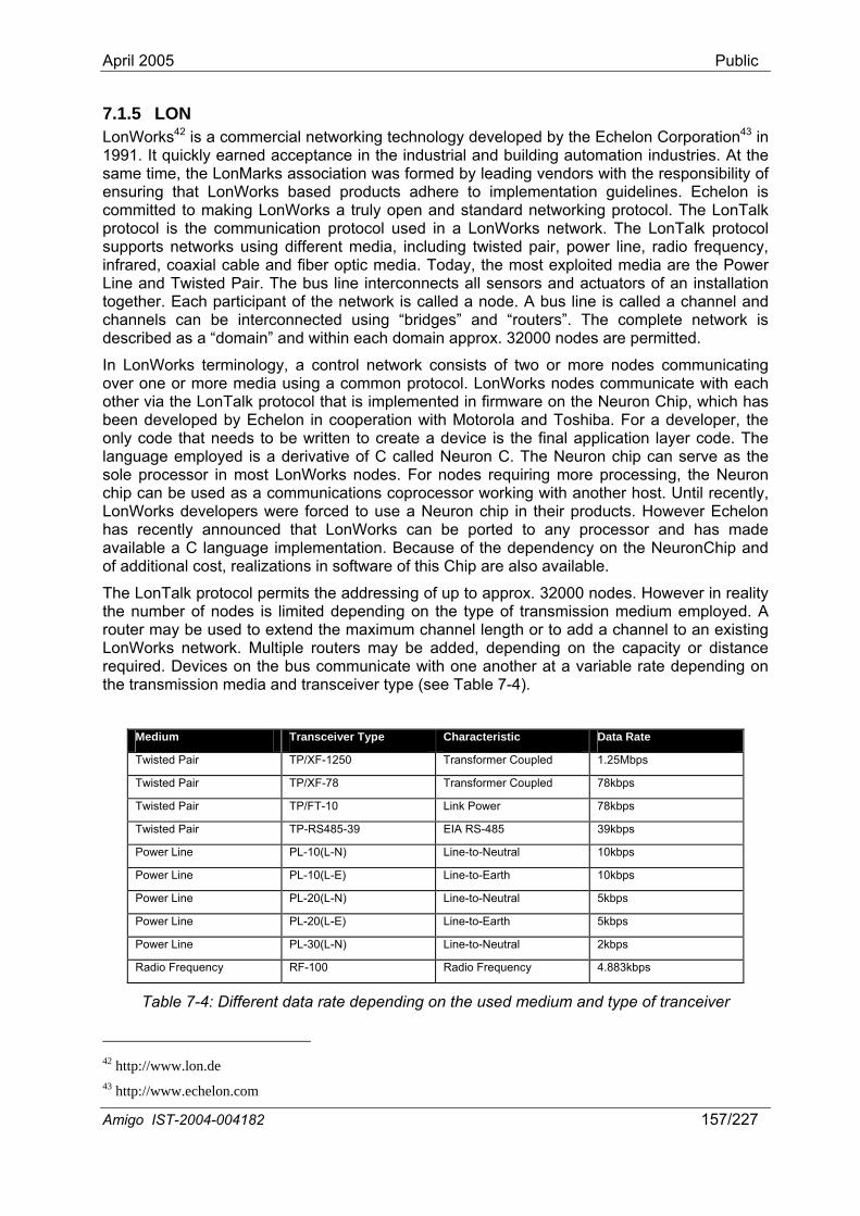
April 2005 Public
7.1.5 LON LonWorks42 is a commercial networking technology developed by the Echelon Corporation43 in 1991. It quickly earned acceptance in the industrial and building automation industries. At the same time, the LonMarks association was formed by leading vendors with the responsibility of ensurin ion guidelines. Echelon is commi king protocol. The LonTalk protocol is the communica rk. The LonTalk protocol supports networks using different media, including twisted infrared, coaxial cable and fiber optic media. Today, the most exploited media are the Power
sors and actuators of an installation d a node. A bus line is called a channel and
te a device is the final application layer code. The language employed is a derivative of C called Neuron C. The Neuron chip can serve as the sole processor in most LonWorks nodes. For nodes requiring more processing, the Neuron chip ca be used as a communications coprocessor working with another host. Until recently, LonWorks developers were forced to use a Neuron chip in their products. However Echelon has recently announced that LonWorks can be ported to any processor and has made available a C language implementation. Because of the dependency on the NeuronChip and of additional cost, realizations in software of this Chip are also available.
The LonT addressing of up to approx. 32000 nodes. However in reality the number of nodes is limited depending on the type of transmission medium employed. A router may be used to extend the maximum channel length or to add a channel to an existing LonWorks network. Mu capacity or distance required. Devices on the bus communicate with one another at a variable rate depending on the transmission media and transceiver type (see Table 7-4).
g that LonWorks based products adhere to implementattted to making LonWorks a truly open and standard networ
tion protocol used in a LonWorks netwo pair, power line, radio frequency,
Line and Twisted Pair. The bus line interconnects all sentogether. Each participant of the network is callechannels can be interconnected using “bridges” and “routers”. The complete network is described as a “domain” and within each domain approx. 32000 nodes are permitted.
In LonWorks terminology, a control network consists of two or more nodes communicating over one or more media using a common protocol. LonWorks nodes communicate with each other via the LonTalk protocol that is implemented in firmware on the Neuron Chip, which has been developed by Echelon in cooperation with Motorola and Toshiba. For a developer, the only code that needs to be written to crea
n
alk protocol permits the
ltiple routers may be added, depending on the
Medium Transceiver Type Characteristic Data Rate
Twisted Pair TP/XF-1250 Transformer Coupled 1.25Mbps
Twisted Pair TP/XF-78 Transformer Coupled 78kbps
Twisted Pair TP/FT-10 Link Power 78kbps
Twisted Pair TP-RS485-39 EIA RS-485 39kbps
Power Line PL-10(L-N) Line-to-Neutral 10kbps
Power Line PL-10(L-E) Line-to-Earth 10kbps
Power Line PL-20(L-N) Line-to-Neutral 5kbps
Power Line PL-20(L-E) Line-to-Earth 5kbps
Power Line PL-30(L-N) Line-to-Neutral 2kbps
Radio Frequency RF-100 Radio Frequency 4.883kbps
Table 7-4: Different data rate depending on the used medium and type of tranceiver
42 http://www.lon.de 43 http:// lon.com www.eche
Amigo IST-2004-004182 157/227
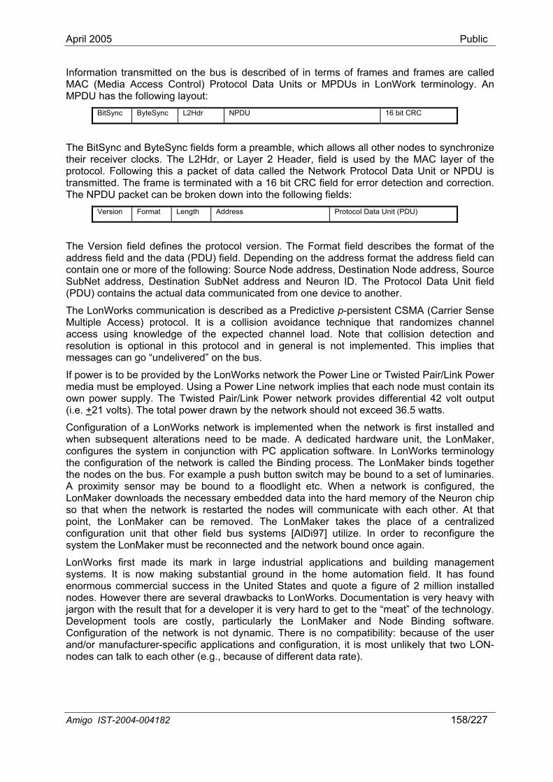
April 2005 Public
Information transmitted on the bus is described of in terms of frames and frames are called AC (Media Access Control) Protocol Data Units or MPDUs in LonWork terminology. An PDU has the following layout:
BitSync ByteSync L2 16 bit CRC
MM
Hdr NPDU
which allows all other nodes to synchronize The BitSync and ByteSync fields form a preamble,their receiver clocks. The L2Hdr, or Layer 2 Header, field is used by the MAC layer of the protocol. Following this a packet of data called the Network Protocol Data Unit or NPDU is transmitted. The frame is terminated with a 16 bit CRC field for error detection and correction. The NPDU packet can be broken down into the following fields:
Version Format Length Address Protocol Data Unit (PDU)
The Version field defines the protocol version. address field and the data
The Format field describes the format of the (PDU) field. Depending on the address format the address field can
and resolution is optional in this protocol and in general is not implemented. This implies that messages can go “undelivered” on the bus.
If power is to be provided by the LonWorks network the Power Line or Twisted Pair/Link Power media must be employed. Using a Power Line network implies that each node must contain its own power supply. The Twisted Pair/Link Power network provides differential 42 volt output (i.e. +
contain one or more of the following: Source Node address, Destination Node address, Source SubNet address, Destination SubNet address and Neuron ID. The Protocol Data Unit field (PDU) contains the actual data communicated from one device to another.
The LonWorks communication is described as a Predictive p-persistent CSMA (Carrier Sense Multiple Access) protocol. It is a collision avoidance technique that randomizes channel access using knowledge of the expected channel load. Note that collision detection
21 volts). The total power drawn by the network should not exceed 36.5 watts.
Configuration of a LonWorks network is implemented when the network is first installed and when subsequent alterations need to be made. A dedicated hardware unit, the LonMaker, configures the system in conjunction with PC application software. In LonWorks terminology the configuration of the network is called the Binding process. The LonMaker binds together the nodes on the bus. For example a push button switch may be bound to a set of luminaries. A proximity sensor may be bound to a floodlight etc. When a network is configured, the LonMaker downloads the necessary embedded data into the hard memory of the Neuron chip so that when the network is restarted the nodes will communicate with each other. At that point, the LonMaker can be removed. The LonMaker takes the place of a centralized configuration unit that other field bus systems [AlDi97] utilize. In order to reconfigure the system the LonMaker must be reconnected and the network bound once again.
LonWorks first made its mark in large industrial applications and building management systems. It is now making substantial ground in the home automation field. It as found enormous commercial success in te a figure of 2 million installed nodes. However there are severa ocumentation is very heavy with jargon with the result that for a developer it is very hard to get to the “meat” of the technology. Development tools are costly, particularly the LonMaker and Node Binding software.
ynamic. There is no compatibility: because of the user
h the United States and quol drawbacks to LonWorks. D
Configuration of the network is not dand/or manufacturer-specific applications and configuration, it is most unlikely that two LON-nodes can talk to each other (e.g., because of different data rate).
Amigo IST-2004-004182 158/227
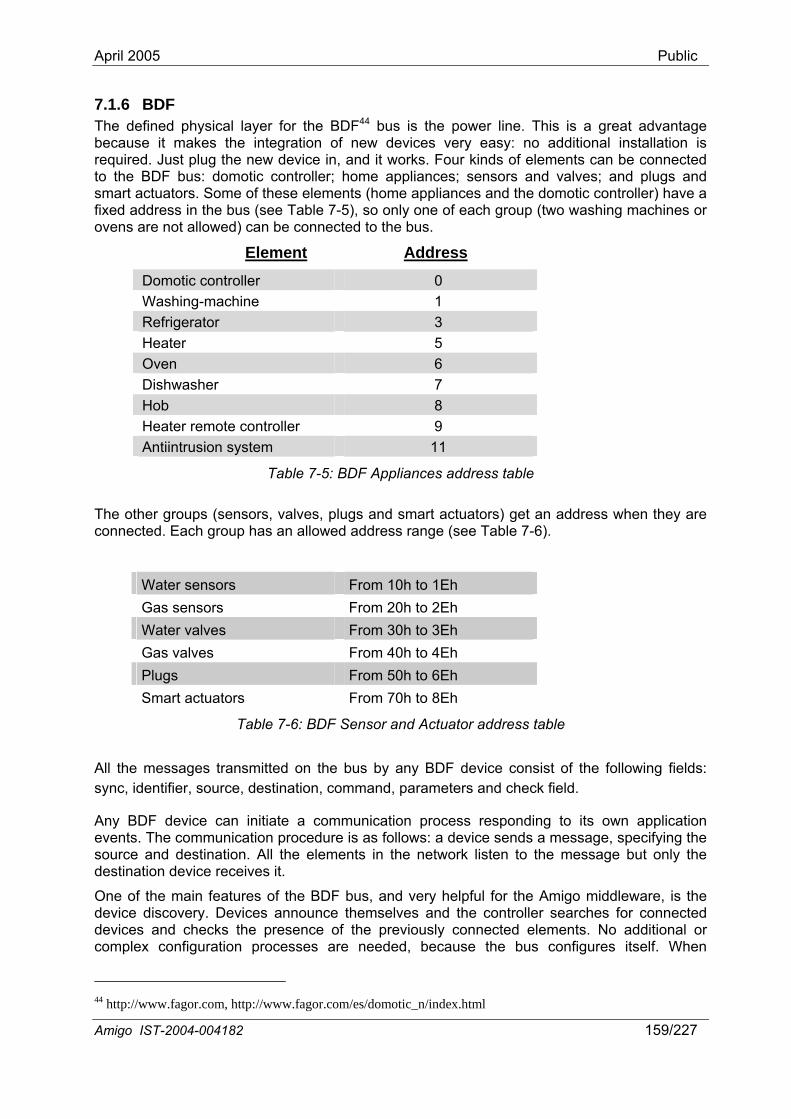
April 2005 Public
7.1.6 BDF The defined physical layer for the BDF44 bus is the power line. This is a great advantage because it makes the integration of new devices very easy: no additional installation is required. Just plug the new device in, and it works. Four kinds of elements can be connected to the BDF bus: domotic controller; home appliances; sensors and valves; and plugs and smart actuators. Some of these elements (home appliances and the domotic controller) have a fixed address in the bus (see Table 7-5), so only one of each group (two washing machines or ovens are not allowed) can be connected to the bus.
Element Address
Domotic controller 0 Washing-machine 1 Refrigerator 3 Heater 5 Oven 6 Dishwasher 7 Hob 8 Heater remote controller 9 Antiintrusion system 11
Table 7-5: BDF Appliances address table
The other groups (sensors, valves, plugs and smart actuators) get an address when they are connected. Each group has an allowed address range (see Table 7-6).
Water sensors From 10h to 1Eh Gas sensors From 20h to 2Eh Water valves From 30h to 3Eh Gas valves From 40h to 4Eh Plugs From 50h to 6Eh Smart actuators From 70h to 8Eh
Table 7-6: BDF Sensor and Actuator address table
All the messages transmitted on the bus by any BDF device consist of the following fields: sync, identifier, source, destination, command, parameters and check field.
Any BDF device can initiate a communication process responding to its own application events. The communication procedure is as follows: a device sends a message, specifying the source and destination. All the elements in the network listen to the message but only the destination device receives it.
One of the main features of the BDF bus, and very helpful for the Amigo middleware, is the device discovery. Devices announce themselves and the controller searches for connected devices and checks the ents. No additional or complex configuration processes are needed, because the bus configures itself. When
presence of the previously connected elem
44 http://www.fagor.com, http://www.fagor.com/es/domotic_n/index.html
Amigo IST-2004-004182 159/227
April 2005 Public
connected, the domotic controller broadcasts a “search” message in the bus. This message announces the presence of the controller in the network and enforces a presentation process in the listening devices. The response to the “search” message depends on the device address:
• Home appliances (fixed address devices): these devices respond to the “search” sending a “notify” message to the controller announcing their presence and describing their status, so that the controller can include them in its current device list. Whenever a device is connected, it sends a “notify” message announcing itself.
• Non-fixed address devices: as they don’t have a fixed address in the network (just an er must provide them a valid and unique bus address
). HAVi-compliant
allowed address range), the controllwhen they are connected to the bus. Once they have obtained it, they save it and behave as a fixed address device.
Periodically, the domotic controller checks the presence of the previously connected elements, refreshing its device list.
7.2 Amigo domotic service architecture The Amigo domotic service architecture aims at integrating the diverse existing domotic systems towards flexible, networked domotic services provision in the Amigo home environment. Thus, mainly based on the level of proprietarity involved in the interaction with the Amigo middleware, we propose to define a set of Amigo domotic device classes, and we provide different solutions to integrate these devices into the Amigo middleware, depending on their class (Section 7.2.1). We then identify the components of the Amigo domotic architecture, which enable in a structured way common, domotic technology-independent networked interfaces for domotic devices employing diverse domotic technologies. These architectural components comply with the Amigo abstract reference service architecture. The introduced Amigo domotic device classes are then mapped onto the Amigo domotic architecture (Section 7.2.2). We finally introduce development and use of domotic scenarios for enabling complex domotic tasks involving multiple devices (Section 7.2.3).
7.2.1 Amigo domotic device classes Our proposal for a set of Amigo domotic device classes is quite similar to the HAVi classification45. HAVi classifies Consumer Electronics (CE) devices into four categories: Full AV (FAV), Intermediate AV (IAV), Base AV (BAV) and Legacy AV (LAVdevices are those in the first three categories, while all other CE devices fall into the fourth category. Similarly, we define Full, Intermediate, Base and Legacy Amigo domotic devices.
7.2.1.1 Legacy Amigo domotic device This is a very simple domotic device that is not integrated in a domotic bus; thus, it does not need any domotic bus support. As it is a rather isolated element, communication with this device will be based on proprietary protocols with a strong dependency on manufacturer technologies. Due to this dependency, it cannot be discovered by standard service discovery protocols like UPnP, Jini, SLP, etc. Amigo service discovery incorporates these standardized protocols; thus, Legacy devices, as they do not support any of these SDPs, cannot be used directly and transparently by Amigo applications. We shall provide a mechanism to make this kind of devices available in the Amigo environment. An example of a Legacy Amigo device is a single lamp controlled via RS232 (see Figure 7-4): it has no domotic bus support, it is not an
45 http://www.havi.org/
Amigo IST-2004-004182 160/227
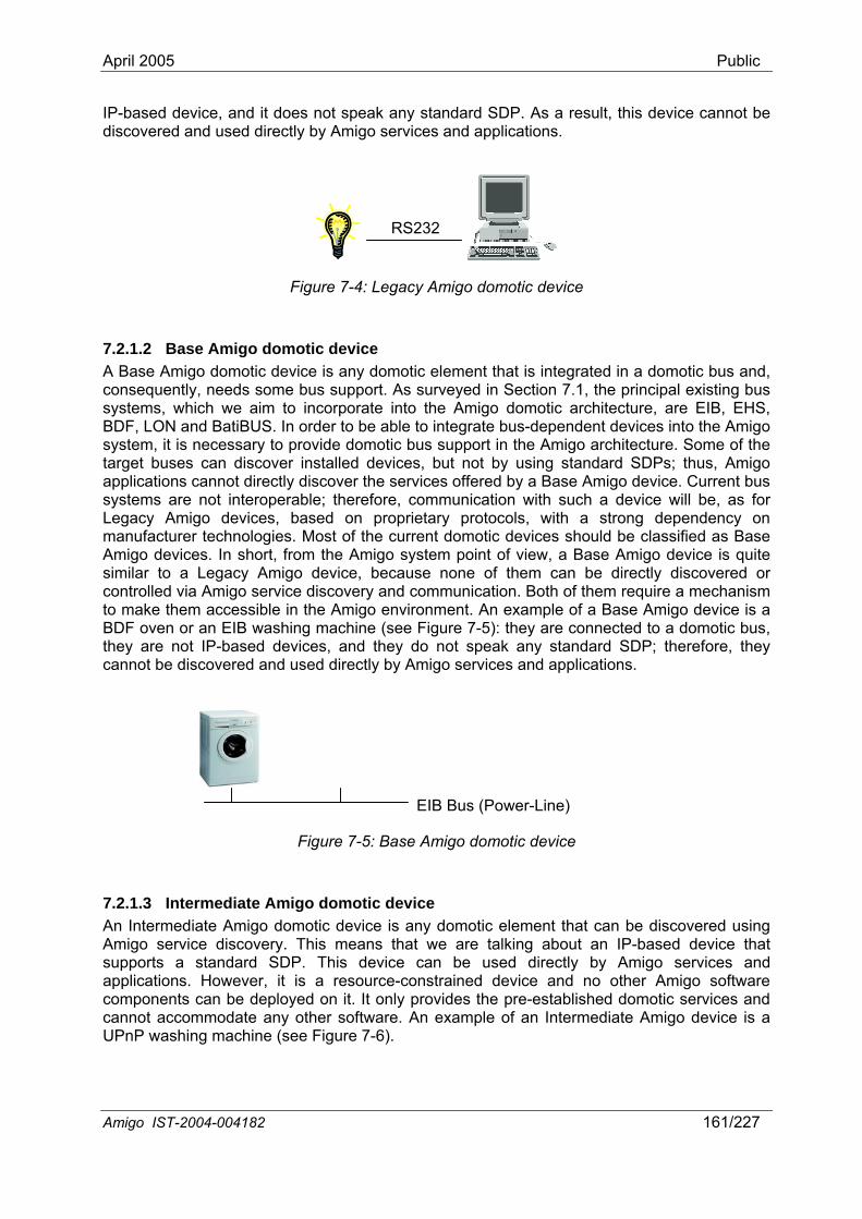
April 2005 Public
IP-based device, and it does not speak any sta dard SDP. As a result, this device cannot be discovered and used directly by Amigo services and applications.
n
Amigo IST-2004-004182 161/227
RS232
Figure 7-4: Legacy Amigo domotic device
Base Amigo domotic device Amigo domotic device is any domotic element that is integrated in a domotic bus and, uently, needs some bus support. As surveyed in Sec
7.2.1.2 A Baseconseq tion 7.1, the principal existing bus sysBD Lsystemtarget applicasystemLegacymanufacturer technologies. Most of the current domotic devices should be classified as Base Am similar controlled via Amigo service discovery and communication. Both of them require a mechanism to m k e is a BD v c bus, they are not IP-based devices, and they do not speak any standard SDP; therefore, they
ectly by Amigo services and applications.
tems, which we aim to incorporate into the Amigo domotic architecture, are EIB, EHS, F, ON and BatiBUS. In order to be able to integrate bus-dependent devices into the Amigo
, it is necessary to provide domotic bus support in the Amigo architecture. Some of the buses can discover installed devices, but not by using standard SDPs; thus, Amigo tions cannot directly discover the services offered by a Base Amigo device. Current bus s are not interoperable; therefore, communication with such a device will be, as for Amigo devices, based on proprietary protocols, with a strong dependency on
igo devices. In short, from the Amigo system point of view, a Base Amigo device is quite to a Legacy Amigo device, because none of them can be directly discovered or
a e them accessible in the Amigo environment. An example of a Base Amigo devicF o en or an EIB washing machine (see Figure 7-5): they are connected to a domoti
cannot be discovered and used dir
EIB Bus (Power-Line)
Figure 7-5: Base Amigo domotic device
7.2.1.3 Intermediate Amigo domotic device
An Intermediate Amigo domotic device is any domotic element that can be discovered using Amigo service discovery. This means that we are talking about an IP-based device that supports a standard SDP. This device can be used directly by Amigo services and applications. However, it is a resource-constrained device and no other Amigo software components can be deployed on it. It only provides the pre-established domotic services and cannot accommodate any other software. An example of an Intermediate Amigo device is a UPnP washing machine (see Figure 7-6).
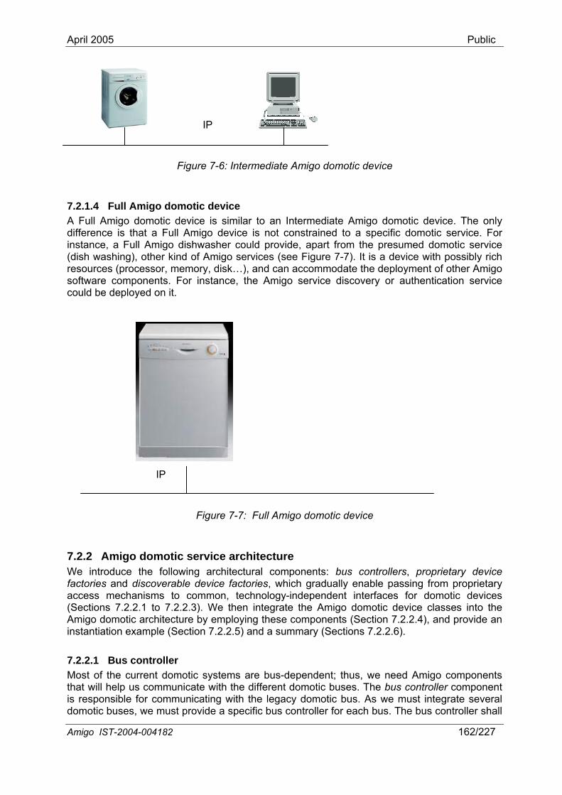
April 2005 Public
IP
Figure 7-6: Intermediate Amigo domotic device
7.2.1.4 Full Amigo domotic device A Full Amigo domotic device is similar to an Intermediate Amigo domotic device. The only difference is that a Full Amigo device is not constrained to a specific domotic service. For instance, a Full Amigo dishwasher could provide, apart from the presumed domotic service (dish washing), other kind of Amigo services (see Figure 7-7). It is a device with possibly rich resources (processor, memory, disk…), and can accommodate the deployment of other Amigo software components. For instance, the Amigo service discovery or authentication service could be deployed on it.
IP
Figure 7-7: Full Amigo domotic device
7.2.2 Amigo domotic service architecture We introduce the following architectural components: bus controllers, proprietary device factories and discoverable device factories, which gradually enable passing from proprietary access mechanisms to common, technology-independent interfaces for domotic devices (Sections 7.2.2.1 to 7.2.2.3). We then integrate the Amigo domotic device classes into the Amigo domotic architecture by employing these components (Section 7.2.2.4), and provide an instantiation example (Section 7.2.2.5) and a summary (Sections 7.2.2.6).
7.2.2.1 Bus controller Most of the current domotic systems are bus-dependent; thus, we need Amigo components that will help us communicate with the different domotic buses. The bus controller component is responsible for communicating with the legacy domotic bus. As we must integrate several domotic buses, we must provide a specific bus controller for each bus. The bus controller shall
Amigo IST-2004-004182 162/227
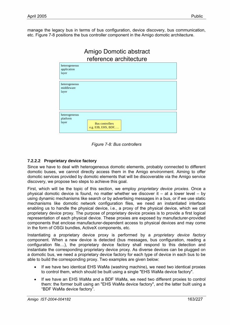
April 2005 Public
manage the legacy bus in terms of bus configuration, device discovery, bus communication, etc. Figure 7-8 positions the bus controller component in the Amigo domotic architecture.
Amigo Domotic abstract reference architecture
heterogeneousmiddlewarelayer
heterogeneousplatformlayer
heterogeneousapplicationlayer
Bus controllerse.g. EIB, EHS, BDF, …
Figure 7-8: Bus controllers
7.2.2.2 Proprietary device factory Since we have to deal with heterogeneous domotic elements, probably connected to different domotic buses, we cannot directly access the nment. Aiming to offer domotic services provided by rable via the Amigo service discovery, we propose two steps to achieve this goal.
s section, we employ proprietary device proxies. Once a o matter whether we discover it – at a lower level – by
an instantiated interface ena e, which we call proprietary device proxy. The purpose of propr represe acomponenin the form
Instantiatin e proxy is performed by a proprietary device factory compo n s configuration, reading a
ing a single "EHS WaMa device factory".
S WaMa and a BDF WaMa, we need two different proxies to control vice factory", and the latter built using a
m in the Amigo enviro domotic elements that will be discove
First, which will be the topic of thiphysical domotic device is found, nusing dynamic mechanisms like search or by advertising messages in a bus, or if we use static mechanisms like domotic network configuration files, we need
bling us to handle the physical device, i.e., a proxy of the physical devicietary device proxies is to provide a first logical
nt tion of each physical device. These proxies are exposed by manufacturer-provided ts that enclose manufacturer-dependent access to physical devices and may come of OSGi bundles, ActiveX components, etc.
g a proprietary devicne t. When a new device is detected (bus messages, bu
configuration file…), the proprietary device factory shall respond to this detection and instantiate the corresponding proprietary device proxy. As diverse devices can be plugged on a domotic bus, we need a proprietary device factory for each type of device in each bus to be able to build the corresponding proxy. Two examples are given below:
• If we have two identical EHS WaMa (washing machine), we need two identical proxies to control them, which should be built us
• If we have an EHthem: the former built using an "EHS WaMa de“BDF WaMa device factory”.
Amigo IST-2004-004182 163/227
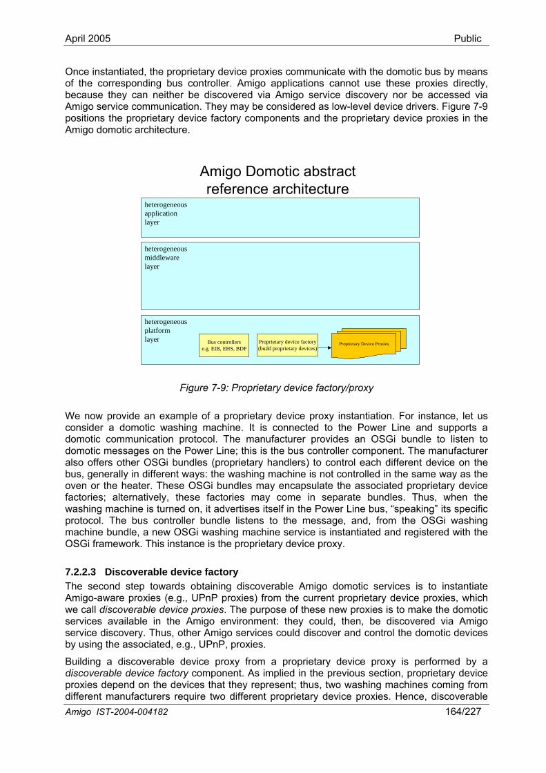
April 2005 Public
Once instantiated, the proprietary device proxies communicate with the domotic bus by means directly,
via considered as low-level device drivers. Figure 7-9
tary device proxies in the
of the corresponding bus controller. Amigo applications cannot use these proxies because they can neither be discovered via Amigo service discovery nor be accessedAmigo service communication. They may bepositions the proprietary device factory components and the proprieAmigo domotic architecture.
Amigo Domotic abstract reference architecture
heterogeneousapplicationlayer
heteromidd
geneousleware
layer
heterogeneousplatformlayer Bus controllers
e.g. EIB, EHS, BDFProprietary device factory(build proprietary devices)
Proprietary Device Proxies
rietary device factory/proxy
We now provide an example ntiation. For instance, let us consider a domotic washing machine. It is connected to the Power Line and supports a domotic communication protocol. The manufacturer provides an OSGi bundle to listen to
r Line; this is the bus controller component. The manufacturer
es is to instantiate P proxies) from the current proprietary device proxies, which
r xies. The purpose of these new proxies is to make the domotic services available in the Am n, be discovered via Amigo service discovery. Thus, other d control the domotic devices by using the associated, e.g., UPnP, proxies.
evice proxy from a proprietary device proxy is performed by a
Figure 7-9: Prop
of a proprietary device proxy insta
domotic messages on the Powealso offers other OSGi bundles (proprietary handlers) to control each different device on the bus, generally in different ways: the washing machine is not controlled in the same way as the oven or the heater. These OSGi bundles may encapsulate the associated proprietary device factories; alternatively, these factories may come in separate bundles. Thus, when the washing machine is turned on, it advertises itself in the Power Line bus, “speaking” its specific protocol. The bus controller bundle listens to the message, and, from the OSGi washing machine bundle, a new OSGi washing machine service is instantiated and registered with the OSGi framework. This instance is the proprietary device proxy.
7.2.2.3 Discoverable device factory The second step towards obtaining discoverable Amigo domotic servicAmigo-aware proxies (e.g., UPnwe call discoverable device p o
igo environment: they could, the Amigo services could discover an
Building a discoverable ddiscoverable device factory component. As implied in the previous section, proprietary device proxies depend on the devices that they represent; thus, two washing machines coming from different manufacturers require two different proprietary device proxies. Hence, discoverable Amigo IST-2004-004182 164/227
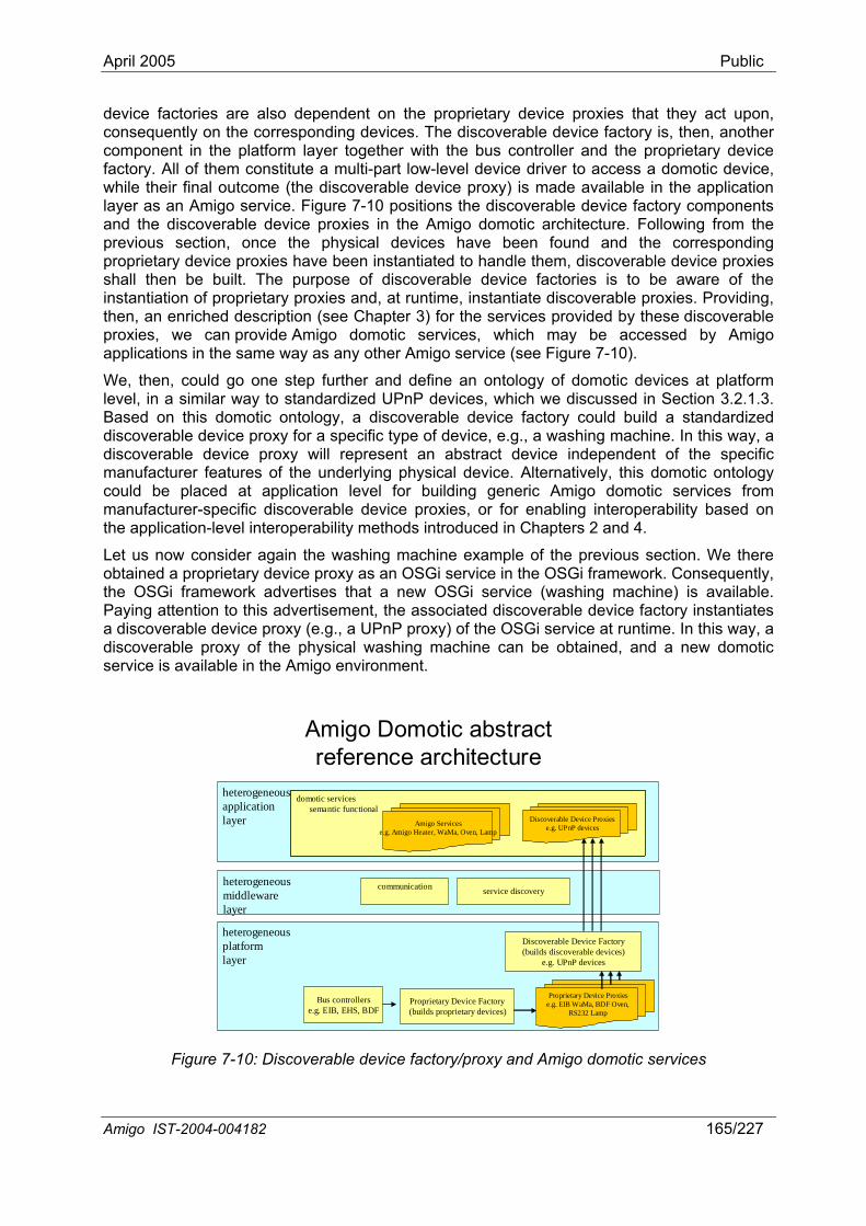
April 2005 Public
device factories are also dependent on the proprietary device proxies that they act upon, consequently on the corresponding devices. The discoverable device factory is, then, another component in the platform layer together with the bus controller and the proprietary device factory. All of them constitute a multi-part low-level device driver to access a domotic device, while their final outcome (the discoverable device proxy) is made available in the application layer as an Amigo service. Figure 7-10 positions the discoverable device factory components
s in the Amigo domotic architecture. Following from the ce the physical devices have been found and the corresponding
a proprietary device proxy as an OSGi service in the OSGi framework. Consequently, e OSGi framework advertises that a new OSGi service (washing machine) is available.
Paying attention to this advertisement, the associated discoverable device factory instantiates a discoverable device proxy (e.g., a UPnP proxy) of the OSGi service at runtime. In this way, a discoverable proxy of the physical washing machine can be obtained, and a new domotic service is available in the Amigo environment.
and the discoverable device proxieprevious section, onproprietary device proxies have been instantiated to handle them, discoverable device proxies shall then be built. The purpose of discoverable device factories is to be aware of the instantiation of proprietary proxies and, at runtime, instantiate discoverable proxies. Providing, then, an enriched description (see Chapter 3) for the services provided by these discoverable proxies, we can provide Amigo domotic services, which may be accessed by Amigo applications in the same way as any other Amigo service (see Figure 7-10).
We, then, could go one step further and define an ontology of domotic devices at platform level, in a similar way to standardized UPnP devices, which we discussed in Section 3.2.1.3. Based on this domotic ontology, a discoverable device factory could build a standardized discoverable device proxy for a specific type of device, e.g., a washing machine. In this way, a discoverable device proxy will represent an abstract device independent of the specific manufacturer features of the underlying physical device. Alternatively, this domotic ontology could be placed at application level for building generic Amigo domotic services from manufacturer-specific discoverable device proxies, or for enabling interoperability based on the application-level interoperability methods introduced in Chapters 2 and 4.
Let us now consider again the washing machine example of the previous section. We there btained o
th
Amigo Domotic abstract reference architecture
heterogeneousplatformlayer
heterogeneousmiddlewarelayer
communication service discovery
heterogeneousapplicationlayer
Bus controllerse.g. EIB, EHS, BDF
Proprietary Device Factory(builds proprietary devices)
Discoverable Device Factory(builds discoverable devices)
e.g. UPnP devices
Proprietary Device Proxiese.g. EIB WaMa, BDF Oven,
RS232 Lamp
domotic servicessemantic functional
domotic servicessemantic functional
Amigo Servicese.g. Amigo Heater, WaMa, Oven, Lamp
Discoverable Device Proxiese.g. UPnP devices
Figure 7-10: Discoverable device factory/proxy and Amigo domotic services
Amigo IST-2004-004182 165/227
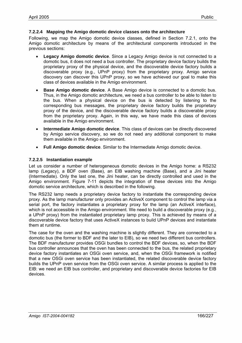
April 2005 Public
7.2.2.4 Mapping the Amigo domotic device classes onto the architecture Following, we map the Amigo domotic device classes, defined in Section 7.2.1, onto the Amigo domotic architecture by means of the architectural components introduced in the previous sections:
• Legacy Amigo domotic device. Since a Legacy Amigo device is not connected to a domotic bus, it does not need a bus controller. The proprietary device factory builds the proprietary proxy of the physical device, and the discoverable device factory builds a discoverable proxy (e.g., UPnP proxy) from the proprietary proxy. Amigo service discovery can discover this UPnP proxy, so we have achieved our goal to make this class of devices available in the Amigo environment.
• Base Amigo domotic device. A Base Amigo device is connected to a domotic bus. Thus, in the Amigo domotic architecture, we need a bus controller to be able to listen to the bus. When a physical device on the bus is detected by listening to the corresponding bus messages, the proprietary device factory builds the proprietary proxy of the device, and the discoverable device factory builds a discoverable proxy from the proprietary proxy. Again, in this way, we have made this class of devices available in the Amigo environment.
• Intermediate Amigo domotic device. This class of devices can be directly discovered by Amigo service discovery, so we do not need any additional component to make them available in the Amigo environment.
• Full Amigo domotic device. Similar to the Intermediate Amigo domotic device.
7.2.2.5 Instantiation example Let us consider a number of heterogeneous domotic devices in the Amigo home: a RS232 lamp (Legacy), a BDF oven (Base), an EIB washing machine (Base), and a Jini heater (Intermediate). Only the last one, the Jini heater, can be directly controlled and used in the Amigo environment. Figure 7-11 depicts the integration of these devices into the Amigo domotic service architecture, which is described in the following.
The RS232 lamp needs a proprietary device factory to instantiate the corresponding device proxy. As the lamp manufacturer only provides an ActiveX component to control the lamp via a serial port, the factory instantiates a proprietary proxy for the lamp (an ActiveX interface), which is not accessible in the Amigo environment. We need to build a discoverable proxy (e.g., a UPnP proxy) from the instantiated proprietary lamp proxy. This is achieved by means of a discoverable device factory that uses ActiveX instances to build UPnP devices and instantiate them at runtime.
The case for the oven and the washing machine is slightly different. They are connected to a domotic bus (the former to BDF and the later to EIB), so we need two different bus controllers. The BDF manufacturer provides OSGi bundles to control the BDF devices, so, when the BDF bus controller announces that the oven has been connected to the bus, the related proprietary device factory instantiates an OSGi oven service, and, when the OSGi framework is notified that a new OSGi oven service has been instantiated, the related discoverable device factory builds the UPnP oven service from the OSGi oven service. A similar process is applied to the EIB: we need an EIB bus controller, and proprietary and discoverable device factories for EIB devices.
Amigo IST-2004-004182 166/227
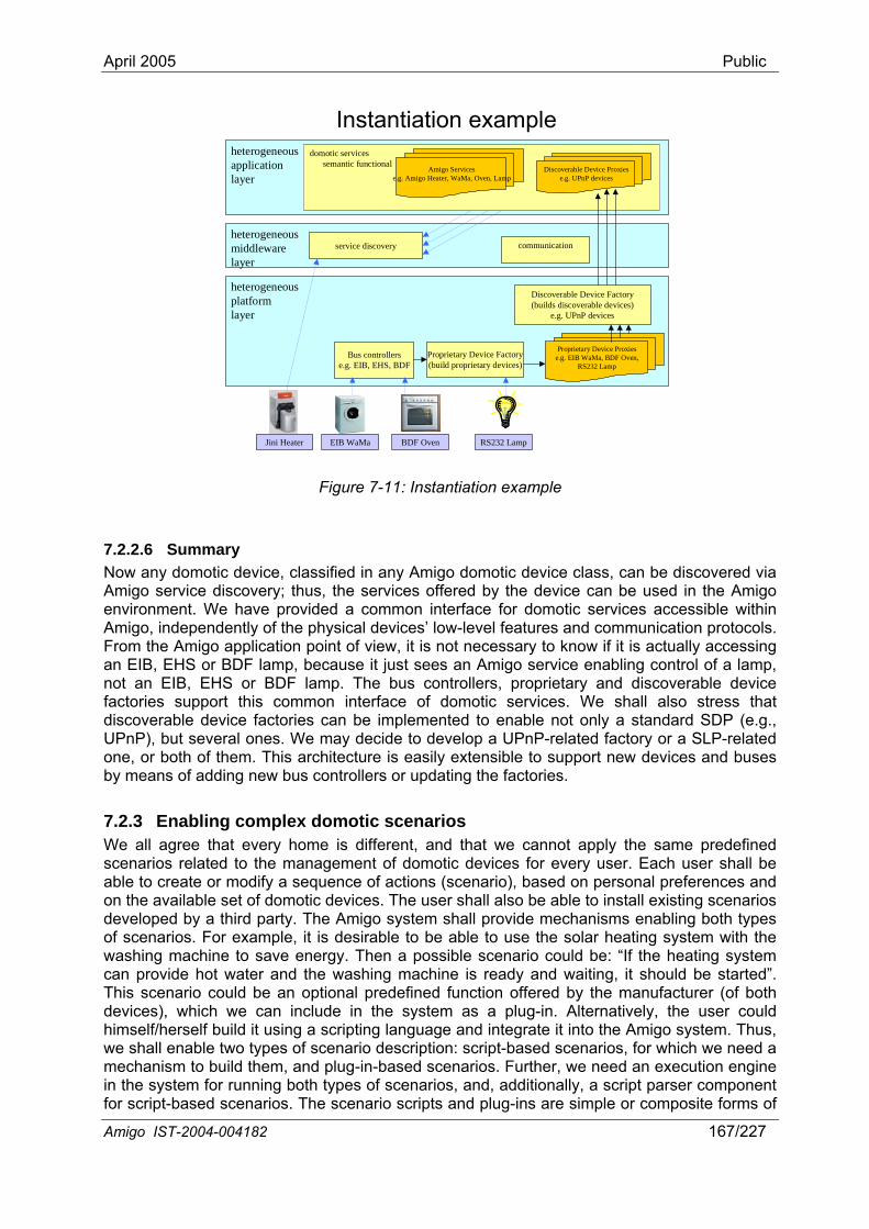
April 2005 Public
heterogeneous
Instantiation exampleheterogeneousapplicationlayer
heterogeneousmiddlewarelayer
communicationservice discovery
Amigo IST-2004-004182 167/227
platformlayer
Bus controllerse.g. EIB, EHS, BDF
Proprietary Device Factory(build proprietary devices)
Discoverable Device Factory(builds discoverable devices)
e.g. UPnP devices
Proprietary Device Proxiese.g. EIB WaMa, BDF Oven,
RS232 Lamp
RS232 LampBDF OvenEIB WaMaJini Heater
domotic servicessemantic functional
Amigo Servicese.g. Amigo Heater, WaMa, Oven, Lamp
Discoverable Device Proxiese.g. UPnP devices
Now nAmigo env nAm ,From tan EIBnot anfactoriediscoverabUPnP), but seone, or both oby means of
7.2.3 EnablWe llscenarable to modify a sequence of actions (scenario), based on personal preferences and
o save energy. Then a possible scenario could be: “If the heating system can provide hot water and the washing machine is ready and waiting, it should be started”.
ed function offered by the manufacturer (of both
Figure 7-11: Instantiation example
7.2.2.6 Summary a y domotic device, classified in any Amigo domotic device class, can be discovered via
service discovery; thus, the services offered by the device can be used in the Amigo ment. We have provided a common interface for domotic seriro vices accessible within
igo independently of the physical devices’ low-level features and communication protocols. he Amigo application point of view, it is not necessary to know if it is actually accessing , EHS or BDF lamp, because it just sees an Amigo service enabling control of a lamp, EIB, EHS or BDF lamp. The bus controllers, proprietary and discoverable device s support this common interface of domotic services. We shall also stress that
le device factories can be implemented to enable not only a standard SDP (e.g., veral ones. We may decide to develop a UPnP-related factory or a SLP-related f them. This architecture is easily extensible to support new devices and buses
adding new bus controllers or updating the factories.
ing complex domotic scenarios a agree that every home is different, and that we cannot apply the same predefined
ios related to the management of domotic devices for every user. Each user shall be create or
on the available set of domotic devices. The user shall also be able to install existing scenarios developed by a third party. The Amigo system shall provide mechanisms enabling both types of scenarios. For example, it is desirable to be able to use the solar heating system with the washing machine t
This scenario could be an optional predefindevices), which we can include in the system as a plug-in. Alternatively, the user could himself/herself build it using a scripting language and integrate it into the Amigo system. Thus, we shall enable two types of scenario description: script-based scenarios, for which we need a mechanism to build them, and plug-in-based scenarios. Further, we need an execution engine in the system for running both types of scenarios, and, additionally, a script parser component for script-based scenarios. The scenario scripts and plug-ins are simple or composite forms of
April 2005 Public
services lying in the application layer. The script parser and execution engine are middleware mechanisms used to execute these simple/composite services. Scenario scripts and plug-ins make part of our approach to service composition within Amigo, as established in Chapter 4. Figure 7-12 depicts the integration of scenario-support mechanisms into the Amigo domotic service architecture. We further discuss our approach to script-based scenarios (Section 7.2.3.1), graphical development of scenarios (Section 7.2.3.2) and plug-ins (Section 7.2.3.3) in the following.
heterogeneousplatformlayer
Amigo Domotic abstract reference architecture
heterogeneousapplicationlayer
heterogeneousmiddlewarelayer
communicationservice discovery
Amigo IST-2004-004182 168/227
Bus controllersDFe.g. EIB, EHS, B
Proprietary device factory(build proprietary devices)
Discoverable Device Factory(builds di
e.g. scoverable devices)UPnP devices
Proprietary Devie.g. EIB WaMa,
ce Proxies BDF Oven,
RS232 Lamp
RS232 LampBDF Oven
Script parserExecution Engine
Scenario Script
Scenario Plug-in
domotic servicessemantic functional Amigo Services
e.g. Amigo Heater, WaMa,Oven, Lamp
Discoverable Devicese.g. UPnP devices
Jini Heater EIB WaMa
bedroom or in the living-room and the TV is off (he is not watching TV en (where the washing
announcing that the washing
-room lamp to be set on.”
In service ll be able to ask Am at homabove proposed scenar
Figure 7-12: Scenarios and plug-ins
7.2.3.1 Script-based scenarios Script-based scenarios are sets or sequences of actions for a device or a combination of devices aiming at enhancing their functionality. An example may be:
“When the washing machine finishes its work, Mike wants to be notified.
• If he is in thenow), he wants the system to switch on a lamp in the kitchmachine is located), and to output a message machine has finished.
• Otherwise he wants the living
the Amigo home, we will install a set of Amigo devices that will provide simple Amigo s: some sensors will tell us about the location of people at home; we wi
igo devices about their current state; and we will be able to control all the domotic devices e. Thus, each Amigo device provides a number of services, but, if we want to run the
io, we need them to compose and cooperate. This scenario may be realized by the script displayed in Figure 7-13.
<event>WM_Finished <if> <condition> <and>
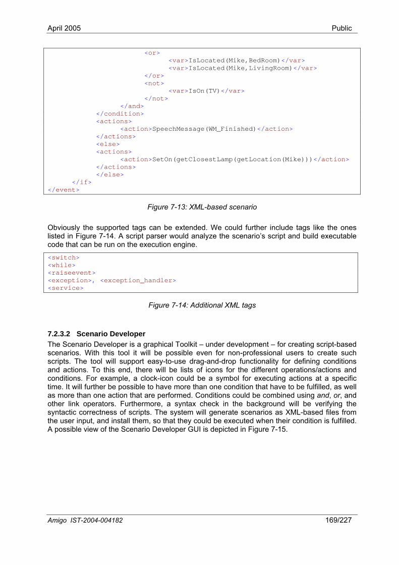
April 2005 Public
<or> <var>IsLocated(Mike,BedRoom)</var> <var>IsLocated(Mike,LivingRoom)</var> </or> <not> <var>IsOn(TV)</var> </not> </and> </condition> ns> <actio <action>SpeechMessage(WM_Finished)</action> </actions> <else> <actions> ation(Mike)))</action> <action>SetOn(getClosestLamp(getLoc </actions> </else> </if> </event>
Figure 7-13: XML-based scenario
Obv slisted in executable cod
<switc
iou ly the supported tags can be extended. We could further include tags like the ones Figure 7-14. A script parser would analyze the scenario’s script and build
e that can be run on the execution engine.
h> <while> <raiseevent> <exception>, <exception_handler> <service>
Figure 7-14: Additional XML tags
l
ecuted when their condition is fulfilled. A possible view of the Scenario Developer GUI is depicted in Figure 7-15.
7.2.3.2 Scenario Developer The Scenario Developer is a graphical Toolkit – under development – for creating script-based scenarios. With this tool it will be possible even for non-professional users to create such scripts. The tool will support easy-to-use drag-and-drop functionality for defining conditions and actions. To this end, there will be lists of icons for the different operations/actions and conditions. For example, a clock-icon could be a symbol for executing actions at a specific time. It will further be possible to have more than one condition that have to be fulfilled, as welas more than one action that are performed. Conditions could be combined using and, or, and other link operators. Furthermore, a syntax check in the background will be verifying the syntactic correctness of scripts. The system will generate scenarios as XML-based files from the user input, and install them, so that they could be ex
Amigo IST-2004-004182 169/227
April 2005 Public
Figure 7-15: Scenario Developer
7.2.3.3 Home plug-ins Plug-ins are software applications that combine several services at an upper level. Specific applications can be very complex, so it may not be possible to realize them as script-based scenarios. Plug-ins can extend existing functionality of basic devices (e.g., provide new
r carry out constant parameter surveillance as test r safety aspects in general. Plug-ins are written in plain
By means of the Amigo domotic service architecture proposed in this chapter, the Amigo home re exposed as domotic
e interfaces for heterogeneous domotic devices. Interoperability between domotic devices and services, key functionality to be provided by the Amigo
tandard service interfaces for domotic devices. We ic services accessible in the Amigo environment,
pport new devices and buses by means of adding new bus controllers or updating the proposed
components. Finally, the use of scenarios and plug-ins
functions for a video recorder), oapplications for failure detection or fojava (instead of a proprietary language as scripts above) and are not necessarily triggered by events.
7.3 Discussion
may be provided with extensible domotic services. Domotic devices aservices, compliant with the Amigo abstract reference service architecture. Due to the current heterogeneity and diversity of domotic devices, buses and device capabilities, it is necessary to provide a well-defined lower-layer domotic architecture, in order to obtain common, technology-independent servic
middleware, is based on enabling these sthus have common interfaces to domotindependent of the physical device specifics and communication protocols. Any domotic device can be discovered via Amigo service discovery; thus, domotic services can be integrated into Amigo applications. This architecture can be extended to su
proprietary/discoverable factoryfacilitates the development of complex domotic applications: users are able to create or modify a sequence of actions, based on personal preferences and on the available set of domotic devices.
Amigo IST-2004-004182 170/227
April 2005 Public
8 Security and Privacy
8.1 Introduction an Amigo home should be as secure as in a normal home. That
ill be used with different capabilities, the range going from those capable of complex processing and data storing by
p, PDA or smart phone, to those that have no storage capability at
sing user security and privacy. The Amigo environment will face a dilemma in regards to security.
nd better services, connectivity is required, but also, this connectivity
tion. This word is used to describe the different techniques to verify that a user/entity is who/what he/it claims to be. There are several means to achieve it, either
ificates, passwords or biometric techniques.
o Symmetric encryption. This category comprises all those algorithms where the d for encryption and decryption of the message is the same. They ecure as long as the key used is not compromised, which is the main
revent the illegal reproduction of copyrighted contents, and fight the piracy of contents on the
Security and privacy is a challenging part in the Amigo project, since it is required to ensure elates to the usability aspect of an
Information and operation inimplies that different services in an Amigo home require different levels of security (for example, the security of the administration services should be quite higher than that of comfortability services.)
In the environment of the Amigo home, lots of different devices w
themselves, such as a laptoall and very reduced processing capacity, if any, such as a light switch or a temperature sensor.
All this digital data that previously was not stored anywhere, or didn’t exist at all, and access to the new network-enabled devices may be valuable for some mischievous users, compromi
In order to provide new aoffers more possibilities for compromising sensible information and access to devices.
The Internet is an open network, therefore it can’t be controlled and anyone can access to it. Looking after users’ safety has been a major concern since its conception, and several means to attain it have been developed over the years:
• Authentica
through digital cert• Encryption/decryption refers to the different techniques to grant message privacy. They
consist in encoding the message in a particular known way which can be later decoded to retrieve the original content. There are lots of different encryption/decryption algorithms, which offer varying degrees of security. They can be classified in two different groups:
key useremain sinconvenience of these algorithms.
o Asymmetric encryption describes those techniques that use different keys for encryption and decryption. It’s more complex and requires more processing capacity, but, generally speaking, it is also more secure.
• DRM protection techniques comprise a great set of techniques devised to p
Internet.
Amigo technologies should try to incorporate all those means of protection, so that users can freely enjoy the new technologies without having to worry about new risks introduced in their normal way of life.
8.1.1 Security and privacy in Amigo
maximum trust from a user’s perspective, and directly rAmigo system. It is possible with today’s technologies to secure any resource or to protect privacy of information, but these technologies are usually designed in the context of corporate or large scale networks. They sacrifice either heterogeneity of devices, network technologies, applications, identification mechanisms and/or usability to achieve their goal. An ambient Amigo IST-2004-004182 171/227
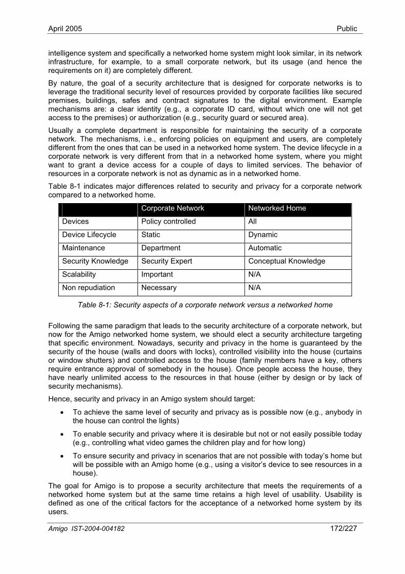
April 2005 Public
intelligence system and specifically a networked home system might look similar, in its network infrastructure, for example, to a small corporate network, but its usage (and hence the requirements on it) are completely different.
By nature, the goal of a security architecture that is designed for corporate networks is to leverage the traditional security level of resources provided by corporate facilities like secured premises, buildings, safes and contract signatures to the digital environment. Example mechanisms are: a clear identity (e.g., a corporate ID card, without which one will not get access to the premises) or authorization (e.g., security guard or secured area).
Usually a complete department is responsible for maintaining the security of a corporate network. The mechanisms, i.e., enforcing policies on equipment and users, are completely different from the ones that can be used in a networked home system. The device lifecycle in a corporate network is very different from that in a networked home system, where you might want to grant a device access for a couple of days to limited services. The behavior of resources in a corporate network is not as dynamic as in a networked home.
Table 8-1 indicates major differences related to security and privacy for a corporate network compared to a networked home.
Corporate Network Networked Home
Devices Policy controlled All
Device Lifecycle Static Dynamic
Maintenance Department Automatic
Security Knowledge Security Expert Conceptual Knowledge
Scalability Important N/A
Non repudiation Necessary N/A
Table 8-1: Security aspects of a corporate network versus a networked home
Following the sam rate network, but now for the Amigo itecture targeting that specific environment. Nowadays, security and privacy in the home is guaranteed by the
e possible with an Amigo home (e.g., using a visitor’s device to see resources in a
e paradigm that leads to the security architecture of a corpo networked home system, we should elect a security arch
security of the house (walls and doors with locks), controlled visibility into the house (curtains or window shutters) and controlled access to the house (family members have a key, others require entrance approval of somebody in the house). Once people access the house, they have nearly unlimited access to the resources in that house (either by design or by lack of security mechanisms).
Hence, security and privacy in an Amigo system should target:
• To achieve the same level of security and privacy as is possible now (e.g., anybody in the house can control the lights)
• To enable security and privacy where it is desirable but not or not easily possible today (e.g., controlling what video games the children play and for how long)
• To ensure security and privacy in scenarios that are not possible with today’s home but will bhouse).
The goal for Amigo is to propose a security architecture that meets the requirements of a networked home system but at the same time retains a high level of usability. Usability is defined as one of the critical factors for the acceptance of a networked home system by its users.
Amigo IST-2004-004182 172/227
April 2005 Public
8.1.2 Relationship to existing security mechanisms Today a variety of security mechanisms like WLAN security, logon for PCs, wireless security for mobile networks, etc., exist that offer a comfortable level of security when using these
/UMTS, Bluetooth)
l of access control: either a device is allowed full access or no
tatic in nature (establish a web-key, once established can be used by everybody)
• Closed solution (authenticated by the mobile network, but can not be used to grant ersa)
device (e.g., video camera or temperature sensor).
ed when
suit le chitecture as needed for the Am
Alte aprim ry(2) simplify desired fun these mechanisms apply only to a specific
ity & privacy architecture that needs to be applied to all domains (PC, CE, mobile and o
Therefo ed that is interoperable and flex espe fic
In t Am Section 8.3. Based on the elicited requirements, we elaborate the Amigo security and privacy arc
cs of the Amigo security and privacy architecture, and hence the
appropriate.
technologies. These mechanisms however all suffer from one or more of the following shortcomings:
• They are infrastructure-dependent (WLAN, GSM/GPRS
• Offer a binary leveaccess at all
• Are not distributed (logon to a specific PC, a single Bluetooth partnership)
• Require trust of a 3rd party (a mobile network)
• Do not offer deferred authorization (see Section 8.4.2.1)
• Are complex to setup
• Are s
access to a WLAN or vice v
• Limited access or authorization revoking possibilities (it is not a trivial task to revoke access of a device on a WLAN, need to know the MAC address)
• Require rich and powerful devices. If security is enabled on a WLAN, the device needs to implement this security, although it might lack the processing power or UI to enter keys in the
Existing security mechanisms often target a specific security risk that was not envisionthe technology was released. They are often specific to a certain technology, and are not
ab as primary building blocks for a security & privacy arigo solution.
rn tively, they might be incorporated in a security architecture (opposed to be used as a building blocks), but this would only be useful if they (1) offer additional functionality or
ctionality. Since most of (network) technology or solve a specific problem, it would not be feasible to incorporate them into a secur
d motics).
re, an Amigo security and privacy architecture is proposibl by design on an application level (including the Amigo middleware), and that puts no ci security and privacy requirements on the different underlying network infrastructures.
he following sections, we first identify a set of scenarios manifesting requirements on the igo security and privacy architecture (Section 8.2). These requirements are derived in
hitecture in Section 8.4. We conclude in Section 8.5.
8.2 Supported scenarios The characteristirequirements on it, are defined by the set of scenarios it has to support. Describing the system on the level of scenarios is sufficient for the purpose of deriving an abstract architecture. For the definition of the concrete implementation, the level of use-cases might be more
Amigo IST-2004-004182 173/227

April 2005 Public
The following scenarios are derived from the higher level Amigo scenarios as described in the Amigo Description of Work, and verified against the refined Amigo scenarios as described in Deliverable D1.2 [Amigo-D1.2].
8.2.1 Installation of (new) equipment New equipment will be introduced into the home on a regular basis. Equipment ranges from statically installed house-hold equipment (e.g., refrigerators) and consumer electronics (TVs) to PCs and mobile equipment like phones, PDAs and laptops. Some of this equipment will be
reign equipment
d smart phones. This equipment should have limited access to functions r e
liste n tching a photo collection.
8.2.3 Equipment malfunction Equipment will malfunction, either by errors in design or due to external causes like power failure, electricity short circuit etc. An Amigo system should take this into account and be designed with a high level of tolerance towards failures. The doom scenario of not being able to perform any functio from the house, communication failure, etc.)
ny means.
example of ild should not be
Acc s d for a limited period. For example a friend that joins the child to play the video game. The equipment brought with the friend is allowed access to the Amigo networked home system for half a day. Another usage is that access to the service itself (playing the video game) might also be limited to one hour.
programmable and capable of storing information, other might not. No specific requirement should be imposed on equipment in an Amigo system. Related to the installation of equipment is also the removal of equipment (broken, sold, etc.).
8.2.2 FoFriends and guests will have their own equipment with them that should be capable of being used in an (other than their own) Amigo home. Examples of this are game consoles, controllers, PDAs aninside the home (e.g., they should be able to turn on and off the light or be used focommunication in the house). This equipment might also be used for temporary access, lik
ni g to music or wa
n (no entrance or exitshould be avoided by a
8.2.4 Equipment is moved outside and back into the home An Amigo home will be comprised of statically located equipment, but also of mobile equipment. This mobile equipment can be either personalized equipment (phone) or domestic equipment. Mobile equipment can be taken out of the Amigo home network (e.g., to work) and return at a later point in time.
8.2.5 Out of home communication Some services inside an Amigo home need to communicate to services outside the Amigo home area (e.g., communication, e-commerce, video on demand). These services might need account information or other sensitive information that should be protected.
8.2.6 Home service usage Access to services in the home should be configurable. Some services might require the approval of an authorized person (other than the one accessing the service). Anthis is a child that wants to play a video game that is rated as violent. The chable to play the video game without explicit approval of a parent.
es might be grante
Amigo IST-2004-004182 174/227
April 2005 Public
8.3Functio ments on the Amigo security and privacy architecture can be derived from the description of an Amigo system and the previous scenarios.
em requiring a
8.3Since the u eing able to ma c detailed knowledge of the n eir implications should directly relate to the Amigo environment as seen by any ly then, the safety level can be maintained and n
Amigo security system, masystemfailure continu
8.3.6 Wh pAmigo (rentedenter thregister these devices over and over again.
8.4 AThe p rgeting the requirements of a networked home system. Basic building blocks for the security and privacy architecture are two middleware services: the authentication service and the authorization
Requirements nal require
8.3.1 Interoperability An Amigo system will contain a large diversity of devices, and it will not be possible to enforce policies on the usage or capabilities of these devices in an Amigo home. Therefore, it is imperative that the security and privacy Architecture takes all these categories of devices into account while still guaranteeing a safe level of security and privacy.
8.3.2 Pre-configured It should not be necessary that a security expert is required to install an Amigo system or verify the security configuration of an Amigo system. The system should guarantee an initial safe level of security and privacy settings. It is very likely that a security systcomplicated or extensive setup before being regarded safe is turned off or not used at all.
.3 User-friendly sers of an Amigo home should not become security experts before b
ke hanges to the system, configuration should be possible without u derlying technologies. Decisions and th
Amigo user. On u derstood.
8.3.4 Self-managed Nobody in an Amigo home should be appointed as the person responsible for the ‘health’ of the Amigo security system. Information necessary for the security system should be maintained by the system itself. If interaction with the security system is inevitable, this interaction should be performed with as few actions as possible and in a – for an Amigo user – natural understandable way.
8.3.5 Distributed Despite quality requirements like reliability and stability on the
lfunction and errors are unavoidable and should be taken into consideration. The security should be as resilient as possible, and, therefore, should not become a single point of in an Amigo home. If part of the security system fails, it should still be possible to e with a limited number of services or limited functionality of these services.
Dynamic ile olicies for a corporate network limit the dynamics of resources (devices, networks), an
home will have to deal with them. Amigo users will bring new or temporary devices , borrowed or carried by visitors) into an Amigo home. These devices will leave and e network frequently, and the user should, for example, not be bothered by having to
migo security and privacy architecture roposed Amigo security and privacy architecture is specifically ta
Amigo IST-2004-004182 175/227
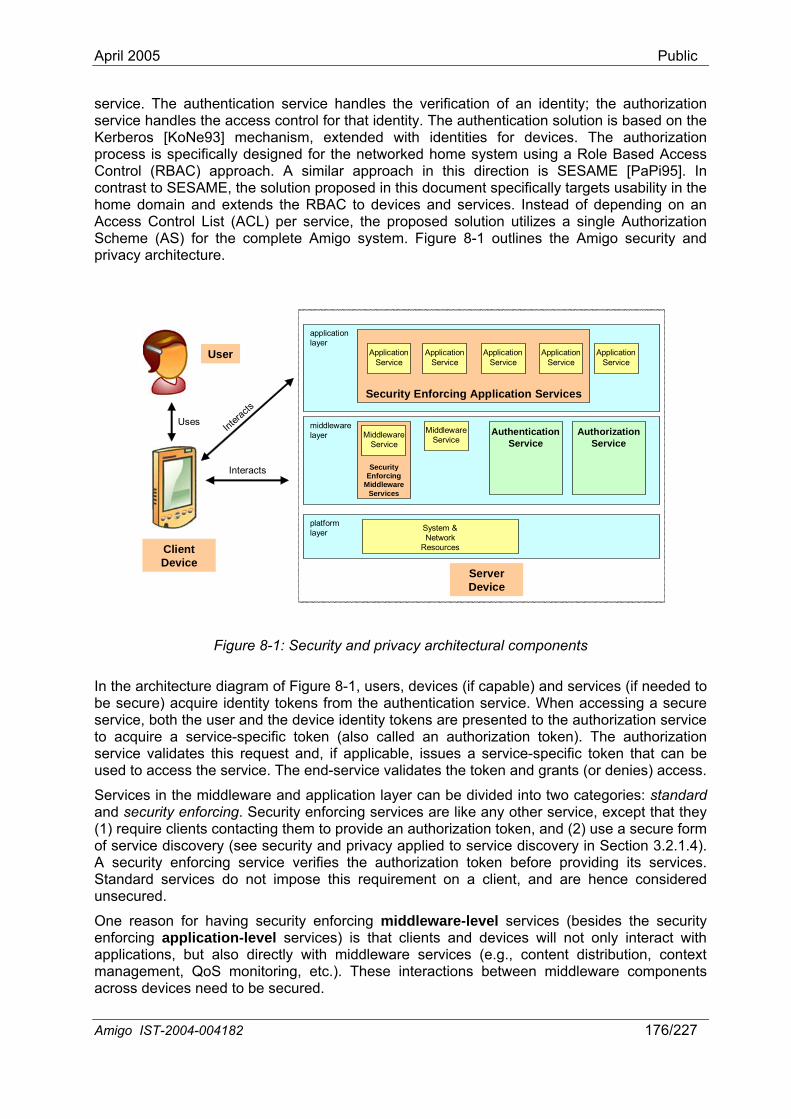
April 2005 Public
service. The authentication service handles the verification of an identity; the authorization service handles the access control for that identity. The authentication solution is based on the Kerberos [KoNe93] mechanism, extended with identities for devices. The authorization process is specifically designed for the networked home system using a Role Based Access Control (RBAC) approach. A similar approach in this direction is SESAME [PaPi95]. In contrast to SESAME, the solution proposed in this document specifically targets usability in the home domain and extends the RBAC to devices and services. Instead of depending on an Access Control List (ACL) per service, the proposed solution utilizes a single Authorization Scheme (AS) for the complete Amigo system. Figure 8-1 outlines the Amigo security and privacy architecture.
Amigo IST-2004-004182 176/227
middlewarelayer
platformlayer
applicationlayer
ApplicationService
Application
Uses
User
CD
lievi
ent ce
Intera
cts
SysteNetw
sou
m &ork
Re rces
Service
Security Enforcing Application Services
MiddlewareServiceMiddleware
Service
Interacts
AuthenticationService
AuthorizationService
ServerDevice
ApplicationService
ApplicationService
Middleware Services
SecurityEnforcing
ApplicationService
Figure 8-1: Security and privacy architectural components
itecture diagram of Figure 8-1, users, evices (i d services (if needed to cqu identity kens f the a ticatio ervice. en acce ing a secure
tion service ire a service-specific token (also calle an auth rization t ken). The authorization
ate s request and, plica es cific tok hat can be e validates the token and grants (or denies) access.
d application layer can be divided into two categories: standard and security enforcing. Security enforcing services are like y (1) require clients contacting th en, and (2) use a secure form of service discovery (see security and privacy applied to service discovery in Section 3.2.1.4). A security enforcing service verifies the authorization token before providing its services.
do not impose this requirement on a client, and are hence considered
application-level services) is that clients and devices will not only interact with appmaacross
In the archbe secure) aservice, both the user and the device identity tokens are presented to the authoriza
duthen
f capable) ann sire to rom Wh ss
to acquservice valid
dble, issu
oa service-spe
os thi if ap en t
used to access the service. The end-servic
Services in the middleware anany other service, except that the
em to provide an authorization tok
Standard servicesunsecured.
One reason for having security enforcing middleware-level services (besides the security enforcing
lications, but also directly with middleware services (e.g., content distribution, context nagement, QoS monitoring, etc.). These interactions between middleware components
devices need to be secured.
April 2005 Public
Anobetwee ices (e.g., content distribution) might use unsecured communication cha e
In the sections, besides authentication (Section 8.4.1) and authorization (Section 8.4.2), privacy (Section 8.4.3) and communication security (Section 8.4.4) are addressed as
rivacy architecture.
ave identities (the Amigo system as such might also have an
introduced.
nario for authentication of a user in Kerberos:
is encrypted with the user’s password.
and decrypts it with his/her password. This token is called anting ticket in Kerberos.
Then, a sas follow
• service, and sends the ticket-granting ticket to the
• T llowed access to that service, and, if allowed, generates another token that is encrypted with the service’s password.
• it.
Users are registered in an Amigo system by a configuration application. Access to this configuration application should be restricted to limited group of users and devices.
ther reason for security enforcement of middleware services is that communication n middleware serv
nn ls (public network) or needs to handle secured content (DRM).
following
essential parts of the Amigo security and p
8.4.1 Authentication Users, devices and services hidentity, but this is not directly applicable to the security within the home) in the proposed architecture. Authentication is the process of verifying an identity. Single sign-on (SSO) is a concept in which a resource is not required to prove its identity every time it wants to access a service, but only has to be authenticated once (once in the context of a session, where the system defines a session). In the following sections, the authorization service (Section 8.4.1.1) and its specialization to users, devices and services (Sections 8.4.1.2 to 8.4.1.4) are
8.4.1.1 Authentication service The authentication service is based on the Kerberos principle, which means that authentication tokens (called ticket-granting tickets in Kerberos) are issued for resources that are authenticated. These authentication tokens can then be used to acquire (service-specific) authorization tokens (tickets in Kerberos) that grant access to the associated services (the principle of using an authentication token multiple times to get authorization tokens realizes the SSO feature).
There follows a simplified example sce
• A user sends his/her user name to the Kerberos system.
• The Kerberos system generates a token that
• The user receives the token the ticket-gr
implified example scenario for accessing a service using the ticket-granting ticket is s:
The user wants to access a Kerberos system with the request to access that service.
he Kerberos system verifies whether the user is a
The user receives the additional token, and presents it to the service when accessing
• The service decrypts the ticket and grants access.
Note that for simplicity reasons, the concept of a session key is skipped, since it does not change the essential principle of Kerberos.
8.4.1.2 Users
a
Amigo IST-2004-004182 177/227
April 2005 Public
Different mechanisms will be used to proof the identity of a user, which can be categorized as
rvice
A u ride yproventhe au s can be retrieved from the authentication pro s
The tokto indiv r the user towards
rvices.
devices that are more or less stationary to devices that o home. Another type of devices is a guest device; it
A device can re-use a token, and can therefore leave and enter the Amigo system without ver and over again (identities can be revoked, so a device with a
strong or weak. Strong proofs are username/password, smartcard or biometric proofs. Weak proofs are single PIN or username.
Weak proofs are in fact identities that can not be verified, and hence solely serve the purpose of identification (in contrast to authentication, where an identity is verified). The role will be encoded in the token issued by the authentication service, and it depends on the sewhether it requires a strong or accepts a weak proof. An example of a service accepting a weak proof could be a service that adjusts room preferences for an Amigo user.
se ’s identity can also be linked to an external (external with respect to the Amigo system) ntit , like, for example, an identity with an e-commerce Web site. If the users identity was
using a method in the strong category (that is, the user possesses a token issued by thentication process), alternative identitie
ce s.
en generated by the authentication service can be used (multiple times) to get access idual services. Providing a token after authentication enables SSO fo
multiple se
To enable RBAC (see Section 8.4.2), users are assigned a role. Examples of user roles are:
• Administrators;
• Family;
• Kids;
• Guests;
• Others (configurable by Amigo users).
8.4.1.3 Devices The devices in an Amigo home will range from powerful programmable devices, like laptops, PDAs and smart phones, to small or simple devices, like temperature sensors, printers or cameras with limited processing power.
The behavior of devices will vary from dynamically enter and leave the Amigenters the Amigo home for a certain period of time and then leaves.
Registration of a device is performed when it is discovered. A device has to acquire a token if it does not possess a valid token (unless it does not plan to access any security enforcing components or is not capable of storing tokens). The authentication process can then decide whether to directly issue a token (because, for example, the built-in token is verified, or the expired one is extended) or get confirmation from an Amigo user (for example, having the Administrators role) before issuing a token.
having to identify itself orevoked identity will not be able to acquire a service-specific authorization token).
Devices also participate in the RBAC (see Section 8.4.2). Example roles are:
• Administrative;
• Domestic;
• Mobile;
• Guest;
Amigo IST-2004-004182 178/227
April 2005 Public
• Unidentifiable (devices not capable or not in possession of a token, including legacy devices).
8.4.1.4 Services Services are the security enforcing components in the Amigo security and privacy architecture. The abstract reference architecture of an Amigo system distinguishes three layers: the platform, middleware and application layer. Amigo services are implemented in the middleware and application layer. Users and devices will directly interact with both layers, and hence there ity enforcing services in both layers.
Services receive their token when they are re inst t ting
. For
ment (e.g., play video games);
On the one hand, the authorization
curity system.
natural or higher level. Assigning (only) to the PC in the study
wever, be relevant to the domain that is to extensible enables
customizable granularity for authorization (e.g., define different roles for children in different age groups).
• Assigning services to roles leverages the concept of natural grouping, and enables a single Authorization Scheme (AS) for the Amigo home. An Amigo user does not need to know and configure every individual service on every Amigo system, but can configure the access based on natural (home-specific) roles for services.
will be secur
gistered (installed) in an Amigo architecturean iation. This token contains (among other data) the key for encrypting and decryp
service discovery information, and can, for example, also be used to verify that the accessed service is the actual service it pretends to be. This is essential to avoid impersonation of services (e.g., a guest device impersonating a service discovery repository, and hence acquiring a complete overview of the devices and services in an Amigo home).
To realize the single Authorization Scheme for RBAC, services are assigned rolesexample:
• Administrative (e.g., user registration, AS configuration);
• Secure (e.g., personal communication services like IM, e-mail);
• Entertain
• Home (e.g., climate control, watch TV).
8.4.2 Authorization Authorization is the process of controlling the access of an identity to a resource. Taking usability or, more generically, the security and privacy requirements of an Amigo system into account, authorization becomes a very complex subject.configuration has to be perfectly secure, in the sense that it does not open or leave any holes in the security concept. On the other hand, authorization will be configured by Amigo Users, who are not security experts spending a lot of time on analyzing the consequences of a change in the se
The proposed architecture addresses this problem in several ways:
• Taking not only the identity of a user but also the identity of a device into account enables decisions on aroom the Administrative role guarantees that somebody in the living room can not access any Administrative service, even if that person would know the administrative password. Assigning to a friend’s PDA device a guest role ensures that this device can only be used for a limited time with limited access in the home.
• Configuring access based on roles is easier to oversee than configuring them on an individual level. These roles should then, hobe secured (in this case the Amigo home). Making the user roles
Amigo IST-2004-004182 179/227
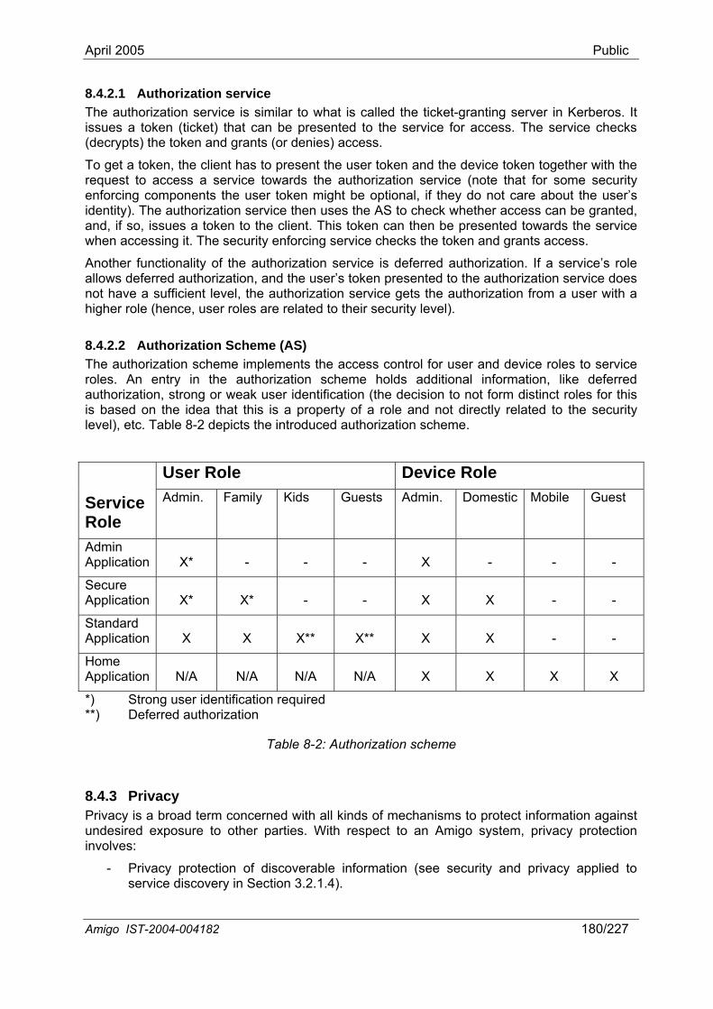
April 2005 Public
8.4.2.1 Authorization service The authorization service is similar to what is called the ticket-granting server in Kerberos. It issues a token (ticket) that can be presented to the service for access. The service checks (decrypts) the token and grants (or denies) access.
To get a token, the client has to present the user token and the device token together with the request to access a service towards the authorization service (note that for some security enforcing components the user token might be optional, if they do not care about the user’s identity). The authorization service then uses the AS to check whether access can be granted, and, if so, issues a token to the client. This token can then be presented towards the service when accessing it. The security enforcing service checks the token and grants access.
Another functionality of the authorization service is deferred authorization. If a service’s role allows deferred authorization, and the user’s token presented to the authorization service does not have a sufficient level, the authorization service gets the authorization from a user with a higher role (hence, user roles are related to their security level).
8.4.2.2 Authorization Scheme (AS)
at this is a property of a role and not directly related to the security
Device Role
The authorization scheme implements the access control for user and device roles to service roles. An entry in the authorization scheme holds additional information, like deferred authorization, strong or weak user identification (the decision to not form distinct roles for this is based on the idea thlevel), etc. Table 8-2 depicts the introduced authorization scheme.
User Role Service Role
Admin. Family Kids Guests Admin. Domestic Mobile Guest
Admin Application
X*
-
-
-
X
-
-
-
Secure Application
X*
X*
-
-
X
X
-
-
Standard Application X X X** X** X X - -
Home Application
N/A
N/A
N/A
N/A
X
X X X
*) Strong user identification required **) Deferred authorization
Table 8-2: Authorization scheme
8.4.3 Privacy Privacy is a broad term concerned with all kinds of mechanisms to protect information against undesired exposure to other parties. With respect to an Amigo system, privacy protection involves:
- Privacy protection of discoverable information (see security and privacy applied to service discovery in Section 3.2.1.4).
Amigo IST-2004-004182 180/227
April 2005 Public
- Privacy protection of user information like configuration, context information, etc. (Section 8.4.3.1).
- Protection of content delivered to the home, like DRM-protected content (Section 8.4.3.2).
8.4.3.1 Protection of user information Several services (in middleware and application layer) will have to store and communicate information sensitive to privacy. Examples of these are user-profiles, context information, configuration information, etc.
These services are all of the security enforcing kind. This means that all these services require an authorization token from the client before they perform their service. In this way, the access to the privacy-sensitive information is controlled. Another aspect is the communication of this information. To prevent another party from eve-dropping on the privacy sensitive information, the transmission should be secured by one of the methods described in Section 8.4.4.
buy a song), bile devices,
other devices, etc, mainly due to the fact that the user can distribute the content relatively simply, once this is on his/her device.
The DRM technology’s objective is to provide an answer to the problem associated with the management of (digital) rights in Amigo enables controlled distribution and avoids fraudulent usage of content.
consumption form of digital contents.
f the providers, authors of the digital content, operators and
8.4.3.2 Protection of content (DRM) The evolution of technologies as well as the multimedia capabilities of devices has provided new and easier means for content distribution between users. Content owners have been threatened to loose grip on the content distribution process, and have called for an automated process that regulates the usage and distribution of content.
Nowadays, the rights to access content are enforced by the content owner (e.g.,but often the same content can be found (unprotected) on the Internet, PCs, mo
on contents. DRM technology
Digital Rights Management affects:
• Users: New business models are presented that will have direct implications for the
• Content Providers: Added-value contents should be distributed in a safe way, with the objective to increment benefits due to controlled distribution.
• Operators: The operator can adopt different roles in the management of digital rights: offer the rights management to content providers, being a collector of payments, etc.
Digital Rights Management (DRM) includes business, social, legal and technological aspects. These aspects must be considered because of the implications associated to the distribution of contents for the business ousers. The perspectives identified in the management of digital rights are depicted in Figure 8-2.
Amigo IST-2004-004182 181/227
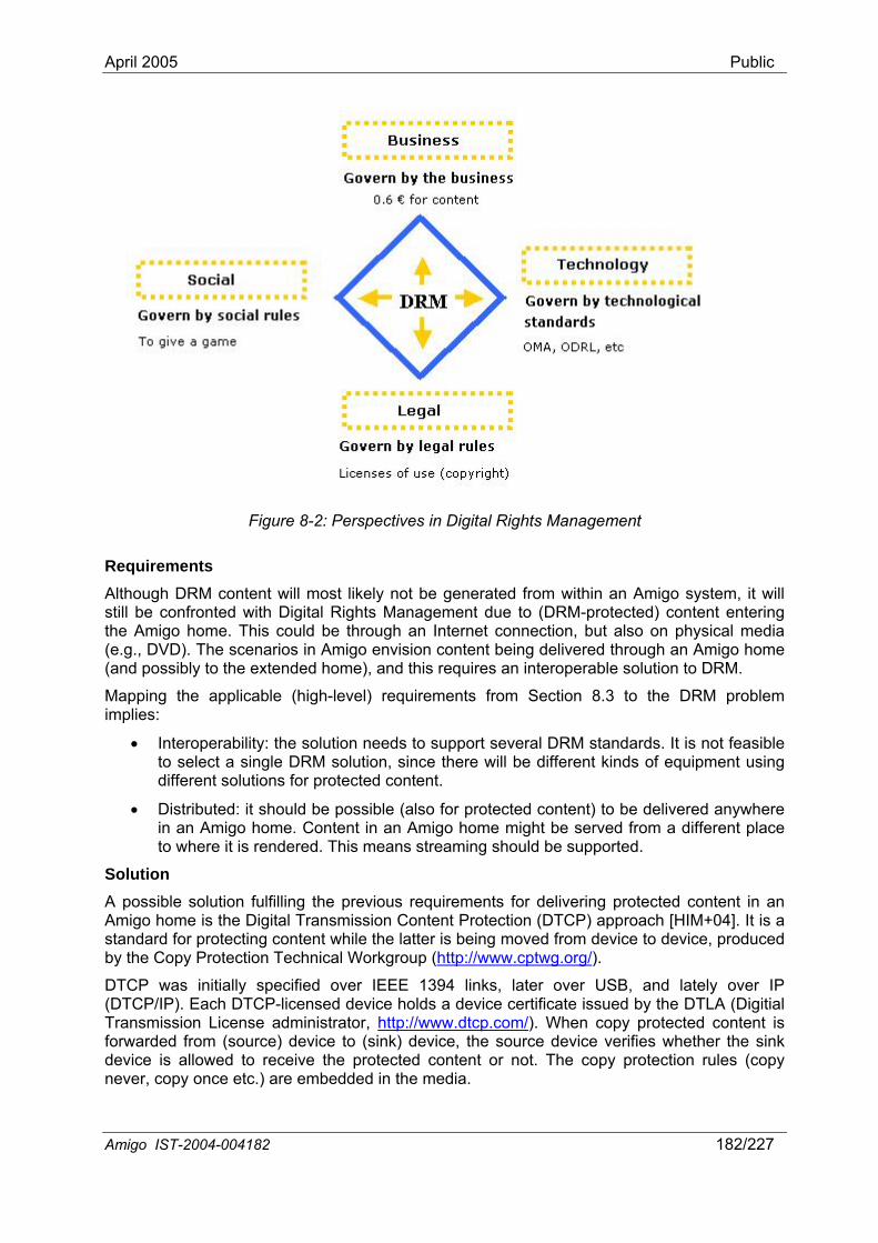
April 2005 Public
Figure 8-2: Perspectives in Digital Rights Management
Requirements Although DRM content will most likely not be generated from within an Amigo system, it will
le solution to DRM.
stributed: it should be possible (also for protected content) to be delivered anywhere
possible solution fulfilling the previous requirements for delivering protected content in an Amigo home is the Digital Transmission Content Protection (DTCP) approach [HIM+04]. It is a standard for protecting content while the latter is being moved from device to device, produced by the Copy Protection Technical Workgroup (http://www.cptwg.org/
still be confronted with Digital Rights Management due to (DRM-protected) content entering the Amigo home. This could be through an Internet connection, but also on physical media (e.g., DVD). The scenarios in Amigo envision content being delivered through an Amigo home (and possibly to the extended home), and this requires an interoperab
Mapping the applicable (high-level) requirements from Section 8.3 to the DRM problem implies:
• Interoperability: the solution needs to support several DRM standards. It is not feasible to select a single DRM solution, since there will be different kinds of equipment using different solutions for protected content.
• Diin an Amigo home. Content in an Amigo home might be served from a different place to where it is rendered. This means streaming should be supported.
Solution A
).
DTCP was initially specified over IEEE 1394 links, later over USB, and lately over IP (DTCP/IP). Each DTCP-licensed device holds a device certificate issued by the DTLA (Digitial Transmission License administrator, http://www.dtcp.com/). When copy protected content is forwarded from (source) device to (sink) device, the source device verifies whether the sink device is allowed to receive the protected content or not. The copy protection rules (copy never, copy once etc.) are embedded in the media.
Amigo IST-2004-004182 182/227
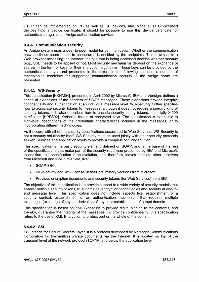
April 2005 Public
DTCP can be implemented on PC as well as CE devices, and, since all DTCP-licensed devices hold a device certificate, it should be possible to use this device certificate for authentication against an Amigo authentication service.
8.4.4 Communication security An Amigo system uses a peer-to-peer model for communication. Whether the communication between these peers needs to be secured is decided by the endpoints. This is similar to a Web browser accessing the Internet: the site that is being accessed decides whether security (e.g., SSL) needs to be applied or not. Most security mechanisms depend on the exchange of secrets in the form of keys for their encryption algorithms. These keys can be provided by the authentication server and presented in the token. In the following sections, a number of technologies candidate for supporting communication security in the Amigo home are presented.
8.4.4.1 WS-Security This specification [NKHM04], presented in April 2002 by Microsoft, IBM and Verisign, defines a series of extensions of the headers of SOAP messages. These extensions provide integrity, confidentiality and authentication at an individual message level. WS-Security further specifies
ic kind of lly X.509
security protocols te security solution.
curity element, defined on SOAP, and is the base of the rest urity road map presented by IBM and Microsoft.
olution, and, therefore, leaves obsolete other initiatives
, in their preliminary versions from Microsoft;
ity tokens (for Web Services) from IBM.
e de variety of security models that a ns, trust domains, encryption technologies and security at end-to-
ecification does not include aspects like: establishment of a
how to associate security tokens to messages, although it does not require a specifsecurity tokens. It is also described how to encode security binary tokens, especiacertificates [HPFS02], Kerberos tickets or encrypted keys. The specification is extensible to high-level descriptions of the credentials characteristics included in the messages, or to incorporating different technologies.
As it occurs with all of the security specifications associated to Web Services, WS-Security is not a security solution by itself. WS-Security must be used jointly with other at Web Services and application levels to provide a comple
This specification is the basic seof the specifications that make part of the secIn addition, this specification is an evfrom Microsoft and IBM in this field, like:
• SOAP-SEC;
• WS-Security and WS-License
• Previous encryption documents and secur
ecification is to provide support to a wiTh objective of this spen ble: multiple security tokeend message level. This spsecurity context, establishment of an authentication mechanism that requires multiple exchanges (exchange of keys or derivation of keys), or establishment of a trust domain.
This specification is based on XML Signature to provide digital signing to the contents, and thereby, guarantee the integrity of the messages. To provide confidentiality, this specification refers to the use of XML Encryption to protect part or the whole of the content.
8.4.4.2 SSL SSL stands for Secure Sockets Layer. It is a protocol developed by Netscape Communications Corporation for transmitting private documents via the Internet. It is located on top of the transport level of the network protocol (TCP/IP) and below the application level.
Amigo IST-2004-004182 183/227
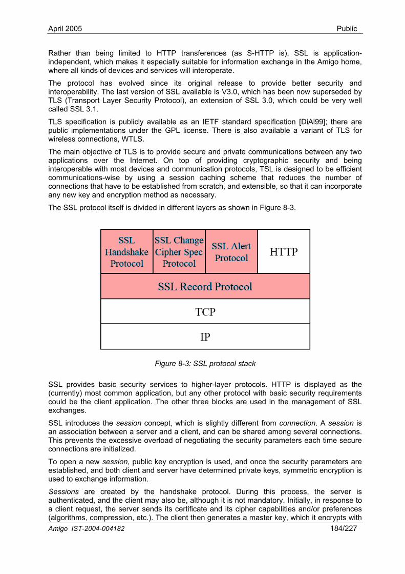
April 2005 Public
Rather than being limited to HTTP transferences (as S-HTTP is), SSL is application-independent, which makes it especially suitable for information exchange in the Amigo home, where all kinds of devices and services will interoperate.
The protocol has evolved since its original release to provide better security and interoperability. The last version of SSL available is V3.0, which has been now superseded by TLS (Transport Layer Security Protocol), an extension of SSL 3.0, which could be very well called SSL 3.1.
TLS specification is publicly available as an IETF standard specification [DiAl99]; there are public implementations under the GPL license. There is also available a variant of TLS for wireless connections, WTLS.
The main objective of TLS is to provide secure and private communications between any two applications over the Internet. On top of providing cryptographic security and being interoperable with most devices and communication protocols, TSL is designed to be efficient communications-wise by using a session caching scheme that reduces the number of connections that have to be established from scratch, and extensible, so that it can incorporate any new key and encryption method as necessary.
The SSL protocol itself is divided in different layers as shown in Figure 8-3.
Figure 8-3: SSL protocol stack
SSL provides basic security services to higher-layer protocols. HTTP is displayed as the (currently) most common application, but any other protocol with basic security requirements could be the client application. The other three blocks are used in the management of SSL exchanges.
SSL introduces the session concept, which is slightly different from connection. A session is an association between a server and a client, and can be shared among several connections. This prevents the excessive overload of negotiating the security parameters each time secure connections are initialized.
To open a new session, public key encryption is used, and once the security parameters are established, and both client and server have determined private keys, symmetric encryption is used to exchange information.
Sessions are created by the handshake protocol. During this process, the server is authenticated, and the client may also be, although it is not mandatory. Initially, in response to a client request, the server sends its certificate and its cipher capabilities and/or preferences (algorithms, compression, etc.). The client then generates a master key, which it encrypts with Amigo IST-2004-004182 184/227
April 2005 Public
Amigo IS 004-004182 185/227 T-2
the server’s public key, and transmits the encrypted master key to the server. If client authentication is required, it is then
The server and client exchange several randomly ge wi heir respective and private keys, so that they finally share the same master key, which they will use to generate
Once they have agreed on the keys and algorithms to use, and necessa both ends of com nication d master key they have agreed upon. To g , S se mac gh several states to keSpec Protocol. Of the several states that the p , one state is set as is o a the messages is issued, th pendiset.
Exchange o cure data is done through the SSL Record Protocol. The application data is encrypted with the Cipher specification set during the hprovides co entiality of the data exchanged. To assure message integrity, a MAC is appended to ck of data, in the SSL header. We may in Figure 8-4.
Figure 8-4: n
As previously mentioned, the standard is very open, an llow sever compressio , encryption and hashing algorithms. The compression alg in the protoco specification, and any or no compression encrypting, several different secure algorithms can be used,is provided.
The packet structure de
that the clien
n keys for the sessio
mueys
hereChange Cipher Spec messages
state replace
t certificate is sent.
erive the session key from the s at is
rotocol has, pending
s the
nerated bit
e state, and may flip throu purpose of the SSL Cha
when the session is establishede, which is set ready to
state and a new
s, encoded
been authenticated (if
th t
state is
the symmetric encryptio
ry),
ep the communication secure. Tha
state when one of the
n.
hinsole
stat
thenera
. B
pending
e
e
te k
ut t
SL u
als
the
current
nge Cipher
substitute
ng
currentcurrent
SSL data encapsulatio
d it a
can be used. For ha and suppor
picted in F
s for orithm is not
t for future e
igure 8-5.
al different defined shing andxtensions
nl
of an SSL Record message has the
is sent. Once one of these
f se
nfidandshake or later changes, which
each blo see the schema of the process
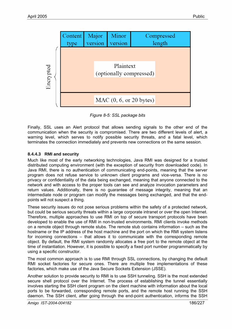
April 2005 Public
A go IST-2004-004182 186/227 mi
Figure 8-5: SSL package bits
Finally, SSL uses an Alert protocol that allows sending signals to re two different levels of alert, a
hreats, and ely and prevents new connections on the same session.
chnologies, Java RMI was or a trusted distr e (with the exception of security from downloaded code). In Java I, there is no authentication of communi d-points, meaning that the server program does not refuse service to unknown client programs and vice-versa. There is no priva being exchanged, meaning that anyone connected to the network and with access to the proper tools can see and analyze invocation parameters and return values. Additionally, there is no guarantee of message integrity, meaning that an intermediate node or program can modify the messages being excha d, and that the end-points will not su t a thing.
These security issues do not pose serious problems within the safety o cted network, but could be serious security threats within a large corporate intranet or o er the open Internet. Therefore, multiple approaches to use RMI on top of secure transpor have been developed to enable the use of RMI in non-trusted environments. RMI
gh remote stubs. The remote stub contains information – such as the system listens
g connections – that allows it to communicate with the efault, the RMI system randomly allo ject at the ntiation. However, it is possible to specify a fixed port number programmatically by
cific constructor.
roach is to use RMI through SSL connections, RMI socket factories for secure ones. There are multiple free implementations of these
ories, which make use of the Java Secure Sockets Extension (JSSE).
Another solution to provide security to RMI is to use SSH tunneling. SSH is the most extended secure shell protocol over the Internet. The process of establishing the tunnel essentially involves starting the SSH client program on the client machine with information about the local
s to be forwarded, corresponding remote ports, and the remote host running the SSH g through the end-point authentica
nge
f a protev
t protocols clients invoke methods
corresponding remotee remote ob
by changing the default
spec
on a remote object throuhostname or the IP address of the host machine and the port on which the RMIfor incominobject. By dtime of instausing a spe
The most common app
cates a free port to th
fact
portdaemon. The SSH client, after goin tion, informs the SSH
the other end of thecommunication when the security is compromised. There awarning level, which serves to notify possible security tterm
a fatal level, whichinates the connection immediat
8.4.4.3 RMI and security Much like most of the early networking te designed f
ibut RM
d computing environment cating en
cy or confidentiality of the data
April 2005 Public
A go IST-2004-004182 187/227 mi
daemon about remote connection addresses and starts listening for incoming connections on the local ports.
Whenever this SSH client gets a connection request on a port that has been forwarded for tunneling, it accepts the connection and informs the SSH daemon, which, in turn, establishes
with the corresponding r address. r that, a exchange between the he server program flows through the SSH client and the SSH daemon, and is
ity.
vironment. It is position
Amigo system.
Security is not enforced on components, there may and will be components in an Amigo syst t do not need to embed security, as their operation or implication on wrong usage doe t compromise th the home or other components.
The figuration is ke e home). It does not ge about the used technologies, nor does it require extensive analysis
f configuration
e stateless,
istributed implementation and avoiding a single point of failure in the network.
The elaboration of the of our future work in Amigo; it will specifically be addressed in Task 3.5 on security and privacy of Work package WP3, and Task 4.3 on p curity issues
connection client and tencrypted to ensure privacy and me
8.5 DiscussiThe Amigo a networked home enenable heterogeneous networks and devices to participate;that it still allows legacy devices to
em
ssage integr
hit
participat
ote
ecture
Afte
in this
ll d
is not restrictive, in
ata
on security and privacy arc outlined
ed at the middleware and application level to
e a
chapter is specifica
yethe services
lly designed for
the sensend use all t they would in a non-
em hats no e security of
con pt relatively simple and domain-specific (to threquire specific knowledin ca
The security-related components (authentication and authorization) arthat they do not require maintenance and exchence allowing a d
se o changes.
in the sense hange/verification during service executing,
Amigo security and privacy architecture is part
rivacy and personal se of Work package WP4.

April 2005 Public
A 182 189/227 migo IST-2004-004
9 Support of user/technical requirements within the Amigo architecture
ter, we first (Section 9.1) deduct the tech ments on the Amigo r requirements (see Deliverable D1.2 [Amigo-
ser require prioritized o
ry to deliver the best
view (e.g., because of
Amig bstract architecture, which has been elaborated in the previous chapters. This should show the support of the technical requirements by the Amigo abstract architecture. We finally state r conclusions in Section 9.3.
9.1 cting techn iremen e user requirements we summariz dentified and their priority in Table
where the user requirements apply to: which application domains narios), which in t user services, and/or if the user
he system in general. If it applies to the system in general, we will find r that this usually leads to technical requirements in the middleware.
In Ta 9-1, the application domains are abbreviated as:
• D Home Care and Safety • D2: Home Information and Entertainment • D3: Extended Home Environment
And inte ent user services are abbreviated as (as explained in DoW description of WP4):
• S1: Context collection, a nd ion • S2: User modeling and p• S3: Awareness and notification • S4: Content provision, selection and retrieval • S5: User interface • S6: S y and priv
ble 9-1, the technical re coming from the user ents d. This the result volving not only WP1
work was continued and refined in smaller groups later. In
ments on the middleware, on the ligen
tions (W As you c l tech l requ ng to more than one user requirement.
nt to realize here that especially the general user requirements, including the very obvious, will lead to technical requirements for the middleware. Even though some of these general user requirements seem very obvious, the Amigo system will not be accepted and valued by the end-user if these requirements are not met. This is why we have given them the
est priority of all (highest priority = 0). Prioritizing of user requirements is necessary, as
middleware
design and implementa
In this chamiddleware coming from analyzing tD1.2], volume I for the summarized prioritizeddeducted frstudies. Toffs both in architecture,possible result for the end-user. Some technical requirements cannot be deducted from a user point ofother stakeh
We then (Section 9.2)
p
om the user requirements are also his is n
nical requir
ments). The technica b
s or require
e
es not exist
ments), but come from
the middleware with the
he WP1 use
lly the idea
main-specific standard
u
l system architecture do
u
l ret fro
quirementsm the user and trade-
ased on the utpuecessary, as usua
dossed in Chapt
tion phase are necessa
er 10 and are not addressed in this chapter.
irements deducted for
olders. They are discu
match the technical reqo a
ou
Dedu ical requ ts from thFrom9-1. We have analyzed(coming from the three Amigo scerequirement applies to tout l
D1.2, e the user requirements that were i
telligen
ate
ble
1:
the llig
ecurit
st column of Ta
ut also WP2-7 me
t user services, and proprietary technical requirements only being valid for one of thee applica
ggregation arofiling
acy
is mbers. In this workshop, the user requirements were
P5-7).
predict
quirements of a two-day workshop in
an see
In the lamentioned are deductemembers, binto technical requirements. This this process, a split was made between technical requireintelproto
requirem
translated
irements belotyp severa nica
It is importa
high

April 2005 Public
A 182 190/227 migo IST-2004-004
usually the ideal system architecture does not exist and trade-offs both in architecture, design and implementation ph eliver the best possible result fo e en ser. ase are necessary to d r th d-u
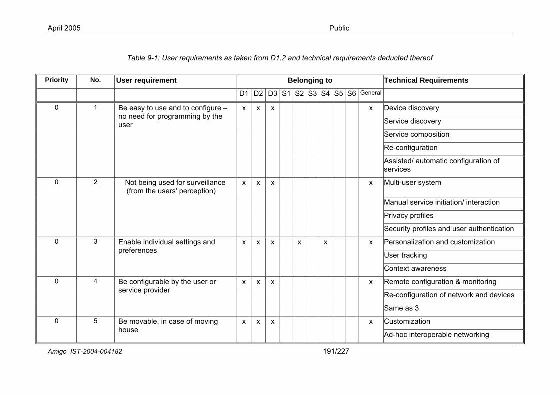
April 2005 Public
Table 9-1: User requirements as taken from D1.2 equirements d
Priority No. B lo gin to ents
and technical r educted thereof
User requirement e n g Technical Requirem
D1 D2 D3 S1 S2 S3 S4 S5 S6 General
Device discovery
Service discovery
Service composition
Re-configuration
0 1 Be easy to use and to configure – no need for programming by the
x x x x
uration of
user
Assisted/ automatic configservices
Multi-user system
Manual service initiation/ interaction
Privacy profiles
0 2 perception)
x x x x
ser authentication
Not being used for surveillance (from the users'
Security profiles and u
Personalization and customization
User tracking
0 Enable individual settings and preferences
x x x x x x 3
Context awareness
Remote configuration & monitoring
Re-configuration of network and devices
0 Be configurable by the user or service provider
x x x x 4
Same as 3
Customization 0 5 x x x x
Ad-hoc interoperable networking
Be movable, in case of moving house
Amigo IST-2004-004182 191/227
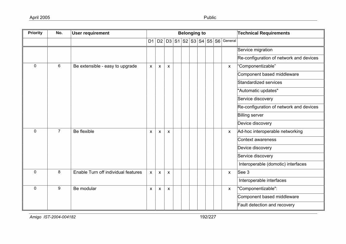
Public
igo IST-2004-004182 192/227
y No. User requirement Belonging to ical ReTechn quirements D1 D3 S1 S2 S3 S5 S6 D2 S4 General
Se e m arvic igr tion
Re nfig ti ces -co ura on of network and devi
“Compon zenti able”
Component based middleware
Standard ized services
"Automat pic u dates"
Service d visco ery
Re-config ti ces ura on of network and devi
Billing se rver
0 6 Be extensible - easy to upgrade x x x x
De di vvice sco ery
Ad c in-ho teroperable networking
Co xt a ente war ness
Device di vsco ery
Service d visco ery
0 7 Be flexible x x x x
Interope erabl (domotic) interfaces
See 3 0 8 Enable Turn off individu x x x
pe e
al features x
Intero rabl interfaces
"Compon zenti able":
Compon aseent b d middleware
0 9 Be modular x x x
etection aFault d
x
April 2005
Am
Priorit
nd recovery
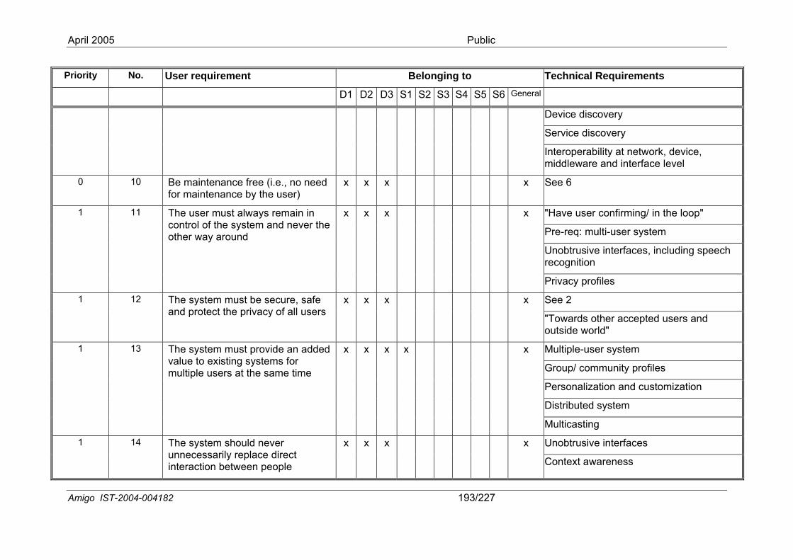
Public
ig 2 193/227 o IST-2004-00418
Priori r t Belonging to Technical Requirements ty No. Use requiremen D1 D2 S1 S2 S4 S5 D3 S3 S6 General
Device discovery
Service cove dis ry
Interoperability at network, device, middleware and interface level
0 10 Befor
m fre ., no neem by ser)
x x See aintenance aintenance
e (i.ethe u
d x x 6
"Have user conf ng/ in the looirmi p"
Pre-req: mult m i-user syste
Unobtrusive interfaces, including speech recognition
1 11 Thcooth
e u wa main in ntr te d never ter
x x ser must alol of the sys way around
ys rem an he
x x
Privacy profiles
See 2 1 12 The s b ureand p riv f al th and
rld
ystem mustrotect the p
e secacy o
, safe l users
x x x x
"Towards ooutside wo
er acce"
pted users
Multiple-user system
Group/ comm y prounit files
Personalization and customization
Distr syibuted stem
1 13 The sys pr e an a
multiple the e tim
Multicasting
tem mustvalue to existing systems for
users at
ovid
sam
dded
e
x x x x x
Unobtrusive interfaces 1 14 The system should never unnecessarily replace direct
on betweinteracti en ple
x x
Context awaren
x
peo
April 2005
Am
x
ess
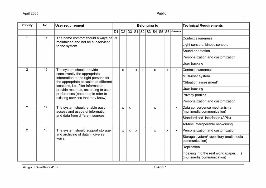
Public
igo IST 27-2004-004182 194/2
Priority e ic No. User requirem nt Belonging to Techn al Requirements 2 D1 D D3 S1 S2 S3 S4 S5 S6 General
Context awareness
Light sensors, kinetic sensors
Sound adaptation
Personalization and customization
1 mfd
ac
15 The homemaintaineto the syst
cod anem
ort shouldnot be su
albse
wayrvi
s be ent
x
User tr king
Context awareness
Multi-user system
"Situation assessment"
User tracking
Privacy profiles
2 m sholy the to thriate .e., fil
sumes, a ses (note o rvices th )
x
al
16 The systeconcurrentinformationthe approplocations, iprovide repreferenceexisting se
uld provid approprie right peoccasion ter inform
ccordipeopleat the
e ate rsoat dationg refy kn
ns iffen,
to uer tow
for rent
r
x x x x x
Person ization and customization
Da(m
ta conultime
vergence mechanisms dia communication)
Standardized interfaces (APIs)
2 m shouldd usage om
x
-hoc i
17 The systeaccess anand data fr
enabof info
different sources.
le easy rmation
x x x
Ad nteroperable networking
Personal ization and customization
Stoco
rage memmun
system/ repository (multiication)
dia
Replication
2 m should rt storaging of da iverse
x x
exing r, ultime
x x e suppota in d
18 The systeand archivways.
April 2005
Am
x x
Ind(m
into the real world (papedia communication)
…)
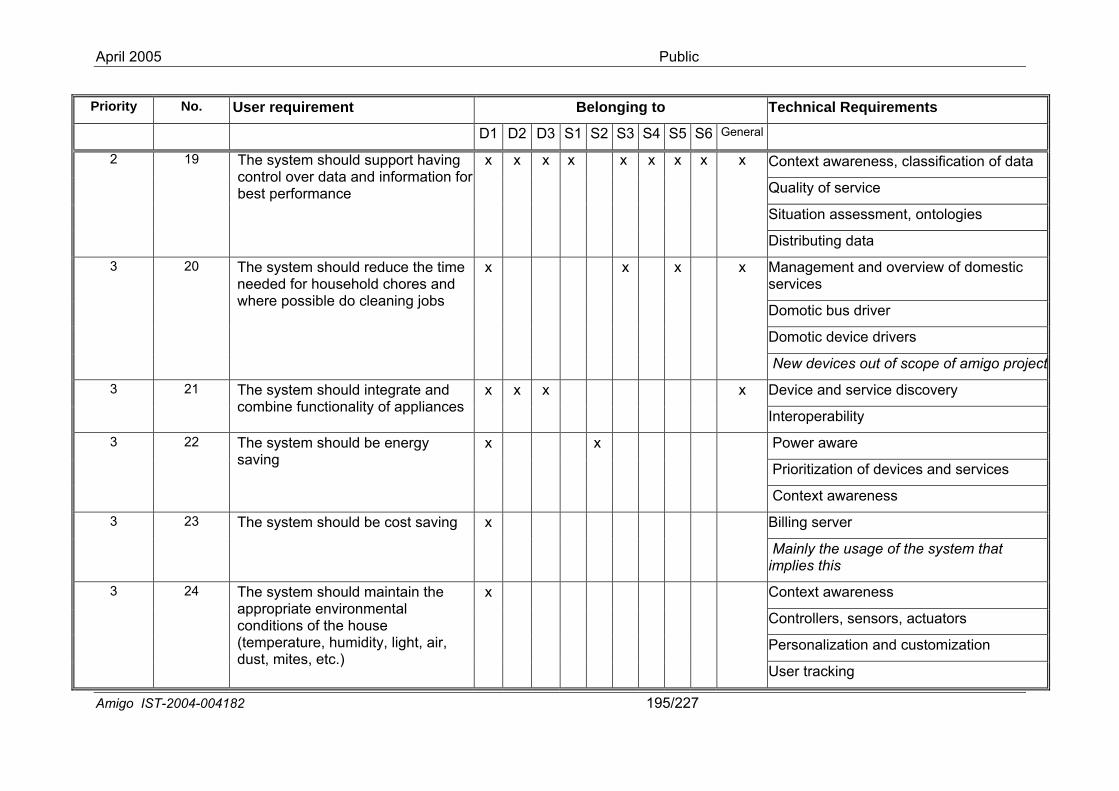
Public
migo IST-2004-00 954182 1 /227
Pr No eqiority . User requirement Belonging to Technical R uirements 2 al D1 D D3 S1 S2 S3 S4 S5 S6 Gener
Context aware a ness, classification of dat
Quality of service
Situation assessment, ontologies
2 19 sud
x
at
The system shocontrol over datbest performanc
uld a ane
pport having information for
x x x x x x x x
Distributing d a
Manageservices
ment and overview of domestic
Domotic bus driver
Domotic device drivers
3 20 reldle
s out projec
The system shoneeded for houswhere possible
uld ehodo c
duce the time chores and aning jobs
x x x x
New device of scope of amigo t
Device and service discovery 3 21 uld intnality
x x
ability
The system shocombine functio
egrate and of appliances
x x
Interoper
Power aware
Prioritization of d evices and services
3 22 uld be
awarene
The system shosaving
energy x x
Context ss
Billing server 3 23 uld be
e usageis
The system sho cost saving x
Mainly thimplies th
of the system that
Context awareness
Controllers, sensors, actuators
Personalization and customization
3 24 uld mainronment house midity, li
g
The system shoappropriate enviconditions of the(temperature, hudust, mites, etc.)
April 2005
A
tain the al
ght, air,
x
User trackin
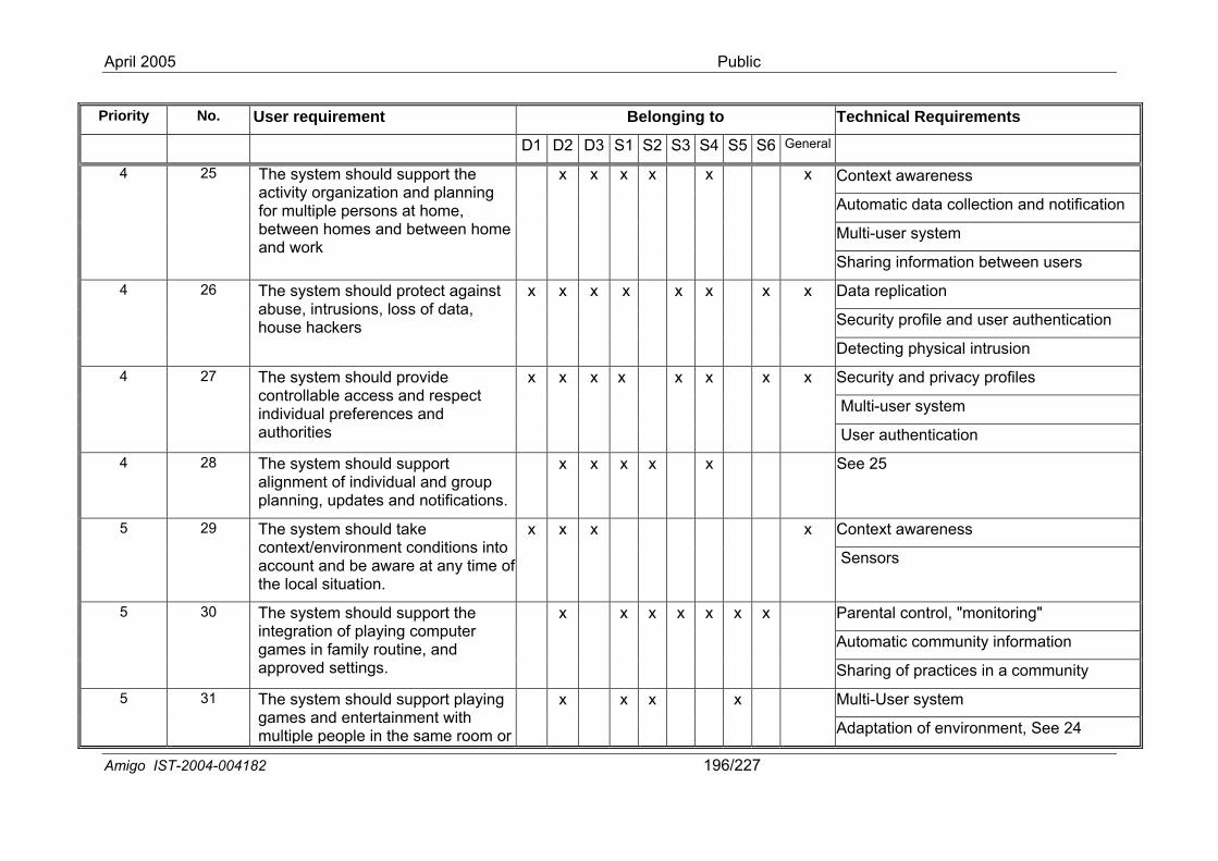
Public
migo IST-2004-0 1904182 6/227
Pri o. ng tsority N User requirement Belongi to Technical Requiremen D1 D2 D3 S1 S2 S3 S4 S5 S6 General
Context awareness
Automatic data collection and notification
Multi-user system
4 25
we
The system shactivity organizfor multiple perbetween homeand work
ould support the ation and planning sons at home, s and between home
x x x x x x
Sharing information bet en users
Data replication
Security profile and user authentication
4 26
sion
The system shabuse, intrusiohouse hackers
ould protect againstns, loss of data,
x x x x x x x x
Detecting physical intru
Security and privacy profiles
Multi-user system
4 27
re
x x The system shcontrollable acindividual prefeauthorities
ould provide cess and respect
nces and
x x x x x x
User authentication
4 28 oudivte s.
x The system shalignment of inplanning, upda
ld support idual and group
s and notification
x x x x See 25
Context awareness 5 29 oum to
e a ofon
The system shcontext/environaccount and bthe local situati
ld take ent conditions inware at any time .
x x x x
Sensors
Parental control, "monitoring"
Automatic community information
5 30 oulay rng
x x
in a com
The system shintegration of pgames in familapproved setti
ld support the ying computer outine, and s.
x x x x x
Sharing of practices munity
Multi-User system 5 31 ou g er
ld support playintainment with
The system shgames and entmultiple people in or
x
nment, S
April 2005
A
the same room
x x x
Adaptation of enviro ee 24
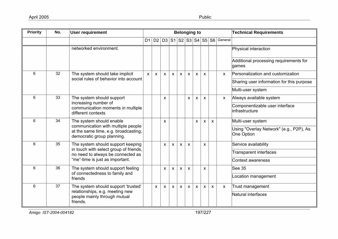
Public
igo IST-2004-0041 82 197/227
Priority No. Us equirem lo er r ent Be nging to Technical Requirements S2 ner D1 D2 D3 S1 S3 S4 S5 S6 Ge al
Physical interaction
ir
networked environment.
Additional processing games
requ ements for
Personalization and customization
Sharing user information for e this purpos
6 yst pli ru or into a
x x 32 The ssocial
em shoulles of beh
d taavi
ke im cit ccount
x x x x x x x
Multi-user system
Always available system 6 yst pport sinun nts in mulnt
x
erfaci
33 The sincreacommdiffere
em shoulg numbeication mcontexts
d sur of ome tiple
x x x x
Componentizable usenfrastructure
r int e
Multi-user system 6 yst able un ultiple pesa broadcas
cra nning.
e.g.,
34 The scommat the demo
em shoulication wime time, tic group
d enth me.g.pla
ople ting,
x x x x
Using "Overlay NetwoOne Option
rk" ( P2P), As
Service availability
Transparent interfaces
6 yst pport keech oup of frieed connecteim portant.
x x 35 The sin touno ne“me”-t
em shoulwith seleto alwayse is just a
d suct gr be s im
ping nds, d as
x x x
Context awareness
See 35 6 yst pport feeline to family and s
x x 36 The sof confriend
em shoulctedness
d su ng x x x
Location management
Trust management 6 yst d support ‘trusns meeting new
e m ough mutual s.
x x x 37 The srelatiopeoplfriend
em shoulhips, e.g.ainly thr
ted’ x x x x x x
April 2005
Am
Natural interfaces
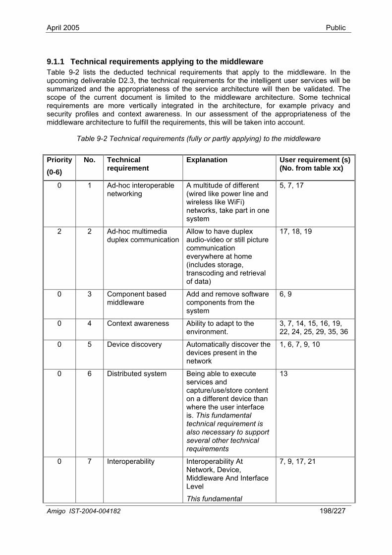
April 2005 Public
9.1 o the middleware
upcsumscoreqsec e
(0-6
.1 Technical requirements applying tTable 9-2 lists the deducted technical requirements that apply to the middleware. In the
oming deliverable D2.3, the technical requirements for the intelligent user services will be marized and the appropriateness of the service architecture will then be validated. The
pe of the current document is limited to the middleware architecture. Some technical uirements are more vertically integrated in the architecture, for example privacy and urity profiles and context awareness. In our assessment of the appropriateness of th
middleware architecture to fulfill the requirements, this will be taken into account.
Table 9-2 Technical requirements (fully or partly applying) to the middleware
Priority )
No. Technical requirement
Explanation User requirement (s) (No. from table xx)
0 1 Ad-hoc interoperable A multitude of different networking (wired like power line and
wireless like WiFi) networks, take part in one system
5, 7, 17
2 2 Ad-hoc multimedia duplex communication
Allow to have duplex audio-video or still picture communication
17, 18, 19
everywhere at home (includes storage, transcoding and retrieval of data)
0 3 Component based middleware components from the
system
Add and remove software 6, 9
0 4 Context awareness Ability to adapt to the environment.
3, 7, 14, 15, 16, 19, 22, 24, 25, 29, 35, 36
0 5 Device discovery Automatically discover the 1, 6, 7, 9, 10 devices present in the network
0 6 Distributed system Being able to execute services and capture/use/store content on a different device than where the user interface is. This fundamental technical requirement is also necessary to support several other technical requirements
13
0 7 Interoperability Interoperability At Network, Device, Middleware And Interface Level
This fundamental
7, 9, 17, 21
Amigo IST-2004-004182 198/227
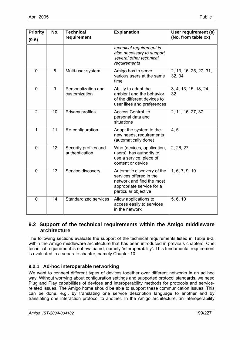
April 2005 Public
Priority (0-6)
No. Technical requirement
Explanation User re(No. fro
quirement (s) m table xx)
technical requirement is also necessary to support several other technical requirements
0 8 Multi-user system Amigo has to serve various users at the same time
2, 13, 16, 25, 27, 31, 32, 34
0 9 Personalization and customization
Ability to adapt the ambient and the behavior of the different devices to user likes and preferences
3, 4, 13, 15, 18, 24, 32
2 10 Privacy profiles Access Control to 2, 11, 16, 27, 37 personal data and situations
1 11 Re-configuration Adapt the system to the new needs, requirements (automatically done)
4, 5
0 12 Security profiles and authentication
Who (devices, application, users) has authority to use a service, piece of content or d
2, 26, 27
evice
0 13 Service discovery Automatic discovery of the services offered in the
appropriate particular
1, 6, 7, 9, 10
network and find the most service for a
objective
0 14 Standardized services Allow applications to access easily to services in the network
5, 6, 10
9.2 Support ofarchitectur
The following sectio 2, o m
uiremeted in a se
oc int connec an ad hoc
hout worryiapahe
ne, e.g., b er and by one inte
the technical requirements within the Amigo middleware e ns evaluate the support of the technical requirements listed in Table 9-
within the Amigtechnical reqis evalua
iddleware architecture that has been introduced in previous chapters. One nt is not evaluated, namely ‘interoperability’. This fundamental requirement parate chapter, namely Chapter 10.
9.2.1 Ad-hWe want to
eroperable networking t different types of devices together over different networks in
way. WitPlug and Play crelated issues. Tcan be do
ng about configuration settings and supported protocol standards, we need bilities of devices and interoperability methods for protocols and service-
Amigo home should be able to support these communication issues. This y translating one service description language to anoth
translating raction protocol to another. In the Amigo architecture, an interoperability
Amigo IST-2004-004182 199/227
April 2005 Public
method with parsers onnects devices that use different protocols, o they can ‘talk’ with each other (see Chapters 3 and 5).
me content and services.
9.2.2 Ad-hoc multimediUs migo home expect to watch video and receive multimedia contents (audio, films,
hs, th
the corridor, thecontent; they shdistortions or inte
The Amigo middAmigo Multimedia Streaming Architecture (see Chapter 6). In this architecture, we are taking
asp Nod
Holder and the developing the dadaptation of spealso covered in the middleware, using transcoding techniqu
ideo sOne of the Ami roduce
relies on t orde
Digital Me Digital Me
ideo server capabilities will be fully covered in Amigo architecture with the Digital Media
and composers of protocols cs
In the example of a user walking through the Amigo home with his/her portable device, it should be possible that the user’s device is able to ‘talk’ with every other Amigo device, without necessarily using the same network type or protocol. A Jini device in the Amigo home shall be capable of interoperating with other devices, such as a UPnP device. Also, at higher levels like OSGi, applications should be capable to talk to devices using different protocols and communication hardware, while at application level the user does not notice any translation being done by the Amigo system and therefore works with a smooth system. The Amigo user does not have to worry about different standards and protocols anymore and can simply connect every Amigo device with another one and share the sa
a communication ers of the A
still photograpis. In addition
, etc.) everywhere in the house, regardless of where the source of this content ey do not want to worry about what kind of device (mobile phone, a screen in loudspeakers of the bathroom, etc.) they have chosen for displaying the ould be able to receive the data with an acceptable quality and without rferences (Quality of Service).
leware will cover all this issues with all the elements introduced with the
into accountIntermediate
ects like content distribution between different networks (solved with the e element), the QoS in multimedia communications (covered by the Policy QoS Manager), and are establishing source, sink and manager roles for ispatching of content (Media Server, Media Renderer and Control Point). The cific content features (e.g., change in resolution) to the device capabilities is
es.
9.2.2.1 V erver go home main objectives’ is that devices can share, store and rep
content andelements in
heir capabilities. To achieve this goal, Amigo exposes two types of r to offer these services:
dia Server (DMS), as presented in Section 6.3.1. dia Render (DMR), as presented in Section 6.3.2.
VServer (DMS). Its main functionalities will be to provide acquisition, publication, storage and sourcing capabilities of video contents.
9.2.2.2 Local database Dealing with multimedia content requires the management of large amounts of information. A local database will be integrated in Amigo architecture as a Digital Media Server. Its single function will be to store and provide content to other devices. For instance, a user wants to download some songs on his MP3 player or wants to watch a film on the TV. All these actions will request for content to the database. The local database will be located within the DMS architecture in the Heterogeneous Platform Layer in Content Storage (see Figure 6-14, §6.3.1). It will be a very important point inside the architecture for other devices to have a place to store multimedia information, for example a camera uploading photos to the database.
Amigo IST-2004-004182 200/227
April 2005 Public
9.2.2.3 External content server External multimedia content comes from a lot of different sources (films, audio…) with different protocols. It is necessary to have a point where all this content is checked and managed to be
very diverse and needs a tion will be treated for each
pes of external sources and dispatching content in th
9.2.3 The eobj -service
9.2.4 reness Ser eAmigo Contex
ranging from physical sensors to Internet applications, combine these pieces of information to Amigo services so as
eading to provide context-aware
d registry to discover various kinds of
ser devicesservice discovery, the network can be searched for discoverable devices.
9.2.6 Theorie devcomsystem sure th infrastr The distributed system’s openness is supported even further by elements
management.
d their guests at the same time. without interfering with each ffectively supports multiple
able to circulate them in the network. Multimedia content is specialized treatment in each case. Different formats of informaone in a specific way. External content server will be supported by the Amigo Architecture within Digital Media Server in the middleware layer within “Content Management”. In this layer, programs will exist, capable of managing different ty
e home network.
Component-based middleware s rvice-oriented architecture proposed for the Amigo system builds upon results from
ect based and component-based middleware technologies. Both the middleware and the s on top are fully composable and work with mobile components (see Chapter 2).
Context-awavic description in Amigo is complemented with context information. Context information in
is collected and organized by a specialized context management middleware service. t management mechanisms span all three layers of the Amigo architecture (see
Chapter 3 and Figure 3-2).
The role of the Amigo Context Manager is to acquire information coming from various sources,
into "context information", and make this context information available to enable these services to become context-aware, further lservice discovery, context-aware service composition etc. Amigo applications may then be context-aware, as they can get contextual information from the context manager and use it for their specific application purposes.
9.2.5 Device discovery Device Discovery is the process of finding a device present in the network. The Amigo interoperable service discovery is based on various service discovery protocols anstandards. Thus, the Amigo middleware integrates mechanisms
vices. Most of these protocols (e.g., UPnP) allow the discovery of not only services but also (either directly or indirectly via hosted services). Then, using Amigo interoperable
Distributed system Amigo architecture is distributed by nature, and is more specifically based on the service-nted architecture style (see Chapter 2). Service-oriented computing aims at theelopment of highly autonomous, loosely coupled systems that are able to communicate, pose and evolve in an open, dynamic and heterogeneous environment. The distributed
approach is supported further by enforcing autonomy for separate devices, makingat components can appear, disappear and evolve, being able to handle heterogeneousuctures etc.
like service discovery, semantic-based service interoperability and context
9.2.7 Multi-user system The Amigo system has to serve all people in a family anMultiple users should be able to use the system at the same time, other. The extent to which the Amigo networked home system e
Amigo IST-2004-004182 201/227
April 2005 Public
use instant that response times are fast enough when multiple people are sending requests. The QoS as wel from m
9.2.8 Services and devices behavior in Amigo will beuser profiles and context situations (see Chapter 3). This feature will in particular be covered in
ter 4). This capability
ded. versation of the composite
ser
The Am wareness for effe adaptiv ddressed at the leve
9.2.9 al information from
The co igo users can wor
Privac disc ser guest d identitie these identifiers, e.g., by using IDs for identities
apped to descriptive names by
ue to the fact that any user can relatively simply distcontrolthe pro gement of (digital) rights on contents. DRM technology in A
9.2Automamiddleware (see Chapters 3-5): enhanced service discovery and ad hoc composition of services. Such a capability further assumes support for self-configuration at the network level.
rs depends on how the system is implemented, to make sure that services can beiated multiple times to serve multiple people at the same time and also to make sure
l as the user interface system has in particular to support possible contradictory requestsultiple users.
Personalization and customization not fixed but have to be adaptable to different
the middleware with the ad-hoc composition of services (see Chaptranslates into the integration on the fly of a set of services to realize a composite service described in the form of an abstract workflow. The objective is to allow this composite service to be executed by integrating available environment's services. A description of this service is available as an abstract OWL-S conversation. In order to select the set of services that are suitable to be integrated, and to integrate this set of services, a matching algorithm is neeThe matching algorithm enables reconstructing the abstract con
vice using fragments from the conversations of the environment’s services.
igo ad hoc composition of services is to be further coupled with context-active personalization and customization, which will be investigated in WP3 Task 3.6 on
e service composition. Also, personalization and customization will be al of intelligent user services.
Privacy profiles Privacy is a broad term concerned with all kinds of mechanisms to conceunauthorized access. With respect to the Amigo system, privacy protection involves (see Chapter 8):
- Privacy protection of identifiable information like identities.
- Protection of content delivered to the home like DRM protected content.
mbination of these 2 items in Amigo can form privacy profiles where Amk with in the Amigo home.
y protection of identities: In an Amigo system, identification-, registration- andovery services all depend on and exchange identities of resources (users, devices and
vices). Without protection, any device that is granted access to an Amigo system (includingevices) is able to see these identities and implicitly track them. Privacy protection ofs can be achieved by anonymizing
instead of descriptive values. If necessary, these IDs can be ma service that has its access controlled. Protection of content: Nowadays, the rights to access content are enforced by the content owner (e.g., buy a song) but often the same content can be found (unprotected) in the Internet, PCs, mobile devices, etc. This is mainly d
ribute content once it is on his/her device. This further implies that the content owner loses on the use on that content. The DRM technology’s objective is to provide an answer to blem associated with the mana
migo enables controlled distribution and avoids fraudulent usage of content (see §8.4.3.2).
.10 Re-configuration tic configuration and re-configuration build on a number of functionalities of the Amigo
Amigo IST-2004-004182 202/227
April 2005 Public
Howand wiprototy aken within Task 3.9 ded
the networked home system using a Role Based Access Con
9.2ServiceAmigo nd use services that reside in nodes whose concrete middleware architecture is also based on the Amigo
to enhanced service
ility requirements within the Amigo environment. This is further complemented with the Amigo interoperability methods enabling application- and middleware-layer
5).
rking, the Amigo middleware proposes a middleware-layer interoperability method, detailed in Chapter 5, with parsers and composers of
t they can ‘talk’ with each
lications can be context aware applications because they can get contextual information from the Amigo “context manager” purcominfo
ever, integrated support for (re-)configuration in the Amigo system is still to be devised ll be further investigated as part of WP3 work on the Amigo middleware refinement and pe implementation. Such an effort will in particular be undert
icated to mobility management.
9.2.11 Security profiles and authentication The proposed architecture in Amigo for privacy and security is specifically targeting the requirements of a networked home system (see Chapter 8). We want to pursue the idea of the Amigo home to be working with a Trusted Domain approach. Base building blocks for the security and privacy architecture are two middleware services: authentication and authorization. Authentication handles the processes of verifying an identity, while authorization handles the access control for that identity. The authentication solution is based on the Kerberos system principle (with identities for users, devices and service), the authorization processes is specifically designed for
trol (RBAC) approach.
.12 Service discovery Discovery is the process of finding services with a given capability. The Abstract Discovery Architecture ensures that the services using it can discover a
Abstract architecture (see Chapter 3). The service discovery is divided indiscovery for Amigo services (see §3.2.1.1) and interoperable service discovery that integrates various service discovery protocols (see Chapter 5).
9.2.13 Standardized services For enabling functional interoperability between Amigo services, it is needed to build and describe those using standardized mechanisms. The Service-Oriented Architecture proposed in Amigo with Web Services as its main representative, semantically enhanced by Semantic Web principles into Semantic Web Services, will partially cover the interoperability requirements within Amigo. OWL-S based modeling will in particular offer enhanced support to the interoperab
interoperability (see Chapters 3-
9.3 Conclusions The following conclusions can be drawn from the above assessment:
• For ad-hoc interoperable netwo
protocols to connect devices that use different protocols, so thaother.
• For ad-hoc multimedia duplex communication, the Amigo Multimedia Streaming Architecture was introduced in Chapter 6, which supports content distribution between different devices inside and outside the home.
• Amigo Appand use it for their specific application
poses (see Chapter 3). This manager collects information from various sources and bines these pieces of information into "context information"; it then makes this context rmation available to amigo services.
Amigo IST-2004-004182 203/227
April 2005 Public
• Themid
• Bot between themidPCwithpro
• Theserhighly autonomous, loosely coupled evolve in an open, dynamic and heterogeneous environment, like the networked home.
Theanddel
Personalization and customization is partly supported in the middleware with the ad-hoc
em. The high-level middleware architecture provides the basics to deliver automatic (re-)configuration but
large scale open e the Internet. This architecture will be further studied and extended in the se of this work package as well as in WP3 and WP4.
• its
service oriented architecture as chosen for Amigo is intrinsically a component-based dleware architecture (see Chapter 2).
h for device and service discovery, an extensive interoperability mechanism commonly used protocols within the Amigo domains, is described for the Amigo dleware architecture. This approach will support interoperability over the different CE, , mobile and domotic domains, while keeping backwards compatibility and compatibility non-Amigo devices in place (see Chapters 3-7). This is a huge advantage of the
posed Amigo middleware architecture, which is further assessed in the next chapter.
Amigo architecture is distributed by nature and is more specifically based on a vice-oriented architecture. Service-oriented computing aims at the development of
systems that are able to communicate, compose and
• actual support for a multi-user system is very much dependent on the further design implementation of the Amigo system. Support of QoS and other priority mechanisms
iver the possibility of making the Amigo system multi-user proof.
• composition of services introduced in Chapter 4, which has to be combined with context-awareness. Also, the actual personalization and customization of services is the topic of further study within the Amigo intelligent user services.
• There is a base approach considered to guarantee privacy within the Amigo system by anonymizing certain identifiers. However guaranteeing people’s privacy is clearly broader than the middleware architecture alone and its implementation is subject of further study within the service architecture.
• The possibility for automatic (re-)configuration of devices and services is highly dependent on the actual implementation chosen within the Amigo syst
does not necessary guarantee it.
• The proposed architecture for privacy, security and authentication works with a Trusted Domain approach and is specifically targeted at a networked home environment. It is highly suitable for this environment but cannot be extended to very networks liksecond pha
Standardized services are supported by the chosen middleware architecture, as part of support for interoperability.
Amigo IST-2004-004182 204/227
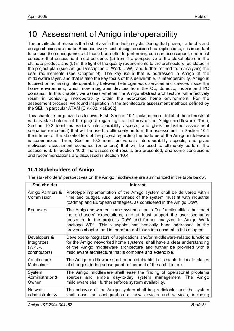
April 2005 Public
10 Assessment of Amigo interoperability The architectural phase is the first phase in the design cycle. During that phase, trade-offs and design choices are made. Because every such design decision has implications, it is important to assess the consequences of these trade-offs. In performing such an assessment, one must
ive of the stakeholders in the
(see Amigo Description of Work-DoW), and further refined from analyzing the nts (see Chapter 9). The key issue that is addressed in Amigo at the
er, and that is also the key focus of this deliverable, is interoperability. Amigo is foc home domainresult assess the SE
Thi various Section 10.2 identifies various interoperability aspects, and gives motivated assessment ce ) that will be used to ultimately perform the assessment. In Section 10.1
esults are presented, and some conclusions and recommendations are discussed in Section 10.4.
consider that assessment must be done: (a) from the perspectultimate product, and (b) in the light of the quality requirements to the architecture, as stated in the project plan user requirememiddleware lay
used on achieving interoperability between heterogeneous services and devices inside theenvironment, which now integrates devices from the CE, domotic, mobile and PCs. In this chapter, we assess whether the Amigo abstract architecture will effectively in achieving interoperability within the networked home environment. For thement process, we found inspiration in the architecture assessment methods defined byI, in particular ATAM [ClKK02, KaBa02].
s chapter is organized as follows. First, Section 10.1 looks in more detail at the interests of stakeholders of the project regarding the features of the Amigo middleware. Then,
s narios (or criteriathe interest of the stakeholders of the project regarding the features of the Amigo middleware is summarized. Then, Section 10.2 identifies various interoperability aspects, and gives motivated assessment scenarios (or criteria) that will be used to ultimately perform the assessment. In Section 10.3, the assessment r
10.1 Stakeholders of Amigo The stakeholders’ perspectives on the Amigo middleware are summarized in the table below.
Stakeholder Interest
Amigo Partners & Commission
Prototype implementation of the Amigo system shall be delivered withintime and budget. Also, usefulness of the system must fit with industriaroadmap and European strateg
l
ies, as considered in the Amigo DoW.
End users The Amigo networked home systems shall offer functionalities that meet the end-users’ expectations, and at least support the user scenarios presented in the project’s DoW and further analyzed in Amigo Work package WP1. This viewpoint has basically been addressed in the previous chapter, and is therefore not taken into account in this chapter.
Developers & Integrators
Developers/integrators of applications and/or middleware-related functions for the Amigo networked home systems, shall have a clear understanding
ture and further be provided with a (WP3-8 contributors)
of the Amigo middleware architecmiddleware architecture that is complete and extendible.
Architecture Maintainer
The Amigo middleware shall be maintainable, i.e., enable to locate places of changes during subsequent refinement of the architecture.
System Administrator & Owner
The Amigo middleware shall ease the finding of operational problems sources and simple day-to-day system management. The Amigo middleware shall further enforce system availability.
Network administrator &
The behavior of the Amigo system shall be predictable, and the system shall ease the configuration of new devices and services, including
Amigo IST-2004-004182 205/227
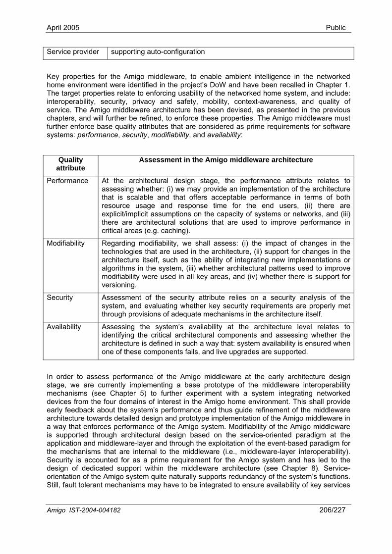
April 2005 Public
Service provider supporting auto-configuration
Key prhome eThe tarinterop security, privacy and safety, mobility, context-awareness, and quality of serchapte are must furtsystem
Quattri
operties for the Amigo middleware, to enable ambient intelligence in the networked nvironment were identified in the project’s DoW and have been recalled in Chapter 1. get properties relate to enforcing usability of the networked home system, and include: erability,
vice. The Amigo middleware architecture has been devised, as presented in the previous rs, and will further be refined, to enforce these properties. The Amigo middlew
her enforce base quality attributes that are considered as prime requirements for software s: performance, security, modifiability, and availability:
ality bute
Assessment in the Amigo middleware architecture
Perform l design stage, the performance attribute relates to ance At the architecturaassessing whether: (i) we may provide an implementation of the architecture that is scalable and that offers acceptable performance in terms of both resource usage and response time for the end users, (ii) there are explicit/implicit assumptions on the capacity of systems or networks, and (iii) there are architectural solutions that are used to improve performance in critical areas (e.g. caching).
Mod
architectural patterns used to improve
ifiability Regarding modifiability, we shall assess: (i) the impact of changes in the technologies that are used in the architecture, (ii) support for changes in the architecture itself, such as the ability of integrating new implementations or algorithms in the system, (iii) whether modifiability were used in all key areas, and (iv) whether there is support for versioning.
Security Assessment of the security attribute relies on a security analysis of the system, and evaluating whether key security requirements are properly met through provisions of adequate mechanisms in the architecture itself.
Availability Assessing the system’s availability at the architecture level relates to identifying the critical architectural components and assessing whether the architecture is defined in such a way that: system availability is ensured when one of these components fails, and live upgrades are supported.
In order to assess performance of the Amigo middleware at the early architecture design stage, we are currently implementing a base prototype of the middleware interoperability mechanisms (see Chapter 5) to further experiment with a system integrating networked
e four domains of interest in the Amigo home environment. This shall provide eararca way is suppapplica ugh the exploitation of the event-based paradigm for theSecuritdesignorienta ndancy of the system’s functions. Still, fault tolerant mechanisms may have to be integrated to ensure availability of key services
devices from thly feedback about the system’s performance and thus guide refinement of the middleware hitecture towards detailed design and prototype implementation of the Amigo middleware in
that enforces performance of the Amigo system. Modifiability of the Amigo middleware orted through architectural design based on the service-oriented paradigm at the
tion and middleware-layer and thro mechanisms that are internal to the middleware (i.e., middleware-layer interoperability).
y is accounted for as a prime requirement for the Amigo system and has led to the of dedicated support within the middleware architecture (see Chapter 8). Service-tion of the Amigo system quite naturally supports redu
Amigo IST-2004-004182 206/227
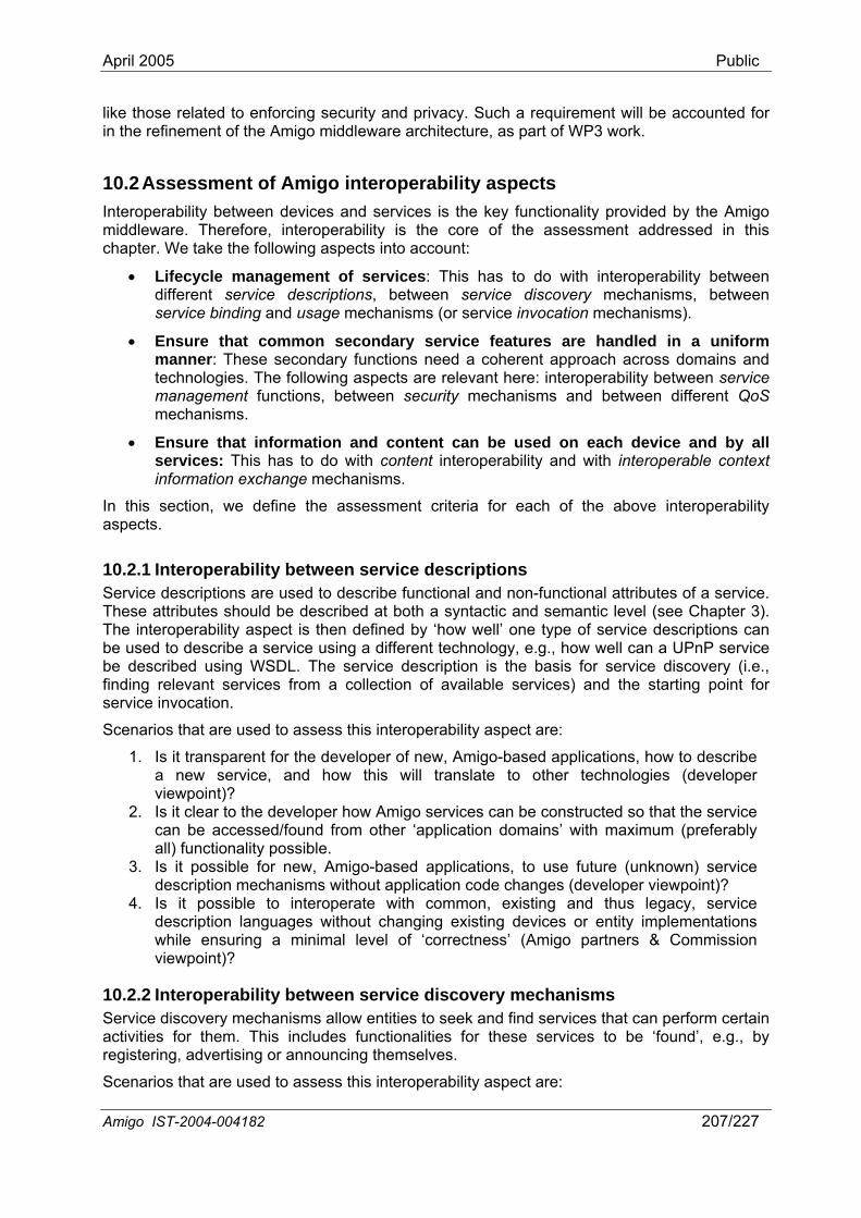
April 2005 Public
likein the r
10Interop functionality provided by the Amigo
iddleware. Therefore, interoperability is the core of the assessment addressed in this hapter. We take the following aspects into account:
agement of services: This has to do with interoperability between ms, between
• ures are handled in a uniform
In thisaspect
iptions and non-functional attributes of a service.
ucted so that the service can be accessed/found from other ‘application domains’ with maximum (preferably all) functionality possible.
3. Is it possible for new, Amigo-based applications, to use future (unknown) service description mechanisms without application code changes (developer viewpoint)?
4. Is it possible to interoperate with common, existing and thus legacy, service description languages without changing existing devices or entity implementations while ensuring a minimal level of ‘correctness’ (Amigo partners & Commission viewpoint)?
10.2.2 Interoperability between service discovery mechanisms Service discovery mechanisms allow entities to seek and find services that can perform certain activities for them. This includes functionalities for these services to be ‘found’, e.g., by registering, advertising or announcing themselves.
Scenarios that are used to assess this interoperability aspect are:
those related to enforcing security and privacy. Such a requirement will be accounted for efinement of the Amigo middleware architecture, as part of WP3 work.
.2 Assessment of Amigo interoperability aspects erability between devices and services is the key
mc
• Lifecycle mandifferent service descriptions, between service discovery mechanisservice binding and usage mechanisms (or service invocation mechanisms).
Ensure that common secondary service featmanner: These secondary functions need a coherent approach across domains and technologies. The following aspects are relevant here: interoperability between service management functions, between security mechanisms and between different QoS mechanisms.
• Ensure that information and content can be used on each device and by all services: This has to do with content interoperability and with interoperable context information exchange mechanisms.
section, we define the assessment criteria for each of the above interoperability s.
10.2.1 Interoperability between service descrService descriptions are used to describe functionalThese attributes should be described at both a syntactic and semantic level (see Chapter 3). The interoperability aspect is then defined by ‘how well’ one type of service descriptions can be used to describe a service using a different technology, e.g., how well can a UPnP service be described using WSDL. The service description is the basis for service discovery (i.e., finding relevant services from a collection of available services) and the starting point for service invocation.
Scenarios that are used to assess this interoperability aspect are:
1. Is it transparent for the developer of new, Amigo-based applications, how to describe a new service, and how this will translate to other technologies (developer viewpoint)?
2. Is it clear to the developer how Amigo services can be constr
Amigo IST-2004-004182 207/227
April 2005 Public
1. As above, is it transparent for the developer of new, Amigo-based applications, how to describe a new service, and how this will translate to other technologies (developer viewpoint)?
2. Is it possible for new, Amigo-based applications, to use future (unknown) service discovery mechanisms without application code changes (developer viewpoint)?
3. Is it possible to interoperate with common, existing and thus legacy, service discovery mechanisms without changing existing devices or entity implementations while ensuring a minimal level of ‘correctness’ (Amigo partners & Commission viewpoint)?
10.2.3 Interoperability between service binding mechanisms Service binding occurs after two (or more) entities have discovered each other. Binding makes it possible for these entities to actually start interacting (using/accessing), and includes setting up a network connection and, possibly, negotiating details on which protocol and/or protocol settings to use (e.g., big or little endian, whether to use compression, which port to use).
Scenarios that are used to assess this interoperability aspect are:
1. Is it transparent for the developer of new, Amigo-based applications, which binding mechanisms will actually be used during run-time (developer viewpoint)?
2. Is it possible for new, Amigo-based applications, to use future (unknown) binding mechanisms without application code changes (developer viewpoint)?
3. Is it possible to interoperate with common, existing and thus legacy, binding mechanisms without changing existing devices or entity implementations (Amigo partners & Commission viewpoint)?
10.2.4 Interoperability between service invocation mechanisms During service usage, two or more entities exchange messages according to some interaction protocol (i.e., connector-related behavior), transported over some already existing binding.
Scenarios that are used to assess this interoperability aspect are:
1. Is it transparent for the developer of new, Amigo-based applications, which service usage mechanisms will be used during run-time (developer viewpoint)?
2. Is it possible for the developer of new, Amigo-based applications, to use future (unknown) service usage mechanisms without application code changes (developer viewpoint)?
3. Is it possible to interoperate with common, existing and thus legacy, service usage mechanisms without changing existing devices or entity implementations (Amigo partners & Commission viewpoint)?
10.2.5 Interoperability between security mechanisms Security is a difficult problem for all architectures. It is a cross-cutting concern, in that all authentication and access control mechanisms that will be employed must somehow interoperate. Interoperability concerns are:
1. Some (legacy) devices may not have any security-provisions on-board. Are these devices able to use all services they would otherwise be able to use if Amigo-middleware was not in place?
2. Reverse from the previous one, are Amigo-based applications able to access services from these (legacy) devices?
3. Does the Amigo security mechanism compromise any of the existing security mechanisms for in-home communication from the consumer electronics or domotic domains?
Amigo IST-2004-004182 208/227
April 2005 Public
Amigo IST-2004-004182 209/227
4. Is the Amigo security mpublic services, e.g., to
echanism interoperable with security mechanisms used for allow for single sign-on at remote services, or to re-use
bility
incorporated for enhanced usage. Some pointers are further given to relevant language
‘outdoor’ credentials (e.g., SIM card) for in-door authentication?
5. Are security aspects like confidentiality, privacy, integrity, and DRM covered?
10.2.6 Interoperability between QoS mechanisms Support for Quality of Service (QoS) in the Amigo system basically amounts to allocation of resources for processing, storage and communication. Allocation of resources to users requires appropriate QoS mechanisms to enforce QoS agreements and to ensure that resources are allocated according to end-user requirements. Because QoS mechanisms require proper behavior of all potential users of system resources, it is important that all services and devices in the home properly use resource management functions. We use the following criteria in our assessment:
• Do the selected QoS mechanisms comply with existing or emerging standards (e.g., 802.11e for QoS management on wireless links, UPnP QoS)?
• To what extent are QoS guarantees possible when devices/services that share the same resources do not behave properly? This issue is important, because a lot of legacy devices (that are supported by Amigo) may not be QoS-aware.
10.2.7 Interoperability between context-exchange mechanisms There are no such standards in the consumer electronics and domotic world, and therefore interoperability is not really an issue right now.
10.2.8 Interoperability between service management mechanisms In this deliverable, service management is addressed from the standpoint of service discovery, and service binding and usage, for which assessment criteria have been introduced above. Other functions related to service management (e.g., accounting and billing) will be addressed in subsequent system design steps for which overall service management interoperability shall be dealt with.
10.3 Assessment results Assessment of the Amigo middleware architecture with respect to interoperability is based on the scenarios defined in the previous section, taking into account the state of the art surveyed in the companion Deliverable D2.2 [Amigo-D2.2]. The latter is mainly used to check whether relevant standards are taken into account with respect to the interoperability issues that are addressed in the Amigo middleware.
10.3.1 Assessment of service description interoperaChapter 3 details the current efforts towards Amigo service descriptions and discovery, which are to be complemented with application- and middleware-layer interoperability mechanisms (see Chapters 4&5) to ease interactions among the services that are networked within the home environment, ranging from Amigo-aware/enhanced services to legacy services.
Assessment: 1. This deliverable does not define the language for service descriptions, which is to be
specified as part of the middleware’s detailed design in Work package WP3. However, the deliverable gives an overview of the capabilities that service descriptions should have, i.e., semantic-level and context-related service descriptions should be
April 2005 Public
standards, e.g., OWL-S. Therefore, it is not (yet) possible to assess how convenient it is for developers to create new Amigo applications that can be found and selected,
be better exploited when the
cisions for
cular troduces the Amigo abstract service discovery architecture, and in Chapter 5, which
he design a specific interoperable service discovery component.
Assessment: 1. Chapter 3 mentions the usage of relevant Web Services standards for enhanced
service discovery, with respect to service description and matching. Which standards will be chosen and how these will be extended will be addressed during the architecture refinement in the next project phase. Then, convenience of enhanced Amigo service discovery from the perspective of the developers cannot be assessed at this stage. However, detailed design of the Amigo solution to interoperable service discovery, including possible performance enhancement using dedicated platform like OSGi, has already been addressed (see Chapter 5). The proposed architectural solution enables to integrate any legacy service discovery protocol as is.
2. The Amigo discovery architecture (see Chapter 3) specifies at a high level functionalities to enable Amigo-based applications to use future (unknown) service discovery mechanisms. It however depends on the refinement of this architecture whether this is actually possible. It especially depends on whether it is possible to semantically map the future service discovery mechanism to the Amigo mechanism (including whether the so-called mapping can be implemented).
3. Chapters 3 and 5 explicitly cover the most popular service discovery mechanisms, and state that the Amigo discovery architecture will interoperate with them.
although it is anticipated to be comparable to that of (semantic) Web services.
2. The description of networked services in the Amigo system may integrate semantic-level and/or context-related description or be a basic syntactic-only interface definition. Usage of all the functionalities of a new service willservice description embeds semantic and context information, and the service’s client integrates Amigo enhanced service discovery. Otherwise, a new service may be discovered and used by a non Amigo-aware client only if both the client and service developers use some standard interfaces for service descriptions, be they either syntactically equal interfaces or interfaces that are mapped to each other in the Amigo system.
3. The Amigo service discovery architecture identifies the need for interoperability to legacy and also future service discovery mechanisms and their corresponding service descriptions. This is encapsulated by the ‘Interoperable service discovery’ block in the architecture, which should however be elaborated in future refinements.
4. See point 2.
Recommendation: This deliverable does not define the language for ‘Amigo service descriptions’, which will be undertaken as part of the Amigo middleware’s detailed design during the next project phase. However, this deliverable has set base design deservice descriptions, with interoperability in mind. Future refinements should define the syntax and semantics for the Amigo service description language and should continue in the current spirit of interoperability. Relevant service description and service discovery technologies should be considered, as already taken into account in the elicitation of the middleware architecture. Furthermore, the architecture should anticipate future development like what is being done to incorporate contextual information in the service description.
10.3.2 Assessment of service discovery interoperability Service discovery in the Amigo middleware is addressed in Chapter 3, which in partiinintroduces t
Amigo IST-2004-004182 210/227
April 2005 Public
Recommendation: interoperability in min
The Amigo abstract service discovery architecture is designed with d as a major requirement, and thus covers it. Further refinement of the
lity shall allow for more thorough assessment, ti lar fro opers.
s g interoperability ad t of Chapter 5, which discusses service discovery and
teroperability. However, since hat subset of functionalities, which is offered by all
ered through this API. Consequences of this ings (or protocols and
iddle supported. This is a risk, but the impact of this largely implementation of this part of the architecture.
ve similar features as existing ones, ld be supported without requiring change to the
architecture, the generalized API must be detailed and and middleware technologies) that
sses interoperability otocol interoperability.
ent: ach for all different types of interaction dep bridging type of approach, on whether the
at are bridged have sufficiently comparable syntax, semantic expressiveness and hitecture is too abstract to be able to sufficiently assess
tural level defined in this deliverable, the proposed po nt scenarios.
ture, the proposed solution to interaction protocol ability ed with all combination of service usage sms ( ologies) that are relevant to Amigo. This will
id ntifying what is actually syntactically and semantically possible. Also, extendibility of shall be taken into consideration in the architecture
m nt.
.5 erability 8. The diversity of (legacy) devices and
abilitie explicitly mentioned. Therefore, the proposed inimal security requirements or protocols. Instead, an
ite ure ba s system idea is proposed, with Role Based Access Control exten building blocks are the Authentication
identity and service specific tokens that s.
can be applied to the service discovery process is further discussed in Chapter 3.
Amigo solution to service discovery interoperabiin par cu m the standpoint of devel
10.3.3 Asse sment of service bindinBinding is dressed as par
ss. usage/acce
Assessment: hapter 5 ensures in1. The generalized API discussed in C
this is a generalized API, only tservice binding mechanisms can be off
are for the service binddepend on what those differences m ware technologies)depends on the refinement and
2. Assuming new service binding mechanisms hafuture binding mechanisms shouapplication code.
3. See point 1. Recommendation: In the refinedmapped to all service binding mechanisms (thus protocols are relevant for Amigo.
10.3.4 A sment of service invocationChapter 5 addresses interaction pr Assessm The feasibility of the proposed approprotocols ends, as is the case with anyprotocols thprotocol messages. The current arcthis. However, at the abstract architecsolution sup rts all three assessme Recommendation: In the refined architecinteroper shall be detailed and experimentmechani thus protocols and middleware technallow ethe interoperability solution at run-time refine e
10.3 Assessment of security interopSecurity and privacy are mainly addressed in Chapterdifferent cap s with respect to security are security architecture does not impose march ct sed on the Kerbero(RBAC) ded to devices and services. The basicService and the Authorization Service, which provide are needed to access certain secured service
How the proposed security architecture
Amigo IST-2004-004182 211/227
April 2005 Public
Assessm ent:ot need authorization tokens to be provided by a ices without any security-provisions on-board are, s they would otherwise be able to use if Amigo
dle ce the Amigo middleware is not restrictive in this
he pr Amigo-based applications are not restricted (from a ecurit ssing services from these (legacy) devices.
mechanism compromises any of the existing security tioned in Chapter 8, since the chapter describes an
ity architecture ‘maps’ to existing security one can determine if existing security
mised. The link between the proposed abstract security mechanisms should become clear in the
ser can be used, divided into strong ow outside credentials to be (re-)used for in-door
uthen ith respect to Amigo system) services is also ked to an ‘external’ identity if the users’
entity ong mechanism.
curit rivacy, integrity, and DRM are covered. A DRM tanda in the abstract security architecture is proposed. The
addressed in
urity architecture operates at the application level Ami n of authentication and authorization services
should be e to diff not really clear from the presentation, although
ch lexible enough to suggest that this is possible. The refined sh nt; as is stated in Chapter 8: the level of scenario’s are d cture, for the definition of the concrete implementation,
Only after this is clear, the impact and ecurity mechanisms can be assessed.
es rability f QoS ive impact on the end-user experience of Amigo
ssesses interoperability between QoS mechanisms in
lude . allocation of buffers to compensate for jitter).
migo is currently not on a configurable middleware this
a trade-off between QoS ible to retransmit lost link-layer packets at the cost
e focus was on multimedia content transfer in rading factor).
1. Standard (unsecured) services do nclient. This means that (legacy) devin principle, able to use all servicemid ware was not in place, sinsense.
2. T evious also implies thats y point of view) from acce
3. Whether the Amigo security mechanisms is not explicitly menabstract security architecture. How the securmechanisms should be described first, before mechanisms are (possibly) comprosecurity architecture and existingrevised/detailed architecture.
4. Different mechanism to prove the idand weak ones. This would all
entity of a u
a tication. The link to external (wcan be linaddressed, where the user identity
id was first proven with a str
5. Se y aspects like confidentiality, ps rd for use in Amigo that fits security mechanisms used in different service discovery protocols are Chapter 3.
Recommendation: The abstract Amigo sec(including go middleware) and uses the notiofor providing identity and service tokens. How the proposed security architecturemapp d erent middleware technologies is the approa is generic and farchitecture ould take this into accousufficient for eriving an abstract architethe level of use-cases might be more appropriate.possible compromise of existing s
10.3.6 Ass sment of QoS interopeA lack o support will have a negatservices and applications. This section athe Amigo infrastructure. QoS concerns are mainly addressed in Chapter 6.
Assessment: The focus in Chapter 6 is on link-layer QoS mechanisms and seems to exc
application-level QoS support (e.gHowever, as the focus of Aseems for now the right direction.
The QoS requirements are not clear. Usually there is dimensions. For example, is it possof a lower goodput (i.e., currently, thwhich retransmitting packets are a deg
Amigo IST-2004-004182 212/227
April 2005 Public
The QoS control solutions that are discussed, aim for a ‘per flow’ reservation of ecommended UPnP QoS, seems to lean towards ‘class-s (like DiffServ). It is not clear how these solutions relate.
achieved by using standards defined by the t Amigo follows the emerging UPnP QoS standard
entation plans
eems a promising way forward.
refined architecture, between per-flow-based resource d resource reservation.
s-layer QoS concerns and possible feature echanisms at the platform, middleware and application
rs. w would a per-flow reservation mechanism at the middleware r be per-traffic-class reservation mechanism at the platform layer?
mechanisms outside the home environment on the public Internet)?
, QoS dimensions (such as speed, goodput and t are needed to support the Amigo scenarios and
lu commendations n discusse the Amigo abstract architecture. We found
hod to execute the assessment. As the main focus of the ig as interoperability, we also focused on this aspect in the
. We first identified stakeholders and then defined relevant assessment scenarios scenarios were then assessed against the proposed
and recommendations are divided in the several key eas of the a discovery mechanisms, QoS mechanisms, etc.
as inputs for the refined architecture.
sm that there are no major obstacles, although several dati ount during the follow-up activities on Amigo
t, in Work Package WP3.
resources (like IntServ). The rbased’ reservation of resource
QoS interoperability is expected to be DLNA forum. It is recommended thaaligns with the DLNA QoS implem
Recommendations: Continue on the UPnP QoS path, as it s
Make a choice, in the reservation and class-base
Identify, in the refined architecture, the crosinteractions between QoS mlaye For example, holaye supported by a
Also, consider interoperability with QoS (e.g., a video is delivered from a server
Define, in the refined architecturedelay) and QoS requirements thaguarantee a high-quality end-user experience.
10.4 Conc sions and reThis sectio d the assessment of inspiration in the IEEE ATAM metabstract Am o architecture wassessmentfor these stakeholders. The definedAmigo abstract architecture. Our findingsresearch ar rchitecture, like service The proposed recommendations can be used
The asses ent indicated recommen ons must be taken into accmiddleware developmen
Amigo IST-2004-004182 213/227

April 2005 Public
11 Conclusion Th pintelligence vis networked home system towards that ob s tapplication domEnabling such erability among the networked devices and ho iceabstract archite
The Amigo syoffering a networked home system structured around autonomous, loosely coupled services th le toen nt. Iapplication- an o sy itebetween / comThe conforman nd middleware layers of the Amigo sy itere ndproperties. Theprovided service operations in terms of middleware-layer service discovery and interaction pr dinteroperabilityreasoning about service properties at a semantic level. This further promotes openness of the Am e sthe iorconformance reconformance that is then enabled depends on the cinteroperability method ming parts. This deliverable has in ebe further deveinteroperabilityregarding in particular performance issue, is key to the acceptance of the Amigo system, de ignpro ple
Any device thaUPnP service) y method may be integrated within the Am .if either at le sis a gateway further introduces Amigo-enhancedfor increase interopera
Se taintegration of PC- andarchitecture. Hrequirements, extensively add Integration of C ntroduce the Amigo multimedia streaming architecture that is based otar ropearchitecture sparchitecture with functionalities for the streaming and storage of multimedia content.
e Amigo roject aims to develop a networked home system enabling the ambient ion. Key feature targeted for the Amigo
jective, i o effectively integrate and compose devices and services from the four ains that are met in today’s home, i.e., CE, domotic, mobile and PC domains.
a feature requires supporting interopsted serv s, which defines the core requirement for the Amigo middleware, whose
cture design has been introduced in this deliverable.
stem architecture is based on the service-oriented architectural style, hence
at are abvironme
communicate, compose and evolve in an open, dynamic and heterogeneous nteroperability among heterogeneous services is further supported through d middleware-layer interoperability methods that are key elements of the Amig
stem arch cture. Specifically, the Amigo interoperability methods enable interaction position of heterogeneous services, according to given conformance relations. ce relations apply to both the application a
stem archquested a
cture. The former relates to reasoning about the compatibility between provided service operations in terms of functional and non-functional latter relates to reasoning about the compatibility between requested and
otocols, an enforced quality. The proposed conformance relations and related methods exploit ontology-based modeling of services, enabling rigorous
igo homir behav
ystems, by enabling interoperability among networked services according to al specification, as opposed to their rigid syntactic interfaces. Various lations may be considered for the Amigo networked home systems. The partial
apacity to deploy an adequate to compensate for the non-confor
troduced sp cific application-layer and middleware-layer interoperability methods, which will loped in the next project phase, while still allowing the definition of alternative
methods. Since supporting effective middleware-layer interoperability,
tailed destotype im
of related methods have been presented in this deliverable. In addition, mentation is already under way.
t implements any technology-specific client and/or service (e.g., Web service, and possibly some Amigo interoperabilit
igo systema
Then, two devices that host heterogeneous service infrastructures may interact t one of them embeds Amigo middleware-layer interoperability methods or there embedding the necessary interoperability methods. The Amigo middleware
services, enriched with semantic and context information, d
rvice-orien
bility but also context-aware usage.
tion has already been successfully used in the mobile and PC domains. Hence, mobile-related devices is rather directly supported by the Amigo system
owever, the CE and domotic system architectures have specific features and which makes related integration less obvious. This issue has been quite ressed in this deliverable, in the light of relevant technological developments. E devices leads us to in the DLNA (Digital Living Network Alliance) interoperability guidelines, which rability in streaming media systems. The Amigo multimedia streaming ecifically enriches the base Amigo service-oriented interoperable system
get inte
Amigo IST-2004-004182 215/227
April 2005 Public
In of components, to
Independent o t are integrated within Amigo, one ke his security and ve been introduced based on th f
The middlewarundertaken ba tified for the Amigo middleware in the course of the pr iopr mThese requiremmiddleware arc d design and prototype implementation, it wa o middleware-rel ts elicited in W ag aaddressed in tarchitecture m the Amigo networked home sy idguidelines havdetailed design .
Th intethe Amigo networked home system. The Amigo system needs to integrate intelligent user se enrel icewill be presen all Amigo system architecture will then be re chprototype implethrough the dev d safety, home information and en t, ackages WP5-7.
tegration devices from the domotic domain leads us to introduce discoverable proxy be associated with devices.
f the specifics of the application domains thay property t at must be guaranteed to the end-users by the Amigo networked home system
privacy. Middleware-related security services hae specifics o security and privacy in the home environment.
e architectural design that has been presented in this document has been sed on requirements iden
oject definitevious syste
n, which followed from assessment and lessons learnt from the development of s aimed at enabling ambient intelligence (see Deliverable D2.2 [Amigo-D2.2]). ents are introduced in the Amigo DoW. However, prior to refine the Amigo
hitecture towards the system’s detailes crucial t thoroughly validate our design choices, and, in particular, assess them against
ated technical requirements deriving from the user requiremenork packageainst the v
WP1. In a similar way, it was crucial to assess the Amigo middleware solution rious interoperability aspects of relevance. Both assessments have been his deliverable, from which we may conclude that the proposed middleware eets the middleware-related requirements for
stem, cons ering the abstract level of the architecture design. In addition, a number of e to be accounted for in the middleware architecture refinement towards and prototype implementation, in Work package WP3
e Amigo roperable middleware addresses part of the usability requirement, identified for
rvices for ated serv
hanced usability and high attractiveness to end-users. Architectural design of s is being started and will complement the Amigo middleware architecture, as ted in Deliverable D2.3. The over
fined in te nical Work packages WP3 and WP4, which will deliver detailed design and mentation. The Amigo system will then be experimented with and assessed elopment of applications from the home care an
tertainmen and extended home environment domains, within Work p
Amigo IST-2004-004182 216/227
April 2005 Public
Acronyms AAC
ACL
AS
AV
BCI
BD
CAD
CAM
CB
CD
CE
CEA
CENELEC ittee
Co
CP Point
CR
CSMA
DD
DHCP
DLNA Digital Livin
DMP
DMR
DM
DR
DSCP
DVD
EH
EHSA
EI
EIBA
EPF Electronic Picture Frame
FC Feature con
GENA
G
GUI
Advanced Audio Coding
Access Control List
Authorization Scheme
Audio/Video
BatiBUS Club International
F Bus Domotico Fagor (Fagor Domotic Bus)
Computer Aided Design
Computer Aided Manufacturing
R Constant Bit Rate
Collision Detection
Consumer Electronics
Consumer Electronics Association
European Electronics Standard Comm
D Complex Device
Control
C Cyclic Redundancy Check
Carrier Sense Multiple Access
Device Descriptor
Dynamic Host Configuration Protocol
g Network Alliance
Digital Media Player
Digital Media Renderer
S Digital Media Server
M Digital Rights Management
Differentiated Services Code Point
Digital Versatile Disc
S European Home System
European Home Systems Association
B European Installation Bus
European Installation Bus Association
troller
Generic Event Notification Architecture
IF Graphics Interchange Format
Graphical User Interface
Amigo IST-2004-004182 217/227
April 2005 Public
HA
HTML HT
IETF IN
IO
IP
IR
IS
IT
JC
JPEG
LO
LPCM
MAC Medium Acc
MAC MPDU
M
NPDU
O
OSI
P2P Peer-to-Peer
PC
PD
PH
PK
PNG Portable Network Graphics
PV
QM
Q
RBAC rol
RR
RSVP
RTCP
RTP
RT
SAML
Vi Home Audio Video interoperability
Hypertext Markup Language
TP Hypertext Transfer Protocol
Internet Engineering Task
Intermediate Node
G Inter-Operability Group
Internet Protocol
Information Retrieval
O International Standards Organization
Information Technology
P Java Community Process
Joint Photographic Experts Group
N Local Operation Network
Linear Pulse Code Modulation
ess Control
Message Authentication Code
MAC Protocol Data Units
PEG Moving Pictures Experts Group
Network Protocol Data Unit
SGi Open Service Gateway Initiative
Open Standard Interconnection
Personal Computer
U Protocol Data Unit
Policy Holder
I Public Key Infrastructure
R Personal Video recorder
QoS Manager
oS Quality of Service
Role Based Access Cont
Receiver Report
Resource Reservation Protocol
Real-Time Control Protocol
Real-Time Transport Protocol
SP Real-Time Streaming Protocol
Security Assertion Mark-up Language
Amigo IST-2004-004182 218/227
April 2005 Public
SCC
SD
SDI
SD
SHA SLA
SL
SOAP
SR
SS
SSL
SSO STB
TC
TDM
TIFF Tagged Image File For
TLS TV
UD
UI
UP
UP
VCR Videocasset
W3C
WS
XM
Standard Control Committee
Service Discovery
Service Discovery Infrastructure
P Service Discovery Protocol
Secure Hash Algorithm
Service Level Agreement
P Service Location Protocol
Simple Object Access Protocol
Sender Report
DP Simple Service Discovery Protocol
Secure Socket Layer
Single Sign-On
Set Top Box
P Transmission Control Protocol
Time Division Multiplexing
mat
Transport Layer
Television
P User Datagram Protocol
User Interface
User Priority
nP Universal Plug & Play
te recorder
World Wide Web Consortium
Web Service
L eXtensible Markup Language
Amigo IST-2004-004182 219/227

April 2005 Public
References [AaHo04] W.M.P. van der Aalst and A.H.M. ter Hofstede. Yawl: Yet another workflow
language. Information Systems, 2004.
[AlDi97] Bob Allen, Brian Dillon, Environmental Control and Field Bus systems, 1997, www.stakes.fi/cost219/fieldbus.doc
[AlGa97] R. Allen and D. Garlan. A Formal Basis for Architectural Connection. ACM Transactions on Software Engineering and Methodology, 6(3):213-249, 1997.
[Amigo-D1.2]
Amigo Consortium. Deliverable D1.2: Report on user requirements. February 2005.
[Amigo-D2.2]
Amigo Consortium. Deliverable D2.2: State of the art analysis including assessment of system architectures for ambient intelligence. February 2005.
[AnHS02] Anupriya Ankolekar, Frank Huch and Katia Sycara. Concurrent Execution Semantics for DAML-S with Subtypes. In Proceedings of The First International Semantic Web Conference (ISWC), 2002.
[AuCH98] C. Aurrecoechea, A. Campbell, and L. Hauw. A survey of QoS architectures. ACM/Springer Verlag Multimedia Systems Journal, Special Issue on QoS Architectures, 1998.
[AVMM04] Rohit Aggarwal, Kunal Verma, John Miller and Willie Milnor. Dynamic web service composition in meteor-s. Technical report, LSDIS Lab, Computer Science Dept., UGA, 2004.
[BaVi03] Sharad Bansal and Jose M. Vidal. Matchmaking of web services based on the DAML-S service model. In Proceedings of the second international joint conference on Autonomous agents and multi-agent systems, pages 926–927. ACM Press, 2003.
[BCPV04] Antonio Brogi, Carlos Canal, Ernesto Pimentel and Antonio Vallecillo. Formalizing web services choreographies. In Proceedings of the First International Workshop on Web Services and Formal Methods, Pisa, Italy, February 2004.
[BeGI05] Sonia Ben Mokhtar, Nikolaos Georgantas and Valérie Issarny. Ad Hoc Composition of User Tasks in Pervasive Computing Environments. In Proceedings of the International Workshop on Software Composition (SC 2005), Edinburgh, Scotland, April 2005.
[BeRe00] C. Bettstetter and C. Renner. A Comparison of Service Discovery Protocols and Implementation of the Service Location Protocol. In Proceedings of the 6th EUNICE Open European Summer School: Innovative Internet Applications, 2000.
[BLHL01] Tim Berners-Lee, James Hendler, Ora Lassila. The Semantic Web. Scientific American, May 2001
[BLSI03] Malika Boulkenafed, Jinshan Liu, Daniele Sacchetti, Valérie Issarny. Group Management in Mobile Ad Hoc Networks: Design, Implementation and Experiments. INRIA Research Report 5060, December 2003, INRIA-Rocquencourt, France.
[BrIs04] Yerom-David Bromberg, Valerie Issarny. Service Discovery Protocols Interoperability in the Mobile Environment. In Proceedings of the International Workshop Software Engineering and Middleware (SEM). September 2004.
Amigo IST-2004-004182 221/227
April 2005 Public
Amigo IST-2004-004182 222/227
[Broe04] T. Broens. Context-aware, Ontology-based, Semantic Service Discovery. Thesis for a Master of Science degree in Telematics from the University of Twente, Enschede, The Netherlands, 2004.
[BYRR99] R.Baeza-Yates, B.Ribiero-Neto and B.Ribeiro-Neto. Modern Information Retrieval. Pearson Education, 1st edition, 1999.
[CBCP02] G. Coulson, G. Blair, M. Clarke and N. Parlavantzas. The design of a configurable and reconfigurable middleware platform. In Distributed Computing. April 2002.
[CBM+02] L. Capra, G. Blair, C. Mascolo, W. Emmerich, P. Grace. Exploiting reflection in mobile computing middleware. In ACM Mobile Computing and Communications Review, May 2002.
[ClKK02] Clements, P.; Kazman, R.; & Klein, M. Evaluating Software Architectures: Methods and Case Studies. Boston, MA: Addison-Wesley, 2002.
[CuMW01] Curbera, F., Mukhi, N., Weerawarana, S. On the Emergence of a Web Services Component Model. In Proceedings of the WCOP 2001 workshop at ECOOP 2001, Budapest, Hungary, June 2001.
[DeSA01] Dey, A. K.; Salber, D.; Abowd, G. D., 2001. A conceptual framework and a toolkit for supporting the rapid prototyping of context-aware applications. Human-Computer Interaction, 16, pp. 97-166, 2001.
[DiAl99] T. Dierks, C. Allen, The TLS Protocol Version 1.0, Internet RFC-2246, January 1999.
[DiKS00] D. Dietrich, W. Kastner, T. Sauter, EIB Gebäudebussystem, ISBN: 3778527959 Hüthig Verlag, 2000
[DiLS00] H. Dijk, K. Langendoen, and H. Sips. ARC: A bottom-up approach to negotiated QoS. In Proceedings of the IEEE Workshop on Mobile Computing Systems and Applications (WMCSA'00), 2000.
[DLN04a] DLNA, Overview and Vision (White Paper), June 2004.
[DLN04b] DLNA, Home Networked Device Interoperability Guidelines v1.0, 2004.
[Fiel99] R. Fielding et al., Hypertext Transfer Protocol – HTTP/1.1, Internet RFC-2616, June 1999.
[Fout01] T. Fout. Universal Plug and Play in Windows XP (White Paper), 2001.
[FrHi98] Friedman-Hill, E. Jess, The Java Expert System Shell. SAND98-8206, Version 4.0, Distributed Computing Systems, Sandia National Laboratories, Livermore, CA, 1998.
[FSAK01] X. Fu, W. Shi, A. Akkerman, and V. Karamcheti. CANS: composable, adaptive network services infrastructure. In Proceedings of the USENIX Symposium on Internet Technologies and Systems (USITS), 2001.
[FUMK03] Howard Foster, Sebastian Uchitel, Jeff Magee and Jeff Kramer. Model-based verification of web service compositions. In IEEE International Conference on Automated Software Engineering, 2003.
[Garl03] D. Garlan. Formal modeling and analysis of software architecture: Components, connectors, and events. In Third International School on Formal Methods for the Design of Computer, Communication and Software Systems. September 2003.
[GBS03a] P. Grace, G. Blair and S. Samuel. Middleware awareness in mobile computing. In Proceedings of the 1st international ICDCS Workshop on Mobile Computing
April 2005 Public
Amigo IST-2004-004182 223/227
Middleware, May 2003.
[GBS03b] P. Grace, G. Blair and S. Samuel. A marriage of Web services and reflective middleware to solve the problem of mobile client interoperability. In Proceedings of Workshop on Middleware Interoperability of Enterprise Applications, September 2003.
[GBTI05] N. Georgantas, S. Ben Mokhtar, F. Tartanoglu, V. Issarny. Semantics-Aware Services for the Mobile Computing Environment. In A. Romanovsky, C. Gacek, R. de Lemos (Eds.), Architecting Dependable Systems III, Lecture Notes in Computer Science, Springer-Verlag, 2005 (to appear).
[GCTB01] Gonzalez-Castillo Javier, Trastour David and Bartolini Claudio. Description logics for matchmaking of services. In Proceedings of the KI-2001, Workshop on Applications of Description Logics, Vienna, Austria, September 2001.
[GPVD99] E. Guttman, C. Perkins, J. Veizades, M. Day. Service Location Protocol, Version 2. IETF RFC 2608, June 1999.
[HaBe03] Hamadi Rachid and Benatallah Boualem. A petri net-based model for web service composition. In Klaus-Dieter Schewe and Xiaofang Zhou, editors, Fourteenth Australasian Database Conference (ADC2003), volume 17 of Conferences in Research and Practice in Information Technology, pages 191–200, Adelaide, Australia, 2003, ACS.
[Hand98] M. Handley et al, SDP: Session Description Protocol, Internet RFC-2327, April 1998.
[HIM+04] Hitachi Ltd., Intel corp., Matsushita Ltd., Sony corp., Toshiba corp., Digital Transmission Content Protection Specification, Version 1.3, http://www.dtcp.com/data/info_20040107_dtcp_Vol_1_1p3.pdf, January 2004.
[HoMU00] John E. Hopcroft, Rajeev Motwani and Jeffrey D. Ullman. Introduction to Automata Theory, Languages, and Computation (2nd Edition). Addison-Wesley, 2000.
[HPFS02] R. Housley, W. Polk, W. Ford, D. Solo, Internet X.509 Public Key Infrastructure Certificate and Certificate Revocation List (CRL) Profile, Internet RFC-3280, April 2002.
[InUP03] Intel, Overview of UPnP Architecture, February 2003.
[IST+04] Valerie Issarny, Daniele Sacchetti, Ferda Tartanoglu, Francoise Sailhan, Rafik Chibout, Nicole Levy, Angel Talamona. Developing Ambient Intelligence Systems: A Solution based on Web Services. In Journal of Automated Software Engineering, Vol. 12(1), January 2005.
[IsTa05] Valérie Issarny, Ferda Tartanoglu. Specifying Web services recovery support with conversations. In Proceedings of the 38th Hawaii International Conference on System Sciences (HICSS-38), January 2005.
[ITLS04] V. Issarny, F. Tartanoglu, J. Liu, F. Sailhan. Software Architecture for Mobile Distributed Computing. In Proceedings of 4th Working IEEE/IFIP Conference on Software Architecture (WICSA’04). 12-15 June 2004. Oslo, Norway.
[Jarn04] Dmitri Jarnikov, Private communication on transcoding, 2004.
[KaBa02] Rick Kazman, Len Bass, Making Architecture Reviews Work in the Real World, IEEE Software, January/February 2002, pp 67-73.
[KJMS00] A.Kung, B.Jean-Bart, O.Marbach, S.Sauvage, The EHS European Home System Network, Trialog, Ref. TR/00/019/DT, Paris, 2000
April 2005 Public
Amigo IST-2004-004182 224/227
[KlB04a] M. Klein and A. Berndtein. Towards High-Precision Service Retrieval. IEEE Internet Computing, Jan-Feb, 2004
[KlB04b] Klein M., Bernstein A. Towards high-precision service retrieval. In Ian Horrocks and James Hendler, editors, Proceedings of The First International Semantic Web Conference (ISWC), 2002, number 2342 in Lecture Notes in Computer Science. Springer-Verlag, 2342, 2002.
[KoBr03] M. Koshkina and F. van Breugel. Verification of business processes for web services. Technical report, York University, 2003.
[KoNe93] J. Kohl and B. Neuman, The Kerberos Authentication Service (V5), Internet RFC-1510, September 1993.
[KoRe03] J. Kopena and W. C. Regli. DAMLJessKB: A Tool for Reasoning with the Semantic Web. In ISWC 2003, 2003.
[LeMS02] L. Lenzini, E. Mingozzi, G. Stea, A unifying service discipline for providing rate-based and fair queuing services based on Time Token protocol, IEEE Transactions on Computers, Vol. 51, Sept 2002, pp 1011-1025.
[LiIs04] Jinshan Liu, Valerie Issarny. QoS-aware Service Location in Mobile Ad Hoc Networks. In Proceedings of the 5th IEEE International Conference on Mobile Data Management (MDM'2004), January 2004.
[MaCE02] C. Mascolo, L. Capra, W. Emmerich. Middleware for mobile computing (A survey). In Advanced Lectures in Networking. Editors E. Gregori, G. Anastasi, S. Basagni. Springer. LNCS 2497. 2002.
[MaKr96] J. Magee and J. Kramer. Dynamic Structure in Software Architecture. In Proceedings of the ACM SIGSOFT'96 Symposium on Foundations of Software Engineering, pages 3-14, 1996.
[MaWG04] Shalil Majithia, David W. Walker and W. A. Gray. A framework for automated service composition in service-oriented architecture. In 1st European Semantic Web Symposium, 2004.
[McBr01] B. McBride. Jena: Implementing the RDF Model and Syntax Specification. In Semantic Web Workshop, WWW 2001, 2001.
[McMa03] S. McIlraith, D. Martin. Bringing Semantics to Web Services, IEEE Intell. Syst., 18 (1) (2003), 90–93.
[MeBE03] B. Medjahed, A. Bouguettaya, and A. Elmagarmid. Composing Web Services on the Semantic Web. The VLDB Journal, 12(4):333-351, November 2003.
[MeMP99] N. Mehta, N. Medvidovic, and S. Phadke. Towards a taxonomy of software connectors. In 21st International Conference on Software Engineering, November 1999.
[Miln99] R. Milner. Communicating and Mobile Systems: The π-Calculus. Cambridge University Press, 1999.
[MPM+04] D. Martin, M. Paolucci, S. McIlraith, M. Burstein, D. McDermott, D. McGuinness, B. Parsia, T. Payne, M. Sabou, M. Solanki, N. Srinivasan, K. Sycara. Bringing Semantics to Web Services: The OWL-S Approach. In Proceedings of the First International Workshop on Semantic Web Services and Web Process Composition (SWSWPC 2004), July 6-9, 2004, San Diego, California, USA.
[NaMc02] Srini Narayanan and Sheila A. McIlraith. Simulation, verification and automated composition of web services. In Proceedings of the eleventh international
April 2005 Public
Amigo IST-2004-004182 225/227
conference on World Wide Web, pages 77–88, ACM Press, 2002.
[NKHM04] A. Nadalin, C. Kaler, P. Hallam-Baker, R. Monzillo, Web Service Security, http://docs.oasis-open.org/wss/2004/01/oasis-200401-wss-soap-message-security-1.0.pdf, March 2004.
[NoMc01] Natalya F. Noy and Deborah L. McGuinness. Ontology Development 101: A Guide to Creating Your First Ontology. Stanford Knowledge Systems Laboratory Technical Report KSL-01-05 and Stanford Medical Informatics Technical Report SMI-2001-0880, March 2001.
[OSLe03] Declan O'Sullivan and David Lewis. Semantically Driven Service Interoperability for Pervasive Computing. In Proceedings of the Third ACM International Workshop on Data Engineering for Wireless and Mobile Access, MobiDE 2003, September 19, 2003, San Diego, California, USA.
[OSS+03] Otero Perez, C. M.; Steffens, L.; van der Stok, P.; van Loo, S.; Alonso, A.; Ruiz, J. F.; Bril, R. J.; Valls, M. G. QoS-based resource management for ambient intelligence. Source: Ambient intelligence: impact on embedded system design, pp. 159--182, 1-4020-7668-1, Kluwer Academic Publishers, Norwell, MA, USA, 2003.
[PaGe03] M. P. Papazoglou, D. Georgakopoulos (Eds.). Service-oriented computing. Special section in Communications of the ACM, Volume 46, Issue 10, October 2003.
[PaPi95] T. Parker and D. Pinkas, SESAME Technology Version 4 Overview, https://www.cosic.esat.kuleuven.ac.be/sesame/doc-txt/overview.txt, December 1995.
[PASS03] Massimo Paolucci, Anupriya Ankolekar, Naveen Srinivasan and Katia Sycara. The DAML-S Virtual Machine. In Proceedings of the Second International Semantic Web Conference (ISWC), 2003, Sandial Island, Fl, USA, October 2003, pp. 290-305.
[PaSy03] M. Paolucci and K. Sycara, Autonomous Semantic Web Services, IEEE Internet Computing, vol. 7, no. 5, September/October 2003.
[PFSi03] J. G. Pereira Filho and M. van Sinderen. Web service architectures - semantics and context-awareness issues in web services platforms. Technical report, Telematica Instituut, 2003.
[PiTB03] T.Piloura, A.Tsalgatidou, and A.Batsakis. Using WSDL/UDDI and DAML-S in Web Service Discovery. In the Proceedings of Workshop on E-services and Semantic Web (ESSW), Budapest, Hungary, May 2003.
[PKPS02] Massimo Paolucci, Takahiro Kawamura, Terry R. Payne, and Katia Sycara. Semantic Matching of Web Services Capabilities. In Proceedings of the 1st International Semantic Web Conference (ISWC 02), 2002.
[RCG+03] Rios, D.; Costa, P.D.; Guizzardi, G.; Ferreira Pires, L.; Pereira Filho, J.G., van Sinderen, M. Using ontologies for modeling context-aware service platforms. In OOPSLA 2003 Workshop on Ontologies to Complement Software Architectures, Anaheim, CA, USA, 2003.
[Rit02a] J. Ritchie et al., UPnP AV Architecture: 0.83, June 2002.
[Rit02b] J. Ritchie, MediaServer:1 Device Template Version 1.01, June 2002
[Rit02c] J. Ritchie, MediaRenderer:1 Device Template Version 1.01, June 2002
[RoPM00] G.-C. Roman, G. Picco, and A. Murphy. Software Engineering for Mobility: A Roadmap. In Proceedings of the 22nd International Conference on Software
April 2005 Public
Amigo IST-2004-004182 226/227
Engineering (ICSE’22), 2000.
[Rose02] J. Rosenberg et al, SIP: Session Initiation Protocol, Internet RFC-3261, June 2002.
[RyWo04] N. Ryan and A. Wolf. Using event-based parsing to support dynamic protocol evolution. In Proceedings of the 26th International Conference on Software Engineering (ICSE'04), 2004
[ScAW94] Schilit, B.; Adams, N.; Want, R., 1994. Context-Aware Computing Applications. IEEE Workshop on Mobile Computing Systems and Applications, Santa Cruz, California, USA, 1994.
[SCD+97] B. Sabata, S. Chatterjee, M. Davis, J. Sydir, and T. Lawrence. Taxonomy for QoS specification. In Proceedings of the International Workshop on Object-oriented Real-time Dependable Systems (WORDS'97), 1997.
[Schu03] Schulzrinne et al., RTP: A Transport Protocol for Real-Time Applications, Internet RFC-3550, July 2003.
[Schu98] Schulzrinne et al., Real Time Streaming Protocol (RTSP), Internet RFC-2326, April 1998.
[SPAS03] Katia Sycara, Massimo Paolucci, Anupriya Ankolekar and Naveen Srinivasan. Automated discovery, interaction and composition of semantic Web services. Journal of Web Semantics: Science, Services and Agents on the World Wide Web, 1(1):27–46, December 2003.
[StCA94] P.D.V. van der Stok, M.M.M.P.J. Claessen and D. Alstein, A hierarchical membership protocol for synchronous distributed systems, 1st European Dependable Computing Conference, 4-6 Oct, Berlin, LNCS 852, Springer-Verlag, pp 597-616, 1994.
[SunJ99] Sun. Technical White Paper: Jini Architectural Overview. 1999.
[Tane03] A.S. Tanenbaum, Computer Networks, 4th edition, Pearson Education International, 2003.
[TBGC01] David Trastour, Claudio Bartolini and Javier Gonzalez-Castillo. A semantic web approach to service description for matchmaking of services. In First Semantic Web Working Symposium, Stanford University, California, USA, July 30 - August 1, 2001SWWS, pages 447–461, 2001.
[TsAH04] A. Tsounis, C. Anagnostopoulos, and S. Hadjiefthymiades. The Role of Semantic Web and Ontologies in Pervasive Computing Environments. In Proceedings of Mobile and Ubiquitous Information Access Workshop, Mobile HCI '04, Glasgow, UK, Sept. 2004.
[UPnP00] Universal Plug and Play Forum. Universal Plug And Play Device Architecture. 2000.
[Veri94] P. Verissimo, Real-time communication in distributed systems, ed. S. Mullender, Addison Wesley, 2nd ed., 1994.
[Wald99] Waldo, J. (1999). The Jini Architecture for Network-centric Computing. In Communications of the ACM, July 1999, pp. 76-82.
[WSS+01] A. Westerinen, J. Schnizlein, J. Strassner, M. Scherling, B. Quinn, S. Herzog, A. Huynh, M. Carlson, J. Perry, S. Waldbusser. Terminology for Policy-Based Management. IETF RFC 3198, 2001.
[ZhCL04] C.Zhou, L.-T.Chia, and B.-S.Lee. DAML-QoS Ontology for Web Services. ICWS-04, July 6-9, San Diego, California, USA.

April 2005 Public
Amigo IST-2004-004182 227/227
Related Documents