Specification and Validation of Control-Intensive Integrated Circuits in hopCP VENKATESH AKELLA GANESH GOPALAKRISHNAN UUCS-92-001 Department of Computer Science University of Utah Salt Lake City, UT 84112, USA January 22, 1992 Abstract Control intensive ICs pose a significant challenge to the users of formal methods in designing hardware. These ICs have to support a wide variety of requirements including synchronous and asynchronous opera- tions, polling and interrupt-driven modes of operation, multiple concurrent threads of execution, complex computations, and programmability In this paper, we illustrate the use of formal methods in the design of a control intensive IC called the “Intel 8251” Universal Synchronous/Asynchronous Receiver/Transmitter (USART), using our formal hardware description language ‘hopCP’. A feature of hopCP is that it supports communication via asynchronous ports (distributed shared variables writable by exactly one process), in addition to synchronous message passing. We show the usefulness of this combination of communication constructs. We outline static analysis algorithms to determine safe usages of asynchronous ports, and also to discover other static properties of the specification. We discuss a compiled-code concurrent functional simulator called CFSIM, as well as the use of concurrent testers for driving CFSIM. The use of a seman- tically well specified and simple language, and the associated analysis/simulation tools helps conquer the complexity of specifying and validating control intensive ICs.

Welcome message from author
This document is posted to help you gain knowledge. Please leave a comment to let me know what you think about it! Share it to your friends and learn new things together.
Transcript
Specification and Validation of Control-Intensive Integrated Circuits in hopCP
V EN K A TESH AKELLA G ANESH G O PA LA KRISH NA N
UUCS-92-001
D epartm en t of C om puter Science U niversity of U tah
Salt Lake City, U T 84112, USA
January 22, 1992
A b strac t
Control intensive ICs pose a significant challenge to the users o f form al m ethods in designing hardware. These ICs have to support a wide variety o f requirements including synchronous and asynchronous operations, polling and interrupt-driven m odes o f operation, m ultiple concurrent threads o f execution, com plex com putations, and program m ability In this paper, we illustrate the use o f form al m ethods in the design o f a control intensive IC called the “Intel 8251” Universal Synchronous/Asynchronous R eceiver/T ransm itter (U SART), using our form al hardware description language ‘h opC P ’. A feature o f hopC P is that it supports communication via asynchronous po rts (d istribu ted shared variables writable by exactly one process), in addition to synchronous message passing. We show the usefulness o f this com bination o f communication constructs. We outline s ta tic analysis algorithm s to determ ine safe usages o f asynchronous ports, and also to discover other sta tic properties o f the specification. We discuss a com piled-code concurrent functional sim ulator called C F S IM , as well as the use o f concurrent testers for driving CFSIM. The use o f a sem antically well specified and sim ple language, and the associated analysis/sim ulation tools helps conquer the com plexity o f specifying and validating control intensive ICs.
Forma] Aspects of VLSI Research Group University of Utah, Department of Computer Science
Specification and V alidation of Control Intensive ICs in hopC P
VENKATESH AKELLA ([email protected])GANESH GOPALAKRISHNAN ([email protected])Dept, o f Computer Science University o f UtahSalt Lake City, Utah 84112 .
K ey w o rd s: asynchrony, behavioral simulation, formed methods, hardware description languages, formed specification and validation
A b s tra c t . Control intensive ICs pose a significant challenge to the users of formed methods in designing hardware. These ICs have to support a wide variety of requirements including synchronous and asynchronous operations, polling and interrupt-driven modes of operation, multiple concurrent threads of execution, complex computations, and programmability. In this paper, we illustrate the use of formal methods in the design of a control intensive IC called the “Intel 8251” Universal Synchronous/Asynchronous Receiver/Transmitter (USART), using our formal hardware description language ‘hopCP’. A feature of hopCP is tha t it supports communication via asynchronous ports (distributed shared variables writable by exactly one process), in addition to synchronous message passing. We show the usefulness of this combination of communication constructs. We outline static analysis algorithms to determine safe usages of asynchronous ports, and also to discover other static properties of the specification. We discuss a compiled-code concurrent functioned simulator called CFSIM , as well as the use of concurrent testers for driving CFSIM. The use of a semantically well specified and simple language, and the associated analysis/simulation tools helps conquer the complexity of specifying and validating control intensive ICs.
1 Introduction
Over the last two decades, VLSI technology has advanced by leaps and bounds, and has contributed to a rapidly increasing performance/price ratio of hardware. W ith these improvements, however, have come a variety of new problems. Although the speed and the scale of VLSI systems continues to grow, their functional complexity may not scale at the same rate , unless some of the problems th a t have begun to creep up at the level of system design are properly tackled and solved.
There are many sources for the problems encountered a t the system level of hardware design. Many of these are problems of scale akin to those found in the design of large sequential software systems. The more serious of these problems are, however, due to the concurrent nature of hardware, and because of the large number of complex features th a t hardware designers are trying to support in VLSI systems they are currently building.
We can illustrate many of the above mentioned problems, as well as possible solutions, through one example: the Intel 8251 Universal Synchronous/Asynchronous Receiver/Transm itter (USART) [16]. Integrated circuits (ICs) such as the 8251 USART exhibit diverse behaviors. They typically
2 VENKATESH AKELLA, GANESH GOPALAKRISHNAN
possess independent threads of execution, have coexistent synchronous (clocked) and asynchronous (unclocked) subcomponents, support multiple modes of operation, such as the interrupt-driven and the polled modes. They are programmable to set the baud rate , the number of stop bits, start bits, error flags, and the synchronization scheme etc.. They can perform com putations, such as error-checking, assembling and disassembling of data, and code-conversion. Such ICs are commonly classified as “control intensive” . There are very many control intensive ICs in day-to-day use today; we selected the 8251 because it has been widely used in the past as a benchmark for comparing high-level synthesis tools and their associated hardware description languages (HDLs).
We wish to contribute to the current sta te of the art of specifying, verifying, and ultimately, of synthesizing control intensive ICs. Currently, control intensive ICs are most commonly described through a combination of natural language descriptions, timing diagrams, state-charts, etc. These informal descriptions are prone to m isinterpretations, and are not machine readable. They cannot be used as a basis for design validation.
Lately, such ICs are being specified in HDLs. For example, the 8251 USART has been specified in many HDLs such as ISPS [7], VHDL [31], and Verilog [27, 30]. However, when studied from a formal point of view, these HDLs have many shortcomings. None of the currently popular HDLs (such as referred to above) have a well specified and simple formal semantics. The advantages of providing formal semantic definitions needs no emphasis: it helps describe language constructs precisely, put the language concepts to precise tests (e.g. exhibiting semantic properties), and makes it easy to develop verification/validation procedures for the language. In this paper, we develop the specification of the 8251 in our HDL hopCP—a semantically well specified and simple language [2].
The design of control intensive hardware systems has a lot in common with the specification and verification of concurrent software systems. Several verification techniques for concurrent software have been widely studied [6]; research prototypes embodying some of these techniques (such as the Concurrency Workbench [10] and COSPAN [14]) are also available. However, few of these tools or techniques have been applied and /o r adapted for the verification of real-world control intensive hardware. We do not a ttem pt to formally verify the requirements specification of the 8251 against the proposed design specification of the 8251 in hopCP; instead, we dem onstrate the application of formal methods in the design of the 8251, centered around hopCP. We do this by presenting the hopCP language, outlining its formal semantics (detailed in [2]), and present formally based tools and techniques th a t help validate hopCP descriptions. As Hall points out [13], even without conducting formal verification at all levels of design representation, the application of formal methods can enhance the degree of confidence in a design, help discover design flaws, and prom ote overall understanding of the design.
Currently there is a growing trend towards applying formal methods in the design of real-world hardware systems [26, 12, 11]. Most of the current efforts do not address ICs th a t, in addition to exhibiting control intensive behavior also support non-trivial com putations. Our contributions
SPECIFICATION AND VALIDATION OF CONTROL INTENSIVE ICS IN HOPCP 3
in this paper include the following: (i) the design of a semantically well specified and simple HDL tailored for the specification of ICs th a t exhibit control intensive behavior as well as support non-trivial com putations; (ii) the design of tools for validating the design specifications, th a t can ultimately lead to the verification and “correct by construction” synthesis of these ICs. We now examine these features of our work.
1.1 HDL Features
1.1.1 Synchronous Communication Primitives
The task of specifying and designing complex control intensive ICs is a sh a rd as th a t of writing parallel programs. It is well known th a t w ithout the support of high-level concurrency primitives, concurrent programming can be a nightmare. Virtually all the popular HDLs available today either omit concurrent process modeling primitives altogether, or provide only very low level primitives. For example, none of the languages ISPS, VHDL, or Verilog provide a high level synchronization primitive. Synchronizations between various communicating processes are, in fact, implemented using explicit handshakes. This can make descriptions in these HDLs hard to follow. It also makes it easier to accidentally introduce deadlocks or other errors. A description of the 8251 in a language tha t provides a high level synchronization primitive is, on the other hand, much more readable.
hopCP supports multiway rendezvous. Multiway rendezvous is a powerful notion which facilitates the specification of a wide variety of concurrent algorithms very naturally [9]. It subsumes broadcast style of communication (point to multipoint communication) which is very natural in hardware, but not supported by many popular HDLs currently being used for synthesis. It does not mean tha t these situations are impossible to specify without multiway rendezvous, but it becomes awkward to model them in term s of two-way rendezvous.
1.1.2 A M ulti Paradigm HDL
Many HDLs with a well specified and simple formal semantic definition are available today. These HDLs are designed based on a single paradigm; for example, many of these HDLs adopt a purely functional view of computations [17, 25], many adopt a formal process model [15, 24] while others are based on special theories like the Trace theory [11]. An HDL based on a single paradigm (e.g. functional view of computations) is well suited for a limited class of circuits (e.g. com putation oriented), but fares poorly when it comes to dealing with both com putations and control/com munication activities. Our solution is to adopt a multi-paradigm language th a t amalgam ates features from process oriented languages (e.g. CSP) to model control/com munication and functional languages to model computations.
1.1.3 Use of Asynchronous Ports
Design seldom proceeds through top-down refinement, in practice. This is especially true in the area of hardware design where a designer often makes decisions based on his/her knowledge of the
4 VENKATESH AKELLA, GANESH GOPALAKRISHNAN
underlying circuitry or the geometry of the design. In other situations, a hardware designer is forced to design around existing parts. To express design intent in this richer domain, lower level primitives are often required. ■> ‘ :
As an example of the need for lower level primitives, consider an example. A binary counter supports the operations load and increment and its ou tput is connected to a module M . The act of incrementing the counter causes the counter to put out a new value on its ou tput port. This happens in the lower level implementation of the counter whether the external world is “interested” in this value or not.
How do we model this detailed behavior using a CSP-like language? If the value production by the counter is modeled through rendezvous communication, we run into the following problem: the value may be of “no interest” to M a t this time. We would thus be forced to write a specification in which module M picks up and then discards this value.
A nother use of asynchronous ports is to model status signals th a t can be set many times before being read, as well as read many times after being set. This style of process interaction is very difficult—if not impossible to specify—using synchronous communication (i.e. rendezvous) alone. In short, hardware designers often wish to unbundle the synchronization and the value- communication aspects of a rendezvous. In hopCP, we provide a construct known as asynchronous ports to model such situations.
Asynchronous ports are distributed single-writer multiple-reader shared variables. O ther HDL users also have felt the need for asynchronous ports. For example, the “first asynchronous microprocessor” [21] is generally considered to be specified in a CSP-like language; yet, asynchronous port assignments are extensively used in the specification. In short, w ithout using asynchronous ports, many hardware systems become very difficult to describe.
1.2 Specification/design Validation Tools
1.2.1 Seriality Checking
Asynchronous ports must be used with caution. Situations where they are concurrently read/w ritten must be avoided 1. Though asynchronous ports are used in [21], no support for the safe usage of asynchronous ports is offered in their system, thus making it users’ responsibility to use asynchronous ports safely. In hopCP we provide support for safe usage of asynchronous ports through seriality checking, as will be described later.
1.2.2 Compiled Code Simulation
A high-level specification is not very useful unless it is supported by a methodology to validate
it. We provide a simulation environment called CFSIM to validate hopCP specifications. CFSIM is compiled-code concurrent functional simulator obtained by translating hopCP specifications into
'E xcept in some situations, where such behavior can be supported through the use of Q-flops, etc. [2]
S P E C IF IC A T IO N A N D V A L ID A T IO N OF C O N T R O L IN T E N S IV E IC S IN H O P C P 5
CML (Concurrent ML) source code. CML facilitates building concurrent-programming abstractions and is implemented efficiently capitalizing on the continuation-passing style technology of the SML of New Jersey compiler [5]. The polymorphic type-checking underlying SM L/CM L comes for free in CFSIM.
1.2.3 H ig h L eve l S im u la tio n using T e s te rs
The behavioral specification of complex control intensive ICs can be hard to follow, even if such ICs are described in a modern concurrent HDL, such as Occam [22] or hopCP. Although a simulator can help “anim ate” the specification for selected scenarios, output waveform traces produced by typical simulation runs offer very little help in understanding or debugging complex control intensive ICs. In the hopCP system, high level simulation is supported in many ways. In one approach, the designer can write tester processes tha t can simulate the environment of the process being simulated. For example, if a communications chip C with a send and a receive channel is being simulated, two tester processes T\ and T2 can be w ritten, one to continuously send messages into the send channel, and another to continuously receive messages from the receive channel. T\ and T2 can then be run in parallel with C, thereby getting the effect of concurrently sending messages and reading messages from C. This effect is virtually impossible to achieve using traditional scalar simulation.
Under the second approach to high level simulation, C, Ti , and T2 can be interconnected and subject to the p arC om p algorithm. parC om p will determine a single process whose behavior is equivalent to th a t of C T = C || T\ || T2. Process C T can be analyzed to reveal general properties of the composite system (e.g.: “are two actions serial so tha t they can share a resource?”).
Under the third approach (not implemented yet), we will symbolically simulate process C T = C || T\ || T2, thereby studying interactions among the processes for all possible states, and for all possible values tha t they can exchange.
The first two methods of debugging specifications have proved to be quite valuable, for example, in debugging the Intel 8251 US ART specification. The testers th a t we wrote actually proved to be very readable and succinct specifications of the system being debugged. (Once we complete the symbolic simulation facility, we will be able to address formal verification based on hopCP. A similar exercise has been reported in [12].)
O rg a n iz a tio n
The remainder of this paper is organized as follows. In section 2, we provide an overview of hopCP. In section 3, we provide an informal description of the 8251. In section 4, we provide a formal description of the 8251 in hopCP. In section 5, we present details of the hopCP design environment, including details of the behavioral inference algorithm parCom p, a static analysis tool to detect seriality, the compiled code functional simulator CFSIM, and the use of tester processes for debugging. We then provide concluding remarks and outline ongoing work in section 6. An
6 VENKATESH AKELLA, GANESH GOPALAKRISHNAN
Appendix is also provided, containing deferred details.
2 O v erv iew o f h op C P
hopCP is a notation for describing concurrent-state transition system s based on a functional language augmented with features to express synchronous and asynchronous value communication. The basic unit of description is a M O D U L E which consists of a set of communication ports and a behavioral description called the H F G (hopCP Flow Graph).
A hopCP specification has six sections described below out of which only the MODULE and the BEHAVIOR sections are mandatory. '
(i) MODULE section introduces the name of the module being described.
(ii) TYPES section introduces the datatypes of the communication ports used in the module. Types can be defined in terms of bit and b itvec to r which are primitive types.
(iii) SYNCPORT section declares all the synchronous communication ports used in the specification. A synchronous port allows rendezvous style communication, as in CSP .2 hopCP’s
rendezvous is multiway: the sender and ill the receivers on a synchronous port synchronize
(waiting for each other), the sent value is copied by all the receivers, and they all proceed. Synchronous ports could be inputs or outputs which are distinguished by the last character
of the portname: ? for input, and ! for output.
(iv) ASYNCPORT section declares all the asynchronous communication ports used in the specification. An asynchronous port is a shared variable which provides communication without
explicit synchronization. Asynchronous ports can be written by only one module— its owner. They can be read in any number of other modules than the owner module. Static analysis
techniques are necessary to detect safe usages of asynchronous ports.
(v) FUNCTION section contains the user-defined functions used in the specification. The functions are written in a f irs t-order functional language.
(vi) BEHAVIOR section describes the state-transition system which captures the behavior of the hardware system being specified. The state-transition system being described is called H F G ,
and is described next.
2.1 hopC P Flow Graph (
A H F G consists of a set of s ta tes , a set of actions and a set of transitions. States in hopCP are (con tro l , da ta ) state pairs where control states are like finite-state machine (FSM ) states, and
data states capture the contents of internal storage locations. An action in hopCP is either a
2we use “port” and “channel” interchangeably
S P E C IF IC A T IO N A N D V A L ID A T IO N OF C O N T R O L IN T E N S IV E IC S IN H O P C P 7
communication action or the evaluation of an expression. There are three types of communication
actions:
1. Data Query and Data Assertion: These involve value communication and synchronization. For
example, p l x called data query denotes synchronizing on input port p and receiving a value
denoted by x while pie called data assertion denote synchronization on the output port p and
sending the value denoted by expression e.
2. Synchronous Control Actions: These involve only synchronization no value communication.
For example, p i denotes an input synchronization action on input port p while pi denotes an
output synchronization on output port p.
3. Assignment Actions: Assignment actions provide asynchronous communication via shared
variables. For example, a := e is an assignment action which involves writing the value denoted by expression e into the shared variable denoting the asynchronous port a.
A transition t r € T r a n s i t io n is a triple (p r e ( t r ) , a c t ( t r ) , p o s t ( t r )) where p r e ( t r ) denotes a set of states called precondition of the transition, p o s t { t r ) denotes a set of states called postcondition of the transition, and a c t ( t r ) denotes the action of the transition.
The execution sem an tics of a H F G are similar to that of a P e tr i net. Let t r G T ra n s i t io n ; if t r is enabled (i.e. execution reaches p r e ( t r ) ) then the system performs actions a c t { t r ) and the execution reaches p o s t ( t r ) . Note that no notion of clocks or time is being associated with the performance of the actions a c t ( tr ) . Also note that if more than one t r G T r a n s i t io n is enabled, they can perform their respective actions concurrently.
We shall illustrate behavioral description in hopCP using the following examples.
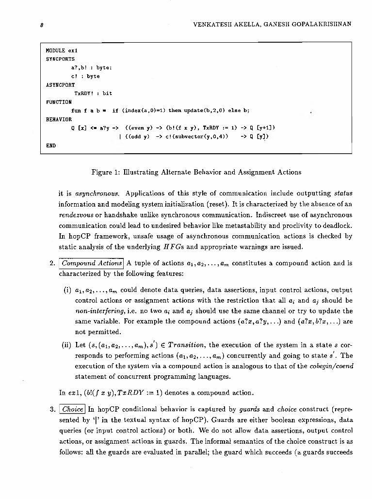
E x a m p le 1
Figure 1 describes a module e x l which declares T x R D Y as an output asynchronous channel and
a? and 6 ! as synchronous channels. / is a user-defined function used in the behavioral description. / is specified in a first-order functional language augmented with bit-vector manipulation routines. Informally, module e x l starts in a state (Q , [x]), engages in an data query a?y, and depending on
whether the input value y is even or odd it proceeds to perform the data assertion b l ( f x y ) and
an asynchronous output action T x R D Y := 1 and goes back to its initial control state Q with its
datapath state modified to the value denoted by y + 1 or performs c l (su b v e c to r (y , 0 ,4 )) and returns
to the initial control state Q with y as its datapath state. The behavior has the following features:
1. A ss ign m en t A ction apo := expr where apo £ A s y n c P o r t is an assignment action. In module
e x l , T x R D Y := 1 an assignment action which denotes the evaluation of the expression expr
(which is 1 in our example) and updating the asynchronous port T x R D Y . An assignment action does not have to synchronize with a receiver before transm itting the value. In this sense,
8 VENKATESH AKELLA, GANESH GOPALAKRISHNAN
MODULE exl
SYNCPORTS
a?,b! : byte;
c ! : byte
ASYNCPORT
TxRDY! : bit
FUNCTION
fun f a b = if (index(a,0)=l) then update(b,2,0) else b;
BEHAVIOR
Q [x] <■ a?y -> ((even y) -> (b!(f x y), TxRDY := 1) -> Q [y+1])
((odd y) -> c!(subvector(y,0,4)) -> Q [y]>
END
Figure 1 : Illustrating Alternate Behavior and Assignment Actions
it is asynchronous. Applications of this style of communication include outputting status
information and modeling system initialization (reset). It is characterized by the absence of an
rendezvous or handshake unlike synchronous communication. Indiscreet use of asynchronous
communication could lead to undesired behavior like m etastability and proclivity to deadlock. In hopCP framework, unsafe usage of asynchronous communication actions is checked by
static analysis of the underlying H F G s and appropriate warnings are issued.
2. C om pound A ctions A tuple of actions a i ,a 2 , . . . , a m constitutes a compound action and ischaracterized by the following features:
(i) a i , a 2 , . . . , a m could denote data queries, data assertions, input control actions, output control actions or assignment actions with the restriction that all a,- and aj should be non-interfering, i.e. no two a,- and aj should use the same channel or try to update the same variable. For example the compound actions (a 1 x ,a 1 y , . . . ) and ( a 1 x , b t x , . . . ) are
not permitted.
(ii) Let (s , (a i, a 2, . . . , am ), s') € T r a n s i t io n , the execution of the system in a state s corresponds to performing actions ( a i , a 2, . . . , a m) concurrently and going to state s . The execution of the system via a compound action is analogous to that of the cobegin/coend
statem ent of concurrent programming languages.
In e x l , ( b \ ( f x y ) , T x R D Y := 1) denotes a compound action.
3. Choice In hopCP conditional behavior is captured by guards and choice construct (represented by ‘| ’ in the textual syntax of hopCP). Guards are either boolean expressions, data queries (or input control actions) or both. We do not allow data assertions, output control
actions, or assignment actions in guards. The informal semantics of the choice construct is as
follows: all the guards are evaluated in parallel; the guard which succeeds (a guards succeeds
S P E C IF IC A T IO N A N D V A L ID A T IO N O F C O N T R O L IN T E N S IV E IC S IN H O P C P 9
MODULE ex2
SYNCPORT
a?,b! : byte;
b?,c! : byte
FUNCTION
fun f a b = if (index(a,0)=l) then update(b,2,0) else b;
fun g a b = if (index(a,0)=0) then update(b,2,0) else a;
BEHAVIOR
(P [xl] <= a?yl -> b! (f xl yl) -> P [yl])
I I(Q [x2] <= b?y2 -> c!(g x2 y2) -> q [y2])
END
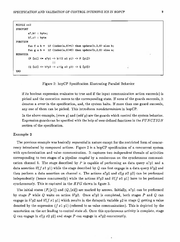
Figure 2: hopCP Specification Illustrating Parallel Behavior
if its boolean expression evaluates to true and if the input communication action succeeds) is
picked and the execution moves to the corresponding state. If none of the guards succeeds, it denotes a error in the specification, and, the system halts. If more than one guard succeeds, any one of them can be picked. This introduces nondeterm in ism in hopCP.
In the above example, (even y ) and (odd y) are the guards which control the system behavior. Expression guards can be specified with the help of user-defined functions in the F U N C T I O N
section of the specification.
E x a m p le 2
The previous example was basically sequential in nature except for the restricted form of concurrency introduced by compound actions. Figure 2 is a hopCP specification of a concurrent system
with synchronization and value communication. It captures two independent threads of activities corresponding to two stages of a pipeline coupled by a rendezvous on the synchronous communication channel b. The stage described by P is capable of performing an data query a l y l and a
data assertion &!(/ x l y l ) while the stage described by Q can first engage in a data query b1y2 and
then perform a data assertion on channel c. The actions a l y l and c\(g x2 y2) can be performed independently (hence concurrently) while the actions b1y2 and b \ ( f x l y l ) have to be performed
synchronously. This is captured in the H F G shown in figure 3.
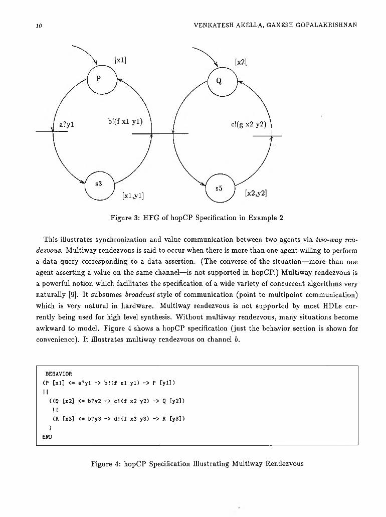
The initial states (P , [®1]) and ( Q , \ x 2]) are marked by arrows. Initially, a l y l can be performed
by stage P while Q waits on action b'!y2. Once a l y l is completed, both stages P and Q can
engage in b1y2 and &!(/ x l y l ) which results in the datapath variable y2 in stage Q getting a value
denoted by the expression ( f x l y l ) (referred to as value communication). This is depicted by the
annotation on the arc leading to control state .s5. Once this synchronous activity is complete, stage
Q can engage in cl(g x2 y2) and stage P can engage in a ly 2 concurrently.
10 VENKATESH AKELLA, GANESH GOPALAKRISHNAN
Figure 3: HFG of hopCP Specification in Example 2
This illustrates synchronization and value communication between two agents via two-way ren
dezvous. Mliltiway rendezvous is said to occur when there is more than one agent willing to perform
a data query corresponding to a data assertion. (The converse of the situation— more than one
agent asserting a value on the same channel—is not supported in hopCP.) Multiway rendezvous is
a powerful notion which facilitates the specification of a wide variety of concurrent algorithms very
naturally [9]. It subsumes broadcast style of communication (point to multipoint communication)
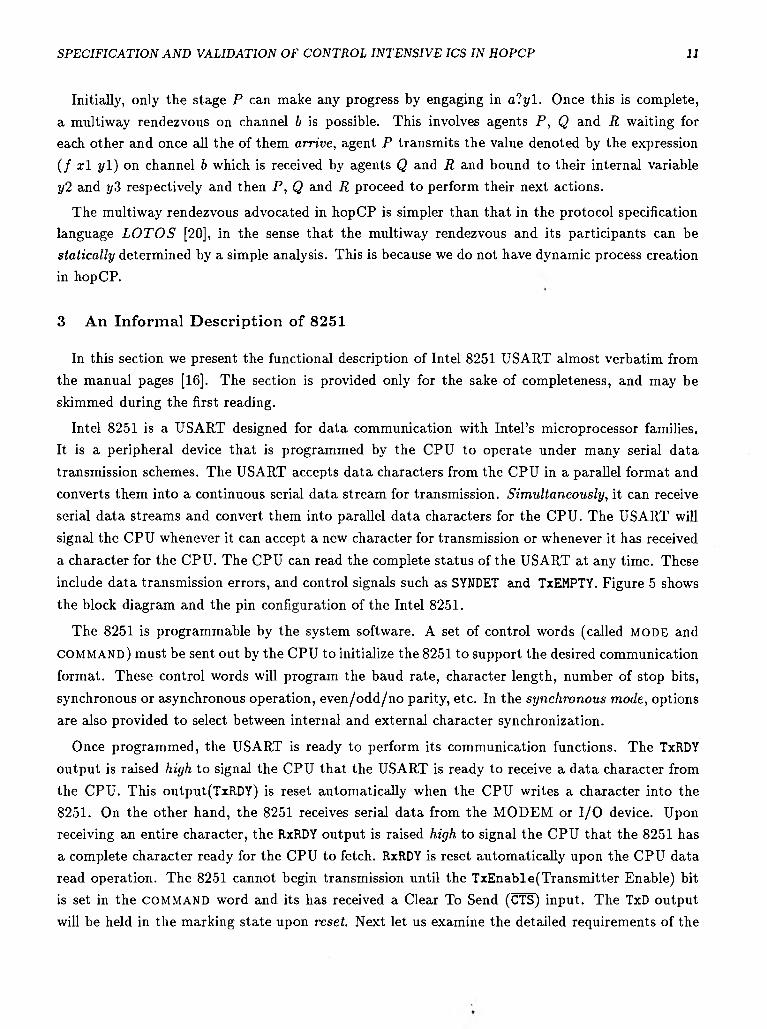
which is very natural in hardware. Multiway rendezvous is not supported by most HDLs cur
rently being used for high level synthesis. W ithout multiway rendezvous, many situations become
awkward to model. Figure 4 shows a hopCP specification (just the behavior section is shown for
convenience). It illustrates multiway rendezvous on channel b.
BEHAVIOR
(P [xl] <= a?yl -> b! (f xl yl) -> P [yl])
I I((Q [x2] <= b?y2 -> c!(f x2 y2) -> Q [y2])
I I(R [x3] <= b?y3 -> d!(f x3 y3) -> R [y3])
)END
Figure 4: hopCP Specification Illustrating Multiway Rendezvous
S P E C IF IC A T IO N A N D V A L ID A T IO N O F C O N T R O L IN T E N S IV E IC S IN H O P C P 11
Initially, only the stage P can make any progress by engaging in a l y l . Once this is complete, a multiway rendezvous on channel b is possible. This involves agents P , Q and R waiting for each other and once all the of them arrive , agent P transmits the value denoted by the expression
( / x l y l ) on channel b which is received by agents Q and R and bound to their internal variable y2 and y 3 respectively and then P , Q and R proceed to perform their next actions.
The multiway rendezvous advocated in hopCP is simpler than that in the protocol specification language L O T O S [20], in the sense that the multiway rendezvous and its participants can be s tatically determined by a simple analysis. This is because we do not have dynamic process creation
in hopCP.
3 A n In form al D escr ip tio n o f 8251
In this section we present the functional description of Intel 8251 USART almost verbatim from
the manual pages [16]. The section is provided only for the sake of completeness, and may be skimmed during the first reading.
Intel 8251 is a USART designed for data communication with Intel’s microprocessor families. It is a peripheral device that is programmed by the CPU to operate under many serial data
transmission schemes. The USART accepts data characters from the CPU in a parallel format and
converts them into a continuous serial data stream for transmission. Sim ultaneously , it can receive
serial data streams and convert them into parallel data characters for the CPU. The USART will signal the CPU whenever it can accept a new character for transmission or whenever it has received
a character for the CPU. The CPU can read the complete status of the USART at any time. These
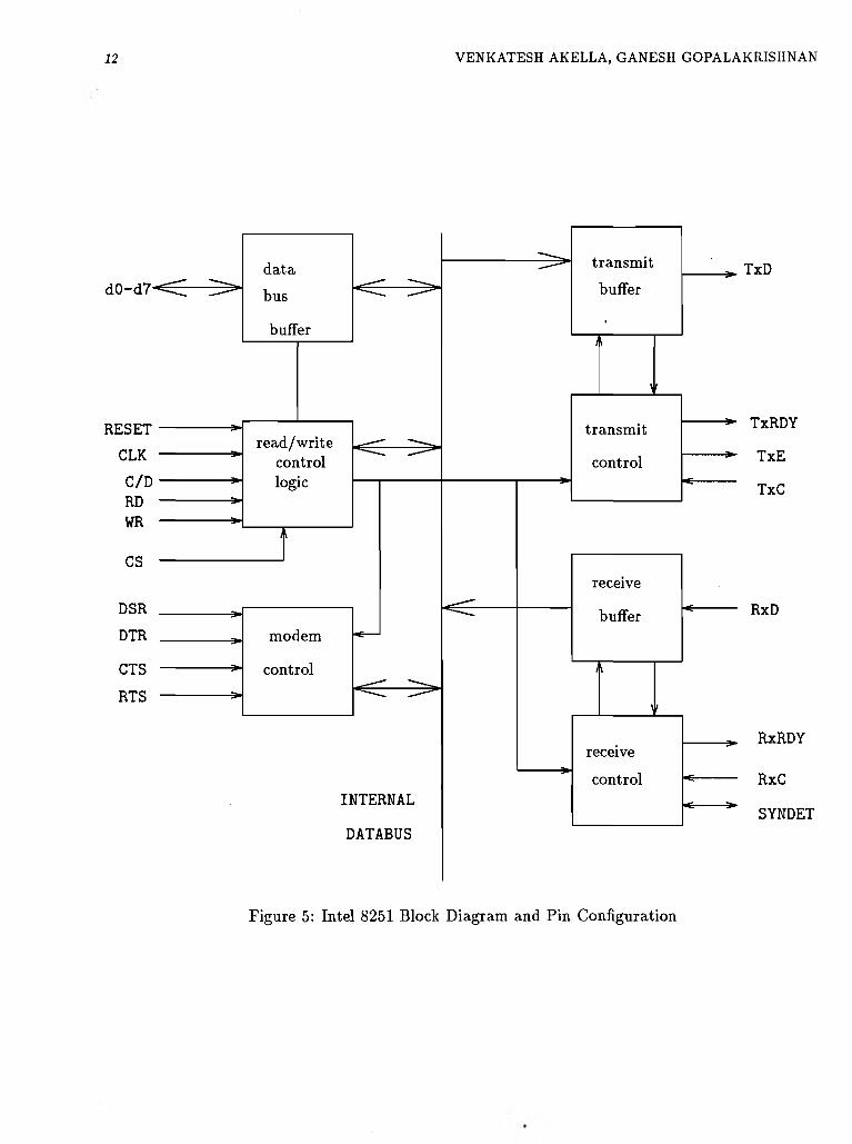
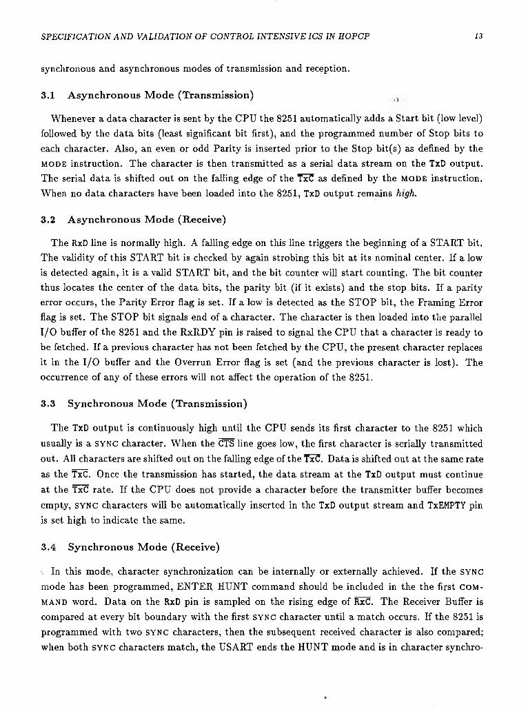
include data transmission errors, and control signals such as SYNDET and TxEMPTY. Figure 5 shows
the block diagram and the pin configuration of the Intel 8251.
The 8251 is programmable by the system software. A set of control words (called MODE and
COMMAND) must be sent out by the CPU to initialize the 8251 to support the desired communication
format. These control words will program the baud rate, character length, number of stop bits,
synchronous or asynchronous operation, even /odd/no parity, etc. In the synchronous mode , options
are also provided to select between internal and external character synchronization.
Once programmed, the USART is ready to perform its communication functions. The TxRDY
output is raised high to signal the CPU that the USART is ready to receive a data character from
the CPU. This output(TxRDY) is reset automatically when the CPU writes a character into the 8251. On the other hand, the 8251 receives serial data from the MODEM or I/O device. Upon receiving an entire character, the RxRDY output is raised high to signal the CPU that the 8251 has a complete character ready for the CPU to fetch. RxRDY is reset automatically upon the CPU data
read operation. The 8251 cannot begin transmission until the TxEnable(Transmitter Enable) bit is set in the COMMAND word and its has received a Clear To Send (CTS) input. The TxD output
will be held in the marking state upon reset. Next let us examine the detailed requirements of the
12 VENKATESH AKELLA, GANESH GOPALAKRISHNAN
Figure 5: Intel 8251 Block Diagram and Pin Configuration
S P E C IF IC A T IO N A N D V A L ID A T IO N O F C O N T R O L IN T E N S IV E IC S IN H O P C P 13
synchronous and asynchronous modes of transmission and reception.
3.1 A synchronous M ode (Transm ission)
Whenever a data character is sent by the CPU the 8251 automatically adds a Start bit (low level) followed by the data bits (least significant bit first), and the programmed number of Stop bits to
each character. Also, an even or odd Parity is inserted prior to the Stop bit(s) as defined by the m o d e instruction. The character is then transmitted as a serial data stream on the TxD output. The serial data is shifted out on the falling edge of the TxC as defined by the m o d e instruction. When no data characters have been loaded into the 8251, TxD output remains high.
3.2 A synchronous M ode (R eceive)
The ExD line is normally high. A falling edge on this line triggers the beginning of a START bit. The validity of this START bit is checked by again strobing this bit at its nominal center. If a low is detected again, it is a valid START bit, and the bit counter will start counting. The bit counter thus locates the center of the data bits, the parity bit (if it exists) and the stop bits. If a parity error occurs, the Parity Error flag is set. If a low is detected as the STOP bit, the Framing Error flag is set. The STOP bit signals end of a character. The character is then loaded into the parallel I/O buffer of the 8251 and the RxRDY pin is raised to signal the CPU that a character is ready to
be fetched. If a previous character has not been fetched by the CPU, the present character replaces
it in the I/O buffer and the Overrun Error flag is set (and the previous character is lost). The occurrence of any of these errors will not affect the operation of the 8251.
3.3 Synchronous M ode (Transm ission)
The TxD output is continuously high until the CPU sends its first character to the 8251 which
usually is a SYNC character. W hen the CTS line goes low, the first character is serially transmitted
out. All characters are shifted out on the falling edge of the TxC. D ata is shifted out at the same rate
as the TxC. Once the transmission has started, the data stream at the TxD output must continue
at the TxC rate. If the CPU does not provide a character before the transmitter buffer becomes
empty, SYNC characters will be automatically inserted in the TxD output stream and TxEMPTY pin
is set high to indicate the same.
3.4 Synchronous M ode (R eceive)
\ In this mode, character synchronization can be internally or externally achieved. If the SYNC
mode has been programmed, ENTER HUNT command should be included in the the first c o m
m a n d word. D ata on the RxD pin is sampled on the rising edge of RxC. The Receiver Buffer is
compared at every bit boundary with the first s y n c character until a match occurs. If the 8251 is programmed with two SYNC characters, then the subsequent received character is also compared; when both SYNC characters match, the USART ends the HUNT mode and is in character synchro
14 VENKATESH AKELLA, GANESH GOPALAKRISHNAN
nization. The SYNDET pin is set high and is reset by subsequent ST A T U S read operation. In the external SYNC mode, synchronization is achieved by applying a high level on the SYNDET pin, thus forcing the 8251 out of the HUNT mode. Parity and Overrun errors are checked in the same way
as above.
The COMMAND word controls the actual operation of the 8251 by issuing commands like Enable
Transm it/Receive, Error Reset and Modem Control and Internal Reset. The COMMAND instruction can be issued anywhere during data transmission while the m o d e instruction can be issued only after an internal or external reset. In a data communication environment it is necessary to examine the “status” of the active device to ascertain if errors have occurred or other conditions that require the processor’s attention. The 8251 has facilities that allow the programmer to “read” the status of the device at any time during the functional operation. Some of the bits of the STATUS word have identical meaning to the external output pins so that the 8251 can be used in a completely polled or interrupt-driven environment; the TxRDY signal is an exception.
4 Form al D escr ip tio n in h op C P
The above informal specification makes it clear that unless a precise and succinct notation is employed, the overall behavior of the 8251 will not be comprehensible for a user. We now discuss
a suitable logical organization of a hopCP specification of the 8251.
4.1 Logical Organization o f the Specification o f 8251
The specification of the Intel 8251 in hopCP raises the following issues:
• Partitioning:
It is not very useful to specify the whole 8251 as one monolithic hopCP module. It would not
capture the concurrency in the behavior accurately. Therefore we model it as a collection of
three independent processes: main which handles the CPU interface and the modem control,
xmit which describes the transmitter section which includes both the synchronous and asyn
chronous transmission modes and the associated status information, and rcvr which describes
the receiver section which includes both the synchronous and the asynchronous modes of
behavior.
• Logical Channels:
The xmit, rcvr and main execute concurrently and communicate with each other using syn
chronous and asynchronous ports. The communication channels used in the hopCP specification and the electrical pins of the 8251 (shown in figure 5) are not in direct correspondence.
Hence, we call the communication ports used in hopCP specification as logical channels. Several logical channels can be mapped into the same set of physical wire(s). This is useful in two ways:(i) it helps us to model bidirectional buses as two separate unidirectional logical
S P E C IF IC A T IO N A N D V A L ID A T IO N O F C O N T R O L IN T E N S IV E IC S IN H O P C P 15
channels since bidirectional buses are not allowed in hopCP and (ii) A time-shared bus like ( D o , D i , . . . , D 7 ) which is used to communicate data, status, and control from /to the CPU, is modeled as four separate logical (unidirectional) channels. This makes the specification clearer. Time-shared implementation can be derived in hopCP as an optimization. Derivation of circuits from hopCP is not discussed further in this paper.
• Handling Shared State:
COMMAND, MODE, STATUS and SYNC characters are variables common to xmit.rcvr, and main
processes, c o m m a n d , m o d e , and s y n c characters are written by the CPU and read by all the
three processes while STATUS is read by the CPU and written by xmit and rcvr processes. In
hopCP, shared variables like c o m m a n d , m o d e , and s y n c characters are handled by keeping
local copies of each variable in all the processes which read it and maintaining the consistency of the data by using m ultiway rendezvous. Multiway rendezvous ensures data consistency
because value is sent to all the processes needing the data at the same time, s t a t u s is
handled by keeping only one copy in the main process and having xmit and rcvr processes
send their individual status information to the main processes which does the update.
• Status Signals and Interrupt-driven Mode
Status signals like TxRDY (which announces that the transmitter section is ready to receive
the next character) and RxRDY (announcing the availability of next character) are modeled
in hopCP using asynchronous channels. Asynchronous communication actions do not need synchronization, they involve asserting a value on the associated channel. This enables us
to model in terrupt-driven modes of behavior, because TxRDY/RxRDY could be connected to
the interrupt lines of the CPU. If so, a status output on TxRDY/RxRDY could trigger the corresponding interrupt-handier in the CPU.
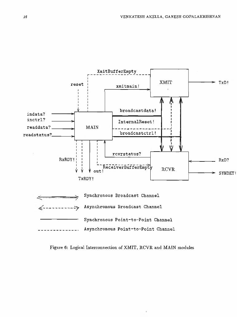
xmit.rcvr, and main are implemented by the hopCP modules XM IT, RCVR, and MAIN modules, which are discussed in detail next. The logical interconnection of the three modules is shown in
figure 6 .
4.2 M ain M odule
The specification has six sections as described earlier.
Module MAII
Type
byte vector 8 of b i t ;
Bit: vector 1 of bit
The first two sections shown above specify the name of the module and the types of the various
communication channels.
16 VENKATESH AKELLA, GANESH GOPALAKRISHNAN
Synchronous Broadcast Channel~7
___________ zy , Asynchronous Broadcast Channel
-----------------Synchronous Point-to-Point Channel
__________________Asynchronous Point-to-Point Channel
Figure 6: Logical Interconnection of XMIT, RCVR and MAIN modules

S P E C IF IC A T IO N A N D V A L ID A T IO N O F C O N T R O L IN T E N S IV E IC S IN H O P C P 17
SyncPort
indata?, inctrl?.rcvrmain?, rcvrstatus? : byte;
broadcastdata!, broadcastctrl!, out!, xmitmain! : byte;
indata!, inctrl!, rcvrmain!, readdata!, readstatus!,rcvrstatus! : byte;
readdata?, readstatus?, intReset! : Bit
AsyncPort
reset? : Bit;
reset! : Bit;
TxRDY!, RxRDY! : Bit;
XmitBufferEmpty!, ReceiverBufferEmpty!.extReset! : Bit
The S yn cP ort section describes the synchronous com m unication channels used in the specifica
tion. in d a t a ? , i n c t r l ? are input channels which carry data and control inform ation from the
CPU while o u t! is the output channel which carries data and status inform ation to the CPU.
rea d d a ta ? and r e a d s t a tu s ? are input control channels (only synchronization, no value com
m unication) through which the CPU in itiates a data or status read operation, b r o a d c a s td a ta
and b r o a d c a s t c t r l are internal channels which broadcast m o d e and c o m m a n d words to XMIT
and RCVR m odules using m ultiw ay rendezvous, rcvrm ain and xm itm ain are internal chan
nel to receive statu s inform ation from RCVR m odule and send data to XMIT m odule respec
tively. T he A syn cP ort section describes the asynchronous channels (shared variables) used in
the specification, r e s e t and statu s outputs RxRDY and TxRDY are m odeled as bit-valued asyn
chronous ports. X m itB ufferE m pty, in t R e s e t , e x t R e s e t , R ece iv erB u fferE m p ty are internal
asynchronous ports which are w ritten by the MAIN m odule and read by the XMIT and RCVR m odules.
Function
fun IsTrue x ” if (x=l) then true else false endif;
fun IsFalse x = if (x-0) then true else false endif;
fun SyncMode x - if (subvector(x,0,l) - 0) then true else false endif;
fun ReadSync2 x ” if (subvector(x,7,7) * 0) then true else false endif;
fun InternalReset y “ if (subvector (y,6,6) * 1) then true else false endif;
fun UpdateStatus status nen.st * orb(status, nen.st)
The fu n c t io n section describes the user-defined functions used in the specification. They capture
the decoding of the m o d e words and assembling the s t a t u s words based on their format in [16]. Note that the functions are expressed in a first-order functional language with built-in routines for bit-level manipulations, s u b v e c to r ( x ,y ,z ) returns the value of the integer formed by the bits
18 VENKATESH AKELLA, GANESH GOPALAKRISHNAN
from y to z from the bitvector denoted by x while orb does a simple bitwise OR operation. For
example, s u b v e c to r ( 6 3 ,0 ,3 ) = 15 and o rb (6 ,5 ) = 7.
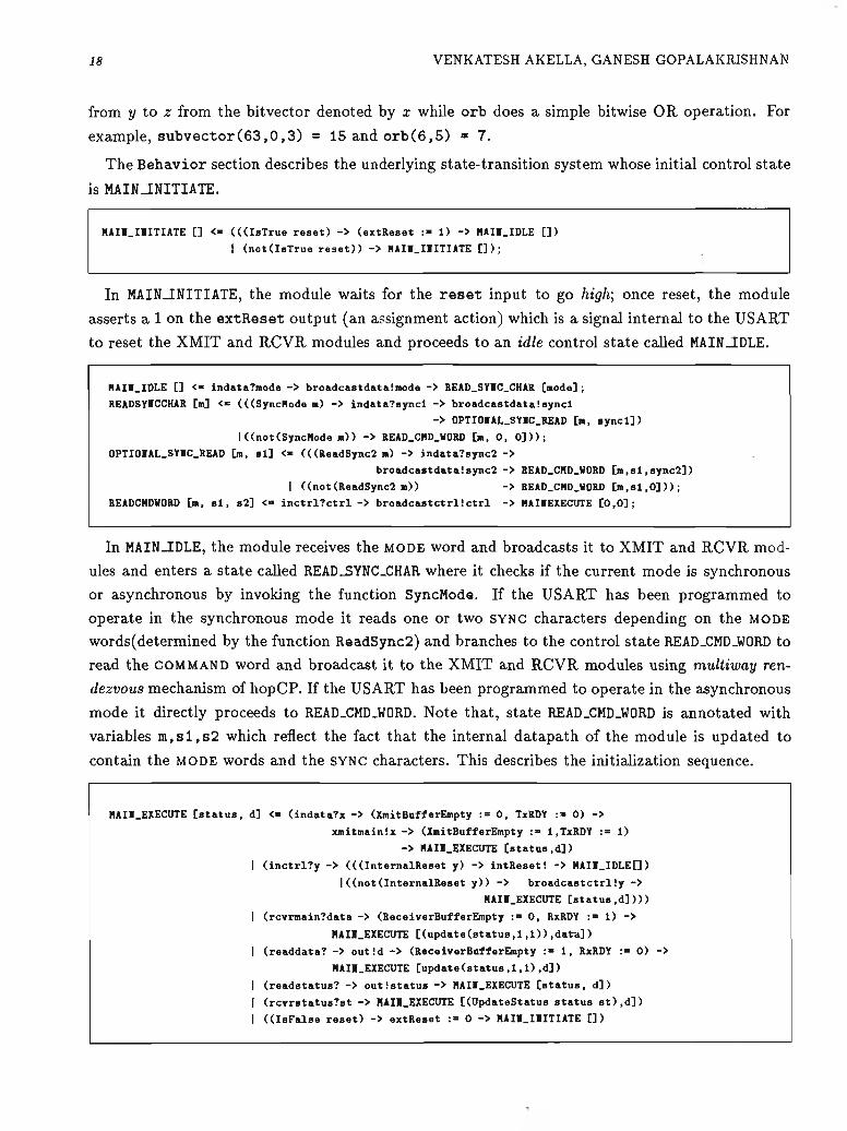
The B eh a v io r section describes the underlying state-transition system w hose initial control sta te
is MAIN_INITIATE.
HAII.IIITIATE [] <« (((IsTrue reset) -> (extReset :» 1) -> HAII.IDLE [])
j (not(IsTrue reset)) -> HAII_IIITIATE [] );
In MAIN_INITIATE, the module waits for the r e s e t input to go high] once reset, the module
asserts a 1 on the e x tR e s e t output (an assignment action) which is a signal internal to the USART
to reset the XMIT and RCVR modules and proceeds to an idle control state called MAIN_IDLE.
HAII.IDLE [] <“ indata?mode -> broadcastdataimode -> READ.SYIC.CHAR [mode];
READSYICCHAR [m] <“ (((SyncMode m) -> indata?syncl -> broadcastdata!syncl
-> OPTIOIAL.SYIC.READ [m, syncl])
I((not(SyncMode m)) -> READ.CHD.WORD [m, 0, 0]));
OPTIOIAL.SYIC.READ [m, si] <- (((ReadSync2 m) -> indata?sync2 ->
broadcastdata!sync2 -> READ.CHD.WORD [m,sl,sync2])
I ((not(ReadSync2 m)) -> READ.CHD.WORD [m,sl,0]));
READCHDWORD [m, si, s2] <■» inctrl?ctrl -> broadcastctrlictrl -> HAIIEXECUTE [0,0];
In MAIN -IDLE, the module receives the MODE word and broadcasts it to XM IT and RCVR modules and enters a state called READ_SYNC_CHAR where it checks if the current mode is synchronous or asynchronous by invoking the function SyncMode. If the USART has been programmed to operate in the synchronous mode it reads one or two s y n c characters depending on the m o d e
words(determined by the function ReadSync2) and branches to the control state READ_CMD_WORD to read the c o m m a n d word and broadcast it to the XMIT and RCVR modules using m ultiway ren
dezvous mechanism of hopCP. If the USART has been programmed to operate in the asynchronous mode it directly proceeds to READ_CMD_WORD. Note that, state READ_CMD_WORD is annotated with variables m , s l , s 2 which reflect the fact that the internal datapath of the module is updated to
contain the MODE words and the s y n c characters. This describes the initialization sequence.
HAII.EXECUTE [status, d] <= (indata?x -> (XmitBufferEmpty := 0, TxRDY := 0) ->
xmitmainix -> (XmitBufferEmpty : = 1,TxRDY : = 1)
-> HAII.EXECUTE [status,d])
I (inctrl?y -> (((InternalReset y) -> intReset! -> HAII_IDLE[])
I((not(InternalReset y)) -> broadcastctrl!y ->
HAII.EXECUTE [status,d])))
I (rcvrmain?data -> (ReceiverBufferEmpty := 0, RxRDY := 1) ->
HAII.EXECUTE [(update(status,1,1)),data])
I (readdata? -> outld -> (ReceiverBufferEmpty := 1, RxRDY := 0) ->
HAII.EXECUTE [update(status ,1,1),d])
I (readstatus? -> out{status ~> HAII.EXECUTE [status, d ] )
I (rcvrstatus?st -> HAII.EXECUTE [(UpdateStatus status st),d])
I ((IsFalse reset) -> extReset := 0 -> HAII.IIITIATE [])
S P E C IF IC A T IO N A N D V A L ID A T IO N O F C O N T R O L IN T E N S IV E IC S IN H O P C P 19
The fragment of hopCP code shown above, denotes the execution loop of the USART. It is
expressed using the nondeterm in is tic choice construct of hopCP. In the state MAIN_EXECUTE, the
USART either receives the data from the CPU and transmits to the XMIT module, or receives a
request to read status or data from the CPU wherein it sends the available data or status on out
channel. It is also capable of receiving status updates from the RCVR module and receiving further
c o m m a n d words from the CPU. If the internal reset command is issued by the CPU anytime, the module resets the XMIT and RCVR modules through the in tR e se t channel and branches back to
MAIN_IDLE.
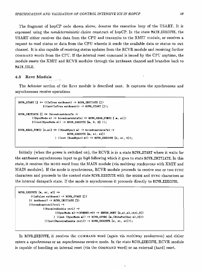
4.3 R cvr M odule '
The behavior section of the Rcvr module is described next. It captures the synchronous and asynchronous receive operations
RCVR.START [] <= ((IsTrue extReset) -> RCVR.IIITIATE [])
I ((notdsTrue extReset)) -> RCVR.START [] );
RCVR.IIITIATE [] <* (broadcastdata?m ->
((SyncHode m) -> broadcastdata?sl -> RCVR_READ_SYVC2 [ m, si])
I((not(SyncHode m ) ) -> RCVR.EXECUTE [ra, 0, 0] ));
RCVR.READ.SYIC2 [m,sl] <= ((ReadSync2 m) -> broadcastdata?s2 ->
RCVR.EXECUTE [m, si, s2])
I ((not (ReadSync2 m ) ) -> RCVR_EXECUTE [m, si, 0]);
Initially (when the power is switched on), the RCVR is in a state RCVR-START where it waits for
the e x tR e s e t asynchronous input to go high following which it goes to state RCVR-INITIATE. In this
state, it receives the m o d e word from the MAIN module (via multiway rendezvous with XMIT and MAIN modules). If the mode is synchronous, RCVR module proceeds to receive one or two s y n c
characters and proceeds to the control state RCVR_EXECUTE with the MODE and s y n c characters as
the internal datapath state. If the mode is asynchronous it proceeds directly to RCVR_EXECUTE.
RCVR.EXECUTE [m, si, s2] <=
((IsFalse extReset) -> RCVR.START [])
|< intReset? -> RCVR.IIITIATE [])
I (broadcastctrl?ctrl ->
((ReceiveEnable Ctrl) ->((SyncHode m)->(SYIDET:=0) -> EITER.HUIT [m,sl,s2 ,ctrl,0])
I ((not (SyncHode m ) ) -> RCVR.ASYIC [m,(BitsPerChar m ) ,0]))
I((not(ReceiveEnable Ctrl)) -> RCVR.EXECUTE [m, si, s2]));
In RCVR.EXECUTE, it receives the c o m m a n d word (again via multiway rendezvous) and either
enters a synchronous or an asynchronous receive mode. In the state RCVR.EXECUTE, RCVR module
is capable of handling an internal reset (via the c o m m a n d word) or an external (hard) reset.

20 VENKATESH AKELLA, GANESH GOPALAKRISHNAN
EITER_HUIT [mode, synl, syn2, Ctrl, rxbuffer] <« RxD?din ->
CHECK.FOR.SYBC.CHARl [mode, synl, syn2, Ctrl,
(AccumulateSerialData rxbuffer din)] ;
EITER_HUIT2 [mode, synl, syn2, Ctrl, rxbuffer] <“ RxDTdin ->
CHECK.F0R.SYBC.CHAR2 [mode, synl, syn2, Ctrl,
(AccumulateSerialData rxbuffer din)] ;
CHECK.FOR.SYBC.CHARl [m, si, s2, Ctrl, rxb] <■
((IsFalse extReset) -> RCVR.START [])
I(intReset? -> RCVR.IBITIATE [])
|((rxb»sl) -> ,
((ReadSync2 m) -> EBTER.HUBT2 [m, si, s2, Ctrl, 0])
I((not (ReadSync2 m)) -> SYIDET :« 1 ->
RCVR.ASYBC [m, (BitsPerChar m ) , 0]))
I((not (rxb=sl)) -> EBTER.HUBT [m, si, s2, Ctrl, rxb]);
CHECK_F0R_SYBC_CHAR2 [m, si, s 2 , Ctrl, rxb] <«
((IsFalse extReset) -> RCVRSTART [])
I(intReset? -> RCVRIIITIATE [] )
|((rxb=s2)-> SYBDET:=l-> RCVRASYBC[m,(BitsPerChar m ) , 0])
I((not (rxb=sl)) -> EBTER.HUBT2 [m, si, s2, Ctrl, rxb])
In the synchronous receive m ode, the m odule first enters a huntmode where it scans the incom ing
data for the synchronization characters and then proceeds to the control s ta te RCVR.ASYNC to
receive the serial data. In the asynchronous receive m ode, it directly proceeds to the control sta te
RCVR-ASYNC.
RCVR.ASYBC [mo, size, data] <=
((not(size=0)) -> RxD?y ->
RCVR.ASYBC [mo, (Decrement size), (AccumulateSerialData data y)])
I((size =0) -> RxDTpin ->
RCVR_PROCESS_DATA [mo, data, (CheckParityError data mo pin)]);
RCVR_PROCESS_DATA [mo, data, perror] <=
((IsFalse extReset) -> RCVR.START [])
I(intReset? -> RCVR.IHITIATE [])
I(RxD?sb ->((sb=0) -> SEBD.DATA_TO.HAIB [mo, data, perror, 1])
|((sb=l) -> SEHD_DATA_TO_HAIB [mo, data, perror, 0]));
SEBD.DATA_TO.MAIB [mode, data, pe, fe] <*
((IsFalse extReset) -> RCVR.START [] )
I(intReset? -> RCVR.ISITIATE [])
|((IsTrue ReceiverBufferEmpty) ->
rcvrstatus!(HakeAsyncStatus pe fe 0 1)
-> rcvrmainidata -> RCVR.EXECUTE [mode,0,0])
I ((not(IsTnie ReceiverBufferEmpty)) ->
rcvrstatus!(HakeAsyncStatus pe fe 1 1)
-> rcvrmainidata -> RCVR.EXECUTE [mode,0,0]);
In RCVR_ASYNC, RCVR module receives the specified number of bits serially on the RxD input. The number of bits is programmable by the CPU and is computed by the function Bitsperchar. The received serial data is checked for framing and parity errors as dictated by the COMMAND and MODE words. Then the data is sent to the MAIN module in parallel via a data assertion on the internal channel rcvrmain!. In the process it checks for overrun error. Note that we use the same mechanism to perform the synchronous and asynchronous receive operations. This is because in hopCP only the sequence-domain relationships between a set of actions is specified, no specific timing discipline (except causality) is advocated. This makes hopCP specifications smaller and
more abstract. After transmitting the data to the MAIN module, the RCVR module assembles the
status information (the state of fe,oe,pe,RxRDY bits), and sends it to the MAIN module using the rcvrstatus channel. The MAIN module can communicate the status information to the CPU.
The detailed hopCP specification of the XMIT module is presented in the appendix (to conserve
space). The behavior section resembles that of the RCVR module: Initially, XMIT module is in
state XMIT_START where it waits for a reset signal (from the MAIN module) and then receives
the m o d e word and c o m m a n d (via multiway rendezvous with RCVR and MAIN modules). If
the current operating mode is synchronous, XMIT module receive one or two synchronization
(depending on the output of the ReadSync2 function), receives the input character from the MAIN
module (in parallel) on the xmitmain channel and transmits it serially on the output port TxD. If a
new character is not received at the end of transmission of the current character, TxEMPTY pin is set high and SYNC characters are transmitted on TxD. In the asynchronous mode, the input character
is received from the MAIN module, padded with start and stop bits and shifted out serially (least
significant bit first) on the TxD output at a rate determined by the baud rate setting in the MODE
Intel 8251 has been specified in HardwareC [18] and a variant of ISPS [29]. The specifications are available with the distribution of high-level synthesis benchmarks. In this section we will compare the hopCP specification of the 8251 with its HardwareC and ISPS specifications. We will also touch upon the drawbacks of describing the 8251 in a language like Occam [8] which has been advocated
ISPS is a procedural language augmented with constructs to describe synchronous hardware. The significant differences between hopCP and ISPS specifications are that the ISPS specification(i) lacks abstraction in the sense that it describes on particular implementation of the 8251, based on synchronization flip-flops (ii) does not have constructs to expressing parallel behavior explicitly.
S P E C IF IC A T IO N A N D V A L ID A T IO N OF C O N T R O L IN T E N S IV E IC S IN H O P C P 21
22 VENKATESH AKELLA, GANESH GOPALAKRISHNAN
(iii) the computation is described in a imperative language.
4.5.2 HardwareC
The language hardwareC [18] comes closest to hopCP in terms of the communication constructs it
uses. This is encouraging because starting from similar motivations about the real-world scenarios
that we wish to model, we have independently ended up selecting the same set of communication
constructs in our respective HDLs. However, hardwareC is currently used to capture synchronous
computations only. In addition, hopCP is much simpler and is semantically well specified. Some
of the key differences between hardwareC and hopCP are as follows:
(i) HardwareC is a synchronous hardware description language, so it does not provide the same
temporal abstraction as hopCP. Specifications in hopCP can be implemented as purely synchronous
circuits, purely asynchronous circuits or a mixture of both. In addition, in a hopCP specification we
do not make any assumptions about the representation of the electrical signals i.e. we allow both transition based or level-based implementations— two popular styles of implementing asynchronous
circuits [28].
(ii) HardwareC is based on an imperative language to specify computation where parallelism has to be extracted from sequential descriptions (during synthesis) while hopCP is based on afunctional language the parallelism is implicit in the program (i.e. it is much easier to extract). In addition, the referential transparency of functional languages facilitates formal reasoning and proving properties about the system which are generally difficult in imperative languages. However, HardwareC has the ability to specify resource and timing constraints which are not provided in hopCP, at present.
4.5.3 CSP based Languages
CSP based languages like Occam used in [8] and Trace Theory used in [11] have the disadvantage of supporting only synchronous message passing. It is awkward to model asynchronous phenomena like interrupts and status and reset operations in such languages which makes them restrictive for
hardware specification. There are operators suggested in [15] to correct this defficiency but they are yet to appear in a realistic HDL.
5 T oo ls for A n a ly s is o f h op C P S p ec ifica tio n s
High-Level specifications of complex protocols are of little use if they are not adequately sup
ported by tools to analyze them and reason about them. In the hopCP design environment we
provide three different types of tools to support high-level specification:
• A suite of static analysis tools to perform reachability and seriality analysis on the H F G s .
• A behavioral inference tool called parC om p which infers the composite behavior of a collection
of hopCP modules.
S P E C IF IC A T IO N A N D V A L ID A T IO N O F C O N T R O L IN T E N S IV E IC S IN H O P C P 23
• A compiled-code behavioral simulator to establish functional correctness of the hopCP spec
ifications.
In section 5.1, we introduce the algorithm p a r C o m p . In section 5.2, we will briefly introduce
the seriality-checking algorithm. These algorithms have been detailed in [3]. Section 5.3 presents
the compiled code functional simulator that can be used to debug hopCP descriptions. Section 5.4 presents how hopCP specifications are debugged using tester processes.
5.1 Behavioral Inference via Parallel Com position
In this section we will briefly introduce p a r C o m p and discuss its performance on the USART example. We specified the USART as a collection of three independent modules MAIN, XMIT and RCVR. It is useful to have the composite (also known as inferred behavior) of the complete USART for several reasons. Inferred behavior can be used in high-level simulation, flow analysis of the hopCP specifications, and in formal verification. In this section we will describe a tool called p a r C o m p to derive the composite behavior of a set of modules specified in hopCP. Modules in liopCP interact via communication actions (data assertions and data queries). p a r C o m p infers
the behavior of a collection of hopCP modules by composing the individual transitions in the
H F G s of the constituent modules. Composing transitions involves checking for synchronization
and performing value communication. Transitions ty = ( { s i } ,a i , {s^}) and t 2 = ( { 5 2 }, 0 -2 , {^2 }) are said to synchronize if (i) ay and a 2 are mutually complementary (i.e. one is a data assertion and
the other is a data query) and (ii) they use the sam e communication port. For example, if ay = 6?x
and a 2 = b!e, ty and t 2 will synchronize and the resultant transition is 1 3 = ( { s i , s 2 }>0 2 > where the s'y = s'y[E[e\/x\ (E[e] denotes the value of the expression e evaluated in 5 2 ). The latter illustrates value communication.
If ay and a 2 do not synchronize, then transitions fi and t 2 are retained in the inferred behavior.
This is a significant difference compared to the other option of handling concurrent actions, namely,
nondeterm in is tic interleaving of the actions ay and a 2 in the inferred behavior. The interleaving of
actions ay and a 2 results in having transitions t y t2 and t 2ty in the inferred behavior which has the
capability of performing ay and a 2 in any order. This approach is taken in CSP and CSP based
languages. Our approach to handling concurrency results in a very efficient (both in time and
space) implementation of p a r C o m p when compared to the interleaved mode. On an average, the
number of states in the inferred behavior is a linear function of the number of states in the input
H F G s .
Note that, in the above example ay and a 2 are primitive actions. The notion of synchronization
and value communication can be extended in a similar way to compound actions. The details of semantics of p a r C o m p are presented in [2]. p a r C o m p has been implemented in Standard ML of New Jersey [4] in the prototype hopCP design environment on a SUN sparcstation. The statistics
of running p a r C o m p on the USART example are shown in figure 7. Note that the space and time requirements are fairly impressive considering the size of the example.
24 VENKATESH AKELLA, GANESH GOPALAKRISHNAN
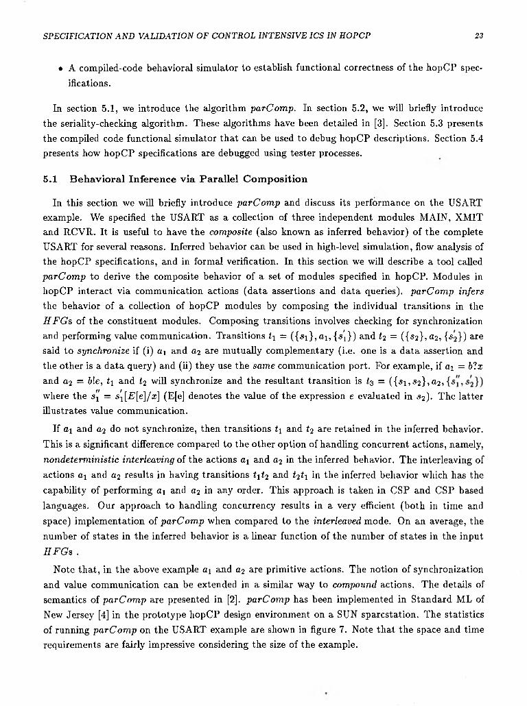
Circuit # Sta tes # Transitions T im e (secs)
1 UsartMain || UsartXmit || UsartRcvr 136 136 79.38
2 CpuMain || ExtRcvr || ExtXmit 15 15 0.33
3 UsartMain || UsartXmit || UsartRcvr || CpuMain || ExtRcvr || ExtXmit 166 154 141.42
Figure 7: Performance of Algorithm p a r C o m p on USART Specification
5.2 Seriality Checking and its Uses
Determining whether two specific actions of an HFG are serial or are potentially concurrent has numerous applications. This check can be used to warn if the asynchronous ports are not being used safely i.e. if there are conflicting reads/writes on the shared registers implementing the asynchronous ports. The seriality checking procedure can also be used to establish determ inacy of
guards in some situations and reveal opportunities for resource sharing. These optimization hints can be used in the high-level synthesis of VLSI circuits from hopCP specifications.
However, in a distributed environment with several concurrent processes, determining whether
two actions are potentially concurrent or not, automatically, is often difficult to formulate and
computationally expensive. There are essentially two problems.
Naive approaches to the detection of seriality can either lead to combinatorial explosion or can miss many opportunities to detect serial usage. Combinatorial explosion can result because many
of the techniques to detect seriality are centered around reachability analysis paradigm. These
problems are tackled in the hopCP framework by restricting the hopCP flow graphs to be one-safe
and employing a heuristic-based pruning of the composite hopCP flow graphs.
The second, and a more serious problem underlying the feasibility of the above optimizations, is
that unless the context (environment) of a module is known, it is not possible to tell if two actions
within the module definition are serial or not. For this to be done properly, we need a tool to
analyze the combined executions of a collection of processes that constitu tes the sys tem description,
and that, perhaps, even includes a process to model the abstracted environm ent. The algorithm
p a r C o m p outlined in the previous section is appropriate for this task.
Briefly, our seriality-checking procedure involves three phases: First, we invoke p a r C o m p to infer the composite behavior of the collection of hopCP modules. Then we derive an abstract H F G by
invoking the pruning heuristic on the inferred behavior with respect to the actions in question. The pruning heuristic rem oves uninteresting states and transitions with respect to the actions in
question. The third phase involves computing the set of reachable configurations from the initial states and determining if the two actions in questions can be enabled simultaneously or not. All the phases of the seriality-checking procedure have been formalized and implemented in the hopCP
design environment. The details are presented in [3].
This procedure was particularly useful on the USART specification because of its complexity.
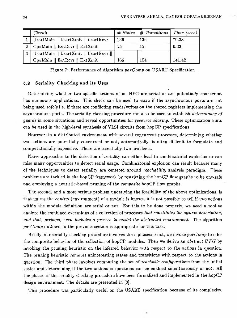
S P E C IF IC A T IO N A N D V A L ID A T IO N OF C O N T R O L IN T E N S IV E IC S IN H O P C P 25
Circuit Typical Running Time (secs) for a pair of randomly chosen actions
1 2-Stage Pipeline Unit 0.02
2 Mutex 0.05
3 UsartMain 0.184 UsartXmit 0.435 UsartRcvr 0.40
6 UsartMain || UsartXmit || UsartRcvr 12.097 CpuMain || ExtRcvr || ExtXm it 0.04 ,
Figure 8: Typical Performance of the Seriality Detection Procedure
Several errors in the unsafe usage of the asynchronous ports were revealed. In addition we also discovered that the in practice we do not need separate channels for in d a ta ? , i n c t r l ? , readdata? and r e a d s ta tu s? because they are never used concurrently. So, in an actual circuit implementation one could use a single multiplexed bidirectional channel to implement these four channels. This optimization is almost impossible to detect by manually analyzing the specifications of the XM IT, MAIN and RCVR modules. Typical running times of the seriality-checking procedure for
a varietly of examples including the US ART are shown in figures 8.
We also discovered that a slight modification of the seriality-checking procedure could be used
to detect the l iveness of the specification. Dead-states can be flagged during the generation of reachable configurations.
5 .3 CFSIM : A c o m p ile d -c o d e co n cu rren t fu n c tio n a l s im u la to r
A high-level specification is not very useful unless it is supported by a methodology to validate
it. There are usually two ways of validating a specification: (i) prove liveness and safety properties
of the specification [19]; and (ii) high-level simulation. We follow the second approach. We provide
a simulation environment called CFSIM to validate hopCP specifications. In this section we will
briefly outline the design of CFSIM and bring out some of its advantages and in the next section
we describe how some of the modes of behavior of the US ART specification are validated using CFSIM.
CFSIM is compiled-code concurrent functional simulator for hopCP specifications obtained by
translating H F G s into CML (Concurrent ML) source code. The details of C FSIM are described
in [1]. CML is an extension to Standard ML of New Jersey to support first-class synchronous operations [23]. CML being higher-order facilitates building concurrent-programming abstractions
and is implemented efficiently capitalizing on the continuation-passing style technology of the SML
of New Jersey compiler [5].
The first step in the generation of the simulator in CML is to decompose the hopCP specifications
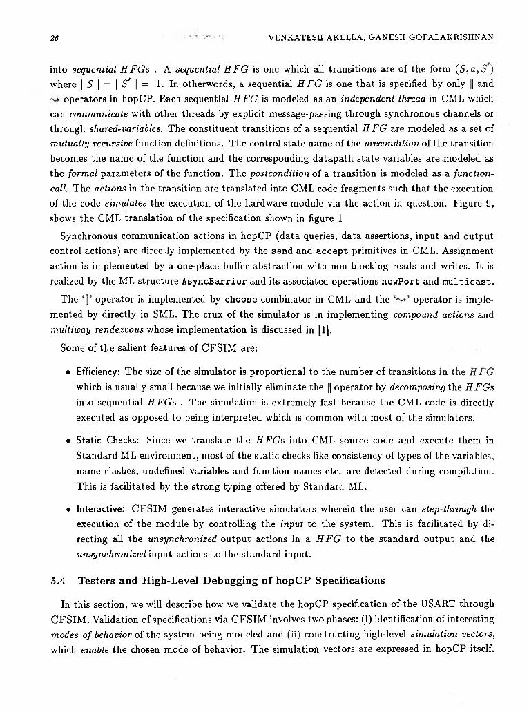
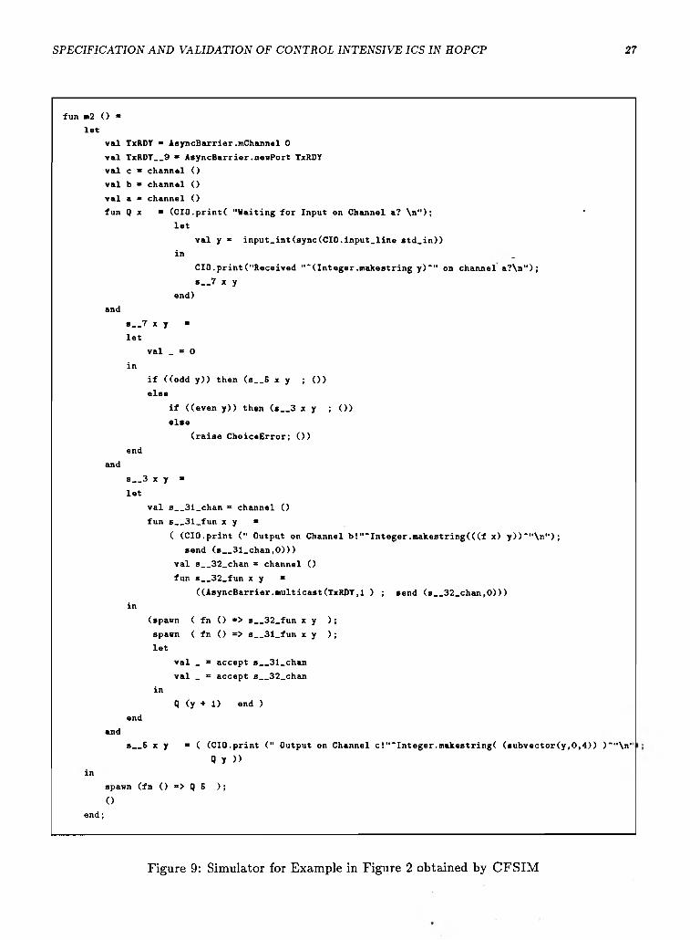
26 VENKATESH AKELLA, GANESH GOPALAKRISHNAN
into sequential H F G s . A sequential H F G is one which all transitions are of the form (S , a , S ) where | S | = | S' \ = 1. In otherwords, a sequential H F G is one that is specified by only |] and
operators in hopCP. Each sequential H F G is modeled as an independent thread in CML which can com m unicate with other threads by explicit message-passing through synchronous channels or through shared-variables. The constituent transitions of a sequential H F G are modeled as a set of m utually recursive function definitions. The control state name of the precondition of the transition becomes the name of the function and the corresponding datapath state variables are modeled as the fo rm a l parameters of the function. The postcondition of a transition is modeled as a function-
call. The actions in the transition are translated into CML code fragments such that the execution of the code sim ulates the execution of the hardware module via the action in question. Figure 9, shows the CML translation of the specification shown in figure 1
Synchronous communication actions in hopCP (data queries, data assertions, input and output control actions) are directly implemented by the send and a ccep t primitives in CML. Assignment action is implemented by a one-place buffer abstraction with non-blocking reads and writes. It is
realized by the ML structure A syncB arrier and its associated operations newPort and m u lt ic a s t .
The operator is implemented by choose combinator in CML and the operator is implemented by directly in SML. The crux of the simulator is in implementing compound actions and
m ultiway rendezvous whose implementation is discussed in [1].
Some of the salient features of CFSIM are: ..........
• Efficiency: The size of the simulator is proportional to the number of transitions in the H F G
which is usually small because we initially eliminate the || operator by decomposing the H F G s
into sequential H F G s . The simulation is extremely fast because the CML code is directly
executed as opposed to being interpreted which is common with most of the simulators.
• Static Checks: Since we translate the H F G s into CML source code and execute them in
Standard ML environment, most of the static checks like consistency of types of the variables,
name clashes, undefined variables and function names etc. are detected during compilation.
This is facilitated by the strong typing offered by Standard ML.
• Interactive: C FSIM generates interactive simulators wherein the user can step-through the execution of the module by controlling the input to the system . This is facilitated by directing all the unsynchronized output actions in a H F G to the standard output and the unsynchronized input actions to the standard input.
5.4 Testers and High-Level Debugging of h o p C P Specifications
In this section, we will describe how we validate the hopCP specification of the USART through C FSIM . Validation of specifications via C FSIM involves two phases: (i) identification of interesting modes o f behavior of the system being modeled and (ii) constructing high-level sim ulation vectors,
which enable the chosen mode of behavior. The simulation vectors are expressed in hopCP itself.
S P E C IF IC A T IO N A N D V A L ID A T IO N OF C O N T R O L IN T E N S IV E IC S IN H O P C P 27
fun m2 O *
let
val TxRDY “ AsyncBarrier .mChannel 0
val TxRDY__9 » AsyncBarrier.newPort TxRDY
val c = channel ()
val b = channel ()
val a « channel ()
fun Q x ■ (CIO.print( "Waiting for Input on Channel a? \n"); '
let
val y « input_int(sync(CIO.input_line std_in))
in _
CIO.print("Received "‘(Integer.makestring y)*" on channel a?\n");
s__7 x y
end)
and
s__7 x y =
let
val _ = 0
in
if ((odd y)) then (s__5 x y ; ())
else
if ((even y)) then (s__3 x y ; ())
else
(raise ChoiceError; ())
end
and
s__3 x y =
let
val s__31_chan = channel ()
fun s__31_fun x y =
( (CIO.print (" Output on Channel b!"*Integer.nakestring(((f x) y))*"\n");
send (s__31_chan,0)))
val s__32_chan = channel O
fun s __32_fun x y =
((AsyncBarrier.multicast(TxRDY,1 ) ; send (s__32_chan,0)))
in
(spawn ( fn () «> s__32_fun x y );
spawn ( fn () => s__31_fun x y );
let
val _ = accept s__31_chan
val _ = accept s__32_chan
in
Q ( y + 1 ) end )
end
and
s__S x y » ( (CIO.print (" Output on Channel c !"“Integer.makestring( (»ubv«ctor(y,0,4)) )""\n"
Q y ))in
spawn (fn () »> Q 5 );
()e n d ;
Figure 9: Simulator for Example in Figure 2 obtained by CFSIM
28 VENKATESH AKELLA, GANESH GOPALAKRISHNAN
A hopCP specification which enables a particular mode of behavior is called a te s ter module.
Identification of interesting modes of behavior and construction of tester modules are illustrated
with respect to the US ART specification discussed earlier.
5.4.1 Tester Modules and Modes of Behavior
There is a close analogy between the design validation strategy suggested here and the conven
tional VLSI test generation. Modes of behavior are like faults and tester modules are like physical tester vectors (sequences of binary inputs).
A mode o f behavior of a system can be defined as a f in ite execution trace of the system involving
at least one input communication action and one output communication action. The input and
output communication actions in the execution trace give us the ability to control the system
execution and observe the response of the system , respectively. A execution trace consisting of
only internal actions is not a useful mode of behavior. Some of the useful modes of behavior in the
USART example are: receiving a character from the CPU and transm itting it on the serial output TxD in the synchronous mode, receiving a character on the serial input RxD and transmitting it in parallel to the CPU, hunting for the synchronizing characters in the synchronous mode receive etc.
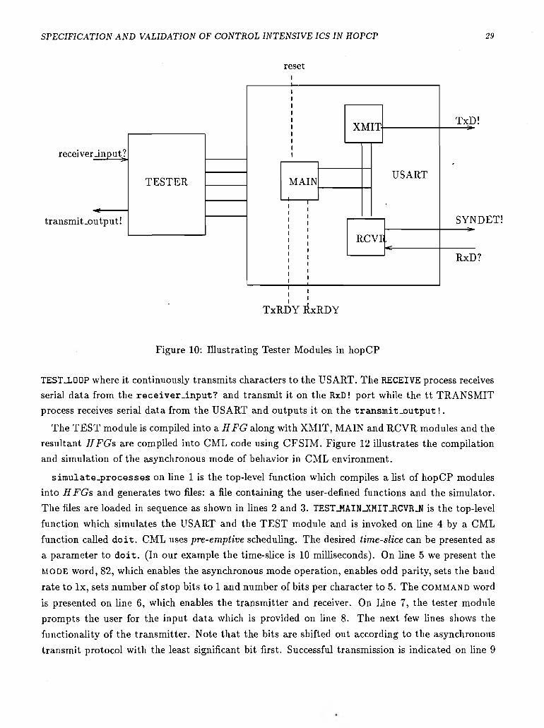
A te s ter module for a hopCP specification H is a hopCP description of a module which interacts with the system being tested (i.e. H ) and guides the execution of H along a chosen mode of behavior.
A tester module can be viewed as an interface between the user and the system under test as shown in figure 10. It receives the inputs from the user (via the CFSIM interactive environment) and provides the necessary stimulus to the system and it receives the responses from the system and channels them back to the user.
5.4.2 Illustrating Tester Modules
Let us consider validating the asynchronous mode of behavior of the USART specification. To recapitulate (from section 2), transmission in the asynchronous mode involves receiving a character
from the CPU and transm itting it serially on the TxD pin at a specified baud rate after padding it with a start bit and some specified number of stop bits and an optional parity bit. The baud rate, number of stop bits and kind of parity to be checked is specified by the m o d e word. Reception in
the asynchronous mode involves receiving a serial stream of data from the RxD input, and checking
for parity and framing errors and transmitting the character to the CPU.
A tester module called TEST which validates the asynchronous mode of behavior of the hopCP USART specification is shown in figure 11. It communicates with the user via synchronous ports
input_m ode?, input.command?, inp u t_d ata? , r e c e iv e r - in p u t? , and tr a n sm it .o u tp u t! and
communicates with the USART with the rest of the ports. TEST basically encapsulates three
concurrent processes which represent the CPU, and a serial transmitter and a serial receiver (denoting a Modem for example). TEST-RESET process, resets the USART via an assignment action
on the r e s e t port, and then loads the m o d e and COMMAND word. It then enters a state called
S P E C IF IC A T IO N A N D V A L ID A T IO N OF C O N T R O L IN T E N S IV E IC S IN H O P C P 29
reset
Figure 10: Illustrating Tester Modules in hopCP
TEST_L00P where it continuously transmits characters to the USART. The RECEIVE process receives serial data from the r e ce iv er _ in p u t? and transmit it on the RxD! port while the tt TRANSM IT process receives serial data from the USART and outputs it on the tra n sm it_ o u tp u t!.
The TEST module is compiled into a H F G along with XMIT, MAIN and RCVR modules and the resultant H F G s are compiled into CML code using CFSIM . Figure 12 illustrates the compilation and simulation of the asynchronous mode of behavior in CML environment.
s im u la te .p r o c e s se s on line 1 is the top-level function which compiles a list of hopCP modules into H F G s and generates two files: a file containing the user-defined functions and the simulator.
The files are loaded in sequence as shown in lines 2 and 3. TEST_MAIN_XMIT_RCVR_N is the top-level function which simulates the USART and the TEST module and is invoked on line 4 by a CML
function called d o it . CML uses pre-em ptive scheduling. The desired t ime-slice can be presented as
a parameter to d o it . (In our example the time-slice is 10 milliseconds). On line 5 we present the
m o d e word, 82, which enables the asynchronous mode operation, enables odd parity, sets the baud
rate to lx , sets number of stop bits to 1 and number of bits per character to 5. The COMMAND word
is presented on line 6, which enables the transmitter and receiver. On Line 7, the tester module prompts the user for the input data which is provided on line 8. The next few lines shows the
functionality of the transmitter. Note that the bits are shifted out according to the asynchronous
transmit protocol with the least significant bit first. Successful transmission is indicated on line 9
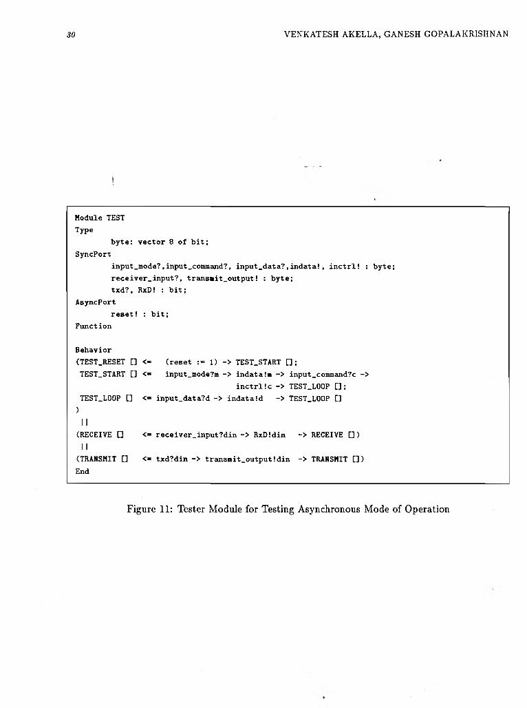
30 VENKATESH AKELLA, GANESH GOPALAKRISHNAN
j
Module TEST
Type
byte: vector 8 of bit;
SyncPort
input_mode?,input.command?, input_data?,indata!, inctrl! : byte;
receiver_input?, transmit_output! : byte;
txd?, RxD! : bit;
AsyncPort
reset! : bit;
Function
Behavior
(TEST_RESET [] <« (reset := 1) -> TEST.START [] ;
TEST_START [] <*= input_mode?m -> indata!m -> input_command?c ->
inctrl !c -> TEST.LOOP [] ;
TEST_L00P [] <= input_data?d -> indataid -> TEST.LOOP []
)I I
(RECEIVE [] <= receiver.input?din -> RxD!din -> RECEIVE [])
I I(TRANSMIT [] <= txd?din -> transmit_output!din -> TRANSMIT [])
End
Figure 11: Tester Module for Testing Asynchronous Mode of Operation
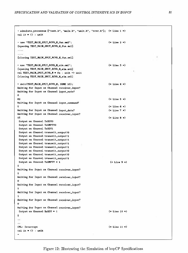
S P E C IF IC A T IO N A N D V A L ID A T IO N O F C O N T R O L IN T E N S IV E IC S IN H O P C P 31
- simulate.processes ["test.h", "main.h", "xmit.h", “rcvr.h"]; (* Lino 1 *)
val it = () : unit
- use "TEST.HAII.XHIT.RCVR.I.fun.sml";
[opening TEST_HAIB_XHIT_RCVR_B_fun.sml]
(* Line 2 *)
[closing TEST_HAIH_XHIT_RCVR_H_fun.sml]
- use "TEST_HAI8_XHIT.RCVR_I_sim.sml";
[opening TEST.HAIH.XHIT.RCVR.H.sim.sml]
val TEST.HAIH.XMIT.RCVR.I ■= fn : unit -> unit
[closing TEST.HAIH.XHIT.RCVR.H.sim.sml]
(* Line 3 *)
- doit(TEST.HAIH.XHIT.RCVR.I, SOHE 10);
Waiting for Input on Channel receiver.input?
Waiting for Input on Channel input.mode?
082
Waiting for Input on Channel input.command?
5
Waiting for Input on Channel input.data?
Waiting for Input on Channel receiver.input?
15
Output on Channel TxRDYO
Output on Channel TxEHPTYO
Output on Channel TxRDYl
Output on Channel transmit.output!0
Output on Channel transmit.output!1
Output on Channel transmit.output!1
Output on Channel transmit.output!1
Output on Channel transmit.output!1
Output on Channel transmit.output!0
Output on Channel transmit.output!0
Output on Channel transmit.output!1
Output on Channel TxEHPTY ■ 1
1Waiting for Input on Channel receiver.input?
1Waiting for Input on Channel receiver.input?
0Waiting for Input on Channel receiver.input?
1Waiting for Input on Channel receiver.input?
1Waiting for Input on Channel receiver.input?
0Waiting for Input on Channel receiver.input?
Output on Channel RxRDY ■ 1
1
(* Line 4 *)
(* Line 5 *)
(* Line 6 *)
(* Line 7 *)
(* Line 8 *)
(* Line 9 *)
(* Line 10 *)
CHL: Interrupt
val it = () : unit
(* Line 11 *)
Figure 12: Illustrating the Simulation of hopCP Specifications
32 VENKATESH AKELLA, GANESH GOPALAKRISHNAN
when TxEMPTY status flag is set. In parallel, receive operation is going on, whose termination is
detected by the status flag RxRDY on line 10. Since, the tester module was constructed to be an
infinite process, we terminate the simulation session by an interrupt shown on line 11.
5 .4 .3 D isc u ss io n
hopCP specification of the USART was checked for different modes of behavior like internal and
external reset operation, synchronous receive and transm it, setting of various error flags (overrun, parity, framing) and status flags TxRDY, RxRDY, TxEMPTY, SYNDET, external character synchronization, by constructing appropriate TESTER module. Actually something similar to conventional fault sim ulation was employed, in the sense that a single tester module was programmed
with appropriate m o d e words to check for more than one mode of behavior. Several errors were detected by this validation process which were subsequently fixed.
The attractive features of this style of validation process are:
• Testers are specified in the same HDL. This opens up several promising avenues for further research like extracting BIST (Built-in-Self-Test) hardware by syn thesizing the tester module just like the rest of the hopCP specification, including DFT (Design For Testability) ideas
in the specification i.e. writing a specification which when synthesized becomes more easily testable.
• We feel that te s ter modules provide a system atic and elegant approach to functional simulation, since most of the details of the simulation are buried within the tester module. The user does not have to deal directly with the specification as shown in figure 10.
• By expressing the te s ter module in hopCP and simulating it via C FSIM we are actually
validating our system in truly concurrent environment. This is illustrated in the example of
the tester module above (which validates the asynchronous mode of behavior). Note that the
tester itself has three concurrent processes. So, the validation of the USART in the CFSIM
environment has the effect of connecting an 8251 to a modem and a microprocessor and
switching on the power quite realistically.
6 Concluding Remarks
The major contributions of this work are: (i) Introduction of a simple HDL called hopCP to
describe concurrent state-transition systems. Specifications in hopCP are characterized by absence
of explicit timing discipline (except the causality of actions), functional sublanguage to specify
computational aspects and support for synchronous and asynchronous communication mechanisms.
We illustrate the expressive power of hopCP by capturing the behavior of a fairly complex chip
namely Intel 8251 as accurately as possible. We show the difficulties encountered in modeling a
chip such as Intel 8251 and how we address them in hopCP. (ii) A behavioral inference tool called
•parComp and its applications (iii) high-level validation of hopCP specifications via a compiled-code
concurrent functional simulator (C FSIM ) and a notion of tester modules.
In a nutshell the main contribution of this work is the demonstration of the applicability of formal methods in the specification and validation of a realistic and existing hardware design.
Currently we are engaged in systematically transforming hopCP specifications into VLSI circuits
with as little manual intervention as possible. We are also exploring the possibilities of augmenting hopCP with mechanisms to handle timing constraints and using CFSIM and its variants to perform
1. A k e l l a , V ., AND G o p a l a k r i s h n a n , G . CFSIM: A Compiled-Code Concurrent Functional Simulator for VLSI System s. Tech. rep., Department of Computer Science, University of Utah, 1991. In
2. A k e l l a , V ., a n d G o p a l a k r i s h n a n , G . hopCP: A Concurrent Hardware Description Language. Tech. Rep. UUCS-91-021, Department of Computer Science, University of Utah, Oct. 1991.
3. A k e l l a , V ., a n d G o p a l a k r i s h n a n , G . Static Analysis Techniques for the Synthesis of Efficient Asynchronous Circuits. Tech. Rep. UUCS-91-018, Department of Computer Science, University of Utah,
4. AP P EL , A . , AND M a c Q u e e n , D. A Standard ML compiler. In F unctional P rogram m ing Languages
5. A p p e l , A . W . C om pilin g with C on tin uations. Cambridge Univ. Press, 1992. ISBN 0-521-41695-7.
6. A p t , K . R ., a n d O l d e r o g , E .-R . Verification o f Sequen tia l and C on cu rrent Program s. Springer-
7. B a r b a c c i , M. R. Instruction Set Processor Specifications (ISPS): The N otation and Its Applications.
8. B r u n v a n d , E . T ran sla tin g C on cu rrent C om m un icatin g Program s in to A syn ch ron ou s C ircu its. PhD
9. C h a r l e s w o r t h , A . The Multiway Rendezvous. A C M T ran sactions on P rogram m ing Languages and
10. C l e v e l a n d , R ., P a r r o w , J ., a n d S t e f f e n , B . The concurrency workbench: A sem antics based tool for the verification of concurrent system s. Tech. Rep. ECS-LFCS-89-83, Laboratory for Foundations of
11. E b e r g e n , J. C. Translating Program s in to D elay In sen sitive C ircu its. Centre for M athematics and
12. G o p a l a k r i s h n a n , G . , a n d F u j i m o t o , R. Design and verification of the rollback chip using hop: A case study of formal m ethods applied to hardware design. Tech. Rep. UU-CS-TR-91-015, University of
S P E C IF IC A T IO N A N D V A L ID A T IO N OF C O N T R O L IN T E N S IV E IC S IN H O P C P 33
34 VENKATESH AKELLA, GANESH GOPALAKRISHNAN
13. H a l l , A . Seven m yths of formal m ethods. IE E E Softw are, 9 (Sept. 1990).
14. H a r ’E l , Z., a n d K u r s h a n , R. P . Software for analytical development of com m unication protocols. A T & T Technical Jou rnal (Jan. 1990). To appear.
15. H o a r e , C . A . R . C om m un icatin g Sequen tia l P rocesses. Prentice-Hall, Englewood Cliffs, New Jersey,
1985. , a c
16. 8251A Programmable Communication Interface. In In te l M icroprocessor and P eriph era l Handbook
(1986), pp. 6.122-6.138. •
17. J o h n s o n , S. D . S yn th esis o f D ig ita l D esigns fro m R ecursion E quations. The MIT Press, 1984. An ACM Distinguished Dissertation-1983.
18. K u, D ., a n d M i c h e l i , G. D . HardwareC - A Language for Hardware Design, Version 2.0. Tech. Rep. CSL-TR-90-419, Computer Science Laboratory, Stanford University, April 1990.
19. L a m p o r t , L . A Simple Approach to Specifying Concurrent System s. C om m u n ica tion s o f the A C M 32,
1 (Jan. 1989), 32-45.
20. L o g r i p p o , L . , O b a i d , A ., J . P . B r i a n d , a n d F e h r i , M . An Interpreter for LOTOS, a Specification Language for Distributed System s. S oftw are—P ractice and E xperience 18, 4 (Apr. 1988), 365-385.
21. M a r t i n , A . J ., B u r n s , S ., T . K . L e e , D . B o r k o v i c , a n d P . J . H a z e w i n d u s . T h e design of an asynchronous microprocessor. In Proc. D ecennial Caltech C onference on V L S I (1989), C.L.Seitz, Ed., MIT Press.
22. Occam programming manual, 1983.
23. R e p p y , J. H. CML: A Higher-order Concurrent Language. In A C M S IG P L A N ’91 Conference on
P rogram m ing Language D esign and Im p lem en ta tion (June 1991).
24. R o b i n M i l n e r . C om m un ication and C oncurrency. Prentice-Hall International, Englewood Cliffs, New Jersey, 1989.
25. S h e e r a n , M. Design of regular hardware structures using higher order functions. In Proceedings o f the
F unction al P rogram m ing and C o m p u ter A rch itectu re Conference (Sept. 1985), Springer-Verlag, LNCS 201. Nancy, France.
26. S r iv a s , M ., a n d BICKFORD, M . Formal verification of a pipelined microprocessor. IE E E Softw are, 9 (Sept. 1990).
27. S t e r n h e i m , E ., S i n g h , R . , a n d T r i v e d i , Y . D ig ita l D esign with Verilog H D L. A utom ata Publishing
Company, Cupertino, CA, 95014, 1990. ISBN 0-9627488-0-3.
28. SUTHERLAND, I. Micropipelines. C om m u n ica tion s o f the A C M (June 1989). The 1988 A C M Turing
A w ard Lecture.
29. T h o m a s , D . E ., L a g n e s e , E. D ., W a l k e r , R . A ., N e s t o r , J . A ., R a j a n , J. V ., a n d B l a c k b u r n ,
R . L . A lg o rith m ic and R eg ister-T ran sfer Level S yn th esis: The S ys te m A r c h ite c t’s W orkbench. Kluwer
Academic Publishers, Boston, 1990.
30. T h o m a s , D . E ., a n d M o o r b y , P . The Verilog H ardw are D escrip tio n Language. Kluwer Academic
Publishers, 1991. ISBN 0-7923-9126-8.
31. VHDL Language Reference Manual, Aug. 1985. In te rm e tr ic s R eport IR -M D -01,5-2; See also IE E E
D esign and Test, A p r il 1986.
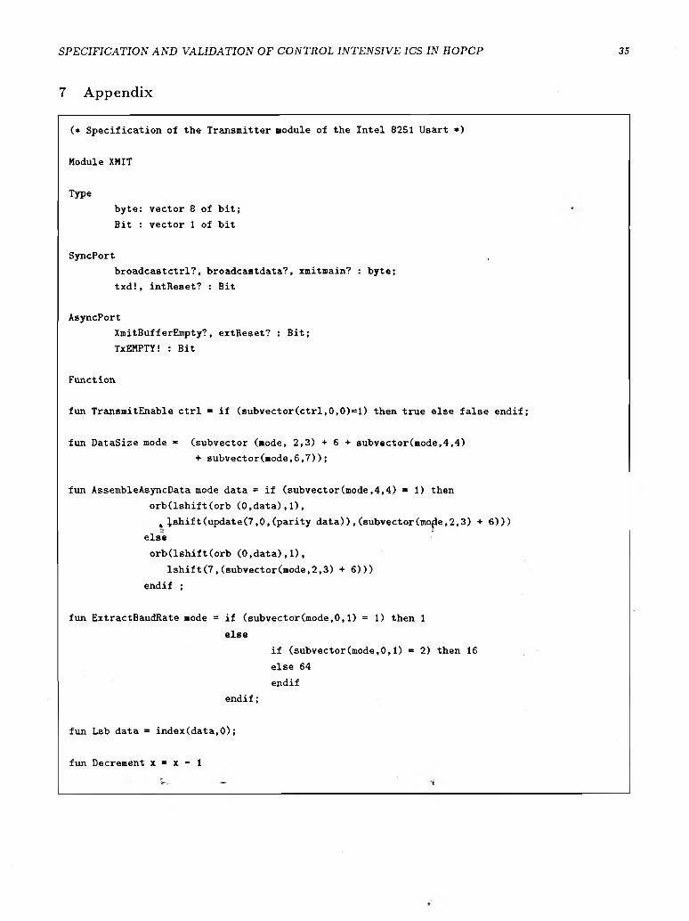
S P E C IF IC A T IO N A N D V A L ID A T IO N O F C O N T R O L IN T E N S IV E ICS IN H O P C P 35
7 A p p en d ix
(* Specification of the Transmitter module of the Intel 8251 Usart *)
Module XMIT
Type
byte: vector 8 of bit;
Bit : vector 1 of bit
SyncPort ,
broadcastctrl?, broadcastdata?, xmitmain? : byte;
txd!, intReset? : Bit
AsyncPort
XmitBufferEmpty?, extReset? : Bit;
TxEMPTY! : Bit
Function
fun TransmitEnable Ctrl = if (subvector(ctrl,0,0)=l) then true else false endif;
fun DataSize mode ■ (subvector (mode, 2,3) + 6 + subvector(mode,4,4)
+ subvector(mode,6,7));
fun AssembleAsyncData mode data = if (subvector(mode,4,4) = 1) then
orb(lshift(orb (0,data),l),
t ^shift(update(7,0,(parity data)),(subvector(mo£e,2,3) + 6)))
else
orb(lshift(orb (0,data),l),
lshift(7,(subvector(mode,2,3) + 6)))
endif ;
fun ExtractBaudRate mode = if (subvector(mode,0,1) = 1) then 1
else
if (subvector(mode,0,1) = 2) then 16
else 64
endif
endif;
fun Lsb data = index(data,0);
fun Decrement x = x - 1
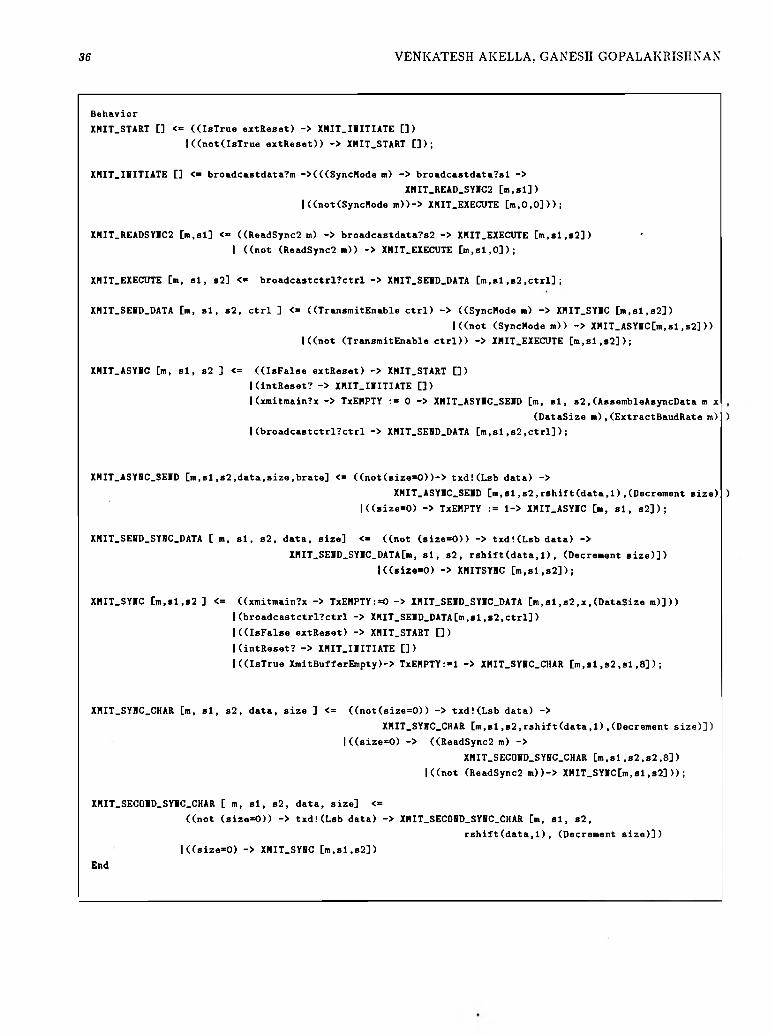
36 VENKATESH AKELLA, GANESH GOPALAKRISHNAN
Behavior
XHIT.START [] <= ((IsTrue extReset) -> XHIT.IIITIATE [])
I((not(IsTrue extReset)) -> XHIT.START []);
XHIT.IIITIATE [] <■ broadcastdata?m ->(((SyncHode n) -> broadcastdata?sl ->
XHIT_READ_SYIC2 [m,sl])
I ((not(SyncHode m))-> XHIT.EXECUTE [in,0,0]));
XHIT.READSYIC2 [m.sl] <= ((ReadSync2 m) -> broadcastdata?s2 -> XHIT.EXECUTE [m,sl,s2]) •
I ((not (ReadSync2 m)) -> XHIT.EXECUTE [m,sl,0]);
XHIT.EXECUTE [m, si, s2] <» broadcastctrlTctrl -> XHIT.SEID.DATA [m,sl,s2,ctrl];
XHIT.SEID.DATA [m, si, s2, Ctrl ] <= ((TransmitEnable Ctrl) -> ((SyncHode in) -> XHIT.SYIC [m,sl,s2])
I((not (SyncHode m)) -> XHIT_ASYHC[m,sl,s2]))
I((not (TransmitEnable Ctrl)) -> XHIT.EXECUTE [m,sl,s2]);
XHIT.ASYIC [m, si, s2 ] <= ((IsFalse extReset) -> XHIT.START [])
I (intReset? -> XHIT.IIITIATE [])
I(xmitmain?x -> TxEHPTY :■ 0 -> XHIT.ASYIC.SEID [m, si, s 2 ,(AssembleAsyncData m x
(DataSize m ) ,(ExtractBaudRate m) )
I(broadcastctrl?ctrl -> XHIT.SEID.DATA [m,sl,s2,ctrl]);
XHIT.ASYIC.SEID [m,si,s2,data,size,brate] <= ((not(size»0))-> t x d !(Lsb data) ->
XHIT.ASYIC.SEID [m.sl,s2,rshift(data,1),(Decrement size)!)
I((size'O) -> TxEHPTY := l-> XHIT.ASYIC [m, si, s2]);
XHIT.SEID.SYIC.DATA [ m, si, s2, data, size] <■ ((not (size=0)) -> txd!(Lsb data) ->
XHIT_SEID.SYIC_DATA[m, si, s 2 , rshift(data,1), (Decrement size)])
l((size=0) -> XHITSYIC [m,sl ,s2]) ;
XHIT.SYIC [m,sl,s2 ] <= ((xmitmain?x -> TxEHPTY:=0 -> XHIT.SEID.SYIC.DATA [m,sl,s2,x,(DataSize m)]))
I(broadcastctrl?ctrl -> XHIT.SEID.DATA[m,si,s2,ctrl])
I((IsFalse extReset) -> XHIT.START [])
I(intReset? -> XHIT.IIITIATE [] )
I ((IsTrue XmitBufferEmpty)-> TxEHPTY:»l -> XHIT.SYIC.CHAR [m.sl,s2,sl ,8]);
XHIT.SYBC.CHAR [m, si, s 2 , data, size ] <= ((not(size=0)) -> txd!(Lsb data) ->
XHIT.SYIC.CHAR [m,si,s2,rshift(data,1),(Decrement size)])
|((size=0) -> ((ReadSync2 m) ->
XHIT.SECOID_SYIC.CHAR [m.sl,s2,s2,8])
I((not (ReadSync2 m))-> XHIT_SYIC[m,sl,s2]));
XHIT.SECOID.SYIC.CHAR [ m, si, s2, data, size] <=
((not (size=0)) -> txd!(Lsb data) -> XHIT.SECOID.SYIC.CHAR [m, si, s 2 ,
rshift(data.l), (Decrement size)])
|((size=0) -> XHIT.SYIC [m,sl,s2])
End
Related Documents