Spacesaver Corporation Manual for Power Pro/EC300/EC400 Series System Diagnostic Unit Revision 3.6

Welcome message from author
This document is posted to help you gain knowledge. Please leave a comment to let me know what you think about it! Share it to your friends and learn new things together.
Transcript
Spacesaver Corporation
Manual for Power Pro/EC300/EC400 Series
System Diagnostic Unit
Revision 3.6
DPU/DO - Page 2 - REV. 5/25/00
Copyright 2000 Spacesaver Corporation. All rights reserved. Reproduction of this document, in part or in whole, by any means, electrical or otherwise, is prohibited, except by written permission from Spacesaver Corporation. The information contained herein is believed to be accurate as of the date of publication; however, Spacesaver Corporation will not be liable for any damages, including indirect or consequential, from the use of this software product or reliance on the accuracy of this documentation. The information contained herein is subject to change without notice.

DPU/DO - Page 3 - REV. 5/25/00
Table of Contents SUBJECT PAGE NUMBER Scope of This Manual 6 Overview and Requirements 7 Installation 9 Power Connection 10 Establishing Communications 11 System Statistics Report 14 Diagnose Board Inputs 15 View/Set Parameters (EC300/400) 23 View/Set Parameters (Power Pro) 44 How to Save Parameters 52 Examine Hex Registers 53 Remote Operation Guide 54 Page Identification Code: DPU - Diagnostic/Programmer Unit DO - Diagnostic Operation Page number Rev. 5/00 - Latest Revision Date
DPU/DO - Page 4 - REV. 5/25/00
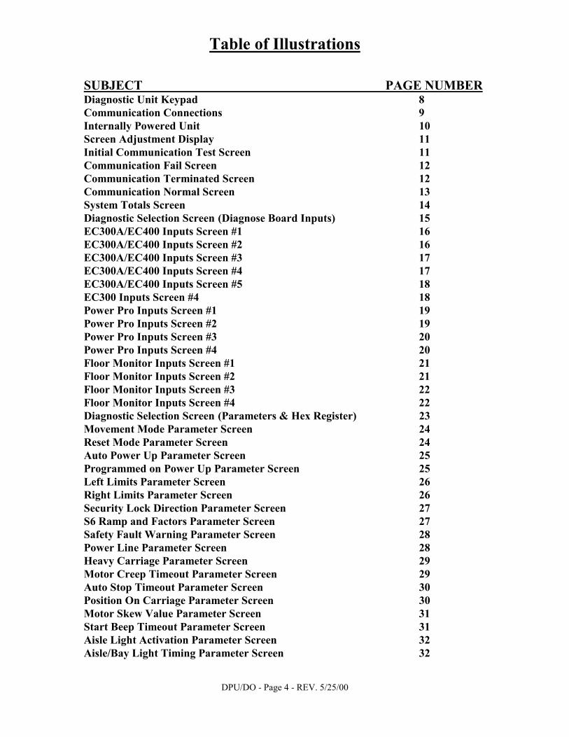
Table of Illustrations SUBJECT PAGE NUMBER Diagnostic Unit Keypad 8 Communication Connections 9 Internally Powered Unit 10 Screen Adjustment Display 11 Initial Communication Test Screen 11 Communication Fail Screen 12 Communication Terminated Screen 12 Communication Normal Screen 13 System Totals Screen 14 Diagnostic Selection Screen (Diagnose Board Inputs) 15 EC300A/EC400 Inputs Screen #1 16 EC300A/EC400 Inputs Screen #2 16 EC300A/EC400 Inputs Screen #3 17 EC300A/EC400 Inputs Screen #4 17 EC300A/EC400 Inputs Screen #5 18 EC300 Inputs Screen #4 18 Power Pro Inputs Screen #1 19 Power Pro Inputs Screen #2 19 Power Pro Inputs Screen #3 20 Power Pro Inputs Screen #4 20 Floor Monitor Inputs Screen #1 21 Floor Monitor Inputs Screen #2 21 Floor Monitor Inputs Screen #3 22 Floor Monitor Inputs Screen #4 22 Diagnostic Selection Screen (Parameters & Hex Register) 23 Movement Mode Parameter Screen 24 Reset Mode Parameter Screen 24 Auto Power Up Parameter Screen 25 Programmed on Power Up Parameter Screen 25 Left Limits Parameter Screen 26 Right Limits Parameter Screen 26 Security Lock Direction Parameter Screen 27 S6 Ramp and Factors Parameter Screen 27 Safety Fault Warning Parameter Screen 28 Power Line Parameter Screen 28 Heavy Carriage Parameter Screen 29 Motor Creep Timeout Parameter Screen 29 Auto Stop Timeout Parameter Screen 30 Position On Carriage Parameter Screen 30 Motor Skew Value Parameter Screen 31 Start Beep Timeout Parameter Screen 31 Aisle Light Activation Parameter Screen 32 Aisle/Bay Light Timing Parameter Screen 32

DPU/DO - Page 5 - REV. 5/25/00
Aisle Light Timeout Parameter Screen 33 Option Output Parameter Screen 33 Bay Light Timeout Parameter Screen 34 Zero Force Sensors Parameter Screen 34 ZFS Left Aisle LEDs Parameter Screen 35 ZFS Right Aisle LEDs Parameter Screen 35 ZFS Background Light Parameter Screen 36 ZFS Reset With Key Parameter Screen 36 ZFS Parameter 5 Screen 37 ZFS Quadrature Usage Parameter Screen 37 ZFS Aisle Usage Parameter Screen 37 Option Register 1 Night Park Parameter Screen 38 Option Register 2 Fire Park Parameter Screen 38 Option Value 2 Time to Park Parameter Screen 39 Option Value 1 Aisle Spacing Parameter Screen 39 Option Value 3 Last Spacing Parameter Screen 40 Option Register 3 Auto Move Parameter Screen 40 Option Value 5 Aisle Number Parameter Screen 41 Option Value 4 Timer Parameter Screen 41 Option Register 4 Infrared Option Screen (EC400) 42 Move From Safety Activation Parameter Screen 43 Option Register 4 Move on Safety Parameter Screen 43 Power Pro Parameter Screens Photo Sweep Type Selection Parameter Screen 44 Left Photo Sweep Enable Parameter Screen 44 Right Photo Sweep Enable Parameter Screen 44 Reset Mode Parameter Screen 45 Relock Aisle Parameter Screen 45 Aisle Relock Timeout Parameter Screen 46 Lighting Control Output Parameter Screen 46 Light Timed Parameter Screen 47 Light Timeout Units Parameter Screen 47 Lighting Timeout Parameter Screen 48 Control Head Beep Disable Parameter Screen 48 Motor Creep Timeout Parameter Screen 49 Auto Stop Timeout Parameter Screen 49 Movement Mode Parameter Screen 50 Left Limits Parameter Screen 50 Right Limits Parameter Screen 51 Power Line Frequency Parameter Screen 51 Examine Hex Registers Screen 53 Remote Startup Screen 54 Communication Failure Screen 54 Remote Ready Screen 55

DPU/DO - Page 6 - REV. 5/25/00
Scope of This Manual This manual covers the operation of Spacesaver Corporation System Diagnostic Unit for the Power Pro, EC300 and EC400 series of Carriage Controls:
Model Power Pro, EC300 and EC400 SYSTEM DIAGNOSTIC
The Diagnostic Unit supports the following functions by control type: Controller Diagnose Remote Control Program Power Pro Yes Yes Yes EC300 Yes Yes - EC300A Yes Yes Yes EC300B Yes Yes Yes EC400 Yes Yes Yes Safety Floor Monitor Yes - -
Any questions or comments about the System Diagnostic Unit product, mobile storage system controls or this manual should be directed to:
Spacesaver Corporation Customer Service
1450 Janesville Avenue Fort Atkinson, Wisconsin 53538-2798
(920) 563-6362
(800) 457-5463 (HLP-LINE) FAX (920) 563-2702

DPU/DO - Page 7 - REV. 5/25/00
Power Pro/EC300/EC400 System Diagnostic Overview and Requirements
The Power Pro/EC300/EC400 System Diagnostic consists of a single unit and interconnecting cable, which connects to any Spacesaver module of mobile storage, fitted with the Power Pro, EC300 or EC400 controls. The System Diagnostic Unit is housed in a black plastic case and comes equipped with system communication cable, wall-mounted transformer power supply and 12 VDC auto adapter1. The Diagnostic Unit provides the following functions: • Automated troubleshooting of Power Pro, EC300 and EC400 system communication. • Diagnostic testing of Power Pro, EC300 and EC400 board functions such as limit switch and
safety sweep inputs. • Setting of system parameters on the Power Pro, EC300A and EC400 series of control boards. • Remote operation of a Power Pro, EC300 or EC400 module of mobile storage. All functions are available on the System Diagnostic Unit without changing setups or operational modes. Requirements for Use • Connection to Spacesaver Power Pro, EC300 or EC400 Series Mobile Storage Controls with
provided communication cable. The Power Pro requires a ten-pin connector adapter. • One 120-Volt Power Supply 2 located within 5 feet of the unit. The unit will operate without
outlet power if fully charged. See page 10 for charging instructions.
1 & 2 As of October 1998, Spacesaver has changed the diagnostic unit to get its power from the logic board eliminating the need for internal batteries, the charger unit and power jack.
DPU/DO - Page 8 - REV. 5/25/00
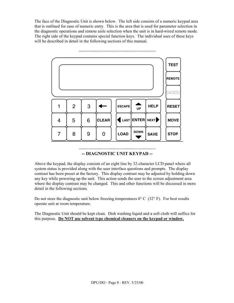
The face of the Diagnostic Unit is shown below. The left side consists of a numeric keypad area that is outlined for ease of numeric entry. This is the area that is used for parameter selection in the diagnostic operations and remote aisle selection when the unit is in hard-wired remote mode. The right side of the keypad contains special function keys. The individual uses of these keys will be described in detail in the following sections of this manual.
--------------------------------------------------------------
TEST
REMOTE
STOP
MOVE
RESET1 2 3
4 5 6
7 8 9 0
CLEAR
LOAD SAVE
HELP
ENTER
ESCAPE
NEXTLAST
UP
DOWN
-------------------------------------------------------------- -- DIAGNOSTIC UNIT KEYPAD --
Above the keypad, the display consists of an eight line by 32-character LCD panel where all system status is provided along with the user interface questions and prompts. The display contrast has been preset at the factory. This display contrast may be adjusted by holding down any key while powering up the unit. This action sends the user to the screen adjustment area where the display contrast may be changed. This and other functions will be discussed in more detail in the following sections. Do not store the diagnostic unit below freezing temperatures 0° C (32° F). For best results operate unit at room temperature. The Diagnostic Unit should be kept clean. Dish washing liquid and a soft cloth will suffice for this purpose. Do NOT use solvent type chemical cleaners on the keypad or window.
DPU/DO - Page 9 - REV. 5/25/00
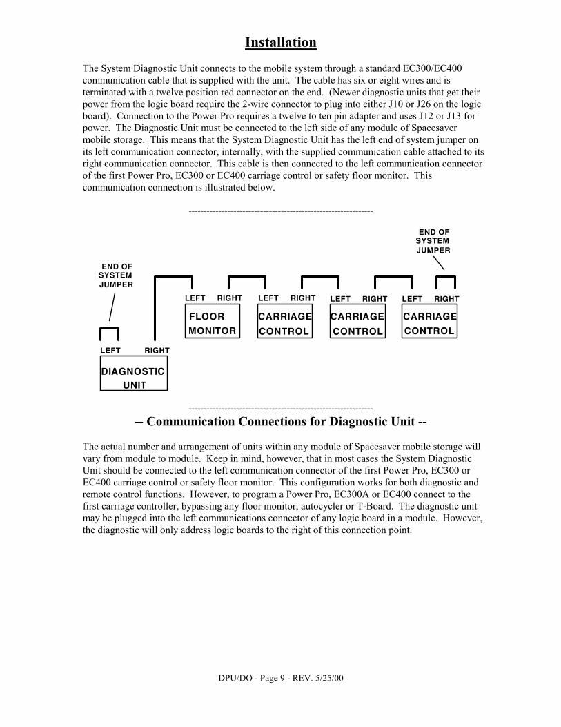
Installation The System Diagnostic Unit connects to the mobile system through a standard EC300/EC400 communication cable that is supplied with the unit. The cable has six or eight wires and is terminated with a twelve position red connector on the end. (Newer diagnostic units that get their power from the logic board require the 2-wire connector to plug into either J10 or J26 on the logic board). Connection to the Power Pro requires a twelve to ten pin adapter and uses J12 or J13 for power. The Diagnostic Unit must be connected to the left side of any module of Spacesaver mobile storage. This means that the System Diagnostic Unit has the left end of system jumper on its left communication connector, internally, with the supplied communication cable attached to its right communication connector. This cable is then connected to the left communication connector of the first Power Pro, EC300 or EC400 carriage control or safety floor monitor. This communication connection is illustrated below.
--------------------------------------------------------------
FLOOR
MONITOR
CARRIAGE
CONTROL
LEFT
LEFT
RIGHT
RIGHT
CARRIAGE
CONTROL
LEFT RIGHT
CARRIAGE
CONTROL
LEFT RIGHT
DIAGNOSTICUNIT
LEFT RIGHT
END OFSYSTEMJUMPER
END OFSYSTEMJUMPER
-------------------------------------------------------------- -- Communication Connections for Diagnostic Unit --
The actual number and arrangement of units within any module of Spacesaver mobile storage will vary from module to module. Keep in mind, however, that in most cases the System Diagnostic Unit should be connected to the left communication connector of the first Power Pro, EC300 or EC400 carriage control or safety floor monitor. This configuration works for both diagnostic and remote control functions. However, to program a Power Pro, EC300A or EC400 connect to the first carriage controller, bypassing any floor monitor, autocycler or T-Board. The diagnostic unit may be plugged into the left communications connector of any logic board in a module. However, the diagnostic will only address logic boards to the right of this connection point.

DPU/DO - Page 10 - REV. 5/25/00
Power Connection A.) INTERNALLY POWERED: The System Diagnostic Unit can be run on internal battery power. The battery is charged by a UL Listed 120VAC to 12VDC wall-mount transformer which must be connected to a 120 VAC outlet. The output of the transformer is class 2, 12 VDC at 800 ma. The cord from the transformer plugs into a special power connector on the front of the unit. The battery will reach a full charge after twelve hours of charging time, which gives up to eight hours of continuous battery-powered operation. The unit need not be turned on during battery charging. The unit comes equipped with an automobile cigarette lighter adapter. This allows the unit to be charged while in transit. The unit may also be run directly with the power transformer plugged into a wall outlet. The unit will need to be charged when the display begins to fade or go blank. Another indication the unit needs to be recharged is when the diagnostic creates a bad left sweep on the controller to which it is connected. The illustration below shows the System Diagnostic Unit and its cables and connections. B.) EXTERNALLY POWERED: As of October 1998, Spacesaver has changed the diagnostic unit to get its power from the logic board eliminating the need for internal batteries, the charger unit and power jack. The logic board provides power to the unit from either J10 or J26 (J12 or J13 for Power Pro entry sensor transmitters) via a separate connector. In most cases the logic board will have sufficient power. If excess power draw is encountered, extra options (entry sensors etc.) may be unplugged and temporarily jumped out during diagnostic use only. Be sure to restore jumped out options and test when finished.
--------------------------------------------------------------
Spacesaver
SWITCHPOWER
120VAC12VDC
POWERTRANSFORMER
COMMUNICATIONCABLE
CABLESTORAGE
TRANSFORMERSTORAGE
AUTO ADAPTORSTORAGE
-------------------------------------------------------------- -- Internally Powered Unit--

DPU/DO - Page 11 - REV. 5/25/00
Establishing Communications After communication connections and power connections (if needed) have been made, turning the System Diagnostic Unit on will cause it to perform an internal self-test, the internal beeper will sound and one of two startup screens will be displayed. If the user holds down any key on the keypad while the unit is being powered on, the screen adjustment display will appear. This screen is shown below.
-------------------------------- SPACESAVER DIAGNOSTIC UNIT 3.6 SCREEN ADJUSTMENT Press a Key: <UP> Brighter <DOWN> Dimmer <ESCAPE> to Exit --------------------------------
-- SCREEN ADJUSTMENT DISPLAY -- While this screen is being displayed, the intensity of the LCD screen can be adjusted. Pressing the UP key on the keypad will increase the intensity of the display, while pressing the DOWN key will decrease the intensity. The intensity is variable from very dim to a blacked-out screen. When the user is satisfied with the displayed intensity, pressing the ESCAPE key will exit the user to the initial communication test screen. When the user powers up the System Diagnostic Unit without holding down a key, or presses the ESCAPE key when exiting the screen adjustment area, the initial communication test screen is displayed. This screen, which is shown below, informs the user that Power Pro/EC300/EC400 communication in the module is being tested for completeness and proper termination.
-------------------------------- SPACESAVER DIAGNOSTIC UNIT 3.6 TESTING COMMUNICATION one moment please... --------------------------------
-- Initial Communication Test Screen -- Upon completion of the initial communication test, one of three screens will be displayed. The first of these is the communication fail screen that is shown at the top of the next page.
DPU/DO - Page 12 - REV. 5/25/00
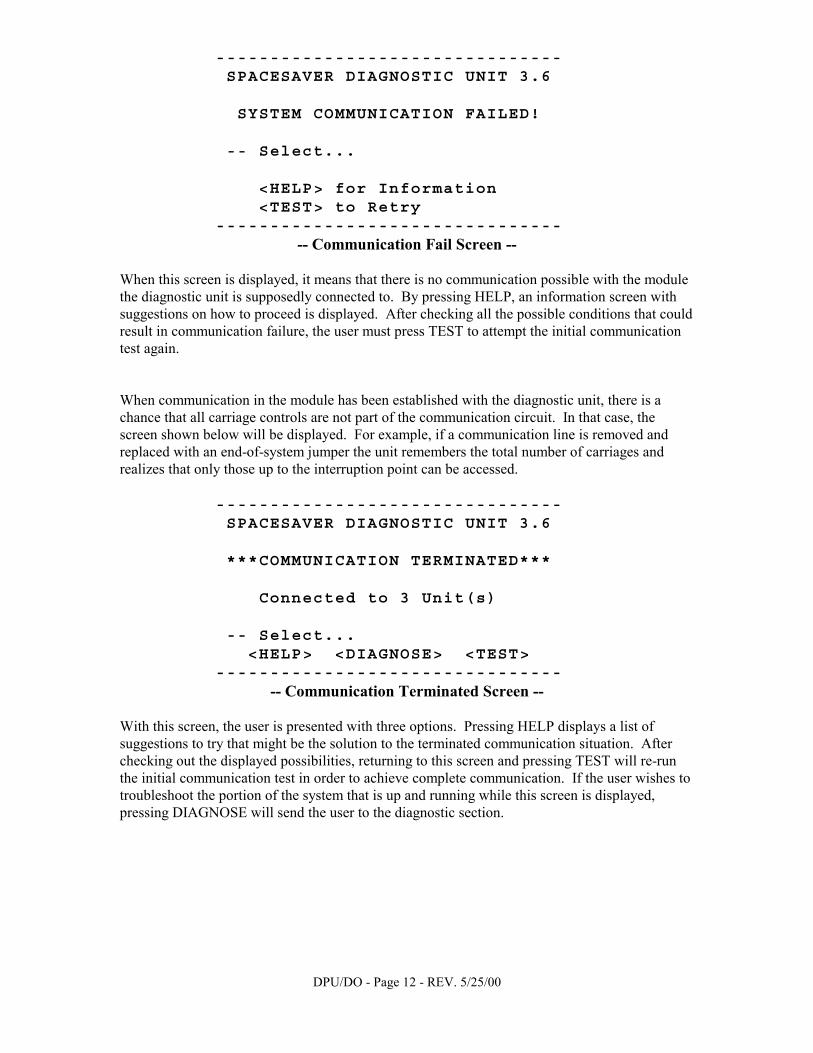
-------------------------------- SPACESAVER DIAGNOSTIC UNIT 3.6 SYSTEM COMMUNICATION FAILED! -- Select... <HELP> for Information <TEST> to Retry --------------------------------
-- Communication Fail Screen -- When this screen is displayed, it means that there is no communication possible with the module the diagnostic unit is supposedly connected to. By pressing HELP, an information screen with suggestions on how to proceed is displayed. After checking all the possible conditions that could result in communication failure, the user must press TEST to attempt the initial communication test again. When communication in the module has been established with the diagnostic unit, there is a chance that all carriage controls are not part of the communication circuit. In that case, the screen shown below will be displayed. For example, if a communication line is removed and replaced with an end-of-system jumper the unit remembers the total number of carriages and realizes that only those up to the interruption point can be accessed.
-------------------------------- SPACESAVER DIAGNOSTIC UNIT 3.6 ***COMMUNICATION TERMINATED*** Connected to 3 Unit(s) -- Select... <HELP> <DIAGNOSE> <TEST> --------------------------------
-- Communication Terminated Screen --
With this screen, the user is presented with three options. Pressing HELP displays a list of suggestions to try that might be the solution to the terminated communication situation. After checking out the displayed possibilities, returning to this screen and pressing TEST will re-run the initial communication test in order to achieve complete communication. If the user wishes to troubleshoot the portion of the system that is up and running while this screen is displayed, pressing DIAGNOSE will send the user to the diagnostic section.
DPU/DO - Page 13 - REV. 5/25/00
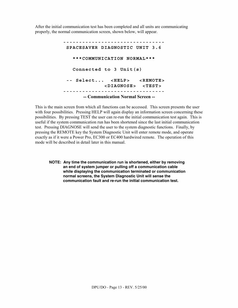
After the initial communication test has been completed and all units are communicating properly, the normal communication screen, shown below, will appear.
-------------------------------- SPACESAVER DIAGNOSTIC UNIT 3.6 ***COMMUNICATION NORMAL*** Connected to 3 Unit(s) -- Select... <HELP> <REMOTE> <DIAGNOSE> <TEST> --------------------------------
-- Communication Normal Screen -- This is the main screen from which all functions can be accessed. This screen presents the user with four possibilities. Pressing HELP will again display an information screen concerning these possibilities. By pressing TEST the user can re-run the initial communication test again. This is useful if the system communication run has been shortened since the last initial communication test. Pressing DIAGNOSE will send the user to the system diagnostic functions. Finally, by pressing the REMOTE key the System Diagnostic Unit will enter remote mode, and operate exactly as if it were a Power Pro, EC300 or EC400 hardwired remote. The operation of this mode will be described in detail later in this manual.
NOTE: Any time the communication run is shortened, either by removing an end of system jumper or pulling off a communication cable while displaying the communication terminated or communication normal screens, the System Diagnostic Unit will sense the communication fault and re-run the initial communication test.

DPU/DO - Page 14 - REV. 5/25/00
System Statistics Report
Pressing the DIAGNOSE key from either the Communication Terminated or Communication Normal screen sends the user to the System Statistics collection function of the System Diagnostic Unit. The unit polls the entire system to find out what kind and quantity of controls that are in the module. It also checks the revision number of the software in all the moveable units. If there is a difference in revision levels, the message "Revision Mismatch in Module!!!" is displayed at the bottom of the screen. Those findings are displayed on the screen shown below.
-------------------------------- SPACESAVER DIAGNOSTIC UNIT 3.6 -- Total Controller Units -- 3 Moveable Units --------- 2 Safety Floor Monitors -- 1 -- Select... <HELP> <DIAGNOSE> <ESCAPE> --------------------------------
-- System Totals Screen -- If the message "Revision Mismatch in Module!!!" is displayed on this screen one or more moveable units have a different version of software. Usually, for proper operation, the entire module needs to be the same. See page 16 for an easy technique to determine which unit has the different revision software. Pressing the HELP key from this screen informs the user about the information shown here and what it means. This screen allows the user to press DIAGNOSE in order to continue on with the diagnostic functions. Pressing ESCAPE sends the user back to the previous screen, either the communication normal or communication terminated screen.
NOTE: If communication is broken while this screen is displayed, either by removing an end of system jumper or pulling off a communications cable, any attempt to leave this screen will alert the System Diagnostic Unit, which will re-run the initial communication test.
While the system totals are being displayed, pressing the DIAGNOSE key brings up the Diagnostic Selection screen shown on the next page.
DPU/DO - Page 15 - REV. 5/25/00
Diagnose Board Inputs
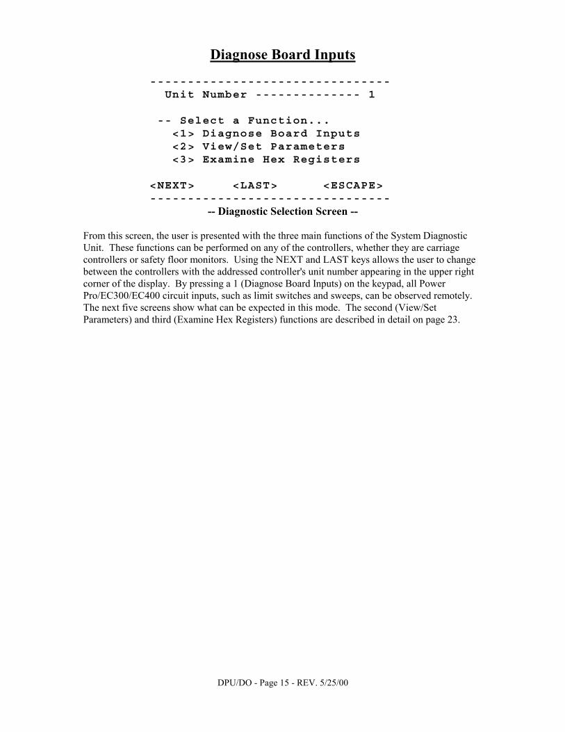
-------------------------------- Unit Number -------------- 1 -- Select a Function... <1> Diagnose Board Inputs <2> View/Set Parameters <3> Examine Hex Registers <NEXT> <LAST> <ESCAPE> --------------------------------
-- Diagnostic Selection Screen -- From this screen, the user is presented with the three main functions of the System Diagnostic Unit. These functions can be performed on any of the controllers, whether they are carriage controllers or safety floor monitors. Using the NEXT and LAST keys allows the user to change between the controllers with the addressed controller's unit number appearing in the upper right corner of the display. By pressing a 1 (Diagnose Board Inputs) on the keypad, all Power Pro/EC300/EC400 circuit inputs, such as limit switches and sweeps, can be observed remotely. The next five screens show what can be expected in this mode. The second (View/Set Parameters) and third (Examine Hex Registers) functions are described in detail on page 23.
DPU/DO - Page 16 - REV. 5/25/00
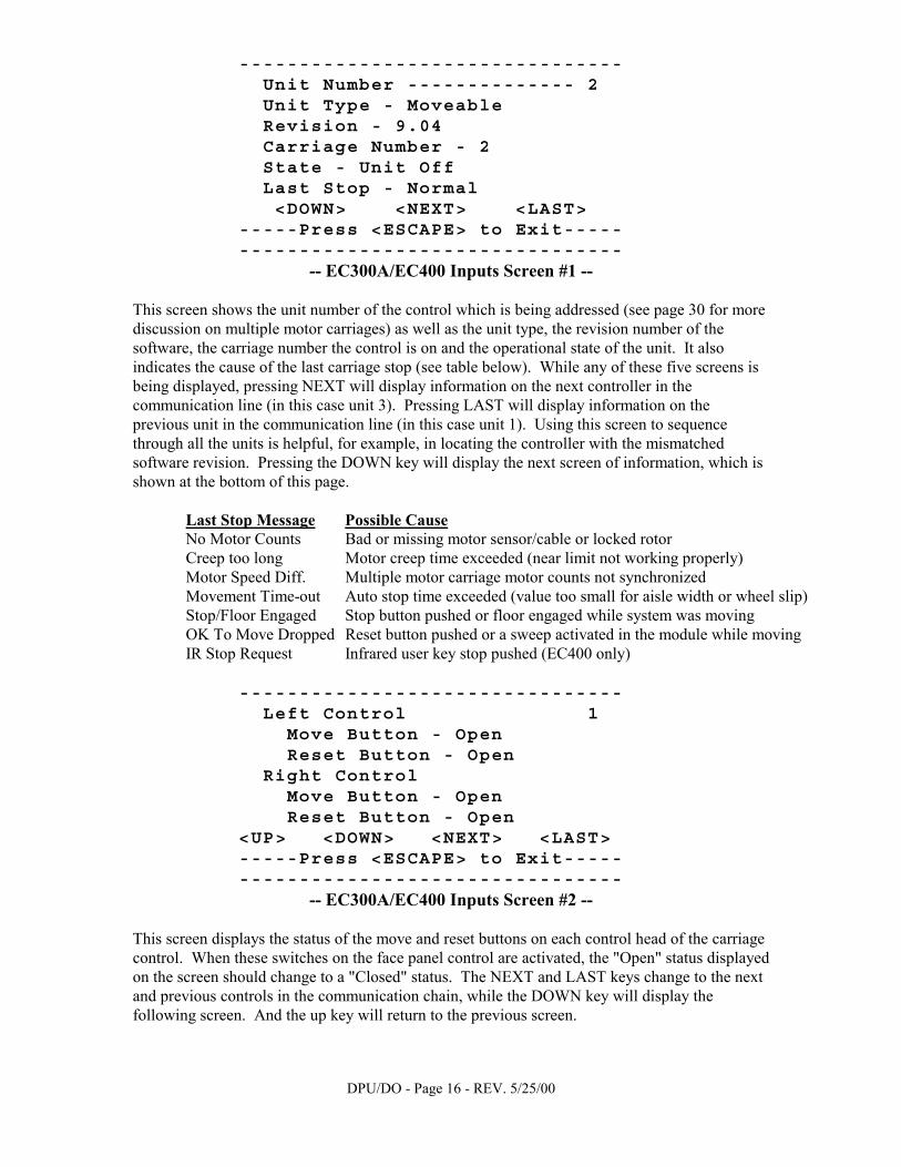
-------------------------------- Unit Number -------------- 2 Unit Type - Moveable Revision - 9.04 Carriage Number - 2 State - Unit Off Last Stop - Normal <DOWN> <NEXT> <LAST> -----Press <ESCAPE> to Exit----- --------------------------------
-- EC300A/EC400 Inputs Screen #1 -- This screen shows the unit number of the control which is being addressed (see page 30 for more discussion on multiple motor carriages) as well as the unit type, the revision number of the software, the carriage number the control is on and the operational state of the unit. It also indicates the cause of the last carriage stop (see table below). While any of these five screens is being displayed, pressing NEXT will display information on the next controller in the communication line (in this case unit 3). Pressing LAST will display information on the previous unit in the communication line (in this case unit 1). Using this screen to sequence through all the units is helpful, for example, in locating the controller with the mismatched software revision. Pressing the DOWN key will display the next screen of information, which is shown at the bottom of this page.
Last Stop Message Possible Cause No Motor Counts Bad or missing motor sensor/cable or locked rotor Creep too long Motor creep time exceeded (near limit not working properly) Motor Speed Diff. Multiple motor carriage motor counts not synchronized Movement Time-out Auto stop time exceeded (value too small for aisle width or wheel slip) Stop/Floor Engaged Stop button pushed or floor engaged while system was moving OK To Move Dropped Reset button pushed or a sweep activated in the module while moving IR Stop Request Infrared user key stop pushed (EC400 only)
-------------------------------- Left Control 1 Move Button - Open Reset Button - Open Right Control Move Button - Open Reset Button - Open <UP> <DOWN> <NEXT> <LAST> -----Press <ESCAPE> to Exit----- --------------------------------
-- EC300A/EC400 Inputs Screen #2 -- This screen displays the status of the move and reset buttons on each control head of the carriage control. When these switches on the face panel control are activated, the "Open" status displayed on the screen should change to a "Closed" status. The NEXT and LAST keys change to the next and previous controls in the communication chain, while the DOWN key will display the following screen. And the up key will return to the previous screen.
DPU/DO - Page 17 - REV. 5/25/00
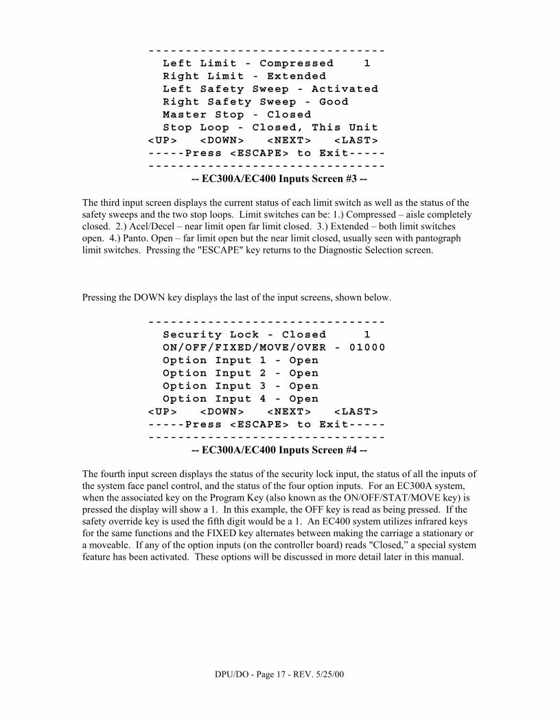
-------------------------------- Left Limit - Compressed 1 Right Limit - Extended Left Safety Sweep - Activated Right Safety Sweep - Good Master Stop - Closed Stop Loop - Closed, This Unit <UP> <DOWN> <NEXT> <LAST> -----Press <ESCAPE> to Exit----- --------------------------------
-- EC300A/EC400 Inputs Screen #3 -- The third input screen displays the current status of each limit switch as well as the status of the safety sweeps and the two stop loops. Limit switches can be: 1.) Compressed – aisle completely closed. 2.) Acel/Decel – near limit open far limit closed. 3.) Extended – both limit switches open. 4.) Panto. Open – far limit open but the near limit closed, usually seen with pantograph limit switches. Pressing the "ESCAPE" key returns to the Diagnostic Selection screen. Pressing the DOWN key displays the last of the input screens, shown below.
-------------------------------- Security Lock - Closed 1 ON/OFF/FIXED/MOVE/OVER - 01000 Option Input 1 - Open Option Input 2 - Open Option Input 3 - Open Option Input 4 - Open <UP> <DOWN> <NEXT> <LAST> -----Press <ESCAPE> to Exit----- --------------------------------
-- EC300A/EC400 Inputs Screen #4 -- The fourth input screen displays the status of the security lock input, the status of all the inputs of the system face panel control, and the status of the four option inputs. For an EC300A system, when the associated key on the Program Key (also known as the ON/OFF/STAT/MOVE key) is pressed the display will show a 1. In this example, the OFF key is read as being pressed. If the safety override key is used the fifth digit would be a 1. An EC400 system utilizes infrared keys for the same functions and the FIXED key alternates between making the carriage a stationary or a moveable. If any of the option inputs (on the controller board) reads "Closed,” a special system feature has been activated. These options will be discussed in more detail later in this manual.
DPU/DO - Page 18 - REV. 5/25/00
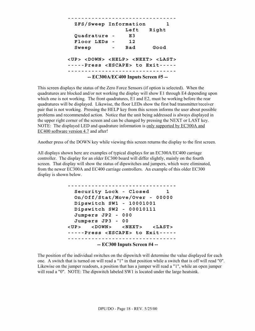
-------------------------------- ZFS/Sweep Information 1 Left Right Quadrature - E3 Floor LEDs - 12 Sweep - Bad Good <UP> <DOWN> <HELP> <NEXT> <LAST> -----Press <ESCAPE> to Exit----- --------------------------------
-- EC300A/EC400 Inputs Screen #5 -- This screen displays the status of the Zero Force Sensors (if option is selected). When the quadratures are blocked and/or not working the display will show E1 through E4 depending upon which one is not working. The front quadratures, E1 and E2, must be working before the rear quadratures will be displayed. Likewise, the floor LEDs show the first bad transmitter/receiver pair that is not working. Pressing the HELP key from this screen informs the user about possible problems and recommended action. Notice that the unit being addressed is always displayed in the upper right corner of the screen and can be changed by pressing the NEXT or LAST key. NOTE: The displayed LED and quadrature information is only supported by EC300A and EC400 software version 4.7 and after! Another press of the DOWN key while viewing this screen returns the display to the first screen. All displays shown here are examples of typical displays for an EC300A/EC400 carriage controller. The display for an older EC300 board will differ slightly, mainly on the fourth screen. That display will show the status of dipswitches and jumpers, which were eliminated, from the newer EC300A and EC400 carriage controllers. An example of this older EC300 display is shown below.
-------------------------------- Security Lock - Closed 1 On/Off/Stat/Move/Over - 00000 Dipswitch SW1 - 10001001 Dipswitch SW2 - 00010111 Jumpers JP2 - 000 Jumpers JP3 - 00 <UP> <DOWN> <NEXT> <LAST> -----Press <ESCAPE> to Exit----- --------------------------------
-- EC300 Inputs Screen #4 -- The position of the individual switches on the dipswitch will determine the value displayed for each one. A switch that is turned on will read a "1" in that position while a switch that is off will read "0". Likewise on the jumper readouts, a position that has a jumper will read a "1", while an open jumper will read a "0". NOTE: The dipswitch labeled SW1 is located under the large heatsink.
DPU/DO - Page 19 - REV. 5/25/00
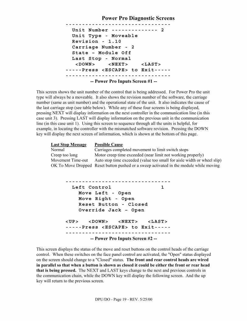
Power Pro Diagnostic Screens -------------------------------- Unit Number -------------- 2 Unit Type - Moveable Revision - 1.10 Carriage Number - 2 State – Module Off Last Stop - Normal <DOWN> <NEXT> <LAST> -----Press <ESCAPE> to Exit----- --------------------------------
-- Power Pro Inputs Screen #1 -- This screen shows the unit number of the control that is being addressed. For Power Pro the unit type will always be a moveable. It also shows the revision number of the software, the carriage number (same as unit number) and the operational state of the unit. It also indicates the cause of the last carriage stop (see table below). While any of these four screens is being displayed, pressing NEXT will display information on the next controller in the communication line (in this case unit 3). Pressing LAST will display information on the previous unit in the communication line (in this case unit 1). Using this screen to sequence through all the units is helpful, for example, in locating the controller with the mismatched software revision. Pressing the DOWN key will display the next screen of information, which is shown at the bottom of this page.
Last Stop Message Possible Cause Normal Carriages completed movement to limit switch stops Creep too long Motor creep time exceeded (near limit not working properly) Movement Time-out Auto stop time exceeded (value too small for aisle width or wheel slip) OK To Move Dropped Reset button pushed or a sweep activated in the module while moving
-------------------------------- Left Control 1 Move Left - Open Move Right - Open Reset Button - Closed Override Jack – Open <UP> <DOWN> <NEXT> <LAST> -----Press <ESCAPE> to Exit----- --------------------------------
-- Power Pro Inputs Screen #2 -- This screen displays the status of the move and reset buttons on the control heads of the carriage control. When these switches on the face panel control are activated, the "Open" status displayed on the screen should change to a "Closed" status. The front and rear control heads are wired in parallel so that when a button is shown as closed it could be either the front or rear head that is being pressed. The NEXT and LAST keys change to the next and previous controls in the communication chain, while the DOWN key will display the following screen. And the up key will return to the previous screen.
DPU/DO - Page 20 - REV. 5/25/00
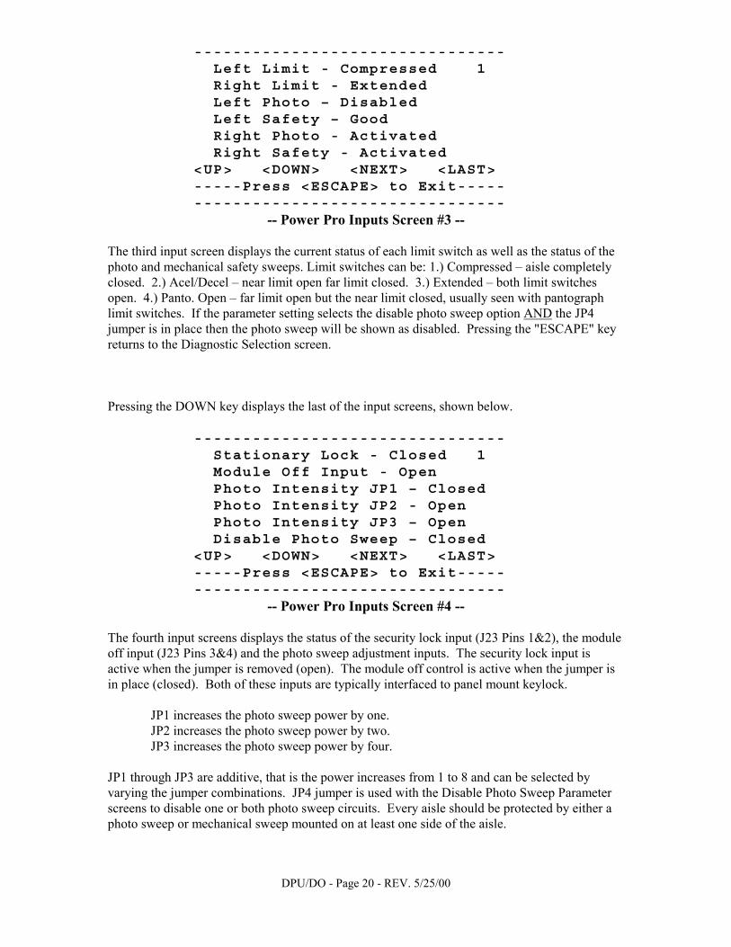
-------------------------------- Left Limit - Compressed 1 Right Limit - Extended Left Photo – Disabled Left Safety – Good Right Photo - Activated Right Safety - Activated <UP> <DOWN> <NEXT> <LAST> -----Press <ESCAPE> to Exit----- --------------------------------
-- Power Pro Inputs Screen #3 -- The third input screen displays the current status of each limit switch as well as the status of the photo and mechanical safety sweeps. Limit switches can be: 1.) Compressed – aisle completely closed. 2.) Acel/Decel – near limit open far limit closed. 3.) Extended – both limit switches open. 4.) Panto. Open – far limit open but the near limit closed, usually seen with pantograph limit switches. If the parameter setting selects the disable photo sweep option AND the JP4 jumper is in place then the photo sweep will be shown as disabled. Pressing the "ESCAPE" key returns to the Diagnostic Selection screen. Pressing the DOWN key displays the last of the input screens, shown below.
-------------------------------- Stationary Lock - Closed 1 Module Off Input - Open Photo Intensity JP1 – Closed Photo Intensity JP2 - Open Photo Intensity JP3 – Open Disable Photo Sweep – Closed <UP> <DOWN> <NEXT> <LAST> -----Press <ESCAPE> to Exit----- --------------------------------
-- Power Pro Inputs Screen #4 -- The fourth input screens displays the status of the security lock input (J23 Pins 1&2), the module off input (J23 Pins 3&4) and the photo sweep adjustment inputs. The security lock input is active when the jumper is removed (open). The module off control is active when the jumper is in place (closed). Both of these inputs are typically interfaced to panel mount keylock.
JP1 increases the photo sweep power by one. JP2 increases the photo sweep power by two. JP3 increases the photo sweep power by four.
JP1 through JP3 are additive, that is the power increases from 1 to 8 and can be selected by varying the jumper combinations. JP4 jumper is used with the Disable Photo Sweep Parameter screens to disable one or both photo sweep circuits. Every aisle should be protected by either a photo sweep or mechanical sweep mounted on at least one side of the aisle.
DPU/DO - Page 21 - REV. 5/25/00
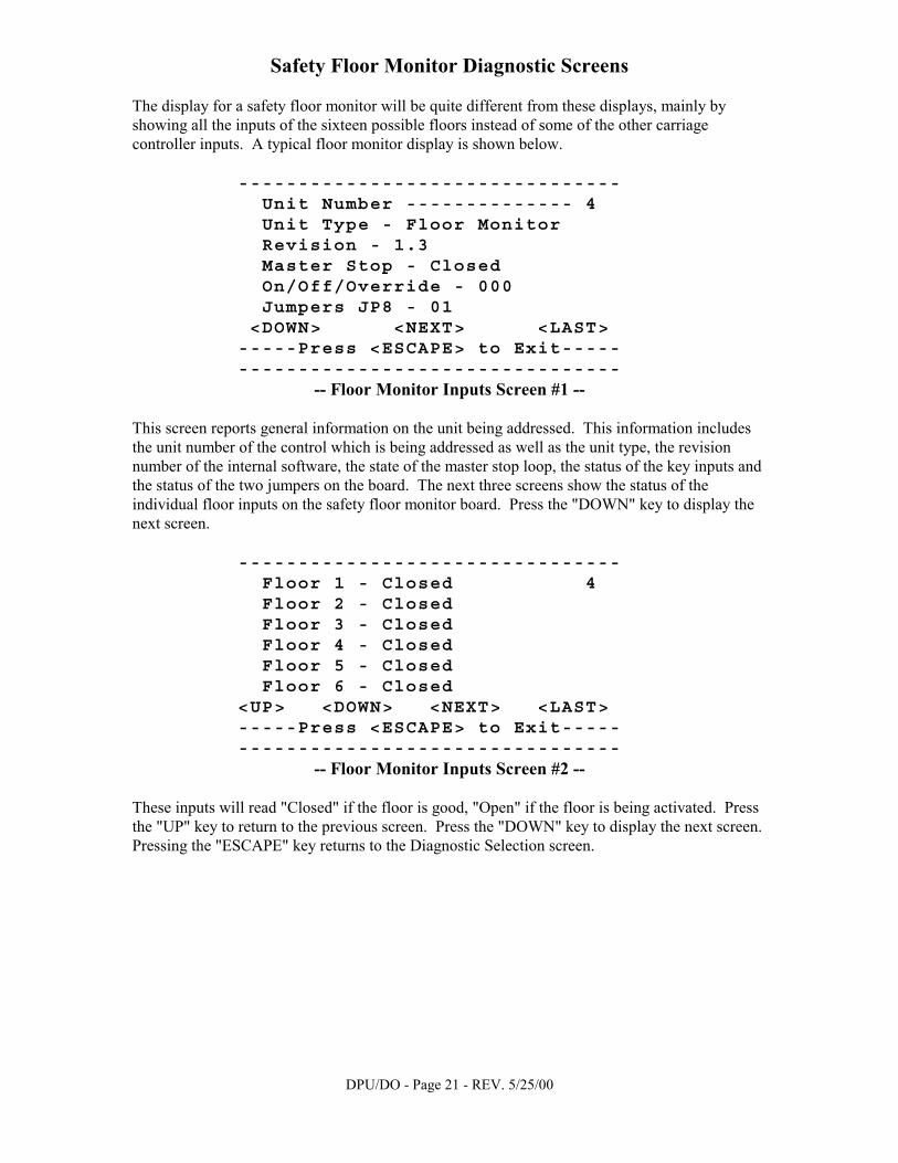
Safety Floor Monitor Diagnostic Screens The display for a safety floor monitor will be quite different from these displays, mainly by showing all the inputs of the sixteen possible floors instead of some of the other carriage controller inputs. A typical floor monitor display is shown below.
-------------------------------- Unit Number -------------- 4 Unit Type - Floor Monitor Revision - 1.3 Master Stop - Closed On/Off/Override - 000 Jumpers JP8 - 01 <DOWN> <NEXT> <LAST> -----Press <ESCAPE> to Exit----- --------------------------------
-- Floor Monitor Inputs Screen #1 -- This screen reports general information on the unit being addressed. This information includes the unit number of the control which is being addressed as well as the unit type, the revision number of the internal software, the state of the master stop loop, the status of the key inputs and the status of the two jumpers on the board. The next three screens show the status of the individual floor inputs on the safety floor monitor board. Press the "DOWN" key to display the next screen.
-------------------------------- Floor 1 - Closed 4 Floor 2 - Closed Floor 3 - Closed Floor 4 - Closed Floor 5 - Closed Floor 6 - Closed <UP> <DOWN> <NEXT> <LAST> -----Press <ESCAPE> to Exit----- --------------------------------
-- Floor Monitor Inputs Screen #2 -- These inputs will read "Closed" if the floor is good, "Open" if the floor is being activated. Press the "UP" key to return to the previous screen. Press the "DOWN" key to display the next screen. Pressing the "ESCAPE" key returns to the Diagnostic Selection screen.
DPU/DO - Page 22 - REV. 5/25/00
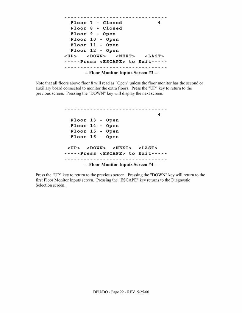
-------------------------------- Floor 7 - Closed 4 Floor 8 - Closed Floor 9 - Open Floor 10 - Open Floor 11 - Open Floor 12 - Open <UP> <DOWN> <NEXT> <LAST> -----Press <ESCAPE> to Exit----- --------------------------------
-- Floor Monitor Inputs Screen #3 -- Note that all floors above floor 8 will read as "Open" unless the floor monitor has the second or auxiliary board connected to monitor the extra floors. Press the "UP" key to return to the previous screen. Pressing the "DOWN" key will display the next screen.
-------------------------------- 4 Floor 13 - Open Floor 14 - Open Floor 15 - Open Floor 16 - Open <UP> <DOWN> <NEXT> <LAST> -----Press <ESCAPE> to Exit----- --------------------------------
-- Floor Monitor Inputs Screen #4 -- Press the "UP" key to return to the previous screen. Pressing the "DOWN" key will return to the first Floor Monitor Inputs screen. Pressing the "ESCAPE" key returns to the Diagnostic Selection screen.

DPU/DO - Page 23 - REV. 5/25/00
View/Set Parameters Notice that the number of the unit being addressed is displayed in the upper right corner of this screen. Use “NEXT” and “LAST” to change the unit number. If the unit being addressed is a carriage controller of the Power Pro/EC300A/EC400 style, the user is presented with the screen below. However, when a safety floor monitor or older EC300 control is being addressed, function 2, the View/Set Parameters line will not be shown. If the unit is a safety floor monitor it does not support or need programming. If the unit is an older EC300 carriage controller it uses dipswitches for setting its parameters.
-------------------------------- Unit Number -------------- 1 -- Select a Function... <1> Diagnose Board Inputs <2> View/Set Parameters <3> Examine Hex Registers <NEXT> <LAST> <ESCAPE> --------------------------------
-- Diagnostic Selection Screen -- Pressing the 3 key from this screen sends the user to a technical area described in detail on page 53. Pressing the 2 key on the keypad from the Diagnostic Selection Screen enters the View/Set Parameters section. To select the various options press the arrow keys corresponding to the NEXT and LAST keys. While in the View/Set Parameters section the unit addressed can not be changed. Return to the diagnostic Selection screen by pushing the ESCAPE key and then select another unit address by using the NEXT or LAST keys. Also, while in the View/Set Parameters section, pressing the HELP key will display the Zero Force Sensors screen. There are two different types of parameter screens to change the options. • One group of parameters is set by multiple choice. These screens all have two or more choices with
numbers to select each one. An asterisk will be displayed to the left of the option currently selected. Choosing a different NUMBER on the keypad will select that option and move the asterisk.
• The other group of parameters requires the user to enter a numerical value. All keys function the same
except for the way the value is entered. On this type of screen the current value is shown on the input line. To change the value, press the CLEAR key to erase the entire value and type in a new one, or backspace over part of the value and type in the new portion. Either way, the user must press the ENTER key to make the new value permanent. The input line also gives the range of values allowable for this particular option. An entry that falls outside the displayed boundaries will be erased when the ENTER key is pressed and the old value will be re-displayed as the current value.
Upon completion of programming for each controller a press of the "SAVE" key is required. Once the information is stored and saved other controllers may be addressed.
Screens in this section with a check mark indicate parameters that need only be programmed into one controller; that can generate commands causing the rest to “follow the leader” (i.e. fire park).
DPU/DO - Page 24 - REV. 5/25/00
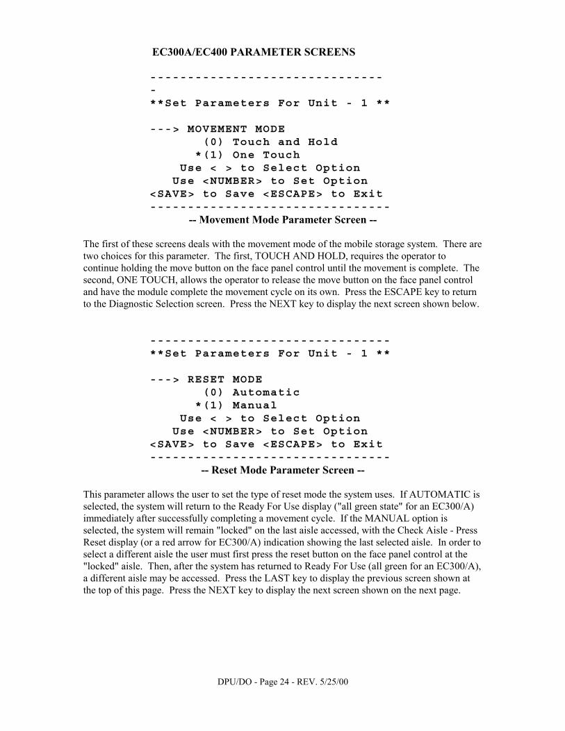
EC300A/EC400 PARAMETER SCREENS
-------------------------------- **Set Parameters For Unit - 1 ** ---> MOVEMENT MODE (0) Touch and Hold *(1) One Touch Use < > to Select Option Use <NUMBER> to Set Option <SAVE> to Save <ESCAPE> to Exit --------------------------------
-- Movement Mode Parameter Screen -- The first of these screens deals with the movement mode of the mobile storage system. There are two choices for this parameter. The first, TOUCH AND HOLD, requires the operator to continue holding the move button on the face panel control until the movement is complete. The second, ONE TOUCH, allows the operator to release the move button on the face panel control and have the module complete the movement cycle on its own. Press the ESCAPE key to return to the Diagnostic Selection screen. Press the NEXT key to display the next screen shown below.
-------------------------------- **Set Parameters For Unit - 1 ** ---> RESET MODE (0) Automatic *(1) Manual Use < > to Select Option Use <NUMBER> to Set Option <SAVE> to Save <ESCAPE> to Exit --------------------------------
-- Reset Mode Parameter Screen -- This parameter allows the user to set the type of reset mode the system uses. If AUTOMATIC is selected, the system will return to the Ready For Use display ("all green state" for an EC300/A) immediately after successfully completing a movement cycle. If the MANUAL option is selected, the system will remain "locked" on the last aisle accessed, with the Check Aisle - Press Reset display (or a red arrow for EC300/A) indication showing the last selected aisle. In order to select a different aisle the user must first press the reset button on the face panel control at the "locked" aisle. Then, after the system has returned to Ready For Use (all green for an EC300/A), a different aisle may be accessed. Press the LAST key to display the previous screen shown at the top of this page. Press the NEXT key to display the next screen shown on the next page.
DPU/DO - Page 25 - REV. 5/25/00
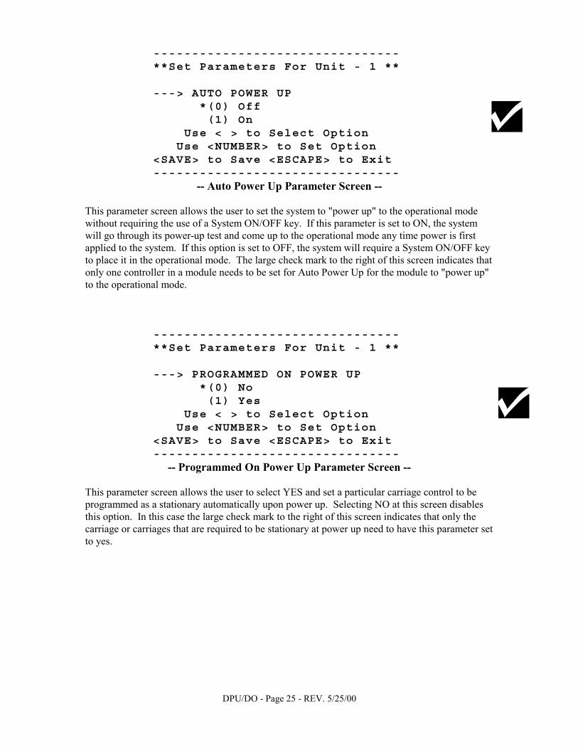
-------------------------------- **Set Parameters For Unit - 1 ** ---> AUTO POWER UP *(0) Off (1) On Use < > to Select Option Use <NUMBER> to Set Option <SAVE> to Save <ESCAPE> to Exit --------------------------------
-- Auto Power Up Parameter Screen -- This parameter screen allows the user to set the system to "power up" to the operational mode without requiring the use of a System ON/OFF key. If this parameter is set to ON, the system will go through its power-up test and come up to the operational mode any time power is first applied to the system. If this option is set to OFF, the system will require a System ON/OFF key to place it in the operational mode. The large check mark to the right of this screen indicates that only one controller in a module needs to be set for Auto Power Up for the module to "power up" to the operational mode.
-------------------------------- **Set Parameters For Unit - 1 ** ---> PROGRAMMED ON POWER UP *(0) No (1) Yes Use < > to Select Option Use <NUMBER> to Set Option <SAVE> to Save <ESCAPE> to Exit --------------------------------
-- Programmed On Power Up Parameter Screen -- This parameter screen allows the user to select YES and set a particular carriage control to be programmed as a stationary automatically upon power up. Selecting NO at this screen disables this option. In this case the large check mark to the right of this screen indicates that only the carriage or carriages that are required to be stationary at power up need to have this parameter set to yes.
DPU/DO - Page 26 - REV. 5/25/00
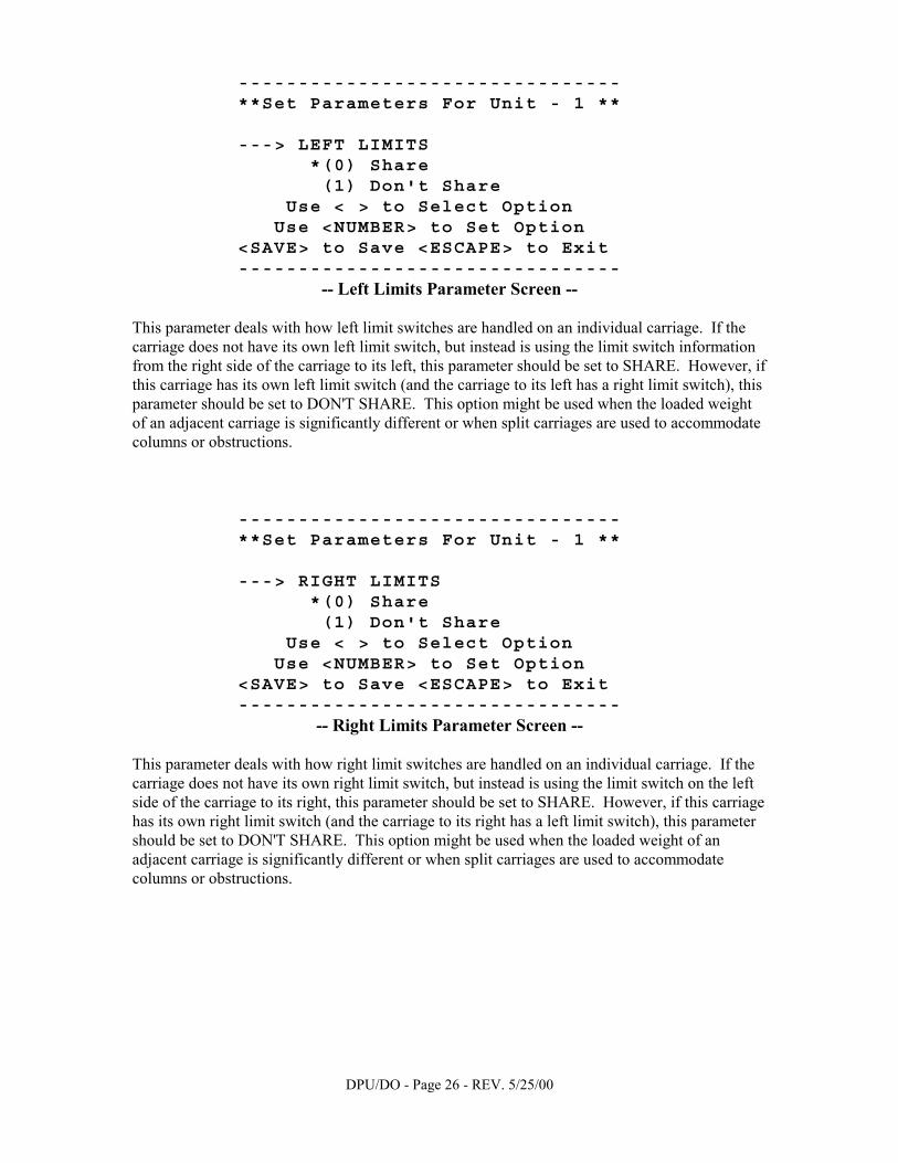
-------------------------------- **Set Parameters For Unit - 1 ** ---> LEFT LIMITS *(0) Share (1) Don't Share Use < > to Select Option Use <NUMBER> to Set Option <SAVE> to Save <ESCAPE> to Exit --------------------------------
-- Left Limits Parameter Screen -- This parameter deals with how left limit switches are handled on an individual carriage. If the carriage does not have its own left limit switch, but instead is using the limit switch information from the right side of the carriage to its left, this parameter should be set to SHARE. However, if this carriage has its own left limit switch (and the carriage to its left has a right limit switch), this parameter should be set to DON'T SHARE. This option might be used when the loaded weight of an adjacent carriage is significantly different or when split carriages are used to accommodate columns or obstructions.
-------------------------------- **Set Parameters For Unit - 1 ** ---> RIGHT LIMITS *(0) Share (1) Don't Share Use < > to Select Option Use <NUMBER> to Set Option <SAVE> to Save <ESCAPE> to Exit --------------------------------
-- Right Limits Parameter Screen -- This parameter deals with how right limit switches are handled on an individual carriage. If the carriage does not have its own right limit switch, but instead is using the limit switch on the left side of the carriage to its right, this parameter should be set to SHARE. However, if this carriage has its own right limit switch (and the carriage to its right has a left limit switch), this parameter should be set to DON'T SHARE. This option might be used when the loaded weight of an adjacent carriage is significantly different or when split carriages are used to accommodate columns or obstructions.
DPU/DO - Page 27 - REV. 5/25/00
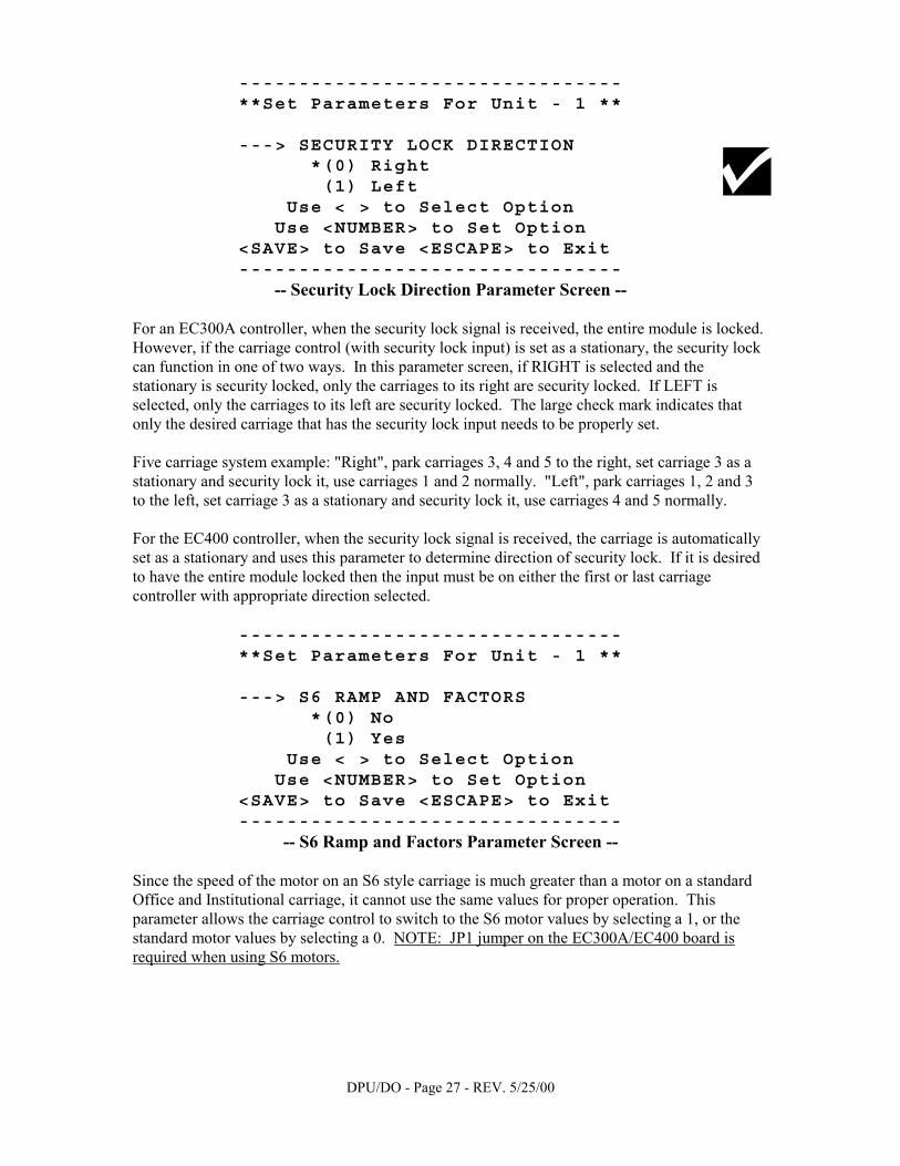
-------------------------------- **Set Parameters For Unit - 1 ** ---> SECURITY LOCK DIRECTION *(0) Right (1) Left Use < > to Select Option Use <NUMBER> to Set Option <SAVE> to Save <ESCAPE> to Exit --------------------------------
-- Security Lock Direction Parameter Screen -- For an EC300A controller, when the security lock signal is received, the entire module is locked. However, if the carriage control (with security lock input) is set as a stationary, the security lock can function in one of two ways. In this parameter screen, if RIGHT is selected and the stationary is security locked, only the carriages to its right are security locked. If LEFT is selected, only the carriages to its left are security locked. The large check mark indicates that only the desired carriage that has the security lock input needs to be properly set. Five carriage system example: "Right", park carriages 3, 4 and 5 to the right, set carriage 3 as a stationary and security lock it, use carriages 1 and 2 normally. "Left", park carriages 1, 2 and 3 to the left, set carriage 3 as a stationary and security lock it, use carriages 4 and 5 normally. For the EC400 controller, when the security lock signal is received, the carriage is automatically set as a stationary and uses this parameter to determine direction of security lock. If it is desired to have the entire module locked then the input must be on either the first or last carriage controller with appropriate direction selected.
-------------------------------- **Set Parameters For Unit - 1 ** ---> S6 RAMP AND FACTORS *(0) No (1) Yes Use < > to Select Option Use <NUMBER> to Set Option <SAVE> to Save <ESCAPE> to Exit --------------------------------
-- S6 Ramp and Factors Parameter Screen -- Since the speed of the motor on an S6 style carriage is much greater than a motor on a standard Office and Institutional carriage, it cannot use the same values for proper operation. This parameter allows the carriage control to switch to the S6 motor values by selecting a 1, or the standard motor values by selecting a 0. NOTE: JP1 jumper on the EC300A/EC400 board is required when using S6 motors.

DPU/DO - Page 28 - REV. 5/25/00
-------------------------------- **Set Parameters For Unit - 1 ** ---> SAFETY FAULT WARNING *(0) Off (1) On Use < > to Select Option Use <NUMBER> to Set Option <SAVE> to Save <ESCAPE> to Exit --------------------------------
-- Safety Fault Warning Parameter Screen -- The safety fault warning is an audible beeping sound which is heard any time the movement cycle has been interrupted by a safety activation, such as a safety sweep, aisle entry sensor or ZFS. The beeper itself is optional and is not found on all systems.
-------------------------------- **Set Parameters For Unit - 1 ** ---> POWER LINE FREQUENCY *(0) 60 Hz (1) 50 Hz Use < > to Select Option Use <NUMBER> to Set Option <SAVE> to Save <ESCAPE> to Exit --------------------------------
-- Power Line Frequency Parameter Screen -- Operation of DC motor controls varies a great deal when the power line frequency changes. This parameter screen allows the user to select the standard 60 Hz power line frequency, or the European 50 Hz frequency for proper operation in some overseas installations.
DPU/DO - Page 29 - REV. 5/25/00
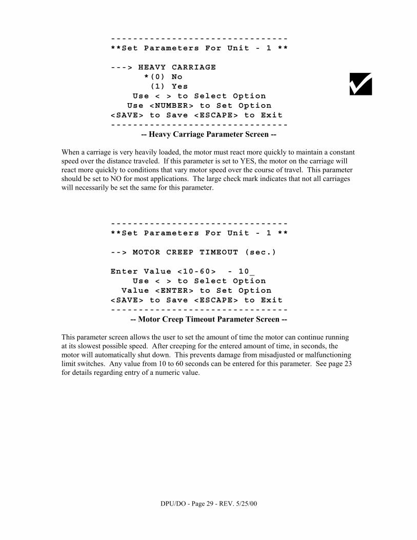
-------------------------------- **Set Parameters For Unit - 1 ** ---> HEAVY CARRIAGE *(0) No (1) Yes Use < > to Select Option Use <NUMBER> to Set Option <SAVE> to Save <ESCAPE> to Exit --------------------------------
-- Heavy Carriage Parameter Screen -- When a carriage is very heavily loaded, the motor must react more quickly to maintain a constant speed over the distance traveled. If this parameter is set to YES, the motor on the carriage will react more quickly to conditions that vary motor speed over the course of travel. This parameter should be set to NO for most applications. The large check mark indicates that not all carriages will necessarily be set the same for this parameter.
-------------------------------- **Set Parameters For Unit - 1 ** --> MOTOR CREEP TIMEOUT (sec.) Enter Value <10-60> - 10_ Use < > to Select Option Value <ENTER> to Set Option <SAVE> to Save <ESCAPE> to Exit --------------------------------
-- Motor Creep Timeout Parameter Screen -- This parameter screen allows the user to set the amount of time the motor can continue running at its slowest possible speed. After creeping for the entered amount of time, in seconds, the motor will automatically shut down. This prevents damage from misadjusted or malfunctioning limit switches. Any value from 10 to 60 seconds can be entered for this parameter. See page 23 for details regarding entry of a numeric value.
DPU/DO - Page 30 - REV. 5/25/00
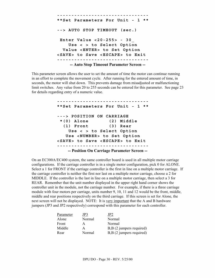
-------------------------------- **Set Parameters For Unit - 1 ** --> AUTO STOP TIMEOUT (sec.) Enter Value <20-255> - 30_ Use < > to Select Option Value <ENTER> to Set Option <SAVE> to Save <ESCAPE> to Exit --------------------------------
-- Auto Stop Timeout Parameter Screen -- This parameter screen allows the user to set the amount of time the motor can continue running in an effort to complete the movement cycle. After running for the entered amount of time, in seconds, the motor will shut down. This prevents damage from misadjusted or malfunctioning limit switches. Any value from 20 to 255 seconds can be entered for this parameter. See page 23 for details regarding entry of a numeric value.
-------------------------------- **Set Parameters For Unit - 1 ** ---> POSITION ON CARRIAGE *(0) Alone (2) Middle (1) Front (3) Rear Use < > to Select Option Use <NUMBER> to Set Option <SAVE> to Save <ESCAPE> to Exit --------------------------------
-- Position On Carriage Parameter Screen -- On an EC300A/EC400 system, the same controller board is used in all multiple motor carriage configurations. If the carriage controller is in a single motor configuration, pick 0 for ALONE. Select a 1 for FRONT if the carriage controller is the first in line on a multiple motor carriage. If the carriage controller is neither the first nor last on a multiple motor carriage, choose a 2 for MIDDLE. If the controller is the last in line on a multiple motor carriage, then select a 3 for REAR. Remember that the unit number displayed in the upper right hand corner shows the controller unit in the module, not the carriage number. For example, if there is a three carriage module with four motors per carriage, units number 9, 10, 11 and 12 would be the front, middle, middle and rear positions respectively on the third carriage. If this screen is set for Alone, the next screen will not be displayed. NOTE: It is very important that the A and B hardware jumpers (JP3 and JP2 respectively) correspond with this parameter for each controller. Parameter JP3 JP2 Alone Normal Normal Front A Normal Middle A B,B (2 jumpers required) Rear Normal B,B (2 jumpers required)
DPU/DO - Page 31 - REV. 5/25/00
-------------------------------- **Set Parameters For Unit - 1 ** --> MOTOR SKEW VALUE (counts) Enter Value <10-80> - 10_ Use < > to Select Option Value <ENTER> to Set Option <SAVE> to Save <ESCAPE> to Exit --------------------------------
-- Motor Skew Value Parameter Screen -- This screen is only shown when the POSITION ON CARRIAGE parameter is set for front, middle or rear. When dealing with multiple motor carriages, each of the motors on the carriage should move at exactly the same speed. Unfortunately, there is always some variation, a small amount of which can be tolerated. This parameter sets the amount of allowable variation between motors on the same carriage. The smaller this value can be set, with the carriage finishing its movement cycle, the better. This value can be set anywhere between 10 and 80 motor counts inclusively. HOWEVER, please consult the factory before using values that exceed 30 counts. See page 23 for details regarding entry of a numeric value.
-------------------------------- **Set Parameters For Unit - 1 ** --> START BEEP TIMEOUT (.1 sec.) Enter Value <3-50> - 3_ Use < > to Select Option Value <ENTER> to Set Option <SAVE> to Save <ESCAPE> to Exit --------------------------------
-- Start Beep Timeout Parameter Screen -- This parameter deals with the warning beep duration that occurs anytime a movement cycle is started. For most Office and Institutional systems, this value is set very low, 3 for 0.3 seconds for instance. For an S6 system, however, usually has this value set higher, for a longer audible warning before movement begins. See page 23 for details regarding entry of a numeric value.
DPU/DO - Page 32 - REV. 5/25/00
-------------------------------- **Set Parameters For Unit - 1 ** ---> AISLE LIGHT ACTIVATION *(0) Not Instant On (1) Instant On Use < > to Select Option Use <NUMBER> to Set Option <SAVE> to Save <ESCAPE> to Exit --------------------------------
-- Aisle Light Activation Parameter Screen -- This is the first of several parameters that control the operation of module lighting. If set to Not Instant On (Delayed On), the lights will only turn on in the requested aisle after the movement cycle is complete and all carriages have stopped. If set to Instant On, the lights will turn on in the requested aisle as soon as movement begins or shortly there after.
-------------------------------- **Set Parameters For Unit - 1 ** ---> AISLE/BAY LIGHT TIMING *(0) Not Timed (1) Timed Use < > to Select Option Use <NUMBER> to Set Option <SAVE> to Save <ESCAPE> to Exit --------------------------------
-- Aisle/Bay Light Timing Parameter Screen -- Aisle lights that are set to Not Timed will remain on until the user presses the reset button at the open aisle or requests another aisle. If set to be timed aisle lights will turn off after their set period of time. In most cases activating a sweep, aisle entry, safety floor, ZFS or pushing an Open Aisle button will reinitialize the timer to its set value. Whether set for timed or not timed, pushing reset at the open aisle will turn the aisle lights off. Bay lights that are set for not timed will remain on until the user presses the last accessed aisle reset button and allows the set bay light time-out to expire (EC400 turns off immediately after pushing reset). When set to be timed the bay lights will turn off after their corresponding set period of time. In most cases activating a sweep, aisle entry, safety floor, ZFS or pushing an Open Aisle button will reinitialize the bay light timer to its set value. If this screen is set for "Not Timed,” the next screen will not be displayed.

DPU/DO - Page 33 - REV. 3/14/2002
--------------------------------**Set Parameters For Unit - 1 **
--> AISLE LIGHT TIMEOUT
Enter Value <6-255> - 10_Use < > to Select Option
Value <ENTER> to Set Option<SAVE> to Save <ESCAPE> to Exit--------------------------------
-- Aisle Light Timeout Parameter Screen -- This screen is only shown if timed lights have been selected. When a mobile system is equipped with aisle lighting, and that aisle lighting is set to be timed, this parameter specifies the amount of time the aisle lights will stay on after an activation. This value can be set from 6 to 255 seconds (approximately 4.25 minutes maximum). See page 23 for details regarding entry of a numeric value.
--------------------------------**Set Parameters For Unit - 1 **
---> OPTION OUTPUT FOR*(0) Access Indicator(1) Bay Lighting
Use < > to Select OptionUse <NUMBER> to Set Option
<SAVE> to Save <ESCAPE> to Exit --------------------------------
-- Option Output For Parameter Screen -- Attention: Regarding EC400 logic only, the global �√ � applies to all other systems. When the system is equipped with bay lighting, all carriages within the system must have �bay lighting� selected. The large check mark indicates that this setting is only required on the controller that interfaces to the bay lighting control box. There is one option output on the EC300A/EC400 control board that can function as an access indicator light output or as a bay lighting control output. The access indicator signal is on when the module is moving, a safety is activated (ZFS, sweep, floor, etc.) or an aisle is locked (when set for manual reset mode). It turns off when the module is restored to the Ready For Use (all green) state. If the Bay Lighting option is selected, the signal is turned on in the same manner, however there can be some delay before the signal turns off. It will turn off when the module is restored to the Ready For Use state and after the set Bay Light Timeout value has expired (provided that the timed option is selected, see page 32). When set for not timed the bay lights will remain on until the user presses the last accessed aisle reset button and then allows the set Bay Light Timeout to expire (EC400 turns off immediately after pushing reset). If this screen is set for "Access Indicator" the next screen will not be displayed.
DPU/DO - Page 34 - REV. 5/25/00
-------------------------------- **Set Parameters For Unit - 1 ** --> BAY LIGHT TIMEOUT (sec.) Enter Value <1-255> - 10_ Use < > to Select Option Value <ENTER> to Set Option <SAVE> to Save <ESCAPE> to Exit --------------------------------
-- Bay Light Timeout Parameter Screen -- This screen is only displayed if bay lighting has been selected (regardless of timed or not timed parameter selection). When equipped with bay lighting (only the controller that has the bay lighting control box needs to be set), this parameter specifies the amount of time the bay lights will remain on after an activation. This value can be set from 1 to 255 seconds (approximately 4.25 minutes maximum). See page 23 for details regarding entry of a numeric value.
-------------------------------- **Set Parameters For Unit - 1 ** ---> ZERO FORCE SENSORS *(0) No (1) Yes Use < > to Select Option Use <NUMBER> to Set Option <SAVE> to Save <ESCAPE> to Exit --------------------------------
-- Zero Force Sensors Parameter Screen --
This parameter screen allows the user to set the system to be equipped with Zero Force Sensors (ZFS) by selecting YES. Selecting NO turns off the Zero Force Sensors option. The values displayed on the diagnostic unit are the parameters as stored in the EC300A/EC400 board, not in the ZFS board. When the SAVE function is performed all the parameters are sent to and saved on the EC300A/EC400 board, which then forwards the ZFS parameters to the ZFS controller board (if its I2C cable is plugged in, from EC300A/EC400-J24 to ZFS-J15). If the ZFS board is changed or a new I2C chip is installed, it will have to be reprogrammed. The ZFS board will toggle the right sweep relay after it receives new parameters. Pressing the HELP key at any time while in the "Set Parameters" section will display this screen. If this screen is set for "No" then the following seven ZFS screens will not be displayed.

DPU/DO - Page 35 - REV. 5/25/00
-------------------------------- **Set Parameters For Unit - 1 ** --> ZFS LEFT WEB LIGHTS Enter Value <0-255> - 12_ Use < > to Select Option Value <ENTER> to Set Option <SAVE> to Save <ESCAPE> to Exit --------------------------------
-- ZFS Left Aisle LEDs Parameter Screen -- This screen is only shown if ZFS has been selected. If the carriage is a master configured with left aisle ZFS then enter the number of LEDs. This value can be set from 0 to 255 LEDs. Zero allows for potential Quadrature only systems. See page 23 for details regarding entry of a numeric value.
-------------------------------- **Set Parameters For Unit - 1 ** --> ZFS RIGHT WEB LIGHTS Enter Value <0-255> - 12_ Use < > to Select Option Value <ENTER> to Set Option <SAVE> to Save <ESCAPE> to Exit --------------------------------
-- ZFS Right Aisle LEDs Parameter Screen -- This screen is only shown if ZFS has been selected. Enter the right aisle number of LEDs. This value can be set from 0 to 255 LEDs. See page 23 for details regarding entry of a numeric value.

DPU/DO - Page 36 - REV. 5/25/00
-------------------------------- **Set Parameters For Unit - 1 ** ---> EXCESSIVE BACKGROUND LIGHT *(0) Neither (2) Left (1) Right (3) Both Use < > to Select Option Use <NUMBER> to Set Option <SAVE> to Save <ESCAPE> to Exit --------------------------------
-- ZFS Background Light Parameter Screen -- This screen is only shown if ZFS has been selected. The ZFS controller will normally test for "no light" seen by the receivers before energizing the transmitter. If there is an exceptional amount of infrared background light the "no light" test will fail, indicating a bad transmitter and receiver pair. This parameter allows for the setting of the option to skip the "no light" test.
-------------------------------- **Set Parameters For Unit - 1 ** ---> ZFS RESET WITH KEY *(0) No Key (1) Key Required Use < > to Select Option Use <NUMBER> to Set Option <SAVE> to Save <ESCAPE> to Exit --------------------------------
-- ZFS Reset With Key Parameter Screen -- This screen is only shown if ZFS has been selected. When an aisle locks up it can normally be reset by pushing the reset button on the control head. The EC300A/EC400 sends the reset command to the ZFS controller via the I2C cable. When this parameter option is set it requires that a Program Key (also known as an ON/OFF/STAT/MOVE key) be inserted into the front control head of an EC300A of the locked aisle. Then pressing the "ON" key and the reset button together should clear the aisle. It requires pressing the reset key on the infrared "Managerial Key" for an EC400 controller system.

DPU/DO - Page 37 - REV. 5/25/00
-------------------------------- **Set Parameters For Unit - 1 ** --> ZFS PARAM 5 Enter Value <0-255> - 0_ Use < > to Select Option Value <ENTER> to Set Option <SAVE> to Save <ESCAPE> to Exit --------------------------------
-- ZFS Parameter 5 Screen -- This screen is only shown if ZFS has been selected. This option is not used at this time.
-------------------------------- **Set Parameters For Unit - 1 ** ---> ZFS SYSTEM ACCESS FOR QUADS (0) Neither (2) Rear *(1) Front (3) Both Use < > to Select Option Use <NUMBER> to Set Option <SAVE> to Save <ESCAPE> to Exit --------------------------------
-- ZFS Quadrature Usage Parameter Screen -- This screen is only shown if ZFS has been selected. This option allows for configuring dual and single entry systems with the possibility of supporting no-quad systems.
-------------------------------- **Set Parameters For Unit - 1 ** ---> ZFS ACTIVE AISLES *(0) Right Only (1) Both Use < > to Select Option Use <NUMBER> to Set Option <SAVE> to Save <ESCAPE> to Exit --------------------------------
-- ZFS Aisle Usage Parameter Screen -- This screen is only shown if ZFS has been selected. If the carriage is a master configured with left aisle ZFS then select "Both." If the carriage is a slave configuration with right aisle ZFS then select "Right Only."

DPU/DO - Page 38 - REV. 5/25/00
-------------------------------- **Set Parameters For Unit - 1 ** --->OPTION REGISTER 1-NIGHT PARK (0)Off (2)RS (4)LC (6)AC (1)LS *(3)AS (5)RC Use < > to Select Option Use <NUMBER> to Set Option <SAVE> to Save <ESCAPE> to Exit --------------------------------
-- Option Register 1 Night Park Parameter Screen -- This determines the function of the module when jumper J23 option 1 is closed on the carriage controller (usually generated by the building management system normally closed contacts, interfaced to only one controller per module - see drawing 480268.001). Locked aisles are reset and safeties remain active. 0 - Option Jumper Disabled - nothing happens when the hardware jumper is closed. 1 - Module closes to the left, evenly spaces carriages, deactivates controls, remains parked. 2 - Module closes to the right, evenly spaces carriages, deactivates controls, remains parked. 3 - Alternates direction closing, evenly spaces carriages, deactivates controls, remains parked. 4 - Module closes to the left, deactivates control heads, remains parked. 5 - Module closes to the right, deactivates control heads, remains parked. 6 - Module alternates direction closing, deactivates control heads, remains parked.
-------------------------------- **Set Parameters For Unit - 1 ** --->OPTION REGISTER 2-FIRE PARK (0)Off *(2)RS (4)LC (1)LS (3)AS (5)RC Use < > to Select Option Use <NUMBER> to Set Option <SAVE> to Save <ESCAPE> to Exit --------------------------------
-- Option Register 2 Fire Park Parameter Screen -- This determines the function of the module when jumper J23 option 2 is closed on the carriage controller (usually by the building management system normally closed contacts, interfaced to only one controller per module - see drawing 480268.001). Locked aisles are reset and safeties remain active. Note: EC400 control heads remain functional to allow fire fighting personnel access after parking. 0 - Option Jumper Disabled - nothing happens when the hardware jumper is closed. 1 - Module closes left, evenly spaces carriages, deactivates heads. 2 - Module closes right, evenly spaces carriages, deactivates heads. 3 - Module alternate direction closing, evenly spaces carriages, deactivates heads. 4 - Module closes to the left, deactivates heads. 5 - Module closes to the right, deactivates heads. On version 4.7 & later; stationary carriages are made moveable for both Night and Fire Park modes.

DPU/DO - Page 39 - REV. 5/25/00
-------------------------------- **Set Parameters For Unit - 1 ** --> OPTION VALUE 2 -Time to Park after signal (sec.) Enter Value <0-255> - 120_ Use < > to Select Option Value <ENTER> to Set Option <SAVE> to Save <ESCAPE> to Exit --------------------------------
-- Option Value 2 Parameter Screen -- This option value parameter deals with the delay before the initiation of the night park and fire park functions on the same controller that interfaces to the fire/night box. It is a value expressed in seconds. In the example above, the special function will begin only after the option jumper has been closed for two minutes. CAUTION: DO NOT SET THE VALUE TO “0” WITH MULTIPLE MOTOR CARRIAGES. See page 23 for details regarding entry of a numeric value.
-------------------------------- **Set Parameters For Unit - 1 ** --> OPTION VALUE 1-Aisle Spacing Enter Value <0-255> - 40_ Use < > to Select Option Value <ENTER> to Set Option <SAVE> to Save <ESCAPE> to Exit --------------------------------
-- Option Value 1 Aisle Spacing Parameter Screen -- This first option value parameter determines the space between carriages when the module initiates any evenly spacing function. The large check mark to the right indicates that only one controller needs to be programmed (usually the one that interfaces to the fire/night box or has been configured for an auto move option, see page 40). The value is a time expressed in tenths of seconds of carriage travel. The example above will allow the first carriage to move for four seconds before the next carriage begins to move and another four seconds for the next carriage to move. Press the HELP key for more information. See page 23 for details regarding entry of a numeric value. For EC300A systems version 4.6 and earlier use the following equation for a starting point: Aisle Spacing Parameter = (Aisle Width in inches ÷ Number of Aisles) X 2.9 For EC400 systems and EC300A systems version 4.7 and later use the following equation: Aisle Spacing Parameter = (Aisle Width in inches ÷ Number of Aisles) X 5.8

DPU/DO - Page 40 - REV. 5/25/00
-------------------------------- **Set Parameters For Unit - 1 ** --> OPTION VALUE 3 -Last Spacing Enter Value <1-255> - 6_ Use < > to Select Option Value <ENTER> to Set Option <SAVE> to Save <ESCAPE> to Exit --------------------------------
-- Option Value 3 Last Spacing Parameter Screen -- This parameter relates to the travel time of the last carriage when the system is evenly spacing. The travel time of the last carriage needs to be reduced to allow for the entire module to coast to a stop. This parameter is an amount of time, expressed in tenths of seconds, which is subtracted from the aisle spacing parameter set in option value 1. This helps make the “last” aisle spacing consistent with the others. See page 23 for details regarding entry of a numeric value.
-------------------------------- **Set Parameters For Unit - 1 ** ---> OPTION REGISTER 3-AUTO MOVE (0)Off (2)Auto (4)LS (1)Rove (3)AS (5)RS Use < > to Select Option Use <NUMBER> to Set Option <SAVE> to Save <ESCAPE> to Exit --------------------------------
-- Option Register 3 Auto Move Parameter Screen -- This option register determines the function of the system when Jumper J22 Option 3 is closed on the carriage controller. Note that "Even Spacing" is not supported by software versions prior to 4.7. The functions are listed below. If this screen is not set for "Auto Aisle" then the following "Aisle Number" screen will not be displayed. Hardware Jumper J22 Option 3 (on one controller) has to be installed for the selected feature to work. It is recommended to use only one controller to make it easier if the feature needs to be removed. The Auto Move timer is active only when the module is in the “Ready For Use” state. 0 - Option Jumper Disabled - nothing happens when the hardware jumper is closed. 1 - Roving Aisle - Module accesses a different aisle after a set time period. 2 - Auto Aisle - Module accesses a specific aisle after a set time period. 3 - * Alternate Closing then Evenly Spaces Module after set time period (rev 4.7 and later). 4 - * Close left then Evenly Spaces Module after set time period (EC400 controllers only). 5 - * Close right then Evenly Spaces Module after set time period (EC400 controllers only). * Note: To invoke any of the evenly spacing auto move functions, you have to calculate and set option value 1 (previous page), option value 3 (top of this page) and option value 4 (next page).
DPU/DO - Page 41 - REV. 5/25/00
-------------------------------- **Set Parameters For Unit - 1 ** --> OPTION VALUE 5 -Aisle Number Enter Value <1-64> - 2_ Use < > to Select Option Value <ENTER> to Set Option <SAVE> to Save <ESCAPE> to Exit --------------------------------
-- Option Value 5 - Aisle Number Parameter Screen -- This screen is only shown if Auto Aisle mode has been selected. The large check mark to the right indicates that only one controller needs to be programmed, usually the one that has been configured for an auto move option, see previous page. This option value parameter screen indicates the aisle number when used with Auto Aisle mode. This will be the aisle that is opened after the system has not been used for the time period defined by Option Value 4 (and hardware connector J22 Option 3 has a jumper). See page 23 for details regarding entry of a numeric value.
-------------------------------- **Set Parameters For Unit - 1 ** --> OPTION VALUE 4 - Timer (min) Enter Value <0-255> - 60_ Use < > to Select Option Value <ENTER> to Set Option <SAVE> to Save <ESCAPE> to Exit --------------------------------
-- Option Value 4 Timer Parameter Screen -- This option value parameter functions as a timer measured in minutes. It determines the amount of time a module must remain unused (not accessed or any safety activated) before the roving aisle, auto aisle or even spacing functions work. The large check mark to the right indicates that only one controller needs to be programmed, usually the one that has been configured for an auto move option, see previous page. See page 23 for details regarding entry of a numeric value.

DPU/DO - Page 42 - REV. 5/25/00
-------------------------------- **Set Parameters For Unit - 1 ** --> OPT REG 4 -IR OPTION (EC400) Enter Value <0-255> - 3_ Use < > to Select Option Value <ENTER> to Set Option <SAVE> to Save <ESCAPE> to Exit --------------------------------
-- EC400 Infrared Option Key Parameter Screen -- This screen pertains to and will only be displayed on systems configured with EC400 controllers. The controls provide the user with an optional infrared input, found on the managerial key. The standard supported functions are listed below. Other custom options may be added for specific customer needs. No hardware jumper is required to implement this option, however the evenly spacing parameters have to set properly to take advantage of this feature. It is also a useful tool for the installer to initially set and test the spacing parameters. 0 - IR Option Key Disabled - nothing happens when the IR option key is pressed. 1 - Module alternate direction packing, evenly spaces carriages, controls remain functional. 2 - Module closes left, evenly spaces carriages, control heads remain functional. 3 - Module closes right, evenly spaces carriages, control heads remain functional.
DPU/DO - Page 43 - REV. 5/25/00
-------------------------------- **Set Parameters For Unit - 1 ** ---> MOVE FROM SAFETY ACTIVATION *(0) No (1) Yes Use < > to Select Option Use <NUMBER> to Set Option <SAVE> to Save <ESCAPE> to Exit --------------------------------
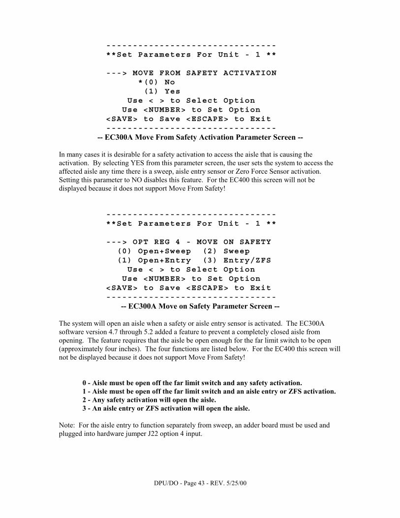
-- EC300A Move From Safety Activation Parameter Screen -- In many cases it is desirable for a safety activation to access the aisle that is causing the activation. By selecting YES from this parameter screen, the user sets the system to access the affected aisle any time there is a sweep, aisle entry sensor or Zero Force Sensor activation. Setting this parameter to NO disables this feature. For the EC400 this screen will not be displayed because it does not support Move From Safety!
-------------------------------- **Set Parameters For Unit - 1 ** ---> OPT REG 4 - MOVE ON SAFETY (0) Open+Sweep (2) Sweep (1) Open+Entry (3) Entry/ZFS Use < > to Select Option Use <NUMBER> to Set Option <SAVE> to Save <ESCAPE> to Exit --------------------------------
-- EC300A Move on Safety Parameter Screen -- The system will open an aisle when a safety or aisle entry sensor is activated. The EC300A software version 4.7 through 5.2 added a feature to prevent a completely closed aisle from opening. The feature requires that the aisle be open enough for the far limit switch to be open (approximately four inches). The four functions are listed below. For the EC400 this screen will not be displayed because it does not support Move From Safety! 0 - Aisle must be open off the far limit switch and any safety activation. 1 - Aisle must be open off the far limit switch and an aisle entry or ZFS activation. 2 - Any safety activation will open the aisle. 3 - An aisle entry or ZFS activation will open the aisle. Note: For the aisle entry to function separately from sweep, an adder board must be used and plugged into hardware jumper J22 option 4 input.
DPU/DO - Page 44 - REV. 5/25/00
POWER PRO PARAMETER SCREENS
-------------------------------- **Set Parameters For Unit - 1 ** ---> PHOTO SWEEP TYPE *(0) Photo Sweep II (1) Photo Sweep I Use < > to Select Option Use <NUMBER> to Set Option <SAVE> to Save <ESCAPE> to Exit --------------------------------
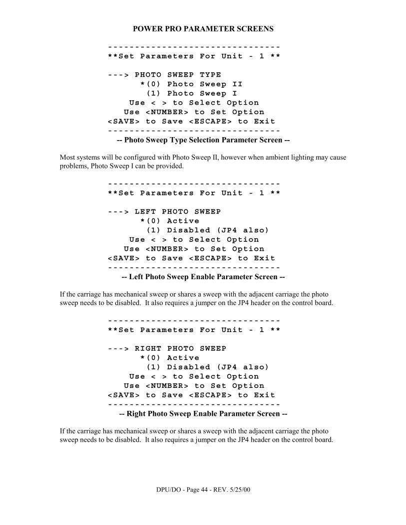
-- Photo Sweep Type Selection Parameter Screen -- Most systems will be configured with Photo Sweep II, however when ambient lighting may cause problems, Photo Sweep I can be provided.
-------------------------------- **Set Parameters For Unit - 1 ** ---> LEFT PHOTO SWEEP *(0) Active (1) Disabled (JP4 also) Use < > to Select Option Use <NUMBER> to Set Option <SAVE> to Save <ESCAPE> to Exit --------------------------------
-- Left Photo Sweep Enable Parameter Screen -- If the carriage has mechanical sweep or shares a sweep with the adjacent carriage the photo sweep needs to be disabled. It also requires a jumper on the JP4 header on the control board.
-------------------------------- **Set Parameters For Unit - 1 ** ---> RIGHT PHOTO SWEEP *(0) Active (1) Disabled (JP4 also) Use < > to Select Option Use <NUMBER> to Set Option <SAVE> to Save <ESCAPE> to Exit --------------------------------
-- Right Photo Sweep Enable Parameter Screen -- If the carriage has mechanical sweep or shares a sweep with the adjacent carriage the photo sweep needs to be disabled. It also requires a jumper on the JP4 header on the control board.

DPU/DO - Page 45 - REV. 5/25/00
POWER PRO PARAMETER SCREENS
-------------------------------- **Set Parameters For Unit - 1 ** ---> RESET MODE (0) Automatic *(1) Manual Use < > to Select Option Use <NUMBER> to Set Option <SAVE> to Save <ESCAPE> to Exit --------------------------------
-- Reset Mode Parameter Screen -- When in AUTOMATIC mode, the system will return to the Ready for Use (all green) display after moving. If the MANUAL option is selected, the system will remain "locked" on the last aisle accessed, with the Aisle in Use display on and the red LED flashing. In order to select a different aisle the user must first press the reset button at the "locked" aisle changing the system to the Ready for Use state. On the diagnostic keypad, press the LAST key to display the previous screen. Press the NEXT key to display the next screen. If this screen is set for "Automatic,” the next two screens will not be displayed.
-------------------------------- **Set Parameters For Unit - 1 ** ---> AISLE RELOCK TIMER *(0) No Relock (1) Relock Use < > to Select Option Use <NUMBER> to Set Option <SAVE> to Save <ESCAPE> to Exit --------------------------------
-- Relock Aisle Parameter Screen -- This screen is only shown if manual reset mode has been selected. This feature permits a cleared aisle to be locked again if the user does not select another aisle within the specified time. When set for “No Relock” the system remains accessible until an entry sensor, sweep or move button is activated. If this screen is set for "No Relock," the next screen will not be displayed.
DPU/DO - Page 46 - REV. 5/25/00
POWER PRO PARAMETER SCREENS
-------------------------------- **Set Parameters For Unit - 1 ** --> RELOCK TIMEOUT (seconds) Enter Value <10-255> - 10_ Use < > to Select Option Value <ENTER> to Set Option <SAVE> to Save <ESCAPE> to Exit --------------------------------
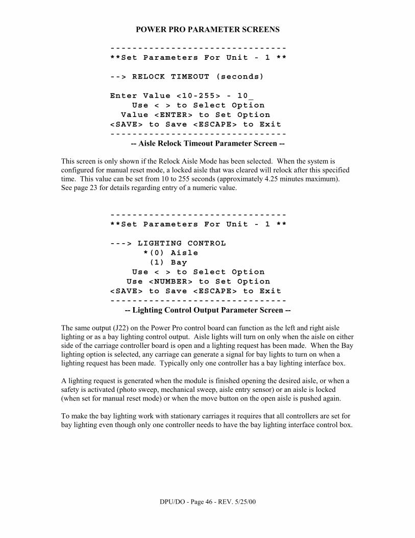
-- Aisle Relock Timeout Parameter Screen -- This screen is only shown if the Relock Aisle Mode has been selected. When the system is configured for manual reset mode, a locked aisle that was cleared will relock after this specified time. This value can be set from 10 to 255 seconds (approximately 4.25 minutes maximum). See page 23 for details regarding entry of a numeric value.
-------------------------------- **Set Parameters For Unit - 1 ** ---> LIGHTING CONTROL *(0) Aisle (1) Bay Use < > to Select Option Use <NUMBER> to Set Option <SAVE> to Save <ESCAPE> to Exit --------------------------------
-- Lighting Control Output Parameter Screen -- The same output (J22) on the Power Pro control board can function as the left and right aisle lighting or as a bay lighting control output. Aisle lights will turn on only when the aisle on either side of the carriage controller board is open and a lighting request has been made. When the Bay lighting option is selected, any carriage can generate a signal for bay lights to turn on when a lighting request has been made. Typically only one controller has a bay lighting interface box. A lighting request is generated when the module is finished opening the desired aisle, or when a safety is activated (photo sweep, mechanical sweep, aisle entry sensor) or an aisle is locked (when set for manual reset mode) or when the move button on the open aisle is pushed again. To make the bay lighting work with stationary carriages it requires that all controllers are set for bay lighting even though only one controller needs to have the bay lighting interface control box.
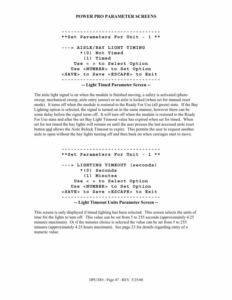
DPU/DO - Page 47 - REV. 5/25/00
POWER PRO PARAMETER SCREENS
-------------------------------- **Set Parameters For Unit - 1 ** ---> AISLE/BAY LIGHT TIMING *(0) Not Timed (1) Timed Use < > to Select Option Use <NUMBER> to Set Option <SAVE> to Save <ESCAPE> to Exit --------------------------------
-- Light Timed Parameter Screen -- The aisle light signal is on when the module is finished moving, a safety is activated (photo sweep, mechanical sweep, aisle entry sensor) or an aisle is locked (when set for manual reset mode). It turns off when the module is restored to the Ready For Use (all green) state. If the Bay Lighting option is selected, the signal is turned on in the same manner, however there can be some delay before the signal turns off. It will turn off when the module is restored to the Ready For Use state and after the set Bay Light Timeout value has expired when set for timed. When set for not timed the bay lights will remain on until the user presses the last accessed aisle reset button and allows the Aisle Relock Timeout to expire. This permits the user to request another aisle to open without the bay lights turning off and then back on when carriages start to move.
-------------------------------- **Set Parameters For Unit - 1 ** ---> LIGHTING TIMEOUT (seconds) *(0) Seconds (1) Minutes Use < > to Select Option Use <NUMBER> to Set Option <SAVE> to Save <ESCAPE> to Exit --------------------------------
-- Light Timeout Units Parameter Screen -- This screen is only displayed if timed lighting has been selected. This screen selects the units of time for the lights to turn off. This value can be set from 5 to 255 seconds (approximately 4.25 minutes maximum). Or if the minutes choice is selected the value can be set from 5 to 255 minutes (approximately 4.25 hours maximum). See page 23 for details regarding entry of a numeric value.
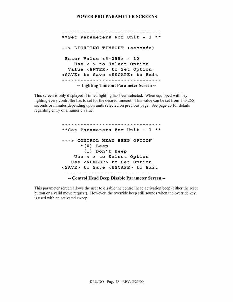
DPU/DO - Page 48 - REV. 5/25/00
POWER PRO PARAMETER SCREENS
-------------------------------- **Set Parameters For Unit - 1 ** --> LIGHTING TIMEOUT (seconds) Enter Value <5-255> - 10_ Use < > to Select Option Value <ENTER> to Set Option <SAVE> to Save <ESCAPE> to Exit --------------------------------
-- Lighting Timeout Parameter Screen -- This screen is only displayed if timed lighting has been selected. When equipped with bay lighting every controller has to set for the desired timeout. This value can be set from 1 to 255 seconds or minutes depending upon units selected on previous page. See page 23 for details regarding entry of a numeric value.
-------------------------------- **Set Parameters For Unit - 1 ** ---> CONTROL HEAD BEEP OPTION *(0) Beep (1) Don’t Beep Use < > to Select Option Use <NUMBER> to Set Option <SAVE> to Save <ESCAPE> to Exit --------------------------------
-- Control Head Beep Disable Parameter Screen -- This parameter screen allows the user to disable the control head activation beep (either the reset button or a valid move request). However, the override beep still sounds when the override key is used with an activated sweep.

DPU/DO - Page 49 - REV. 5/25/00
POWER PRO PARAMETER SCREENS
-------------------------------- **Set Parameters For Unit - 1 ** --> MOTOR CREEP TIMEOUT (sec.) Enter Value <10-31> - 10_ Use < > to Select Option Value <ENTER> to Set Option <SAVE> to Save <ESCAPE> to Exit --------------------------------
-- Motor Creep Timeout Parameter Screen -- This parameter screen allows the user to set the amount of time the motor can continue running at its slowest possible speed. After creeping for the entered amount of time, in seconds, the motor will automatically shut down. This prevents damage from miss-adjusted or malfunctioning limit switches. Any value from 10 to 31 seconds can be entered for this parameter. See page 23 for details regarding entry of a numeric value.
-------------------------------- **Set Parameters For Unit - 1 ** --> AUTO STOP TIMEOUT (sec.) Enter Value <15-63> - 30_ Use < > to Select Option Value <ENTER> to Set Option <SAVE> to Save <ESCAPE> to Exit --------------------------------
-- Auto Stop Timeout Parameter Screen -- This parameter screen allows the user to set the amount of time the motor can continue running in an effort to complete the movement cycle. After running for the entered amount of time, in seconds, the motor will shut down. This prevents damage from misadjusted or malfunctioning limit switches. Any value from 15 to 63 seconds can be entered for this parameter. See page 23 for details regarding entry of a numeric value.
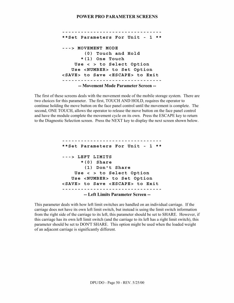
DPU/DO - Page 50 - REV. 5/25/00
POWER PRO PARAMETER SCREENS
-------------------------------- **Set Parameters For Unit - 1 ** ---> MOVEMENT MODE (0) Touch and Hold *(1) One Touch Use < > to Select Option Use <NUMBER> to Set Option <SAVE> to Save <ESCAPE> to Exit --------------------------------
-- Movement Mode Parameter Screen -- The first of these screens deals with the movement mode of the mobile storage system. There are two choices for this parameter. The first, TOUCH AND HOLD, requires the operator to continue holding the move button on the face panel control until the movement is complete. The second, ONE TOUCH, allows the operator to release the move button on the face panel control and have the module complete the movement cycle on its own. Press the ESCAPE key to return to the Diagnostic Selection screen. Press the NEXT key to display the next screen shown below.
-------------------------------- **Set Parameters For Unit - 1 ** ---> LEFT LIMITS *(0) Share (1) Don't Share Use < > to Select Option Use <NUMBER> to Set Option <SAVE> to Save <ESCAPE> to Exit --------------------------------
-- Left Limits Parameter Screen -- This parameter deals with how left limit switches are handled on an individual carriage. If the carriage does not have its own left limit switch, but instead is using the limit switch information from the right side of the carriage to its left, this parameter should be set to SHARE. However, if this carriage has its own left limit switch (and the carriage to its left has a right limit switch), this parameter should be set to DON'T SHARE. This option might be used when the loaded weight of an adjacent carriage is significantly different.
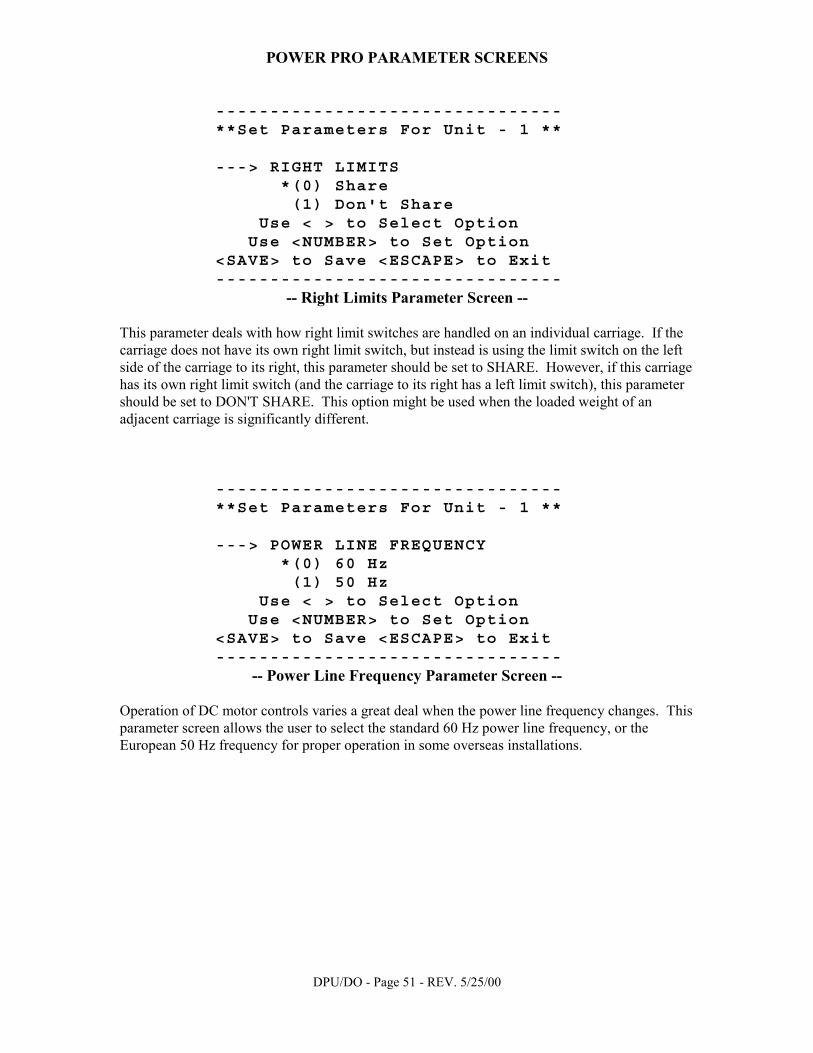
DPU/DO - Page 51 - REV. 5/25/00
POWER PRO PARAMETER SCREENS
-------------------------------- **Set Parameters For Unit - 1 ** ---> RIGHT LIMITS *(0) Share (1) Don't Share Use < > to Select Option Use <NUMBER> to Set Option <SAVE> to Save <ESCAPE> to Exit --------------------------------
-- Right Limits Parameter Screen -- This parameter deals with how right limit switches are handled on an individual carriage. If the carriage does not have its own right limit switch, but instead is using the limit switch on the left side of the carriage to its right, this parameter should be set to SHARE. However, if this carriage has its own right limit switch (and the carriage to its right has a left limit switch), this parameter should be set to DON'T SHARE. This option might be used when the loaded weight of an adjacent carriage is significantly different.
-------------------------------- **Set Parameters For Unit - 1 ** ---> POWER LINE FREQUENCY *(0) 60 Hz (1) 50 Hz Use < > to Select Option Use <NUMBER> to Set Option <SAVE> to Save <ESCAPE> to Exit --------------------------------
-- Power Line Frequency Parameter Screen -- Operation of DC motor controls varies a great deal when the power line frequency changes. This parameter screen allows the user to select the standard 60 Hz power line frequency, or the European 50 Hz frequency for proper operation in some overseas installations.

DPU/DO - Page 52 - REV. 5/25/00
How To Save Parameters When all parameter values are satisfactory, there are two methods to exit from the parameter set screens. • Pressing the SAVE key will send the new values to the Power Pro/EC300A/EC400 controller
which is addressed (displayed in upper right hand corner), and cause those new parameters to be permanent. One of two messages will be displayed depending upon the results of the save request. Either the message "Saved and Verified" or "Save Failed!" will be displayed. Pressing the ESCAPE key will exit the screen.
• Or pressing the ESCAPE key just leaves this portion of the diagnostic unit and allows the
user to select another carriage controller or safety floor monitor. NO information will be saved!

DPU/DO - Page 53 - REV. 5/25/00
Examine Hex Registers
As mentioned previously, pressing the 3 key from the Diagnostic Selection Screen sends the user to an extremely technical section of the System Diagnostic Unit. This area is called the Examine Hex Registers Area and its typical display is shown below.
-------------------------------- Unit Number -------------- 1 Register - $62 Local Address Code Hex - $02 Binary - 00000010 <UP> <DOWN> to Change Registers <NEXT> <ESCAPE> to Exit <LAST> --------------------------------
-- Examine Hex Registers Screen -- This function allows the user to inspect the values in the internal registers of the carriage controller's or safety floor monitor's internal microprocessor. In most cases this readout will be of little use on its own merits. This area could be very useful, however, if while in conversation with the factory about some anomaly, they would ask about any of the controller's internal registers. As in previous screens, the number of the unit that is being addressed is displayed in the upper right corner of the screen. The register number, in hexadecimal, along with that register's particular name is also displayed. The register's value is displayed in both hexadecimal notation and in binary. The user can select which register is being displayed by pressing the UP or DOWN keys on the keypad to sequence through all the registers. (Pressing the 1 or 7 keys will sequence the displayed register by hexadecimal 10). As seen previously, pressing the NEXT or LAST keys will change between the units being addressed. Pressing the ESCAPE key returns the user to the Diagnostic Selection screen.

DPU/DO - Page 54 - REV. 5/25/00
Remote Operation Guide
Previously it was mentioned that the System Diagnostic Unit has the capability to operate as a hard-wired remote unit. This section will describe this mode of operation in detail. Pressing the REMOTE key from the communication normal screen will place the diagnostic unit in remote operation mode and display the following screen.
-------------------------------- ################################ # SPACESAVER CORPORATION # # # # Power Pro/EC300/400 # # Remote Control # # # # Copyright 2000 # ################################ --------------------------------
-- Remote Startup Screen -- After this screen is displayed, the diagnostic unit will insure that communication with the Power Pro/EC300/EC400 module remains intact. If the diagnostic unit becomes improperly connected to the module or communication fails while the diagnostic is in remote mode, the screen shown below will appear.
-------------------------------- !!!!!!!!!!!!WARNING!!!!!!!!!!!!! ! ! ! System Not Responding ! ! ! ! Check Communication ! ! Connections ! !!!!!!!!!!!!!!!!!!!!!!!!!!!!!!!! --------------------------------
-- Communication Failure Screen -- This message indicates there are no other operations available from the diagnostic unit while in this mode because it has lost communication with the Power Pro/EC300/EC400 module. The source of trouble must be determined and corrected. By pressing the Spacesaver cube symbol on the upper left of the keypad, the System Diagnostic Unit can be sent back to the initial communication test where the problem should be able to be determined.
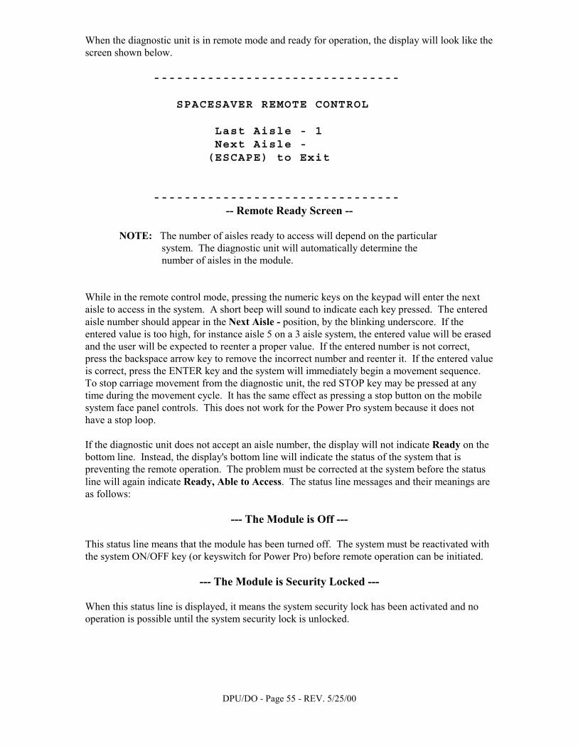
DPU/DO - Page 55 - REV. 5/25/00
When the diagnostic unit is in remote mode and ready for operation, the display will look like the screen shown below.
-------------------------------- SPACESAVER REMOTE CONTROL Last Aisle - 1 Next Aisle - (ESCAPE) to Exit --------------------------------
-- Remote Ready Screen --
NOTE: The number of aisles ready to access will depend on the particular system. The diagnostic unit will automatically determine the number of aisles in the module.
While in the remote control mode, pressing the numeric keys on the keypad will enter the next aisle to access in the system. A short beep will sound to indicate each key pressed. The entered aisle number should appear in the Next Aisle - position, by the blinking underscore. If the entered value is too high, for instance aisle 5 on a 3 aisle system, the entered value will be erased and the user will be expected to reenter a proper value. If the entered number is not correct, press the backspace arrow key to remove the incorrect number and reenter it. If the entered value is correct, press the ENTER key and the system will immediately begin a movement sequence. To stop carriage movement from the diagnostic unit, the red STOP key may be pressed at any time during the movement cycle. It has the same effect as pressing a stop button on the mobile system face panel controls. This does not work for the Power Pro system because it does not have a stop loop. If the diagnostic unit does not accept an aisle number, the display will not indicate Ready on the bottom line. Instead, the display's bottom line will indicate the status of the system that is preventing the remote operation. The problem must be corrected at the system before the status line will again indicate Ready, Able to Access. The status line messages and their meanings are as follows:
--- The Module is Off --- This status line means that the module has been turned off. The system must be reactivated with the system ON/OFF key (or keyswitch for Power Pro) before remote operation can be initiated.
--- The Module is Security Locked --- When this status line is displayed, it means the system security lock has been activated and no operation is possible until the system security lock is unlocked.
DPU/DO - Page 56 - REV. 5/25/00
--- Floor/Stop is Activated ---
This status line means that the system Safety Floor is activated or a stop push-button on one of the face panel controls is being pushed. Normally on systems equipped with safety floor, this would indicate that someone is standing in the system. In either case, the source of the activation must be removed before any operation is possible.
Accessing Aisle - 2 After a movement request is entered and the system starts its cycle, this is the status line that will appear telling the user that the requested aisle is now being opened.
Safety Fault in Aisle - 2 The system is equipped with safety sweep or any other type of aisle safety device, this status line is displayed when such devices are activated. The display indicates the number of the affected aisle as well. If the system was in motion, such a safety activation has stopped all movement within the system. If the system was not in motion, someone has accessed that aisle and activated the safety device. In either case the user must go to the indicated aisle and check the system to determine the cause of the problem. Standard operating procedures shown in the Power Pro/EC300/EC400 Operations Manual should be used to restore normal operation. Because of safety considerations, normal operation must be restored at the system before any remote operation can take place.
Must Push Reset in Aisle - 3 This final status line, when displayed, indicates that the system is set for manual reset operation and the reset push-button must be pressed at the last opened aisle before system operation is restored to the diagnostic unit. Normally, this reset operation is done at the time the accessing person leaves the last accessed aisle. While in remote operation mode, any time the operator presses the ESCAPE key, the System Diagnostic Unit will return to the normal communication screen and be ready for the next command.
OP-9825
Related Documents