TRINITRON ® COLOR TELEVISION SERVICE MANUAL BX-1L CHASSIS MODEL NAME REMOTE COMMANDER DESTINATION CHASSIS NO. 9-883-705-01 KV-29FS140 RM-YA005 LATIN NORTH SCC-S79C-A KV-29FS140 RM-YA005 LATIN SOUTH SCC-S79D-A HISTORY INFORMATION FOR THE FOLLOWING MANUAL: ORIGINAL MANUAL ISSUE DATE: 4/2006 REVISION DATE SUBJECT 4/2006 No revisions or updates are applicable at this time.

Welcome message from author
This document is posted to help you gain knowledge. Please leave a comment to let me know what you think about it! Share it to your friends and learn new things together.
Transcript
TRINITRON® COLOR TELEVISION
SERVICE MANUAL BX-1L CHASSIS MODEL NAME REMOTE COMMANDER DESTINATION CHASSIS NO.
9-883-705-01
KV-29FS140 RM-YA005 LATIN NORTH SCC-S79C-A
KV-29FS140 RM-YA005 LATIN SOUTH SCC-S79D-A
HISTORY INFORMATION FOR THE FOLLOWING MANUAL:
ORIGINAL MANUAL ISSUE DATE: 4/2006
REVISION DATE SUBJECT
4/2006 No revisions or updates are applicable at this time.
TRINITRON® COLOR TELEVISION
SERVICE MANUAL BX-1L CHASSIS MODEL NAME REMOTE COMMANDER DESTINATION CHASSIS NO.
9-883-705-01
KV-29FS140 RM-YA005 LATIN NORTH SCC-S79C-A
KV-29FS140 RM-YA005 LATIN SOUTH SCC-S79D-A
Self DiagnosisSupported model
KV-29FS140 RM-YA005
KV-29FS140
KV-29FS140 3
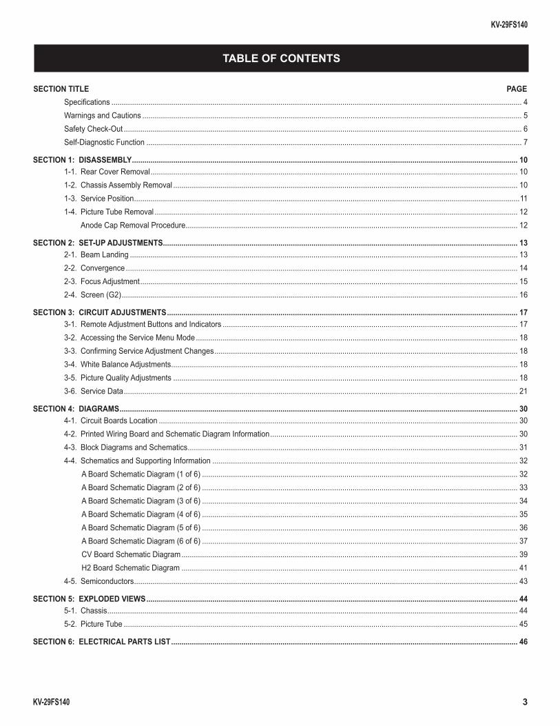
TABLE OF CONTENTS
SECTION TITLE PAGESpecifi cations ....................................................................................................................................................................................................... 4Warnings and Cautions ........................................................................................................................................................................................ 5Safety Check-Out ................................................................................................................................................................................................. 6Self-Diagnostic Function ...................................................................................................................................................................................... 7
SECTION 1: DISASSEMBLY ........................................................................................................................................................................................... 101-1. Rear Cover Removal .................................................................................................................................................................................. 101-2. Chassis Assembly Removal ....................................................................................................................................................................... 101-3. Service Position ...........................................................................................................................................................................................111-4. Picture Tube Removal ................................................................................................................................................................................ 12 Anode Cap Removal Procedure ................................................................................................................................................................. 12
SECTION 2: SET-UP ADJUSTMENTS ............................................................................................................................................................................ 132-1. Beam Landing ............................................................................................................................................................................................ 132-2. Convergence .............................................................................................................................................................................................. 142-3. Focus Adjustment ....................................................................................................................................................................................... 152-4. Screen (G2) ................................................................................................................................................................................................ 16
SECTION 3: CIRCUIT ADJUSTMENTS .......................................................................................................................................................................... 173-1. Remote Adjustment Buttons and Indicators ............................................................................................................................................... 173-2. Accessing the Service Menu Mode ............................................................................................................................................................ 183-3. Confi rming Service Adjustment Changes ................................................................................................................................................... 183-4. White Balance Adjustments ........................................................................................................................................................................ 183-5. Picture Quality Adjustments ....................................................................................................................................................................... 183-6. Service Data ............................................................................................................................................................................................... 21
SECTION 4: DIAGRAMS ................................................................................................................................................................................................. 304-1. Circuit Boards Location .............................................................................................................................................................................. 304-2. Printed Wiring Board and Schematic Diagram Information ........................................................................................................................ 304-3. Block Diagrams and Schematics ................................................................................................................................................................ 314-4. Schematics and Supporting Information .................................................................................................................................................... 32
A Board Schematic Diagram (1 of 6) ......................................................................................................................................................... 32A Board Schematic Diagram (2 of 6) ......................................................................................................................................................... 33A Board Schematic Diagram (3 of 6) ......................................................................................................................................................... 34A Board Schematic Diagram (4 of 6) ......................................................................................................................................................... 35A Board Schematic Diagram (5 of 6) ......................................................................................................................................................... 36A Board Schematic Diagram (6 of 6) ......................................................................................................................................................... 37CV Board Schematic Diagram ................................................................................................................................................................... 39H2 Board Schematic Diagram ................................................................................................................................................................... 41
4-5. Semiconductors .......................................................................................................................................................................................... 43
SECTION 5: EXPLODED VIEWS .................................................................................................................................................................................... 445-1. Chassis ....................................................................................................................................................................................................... 445-2. Picture Tube ............................................................................................................................................................................................... 45
SECTION 6: ELECTRICAL PARTS LIST ........................................................................................................................................................................ 46
KV-29FS140
KV-29FS140 4
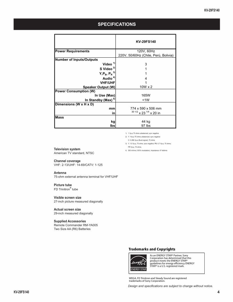
SPECIFICATIONS
1) 1 Vp-p 75 ohms unbalanced, sync negative
2) Y: 1Vp-p 75 ohms unbalanced, sync negative
C: 0.286 Vp-p (Burst signal), 75 ohms
3) Y: 1.0 Vp-p, 75 ohms, sync negative; PB: 0.7 Vp-p, 75 ohms;
PR Vp-p, 75 ohms.
4) 500 mVrms (100% modulation), Impedance: 47 kilohms
Design and specifi cations are subject to change without notice.
Television systemAmerican TV standard, NTSC
Channel coverageVHF: 2-13/UHF: 14-69/CATV: 1-125
Antenna75-ohm external antenna terminal for VHF/UHF
Picture tubeFD Trinitron® tube
Visible screen size27-inch picture measured diagonally
Actual screen size29-inch measured diagonally
Supplied AccessoriesRemote Commander RM-YA005Two Size AA (R6) Batteries
KV-29FS140
Power Requirements 120V, 60Hz220V, 50/60Hz (Chile, Perú, Bolivia)
Number of Inputs/OutputsVideo 1) 3
S Video 2) 1Y,PB, PR
3) 1Audio 4) 4
VHF/UHF 1Speaker Output (W) 10W x 2
Power Consumption (W)In Use (Max) 165W
In Standby (Max) 5) <1WDimensions (W x H x D)
mm 774 x 590 x 506 mmin 30 1/2 x 23 1/4 x 20 in
Masskg 44 kg
lbs 97 lbs
Trademarks and Copyrights
As an ENERGY STAR® Partner, Sony Corporation has determined that this product meets the ENERGY STAR® guidelines for energy efficiency. ENERGY STAR® is a U.S. registered mark.
WEGA, FD Trinitron and Steady Sound are registered trademarks of Sony Corporation.
KV-29FS140
KV-29FS140 5
WARNINGS AND CAUTIONS
CAUTION
Short circuit the anode of the picture tube and the anode cap to the metal chassis, CRT shield, or carbon painted on the CRT, after removing the anode.
WARNING!!
An isolation transformer should be used during any service to avoid possible shock hazard, because of live chassis. The chassis of this receiver is directly connected to the AC power line.
! SAFETY-RELATED COMPONENT WARNING!!
Components identifi ed by shading and ! mark on the schematic diagrams, exploded views, and in the parts list are critical for safe operation. Replace these components with Sony parts whose part numbers appear as shown in this manual or in supplements published by Sony. Circuit adjustments that are critical for safe operation are identifi ed in this manual. Follow these procedures whenever critical components are replaced or improper operation is suspected.
KV-29FS140
KV-29FS140 6
SAFETY CHECK-OUT
After correcting the original service problem, perform the following safety checks before releasing the set to the customer:
1. Check the area of your repair for unsoldered or poorly soldered connections. Check the entire board surface for solder splashes and bridges.
2. Check the interboard wiring to ensure that no wires are “pinched” or touching high-wattage resistors.
3. Check that all control knobs, shields, covers, ground straps, and mounting hardware have been replaced. Be absolutely certain that you have replaced all the insulators.
4. Look for unauthorized replacement parts, particularly transistors, that were installed during a previous repair. Point them out to the customer and recommend their replacement.
5. Look for parts which, though functioning, show obvious signs of deterioration. Point them out to the customer and recommend their replacement.
6. Check the line cords for cracks and abrasion. Recommend the replacement of any such line cord to the customer.
7. Check the B+ and HV to see if they are specifi ed values. Make sure your instruments are accurate; be suspicious of your HV meter if sets always have low HV.
8. Check the antenna terminals, metal trim, “metallized” knobs, screws, and all other exposed metal parts for AC leakage. Check leakage as described below.
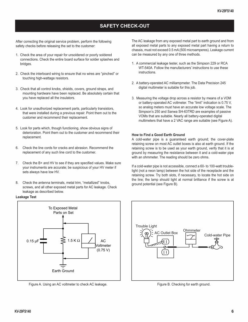
Leakage Test
The AC leakage from any exposed metal part to earth ground and from all exposed metal parts to any exposed metal part having a return to chassis, must not exceed 0.5 mA (500 microamperes). Leakage current can be measured by any one of three methods.
1. A commercial leakage tester, such as the Simpson 229 or RCA WT-540A. Follow the manufacturers’ instructions to use these instructions.
2. A battery-operated AC milliampmeter. The Data Precision 245 digital multimeter is suitable for this job.
3. Measuring the voltage drop across a resistor by means of a VOM or battery-operated AC voltmeter. The “limit” indication is 0.75 V, so analog meters must have an accurate low voltage scale. The Simpson’s 250 and Sanwa SH-63TRD are examples of passive VOMs that are suitable. Nearly all battery-operated digital multimeters that have a 2 VAC range are suitable (see Figure A).
How to Find a Good Earth GroundA cold-water pipe is a guaranteed earth ground; the cover-plate retaining screw on most AC outlet boxes is also at earth ground. If the retaining screw is to be used as your earth ground, verify that it is at ground by measuring the resistance between it and a cold-water pipe with an ohmmeter. The reading should be zero ohms.
If a cold-water pipe is not accessible, connect a 60- to 100-watt trouble- light (not a neon lamp) between the hot side of the receptacle and the retaining screw. Try both slots, if necessary, to locate the hot side on the line; the lamp should light at normal brilliance if the screw is at ground potential (see Figure B).
To Exposed Metal Parts on Set
0.15 µF 1.5 K Ω ACVoltmeter(0.75 V)
Earth Ground
Trouble Light
AC Outlet BoxOhmmeter
Cold-water Pipe
Figure A. Using an AC voltmeter to check AC leakage. Figure B. Checking for earth ground.
KV-29FS140
KV-29FS140 7
SELF-DIAGNOSTIC FUNCTION
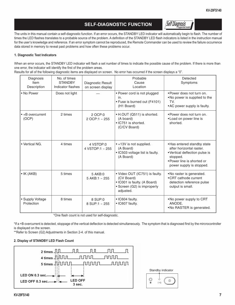
*One fl ash count is not used for self-diagnostic.
*If a +B overcurrent is detected, stoppage of the vertical defl ection is detected simultaneously. The symptom that is diagnosed fi rst by the mircrocontroller is displayed on the screen.**Refer to Screen (G2) Adjustments in Section 2-4. of this manual.
2. Display of STANDBY LED Flash Count
2 times
4 times
5 times
LED ON 0.3 sec.
LED OFF 0.3 sec. LED OFF3 sec.
Standby indicator
Self DiagnosisSupported model
The units in this manual contain a self-diagnostic function. If an error occurs, the STANDBY LED indicator will automatically begin to fl ash. The number of times the LED fl ashes translates to a probable source of the problem. A defi nition of the STANDBY LED fl ash indicators is listed in the instruction manual for the user’s knowledge and reference. If an error symptom cannot be reproduced, the Remote Commander can be used to review the failure occurrence data stored in memory to reveal past problems and how often these problems occur.
1. Diagnostic Test Indicators
When an error occurs, the STANDBY LED indicator will fl ash a set number of times to indicate the possible cause of the problem. If there is more than one error, the indicator will identify the fi rst of the problem areas.Results for all of the following diagnostic items are displayed on screen. No error has occurred if the screen displays a “0”.
DiagnosisItem
Description
• No Power
• +B overcurrent(OCP)
• Vertical NG.
• IK (AKB)
• Supply VoltageProtection
DetectedSymptoms
•Power does not turn on.•No power is supplied to theTV.
•AC power supply is faulty.
•Power does not turn on.•Load on power line isshorted.
•Has entered standby stateafter horizontal raster.
•Vertical deflection pulse isstopped.
•Power line is shorted orpower supply is stopped.
•No raster is generated.•CRT cathode currentdetection reference pulseoutput is small.
•No power supply to CRTANODE.
•No RASTER is generated.
No. of timesSTANDBY
Indicator flashes
Does not light
2 times
4 times
5 times
8 times
Diagnostic Resulton screen display
—
2 OCP:02 OCP:1 ~ 255
4 VSTOP:04 VSTOP:1 ~ 255
5 AKB:05 AKB:1 ~ 255
8 SUP:08 SUP:1 ~ 255
ProbableCause
Location
• Power cord is not pluggedin.
• Fuse is burned out (F4101)(H1 Board)
• H.OUT (Q511) is shorted.(A board)
• IC751 is shorted.(C/CV Board)
• +13V is not supplied.(A Board)
• IC503 voltage list is faulty.(A Board)
• Video OUT (IC751) is faulty.(CV Board)
• IC001 is faulty. (A Board)• Screen (G2) is improperly
adjusted.
• IC604 faulty.• IC607 faulty.
KV-29FS140
KV-29FS140 8
3. Stopping the STANDBY LED Indicator FlashTurn off the power switch on the TV main unit or unplug the power cord from the outlet to stop the STANDBY LED Indicator from fl ashing.
4. Self-Diagnostic Screen DisplayFor errors with symptoms such as “power sometimes shuts off” or “screen sometimes goes out” that cannot be confi rmed, it is possible to bring up past occurrences of failure on the screen for confi rmation.
To Bring Up Screen TestIn standby mode, press buttons on the Remote Commander sequentially, in rapid succession, as shown below:
DISPLAY Channel 5 Sound Volume - POWER
Note that this differs from entering the Service Mode (Sound Volume + ).
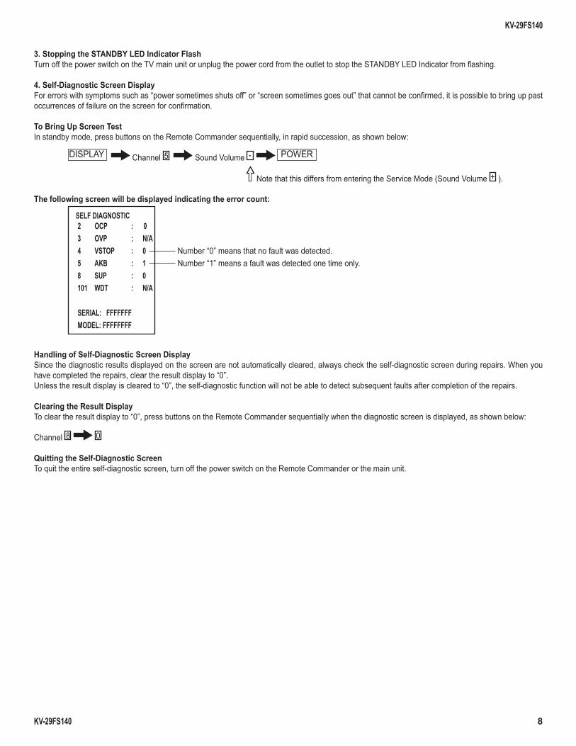
The following screen will be displayed indicating the error count:
SELF DIAGNOSTIC2 OCP : 03 OVP : N/A4 VSTOP : 0 Number “0” means that no fault was detected.5 AKB : 1 Number “1” means a fault was detected one time only.8 SUP : 0101 WDT : N/A
SERIAL: FFFFFFFMODEL: FFFFFFFF
Handling of Self-Diagnostic Screen DisplaySince the diagnostic results displayed on the screen are not automatically cleared, always check the self-diagnostic screen during repairs. When you have completed the repairs, clear the result display to “0”.Unless the result display is cleared to “0”, the self-diagnostic function will not be able to detect subsequent faults after completion of the repairs.
Clearing the Result DisplayTo clear the result display to “0”, press buttons on the Remote Commander sequentially when the diagnostic screen is displayed, as shown below:
Channel 8 0
Quitting the Self-Diagnostic ScreenTo quit the entire self-diagnostic screen, turn off the power switch on the Remote Commander or the main unit.
KV-29FS140
KV-29FS140 9
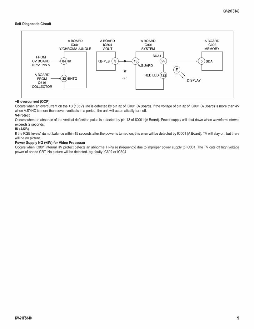
Self-Diagnostic Circuit
A BOARDIC001
Y/CHROMA JUNGLE
A BOARDIC804V.OUT
A BOARDIC001
SYSTEM
A BOARDIC003
MEMORY
FROMCV BOARDIC751 PIN 5
IK
EHTORED LED
DISPLAY
SDA1
V.GUARDSDA5F.B-PLS 3 1384
32122A BOARD
FROMQ816
COLLECTOR
99
+B overcurrent (OCP) Occurs when an overcurrent on the +B (135V) line is detected by pin 32 of IC001 (A Board). If the voltage of pin 32 of IC001 (A Board) is more than 4V when V.SYNC is more than seven verticals in a period, the unit will automatically turn off. V-Protect Occurs when an absence of the vertical defl ection pulse is detected by pin 13 of IC001 (A Board). Power supply will shut down when waveform interval exceeds 2 seconds. IK (AKB) If the RGB levels* do not balance within 15 seconds after the power is turned on, this error will be detected by IC001 (A Board). TV will stay on, but there will be no picture.Power Supply NG (+5V) for Video Processor Occurs when IC001 internal HV protect detects an abnormal H-Pulse (frequency) due to improper power supply to IC001. The TV cuts off high voltage power of anode CRT. No picture will be detected. eg: faulty IC602 or IC604
KV-29FS140
KV-29FS140 10
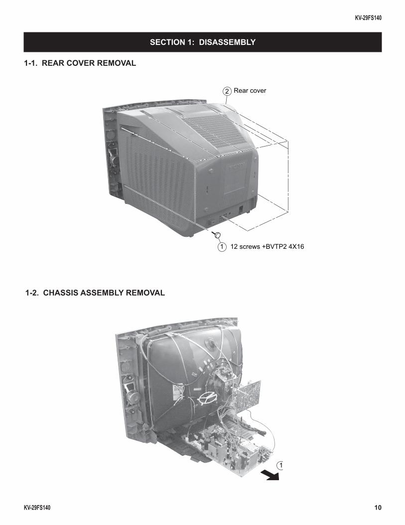
1-1. REAR COVER REMOVAL
SECTION 1: DISASSEMBLY
1-2. CHASSIS ASSEMBLY REMOVAL
1 12 screws +BVTP2 4X16
2 Rear cover
1
KV-29FS140
KV-29FS140 11
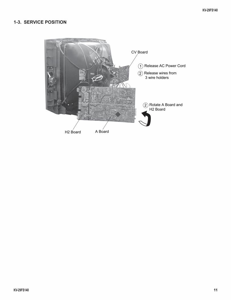
1-3. SERVICE POSITION
1 Release AC Power Cord
2 Release wires from 3 wire holders
2 Rotate A Board and H2 Board
CV Board
A Board H2 Board
KV-29FS140
KV-29FS140 12
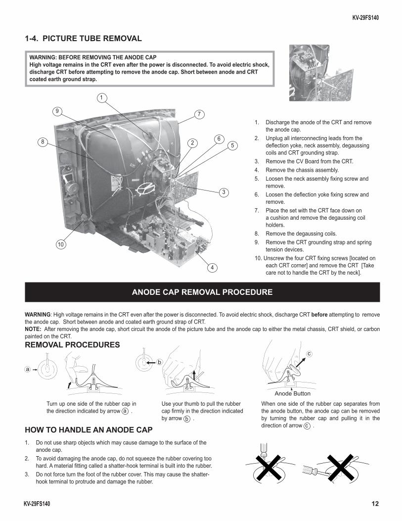
1. Discharge the anode of the CRT and remove the anode cap.
2. Unplug all interconnecting leads from the defl ection yoke, neck assembly, degaussing coils and CRT grounding strap.
3. Remove the CV Board from the CRT.4. Remove the chassis assembly.5. Loosen the neck assembly fi xing screw and
remove.6. Loosen the defl ection yoke fi xing screw and
remove.7. Place the set with the CRT face down on
a cushion and remove the degaussing coil holders.
8. Remove the degaussing coils.9. Remove the CRT grounding strap and spring
tension devices.10. Unscrew the four CRT fi xing screws [located on
each CRT corner] and remove the CRT [Take care not to handle the CRT by the neck].
1-4. PICTURE TUBE REMOVAL
WARNING: BEFORE REMOVING THE ANODE CAPHigh voltage remains in the CRT even after the power is disconnected. To avoid electric shock, discharge CRT before attempting to remove the anode cap. Short between anode and CRT coated earth ground strap.
ANODE CAP REMOVAL PROCEDURE
WARNING: High voltage remains in the CRT even after the power is disconnected. To avoid electric shock, discharge CRT before attempting to remove the anode cap. Short between anode and coated earth ground strap of CRT. NOTE: After removing the anode cap, short circuit the anode of the picture tube and the anode cap to either the metal chassis, CRT shield, or carbon painted on the CRT. REMOVAL PROCEDURES
HOW TO HANDLE AN ANODE CAP1. Do not use sharp objects which may cause damage to the surface of the
anode cap. 2. To avoid damaging the anode cap, do not squeeze the rubber covering too
hard. A material fi tting called a shatter-hook terminal is built into the rubber. 3. Do not force turn the foot of the rubber cover. This may cause the shatter-
hook terminal to protrude and damage the rubber.
Turn up one side of the rubber cap in the direction indicated by arrow a .
Use your thumb to pull the rubbercap fi rmly in the direction indicatedby arrow b .
When one side of the rubber cap separates from the anode button, the anode cap can be removed by turning the rubber cap and pulling it in the direction of arrow c .
a
b
Anode Button
c
4
1
10
9
8
7
2
3
56
KV-29FS140
KV-29FS140 13
The following adjustments should be made when a complete realignment is required or a new picture tube is installed.
These adjustments should be performed with rated power supply voltage unless otherwise noted.
Set the controls as follows unless otherwise noted:Picture control NORMALBrightness control NORMAL
SECTION 2: SET-UP ADJUSTMENTS
Perform the adjustments in order as follows: 1. Beam Landing 2. Convergence 3. Focus 4. Screen (G2) 5. White BalanceNote Test Equipment Required: 1. Color Bar Pattern Generator 2. Degausser 3. DC Power Supply 4. Digital Multimeter
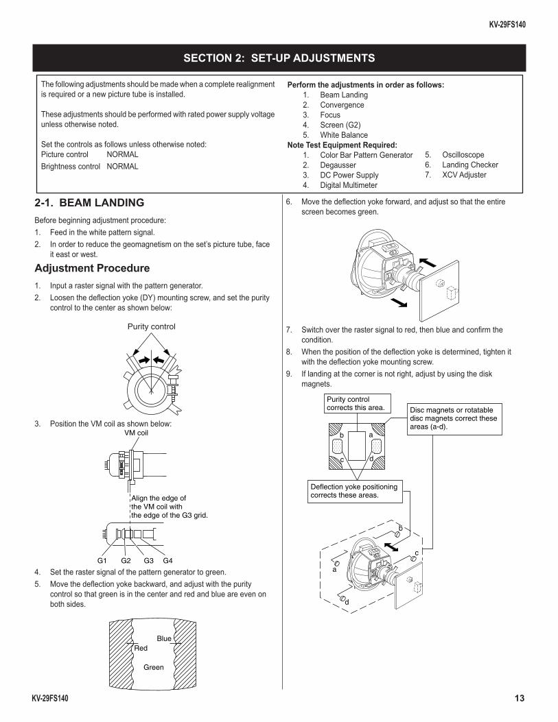
2-1. BEAM LANDINGBefore beginning adjustment procedure:1. Feed in the white pattern signal.2. In order to reduce the geomagnetism on the set’s picture tube, face
it east or west.
Adjustment Procedure1. Input a raster signal with the pattern generator.2. Loosen the defl ection yoke (DY) mounting screw, and set the purity
control to the center as shown below:
Purity control
3. Position the VM coil as shown below:VM coil
G2G1 G3
Align the edge ofthe VM coil withthe edge of the G3 grid.
G4
4. Set the raster signal of the pattern generator to green.5. Move the defl ection yoke backward, and adjust with the purity
control so that green is in the center and red and blue are even on both sides.
RedBlue
Green
6. Move the defl ection yoke forward, and adjust so that the entire screen becomes green.
7. Switch over the raster signal to red, then blue and confi rm the condition.
8. When the position of the defl ection yoke is determined, tighten it with the defl ection yoke mounting screw.
9. If landing at the corner is not right, adjust by using the disk magnets.
ab
b
c
c
d
d
a
Purity controlcorrects this area. Disc magnets or rotatable
disc magnets correct theseareas (a-d).
Deflection yoke positioningcorrects these areas.
5. Oscilloscope 6. Landing Checker 7. XCV Adjuster
KV-29FS140
KV-29FS140 14
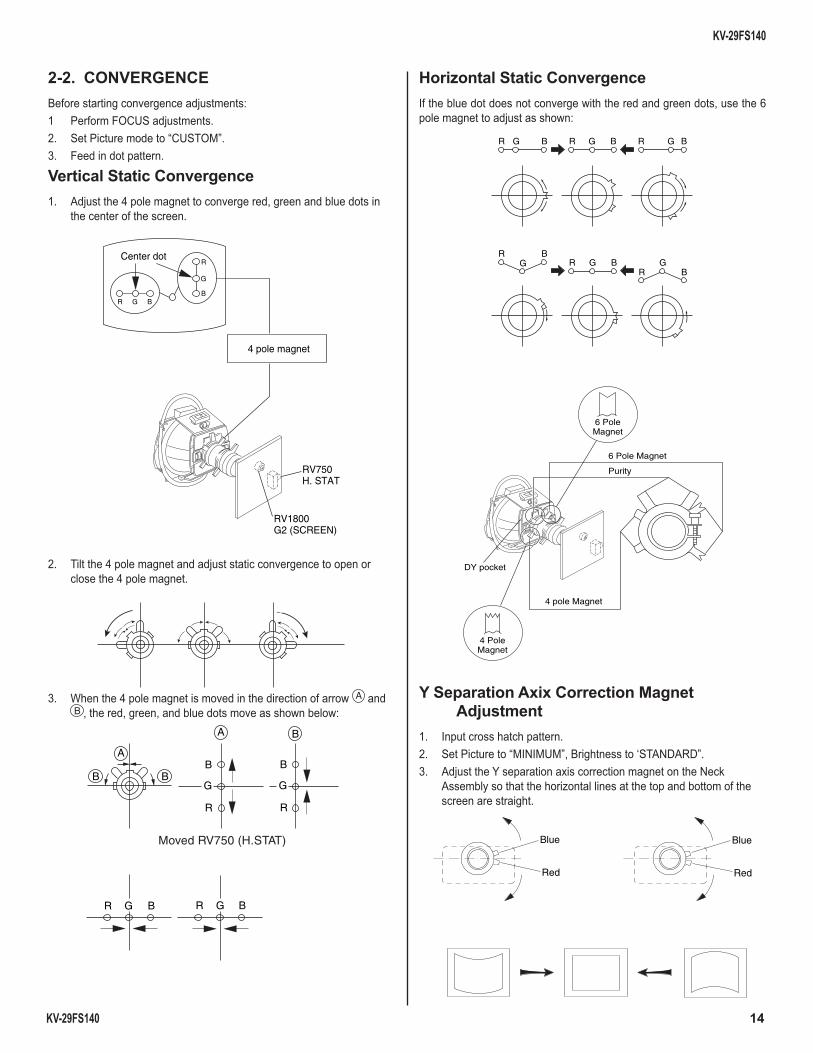
2-2. CONVERGENCEBefore starting convergence adjustments:1 Perform FOCUS adjustments.2. Set Picture mode to “CUSTOM”.3. Feed in dot pattern.
Vertical Static Convergence1. Adjust the 4 pole magnet to converge red, green and blue dots in
the center of the screen.
4 pole magnet
RV750H. STAT
RV1800G2 (SCREEN)
Center dot
R G B
G
R
B
2. Tilt the 4 pole magnet and adjust static convergence to open or close the 4 pole magnet.
3. When the 4 pole magnet is moved in the direction of arrow A and B , the red, green, and blue dots move as shown below:
Moved RV750 (H.STAT)
R R
G G
B B
A
A
B
B B
BR GG RB
Horizontal Static ConvergenceIf the blue dot does not converge with the red and green dots, use the 6 pole magnet to adjust as shown:
R G B R G B R G B
R BR GG GB
R B
6 Pole Magnet
4 pole Magnet
DY pocket
Purity
6 PoleMagnet
4 PoleMagnet
Y Separation Axix Correction Magnet Adjustment
1. Input cross hatch pattern.2. Set Picture to “MINIMUM”, Brightness to ‘STANDARD”.3. Adjust the Y separation axis correction magnet on the Neck
Assembly so that the horizontal lines at the top and bottom of the screen are straight.
Red
Blue
Red
Blue
KV-29FS140
KV-29FS140 15
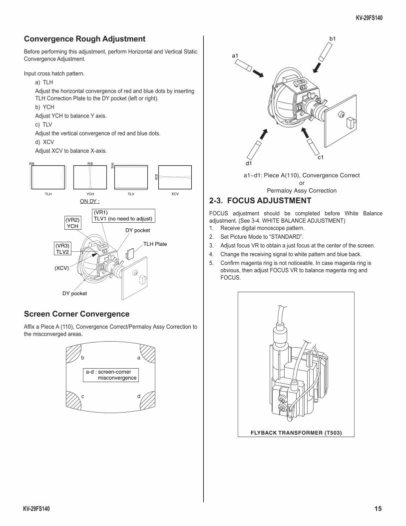
Convergence Rough AdjustmentBefore performing this adjustment, perform Horizontal and Vertical Static Convergence Adjustment.
Input cross hatch pattern. a) TLH Adjust the horizontal convergence of red and blue dots by inserting
TLH Correction Plate to the DY pocket (left or right). b) YCH Adjust YCH to balance Y axis. c) TLV Adjust the vertical convergence of red and blue dots. d) XCV Adjust XCV to balance X-axis.
TLV
RB
YCH
RB
XCV
BR
TLH
BR
(VR1)TLV1 (no need to adjust)
DY pocket
DY pocket
TLH Plate(VR3)TLV2
(XCV)
(VR2)YCH
ON DY :
Screen Corner ConvergenceAffi x a Piece A (110), Convergence Correct/Permaloy Assy Correction to the misconverged areas.
b a
c d
a-d : screen-corner misconvergence
a1
b1
c1d1
a1~d1: Piece A(110), Convergence Corrector
Permaloy Assy Correction
2-3. FOCUS ADJUSTMENTFOCUS adjustment should be completed before White Balance adjustment. (See 3-4. WHITE BALANCE ADJUSTMENT)1. Receive digital monoscope pattern.2. Set Picture Mode to “STANDARD”.3. Adjust focus VR to obtain a just focus at the center of the screen.4. Change the receiving signal to white pattern and blue back.5. Confi rm magenta ring is not noticeable. In case magenta ring is
obvious, then adjust FOCUS VR to balance magenta ring and FOCUS.
FLYBACK TRANSFORMER (T503)
KV-29FS140
KV-29FS140 16
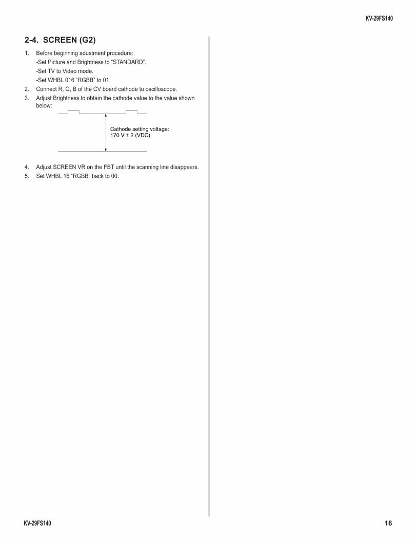
2-4. SCREEN (G2)1. Before beginning adustment procedure: -Set Picture and Brightness to “STANDARD”. -Set TV to Video mode. -Set WHBL 016 “RGBB” to 012. Connect R, G, B of the CV board cathode to oscilloscope.3. Adjust Brightness to obtain the cathode value to the value shown
below:
Cathode setting voltage:170 V ± 2 (VDC)
4. Adjust SCREEN VR on the FBT until the scanning line disappears.5. Set WHBL 16 “RGBB” back to 00.
KV-29FS140
KV-29FS140 17
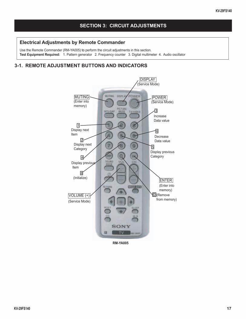
3-1. REMOTE ADJUSTMENT BUTTONS AND INDICATORS
MUTING(Enter into memory)
8(Initialize)
5Display previous Category
3Increase Data value
0(Remove from memory)
ENTER(Enter into memory)
6Decrease Data value
1Display next Item
2Display next Category
4Display previous Item
DISPLAY(Service Mode)
POWER(Service Mode)
VOLUME (+)(Service Mode)
RM-YA005
SECTION 3: CIRCUIT ADJUSTMENTS
Electrical Adjustments by Remote CommanderUse the Remote Commander (RM-YA005) to perform the circuit adjustments in this section.Test Equipment Required: 1. Pattern generator 2. Frequency counter 3. Digital multimeter 4. Audio oscillator
KV-29FS140
KV-29FS140 18
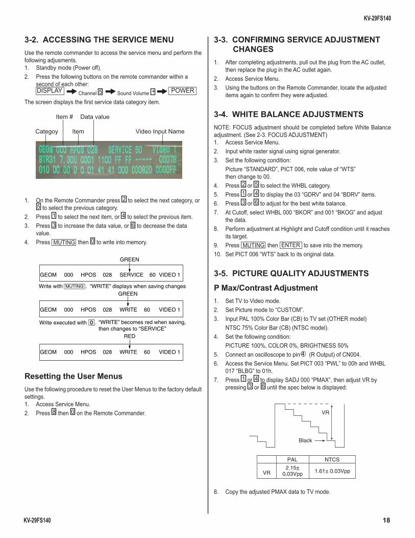
3-2. ACCESSING THE SERVICE MENUUse the remote commander to access the service menu and perform the following adjusments.1. Standby mode (Power off).2. Press the following buttons on the remote commander within a
second of each other: DISPLAY Channel 5 Sound Volume + POWERThe screen displays the fi rst service data category item.
Item #
Categoy Item
Data value
Video Input Name
1. On the Remote Commander press 2 to select the next category, or 5 to select the previous category.
2. Press 1 to select the next item, or 4 to select the previous item.3. Press 3 to increase the data value, or 6 to decrease the data
value.4. Press MUTING then 0 to write into memory.
GREEN
GEOM 000 HPOS 028 SERVICE 60 VIDEO 1
VIDEO 1
VIDEO 1
Write with [MUTING].GREEN
GEOM 000 HPOS 028 WRITE 60
GEOM 000 HPOS 028 WRITE 60
Write executed with -.
RED
“WRITE” becomes red when saving, then changes to “SERVICE”
“WRITE” displays when saving changes
Resetting the User MenusUse the following procedure to reset the User Menus to the factory default settings.1. Access Service Menu.2. Press 8 then 0 on the Remote Commander.
3-3. CONFIRMING SERVICE ADJUSTMENT CHANGES
1. After completing adjustments, pull out the plug from the AC outlet, then replace the plug in the AC outlet again.
2. Access Service Menu.3. Using the buttons on the Remote Commander, locate the adjusted
items again to confi rm they were adjusted.
3-4. WHITE BALANCE ADJUSTMENTSNOTE: FOCUS adjustment should be completed before White Balance adjustment. (See 2-3. FOCUS ADJUSTMENT)1. Access Service Menu.2. Input white raster signal using signal generator.3. Set the following condition: Picture “STANDARD”, PICT 006, note value of “WTS”
then change to 00.4. Press 2 or 5 to select the WHBL category.5. Press 1 or 4 to display the 03 “GDRV” and 04 “BDRV” items.6. Press 3 or 6 to adjust for the best white balance.7. At Cutoff, select WHBL 000 “BKOR” and 001 “BKOG” and adjust
the data.8. Perform adjustment at Highlight and Cutoff condition until it reaches
its target.9. Press MUTING then ENTER to save into the memory.10. Set PICT 006 “WTS” back to its original data.
3-5. PICTURE QUALITY ADJUSTMENTS
P Max/Contrast Adjustment1. Set TV to Video mode.2. Set Picture mode to “CUSTOM”.3. Input PAL 100% Color Bar (CB) to TV set (OTHER model) NTSC 75% Color Bar (CB) (NTSC model).4. Set the following condition: PICTURE 100%, COLOR 0%, BRIGHTNESS 50%5. Connect an oscilloscope to pin 4 (R Output) of CN004.6. Access the Service Menu. Set PICT 003 “PWL” to 00h and WHBL
017 “BLBG” to 01h.7. Press 1 or 4 to display SADJ 000 “PMAX”, then adjust VR by
pressing 3 or 6 until the spec below is displayed:
VR
Black
VR
PAL NTCS
1.61 0.03Vpp
8. Copy the adjusted PMAX data to TV mode.
KV-29FS140
KV-29FS140 19
9. Select Wide Mode to “ON” in TV and Video mode and write “PMAX” data - 6 steps (for models with V-Compression features only).
10. Press MUTING then 0 to write into memory.11. Set “PWL” and “BLBG” back to initial data. (“PWL”: 01h and “BLBG”: 00h)12. Press MUTING then 0 to write into memory.
Sub Color Adjustment1. Set TV to Video mode.2. Set Picture mode to “CUSTOM”.3. Input PAL 100% Color Bar (CB) to TV.4. Set the following condition: PICTURE 100%, COLOR 50%, BRIGHTNESS 50%, HUE 50%,
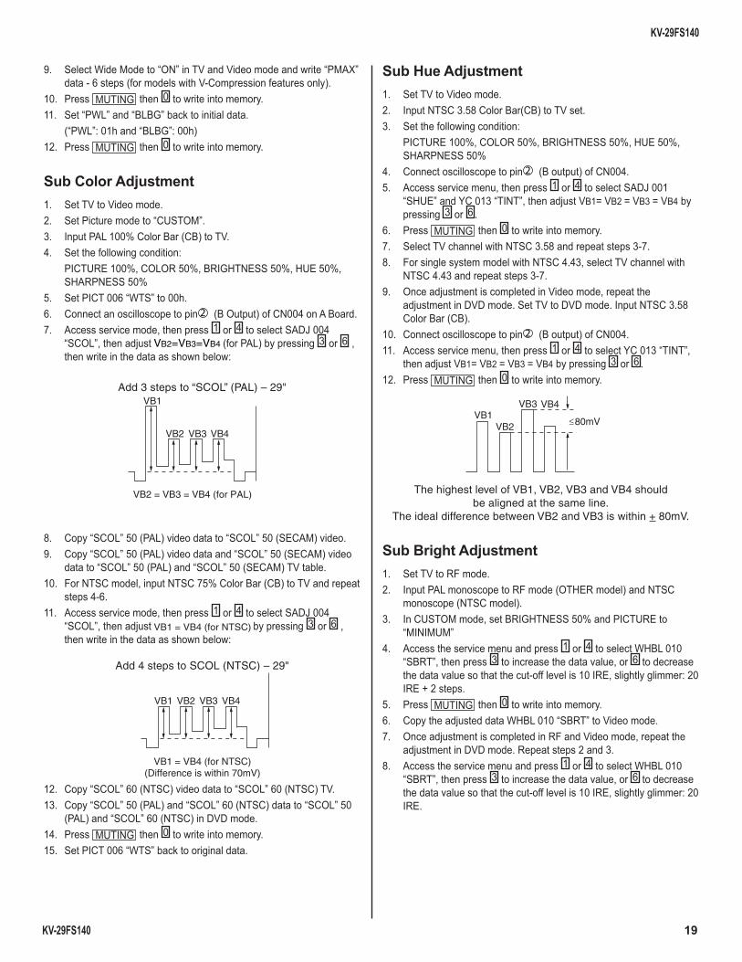
SHARPNESS 50%5. Set PICT 006 “WTS” to 00h.6. Connect an oscilloscope to pin 2 (B Output) of CN004 on A Board.7. Access service mode, then press 1 or 4 to select SADJ 004
“SCOL”, then adjust VB2=VB3=VB4 (for PAL) by pressing 3 or 6 , then write in the data as shown below:
Add 3 steps to “SCOL” (PAL) – 29"
VB2 = VB3 = VB4 (for PAL)
VB1
VB2 VB3 VB4
8. Copy “SCOL” 50 (PAL) video data to “SCOL” 50 (SECAM) video.9. Copy “SCOL” 50 (PAL) video data and “SCOL” 50 (SECAM) video
data to “SCOL” 50 (PAL) and “SCOL” 50 (SECAM) TV table.10. For NTSC model, input NTSC 75% Color Bar (CB) to TV and repeat
steps 4-6.11. Access service mode, then press 1 or 4 to select SADJ 004
“SCOL”, then adjust VB1 = VB4 (for NTSC) by pressing 3 or 6 , then write in the data as shown below:
Add 4 steps to SCOL (NTSC) – 29"
VB1 = VB4 (for NTSC)(Difference is within 70mV)
VB1 VB2 VB3 VB4
12. Copy “SCOL” 60 (NTSC) video data to “SCOL” 60 (NTSC) TV.13. Copy “SCOL” 50 (PAL) and “SCOL” 60 (NTSC) data to “SCOL” 50
(PAL) and “SCOL” 60 (NTSC) in DVD mode.14. Press MUTING then 0 to write into memory.15. Set PICT 006 “WTS” back to original data.
Sub Hue Adjustment1. Set TV to Video mode.2. Input NTSC 3.58 Color Bar(CB) to TV set.3. Set the following condition: PICTURE 100%, COLOR 50%, BRIGHTNESS 50%, HUE 50%,
SHARPNESS 50%4. Connect oscilloscope to pin 2 (B output) of CN004.5. Access service menu, then press 1 or 4 to select SADJ 001
“SHUE” and YC 013 “TINT”, then adjust VB1= VB2 = VB3 = VB4 by pressing 3 or 6 .
6. Press MUTING then 0 to write into memory.7. Select TV channel with NTSC 3.58 and repeat steps 3-7.8. For single system model with NTSC 4.43, select TV channel with
NTSC 4.43 and repeat steps 3-7.9. Once adjustment is completed in Video mode, repeat the
adjustment in DVD mode. Set TV to DVD mode. Input NTSC 3.58 Color Bar (CB).
10. Connect oscilloscope to pin 2 (B output) of CN004.11. Access service menu, then press 1 or 4 to select YC 013 “TINT”,
then adjust VB1= VB2 = VB3 = VB4 by pressing 3 or 6 .12. Press MUTING then 0 to write into memory.
The highest level of VB1, VB2, VB3 and VB4 shouldbe aligned at the same line.
The ideal difference between VB2 and VB3 is within + 80mV.
VB1VB2
VB3 VB4
80mV
Sub Bright Adjustment1. Set TV to RF mode.2. Input PAL monoscope to RF mode (OTHER model) and NTSC
monoscope (NTSC model).3. In CUSTOM mode, set BRIGHTNESS 50% and PICTURE to
“MINIMUM”4. Access the service menu and press 1 or 4 to select WHBL 010
“SBRT”, then press 3 to increase the data value, or 6 to decrease the data value so that the cut-off level is 10 IRE, slightly glimmer: 20 IRE + 2 steps.
5. Press MUTING then 0 to write into memory.6. Copy the adjusted data WHBL 010 “SBRT” to Video mode.7. Once adjustment is completed in RF and Video mode, repeat the
adjustment in DVD mode. Repeat steps 2 and 3.8. Access the service menu and press 1 or 4 to select WHBL 010
“SBRT”, then press 3 to increase the data value, or 6 to decrease the data value so that the cut-off level is 10 IRE, slightly glimmer: 20 IRE.
KV-29FS140
KV-29FS140 20
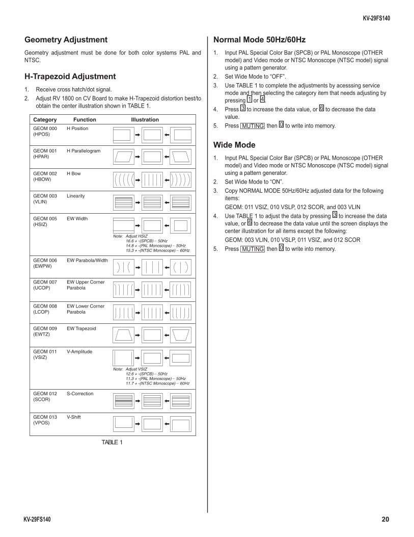
Geometry AdjustmentGeometry adjustment must be done for both color systems PAL and NTSC.
H-Trapezoid Adjustment1. Receive cross hatch/dot signal.2. Adjust RV 1800 on CV Board to make H-Trapezoid distortion best/to
obtain the center illustration shown in TABLE 1.
Category Function Illustration
GEOM 000 H Position(HPOS)
GEOM 001 H Parallelogram(HPAR)
GEOM 002 H Bow(HBOW)
GEOM 003 Linearity(VLIN)
GEOM 005 EW Width(HSIZ)
Note: Adjust HSIZ 16.6 + -(SPCB) _ 50Hz14.8 + -(PAL Monoscope) _ 50Hz15.3 + -(NTSC Monoscope) _ 60Hz
GEOM 006 EW Parabola/Width(EWPW)
GEOM 007 EW Upper Corner(UCOP) Parabola
GEOM 008 EW Lower Corner(LCOP) Parabola
GEOM 009 EW Trapezoid(EWTZ)
GEOM 011 V-Amplitude(VSIZ)
Note: Adjust VSIZ 12.6 + -(SPCB) _ 50Hz11.3 + -(PAL Monoscope) _ 50Hz11.7 + -(NTSC Monoscope) _ 60Hz
GEOM 012 S-Correction(SCOR)
GEOM 013 V-Shift(VPOS)
TABLE 1
Normal Mode 50Hz/60Hz1. Input PAL Special Color Bar (SPCB) or PAL Monoscope (OTHER
model) and Video mode or NTSC Monoscope (NTSC model) signal using a pattern generator.
2. Set Wide Mode to “OFF”.3. Use TABLE 1 to complete the adjustments by acesssing service
mode and then selecting the category item that needs adjusting by pressing 1 or 4 .
4. Press 3 to increase the data value, or 6 to decrease the data value.
5. Press MUTING then 0 to write into memory.
Wide Mode1. Input PAL Special Color Bar (SPCB) or PAL Monoscope (OTHER
model) and Video mode or NTSC Monoscope (NTSC model) signal using a pattern generator.
2. Set Wide Mode to “ON”.3. Copy NORMAL MODE 50Hz/60Hz adjusted data for the following
items: GEOM: 011 VSIZ, 010 VSLP, 012 SCOR, and 003 VLIN4. Use TABLE 1 to adjust the data by pressing 3 to increase the data
value, or 6 to decrease the data value until the screen displays the center illustration for all items except the following:
GEOM: 003 VLIN, 010 VSLP, 011 VSIZ, and 012 SCOR5. Press MUTING then 0 to write into memory.
21
KV-29FS140
KV-29FS140
Category No. Name Function COMMON (4:3) 50 (4:3) 60 (4:3) w50 (4:3) w60
! "# "$ % &'() &*' + , , , , &- &** ! (. ##/# ## #01#/# ! , ! 2- #233- 0 % , !% '- #'$- 0 ! !% !, #4. #435 % &' &*3& &(. &*35/ % , - 6-* - & &*& % , &. &*.&. ! "' "" 7 / #"8 4 #/" 7 #"8 #" 4 #/" 7 #" % "' 9*" 7 , -: -3+/!1)&
Col Temp Col Temp Col Temp Col Temp Col Temp Col Temp(Cool other) (Warm Other) (Neutral other) (Cool YUV) (Warm YUV) (Neutral YUV)
#"' "; "*7'9<8"=><"8"= "; "*7'9< ?& # ?& # ! ! "?& # " % % ! ' " < < < % " < "" , )8 < < "4 506" << % ! ! " 506" <<<( * ' 0 '3 ---+< ' * -5 ---+< ;" "*7-5 0 ! -" - @5 *"-5 ' "" "" 7 "'" " 7 "5A 535 % 8" "*7'9<"5 , )" ) //" <<< #" -43< B>B)>>B'$
VideoCategory No. Name Function Pic Mode 2 TV50pal(Video) Pic mode 0 Pic mode 150pal(TV)Common YUV
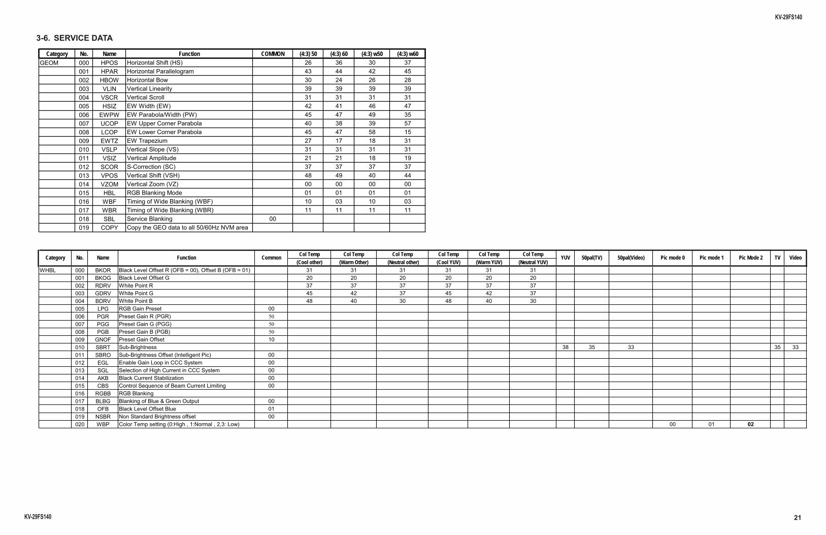
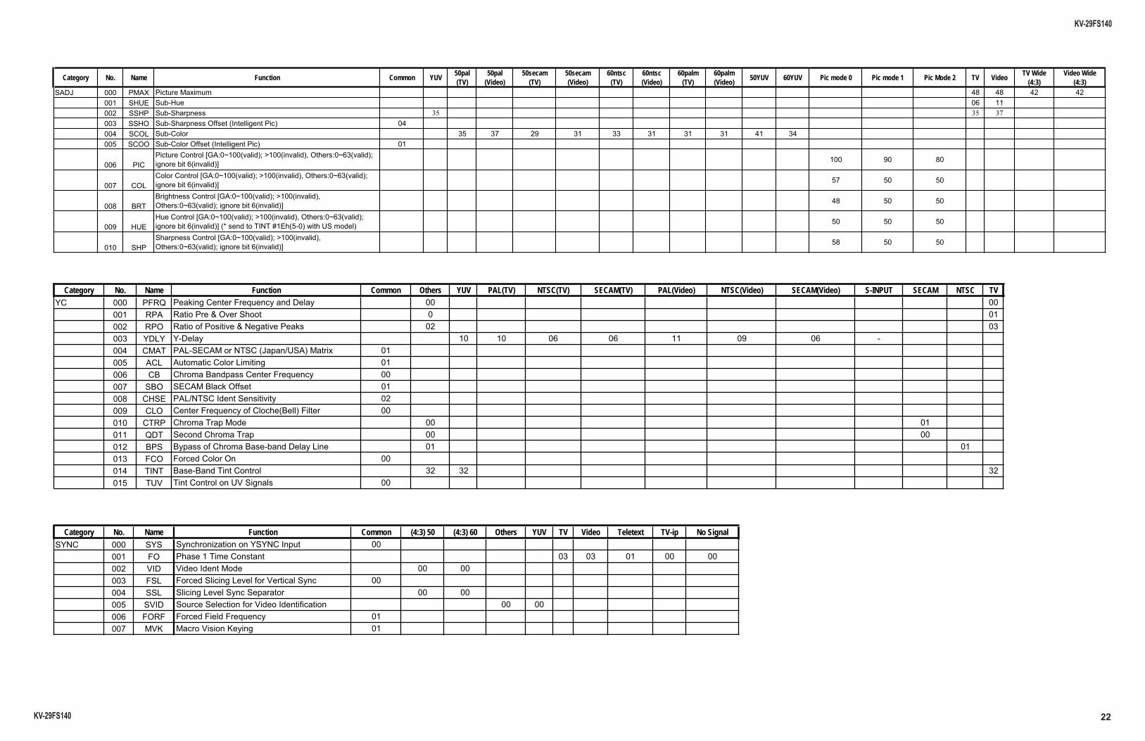
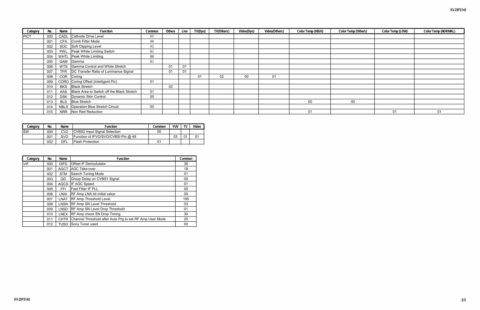
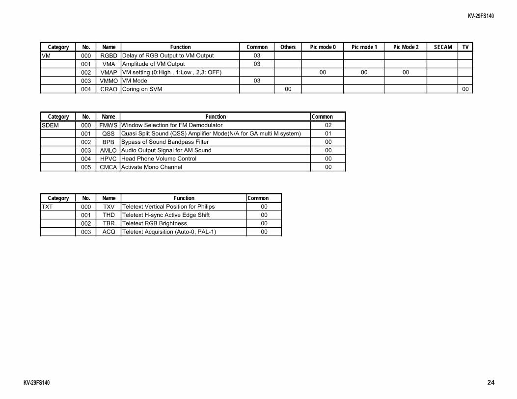
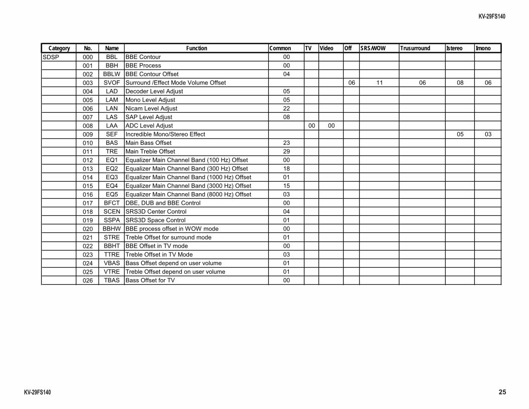
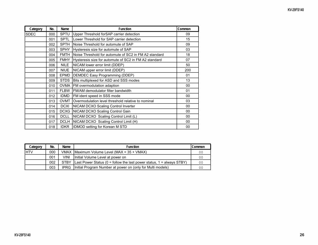
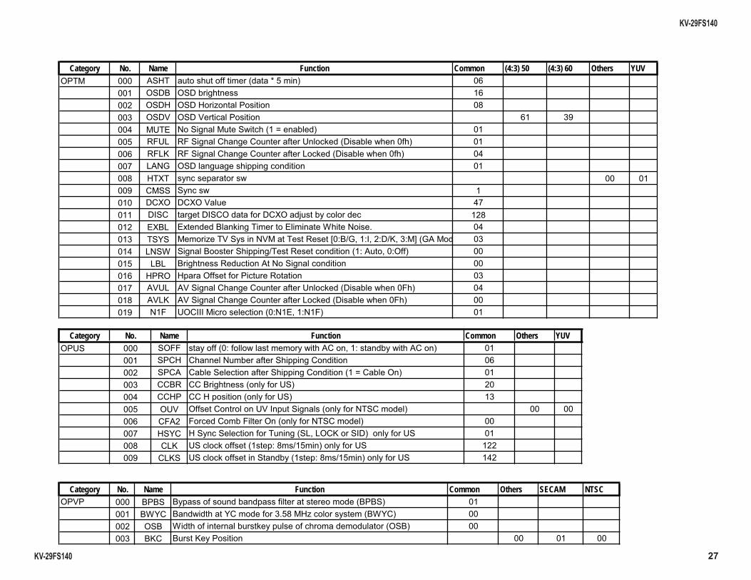
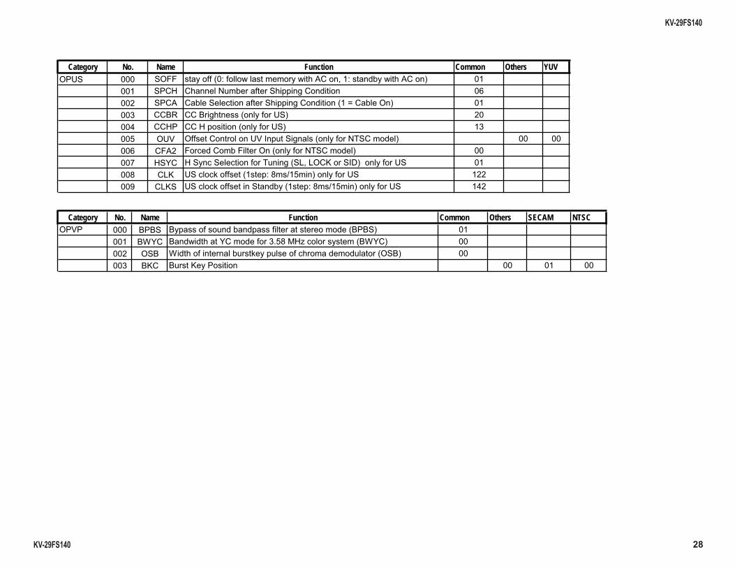
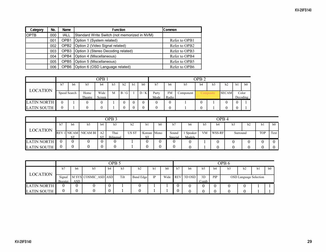
3-6. SERVICE DATA
22
KV-29FS140
KV-29FS140
Category No. Name Function Common YUV50pal(TV)
50pal(Video)
50secam(TV)
50secam(Video)
60ntsc(TV)
60ntsc(Video)
60palm(TV)
60palm(Video)
50YUV 60YUV Pic mode 0 Pic mode 1 Pic Mode 2 TV VideoTV Wide
(4:3)Video Wide
(4:3)?C D *5E5 % %
2 5065 5063 << 5063 <<<( * -' 506- ! , ! - 506-<( *
(-*5- FBG9/HI 9/><BG9/H 0 9/J , %
-'-- FBG9/HI 9/><BG9/H 0 9/J ! ! !
% "4" <<- FBG9/HI 9/><BG9/H 0 9/J % ! !
, 25- FBG9/HI 9/><BG9/H 0 9/JK< /4()4L!6$2/ ! ! !
3 <<- FBG9/HI 9/><BG9/H 0 9/J !% ! !
Category No. Name Function Common Others YUV PAL(TV) NTSC(TV) SECAM(TV) PAL(Video) NTSC(Video) SECAM(Video) S-INPUT SECAM NTSC TV:- 8M 7 - 8@5 *+ /?+
A9 <9A)97< :?': :6?+ , 6 -4 '6-)4-C3 12E ! -' 5*-' -" -" /3<<- 8@5 *+ " -"*7< % - '1)4-(/ <9+ , -' - 8@5 *+-*"8 -4 -43/ M?4 * /-43 " "+3<<-"<60 /?+' 8- 8*/- 4()4 "<6" /4 - ! 42& 4 - 2& <
Category No. Name De Function Common (4:3) 50 (4:3) 60 Others YUV TV Video Teletext TV-ip No Signal:)- : + * ::)-( 35
8 <4- < &(? &/(/ / 8' 8*/* '9&*+ * ' * '9+ *3 ! &(? 5** &/(/ * 88 8*/8/8@5 *+ &; *&< ;+
23
KV-29FS140
KV-29FS140
Category No. Name Function Common Others Live TV(Dyn) TV(Others) Video(Dyn) Video(Others) Color Temp (HIGH) Color Temp (Others) Color Temp (LOW) Color Temp (NORMAL)(-4 -?' -/?9'9
-8 -08/ - -33 '9 #' 7#' $* #4' 7#' ! #4 - /#* 48 ?-4 <'5 * % - - , - - <( * "; "*7* "*7$*"*7* ?; ?+ *7 - "' "5* )"' 3 "5*-*5 ! ) ) //5*
Category No. Name Function Common YUV TV Video# -& -&"( 35 *
& 85 * (8&1&1-&"( N % ?8' 8<*
Category No. Name Function Common&(8 (8? <(8?/5
-4 -4769 % 4 *45 / ? 53?+ -&" - (8-3/ ! 88( 8<8(8'' ')( 83')0 95 ')4 834</'9 ,!% ')) 83)'94</ , ')? 83)'9?34</ ')D 83**7)?34 -4 - 4</5<832</ ! 42 +45 5</
24
KV-29FS140
KV-29FS140
Category No. Name Function Common Others Pic mode 0 Pic mode 1 Pic Mode 2 SECAM TV
!"# $""%%& ' ( ( ) *
Category No. Name Function Common*+ %,* , $*- )% )
.** .** .**&) /0 )& * %) # * )* ' ( ! ( ) 1 (( -2 (!
Category No. Name Function Common343 34 35)- )!
3 35 6--2+*! 3 35)! (. 35-7 6"#6&
25
KV-29FS140
KV-29FS140
Category No. Name Function Common TV Video Off SRS/WOW Trusurround Istereo Imono** # +( )
+) - #, +( ) ' *% *)) 0+- 8 8 9 8' # - )#2: 11 # #2: 18 #/ /-#2: ; #* *#2: 99 # (#2: < *+% =-)> 0*) +- 1 * 3+ 3)> < +. +7?)(! ?& +. +7?)(! ?& 9' +. +7?)(! ?& 1 +.' +7?)(! ?& 18 +.1 +7?)(!9 ?& ; %(3 +"@+( ) 9 *(+/ **()( ) '< ** ***-( ) , +) - ,, *3+ 3)> ))) 3 +3 33+ 3)>3 ' * )2 1 3+ 3)> )2 8 3* )3
26
KV-29FS140
KV-29FS140
Category No. Name Function Common*+( *3@ @)3!)! )*-)))- <
*3# # $)3!)! )*-)))- 1 *3 / 3!)! ) * < * A )? ) * ' %3 / 3!)! ) *(%) 91 % A )? ) *(%) ;8 /=#+ /=( $))) )+& 1; /=@+ /=())) )+& 9 + ++(+) )+& < *3* 5 )**** % 2) %#, %0 ))>$! = %*** 3 2) 2!)! )2 ' (4= /=((4*-( ) =2)) 1 (4 /=((4*-( ) 8 (## /=((4*-( ) ##& ; (# /=((4*-( ) # & 9 =B = )B )*3
Category No. Name Function Common 3 4 5 #24C1D4& 00
=/= = #2 $) 00
*3A # $)*C $! $)"C$*3A& 00
= =) )/>) $) ) & 00
27
KV-29FS140
KV-29FS140
Category No. Name Function Common (4:3) 50 (4:3) 60 Others YUV3 * 3 ! )E1& 8
* *>)! 8 * * )? 9 * *)- 8 <' @3+ / **$-!C>& 1 %@# %*(!( ))@ -F>$!!& 8 %#B %*(!( ))# -F>$!!& '; #/ *!- 9 343 -) )$ < (** *-$ (4 (4 '; =*( )=*( )(4:>- )- 9 +4# +5F3) +,!/ G ' 3*A* )?3*/3H0"="0B"I ' #/*, * )*!03- "& 1 ## )!- / *- 8 ) )-) ; @# *(!( ))@ -F>$!%!& '9 #B *(!( ))# -F>$!%!& < /% @(===-) - /+"/%&
Category No. Name Function Common Others YUV@* *%% $ )$!( ">$!( &
*( (!/>))*!( 8 *( (>*- )*!( C(>& (( (()! )@*& ' (( (( )@*& 1 @ ( ) @=* )/3*( & 8 (% % )-( >%) )/3*( & ; *A( *-*- )3*#"#(B )*=& )@* 9 (#B @*- -F 901& )@* < (#B* @*- -F *>901& )@* '
Category No. Name Function Common Others SECAM NTSC * >)) *&
,A( $!A( )G19 ?- ),A(& * ,! )>)F -!) )*& B( )B
28
KV-29FS140
KV-29FS140
Category No. Name Function Common Others YUV@* *%% $ )$!( ">$!( &
*( (!/>))*!( 8 *( (>*- )*!( C(>& (( (()! )@*& ' (( (( )@*& 1 @ ( ) @=* )/3*( & 8 (% % )-( >%) )/3*( & ; *A( *-*- )3*#"#(B )*=& )@* 9 (#B @*- -F 901& )@* < (#B* @*- -F *>901& )@* '
Category No. Name Function Common Others SECAM NTSC * >)) *&
,A( $!A( )G19 ?- ),A(& * ,! )>)F -!) )*& B( )B
29
KV-29FS140
KV-29FS140
Category No. Name Function Common3 =## *),)*$-! )?/&
*)& *)& *) - )& ' ' '- & 1 1 1- & 8 8 8*#)&
! " # $ %
&
'( )'*
+*",, +*",-
(
+'*", '(. '/#0
)1 ,"'*
,"'*" *
/02/
- $
2(/
(3/.
1 4& 5
+*",, +*",-
+'*",22
0/.
6*#
'"'7*# *# / )0 " )1 ## #'
"
+*",, +*",-
+'*",#+020/
KV-29FS140
KV-29FS140 30
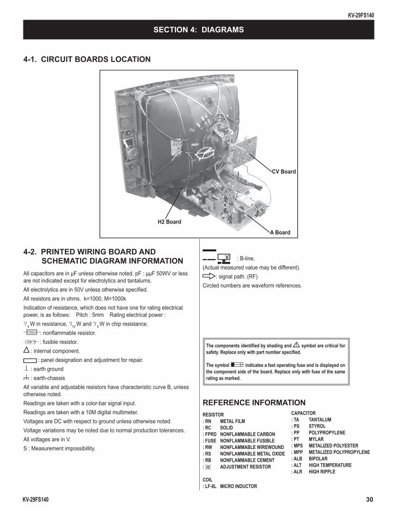
4-1. CIRCUIT BOARDS LOCATION
A Board
CV Board
H2 Board
SECTION 4: DIAGRAMS
4-2. PRINTED WIRING BOARD AND SCHEMATIC DIAGRAM INFORMATION
All capacitors are in µF unless otherwise noted. pF : µµF 50WV or less are not indicated except for electrolytics and tantalums.All electrolytics are in 50V unless otherwise specifi ed.All resistors are in ohms. k=1000, M=1000kIndication of resistance, which does not have one for rating electrical power, is as follows: Pitch : 5mm Rating electrical power : 1/ 4 W in resistance, 1/10 W and 1/ 8 W in chip resistance.
: nonfl ammable resistor. : fusible resistor.
: internal component. : panel designation and adjustment for repair.
: earth ground : earth-chassis
All variable and adjustable resistors have characteristic curve B, unless otherwise noted.Readings are taken with a color-bar signal input.Readings are taken with a 10M digital multimeter.Voltages are DC with respect to ground unless otherwise noted.Voltage variations may be noted due to normal production tolerances.All voltages are in V.S : Measurement impossibillity.
REFERENCE INFORMATION RESISTOR : RN METAL FILM: RC SOLID: FPRD NONFLAMMABLE CARBON: FUSE NONFLAMMABLE FUSIBLE: RW NONFLAMMABLE WIREWOUND: RS NONFLAMMABLE METAL OXIDE: RB NONFLAMMABLE CEMENT: ADJUSTMENT RESISTOR
COIL : LF-8L MICRO INDUCTOR
CAPACITOR: TA TANTALUM: PS STYROL: PP POLYPROPYLENE: PT MYLAR: MPS METALIZED POLYESTER: MPP METALIZED POLYPROPYLENE: ALB BIPOLAR: ALT HIGH TEMPERATURE: ALR HIGH RIPPLE
The components identifi ed by shading and ! symbol are critical for safety. Replace only with part number specifi ed.
The symbol indicates a fast operating fuse and is displayed on the component side of the board. Replace only with fuse of the same rating as marked.
: B+line.: B-line.
(Actual measured value may be different).: signal path. (RF)
Circled numbers are waveform references.
KV-29FS140
KV-29FS140 31
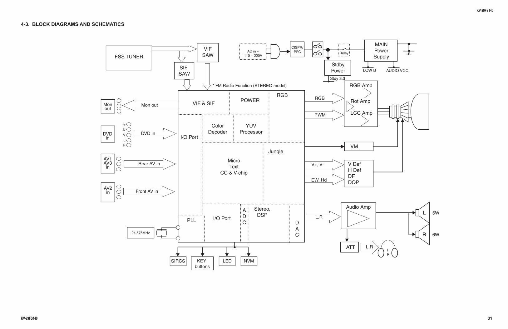
4-3. BLOCK DIAGRAMS AND SCHEMATICS
FIVWAS
FISWAS
NIAMrewoPylppuS
ybdtSrewoP
RENUT SSF
YU
VLR
zHM675.42
ni DVD
ni VA raeR
ni VA tnorF
tuo noM
)ledom OERETS( noitcnuF oidaR MF *
noMtuo
1VA3VA
ni
2VAni
DVDni
~ ni CAV022 ~ 011
/RPSICCFP yaleR
B WOL
3.3 ydtS
CCV OIDUA
LpmA oiduA
TTA
MVN
feD VfeD H
FDPQD
MV
pmA BGR
pmA toR
pmA CCL
W6
R W6
R,LHP
dH ,WE
R,L
-V ,+V
MWP
BGR
SCRIS YEKsnottub
LLP troP O/I
troP O/I
FIS & FIVREWOP
roloCredoceD
VUYrossecorP
elgnuJ
BGR
ADC D
AC
,oeretSPSD
orciMtxeT
pihc-V & CC
DEL
B+
KV-29FS140
KV-29FS140 32
1 | 2 | 3 | 4 | 5 | 6 | 7 | 8 | 9 | 10 | 11 | 12 | 13 | 14 | 15 | 16 | 17 | 18 | 1
A
—
B
—
C
—
D
—
E
—
F
—
G
—
H
—
I
—
J
—
K
—
L
—
M
—
N
—
O
—
P
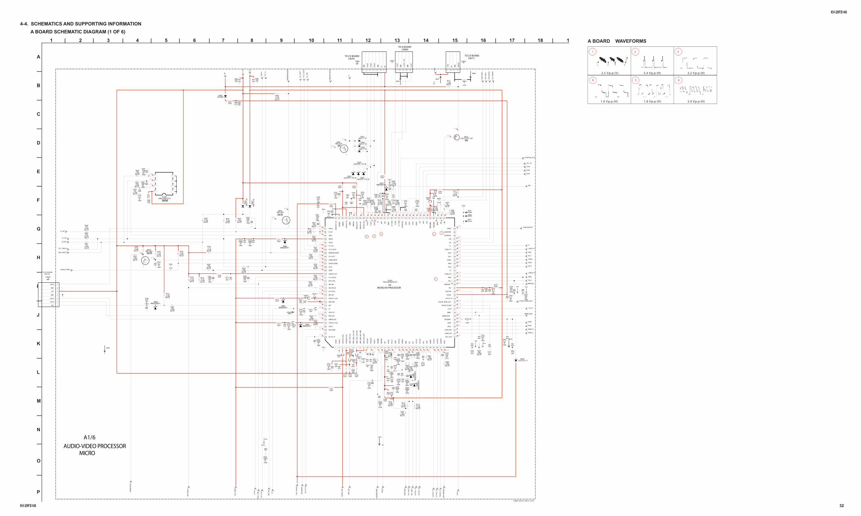
A BOARD SCHEMATIC DIAGRAM (1 OF 6)4-4. SCHEMATICS AND SUPPORTING INFORMATION
C032XX
1/10WRN-CP
4 . 7 kR001
EWD
-DEF
L
IIS
_O
UT
1
10uHL006
MM3Z3V3T1D08410uH
L013
1608
10V0 . 2 2
B
C022
1 2 3 4
4PCN003
135V
NC
GN
D
VM O
UT
B_INT
INL1
50V2 . 2
C073
OC
P-P
RO
TEC
T
VG
UA
RD-D
EFL
CVBS3
1/10WRN-CP
2 . 2 kR338
1608
50V100p
CH
C091 10uHL009
1608
50V100p
CH
C021
10V470
C006
W053
1608
25V0 . 0 1
B
C018
MA111-TXD058
2SA1235TP-1EFQ010
1608
16V0 . 2 2
B
C042
SDA
-0
25V47
C026
0MHzX001
5V
10uHL033
SIF
IN1
-IF
+B
_2
1608
50V1000p
B
C081
1608
50V4700p
B
C041
RN-CP
12kR306
1/10W
1608
16V0 . 1
B
C054
2012
16V2 . 2
F
C023
W082
0uHFB008
87
65 4
32
1
24WC16WI-TE13IC003
1/10WRN-CP
4 . 7 kR394
1/10WRN-CP
470R337
1608
25V0.022
B
C053
1/10WRN-CP
4 . 7 kR317
1/10WRN-CP
100R386
16V100
C004
1608
16V0 . 2 2
B
C0481/10WRN-CP
68kR379
50V2 . 2
C311
1608
16V0 . 2 2
B
C321
TP02
MM
3Z5V
6ST1
D06
4
1/10WRN-CP
1 . 5 kR015
16V470
C002
W079
S2
1/10WRN-CP
4 . 7 kR023
1/10WRN-CP
100R048
LSL-
AU
DIO
SCL_CN010
W059
1608
50V470p
CH
C301
1/10WRN-CP
470R011
1/10WRN-CP
100R030
CHIP
0JR801
1608
16V0 . 1
B
C028
SUIN
10V470
C029
VIF
IN1
-IF
MM3Z5V6ST1D068
1/10WRN-CP
4 . 7 kR003
1608
16V0 . 2 2
B
C025
1608
50V1000p
B
C031
1608
50V1000p
B
C052
10uHL011
W034
KRC102SQ018
IIS
_W
S
10uHL003
3.3
V
OUTR
1608
25V0.022
B
C049
0uHFB010
1608
50V1000p
B
C080
16V100
C056
W030
1/10WRN-CP
220R097
M-S
YS
-IF
1608
50V47p
CH
C319
MM3Z3V3T1D083
STBY
_SW
CVBS/PIPOUT
MA
111-
TXD
003
16V100
C304
AG
C-M
UTE
CHIP
0R324
1608
25V6800p
B
C046
1/10WRN-CP
100R026
ABL
1/10WRN-CP
100R004
1/10WRN-CP
100R025
1608
16V0 . 2 2
B
C335
C1
1608
16V0 . 1
B
C0691608
25V0 . 1
B
C333
1608
50V470p
CH
C010
1/10WRN-CP
100R022
0uHFB011
1/10WRN-CP
4 . 7 kR314
1608
50V1000p
B
C322
16V2 . 2
C044
F2012
KARA_L
W063
SVIN
1608
50VCH
C034XX
1608
50V100p
CH
C090
DG
C-R
ELA
Y
INL3
1/10WRN-CP
2 . 2 kR012
1/10WRN-CP
2.2kR056
P L L I F
TP03
1608
50V100p
CH
C003
INR3
LSR
-AU
DIO
1608
50V47p
CH
C320
1/10WRN-CP
1 . 5 kR377
W0761/10WRN-CP
100R384
1/10WRN-CP
100R046
1/10WRN-CP
100R002
1.8
V_
MA
IN
2S
IF
OUTL
16V100
C036
16V220
C317
1/10WRN-CP
100R045
1/10WRN-CP
220R096
1 2 3 4 5 6 7 8 9 10 11 12 13 14 15 16 17 18 19 20 21 22 23 24 25 26 27 28 29 30 31 32
33
34
35
36
37
38
39
40
41
42
43
44
45
46
47
48
49
50
51
52
53
54
55
56
57
58
59
60
61
62
63
64
6566676869707172737475767778798081828384858687888990919293949596
97
98
99
100
101
102
103
104
105
106
107
108
109
110
111
112
113
114
115
116
117
118
119
120
121
122
123
124
125
126
127
128
TDA12019H/N1E7FIC001
TMP
VSS
P2
VSS
C4
VD
DC
4(1
.8V
)
VD
DA
3(3
.3V
)
VR
EF_P
OS_
LSL
VRE
F_N
EG_L
SL+
LSR
VRE
F_PO
S_LS
R+H
PL
vREF
_NEG
_HPL
+H
PR
VRE
F_PO
S_H
PR
XTA
LIN
XTA
LOU
T
VSS
A1
VGU
ARD
DEC
DIG
VP1
PH2L
F
PH1L
F
GN
D1
SEC
PLL
DEC
BG
EWD
VD
-
VD+
VIF
IN1
VIF
IN2
VSC
IRE
F
GN
DIF
SIF
IN1
SIF
IN2
AGCO
UT
EHT0
AVL/2SIF
KARA LIN
KARA RIN
OUTL
OUTR
DECSDEM
MONO_OUTL
GND2
PLLIF
SIFAGC/SCART
IFVO/IF_MON_OUT
INTC0-IF
VCC8V
AGC2SIF
VP2
MON-OUT
INL2
INR2
CVBS2/Y2
C2
INL3
INR3
CVBS3
INL1
INR1
CVBS1/Y1
C1
LSL
LSR
SCARTHPL
SCARTHPR
CVBS0
VMAFC
HO
UT
VSSC
OM
B
VDD
COM
BVIN
UIN
YIN
YSYN
C
YOU
T
UO
UT
VOU
T
SCA
RTFB
L
R-Y
/RIN
Y/G
IN
B-Y
/BIN
GN
D3
VP3
ABLIK
R O
UT
G O
UT
B O
UT
VD
DA
(3.3
V)
VREF
AD
_NE
VREF
AD
_PO
VREF
AD
GN
DA
VD
DA
(1.8
)
VDD
A2
VSSA
DC
VD
DA
DC
(1.8
)
SIRCS
B INT
SDA1
VDDC2
VSSC2
I I S W S
IIS CLOCK
MOMUTE-AUDIO
IIS OUT1
AUDIO MUTE
AUDIO STDBY
SCL0
SDA0
VDDP(3.3V)
S1/VC(GA)
ROT CTRL
ROT SW
DGC RELAY
AFT(PIP)
MIC SW
VDDC1(1.8V)
DECV1V8
KEY
S2
VSSC1/P
RED LED
GREEN LED
VDDC3(1.8V)
VSSC3
AGC-MUTE
M-SYS-IF
1/10WRN-CP
1kR059
VDD
C4_
CA
P
1/10WRN-CP
100R029
MA111-TXD057
1/10WRN-CP
100R038
1/10WRN-CP
12kR044
W066
MONO_OUTL
1/10WRN-CP
100R393
10uHL012
1/10WRN-CP
100R380
1608
50V1000p
B
C312
TU
AG
C-I
F
1608
25V0 . 0 1
B
C328
VD
--D
EF
L
1/10WRN-CP
100R060
10uHL007
2012
50VCH
C3230 . 0 1
16V100
C005
1 2 3 4 5
5PCN007
Y O
UT
GN
D
U O
UT
/ F
B
GN
D
V O
UT
AFC
-DEF
L
1608
50V1000p
B
C313
1608
50V1000p
B
C089
1/10WRN-CP
220R099
1608
50V100p
CH
C001
1608
16V0 . 1
B
C020
1
2
3
4
5
6
7
WHT7P
CN3101
KEY
LED R
LED G
GND
VCC
GND
SIRCS
SC
L-0
W031
1608
10V0 . 4 7
B
C316
16V100
C013
B_CLK
W078
RN-CP
R3166 . 8 k
1/10W
MIC
_SW
1/10WRN-CP
100R014
10uHL036
PG102RD066
10uHL032
50V3 . 3
C065
10uHL010
RO
T_C
TRL
1/10WRN-CP
470R364
PWR
-OFF
-MU
TE
W011
CHIP
0R058
10uHL005
SDA_CN010
10uHL035
0uHFB009
AF
T-P
IP
1/10WRN-CP
100R039
MON-OUT
1/10WRN-CP
2 . 2 kR042
SCARTFBL/A16
1608
25V0 . 0 1
B
C308
INL2
IIS
_C
LO
CK
MM
3Z5V
6ST1
D06
5
1608
50V1000p
B
C325
1608
16V0 . 1
B
C092
CVBS2/Y2
UDZSTE-179.1BD025
16V100
C303
50V4 . 7
C302
SYIN
VIF
IN2
-IF
CVBS1/Y1
SEL_IN
1 2 3 4 5 6 7
WHT7P
CN004
GN
D
B O
UT
G O
UT
R O
UT
GN
D
IK 9V
0uHFB007
A
0uHFB006
CHIP0
JR099
UDZSTE-179.1BD023
9V
1/10WRN-CP
39kR051
10uHL008
1/10WRN-CP
R020100
1608
16V0 . 1
B
C318
W033
1/10WRN-CP
100kR395
1/10WRN-CP
4 . 7 kR399
1608
16V0 . 1
B
C038
1/10WRN-CP
4 . 7 kR336
INR1
HO
UT-
DEF
L
47uHL004
VD
+-D
EFL
IFVO/IF_MON_OUT
MM3Z9V1ST1D075
PH
2LF
W077
W010
UDZSTE-179.1BD024
1608
50V1000p
B
C332
1/10WRN-CP
100R024
KARA_R
1/10WRN-CP
100R339
1.8
V_
AU
DIO
S1
/VC
CHIP0
JR1011
INR2
1/10WRN-CP
100R341
250V0 . 1 5C055
SIF
IN2
-IF
1608
16V0 . 2 2
B
C030
B_DAT
MO
MU
TE-A
UD
IO
50V10
C050
CHIP
JR1012&0
1SS133T-77D074
50V2 . 2
C064
1/10WRN-CP
4 . 7 kR315
AUDIO-STDBY
1/10WRN-CP
100R385
10uHL031 TP04
KRC102SQ001
1/10WRN-CP
100R323
MA111-TXD059
1/10WRN-CP
10kR010
10V1
C037
B1608
1608
16V0 . 1
B
C063
0uHFB005 1608
50V2200p
B
C329
1/10WRN-CP
100R041
MM3Z3V3T1D082
KRC102SQ016
W075
MA
111-
TXD
002
50V22
C024
1/10WRN-CP
2 . 2 kR340
AU
DIO
-MU
TE
1/10WRN-CP
4 . 7 kR320
+B
_2
0 . 0
3 . 3
0.1
1.3
2 . 0
1.3
2 . 2
2 . 4
1.6
2 . 6
2.0
0.1
3 . 3
3 . 3
2 . 3
MUTE
0 . 0
2 . 4
0.5
3 . 5
1.6
2 . 4
6
0.1
A1/6
1 . 8
0 . 0
2 . 2
2 . 2
VM
2.0
1.9
0 . 0
0 . 7
3 . 3
0 . 0
2 . 4
0.1
1.3
5
1.3
MICRO
1 . 6
3 . 5
1 . 9
MICRO/AV PROCESSOR
2.4
2.3
0 . 0
3 . 3
1 . 4
NVM
2 . 8
0.1
2.0
1
1.3
AUDIO-VIDEO PROCESSOR
2 . 2
2 . 3
3 . 6
3 . 5
1.9 0 . 6
2.3
1 . 8
3 . 5
CN4103
3 . 3
2 . 9
0 . 0
0 . 3MUTE 1.6
3.2
2 . 2
0 . 1
3
3 . 6
1.9
2 . 2
2.3
2.6
3 . 3
0 . 6
4 . 9
1.8
0.1
1.4
2 . 0
2
2 . 2
4.3
SW
2.0
2.3
0 . 0
3 . 3
0 . 0
2.9
1.3
1.6
1 . 8
2 . 0
3.5
2 . 0
1.6
2.3
3 . 5
2 . 2
3 . 2
4
TO CV BOARDCN711CN701
TO CV BOARD
CN905TO A BOARD
TO H2 BOARD
9-883-705-01<BX1L>A-P1
5 64
1.6 V p-p (H) 1.8 V p-p (H) 2.0 V p-p (H)
321
2.5 V p-p (V ) 5.4 V p-p (H) 3.2 V p-p (H)
A BOARD WAVEFORMS
KV-29FS140
KV-29FS140 33
1 | 2 | 3 | 4 | 5 | 6 | 7 | 8 | 9 | 10 | 11 | 12 | 13 | 14 | 15 | 16 | 17 | 18 |
A
—
B
—
C
—
D
—
E
—
F
—
G
—
H
—
I
—
J
—
K
—
L
—
M
—
N
—
O
—
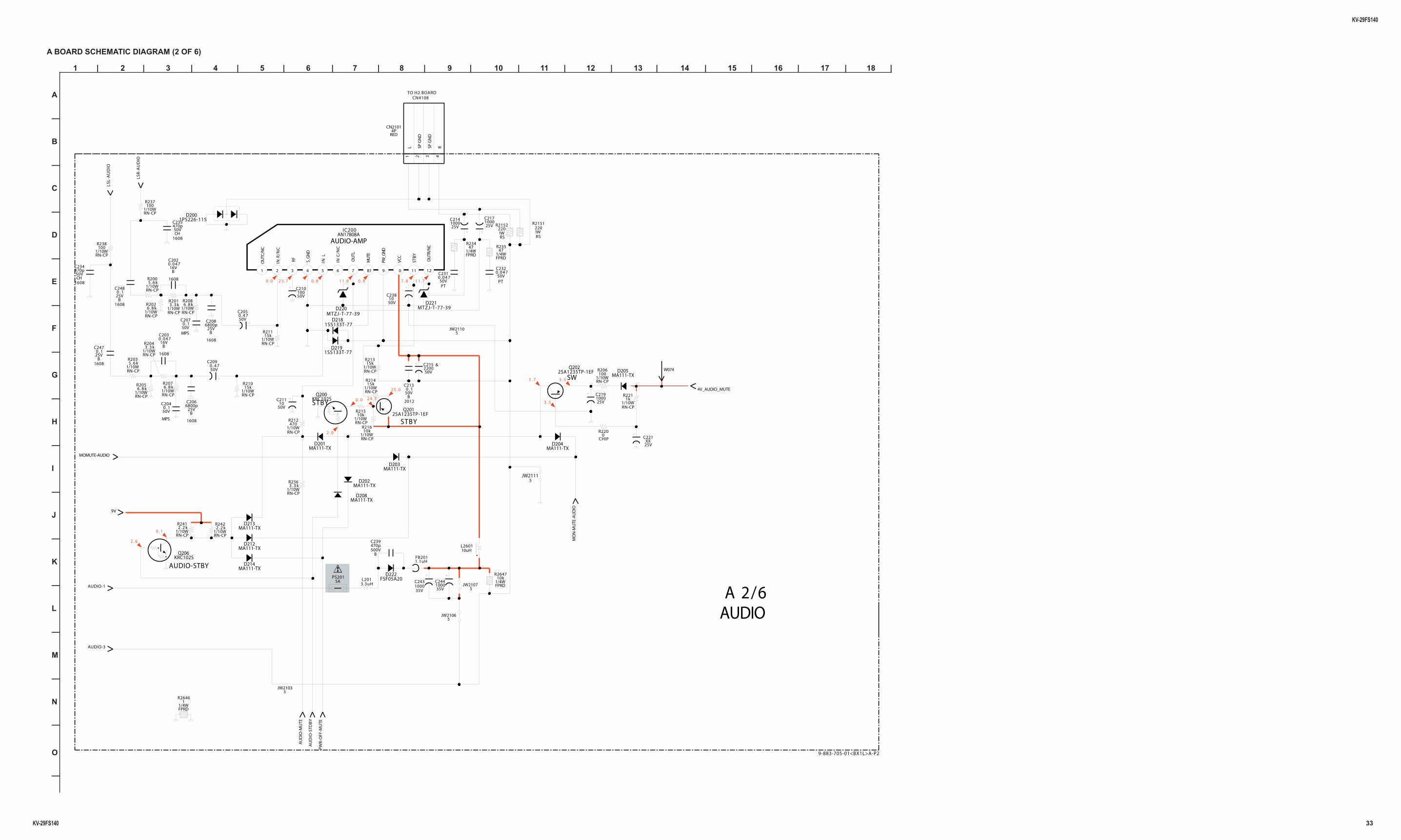
A BOARD SCHEMATIC DIAGRAM (2 OF 6)
R201
RN-CP1/10W
3 . 3 k
C209
50V0 . 4 7
MO
N-M
UTE
-AU
DIO
RN-CP
R212
1/10W470
5JW2110
1/10WRN-CP
R206100
MTZJ-T-77-39D220
9V
1608
50VCH
C234470p
50V
C23810
2SA1235TP-1EFQ202
KRC102SQ200
1PS226-115D200
C239
500VB
470p
35V
C2441000
PWR
-OFF
-MU
TE
C211
50V10
CHIP
R2200
MA111-TXD204
50VPT
C2320.047
R211
1/10WRN-CP
15k
1/10WRN-CP
R2422 . 2 k
1/10WRN-CP
R21315k
MA111-TXD208
1/10WRN-CP
R21610k
R208
1/10WRN-CP
6 . 8 k
2012
50VB
C2130 . 1
PS2015A
1/4W
R235
FPRD
47
C217
25V1000
LSR
-AU
DIO
MTZJ-T-77-39D221
MOMUTE-AUDIO
C247
25VB
1608
0 . 1
1W
R2151
RS
220
2SA1235TP-1EFQ201
MA111-TXD213
1SS133T-77D218
KRC102SQ206
C248
25VB
1608
0 . 1
R234
1/4WFPRD
47
C206
25VB
1608
6800p1 2 3 4
RED4P
CN2101
L SPG
ND
SPG
ND
R
FSF05A20D222
JW21115
C243
35V1000
C208
25VB
1608
6800pC207
50V0 . 1
MPS
MA111-TXD202
R237
1/10WRN-CP
100
AU
DIO
-MU
TE
R236
1/10WRN-CP
3 . 3 k
R202
1/10WRN-CP
6 . 8 k
C203
16VB
1608
0.047
AUDIO-1
C202
16VB
1608
0.047
5JW2103
R200
RN-CP1/10W
5 . 6 k
R203
RN-CP1/10W
5 . 6 k
FB2011.1uH
MA111-TXD205
MA111-TXD212
R204
RN-CP1/10W
3 . 3 k
25V
C2191000
R205
1/10WRN-CP
6 . 8 k
L260110uH
AUDIO-3
1/10WRN-CP
R21510k
1/4WFPRD
1R2646
R238
1/10WRN-CP
100
C214
25V1000
C205
50V0 . 4 7
1W
R2152
RS
220
C204
50V0 . 1
MPS
MA111-TXD203
L2013.3uH
5JW2107
W074
1/10WRN-CP
R2211k
4V_AUDIO_MUTE
81 2 3 4 9765 1 0 11 12
IC200AN17808A
OU
TC/N
C
INR
/NC
RF
S_G
ND
INL
INC
/NC
OU
TL
MU
TE
PW_G
ND
VCC
STB
Y
OU
TR/N
C
C221XX
25V
C231
50VPT
0.047
1/10WRN-CP
R21415kR210
1/10WRN-CP
15k
1SS133T-77D219
R207
1/10WRN-CP
6 . 8 k
50V
C210100
AU
DIO
-STD
BY
5JW2106
C235
50VCH
1608
470p
C215
50V2200
&
MA111-TXD214
1/4WFPRD
R264710k
1/10WRN-CP
R2412 . 2 k
LSL-
AU
DIO
MA111-TXD201
2 5 . 0
7 . 8
AUDIO
3 . 5
A 2/6
2 . 0
1 1 . 8
0 . 1
STBY
2 . 6
1 . 7
0 . 0
SW
0 . 0
0 . 0
AUDIO-AMP
AUDIO-STBY
2 4 . 3
1 1 . 70 . 9
3 . 5
STBY
2 3 . 7
TO H2 BOARDCN4108
9-883-705-01<BX1L>A-P2
KV-29FS140
KV-29FS140 34
1 | 2 | 3 | 4 | 5 | 6 | 7 | 8 | 9 | 10 | 11 | 12 | 13 | 14 | 15 | 16 | 17 | 18 | 19 | 20 | 21 | 22 | 23 | 24 | 25 | 26 | 27 | 28 |
A
—
B
—
C
—
D
—
E
—
F
—
G
—
H
—
I
—
J
—
K
—
L
—
M
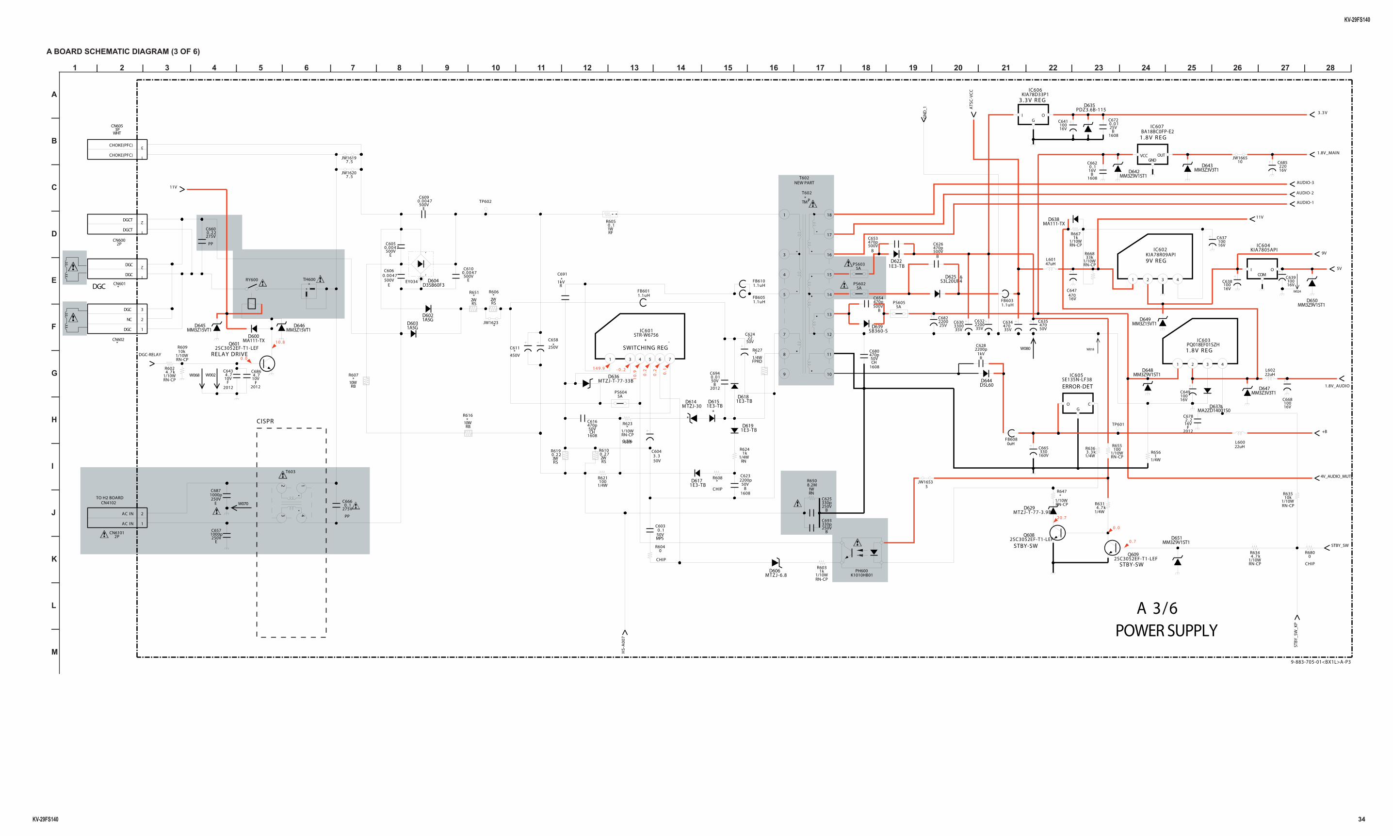
A BOARD SCHEMATIC DIAGRAM (3 OF 6)
250V
C658 *
1/4W3 . 3 kR636
4V_AUDIO_MUTE
1608
50V470p
CH
C616
1
3
3PCN605
WHT
CHOKE(PFC)
CHOKE(PFC)
COG
SE135N-LF38IC605
1/10WRN-CP
4 . 7 kR634
HS-
A0
07
1.8V_MAIN
500V470p
B
C653
TP602
1/4W4 . 7 k
R631
CHIP
*R608
2012
16V2 . 2
F
C678
FB6051.1uH
K1010HB01PH600
1E3-TBD618
16V100
C641
MA2ZD14001S0D637&
250VE
C6871000p
1/10WRN-CP
33kR668
1 3 4 5 6 7
STR-W6756 *
IC601 SB360-SD639
JW16535
MM3Z15VT1D645
50V470
C635
1/10WRN-CP
*R647
160V330
C665
9V
AUDIO-3
10JW1665
50V3 . 3
C604
AUDIO-2
1/10WRN-CP
100R655
2SC3052EF-T1-LEFQ609
RN-CP
1kR603
1/10W
1/4W1
R656
1608
50V470p
CH
C680
2WRS
R606 *
MTZJ-T-77-33BD636
1W8.2MR650
RN
FB6011.1uH
W06810V4 . 7
C643
F2012
1/4W*
R627
FPRD
1WRF
0 . 1R605
MM3Z15VT1D646
‘
‘
D3SB60F3D604
W018
1A5GD602
10V4 . 7
C686
F2012
22uHL600
50V22
C624
25V2200C682
DGC-RELAY
W002
MA111-TXD600
250V330p
B
C693
EY034
10WRB
R607*
MA111-TXD638
W080
1.1uHFB603
1kV2200pC628
R
MTZJ-6.8D606
1A5GD603
500V470p
B
C626
35V3300C630
W024
1/10WRN-CP
1kR667
TH600 *
+B
2SC3052EF-T1-LEFQ608
500V0.0047
E
C609
JW1623
2WRS
R651 *
TP601
MM3Z9V1ST1D651
MM3Z3V3T1D647 1.8V_AUDIO
1/10WRN-CP
10kR609
1 2 3 4
KIA78R09APIIC602
1E3-TBD619
500V0.0047
E
C605
500V0.0047
E
C610
MM3Z3V3T1D643
2WRS
0 . 2 7R610
1/10WRN-CP
10kR635
5V
16V100C649
16V100
C6391kV
R
C691 *
1E3-TBD622
47uHL601
MM3Z9V1ST1D648
16V100
C668
35V2200C632
STB
Y_S
W_K
P
16V100
C638
22uHL602
250V1000p
E
C657
AUDIO-1
5APS604
11V
1
2
2PCN6101
AC IN
AC IN
3WRS
0 . 2 2R619
7 . 5JW1620
RY600
275V
PP
0 . 1C666
D5L60D644
MM3Z9V1ST1D642
CHIP
0R604
5APS605
10WRB
*R616
GN
D_1
I OCOM
KIA7805APIIC604
35V470C634
1608
25V0 . 0 1
B
C672
1E3-TBD617
1
2
2PCN600
DGCT
DGCT
2SC3052EF-T1-LEFQ601
STBY_SW
500V0.0047
E
C606
1/4WRN
1kR624
MM3Z15VT1D649
I OG
KIA78D33P1IC606
500V470p
B
C654
CHIP
0R680
1608
16V0 . 1
B
C662
16V220
C685
PDZ3.6B-115D635
7
3 16
17
12
14
13
181
15
8
10
11
5
9
4
T602 * TMP
50V0 . 1
C603
MPS
ATS
C-V
CC
1
2
3
*CN602
DGC
NC
DGC
0uHFB608
16V100
C637
1 2 3 4
PQ018EF01SZHIC603
FB6101.1uH
MTZJ-T-77-3.9BD629
2012
50VB
C6940 . 0 1
275V
PP
0 . 2 2C660
1608
50V2200p
B
C623
16V470
C647
5APS603
123 4
T603
W070
7 . 5JW1619
250V330p
B
C625
S3L20UF4D625 &
11V
MM3Z9V1ST1D650
1/4W100
R621
5APS602
1
2
*CN601
DGC
DGC
VCCGND
OUT
BA18BC0FP-E2IC607
3 . 3 V
1/10WRN-CP
4 . 7 kR602
450V
C611 *
1608
1/10WRN-CP
0.5%
R623 *
1E3-TB *
D615M TZJ-30
*
D614
3 . 3 V R E G
STBY-SW
149.9
DGC
9V REG
ERROR-DET
- 0 . 2
1 . 8 V R E G
0 . 0
0 . 7
SWITCHING REG.
1 . 8 V R E G
2 0 . 7
STBY-SW
CISPR
0.1
0.2
A 3/6
1 0 . 8
10
.9 0.2
0 . 0
NEW PART
POWER SUPPLY
RELAY DRIVE
T602
TO H2 BOARDCN4102
9-883-705-01<BX1L>A-P3
*
KV-29FS140
KV-29FS140 35
1 | 2 | 3 | 4 | 5 | 6 | 7 | 8 | 9 | 10 | 11 | 12 | 13 | 14 | 15 | 16 | 17 | 18 | 19 | 20 | 21 | 22 | 23 | 24 | 25 | 26 | 27 | 28 |
A
—
B
—
C
—
D
—
E
—
F
—
G
—
H
—
I
—
J
—
K
—
L
—
M
—
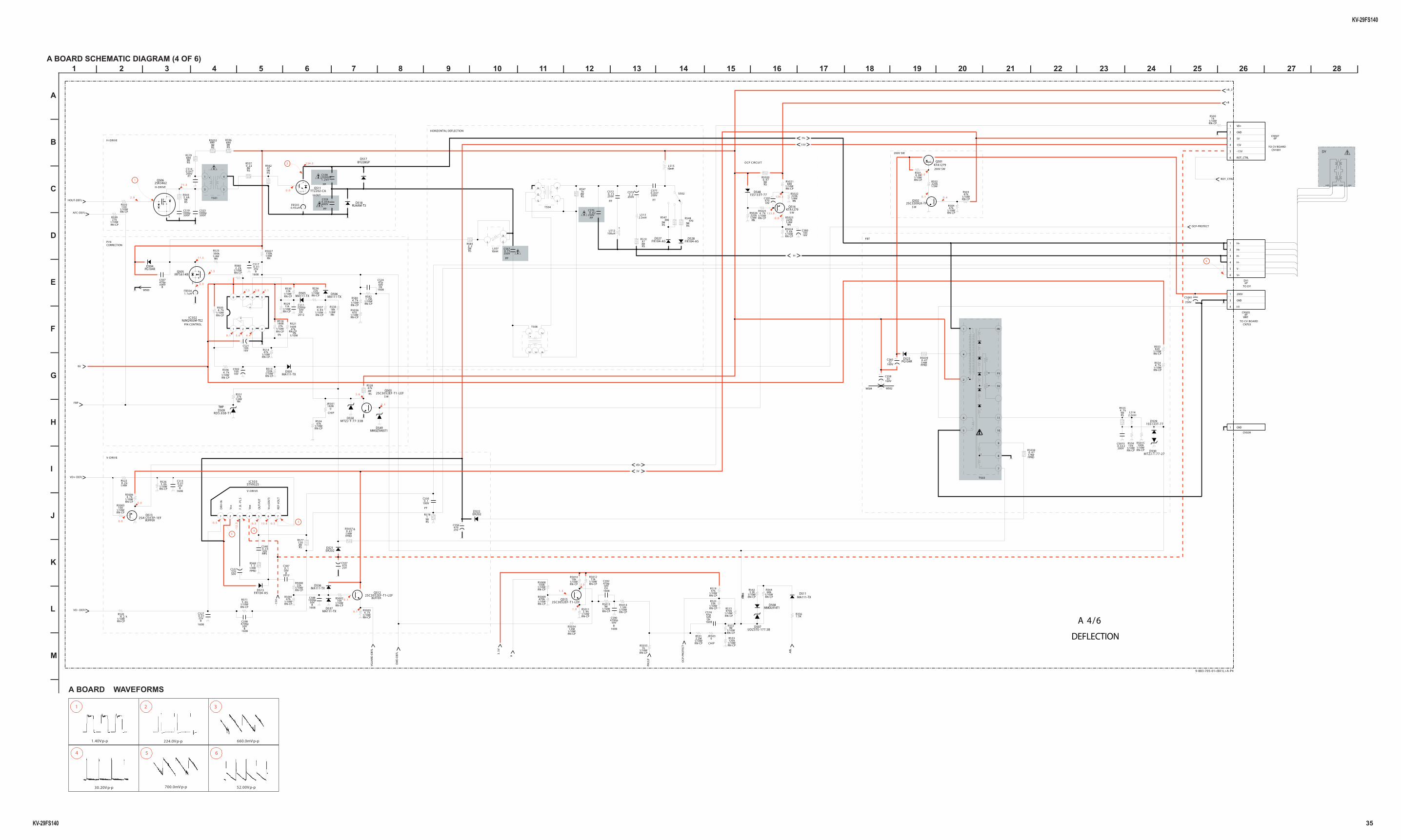
A BOARD SCHEMATIC DIAGRAM (4 OF 6)
1WRS
5 . 6 kR543
8 7 6 5
4321
NJM2903M-TE2IC502
1608
50V4700p
B
C598
1/10WRN-CP
1kR5035
MTZJ-T-77-33BD550
D522ER202
S
2SK3462Q506
1.1uHFB504
MA111-TXD506
1/10W1k
R500
RN-CP
R55127k
1/4WRN
5V
D523PG104R
MA111-TXD511
R5544 . 7 k
1/10WRN-CP
1/10WRN-CP
10kR5010
160V22
C565
D518RU4AM-T3
1/10WRN-CP
2.2MR531
R5821.2M,
1/10WRN-CP
FR104-A5D527
1/10WRN-CP
47kR519
-15
V
OCP-PROTECT
R553820
RN-CP1/10W
1/10WRN-CP
10kR5002
MA111-TXD537
1/10WRN-CP
100R5005
D5291SS133T-77
1/10WRN-CP
470R5036
C5130 . 0 125V
B1608
FBP
1/10WRN-CP
4 . 7 kR5006
AFC-DEFL
2WRS
1kR597
1/10WRN-CP
4 . 7 kR5003
C5390.056400V
PP
1/10WRN-CP
47kR5001
2SA1235TP-1EFQ513
C5700 . 8 2
250VPP
C507470p500V
B
R5021680
1/10WRN-CP
D521ER202
1 2435
T508
VD--DEFL
HOUT-DEFL
R5208 . 2 k
1/10WRN-CP
1608
50V4700p
B
C590
2WRS
47kR528
50V220
C537
1608
50VCH
C51847p
1/4W220k
R5023
RN
1
3
4
WHT4P
CN505
200V
GND
H1
+B_2
C58010016V
1/10WRN-CP
47kR504
R525390k1/4W
RN
200V0.022C5073
S
IRFS614BQ505
KTA1279Q501
50V0 . 3 3C540
MPS
100V
PT
0 . 1C550
2SC3052EF-T1-LEFQ512
VD+-DEFL
R50326803WRS
1
2
3
4
5
6
6PCN507
VD+
GND
5V
15V
-15V
ROT_CTRL
1/10WRN-CP
47kR503
1/10WRN-CP
4 . 7 kR505
160V33
C558
C5720 . 1 5250V
PP
1/10WRN-CP
68kR544
1/10WRN-CP
100kR5008
1/10WRN-CP
4 . 7 kR506
MM3Z5V6ST1D549
R579
3WRS
680
MA111-TXD505
KTA1279Q516
1
CN509
GND
200VPT
0.047C514
L51510mH
3WRS
0 . 4 7R5020
R5554 . 7 k1WRS
+B
L512100uH
1/10W100k
R5015
RN-CP
1/4WRN
18kR538
1/4WFPRD
0 . 4 7R5037 &
1/10WRN-CP
R513220k
2W2 . 2
R585
RS
25V470
C556
D517BY228GP
1/10WRN-CP
R524
9V
R5781
1WRS
1/10WRN-CP
1MR5013
R5228 . 2 k
1/4W
3WRS
470R548
50V0 . 1
C587
B2012
R50245 . 6 k
1/10WRN-CP
1/10WRN-CP
120kR533
D530MTZJ-T-77-27
1 3
4
L50710mH
R510473WRS
25V470
C557
L5132.2mH
1/10WRN-CP
27kR599
2WRS
120R577
R5715 . 6 k
1/10WRN-CP
1/2W220kR502
1/10WRN-CP
1 0 0R535
1/10WRN-CP
470kR515
ROT_CTRL
MA111-TXD536
1608
1/10WRN-CP
R518
5%
27k
H+
2SC3209LK-TPQ502
W503
1/10WRN-CP
6 . 8 kR537
H-
EWD
-DEF
L
1608
50V470p
CH
C592
1/4WFPRD
0 . 4 7R5039
W502
16V100
C521
1/10WRN-CP
22kR530
C5231000p500V
VG
UA
RD-D
EFL
MA111-TXD501
1/10WRN-CP
4 . 7 kR5025
C5742 . 2
250VS502
16V
C502100
CHIP
0JR503
1/4W220k
R5026
RN
Q511TT2202-CA
2012
50V2200p
CH
C511
R5027150k1/4W
RN
1/10WRN-CP
1.0MR5034
1608
CHIP
JR501
0
1/10WRN-CP
1MR532
1
3
4
5
T501
500V1000pC519
PG104RD504
1608
50V47p
CH
C524
250V1
C5001
1
24
3
5
T504
1608
25V0 . 0 1
B
C517
1/10WRN-CP
470kR5009
1/4WFPRD
0 . 4 7R5038
R5022220k1/4W
RN
W504
3.3
V
1/10WRN-CP
15kR529
1/10WRN-CP
33kR523
1/10WRN-CP
1.5MR5014
R5966803WRS
1W47
R562
RS
MMDL914T1D508
1608
50V1000p
B
C588
2SC3052EF-T1-LEFQ515
R5265 . 6 k
1/10WRN-CP
1608
1/10W
RN-CP
R521
5%
47k
16
08
RN-CP
R542
1/10W
5%
3.3K
5
6
SV
9
10
HV
2
4
1
7
8
11
FV
T503
2SC3052EF-T1-LEFQ503
1/4WFPRD
1 . 5R568
UDZSTE-177.5BD507
10V470
C5971SS133T-77
D548
0.45uHFB503
VD+
1
2
3
4
5
6
DY16P
H+
H+
H-
H-
V-
V+
1/10WRN-CP
22kR536
1/10WRN-CP
6 . 8 kR501
D509RD5.6SB-T1
TMP
R514
1/10WRN-CP
47k
1 2 3 4 5 6 7
STV9325IC503
DR
V-I
N
Vcc
F.B
.-P
LS
Vee
OU
T-PU
T
Vcc
(OU
T)
REF
-VO
LT
OC
P-P
RO
TEC
T
C5670 . 7 5250V
PP
C53820000P1.2kV
PP
2WRS
390R547
R557
2WRS
0 . 2 2
R5602 . 2 k
1/10WRN-CP
PH
2LF
AB
L
R5561 0 k
1/10WRN-CP
FR104-A5D513
1.5KR356
L5142.2mH
1/10WRN-CP
15kR5012
15V
A
C5770.047200V
PT
25V0 . 0 1
B
C527
1608
1/10WRN-CP
22kR5000
1/10WRN-CP
3 . 9 kR5011
FR104-A5D528
R5804 . 7 k
1/10WRN-CP
0 . 0
0 . 5
TO CV BOARD
6
-
5 . 6
P I N
1 3 . 6
4 . 4
DEFLECTION
200V SW
4
CORRECTION
0 . 1
200V SW
0 . 3
2 . 9
CN703
V-DRIVE
-12
.3
H-DRIVE
0 . 5
+
134.3
0 . 0
BUFFER
FBT
0 . 1
HORIZONTAL DEFLECTION
3
4 . 1
0 . 0
BUFFER
H-DRIVE
0 . 0
+
3 . 8
H-OUT
S W
7 . 5
0 . 40 . 1
V-DRIVE
1
133.9
TO DY
1 7 . 5
TO CV BOARD
0 . 0
1 . 5
7 . 5
S W
PIN CONTROL
134.3
CN1801
2 . 0
2
1 . 0
OCP CIRCUIT
5 . 6
5
0 . 1
S W
-
7 1 . 3
A 4/6
0 . 0
0 . 1
9-883-705-01<BX1L>A-P4
DY
H.DY H.DY V.DY V.DY
47K
54
321
A BOARD WAVEFORMS
1.40V p-p 224.0V p-p 660.0mV p-p
700.0mV p-p30.20V p-p 52.00V p-p
6
KV-29FS140
KV-29FS140 36
1 | 2 | 3 | 4 | 5 | 6 | 7 | 8 | 9 | 10 | 11 | 12 | 13 | 14 | 15 | 16 | 17 | 18 | 19 | 20
A
—
B
—
C
—
D
—
E
—
F
—
G
—
H
—
I
—
J
—
K
—
L
—
M
—
N
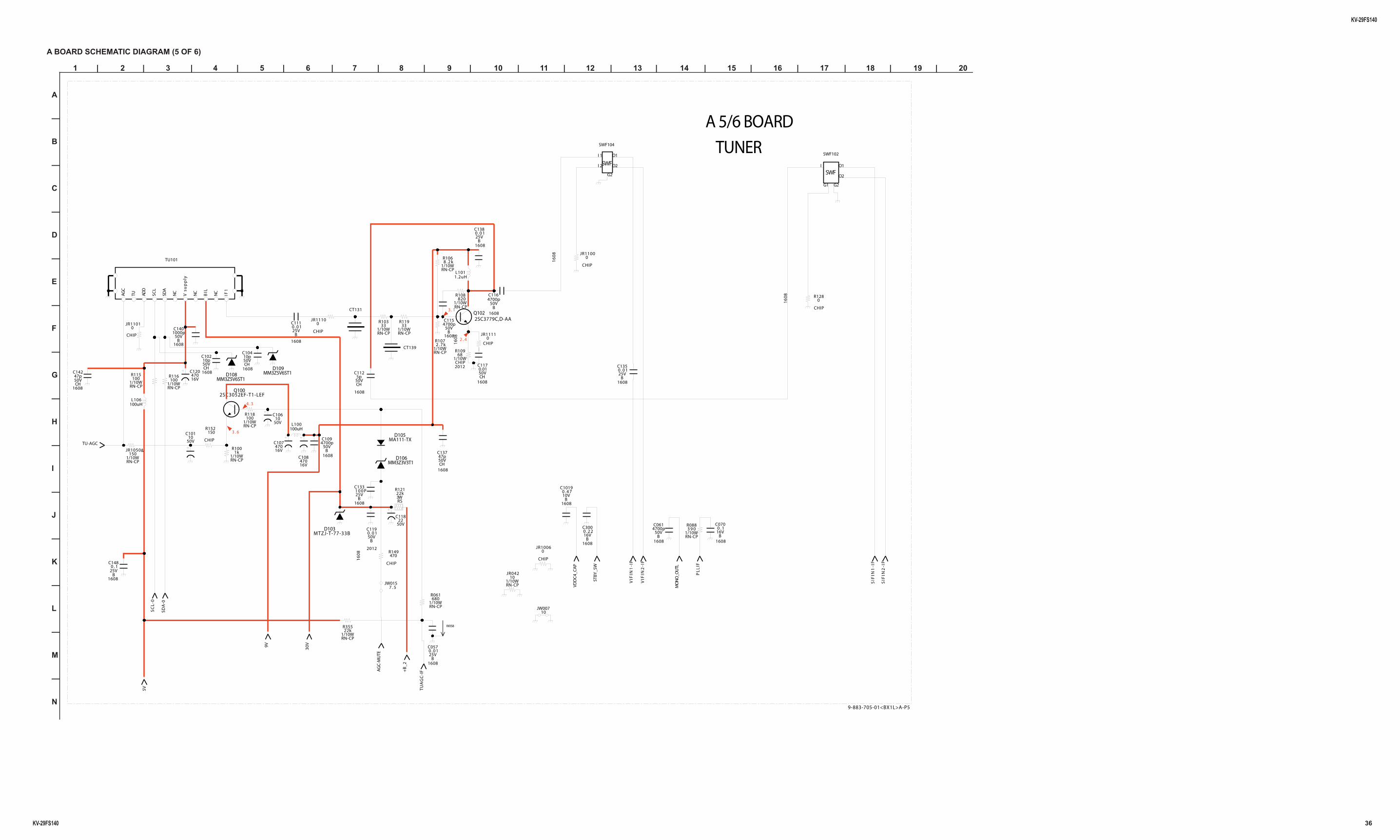
A BOARD SCHEMATIC DIAGRAM (5 OF 6)
VIF
IN1
-IF
1608
25VB
C1480 . 1
MM3Z5V6ST1D109
50V10
C106
3WRS
22kR121
16V470
C1201608
50V10p
CH
C104
AG
C
ADD
SCL
SDA
V s
up
ply
BIL
IF1
TU NC
NC
NC
TU101
C0614700p
50VB
1608
SIF
IN1
-IF
W058
16V470
C108
1/10WRN-CP
10JR042
SIF
IN2
-IF
Q1002SC3052EF-T1-LEF
1608
10V0 . 4 7
B
C1019C133
25VB
1608
1 0 0 P
JW00710
JR1111
16
08
CHIP0
AG
C-M
UTE
R152150
CHIPD105
MA111-TX
C1170.0150VCH
1608
JR11010
CHIP
C0700 . 116V
B1608
1/10WRN-CP
100R115
+B
_2
1/10WRN-CP
680R061
D106MM3Z3V3T1
50V1000p
B
C140
1608
PL
LIF
1608
50V47p
CH
C137
R1068 . 2 k
1/10WRN-CP
1608
25V0 . 0 1
B
C057
JR10060
CHIP
JW0157 . 5 M
ON
O_O
UTL
L1011.2uH
SWF
I 1
I 2
O1
O2
G2
SWF104
VDD
C4_
CA
P
C112
50VCH
1608
5p
Q1022SC3779C,D-AA
100uHL106
R10968
1/10W
2012CHIP
MM3Z5V6ST1D108
VIF
IN2
-IF
SC
L-0
50V10
C101
1608
50VCH
C14247p
50V22
C118
SWFI O1
O2
G1 G2
SWF102
MTZJ-T-77-33BD103
1608
50V4700p
B
C109
1/10WRN-CP
100R118
R149
16
08
CHIP
470
STBY
_SW
C3000 . 2 216V
B1608
C1154700p
50VB
1608
1/10WRN-CP
22kR355
R10333
1/10WRN-CP
1/10WRN-CP
1kR100
C1350 . 0 125V
B1608
JR1100
16
08
CHIP
0
9V
R128
16
08
CHIP
0
CT139
L100100uH
R108820
1/10WRN-CP
SDA
-0
1/10WRN-CP
100R116
JR1110
CHIP
0
2012
50V0 . 0 1
B
C119
C1164700p
50VB
1608
1608
50V10p
CH
C102
RN-CP
JR1050&
1/10W150
30
V
C1110 . 0 125V
B
1608
16V470
C107TU-AGC
1608
25V0 . 0 1
B
C138
R0883 9 0
1/10WRN-CP
CT131
TU
AG
C-I
F
R1072 . 7 k
1/10WRN-CP
R11933
1/10WRN-CP
5V
3 . 1
3 . 6
2 . 4
A 5/6 BOARD
4 . 3
TUNER
9-883-705-01<BX1L>A-P5
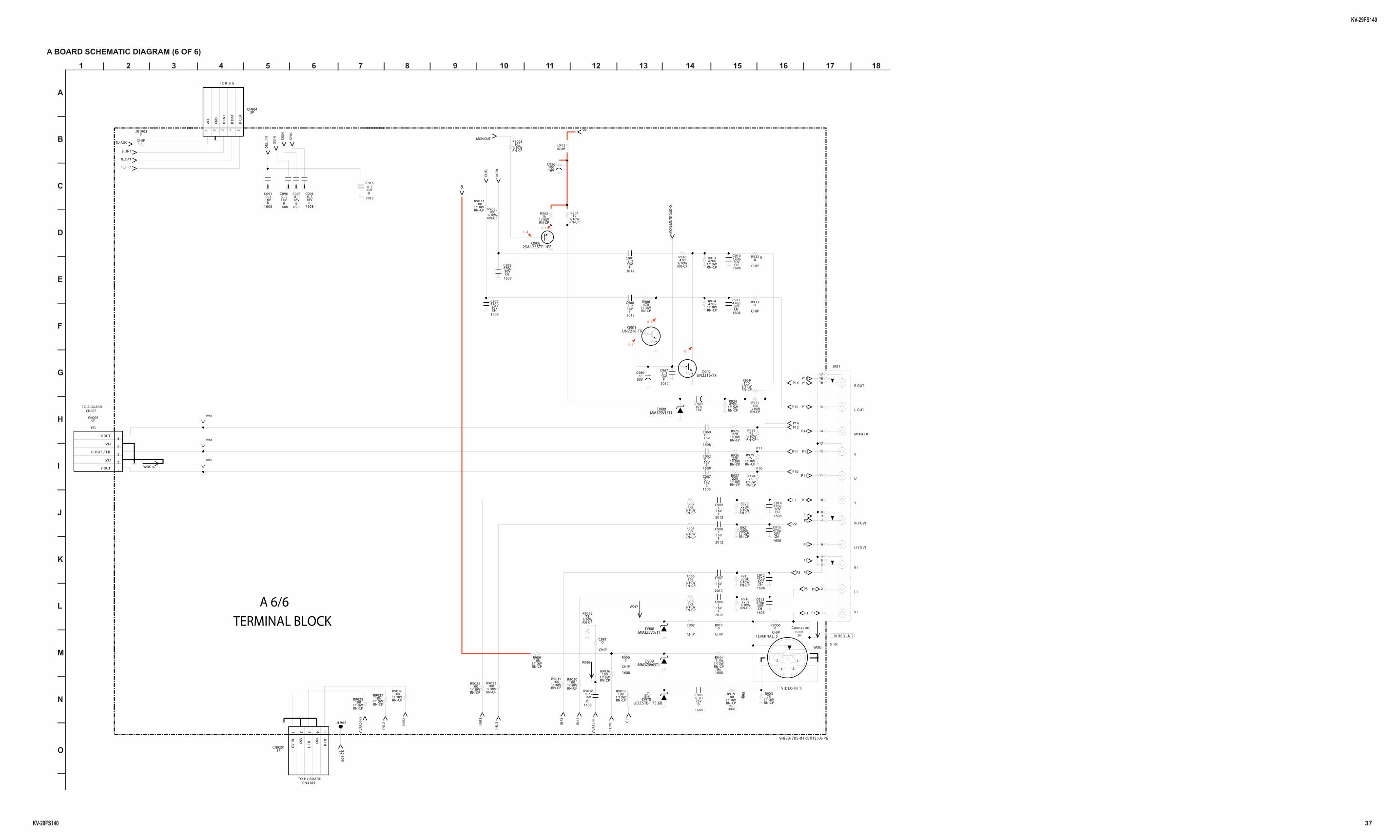
KV-29FS140
KV-29FS140 37
1 | 2 | 3 | 4 | 5 | 6 | 7 | 8 | 9 | 10 | 11 | 12 | 13 | 14 | 15 | 16 | 17 | 18
A
—
B
—
C
—
D
—
E
—
F
—
G
—
H
—
I
—
J
—
K
—
L
—
M
—
N
—
O
—
A BOARD SCHEMATIC DIAGRAM (6 OF 6)
W016
1
2
3
4
5
5PCN905
YEL
Y OUT
GND
U OUT / FB
GND
V OUT
1/10WRN-CP
10kR9026
P18
1/10WRN-CP
1kR904
RN-CP
220R927
1/10W
MM3Z5V6ST1D908
INL
3
CV
BS2
/Y2
1/10WRN-CP
100R9030
1/10WRN-CP
220kR915
1/10WRN-CP
100R9019
P14
W083
P5
1/10WRN-CP
R9036100
P1
5VRN-CP
220R926
1/10W
P12
1/10WRN-CP
220kR916
47uHL902
1/10WRN-CP
39kR907
UN2216-TXQ901
P11
1/10WRN-CP
100R9022
1/10WRN-CP
75R929
W017
1/10WRN-CP
220kR921
1/10WRN-CP
470R910
1/10WRN-CP
1kR902
1608
16V0 . 2 2
R9018
B
S2
00
1:7
K
INL
1
2012
16V1
F
C908
P7
SE
L_
IN
P3
16
08
1/10WRN-CP
R9017
5%
100
B_DAT
CHIP
0JR1903
1/10WRN-CP
75R9062
1/10WRN-CP
10kR9027
1/10WRN-CP
470kR913
2012
16V1
F
C906
1608
CHIP
R9900
34
12
Connector
TERMINAL, SJ900
8P
1/10WRN-CP
39kR905
S1
/VC
MM3Z5V6ST1D909
B_CLK
SY
IN
P11
1 2 3 4 5
5PCN9201 C
VIN GN
D
LIN G
ND
RIN
JL964
2012
25VB
C9160 . 1
1608
50V470p
CH
C922
16
08
1/10WRN-CP
R923
5% 75
RN-CP
220R925
1/10W
16V470
C903
1/10WRN-CP
100R9023
1608
50V470p
CH
C913
2012
16V2 . 2
F
C901
P9
1608
1/10WRN-CP
R919
5%
100
MON-OUT
1/10WRN-CP
R90939k
J901
1
2
3
6
7
45
89
10
11
12
13
14
15
16
1718
1608
16VB
C0950 . 1
1/10WRN-CP
75R928
P9
CV
BS1
/Y1
INR
2
P12
1608
50V470p
CH
C925
P15
1 2 3 4 5
5PCN904
AGC
GN
D
BIN
T
BD
AT
BC
LK
1608
50V470p
CH
C912
CHIP
R90060
0C981
CHIP
1/10WRN-CP
470kR924
C9020
CHIP
1/10WRN-CP
150R931
P16
INR
3
OU
TL
1/10WRN-CP
470R906
P16
P15
9V
OU
TR
16V0 . 1
C062
B1608
P3
2012
16V1
F
C907
P10
1/10WRN-CP
R98910k
1608
16VB
C0960 . 1
1/10WRN-CP
100R9025
1/10WRN-CP
100R9020
1/10WRN-CP
120R939
P9
CHIP
0R932 &
50V22
C980
C1
CHIP
0R911
1608
16V0 . 1
B
C093
1/10WRN-CP
100R9031
1/10WRN-CP
100R9028
INR
1
2012
16V2 . 2
F
C900
W005
P5
2SA1235TP-1EFQ900
P5
CHIP
0R933
W081 &
MO
N-M
UTE
-AU
DIO
1608
50V470p
CH
C914
UN2216-TXQ902
1608
1/10WRN-CP
R944
5%
1 . 5 k
INL
2
SV
IN
P10
16V0 . 1
C067
B1608
1608
16VB
C0940 . 1
W006
1/10WRN-CP
220kR920
1/10WRN-CP
75R930
B_INT
1/10WRN-CP
470kR914
16V100
C956
16V0 . 1
C060
B1608
1608
50V470p
CH
C910
1608
25VB
C9050 . 0 1
2012
16V1
F
C909
2012
16V2 . 2
F
C967
1608
50V470p
CH
C915
P7
UDZSTE-175.6BD910
P1
W007
SUIN
MM3Z9V1ST1D900
1/10WRN-CP
39kR908
P14
1608
50V470p
CH
C911
TU-AGC
P11
P10
0 . 1
V1
Y
R OUT
S I N
0 . 1
L OUT
U
MON OUT
R1
1 . 4
V I D E O I N 1
0 . 2
V
L1
L(YUV)
V I D E O I N 1
2 . 1
R(YUV)
TO A BOARDCN007
TO H2 BOARDCN4105
F O R J I G
9-883-705-01<BX1L>A-P6
A 6/6
TERMINAL BLOCK
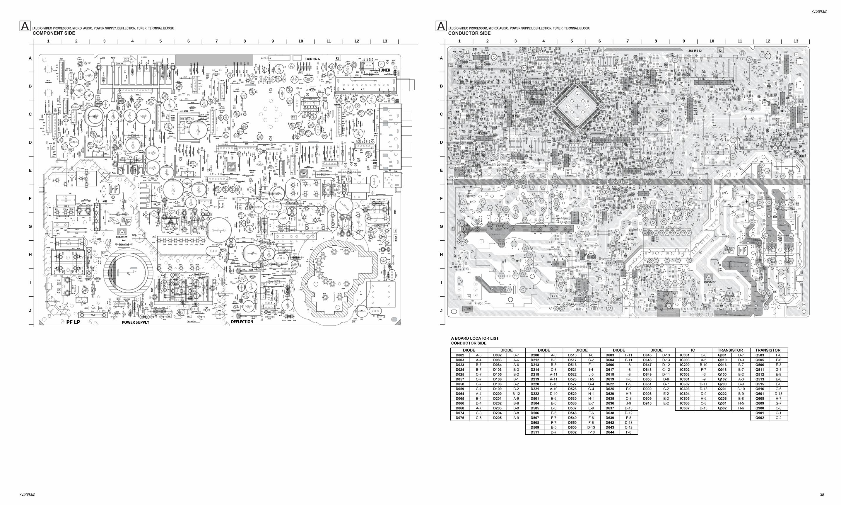
KV-29FS140
KV-29FS140 38
[AUDIO-VIDEO PROCESSOR, MICRO, AUDIO, POWER SUPPLY, DEFLECTION, TUNER, TERMINAL BLOCK]ACONDUCTOR SIDE
[AUDIO-VIDEO PROCESSOR, MICRO, AUDIO, POWER SUPPLY, DEFLECTION, TUNER, TERMINAL BLOCK]ACOMPONENT SIDE
EY558
EY559
W030
FB608
W032
W03
3
14 CN003
EY560
W034 17
CN004
EY561
EY562
EY563
1 5CN007
EY56
4
J900
EY56
5
J901
EY56
6EY
567
EY568
J904
EY569
J905
R605
J906
R606
J907
R607
19
CN01
0
J908
SWF100
EY185
G1G2O1O2
I
SWF102
IO
SWF103
EY57
0
IHILGO1O2
SWF104
EY57
1
EY57
2EY
573
R610R612
R616
EY194
R618
R619
C002
W053
W05
4
R234
C004
CN600
R235
C005
CN601
C006
CN602
W057
R620
1 3CN604
W059
R621
CN605
111
TU101
1
CN60
6
5
TU102
16
CN607
TU103
R624
C200
C201
R627
C204
C205
X001
W063
C013
C207
W064
W065
C209
W066
W068
R631
14
CN21
01
18
CN21
02
R633
13
CN2103
C210
14
CN21
04
C211
TP101
R636
C212
W070
C214
C215
C217W074
C024
W075
C219
C603
R640
C604
TH600
C029
C605
C607
C220C221
C609
C611
C036
C612
R650
R651
R653
C231
R656
C232
R658
R659
C236C237
PF LP
C238
C239
R660
C624
R661
C625
C626
C240
C628
C241
JW1031
C243
C050
C244
C245
JW1611
C246
JW16
12
JW16
13
C630
JW16
14
JW00
1
C055
JW16
15
JW00
2
C056C632
JW16
16
JW16
17
JW004
C634
JW16
18
JW005
C635
JW1619
JW00
6
C637
JW00
7
A503
JW00
8
C638
R675
C639
R676
JW200
R678
JW1620
JW201
JW16
21
EY001
JW16
22
EY002
JW16
23
EY003
C064
EY004
RY600
JW01
1
C065
C641
EY005
JW01
2
BCQ102
JW01
4
A511
JW20
9
R681
JW01
5
JW016
C646JW
017
C647
JW01
8
EY200
C649
EY201
EY20
2
JW21
3
C073
EY207
JW02
0
EY01
4
EY208
JW21
5
JW02
1
EY209
JW02
2
EY016
JW217
JW02
3
C653
EY017
JW02
4
C654
L100
JW601
JW02
5
17
CN31
01
L101
JW026JW
602
JW60
3
JW02
7
C657
JW604
JW028
C658
JW605
JW029
JW21
11
EBQ50
1
L106
E BQ502
JW60
7
JW22
0
JW60
8
JW60
9
JW22
2
JW800
C660
D218
JW801
D219
JW03
2
D602
JW22
7
D603
JW61
0
JW03
4
JW228
EY02
8
+-
D604
JW80
5
JW61
1
EY02
9
D605
JW61
2
JW03
6
D606
JW80
7
JW03
7
D607
JW03
8
JW808
C668
D220
D608
112IC200
JW61
5
JW809
JW03
9
D221
EY22
1
BE
Q51
1
L260
1JW
616
D222
EY22
2
R502
2
JW61
7
EY22
3
R502
3
JW23
0
JW61
8
D224
EY22
4
D225
EY225
EY03
2
R502
6
EB
Q51
6
L502
JW16
53
EY03
3
R5027
JW810
JW23
4
JW04
0
C670
JW1654
EY03
4
D228
JW041
EY035
JW23
6
JW042
JW81
2
JW81
3
JW237
JW04
3
L507
JW814
EY038
D614
EY03
9
D615
JW046
D617
JW62
4
D618
JW81
9
JW62
5
R215
1
D619
JW62
6
R215
2
R5032
JW62
7
JW628
JW24
0
EY040
JW62
9
EY041
L511L512
L513
JW05
0
JW820
D620
L514
JW16
65
D621 L515
1 7
IC601
JW052
C682
D622
IC602
JW823
I
O
G
IC603
JW16
68
JW824
JW05
4
EY048
D624
I
O
IC604
JW16
69
JW05
5
JW63
1
C685
EY049
D625
IC605
JW05
6
IO
IC606
L902
T602
JW82
7
JW05
7
C687
JW05
8
JW82
8
JW63
4
C688
JW05
9
C689
D629
JW16
70
JW63
8
JW16
71
JW63
9
EY052
JW06
0
C690
EY054
JW83
1
C691
EY055
JW06
2
JW832
EY056
JW06
3
C507
3
EY057
D633
JW64
0
JW064
EY058
JW06
5
JW64
1
EY059
JW06
6JW642
D636
JW06
7
JW06
8
JW838
JW06
9
D639
JW646
JW64
7
EY060
JW07
0
I O
D640
JW07
1
EY065
D641
JW07
2
D066
EY066
JW073
EY06
7
D644
JW074
EY06
8
JW07
5
EY069
JW07
6
W502
JW07
7
JW65
3
W503
JW654
JW07
8
W504
JW07
9
W506
JW656
JW65
7
FB503
JW658
EY072
JW08
0
JW08
1
EY07
6
JW08
3
EY07
7
JW08
4
JW08
5
JW08
7
JW08
8
JW66
5
JW08
9
R502
JW09
0
R121
JW099
R517
C123
3
13
CN503
1 4CN505
1 6
CN507
R525
C101
R528
C106
C107
C108
C302
C303
C304
CN903
R538
1
5
CN904
1
1CN905 51 6CN906
14
CN90
7
C118
C501
C502
C311
JW11
01
R543
C507
C120
C508
C509
R547
C317
R548
C514
R551
R555
C519
R557
C903
C904
TP601
A002
TP602
A003
A005
C521
A007
R562
C2602
S502
C528
R568
A010
A011
TP02
A013
TP03
A014
TP04
C531
A017
A019
C537
C538
C539
R577
R578
A020
JW101
R579
JW103
C540
JW10
5
DY1
JW106
A604
CT13
1
JW30
0
R585
A222
A223
D103
JW11
1
CT13
9
JW113
C550
JW11
5
JW117
R590
JW118
C556 C557
L003
R594
C558
L004
JW505
L005
R596
L006
R597
L007
L008
L009
JW12
2
JW123 JW12
4
L201
EY50
2
JW12
7
D503
EY503
JW51
0
JW128
L010
D504
EY504
JW511
C565
L011
EY505
JW2101
L012
EY506
JW2102
C567
L013
EY507
JW21
03
EY508
JW2104
EY121
JW2105
BE
Q605
JW21
06
JW21
07
JW21
08
EY124
JW2109
EY125
C956
EY126
JW133
EY12
7
JW134
C570
EY12
8
EY12
9
C572
EY512
JW13
7
JW1557
D513
EY513
JW2110
JW138
43 2
1
PH60
0
EY516
C577
D517
EY517
EY13
0
D518
EY51
8
L600
D519
EY51
9
L601
L602
C580
EY52
0
D521
EY52
1
CN61
01
2
1
D522
D523
17
62
IC503
EY524
L031
EY525
T501
L032
T502
T503
L033
D527
D528
L035
D529
EY529
T505
L036
T508
W002
D530
EY530
R264
5
EY531
W005
FB001
R2646
EY532
W006
R264
7
EY533
W007
EY534
EY535
PS20
1
EY53
6
PS202
C597
EY53
7
PS203
C980
EY538
EY539
EY155
FB20
1
EY15
6
FB202
EY157
FB20
3
EY158
EY540
EY159
EY541
EY542
W016
EY543
W017
EY544
W018
EY546
EY547
EY160
D548
EY548
EY161
EY549
EY162
EY163
EY164
EY165
15
CN92
01
EY166
PS602
EY167
PS603
D550
EY550
W024
PS604
EY551
PS605
CF10
1
FB601
EY557
FB603
4
FBTPOWER SUPPLY DEFLECTION
1-868-156-12A-1151- 201-A
TUNER
H+ H+H-H-V-V+
200V GND H1
135VNCGND
VMOU
T
BINT
BDAT
BCLK
STBY SW
GND
11V
R OUT
GND
IK
9V
YOUT
VOUT
UOU
T/FBGN
D
GND
DGC
DGCT
GND
AGC
G OUT
B OUT
ICT
16
12
4
5
6
7
8
9
11
14
13
H+135V
200V
H1
GND
GND
ABL
2
YO
UT
UO
UT/F
B
VOU
T
GND
GND
H-O
UTH. CENT.
V-OUT
ERR. AMP
AUDIO AMP.
SRT
LFT
SWITCHING REG.
PIN-OUT
GND
(TO
CVCN
701)
(TO
HCN
4102
)
GND
11V
MIC-SW
SP GND
SP GND
R
L
L INGNDCV IN
GND
R IN
SIRCS
GNDVCCGND
LED GLED R
KARA LGNDKARA R
MON L
GND
MON R
(TO
HCN
4108
)
(TO
HCN
4105
)
(TO
HCN
4103
)
(TO A CN905)
KEY
DGCT
BLK
LFT
R2
GND
SCLSDA
W011
GND
AC IN
AC IN
1 3
CHO
KE
CHO
KE
STBY-SWCENTER+CENTER+
CENTER+
30V
AFT
GNDIIS WSIIS CLKIIS OUT1
VD+
GND
5V 15V
-15V
ROT
CTRL
(TO CV CN1801)
SYO
UT GND
SUO
UT GND
SVO
UTSE
LOUT
FBP
15V
VD+
HP IN
VP IN
GND
CVBS/PIPOUT
ATSC
11V
NC ATSC
GND
3
10
DGC
DGCNCDGC
1 2
(TO
K)
GND
BINT
BDAT
BCLK
SR
GND
SL
A-MUTE
GND
A-STBY
4V
9V
3.3V
CBA
++
CENTER+
--
GND
ID JUMPERS
111 39 7
D074
JW60
6
JW811
JW50
6
R5020
JW047
CN509
EY528
C610
JW512
JW051
C026
JW03
5
R510
W011
JW62
1
JW05
3
JW22
6
JW048
JW04
9
JW06
1
JW091
JW086
W080
W079JW114
W078
R522
FB505
W031
W058
C693
EY574EY575
R682
FB50
4
JW1672
W077
1
JW16
67
FB611
JW1666FB605
FB61
0
C606
D223
Q506
GS
JW009CN013
14
GO1O2 I1I2
SWF101
T504
JW508
JW50
9
JW098
R591
JW20
6
JW513
EY57
6EY
577
R503
7
EY58
1
EY58
0
EY578EY579 R5038
R5039
C574
JW803
C666
C692
EY227
EY226
EY218
EY217 EY015
EY051EY050
EY220
EY219
T603T605
1
23
4
EY007
C523
JW08
2
W081
Q505
GS
C665
C249
JW802
W076
JW033
A200
C500
1
W010W083
W082
14
17
1 5
19
G2 G1O1O2 I
IO IHILGO1O2
1 21 3
1 3
1 3
111
15
#1#6
111 9 37
14
18
13
14
BC
17
BE
E B
+-
121
BE
BE
1 7
IOG
IO
IO
I O
13
1 4
#1 #6
1 41 5
1 5
#1 #6
14
BE
123
4
21
17
62
15
111 9 7 3
GS
14
GO1O2 I1I2
1
23
4
GS
1
A
B
C
D
E
F
G
H
I
J
2 3 4 5 6 7 8 9 10 11 12 13
BE
B E
BE
JR
JR
JR
JR
JR
JR
JR
JR
JR
BE
14
5 8
JR
JR
JR
JR
BE
JR
JR
BE
B E
B E
B E
B E
BE
JR
JR
JR
JR
JR
JR
JR
JR
JR
JR
JR
JR
JR
JR
JR
JR
JR
JR
JR
B E
B E
BE
BE
B E
B E
B E
JR
JR
JR
JR
BE
JR
B E
JR
B E
B E
JR
JR
#B#E
JR
JR
JR
#8
#1#4
#5
JR
JR
1
3
233
64 65
96
97
128
JR
JR
JR
BE
BE
R019
W030
R210
FB608
R211
W032
R212
W033
R213
14
CN003
W034
R020
R214
1
7
CN004
R215
R022
R216R023
1
5
CN007
R024
R218
J900
R025
J901
R026
R602
R603
J904
R604
R029
J905
R605
J906
R606
J907
R607
R220
19
CN010
J908
R608
SWF100
R221
R609
G1 G2
O2
I
SWF102
O
ISWF103
R030
IH IL GO1
SWF104
R610
C1329
R612
R038
R039
R616
R9006
R9007
R618
R9008
R619
R9009
C001
C002
W053
C003
W054
R234
C004
CN600
R041
R235
C005
CN601
R042
R236
C006
CN602
W057
R237
R044
R238
R620
R9010
13
CN604
W059
R045
R621
CN605
TU101
R046
CN606
15
TU102
R623
16
CN607
TU103
3
R048
R624
C200
R9015
C201
C202
R627
R9017
C203
R9018
C010
C204
R241
R9019
C205
X001
R242
C012
C206
W063 R243
C013
C207
W064
C014
C208
W065
R051
C209
W066
W068
R9020
C018
R631
R9021
14
CN2101
R0
56
R9022
1
8CN2102
R633
R9023
13
CN2103
R058
R634
C210
1
4
CN2104
R059
R635
R9025
C211
TP101
R636
R9026
C212
R9027
C213
W070
R9028
C020
C214
C021
C215
C022
C023
C217
W074
R060
C024
W075
R061
C025
C219
C027
C603
R640
R9030
C028
C604
TH600
R9031
C029
C605
C607
C220
C221
C609
R9036
R647
C030
C031
C0
32
C034
C611
C036
C612
C037
R650
C038
R651
C616
R653
R654
R655
C231R656
C232
R658
C234
R659
C041
C235
C042
C236
C237
C044
C238
C239
C046
C623
R660
C048
C624
R661
C049
C625
C626
R088
C240
C628
R665
C241
R666
R667
C243
R668
C050
C244
R669
C245
JW1611
C052
C246
C053
C247
C054
C248
C630
C055
C056
C632
C057
C634
R9061
C635
R096
R672
R9062
R9063
R097
C637
A503
C638
R099
R675
C639
R676
R677
R678
C060
R679
C061
C062
D002
C063
JW1623
D003
C064
D004
Q100
RY600
C065
C641
D005
D006
B
C
Q102
C067
C643
D007
Q103
R680
C644
D008
Q104
JR1100
A511
JR001
R681
C069
JR1101
C646
JR1102
JR003
C647
D200
R5000
C649
D201
R5001
D202
R5002
JR007
D203
R5003
JR008
C070
D204
JR009
JR1109
D205
R5005
C072
D206
R5006
C073
D207
D208
R5008R5009
JR203
C653
C654
JR1110
L100
JR1111
17
CN3101
L101
JR1112L102
JR013
C657
L103
JR014
C658
R5010
R5011
L105
E
B
Q501
JR016
D212
R5012
L106
EBQ502
D213
R5013
Q503
C080
D214
R5014
C081
D215
R5015
D216
D023
D217
IC003
C660
D024
D218
D600
C661
D025
D219
C662
D602
D603
+-
D604
C089
D605
D606
D607
JR600
C668
D220
D608
112 IC200
JR601
D221
R5021
BE
Q511
L2601
JR602
JR026
D222
R5022
Q512JR603
JR027
R5023
Q513
C090
D224
R5024
C091
D225
R5025
Q515
C092
R5026
EB
Q516
L502
C093
JW1653
R5027
C094
C670
JW1654
D228
Q900
C095
Q901
C096
C672
Q902
C097
L507
Q903
JR030
JR800
C098
C674
D614
JR031C099
C675
D615
JR802
D617
JR1903
C678
D618
JR805
C679
R2151
D619
JR1905
JR036R2152
R5032
JR1906
JR037
R5034
R5035
L511
R5036
L512
L513
C680
D620
L514
D621
L515
7
IC601
1
C682
D622IC602
I
O
G
IC603
D624
OI
IC604
C685
D625
IC605
C686
JR042
IO
IC606
L902
T602
C687
C688
JR044
C689
JR045
D629
JR049
C690
C691
FB101
C5073
D057
D633
D058
JR051
D059
D635
D636
D637
D638
D639
D064
IO
D640
R100
D065
D641
D642
D066
D643
R103
D644
D068
R104
R106
W502
R107
W503
R108
W504
R109
W506
JR2107
FB503
C1019
R110
D075
R111R112
R306
R113
D078
R114
JR071
D079
R115
JR072
R116
JR650
R118
R500
JR651
R119
R501
JR652
R502
JR653
R503
D080
JR654
R504
D081
JR655
R505
R1001
R506
R1002
R314
R121
R315
R316
FB902
R317
FB903
JR5001
R126
R127
R128
R513
R320
R514
R515
R516
R323
R517
R324
R518
R131
R519
R902
C1233
R904
R905
R906
13CN503
R907
R520
R908
R521
R909
14
CN505
R523
1
6
CN507
R524
C100
JR0
99
R525
C101
R526
C102
R527
R528
R910
C104
R529
R911
R336
C106R337
R913
C107
R338
R914 C108
R339
R915
C109
R146
R916
R147
R917
R148
R530
R918
C300
R149
R531
R919
C301
R532
C302
R533
C303
R340
C304
R341
R535
C111
R536
C112
R537
4 1
CN903
R150
R538
R920
C308
15
CN904
R539
R921
C115
15
CN905
R152
R922
C116
16 CN906
R153
R923
C117
14
CN907
R154
R924
C118
R155
R925
C119
C501
R156
R926
C502
R927
C503
R928
JR5035
R929
C311
C505
R542
C312
R543
C313
C507
R544
C120
C508
C509
C316
R547
C317
R548
R930
C318
R355
R931
C319
R356
R932 R933
R934
R935
C511
R936
C512
R937
C513R938
C320
C514
R939
R551
C321
C322
C516
R553
C323
C517
R554
C324
C518
C900
R555
C131
C325
C519
C901
R556
C132
C902
C133
C903
R364
C328
C904
C135
C329
C905
TP601
C906
A002
TP602
C137
C907
A003
R944
C138
C908
A005
C521
C909
A007
R560
C330
C524
C331
C2601
R562
C332
C2602
S502
C333
C527
C140
C334
C528
C910
C141
C911
C142
C912
C143
C913
R568
C144
C914
A010
C145
C915
A011
C146
C916
TP02
R377
C147
A013
TP03
C148
A014
TP04
R379
C531
A017
R571
A019
C537
R380
C538
C539
C922
R577
R384
R578
A020
R385
R579
C925
R386
C540
DY1
Q001
R580
A604
CT131
R582
D100
R585
A222
R392
JR1006
D102
R393
A223
D103
R394
R395
CT139
D105
Q201
D106
Q202
D107
C550
Q010
D108
R399
D109
Q206
R590
JR1010
JR1011
C556
Q016
JR1012
C557
L003
R594
C558
Q018
D110
L004JR1015
D111
L005R596
L006
R597
L007
L008
JR301
R599
L009
JR302
JR303
JR304
L201
D501
D502
D503
L010
D504
R989
C565
L011
D505
JW2101
Q601
L012
D506
C567
L013
D507D508
D509
B
E
Q605
JR501
JR1601
JR502
Q606
JR1602
JR504
R990
Q608
Q609
JR506
C956
C570
JR509
D511
C572
JW1557
D513
Q610
12
34
PH600
C577
D517
C578
D518
D900
L600
JR511
D519
D901
L601
JR512
D902
L602
JR513
D903
D904
D905
C966
D906
C967
D907
C580
C968
D908
C969
D521
D909
CN6101
D522
IC502
D523
1
2
67 IC503
L031
T501
L032
T502
T503
C587
L033
D527
C588
C970
D528
D910
C971
L035
D529
D911
T505
L036
D912
D913
D914
T508
W002
C590
D530
R2645
W005
FB001
C592
R2646
W006
FB002R2647
W007
JR1050
FB005
PS201
C596
D536
FB006
PS202
C597
D537
FB007
PS203
C598
C980
FB008
C981
FB009
C982 FB201
FB202
FB203
FB010
R001
W016
R002
W017
R003
W018
R004
JR1256
R006
R007
D548
R008
D549
R009
R200
15
CN9201
R201
PS602
R202
PS603
R203
D550
W024
R010
PS604
R204
R011
PS605
R205
CF101
R012
R206
R013
R207
R014
R208
R015
FB601
R016
FB603
4 1
85
1 128
32
33
64 65
9697
1 23
4
5
6
7
891011
14
13
FBT
DGCT
DGC DGC
DGCT
GNDU
OUT/FB
VO
UTGND
H+ H+ H- H- V- V+
GNDBINT
BDATBCLK
YO
UT
AGC
B OUTG OUTR OUTGNDIK9V
16
21
H+
+B
200V
H1
GND
ABL
30
10
20
MIC SW
11V
R
L
SP GND
L INGNDCV IN
GNDR IN
GNDVCCGND
LED GLED RKEY
GND
R2
GND
KARA LGNDKARA RMON L
GNDMON RGNDSCLSDA
CHOKECHOKE
ACIN
ACIN
ATSC11V
ATSCGND
NC
GND
STBY SW
30V
AFT
STBY SW
GND
11V
VD+GND5V15V
-15VRO
TCTRL
200V
GNDH1FBPGND
15V
VD+
SYO
UT
SUO
UT
SVSEL
GN
D
GN
D
HP IN
YO
UTGNDU
OUT/FB
GNDV
OUT
GNDIIS WSIIS CLKIIS OUT1
135V
NC GND VM OUT
-
-
CENTER+
CENTER+CENTER+
CENTER+
+
+
1-868-156-12
GND
3.3V
9V
SRGNDSL
SP GND
SIRCS
VP INGNDCVBS/PIPOUT
A-MUTE
GNDA-STBY
4V
1
3
2
13 9 117
D647
D645
D646
R5020
CN509
C610
C026
R510
W011
W080
W079
W078
W031
W058
JR522
JR503
JR1606
JR1605
D650JR801
D649
D648
D082
D083
JR052
D084
C693
R522
R682
FB505R557
FB504
D074
W077
OU
TO
UT
DGCDGCNC
12
1
FB611
FB605
FB610
C606
D223
Q506
GS
IC001
CN013
14
GO2
I1 I2
SWF101
O1
T504
JR667
JR666
R591
R5037
R5038
R5039
C574
C666
C692
T603T605
1 4
32
C523
IC607
Q200
W081
JR668
Q505
G S
C665
R021
C335
D651
FB011
Q111
C249
W076
A200
C5001
W010
C694
W083
W082
BE
B E
BE
JR
JR
JR
JR
JR
JR
JR
JR
JR
BE
14
5 8
JR
JR
JR
JR
BE
JR
JR
BE
B E
B E
B E
B E
BE
JR
JR
JR
JR
JR
JR
JR
JR
JR
JR
JR
JR
JR
JR
JR
JR
JR
JR
JR
B E
B E
BE
BE
B E
B E
B E
JR
JR
JR
JR
BE
JR
B E
JR
B E
B E
JR
JR
#B#E
JR
JR
JR
#8
#1#4
#5
JR
JR
1
3
233
64 65
96
97
128
JR
JR
JR
BE
BE
1
A
B
C
D
E
F
G
H
I
J
2 3 4 5 6 7 8 9 10 11 12 13
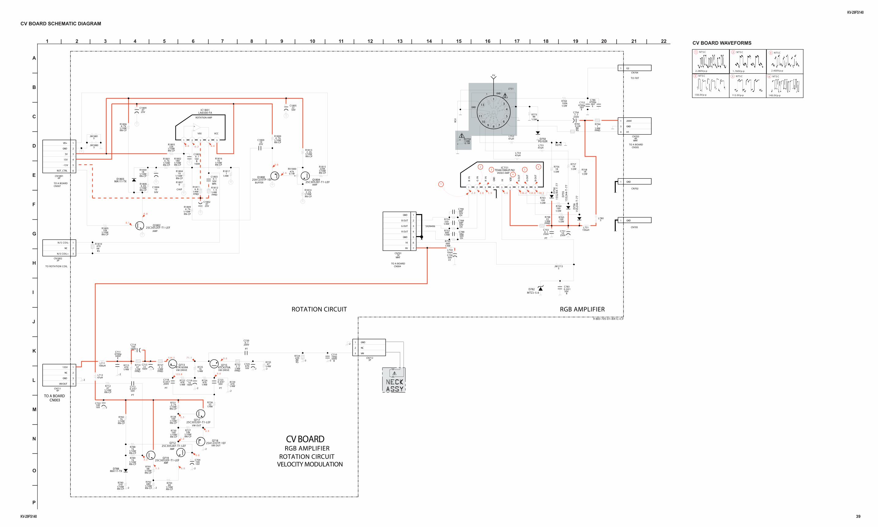
KV-29FS140
KV-29FS140 39
1 | 2 | 3 | 4 | 5 | 6 | 7 | 8 | 9 | 10 | 11 | 12 | 13 | 14 | 15 | 16 | 17 | 18 | 19 | 20 | 21 | 22
A
—
B
—
C
—
D
—
E
—
F
—
G
—
H
—
I
—
J
—
K
—
L
—
M
—
N
—
O
—
P
CV BOARD SCHEMATIC DIAGRAM
2SA1235TP-1EFQ1800
1S
S2
44
-T-7
7D
755
1/10W47
R712
RN-CP
50V22
C1805
- 2
- 2
1/4W47
R735
1
2
3
3PCN712
GND
NC
VM
R18142 . 2 k
1/10WRN-CP
- 2
1/10WRN-CP
1kR1816
1/2W1K
R756
50V
PT
0.047C712
47uHL754
50V22
C756
1/4W47k
R726
1/2W100kR760
1/4W680
R753
2SC3052EF-T1-LEFQ717
3WRS
R7810 . 6 8
1/4W1
R1817
1/2W100
R765
1/10W2 . 7 kR731
RN-CP
2SC3052EF-T1-LEFQ719
250V2 . 2
C754
2WRS
220R724
100uHL711
1/10W6 . 8 k
R1808
RN-CP
- 2
1/4W47k
R722
2kVE
C7864700p
250V10
C751
1/10W68
R793
RN-CP- 2
R1815220k
1/10WRN-CP
1/4W2 . 2
R732
FPRD
SG701
16V470
C725
1S
S2
44
-T-7
7D
754
1
2
3
3PCN1802
N/S COIL-
NC
N/S COIL+
1/10W1k
R788
RN-CP
MA111-TXD788
1608
16V0 . 1
B
C1801
200V
PT
0.047C718
KTA1659AQ713
160V22
C713
1/2W1K
R758
5JW1881
1
CN702
GND
160V10
C719
3
4
5
6789
10
11
13
1
GND
GND
1
J751
50V
PT
0.047C723
1
CN705
GND
1/10W100
R728
RN-CP
CHIP
0R1807
1/4W1k
R725
1WRS
470R1810
- 2
1/4W680
R752
1/4WFPRD
1 . 5R1812
1/10W4 . 7 k
R1800
RN-CP
200V
PT
0 . 1C720
2SC3052EF-T1-LEFQ1804
1
2
3
4
5
6
6PCN1801
VD+
GND
5V
15V
-15V
ROT_CTRL
1/4W330R754
- 2
1/10WRN-CP
4 . 7 kR1809
50VMPS
0 . 1C1803
1/4W2 . 2
R737
FPRD
1/4WFPRD
1R794
1/10W100
R730
RN-CP
1/2W100
R763
2SC3052EF-T1-LEFQ712
250V0 . 1
C753
PT
1/2W1M
R773
50V68P
CH
C789
- 2
10uHL750
L751150uH
1/4W22
R736
1/2WFPRD
47R714
1/10WRN-CP
180R1802
50V68P
CH
C790
25V47
C1809
5JW1713
1/4W470
R729
C7830.00150V
B
1/4W470
R715
2SA1235TP-1EFQ718
1/4WFPRD
6 . 8R1811
KTC4370AQ715
5JW1880
0.1W47k
RV1800
16V100
C704
MA111-TXD1803
- 2
1/10W4 . 7 k
R1806
RN-CP
1/2W100R764
47uHL712
PG102RD750
1/10WRN-CP
22kR1803
16V100
C722
1/10W270
R790
RN-CP
1 2 3 4 5
IC1801LA6500-FA
1
3
4
WHT4P
CN703
200V
GND
H1
50V68p
CH
C788
2kV4700p
E
C752
- 2
- 2
1/4WFPRD
22R798
500V100p
B
C710
1/10W10k
R1805
RN-CP
2SC3052EF-T1-LEFQ1802
1
2
3
4
4PCN711
135V
NC
GND
VM OUT
160V100
C714
- 2
MTZJ-5.6D782
1/10W680
R792
RN-CP
47uHL752
1/2W1K
R757
47uHL753
1
CN704
G2
1/10W10k
R727
RN-CP
500V4700p
E
C711
- 2
25V47
C1802
1/10WRN-CP
1kR1804
1S
S2
44
-T-7
7D
756
1 2 9876543
TDA6108AJF/N2IC751
BIN
GIN
RIN
GN
D
IK VDD
RO
UT
GO
UT
BO
UT
25V10
C1800
1/10W1k
R789
RN-CP
1/10W1k
R782
RN-CP
1
2
3
4
5
6
7
7PCN701
WHT
GND
B OUT
G OUT
R OUT
GND
1K
9V
1/10WRN-CP
4 . 7 kR1801
R18132 . 2 k
1/10WRN-CP
50V10
C1804
- 2
1/10W68
R791
RN-CP
L7805
110MRV750
0.1W
RN-CP
R18301K
1/10W
- 2
SIGN406
+
TO A BOARD
ROTATION CIRCUIT
CN507
-
RGB AMPLIFIER
CN505
CV BOARD
FV
CN004
TO FBT
VEE
RCV
TO A BOARDTO ROTATION COIL
TO A BOARD
VCC
1
23
4
56
VIDEO AMP
AMPBUFFER
ROTATION AMP
AMP
VM DRIVE VM DRIVE
AMP
AMP
VM OUT
VM OUT
2 . 0 2 . 0 1 . 9 4 . 6 136.2 134.0 138.3
3 . 0
2 . 6
0 . 0- 0 . 20 . 0
0 . 8
0 . 1
134.3 7 1 . 1
133.8 0 . 6
0 . 0
4 . 9
0 . 0
0 . 01 . 5
2 . 2
5 . 2
5 . 5
CN003TO A BOARD
9-883-705-01<BX1L>CV
RGB AMPLIFIERROTATION CIRCUIT
VELOCITY MODULATION
2.280V p-p
NT S C1
1.760V p-p
NT S C2
2.400V p-p
NT S C3
158.0V p-p
NT S C4
112.0V p-p
NT S C5
148.0V p-p
NT S C6
CV BOARD WAVEFORMS
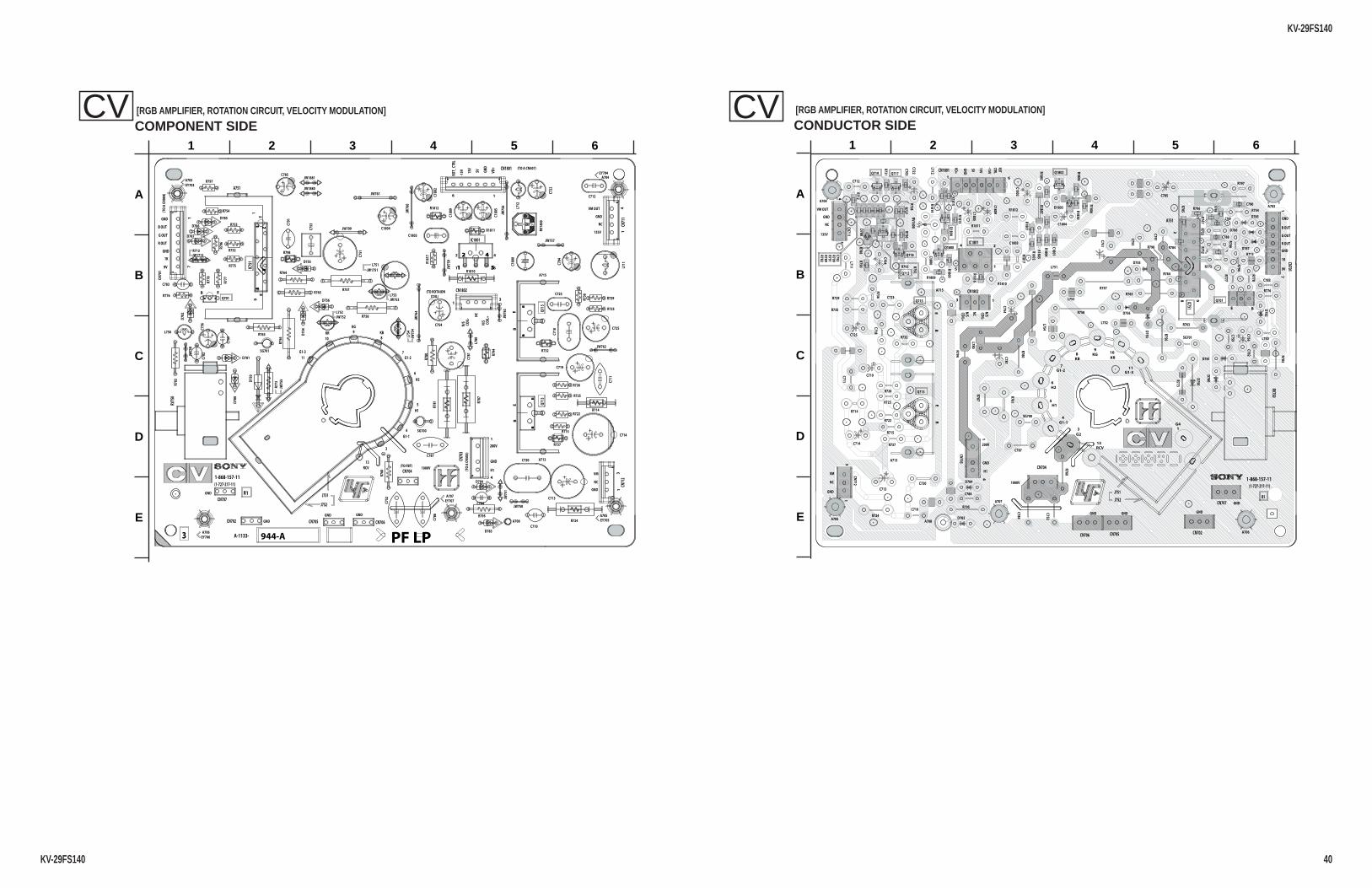
KV-29FS140
KV-29FS140 40
COMPONENT SIDE[RGB AMPLIFIER, ROTATION CIRCUIT, VELOCITY MODULATION] CV
CONDUCTOR SIDE[RGB AMPLIFIER, ROTATION CIRCUIT, VELOCITY MODULATION] CV
EB
1 5
2 4
17
1 3
14
14
13
BE
BE
28
91
#1#6
3
EB
4
5
2
1
17
13
1
4
14
13
BE
BE
1
29
8
11
10
98
7
3
13
G2
G1-2
KG
KR
G1-3
RCV
6
5
4G1-1
H1
H2
KB
A-1133- 944-A
1-868-157-11(1-727-217-11)
R1VD
+
GND
5V15VCT
RLRO
T
200V
GND
H1
B OUT
G OUT
R OUT
GND
1K
9V
1000V
GNDGND
GND
GND
GND
(TO A CN507)-
(TO
ACN
505)
(TO
ACN
004)
(TO FBT)
GND
NC
VM
135V
NC
GND
VM OUT
-15V
N/S
COIL
-
N/S
COIL
+NC
(TO ROTAIONCOIL)
JW75
8
JW75
9
D750
JW76
0
D754
JW761
D755
JW762
D756
JW76
3
JW76
4
D780
D781
D782
D783
D784
D785
D786
D787
A708
RV18
00
SG700
SG701
L711
L712
JW1880
JW1881
C180
0
C180
2
C1803
L750
C1804
L751
C180
5
L752
L753
L754
C180
9
R713
R714
R715
CN70
1
R722
R724
R725
R726
R729
R732
L780
R735
R736
R737
R1810
R1811
R1812
R181
7
C704
C710
C711
C712
C713
C714
R752
R753
A713
R754
C718
A715
C719
R756
R757
R758
C720
C722
C723
R760
C725
R763
R764
R765
JW1713
R773
R775
R776
R777
R778
R780
R781
R783
R787
C751
C752
C753
C754
C756
R794
R795
C759
R796
R797
JW709
EY703
EY704
EY705
EY706
EY707
JW1751
C781
C782
C783
C784
C785
C786
C787
C791
JW75
1
JW752
JW753
JW75
4
JW75
5
JW75
6
JW757
PF LPQ
715
Q71
3
Q701
IC751
RV75
0
CN707
CN702 CN705 CN706
CN704
CN1801
CN71
1CN
712
CN70
3
CN1802
IC1801
J752
J751
A751
JW750
16
R798
A703A704
A705
A706
A707
EB
1 5
2 4
17
1 3
14
14
13
BE
BE
28
91
#1#6
1
A
B
C
D
E
2 3 4 5 6
BE
B E
B E
B E
B E
BE
BE
BE
1
24
5
17
13
14
14
13
BE
BE
2
1
8 9
RCV
G4
G2
G1-1
G1-2
KBKG
KR
G1-3
1
11
109
8
7
4
3
13
H1
H26
5
1-868-157-11(1-727-217-11)
R1
B OUT
G OUT
R OUT
GND
1K
9V
200V
GND
H1
VD+
GND
5V
15V
ROTCTRL
GND
GND
GNDGNDGND
1000V
-15VN/SCO
IL-
N/SCO
IL+
NC
NC
135V
GND
VM OUT
VM
NC
GND
D750
D754
D756
D780
D781
D782
D783
D784
D785
D786
D787
A708
RV1800
SG700
SG701
L711
L712C1800
C1802
C1803
L750
C1804
L751
C1805
L752
L753
L754
C1809
R713
R714
R715
CN703
R722
R724
R725
R726
R729
CN711
CN712
R732
L780
R735
R736
R737
R1810
R1811
R1812
R1817
C704
C710
C711
C712
C713
C714
R752R753
A713
R754
C718
A715
C719
R756
R757
R758
C720
C722
C723
R760
C725
R763
R764
R765
R773
R775
R776
R777
R778
R780
R781
R783
R787
C751
C752
C753
C754
C756
R794
R795
C759
R796
R797
C781
C782
C783
C784
C785
C786
C787
C791
R784
R767
C703
R1804
R1808
R727
C789
R1814
C1801
R1807
R791
R788
R1806
R1800
R792
R789
R730
R790
R785
R768
R793
R1813
R731
D1803
R712
R766
R1803
R786
R1805
C790
R1801
R1830
R1815
R782
R1816
R1802
D788
C788
R1809
R728
RV750
IC751
CN701
CN1801
IC1801
CN704
CN1802
CN706 CN705 CN702
CN707J752
J751
A751
Q701
Q1802
Q1804
Q1800
Q712
Q717Q719
Q718
Q715
Q713
1 6
R798
D755
R799C792
A703A704
A705
A706
A707
BE
B E
B E
B E
B E
BE
BE
1
A
B
C
D
E
2 3 4 5 6
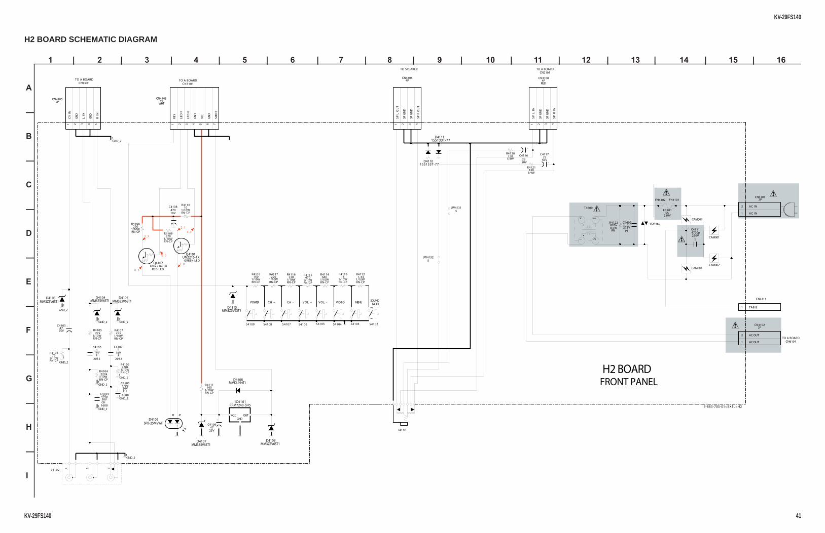
KV-29FS140
KV-29FS140 41
1 | 2 | 3 | 4 | 5 | 6 | 7 | 8 | 9 | 10 | 11 | 12 | 13 | 14 | 15 | 16
A
—
B
—
C
—
D
—
E
—
F
—
G
—
H
—
I
H2 BOARD SCHEMATIC DIAGRAM
FH4102
1GND_2
1GND_2
1GND_2
VCCGND
OUT
RPM7240-SH5IC4101
1/10WRN-CP
220R4108
1/10W330
R4116
RN-CP
1 2 3 4
4PCN4106
SP
LO
UT
SPG
ND
SPG
ND
SP
RO
UT
MM3Z5V6ST1D4109
2012
16V1
F
C4107
1/10W220
R4117
RN-CP
50V22
C4116
UN2216-TXQ4102
0.5WRN
R4122820k
1 2 3 4 5 6 7
WHT7P
CN4103
KEY
LED
R
LED
G
GN
D
VCC
GN
D
SIR
CS
MM3Z5V6ST1D4105
2012
16V1
F
C4105
1 2 3 4
4PCN4108
RED
SP
LIN
SPG
ND
SPG
ND
SP
RIN
1/10W470
R4115
RN-CP
1GND_2
MM3Z5V6ST1D4103
L RV
J4102
S4102
211
GND_2
CAM002
1
2
2PCN4101
AC IN
AC IN
MMDL914T1D4108
MM3Z5V6ST1D4107
1SS133T-77D4110 50V
22C4117
S4104S4105
1/10W680
R4114
RN-CP
5JW4131
CAM003
MM3Z5V6ST1D4115
1/10W1 . 5 k
R4112
RN-CP
1/10WRN-CP
27kR4107
25V47
C4109
1GND_2
1/4W330
R4120
CAM001
1
GND_2
J4103
10V470
C41081/10WRN-CP
10R4110
FH4101
275VPT
0 . 6 8C4602
1/10WRN-CP
27kR4105
1SS133T-77D4111
250V5A
F4101
GR
SPB-25MVWFD4106
1608
50V470p
CH
C4106
1/10WRN-CP
220R4109
UN2216-TXQ4101
5JW4132
1/10WRN-CP
100R4111
MM3Z5V6ST1D4104
S4106
1/10WRN-CP
220kR4106
CAM004
S4109
1
2
2PCN4102
AC OUT
AC OUT
1GND_2
1 234
T4600
S4103
1/4W330
R4121
1GND_2
1/10W1k
R4113
RN-CP1/10W
150R4118
RN-CP
250V4700p
E
C4111
1
CN4111
TAB B
S4107
1
GND_2
1/10WRN-CP
75R4103
VDR460
1608
50V470p
CH
C4104
1 2 3 4 5
5PCN4105
CV
IN
GN
D
LIN
GN
D
RIN
25V47
C4103 S4108
1/10WRN-CP
220kR4104
GREEN LED
V O L -
2 . 0
3 . 3
RED LED
CN3101
MENU
TO SPEAKER
CH +
FRONT PANEL
MODE
0 . 3
H2 BOARD
VOL +
3 . 3
TO A BOARD
TO A BOARD
POWER C H -SOUND
2 . 1
VIDEO
CN2101
0 . 0
TO A BOARDCN6101
TO A BOARDCN9201
9-883-705-01<BX1L>H2
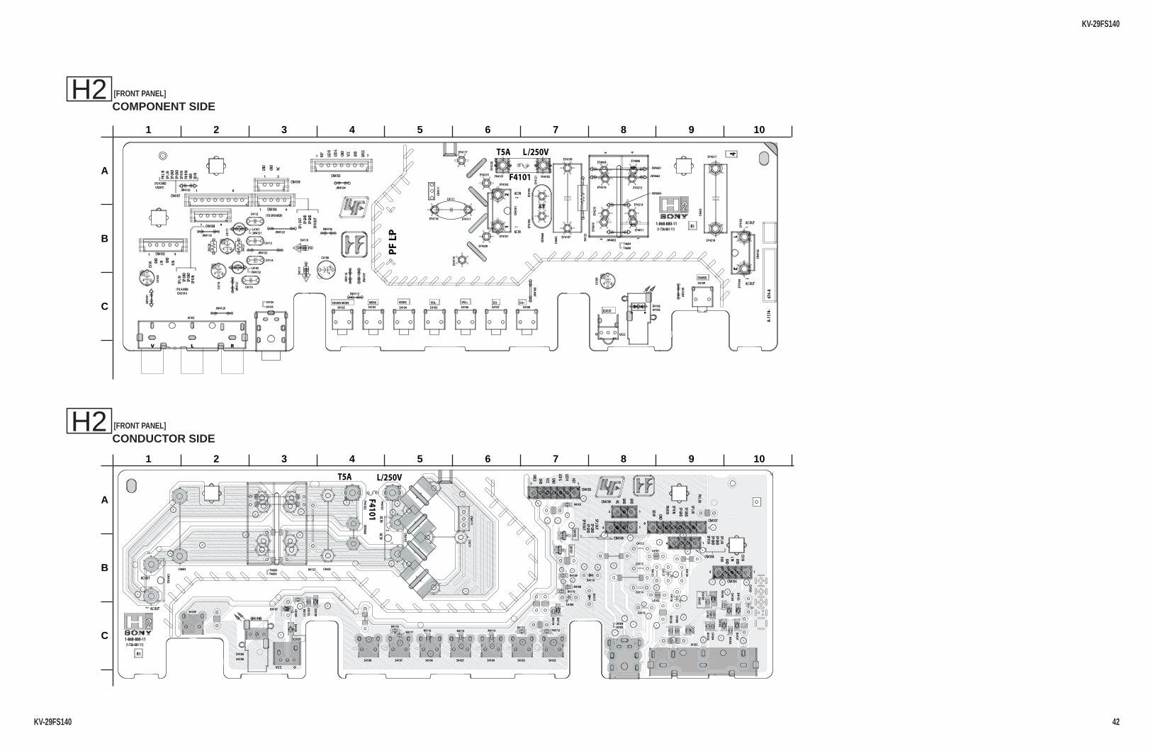
KV-29FS140
KV-29FS140 42
COMPONENT SIDE[FRONT PANEL] H2
CONDUCTOR SIDE[FRONT PANEL] H2
O VCC
21
V L R
21
1 7
14
1 5
RG
1 41 8
1 4
1 3
4
O VCC
1 7
123 4
1 5
1 4
1 8
1 4
1 3
1-868-880-11(1-726-881-11)SP
LOUT
SPGN
D
PHLI
N
PHRI
N
GND
GND
LIN
RIN
CVIN
LED
R
LED
G
GND
VCC
GND
AC IN
AC IN
AC OUT
AC OUT
1 1
2
2
(TO K BRDCN207)
(TO A BRDCN2101)
(TO SPEAKER)
KEY
R1
T5A L/250VSIRCS
GND
3DIN
474-
A
SPRO
UTSP
GND
GND
NCGND
SPGN
DSP
GND
SPLI
N
SPRI
N
SPRI
N
SPLI
N
SPGN
DSP
GND
SOUND MODE MENU VIDEO VOL- VOL+ CH- CH+
A-11
74-
J4102
C460
2
EY4008EY4009
EY40
10
EY4011
EY42
13
EY4214
EY4215EY4216
VDR4
60
L4101
L4102
JW41
01
JW4104
JW4106
JW41
07
JW41
16
JW4122
JW4123
JW4129
JW4131
JW4132
T4604
A4106
CN41
01
CN41
02
CN4103
CN4105
CN4106
CN4107
CN4108
CN4109
S4109
FH4101
C410
3
CN41
11
C4108
C410
9
C4111
C4112
C4113
C4114
C4115C411
6
C411
7
EY4101
EY4102
EY41
03EY
4104
D4106
IC4101
D4110
D411
1
EY4111
EY4117
EY4118
EY41
19
EY41
20
EY41
21
S4102 S4103 S4104 S4105 S4106 S4107 S4108
F4101
EY41
95EY
4196
EY4197
EY4199
JW4661
JW4662
JW4663
JW4664
C460
3
EY4217
EY4218
JW4112
EY4219 FH4102
EY4220
JW41
09
JW41
08
POWER
JW4135
PF
LP
JW41
21JW4118
T4600
R412
2
R412
1
R412
0
J4103J4104
O VCC
21
V L R
21
1 7
14
1 5
RG
1 41 8
1 4
1 3
1
A
B
C
2 3 4 5 6 7 8 9 10
BE
BE
OVCC
17
15
14 18
14
13
(1-726-881-11)1-868-880-11
AC OUT
AC OUT
ACINACIN
2
21
1
R1
T5A L/250V
RIN GND
CVINGNDLIN
SPRINSPGNDSPGNDSPLIN
3DIN GND
PHRIN
SPRIN
SPGNDSPGND
SPLIN
PHLIN
GND
GNDNC
SPLOUTSPGNDSPGND
SPROUT
KEY
LEDR
LEDGGND
VCC
GND
SIRCS
R4115
R4107
D4104
R4110
D4107
R4112
D4108
D4101
R4119
R4101
C4105
R4116
R4108
D4115
R4106
C4107R4117
R4109
D4105
C4110
D4109 C4106
R4113
R4104
D4102
Q4101
R4118R4114
R4105
D4103
Q4102
R4111
R4103
C4104
J4102
C4602
VDR460
L4101
L4102
T4604
A4106
CN4101
CN4102
CN4103
CN4105
CN4106
CN4107
CN4108
CN4109
S4109
FH4101
C4103
CN4111
C4108
C4109
C4111 C4112
C4113
C4114
C4115
C4116
C4117
D4106
IC4101
D4110
D4111
S4102S4103S4104S4105S4106S4107S4108
F4101
C4603
FH4102
T4600R4122 R4121
R4120
J4103J4104
BE
BE
1
A
B
C
2 3 4 5 6 7 8 9 10
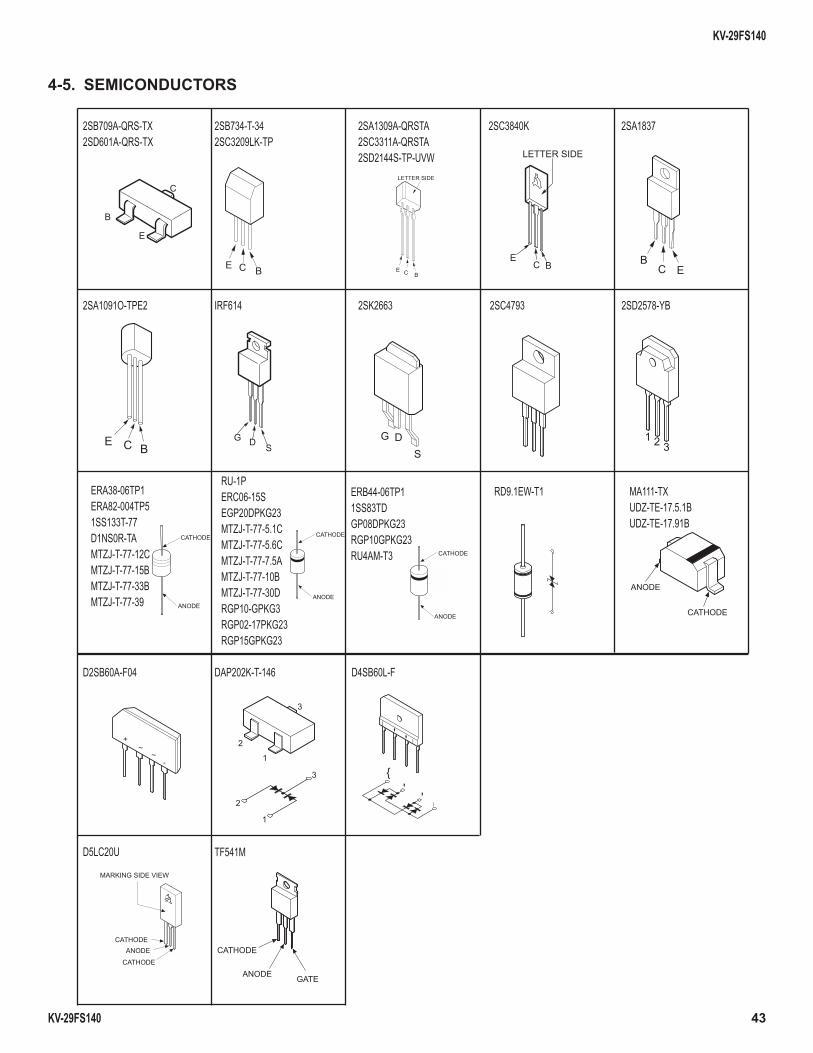
KV-29FS140
KV-29FS140 43
2SB709A-QRS-TX2SD601A-QRS-TX
2SB734-T-342SC3209LK-TP
2SA1837
2SA1091O-TPE2
2SA1309A-QRSTA2SC3311A-QRSTA2SD2144S-TP-UVW
2SC3840K
IRF614 2SK2663 2SD2578-YB2SC4793
ERB44-06TP11SS83TDGP08DPKG23RGP10GPKG23RU4AM-T3
RD9.1EW-T1 MA111-TX UDZ-TE-17.5.1B UDZ-TE-17.91B
D2SB60A-F04 DAP202K-T-146 D4SB60L-F
D5LC20U
E
B
C
BCE
LETTER SIDE
E C B
LETTER SIDE
EC B B
C E
E C BG D S
DG
S1 2 3
CATHODE
ANODE
ERA38-06TP1ERA82-004TP51SS133T-77D1NS0R-TAMTZJ-T-77-12CMTZJ-T-77-15BMTZJ-T-77-33BMTZJ-T-77-39
CATHODE
ANODE
CATHODE
ANODE
ANODE
CATHODE
+~
-~ 1
2
3
1
2
3 '
'
' '
MARKING SIDE VIEW
CATHODEANODE
CATHODE
CATHODE
ANODE GATE
TF541M
RU-1PERC06-15SEGP20DPKG23MTZJ-T-77-5.1CMTZJ-T-77-5.6CMTZJ-T-77-7.5AMTZJ-T-77-10BMTZJ-T-77-30DRGP10-GPKG3RGP02-17PKG23RGP15GPKG23
4-5. SEMICONDUCTORS
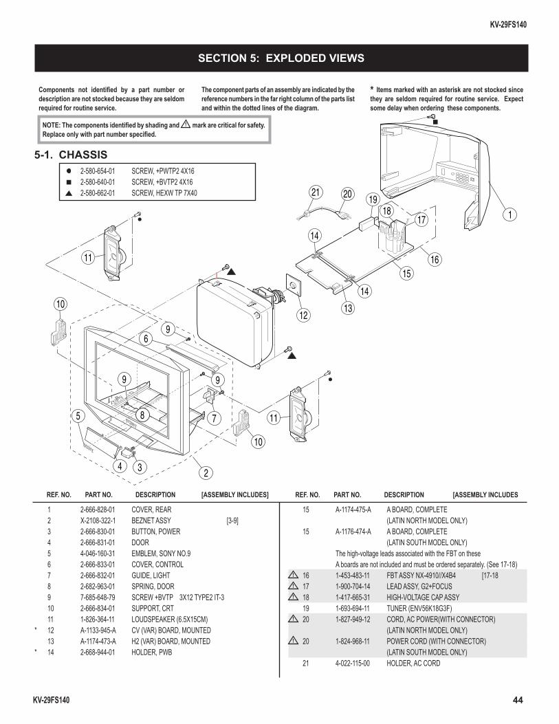
44
KV-29FS140
KV-29FS140
Components not identifi ed by a part number or description are not stocked because they are seldom required for routine service.
NOTE: The components identifi ed by shading and ! mark are critical for safety. Replace only with part number specifi ed.
The component parts of an assembly are indicated by the reference numbers in the far right column of the parts list and within the dotted lines of the diagram.
* Items marked with an asterisk are not stocked since they are seldom required for routine service. Expect some delay when ordering these components.
2-580-654-01 SCREW, +PWTP2 4X16 2-580-640-01 SCREW, +BVTP2 4X16 2-580-662-01 SCREW, HEXW TP 7X40
1 2-666-828-01 COVER, REAR 2 X-2108-322-1 BEZNET ASSY [3-9] 3 2-666-830-01 BUTTON, POWER 4 2-666-831-01 DOOR 5 4-046-160-31 EMBLEM, SONY NO.9 6 2-666-833-01 COVER, CONTROL 7 2-666-832-01 GUIDE, LIGHT 8 2-682-963-01 SPRING, DOOR 9 7-685-648-79 SCREW +BVTP 3X12 TYPE2 IT-3 10 2-666-834-01 SUPPORT, CRT 11 1-826-364-11 LOUDSPEAKER (6.5X15CM) * 12 A-1133-945-A CV (VAR) BOARD, MOUNTED 13 A-1174-473-A H2 (VAR) BOARD, MOUNTED * 14 2-668-944-01 HOLDER, PWB
15 A-1174-475-A A BOARD, COMPLETE (LATIN NORTH MODEL ONLY) 15 A-1176-474-A A BOARD, COMPLETE (LATIN SOUTH MODEL ONLY) The high-voltage leads associated with the FBT on these A boards are not included and must be ordered separately. (See 17-18)
! 16 1-453-483-11 FBT ASSY NX-4910//X4B4 [17-18! 17 1-900-704-14 LEAD ASSY, G2+FOCUS! 18 1-417-665-31 HIGH-VOLTAGE CAP ASSY
19 1-693-694-11 TUNER (ENV56K18G3F)! 20 1-827-949-12 CORD, AC POWER(WITH CONNECTOR)
(LATIN NORTH MODEL ONLY)! 20 1-824-968-11 POWER CORD (WITH CONNECTOR)
(LATIN SOUTH MODEL ONLY) 21 4-022-115-00 HOLDER, AC CORD
5-1. CHASSIS
SECTION 5: EXPLODED VIEWS
REF. NO. PART NO. DESCRIPTION [ASSEMBLY INCLUDES] REF. NO. PART NO. DESCRIPTION [ASSEMBLY INCLUDES
342
1
10
10
6
7 11
11
5 8
9
9
9
19
1516
1312
14
14
1718
21 20
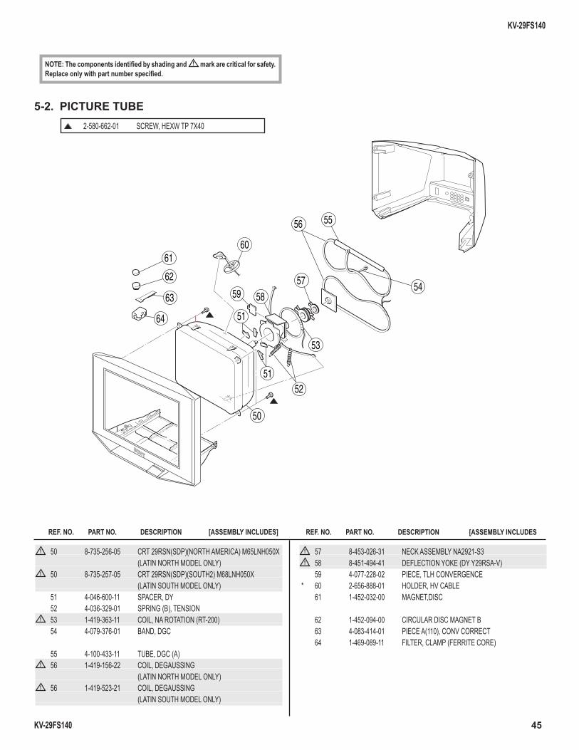
45
KV-29FS140
KV-29FS140
REF. NO. PART NO. DESCRIPTION [ASSEMBLY INCLUDES] REF. NO. PART NO. DESCRIPTION [ASSEMBLY INCLUDES
NOTE: The components identifi ed by shading and ! mark are critical for safety. Replace only with part number specifi ed.
! 50 8-735-256-05 CRT 29RSN(SDP)(NORTH AMERICA) M65LNH050X (LATIN NORTH MODEL ONLY)
! 50 8-735-257-05 CRT 29RSN(SDP)(SOUTH2) M68LNH050X (LATIN SOUTH MODEL ONLY) 51 4-046-600-11 SPACER, DY 52 4-036-329-01 SPRING (B), TENSION
! 53 1-419-363-11 COIL, NA ROTATION (RT-200) 54 4-079-376-01 BAND, DGC
55 4-100-433-11 TUBE, DGC (A)! 56 1-419-156-22 COIL, DEGAUSSING
(LATIN NORTH MODEL ONLY)! 56 1-419-523-21 COIL, DEGAUSSING
(LATIN SOUTH MODEL ONLY)
2-580-662-01 SCREW, HEXW TP 7X40
5-2. PICTURE TUBE
! 57 8-453-026-31 NECK ASSEMBLY NA2921-S3! 58 8-451-494-41 DEFLECTION YOKE (DY Y29RSA-V)
59 4-077-228-02 PIECE, TLH CONVERGENCE * 60 2-656-888-01 HOLDER, HV CABLE 61 1-452-032-00 MAGNET,DISC
62 1-452-094-00 CIRCULAR DISC MAGNET B 63 4-083-414-01 PIECE A(110), CONV CORRECT 64 1-469-089-11 FILTER, CLAMP (FERRITE CORE)
59
50
5152
53
54
5556
57
51
5863
64
61
62
60
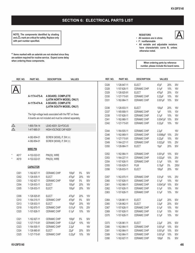
KV-29FS140
KV-29FS140 46
* Items marked with an asterisk are not stocked since they are seldom required for routine service. Expect some delay when ordering these components.
RESISTORS• All resistors are in ohms• F : nonfl ammable• All variable and adjustable resistors
have characteristic curve B, unless otherwise noted.
REF. NO. PART NO. DESCRIPTION VALUES
When ordering parts by referencenumber, please include the board name.
A
REF. NO. PART NO. DESCRIPTION VALUES
NOTE: The components identifi ed by shading and ! mark are critical for safety. Replace only with part number specifi ed.
SECTION 6: ELECTRICAL PARTS LIST
A A-1174-475-A A BOARD, COMPLETE (LATIN NORTH MODEL ONLY) A-1176-474-A A BOARD, COMPLETE (LATIN SOUTH MODEL ONLY)
The high-voltage leads associated with the FBT on these A boards are not included and must be ordered separately.
! 1-900-704-14 LEAD ASSY, G2+FOCUS! 1-417-665-31 HIGH-VOLTAGE CAP ASSY
4-382-854-01 SCREW (M3X8), P, SW (+) 4-382-854-01 SCREW (M3X8), P, SW (+)
WIRE PIN
* A017 4-102-022-01 PIN(30), WIRE* A019 4-102-022-01 PIN(30), WIRE
CAPACITOR
C001 1-162-927-11 CERAMIC CHIP 100pF 5% 50V C002 1-126-935-11 ELECT 470µF 20% 16V C003 1-162-927-11 CERAMIC CHIP 100pF 5% 50V C004 1-126-933-11 ELECT 100µF 20% 16V C005 1-126-933-11 ELECT 100µF 20% 16V C006 1-126-925-91 ELECT 470µF 20% 10V C010 1-164-315-11 CERAMIC CHIP 470pF 5% 50V C013 1-126-933-11 ELECT 100µF 20% 16V C018 1-162-970-11 CERAMIC CHIP 0.01µF 10% 25V C020 1-107-826-11 CERAMIC CHIP 0.1µF 10% 16V C021 1-162-927-11 CERAMIC CHIP 100pF 5% 50V C022 1-127-715-91 CERAMIC CHIP 0.22µF 10% 16V C023 1-164-505-11 CERAMIC CHIP 2.2µF 16V C024 1-126-965-91 ELECT 22µF 20% 50V C025 1-127-715-91 CERAMIC CHIP 0.22µF 10% 16V
C026 1-126-947-11 ELECT 47µF 20% 35V C028 1-107-826-11 CERAMIC CHIP 0.1µF 10% 16V C029 1-126-925-91 ELECT 470µF 20% 10V C030 1-127-715-91 CERAMIC CHIP 0.22µF 10% 16V C031 1-162-964-11 CERAMIC CHIP 0.001µF 10% 50V C036 1-126-933-11 ELECT 100µF 20% 16V C037 1-165-908-11 CERAMIC CHIP 1µF 10% 10V C038 1-107-826-11 CERAMIC CHIP 0.1µF 10% 16V C041 1-162-968-11 CERAMIC CHIP 0.0047µF 10% 50V C042 1-127-715-91 CERAMIC CHIP 0.22µF 10% 16V C044 1-164-505-11 CERAMIC CHIP 2.2µF 16V C046 1-162-969-11 CERAMIC CHIP 0.0068µF 10% 25V C048 1-127-715-91 CERAMIC CHIP 0.22µF 10% 16V C049 1-164-227-11 CERAMIC CHIP 0.022µF 10% 25V C050 1-126-964-11 ELECT 10µF 20% 50V C052 1-162-964-11 CERAMIC CHIP 0.001µF 10% 50V C053 1-164-227-11 CERAMIC CHIP 0.022µF 10% 25V C054 1-107-826-11 CERAMIC CHIP 0.1µF 10% 16V C055 1-100-829-11 FILM 0.15µF 5% 250V C056 1-126-933-11 ELECT 100µF 20% 16V C057 1-162-970-11 CERAMIC CHIP 0.01µF 10% 25V C060 1-107-826-11 CERAMIC CHIP 0.1µF 10% 16V C061 1-162-968-11 CERAMIC CHIP 0.0047µF 10% 50V C062 1-107-826-11 CERAMIC CHIP 0.1µF 10% 16V C063 1-107-826-11 CERAMIC CHIP 0.1µF 10% 16V C064 1-126-961-11 ELECT 2.2µF 20% 50V C065 1-126-962-11 ELECT 3.3µF 20% 50V C067 1-107-826-11 CERAMIC CHIP 0.1µF 10% 16V C069 1-107-826-11 CERAMIC CHIP 0.1µF 10% 16V C070 1-107-826-11 CERAMIC CHIP 0.1µF 10% 16V C073 1-126-961-11 ELECT 2.2µF 20% 50V C080 1-162-964-11 CERAMIC CHIP 0.001µF 10% 50V C081 1-162-964-11 CERAMIC CHIP 0.001µF 10% 50V C089 1-162-964-11 CERAMIC CHIP 0.001µF 10% 50V C090 1-162-927-11 CERAMIC CHIP 100pF 5% 50V
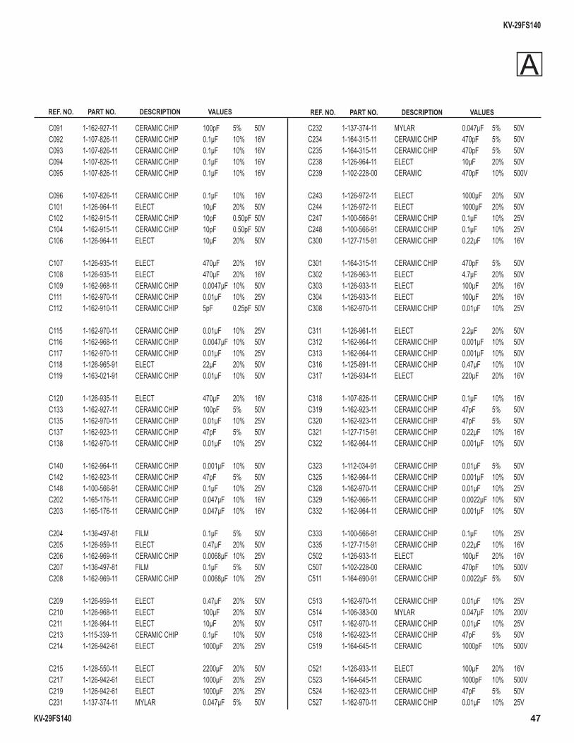
KV-29FS140
KV-29FS140 47
REF. NO. PART NO. DESCRIPTION VALUES REF. NO. PART NO. DESCRIPTION VALUES
C091 1-162-927-11 CERAMIC CHIP 100pF 5% 50V C092 1-107-826-11 CERAMIC CHIP 0.1µF 10% 16V C093 1-107-826-11 CERAMIC CHIP 0.1µF 10% 16V C094 1-107-826-11 CERAMIC CHIP 0.1µF 10% 16V C095 1-107-826-11 CERAMIC CHIP 0.1µF 10% 16V
C096 1-107-826-11 CERAMIC CHIP 0.1µF 10% 16V C101 1-126-964-11 ELECT 10µF 20% 50V C102 1-162-915-11 CERAMIC CHIP 10pF 0.50pF 50V C104 1-162-915-11 CERAMIC CHIP 10pF 0.50pF 50V C106 1-126-964-11 ELECT 10µF 20% 50V C107 1-126-935-11 ELECT 470µF 20% 16V C108 1-126-935-11 ELECT 470µF 20% 16V C109 1-162-968-11 CERAMIC CHIP 0.0047µF 10% 50V C111 1-162-970-11 CERAMIC CHIP 0.01µF 10% 25V C112 1-162-910-11 CERAMIC CHIP 5pF 0.25pF 50V
C115 1-162-970-11 CERAMIC CHIP 0.01µF 10% 25V C116 1-162-968-11 CERAMIC CHIP 0.0047µF 10% 50V C117 1-162-970-11 CERAMIC CHIP 0.01µF 10% 25V C118 1-126-965-91 ELECT 22µF 20% 50V C119 1-163-021-91 CERAMIC CHIP 0.01µF 10% 50V C120 1-126-935-11 ELECT 470µF 20% 16V C133 1-162-927-11 CERAMIC CHIP 100pF 5% 50V C135 1-162-970-11 CERAMIC CHIP 0.01µF 10% 25V C137 1-162-923-11 CERAMIC CHIP 47pF 5% 50V C138 1-162-970-11 CERAMIC CHIP 0.01µF 10% 25V C140 1-162-964-11 CERAMIC CHIP 0.001µF 10% 50V C142 1-162-923-11 CERAMIC CHIP 47pF 5% 50V C148 1-100-566-91 CERAMIC CHIP 0.1µF 10% 25V C202 1-165-176-11 CERAMIC CHIP 0.047µF 10% 16V C203 1-165-176-11 CERAMIC CHIP 0.047µF 10% 16V C204 1-136-497-81 FILM 0.1µF 5% 50V C205 1-126-959-11 ELECT 0.47µF 20% 50V C206 1-162-969-11 CERAMIC CHIP 0.0068µF 10% 25V C207 1-136-497-81 FILM 0.1µF 5% 50V C208 1-162-969-11 CERAMIC CHIP 0.0068µF 10% 25V C209 1-126-959-11 ELECT 0.47µF 20% 50V C210 1-126-968-11 ELECT 100µF 20% 50V C211 1-126-964-11 ELECT 10µF 20% 50V C213 1-115-339-11 CERAMIC CHIP 0.1µF 10% 50V C214 1-126-942-61 ELECT 1000µF 20% 25V C215 1-128-550-11 ELECT 2200µF 20% 50V C217 1-126-942-61 ELECT 1000µF 20% 25V C219 1-126-942-61 ELECT 1000µF 20% 25V C231 1-137-374-11 MYLAR 0.047µF 5% 50V
C232 1-137-374-11 MYLAR 0.047µF 5% 50V C234 1-164-315-11 CERAMIC CHIP 470pF 5% 50V C235 1-164-315-11 CERAMIC CHIP 470pF 5% 50V C238 1-126-964-11 ELECT 10µF 20% 50V C239 1-102-228-00 CERAMIC 470pF 10% 500V
C243 1-126-972-11 ELECT 1000µF 20% 50V C244 1-126-972-11 ELECT 1000µF 20% 50V C247 1-100-566-91 CERAMIC CHIP 0.1µF 10% 25V C248 1-100-566-91 CERAMIC CHIP 0.1µF 10% 25V C300 1-127-715-91 CERAMIC CHIP 0.22µF 10% 16V
C301 1-164-315-11 CERAMIC CHIP 470pF 5% 50V C302 1-126-963-11 ELECT 4.7µF 20% 50V C303 1-126-933-11 ELECT 100µF 20% 16V C304 1-126-933-11 ELECT 100µF 20% 16V C308 1-162-970-11 CERAMIC CHIP 0.01µF 10% 25V
C311 1-126-961-11 ELECT 2.2µF 20% 50V C312 1-162-964-11 CERAMIC CHIP 0.001µF 10% 50V C313 1-162-964-11 CERAMIC CHIP 0.001µF 10% 50V C316 1-125-891-11 CERAMIC CHIP 0.47µF 10% 10V C317 1-126-934-11 ELECT 220µF 20% 16V
C318 1-107-826-11 CERAMIC CHIP 0.1µF 10% 16V C319 1-162-923-11 CERAMIC CHIP 47pF 5% 50V C320 1-162-923-11 CERAMIC CHIP 47pF 5% 50V C321 1-127-715-91 CERAMIC CHIP 0.22µF 10% 16V C322 1-162-964-11 CERAMIC CHIP 0.001µF 10% 50V
C323 1-112-034-91 CERAMIC CHIP 0.01µF 5% 50V C325 1-162-964-11 CERAMIC CHIP 0.001µF 10% 50V C328 1-162-970-11 CERAMIC CHIP 0.01µF 10% 25V C329 1-162-966-11 CERAMIC CHIP 0.0022µF 10% 50V C332 1-162-964-11 CERAMIC CHIP 0.001µF 10% 50V
C333 1-100-566-91 CERAMIC CHIP 0.1µF 10% 25V C335 1-127-715-91 CERAMIC CHIP 0.22µF 10% 16V C502 1-126-933-11 ELECT 100µF 20% 16V C507 1-102-228-00 CERAMIC 470pF 10% 500V C511 1-164-690-91 CERAMIC CHIP 0.0022µF 5% 50V
C513 1-162-970-11 CERAMIC CHIP 0.01µF 10% 25V C514 1-106-383-00 MYLAR 0.047µF 10% 200V C517 1-162-970-11 CERAMIC CHIP 0.01µF 10% 25V C518 1-162-923-11 CERAMIC CHIP 47pF 5% 50V C519 1-164-645-11 CERAMIC 1000pF 10% 500V
C521 1-126-933-11 ELECT 100µF 20% 16V C523 1-164-645-11 CERAMIC 1000pF 10% 500V C524 1-162-923-11 CERAMIC CHIP 47pF 5% 50V C527 1-162-970-11 CERAMIC CHIP 0.01µF 10% 25V
A
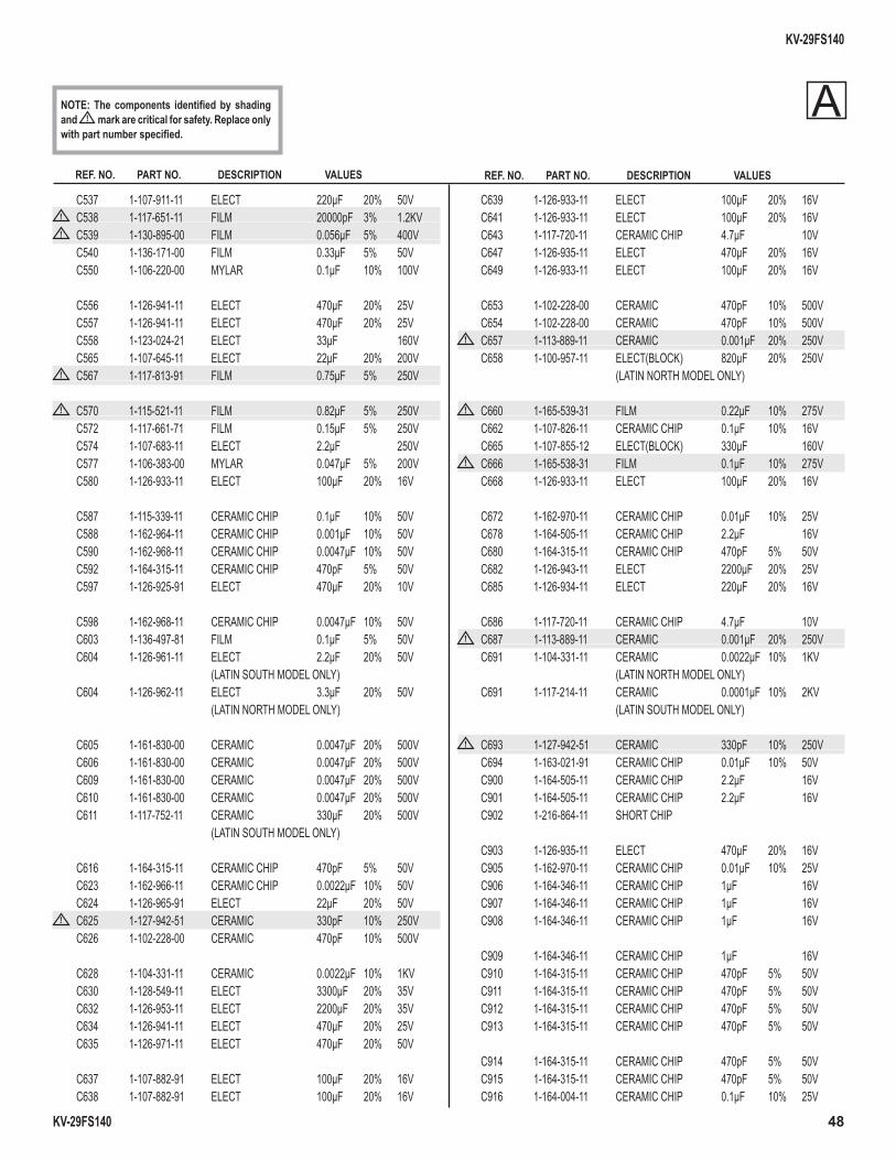
KV-29FS140
KV-29FS140 48
REF. NO. PART NO. DESCRIPTION VALUES REF. NO. PART NO. DESCRIPTION VALUES
NOTE: The components identifi ed by shading and ! mark are critical for safety. Replace only with part number specifi ed.
C537 1-107-911-11 ELECT 220µF 20% 50V! C538 1-117-651-11 FILM 20000pF 3% 1.2KV! C539 1-130-895-00 FILM 0.056µF 5% 400V
C540 1-136-171-00 FILM 0.33µF 5% 50V C550 1-106-220-00 MYLAR 0.1µF 10% 100V
C556 1-126-941-11 ELECT 470µF 20% 25V C557 1-126-941-11 ELECT 470µF 20% 25V C558 1-123-024-21 ELECT 33µF 160V C565 1-107-645-11 ELECT 22µF 20% 200V
! C567 1-117-813-91 FILM 0.75µF 5% 250V
! C570 1-115-521-11 FILM 0.82µF 5% 250V C572 1-117-661-71 FILM 0.15µF 5% 250V C574 1-107-683-11 ELECT 2.2µF 250V C577 1-106-383-00 MYLAR 0.047µF 5% 200V C580 1-126-933-11 ELECT 100µF 20% 16V
C587 1-115-339-11 CERAMIC CHIP 0.1µF 10% 50V C588 1-162-964-11 CERAMIC CHIP 0.001µF 10% 50V C590 1-162-968-11 CERAMIC CHIP 0.0047µF 10% 50V C592 1-164-315-11 CERAMIC CHIP 470pF 5% 50V C597 1-126-925-91 ELECT 470µF 20% 10V
C598 1-162-968-11 CERAMIC CHIP 0.0047µF 10% 50V C603 1-136-497-81 FILM 0.1µF 5% 50V C604 1-126-961-11 ELECT 2.2µF 20% 50V (LATIN SOUTH MODEL ONLY) C604 1-126-962-11 ELECT 3.3µF 20% 50V (LATIN NORTH MODEL ONLY)
C605 1-161-830-00 CERAMIC 0.0047µF 20% 500V C606 1-161-830-00 CERAMIC 0.0047µF 20% 500V C609 1-161-830-00 CERAMIC 0.0047µF 20% 500V C610 1-161-830-00 CERAMIC 0.0047µF 20% 500V C611 1-117-752-11 CERAMIC 330µF 20% 500V (LATIN SOUTH MODEL ONLY)
C616 1-164-315-11 CERAMIC CHIP 470pF 5% 50V C623 1-162-966-11 CERAMIC CHIP 0.0022µF 10% 50V C624 1-126-965-91 ELECT 22µF 20% 50V
! C625 1-127-942-51 CERAMIC 330pF 10% 250V C626 1-102-228-00 CERAMIC 470pF 10% 500V C628 1-104-331-11 CERAMIC 0.0022µF 10% 1KV C630 1-128-549-11 ELECT 3300µF 20% 35V C632 1-126-953-11 ELECT 2200µF 20% 35V C634 1-126-941-11 ELECT 470µF 20% 25V C635 1-126-971-11 ELECT 470µF 20% 50V C637 1-107-882-91 ELECT 100µF 20% 16V C638 1-107-882-91 ELECT 100µF 20% 16V
C639 1-126-933-11 ELECT 100µF 20% 16V C641 1-126-933-11 ELECT 100µF 20% 16V C643 1-117-720-11 CERAMIC CHIP 4.7µF 10V C647 1-126-935-11 ELECT 470µF 20% 16V C649 1-126-933-11 ELECT 100µF 20% 16V
C653 1-102-228-00 CERAMIC 470pF 10% 500V C654 1-102-228-00 CERAMIC 470pF 10% 500V
! C657 1-113-889-11 CERAMIC 0.001µF 20% 250V C658 1-100-957-11 ELECT(BLOCK) 820µF 20% 250V (LATIN NORTH MODEL ONLY)
! C660 1-165-539-31 FILM 0.22µF 10% 275V C662 1-107-826-11 CERAMIC CHIP 0.1µF 10% 16V C665 1-107-855-12 ELECT(BLOCK) 330µF 160V
! C666 1-165-538-31 FILM 0.1µF 10% 275V C668 1-126-933-11 ELECT 100µF 20% 16V
C672 1-162-970-11 CERAMIC CHIP 0.01µF 10% 25V C678 1-164-505-11 CERAMIC CHIP 2.2µF 16V C680 1-164-315-11 CERAMIC CHIP 470pF 5% 50V C682 1-126-943-11 ELECT 2200µF 20% 25V C685 1-126-934-11 ELECT 220µF 20% 16V
C686 1-117-720-11 CERAMIC CHIP 4.7µF 10V ! C687 1-113-889-11 CERAMIC 0.001µF 20% 250V
C691 1-104-331-11 CERAMIC 0.0022µF 10% 1KV (LATIN NORTH MODEL ONLY) C691 1-117-214-11 CERAMIC 0.0001µF 10% 2KV (LATIN SOUTH MODEL ONLY)
! C693 1-127-942-51 CERAMIC 330pF 10% 250V C694 1-163-021-91 CERAMIC CHIP 0.01µF 10% 50V C900 1-164-505-11 CERAMIC CHIP 2.2µF 16V C901 1-164-505-11 CERAMIC CHIP 2.2µF 16V C902 1-216-864-11 SHORT CHIP
C903 1-126-935-11 ELECT 470µF 20% 16V C905 1-162-970-11 CERAMIC CHIP 0.01µF 10% 25V C906 1-164-346-11 CERAMIC CHIP 1µF 16V C907 1-164-346-11 CERAMIC CHIP 1µF 16V C908 1-164-346-11 CERAMIC CHIP 1µF 16V
C909 1-164-346-11 CERAMIC CHIP 1µF 16V C910 1-164-315-11 CERAMIC CHIP 470pF 5% 50V C911 1-164-315-11 CERAMIC CHIP 470pF 5% 50V C912 1-164-315-11 CERAMIC CHIP 470pF 5% 50V C913 1-164-315-11 CERAMIC CHIP 470pF 5% 50V
C914 1-164-315-11 CERAMIC CHIP 470pF 5% 50V C915 1-164-315-11 CERAMIC CHIP 470pF 5% 50V C916 1-164-004-11 CERAMIC CHIP 0.1µF 10% 25V
A
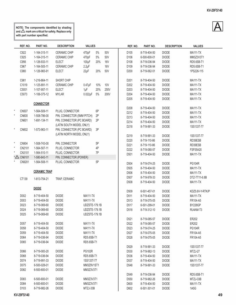
KV-29FS140
KV-29FS140 49
REF. NO. PART NO. DESCRIPTION VALUES REF. NO. PART NO. DESCRIPTION VALUES
NOTE: The components identifi ed by shading and ! mark are critical for safety. Replace only with part number specifi ed.
C922 1-164-315-11 CERAMIC CHIP 470pF 5% 50V C925 1-164-315-11 CERAMIC CHIP 470pF 5% 50V C956 1-126-933-11 ELECT 100µF 20% 16V C967 1-164-505-11 CERAMIC CHIP 2.2µF 16V C980 1-126-965-91 ELECT 22µF 20% 50V
C981 1-216-864-11 SHORT CHIP C1019 1-125-891-11 CERAMIC CHIP 0.47µF 10% 10V C5001 1-107-957-11 ELECT 1µF 20% 250V C5073 1-106-375-12 MYLAR 0.022µF 5% 200V
CONNECTOR
* CN507 1-564-509-11 PLUG, CONNECTOR 6P * CN600 1-508-786-00 PIN, CONNECTOR (5MM PITCH) 2P CN601 1-691-134-11 PIN, CONNECTOR (PC BOARD) 2P (LATIN SOUTH MODEL ONLY)* CN602 1-573-963-11 PIN, CONNECTOR (PC BOARD) 3P (LATIN NORTH MODEL ONLY)
* CN904 1-508-743-00 PIN, CONNECTOR 5P * CN2101 1-564-507-11 PLUG, CONNECTOR 4P * CN3101 1-564-510-11 PLUG, CONNECTOR 7P * ! CN6101 1-580-843-11 PIN, CONNECTOR (POWER) * CN9201 1-564-508-11 PLUG, CONNECTOR 5P
CERAMIC TRAP
CT139 1-813-754-21 TRAP, CERAMIC
DIODE
D002 8-719-404-50 DIODE MA111-TX D003 8-719-404-50 DIODE MA111-TX D023 8-719-069-60 DIODE UDZSTE-179.1B D024 8-719-069-60 DIODE UDZSTE-179.1B D025 8-719-069-60 DIODE UDZSTE-179.1B
D057 8-719-404-50 DIODE MA111-TX D058 8-719-404-50 DIODE MA111-TX D059 8-719-404-50 DIODE MA111-TX D064 8-719-036-94 DIODE RD5.6SB-T1 D065 8-719-036-94 DIODE RD5.6SB-T1
D066 8-719-083-20 DIODE PG102R D068 8-719-036-94 DIODE RD5.6SB-T1 D074 8-719-991-33 DIODE 1SS133T-77 D075 6-500-028-01 DIODE MM3Z9V1ST1 D082 6-500-600-01 DIODE MM3Z3V3T1
D083 6-500-600-01 DIODE MM3Z3V3T1 D084 6-500-600-01 DIODE MM3Z3V3T1 D103 8-719-982-26 DIODE MTZJ-33B
D105 8-719-404-50 DIODE MA111-TX D106 6-500-600-01 DIODE MM3Z3V3T1 D108 8-719-036-94 DIODE RD5.6SB-T1 D109 8-719-036-94 DIODE RD5.6SB-T1 D200 8-719-062-51 DIODE 1PS226-115
D201 8-719-404-50 DIODE MA111-TX D202 8-719-404-50 DIODE MA111-TX D203 8-719-404-50 DIODE MA111-TX D204 8-719-404-50 DIODE MA111-TX D205 8-719-404-50 DIODE MA111-TX
D208 8-719-404-50 DIODE MA111-TX D212 8-719-404-50 DIODE MA111-TX D213 8-719-404-50 DIODE MA111-TX D214 8-719-404-50 DIODE MA111-TX D218 8-719-991-33 DIODE 1SS133T-77
D219 8-719-991-33 DIODE 1SS133T-77 D220 8-719-110-86 DIODE RD39ESB D221 8-719-110-86 DIODE RD39ESB D222 8-719-080-57 DIODE FSF05A20 D501 8-719-404-50 DIODE MA111-TX
D504 8-719-074-25 DIODE PG104R D505 8-719-404-50 DIODE MA111-TX D506 8-719-404-50 DIODE MA111-TX D507 8-719-978-33 DIODE DTZ-TT11-6.8B D508 8-719-404-50 DIODE MA111-TX
D509 6-501-457-01 DIODE KDZ5.6V-Y-RTK/P D511 8-719-404-50 DIODE MA111-TX D513 8-719-075-05 DIODE FR104-A5 D517 6-501-299-01 DIODE BY228GP D518 8-719-312-10 DIODE RU4AM-T3
D521 8-719-085-57 DIODE ER202 D522 8-719-085-57 DIODE ER202 D523 8-719-074-25 DIODE PG104R D527 8-719-075-05 DIODE FR104-A5 D528 8-719-075-05 DIODE FR104-A5
D529 8-719-991-33 DIODE 1SS133T-77 D530 8-719-982-13 DIODE MTZJ-27 D536 8-719-404-50 DIODE MA111-TX D537 8-719-404-50 DIODE MA111-TX D548 8-719-991-33 DIODE 1SS133T-77
D549 8-719-036-94 DIODE RD5.6SB-T1 D550 8-719-982-26 DIODE MTZJ-33B D600 8-719-404-50 DIODE MA111-TX D602 6-501-301-01 DIODE 1A5G
A
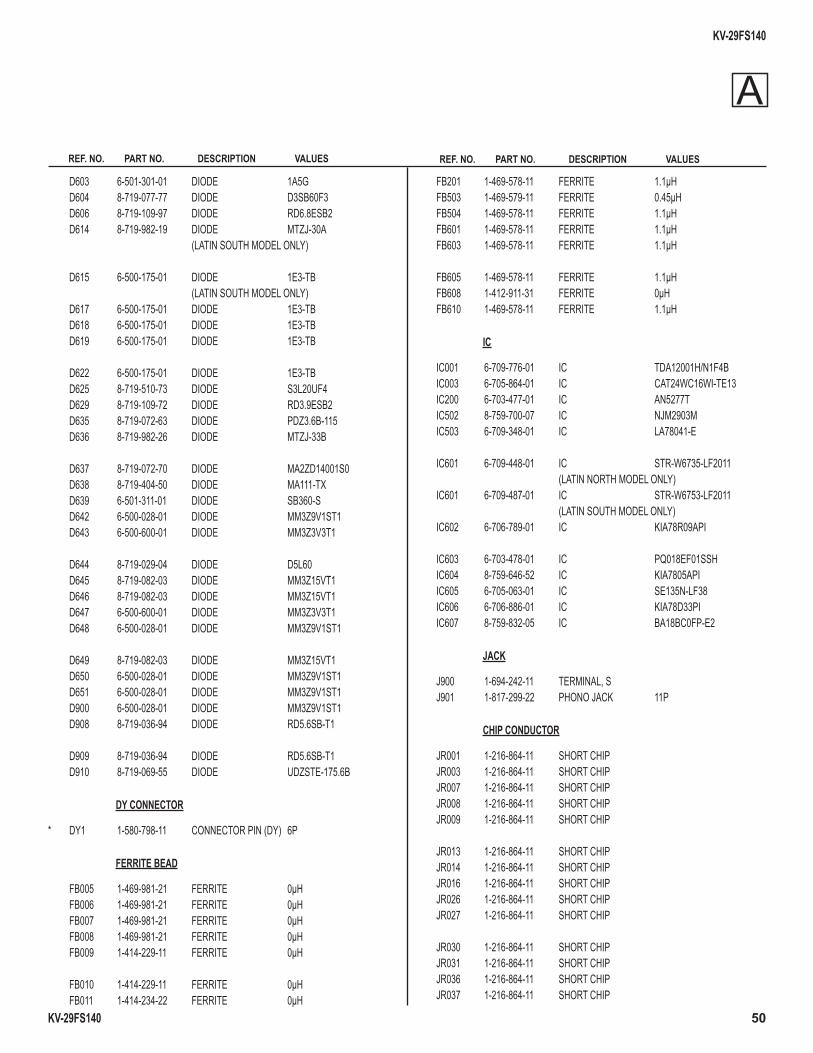
KV-29FS140
KV-29FS140 50
REF. NO. PART NO. DESCRIPTION VALUES REF. NO. PART NO. DESCRIPTION VALUES
D603 6-501-301-01 DIODE 1A5G D604 8-719-077-77 DIODE D3SB60F3 D606 8-719-109-97 DIODE RD6.8ESB2 D614 8-719-982-19 DIODE MTZJ-30A (LATIN SOUTH MODEL ONLY)
D615 6-500-175-01 DIODE 1E3-TB (LATIN SOUTH MODEL ONLY) D617 6-500-175-01 DIODE 1E3-TB D618 6-500-175-01 DIODE 1E3-TB D619 6-500-175-01 DIODE 1E3-TB
D622 6-500-175-01 DIODE 1E3-TB D625 8-719-510-73 DIODE S3L20UF4 D629 8-719-109-72 DIODE RD3.9ESB2 D635 8-719-072-63 DIODE PDZ3.6B-115 D636 8-719-982-26 DIODE MTZJ-33B
D637 8-719-072-70 DIODE MA2ZD14001S0 D638 8-719-404-50 DIODE MA111-TX D639 6-501-311-01 DIODE SB360-S D642 6-500-028-01 DIODE MM3Z9V1ST1 D643 6-500-600-01 DIODE MM3Z3V3T1
D644 8-719-029-04 DIODE D5L60 D645 8-719-082-03 DIODE MM3Z15VT1 D646 8-719-082-03 DIODE MM3Z15VT1 D647 6-500-600-01 DIODE MM3Z3V3T1 D648 6-500-028-01 DIODE MM3Z9V1ST1
D649 8-719-082-03 DIODE MM3Z15VT1 D650 6-500-028-01 DIODE MM3Z9V1ST1 D651 6-500-028-01 DIODE MM3Z9V1ST1 D900 6-500-028-01 DIODE MM3Z9V1ST1 D908 8-719-036-94 DIODE RD5.6SB-T1
D909 8-719-036-94 DIODE RD5.6SB-T1 D910 8-719-069-55 DIODE UDZSTE-175.6B
DY CONNECTOR
* DY1 1-580-798-11 CONNECTOR PIN (DY) 6P
FERRITE BEAD
FB005 1-469-981-21 FERRITE 0µH FB006 1-469-981-21 FERRITE 0µH FB007 1-469-981-21 FERRITE 0µH FB008 1-469-981-21 FERRITE 0µH FB009 1-414-229-11 FERRITE 0µH
FB010 1-414-229-11 FERRITE 0µH FB011 1-414-234-22 FERRITE 0µH
FB201 1-469-578-11 FERRITE 1.1µH FB503 1-469-579-11 FERRITE 0.45µH FB504 1-469-578-11 FERRITE 1.1µH FB601 1-469-578-11 FERRITE 1.1µH FB603 1-469-578-11 FERRITE 1.1µH
FB605 1-469-578-11 FERRITE 1.1µH FB608 1-412-911-31 FERRITE 0µH FB610 1-469-578-11 FERRITE 1.1µH
IC
IC001 6-709-776-01 IC TDA12001H/N1F4B IC003 6-705-864-01 IC CAT24WC16WI-TE13 IC200 6-703-477-01 IC AN5277T IC502 8-759-700-07 IC NJM2903M IC503 6-709-348-01 IC LA78041-E
IC601 6-709-448-01 IC STR-W6735-LF2011 (LATIN NORTH MODEL ONLY) IC601 6-709-487-01 IC STR-W6753-LF2011 (LATIN SOUTH MODEL ONLY) IC602 6-706-789-01 IC KIA78R09API
IC603 6-703-478-01 IC PQ018EF01SSH IC604 8-759-646-52 IC KIA7805API IC605 6-705-063-01 IC SE135N-LF38 IC606 6-706-886-01 IC KIA78D33PI IC607 8-759-832-05 IC BA18BC0FP-E2
JACK
J900 1-694-242-11 TERMINAL, S J901 1-817-299-22 PHONO JACK 11P
CHIP CONDUCTOR
JR001 1-216-864-11 SHORT CHIP JR003 1-216-864-11 SHORT CHIP JR007 1-216-864-11 SHORT CHIP JR008 1-216-864-11 SHORT CHIP JR009 1-216-864-11 SHORT CHIP JR013 1-216-864-11 SHORT CHIP JR014 1-216-864-11 SHORT CHIP JR016 1-216-864-11 SHORT CHIP JR026 1-216-864-11 SHORT CHIP JR027 1-216-864-11 SHORT CHIP JR030 1-216-864-11 SHORT CHIP JR031 1-216-864-11 SHORT CHIP JR036 1-216-864-11 SHORT CHIP JR037 1-216-864-11 SHORT CHIP
A
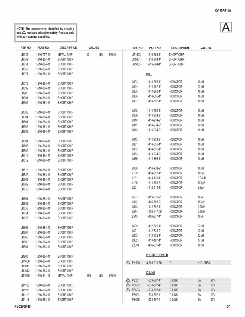
KV-29FS140
KV-29FS140 51
REF. NO. PART NO. DESCRIPTION VALUES REF. NO. PART NO. DESCRIPTION VALUES
NOTE: The components identifi ed by shading and ! mark are critical for safety. Replace only with part number specifi ed.
JR042 1-216-797-11 METAL CHIP 10 5% 1/10W JR049 1-216-864-11 SHORT CHIP JR051 1-216-864-11 SHORT CHIP JR052 1-216-864-11 SHORT CHIP JR071 1-216-864-11 SHORT CHIP
JR072 1-216-864-11 SHORT CHIP JR099 1-216-864-11 SHORT CHIP JR203 1-216-864-11 SHORT CHIP JR301 1-216-864-11 SHORT CHIP JR302 1-216-864-11 SHORT CHIP
JR303 1-216-864-11 SHORT CHIP JR304 1-216-864-11 SHORT CHIP JR501 1-216-864-11 SHORT CHIP JR502 1-216-864-11 SHORT CHIP JR503 1-216-864-11 SHORT CHIP
JR504 1-216-864-11 SHORT CHIP JR506 1-216-864-11 SHORT CHIP JR509 1-216-864-11 SHORT CHIP JR511 1-216-864-11 SHORT CHIP JR512 1-216-864-11 SHORT CHIP
JR513 1-216-864-11 SHORT CHIP JR522 1-216-864-11 SHORT CHIP JR601 1-216-864-11 SHORT CHIP JR602 1-216-864-11 SHORT CHIP JR650 1-216-864-11 SHORT CHIP
JR651 1-216-864-11 SHORT CHIP JR652 1-216-864-11 SHORT CHIP JR653 1-216-864-11 SHORT CHIP JR654 1-216-864-11 SHORT CHIP JR655 1-216-864-11 SHORT CHIP
JR666 1-216-864-11 SHORT CHIP JR667 1-216-864-11 SHORT CHIP JR668 1-216-864-11 SHORT CHIP JR800 1-216-864-11 SHORT CHIP JR801 1-216-864-11 SHORT CHIP
JR805 1-216-864-11 SHORT CHIP JR1006 1-216-864-11 SHORT CHIP JR1011 1-216-864-11 SHORT CHIP JR1012 1-216-864-11 SHORT CHIP JR1050 1-216-811-11 METAL CHIP 150 5% 1/10W
JR1100 1-216-864-11 SHORT CHIP JR1101 1-216-864-11 SHORT CHIP JR1110 1-216-864-11 SHORT CHIP JR1111 1-216-864-11 SHORT CHIP
JR1903 1-216-864-11 SHORT CHIP JR5001 1-216-864-11 SHORT CHIP JR5035 1-216-864-11 SHORT CHIP
COIL
L003 1-414-856-11 INDUCTOR 10µH L004 1-414-187-11 INDUCTOR 47µH L005 1-414-856-11 INDUCTOR 10µH L006 1-414-856-11 INDUCTOR 10µH L007 1-414-856-11 INDUCTOR 10µH
L008 1-414-856-11 INDUCTOR 10µH L009 1-414-934-21 INDUCTOR 10µH L010 1-414-934-21 INDUCTOR 10µH L011 1-414-934-21 INDUCTOR 10µH L012 1-414-934-21 INDUCTOR 10µH
L013 1-414-934-21 INDUCTOR 10µH L031 1-414-856-11 INDUCTOR 10µH L032 1-414-856-11 INDUCTOR 10µH L033 1-414-934-21 INDUCTOR 10µH L035 1-414-856-11 INDUCTOR 10µH
L036 1-414-934-21 INDUCTOR 10µH L100 1-414-857-11 INDUCTOR 100µH L101 1-414-138-11 INDUCTOR 0.33µH L106 1-414-189-31 INDUCTOR 100µH L201 1-412-519-11 INDUCTOR 3.3µH
L507 1-419-633-21 INDUCTOR 10MH L512 1-406-666-21 INDUCTOR 150µH L513 1-412-552-11 INDUCTOR 2.2MH L514 1-408-947-00 INDUCTOR 2.2MH L515 1-406-677-11 INDUCTOR 10MH
L600 1-412-529-11 INDUCTOR 22µH L601 1-412-533-21 INDUCTOR 47µH L602 1-412-529-11 INDUCTOR 22µH L902 1-414-187-11 INDUCTOR 47µH L2601 1-406-659-11 INDUCTOR 10µH
PHOTO COUPLER
! PH600 8-749-019-60 IC K1010HB01
IC LINK
! PS201 1-533-597-41 IC LINK 5A 90V! PS602 1-533-597-41 IC LINK 5A 90V! PS603 1-533-597-41 IC LINK 5A 90V
PS604 1-533-597-41 IC LINK 5A 90V PS605 1-533-597-41 IC LINK 5A 90V
A

KV-29FS140
KV-29FS140 52
REF. NO. PART NO. DESCRIPTION VALUES REF. NO. PART NO. DESCRIPTION VALUES
TRANSISTOR
Q001 8-729-038-67 TRANSISTOR KRC102S Q010 8-729-600-22 TRANSISTOR 2SA1235-F Q016 8-729-038-67 TRANSISTOR KRC102S Q018 8-729-038-67 TRANSISTOR KRC102S Q100 8-729-120-28 TRANSISTOR 2SC1623-L5L6
Q102 8-729-022-54 TRANSISTOR 2SC3779C,D-AA Q200 8-729-038-67 TRANSISTOR KRC102S Q201 8-729-600-22 TRANSISTOR 2SA1235-F Q202 8-729-600-22 TRANSISTOR 2SA1235-F Q206 8-729-038-67 TRANSISTOR KRC102S
Q501 6-550-362-01 TRANSISTOR KTA1279 Q502 8-729-140-50 TRANSISTOR 2SC3209LK Q503 8-729-120-28 TRANSISTOR 2SC1623-L5L6 Q505 6-551-406-01 TRANSISTOR IRFS614BYDTU Q506 6-551-129-01 TRANSISTOR 2SK3462
Q511 6-550-845-01 TRANSISTOR TT2142 Q512 8-729-120-28 TRANSISTOR 2SC1623-L5L6 Q513 8-729-600-22 TRANSISTOR 2SA1235-F Q515 8-729-120-28 TRANSISTOR 2SC1623-L5L6 Q516 6-550-362-01 TRANSISTOR KTA1279
Q601 8-729-120-28 TRANSISTOR 2SC1623-L5L6 Q608 8-729-120-28 TRANSISTOR 2SC1623-L5L6 Q609 8-729-120-28 TRANSISTOR 2SC1623-L5L6 Q900 8-729-600-22 TRANSISTOR 2SA1235-F Q901 8-729-027-56 TRANSISTOR DTC143TKA-T146 Q902 8-729-027-56 TRANSISTOR DTC143TKA-T146
RESISTOR
R001 1-216-829-11 METAL CHIP 4.7K 5% 1/10W R002 1-216-809-11 METAL CHIP 100 5% 1/10W R003 1-216-829-11 METAL CHIP 4.7K 5% 1/10W R004 1-216-809-11 METAL CHIP 100 5% 1/10W R010 1-216-833-11 METAL CHIP 10K 5% 1/10W R011 1-216-817-11 METAL CHIP 470 5% 1/10W R012 1-216-825-11 METAL CHIP 2.2K 5% 1/10W R014 1-216-809-11 METAL CHIP 100 5% 1/10W R015 1-216-823-11 METAL CHIP 1.5K 5% 1/10W R020 1-216-809-11 METAL CHIP 100 5% 1/10W R022 1-216-809-11 METAL CHIP 100 5% 1/10W R023 1-216-829-11 METAL CHIP 4.7K 5% 1/10W R024 1-216-809-11 METAL CHIP 100 5% 1/10W R025 1-216-809-11 METAL CHIP 100 5% 1/10W R026 1-216-809-11 METAL CHIP 100 5% 1/10W
R029 1-216-809-11 METAL CHIP 100 5% 1/10W R030 1-216-809-11 METAL CHIP 100 5% 1/10W R038 1-216-809-11 METAL CHIP 100 5% 1/10W R039 1-216-809-11 METAL CHIP 100 5% 1/10W R041 1-216-809-11 METAL CHIP 100 5% 1/10W R042 1-216-825-11 METAL CHIP 2.2K 5% 1/10W R044 1-216-834-11 METAL CHIP 12K 5% 1/10W R045 1-216-809-11 METAL CHIP 100 5% 1/10W R046 1-216-809-11 METAL CHIP 100 5% 1/10W R048 1-216-809-11 METAL CHIP 100 5% 1/10W R051 1-218-885-11 METAL CHIP 39K 0.50% 1/10W R056 1-216-825-11 METAL CHIP 2.2K 5% 1/10W R058 1-216-864-11 SHORT CHIP R059 1-216-821-11 METAL CHIP 1K 5% 1/10W R060 1-216-809-11 METAL CHIP 100 5% 1/10W R061 1-216-819-11 METAL CHIP 680 5% 1/10W R088 1-216-816-11 METAL CHIP 390 5% 1/10W R096 1-216-813-11 METAL CHIP 220 5% 1/10W R097 1-216-813-11 METAL CHIP 220 5% 1/10W R099 1-216-813-11 METAL CHIP 220 5% 1/10W R100 1-216-821-11 METAL CHIP 1K 5% 1/10W R103 1-211-981-11 METAL CHIP 33 0.50% 1/10W R106 1-216-832-11 METAL CHIP 8.2K 5% 1/10W R107 1-216-826-11 METAL CHIP 2.7K 5% 1/10W R108 1-216-820-11 METAL CHIP 820 5% 1/10W R109 1-216-021-00 RES-CHIP 68 5% 1/10W R115 1-216-809-11 METAL CHIP 100 5% 1/10W R116 1-216-809-11 METAL CHIP 100 5% 1/10W R118 1-216-809-11 METAL CHIP 100 5% 1/10W R119 1-211-981-11 METAL CHIP 33 0.50% 1/10W R121 1-215-925-11 METAL OXIDE 22K 5% 3W R128 1-216-864-11 SHORT CHIP R149 1-218-839-11 METAL CHIP 470 0.50% 1/10W R152 1-216-811-11 METAL CHIP 150 5% 1/10W R200 1-216-830-11 METAL CHIP 5.6K 5% 1/10W R201 1-216-827-11 METAL CHIP 3.3K 5% 1/10W R202 1-218-867-11 METAL CHIP 6.8K 0.50% 1/10W R203 1-216-830-11 METAL CHIP 5.6K 5% 1/10W R204 1-216-827-11 METAL CHIP 3.3K 5% 1/10W R205 1-218-867-11 METAL CHIP 6.8K 0.50% 1/10W R206 1-216-809-11 METAL CHIP 100 5% 1/10W R207 1-218-867-11 METAL CHIP 6.8K 0.50% 1/10W R208 1-218-867-11 METAL CHIP 6.8K 0.50% 1/10W R210 1-216-835-11 METAL CHIP 15K 5% 1/10W
A
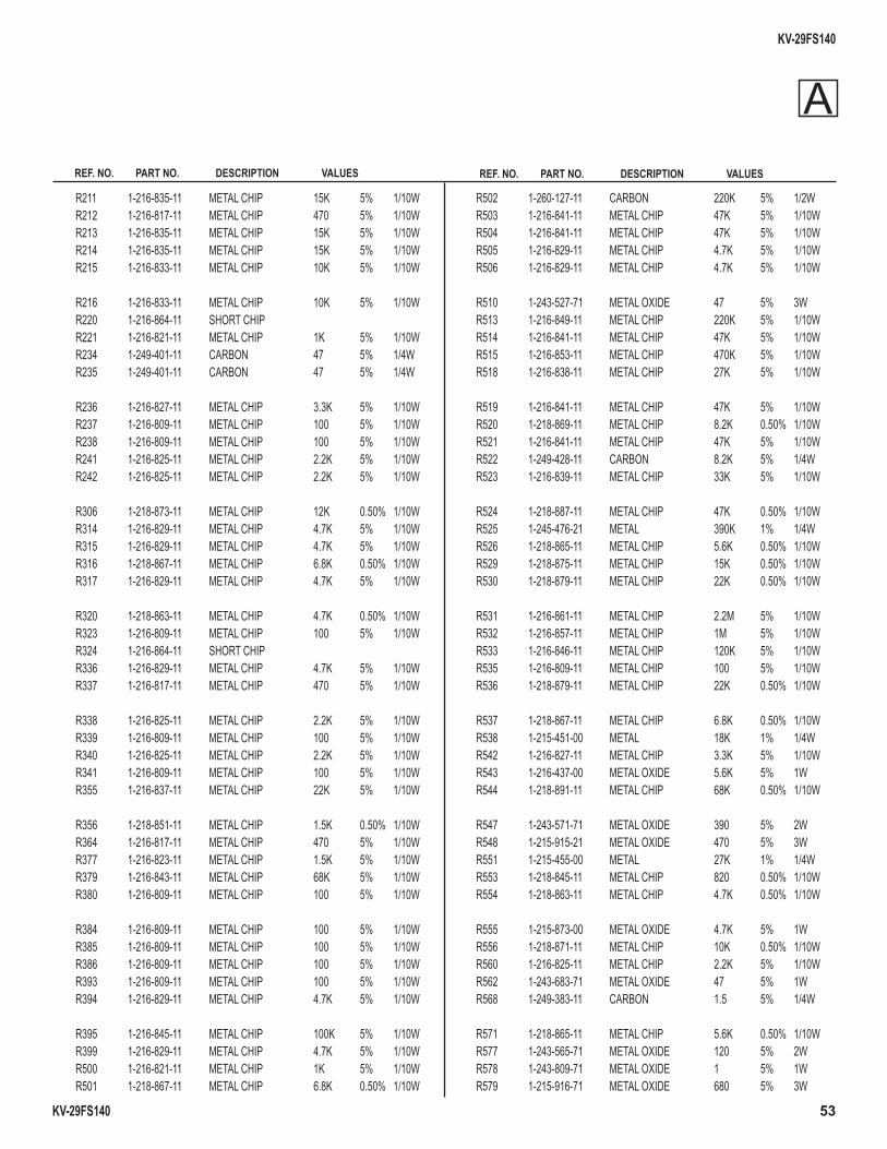
KV-29FS140
KV-29FS140 53
REF. NO. PART NO. DESCRIPTION VALUES REF. NO. PART NO. DESCRIPTION VALUES
R211 1-216-835-11 METAL CHIP 15K 5% 1/10W R212 1-216-817-11 METAL CHIP 470 5% 1/10W R213 1-216-835-11 METAL CHIP 15K 5% 1/10W R214 1-216-835-11 METAL CHIP 15K 5% 1/10W R215 1-216-833-11 METAL CHIP 10K 5% 1/10W
R216 1-216-833-11 METAL CHIP 10K 5% 1/10W R220 1-216-864-11 SHORT CHIP R221 1-216-821-11 METAL CHIP 1K 5% 1/10W R234 1-249-401-11 CARBON 47 5% 1/4W R235 1-249-401-11 CARBON 47 5% 1/4W
R236 1-216-827-11 METAL CHIP 3.3K 5% 1/10W R237 1-216-809-11 METAL CHIP 100 5% 1/10W R238 1-216-809-11 METAL CHIP 100 5% 1/10W R241 1-216-825-11 METAL CHIP 2.2K 5% 1/10W R242 1-216-825-11 METAL CHIP 2.2K 5% 1/10W
R306 1-218-873-11 METAL CHIP 12K 0.50% 1/10W R314 1-216-829-11 METAL CHIP 4.7K 5% 1/10W R315 1-216-829-11 METAL CHIP 4.7K 5% 1/10W R316 1-218-867-11 METAL CHIP 6.8K 0.50% 1/10W R317 1-216-829-11 METAL CHIP 4.7K 5% 1/10W
R320 1-218-863-11 METAL CHIP 4.7K 0.50% 1/10W R323 1-216-809-11 METAL CHIP 100 5% 1/10W R324 1-216-864-11 SHORT CHIP R336 1-216-829-11 METAL CHIP 4.7K 5% 1/10W R337 1-216-817-11 METAL CHIP 470 5% 1/10W
R338 1-216-825-11 METAL CHIP 2.2K 5% 1/10W R339 1-216-809-11 METAL CHIP 100 5% 1/10W R340 1-216-825-11 METAL CHIP 2.2K 5% 1/10W R341 1-216-809-11 METAL CHIP 100 5% 1/10W R355 1-216-837-11 METAL CHIP 22K 5% 1/10W
R356 1-218-851-11 METAL CHIP 1.5K 0.50% 1/10W R364 1-216-817-11 METAL CHIP 470 5% 1/10W R377 1-216-823-11 METAL CHIP 1.5K 5% 1/10W R379 1-216-843-11 METAL CHIP 68K 5% 1/10W R380 1-216-809-11 METAL CHIP 100 5% 1/10W
R384 1-216-809-11 METAL CHIP 100 5% 1/10W R385 1-216-809-11 METAL CHIP 100 5% 1/10W R386 1-216-809-11 METAL CHIP 100 5% 1/10W R393 1-216-809-11 METAL CHIP 100 5% 1/10W R394 1-216-829-11 METAL CHIP 4.7K 5% 1/10W
R395 1-216-845-11 METAL CHIP 100K 5% 1/10W R399 1-216-829-11 METAL CHIP 4.7K 5% 1/10W R500 1-216-821-11 METAL CHIP 1K 5% 1/10W R501 1-218-867-11 METAL CHIP 6.8K 0.50% 1/10W
R502 1-260-127-11 CARBON 220K 5% 1/2W R503 1-216-841-11 METAL CHIP 47K 5% 1/10W R504 1-216-841-11 METAL CHIP 47K 5% 1/10W R505 1-216-829-11 METAL CHIP 4.7K 5% 1/10W R506 1-216-829-11 METAL CHIP 4.7K 5% 1/10W
R510 1-243-527-71 METAL OXIDE 47 5% 3W R513 1-216-849-11 METAL CHIP 220K 5% 1/10W R514 1-216-841-11 METAL CHIP 47K 5% 1/10W R515 1-216-853-11 METAL CHIP 470K 5% 1/10W R518 1-216-838-11 METAL CHIP 27K 5% 1/10W
R519 1-216-841-11 METAL CHIP 47K 5% 1/10W R520 1-218-869-11 METAL CHIP 8.2K 0.50% 1/10W R521 1-216-841-11 METAL CHIP 47K 5% 1/10W R522 1-249-428-11 CARBON 8.2K 5% 1/4W R523 1-216-839-11 METAL CHIP 33K 5% 1/10W
R524 1-218-887-11 METAL CHIP 47K 0.50% 1/10W R525 1-245-476-21 METAL 390K 1% 1/4W R526 1-218-865-11 METAL CHIP 5.6K 0.50% 1/10W R529 1-218-875-11 METAL CHIP 15K 0.50% 1/10W R530 1-218-879-11 METAL CHIP 22K 0.50% 1/10W
R531 1-216-861-11 METAL CHIP 2.2M 5% 1/10W R532 1-216-857-11 METAL CHIP 1M 5% 1/10W R533 1-216-846-11 METAL CHIP 120K 5% 1/10W R535 1-216-809-11 METAL CHIP 100 5% 1/10W R536 1-218-879-11 METAL CHIP 22K 0.50% 1/10W
R537 1-218-867-11 METAL CHIP 6.8K 0.50% 1/10W R538 1-215-451-00 METAL 18K 1% 1/4W R542 1-216-827-11 METAL CHIP 3.3K 5% 1/10W R543 1-216-437-00 METAL OXIDE 5.6K 5% 1W R544 1-218-891-11 METAL CHIP 68K 0.50% 1/10W
R547 1-243-571-71 METAL OXIDE 390 5% 2W R548 1-215-915-21 METAL OXIDE 470 5% 3W R551 1-215-455-00 METAL 27K 1% 1/4W R553 1-218-845-11 METAL CHIP 820 0.50% 1/10W R554 1-218-863-11 METAL CHIP 4.7K 0.50% 1/10W
R555 1-215-873-00 METAL OXIDE 4.7K 5% 1W R556 1-218-871-11 METAL CHIP 10K 0.50% 1/10W R560 1-216-825-11 METAL CHIP 2.2K 5% 1/10W R562 1-243-683-71 METAL OXIDE 47 5% 1W R568 1-249-383-11 CARBON 1.5 5% 1/4W
R571 1-218-865-11 METAL CHIP 5.6K 0.50% 1/10W R577 1-243-565-71 METAL OXIDE 120 5% 2W R578 1-243-809-71 METAL OXIDE 1 5% 1W R579 1-215-916-71 METAL OXIDE 680 5% 3W
A
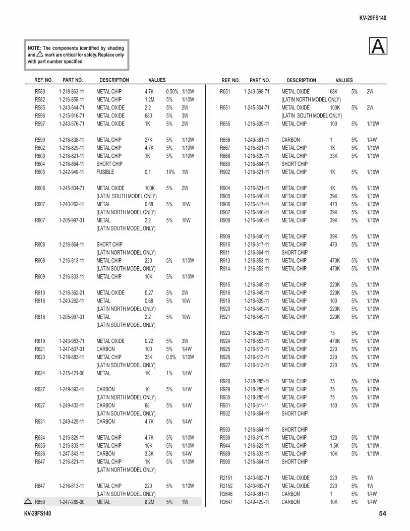
KV-29FS140
KV-29FS140 54
REF. NO. PART NO. DESCRIPTION VALUES REF. NO. PART NO. DESCRIPTION VALUES
NOTE: The components identifi ed by shading and ! mark are critical for safety. Replace only with part number specifi ed.
R580 1-218-863-11 METAL CHIP 4.7K 0.50% 1/10W R582 1-216-858-11 METAL CHIP 1.2M 5% 1/10W R585 1-243-544-71 METAL OXIDE 2.2 5% 2W R596 1-215-916-71 METAL OXIDE 680 5% 3W R597 1-243-576-71 METAL OXIDE 1K 5% 2W
R599 1-216-838-11 METAL CHIP 27K 5% 1/10W R602 1-216-829-11 METAL CHIP 4.7K 5% 1/10W R603 1-216-821-11 METAL CHIP 1K 5% 1/10W R604 1-216-864-11 SHORT CHIP R605 1-242-949-11 FUSIBLE 0.1 10% 1W
R606 1-245-504-71 METAL OXIDE 100K 5% 2W (LATIN SOUTH MODEL ONLY) R607 1-240-262-11 METAL 0.68 5% 10W (LATIN NORTH MODEL ONLY) R607 1-205-997-31 METAL 2.2 5% 10W (LATIN SOUTH MODEL ONLY)
R608 1-216-864-11 SHORT CHIP (LATIN NORTH MODEL ONLY) R608 1-216-813-11 METAL CHIP 220 5% 1/10W (LATIN SOUTH MODEL ONLY) R609 1-216-833-11 METAL CHIP 10K 5% 1/10W
R610 1-216-362-21 METAL OXIDE 0.27 5% 2W R616 1-240-262-11 METAL 0.68 5% 10W (LATIN NORTH MODEL ONLY) R616 1-205-997-31 METAL 2.2 5% 10W (LATIN SOUTH MODEL ONLY)
R619 1-243-953-71 METAL OXIDE 0.22 5% 3W R621 1-247-807-31 CARBON 100 5% 1/4W R623 1-218-883-11 METAL CHIP 33K 0.5% 1/10W (LATIN SOUTH MODEL ONLY) R624 1-215-421-00 METAL 1K 1% 1/4W
R627 1-249-393-11 CARBON 10 5% 1/4W (LATIN NORTH MODEL ONLY) R627 1-249-403-11 CARBON 68 5% 1/4W (LATIN SOUTH MODEL ONLY) R631 1-249-425-11 CARBON 4.7K 5% 1/4W
R634 1-216-829-11 METAL CHIP 4.7K 5% 1/10W R635 1-216-833-11 METAL CHIP 10K 5% 1/10W R636 1-247-843-11 CARBON 3.3K 5% 1/4W R647 1-216-821-11 METAL CHIP 1K 5% 1/10W (LATIN NORTH MODEL ONLY)
R647 1-216-813-11 METAL CHIP 220 5% 1/10W (LATIN SOUTH MODEL ONLY)
! R650 1-247-289-00 METAL 8.2M 5% 1W
R651 1-243-598-71 METAL OXIDE 68K 5% 2W (LATIN NORTH MODEL ONLY) R651 1-245-504-71 METAL OXIDE 100K 5% 2W (LATIN SOUTH MODEL ONLY) R655 1-216-809-11 METAL CHIP 100 5% 1/10W
R656 1-249-381-11 CARBON 1 5% 1/4W R667 1-216-821-11 METAL CHIP 1K 5% 1/10W R668 1-216-839-11 METAL CHIP 33K 5% 1/10W R680 1-216-864-11 SHORT CHIP R902 1-216-821-11 METAL CHIP 1K 5% 1/10W
R904 1-216-821-11 METAL CHIP 1K 5% 1/10W R905 1-216-840-11 METAL CHIP 39K 5% 1/10W R906 1-216-817-11 METAL CHIP 470 5% 1/10W R907 1-216-840-11 METAL CHIP 39K 5% 1/10W R908 1-216-840-11 METAL CHIP 39K 5% 1/10W
R909 1-216-840-11 METAL CHIP 39K 5% 1/10W R910 1-216-817-11 METAL CHIP 470 5% 1/10W R911 1-216-864-11 SHORT CHIP R913 1-216-853-11 METAL CHIP 470K 5% 1/10W R914 1-216-853-11 METAL CHIP 470K 5% 1/10W
R915 1-216-849-11 METAL CHIP 220K 5% 1/10W R916 1-216-849-11 METAL CHIP 220K 5% 1/10W R919 1-216-809-11 METAL CHIP 100 5% 1/10W R920 1-216-849-11 METAL CHIP 220K 5% 1/10W R921 1-216-849-11 METAL CHIP 220K 5% 1/10W
R923 1-218-285-11 METAL CHIP 75 5% 1/10W R924 1-216-853-11 METAL CHIP 470K 5% 1/10W R925 1-216-813-11 METAL CHIP 220 5% 1/10W R926 1-216-813-11 METAL CHIP 220 5% 1/10W R927 1-216-813-11 METAL CHIP 220 5% 1/10W
R928 1-218-285-11 METAL CHIP 75 5% 1/10W R929 1-218-285-11 METAL CHIP 75 5% 1/10W R930 1-218-285-11 METAL CHIP 75 5% 1/10W R931 1-216-811-11 METAL CHIP 150 5% 1/10W R932 1-216-864-11 SHORT CHIP
R933 1-216-864-11 SHORT CHIP R939 1-216-810-11 METAL CHIP 120 5% 1/10W R944 1-216-823-11 METAL CHIP 1.5K 5% 1/10W R989 1-216-833-11 METAL CHIP 10K 5% 1/10W R990 1-216-864-11 SHORT CHIP
R2151 1-243-692-71 METAL OXIDE 220 5% 1W R2152 1-243-692-71 METAL OXIDE 220 5% 1W R2646 1-249-381-11 CARBON 1 5% 1/4W R2647 1-249-429-11 CARBON 10K 5% 1/4W
A
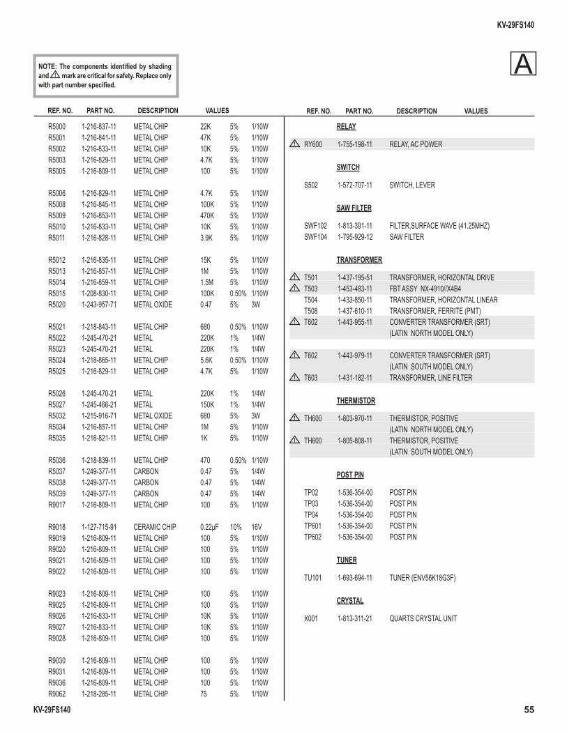
KV-29FS140
KV-29FS140 55
REF. NO. PART NO. DESCRIPTION VALUES REF. NO. PART NO. DESCRIPTION VALUES
NOTE: The components identifi ed by shading and ! mark are critical for safety. Replace only with part number specifi ed.
R5000 1-216-837-11 METAL CHIP 22K 5% 1/10W R5001 1-216-841-11 METAL CHIP 47K 5% 1/10W R5002 1-216-833-11 METAL CHIP 10K 5% 1/10W R5003 1-216-829-11 METAL CHIP 4.7K 5% 1/10W R5005 1-216-809-11 METAL CHIP 100 5% 1/10W
R5006 1-216-829-11 METAL CHIP 4.7K 5% 1/10W R5008 1-216-845-11 METAL CHIP 100K 5% 1/10W R5009 1-216-853-11 METAL CHIP 470K 5% 1/10W R5010 1-216-833-11 METAL CHIP 10K 5% 1/10W R5011 1-216-828-11 METAL CHIP 3.9K 5% 1/10W
R5012 1-216-835-11 METAL CHIP 15K 5% 1/10W R5013 1-216-857-11 METAL CHIP 1M 5% 1/10W R5014 1-216-859-11 METAL CHIP 1.5M 5% 1/10W R5015 1-208-830-11 METAL CHIP 100K 0.50% 1/10W R5020 1-243-957-71 METAL OXIDE 0.47 5% 3W
R5021 1-218-843-11 METAL CHIP 680 0.50% 1/10W R5022 1-245-470-21 METAL 220K 1% 1/4W R5023 1-245-470-21 METAL 220K 1% 1/4W R5024 1-218-865-11 METAL CHIP 5.6K 0.50% 1/10W R5025 1-216-829-11 METAL CHIP 4.7K 5% 1/10W
R5026 1-245-470-21 METAL 220K 1% 1/4W R5027 1-245-466-21 METAL 150K 1% 1/4W R5032 1-215-916-71 METAL OXIDE 680 5% 3W R5034 1-216-857-11 METAL CHIP 1M 5% 1/10W R5035 1-216-821-11 METAL CHIP 1K 5% 1/10W
R5036 1-218-839-11 METAL CHIP 470 0.50% 1/10W R5037 1-249-377-11 CARBON 0.47 5% 1/4W R5038 1-249-377-11 CARBON 0.47 5% 1/4W R5039 1-249-377-11 CARBON 0.47 5% 1/4W R9017 1-216-809-11 METAL CHIP 100 5% 1/10W
R9018 1-127-715-91 CERAMIC CHIP 0.22µF 10% 16V R9019 1-216-809-11 METAL CHIP 100 5% 1/10W R9020 1-216-809-11 METAL CHIP 100 5% 1/10W R9021 1-216-809-11 METAL CHIP 100 5% 1/10W R9022 1-216-809-11 METAL CHIP 100 5% 1/10W
R9023 1-216-809-11 METAL CHIP 100 5% 1/10W R9025 1-216-809-11 METAL CHIP 100 5% 1/10W R9026 1-216-833-11 METAL CHIP 10K 5% 1/10W R9027 1-216-833-11 METAL CHIP 10K 5% 1/10W R9028 1-216-809-11 METAL CHIP 100 5% 1/10W
R9030 1-216-809-11 METAL CHIP 100 5% 1/10W R9031 1-216-809-11 METAL CHIP 100 5% 1/10W R9036 1-216-809-11 METAL CHIP 100 5% 1/10W R9062 1-218-285-11 METAL CHIP 75 5% 1/10W
RELAY
! RY600 1-755-198-11 RELAY, AC POWER
SWITCH
S502 1-572-707-11 SWITCH, LEVER
SAW FILTER
SWF102 1-813-391-11 FILTER,SURFACE WAVE (41.25MHZ) SWF104 1-795-929-12 SAW FILTER
TRANSFORMER
! T501 1-437-195-51 TRANSFORMER, HORIZONTAL DRIVE ! T503 1-453-483-11 FBT ASSY NX-4910//X4B4
T504 1-433-850-11 TRANSFORMER, HORIZONTAL LINEAR T508 1-437-610-11 TRANSFORMER, FERRITE (PMT)
! T602 1-443-955-11 CONVERTER TRANSFORMER (SRT) (LATIN NORTH MODEL ONLY)
! T602 1-443-979-11 CONVERTER TRANSFORMER (SRT) (LATIN SOUTH MODEL ONLY)
! T603 1-431-182-11 TRANSFORMER, LINE FILTER
THERMISTOR
! TH600 1-803-970-11 THERMISTOR, POSITIVE (LATIN NORTH MODEL ONLY)
! TH600 1-805-808-11 THERMISTOR, POSITIVE (LATIN SOUTH MODEL ONLY)
POST PIN
TP02 1-536-354-00 POST PIN TP03 1-536-354-00 POST PIN TP04 1-536-354-00 POST PIN TP601 1-536-354-00 POST PIN TP602 1-536-354-00 POST PIN
TUNER
TU101 1-693-694-11 TUNER (ENV56K18G3F)
CRYSTAL
X001 1-813-311-21 QUARTS CRYSTAL UNIT
A
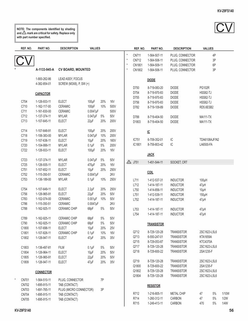
KV-29FS140
KV-29FS140 56
REF. NO. PART NO. DESCRIPTION VALUES REF. NO. PART NO. DESCRIPTION VALUES
NOTE: The components identifi ed by shading and ! mark are critical for safety. Replace only with part number specifi ed.
CV* A-1133-945-A CV BOARD, MOUNTED
1-900-262-86 LEAD ASSY, FOCUS 4-382-854-01 SCREW (M3X8), P, SW (+)
CAPACITOR
C704 1-126-933-11 ELECT 100µF 20% 16V C710 1-162-117-00 CERAMIC 100pF 10% 500V C711 1-161-830-00 CERAMIC 0.0047µF 500V C712 1-137-374-11 MYLAR 0.047µF 5% 50V C713 1-107-645-11 ELECT 22µF 20% 200V C714 1-107-648-91 ELECT 100µF 20% 200V C718 1-106-383-00 MYLAR 0.047µF 10% 200V C719 1-107-636-11 ELECT 10µF 20% 160V C720 1-104-999-11 MYLAR 0.1µF 5% 200V C722 1-126-933-11 ELECT 100µF 20% 16V C723 1-137-374-11 MYLAR 0.047µF 5% 50V C725 1-126-935-11 ELECT 470µF 20% 16V C751 1-107-652-11 ELECT 10µF 20% 250V C752 1-115-350-51 CERAMIC 0.0047µF 2KV C753 1-136-189-00 MYLAR 0.1µF 10% 250V C754 1-107-649-11 ELECT 2.2µF 20% 250V C756 1-126-965-91 ELECT 22µF 20% 50V C783 1-102-074-00 CERAMIC 0.001µF 10% 50V C786 1-115-350-51 CERAMIC 0.0047µF 2KV C788 1-162-925-11 CERAMIC CHIP 68pF 5% 50V C789 1-162-925-11 CERAMIC CHIP 68pF 5% 50V C790 1-162-925-11 CERAMIC CHIP 68pF 5% 50V C1800 1-107-698-11 ELECT 10µF 20% 25V C1801 1-107-826-11 CERAMIC CHIP 0.1µF 10% 16V C1802 1-126-947-11 ELECT 47µF 20% 35V C1803 1-136-497-81 FILM 0.1µF 5% 50V C1804 1-126-964-11 ELECT 10µF 20% 50V C1805 1-126-965-91 ELECT 22µF 20% 50V C1809 1-126-947-11 ELECT 47µF 20% 35V
CONNECTOR
* CN701 1-564-510-11 PLUG, CONNECTOR 7P CN702 1-695-915-11 TAB (CONTACT) CN703 1-691-765-11 PLUG (MICRO CONNECTOR) 3P CN704 1-695-915-11 TAB (CONTACT) CN705 1-695-915-11 TAB (CONTACT)
* CN711 1-564-507-11 PLUG, CONNECTOR 4P * CN712 1-564-506-11 PLUG, CONNECTOR 3P * CN1801 1-564-509-11 PLUG, CONNECTOR 6P * CN1802 1-564-506-11 PLUG, CONNECTOR 3P
DIODE
D750 8-719-083-20 DIODE PG102R D754 8-719-970-83 DIODE HSS82-TJ D755 8-719-970-83 DIODE HSS82-TJ D756 8-719-970-83 DIODE HSS82-TJ D782 8-719-109-89 DIODE RD5.6ESB2
D788 8-719-404-50 DIODE MA111-TX D1803 8-719-404-50 DIODE MA111-TX
IC
IC751 6-709-352-01 IC TDA6108AJF/N2 IC1801 8-759-803-42 IC LA6500-FA
JACK
! J751 1-451-544-11 SOCKET, CRT
COIL
L711 1-412-537-31 INDUCTOR 100µH L712 1-414-187-11 INDUCTOR 47µH L750 1-414-856-11 INDUCTOR 10µH L751 1-412-539-11 INDUCTOR 150µH L752 1-414-187-11 INDUCTOR 47µH
L753 1-414-187-11 INDUCTOR 47µH L754 1-414-187-11 INDUCTOR 47µH
TRANSISTOR
Q712 8-729-120-28 TRANSISTOR 2SC1623-L5L6 Q713 6-550-247-01 TRANSISTOR KTA1659A Q715 8-729-053-87 TRANSISTOR KTC4370A Q717 8-729-120-28 TRANSISTOR 2SC1623-L5L6 Q718 8-729-600-22 TRANSISTOR 2SA1235-F
Q719 8-729-120-28 TRANSISTOR 2SC1623-L5L6 Q1800 8-729-600-22 TRANSISTOR 2SA1235-F Q1802 8-729-120-28 TRANSISTOR 2SC1623-L5L6 Q1804 8-729-120-28 TRANSISTOR 2SC1623-L5L6
RESISTOR
R712 1-216-805-11 METAL CHIP 47 5% 1/10W R714 1-260-312-11 CARBON 47 5% 1/2W R715 1-249-413-11 CARBON 470 5% 1/4W
CV
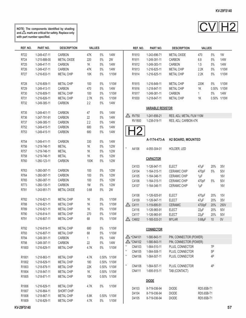
KV-29FS140
KV-29FS140 57
REF. NO. PART NO. DESCRIPTION VALUES REF. NO. PART NO. DESCRIPTION VALUES
NOTE: The components identifi ed by shading and ! mark are critical for safety. Replace only with part number specifi ed.
R722 1-249-437-11 CARBON 47K 5% 1/4W R724 1-215-888-00 METAL OXIDE 220 5% 2W R725 1-249-417-11 CARBON 1K 5% 1/4W R726 1-249-437-11 CARBON 47K 5% 1/4W R727 1-216-833-11 METAL CHIP 10K 5% 1/10W
R728 1-216-809-11 METAL CHIP 100 5% 1/10W R729 1-249-413-11 CARBON 470 5% 1/4W R730 1-216-809-11 METAL CHIP 100 5% 1/10W R731 1-216-826-11 METAL CHIP 2.7K 5% 1/10W R732 1-249-385-11 CARBON 2.2 5% 1/4W
R735 1-249-401-11 CARBON 47 5% 1/4W R736 1-247-791-91 CARBON 22 5% 1/4W R737 1-249-385-11 CARBON 2.2 5% 1/4W R752 1-249-415-11 CARBON 680 5% 1/4W R753 1-249-415-11 CARBON 680 5% 1/4W
R754 1-249-411-11 CARBON 330 5% 1/4W R756 1-219-746-11 METAL 1K 5% 1/2W R757 1-219-746-11 METAL 1K 5% 1/2W R758 1-219-746-11 METAL 1K 5% 1/2W R760 1-260-123-11 CARBON 100K 5% 1/2W
R763 1-260-087-11 CARBON 100 5% 1/2W R764 1-260-087-11 CARBON 100 5% 1/2W R765 1-260-087-11 CARBON 100 5% 1/2W R773 1-260-135-11 CARBON 1M 5% 1/2W R781 1-243-951-71 METAL OXIDE 0.68 5% 2W
R782 1-216-821-11 METAL CHIP 1K 5% 1/10W R788 1-216-821-11 METAL CHIP 1K 5% 1/10W R789 1-216-821-11 METAL CHIP 1K 5% 1/10W R790 1-216-814-11 METAL CHIP 270 5% 1/10W R791 1-216-807-11 METAL CHIP 68 5% 1/10W
R792 1-216-819-11 METAL CHIP 680 5% 1/10W R793 1-216-807-11 METAL CHIP 68 5% 1/10W R794 1-249-381-11 CARBON 1 5% 1/4W R798 1-249-397-11 CARBON 22 5% 1/4W R1800 1-216-829-11 METAL CHIP 4.7K 5% 1/10W
R1801 1-218-863-11 METAL CHIP 4.7K 0.50% 1/10W R1802 1-218-829-11 METAL CHIP 180 0.50% 1/10W R1803 1-218-879-11 METAL CHIP 22K 0.50% 1/10W R1804 1-218-847-11 METAL CHIP 1K 0.50% 1/10W R1805 1-218-871-11 METAL CHIP 10K 0.50% 1/10W
R1806 1-216-829-11 METAL CHIP 4.7K 5% 1/10W R1807 1-216-864-11 SHORT CHIP R1808 1-218-867-11 METAL CHIP 6.8K 0.50% 1/10W R1809 1-216-829-11 METAL CHIP 4.7K 5% 1/10W
R1810 1-243-696-71 METAL OXIDE 470 5% 1W R1811 1-249-391-11 CARBON 6.8 5% 1/4W R1812 1-249-383-11 CARBON 1.5 5% 1/4W R1813 1-216-825-11 METAL CHIP 2.2K 5% 1/10W R1814 1-216-825-11 METAL CHIP 2.2K 5% 1/10W
R1815 1-216-849-11 METAL CHIP 220K 5% 1/10W R1816 1-218-847-11 METAL CHIP 1K 0.50% 1/10W R1817 1-249-381-11 CARBON 1 5% 1/4W R1830 1-218-847-11 METAL CHIP 1K 0.50% 1/10W
VARIABLE RESISTOR
! RV750 1-241-656-21 RES, ADJ, METAL FILM 110M RV1800 1-238-019-11 RES, ADJ, CARBON 47K
H2 A-1174-473-A H2 BOARD, MOUNTED
* A4106 4-055-304-01 HOLDER, LED
CAPACITOR
C4103 1-126-947-11 ELECT 47µF 20% 35V C4104 1-164-315-11 CERAMIC CHIP 470pF 5% 50V C4105 1-164-346-11 CERAMIC CHIP 1µF 16V C4106 1-164-315-11 CERAMIC CHIP 470pF 5% 50V C4107 1-164-346-11 CERAMIC CHIP 1µF 16V
C4108 1-126-925-91 ELECT 470µF 20% 10V C4109 1-126-947-11 ELECT 47µF 20% 35V
! C4111 1-119-895-51 CERAMIC 4700pF 20% 250V C4116 1-126-965-91 ELECT 22µF 20% 50V C4117 1-126-965-91 ELECT 22µF 20% 50V
! C4602 1-165-533-31 MYLAR 0.68µF 10 0V
CONNECTOR
! * CN4101 1-580-843-11 PIN, CONNECTOR (POWER) ! * CN4102 1-580-843-11 PIN, CONNECTOR (POWER)
* CN4103 1-564-510-11 PLUG, CONNECTOR 7P * CN4105 1-564-508-11 PLUG, CONNECTOR 5P * CN4106 1-564-507-11 PLUG, CONNECTOR 4P
* CN4108 1-564-507-11 PLUG, CONNECTOR 4P CN4111 1-695-915-11 TAB (CONTACT)
DIODE
D4103 8-719-036-94 DIODE RD5.6SB-T1 D4104 8-719-036-94 DIODE RD5.6SB-T1 D4105 8-719-036-94 DIODE RD5.6SB-T1
CV H2
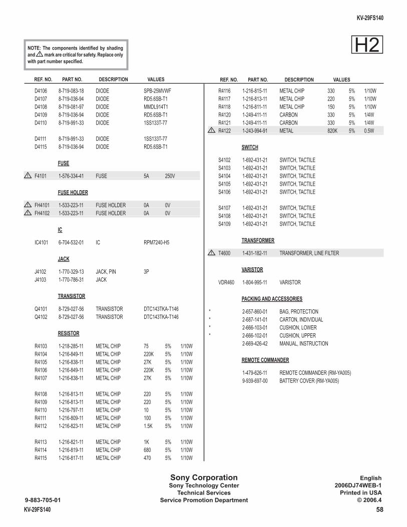
KV-29FS140
KV-29FS140 58
Sony CorporationSony Technology Center
Technical ServicesService Promotion Department9-883-705-01
English2006DJ74WEB-1
Printed in USA© 2006.4
REF. NO. PART NO. DESCRIPTION VALUES REF. NO. PART NO. DESCRIPTION VALUES
D4106 8-719-083-18 DIODE SPB-25MVWF D4107 8-719-036-94 DIODE RD5.6SB-T1 D4108 8-719-081-97 DIODE MMDL914T1 D4109 8-719-036-94 DIODE RD5.6SB-T1 D4110 8-719-991-33 DIODE 1SS133T-77
D4111 8-719-991-33 DIODE 1SS133T-77 D4115 8-719-036-94 DIODE RD5.6SB-T1
FUSE
! F4101 1-576-334-41 FUSE 5A 250V
FUSE HOLDER
! FH4101 1-533-223-11 FUSE HOLDER 0A 0V! FH4102 1-533-223-11 FUSE HOLDER 0A 0V
IC
IC4101 6-704-532-01 IC RPM7240-H5
JACK
J4102 1-770-329-13 JACK, PIN 3P J4103 1-770-786-31 JACK
TRANSISTOR
Q4101 8-729-027-56 TRANSISTOR DTC143TKA-T146 Q4102 8-729-027-56 TRANSISTOR DTC143TKA-T146
RESISTOR
R4103 1-218-285-11 METAL CHIP 75 5% 1/10W R4104 1-216-849-11 METAL CHIP 220K 5% 1/10W R4105 1-216-838-11 METAL CHIP 27K 5% 1/10W R4106 1-216-849-11 METAL CHIP 220K 5% 1/10W R4107 1-216-838-11 METAL CHIP 27K 5% 1/10W R4108 1-216-813-11 METAL CHIP 220 5% 1/10W R4109 1-216-813-11 METAL CHIP 220 5% 1/10W R4110 1-216-797-11 METAL CHIP 10 5% 1/10W R4111 1-216-809-11 METAL CHIP 100 5% 1/10W R4112 1-216-823-11 METAL CHIP 1.5K 5% 1/10W R4113 1-216-821-11 METAL CHIP 1K 5% 1/10W R4114 1-216-819-11 METAL CHIP 680 5% 1/10W R4115 1-216-817-11 METAL CHIP 470 5% 1/10W
R4116 1-216-815-11 METAL CHIP 330 5% 1/10W R4117 1-216-813-11 METAL CHIP 220 5% 1/10W R4118 1-216-811-11 METAL CHIP 150 5% 1/10W R4120 1-249-411-11 CARBON 330 5% 1/4W R4121 1-249-411-11 CARBON 330 5% 1/4W
! R4122 1-243-994-91 METAL 820K 5% 0.5W
SWITCH
S4102 1-692-431-21 SWITCH, TACTILE S4103 1-692-431-21 SWITCH, TACTILE S4104 1-692-431-21 SWITCH, TACTILE S4105 1-692-431-21 SWITCH, TACTILE S4106 1-692-431-21 SWITCH, TACTILE
S4107 1-692-431-21 SWITCH, TACTILE S4108 1-692-431-21 SWITCH, TACTILE S4109 1-692-431-21 SWITCH, TACTILE
TRANSFORMER
! T4600 1-431-182-11 TRANSFORMER, LINE FILTER
VARISTOR
VDR460 1-804-995-11 VARISTOR
PACKING AND ACCESSORIES
* 2-657-860-01 BAG, PROTECTION * 2-687-141-01 CARTON, INDIVIDUAL * 2-666-103-01 CUSHION, LOWER * 2-666-102-01 CUSHION, UPPER 2-669-426-42 MANUAL, INSTRUCTION
REMOTE COMMANDER
1-479-626-11 REMOTE COMMANDER (RM-YA005) 9-939-697-00 BATTERY COVER (RM-YA005)
H2NOTE: The components identifi ed by shading and ! mark are critical for safety. Replace only with part number specifi ed.
SERVICE MANUAL BX-1L CHASSIS
In an effort to reduce the size of this pdf fi le the tiled schematics are not attached to this Service Manual. To receive a complete set of the tiled schematics for this manual please submit a request to: [email protected].
Related Documents