Solid Drilling Tools Type 1475 / 1476 DEEP HOLE DRILLING TOOLS BORING RANGE Ø65,00 - 161,99 mm SOLID DRILLING TOOLS | 2017

Welcome message from author
This document is posted to help you gain knowledge. Please leave a comment to let me know what you think about it! Share it to your friends and learn new things together.
Transcript
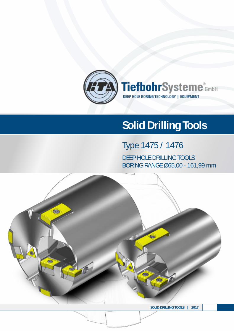
Solid Drilling Tools
Type 1475 / 1476
DEEP HOLE DRILLING TOOLSBORING RANGE Ø65,00 - 161,99 mm
SOLID DRILLING TOOLS | 2017
Contents
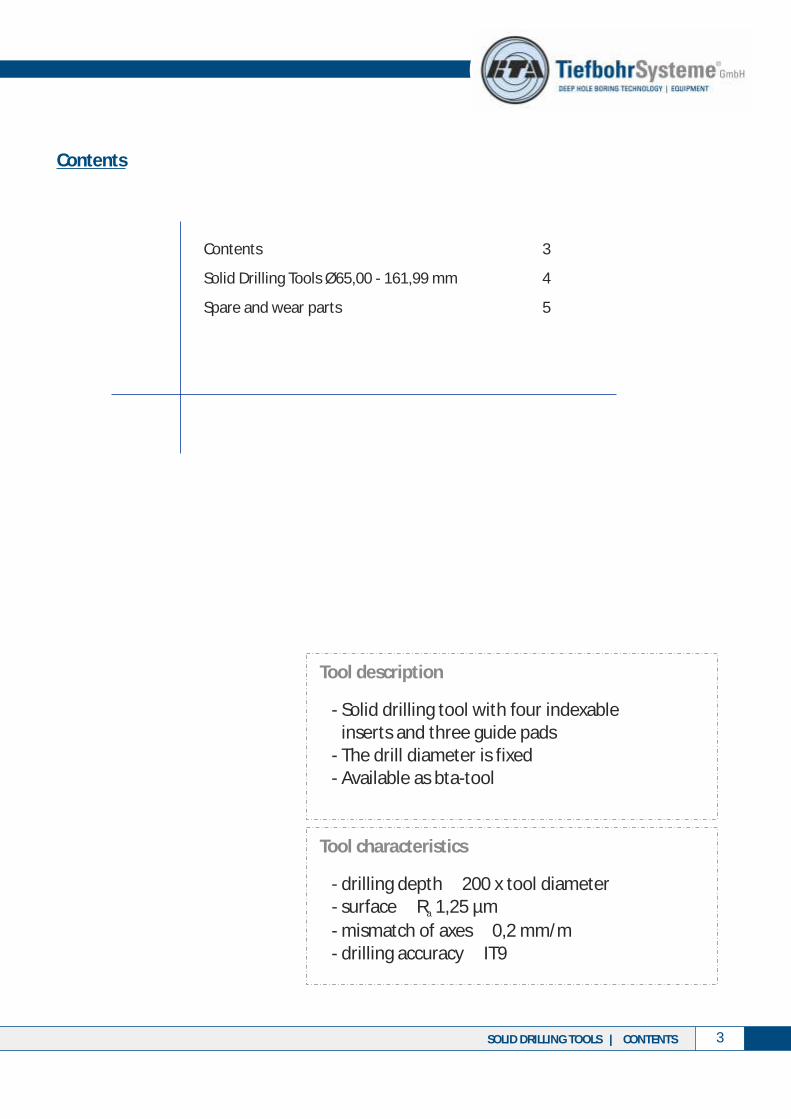
Contents 3
Solid Drilling Tools Ø65,00 - 161,99 mm 4
Spare and wear parts 5
32 SOLID DRILLING TOOLS | CONTENTSSOLID DRILLING TOOLS | GENERAL INFORMATION
- drilling depth 200 x tool diameter- surface ≥ R 1,25 µm
- mismatch of axes ≥ 0,2 mm/m- drilling accuracy ≥ IT9
≤
a
Tool characteristics
- Solid drilling tool with four indexable inserts and three guide pads
- The drill diameter is fixed- Available as bta-tool
Tool description
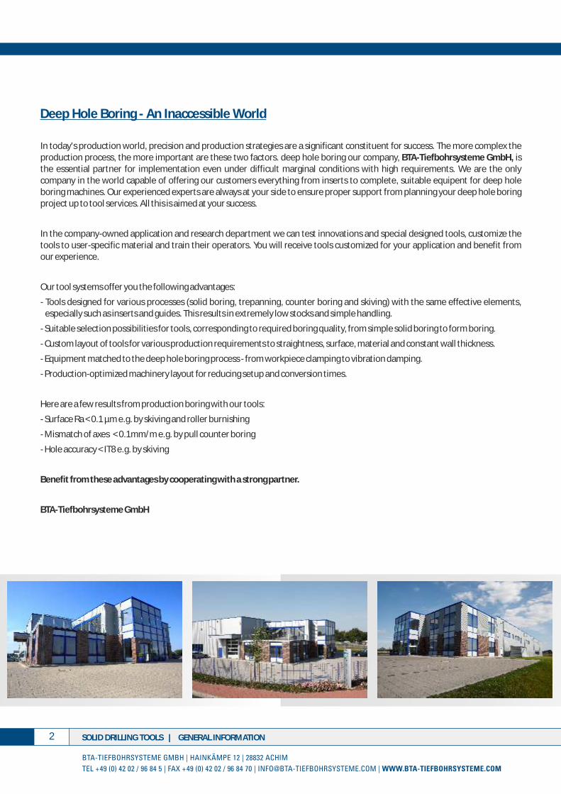
Deep Hole Boring - An Inaccessible World
In today's production world, precision and production strategies are a significant constituent for success. The more complex the production process, the more important are these two factors. deep hole boring our company, BTA-Tiefbohrsysteme GmbH, is the essential partner for implementation even under difficult marginal conditions with high requirements. We are the only company in the world capable of offering our customers everything from inserts to complete, suitable equipent for deep hole boring machines. Our experienced experts are always at your side to ensure proper support from planning your deep hole boring project up to tool services. All this is aimed at your success.
In the company-owned application and research department we can test innovations and special designed tools, customize the tools to user-specific material and train their operators. You will receive tools customized for your application and benefit from our experience.
Our tool systems offer you the following advantages:
- Tools designed for various processes (solid boring, trepanning, counter boring and skiving) with the same effective elements, especially such as inserts and guides. This results in extremely low stocks and simple handling.
- Suitable selection possibilities for tools, corresponding to required boring quality, from simple solid boring to form boring.
- Custom layout of tools for various production requirements to straightness, surface, material and constant wall thickness.
- Equipment matched to the deep hole boring process - from workpiece clamping to vibration damping.
- Production-optimized machinery layout for reducing setup and conversion times.
Here are a few results from production boring with our tools:
- Surface Ra < 0.1 µm e.g. by skiving and roller burnishing
- Mismatch of axes < 0.1mm/m e.g. by pull counter boring
- Hole accuracy < IT8 e.g. by skiving
Benefit from these advantages by cooperating with a strong partner.
BTA-Tiefbohrsysteme GmbH
Contents
Contents 3
Solid Drilling Tools Ø65,00 - 161,99 mm 4
Spare and wear parts 5
32 SOLID DRILLING TOOLS | CONTENTSSOLID DRILLING TOOLS | GENERAL INFORMATION
- drilling depth 200 x tool diameter- surface ≥ R 1,25 µm
- mismatch of axes ≥ 0,2 mm/m- drilling accuracy ≥ IT9
≤
a
Tool characteristics
- Solid drilling tool with four indexable inserts and three guide pads
- The drill diameter is fixed- Available as bta-tool
Tool description
Deep Hole Boring - An Inaccessible World
In today's production world, precision and production strategies are a significant constituent for success. The more complex the production process, the more important are these two factors. deep hole boring our company, BTA-Tiefbohrsysteme GmbH, is the essential partner for implementation even under difficult marginal conditions with high requirements. We are the only company in the world capable of offering our customers everything from inserts to complete, suitable equipent for deep hole boring machines. Our experienced experts are always at your side to ensure proper support from planning your deep hole boring project up to tool services. All this is aimed at your success.
In the company-owned application and research department we can test innovations and special designed tools, customize the tools to user-specific material and train their operators. You will receive tools customized for your application and benefit from our experience.
Our tool systems offer you the following advantages:
- Tools designed for various processes (solid boring, trepanning, counter boring and skiving) with the same effective elements, especially such as inserts and guides. This results in extremely low stocks and simple handling.
- Suitable selection possibilities for tools, corresponding to required boring quality, from simple solid boring to form boring.
- Custom layout of tools for various production requirements to straightness, surface, material and constant wall thickness.
- Equipment matched to the deep hole boring process - from workpiece clamping to vibration damping.
- Production-optimized machinery layout for reducing setup and conversion times.
Here are a few results from production boring with our tools:
- Surface Ra < 0.1 µm e.g. by skiving and roller burnishing
- Mismatch of axes < 0.1mm/m e.g. by pull counter boring
- Hole accuracy < IT8 e.g. by skiving
Benefit from these advantages by cooperating with a strong partner.
BTA-Tiefbohrsysteme GmbH

54 SOLID DRILLING TOOLS | BORING RANGE Ø 65,00 - 161,99 mmSOLID DRILLING TOOLS | BORING RANGE Ø 65,00 - 161,99 mm
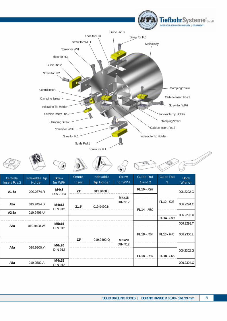
Solid Drilling Tools Type 1475 / 1476
Boring range Ø 65,00 - 161,99 mm
BTA-ThreadType 1475
STS-ThreadType 1476
Possible drill tube connection:
Carbide Insert Pos.1
Guide Pad 2
Guide Pad 1
Screw for FL1
Clamping Screw
Screw for FL2
Main Body
Guide Pad 3
Screw for FL3
Indexable Tip Holder
Screw for WPHIndexable Tip Holder
Carbide Insert Pos.2
Clamping Screw
Clamping Screw
Centre Insert
Shoe for FL1
Shoe for FL2
Shoe for FL3
Indexable Tip Holder
Carbide Insert Pos.3
Clamping Screw
Additional diameters on request
Screw for WPH
Screw for WPH
Screw for WPH
See Page 6/7 for spare and wear parts ordering data
Ce ntre - Inde xa bl e Scre w Gui de Pa d
Ins e rt Ti p Hol de r for WPH 1 a nd 2
Ø 65,00 - Ø 67,99 56 A1,5x 020.1434.EM3x12
DIN 912 Z1³ 019.9488.LFL 10 - R28
Ø 68,00 - Ø 74,99 62 A1,5x 020.0874.R
Ø 75,00 - Ø 80,99 68
Ø 81,00 - Ø 90,99 75 A2,5a 020.0557.B A2a 019.9494.S Z1,5³ 019.9490.N
Ø 91,00 - Ø 98,99 82 A2,5a 019.9496.U A2,5a 019.9496.U
Ø 99,00 - Ø 110,99 94
Ø 111,00 - Ø 117,99
Ø 118,00 - Ø 122,99
Ø 123,00 - Ø 125,99 FL 18 - R40
Ø 126,00 - Ø 134,99 Z2³ 019.9492.Q
Ø 135,00 - Ø 143,99
Ø 144,00 - Ø 148,99
Ø 149,00 - Ø 153,99 A5a 019.9502.A FL 18 - R65
Ø 154,00 - Ø 161,99 A5a 019.9502.AM4x25
DIN 912
Bori ng Ra nge Dri l l Tube
Conne cti on
142
A3a 019.1749.Z
A4a 019.2270.S
Ca rbi de
Ins e rt Pos .1
Inde xa bl e Ti p
Hol de r
106
118
019.2212.GA2a
020.0874.R
019.9494.S
FL 14 - R30
Scre w
for WPH
Ca rbi de
Ins e rt Pos . 2
Inde xa bl e Ti p
Hol de r
Scre w
for WPH
Ca rbi de
Ins e rt Pos .3
Inde xa bl e Ti p
Hol de r
Scre w
for WPH
M5x20
DIN 912
M4x16
DIN 912
019.9500.Y
M6x20
DIN 912
M4x25
DIN 912
M6x20
DIN 912
A1,5x
A2a
M4x16
DIN 6912
M6x30
DIN 6912
A4a
A5a 019.2251.X
130
M4x8
DIN 7984
M4x12
DIN 912
M4x12
DIN 912
M4x8
DIN 7984
M6x25
DIN 6912
M5x16
DIN 912A3a 019.9498.W
M4x20
DIN 6912M5x16
DIN 912A3a 019.9498.W
019.9500.YA4a
Guide Pad
3
FL 10 - R28
FL 14 - R30
006.2298.T
FL 18 - R40 006.2300.L
006.2302.G
FL 18 - R65
006.2304.C
006.2292.G
006.2294.C
006.2296.X
Hook
Wrench
Note: Please activate the two-sided view so that the table is displayed completely.
54 SOLID DRILLING TOOLS | BORING RANGE Ø 65,00 - 161,99 mmSOLID DRILLING TOOLS | BORING RANGE Ø 65,00 - 161,99 mm
Solid Drilling Tools Type 1475 / 1476
Boring range Ø 65,00 - 161,99 mm
BTA-ThreadType 1475
STS-ThreadType 1476
Possible drill tube connection:
Carbide Insert Pos.1
Guide Pad 2
Guide Pad 1
Screw for FL1
Clamping Screw
Screw for FL2
Main Body
Guide Pad 3
Screw for FL3
Indexable Tip Holder
Screw for WPHIndexable Tip Holder
Carbide Insert Pos.2
Clamping Screw
Clamping Screw
Centre Insert
Shoe for FL1
Shoe for FL2
Shoe for FL3
Indexable Tip Holder
Carbide Insert Pos.3
Clamping Screw
Additional diameters on request
Screw for WPH
Screw for WPH
Screw for WPH
See Page 6/7 for spare and wear parts ordering data
Ce ntre - Inde xa bl e Scre w Gui de Pa d
Ins e rt Ti p Hol de r for WPH 1 a nd 2
Ø 65,00 - Ø 67,99 56 A1,5x 020.1434.EM3x12
DIN 912 Z1³ 019.9488.LFL 10 - R28
Ø 68,00 - Ø 74,99 62 A1,5x 020.0874.R
Ø 75,00 - Ø 80,99 68
Ø 81,00 - Ø 90,99 75 A2,5a 020.0557.B A2a 019.9494.S Z1,5³ 019.9490.N
Ø 91,00 - Ø 98,99 82 A2,5a 019.9496.U A2,5a 019.9496.U
Ø 99,00 - Ø 110,99 94
Ø 111,00 - Ø 117,99
Ø 118,00 - Ø 122,99
Ø 123,00 - Ø 125,99 FL 18 - R40
Ø 126,00 - Ø 134,99 Z2³ 019.9492.Q
Ø 135,00 - Ø 143,99
Ø 144,00 - Ø 148,99
Ø 149,00 - Ø 153,99 A5a 019.9502.A FL 18 - R65
Ø 154,00 - Ø 161,99 A5a 019.9502.AM4x25
DIN 912
Bori ng Ra nge Dri l l Tube
Conne cti on
142
A3a 019.1749.Z
A4a 019.2270.S
Ca rbi de
Ins e rt Pos .1
Inde xa bl e Ti p
Hol de r
106
118
019.2212.GA2a
020.0874.R
019.9494.S
FL 14 - R30
Scre w
for WPH
Ca rbi de
Ins e rt Pos . 2
Inde xa bl e Ti p
Hol de r
Scre w
for WPH
Ca rbi de
Ins e rt Pos .3
Inde xa bl e Ti p
Hol de r
Scre w
for WPH
M5x20
DIN 912
M4x16
DIN 912
019.9500.Y
M6x20
DIN 912
M4x25
DIN 912
M6x20
DIN 912
A1,5x
A2a
M4x16
DIN 6912
M6x30
DIN 6912
A4a
A5a 019.2251.X
130
M4x8
DIN 7984
M4x12
DIN 912
M4x12
DIN 912
M4x8
DIN 7984
M6x25
DIN 6912
M5x16
DIN 912A3a 019.9498.W
M4x20
DIN 6912M5x16
DIN 912A3a 019.9498.W
019.9500.YA4a
Guide Pad
3
FL 10 - R28
FL 14 - R30
006.2298.T
FL 18 - R40 006.2300.L
006.2302.G
FL 18 - R65
006.2304.C
006.2292.G
006.2294.C
006.2296.X
Hook
Wrench
Note: Please activate the two-sided view so that the table is displayed completely.

76 SOLID DRILLING TOOLS | SPARE AND WEAR PARTSSOLID DRILLING TOOLS | SPARE AND WEAR PARTS
Guide Pads 1 to 3
Spare and wear parts
For Solid Drilling Tools Type 1475 / 1476
Indexable Inserts Size A1,5a - A5a; Z1³ - Z2³ Screws and Wrenches
M3 / DIN 912 12 008.5836.M
M4 / DIN 7984 8 008.7044.M
12 008.5110.M
25 T.-Nr. 4396
16 008.5002.Q
20 008.5003.N
16 008.5116.Z
20 008.5117.W
M6 / DIN 912 20 008.5122.E 008.5838.H
25 008.5023.G SW 5
30 008.5024.E
SizeIdent-No.
Cla mping Screw
SW
Si ze
Ident-No.
Hexa gon-WrenchLength
M6 / DIN 6912
008.7213.Q
008.6948.U
M4 / DIN 6912
M5 / DIN 912
M4 / DIN 912
SW 2,5
SW 4
SW 3
008.5836.M
008.6741.T
008.5837.K
M2,5 10 010.8778.C T8 010.8812.F
M3,5 15 010.8779.A
M4 8,2 008.1066.J
9,5 014.4779.V
12 008.1067.G
12 008.1068.E
16 010.7708.F
008.7219.C
T20 008.7220.T
M5
Ident-No.
Torx-ScrewLength
M6
SizeIdent-No.
Cla mping Screw
Torx
Si ze
T15
Form C
Form
B
Spare and wear parts
For Solid Drilling Type 1475 / 1476
TiN coated ML coated
FL 10 28 016.9226.A 019.6680.L - M4x8,2 T15
FL 14 30 016.9229.T 019.6681.M - M6x12 T20
40 014.4761.R 019.6682.N65 016.9238.S 019.6683.P
Screw for
Guide Pads
FL 18 M6x16 T20
Shoe for
Guide Pads
015.2246.N
Description RadiusCarbide
Cutting
B TiN H TiN edges
2,1x0,5 / form B 019.6501.Z 019.6502.A
negativ / form C 019.6503.B 019.6504.C
2,5x0,8 / form B 019.6711.T 019.6574.A
negativ / form C 019.6713.V 019.6714.W
2,5x0,8 / form B 019.6497.V 019.6498.W
negativ / form C 019.6499.X 019.6500.Y
Description Chip BreakerCarbide
Z1,5³ 3
Z2³ 6
Screw for
Carbide Insert
Z1³ 3
M2,5x10 T8
M3,5x12 T15
Carbide
P25 TiN P40 TiN K20 TiN
A1,5x Size 1 - 2,1x0,5 020.1441.M - -
Size 1 - 2,2x0,5 018.9896.T 019.2603.P 019.2541.Z
Size 2 - 2,5x0,7 019.2337.M 019.2607.T 019.2545.D
Size 1 - 2,2x0,6 019.5844.Q 019.6621.Z 019.6623.B
Size 2 - 2,5x0,6 019.6620.Y 019.6622.A 019.6624.C
Size 1 - 2,5x0,7 018.9897.U 019.2604.Q 019.2542.A
Size 2 - 2,7x0,8 019.2338.N 019.2608.U 019.2546.E
Size 1 - 2,5x0,7 018.9898.V 019.2605.R 019.2543.B
Size 2 - 2,7x0,8 019.2348.Y 019.2609.V 019.2547.F
Size 1 - 2,7x0,8 018.9899.W 019.2606.S 019.2544.C
Size 2 - 3,0x1,0 019.2349.Z 019.2610.W 019.2548.GA5a
Description Chip Breaker
A2a
A2,5a
A3a
A4a
Chip breaker size 1 for unalloyed steels C > 0.2, alloyed steels, heat- treated steels, tool steelChip breaker size 2 for unalloyed steels C < 0.2, long chipping special purpose steel, stainless and acid- resistant steel
Carbide „B“ (hard) for struktural steelCarbide „H“ (tough) for alloyed and stainless steels
Additional chip breakers and coatings on request
Year of issue: 2017
BTA-Tiefbohrsysteme GmbHHainkämpe 1228832 ACHIMGERMANY
Tel. +49 (0) 4202 / 96 84 - 5Fax. +49 (0) 4202 / 96 84 - 70
e-mail [email protected] www.bta-tiefbohrsysteme.com
Our program:
The catalogs are for information only and not subject to change service. Printing errors, mistakes and technical changes excepted. For further information please contact the above address.
Related Documents