Solenoid valves Type EVR 2 → 40 NC/ NO REFRIGERATION AND AIR CONDITIONING Technical leaflet

Welcome message from author
This document is posted to help you gain knowledge. Please leave a comment to let me know what you think about it! Share it to your friends and learn new things together.
Transcript

Solenoid valvesType EVR 2 → 40 NC/ NO
REFRIGERATION AND AIR CONDITIONING
Technical leaflet

2 DKRCCPDBB0A302-520H1275 Danfoss A/S (AC-AKS / frz),, 05 - 2008
Technical leaflet Solenoid valves type EVR 2 → 40 − NC / NO

Danfoss A/S (AC-AKC / frz, 05 - 2008 DKRCCPDBB0A302-520H1275 3
Technical leaflet Solenoid valves type EVR 2 → 40 − NC / NO
Contents Page
Introduction . . . . . . . . . . . . . . . . . . . . . . . . . . . . . . . . . . . . . . . . . . . . . . . . . . . . . . . . . . . . . . . . . . . . . . . . . . . . . . . . . . . . . . . 4
Features . . . . . . . . . . . . . . . . . . . . . . . . . . . . . . . . . . . . . . . . . . . . . . . . . . . . . . . . . . . . . . . . . . . . . . . . . . . . . . . . . . . . . . . . . . . 4
Approvals . . . . . . . . . . . . . . . . . . . . . . . . . . . . . . . . . . . . . . . . . . . . . . . . . . . . . . . . . . . . . . . . . . . . . . . . . . . . . . . . . . . . . . . . . 4
Technical data . . . . . . . . . . . . . . . . . . . . . . . . . . . . . . . . . . . . . . . . . . . . . . . . . . . . . . . . . . . . . . . . . . . . . . . . . . . . . . . . . . . 4-5
Ordering . . . . . . . . . . . . . . . . . . . . . . . . . . . . . . . . . . . . . . . . . . . . . . . . . . . . . . . . . . . . . . . . . . . . . . . . . . . . . . . . . . . . . . . . 6-8
Liquid capacity Qo kW, R22/ R134a/R404A/R507 . . . . . . . . . . . . . . . . . . . . . . . . . . . . . . . . . . . . . . . . . . . . . . . . . . . . . 9
Liquid capacity Qo kW, R407C . . . . . . . . . . . . . . . . . . . . . . . . . . . . . . . . . . . . . . . . . . . . . . . . . . . . . . . . . . . . . . . . . . . . . 10
Suction vapour capacity Qo kW, R22 . . . . . . . . . . . . . . . . . . . . . . . . . . . . . . . . . . . . . . . . . . . . . . . . . . . . . . . . . . . . . . . 10
Suction vapour capacity Qo kW, R134a/R404A/R507 . . . . . . . . . . . . . . . . . . . . . . . . . . . . . . . . . . . . . . . . . . . . . . . . 11
Suction vapour capacity Qo kW, R407C . . . . . . . . . . . . . . . . . . . . . . . . . . . . . . . . . . . . . . . . . . . . . . . . . . . . . . . . . . . . 12
Hot gas capacity Qh kW, R22 . . . . . . . . . . . . . . . . . . . . . . . . . . . . . . . . . . . . . . . . . . . . . . . . . . . . . . . . . . . . . . . . . . . . . . . 13
Hot gas capacity Qh kW, R134a . . . . . . . . . . . . . . . . . . . . . . . . . . . . . . . . . . . . . . . . . . . . . . . . . . . . . . . . . . . . . . . . . . . . 14
Hot gas capacity Qh kW, R404A/R507 . . . . . . . . . . . . . . . . . . . . . . . . . . . . . . . . . . . . . . . . . . . . . . . . . . . . . . . . . . . . . . 15
Hot gas capacity Qh kW, R407C . . . . . . . . . . . . . . . . . . . . . . . . . . . . . . . . . . . . . . . . . . . . . . . . . . . . . . . . . . . . . . . . . . . . 16
Hot gas capacity Gh kg/s, R22/R134a . . . . . . . . . . . . . . . . . . . . . . . . . . . . . . . . . . . . . . . . . . . . . . . . . . . . . . . . . . . . . . . 17
Hot gas capacity Gh kg/s, R404A/R507/R407C . . . . . . . . . . . . . . . . . . . . . . . . . . . . . . . . . . . . . . . . . . . . . . . . . . . . . . 18
Design/ Function . . . . . . . . . . . . . . . . . . . . . . . . . . . . . . . . . . . . . . . . . . . . . . . . . . . . . . . . . . . . . . . . . . . . . . . . . . . . . . . . . 19
Material specification . . . . . . . . . . . . . . . . . . . . . . . . . . . . . . . . . . . . . . . . . . . . . . . . . . . . . . . . . . . . . . . . . . . . . . . . . . . . . 20
Dimensions and weight, EVR (NC) 2 → 15 and EVR 6 -> 15 (NO) with fl are connection . . . . . . . . . . . . . . 21
Dimensions and weight, EVR (NC) 2 → 22 and EVR 6 -> 22 (NO) with solder connection . . . . . . . . . . . . . 22
Dimensions and weight, EVR (NC) 25, 32 og 40 with solder connection . . . . . . . . . . . . . . . . . . . . . . . . . . . . . 23

4 DKRCCPDBB0A302-520H1275 Danfoss A/S (AC-AKS / frz),, 05 - 2008
Technical leaflet Solenoid valves type EVR 2 → 40 − NC / NO
Introduction EVR is a direct or servo operated solenoid valve for liquid, suction, and hot gas lines with fluorinated refrigerants .
EVR valves are supplied complete or as separate components, i .e . valve body, coil and flanges, if required, can be ordered separately .
Features • Complete range of solenoid valves for refrigeration, freezing and air conditioning plant
• Supplied both normally closed (NC) and normally open (NO) with de-energized coil
• Wide choice of coils for a .c . and d .c .
• Suitable for all fluorinated refrigerants
• Designed for media temperatures up to 105°C
• MOPD up to 25 bar with 12 W coil
• Flare connections up to 5/8 in .
• Solder connections up to 2 1/8 in .
• Extended ends for soldering make installation easy
It is not necessary to dismantle the valve when soldering in .
• EVR are also available with flange connections
Approvals DnV, Det norske Veritas, Norge
Pressure Equipment Directive (PED) 97/23/EC
The Low Voltage Directive (LVD) 73/23/EC with amendments EN 60730-2-8
Polski Rejestr Statków, Polen
MRS, Maritime Register of Shipping, Russia Versions with UL approval can be supplied to order .
Technical data RefrigerantsCFC, HCFC, HFC
Temperature of medium−40 → +105°C with 10 W or 12 W coil .Max . 130°C during defrosting .
Ambient temperature andenclosure for coilSee "Coils for solenoid valves", RD .3J .E2 .02

Danfoss A/S (AC-AKC / frz, 05 - 2008 DKRCCPDBB0A302-520H1275 5
Technical leaflet Solenoid valves type EVR 2 → 40 − NC / NO
Technical data(continued)
Type
Opening differential pressure with standard coil
∆p bar
Temperatureof medium
°C
Max . working pressure
PB
bar
kv value 1)
m3/hMin .
Max . (= MOPD) liquid 2)
10 W a . c . 12 W a . c . 20 W d . c .
EVR 2 0 .0 25 18 −40 → 105 45 .2 0 .16
EVR 3 0 .0 21 25 18 −40 → 105 45 .2 0 .27
EVR 6 0 .05 21 25 18 −40 → 105 35 0 .8
EVR 6 NO 0 .05 21 21 21 −40 →105 35 0 .8
EVR 10 0 .05 21 25 18 −40 → 105 35 1 .9
EVR 10 NO 0 .05 21 21 21 −40 → 105 35 1 .9
EVR 15 0 .05 21 25 18 −40 → 105 32 2 .6
EVR 15 NO 0 .05 21 21 21 −40 → 105 32 2 .6
EVR 20 (a .c .) 0 .05 21 25 13 −40 → 105 32 5 .0
EVR 20 (d .c .) 0 .05 16 −40 → 105 32 5 .0
EVR 20 NO 0 .05 19 19 19 −40 → 105 32 5 .0
EVR 22 0 .05 21 25 13 −40 → 105 32 6 .0
EVR 22 NO 0 .05 19 19 19 −40 → 105 32 6 .0
EVR 253) 0 .20 21 25 18 −40 → 105 32 10 .0
EVR 323) 0 .20 21 25 18 −40 → 105 32 16 .0
EVR 403) 0 .20 21 25 18 −40 → 105 32 25 .0 1) The kv value is the water flow in m3/h at a pressure drop across valve of 1 bar, ρ = 1000 kg/m3 . 2) MOPD for media in gas form is approx . 1 bar greater .3) Min . diff . pressure 0 .07 bar is needed to stay open .
Rated liquid and suction vapour capacity is based on evaporating temperature te = -10°C, liquid temperature ahead of valve tl = +25°C, pressure drop in valve ∆p = 0 .15 bar .
Rated hot gas capacity is based on condensing temperature tc = +40°C, pressure drop across valve ∆p = 0 .8 bar, hot gas temperature th = +65°C, and subcooling of refrigerant ∆tsub = 4 K .
Type
Rated capacitykW
Liquid Suction vapour Hot gas
R22 R134a R404A/R507 R407C R22 R134a R404A/R 507 R407C R22 R134a R404A/R507 R407C
EVR 2 3 .20 2 .90 2 .20 3 .01 1 .50 1 .20 1 .20 1 .46
EVR 3 5 .40 5 .00 3 .80 5 .08 2 .50 2 .00 2 .00 2 .43
EVR 6 16 .10 14 .80 11 .20 15 .13 1 .80 1 .30 1 .60 1 .66 7 .40 5 .90 6 .00 7 .18
EVR 10 38 .20 35 .30 26 .70 35 .91 4 .30 3 .10 3 .90 3 .96 17 .50 13 .90 14 .30 16 .98
EVR 15 52 .30 48 .30 36 .50 49 .16 5 .90 4 .20 5 .30 5 .43 24 .00 19 .00 19 .60 23 .28
EVR 20 101 .00 92 .80 70 .30 94 .94 11 .40 8 .10 10 .20 10 .49 46 .20 36 .60 37 .70 44 .81
EVR 22 121 .00 111 .00 84 .30 113 .74 13 .70 9 .70 12 .20 12 .60 55 .40 43 .90 45 .20 53 .74
EVR 25 201 .00 186 .00 141 .00 188 .94 22 .80 16 .30 20 .40 20 .98 92 .30 73 .20 75 .30 89 .53
EVR 32 322 .00 297 .00 225 .00 302 .68 36 .50 26 .10 32 .60 33 .58 148 .00 117 .00 120 .00 143 .56
EVR 40 503 .00 464 .00 351 .00 472 .82 57 .00 40 .80 51 .00 52 .44 231 .00 183 .00 188 .00 224 .07
6 DKRCCPDBB0A302-520H1275 Danfoss A/S (AC-AKS / frz),, 05 - 2008
Technical leaflet Solenoid valves type EVR 2 → 40 − NC / NO
TypeConnection
Code no.Valve body + 10 W a . c . coil with 1 m cable
Flare 2) Solder ODF
in . mm in ./mm in . mm
EVR 3 1/4 6 032F8109 032F2042 032F2052
EVR 6 3/8 10 032F8073 032F2082 032F2092
EVR 10 1/2 12 032F8091 032F2122 032F2132
EVR 15 5/8 16 032F8102 032F2192 032F2192
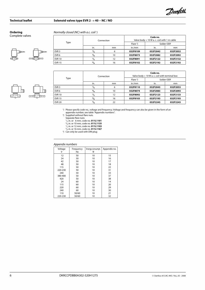
OrderingComplete valves
1) Please specify code no ., voltage and frequency . Voltage and frequency can also be given in the form of an appendix number, see table "Appendix numbers" .
2) Supplied without flare nuts . Separate flare nuts: 1/4 in . or 6 mm, code no . 011L1101 3/8 in . or 10 mm, code no . 011L1135 1/2 in . or 12 mm, code no . 011L1103 5/8 in . or 16 mm, code no . 011L11673) Can only be used with DIN plug
VoltageV
FrequencyHz
Energy consumpt .W
Appendix no .
12 24 42 48115
220-230240
380-400420 24115220240110
220-230
50505050505050505060606060
50/6050/60
101010101010101010101010101010
151617182231333738142029302132
Appendix numbers
TypeConnection
Code no.Valve body + 10 W a . c . coil with terminal box
Flare 2) Solder ODF
in . mm in ./mm in . mm
EVR 3 1/4 6 032F8110 032F2043 032F2053
EVR 6 3/8 10 032F8074 032F2083 032F2093
EVR 10 1/2 12 032F8092 032F2123 032F2133
EVR 15 5/8 16 032F8103 032F2193 032F2193
EVR 20 7/8 22 032F2243 032F2243
Normally closed (NC) with a.c. coil 1)
Danfoss A/S (AC-AKC / frz, 05 - 2008 DKRCCPDBB0A302-520H1275 7
Technical leaflet Solenoid valves type EVR 2 → 40 − NC / NO
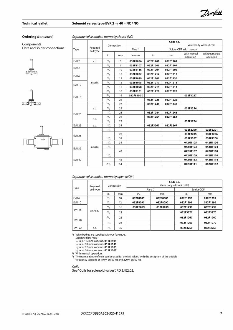
Ordering (continued)
ComponentsFlare and solder connections
1) Valve bodies are supplied without flare nuts . Separate flare nuts: 1/4 in . or 6 mm, code no . 011L1101 3/8 in . or 10 mm, code no . 011L1135 1/2 in . or 12 mm, code no . 011L1103 5/8 in . or 16 mm, code no . 011L11672) With manual operation . 3) The normal range of coils can be used for the NO valves, with the exception of the double frequency versions of 110 V, 50/60 Hz and 220 V, 50/60 Hz .
CoilsSee "Coils for solenoid valves", RD .3J .E2 .02 .
TypeRequiredcoil type
ConnectionCode no.
Valve body without coil
Flare 1) Solder ODF With manual
in . mm in ./mm in . mm With manual
operationWithout manual
operation
EVR 2 a .c . 1/4 6 032F8056 032F1201 032F1202
EVR 3
a .c ./d .c .
1/4 6 032F8107 032F1206 032F12073/8 10 032F8116 032F1204 032F1208
EVR 63/8 10 032F8072 032F1212 032F12131/2 12 032F8079 032F1209 032F1236
EVR 101/2 12 032F8095 032F1217 032F12185/8 16 032F8098 032F1214 032F1214
EVR 15
5/8 16 032F8101 032F1228 032F12285/8 16 032F8100 2) 032F12277/8 22 032F1225 032F1225
EVR 20
a .c .
7/8 22 032F1240 032F12407/8 22 032F1254
11/8 28 032F1244 032F1245
d .c .7/8 22 032F1264 032F12647/8 22 032F1274
EVR 22 a .c . 13/8 35 032F3267 032F3267
EVR 25
a .c ./d .c .
11/8 032F2200 032F2201
28 032F2205 032F2206
13/8 35 032F2207 032F2208
EVR 32
13/8 35 042H1105 042H1106
15/8 042H1103 042H1104
42 042H1107 042H1108
EVR 40
15/8 042H1109 042H1110
42 042H1113 042H1114
21/8 54 042H1111 042H1112
Separate valve bodies, normally closed (NC)
TypeRequiredcoil type
ConnectionCode no.
Valve body without coil 3)
Flare 1) Solder ODF
in . mm in . mm in . mm
EVR 6
a .c ./d .c .
3/8 10 032F8085 032F8085 032F1290 032F1295
EVR 10 1/2 12 032F8090 032F8090 032F1291 032F1296
EVR 155/8 16 032F8099 032F8099 032F1299 032F1299
7/8 22 032F3270 032F3270
EVR 207/8 22 032F1260 032F1260
11/8 28 032F1269 032F1279
EVR 22 a .c . 13/8 35 032F3268 032F3268
Separate valve bodies, normally open (NO) 3)

8 DKRCCPDBB0A302-520H1275 Danfoss A/S (AC-AKS / frz),, 05 - 2008
Technical leaflet Solenoid valves type EVR 2 → 40 − NC / NO
Ordering (continued)
ComponentsFlare and solder connections
Separate valve bodies, normally closed (NC)
Type Require coil type Connection
Code no.Valve body + gaskets +bolts;
without coil and flanges
Without manual operation
Without manual operation
EVR 15 a .c ./d .c .
Flanges
032F1234 032F1224
EVR 20a .c . 032F1253 032F1243
d .c . 032F1273 032F1263
CoilsSee "Coils for solenoid valves", RD .3J .E2 .02 .
Flange sets
Valve typeConnection
Code no.
Solder Weid
in . mm in . mm in .
EVR 15
1/2 027N11155/8 16 027L1117 027L11163/4 027N11207/8 22 027L1123 027L1122
EVR 20
3/4 027N12207/8 22 027L1223 027L1222
1 027N1225
11/8 28 027L1229 027L1228
Accessories
ExampleEVR 15 without manual operation,code no . 032F1224
+ 1/2 in . weld flange set,code no . 027N1115
+ coil with termfnal box, 220 V, 50 Hz,code no . 018F6701(See "Coils for solenoid valves", RD .3J .E2 .02 .) .
Description Code no.
Mounting bracket for EVR 2, 3, 6 and 10 032F0197
Strainer FA for direct mounting See "FA"
Danfoss A/S (AC-AKC / frz, 05 - 2008 DKRCCPDBB0A302-520H1275 9
Technical leaflet Solenoid valves type EVR 2 → 40 − NC / NO
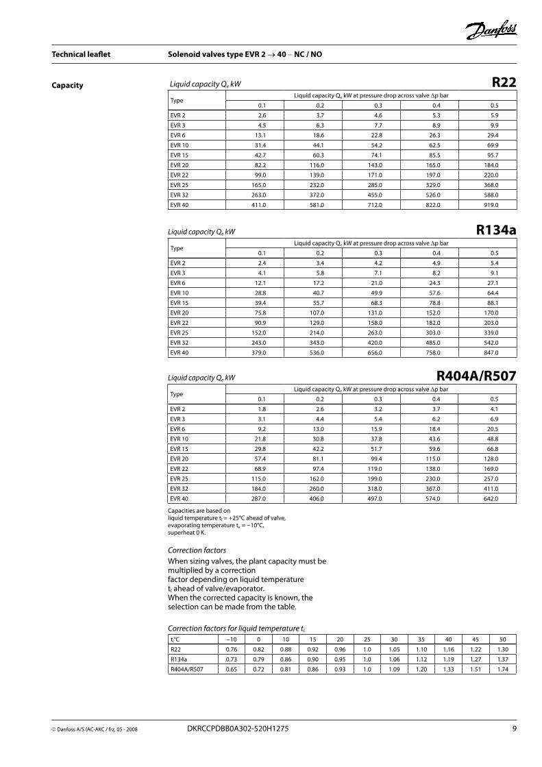
R22Liquid capacity Qe kW
R134a
Capacities are based on liquid temperature tl = +25°C ahead of valve, evaporating temperature te = −10°C, superheat 0 K .
Capacity
When sizing valves, the plant capacity must be multiplied by a correction factor depending on liquid temperature tl ahead of valve/evaporator .When the corrected capacity is known, the selection can be made from the table .
TypeLiquid capacity Qe kW at pressure drop across valve ∆p bar
0 .1 0 .2 0 .3 0 .4 0 .5
EVR 2 2 .6 3 .7 4 .6 5 .3 5 .9
EVR 3 4 .5 6 .3 7 .7 8 .9 9 .9
EVR 6 13 .1 18 .6 22 .8 26 .3 29 .4
EVR 10 31 .4 44 .1 54 .2 62 .5 69 .9
EVR 15 42 .7 60 .3 74 .1 85 .5 95 .7
EVR 20 82 .2 116 .0 143 .0 165 .0 184 .0
EVR 22 99 .0 139 .0 171 .0 197 .0 220 .0
EVR 25 165 .0 232 .0 285 .0 329 .0 368 .0
EVR 32 263 .0 372 .0 455 .0 526 .0 588 .0
EVR 40 411 .0 581 .0 712 .0 822 .0 919 .0
Correction factors
tl°C −10 0 10 15 20 25 30 35 40 45 50
R22 0 .76 0 .82 0 .88 0 .92 0 .96 1 .0 1 .05 1 .10 1 .16 1 .22 1 .30
R134a 0 .73 0 .79 0 .86 0 .90 0 .95 1 .0 1 .06 1 .12 1 .19 1 .27 1 .37
R404A/R507 0 .65 0 .72 0 .81 0 .86 0 .93 1 .0 1 .09 1 .20 1 .33 1 .51 1 .74
Correction factors for liquid temperature tl
Liquid capacity Qe kW
TypeLiquid capacity Qe kW at pressure drop across valve ∆p bar
0 .1 0 .2 0 .3 0 .4 0 .5
EVR 2 2 .4 3 .4 4 .2 4 .9 5 .4
EVR 3 4 .1 5 .8 7 .1 8 .2 9 .1
EVR 6 12 .1 17 .2 21 .0 24 .3 27 .1
EVR 10 28 .8 40 .7 49 .9 57 .6 64 .4
EVR 15 39 .4 55 .7 68 .3 78 .8 88 .1
EVR 20 75 .8 107 .0 131 .0 152 .0 170 .0
EVR 22 90 .9 129 .0 158 .0 182 .0 203 .0
EVR 25 152 .0 214 .0 263 .0 303 .0 339 .0
EVR 32 243 .0 343 .0 420 .0 485 .0 542 .0
EVR 40 379 .0 536 .0 656 .0 758 .0 847 .0
R404A/R507Liquid capacity Qe kW
TypeLiquid capacity Qe kW at pressure drop across valve ∆p bar
0 .1 0 .2 0 .3 0 .4 0 .5
EVR 2 1 .8 2 .6 3 .2 3 .7 4 .1
EVR 3 3 .1 4 .4 5 .4 6 .2 6 .9
EVR 6 9 .2 13 .0 15 .9 18 .4 20 .5
EVR 10 21 .8 30 .8 37 .8 43 .6 48 .8
EVR 15 29 .8 42 .2 51 .7 59 .6 66 .8
EVR 20 57 .4 81 .1 99 .4 115 .0 128 .0
EVR 22 68 .9 97 .4 119 .0 138 .0 169 .0
EVR 25 115 .0 162 .0 199 .0 230 .0 257 .0
EVR 32 184 .0 260 .0 318 .0 367 .0 411 .0
EVR 40 287 .0 406 .0 497 .0 574 .0 642 .0

10 DKRCCPDBB0A302-520H1275 Danfoss A/S (AC-AKS / frz),, 05 - 2008
Technical leaflet Solenoid valves type EVR 2 → 40 − NC / NO
Type Pressure drop
∆p barSuction vapour capacity Qe kW at evaporating temperature te °C
–40 –30 –20 –10 0 +10
EVR 60 .1 0 .150 .2
0 .73 0 .87 0 .98
0 .94 1 .1 1 .3
1 .2 1 .4 1 .6
1 .5 1 .8 2 .0
1 .8 2 .2 2 .5
2 .1 2 .6 3 .0
EVR 100 .1 0 .150 .2
1 .7 2 .1 2 .3
2 .2 2 .7 3 .1
2 .9 3 .4 3 .9
3 .5 4 .3 4 .8
4 .3 5 .2 6 .0
5 .1 6 .2 7 .1
EVR 150 .1 0 .150 .2
2 .3 2 .8 3 .2
3 .1 3 .7 4 .2
4 .0 4 .7 5 .3
4 .8 5 .9 6 .6
5 .8 7 .1 8 .2
6 .9 8 .5 9 .8
EVR 200 .1 0 .150 .2
4 .6 5 .4 6 .1
5 .9 7 .1 8 .1
7 .6 9 .110 .3
9 .311 .412 .7
11 .213 .915 .9
13 .316 .718 .8
EVR 220 .1 0 .150 .2
5 .5 6 .5 7 .3
7 .1 8 .5 9 .7
9 .110 .712 .3
11 .213 .715 .2
13 .416 .419 .0
16 .020 .022 .6
EVR 250 .1 0 .150 .2
9 .1 10 .9 12 .2
11 .8 14 .2 16 .1
15 .217 .920 .4
18 .622 .825 .3
22 .427 .431 .7
26 .632 .637 .6
EVR 320 .1 0 .150 .2
14 .6 17 .4 19 .6
18 .9 22 .7 25 .7
24 .328 .832 .6
29 .836 .540 .5
35 .843 .850 .7
42 .652 .260 .2
EVR 400 .1 0 .150 .2
22 .8 27 .2 30 .5
29 .5 35 .4 40 .2
38 .145 .051 .0
46 .557 .063 .3
56 .068 .679 .2
66 .581 .594 .0
R22Suction vapour capacity Qe
Capacity(continued)
Capacities are based on liquid temperature tl = +25°C ahead of evaporator . The table values refer to the evaporator capacity and are given as a function of evaporating temperature te and pressure drop ∆p across valve . Capacities are based on dry, saturated vapour ahead of valve .During operation with superheated vapour ahead of valve, the capacities are reduced by 4% for each 10K superheat .
Correction factorsWhen sizing valves, the evaporator capacity must be multiplied by a correction factor depending on liquid temperature tl ahead of expansion valve .When the corrected capacity is known, the selection can be made from the table .
tl°C −10 0 10 15 20 25 30 35 40 45 50
R22 0 .76 0 .82 0 .88 0 .92 0 .96 1 .0 1 .05 1 .10 1 .16 1 .22 1 .30
Correction factorsWhen sizing valves, the plant capacity must be multiplied by a correction factor depending on liquid temperature tl ahead of valve/evaporator .When the corrected capacity is known, the selection can be made from the table .
tl°C −10 0 10 15 20 25 30 35 40 45 50
R407C 0 .71 0 .78 0 .85 0 .89 0 .94 1 .0 1 .06 1 .14 1 .23 1 .33 1 .46
Correction factors based on liquid temperature tl
Capacities are based on liquid temperature tl = +25°C ahead of valve, evaporating temperature te = −10°C, and superheat 0 K .
Correction factors for liquid temperature tl
R407CLiquid capacity Qe kW
TypeLiquid capacity Qe kW at pressure drop across valve ∆p bar
0 .1 0 .2 0 .3 0 .4 0 .5
EVR 2 2 .4 3 .4 4 .3 5 .0 5 .3
EVR 3 4 .2 5 .9 7 .2 8 .4 9 .3
EVR 6 12 .3 17 .5 21 .4 24 .7 27 .6
EVR 10 29 .5 41 .5 50 .9 58 .7 65 .7
EVR 15 40 .1 56 .7 69 .7 80 .4 90 .0
EVR 20 77 .0 109 .0 134 .0 155 .0 172 .0
EVR 22 93 .1 130 .0 161 .0 185 .2 207 .0
EVR 25 155 .0 218 .0 268 .0 309 .0 346 .0
EVR 32 247 .0 350 .0 428 .0 494 .0 553 .0
EVR 40 386 .0 546 .0 669 .0 773 .0 864 .0

Danfoss A/S (AC-AKC / frz, 05 - 2008 DKRCCPDBB0A302-520H1275 11
Technical leaflet Solenoid valves type EVR 2 → 40 − NC / NO
Capacity(continued)
R404A/R507Suction vapour capacity Qe kW
tl°C −10 0 10 15 20 25 30 35 40 45 50
R134a 0 .73 0 .79 0 .86 0 .90 0 .95 1 .0 1 .06 1 .12 1 .19 1 .27 1 .37
R404A/R507 0 .65 0 .72 0 .81 0 .86 0 .93 1 .0 1 .09 1 .20 1 .33 1 .51 1 .74
Correction factors based on liquid temperature tl
Correction factorsWhen sizing valves, the plant capacity must be multiplied by a correction factor depending on liquid temperature tl ahead of valve/evaporator .When the corrected capacity is known, the selection can be made from the table .
Capacities are based on liquid temperature tl = +25°C ahead of evaporator . The table values refer to the evaporator capacity and are given as a function of evaporating temperature te and pressure drop ∆p across valve . Capacities are based on dry, saturated vapour ahead of valve .During operation with superheated vapour ahead of valve, the capacities are reduced by 4% for each 10K superheat .
Suction vapour capacity Qe R134aType
Pressure drop across valve ∆p bar
Suction vapour capacity Qe kW at evaporating temperature te °C
–40 –30 –20 –10 0 +10
EVR 60 .1
0 .150 .2
0 .46 0 .53 0 .58
0 .73 0 .87 0 .98
0 .841 .01 .1
1 .1 1 .31 .5
1 .41 .71 .9
1 .72 .02 .4
EVR 100 .1
0 .150 .2
1 .1 1 .3 1 .4
1 .7 2 .1 2 .3
2 .02 .42 .7
2 .63 .13 .5
3 .34 .04 .5
4 .04 .95 .7
EVR 150 .1
0 .150 .2
1 .5 1 .7 1 .9
2 .3 2 .8 3 .2
2 .73 .33 .7
3 .64 .24 .8
4 .55 .56 .1
5 .56 .77 .8
EVR 200 .1
0 .150 .2
2 .9 3 .3 3 .7
4 .6 5 .4 6 .1
5 .36 .37 .1
7 .08 .19 .3
8 .610 .611 .7
10 .613 .015 .0
EVR 220 .1
0 .150 .2
3 .4 4 .0 4 .4
5 .56 .57 .3
6 .37 .58 .5
8 .39 .7
11 .1
10 .312 .714 .0
12 .715 .517 .9
EVR 250 .1
0 .150 .2
5 .8 6 .6 7 .3
9 .110 .912 .2
10 .512 .514 .1
13 .916 .318 .5
17 .221 .123 .4
21 .125 .929 .9
EVR 320 .1
0 .150 .2
9 .3 10 .6 11 .7
14 .617 .419 .6
16 .820 .022 .6
22 .226 .129 .6
27 .733 .837 .4
33 .841 .447 .4
EVR 400 .1
0 .150 .2
14 .5 16 .5 18 .3
22 .827 .230 .5
26 .331 .335 .3
34 .840 .846 .3
43 .352 .858 .5
52 .864 .874 .8
TypePressure drop
across valve∆p barSuction vapour capacity Qe kW at evaporating temperature te °C
–40 –30 –20 –10 0 +10
EVR 60 .1 0 .150 .2
0 .62 0 .73 0 .82
0 .8 0 .97
1 .1
1 .1 1 .3 1 .4
1 .31 .61 .8
1 .62 .02 .3
2 .02 .42 .8
EVR 100 .1 0 .150 .2
1 .5 1 .72 .0
1 .9 2 .32 .6
2 .5 3 .03 .4
3 .23 .94 .3
3 .94 .85 .5
4 .75 .86 .7
EVR 150 .1 0 .150 .2
2 .0 2 .4 2 .7
2 .6 3 .2 3 .6
3 .5 4 .1 4 .7
4 .35 .35 .9
5 .36 .57 .5
6 .47 .99 .1
EVR 200 .1 0 .150 .2
3 .9 4 .6 5 .2
5 .0 6 .1 6 .9
6 .7 7 .9 9 .0
8 .310 .211 .4
10 .212 .514 .4
12 .315 .217 .5
EVR 220 .1 0 .150 .2
4 .6 5 .5 6 .2
6 .0 7 .3 8 .3
8 .0 9 .5
10 .8
10 .012 .213 .6
12 .215 .017 .3
14 .818 .221 .0
EVR 250 .1 0 .150 .2
7 .7 9 .1
10 .3
10 .1 12 .1 13 .8
13 .3 15 .8 18 .0
16 .620 .422 .7
20 .425 .028 .8
24 .630 .335 .0
EVR 320 .1 0 .150 .2
12 .3 14 .6 16 .5
16 .2 19 .4 22 .0
21 .3 25 .3 28 .8
26 .632 .636 .3
32 .640 .046 .1
39 .448 .556 .0
EVR 400 .1 0 .150 .2
19 .3 22 .8 25 .8
25 .3 30 .3 34 .5
33 .3 39 .5 45 .0
41 .551 .056 .8
51 .062 .572 .1
61 .575 .687 .5

12 DKRCCPDBB0A302-520H1275 Danfoss A/S (AC-AKS / frz),, 05 - 2008
Technical leaflet Solenoid valves type EVR 2 → 40 − NC / NO
Capacities are based on liquid temperature tl = +25°C ahead of evaporator .The table values refer to the evaporator capacity and are given as a function of evaporating temperature te and pressure drop ∆p across valve .Capacities are based on dry, saturated vapour ahead of valve .During operation with superheated vapour ahead of valve, the capacities are reduced by 4% for each 10K superheat .
Correction factorsWhen sizing valves, the evaporator capacity must be multiplied by a correction factor depending on liquid temperature tl ahead of expansion valve . When the corrected capacity is known, the selection can be made from the table .
R407CType
Pressure drop across valve∆p bar
Suction vapour capacity Qe kW at evaporating temperature te °C
–40 –30 –20 –10 0 +10
EVR 6 0 .10 .150 .2
0 .610 .720 .81
0 .810 .951 .1
1 .11 .31 .4
1 .41 .71 .8
1 .72 .12 .4
2 .02 .52 .9
EVR 100 .10 .150 .2
1 .41 .71 .9
1 .92 .32 .7
2 .63 .03 .5
3 .24 .04 .4
4 .04 .95 .6
4 .96 .06 .9
EVR 150 .10 .150 .2
1 .92 .32 .7
2 .73 .23 .6
3 .64 .24 .7
4 .45 .46 .1
5 .56 .77 .7
6 .78 .29 .5
EVR 200 .10 .150 .2
3 .84 .55 .1
5 .16 .17 .0
6 .88 .19 .2
8 .610 .511 .7
10 .513 .114 .9
12 .916 .218 .2
EVR 220 .10 .150 .2
4 .65 .46 .1
6 .17 .38 .3
8 .19 .5
11 .0
10 .312 .614 .0
12 .615 .417 .9
15 .519 .421 .9
EVR 250 .10 .150 .2
7 .6 9 .110 .1
10 .212 .213 .9
13 .515 .918 .2
17 .121 .023 .3
21 .125 .829 .8
25 .831 .636 .5
EVR 320 .10 .150 .2
12 .114 .416 .3
16 .319 .522 .1
21 .625 .629 .0
27 .433 .637 .3
33 .741 .247 .7
41 .350 .658 .4
EVR 400 .10 .150 .2
18 .922 .625 .3
25 .430 .434 .6
33 .940 .145 .4
42 .852 .458 .2
52 .664 .574 .4
64 .579 .191 .2
tl°C −10 0 10 15 20 25 30 35 40 45 50
R407C 0 .71 0 .78 0 .85 0 .89 0 .94 1 .0 1 .06 1 .14 1 .23 1 .33 1 .46
Correction factors based on liquid temperature tl
Capacity(continued)
Hot gas defrostingWith hot gas defrosting it is not normally possible to select a valve from condensing temperature tc
and evaporating temperature te .This is because the pressure in the evaporator as a rule quickly rises to a value near that of the condensing pressure . It remains at this value until the defrosting is finished .In most cases therefore, the valve will be selected from condensing temperature tc and pressure drop ∆p across the valve, as shown in the example for heat recovery .
Heat recoveryThe following is given:Refrigerant = R22Evaporating temperature te = – 30°CCondensing temperature tc = + 40°CHot gas temperature ahead of valve th = + 85°CHeat recovery condenser yield Qh = 8 kW
The capacity table for 22 with tc = + 40°C gives the the capacity for an EVR 10 as 8 .9 kW, when pressure drop ∆p is 0 .2 bar .The correction factor for te = – 30°C is given in the table as 0 .94 .
The correction for hot gas temperatureth = + 85°C has been calculated as 4% which corresponds to a factor of 1 .04 .
Qh must be corrected with factors found:With ∆p = 0 .2 bar isQh = 8 .9 x 0 .94 x 1 .04 = 8 .7 kW .With ∆p = 0 .1 bar, Qh becomes only6 .3 x 0 .94 x 1 .04 = 6 .2 kW .
An EVR 6 would also be able to give the required capacity, but with ∆p at approx . 1 bar .The EVR 6 is therefore too small .
The EVR is so large that it is doubtful whether the necessary ∆p of apprx . 0 .1 bar could be obtained .An EVR 15 would therefore be too large .
Result: An EVR 10 is the correct valve for the given conditions .

Danfoss A/S (AC-AKC / frz, 05 - 2008 DKRCCPDBB0A302-520H1275 13
Technical leaflet Solenoid valves type EVR 2 → 40 − NC / NO
Capacity(continued)
R22Hot gas capacity Qh kW
TypePressure drop across valve
∆p bar
Hot gas capacity Qh kW
Evaporating temp . te=-10°C . Hot gas temp . th=tc +25°C . Subcooling ∆tsub =4K
Condensing temperature tc °C
+20 +30 +40 +50 +60
EVR 2
0 .10 .20 .40 .81 .6
0 .47 0 .67 0 .96 1 .32 1 .87
0 .50 0 .71 1 .02 1 .37 1 .99
0 .53 0 .75 1 .07 1 .48 2 .08
0 .54 0 .77 1 .10 1 .57 2 .16
0 .55 0 .78 1 .11 1 .59 2 .19
EVR 3
0 .10 .20 .40 .81 .6
0 .80 1 .14 1 .63 2 .23 3 .15
0 .85 1 .20 1 .72 2 .31 3 .35
0 .89 1 .26 1 .80 2 .49 3 .52
0 .92 1 .30 1 .85 2 .65 3 .64
0 .93 1 .32 1 .87 2 .68 3 .69
EVR 6
0 .10 .20 .40 .81 .6
2 .4 3 .4 4 .8 6 .6 9 .3
2 .5 3 .6 5 .1 6 .8 9 .9
2 .6 3 .7 5 .3 7 .4 10 .4
2 .7 3 .4 5 .5 7 .9 10 .8
2 .8 3 .9 5 .6 7 .9 10 .9
EVR 10
0 .10 .20 .40 .81 .6
5 .6 8 .0 11 .4 15 .7 22 .2
6 .0 8 .5 12 .1 16 .2 23 .6
6 .3 8 .9 12 .7 17 .5 24 .8
6 .5 9 .2 13 .0 18 .7 25 .6
6 .5 9 .3 13 .2 18 .9 26 .0
EVR 15
0 .10 .20 .40 .81 .6
7 .7 11 .0 15 .7 21 .5 30 .3
8 .2 11 .6 16 .6 22 .2 32 .3
8 .6 12 .1 17 .3 24 .0 33 .9
8 .8 12 .5 17 .8 25 .5 35 .0
8 .9 12 .7 18 .0 25 .9 35 .5
EVR 20
0 .10 .20 .40 .81 .6
14 .8 21 .1 30 .0 41 .3 58 .3
15 .7 22 .3 31 .9 42 .7 62 .1
16 .5 23 .4 33 .3 46 .2 65 .2
17 .0 24 .1 34 .3 49 .1 67 .4
17 .2 24 .4 34 .7 49 .6 68 .4
EVR 22
0 .10 .20 .40 .81 .6
17 .8 25 .3 36 .1 49 .5 70 .0
18 .8 26 .8 38 .3 51 .2 74 .5
19 .7 28 .0 40 .0 55 .4 78 .2
20 .4 28 .9 41 .2 58 .9 80 .8
20 .6 29 .3 41 .6 59 .5 82 .0
EVR 25
0 .10 .20 .40 .81 .6
29 .6 42 .1 60 .2 82 .5 117 .0
31 .4 44 .6 63 .8 87 .9 124 .0
32 .9 46 .7 66 .6 92 .3 130 .0
34 .0 48 .2 68 .6 98 .2 135 .0
34 .4 48 .8 69 .4 99 .2 137 .0
EVR 32
0 .10 .20 .40 .81 .6
47 .4 67 .4 96 .3 132 .0 187 .0
50 .2 71 .4 102 .0 140 .0 199 .0
52 .6 74 .7 107 .0 148 .0 209 .0
54 .4 77 .1 110 .0 157 .0 216 .0
55 .0 78 .1 111 .0 159 .0 219 .0
EVR 40
0 .10 .20 .40 .81 .6
74 .0 105 .0 151 .0 206 .0 291 .0
78 .5 112 .0 159 .0 222 .0 310 .0
82 .3 117 .0 167 .0 231 .0 326 .0
85 .0 121 .0 172 .0 246 .0 337 .0
86 .0 122 .0 174 .0 248 .0 342 .0
An increase in hot gas temperature th of 10K, based on th = tc +25°C, reduces valve capacity approx . 2% and vice versa .
A change in evaporating temperature te changes valve capacity; see correction factor table below .
Correction factorsWhen sizing valves, the table value must be multiplied by a correction factor depending on evaporating temperature te .
te °C −40 −30 −20 −10 0 +10
R22 0 .90 0 .94 0 .97 1 .0 1 .03 1 .05
Correction factors for evaporating temperatur te
14 DKRCCPDBB0A302-520H1275 Danfoss A/S (AC-AKS / frz),, 05 - 2008
Technical leaflet Solenoid valves type EVR 2 → 40 − NC / NO
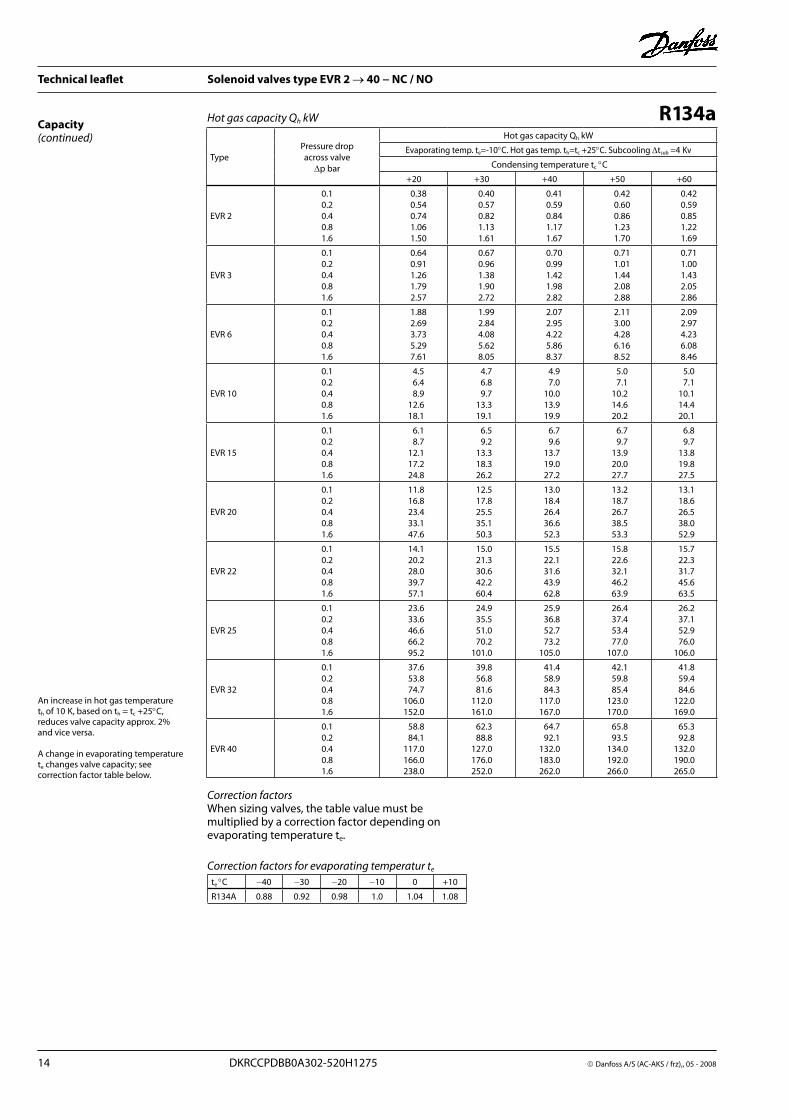
R134aHot gas capacity Qh kWCapacity(continued)
TypePressure drop across valve
∆p bar
Hot gas capacity Qh kW
Evaporating temp . te=-10°C . Hot gas temp . th=tc +25°C . Subcooling ∆tsub =4Kv
Condensing temperature tc °C
+20 +30 +40 +50 +60
EVR 2
0 .10 .20 .40 .81 .6
0 .38 0 .54 0 .74 1 .06 1 .50
0 .40 0 .57 0 .82 1 .13 1 .61
0 .41 0 .59 0 .84 1 .17 1 .67
0 .42 0 .60 0 .86 1 .23 1 .70
0 .42 0 .59 0 .85 1 .22 1 .69
EVR 3
0 .10 .20 .40 .81 .6
0 .64 0 .91 1 .26 1 .79 2 .57
0 .67 0 .96 1 .38 1 .90 2 .72
0 .70 0 .99 1 .42 1 .98 2 .82
0 .71 1 .01 1 .44 2 .08 2 .88
0 .71 1 .00 1 .43 2 .05 2 .86
EVR 6
0 .10 .20 .40 .81 .6
1 .88 2 .69 3 .73 5 .29 7 .61
1 .99 2 .84 4 .08 5 .62 8 .05
2 .07 2 .95 4 .22 5 .86 8 .37
2 .11 3 .00 4 .28 6 .16 8 .52
2 .09 2 .97 4 .23 6 .08 8 .46
EVR 10
0 .10 .20 .40 .81 .6
4 .5 6 .4 8 .9 12 .6 18 .1
4 .7 6 .8 9 .7 13 .3 19 .1
4 .9 7 .0 10 .0 13 .9 19 .9
5 .0 7 .1 10 .2 14 .6 20 .2
5 .0 7 .1 10 .1 14 .4 20 .1
EVR 15
0 .10 .20 .40 .81 .6
6 .1 8 .7 12 .1 17 .2 24 .8
6 .5 9 .2 13 .3 18 .3 26 .2
6 .7 9 .6 13 .7 19 .0 27 .2
6 .7 9 .7 13 .9 20 .0 27 .7
6 .8 9 .7 13 .8 19 .8 27 .5
EVR 20
0 .10 .20 .40 .81 .6
11 .8 16 .8 23 .4 33 .1 47 .6
12 .5 17 .8 25 .5 35 .1 50 .3
13 .0 18 .4 26 .4 36 .6 52 .3
13 .2 18 .7 26 .7 38 .5 53 .3
13 .1 18 .6 26 .5 38 .0 52 .9
EVR 22
0 .10 .20 .40 .81 .6
14 .1 20 .2 28 .0 39 .7 57 .1
15 .0 21 .3 30 .6 42 .2 60 .4
15 .5 22 .1 31 .6 43 .9 62 .8
15 .8 22 .6 32 .1 46 .2 63 .9
15 .7 22 .3 31 .7 45 .6 63 .5
EVR 25
0 .10 .20 .40 .81 .6
23 .6 33 .6 46 .6 66 .2 95 .2
24 .9 35 .5 51 .0 70 .2 101 .0
25 .9 36 .8 52 .7 73 .2 105 .0
26 .4 37 .4 53 .4 77 .0 107 .0
26 .2 37 .1 52 .9 76 .0 106 .0
EVR 32
0 .10 .20 .40 .81 .6
37 .6 53 .8 74 .7 106 .0 152 .0
39 .8 56 .8 81 .6 112 .0 161 .0
41 .4 58 .9 84 .3 117 .0 167 .0
42 .1 59 .8 85 .4 123 .0 170 .0
41 .8 59 .4 84 .6 122 .0 169 .0
EVR 40
0 .10 .20 .40 .81 .6
58 .8 84 .1 117 .0 166 .0 238 .0
62 .3 88 .8 127 .0 176 .0 252 .0
64 .7 92 .1 132 .0 183 .0 262 .0
65 .8 93 .5 134 .0 192 .0 266 .0
65 .3 92 .8 132 .0 190 .0 265 .0
An increase in hot gas temperature th of 10K, based on th = tc +25°C, reduces valve capacity approx . 2% and vice versa .
A change in evaporating temperature te changes valve capacity; see correction factor table below .
Correction factorsWhen sizing valves, the table value must be multiplied by a correction factor depending on evaporating temperature te .
te °C −40 −30 −20 −10 0 +10
R134A 0 .88 0 .92 0 .98 1 .0 1 .04 1 .08
Correction factors for evaporating temperatur te

Danfoss A/S (AC-AKC / frz, 05 - 2008 DKRCCPDBB0A302-520H1275 15
Technical leaflet Solenoid valves type EVR 2 → 40 − NC / NO
R404A/R507Hot gas capacity Qh kWCapacity(continued)
TypePressure drop across valve
∆p bar
Hot gas capacity Qh kW
Evaporating temp . te=-10°C . Hot gas temp . th=tc +25°C . Subcooling ∆tsub =4K
Condensing temperature tc °C
+20 +30 +40 +50 +60
EVR 2
0 .10 .20 .40 .81 .6
0 .43 0 .61 0 .87 1 .19 1 .68
0 .44 0 .62 0 .87 1 .21 1 .70
0 .43 0 .61 0 .87 1 .21 1 .69
0 .40 0 .58 0 .82 1 .19 1 .62
0 .37 0 .53 0 .75 1 .07 1 .48
EVR 3
0 .10 .20 .40 .81 .6
0 .73 1 .03 1 .46 2 .01 2 .83
0 .74 1 .04 1 .48 2 .04 2 .87
0 .73 1 .03 1 .47 2 .03 2 .84
0 .69 0 .98 1 .39 2 .00 2 .74
0 .63 0 .89 1 .27 1 .81 2 .50
EVR 6
0 .10 .20 .40 .81 .6
2 .16 3 .03 4 .34 5 .94 8 .37
2 .18 3 .08 4 .38 6 .05 8 .52
2 .15 3 .05 4 .35 6 .02 8 .43
2 .05 2 .90 4 .13 5 .92 8 .10
1 .86 2 .64 3 .76 5 .37 7 .40
EVR 10
0 .10 .20 .40 .81 .6
5 .1 7 .2 10 .3 14 .1 19 .9
5 .2 7 .3 10 .4 14 .4 20 .3
5 .1 7 .3 10 .3 14 .3 20 .0
4 .9 6 .9 9 .8 14 .1 19 .2
4 .4 6 .3 8 .9
12 .8 17 .6
EVR 15
0 .10 .20 .40 .81 .6
7 .0 9 .9 14 .1 19 .3 27 .2
7 .1 10 .0 14 .3 19 .7 27 .7
7 .0 9 .9 14 .2 19 .6 27 .6
6 .7 9 .4 13 .4 19 .2 26 .3
6 .1 8 .6 12 .2 17 .5 24 .1
EVR 20
0 .10 .20 .40 .81 .6
13 .4 18 .9 27 .1 37 .1 52 .4
13 .7 19 .2 27 .4 37 .8 53 .3
13 .5 19 .1 27 .2 37 .7 52 .6
12 .8 18 .2 25 .8 37 .0 50 .6
11 .6 16 .5 23 .5 33 .6 46 .2
EVR 22
0 .10 .20 .40 .81 .6
16 .1 22 .7 32 .5 44 .5 62 .8
16 .4 23 .1 32 .9 45 .4 64 .0
16 .1 22 .9 32 .7 45 .2 63 .2
15 .4 21 .8 31 .0 44 .4 60 .8
14 .0 19 .8 28 .2 40 .3 55 .5
EVR 25
0 .10 .20 .40 .81 .6
26 .8 37 .9 54 .2 74 .2 105 .0
27 .4 38 .4 54 .9 75 .6 107 .0
26 .9 38 .2 54 .5 75 .3 105 .0
25 .6 36 .3 51 .7 74 .0 101 .0
23 .3 33 .0 47 .0 67 .2 92 .5
EVR 32
0 .10 .20 .40 .81 .6
43 .0 60 .6 86 .7 119 .0 167 .0
43 .8 61 .4 87 .8 121 .0 171 .0
43 .0 61 .1 87 .2 120 .0 168 .0
40 .9 58 .1 82 .7 118 .0 162 .0
37 .3 52 .8 75 .2 107 .0 148 .0
EVR 40
0 .10 .20 .40 .81 .6
67 .0 94 .8 136 .0 186 .0 262 .0
68 .5 96 .0 137 .0 189 .0 266 .0
67 .3 95 .5 136 .0 188 .0 263 .0
64 .0 90 .8 129 .0 185 .0 253 .0
58 .3 82 .5 117 .0 168 .0 231 .0
Correction factorsWhen sizing valves, the table value must be multiplied by a correction factor depending on evaporating temperature te .
An increase in hot gas temperature th of 10K, based on th = tc +25°C, reduces valve capacity approx . 2% and vice versa .
A change in evaporating temperature te changes valve capacity; see correction factor table below .
Correction factors for evaporating temperatur te
te °C −40 −30 −20 −10 0 +10
R440A/R507 0 .86 0 .88 0 .93 1 .0 1 .03 1 .07

16 DKRCCPDBB0A302-520H1275 Danfoss A/S (AC-AKS / frz),, 05 - 2008
Technical leaflet Solenoid valves type EVR 2 → 40 − NC / NO
R407CHot gas capacity Qh kWCapacity(continued)
TypePressure drop across valve
∆p bar
Hot gas capacity Qh kW
Evaporating temp . te=-10°C . Hot gas temp . th=tc +25°C . Subcooling ∆tsub =4K
Condensing temperature tc °C
+20 +30 +40 +50 +60
EVR 2
0 .10 .20 .40 .81 .6
0 .530 .751 .081 .482 .09
0 .550 .781 .121 .512 .19
0 .570 .801 .141 .582 .23
0 .560 .801 .141 .632 .25
0 .540 .761 .091 .562 .15
EVR 3
0 .10 .20 .40 .81 .6
0 .91 .281 .832 .503 .53
0 .941 .321 .892 .543 .69
0 .951 .351 .932 .663 .77
0 .961 .351 .922 .763 .79
0 .911 .291 .832 .633 .62
EVR 6
0 .10 .20 .40 .81 .6
2 .73 .85 .47 .4
10 .4
2 .84 .05 .67 .5
10 .9
2 .84 .05 .77 .9
11 .1
2 .83 .55 .78 .2
11 .2
2 .73 .85 .57 .7
10 .7
EVR 10
0 .10 .20 .40 .81 .6
6 .39 .0
12 .817 .624 .9
6 .69 .4
13 .317 .826 .0
6 .79 .5
13 .618 .726 .5
6 .89 .6
13 .519 .426 .6
6 .49 .1
12 .918 .525 .5
EVR 15
0 .10 .20 .40 .81 .6
8 .612 .317 .624 .133 .9
9 .012 .818 .324 .435 .5
9 .212 .918 .525 .736 .3
9 .213
18 .526 .536 .4
8 .712 .417 .625 .434 .8
EVR 20
0 .10 .20 .40 .81 .6
16 .623 .633 .646 .365 .3
17 .324 .535 .1
4768 .3
17 .725 .035 .649 .469 .8
17 .725 .135 .751 .170 .1
16 .923 .934 .048 .667 .0
EVR 22
0 .10 .20 .40 .81 .6
19 .928 .340 .455 .478 .4
20 .729 .542 .156 .382 .0
21 .130 .042 .859 .383 .7
21 .230 .142 .861 .3
84
20 .228 .740 .858 .380 .4
EVR 25
0 .10 .20 .40 .81 .6
33 .247 .267 .492 .4
131 .0
34 .549 .170 .296 .7
136 .4
35 .250 .071 .398 .8
139 .1
35 .450 .171 .3
102 .1140 .4
33 .747 .868 .097 .2
134 .3
EVR 32
0 .10 .20 .40 .81 .6
53 .175 .5
107 .9147 .8209 .4
55 .278 .5
112 .2154 .0218 .9
56 .379 .9
114 .5158 .4223 .6
56 .680 .2
114 .4163 .3224 .6
53 .976 .5
108 .8155 .8214 .6
EVR 40
0 .10 .20 .40 .81 .6
82 .9117 .6169 .1230 .7325 .9
86 .4123 .2174 .9244 .2341 .0
88 .1125 .2178 .7247 .2348 .8
88 .4125 .8178 .9255 .8350 .5
84 .3119 .6170 .5243 .0335 .2
Correction factorsWhen sizing valves, the table value must be multiplied by a correction factor depending on evaporating temperature te .
An increase in hot gas temperature th of 10K, based on th = tc +25°C, reduces valve capacity approx . 2% and vice versa .
A change in evaporating temperature te changes valve capacity; see correction factor table below .
Correction factors for evaporating temperatur te
te °C −40 −30 −20 −10 0 +10
R407C 0 .90 0 .94 0 .97 1 .0 1 .03 1 .05
Danfoss A/S (AC-AKC / frz, 05 - 2008 DKRCCPDBB0A302-520H1275 17
Technical leaflet Solenoid valves type EVR 2 → 40 − NC / NO
TypeHot gas
temperature th °C
Condensingtemperature
tc °C
Hot gas capacity Gh kg/s at pressure drop across valve ∆p bar
0 .5 1 2 3 4 5 6 7 8
EVR 2
+90
+25+35+45
0 .0050 .0060 .007
0 .0070 .0090 .01
0 .01 0 .0110 .013
0 .0110 .0130 .016
0 .0120 .0140 .017
0 .0120 .0150 .018
0 .0120 .0150 .019
0 .0120 .0150 .019
0 .0120 .0150 .02
EVR 3+25+35+45
0 .0090 .01 0 .012
0 .0120 .0140 .016
0 .0160 .0190 .022
0 .0190 .0220 .026
0 .02 0 .0240 .029
0 .02 0 .0250 .031
0 .02 0 .0260 .032
0 .02 0 .0260 .033
0 .02 0 .0260 .033
EVR 6+25+35+45
0 .0270 .0310 .035
0 .0370 .0430 .049
0 .0490 .0570 .066
0 .0550 .0670 .078
0 .0580 .0720 .086
0 .0590 .0750 .092
0 .0590 .0770 .095
0 .0590 .0770 .097
0 .0590 .0770 .098
EVR 10+25+35+45
0 .0640 .0740 .084
0 .0880 .1020 .116
0 .1160 .1370 .158
0 .1310 .1580 .185
0 .1390 .1720 .205
0 .14 0 .1790 .218
0 .14 0 .1820 .227
0 .14 0 .1820 .231
0 .14 0 .1820 .232
EVR 15+25+35+45
0 .0840 .0970 .11
0 .1160 .1340 .153
0 .1530 .18 0 .208
0 .1730 .2080 .244
0 .1820 .2260 .269
0 .1840 .2360 .287
0 .1840 .2390 .298
0 .1840 .2390 .304
0 .1840 .2390 .305
EVR 20+25+35+45
0 .1690 .1940 .22
0 .2310 .2670 .305
0 .3050 .3590 .415
0 .3460 .4160 .488
0 .3650 .4520 .539
0 .3680 .4720 .574
0 .3680 .4780 .597
0 .3680 .4780 .608
0 .3680 .4780 .611
EVR 22+25+35+45
0 .2030 .2790 .264
0 .2770 .32 0 .366
0 .3660 .4310 .498
0 .4150 .4990 .586
0 .4380 .5420 .647
0 .4420 .5660 .689
0 .4420 .5740 .716
0 .4420 .5740 .722
0 .4420 .5740 .733
EVR 25+25+35+45
0 .3310 .38 0 .431
0 .4530 .5240 .598
0 .5990 .7040 .814
0 .6770 .8160 .956
0 .7150 .8861 .056
0 .7220 .9251 .125
0 .7220 .9381 .169
0 .7220 .9381 .192
0 .7220 .9381 .197
EVR 32+25+35+45
0 .5390 .6190 .704
0 .7390 .8560 .978
0 .9761 .15 1 .329
1 .1061 .3311 .562
1 .1681 .4461 .723
1 .1791 .5091 .837
1 .5311 .909 1 .947 1 .955
EVR 40+25+35+45
0 .8430 .9681 .1
1 .1551 .3381 .528
1 .5251 .7982 .078
1 .7282 .08 2 .44
1 .8252 .26 2 .693
1 .8432 .3582 .87
2 .3932 .983 3 .043 3 .055
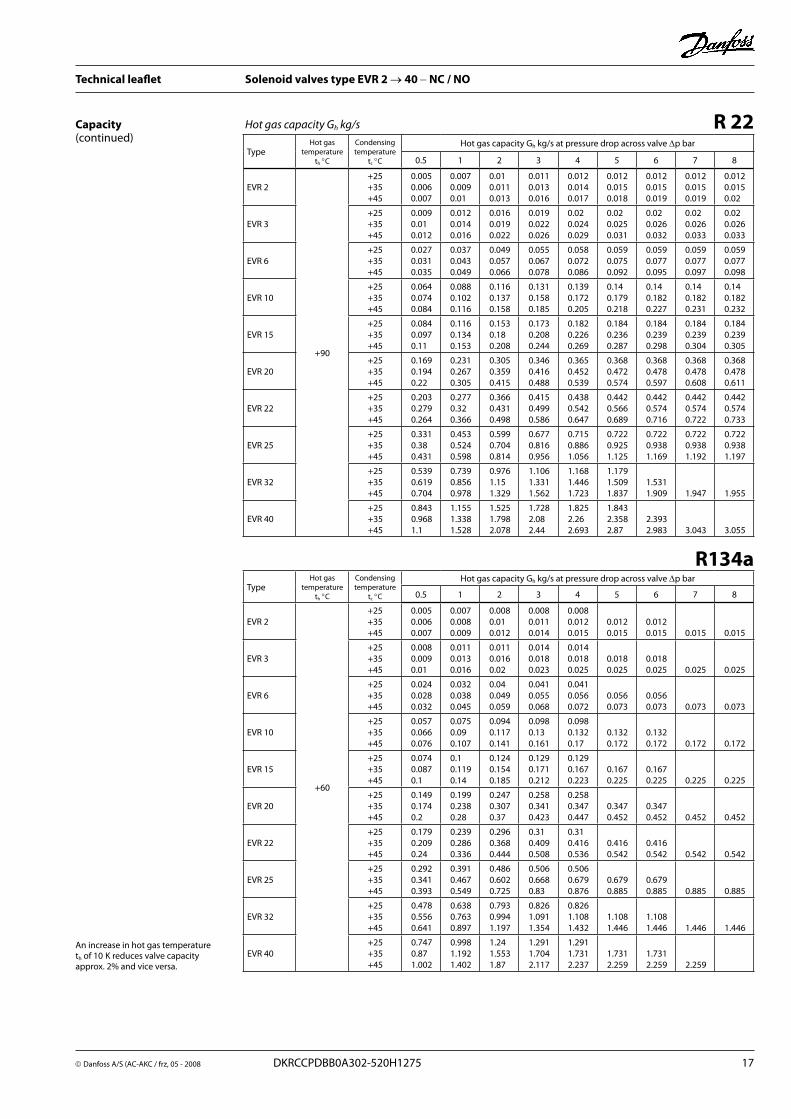
R 22Hot gas capacity Gh kg/sCapacity(continued)
TypeHot gas
temperature th °C
Condensingtemperature
tc °C
Hot gas capacity Gh kg/s at pressure drop across valve ∆p bar
0 .5 1 2 3 4 5 6 7 8
EVR 2
+60
+25+35+45
0 .0050 .0060 .007
0 .0070 .0080 .009
0 .0080 .01 0 .012
0 .0080 .0110 .014
0 .0080 .0120 .015
0 .0120 .015
0 .0120 .015 0 .015 0 .015
EVR 3+25+35+45
0 .0080 .0090 .01
0 .0110 .0130 .016
0 .0110 .0160 .02
0 .0140 .0180 .023
0 .0140 .0180 .025
0 .0180 .025
0 .0180 .025 0 .025 0 .025
EVR 6+25+35+45
0 .0240 .0280 .032
0 .0320 .0380 .045
0 .04 0 .0490 .059
0 .0410 .0550 .068
0 .0410 .0560 .072
0 .0560 .073
0 .0560 .073 0 .073 0 .073
EVR 10+25+35+45
0 .0570 .0660 .076
0 .0750 .09 0 .107
0 .0940 .1170 .141
0 .0980 .13 0 .161
0 .0980 .1320 .17
0 .1320 .172
0 .1320 .172 0 .172 0 .172
EVR 15+25+35+45
0 .0740 .0870 .1
0 .1 0 .1190 .14
0 .1240 .1540 .185
0 .1290 .1710 .212
0 .1290 .1670 .223
0 .1670 .225
0 .1670 .225 0 .225 0 .225
EVR 20+25+35+45
0 .1490 .1740 .2
0 .1990 .2380 .28
0 .2470 .3070 .37
0 .2580 .3410 .423
0 .2580 .3470 .447
0 .3470 .452
0 .3470 .452 0 .452 0 .452
EVR 22+25+35+45
0 .1790 .2090 .24
0 .2390 .2860 .336
0 .2960 .3680 .444
0 .31 0 .4090 .508
0 .31 0 .4160 .536
0 .4160 .542
0 .4160 .542 0 .542 0 .542
EVR 25+25+35+45
0 .2920 .3410 .393
0 .3910 .4670 .549
0 .4860 .6020 .725
0 .5060 .6680 .83
0 .5060 .6790 .876
0 .6790 .885
0 .6790 .885 0 .885 0 .885
EVR 32+25+35+45
0 .4780 .5560 .641
0 .6380 .7630 .897
0 .7930 .9941 .197
0 .8261 .0911 .354
0 .8261 .1081 .432
1 .1081 .446
1 .1081 .446 1 .446 1 .446
EVR 40+25+35+45
0 .7470 .87 1 .002
0 .9981 .1921 .402
1 .24 1 .5531 .87
1 .2911 .7042 .117
1 .2911 .7312 .237
1 .7312 .259
1 .7312 .259 2 .259
R134a
An increase in hot gas temperature th of 10K reduces valve capacity approx . 2% and vice versa .
18 DKRCCPDBB0A302-520H1275 Danfoss A/S (AC-AKS / frz),, 05 - 2008
Technical leaflet Solenoid valves type EVR 2 → 40 − NC / NO
Capacity(continued)
An increase in hot gas temperature th of 10K reduces valve capacity approx . 2% and vice versa .
TypeHot gas
temperature th °C
Condensingtemperature
tc °C
Hot gas capacity Gh kg/s at pressure drop across valve ∆p bar
0 .5 1 2 3 4 5 6 7 8
EVR 2
+60
+25+35+45
0 .0070 .0080 .009
0 .0090 .0110 .012
0 .0120 .0140 .016
0 .0140 .0170 .019
0 .0160 .0190 .021
0 .0160 .02 0 .024
0 .0160 .02 0 .025
0 .0160 .02 0 .025
0 .0160 .02 0 .025
EVR 3+25+35+45
0 .0110 .0130 .015
0 .0160 .0180 .02
0 .0210 .0240 .028
0 .0240 .0290 .032
0 .0260 .0310 .037
0 .0260 .0330 .039
0 .0270 .0350 .041
0 .0270 .0350 .043
0 .0270 .0350 .043
EVR 6+25+35+45
0 .0340 .0380 .043
0 .0470 .0540 .061
0 .0620 .0720 .082
0 .0720 .0850 .097
0 .0770 .0930 .108
0 .0790 .0980 .116
0 .08 0 .1010 .122
0 .08 0 .1010 .126
0 .08 0 .1020 .128
EVR 10+25+35+45
0 .08 0 .0910 .102
0 .11 0 .1270 .143
0 .1480 .1710 .194
0 .17 0 .2 0 .23
0 .1830 .22 0 .257
0 .1880 .2330 .277
0 .19 0 .2410 .288
0 .19 0 .2410 .3
0 .19 0 .2430 .303
EVR 15+25+35+45
0 .1050 .12 0 .135
0 .1460 .1670 .189
0 .1950 .2240 .225
0 .2240 .2530 .303
0 .24 0 .2890 .339
0 .2470 .3070 .365
0 .2490 .3160 .38
0 .2490 .3170 .393
0 .2490 .32 0 .399
EVR 20+25+35+45
0 .21 0 .2390 .27
0 .29 0 .3330 .375
0 .39 0 .45 0 .51
0 .4480 .5260 .606
0 .48 0 .58 0 .677
0 .4950 .6140 .729
0 .5 0 .6320 .76
0 .5 0 .6330 .785
0 .5 0 .6390 .799
EVR 22+25+35+45
0 .2520 .2870 .324
0 .3480 .4 0 .45
0 .4680 .54 0 .612
0 .5380 .6310 .727
0 .5760 .6960 .812
0 .5940 .7370 .875
0 .6 0 .7580 .912
0 .6 0 .76 0 .942
0 .6 0 .7670 .959
EVR 25+25+35+45
0 .4110 .4680 .529
0 .57 0 .6530 .734
0 .7630 .8811 .0
0 .8781 .0321 .188
0 .9421 .1361 .326
0 .9691 .2031 .43
0 .9781 .2391 .49
0 .9781 .2411 .539
0 .9781 .2531 .566
EVR 32+25+35+45
0 .6720 .7650 .862
0 .9311 .0691 .198
1 .2451 .4361 .632
1 .4321 .6861 .939
1 .5391 .8542 .16
1 .5811 .9642 .34
1 .5812 .0222 .433
1 .5812 .0252 .513
1 .5812 .0252 .557
EVR 40+25+35+45
1 .05 1 .1951 .348
1 .4541 .6571 .873
1 .9462 .2452 .55
2 .2382 .6353 .03
2 .4062 .8973 .384
2 .4713 .0683 .65
2 .4713 .1613 .801
2 .4713 .1663 .926
2 .4713 .1663 .995
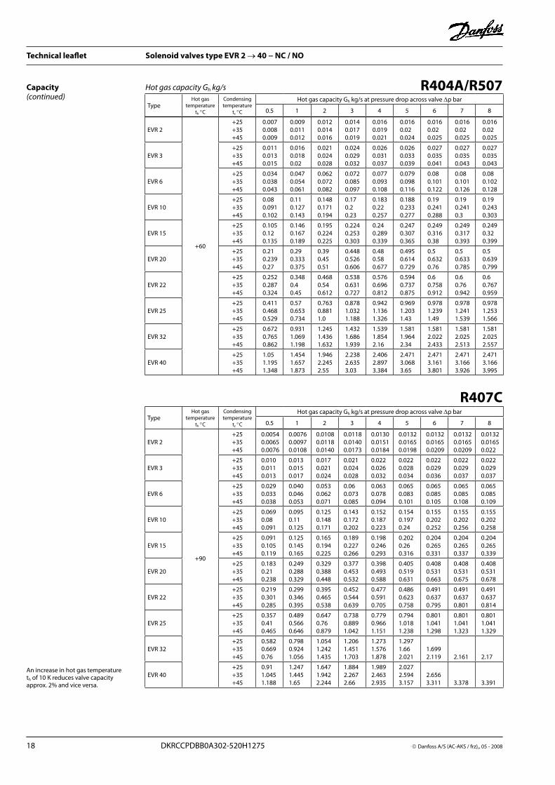
R404A/R507Hot gas capacity Gh kg/s
TypeHot gas
temperature th °C
Condensingtemperature
tc °C
Hot gas capacity Gh kg/s at pressure drop across valve ∆p bar
0 .5 1 2 3 4 5 6 7 8
EVR 2
+90
+25+35+45
0 .00540 .00650 .0076
0 .00760 .00970 .0108
0 .01080 .01180 .0140
0 .01180 .01400 .0173
0 .01300 .01510 .0184
0 .01320 .01650 .0198
0 .01320 .01650 .0209
0 .01320 .01650 .0209
0 .01320 .01650 .022
EVR 3+25+35+45
0 .0100 .0110 .013
0 .0130 .0150 .017
0 .0170 .0210 .024
0 .0210 .0240 .028
0 .0220 .0260 .032
0 .0220 .0280 .034
0 .0220 .0290 .036
0 .0220 .0290 .037
0 .0220 .0290 .037
EVR 6+25+35+45
0 .0290 .0330 .038
0 .0400 .0460 .053
0 .0530 .0620 .071
0 .060 .0730 .085
0 .0630 .0780 .094
0 .0650 .0830 .101
0 .0650 .0850 .105
0 .0650 .0850 .108
0 .0650 .0850 .109
EVR 10+25+35+45
0 .0690 .080 .091
0 .0950 .110 .125
0 .1250 .1480 .171
0 .1430 .1720 .202
0 .1520 .1870 .223
0 .1540 .1970 .24
0 .1550 .2020 .252
0 .1550 .2020 .256
0 .1550 .2020 .258
EVR 15+25+35+45
0 .0910 .1050 .119
0 .1250 .1450 .165
0 .1650 .1940 .225
0 .1890 .2270 .266
0 .1980 .2460 .293
0 .2020 .260 .316
0 .2040 .2650 .331
0 .2040 .2650 .337
0 .2040 .2650 .339
EVR 20+25+35+45
0 .1830 .210 .238
0 .2490 .2880 .329
0 .3290 .3880 .448
0 .3770 .4530 .532
0 .3980 .4930 .588
0 .4050 .5190 .631
0 .4080 .5310 .663
0 .4080 .5310 .675
0 .4080 .5310 .678
EVR 22+25+35+45
0 .2190 .3010 .285
0 .2990 .3460 .395
0 .3950 .4650 .538
0 .4520 .5440 .639
0 .4770 .5910 .705
0 .4860 .6230 .758
0 .4910 .6370 .795
0 .4910 .6370 .801
0 .4910 .6370 .814
EVR 25+25+35+45
0 .3570 .410 .465
0 .4890 .5660 .646
0 .6470 .760 .879
0 .7380 .8891 .042
0 .7790 .9661 .151
0 .7941 .0181 .238
0 .8011 .0411 .298
0 .8011 .0411 .323
0 .8011 .0411 .329
EVR 32+25+35+45
0 .5820 .6690 .76
0 .7980 .9241 .056
1 .0541 .2421 .435
1 .2061 .4511 .703
1 .2731 .5761 .878
1 .2971 .662 .021
1 .6992 .119 2 .161 2 .17
EVR 40+25+35+45
0 .911 .0451 .188
1 .2471 .4451 .65
1 .6471 .9422 .244
1 .8842 .2672 .66
1 .9892 .4632 .935
2 .0272 .5943 .157
2 .6563 .311 3 .378 3 .391
R407C
Danfoss A/S (AC-AKC / frz, 05 - 2008 DKRCCPDBB0A302-520H1275 19
Technical leaflet Solenoid valves type EVR 2 → 40 − NC / NO
Design / Function
EVR 2 (NC)
EVR 10 (NC)EVR 10 (NO)
EVR 32 and 40 (NC)EVR 25 (NC)
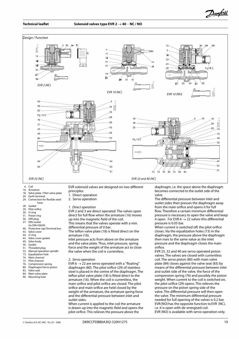
4 . Coil16 . Armature18 . Valve plate / Pilot valve plate20 . Earth terminal24 . Connection for flexible steel
hose28 . Gasket29 . Pilot orifice30 . O-ring31 . Piston ring36 . DIN plug37 . DIN socket (to DIN 43650) 40 . Protective cap/Terminal box43 . Valve cover44 . O-ring45 . Valve cover gasket49 . Valve body50 . Gasket51 . Threaded plug53 . Manual operation spindle73 . Equalization hole74 . Main channel75 . Pilot channel76 . Compression spring80 . Diaphragm/Servo piston83 . Valve seat84 . Main valve plate90 . Mounting hole
EVR solenoid valves are designed on two different principles:1 . Direct operation2 . Servo operation
1. Direct operationEVR 2 and 3 are direct operated . The valves open direct for full flow when the armature (16) moves up into the magnetic field of the coil . This means that the valves operate with a min . differential pressure of 0 bar .The teflon valve plate (18) is fitted direct on the armature (16) . Inlet pressure acts from above on the armature and the valve plate . Thus, inlet pressure, spring force and the weight of the armature act to close the valve when the coil is currentless .
2. Servo operationEVR 6 → 22 are servo operated with a "floating" diaphragm (80) . The pilot orifice (29) of stainless steel is placed in the centre of the diaphragm . The teflon pilot valve plate (18) is fitted direct to the armature (16) . When the coil is currentless, the main orifice and pilot orifice are closed . The pilot orifice and main orifice are held closed by the weight of the armature, the armature spring force and the differential pressure between inlet and outlet sides .When current is applied to the coil the armature is drawn up into the magnetic field and opens the pilot orifice . This relieves the pressure above the
diaphragm, i .e . the space above the diaphragm becomes connected to the outlet side of the valve . The differential pressure between inlet and outlet sides then presses the diaphragm away from the main orifice and opens it for full flow . Therefore a certain minimum differential pressure is necessary to open the valve and keep it open . For EVR 6 → 22 valves this differential pressure is 0 .05 bar .When current is switched off, the pilot orifice closes . Via the equalization holes (73) in the diaphragm, the pressure above the diaphragm then rises to the same value as the inlet pressure and the diaphragm closes the main orifice .EVR 25, 32 and 40 are servo operated piston valves . The valves are closed with currentless coil . The servo piston (80) with main valve plate (84) closes against the valve seat (83) by means of the differential pressure between inlet and outlet side of the valve, the force of the compression spring (76) and possibly the piston weight . When current to the coil is switched on, the pilot orifice (29) opens . This relieves the pressure on the piston spring side of the valve . The differential pressure will then open the valve . The minimum differential pressure needed for full opening of the valves is 0 .2 bar . EVR (NO) has the opposite function to EVR (NC), i .e . it is open with de-energised coil . EVR (NO) is available with servo operation only .

20 DKRCCPDBB0A302-520H1275 Danfoss A/S (AC-AKS / frz),, 05 - 2008
Technical leaflet Solenoid valves type EVR 2 → 40 − NC / NO
Material specificationsEVR 2 to 25
Solenoid valves Standard
No . Description Type Material Analysis Mat .no . W .no . DIN EN
1 Valve body EVR 2 to 25 Brass CuZn40Pb2 CW617N 2 .0402 17672-1 12165
2 Cover
EVR 2 to 3 Stainless steel X5 CrNi18-10 1 .4301 10088
EVR 6 to 22 Brass CuZn40Pb2 CW617N 2 .0402 17672-1 12165
EVR 25 Cast iron EN-GJS-400-18-LT EN-JS1025 1563
3 Armature tube EVR 2 to 25 Stainless steel X2 CrNi19-11 1 .4306 10088
4 Armature tube nut EVR 25 Stainless steel X8 CrNiS 18-9 1 .4305 10088
5 Gasket EVR 2 to 25 Rubber Cr
6 Gasket EVR 25 Al . gasket Al 99 .5 3 .0255 10210
7 Solder tube EVR 25 Copper SF-Cu CW024A 2 .0090 1787 12449
8 Screws EVR 2 to 25 Stainless steel A2-70 3506
9 Spindle for man . operat . EVR 25 Stainless steel X8 CrNiS 18-9 1 .4305 10088
10 Gasket EVR 25 Rubber Cr
Solenoid valves Standard
No . Description Type Material Analysis Mat .no . W .no . DIN EN
1 Valve body EVR 32/40 Cast Iron EN-GJS-400-18-LT EN-JS1025 1563
2 Cover EVR 32/40 Brass CuZn40Pb2 CW617N 2 .0402 12165
3 Armature tube EVR 32/40 Stainless steel X2 CrNi19-11 1 .4306 10088
4 Armature tube nut EVR 32/40 Stainless steel X8 CrNiS 18-9 1 .4305 10088
5 Gasket EVR 32/40 Rubber Cr
6 Gasket EVR 32/40 Al . gasket Al 99 .5 3 .0255 10210
7 Solder tube EVR 32/40 Copper SF .Cu CW024A 2 .0090 1787 12449
8 Screws EVR 32/40 Stainless steel A2-70 3506
9 Spindle for . man . operation EVR 32/40 Stainless steel X8 CrNiS 18-9 1 .4305 10088
EVR 32 to 40

Danfoss A/S (AC-AKC / frz, 05 - 2008 DKRCCPDBB0A302-520H1275 21
Technical leaflet Solenoid valves type EVR 2 → 40 − NC / NO
Dimensions andweights
EVR (NC) 2→ 15 and EVR 6 → 15 (NO) , flare connection
With DIN plugs coilWith cable connection coil
Weight of coil10 W: approx . 0 .3 kg
12 and 20 W: approx . 0 .5 kg
With terminal box coil
TypeConnection
FlareH1 H2 H3 H4 L L2 L3 L4
NV L5 max .B B1 max .
Weight with coil10 W 12/20 W
in . mm mm mm mm mm mm mm mm mm mm mm mm mm mm kg
EVR 2 1/4 6 14 73 9 75 45 54 13 75 85 33 68 0 .5
EVR 31/4 6 14 73 9 75 45 54 13 75 85 33 68 0 .53/8 10 14 73 9 75 45 54 13 75 85 33 68 0 .5
EVR 63/8 10 14 78 10 82 45 54 14 75 85 36 68 0 .61/2 12 14 78 10 88 45 54 14 75 85 36 68 0 .6
EVR 101/2 12 16 79 11 103 45 54 16 75 85 46 68 0 .85/8 16 16 79 11 110 45 54 16 75 85 46 68 0 .8
EVR 15 5/8 16 19 86 49 131 45 54 24 75 85 56 68 1 .0

22 DKRCCPDBB0A302-520H1275 Danfoss A/S (AC-AKS / frz),, 05 - 2008
Technical leaflet Solenoid valves type EVR 2 → 40 − NC / NO
Dimensions and weights(continued)
EVR (NC) 2 →22 and EVR 6 → 22 (NO), solder connection
With cable connection coil
With terminal box coil
TypeConnection
SolderH1 H2 H3 H4 L L2 L3 L4
L5 max .B B1 max .
Weightwith coil
10 W 12/20 W
in . mm mm mm mm mm mm mm mm mm mm mm mm mm kg
EVR 2 1/4 6 14 73 9 102 7 45 54 75 85 33 68 0 .5
EVR 31/4 6 14 73 9 102 7 45 54 75 85 33 68 0 .63/8 10 14 73 9 117 9 45 54 75 85 33 68 0 .6
EVR 63/8 10 14 78 10 111 9 45 54 75 85 36 68 0 .61/2 12 14 78 10 127 10 45 54 75 85 36 68 0 .6
EVR 101/2 12 16 79 11 127 10 45 54 75 85 46 68 0 .75/8 16 16 79 11 160 12 45 54 75 85 46 68 0 .7
EVR 155/8 16 19 86 49 176 12 45 54 75 85 56 68 1 .07/8 22 19 86 176 17 45 54 75 85 56 68 1 .0
EVR 207/8 22 20 90 53 191 17 45 54 75 85 72 68 1 .5
11/8 28 20 90 214 22 45 54 75 85 72 68 1 .5
EVR 22 13/8 35 20 90 281 25 45 54 75 85 72 68 1 .5
With DIN plugs coil
Weight of coil10 W: approx . 0 .3 kg
12 and 20 W: approx . 0 .5 kg

Danfoss A/S (AC-AKC / frz, 05 - 2008 DKRCCPDBB0A302-520H1275 23
Technical leaflet Solenoid valves type EVR 2 → 40 − NC / NO
Dimensions and weights (continued)
EVR (NC) 25, 32 og 40, solder connection
EVR 25 with terminal box coil
EVR 32 and 40 terminal box
Weight of coil10 W: approx . 0 .3 kg12 and 20 W: approx . 0 .5 kg
EVR 25
EVR 32 and 40
Coil with cable
TypeConnection
SolderH1 H2 H3 H4 L L2
Coil withcable
connectionL3
Coil withDIN
connectionL4
Coil withterminal box
L5 max . B B1 max .Weight
with coil
10 W 12/20 W
in . mm mm mm mm mm mm mm mm mm mm mm mm mm kg
EVR 2511/8 28 38 138 72 256 22 45 54 75 85 95 68 3 .0
13/8 35 38 138 72 281 25 45 54 75 85 95 68 3 .3
EVR 3213/8 35 47 111 53 281 25 45 54 75 85 80 68 4 .5
15/8 42 47 111 53 281 29 45 54 75 85 80 68 4 .6
EVR 4015/8 42 47 111 53 281 29 45 54 75 85 80 68 4 .6
21/8 54 47 111 53 281 34 45 54 75 85 80 68 4 .6
EVR (NC) 15 and 20, flange connection
With terminal box coil
Type H1 H2 H3 H4 L L1 L2
Coil with cable connection
L3
Coil with DINconnection
L4
Coil withterminal box
L5 max . B B1 max .
Weightwith coil
excl . flanges10 W 12/20 W
mm mm mm mm mm mm mm mm mm mm mm mm mm kg
EVR 15 19 86 19 49 125 68 45 54 75 85 80 68 1 .2
EVR 20 20 90 21 53 155 85 45 54 75 85 96 68 1 .7
Coil with cable Coil with DIN plugs
Weight of coil10 W: approx . 0 .3 kg
12 and 20 W: approx . 0 .5 kg
Weight of flange setFor EVR 15: 0 .6 kgFor EVR 20: 0 .9 kg
Coil with DIN plugs
24 DKRCCPDBB0A302-520H1275 Danfoss A/S (AC-AKS / frz),, 05 - 2008
Technical leaflet Solenoid valves type EVR 2 → 40 − NC / NO
Related Documents