HITACHI INVERTER SJ700B SERIES INSTRUCTION MANUAL Read through this Instruction Manual, and keep it handy for future reference. NT907DX

Welcome message from author
This document is posted to help you gain knowledge. Please leave a comment to let me know what you think about it! Share it to your friends and learn new things together.
Transcript
HITACHI INVERTER
SJ700B SERIES
INSTRUCTION MANUAL
Read through this Instruction Manual, and keep it handy for future reference.NT907DX
DAVID
Typewritten Text
DAVID
Typewritten Text
CALL NOW 800-985-6929 AutomatedPT.com
DAVID
Typewritten Text
DAVID
Typewritten Text
Introduction Thank you for purchasing the Hitachi SJ700B Series Inverter. This Instruction Manual describes how to handle and maintain the Hitachi SJ700B Series Inverter. Read this Instruction Manual carefully before using the inverter, and then keep it handy for those who operate, maintain, and inspect the inverter. Before and during the installation, operation, inspection, and maintenance of the inverter, always refer to this Instruction Manual to obtain the necessary related knowledge, and ensure you understand and follow all safety information, precautions, and operating and handling instructions for the correct use of the inverter. Always use the inverter strictly within the range of the specifications described in this Instruction Manual and correctly implement maintenance and inspections to prevent faults occurring. When using the inverter together with optional products, also read the manuals for those products. Note that this Instruction Manual and the manual for each optional product to be used should be delivered to the end user of the inverter. Handling of this Instruction Manual - The contents of this Instruction Manual are subject to change without prior notice. - Even if you lose this Instruction Manual, it will not be resupplied, so please keep it carefully. - No part of this Instruction Manual may be reproduced in any form without the publisher’s permission. - If you find any incorrect description, missing description or have a question concerning the contents of
this Instruction Manual, please contact the publisher.
Revision History
No. Revision content Date of issue Manual code 1 First edition Jul. 2011 NT907AX
2 The starting torque was modified and some notes was add or modified Feb.2012 NT907BX
3 The specification of the capacity 5.5-7.5kW,HAL model,200V class model and more was added Feb.2013 NT907DX
- The current edition of this Instruction Manual also includes some corrections of simple misprints,
missing letters, misdescriptions and certain added explanations other than those listed in the above Revision History table.
Contents
i
Safety Instructions Be sure to read this Instruction Manual and appended documents thoroughly before installing, operating, maintaining, or inspecting the inverter. In this Instruction Manual, safety instructions are classified into two levels, namely WARNING and CAUTION.
: Indicates that incorrect handling may cause hazardous situations, which may result in serious personal injury or death.
: Indicates that incorrect handling may cause hazardous situations, which may result in
moderate or slight personal injury or physical damage alone. Note that even a level situation may lead to a serious consequence according to circumstances. Be sure to follow every safety instruction, which contains important safety information. Also focus on and observe the items and instructions described under "Notes" in the text.
CAUTION
Many of the drawings in this Instruction Manual show the inverter with covers and/or parts blocking your view being removed. Do not operate the inverter in the status shown in those drawings. If you have removed the covers and/or parts, be sure to reinstall them in their original positions before starting operation, and follow all instructions in this Instruction Manual when operating the inverter.
1. Installation
CAUTION
- Install the inverter on a non-flammable surface, e.g., metal. Otherwise, you run the risk of fire. - Do not place flammable materials near the installed inverter. Otherwise, you run the risk of fire. - When carrying the inverter, do not hold its top cover. Otherwise, you run the risk of injury by dropping
the inverter. - Prevent foreign matter (e.g., cut pieces of wire, sputtering welding materials, iron chips, wire, and
dust) from entering the inverter. Otherwise, you run the risk of fire. - Install the inverter on a structure able to bear the weight specified in this Instruction Manual.
Otherwise, you run the risk of injury due to the inverter falling. - Install the inverter on a vertical wall that is free of vibrations. Otherwise, you run the risk of injury due
to the inverter falling. - Do not install and operate the inverter if it is damaged or its parts are missing. Otherwise, you run the
risk of injury. - Install the inverter in a well-ventilated indoor site not exposed to direct sunlight. Avoid places where
the inverter is exposed to high temperature, high humidity, condensation, dust, explosive gases, corrosive gases, flammable gases, grinding fluid mist, or salt water. Otherwise, you run the risk of fire.
- The inverter is precision equipment. Do not allow it to fall or be subject to high impacts, step on it, or place a heavy load on it. Doing so may cause the inverter to fail.
! WARNING
! CAUTION
!
!
! CAUTION
Contents
ii
2. Wiring
WARNING
- Be sure to ground the inverter. Otherwise, you run the risk of electric shock or fire. - Commit wiring work to a qualified electrician. Otherwise, you run the risk of electric shock or fire. - Before wiring, make sure that the power supply is off. Otherwise, you run the risk of electric shock or
fire. - Perform wiring only after installing the inverter. Otherwise, you run the risk of electric shock or injury. - Do not remove rubber bushings from the wiring section. Otherwise, the edges of the wiring cover may
damage the wire, resulting in a short circuit or ground fault.
CAUTION
- Make sure that the voltage of AC power supply matches the rated voltage of your inverter. Otherwise, you run the risk of injury or fire.
- Do not input single-phase power into the inverter. Otherwise, you run the risk of fire. - Do not connect AC power supply to any of the output terminals (U, V, and W). Otherwise, you run the
risk of injury or fire. - Do not connect a resistor directly to any of the DC terminals (PD, P, and N). Otherwise, you run the
risk of fire. - Connect an earth-leakage breaker to the power input circuit. Otherwise, you run the risk of fire. - Use only the power cables, earth-leakage breaker, and magnetic contactors that have the specified
capacity (ratings). Otherwise, you run the risk of fire. - Do not use the magnetic contactor installed on the primary and secondary sides of the inverter to stop
its operation. - Tighten each screw to the specified torque. No screws must be left loose. Otherwise, you run the risk
of fire. - Before operating, slide switch SW1 in the inverter, be sure to turn off the power supply. Otherwise, you
run the risk of electric shock and injury. - Since the inverter supports two modes of cooling-fan operation, the inverter power is not always off,
even when the cooling fan is stopped. Therefore, be sure to confirm that the power supply is off before wiring. Otherwise, you run the risk of electric shock and injury.
!
!
Contents
iii
3. Operation
WARNING
- While power is supplied to the inverter, do not touch any terminal or internal part of the inverter, check signals, or connect or disconnect any wire or connector. Otherwise, you run the risk of electric shock or fire.
- Be sure to close the terminal block cover before turning on the inverter power. Do not open the terminal block cover while power is being supplied to the inverter or voltage remains inside. Otherwise, you run the risk of electric shock.
- Do not operate switches with wet hands. Otherwise, you run the risk of electric shock. - While power is supplied to the inverter, do not touch the terminal of the inverter, even if it has stopped.
Otherwise, you run the risk of injury or fire. - If the retry mode has been selected, the inverter will restart suddenly after a break in the tripping
status. Stay away from the machine controlled by the inverter when the inverter is under such circumstances. (Design the machine so that human safety can be ensured, even when the inverter restarts suddenly.) Otherwise, you run the risk of injury.
- Do not select the retry mode for controlling an elevating or traveling device because output free-running status occurs in retry mode. Otherwise, you run the risk of injury or damage to the machine controlled by the inverter.
- If an operation command has been input to the inverter before a short-term power failure, the inverter may restart operation after the power recovery. If such a restart may put persons in danger, design a control circuit that disables the inverter from restarting after power recovery. Otherwise, you run the risk of injury.
- The [STOP] key is effective only when its function is enabled by setting. Prepare an emergency stop switch separately. Otherwise, you run the risk of injury.
- If an operation command has been input to the inverter before the inverter enters alarm status, the inverter will restart suddenly when the alarm status is reset. Before resetting the alarm status, make sure that no operation command has been input.
- While power is supplied to the inverter, do not touch any internal part of the inverter or insert a bar in it. Otherwise, you run the risk of electric shock or fire.
CAUTION
- Do not touch the heat sink, which heats up during the inverter operation. Otherwise, you run the risk of burn injury.
- The inverter allows you to easily control the speed of motor or machine operations. Before operating the inverter, confirm the capacity and ratings of the motor or machine controlled by the inverter. Otherwise, you run the risk of injury.
- Install an external brake system if needed. Otherwise, you run the risk of injury. - When using the inverter to operate a standard motor at a frequency of over 60 Hz, check the allowable
motor speeds with the manufacturers of the motor and the machine to be driven and obtain their consent before starting inverter operation. Otherwise, you run the risk of damage to the motor and machine.
- During inverter operation, check the motor for the direction of rotation, abnormal sound, and vibrations. Otherwise, you run the risk of damage to the machine driven by the motor.
!
!
Contents
iv
4. Maintenance, inspection, and parts replacement
WARNING
- Before inspecting the inverter, be sure to turn off the power supply and wait for 10 minutes or more. Otherwise, you run the risk of electric shock. (Before inspection, confirm that the Charge lamp on the inverter is off and the DC voltage between terminals P and N is 45V or less.)
- Commit only a designated person to maintenance, inspection, and the replacement of parts. (Be sure to remove wristwatches and metal accessories, e.g., bracelets, before maintenance and inspection work and to use insulated tools for the work.) Otherwise, you run the risk of electric shock and injury.
5. Others
WARNING
- Never modify the inverter. Otherwise, you run the risk of electric shock and injury.
CAUTION
- Do not discard the inverter with household waste. Contact an industrial waste management company in your area who can treat industrial waste without polluting the environment.
!
!
!
Contents
v
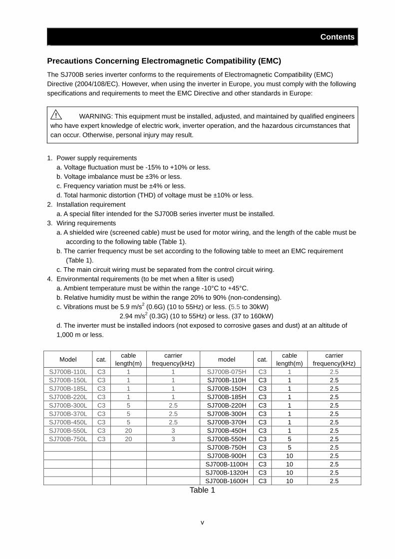
Precautions Concerning Electromagnetic Compatibility (EMC) The SJ700B series inverter conforms to the requirements of Electromagnetic Compatibility (EMC) Directive (2004/108/EC). However, when using the inverter in Europe, you must comply with the following specifications and requirements to meet the EMC Directive and other standards in Europe:
WARNING: This equipment must be installed, adjusted, and maintained by qualified engineers who have expert knowledge of electric work, inverter operation, and the hazardous circumstances that can occur. Otherwise, personal injury may result.
1. Power supply requirements
a. Voltage fluctuation must be -15% to +10% or less. b. Voltage imbalance must be ±3% or less. c. Frequency variation must be ±4% or less. d. Total harmonic distortion (THD) of voltage must be ±10% or less.
2. Installation requirement a. A special filter intended for the SJ700B series inverter must be installed.
3. Wiring requirements a. A shielded wire (screened cable) must be used for motor wiring, and the length of the cable must be
according to the following table (Table 1). b. The carrier frequency must be set according to the following table to meet an EMC requirement
(Table 1). c. The main circuit wiring must be separated from the control circuit wiring.
4. Environmental requirements (to be met when a filter is used) a. Ambient temperature must be within the range -10°C to +45°C. b. Relative humidity must be within the range 20% to 90% (non-condensing). c. Vibrations must be 5.9 m/s2 (0.6G) (10 to 55Hz) or less. (5.5 to 30kW) 2.94 m/s2 (0.3G) (10 to 55Hz) or less. (37 to 160kW) d. The inverter must be installed indoors (not exposed to corrosive gases and dust) at an altitude of 1,000 m or less.
Table 1
Model cat. cable length(m)
carrier frequency(kHz) model cat. cable
length(m) carrier
frequency(kHz)SJ700B-110L C3 1 1 SJ700B-075H C3 1 2.5 SJ700B-150L C3 1 1 SJ700B-110H C3 1 2.5 SJ700B-185L C3 1 1 SJ700B-150H C3 1 2.5 SJ700B-220L C3 1 1 SJ700B-185H C3 1 2.5 SJ700B-300L C3 5 2.5 SJ700B-220H C3 1 2.5 SJ700B-370L C3 5 2.5 SJ700B-300H C3 1 2.5 SJ700B-450L C3 5 2.5 SJ700B-370H C3 1 2.5 SJ700B-550L C3 20 3 SJ700B-450H C3 1 2.5 SJ700B-750L C3 20 3 SJ700B-550H C3 5 2.5
SJ700B-750H C3 5 2.5 SJ700B-900H C3 10 2.5 SJ700B-1100H C3 10 2.5 SJ700B-1320H C3 10 2.5 SJ700B-1600H C3 10 2.5
!
Contents
vi
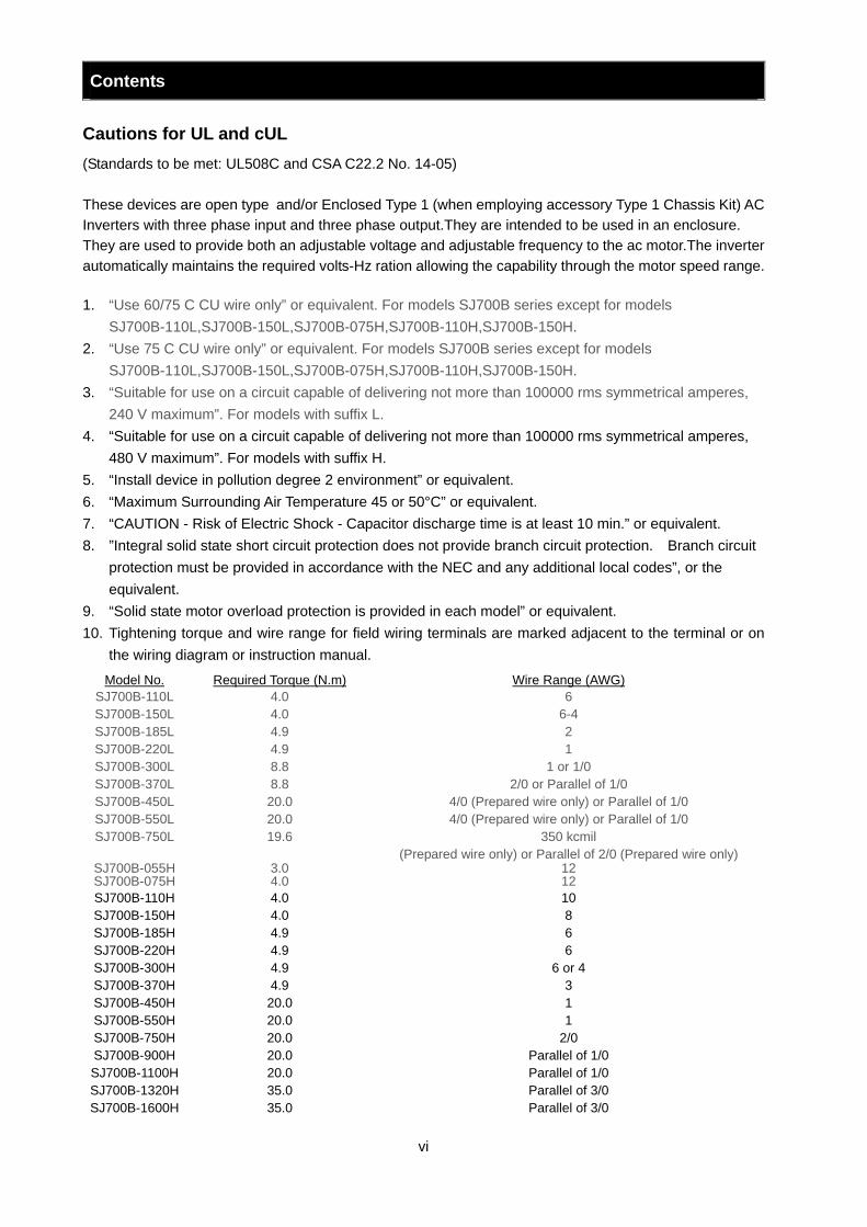
Cautions for UL and cUL (Standards to be met: UL508C and CSA C22.2 No. 14-05) These devices are open type and/or Enclosed Type 1 (when employing accessory Type 1 Chassis Kit) AC Inverters with three phase input and three phase output.They are intended to be used in an enclosure. They are used to provide both an adjustable voltage and adjustable frequency to the ac motor.The inverter automatically maintains the required volts-Hz ration allowing the capability through the motor speed range. 1. “Use 60/75 C CU wire only” or equivalent. For models SJ700B series except for models
SJ700B-110L,SJ700B-150L,SJ700B-075H,SJ700B-110H,SJ700B-150H. 2. “Use 75 C CU wire only” or equivalent. For models SJ700B series except for models
SJ700B-110L,SJ700B-150L,SJ700B-075H,SJ700B-110H,SJ700B-150H. 3. “Suitable for use on a circuit capable of delivering not more than 100000 rms symmetrical amperes,
240 V maximum”. For models with suffix L. 4. “Suitable for use on a circuit capable of delivering not more than 100000 rms symmetrical amperes,
480 V maximum”. For models with suffix H. 5. “Install device in pollution degree 2 environment” or equivalent. 6. “Maximum Surrounding Air Temperature 45 or 50°C” or equivalent. 7. “CAUTION - Risk of Electric Shock - Capacitor discharge time is at least 10 min.” or equivalent. 8. ”Integral solid state short circuit protection does not provide branch circuit protection. Branch circuit
protection must be provided in accordance with the NEC and any additional local codes”, or the equivalent.
9. “Solid state motor overload protection is provided in each model” or equivalent. 10. Tightening torque and wire range for field wiring terminals are marked adjacent to the terminal or on
the wiring diagram or instruction manual.
Model No. Required Torque (N.m) Wire Range (AWG) SJ700B-110L 4.0 6 SJ700B-150L 4.0 6-4 SJ700B-185L 4.9 2 SJ700B-220L 4.9 1 SJ700B-300L 8.8 1 or 1/0 SJ700B-370L 8.8 2/0 or Parallel of 1/0 SJ700B-450L 20.0 4/0 (Prepared wire only) or Parallel of 1/0 SJ700B-550L 20.0 4/0 (Prepared wire only) or Parallel of 1/0 SJ700B-750L 19.6 350 kcmil
(Prepared wire only) or Parallel of 2/0 (Prepared wire only) SJ700B-055H 3.0 12 SJ700B-075H 4.0 12 SJ700B-110H 4.0 10 SJ700B-150H 4.0 8 SJ700B-185H 4.9 6 SJ700B-220H 4.9 6 SJ700B-300H 4.9 6 or 4 SJ700B-370H 4.9 3 SJ700B-450H 20.0 1 SJ700B-550H 20.0 1 SJ700B-750H 20.0 2/0 SJ700B-900H 20.0 Parallel of 1/0 SJ700B-1100H 20.0 Parallel of 1/0 SJ700B-1320H 35.0 Parallel of 3/0 SJ700B-1600H 35.0 Parallel of 3/0
Contents
vii
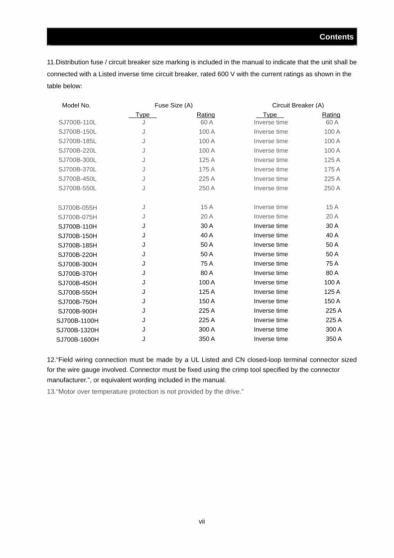
11.Distribution fuse / circuit breaker size marking is included in the manual to indicate that the unit shall be
connected with a Listed inverse time circuit breaker, rated 600 V with the current ratings as shown in the
table below:
12.“Field wiring connection must be made by a UL Listed and CN closed-loop terminal connector sized for the wire gauge involved. Connector must be fixed using the crimp tool specified by the connector manufacturer.”, or equivalent wording included in the manual.
13.“Motor over temperature protection is not provided by the drive.”
Model No. Fuse Size (A) Circuit Breaker (A) Type Rating Type Rating
SJ700B-110L J 60 A Inverse time 60 A SJ700B-150L J 100 A Inverse time 100 A SJ700B-185L J 100 A Inverse time 100 A SJ700B-220L J 100 A Inverse time 100 A SJ700B-300L J 125 A Inverse time 125 A SJ700B-370L J 175 A Inverse time 175 A SJ700B-450L J 225 A Inverse time 225 A SJ700B-550L J 250 A Inverse time 250 A
SJ700B-055H J 15 A Inverse time 15 A SJ700B-075H J 20 A Inverse time 20 A SJ700B-110H J 30 A Inverse time 30 A SJ700B-150H J 40 A Inverse time 40 A SJ700B-185H J 50 A Inverse time 50 A SJ700B-220H J 50 A Inverse time 50 A SJ700B-300H J 75 A Inverse time 75 A SJ700B-370H J 80 A Inverse time 80 A SJ700B-450H J 100 A Inverse time 100 A SJ700B-550H J 125 A Inverse time 125 A SJ700B-750H J 150 A Inverse time 150 A SJ700B-900H J 225 A Inverse time 225 A SJ700B-1100H J 225 A Inverse time 225 A SJ700B-1320H J 300 A Inverse time 300 A SJ700B-1600H J 350 A Inverse time 350 A
Contents
viii
Chapter 1 Overview 1.1 Inspection of the Purchased Product························································································1 - 1
1.1.1 Inspecting the product··································································································1 - 1 1.1.2 Instruction manual (this manual)··················································································1 - 1
1.2 Method of Inquiry and Product Warranty ··················································································1 - 2 1.2.1 Method of inquiry ·········································································································1 - 2 1.2.2 Product warranty··········································································································1 - 2 1.2.3 Warranty Terms············································································································1 - 2
1.3 Exterior Views and Names of Parts ··························································································1 - 3
Chapter 2 Installation and Wiring 2.1 Installation·································································································································2 - 1
2.1.1 Precautions for installation···························································································2 - 2 2.1.2 Backing plate ···············································································································2 - 4
2.2 Wiring········································································································································2 - 5 2.2.1 Terminal connection diagram and explanation of terminals and switch settings·········2 - 6 2.2.2 Wiring of the main circuit ·····························································································2 - 11 2.2.3 Wiring of the control circuit ··························································································2 - 19 2.2.4 Wiring of the digital operator ························································································2 - 20 2.2.5 Selection and wiring of regenerative braking resistor (on 5.5 kW to 30 kW models) ··2 - 21
Chapter 3 Operation 3.1 Operating Methods ···················································································································3 - 1 3.2 How To Operate the Digital Operator························································································3 - 3
3.2.1 Names and functions of components ··········································································3 - 3 3.2.2 Code display system and key operations ····································································3 - 4
3.3 How To Make a Test Run ··········································································································3 - 10
Chapter 4 Explanation of Functions 4.1 Monitor Mode ····························································································································4 - 1
4.1.1 Output frequency monitoring (d001) ············································································4 - 1 4.1.2 Output current monitoring (d002)·················································································4 - 1 4.1.3 Rotation direction minitoring (d003)·············································································4 - 1 4.1.4 Process variable (PV), PID feedback monitoring (d004, A071, A075) ························4 - 1 4.1.5 Intelligent input terminal status (d005)·········································································4 - 2 4.1.6 Intelligent output terminal status (d006)·······································································4 - 2 4.1.7 Scaled output frequency monitoring (d007, b086)·······················································4 - 2 4.1.8 Actual-frequency monitoring (d008, P011, H004, H204) ·············································4 - 3 4.1.9 Torque command monitoring (d009, P033, P034)·······················································4 - 3 4.1.10 Torque bias monitoring (d010, P036 to P038) ·····························································4 - 3 4.1.11 Torque monitoring (d012)·····························································································4 - 3 4.1.12 Output voltage monitoring (d013) ················································································4 - 3 4.1.13 Power monitoring (d014) ·····························································································4 - 3
Contents
ix
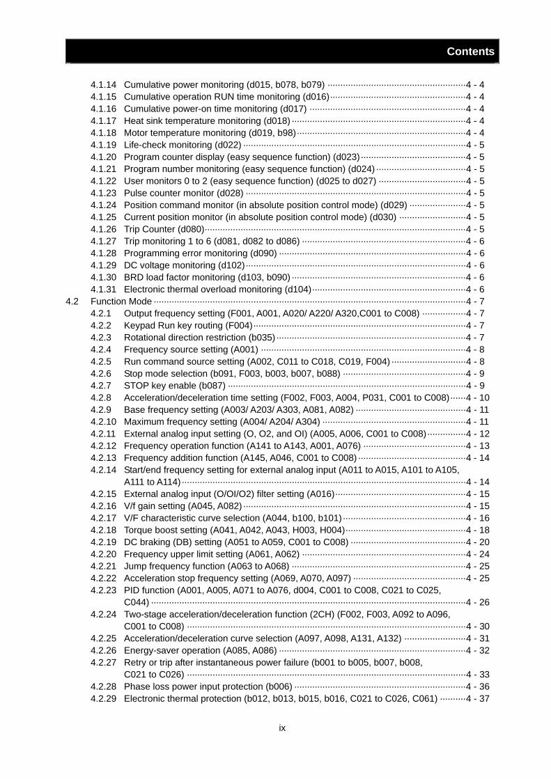
4.1.14 Cumulative power monitoring (d015, b078, b079) ······················································4 - 4 4.1.15 Cumulative operation RUN time monitoring (d016)·····················································4 - 4 4.1.16 Cumulative power-on time monitoring (d017) ·····························································4 - 4 4.1.17 Heat sink temperature monitoring (d018) ····································································4 - 4 4.1.18 Motor temperature monitoring (d019, b98)··································································4 - 4 4.1.19 Life-check monitoring (d022) ·······················································································4 - 5 4.1.20 Program counter display (easy sequence function) (d023)·········································4 - 5 4.1.21 Program number monitoring (easy sequence function) (d024) ···································4 - 5 4.1.22 User monitors 0 to 2 (easy sequence function) (d025 to d027) ··································4 - 5 4.1.23 Pulse counter monitor (d028) ······················································································4 - 5 4.1.24 Position command monitor (in absolute position control mode) (d029) ······················4 - 5 4.1.25 Current position monitor (in absolute position control mode) (d030) ··························4 - 5 4.1.26 Trip Counter (d080)······································································································4 - 5 4.1.27 Trip monitoring 1 to 6 (d081, d082 to d086) ································································4 - 6 4.1.28 Programming error monitoring (d090) ·········································································4 - 6 4.1.29 DC voltage monitoring (d102)······················································································4 - 6 4.1.30 BRD load factor monitoring (d103, b090) ····································································4 - 6 4.1.31 Electronic thermal overload monitoring (d104)····························································4 - 6
4.2 Function Mode ··························································································································4 - 7 4.2.1 Output frequency setting (F001, A001, A020/ A220/ A320,C001 to C008) ·················4 - 7 4.2.2 Keypad Run key routing (F004)···················································································4 - 7 4.2.3 Rotational direction restriction (b035)··········································································4 - 7 4.2.4 Frequency source setting (A001) ················································································4 - 8 4.2.5 Run command source setting (A002, C011 to C018, C019, F004) ·····························4 - 8 4.2.6 Stop mode selection (b091, F003, b003, b007, b088) ················································4 - 9 4.2.7 STOP key enable (b087) ·····························································································4 - 9 4.2.8 Acceleration/deceleration time setting (F002, F003, A004, P031, C001 to C008)······4 - 10 4.2.9 Base frequency setting (A003/ A203/ A303, A081, A082) ···········································4 - 11 4.2.10 Maximum frequency setting (A004/ A204/ A304) ························································4 - 11 4.2.11 External analog input setting (O, O2, and OI) (A005, A006, C001 to C008)···············4 - 12 4.2.12 Frequency operation function (A141 to A143, A001, A076) ········································4 - 13 4.2.13 Frequency addition function (A145, A046, C001 to C008) ··········································4 - 14 4.2.14 Start/end frequency setting for external analog input (A011 to A015, A101 to A105,
A111 to A114)···············································································································4 - 14 4.2.15 External analog input (O/OI/O2) filter setting (A016)···················································4 - 15 4.2.16 V/f gain setting (A045, A082)·······················································································4 - 15 4.2.17 V/F characteristic curve selection (A044, b100, b101)················································4 - 16 4.2.18 Torque boost setting (A041, A042, A043, H003, H004)···············································4 - 18 4.2.19 DC braking (DB) setting (A051 to A059, C001 to C008) ·············································4 - 20 4.2.20 Frequency upper limit setting (A061, A062) ································································4 - 24 4.2.21 Jump frequency function (A063 to A068) ····································································4 - 25 4.2.22 Acceleration stop frequency setting (A069, A070, A097) ············································4 - 25 4.2.23 PID function (A001, A005, A071 to A076, d004, C001 to C008, C021 to C025,
C044) ···························································································································4 - 26 4.2.24 Two-stage acceleration/deceleration function (2CH) (F002, F003, A092 to A096,
C001 to C008) ·············································································································4 - 30 4.2.25 Acceleration/deceleration curve selection (A097, A098, A131, A132) ························4 - 31 4.2.26 Energy-saver operation (A085, A086) ·········································································4 - 32 4.2.27 Retry or trip after instantaneous power failure (b001 to b005, b007, b008,
C021 to C026) ·············································································································4 - 33 4.2.28 Phase loss power input protection (b006) ···································································4 - 36 4.2.29 Electronic thermal protection (b012, b013, b015, b016, C021 to C026, C061) ··········4 - 37
Contents
x
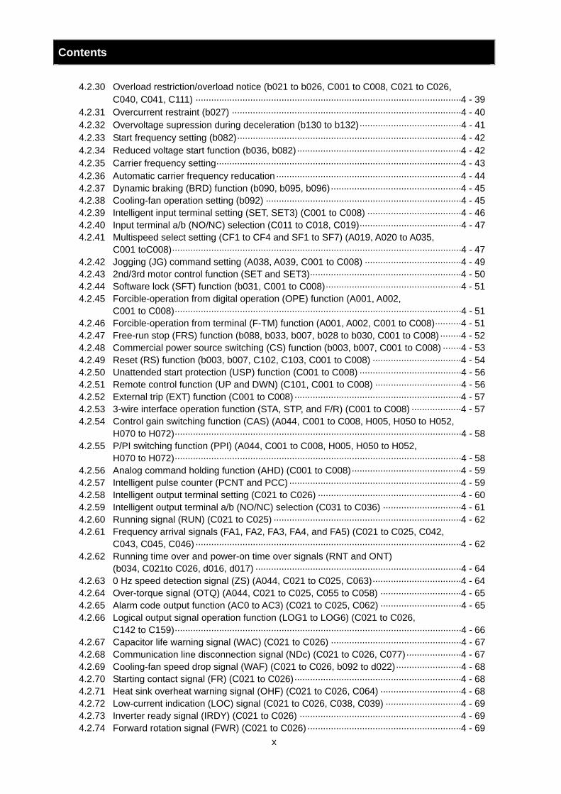
4.2.30 Overload restriction/overload notice (b021 to b026, C001 to C008, C021 to C026, C040, C041, C111) ······································································································4 - 39
4.2.31 Overcurrent restraint (b027) ························································································4 - 40 4.2.32 Overvoltage supression during deceleration (b130 to b132)·······································4 - 41 4.2.33 Start frequency setting (b082)······················································································4 - 42 4.2.34 Reduced voltage start function (b036, b082)·······························································4 - 42 4.2.35 Carrier frequency setting······························································································4 - 43 4.2.36 Automatic carrier frequency reducation·······································································4 - 44 4.2.37 Dynamic braking (BRD) function (b090, b095, b096)··················································4 - 45 4.2.38 Cooling-fan operation setting (b092) ···········································································4 - 45 4.2.39 Intelligent input terminal setting (SET, SET3) (C001 to C008) ····································4 - 46 4.2.40 Input terminal a/b (NO/NC) selection (C011 to C018, C019)·······································4 - 47 4.2.41 Multispeed select setting (CF1 to CF4 and SF1 to SF7) (A019, A020 to A035,
C001 toC008)···············································································································4 - 47 4.2.42 Jogging (JG) command setting (A038, A039, C001 to C008) ·····································4 - 49 4.2.43 2nd/3rd motor control function (SET and SET3)··························································4 - 50 4.2.44 Software lock (SFT) function (b031, C001 to C008)····················································4 - 51 4.2.45 Forcible-operation from digital operation (OPE) function (A001, A002,
C001 to C008)··············································································································4 - 51 4.2.46 Forcible-operation from terminal (F-TM) function (A001, A002, C001 to C008)··········4 - 51 4.2.47 Free-run stop (FRS) function (b088, b033, b007, b028 to b030, C001 to C008)········4 - 52 4.2.48 Commercial power source switching (CS) function (b003, b007, C001 to C008) ·······4 - 53 4.2.49 Reset (RS) function (b003, b007, C102, C103, C001 to C008) ··································4 - 54 4.2.50 Unattended start protection (USP) function (C001 to C008) ·······································4 - 56 4.2.51 Remote control function (UP and DWN) (C101, C001 to C008) ·································4 - 56 4.2.52 External trip (EXT) function (C001 to C008)································································4 - 57 4.2.53 3-wire interface operation function (STA, STP, and F/R) (C001 to C008) ···················4 - 57 4.2.54 Control gain switching function (CAS) (A044, C001 to C008, H005, H050 to H052,
H070 to H072)··············································································································4 - 58 4.2.55 P/PI switching function (PPI) (A044, C001 to C008, H005, H050 to H052,
H070 to H072)··············································································································4 - 58 4.2.56 Analog command holding function (AHD) (C001 to C008)··········································4 - 59 4.2.57 Intelligent pulse counter (PCNT and PCC) ··································································4 - 59 4.2.58 Intelligent output terminal setting (C021 to C026) ·······················································4 - 60 4.2.59 Intelligent output terminal a/b (NO/NC) selection (C031 to C036) ······························4 - 61 4.2.60 Running signal (RUN) (C021 to C025) ········································································4 - 62 4.2.61 Frequency arrival signals (FA1, FA2, FA3, FA4, and FA5) (C021 to C025, C042,
C043, C045, C046) ······································································································4 - 62 4.2.62 Running time over and power-on time over signals (RNT and ONT)
(b034, C021to C026, d016, d017) ···············································································4 - 64 4.2.63 0 Hz speed detection signal (ZS) (A044, C021 to C025, C063)··································4 - 64 4.2.64 Over-torque signal (OTQ) (A044, C021 to C025, C055 to C058) ·······························4 - 65 4.2.65 Alarm code output function (AC0 to AC3) (C021 to C025, C062) ·······························4 - 65 4.2.66 Logical output signal operation function (LOG1 to LOG6) (C021 to C026,
C142 to C159)··············································································································4 - 66 4.2.67 Capacitor life warning signal (WAC) (C021 to C026) ··················································4 - 67 4.2.68 Communication line disconnection signal (NDc) (C021 to C026, C077)·····················4 - 67 4.2.69 Cooling-fan speed drop signal (WAF) (C021 to C026, b092 to d022)·························4 - 68 4.2.70 Starting contact signal (FR) (C021 to C026)································································4 - 68 4.2.71 Heat sink overheat warning signal (OHF) (C021 to C026, C064) ·······························4 - 68 4.2.72 Low-current indication (LOC) signal (C021 to C026, C038, C039) ·····························4 - 69 4.2.73 Inverter ready signal (IRDY) (C021 to C026) ······························································4 - 69 4.2.74 Forward rotation signal (FWR) (C021 to C026)···························································4 - 69
Contents
xi
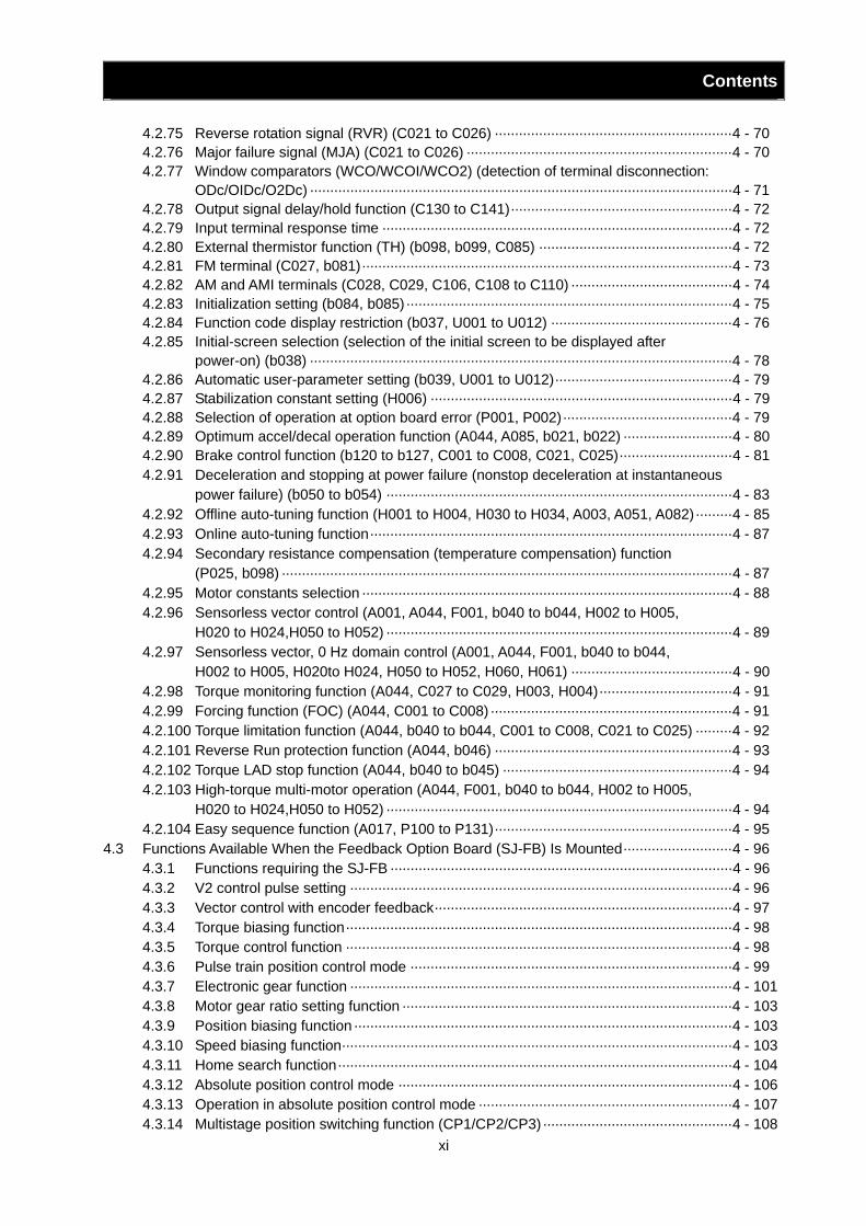
4.2.75 Reverse rotation signal (RVR) (C021 to C026) ···························································4 - 70 4.2.76 Major failure signal (MJA) (C021 to C026) ··································································4 - 70 4.2.77 Window comparators (WCO/WCOI/WCO2) (detection of terminal disconnection:
ODc/OIDc/O2Dc) ·········································································································4 - 71 4.2.78 Output signal delay/hold function (C130 to C141)·······················································4 - 72 4.2.79 Input terminal response time ·······················································································4 - 72 4.2.80 External thermistor function (TH) (b098, b099, C085) ················································4 - 72 4.2.81 FM terminal (C027, b081)····························································································4 - 73 4.2.82 AM and AMI terminals (C028, C029, C106, C108 to C110) ········································4 - 74 4.2.83 Initialization setting (b084, b085)·················································································4 - 75 4.2.84 Function code display restriction (b037, U001 to U012) ·············································4 - 76 4.2.85 Initial-screen selection (selection of the initial screen to be displayed after
power-on) (b038) ·········································································································4 - 78 4.2.86 Automatic user-parameter setting (b039, U001 to U012)············································4 - 79 4.2.87 Stabilization constant setting (H006) ···········································································4 - 79 4.2.88 Selection of operation at option board error (P001, P002)··········································4 - 79 4.2.89 Optimum accel/decal operation function (A044, A085, b021, b022) ···························4 - 80 4.2.90 Brake control function (b120 to b127, C001 to C008, C021, C025)····························4 - 81 4.2.91 Deceleration and stopping at power failure (nonstop deceleration at instantaneous
power failure) (b050 to b054) ······················································································4 - 83 4.2.92 Offline auto-tuning function (H001 to H004, H030 to H034, A003, A051, A082)·········4 - 85 4.2.93 Online auto-tuning function··························································································4 - 87 4.2.94 Secondary resistance compensation (temperature compensation) function
(P025, b098) ················································································································4 - 87 4.2.95 Motor constants selection ····························································································4 - 88 4.2.96 Sensorless vector control (A001, A044, F001, b040 to b044, H002 to H005,
H020 to H024,H050 to H052) ······················································································4 - 89 4.2.97 Sensorless vector, 0 Hz domain control (A001, A044, F001, b040 to b044,
H002 to H005, H020to H024, H050 to H052, H060, H061) ········································4 - 90 4.2.98 Torque monitoring function (A044, C027 to C029, H003, H004)·································4 - 91 4.2.99 Forcing function (FOC) (A044, C001 to C008) ····························································4 - 91 4.2.100 Torque limitation function (A044, b040 to b044, C001 to C008, C021 to C025) ·········4 - 92 4.2.101 Reverse Run protection function (A044, b046) ···························································4 - 93 4.2.102 Torque LAD stop function (A044, b040 to b045) ·························································4 - 94 4.2.103 High-torque multi-motor operation (A044, F001, b040 to b044, H002 to H005,
H020 to H024,H050 to H052) ······················································································4 - 94 4.2.104 Easy sequence function (A017, P100 to P131)···························································4 - 95
4.3 Functions Available When the Feedback Option Board (SJ-FB) Is Mounted···························4 - 96 4.3.1 Functions requiring the SJ-FB ·····················································································4 - 96 4.3.2 V2 control pulse setting ·······························································································4 - 96 4.3.3 Vector control with encoder feedback··········································································4 - 97 4.3.4 Torque biasing function································································································4 - 98 4.3.5 Torque control function ································································································4 - 98 4.3.6 Pulse train position control mode ················································································4 - 99 4.3.7 Electronic gear function ·······························································································4 - 101 4.3.8 Motor gear ratio setting function ··················································································4 - 103 4.3.9 Position biasing function······························································································4 - 103 4.3.10 Speed biasing function·································································································4 - 103 4.3.11 Home search function··································································································4 - 104 4.3.12 Absolute position control mode ···················································································4 - 106 4.3.13 Operation in absolute position control mode ·······························································4 - 107 4.3.14 Multistage position switching function (CP1/CP2/CP3)···············································4 - 108
Contents
xii
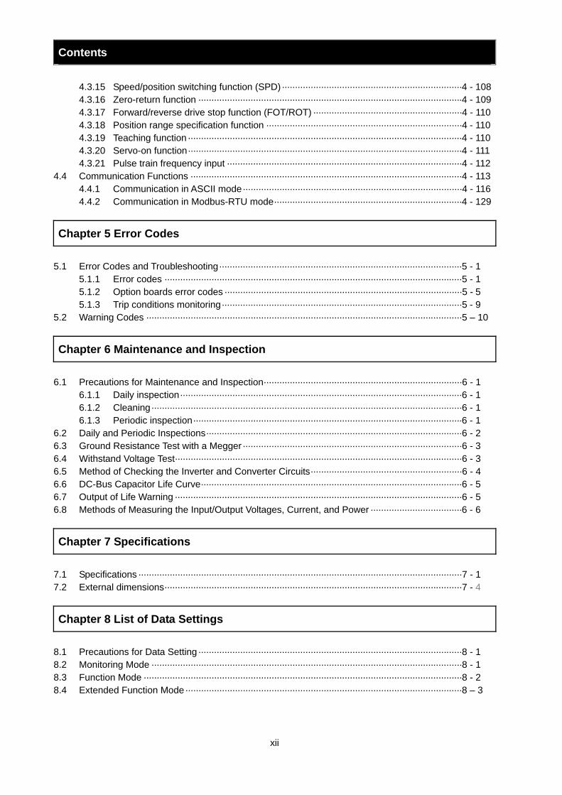
4.3.15 Speed/position switching function (SPD)·····································································4 - 108 4.3.16 Zero-return function ·····································································································4 - 109 4.3.17 Forward/reverse drive stop function (FOT/ROT) ·························································4 - 110 4.3.18 Position range specification function ···········································································4 - 110 4.3.19 Teaching function ·········································································································4 - 110 4.3.20 Servo-on function·········································································································4 - 111 4.3.21 Pulse train frequency input ··························································································4 - 112
4.4 Communication Functions ········································································································4 - 113 4.4.1 Communication in ASCII mode····················································································4 - 116 4.4.2 Communication in Modbus-RTU mode········································································4 - 129
Chapter 5 Error Codes 5.1 Error Codes and Troubleshooting·····························································································5 - 1
5.1.1 Error codes ··················································································································5 - 1 5.1.2 Option boards error codes ···························································································5 - 5 5.1.3 Trip conditions monitoring····························································································5 - 9
5.2 Warning Codes ·························································································································5 – 10
Chapter 6 Maintenance and Inspection 6.1 Precautions for Maintenance and Inspection············································································6 - 1
6.1.1 Daily inspection············································································································6 - 1 6.1.2 Cleaning·······················································································································6 - 1 6.1.3 Periodic inspection·······································································································6 - 1
6.2 Daily and Periodic Inspections··································································································6 - 2 6.3 Ground Resistance Test with a Megger····················································································6 - 3 6.4 Withstand Voltage Test··············································································································6 - 3 6.5 Method of Checking the Inverter and Converter Circuits··························································6 - 4 6.6 DC-Bus Capacitor Life Curve····································································································6 - 5 6.7 Output of Life Warning ··············································································································6 - 5 6.8 Methods of Measuring the Input/Output Voltages, Current, and Power ···································6 - 6
Chapter 7 Specifications 7.1 Specifications ····························································································································7 - 1 7.2 External dimensions··················································································································7 - 4
Chapter 8 List of Data Settings 8.1 Precautions for Data Setting·····································································································8 - 1 8.2 Monitoring Mode ·······················································································································8 - 1 8.3 Function Mode ··························································································································8 - 2 8.4 Extended Function Mode··········································································································8 – 3

Contents
xiii
Index
Index··············································································································································· Index - 1
Chapter 1 Overview This chapter describes the inspection of the purchased product, the product warranty, and the names of parts.
1.1 Inspection of the Purchased Product ··············· 1 - 1 1.2 Method of Inquiry and Product Warranty ········· 1 - 2 1.3 Exterior Views and Names of Parts ················· 1 - 3
Overview

Chapter 1 Overview
1 - 1
Overview
1.1 Inspection of the Purchased Product 1.1.1 Inspecting the product
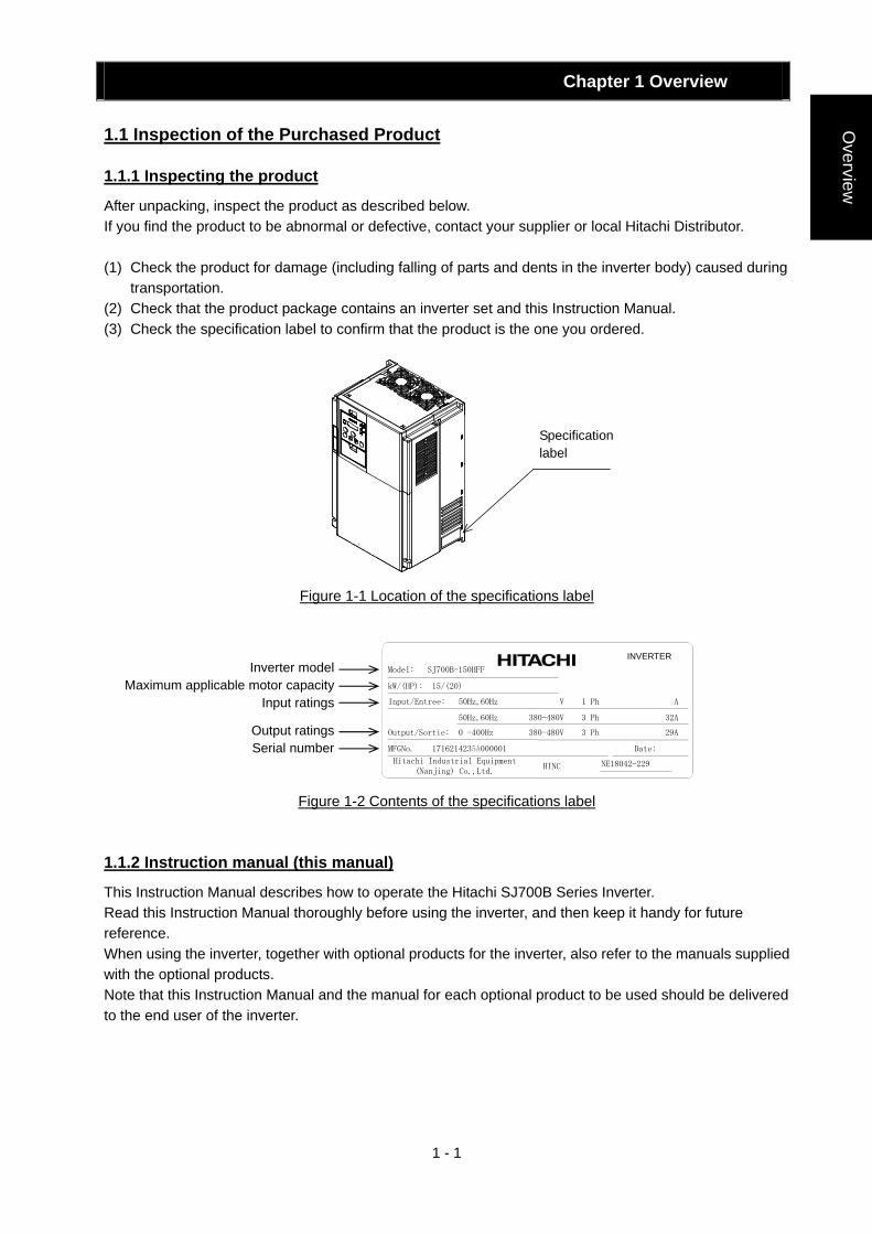
After unpacking, inspect the product as described below. If you find the product to be abnormal or defective, contact your supplier or local Hitachi Distributor. (1) Check the product for damage (including falling of parts and dents in the inverter body) caused during
transportation. (2) Check that the product package contains an inverter set and this Instruction Manual. (3) Check the specification label to confirm that the product is the one you ordered.
Figure 1-1 Location of the specifications label
Figure 1-2 Contents of the specifications label
1.1.2 Instruction manual (this manual)
This Instruction Manual describes how to operate the Hitachi SJ700B Series Inverter. Read this Instruction Manual thoroughly before using the inverter, and then keep it handy for future reference. When using the inverter, together with optional products for the inverter, also refer to the manuals supplied with the optional products. Note that this Instruction Manual and the manual for each optional product to be used should be delivered to the end user of the inverter.
INVERTER
Specification label
kW/(HP): 15/(20)
Model: SJ700B-150HFF
50Hz,60Hz 380-480V 3 Ph 32A
Output/Sortie: 0 -400Hz 380-480V 3 Ph 29A
Input/Entree: 50Hz,60Hz V 1 Ph A
MFGNo. 1716214235A000001 Date:
Hitachi Industrial Equipment (Nanjing) Co.,Ltd.
HINC NE18042-229
Inverter model Maximum applicable motor capacity
Input ratings
Output ratings Serial number
Chapter 1 Overview
1 - 2
Ove
rvie
w 1.2 Method of Inquiry and Product Warranty
1.2.1 Method of inquiry
For an inquiry about product damage or faults or a question about the product, notify your supplier of the following information: (1) Model of your inverter (2) Serial number (MFG No.) (3) Date of purchase (4) Content of inquiry
- Location and condition of damage - Content of your question
1.2.2 Product warranty
The product will be warranted for one year after the date of purchase. Even within the warranty period, repair of a product fault will not be covered by the warranty (but the repair will be at your own cost) if: (1) the fault has resulted from incorrect usage not conforming to the instructions given in this Instruction
Manual or the repair or modification of the product carried out by an unqualified person, (2) the fault has resulted from a cause not attributable to the delivered product, (3) the fault has resulted from use beyond the limits of the product specifications, or (4) the fault has resulted from disaster or other unavoidable events. The warranty will only apply to the delivered inverter and excludes all damage to other equipment and facilities induced by any fault of the inverter. The warranty is effective only in Japan. Repair at the user's charge Following the one-year warranty period, any examination and repair of the product will be accepted at your charge. Even during the warranty period, examination and repairs of faults, subject to the above scope of the warranty disclaimer, will be available at charge. To request a repair at your charge, contact your supplier or local Hitachi Distributor. The Hitachi Distributors are listed on the back cover of this Instruction Manual. 1.2.3 Warranty Terms
The warranty period under normal installation and handling conditions shall be two (2) years from the date of manufacture (“DATE” on product nameplate), or one (1) year from the date of installation, whichever occurs first. The warranty shall cover the repair or replacement, at Hitachi’s sole discretion, of ONLY the inverter that was installed. (1) Service in the following cases, even within the warranty period, shall be charged to the purchaser:
a. Malfunction or damage caused by mis-operation or modification or improper repair b. Malfunction or damage caused by a drop after purchase and transportation c. Malfunction or damage caused by fire, earthquake, flood, lightening, abnormal input voltage,
contamination, or other natural disasters (2) When service is required for the product at your work site, all expenses associated with field repair
shall be charged to the purchaser. (3) Always keep this manual handy; please do not loose it. Please contact your Hitachi distributor to
purchase replacement or additional manuals.
Chapter 1 Overview
1 - 3
Overview
1.3 Exterior Views and Names of Parts
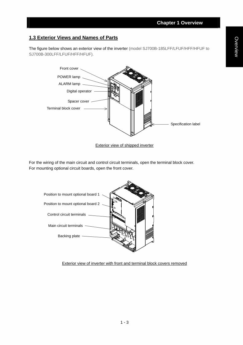
The figure below shows an exterior view of the inverter (model SJ700B-185LFF/LFUF/HFF/HFUF to SJ700B-300LFF/LFUF/HFF/HFUF).
Exterior view of shipped inverter For the wiring of the main circuit and control circuit terminals, open the terminal block cover. For mounting optional circuit boards, open the front cover.
Exterior view of inverter with front and terminal block covers removed
Front cover
POWER lamp
ALARM lamp
Terminal block cover
Spacer cover
Digital operator
Specification label
Position to mount optional board 1
Main circuit terminals
Backing plate
Control circuit terminals
Position to mount optional board 2
Chapter 2 Installation and Wiring This chapter describes how to install the inverter and the wiring of main circuit and control signal terminals with typical examples of wiring.
2.1 Installation ························································ 2 - 1 2.2 Wiring ······························································· 2 - 5
Installation and W
iring

Chapter 2 Installation and Wiring
2 - 1
Installation and W
iring
2.1 Installation
CAUTION
- Install the inverter on a non-flammable surface, e.g., metal. Otherwise, you run the risk of fire. - Do not place flammable materials near the installed inverter. Otherwise, you run the risk of fire. - When carrying the inverter, do not hold its top cover. Otherwise, you run the risk of injury by dropping
the inverter. - Prevent foreign matter (e.g., cut pieces of wire, sputtering welding materials, iron chips, wire, and
dust) from entering the inverter. Otherwise, you run the risk of fire. - Install the inverter on a structure able to bear the weight specified in this Instruction Manual.
Otherwise, you run the risk of injury due to the inverter falling. - Install the inverter on a vertical wall that is free of vibrations. Otherwise, you run the risk of injury due
to the inverter falling. - Do not install and operate the inverter if it is damaged or its parts are missing. Otherwise, you run the
risk of injury. - Install the inverter in a well-ventilated indoor site not exposed to direct sunlight. Avoid places where
the inverter is exposed to high temperature, high humidity, condensation, dust, explosive gases, corrosive gases, flammable gases, grinding fluid mist, or salt water. Otherwise, you run the risk of fire.
- The inverter is precision equipment. Do not allow it to fall or be subject to high impacts, step on it, or place a heavy load on it. Doing so may cause the inverter to fail.
!
Chapter 2 Installation and Wiring
2 - 2
Inst
alla
tion
and
Wiri
ng
2.1.1 Precautions for installation
(1) Transportation The inverter uses plastic parts. When carrying the inverter, handle it carefully to prevent damage to the
parts. Do not carry the inverter by holding the front or terminal block cover. Doing so may cause the inverter
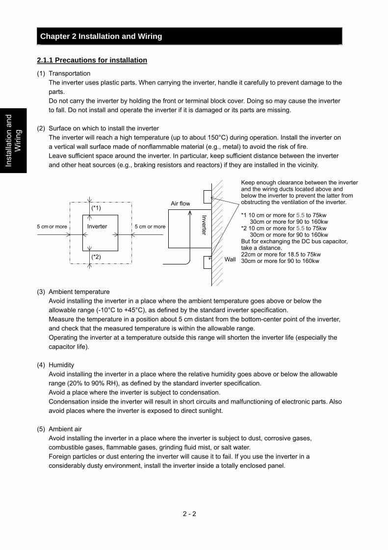
to fall. Do not install and operate the inverter if it is damaged or its parts are missing. (2) Surface on which to install the inverter The inverter will reach a high temperature (up to about 150°C) during operation. Install the inverter on
a vertical wall surface made of nonflammable material (e.g., metal) to avoid the risk of fire. Leave sufficient space around the inverter. In particular, keep sufficient distance between the inverter
and other heat sources (e.g., braking resistors and reactors) if they are installed in the vicinity. (3) Ambient temperature Avoid installing the inverter in a place where the ambient temperature goes above or below the
allowable range (-10°C to +45°C), as defined by the standard inverter specification. Measure the temperature in a position about 5 cm distant from the bottom-center point of the inverter,
and check that the measured temperature is within the allowable range. Operating the inverter at a temperature outside this range will shorten the inverter life (especially the
capacitor life). (4) Humidity Avoid installing the inverter in a place where the relative humidity goes above or below the allowable
range (20% to 90% RH), as defined by the standard inverter specification. Avoid a place where the inverter is subject to condensation. Condensation inside the inverter will result in short circuits and malfunctioning of electronic parts. Also
avoid places where the inverter is exposed to direct sunlight. (5) Ambient air Avoid installing the inverter in a place where the inverter is subject to dust, corrosive gases,
combustible gases, flammable gases, grinding fluid mist, or salt water. Foreign particles or dust entering the inverter will cause it to fail. If you use the inverter in a
considerably dusty environment, install the inverter inside a totally enclosed panel.
5 cm or more 5 cm or more
(*1)
(*2)
Inverter
Keep enough clearance between the inverter and the wiring ducts located above and below the inverter to prevent the latter from obstructing the ventilation of the inverter. *1 10 cm or more for 5.5 to 75kw
30cm or more for 90 to 160kw *2 10 cm or more for 5.5 to 75kw 30cm or more for 90 to 160kw But for exchanging the DC bus capacitor, take a distance. 22cm or more for 18.5 to 75kw 30cm or more for 90 to 160kw
Inverter
Air flow
Wall
Chapter 2 Installation and Wiring
2 - 3
Installation and W
iring
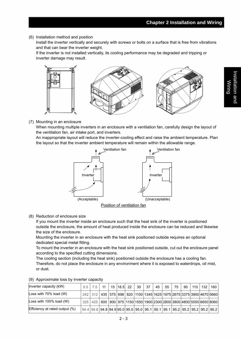
(6) Installation method and position Install the inverter vertically and securely with screws or bolts on a surface that is free from vibrations
and that can bear the inverter weight. If the inverter is not installed vertically, its cooling performance may be degraded and tripping or
inverter damage may result.
(7) Mounting in an enclosure When mounting multiple inverters in an enclosure with a ventilation fan, carefully design the layout of
the ventilation fan, air intake port, and inverters. An inappropriate layout will reduce the inverter-cooling effect and raise the ambient temperature. Plan
the layout so that the inverter ambient temperature will remain within the allowable range.
Position of ventilation fan (8) Reduction of enclosure size If you mount the inverter inside an enclosure such that the heat sink of the inverter is positioned
outside the enclosure, the amount of heat produced inside the enclosure can be reduced and likewise the size of the enclosure.
Mounting the inverter in an enclosure with the heat sink positioned outside requires an optional dedicated special metal fitting.
To mount the inverter in an enclosure with the heat sink positioned outside, cut out the enclosure panel according to the specified cutting dimensions.
The cooling section (including the heat sink) positioned outside the enclosure has a cooling fan. Therefore, do not place the enclosure in any environment where it is exposed to waterdrops, oil mist, or dust.
(9) Approximate loss by inverter capacity
Inverter capacity (kW) 5.5 7.5 11 15 18.5 22 30 37 45 55 75 90 110 132 160
Loss with 70% load (W) 242 312 435 575 698 820 1100 1345 1625 1975 2675 3375 3900 4670 5660
Loss with 100% load (W) 325 425 600 800 975 1150 1550 1900 2300 2800 3800 4800 5550 6650 8060
Efficiency at rated output (%) 94.4 94.6 94.8 94.9 95.0 95.0 95.0 95.1 95.1 95.1 95.2 95.2 95.2 95.2 95.2
(Unacceptable)
Ventilation fan
Inverter
(Acceptable)
Ventilation fan
Inverter
Chapter 2 Installation and Wiring
2 - 4
Inst
alla
tion
and
Wiri
ng Section to be cut off
Joint
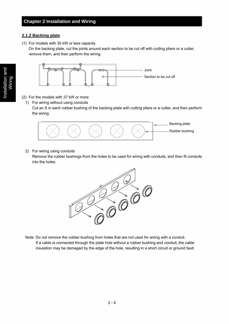
2.1.2 Backing plate
(1) For models with 30 kW or less capacity On the backing plate, cut the joints around each section to be cut off with cutting pliers or a cutter,
remove them, and then perform the wiring. (2) For the models with 37 kW or more
1) For wiring without using conduits Cut an X in each rubber bushing of the backing plate with cutting pliers or a cutter, and then perform
the wiring.
2) For wiring using conduits Remove the rubber bushings from the holes to be used for wiring with conduits, and then fit conduits
into the holes.
Note: Do not remove the rubber bushing from holes that are not used for wiring with a conduit. If a cable is connected through the plate hole without a rubber bushing and conduit, the cable
insulation may be damaged by the edge of the hole, resulting in a short circuit or ground fault.
Backing plate
Rubber bushing
Chapter 2 Installation and Wiring
2 - 5
Installation and W
iring
2.2 Wiring
WARNING
- Be sure to ground the inverter. Otherwise, you run the risk of electric shock or fire. - Commit wiring work to a qualified electrician. Otherwise, you run the risk of electric shock or fire. - Before wiring, make sure that the power supply is off. Otherwise, you run the risk of electric shock or
fire. - Perform wiring only after installing the inverter. Otherwise, you run the risk of electric shock or injury. - Do not remove rubber bushings from the wiring section. Otherwise, the edges of the wiring cover may
damage the wire, resulting in a short circuit or ground fault.
CAUTION
- Make sure that the voltage of AC power supply matches the rated voltage of your inverter. Otherwise, you run the risk of injury or fire.
- Do not input single-phase power into the inverter. Otherwise, you run the risk of fire. - Do not connect AC power supply to any of the output terminals (U, V, and W). Otherwise, you run the
risk of injury or fire. - Do not connect a resistor directly to any of the DC terminals (PD, P, and N). Otherwise, you run the
risk of fire. - Connect an earth-leakage breaker to the power input circuit. Otherwise, you run the risk of fire. - Use only the power cables, earth-leakage breaker, and magnetic contactors that have the specified
capacity (ratings). Otherwise, you run the risk of fire. - Do not use the magnetic contactor installed on the primary and secondary sides of the inverter to stop
its operation. - Tighten each screw to the specified torque. No screws must be left loose. Otherwise, you run the risk
of fire. - Before operating, slide switch SW1 in the inverter, be sure to turn off the power supply. Otherwise, you
run the risk of electric shock and injury. - Since the inverter supports two modes of cooling-fan operation, the inverter power is not always off,
even when the cooling fan is stopped. Therefore, be sure to confirm that the power supply is off before wiring. Otherwise, you run the risk of electric shock and injury.
!
!
Chapter 2 Installation and Wiring
2 - 6
Insta
llatio
n a
nd
Wirin
g
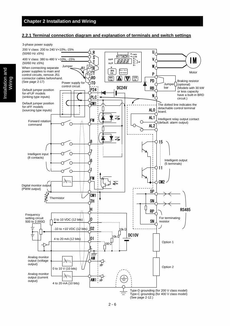
2.2.1 Terminal connection diagram and explanation of terminals and switch settings
3-phase power supply
200 V class: 200 to 240 V+10%,-15%
(50/60 Hz ±5%)
400 V class: 380 to 480 V +10%, -15%
(50/60 Hz ±5%) Jumper
When connecting separate power supplies to main and control circuits, remove J51 connector cables beforehand. (See page 2-17) Power supply for
control circuit
Forward rotation command
Intelligent input (8 contacts)
Digital monitor output (PWM output)
Thermistor
Frequency setting circuit 500 to 2,000Ω
0 to 10 VDC (12 bits)
-10 to +10 VDC (12 bits)
4 to 20 mA (12 bits)
Analog monitor output (voltage output)
Analog monitor output (current output)
0 to 10 V (10 bits)
4 to 20 mA (10 bits)
Motor
Jumper bar
Braking resistor (optional) (Models with 30 kW or less capacity have a built-in BRD circuit.)
The dotted line indicates the detachable control terminal board.
Intelligent relay output contact (default: alarm output)
Intelligent output (5 terminals)
For terminating resistor
Option 1
Option 2
Type-D grounding (for 200 V class model) Type-C grounding (for 400 V class model) (See page 2-12.)
PLC
P24 DC24V
CM1
R
S T
R0
T0
U
V
W
P
PD
RB
N
FW
7
6
1
8
FM
CM1
H
O
O2
OI
L
AM
AMI
SP
SN
RP
SN
RS485
AL0 AL1 AL2
1 2
HITACHI POWER
ALARM Hz
V
A
% kW
RUN
PRG
運転
RUN
機能
FUNC 記憶
STR
停止/リセット
DC10V
100Ω
10kΩ
10kΩ
15
11
CM2
R T
TH
J51
STOP/RESET
IM
Default jumper position for-xFUF models (sinking type inputs)
Default jumper position for-xFF models (sourcing type inputs)
Chapter 2 Installation and Wiring
2 - 7
Installation and W
iring
(1) Explanation of main circuit terminals
Symbol Terminal name Description R, S, T
(L1, L2, L3) Main power input Connect to the AC power supply. Leave these terminals unconnected when using a regenerative converter (HS900 series).
U, V, W (T1, T2, T3) Inverter output Connect a 3-phase motor.
PD, P (+1, +) DC reactor connection Remove the jumper from terminals PD and P, and connect the optional power factor reactor
(DCL). P, RB
(+, RB) External braking resistor connection
Connect the optional external braking resistor. (The RB terminal is provided on models with 30 kW or less capacity.)
P, N (+, -)
Dynamic braking unit connection Connect the optional dynamic braking unit (BRD).
G Inverter ground Connect to ground for grounding the inverter chassis by type-D grounding (for 200 V class models) or type-C grounding (for 400 V class models).
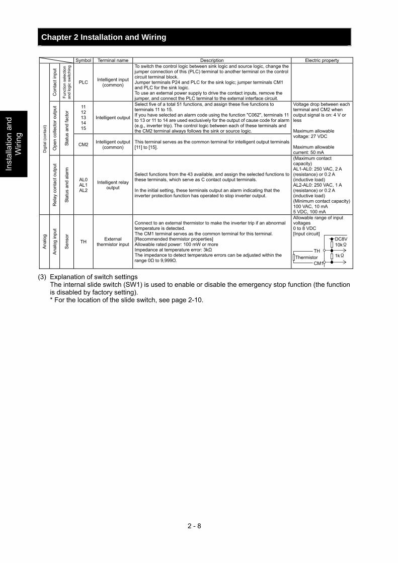
(2) Explanation of control circuit terminals Symbol Terminal name Description Electric property
L Analog power
supply (common)
This common terminal supplies power to frequency command terminals (O, O2, and OI) and analog output terminals (AM and AMI). Do not ground this terminal.
Pow
er
supp
ly
H Frequency
setting power supply
This terminal supplies 10 VDC power to the O, O2, OI terminals. Allowable load current: 20 mA or less
O Frequency command (voltage)
Input a voltage (0 to 10 VDC) as a frequency command. 10 V specifies the maximum frequency. To specify the maximum frequency with a voltage of 10 V or less, set the voltage using function "A014".
Input impedance: 10kΩ Allowable input voltages: -0.3 to +12 VDC
O2
Auxiliary frequency command (voltage)
Input a voltage (0 to ±10 VDC) as a signal to be added to the frequency command input from the O or OI terminal. You can input an independent frequency command from this terminal (O2 terminal) alone by changing the setting.
Input impedance: 10kΩ Allowable input voltages: 0 to ±12 VDC
Freq
uenc
y se
tting
inpu
t
OI Frequency command (current)
Input a current (4 to 20 mA DC) as a frequency command. 20 mA specifies the maximum frequency. The OI signal is valid only when the AT signal is on. Assign the AT function to an intelligent input terminal.
Input impedance: 10kΩ Maximum allowable current: 24 mA
AM Analog monitor (voltage)
This terminal outputs one of the selected "0 to 10 VDC voltage output" monitoring items. The monitoring items available for selection include output frequency, output current, output torque (signed or unsigned), output voltage, input power, electronic thermal overload, LAD frequency, motor temperature, heat sink temperature, and general output.
Maximum allowable current: 2 mA Output voltage accuracy: +/-10% (Ta=25+/-10 degrees C)
Ana
log
Mon
itor o
utpu
t
AMI Analog monitor (current)
This terminal outputs one of the selected "4 to 20 mA DC current output" monitoring items. The monitoring items available for selection include output frequency, output current, output torque (unsigned), output voltage, input power, electronic thermal overload, LAD frequency, motor temperature, heat sink temperature, and general output.
Allowable load impedance: 250Ω or less Output current accuracy: +/-10% (Ta=25+/-10 degrees C)
Mon
itor o
utpu
t
FM Digital monitor (voltage)
This terminal outputs one of the selected "0 to 10 VDC voltage output (PWM output mode)" monitoring items. The monitoring items available for selection include output frequency, output current, output torque (unsigned), output voltage, input power, electronic thermal overload, LAD frequency, motor temperature, heat sink temperature, general output, digital output frequency, and digital current monitor. For the items "digital output frequency" and "digital current monitor," this terminal outputs a digital pulse signal at 0/10 VDC with a duty ratio of 50%.
Maximum allowable current: 1.2 mA Maximum frequency: 3.6 kHz
P24 Interface power supply
This terminal supplies 24 VDC power for contact input signals. If the source logic is selected, this terminal is used as a common contact input terminal.
Maximum allowable output current: 100 mA
Pow
er s
uppl
y
CM1 Interface power
supply (common)
This common terminal supplies power to the interface power supply (P24), thermistor input (TH), and digital monitor (FM) terminals. If the sink logic is selected, this terminal is used as a common contact input terminal. Do not ground this terminal.
Ope
ratio
n
com
man
d
FW Forward rotation command
Turn on this FW signal to start the forward rotation of the motor; turn it off to stop forward rotation after deceleration.
Dig
ital (
cont
act)
Con
tact
inpu
t
Func
tion
sele
ctio
n an
d lo
gic
switc
hing
1 2 3 4 5 6 7 8
Intelligent input
Select eight of a total 60 functions, and assign these eight functions to terminals 1 to 8. Note: If the emergency stop function is used, terminals 1 and 3 are used exclusively for the function. For details, see Item (3), "Emergency stop function" (on page 2-8).
[Conditions for turning contact input on] Voltage across input and PLC: 18 VDC or more Input impedance between input and PLC: 4.7kΩ Maximum allowable voltageacross input and PLC: 27 VDC Load current with 27 VDC power: about 5.6 mA Minimum hold time FW and RV: 10msec Other: 40msec
Chapter 2 Installation and Wiring
2 - 8
Inst
alla
tion
and
Wiri
ng
Symbol Terminal name Description Electric property
Con
tact
inpu
t
Func
tion
sele
ctio
n an
d lo
gic
switc
hing
PLC Intelligent input (common)
To switch the control logic between sink logic and source logic, change the jumper connection of this (PLC) terminal to another terminal on the control circuit terminal block. Jumper terminals P24 and PLC for the sink logic; jumper terminals CM1 and PLC for the sink logic. To use an external power supply to drive the contact inputs, remove the jumper, and connect the PLC terminal to the external interface circuit.
11 12 13 14 15
Intelligent output
Select five of a total 51 functions, and assign these five functions to terminals 11 to 15. If you have selected an alarm code using the function "C062", terminals 11 to 13 or 11 to 14 are used exclusively for the output of cause code for alarm (e.g., inverter trip). The control logic between each of these terminals and the CM2 terminal always follows the sink or source logic.
Ope
n co
llect
or o
utpu
t
Stat
us a
nd fa
ctor
CM2 Intelligent output (common)
This terminal serves as the common terminal for intelligent output terminals [11] to [15].
Voltage drop between each terminal and CM2 when output signal is on: 4 V or less Maximum allowable voltage: 27 VDC Maximum allowable current: 50 mA D
igita
l (co
ntac
t)
Rel
ay c
onta
ct o
utpu
t
Stat
us a
nd a
larm
AL0 AL1 AL2
Intelligent relay output
Select functions from the 43 available, and assign the selected functions to these terminals, which serve as C contact output terminals. In the initial setting, these terminals output an alarm indicating that the inverter protection function has operated to stop inverter output.
(Maximum contact capacity) AL1-AL0: 250 VAC, 2 A (resistance) or 0.2 A (inductive load) AL2-AL0: 250 VAC, 1 A (resistance) or 0.2 A (inductive load) (Minimum contact capacity)100 VAC, 10 mA 5 VDC, 100 mA
Ana
log
Ana
log
inpu
t
Sen
sor
TH External thermistor input
Connect to an external thermistor to make the inverter trip if an abnormal temperature is detected. The CM1 terminal serves as the common terminal for this terminal. [Recommended thermistor properties] Allowable rated power: 100 mW or more Impedance at temperature error: 3kΩ The impedance to detect temperature errors can be adjusted within the range 0Ω to 9,999Ω.
Allowable range of input voltages 0 to 8 VDC [Input circuit]
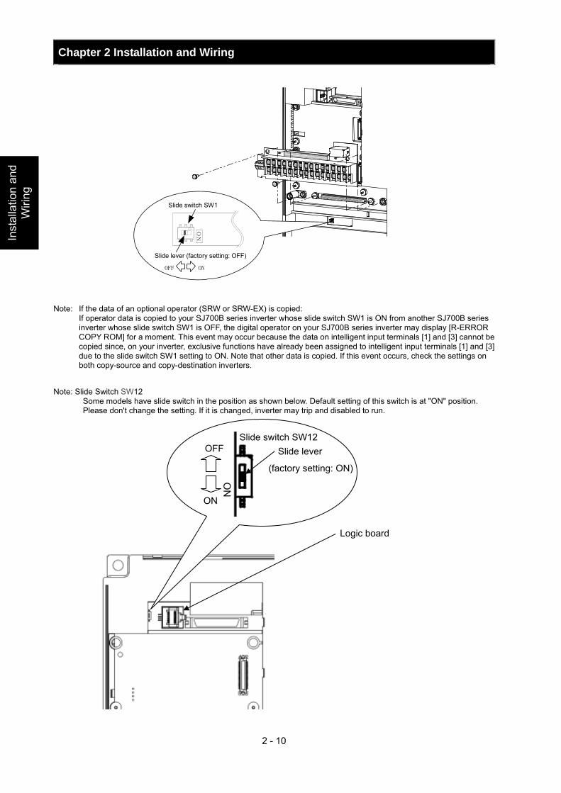
(3) Explanation of switch settings The internal slide switch (SW1) is used to enable or disable the emergency stop function (the function
is disabled by factory setting). * For the location of the slide switch, see page 2-10.
DC8V 10kΩ
1kΩCM1
TH Thermistor
Chapter 2 Installation and Wiring
2 - 9
Installation and W
iring
About the emergency stop function (disabled by the factory setting)
- The emergency stop function shuts off the inverter output (i.e. stops the switching operation of the main circuit elements) in response to a command from a hardware circuit via an intelligent input terminal without the operation by internal CPU software.
Note: The emergency stop function does not electrically shut off the inverter but merely stops the switching operation of the main circuit elements. Therefore, do not touch any terminals of the inverter or any power lines, e.g., motor cables. Otherwise, electric shock, injury, or ground fault may result.
- When the emergency stop function is enabled, intelligent input terminals 1 and 3 are used exclusively for this function, and no other functions can be assigned to these terminals. Even if other functions have been assigned to these terminals, these are automatically disabled and these terminals are used exclusively for the emergency stop function. Terminal [1] function:
This terminal always serves as the a (NO) contact for the reset (RS) signal. This signal resets the inverter and releases the inverter from the trip due to emergency stop (E37.*).
Terminal [3] function: This terminal always serves as the b (NC) contact for the emergency stop (EMR) signal. This signal shuts off the inverter output without the operation by internal CPU software. This signal makes the inverter trip due to emergency stop (E37.*).
Note: If intelligent input terminal 3 is left unconnected, the cable connected to the terminal is disconnected, or the signal logic is improper, the inverter trips due to emergency stop (E37.*). If this occurs, check and correct the wiring and signal logic, and then input the reset (RS) signal. Only the reset (RS) signal input from intelligent input terminal [1] can release the inverter from tripping due to emergency stop (E37.*). (The inverter cannot be released from the E37.* status by any operation from the digital operator.)
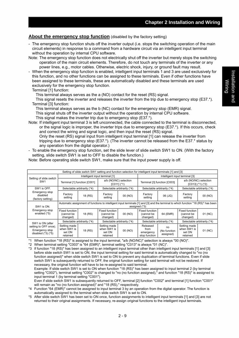
- To enable the emergency stop function, set the slide lever of slide switch SW1 to ON. (With the factory setting, slide switch SW1 is set to OFF to disable the function.)
Note: Before operating slide switch SW1, make sure that the input power supply is off.
Setting of slide switch SW1 setting and function selection for intelligent input terminals [1] and [3] Intelligent input terminal [1] Intelligent input terminal [3]
Setting of slide switch SW1 Terminal [1] function [C001] a/b (NO/NC) selection
[C011] (*1) Terminal [3] function [C003] a/b (NO/NC) selection [C013] (*1) (*2)
Selectable arbitrarily (*4) Selectable arbitrarily (*4) Selectable arbitrarily (*4) Selectable arbitrarily (*4) SW1 is OFF. Emergency stop
disabled (factory setting)
Factory setting 18 (RS) Factory
setting 00 (NO) Factory setting 06 (JG) Factory
setting 00 (NO)
Automatic assignment of functions to intelligent input terminals [1] and [3] and the terminal to which function "18 (RS)" has been assigned (*3) SW1 is ON.
Emergency stop enabled (*5)
Fixed function (cannot be changed)
18 (RS) Fixed function
(cannot be changed)
00 (NO) Fixed function
(cannot be changed)
64 (EMR) Fixed function
(cannot be changed)
01 (NC)
Selectable arbitrarily (*4) Selectable arbitrarily (*4) Selectable arbitrarily (*4) Selectable arbitrarily (*4) SW1 is ON (after setting to OFF once).
Emergency stop disabled (*3) (*5)
Setting made when SW1 is
set ON retained
18 (RS)
Setting made when SW1 is
set ON retained
00 (NO)
Released from
emergency stop function
no (No function assigned)
Setting made when SW1 is
set ON retained
01 (NC)
*1 When function "18 (RS)" is assigned to the input terminal, "a/b (NO/NC)" selection is always "00 (NO)". *2 When terminal setting "C003" is "64 (EMR)", terminal setting "C013" is always "01 (NC)". *3 If function "18 (RS)" has been assigned to an intelligent input terminal other than intelligent input terminals [1] and [3]
before slide switch SW1 is set to ON, the input terminal setting for said terminal is automatically changed to "no (no function assigned)" when slide switch SW1 is set to ON to prevent any duplication of terminal functions. Even if slide switch SW1 is subsequently returned to OFF, the original function setting for said terminal will not be restored. If necessary, the original function will have to be re-assigned to said terminal.
Example: If slide switch SW1 is set to ON when function "18 (RS)" has been assigned to input terminal 2 (by terminal setting "C002"), terminal setting "C002" is changed to "no (no function assigned)," and function "18 (RS)" is assigned to input terminal 1 (by terminal setting "C001").
Even if slide switch SW1 is subsequently returned to OFF, terminal [2] function "C002" and terminal [1] function "C001" will remain as "no (no function assigned)" and "18 (RS)," respectively.
*4 Function "64 (EMR)" cannot be assigned to input terminal 3 by an operation from the digital operator. The function is automatically assigned to the terminal when slide switch SW1 is set to ON.
*5 After slide switch SW1 has been set to ON once, function assignments to intelligent input terminals [1] and [3] are not returned to their original assignments. If necessary, re-assign original functions to the intelligent input terminals.
Chapter 2 Installation and Wiring
2 - 10
Inst
alla
tion
and
Wiri
ng
Note: If the data of an optional operator (SRW or SRW-EX) is copied: If operator data is copied to your SJ700B series inverter whose slide switch SW1 is ON from another SJ700B series
inverter whose slide switch SW1 is OFF, the digital operator on your SJ700B series inverter may display [R-ERROR COPY ROM] for a moment. This event may occur because the data on intelligent input terminals [1] and [3] cannot be copied since, on your inverter, exclusive functions have already been assigned to intelligent input terminals [1] and [3] due to the slide switch SW1 setting to ON. Note that other data is copied. If this event occurs, check the settings on both copy-source and copy-destination inverters.
Note: Slide Switch SW12
Some models have slide switch in the position as shown below. Default setting of this switch is at "ON" position. Please don't change the setting. If it is changed, inverter may trip and disabled to run.
ON
Slide switch SW1
OFF ON
Slide lever (factory setting: OFF)
Logic board
ON
OFF
ON
Slide lever
(factory setting: ON)
Slide switch SW12
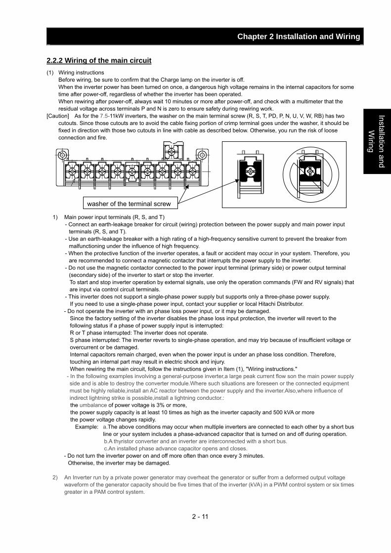
Chapter 2 Installation and Wiring
2 - 11
Installation and W
iring
2.2.2 Wiring of the main circuit (1) Wiring instructions Before wiring, be sure to confirm that the Charge lamp on the inverter is off. When the inverter power has been turned on once, a dangerous high voltage remains in the internal capacitors for some
time after power-off, regardless of whether the inverter has been operated. When rewiring after power-off, always wait 10 minutes or more after power-off, and check with a multimeter that the
residual voltage across terminals P and N is zero to ensure safety during rewiring work. [Caution] As for the 7.5-11kW inverters, the washer on the main terminal screw (R, S, T, PD, P, N, U, V, W, RB) has two
cutouts. Since those cutouts are to avoid the cable fixing portion of crimp terminal goes under the washer, it should be fixed in direction with those two cutouts in line with cable as described below. Otherwise, you run the risk of loose connection and fire.
1) Main power input terminals (R, S, and T) - Connect an earth-leakage breaker for circuit (wiring) protection between the power supply and main power input
terminals (R, S, and T). - Use an earth-leakage breaker with a high rating of a high-frequency sensitive current to prevent the breaker from
malfunctioning under the influence of high frequency. - When the protective function of the inverter operates, a fault or accident may occur in your system. Therefore, you
are recommended to connect a magnetic contactor that interrupts the power supply to the inverter. - Do not use the magnetic contactor connected to the power input terminal (primary side) or power output terminal
(secondary side) of the inverter to start or stop the inverter. To start and stop inverter operation by external signals, use only the operation commands (FW and RV signals) that are input via control circuit terminals.
- This inverter does not support a single-phase power supply but supports only a three-phase power supply. If you need to use a single-phase power input, contact your supplier or local Hitachi Distributor. - Do not operate the inverter with an phase loss power input, or it may be damaged. Since the factory setting of the inverter disables the phase loss input protection, the inverter will revert to the
following status if a phase of power supply input is interrupted: R or T phase interrupted: The inverter does not operate. S phase interrupted: The inverter reverts to single-phase operation, and may trip because of insufficient voltage or
overcurrent or be damaged. Internal capacitors remain charged, even when the power input is under an phase loss condition. Therefore,
touching an internal part may result in electric shock and injury. When rewiring the main circuit, follow the instructions given in Item (1), "Wiring instructions." - In the following examples involving a general-purpose inverter,a large peak current flow son the main power supply side and is able to destroy the converter module.Where such situations are foreseen or the connected equipment must be highly reliable,install an AC reactor between the power supply and the inverter.Also,where influence of indirect lightning strike is possible,install a lightning conductor.: the umbalance of power voltage is 3% or more, the power supply capacity is at least 10 times as high as the inverter capacity and 500 kVA or more the power voltage changes rapidly.
Example: a.The above conditions may occur when multiple inverters are connected to each other by a short bus line or your system includes a phase-advanced capacitor that is turned on and off during operation.
b.A thyristor converter and an inverter are interconnected with a short bus. c.An installed phase advance capacitor opens and closes.
- Do not turn the inverter power on and off more often than once every 3 minutes. Otherwise, the inverter may be damaged.
2) An Inverter run by a private power generator may overheat the generator or suffer from a deformed output voltage
waveform of the generator capacity should be five times that of the inverter (kVA) in a PWM control system or six times greater in a PAM control system.
washer of the terminal screw
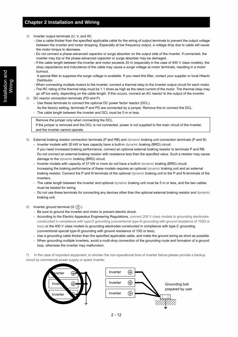
Chapter 2 Installation and Wiring
2 - 12
Inst
alla
tion
and
Wiri
ng
3) Inverter output terminals (U, V, and W) - Use a cable thicker than the specified applicable cable for the wiring of output terminals to prevent the output voltage
between the inverter and motor dropping. Especially at low frequency output, a voltage drop due to cable will cause the motor torque to decrease.
- Do not connect a phase-advanced capacitor or surge absorber on the output side of the inverter. If connected, the inverter may trip or the phase-advanced capacitor or surge absorber may be damaged.
- If the cable length between the inverter and motor exceeds 20 m (especially in the case of 400 V class models), the stray capacitance and inductance of the cable may cause a surge voltage at motor terminals, resulting in a motor burnout.
A special filter to suppress the surge voltage is available. If you need this filter, contact your supplier or local Hitachi Distributor.
- When connecting multiple motors to the inverter, connect a thermal relay to the inverter output circuit for each motor. - The RC rating of the thermal relay must be 1.1 times as high as the rated current of the motor. The thermal relay may
go off too early, depending on the cable length. If this occurs, connect an AC reactor to the output of the inverter. 4) DC reactor connection terminals (PD and P)
- Use these terminals to connect the optional DC power factor reactor (DCL). As the factory setting, terminals P and PD are connected by a jumper. Remove this to connect the DCL. - The cable length between the inverter and DCL must be 5 m or less.
Remove the jumper only when connecting the DCL. If the jumper is removed and the DCL is not connected, power is not supplied to the main circuit of the inverter, and the inverter cannot operate.
5) External braking resistor connection terminals (P and RB) and dynamic braking unit connection terminals (P and N)
- Inverter models with 30 kW or less capacity have a built-in dynamic braking (BRD) circuit. If you need increased braking performance, connect an optional external braking resistor to terminals P and RB. Do not connect an external braking resistor with resistance less than the specified value. Such a resistor may cause
damage to the dynamic braking (BRD) circuit. - Inverter models with capacity of 37 kW or more do not have a built-in dynamic braking (BRD) circuit. Increasing the braking performance of these models requires an optional dynamic braking unit and an external
braking resistor. Connect the P and N terminals of the optional dynamic braking unit to the P and N terminals of the inverters.
- The cable length between the inverter and optional dynamic braking unit must be 5 m or less, and the two cables must be twisted for wiring.
- Do not use these terminals for connecting any devices other than the optional external braking resistor and dynamic braking unit.
6) Inverter ground terminal (G )
- Be sure to ground the inverter and motor to prevent electric shock. - According to the Electric Apparatus Engineering Regulations, connect 200 V class models to grounding electrodes
constructed in compliance with type-D grounding (conventional type-III grounding with ground resistance of 100Ω or less) or the 400 V class models to grounding electrodes constructed in compliance with type-C grounding (conventional special type-III grounding with ground resistance of 10Ω or less).
- Use a grounding cable thicker than the specified applicable cable, and make the ground wiring as short as possible. - When grounding multiple inverters, avoid a multi-drop connection of the grounding route and formation of a ground
loop, otherwise the inverter may malfunction.
7) In the case of important equipment, to shorten the non-operational time of inverter failure,please provide a backup circuit by commercial power supply or spare inverter.
Inverter
Inverter
Inverter
Grounding bolt prepared by user
Inverter
Inverter
Inverter
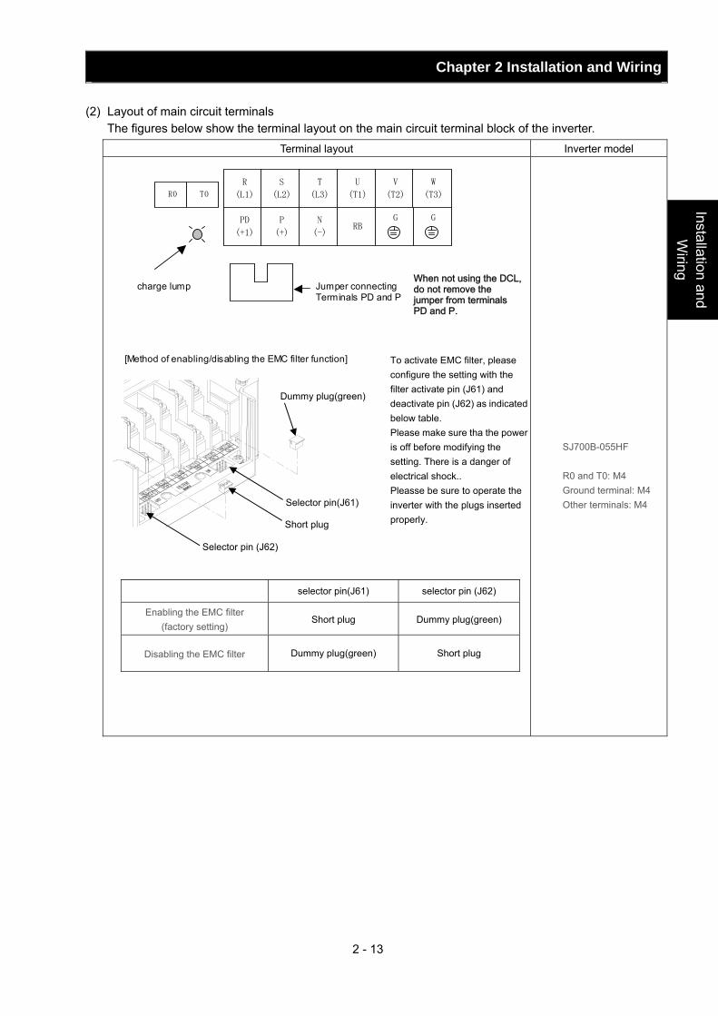
Chapter 2 Installation and Wiring
2 - 13
Installation and W
iring
(2) Layout of main circuit terminals The figures below show the terminal layout on the main circuit terminal block of the inverter.
Terminal layout Inverter model
SJ700B-055HF
R0 and T0: M4 Ground terminal: M4 Other terminals: M4
[Method of enabling/disabling the EMC filter function]
R
(L1)
S
(L2)
T
(L3)
PD
(+1)
P
(+)
N
(-)
U
(T1)
V
(T2)
W
(T3) R0 T0
charge lump
Jumper connecting Terminals PD and P
G
G
RB
To activate EMC filter, please configure the setting with the filter activate pin (J61) and deactivate pin (J62) as indicated below table. Please make sure tha the power is off before modifying the setting. There is a danger of electrical shock.. Pleasse be sure to operate the inverter with the plugs inserted properly.
Short plug
Dummy plug(green)
Selector pin(J61)
Selector pin (J62)
selector pin(J61) selector pin (J62)
Enabling the EMC filter (factory setting)
Short plug Dummy plug(green)
Disabling the EMC filter Dummy plug(green) Short plug
When not using the DCL, do not remove the jumper from terminals PD and P.
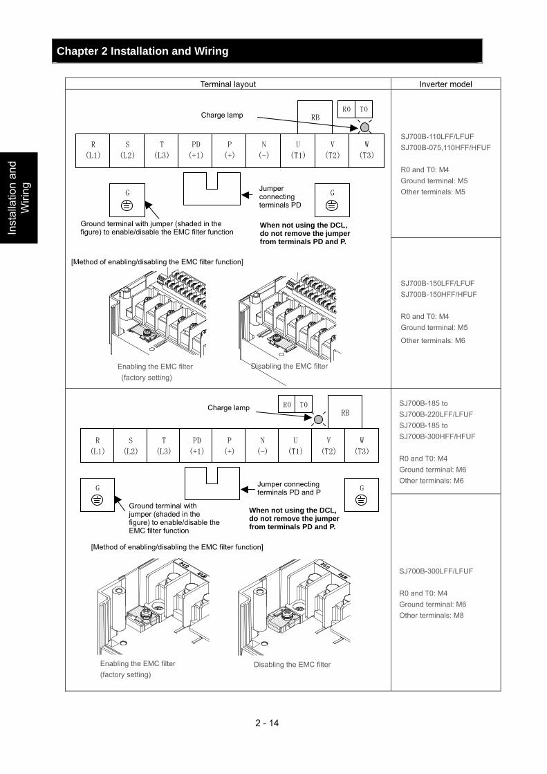
Chapter 2 Installation and Wiring
2 - 14
Inst
alla
tion
and
Wiri
ng
Terminal layout Inverter model
SJ700B-110LFF/LFUF SJ700B-075,110HFF/HFUF R0 and T0: M4 Ground terminal: M5 Other terminals: M5
RB
R
(L1)
S
(L2)
T
(L3)
PD
(+1)
P
(+)
N
(-)
U
(T1)
V
(T2)
W
(T3)
R0 T0 チャージランプ
PD-P短絡片
DCLを使用しない場合、
PD-P短絡片を取り外さ
ないでください。
G
EMCフィルタ機能
切り替え用短絡片
(斜線部)付き接地端子
G
SJ700B-150LFF/LFUF SJ700B-150HFF/HFUF R0 and T0: M4 Ground terminal: M5
Other terminals: M6
SJ700B-185 to SJ700B-220LFF/LFUF SJ700B-185 to SJ700B-300HFF/HFUF R0 and T0: M4 Ground terminal: M6 Other terminals: M6
RB
R
(L1)
S
(L2)
T
(L3)
PD
(+1)
P
(+)
N
(-)
U
(T1)
V
(T2)
W
(T3)
R0 T0
G G
SJ700B-300LFF/LFUF R0 and T0: M4 Ground terminal: M6 Other terminals: M8
Disabling the EMC filter
[Method of enabling/disabling the EMC filter function]
Enabling the EMC filter (factory setting)
Jumper connecting terminals PD
Ground terminal with jumper (shaded in the figure) to enable/disable the EMC filter function
When not using the DCL, do not remove the jumper from terminals PD and P.
Charge lamp
[Method of enabling/disabling the EMC filter function]
Charge lamp
Jumper connecting terminals PD and P
Ground terminal with jumper (shaded in the figure) to enable/disable the EMC filter function
When not using the DCL, do not remove the jumper from terminals PD and P.
Enabling the EMC filter (factory setting)
Disabling the EMC filter
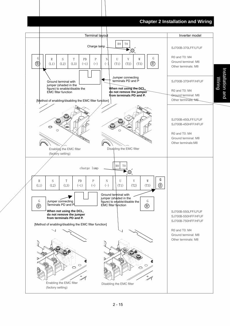
Chapter 2 Installation and Wiring
2 - 15
Installation and W
iring
Terminal layout Inverter model
SJ700B-370LFF/LFUF R0 and T0: M4 Ground terminal: M6 Other terminals: M8
SJ700B-370HFF/HFUF R0 and T0: M4 Ground terminal: M6 Other terminals: M6
R
(L1)
S
(L2)
T
(L3)
PD
(+1)
P
(+)
N
(-)
U
(T1)
V
(T2)
W
(T3)
R0 T0
G G
SJ700B-450LFF/LFUF SJ700B-450HFF/HFUF R0 and T0: M4 Ground terminal: M8 Other terminals:M8
R
(L1)
S
(L2)
T
(L3)
PD
(+1)
P
(+)
N
(-)
U
(T1)
V
(T2)
W
(T3)
R0 T0 charge lump
G G
SJ700B-550LFF/LFUF SJ700B-550HFF/HFUF SJ700B-750HFF/HFUF R0 and T0: M4 Ground terminal: M8 Other terminals: M8
[Method of enabling/disabling the EMC filter function]
Enabling the EMC filter (factory setting)
Disabling the EMC filter
When not using the DCL, do not remove the jumper from terminals PD and P.
Ground terminal with jumper (shaded in the figure) to enable/disable theEMC filter function
G
Jumper connecting Terminals PD and P
[Method of enabling/disabling the EMC filter function]
Enabling the EMC filter (factory setting)
Disabling the EMC filter
Charge lamp
When not using the DCL, do not remove the jumper from terminals PD and P.
Ground terminal with jumper (shaded in the figure) to enable/disable the EMC filter function
Jumper connecting terminals PD and P
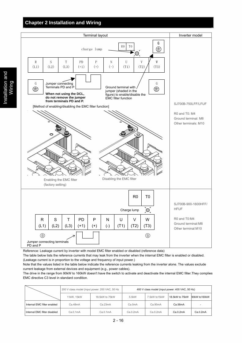
Chapter 2 Installation and Wiring
2 - 16
Inst
alla
tion
and
Wiri
ng
Reference: Leakage current by inverter with model EMC filter enabled or disabled (reference data) The table below lists the reference currents that may leak from the inverter when the internal EMC filter is enabled or disabled. (Leakage current is in proportion to the voltage and frequency of input power.) Note that the values listed in the table below indicate the reference currents leaking from the inverter alone. The values exclude current leakage from external devices and equipment (e.g., power cables). The drive in the range from 90kW to 160kW doesn't have the switch to activate and deactivate the internal EMC filter.They complies EMC directive C3 level in standard condition.
Terminal layout Inverter model
R
(L1)
S
(L2)
T
(L3)
PD
(+1)
P
(+)
N
(-)
U
(T1)
V
(T2)
W
(T3)
R0 T0 charge lump
G G
SJ700B-750LFF/LFUF R0 and T0: M4 Ground terminal: M8 Other terminals: M10
SJ700B-900-1600HFF/HFUF R0 and T0:M4 Ground terminal:M8 Other terminal:M10
200 V class model (input power: 200 VAC, 50 Hz 400 V class model (input power: 400 VAC, 50 Hz)
11kW, 15kW 18.5kW to 75kW 5.5kW 7.5kW to15kW 18.5kW to 75kW 90kW to160kW
Internal EMC filter enabled Ca.48mA Ca.23mA Ca.5mA Ca.95mA Ca.56mA -
Internal EMC filter disabled Ca.0.1mA Ca.0.1mA Ca.0.2mA Ca.0.2mA Ca.0.2mA Ca.0.2mA
When not using the DCL, do not remove the jumper from terminals PD and P.
Ground terminal with jumper (shaded in the figure) to enable/disable theEMC filter function
Jumper connecting Terminals PD and P
G
[Method of enabling/disabling the EMC filter function]
Enabling the EMC filter (factory setting)
Disabling the EMC filter
R (L1)
S (L2)
T (L3)
PD (+1)
P (+)
N (-)
U (T1)
V (T2)
W (T3)
R0 T0
Jumper connecting terminals PD and P
Charge lump
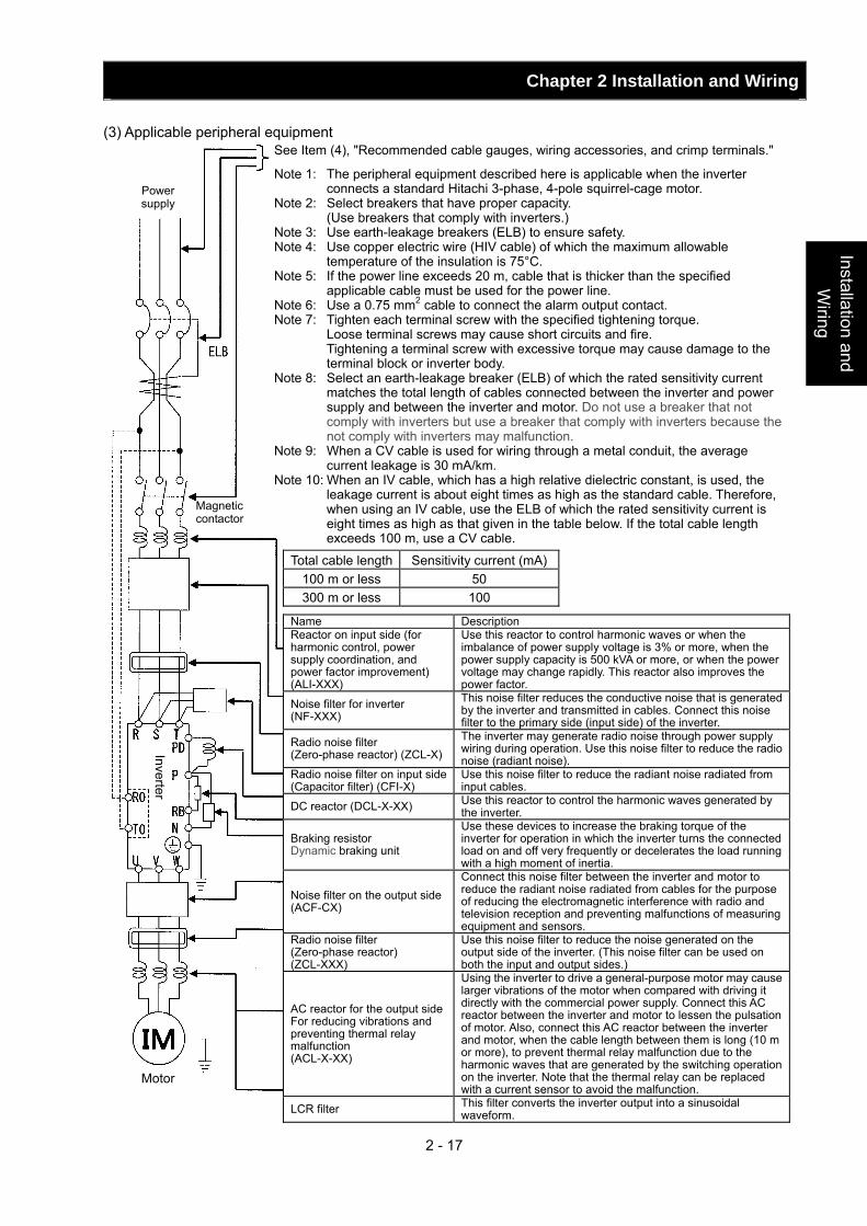
Chapter 2 Installation and Wiring
2 - 17
Installation and W
iring
Power supply
Magnetic contactor
Motor
Inverter
(3) Applicable peripheral equipment See Item (4), "Recommended cable gauges, wiring accessories, and crimp terminals."
Note 1: The peripheral equipment described here is applicable when the inverter connects a standard Hitachi 3-phase, 4-pole squirrel-cage motor.
Note 2: Select breakers that have proper capacity. (Use breakers that comply with inverters.) Note 3: Use earth-leakage breakers (ELB) to ensure safety. Note 4: Use copper electric wire (HIV cable) of which the maximum allowable
temperature of the insulation is 75°C. Note 5: If the power line exceeds 20 m, cable that is thicker than the specified
applicable cable must be used for the power line. Note 6: Use a 0.75 mm2 cable to connect the alarm output contact. Note 7: Tighten each terminal screw with the specified tightening torque. Loose terminal screws may cause short circuits and fire. Tightening a terminal screw with excessive torque may cause damage to the
terminal block or inverter body. Note 8: Select an earth-leakage breaker (ELB) of which the rated sensitivity current
matches the total length of cables connected between the inverter and power supply and between the inverter and motor. Do not use a breaker that not comply with inverters but use a breaker that comply with inverters because the not comply with inverters may malfunction.
Note 9: When a CV cable is used for wiring through a metal conduit, the average current leakage is 30 mA/km.
Note 10: When an IV cable, which has a high relative dielectric constant, is used, the leakage current is about eight times as high as the standard cable. Therefore, when using an IV cable, use the ELB of which the rated sensitivity current is eight times as high as that given in the table below. If the total cable length exceeds 100 m, use a CV cable.
Total cable length Sensitivity current (mA)100 m or less 50 300 m or less 100
Name Description Reactor on input side (for harmonic control, power supply coordination, and power factor improvement) (ALI-XXX)
Use this reactor to control harmonic waves or when the imbalance of power supply voltage is 3% or more, when the power supply capacity is 500 kVA or more, or when the power voltage may change rapidly. This reactor also improves the power factor.
Noise filter for inverter (NF-XXX)
This noise filter reduces the conductive noise that is generated by the inverter and transmitted in cables. Connect this noise filter to the primary side (input side) of the inverter.
Radio noise filter (Zero-phase reactor) (ZCL-X)
The inverter may generate radio noise through power supply wiring during operation. Use this noise filter to reduce the radio noise (radiant noise).
Radio noise filter on input side(Capacitor filter) (CFI-X)
Use this noise filter to reduce the radiant noise radiated from input cables.
DC reactor (DCL-X-XX) Use this reactor to control the harmonic waves generated by the inverter.
Braking resistor Dynamic braking unit
Use these devices to increase the braking torque of the inverter for operation in which the inverter turns the connected load on and off very frequently or decelerates the load running with a high moment of inertia.
Noise filter on the output side(ACF-CX)
Connect this noise filter between the inverter and motor to reduce the radiant noise radiated from cables for the purpose of reducing the electromagnetic interference with radio and television reception and preventing malfunctions of measuring equipment and sensors.
Radio noise filter (Zero-phase reactor) (ZCL-XXX)
Use this noise filter to reduce the noise generated on the output side of the inverter. (This noise filter can be used on both the input and output sides.)
AC reactor for the output sideFor reducing vibrations and preventing thermal relay malfunction (ACL-X-XX)
Using the inverter to drive a general-purpose motor may cause larger vibrations of the motor when compared with driving it directly with the commercial power supply. Connect this AC reactor between the inverter and motor to lessen the pulsation of motor. Also, connect this AC reactor between the inverter and motor, when the cable length between them is long (10 m or more), to prevent thermal relay malfunction due to the harmonic waves that are generated by the switching operation on the inverter. Note that the thermal relay can be replaced with a current sensor to avoid the malfunction.
LCR filter This filter converts the inverter output into a sinusoidal waveform.
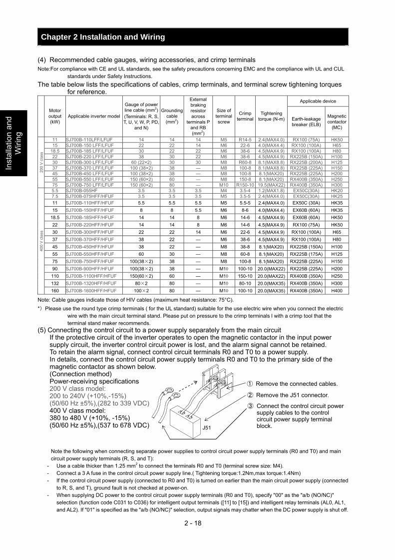
Chapter 2 Installation and Wiring
2 - 18
Inst
alla
tion
and
Wiri
ng
(4) Recommended cable gauges, wiring accessories, and crimp terminals Note:For compliance with CE and UL standards, see the safety precautions concerning EMC and the compliance with UL and CUL
standards under Safety Instructions. The table below lists the specifications of cables, crimp terminals, and terminal screw tightening torques
for reference. Applicable device
Motor output (kW)
Applicable inverter model
Gauge of power line cable (mm2) (Terminals: R, S, T, U, V, W, P, PD,
and N)
Grounding cable (mm2)
External braking resistor across
terminals P and RB (mm2)
Size of terminal screw
Crimp terminal
Tightening torque (N-m) Earth-leakage
breaker (ELB)
Magnetic contactor
(MC)
11 SJ700B-110LFF/LFUF 14 14 14 M5 R14-5 2.4(MAX4.0) RX100 (75A) HK50 15 SJ700B-150 LFF/LFUF 22 22 14 M6 22-6 4.0(MAX4.4) RX100 (100A) H65
18.5 SJ700B-185 LFF/LFUF 30 22 22 M6 38-6 4.5(MAX4.9) RX100 (100A) H80 22 SJ700B-220 LFF/LFUF 38 30 22 M6 38-6 4.5(MAX4.9) RX225B (150A) H100 30 SJ700B-300 LFF/LFUF 60 (22×2) 30 30 M8 R60-8 8.1(MAX8.8) RX225B (200A) H125 37 SJ700B-370 LFF/LFUF 100 (38×2) 38 ― M8 100-8 8.1(MAX8.8) RX225B (225A) H150 45 SJ700B-450 LFF/LFUF 100 (38×2) 38 ― M8 100-8 8.1(MAX20) RX225B (225A) H200 55 SJ700B-550 LFF/LFUF 150 (60×2) 60 ― M8 150-8 8.1(MAX20) RX400B (350A) H250
200
V c
lass
75 SJ700B-750 LFF/LFUF 150 (60×2) 80 ― M10 R150-10 19.5(MAX22) RX400B (350A) H300 5.5 SJ700B-055HF 3.5 3.5 3.5 M4 3.5-4 1.2(MAX1.8) EX50C(30A) HK20 7.5 SJ700B-075HFF/HFUF 3.5 3.5 3.5 M5 3.5-5 2.4(MAX4.0) EX50C(30A) HK25 11 SJ700B-110HFF/HFUF 5.5 5.5 5.5 M5 5.5-5 2.4(MAX4.0) EX50C (30A) HK35 15 SJ700B-150HFF/HFUF 8 8 5.5 M6 8-6 4.0(MAX4.4) EX60B (60A) HK35
18.5 SJ700B-185HFF/HFUF 14 14 8 M6 14-6 4.5(MAX4.9) EX60B (60A) HK50 22 SJ700B-220HFF/HFUF 14 14 8 M6 14-6 4.5(MAX4.9) RX100 (75A) HK50 30 SJ700B-300HFF/HFUF 22 22 14 M6 22-6 4.5(MAX4.9) RX100 (100A) H65 37 SJ700B-370HFF/HFUF 38 22 ― M6 38-6 4.5(MAX4.9) RX100 (100A) H80 45 SJ700B-450HFF/HFUF 38 22 ― M8 38-8 8.1(MAX20) RX225B (150A) H100 55 SJ700B-550HFF/HFUF 60 30 ― M8 60-8 8.1(MAX20) RX225B (175A) H125 75 SJ700B-750HFF/HFUF 100(38×2) 38 ― M8 100-8 8.1(MAX20) RX225B (225A) H150 90 SJ700B-900HFF/HFUF 100(38×2) 38 ― M10 100-10 20.0(MAX22) RX225B (225A) H200 110 SJ700B-1100HFF/HFUF 150(60×2) 60 ― M10 150-10 20.0(MAX22) RX400B (350A) H250 132 SJ700B-1320HFF/HFUF 80×2 80 ― M10 80-10 20.0(MAX35) RX400B (350A) H300
400
V c
lass
160 SJ700B-1600HFF/HFUF 100×2 80 ― M10 100-10 20.0(MAX35) RX400B (350A) H400
Note: Cable gauges indicate those of HIV cables (maximum heat resistance: 75°C). *)Please use the round type crimp terminals ( for the UL standard) suitable for the use electric wire when you connect the electric
wire with the main circuit terminal stand. Please put on pressure to the crimp terminals l with a crimp tool that the terminal stand maker recommends.
(5) Connecting the control circuit to a power supply separately from the main circuit If the protective circuit of the inverter operates to open the magnetic contactor in the input power
supply circuit, the inverter control circuit power is lost, and the alarm signal cannot be retained. To retain the alarm signal, connect control circuit terminals R0 and T0 to a power supply. In details, connect the control circuit power supply terminals R0 and T0 to the primary side of the
magnetic contactor as shown below. (Connection method) Power-receiving specifications 200 V class model: 200 to 240V (+10%,-15%) (50/60 Hz ±5%),(282 to 339 VDC) 400 V class model: 380 to 480 V (+10%, -15%) (50/60 Hz ±5%),(537 to 678 VDC) Note the following when connecting separate power supplies to control circuit power supply terminals (R0 and T0) and main circuit power supply terminals (R, S, and T):
- Use a cable thicker than 1.25 mm2 to connect the terminals R0 and T0 (terminal screw size: M4). - Connect a 3 A fuse in the control circuit power supply line.( Tightening torque:1.2Nm,max torque:1.4Nm) - If the control circuit power supply (connected to R0 and T0) is turned on earlier than the main circuit power supply (connected
to R, S, and T), ground fault is not checked at power-on. - When supplying DC power to the control circuit power supply terminals (R0 and T0), specify "00" as the "a/b (NO/NC)"
selection (function code C031 to C036) for intelligent output terminals ([11] to [15]) and intelligent relay terminals (AL0, AL1, and AL2). If "01" is specified as the "a/b (NO/NC)" selection, output signals may chatter when the DC power supply is shut off.
② Remove the J51 connector.
① Remove the connected cables.
③ Connect the control circuit power supply cables to the control circuit power supply terminal block. J51
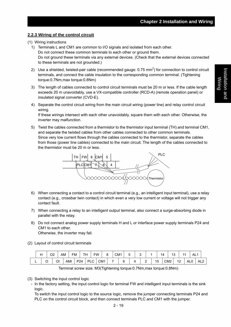
Chapter 2 Installation and Wiring
2 - 19
Installation and W
iring
2.2.3 Wiring of the control circuit (1) Wiring instructions
1) Terminals L and CM1 are common to I/O signals and isolated from each other. Do not connect these common terminals to each other or ground them. Do not ground these terminals via any external devices. (Check that the external devices connected
to these terminals are not grounded.)
2) Use a shielded, twisted-pair cable (recommended gauge: 0.75 mm2) for connection to control circuit terminals, and connect the cable insulation to the corresponding common terminal. (Tightening torque:0.7Nm,max torque:0.8Nm)
3) The length of cables connected to control circuit terminals must be 20 m or less. If the cable length exceeds 20 m unavoidably, use a VX-compatible controller (RCD-A) (remote operation panel) or insulated signal converter (CVD-E).
4) Separate the control circuit wiring from the main circuit wiring (power line) and relay control circuit wiring.
If these wirings intersect with each other unavoidably, square them with each other. Otherwise, the inverter may malfunction.
5) Twist the cables connected from a thermistor to the thermistor input terminal (TH) and terminal CM1, and separate the twisted cables from other cables connected to other common terminals.
Since very low current flows through the cables connected to the thermistor, separate the cables from those (power line cables) connected to the main circuit. The length of the cables connected to the thermistor must be 20 m or less.
6) When connecting a contact to a control circuit terminal (e.g., an intelligent input terminal), use a relay contact (e.g., crossbar twin contact) in which even a very low current or voltage will not trigger any contact fault.
7) When connecting a relay to an intelligent output terminal, also connect a surge-absorbing diode in parallel with the relay.
8) Do not connect analog power supply terminals H and L or interface power supply terminals P24 and CM1 to each other.
Otherwise, the inverter may fail. (2) Layout of control circuit terminals
H O2 AM FM TH FW 8 CM1 5 3 1 14 13 11 AL1
L O OI AMI P24 PLC CM1 7 6 4 2 15 CM2 12 AL0 AL2
Terminal screw size: M3(Tightening torque:0.7Nm,max torque:0.8Nm) (3) Switching the input control logic
- In the factory setting, the input control logic for terminal FW and intelligent input terminals is the sink logic.
To switch the input control logic to the source logic, remove the jumper connecting terminals P24 and PLC on the control circuit block, and then connect terminals PLC and CM1 with the jumper.
TH
PLC CM1 7 6
CM1 8 FW
Thermistor
PLC 5
4
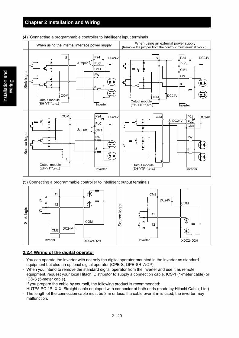
Chapter 2 Installation and Wiring
2 - 20
Inst
alla
tion
and
Wiri
ng
(4) Connecting a programmable controller to intelligent input terminals When using the internal interface power supply When using an external power supply
(Remove the jumper from the control circuit terminal block.)
Sin
k lo
gic
Sou
rce
logi
c
(5) Connecting a programmable controller to intelligent output terminals
Sin
k lo
gic
Sou
rce
logi
c
2.2.4 Wiring of the digital operator - You can operate the inverter with not only the digital operator mounted in the inverter as standard
equipment but also an optional digital operator (OPE-S, OPE-SR,WOP). - When you intend to remove the standard digital operator from the inverter and use it as remote
equipment, request your local Hitachi Distributor to supply a connection cable, ICS-1 (1-meter cable) or ICS-3 (3-meter cable).
If you prepare the cable by yourself, the following product is recommended: HUTP5 PC 4P -X-X: Straight cable equipped with connector at both ends (made by Hitachi Cable, Ltd.) - The length of the connection cable must be 3 m or less. If a cable over 3 m is used, the inverter may
malfunction.
Inverter Output module (EH-YT**,etc.)
Jumper S
COM
P24
PLC
CM1
FW
8
11
12
CM2
COM
Inverter XDC24D2H
DC24V
Inverter
11
XDC24D2H
12
CM2
COM
DC24V
DC24V
PLC
Inverter
P24 DC24V
CM1
FW
DC24V
S
COM Output module(EH-YTP**,etc.)
8
DC24V
Inverter Output module (EH-YT**,etc.)
S
COM P24
PLC
CM1
FW
8
Jumper
Inverter Output module(EH-YTP**,etc.)
DC24VDC24V
COM
S
P24 PLC CM1
FW
8
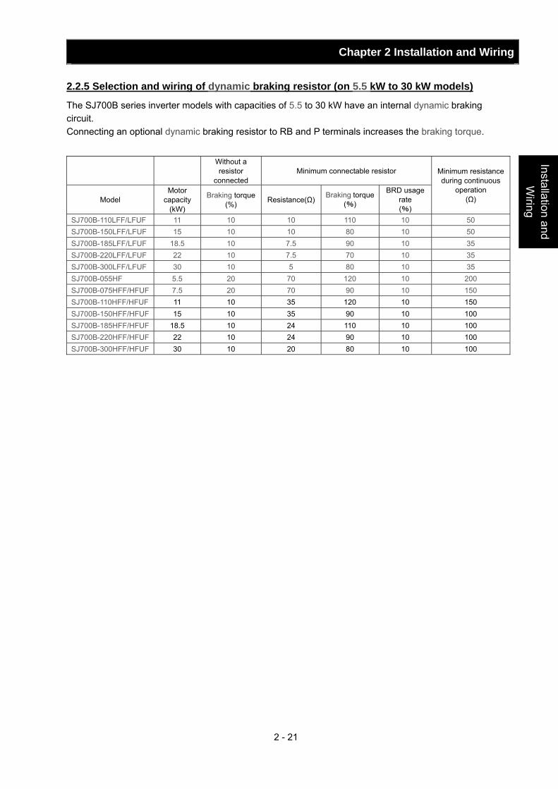
Chapter 2 Installation and Wiring
2 - 21
Installation and W
iring
2.2.5 Selection and wiring of dynamic braking resistor (on 5.5 kW to 30 kW models)
The SJ700B series inverter models with capacities of 5.5 to 30 kW have an internal dynamic braking circuit. Connecting an optional dynamic braking resistor to RB and P terminals increases the braking torque.
Without a resistor
connected Minimum connectable resistor
Model Motor
capacity (kW)
Braking torque (%) Resistance(Ω) Braking torque
(%)
BRD usage rate (%)
Minimum resistance during continuous
operation (Ω)
SJ700B-110LFF/LFUF 11 10 10 110 10 50 SJ700B-150LFF/LFUF 15 10 10 80 10 50 SJ700B-185LFF/LFUF 18.5 10 7.5 90 10 35 SJ700B-220LFF/LFUF 22 10 7.5 70 10 35 SJ700B-300LFF/LFUF 30 10 5 80 10 35 SJ700B-055HF 5.5 20 70 120 10 200 SJ700B-075HFF/HFUF 7.5 20 70 90 10 150 SJ700B-110HFF/HFUF 11 10 35 120 10 150 SJ700B-150HFF/HFUF 15 10 35 90 10 100 SJ700B-185HFF/HFUF 18.5 10 24 110 10 100 SJ700B-220HFF/HFUF 22 10 24 90 10 100 SJ700B-300HFF/HFUF 30 10 20 80 10 100
Chapter 3 Operation This chapter describes typical methods of operating the inverter, how to operate the digital operator, and how to make a test run of the inverter.
3.1 Operating Methods··········································· 3 - 1 3.2 How To Operate the Digital Operator ··············· 3 - 3 3.3 How To Make a Test Run ································· 3 - 10
Operation

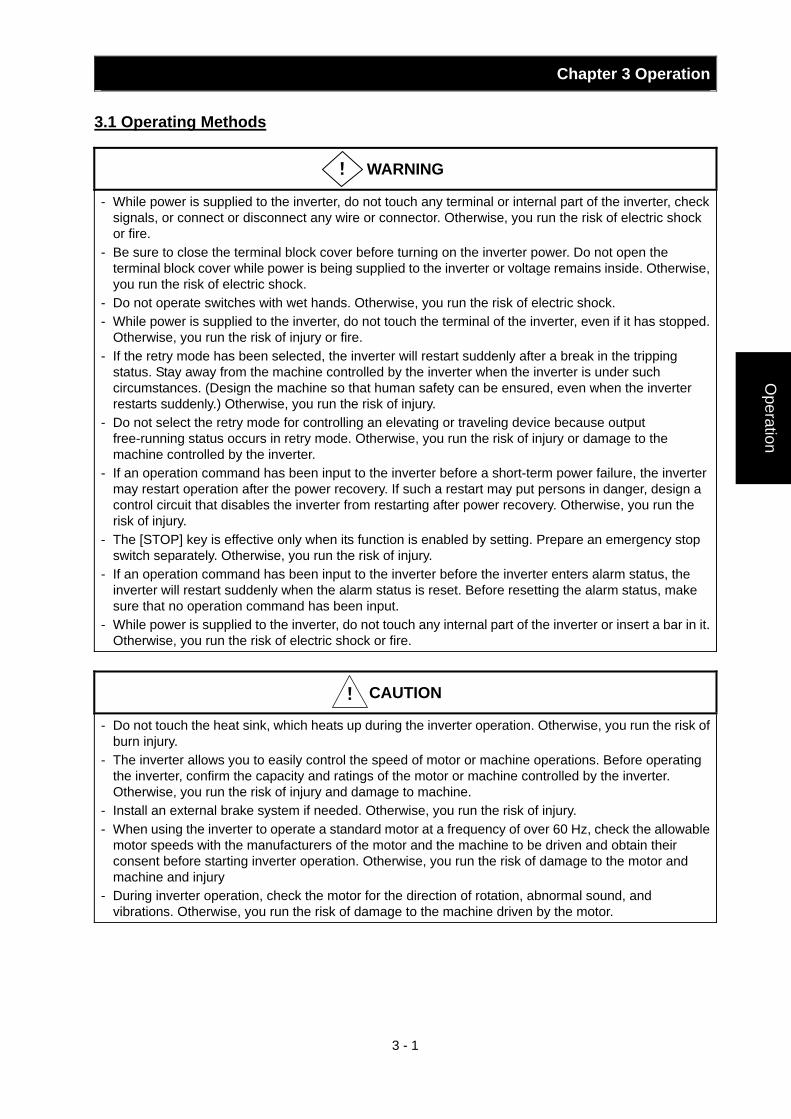
Chapter 3 Operation
3 - 1
Operation
3.1 Operating Methods
WARNING
- While power is supplied to the inverter, do not touch any terminal or internal part of the inverter, check signals, or connect or disconnect any wire or connector. Otherwise, you run the risk of electric shock or fire.
- Be sure to close the terminal block cover before turning on the inverter power. Do not open the terminal block cover while power is being supplied to the inverter or voltage remains inside. Otherwise, you run the risk of electric shock.
- Do not operate switches with wet hands. Otherwise, you run the risk of electric shock. - While power is supplied to the inverter, do not touch the terminal of the inverter, even if it has stopped.
Otherwise, you run the risk of injury or fire. - If the retry mode has been selected, the inverter will restart suddenly after a break in the tripping
status. Stay away from the machine controlled by the inverter when the inverter is under such circumstances. (Design the machine so that human safety can be ensured, even when the inverter restarts suddenly.) Otherwise, you run the risk of injury.
- Do not select the retry mode for controlling an elevating or traveling device because output free-running status occurs in retry mode. Otherwise, you run the risk of injury or damage to the machine controlled by the inverter.
- If an operation command has been input to the inverter before a short-term power failure, the inverter may restart operation after the power recovery. If such a restart may put persons in danger, design a control circuit that disables the inverter from restarting after power recovery. Otherwise, you run the risk of injury.
- The [STOP] key is effective only when its function is enabled by setting. Prepare an emergency stop switch separately. Otherwise, you run the risk of injury.
- If an operation command has been input to the inverter before the inverter enters alarm status, the inverter will restart suddenly when the alarm status is reset. Before resetting the alarm status, make sure that no operation command has been input.
- While power is supplied to the inverter, do not touch any internal part of the inverter or insert a bar in it. Otherwise, you run the risk of electric shock or fire.
CAUTION
- Do not touch the heat sink, which heats up during the inverter operation. Otherwise, you run the risk of burn injury.
- The inverter allows you to easily control the speed of motor or machine operations. Before operating the inverter, confirm the capacity and ratings of the motor or machine controlled by the inverter. Otherwise, you run the risk of injury and damage to machine.
- Install an external brake system if needed. Otherwise, you run the risk of injury. - When using the inverter to operate a standard motor at a frequency of over 60 Hz, check the allowable
motor speeds with the manufacturers of the motor and the machine to be driven and obtain their consent before starting inverter operation. Otherwise, you run the risk of damage to the motor and machine and injury
- During inverter operation, check the motor for the direction of rotation, abnormal sound, and vibrations. Otherwise, you run the risk of damage to the machine driven by the motor.
!
!
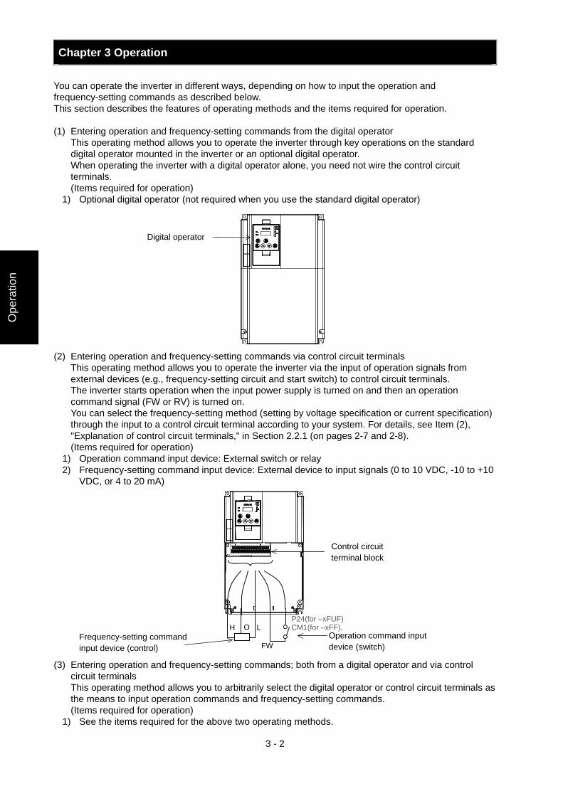
Chapter 3 Operation
3 - 2
Ope
ratio
n
You can operate the inverter in different ways, depending on how to input the operation and frequency-setting commands as described below. This section describes the features of operating methods and the items required for operation. (1) Entering operation and frequency-setting commands from the digital operator This operating method allows you to operate the inverter through key operations on the standard
digital operator mounted in the inverter or an optional digital operator. When operating the inverter with a digital operator alone, you need not wire the control circuit
terminals. (Items required for operation)
1) Optional digital operator (not required when you use the standard digital operator) (2) Entering operation and frequency-setting commands via control circuit terminals This operating method allows you to operate the inverter via the input of operation signals from
external devices (e.g., frequency-setting circuit and start switch) to control circuit terminals. The inverter starts operation when the input power supply is turned on and then an operation
command signal (FW or RV) is turned on. You can select the frequency-setting method (setting by voltage specification or current specification)
through the input to a control circuit terminal according to your system. For details, see Item (2), "Explanation of control circuit terminals," in Section 2.2.1 (on pages 2-7 and 2-8).
(Items required for operation) 1) Operation command input device: External switch or relay 2) Frequency-setting command input device: External device to input signals (0 to 10 VDC, -10 to +10
VDC, or 4 to 20 mA) (3) Entering operation and frequency-setting commands; both from a digital operator and via control
circuit terminals This operating method allows you to arbitrarily select the digital operator or control circuit terminals as
the means to input operation commands and frequency-setting commands. (Items required for operation)
1) See the items required for the above two operating methods.
Digital operator
Operation command input device (switch)
Frequency-setting command input device (control)
Control circuit terminal block
H O LP24(for –xFUF) CM1(for –xFF),
FW
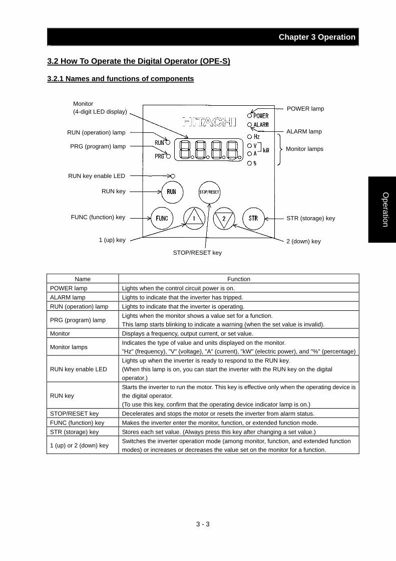
Chapter 3 Operation
3 - 3
Operation
3.2 How To Operate the Digital Operator (OPE-S)
3.2.1 Names and functions of components
Name Function POWER lamp Lights when the control circuit power is on. ALARM lamp Lights to indicate that the inverter has tripped. RUN (operation) lamp Lights to indicate that the inverter is operating.
PRG (program) lamp Lights when the monitor shows a value set for a function. This lamp starts blinking to indicate a warning (when the set value is invalid).
Monitor Displays a frequency, output current, or set value.
Monitor lamps Indicates the type of value and units displayed on the monitor. "Hz" (frequency), "V" (voltage), "A" (current), "kW" (electric power), and "%" (percentage)
RUN key enable LED Lights up when the inverter is ready to respond to the RUN key. (When this lamp is on, you can start the inverter with the RUN key on the digital operator.)
RUN key Starts the inverter to run the motor. This key is effective only when the operating device is the digital operator. (To use this key, confirm that the operating device indicator lamp is on.)
STOP/RESET key Decelerates and stops the motor or resets the inverter from alarm status. FUNC (function) key Makes the inverter enter the monitor, function, or extended function mode. STR (storage) key Stores each set value. (Always press this key after changing a set value.)
1 (up) or 2 (down) key Switches the inverter operation mode (among monitor, function, and extended function modes) or increases or decreases the value set on the monitor for a function.
Monitor lamps
2 (down) key
ALARM lamp
POWER lamp
STR (storage) key
PRG (program) lamp
RUN key enable LED
1 (up) key
RUN (operation) lamp
Monitor (4-digit LED display)
RUN key
FUNC (function) key
STOP/RESET key
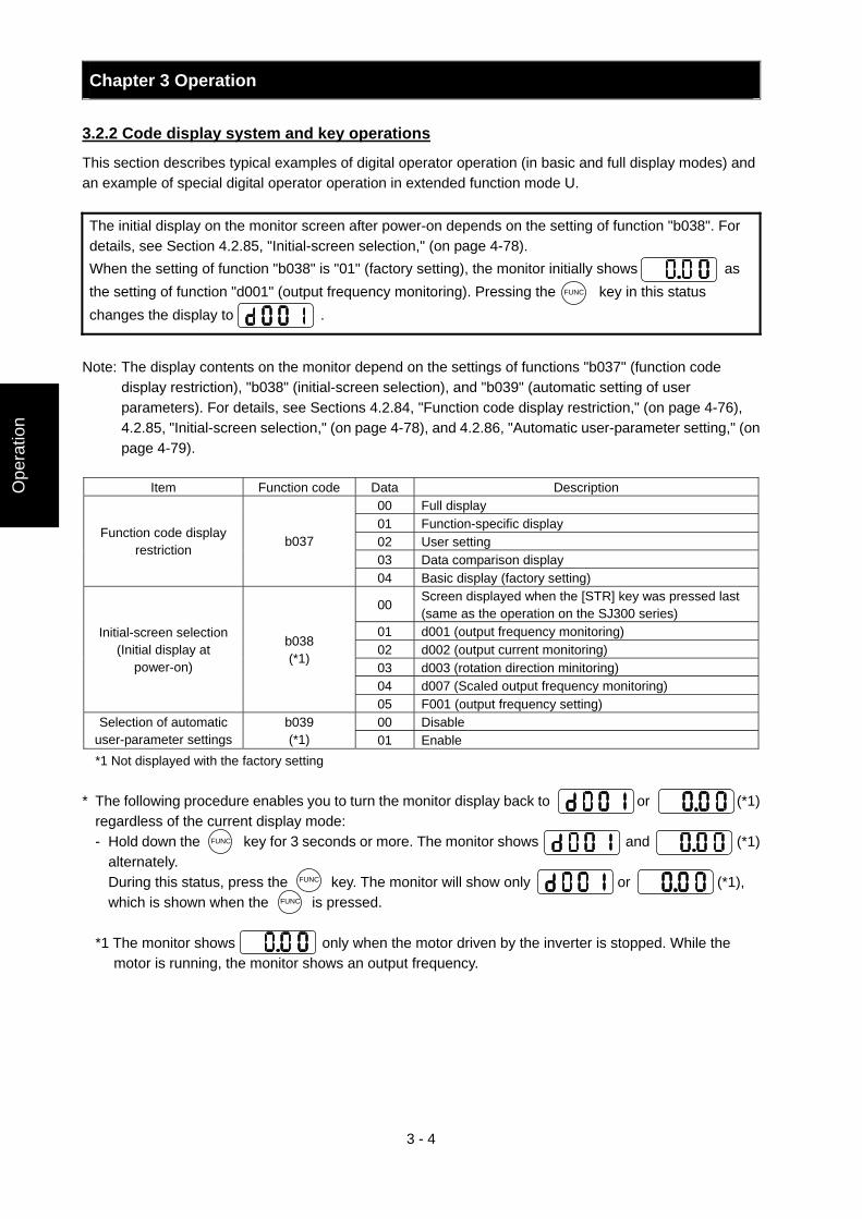
Chapter 3 Operation
3 - 4
Ope
ratio
n
3.2.2 Code display system and key operations
This section describes typical examples of digital operator operation (in basic and full display modes) and an example of special digital operator operation in extended function mode U. The initial display on the monitor screen after power-on depends on the setting of function "b038". For details, see Section 4.2.85, "Initial-screen selection," (on page 4-78). When the setting of function "b038" is "01" (factory setting), the monitor initially shows as the setting of function "d001" (output frequency monitoring). Pressing the key in this status changes the display to .
Note: The display contents on the monitor depend on the settings of functions "b037" (function code
display restriction), "b038" (initial-screen selection), and "b039" (automatic setting of user parameters). For details, see Sections 4.2.84, "Function code display restriction," (on page 4-76), 4.2.85, "Initial-screen selection," (on page 4-78), and 4.2.86, "Automatic user-parameter setting," (on page 4-79).
Item Function code Data Description
00 Full display 01 Function-specific display 02 User setting 03 Data comparison display
Function code display restriction
b037
04 Basic display (factory setting)
00 Screen displayed when the [STR] key was pressed last (same as the operation on the SJ300 series)
01 d001 (output frequency monitoring) 02 d002 (output current monitoring) 03 d003 (rotation direction minitoring) 04 d007 (Scaled output frequency monitoring)
Initial-screen selection (Initial display at
power-on)
b038 (*1)
05 F001 (output frequency setting) 00 Disable Selection of automatic
user-parameter settings b039 (*1) 01 Enable
*1 Not displayed with the factory setting * The following procedure enables you to turn the monitor display back to or (*1)
regardless of the current display mode: - Hold down the key for 3 seconds or more. The monitor shows and (*1)
alternately. During this status, press the key. The monitor will show only or (*1),
which is shown when the is pressed.
*1 The monitor shows only when the motor driven by the inverter is stopped. While the motor is running, the monitor shows an output frequency.
FUNC
FUNC
FUNC
FUNC
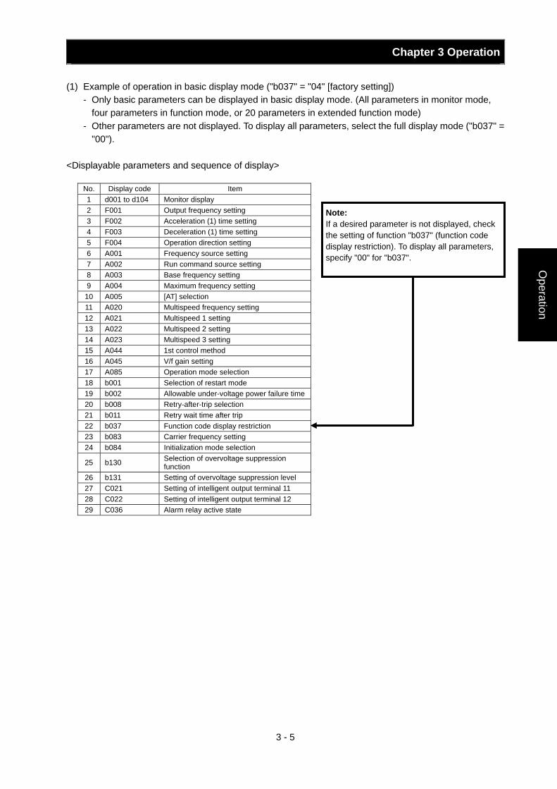
Chapter 3 Operation
3 - 5
Operation
(1) Example of operation in basic display mode ("b037" = "04" [factory setting]) - Only basic parameters can be displayed in basic display mode. (All parameters in monitor mode,
four parameters in function mode, or 20 parameters in extended function mode) - Other parameters are not displayed. To display all parameters, select the full display mode ("b037" =
"00"). <Displayable parameters and sequence of display>
Note: If a desired parameter is not displayed, check the setting of function "b037" (function code display restriction). To display all parameters, specify "00" for "b037".
No. Display code Item 1 d001 to d104 Monitor display 2 F001 Output frequency setting 3 F002 Acceleration (1) time setting 4 F003 Deceleration (1) time setting 5 F004 Operation direction setting 6 A001 Frequency source setting 7 A002 Run command source setting 8 A003 Base frequency setting 9 A004 Maximum frequency setting
10 A005 [AT] selection 11 A020 Multispeed frequency setting 12 A021 Multispeed 1 setting 13 A022 Multispeed 2 setting 14 A023 Multispeed 3 setting 15 A044 1st control method 16 A045 V/f gain setting 17 A085 Operation mode selection 18 b001 Selection of restart mode 19 b002 Allowable under-voltage power failure time20 b008 Retry-after-trip selection 21 b011 Retry wait time after trip 22 b037 Function code display restriction 23 b083 Carrier frequency setting 24 b084 Initialization mode selection
25 b130 Selection of overvoltage suppression function
26 b131 Setting of overvoltage suppression level 27 C021 Setting of intelligent output terminal 11 28 C022 Setting of intelligent output terminal 12 29 C036 Alarm relay active state
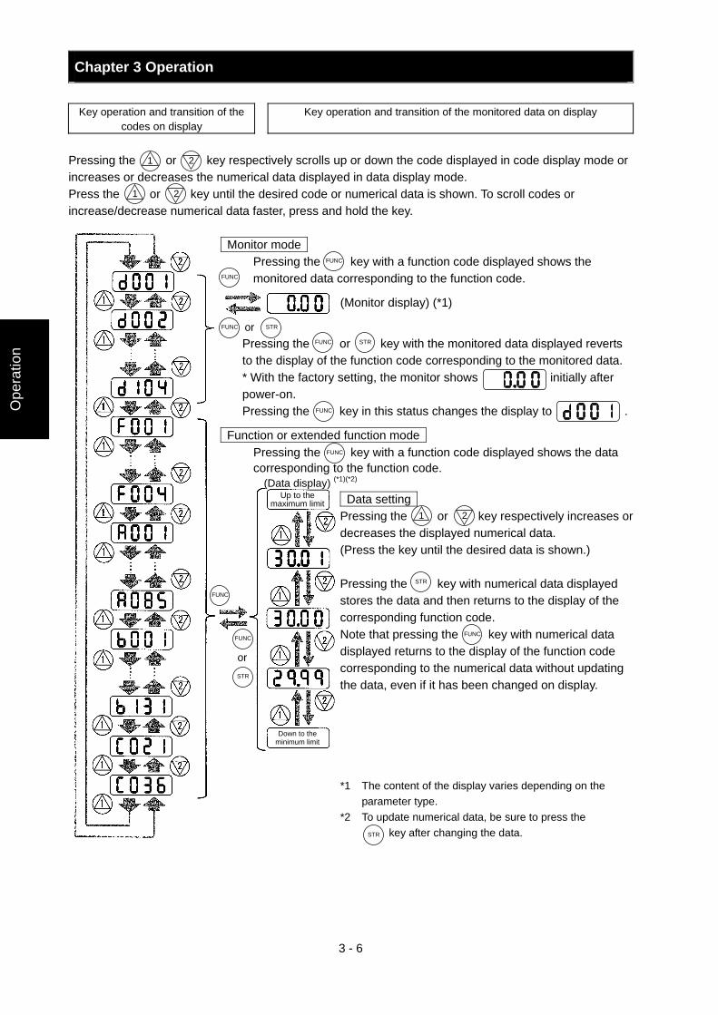
Chapter 3 Operation
3 - 6
Ope
ratio
n
Key operation and transition of the
codes on display Key operation and transition of the monitored data on display
Pressing the or key respectively scrolls up or down the code displayed in code display mode or increases or decreases the numerical data displayed in data display mode. Press the or key until the desired code or numerical data is shown. To scroll codes or increase/decrease numerical data faster, press and hold the key.
Monitor mode Pressing the key with a function code displayed shows the monitored data corresponding to the function code.
(Monitor display) (*1)
Pressing the or key with the monitored data displayed reverts to the display of the function code corresponding to the monitored data. * With the factory setting, the monitor shows initially after power-on. Pressing the key in this status changes the display to .
Function or extended function mode Pressing the key with a function code displayed shows the data corresponding to the function code.
(Data display) (*1)(*2) Data setting Pressing the or key respectively increases or decreases the displayed numerical data. (Press the key until the desired data is shown.) Pressing the key with numerical data displayed stores the data and then returns to the display of the corresponding function code. Note that pressing the key with numerical data displayed returns to the display of the function code corresponding to the numerical data without updating the data, even if it has been changed on display.
*1 The content of the display varies depending on the parameter type.
*2 To update numerical data, be sure to press the key after changing the data.
1 2
1 2
or
Up to the maximum limit
Down to the minimum limit
1 2
or
FUNC
FUNC
FUNC
STR
FUNC STR
FUNC
FUNC
STR
FUNC
FUNC
STR
STR
FUNC
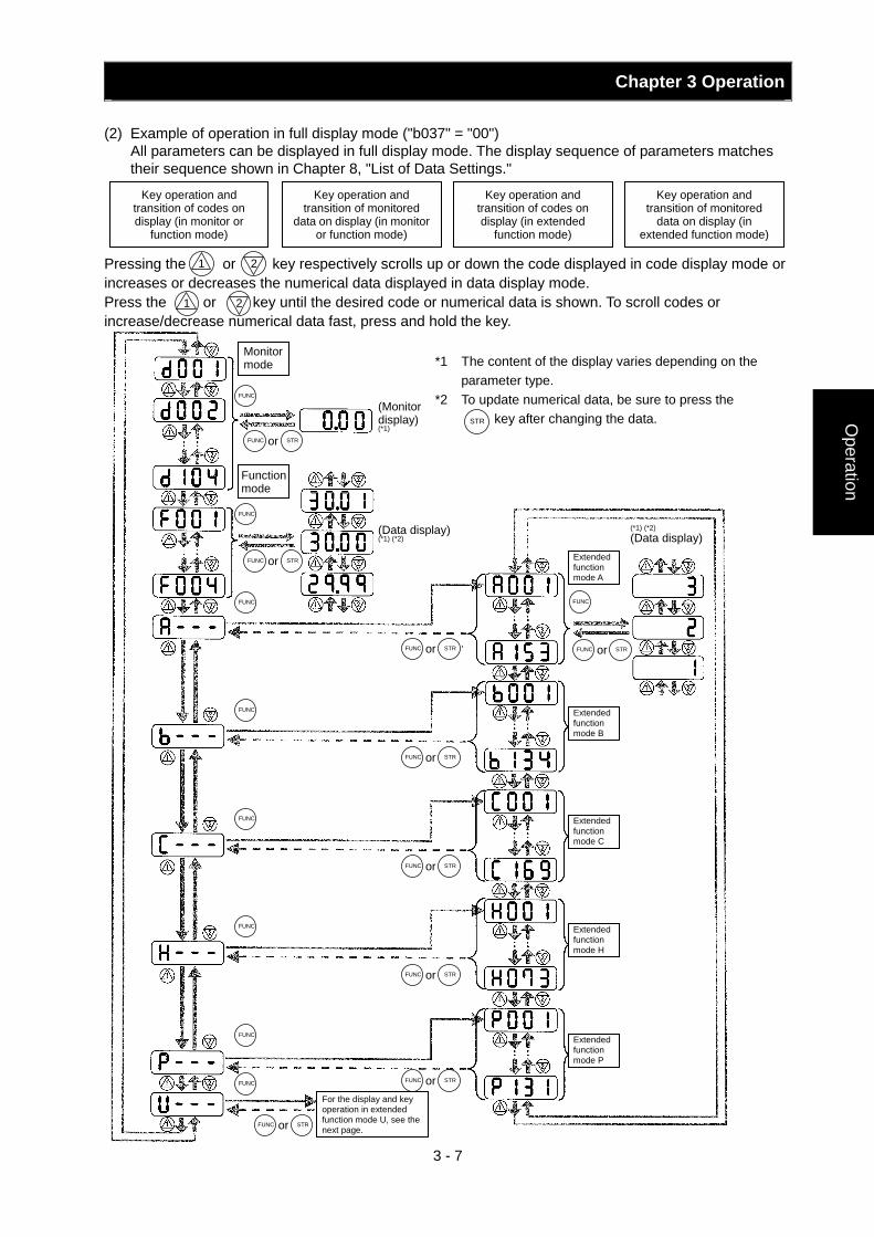
Chapter 3 Operation
3 - 7
Operation
(2) Example of operation in full display mode ("b037" = "00") All parameters can be displayed in full display mode. The display sequence of parameters matches
their sequence shown in Chapter 8, "List of Data Settings." Pressing the or key respectively scrolls up or down the code displayed in code display mode or increases or decreases the numerical data displayed in data display mode. Press the or key until the desired code or numerical data is shown. To scroll codes or increase/decrease numerical data fast, press and hold the key.
*1 The content of the display varies depending on the parameter type.
*2 To update numerical data, be sure to press the key after changing the data.
Key operation and transition of codes on display (in monitor or
function mode)
Key operation and transition of monitored
data on display (in monitor or function mode)
Key operation and transition of codes on display (in extended
function mode)
Key operation and transition of monitored
data on display (in extended function mode)
1 2
1 2
FUNC
Monitor mode
(Monitor display) (*1)
(Data display) (*1) (*2)
Function mode
or FUNC STR
FUNC
FUNC
FUNC
FUNC
FUNC
or FUNC STR
or FUNC STR
or FUNC STR
or FUNC STR
or FUNC STR
or FUNC STR
or FUNC STR
FUNC
Extended function mode A
For the display and key operation in extended function mode U, see the next page.
(*1) (*2) (Data display)
Extended function mode B
Extended function mode C
Extended function mode H
Extended function mode P
or FUNC STR
FUNC
STR
FUNC
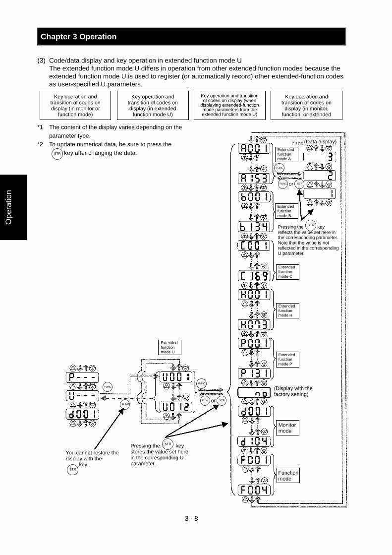
Chapter 3 Operation
3 - 8
Ope
ratio
n
(3) Code/data display and key operation in extended function mode U The extended function mode U differs in operation from other extended function modes because the
extended function mode U is used to register (or automatically record) other extended-function codes as user-specified U parameters.
*1 The content of the display varies depending on the
parameter type. *2 To update numerical data, be sure to press the
key after changing the data.
Key operation and transition of codes on display (in monitor or
function mode)
Key operation and transition of codes on display (in extended
function mode U)
Key operation and transition of codes on display (when
displaying extended-function mode parameters from the extended function mode U)
Key operation and transition of codes on
display (in monitor, function, or extended
STR
(*1) (*2) (Data display) Extended function mode A
Extended function mode B
Extended function mode C
Extended function mode H
Extended function mode P
Monitor mode
Function mode
Pressing the key reflects the value set here in the corresponding parameter. Note that the value is not reflected in the corresponding U parameter.
Extended function mode U
Pressing the key stores the value set here in the corresponding U parameter.
You cannot restore the display with the key.
(Display with the factory setting)
FUNC
or FUNC STR
FUNC
or FUNC STR
FUNC
FUNC
STR
STR
STR
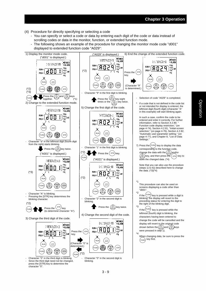
Chapter 3 Operation
3 - 9
Operation
(4) Procedure for directly specifying or selecting a code
- You can specify or select a code or data by entering each digit of the code or data instead of scrolling codes or data in the monitor, function, or extended function mode.
- The following shows an example of the procedure for changing the monitor mode code "d001" displayed to extended function code "A029":
("A029" is displayed.)
FUNC STR
RUN STOP/ RESET
FUNC STR
RUN STOP/ RESET
FUNC
RUN STOP/ RESET
FUNC STR
RUN STOP/ RESET
STR
FUNC
RUN STOP/ RESET
STR
FUNC STR
RUN STOP/ RESET
FUNC
RUN STOP/ RESET
STR
FUNC STR
RUN STOP/ RESET
FUNC STR
RUN STOP/ RESET
FUNC
STR
FUNC
FUNC
STR
FUNC
(*2) (*3)
2) Change to the extended function mode.
Press the and keys together. (*1)
1
- Character "d" in the leftmost digit (fourth digit from the right) starts blinking.
2
Press the key twice. 2
("A001" is displayed.)
(*3)
- Character "A" is blinking. - Pressing the [STR] key determines the
blinking character.
(*2)
Press the key (to determine character "A").
3) Change the third digit of the code.
- Character "0" in the third digit is blinking. - Since the third digit need not be changed,
press the [STR] key to determine the character "0".
- Character "0" in the second digit is blinking.
Press the key.
(Character "0" is determined.)
(*2)
4) Change the second digit of the code.
Press the key twice. 1
- Character "2" in the second digit is blinking.
(*2)
(*2)
- Character "1" in the first digit is blinking.
STRPress the key.
("A021" is displayed.)
5) Change the first digit of the code.
- Character "9" in the first digit is blinking.
Press the key eight times or the key twice.
1
2
(*2) STRPress the key.
(Character "9" is determined.)
- Selection of code "A029" is completed. * If a code that is not defined in the code list
or not intended for display is entered, the leftmost digit (fourth digit) (character "A" in this example) will start blinking again.
In such a case, confirm the code to be entered and enter it correctly. For further information, refer to Section 4.2.80. " Function code display restriction," (on page 4-74), Section 4.2.81, "Initial-screen selection," (on page 4-76), Section 4.2.82, "Automatic user-parameter setting," (on page 4-77), and Chapter 8, "List of Data Settings."
7) Press the key to display the data
corresponding to the function code, change the data with the and/or key, and then press the key to store the changed data. (*4)
Note that you can also use the procedure (steps 1) to 6)) described here to change the data. (*3)(*4)
*1
This procedure can also be used on screens displaying a code other than "d001".
*2 If the key is pressed while a digit is blinking, the display will revert to the preceding status for entering the digit to the right of the blinking digit.
*3 If the key is pressed while the leftmost (fourth) digit is blinking, the characters having been entered to change the code will be cancelled and the display will revert to the original code shown before the and keys were pressed in step 1).
*4 When changing data, be sure to press the key first.
FUNC
1 2
FUNC
FUNC
FUNC
1 2
STR
("d001" is displayed.) 1) Display the monitor mode code. 6) End the change of the extended function code.
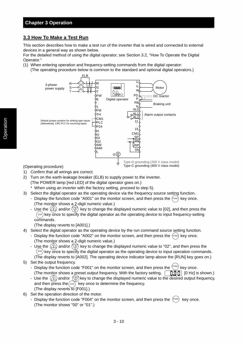
Chapter 3 Operation
3 - 10
Ope
ratio
n
3.3 How To Make a Test Run This section describes how to make a test run of the inverter that is wired and connected to external devices in a general way as shown below. For the detailed method of using the digital operator, see Section 3.2, "How To Operate the Digital Operator." (1) When entering operation and frequency-setting commands from the digital operator: (The operating procedure below is common to the standard and optional digital operators.) (Operating procedure) 1) Confirm that all wirings are correct. 2) Turn on the earth-leakage breaker (ELB) to supply power to the inverter. (The POWER lamp [red LED] of the digital operator goes on.)
* When using an inverter with the factory setting, proceed to step 5). 3) Select the digital operator as the operating device via the frequency source setting function.
- Display the function code "A001" on the monitor screen, and then press the key once. (The monitor shows a 2-digit numeric value.) - Use the and/or key to change the displayed numeric value to [02], and then press the
key once to specify the digital operator as the operating device to input frequency-setting commands.
(The display reverts to [A001].) 4) Select the digital operator as the operating device by the run command source setting function.
- Display the function code "A002" on the monitor screen, and then press the key once. (The monitor shows a 2-digit numeric value.) - Use the and/or key to change the displayed numeric value to "02", and then press the
key once to specify the digital operator as the operating device to input operation commands. (The display reverts to [A002]. The operating device indicator lamp above the [RUN] key goes on.)
5) Set the output frequency. - Display the function code "F001" on the monitor screen, and then press the key once. (The monitor shows a preset output frequency. With the factory setting, [0 Hz] is shown.) - Use the and/or key to change the displayed numeric value to the desired output frequency,
and then press the key once to determine the frequency. (The display reverts to [F001].)
6) Set the operation direction of the motor. - Display the function code "F004" on the monitor screen, and then press the key once. (The monitor shows "00" or "01".)
G
Type-D grounding (200 V class model) Type-C grounding (400 V class model)
DC reactor
Motor
UVW
PDP
RBN
AL0AL1AL211
CM215
SPSNRPSN
Braking unit
Alarm output contacts
AMI AM
L
O2 OI O H P24 PLC CM1 TH FM 1
8 FW
R S T
RST
3-phase power supply
ELB
...
Digital operator
...
FUNC
FUNC
STR
STR
1 2
FUNC
1 2 STR
1 2
FUNC
Default jumper position for sinking type inputs (Altanatively, CM1-PLC for souricing tiype)
Chapter 3 Operation
3 - 11
Operation
- Use the and/or key to change the displayed value to "00" for forward operation or "01" for reverse operation, and then press the key once to determine the operation direction.
(The display reverts to [F004].) 7) Set the monitor mode.
- To monitor the output frequency, display the function code "d001", and then press the key once. (The monitor shows the output frequency.) To monitor the operation direction, display the function code "d003", and then press the key
once. (The monitor shows for forward operation, for reverse operation, or for stopping.)
8) Press the key to start the motor. (The RUN lamp [green LED] goes on.) 9) Press the key to decelerate or stop the motor. (When the motor stops, the RUN lamp [green LED] goes off.) - During the test run, confirm that the inverter does not trip while accelerating or decelerating the motor
and that the motor speed and frequencies are correct. - If a trip due to overcurrent or overvoltage has occurred during the test run, increase the acceleration
and deceleration time. - Make sure that there is enough margin to trip level by monitoring the output current (d002) and DC
voltage (d102).
STR
1 2
FUNC
FUNC
RUN
STOP/ RESET
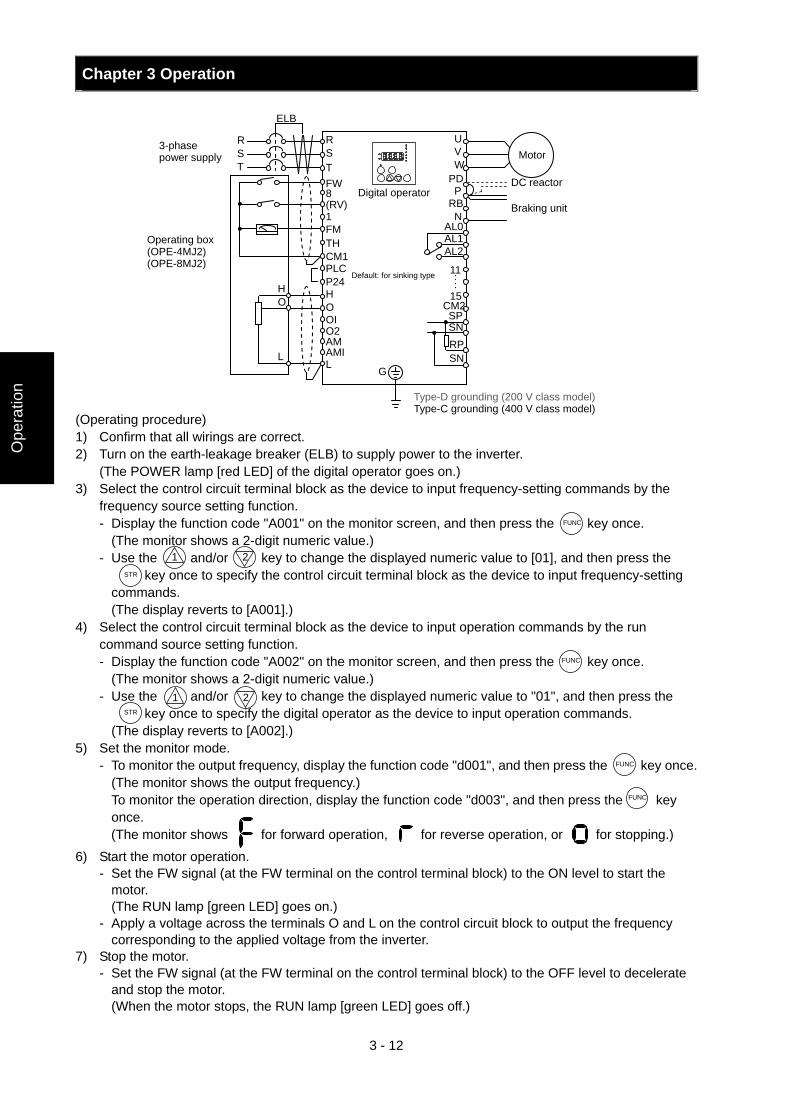
Chapter 3 Operation
3 - 12
Ope
ratio
n
(Operating procedure) 1) Confirm that all wirings are correct. 2) Turn on the earth-leakage breaker (ELB) to supply power to the inverter. (The POWER lamp [red LED] of the digital operator goes on.) 3) Select the control circuit terminal block as the device to input frequency-setting commands by the
frequency source setting function. - Display the function code "A001" on the monitor screen, and then press the key once.
(The monitor shows a 2-digit numeric value.) - Use the and/or key to change the displayed numeric value to [01], and then press the
key once to specify the control circuit terminal block as the device to input frequency-setting commands.
(The display reverts to [A001].) 4) Select the control circuit terminal block as the device to input operation commands by the run
command source setting function. - Display the function code "A002" on the monitor screen, and then press the key once.
(The monitor shows a 2-digit numeric value.) - Use the and/or key to change the displayed numeric value to "01", and then press the
key once to specify the digital operator as the device to input operation commands. (The display reverts to [A002].)
5) Set the monitor mode. - To monitor the output frequency, display the function code "d001", and then press the key once. (The monitor shows the output frequency.) To monitor the operation direction, display the function code "d003", and then press the key
once. (The monitor shows for forward operation, for reverse operation, or for stopping.)
6) Start the motor operation. - Set the FW signal (at the FW terminal on the control terminal block) to the ON level to start the
motor. (The RUN lamp [green LED] goes on.)
- Apply a voltage across the terminals O and L on the control circuit block to output the frequency corresponding to the applied voltage from the inverter.
7) Stop the motor. - Set the FW signal (at the FW terminal on the control terminal block) to the OFF level to decelerate
and stop the motor. (When the motor stops, the RUN lamp [green LED] goes off.)
UVW
PDP
RBN
AL0AL1AL2
11 ・・・・
CM215
SPSNRPSN
G
H
L
O H
Operating box (OPE-4MJ2) (OPE-8MJ2)
AMI AM
L
O2 OI O
P24 PLC CM1 TH FM1
8 FW
RST
RST
ELB
(RV)
Type-D grounding (200 V class model) Type-C grounding (400 V class model)
DC reactor
Motor
Braking unit
3-phase power supply
Digital operator
FUNC
1 2
FUNC
1 2
STR
STR
FUNC
FUNC
Default: for sinking type
Chapter 4 Explanation of Functions This chapter describes the functions of the inverter.
4.1 Monitor Mode ··················································· 4 - 1 4.2 Function Mode·················································· 4 - 7 4.3 Functions Available When the Feedback
Option Board (SJ-FB) Is Mounted···················· 4 - 96 4.4 Communication Functions································ 4 - 113
Explanation of Functions

Chapter 4 Explanation of Functions
4 - 1
Explanation of Functions
4.1 Monitor Mode
4.1.1 Output frequency monitoring When the output frequency monitoring function (d001) is selected, the inverter displays the output frequency. The inverter displays "0.00" when the frequency output is stopped. The Hz monitor lamp lights up while the inverter is displaying the output frequency.
(Display) 0.00 to 99.99 in steps of 0.01 Hz 100.0 to 400.0 in steps of 0.1 Hz
Note: When you have selected the digital operator as the device to input frequency-setting commands (A001=02), you can change the output frequency setting by using the and/or key (only while the inverter is operating the motor). - The change in output frequency made in this mode can be reflected in the frequency setting
(function "F001"). Press the STR key to write the new frequency over the currently selected frequency setting.
- You cannot change the output frequency while the PID function is enabled or the inverter is not operating the motor.
4.1.2 Output current monitoring When the output current monitoring function (d002) is selected, the inverter displays the output current. The inverter displays "0.0" when the current output is stopped. The A monitor lamp lights up while the inverter is displaying the output current.
(Display) 0.0 to 999.9 in steps of 0.1 A
4.1.3 Rotation direction monitoring When the rotation direction monitoring function (d003) is selected, the inverter displays the motor operation direction. The RUN lamp lights up while the inverter is operating the motor (in forward or reverse direction).
(Display) F: Forward operation o: Motor stopped r: Reverse operation
4.1.4 Process variable (PV), PID feedback monitoring When "01" (enabling PID operation) or "02" (enabling inverted-data output) has been specified for function "A071" (PID Function Enable) and the process variable (PV), PID feedback monitoring function (d004) is selected, the inverter displays the PID feedback data. You can also convert the PID feedback to gain data by setting a PV scale conversion (with function "A075").
Value displayed by function "d004" = "feedback quantity" (%) x " PV scale conversion (A075)" The PV scale conversion can be set (by function "A075") within the range 0.01 to 99.99 in steps of 0.01.
(Display) 0.00 to 99.99 in steps of 0.01 100.0 to 999.9 in steps of 0.1 1000. to 9999. in steps of 1 ⎡100 to ⎡999 in units of 10
d001: Output frequency monitoring Related code
d002: Output current monitoring Related code
d003: Rotation direction monitoring Related code
d004: Process variable (PV), PID feedback monitoring A071: PID Function Enable A075: PV scale conversion
Related code
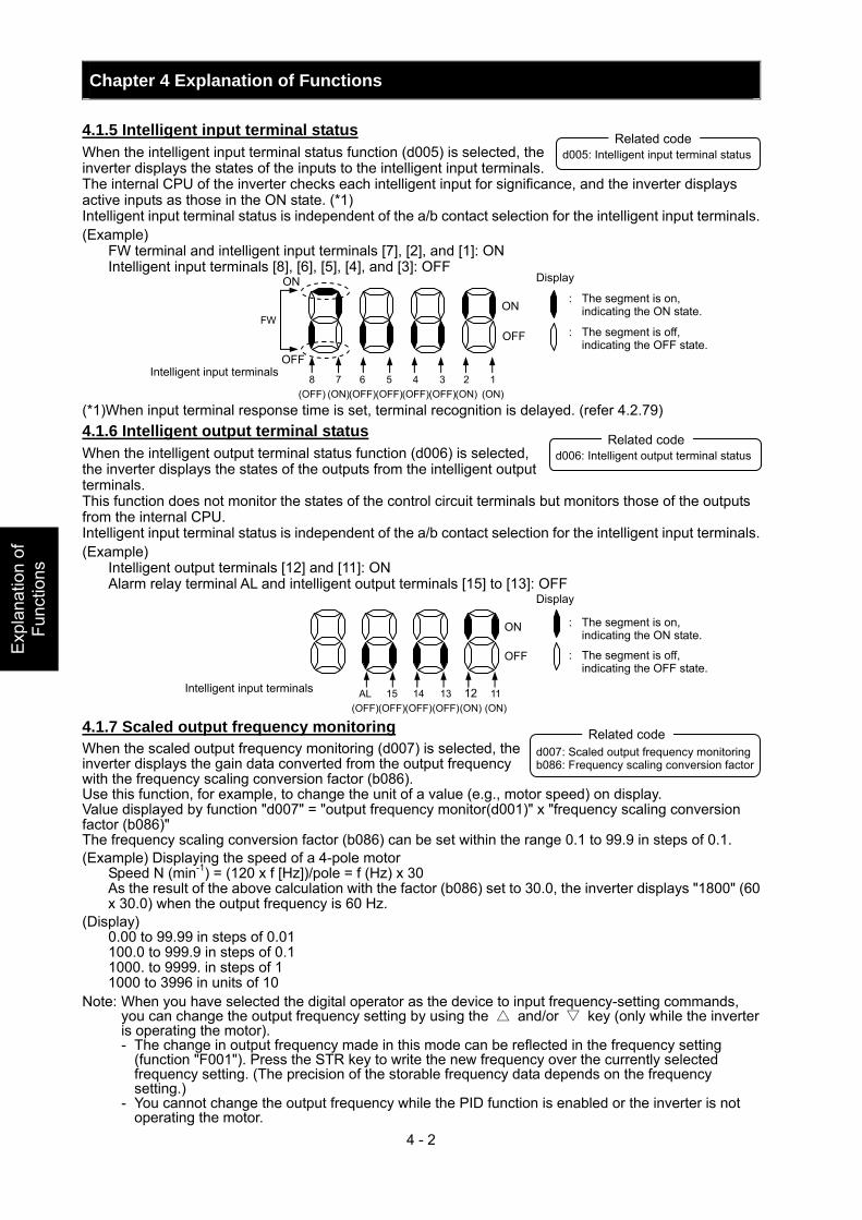
Chapter 4 Explanation of Functions
4 - 2
Exp
lana
tion
of
Func
tions
4.1.5 Intelligent input terminal status When the intelligent input terminal status function (d005) is selected, the inverter displays the states of the inputs to the intelligent input terminals. The internal CPU of the inverter checks each intelligent input for significance, and the inverter displays active inputs as those in the ON state. (*1) Intelligent input terminal status is independent of the a/b contact selection for the intelligent input terminals. (Example)
FW terminal and intelligent input terminals [7], [2], and [1]: ON Intelligent input terminals [8], [6], [5], [4], and [3]: OFF
(*1)When input terminal response time is set, terminal recognition is delayed. (refer 4.2.79) 4.1.6 Intelligent output terminal status When the intelligent output terminal status function (d006) is selected, the inverter displays the states of the outputs from the intelligent output terminals. This function does not monitor the states of the control circuit terminals but monitors those of the outputs from the internal CPU. Intelligent input terminal status is independent of the a/b contact selection for the intelligent input terminals. (Example)
Intelligent output terminals [12] and [11]: ON Alarm relay terminal AL and intelligent output terminals [15] to [13]: OFF
4.1.7 Scaled output frequency monitoring When the scaled output frequency monitoring (d007) is selected, the inverter displays the gain data converted from the output frequency with the frequency scaling conversion factor (b086). Use this function, for example, to change the unit of a value (e.g., motor speed) on display. Value displayed by function "d007" = "output frequency monitor(d001)" x "frequency scaling conversion factor (b086)" The frequency scaling conversion factor (b086) can be set within the range 0.1 to 99.9 in steps of 0.1. (Example) Displaying the speed of a 4-pole motor
Speed N (min-1) = (120 x f [Hz])/pole = f (Hz) x 30 As the result of the above calculation with the factor (b086) set to 30.0, the inverter displays "1800" (60 x 30.0) when the output frequency is 60 Hz.
(Display) 0.00 to 99.99 in steps of 0.01 100.0 to 999.9 in steps of 0.1 1000. to 9999. in steps of 1 1000 to 3996 in units of 10
Note: When you have selected the digital operator as the device to input frequency-setting commands, you can change the output frequency setting by using the and/or key (only while the inverter is operating the motor). - The change in output frequency made in this mode can be reflected in the frequency setting
(function "F001"). Press the STR key to write the new frequency over the currently selected frequency setting. (The precision of the storable frequency data depends on the frequency setting.)
- You cannot change the output frequency while the PID function is enabled or the inverter is not operating the motor.
ON
ON
OFFFW
OFF
1 (ON)
2 (ON)
3 (OFF)
4 (OFF)
5 (OFF)
6 (OFF)
7 (ON)
8 (OFF)
Display
: The segment is on, indicating the ON state.
: The segment is off, indicating the OFF state.
Intelligent input terminals
ON
OFF
11 (ON)
12 (ON)
13 (OFF)
14 (OFF)
15 (OFF)
AL (OFF)
Display
: The segment is on, indicating the ON state.
: The segment is off, indicating the OFF state.
Intelligent input terminals
d005: Intelligent input terminal status Related code
d006: Intelligent output terminal status Related code
d007: Scaled output frequency monitoring b086: Frequency scaling conversion factor
Related code
Chapter 4 Explanation of Functions
4 - 3
Explanation of Functions
4.1.8 Actual-frequency monitoring The actual-frequency monitoring function is effective only when a motor equipped with an encoder is connected to the inverter and the feedback option board (SJ-FB) is mounted in the inverter. When the actual-frequency monitoring function (d008) is selected, the inverter displays the actual operating frequency of the motor (regardless of the motor control method (A044 or A244)). (Display)
Forward operation: 0.00 to 99.99 in steps of 0.01 Hz 100.0 to 400.0 in steps of 0.1 Hz
Reverse operation: - 0.0 to -99.9 in steps of 0.1 Hz - 100 to -400 in steps of 1 Hz
Note: To use this monitoring function, set the encoder pulse-per-revolution (PPR) setting (P011) and the number of motor poles (H004 or H204) correctly.
4.1.9 Torque command monitoring The torque command monitoring function is effective when you have selected control by torque for the vector control with sensor. When the torque command monitoring function (d009) is selected, the inverter displays the value of the currently input torque command. The % monitor lamp lights up while the inverter is displaying the torque command value. Assign 52 (ATR) on intelligent input terminal and turn on to activate torque control. (Display)
-200. to +200. in steps of 1 % 4.1.10 Torque bias monitoring The torque bias monitoring function is effective when you have selected the vector control with sensor. When the torque bias monitoring function (d010) is selected, the inverter displays the value of the currently set value of torque bias. The % monitor lamp lights up while the inverter is displaying the torque bias value. (Display)
-200. to +200. in steps of 1 % 4.1.11 Torque monitoring When the torque monitoring function (d012) is selected, the inverter displays the estimated value of the torque output from the inverter. The % monitor lamp lights up while the inverter is displaying the estimated output torque. (Display)
-200. to +200. in steps of 1 % Note: This monitoring function is effective only when you have selected the sensorless vector control,
0Hz-range sensorless vector control, or vector control with sensor as the control mode. Displayed value is not accurate when the other control method is selected. 4.1.12 Output voltage monitoring When the output voltage monitoring function (d013) is selected, the inverter displays the voltage output from the inverter. The V monitor lamp lights up while the inverter is displaying the output voltage. (Display)
0.0 to 600.0 in steps of 0.1 V (remark) Displayed value may not be accurate when the output voltage is differ from input voltage. 4.1.13 Power monitoring When the power monitoring function (d014) is selected, the inverter displays the electric power (momentary value) input to the inverter. The kW monitor lamps (V and A lamps) light up while the inverter is displaying the input power. (Display)
0.0 to 999.9 in steps of 0.1 kW
d008: Actual-frequency monitoring P011: Encoder pulse-per-revolution (PPR) setting H004: Motor poles setting, 1st motor H204: Motor poles setting, 2nd motor
Related code
d009: Torque command monitoring P033: Torque command input selectionP034: Torque command setting A044: V/f characteristic curve selectcion C001 to C008: Terminal [1] to [8]
Related code
d013: Output voltage monitoring Related code
d014: Power monitoring Related code
d010: Torque bias monitoring A044: V/f characteristic curve selectcion P036: Torque bias mode P037: Torque bias value P038: Torque bias polarity
Related code
Related code d012: Torque monitoring A044: V/f characteristic curve selectcion
Chapter 4 Explanation of Functions
4 - 4
Exp
lana
tion
of
Func
tions
4.1.14 Cumulative power monitoring When the cumulative power monitoring function is selected, the inverter displays the cumulative value of electric power input to the inverter. You can also convert the value to be displayed to gain data by setting the cumulative input power display gain setting (b079).
Value displayed by function "d015" = "calculated value of input power (kW/h)"/"cumulative input power display gain setting (b079)" The cumulative power input gain can be set within the range 1 to 1000 in steps of 1.
You can clear the cumulative power data by specifying "01" for the cumulative power clearance function (b078) and pressing the STR key. You can also clear the cumulative power data at an intelligent input terminal by assigning function "53" (KHC: cumulative power clearance) to the intelligent input terminal. When the cumulative input power display gain setting (b079) is set to "1000", the cumulative power data up to 999000 (kW/h) can be displayed.
(Display) 0.0 to 999.9 in steps of 1 kW/h, or the unit set for function "b079" 1000 to 9999 in units of 10 kW/h, or the unit set for function "b079" ⎡100 to ⎡999 in units of 1000 kW/h, or the unit set for function "b079"
4.1.15 Cumulative operation RUN time monitoring When the cumulative operation RUN time monitoring function (d016) is selected, the inverter displays the cumulative time of the inverter operation.
(Display) 0. to 9999. in units of 1 hour 1000 to 9999 in units of 10 hours ⎡100 to ⎡999 in units of 1,000 hours
4.1.16 Cumulative power-on time monitoring When the cumulative power-on time monitoring function(d017) is selected, the inverter displays the cumulative time throughout which the inverter power has been on.
(Display) 0. to 9999. in units of 1 hour 1000 to 9999 in units of 10 hours ⎡100 to ⎡999 in units of 1,000 hours
4.1.17 Heat sink temperature monitoring When the heat sink temperature monitoring function (d018) is selected, the inverter displays the temperature of the internal heat sink of the inverter. (Display)
0.0 to 200.0 in steps of 0.1 °C 4.1.18 Motor temperature monitoring When the motor temperature monitoring function is selected, the inverter displays the temperature of the thermistor connected between control circuit terminals TH and CM1. Use the thermistor model PB-41E made by Shibaura Electronics Corporation. Specify "02" (enabling NTC) for the thermistor for thermal protection control (function "b098").
(Display) 0.0 to 200.0 in steps of 0.1 °C.
Note: If "01" (enabling PTC) is specified for the thermistor for thermal protection control (function "b098"), motor temperature monitoring is disabled.
d015: Cumulative power monitoring b078: Cumulative power clearance b079: Cumulative input power display gain setting
Related code
d016: Cumulative operation RUN time monitoring
Related code
d017: Cumulative power-on time monitoring
Related code
d019: Motor temperature monitoring b098: Thermistor for thermal
protection control
Related code
d018: Heat sink temperature monitoring
Related code
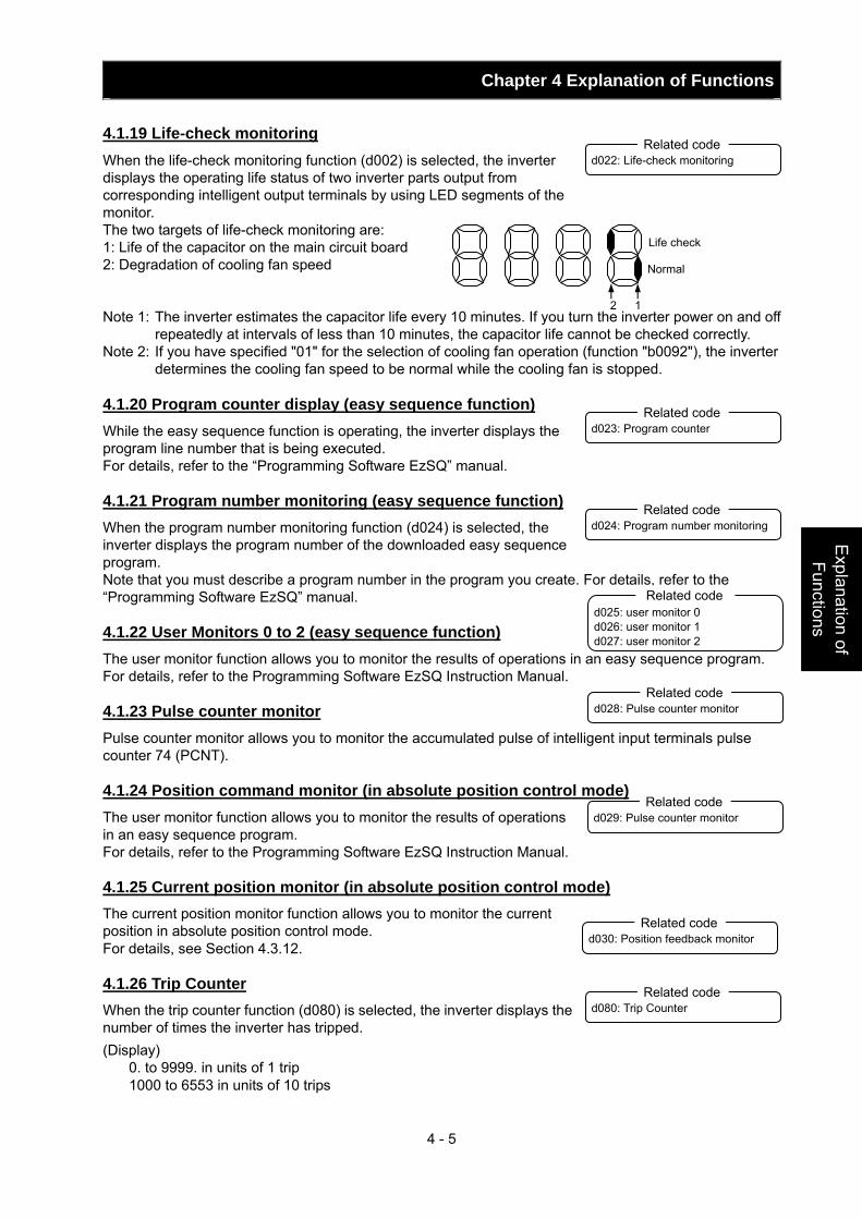
Chapter 4 Explanation of Functions
4 - 5
Explanation of Functions
4.1.19 Life-check monitoring When the life-check monitoring function (d002) is selected, the inverter displays the operating life status of two inverter parts output from corresponding intelligent output terminals by using LED segments of the monitor. The two targets of life-check monitoring are: 1: Life of the capacitor on the main circuit board 2: Degradation of cooling fan speed Note 1: The inverter estimates the capacitor life every 10 minutes. If you turn the inverter power on and off
repeatedly at intervals of less than 10 minutes, the capacitor life cannot be checked correctly. Note 2: If you have specified "01" for the selection of cooling fan operation (function "b0092"), the inverter
determines the cooling fan speed to be normal while the cooling fan is stopped. 4.1.20 Program counter display (easy sequence function) While the easy sequence function is operating, the inverter displays the program line number that is being executed. For details, refer to the “Programming Software EzSQ” manual. 4.1.21 Program number monitoring (easy sequence function) When the program number monitoring function (d024) is selected, the inverter displays the program number of the downloaded easy sequence program. Note that you must describe a program number in the program you create. For details, refer to the “Programming Software EzSQ” manual. 4.1.22 User Monitors 0 to 2 (easy sequence function) The user monitor function allows you to monitor the results of operations in an easy sequence program. For details, refer to the Programming Software EzSQ Instruction Manual. 4.1.23 Pulse counter monitor Pulse counter monitor allows you to monitor the accumulated pulse of intelligent input terminals pulse counter 74 (PCNT). 4.1.24 Position command monitor (in absolute position control mode) The user monitor function allows you to monitor the results of operations in an easy sequence program. For details, refer to the Programming Software EzSQ Instruction Manual. 4.1.25 Current position monitor (in absolute position control mode) The current position monitor function allows you to monitor the current position in absolute position control mode. For details, see Section 4.3.12. 4.1.26 Trip Counter When the trip counter function (d080) is selected, the inverter displays the number of times the inverter has tripped. (Display)
0. to 9999. in units of 1 trip 1000 to 6553 in units of 10 trips
d022: Life-check monitoring Related code
1 2
Life check
Normal
d023: Program counter Related code
d024: Program number monitoring Related code
d080: Trip Counter Related code
d028: Pulse counter monitor Related code
d029: Pulse counter monitor Related code
d025: user monitor 0 d026: user monitor 1 d027: user monitor 2
Related code
d030: Position feedback monitor Related code
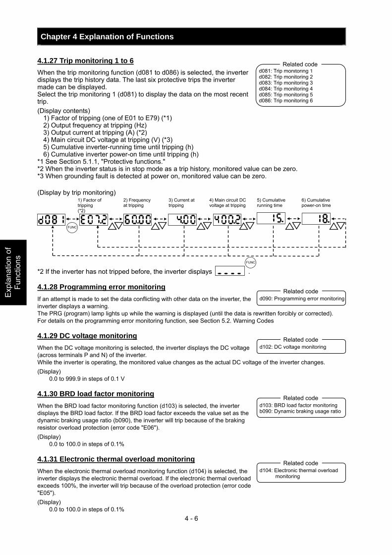
Chapter 4 Explanation of Functions
4 - 6
Exp
lana
tion
of
Func
tions
4.1.27 Trip monitoring 1 to 6 When the trip monitoring function (d081 to d086) is selected, the inverter displays the trip history data. The last six protective trips the inverter made can be displayed. Select the trip monitoring 1 (d081) to display the data on the most recent trip. (Display contents)
1) Factor of tripping (one of E01 to E79) (*1) 2) Output frequency at tripping (Hz) 3) Output current at tripping (A) (*2) 4) Main circuit DC voltage at tripping (V) (*3) 5) Cumulative inverter-running time until tripping (h) 6) Cumulative inverter power-on time until tripping (h)
*1 See Section 5.1.1, "Protective functions." *2 When the inverter status is in stop mode as a trip history, monitored value can be zero. *3 When grounding fault is detected at power on, monitored value can be zero. (Display by trip monitoring) *2 If the inverter has not tripped before, the inverter displays . 4.1.28 Programming error monitoring If an attempt is made to set the data conflicting with other data on the inverter, the inverter displays a warning. The PRG (program) lamp lights up while the warning is displayed (until the data is rewritten forcibly or corrected). For details on the programming error monitoring function, see Section 5.2. Warning Codes 4.1.29 DC voltage monitoring When the DC voltage monitoring is selected, the inverter displays the DC voltage (across terminals P and N) of the inverter. While the inverter is operating, the monitored value changes as the actual DC voltage of the inverter changes. (Display)
0.0 to 999.9 in steps of 0.1 V 4.1.30 BRD load factor monitoring When the BRD load factor monitoring function (d103) is selected, the inverter displays the BRD load factor. If the BRD load factor exceeds the value set as the dynamic braking usage ratio (b090), the inverter will trip because of the braking resistor overload protection (error code "E06"). (Display)
0.0 to 100.0 in steps of 0.1% 4.1.31 Electronic thermal overload monitoring When the electronic thermal overload monitoring function (d104) is selected, the inverter displays the electronic thermal overload. If the electronic thermal overload exceeds 100%, the inverter will trip because of the overload protection (error code "E05"). (Display)
0.0 to 100.0 in steps of 0.1%
d081: Trip monitoring 1 d082: Trip monitoring 2 d083: Trip monitoring 3 d084: Trip monitoring 4 d085: Trip monitoring 5 d086: Trip monitoring 6
Related code
1) Factor of tripping (*2)
2) Frequency at tripping
3) Current at tripping
4) Main circuit DC voltage at tripping
5) Cumulative running time
6) Cumulative power-on time
FUNC
FUNC
d090: Programming error monitoring Related code
d102: DC voltage monitoring Related code
d103: BRD load factor monitoring b090: Dynamic braking usage ratio
Related code
d104: Electronic thermal overload monitoring
Related code
Chapter 4 Explanation of Functions
4 - 7
Explanation of Functions
4.2 Function Mode
4.2.1 Output frequency setting The output frequency setting function allows you to set the inverter output frequency. You can set the inverter output frequency with this function (F001) only when you have specified "02" for the frequency source setting (A001). For other methods of frequency setting, see Section 4.2.4, "frequency source setting (A001)." (If the setting of function "A001" is other than "02", function "F001" operates as the frequency command monitoring function.) The frequency set with function "F001" is automatically set as the Multispeed frequency setting (A020). To set the second and third multispeed s, use the multispeed frequency setting, 2nd motor, function (A220) and multispeed frequency setting, 3rd motor, function (A320), or use function "F001" for the setting after turning on the SET and SET3 signals. For the setting using the SET and SET3 signals, assign the SET function (08) and SET3 function (17) to intelligent input terminals. If the set output frequency is used as the target data for the PID function, PID feedback data will be displayed in percent (%). ("100%" indicates the maximum frequency.)
Item Function code Range of data Description Output frequency setting F001
Multispeed 0 A020/A220/ A320
0.0, start frequency to maximum frequency, 1st/2nd/3rd motors
(Hz)
The frequency set with F001 is equal to the setting of A020. The second control frequency set with F001 is equal to the setting of A220. The third control frequency set with F001 is equal to the setting of A320.
4.2.2 Keypad Run key routing When you enter operation commands via the digital operator, the Keypad Run key routing function allows you to select the direction of motor operation. This function is ineffective when you use the control terminal block or remote operator to input operation commands.
Item Function code Data Description 00 Forward operation Keypad Run key routing F004 01 Reverse operation
4.2.3 Rotational direction restriction The rotational direction restriction function allows you to restrict the direction of motor operation. This function is effective regardless of the specification of operation command input device (e.g., control circuit block or digital operator). If an operation command to drive the motor in a restricted direction is input, the inverter (digital operator) will display .
Item Function code Data Description 00 Both forward and reverse operations are enabled.01 Only forward operation is enabled. Rotational direction
restriction b035 02 Only reverse operation is enabled.
F001: Output frequency setting A001: Frequency source setting A020/A220/A320:
Multispeed frequency setting, 1st/2nd/3rd motors
C001 to C008: Terminal [1] to [8] functions
Related code
F004: Keypad Run key routing
b035: Rotational direction restriction Related code
Related code
Chapter 4 Explanation of Functions
4 - 8
Exp
lana
tion
of
Func
tions
4.2.4 Frequency source setting The frequency source setting function allows you to select the method to input the frequency-setting command.
Motor rotation direction is inverted when -10 to 0V is given as frequency command to 02-L terminals.
Item Function code Data Description
(00) (Valid only when the OPE-SR is used) Use the control provided on the digital operator to set the frequency.
01 Input the frequency-setting command via a control circuit terminal (0-L, OI-L, or O2-L).
02 Use the digital operator (function "F001") or remote operator to set the frequency.
03 Input the frequency-setting command via an RS485 communication terminal.
04 Input the frequency-setting command from the board connected to optional port 1.
05 Input the frequency-setting command from the board connected to optional port 2.
06 Use the SJ-FB to input the frequency-setting command as a pulse train(see 4.2.21)
07 Use the SET-Freq command of the easy sequence function as the frequency-setting command.
Frequency source setting
A001
10 Use the operation result of the set frequency operation function as the frequency-setting command. (see 4.2.12)
4.2.5 Run command source setting The run command source setting function allows you to select the method to input operation commands (to start and stop the motor). As the operation commands via control circuit terminals, turn the FW signal (for forward operation) or RV signal (for reverse operation) on and off to start and stop the motor, respectively. (Note that the factory setting assigns the FW signal to intelligent input terminal [8].) To switch each intelligent input terminal between a and b contacts, specify each terminal with function "C011" to "C019", and then perform input a/b (NO/NC) selection for each terminal. When using the digital operation for the inverter operation, specify the desired motor operation direction with function "F004", and use the RUN and STOP/RESET keys to start and stop the motor, respectively. If the start commands for both forward and reverse operations are input at the same time, the inverter will assume the input of a stop command.
Item Function code Data Description
01 Input the start and stop commands via control circuit terminals (FW and RV).
02 Input the start and stop commands from the digital or remote operator.
03 Input the start and stop commands via RS485 communication terminals.
04 Input the start and stop commands from option board 1.
Run command source setting A002
05 Input the start and stop commands from option board 2. 00 a (NO) contact Terminal [FW]
active state C019
C011 to C018 01 b (NC) contact
Note 1: If function "31" (forcible operation) or "51" (forcible-operation terminal) is assigned to an intelligent input terminal, the settings made with functions "A001" and "A002" will be invalidated when the said intelligent input terminal is turned on and those methods to input frequency-setting and operation commands which are specified for the said terminal will be enabled.
Note 2: On the remote operator (SRW) being used to operate the inverter, pressing the REMT (remote) key enables you to input both frequency-setting and operation commands from the remote operator.
Note3: When the DeviceNet option board (SJ-DN) is used, A002 is not needed to be changed from default because the run command source is automatically set via DeviceNet. (In case it is changed, it is to be set as 01, 02 or 03.)
A001: Frequency source setting Related code
A002: Run command source setting C011 to C018: Terminal [1] to [8] functions C019: Terminal [FW] active state F004: Keypad Run key routing
Related code
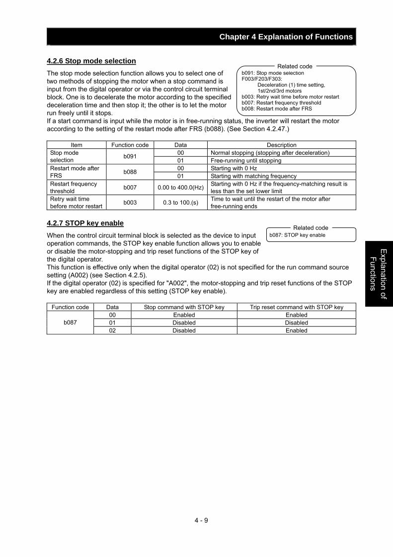
Chapter 4 Explanation of Functions
4 - 9
Explanation of Functions
4.2.6 Stop mode selection The stop mode selection function allows you to select one of two methods of stopping the motor when a stop command is input from the digital operator or via the control circuit terminal block. One is to decelerate the motor according to the specified deceleration time and then stop it; the other is to let the motor run freely until it stops. If a start command is input while the motor is in free-running status, the inverter will restart the motor according to the setting of the restart mode after FRS (b088). (See Section 4.2.47.)
Item Function code Data Description 00 Normal stopping (stopping after deceleration) Stop mode
selection b091 01 Free-running until stopping 00 Starting with 0 Hz Restart mode after
FRS b088 01 Starting with matching frequency
Restart frequency threshold b007 0.00 to 400.0(Hz) Starting with 0 Hz if the frequency-matching result is
less than the set lower limit Retry wait time before motor restart b003 0.3 to 100.(s) Time to wait until the restart of the motor after
free-running ends 4.2.7 STOP key enable When the control circuit terminal block is selected as the device to input operation commands, the STOP key enable function allows you to enable or disable the motor-stopping and trip reset functions of the STOP key of the digital operator. This function is effective only when the digital operator (02) is not specified for the run command source setting (A002) (see Section 4.2.5). If the digital operator (02) is specified for "A002", the motor-stopping and trip reset functions of the STOP key are enabled regardless of this setting (STOP key enable).
Function code Data Stop command with STOP key Trip reset command with STOP key 00 Enabled Enabled 01 Disabled Disabled b087 02 Disabled Enabled
b091: Stop mode selection F003/F203/F303:
Deceleration (1) time setting, 1st/2nd/3rd motors
b003: Retry wait time before motor restart b007: Restart frequency threshold b008: Restart mode after FRS
Related code
b087: STOP key enable Related code
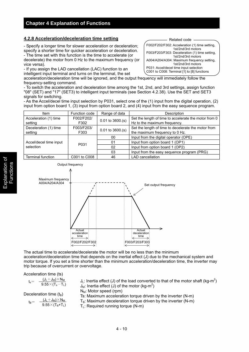
Chapter 4 Explanation of Functions
4 - 10
Exp
lana
tion
of
Func
tions
4.2.8 Acceleration/deceleration time setting - Specify a longer time for slower acceleration or deceleration; specify a shorter time for quicker acceleration or deceleration. - The time set with this function is the time to accelerate (or decelerate) the motor from 0 Hz to the maximum frequency (or vice versa). - If you assign the LAD cancellation (LAC) function to an intelligent input terminal and turns on the terminal, the set acceleration/deceleration time will be ignored, and the output frequency will immediately follow the frequency-setting command. - To switch the acceleration and deceleration time among the 1st, 2nd, and 3rd settings, assign function "08" (SET) and "17" (SET3) to intelligent input terminals (see Section 4.2.38). Use the SET and SET3 signals for switching. - As the Accel/decel time input selection by P031, select one of the (1) input from the digital operation, (2) input from option board 1, (3) input from option board 2, and (4) input from the easy sequence program.
Item Function code Range of data Description Acceleration (1) time setting
F002/F202/ F302 0.01 to 3600.(s) Set the length of time to accelerate the motor from 0
Hz to the maximum frequency. Deceleration (1) time setting
F003/F203/ F303 0.01 to 3600.(s) Set the length of time to decelerate the motor from
the maximum frequency to 0 Hz. 00 Input from the digital operator (OPE) 01 Input from option board 1 (OP1) 02 Input from option board 1 (OP2)
Accel/decel time input selection P031
03 Input from the easy sequence program (PRG) Terminal function C001 to C008 46 LAD cancellation
The actual time to accelerate/decelerate the motor will be no less than the minimum acceleration/deceleration time that depends on the inertial effect (J) due to the mechanical system and motor torque. If you set a time shorter than the minimum acceleration/deceleration time, the inverter may trip because of overcurrent or overvoltage.
JL: Inertia effect (J) of the load converted to that of the motor shaft (kg-m2) JM: Inertia effect (J) of the motor (kg-m2) NM: Motor speed (rpm) Ts: Maximum acceleration torque driven by the inverter (N-m) TB: Maximum deceleration torque driven by the inverter (N-m) TL: Required running torque (N-m)
F002/F202/F302: Acceleration (1) time setting, 1st/2nd/3rd motors
F003/F203/F303: Deceleration (1) time setting, 1st/2nd/3rd motors
A004/A204/A304: Maximum frequency setting, 1st/2nd/3rd motors
P031: Accel/decel time input selection C001 to C008: Terminal [1] to [8] functions
Related code
Maximum frequency A004/A204/A304
F002/F202/F302 F003/F203/F303
Output frequency
Set output frequency
Actual acceleration
time
Actual deceleration
time
Acceleration time (ts) Deceleration time (tB)
ts= (JL+JM)×NM 9.55×(Ts-TL)
tB= (JL+JM)×NM 9.55×(TB+TL)
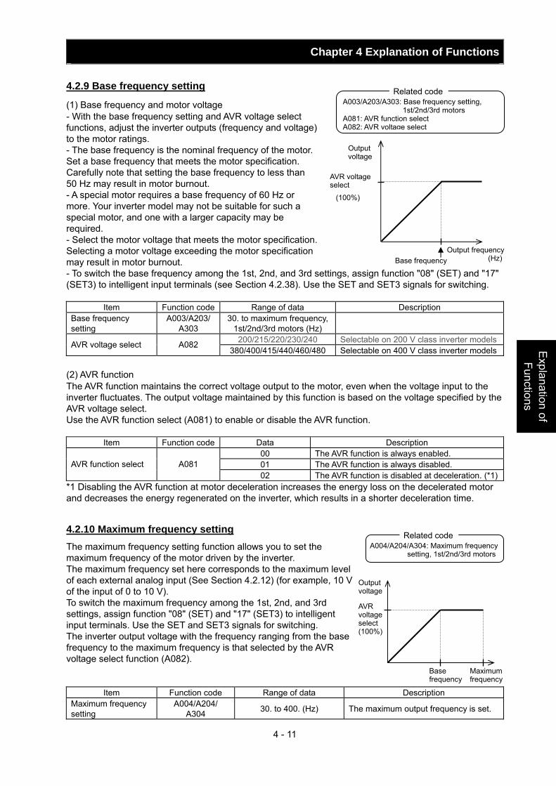
Chapter 4 Explanation of Functions
4 - 11
Explanation of Functions
4.2.9 Base frequency setting
(1) Base frequency and motor voltage - With the base frequency setting and AVR voltage select functions, adjust the inverter outputs (frequency and voltage) to the motor ratings. - The base frequency is the nominal frequency of the motor. Set a base frequency that meets the motor specification. Carefully note that setting the base frequency to less than 50 Hz may result in motor burnout. - A special motor requires a base frequency of 60 Hz or more. Your inverter model may not be suitable for such a special motor, and one with a larger capacity may be required. - Select the motor voltage that meets the motor specification. Selecting a motor voltage exceeding the motor specification may result in motor burnout. - To switch the base frequency among the 1st, 2nd, and 3rd settings, assign function "08" (SET) and "17" (SET3) to intelligent input terminals (see Section 4.2.38). Use the SET and SET3 signals for switching.
Item Function code Range of data Description Base frequency setting
A003/A203/ A303
30. to maximum frequency, 1st/2nd/3rd motors (Hz)
200/215/220/230/240 Selectable on 200 V class inverter modelsAVR voltage select A082 380/400/415/440/460/480 Selectable on 400 V class inverter models
(2) AVR function The AVR function maintains the correct voltage output to the motor, even when the voltage input to the inverter fluctuates. The output voltage maintained by this function is based on the voltage specified by the AVR voltage select. Use the AVR function select (A081) to enable or disable the AVR function.
Item Function code Data Description 00 The AVR function is always enabled. 01 The AVR function is always disabled. AVR function select A081 02 The AVR function is disabled at deceleration. (*1)
*1 Disabling the AVR function at motor deceleration increases the energy loss on the decelerated motor and decreases the energy regenerated on the inverter, which results in a shorter deceleration time.
4.2.10 Maximum frequency setting The maximum frequency setting function allows you to set the maximum frequency of the motor driven by the inverter. The maximum frequency set here corresponds to the maximum level of each external analog input (See Section 4.2.12) (for example, 10 V of the input of 0 to 10 V). To switch the maximum frequency among the 1st, 2nd, and 3rd settings, assign function "08" (SET) and "17" (SET3) to intelligent input terminals. Use the SET and SET3 signals for switching. The inverter output voltage with the frequency ranging from the base frequency to the maximum frequency is that selected by the AVR voltage select function (A082).
Item Function code Range of data Description Maximum frequency setting
A004/A204/ A304 30. to 400. (Hz) The maximum output frequency is set.
Base frequency Output frequency
(Hz)
A003/A203/A303: Base frequency setting, 1st/2nd/3rd motors
A081: AVR function select A082: AVR voltage select
Related code
Output voltage
AVR voltage select
A004/A204/A304: Maximum frequency setting, 1st/2nd/3rd motors
Related code
Output voltage
AVR voltage select (100%)
Base frequency
Maximum frequency
(100%)
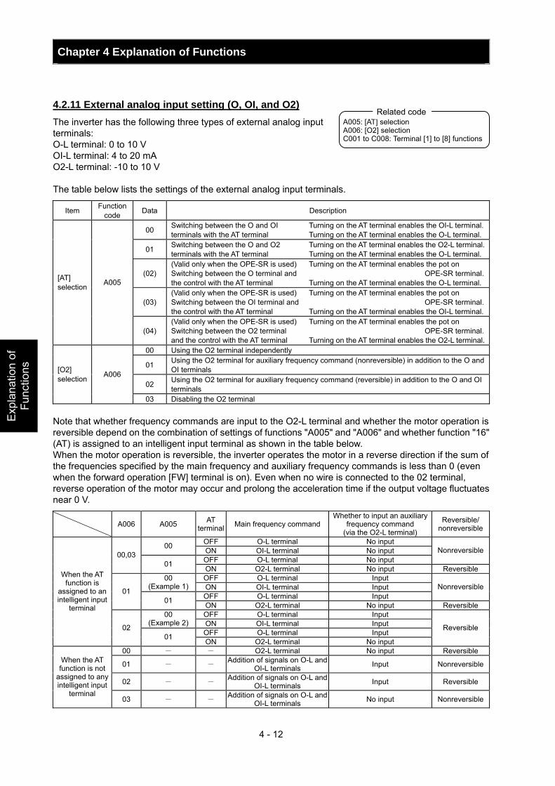
Chapter 4 Explanation of Functions
4 - 12
Exp
lana
tion
of
Func
tions
4.2.11 External analog input setting (O, OI, and O2) The inverter has the following three types of external analog input terminals: O-L terminal: 0 to 10 V OI-L terminal: 4 to 20 mA O2-L terminal: -10 to 10 V The table below lists the settings of the external analog input terminals.
Item Function code Data Description
00 Switching between the O and OI terminals with the AT terminal
Turning on the AT terminal enables the OI-L terminal.Turning on the AT terminal enables the O-L terminal.
01 Switching between the O and O2 terminals with the AT terminal
Turning on the AT terminal enables the O2-L terminal.Turning on the AT terminal enables the O-L terminal.
(02) (Valid only when the OPE-SR is used)Switching between the O terminal and the control with the AT terminal
Turning on the AT terminal enables the pot on OPE-SR terminal.
Turning on the AT terminal enables the O-L terminal.
(03) (Valid only when the OPE-SR is used)Switching between the OI terminal and the control with the AT terminal
Turning on the AT terminal enables the pot on OPE-SR terminal.
Turning on the AT terminal enables the OI-L terminal.
[AT] selection A005
(04) (Valid only when the OPE-SR is used)Switching between the O2 terminal and the control with the AT terminal
Turning on the AT terminal enables the pot on OPE-SR terminal.
Turning on the AT terminal enables the O2-L terminal.00 Using the O2 terminal independently
01 Using the O2 terminal for auxiliary frequency command (nonreversible) in addition to the O and OI terminals
02 Using the O2 terminal for auxiliary frequency command (reversible) in addition to the O and OI terminals
[O2] selection A006
03 Disabling the O2 terminal Note that whether frequency commands are input to the O2-L terminal and whether the motor operation is reversible depend on the combination of settings of functions "A005" and "A006" and whether function "16" (AT) is assigned to an intelligent input terminal as shown in the table below. When the motor operation is reversible, the inverter operates the motor in a reverse direction if the sum of the frequencies specified by the main frequency and auxiliary frequency commands is less than 0 (even when the forward operation [FW] terminal is on). Even when no wire is connected to the 02 terminal, reverse operation of the motor may occur and prolong the acceleration time if the output voltage fluctuates near 0 V.
A006 A005 AT terminal Main frequency command
Whether to input an auxiliary frequency command
(via the O2-L terminal)
Reversible/ nonreversible
OFF O-L terminal No input 00 ON OI-L terminal No input OFF O-L terminal No input
Nonreversible00,03 01 ON O2-L terminal No input Reversible
OFF O-L terminal Input 00 (Example 1) ON OI-L terminal Input
OFF O-L terminal Input Nonreversible01
01 ON O2-L terminal No input Reversible OFF O-L terminal Input 00
(Example 2) ON OI-L terminal Input OFF O-L terminal Input
When the AT function is
assigned to an intelligent input
terminal
02 01 ON O2-L terminal No input
Reversible
00 - - O2-L terminal No input Reversible
01 - - Addition of signals on O-L and OI-L terminals Input Nonreversible
02 - - Addition of signals on O-L and OI-L terminals Input Reversible
When the AT function is not
assigned to any intelligent input
terminal 03 - - Addition of signals on O-L and
OI-L terminals No input Nonreversible
A005: [AT] selection A006: [O2] selection C001 to C008: Terminal [1] to [8] functions
Related code
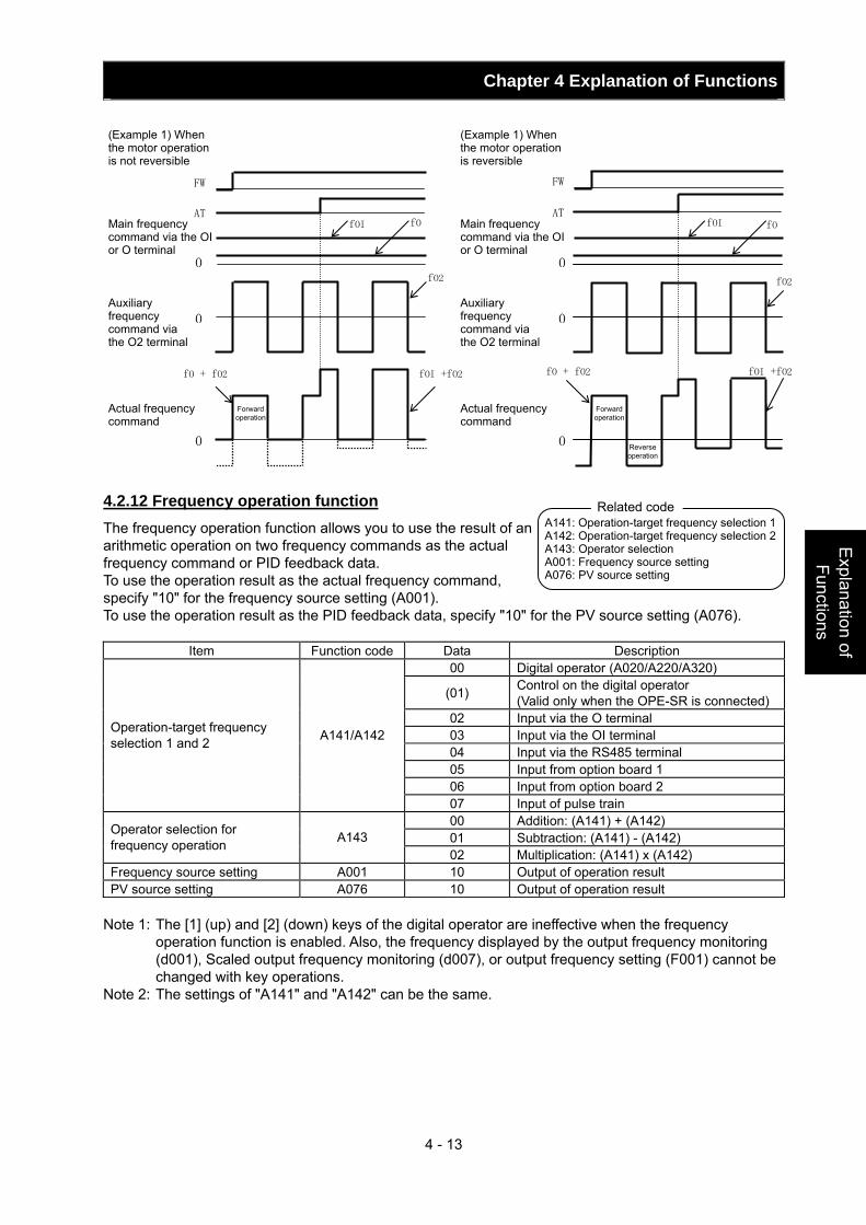
Chapter 4 Explanation of Functions
4 - 13
Explanation of Functions
4.2.12 Frequency operation function The frequency operation function allows you to use the result of an arithmetic operation on two frequency commands as the actual frequency command or PID feedback data. To use the operation result as the actual frequency command, specify "10" for the frequency source setting (A001). To use the operation result as the PID feedback data, specify "10" for the PV source setting (A076).
Item Function code Data Description 00 Digital operator (A020/A220/A320)
(01) Control on the digital operator (Valid only when the OPE-SR is connected)
02 Input via the O terminal 03 Input via the OI terminal 04 Input via the RS485 terminal 05 Input from option board 1 06 Input from option board 2
Operation-target frequency selection 1 and 2 A141/A142
07 Input of pulse train 00 Addition: (A141) + (A142) 01 Subtraction: (A141) - (A142) Operator selection for
frequency operation A143 02 Multiplication: (A141) x (A142)
Frequency source setting A001 10 Output of operation result PV source setting A076 10 Output of operation result
Note 1: The [1] (up) and [2] (down) keys of the digital operator are ineffective when the frequency
operation function is enabled. Also, the frequency displayed by the output frequency monitoring (d001), Scaled output frequency monitoring (d007), or output frequency setting (F001) cannot be changed with key operations.
Note 2: The settings of "A141" and "A142" can be the same.
fO
fO2
fOI +fO2
0
AT
fOI
0
0
fO + fO2
FW FW
ATfOI
0
0
0
fO
fO2
fO + fO2 fOI +fO2
(Example 1) When the motor operation is not reversible
Main frequency command via the OI or O terminal
Auxiliary frequency command via the O2 terminal
Actual frequency command
Forward operation
Forward operation
Reverse operation
(Example 1) When the motor operation is reversible
Main frequency command via the OI or O terminal
Auxiliary frequency command via the O2 terminal
Actual frequency command
A141: Operation-target frequency selection 1A142: Operation-target frequency selection 2A143: Operator selection A001: Frequency source setting A076: PV source setting
Related code
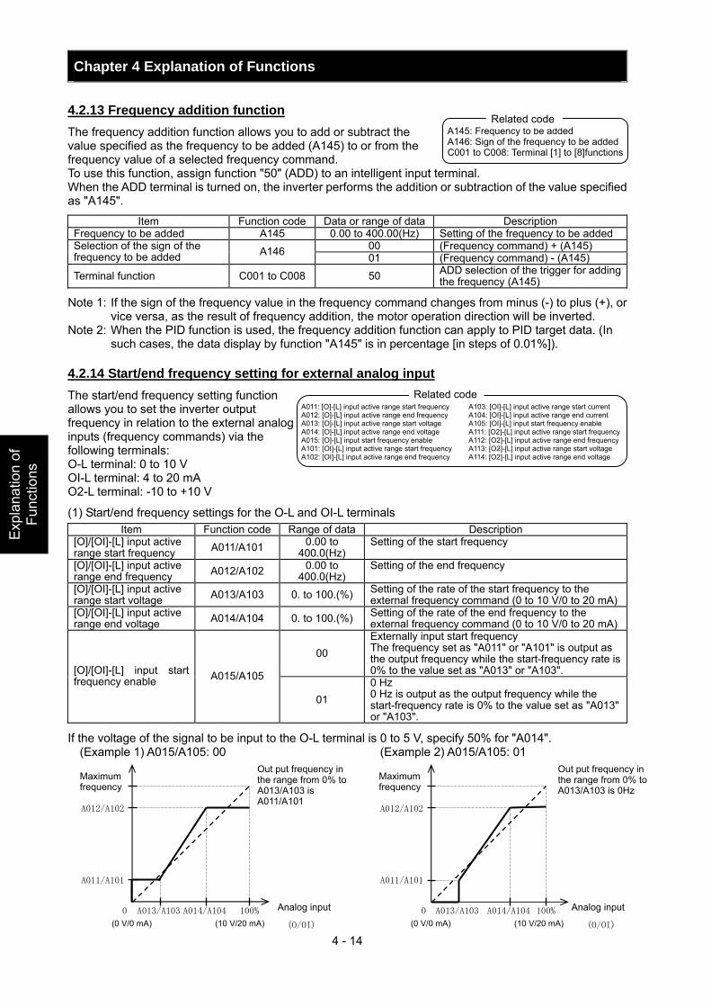
Chapter 4 Explanation of Functions
4 - 14
Exp
lana
tion
of
Func
tions
4.2.13 Frequency addition function The frequency addition function allows you to add or subtract the value specified as the frequency to be added (A145) to or from the frequency value of a selected frequency command. To use this function, assign function "50" (ADD) to an intelligent input terminal. When the ADD terminal is turned on, the inverter performs the addition or subtraction of the value specified as "A145".
Item Function code Data or range of data Description Frequency to be added A145 0.00 to 400.00(Hz) Setting of the frequency to be added
00 (Frequency command) + (A145) Selection of the sign of the frequency to be added A146 01 (Frequency command) - (A145)
Terminal function C001 to C008 50 ADD selection of the trigger for adding the frequency (A145)
Note 1: If the sign of the frequency value in the frequency command changes from minus (-) to plus (+), or vice versa, as the result of frequency addition, the motor operation direction will be inverted.
Note 2: When the PID function is used, the frequency addition function can apply to PID target data. (In such cases, the data display by function "A145" is in percentage [in steps of 0.01%]).
4.2.14 Start/end frequency setting for external analog input The start/end frequency setting function allows you to set the inverter output frequency in relation to the external analog inputs (frequency commands) via the following terminals: O-L terminal: 0 to 10 V OI-L terminal: 4 to 20 mA O2-L terminal: -10 to +10 V
(1) Start/end frequency settings for the O-L and OI-L terminals Item Function code Range of data Description
[O]/[OI]-[L] input active range start frequency A011/A101 0.00 to
400.0(Hz) Setting of the start frequency
[O]/[OI]-[L] input active range end frequency A012/A102 0.00 to
400.0(Hz) Setting of the end frequency
[O]/[OI]-[L] input active range start voltage A013/A103 0. to 100.(%) Setting of the rate of the start frequency to the
external frequency command (0 to 10 V/0 to 20 mA)[O]/[OI]-[L] input active range end voltage A014/A104 0. to 100.(%) Setting of the rate of the end frequency to the
external frequency command (0 to 10 V/0 to 20 mA)
00 Externally input start frequency The frequency set as "A011" or "A101" is output as the output frequency while the start-frequency rate is 0% to the value set as "A013" or "A103". [O]/[OI]-[L] input start
frequency enable A015/A105
01 0 Hz 0 Hz is output as the output frequency while the start-frequency rate is 0% to the value set as "A013" or "A103".
If the voltage of the signal to be input to the O-L terminal is 0 to 5 V, specify 50% for "A014". (Example 1) A015/A105: 00 (Example 2) A015/A105: 01
A145: Frequency to be added A146: Sign of the frequency to be added C001 to C008: Terminal [1] to [8]functions
Related code
A011: [O]-[L] input active range start frequency A012: [O]-[L] input active range end frequency A013: [O]-[L] input active range start voltage A014: [O]-[L] input active range end voltage A015: [O]-[L] input start frequency enable A101: [OI]-[L] input active range start frequency A102: [OI]-[L] input active range end frequency
A103: [OI]-[L] input active range start current A104: [OI]-[L] input active range end current A105: [OI]-[L] input start frequency enable A111: [O2]-[L] input active range start frequency A112: [O2]-[L] input active range end frequency A113: [O2]-[L] input active range start voltage A114: [O2]-[L] input active range end voltage
Related code
A012/A102
A011/A101
0 A013/A103 A014/A104 100%
(0 V/0 mA) (10 V/20 mA)
(O/OI)
Maximum frequency
Analog input
Out put frequency in the range from 0% to A013/A103 is A011/A101
A012/A102
A011/A101
0 A013/A103 A014/A104 100%
(0 V/0 mA) (10 V/20 mA) (O/OI)
Maximum frequency
Analog input
Out put frequency in the range from 0% to A013/A103 is 0Hz

Chapter 4 Explanation of Functions
4 - 15
Explanation of Functions
(2) Start/end frequency settings for the O2-L terminal Item Function code Range of data Description Remarks
02 start frequency A111 -400. to 400.(Hz) Setting of the start frequency 02 end frequency A112 -400. to 400.(Hz) Setting of the end frequency
02 start-frequency rate A113 -100. to 100.(%)
Setting of the rate of the start frequency to the external frequency command (-10 to +10 V) (*1)
02 end-frequency rate A114 -100. to 100.(%)
Setting of the rate of the end frequency to the external frequency command (-10 to +10 V) (*1)
(Example 3)
*1 The frequency rates correspond to the voltages
(-10 to +10 V) of the external frequency command as follows:
-10 to 0 V: -100% to 0% 0 to +10 V: 0% to 100% For example, if the voltage of the signal to be input to the O2-L terminal is -5 to +5 V, specify 50% for "A114". 4.2.15 External analog input (O/OI/O2) filter setting The external analog input filter setting function allows you to set the input-voltage/input-current sampling time to be applied when frequency commands are input as external analog signals. You can use this filter function effectively for removing noise from the frequency-setting circuit signal. If the noise disables the stable operation of the inverter, increase the setting. Setting a larger value makes the inverter response slower. The filtering constant is "set value (1 to 30) x 2 ms." When the setting is "31" (factory setting), a hysteresis of ±0.1 Hz is added to the filtering constant (500 ms).
Item Function code Range of data Description
External frequency filter time const. A016 1. to 30. or 31.
Setting of 1. to 30.: "Set value x 2" ms filter Setting of 31.: 500 ms filter (fixed) with hysteresis of ±0.1 Hz
4.2.16 V/f gain setting The V/f gain setting function allows you to change the inverter output voltage by specifying the rate of the output voltage to the voltage (100%) selected with the AVR voltage select function (A082). If the motor operation is cranky, try to increase the gain setting.
Item Function code Range of data Description V/f gain setting A045 20. to 100. (%) Setting of the rate of reducing the output voltage
(Example 3)
A111 A114
A113
A112(-10V)-100%
(+10V)
100%
Maximum frequency for forward operation
Analog input (O2)
Maximum frequency for reverse operation
A045: V/f gain setting A082: AVR voltage select
Related code
A045
AVR voltage select (100%)
Base frequency
Maximum frequency
A016: External frequency filter time const.
Related code
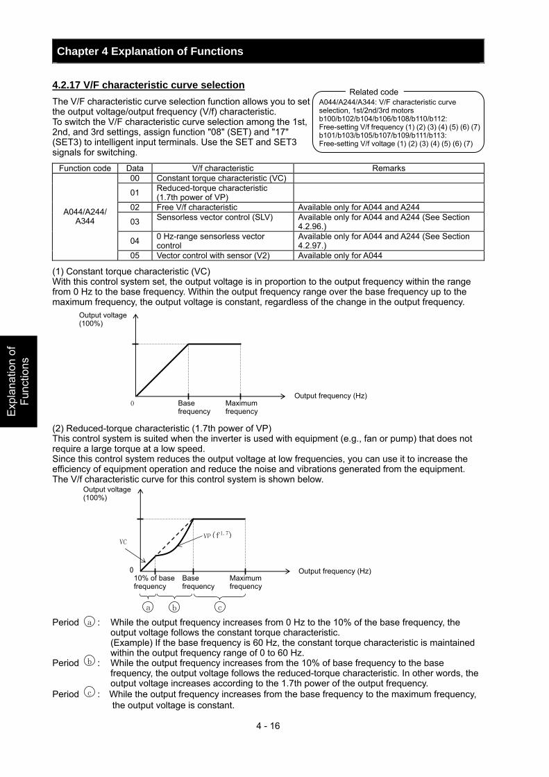
Chapter 4 Explanation of Functions
4 - 16
Exp
lana
tion
of
Func
tions
4.2.17 V/F characteristic curve selection The V/F characteristic curve selection function allows you to set the output voltage/output frequency (V/f) characteristic. To switch the V/F characteristic curve selection among the 1st, 2nd, and 3rd settings, assign function "08" (SET) and "17" (SET3) to intelligent input terminals. Use the SET and SET3 signals for switching.
Function code Data V/f characteristic Remarks 00 Constant torque characteristic (VC)
01 Reduced-torque characteristic (1.7th power of VP)
02 Free V/f characteristic Available only for A044 and A244
03 Sensorless vector control (SLV) Available only for A044 and A244 (See Section 4.2.96.)
04 0 Hz-range sensorless vector control
Available only for A044 and A244 (See Section 4.2.97.)
A044/A244/ A344
05 Vector control with sensor (V2) Available only for A044
(1) Constant torque characteristic (VC) With this control system set, the output voltage is in proportion to the output frequency within the range from 0 Hz to the base frequency. Within the output frequency range over the base frequency up to the maximum frequency, the output voltage is constant, regardless of the change in the output frequency.
(2) Reduced-torque characteristic (1.7th power of VP) This control system is suited when the inverter is used with equipment (e.g., fan or pump) that does not require a large torque at a low speed. Since this control system reduces the output voltage at low frequencies, you can use it to increase the efficiency of equipment operation and reduce the noise and vibrations generated from the equipment. The V/f characteristic curve for this control system is shown below. Period : While the output frequency increases from 0 Hz to the 10% of the base frequency, the
output voltage follows the constant torque characteristic. (Example) If the base frequency is 60 Hz, the constant torque characteristic is maintained
within the output frequency range of 0 to 60 Hz. Period : While the output frequency increases from the 10% of base frequency to the base
frequency, the output voltage follows the reduced-torque characteristic. In other words, the output voltage increases according to the 1.7th power of the output frequency.
Period : While the output frequency increases from the base frequency to the maximum frequency, the output voltage is constant.
A044/A244/A344: V/F characteristic curve selection, 1st/2nd/3rd motors b100/b102/b104/b106/b108/b110/b112: Free-setting V/f frequency (1) (2) (3) (4) (5) (6) (7)b101/b103/b105/b107/b109/b111/b113: Free-setting V/f voltage (1) (2) (3) (4) (5) (6) (7)
Related code
0
Output voltage (100%)
Base frequency
Maximum frequency
Output frequency (Hz)
0
VP(f1.7)VC
a b c
Output voltage (100%)
Base frequency
Maximum frequency
Output frequency (Hz) 10% of base frequency
a
b
c
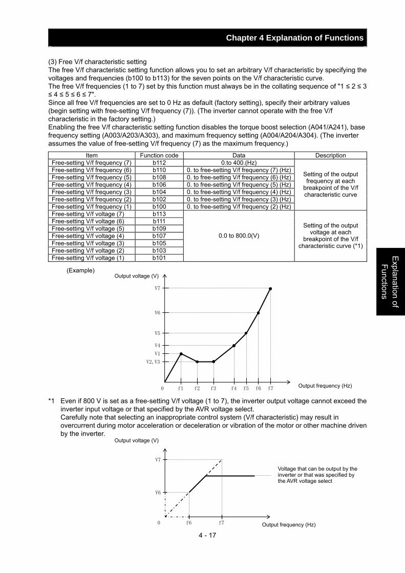
Chapter 4 Explanation of Functions
4 - 17
Explanation of Functions
(3) Free V/f characteristic setting The free V/f characteristic setting function allows you to set an arbitrary V/f characteristic by specifying the voltages and frequencies (b100 to b113) for the seven points on the V/f characteristic curve. The free V/f frequencies (1 to 7) set by this function must always be in the collating sequence of "1 ≤ 2 ≤ 3 ≤ 4 ≤ 5 ≤ 6 ≤ 7". Since all free V/f frequencies are set to 0 Hz as default (factory setting), specify their arbitrary values (begin setting with free-setting V/f frequency (7)). (The inverter cannot operate with the free V/f characteristic in the factory setting.) Enabling the free V/f characteristic setting function disables the torque boost selection (A041/A241), base frequency setting (A003/A203/A303), and maximum frequency setting (A004/A204/A304). (The inverter assumes the value of free-setting V/f frequency (7) as the maximum frequency.)
Item Function code Data Description Free-setting V/f frequency (7) b112 0.to 400.(Hz) Free-setting V/f frequency (6) b110 0. to free-setting V/f frequency (7) (Hz) Free-setting V/f frequency (5) b108 0. to free-setting V/f frequency (6) (Hz) Free-setting V/f frequency (4) b106 0. to free-setting V/f frequency (5) (Hz) Free-setting V/f frequency (3) b104 0. to free-setting V/f frequency (4) (Hz) Free-setting V/f frequency (2) b102 0. to free-setting V/f frequency (3) (Hz) Free-setting V/f frequency (1) b100 0. to free-setting V/f frequency (2) (Hz)
Setting of the output frequency at each
breakpoint of the V/f characteristic curve
Free-setting V/f voltage (7) b113 Free-setting V/f voltage (6) b111 Free-setting V/f voltage (5) b109 Free-setting V/f voltage (4) b107 Free-setting V/f voltage (3) b105 Free-setting V/f voltage (2) b103 Free-setting V/f voltage (1) b101
0.0 to 800.0(V)
Setting of the output voltage at each
breakpoint of the V/f characteristic curve (*1)
(Example) *1 Even if 800 V is set as a free-setting V/f voltage (1 to 7), the inverter output voltage cannot exceed the
inverter input voltage or that specified by the AVR voltage select. Carefully note that selecting an inappropriate control system (V/f characteristic) may result in
overcurrent during motor acceleration or deceleration or vibration of the motor or other machine driven by the inverter.
f1 f2 f3 f4 f5 f6 f70
V2,V3
V1
V5
V6
V7
V4
Output voltage (V)
Output frequency (Hz)
0 f6 f7
V6
V7
Voltage that can be output by the inverter or that was specified by the AVR voltage select
Output frequency (Hz)
Output voltage (V)
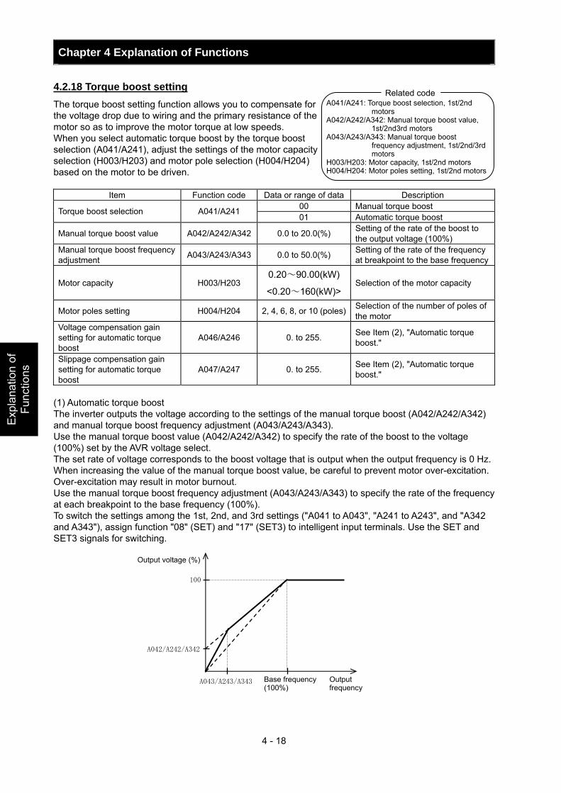
Chapter 4 Explanation of Functions
4 - 18
Exp
lana
tion
of
Func
tions
4.2.18 Torque boost setting The torque boost setting function allows you to compensate for the voltage drop due to wiring and the primary resistance of the motor so as to improve the motor torque at low speeds. When you select automatic torque boost by the torque boost selection (A041/A241), adjust the settings of the motor capacity selection (H003/H203) and motor pole selection (H004/H204) based on the motor to be driven.
Item Function code Data or range of data Description 00 Manual torque boost Torque boost selection A041/A241 01 Automatic torque boost
Manual torque boost value A042/A242/A342 0.0 to 20.0(%) Setting of the rate of the boost to the output voltage (100%)
Manual torque boost frequency adjustment A043/A243/A343 0.0 to 50.0(%) Setting of the rate of the frequency
at breakpoint to the base frequency
Motor capacity H003/H203 0.20~90.00(kW)
<0.20~160(kW)> Selection of the motor capacity
Motor poles setting H004/H204 2, 4, 6, 8, or 10 (poles) Selection of the number of poles of the motor
Voltage compensation gain setting for automatic torque boost
A046/A246 0. to 255. See Item (2), "Automatic torque boost."
Slippage compensation gain setting for automatic torque boost
A047/A247 0. to 255. See Item (2), "Automatic torque boost."
(1) Automatic torque boost The inverter outputs the voltage according to the settings of the manual torque boost (A042/A242/A342) and manual torque boost frequency adjustment (A043/A243/A343). Use the manual torque boost value (A042/A242/A342) to specify the rate of the boost to the voltage (100%) set by the AVR voltage select. The set rate of voltage corresponds to the boost voltage that is output when the output frequency is 0 Hz. When increasing the value of the manual torque boost value, be careful to prevent motor over-excitation. Over-excitation may result in motor burnout. Use the manual torque boost frequency adjustment (A043/A243/A343) to specify the rate of the frequency at each breakpoint to the base frequency (100%). To switch the settings among the 1st, 2nd, and 3rd settings ("A041 to A043", "A241 to A243", and "A342 and A343"), assign function "08" (SET) and "17" (SET3) to intelligent input terminals. Use the SET and SET3 signals for switching.
A041/A241: Torque boost selection, 1st/2nd motors
A042/A242/A342: Manual torque boost value, 1st/2nd3rd motors
A043/A243/A343: Manual torque boost frequency adjustment, 1st/2nd/3rd motors
H003/H203: Motor capacity, 1st/2nd motors H004/H204: Motor poles setting, 1st/2nd motors
Related code
A042/A242/A342
A043/A243/A343
100
Output voltage (%)
Base frequency (100%)
Output frequency
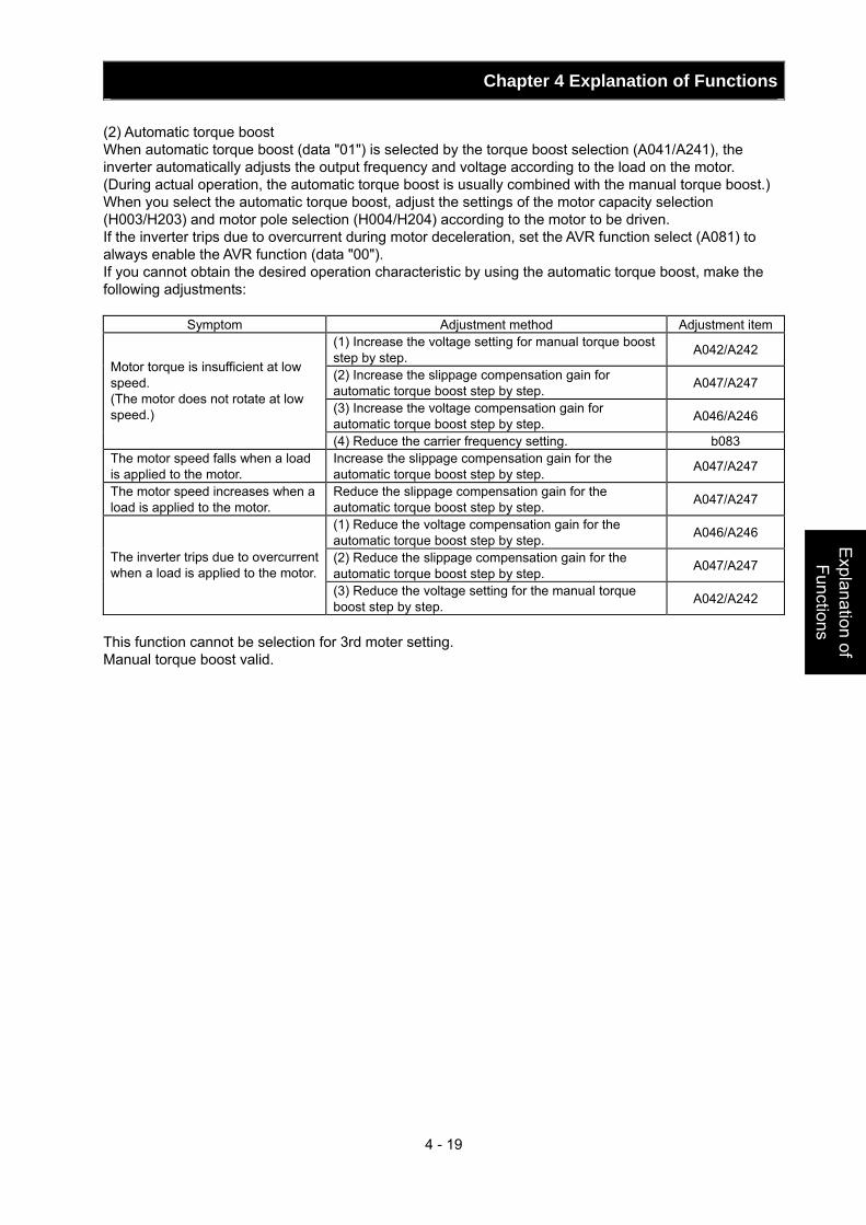
Chapter 4 Explanation of Functions
4 - 19
Explanation of Functions
(2) Automatic torque boost When automatic torque boost (data "01") is selected by the torque boost selection (A041/A241), the inverter automatically adjusts the output frequency and voltage according to the load on the motor. (During actual operation, the automatic torque boost is usually combined with the manual torque boost.) When you select the automatic torque boost, adjust the settings of the motor capacity selection (H003/H203) and motor pole selection (H004/H204) according to the motor to be driven. If the inverter trips due to overcurrent during motor deceleration, set the AVR function select (A081) to always enable the AVR function (data "00"). If you cannot obtain the desired operation characteristic by using the automatic torque boost, make the following adjustments:
Symptom Adjustment method Adjustment item(1) Increase the voltage setting for manual torque boost step by step. A042/A242
(2) Increase the slippage compensation gain for automatic torque boost step by step. A047/A247
(3) Increase the voltage compensation gain for automatic torque boost step by step. A046/A246
Motor torque is insufficient at low speed. (The motor does not rotate at low speed.)
(4) Reduce the carrier frequency setting. b083 The motor speed falls when a load is applied to the motor.
Increase the slippage compensation gain for the automatic torque boost step by step. A047/A247
The motor speed increases when a load is applied to the motor.
Reduce the slippage compensation gain for the automatic torque boost step by step. A047/A247
(1) Reduce the voltage compensation gain for the automatic torque boost step by step. A046/A246
(2) Reduce the slippage compensation gain for the automatic torque boost step by step. A047/A247 The inverter trips due to overcurrent
when a load is applied to the motor. (3) Reduce the voltage setting for the manual torque boost step by step. A042/A242
This function cannot be selection for 3rd moter setting. Manual torque boost valid.
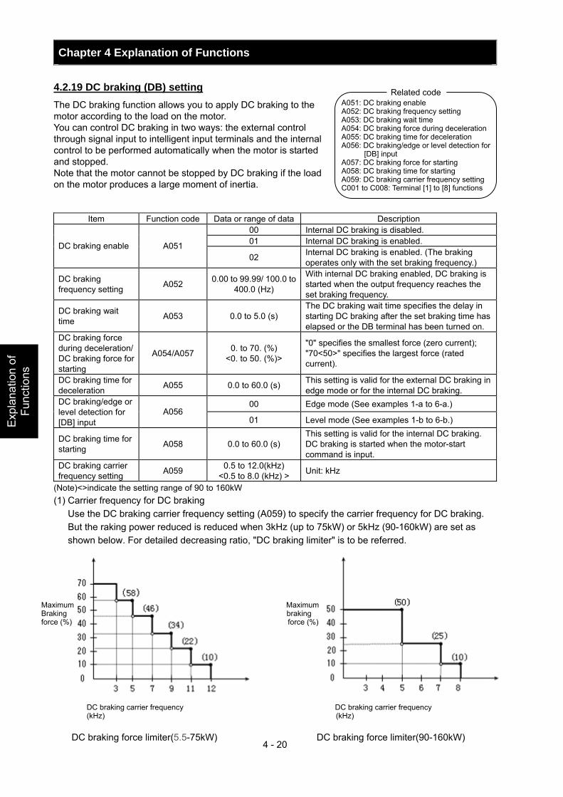
Chapter 4 Explanation of Functions
4 - 20
Exp
lana
tion
of
Func
tions
4.2.19 DC braking (DB) setting The DC braking function allows you to apply DC braking to the motor according to the load on the motor. You can control DC braking in two ways: the external control through signal input to intelligent input terminals and the internal control to be performed automatically when the motor is started and stopped. Note that the motor cannot be stopped by DC braking if the load on the motor produces a large moment of inertia.
Item Function code Data or range of data Description 00 Internal DC braking is disabled. 01 Internal DC braking is enabled. DC braking enable A051 02 Internal DC braking is enabled. (The braking
operates only with the set braking frequency.)
DC braking frequency setting A052 0.00 to 99.99/ 100.0 to
400.0 (Hz)
With internal DC braking enabled, DC braking is started when the output frequency reaches the set braking frequency.
DC braking wait time A053 0.0 to 5.0 (s)
The DC braking wait time specifies the delay in starting DC braking after the set braking time has elapsed or the DB terminal has been turned on.
DC braking force during deceleration/ DC braking force for starting
A054/A057 0. to 70. (%) <0. to 50. (%)>
"0" specifies the smallest force (zero current); "70<50>" specifies the largest force (rated current).
DC braking time for deceleration A055 0.0 to 60.0 (s) This setting is valid for the external DC braking in
edge mode or for the internal DC braking. 00 Edge mode (See examples 1-a to 6-a.) DC braking/edge or
level detection for [DB] input
A056 01 Level mode (See examples 1-b to 6-b.)
DC braking time for starting A058 0.0 to 60.0 (s)
This setting is valid for the internal DC braking. DC braking is started when the motor-start command is input.
DC braking carrier frequency setting A059 0.5 to 12.0(kHz)
<0.5 to 8.0 (kHz) > Unit: kHz
(Note)<>indicate the setting range of 90 to 160kW (1) Carrier frequency for DC braking Use the DC braking carrier frequency setting (A059) to specify the carrier frequency for DC braking.
But the raking power reduced is reduced when 3kHz (up to 75kW) or 5kHz (90-160kW) are set as shown below. For detailed decreasing ratio, "DC braking limiter" is to be referred.
A051: DC braking enable A052: DC braking frequency setting A053: DC braking wait time A054: DC braking force during deceleration A055: DC braking time for deceleration A056: DC braking/edge or level detection for
[DB] input A057: DC braking force for starting A058: DC braking time for starting A059: DC braking carrier frequency setting C001 to C008: Terminal [1] to [8] functions
Related code
Maximum Maximum Braking braking force (%) force (%)
DC braking carrier frequency DC braking carrier frequency (kHz) (kHz)
DC braking force limiter(5.5-75kW) DC braking force limiter(90-160kW)
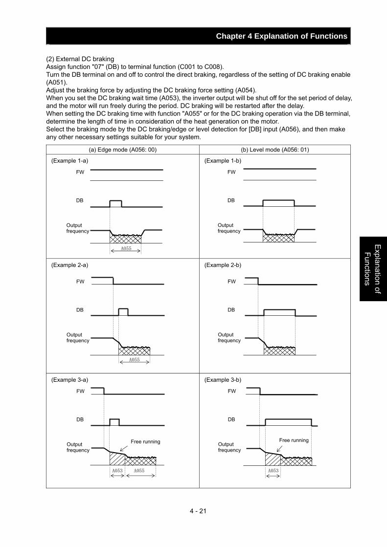
Chapter 4 Explanation of Functions
4 - 21
Explanation of Functions
(2) External DC braking Assign function "07" (DB) to terminal function (C001 to C008). Turn the DB terminal on and off to control the direct braking, regardless of the setting of DC braking enable (A051). Adjust the braking force by adjusting the DC braking force setting (A054). When you set the DC braking wait time (A053), the inverter output will be shut off for the set period of delay, and the motor will run freely during the period. DC braking will be restarted after the delay. When setting the DC braking time with function "A055" or for the DC braking operation via the DB terminal, determine the length of time in consideration of the heat generation on the motor. Select the braking mode by the DC braking/edge or level detection for [DB] input (A056), and then make any other necessary settings suitable for your system.
(a) Edge mode (A056: 00) (b) Level mode (A056: 01)
(Example 1-a)
(Example 1-b)
(Example 2-a)
(Example 2-b)
(Example 3-a)
(Example 3-b)
A055
A055
A053
A055 A053
Free running Free running
FW
DB
Output frequency
FW
DB
Output frequency
FW
DB
Output frequency
FW
DB
Output frequency
FW
DB
Output frequency
FW
DB
Output frequency
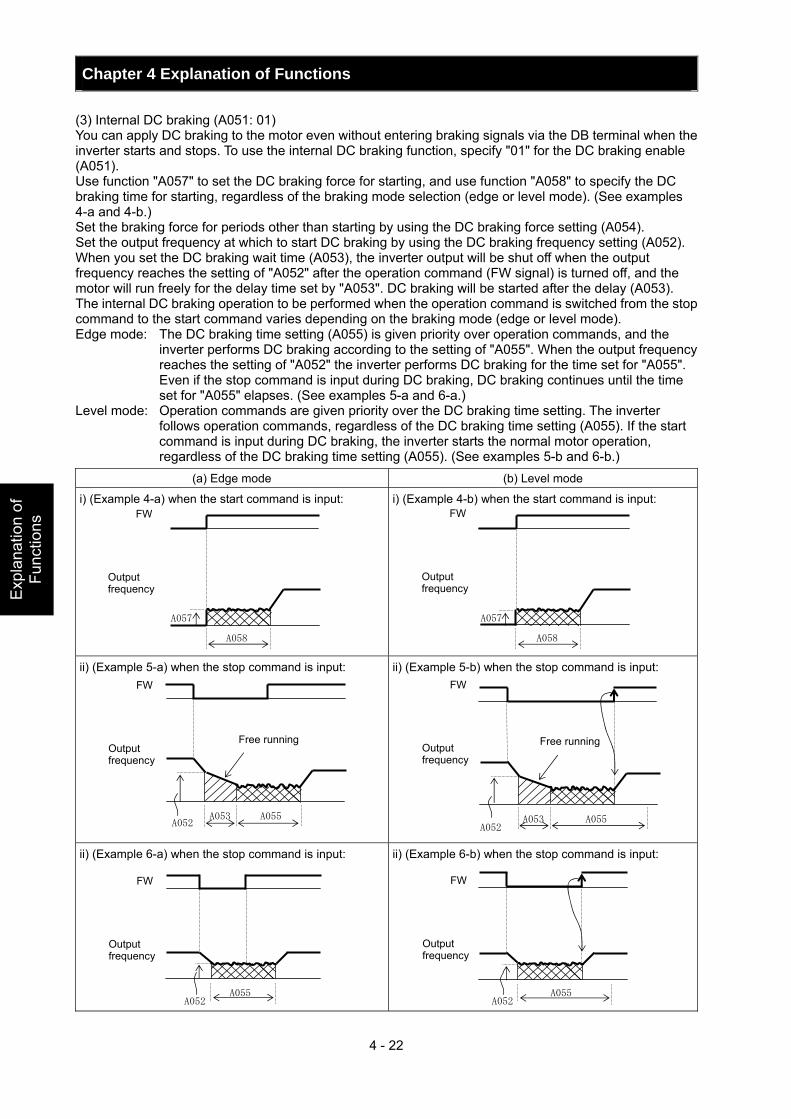
Chapter 4 Explanation of Functions
4 - 22
Exp
lana
tion
of
Func
tions
(3) Internal DC braking (A051: 01) You can apply DC braking to the motor even without entering braking signals via the DB terminal when the inverter starts and stops. To use the internal DC braking function, specify "01" for the DC braking enable (A051). Use function "A057" to set the DC braking force for starting, and use function "A058" to specify the DC braking time for starting, regardless of the braking mode selection (edge or level mode). (See examples 4-a and 4-b.) Set the braking force for periods other than starting by using the DC braking force setting (A054). Set the output frequency at which to start DC braking by using the DC braking frequency setting (A052). When you set the DC braking wait time (A053), the inverter output will be shut off when the output frequency reaches the setting of "A052" after the operation command (FW signal) is turned off, and the motor will run freely for the delay time set by "A053". DC braking will be started after the delay (A053). The internal DC braking operation to be performed when the operation command is switched from the stop command to the start command varies depending on the braking mode (edge or level mode). Edge mode: The DC braking time setting (A055) is given priority over operation commands, and the
inverter performs DC braking according to the setting of "A055". When the output frequency reaches the setting of "A052" the inverter performs DC braking for the time set for "A055". Even if the stop command is input during DC braking, DC braking continues until the time set for "A055" elapses. (See examples 5-a and 6-a.)
Level mode: Operation commands are given priority over the DC braking time setting. The inverter follows operation commands, regardless of the DC braking time setting (A055). If the start command is input during DC braking, the inverter starts the normal motor operation, regardless of the DC braking time setting (A055). (See examples 5-b and 6-b.)
(a) Edge mode (b) Level mode
i) (Example 4-a) when the start command is input:
i) (Example 4-b) when the start command is input:
ii) (Example 5-a) when the stop command is input:
ii) (Example 5-b) when the stop command is input:
ii) (Example 6-a) when the stop command is input:
ii) (Example 6-b) when the stop command is input:
A053 A055 A052
A053
A055 A052
A058
A057
A058
A057
A052 A055
A052 A055
Free running Free running
FW
Output frequency
FW
Output frequency
FW
Output frequency
FW
Output frequency
FW
Output frequency
FW
Output frequency
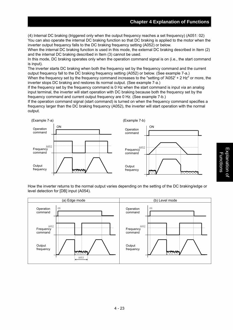
Chapter 4 Explanation of Functions
4 - 23
Explanation of Functions
(4) Internal DC braking (triggered only when the output frequency reaches a set frequency) (A051: 02) You can also operate the internal DC braking function so that DC braking is applied to the motor when the inverter output frequency falls to the DC braking frequency setting (A052) or below. When the internal DC braking function is used in this mode, the external DC braking described in Item (2) and the internal DC braking described in Item (3) cannot be used. In this mode, DC braking operates only when the operation command signal is on (i.e., the start command is input). The inverter starts DC braking when both the frequency set by the frequency command and the current output frequency fall to the DC braking frequency setting (A052) or below. (See example 7-a.) When the frequency set by the frequency command increases to the "setting of 'A052' + 2 Hz" or more, the inverter stops DC braking and restores its normal output. (See example 7-a.) If the frequency set by the frequency command is 0 Hz when the start command is input via an analog input terminal, the inverter will start operation with DC braking because both the frequency set by the frequency command and current output frequency are 0 Hz. (See example 7-b.) If the operation command signal (start command) is turned on when the frequency command specifies a frequency larger than the DC braking frequency (A052), the inverter will start operation with the normal output.
(Example 7-a) (Example 7-b) How the inverter returns to the normal output varies depending on the setting of the DC braking/edge or level detection for [DB] input (A054).
(a) Edge mode (b) Level mode
A052
A052
ON ON
Operation command
Frequency command
Output frequency
Operation command
Frequency command
Output frequency
A052
ON
A053
A052
ONOperation command
Frequency command
Output frequency
Operation command
Frequency command
Output frequency
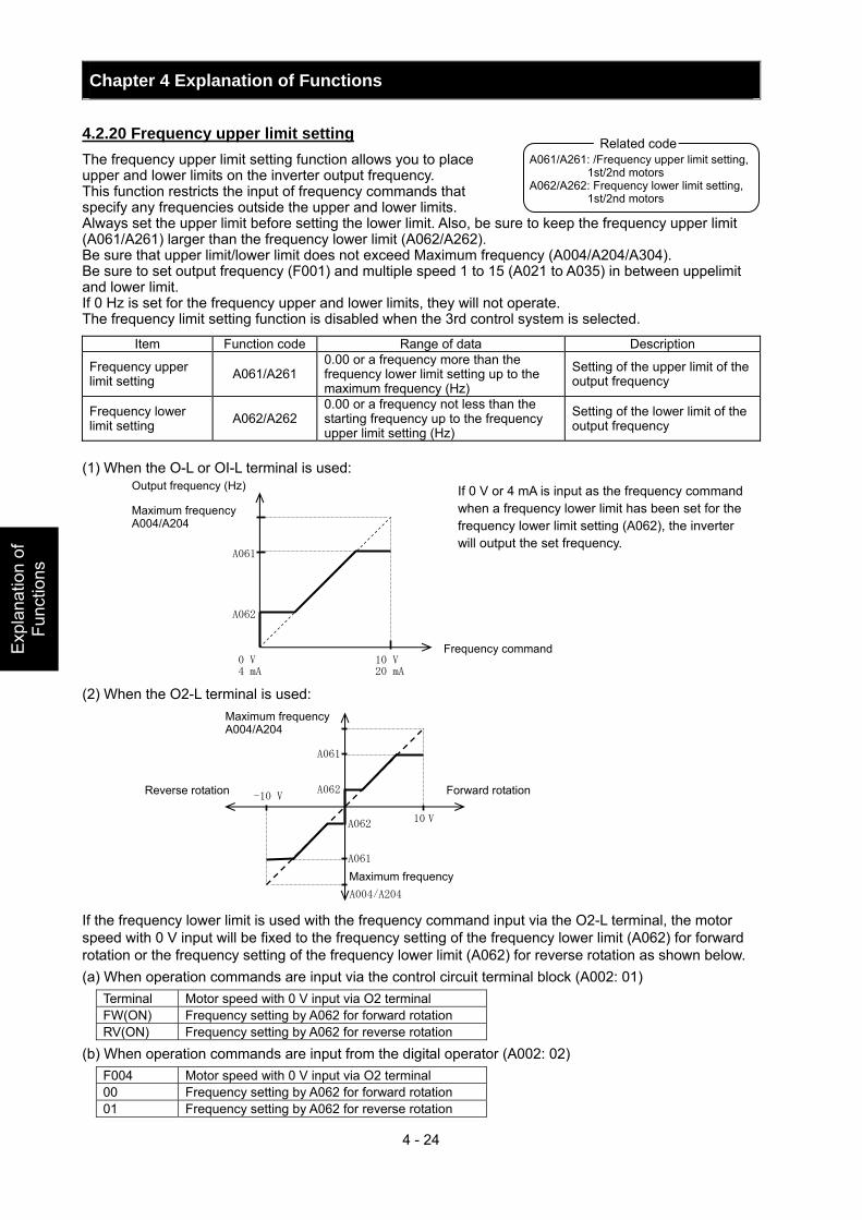
Chapter 4 Explanation of Functions
4 - 24
Exp
lana
tion
of
Func
tions
4.2.20 Frequency upper limit setting The frequency upper limit setting function allows you to place upper and lower limits on the inverter output frequency. This function restricts the input of frequency commands that specify any frequencies outside the upper and lower limits. Always set the upper limit before setting the lower limit. Also, be sure to keep the frequency upper limit (A061/A261) larger than the frequency lower limit (A062/A262). Be sure that upper limit/lower limit does not exceed Maximum frequency (A004/A204/A304). Be sure to set output frequency (F001) and multiple speed 1 to 15 (A021 to A035) in between uppelimit and lower limit. If 0 Hz is set for the frequency upper and lower limits, they will not operate. The frequency limit setting function is disabled when the 3rd control system is selected.
Item Function code Range of data Description
Frequency upper limit setting A061/A261
0.00 or a frequency more than the frequency lower limit setting up to the maximum frequency (Hz)
Setting of the upper limit of the output frequency
Frequency lower limit setting A062/A262
0.00 or a frequency not less than the starting frequency up to the frequency upper limit setting (Hz)
Setting of the lower limit of the output frequency
(1) When the O-L or OI-L terminal is used: (2) When the O2-L terminal is used: If the frequency lower limit is used with the frequency command input via the O2-L terminal, the motor speed with 0 V input will be fixed to the frequency setting of the frequency lower limit (A062) for forward rotation or the frequency setting of the frequency lower limit (A062) for reverse rotation as shown below. (a) When operation commands are input via the control circuit terminal block (A002: 01)
Terminal Motor speed with 0 V input via O2 terminal FW(ON) Frequency setting by A062 for forward rotation RV(ON) Frequency setting by A062 for reverse rotation
(b) When operation commands are input from the digital operator (A002: 02) F004 Motor speed with 0 V input via O2 terminal 00 Frequency setting by A062 for forward rotation 01 Frequency setting by A062 for reverse rotation
A061/A261: /Frequency upper limit setting, 1st/2nd motors
A062/A262: Frequency lower limit setting, 1st/2nd motors
Related code
A062
A061
Output frequency (Hz)
Frequency command 0 V4 mA
10 V20 mA
Maximum frequency A004/A204
If 0 V or 4 mA is input as the frequency command when a frequency lower limit has been set for the frequency lower limit setting (A062), the inverter will output the set frequency.
A062
A061
A004/A204
A062
A061
10 V
-10 V
Maximum frequency A004/A204
Reverse rotation Forward rotation
Maximum frequency
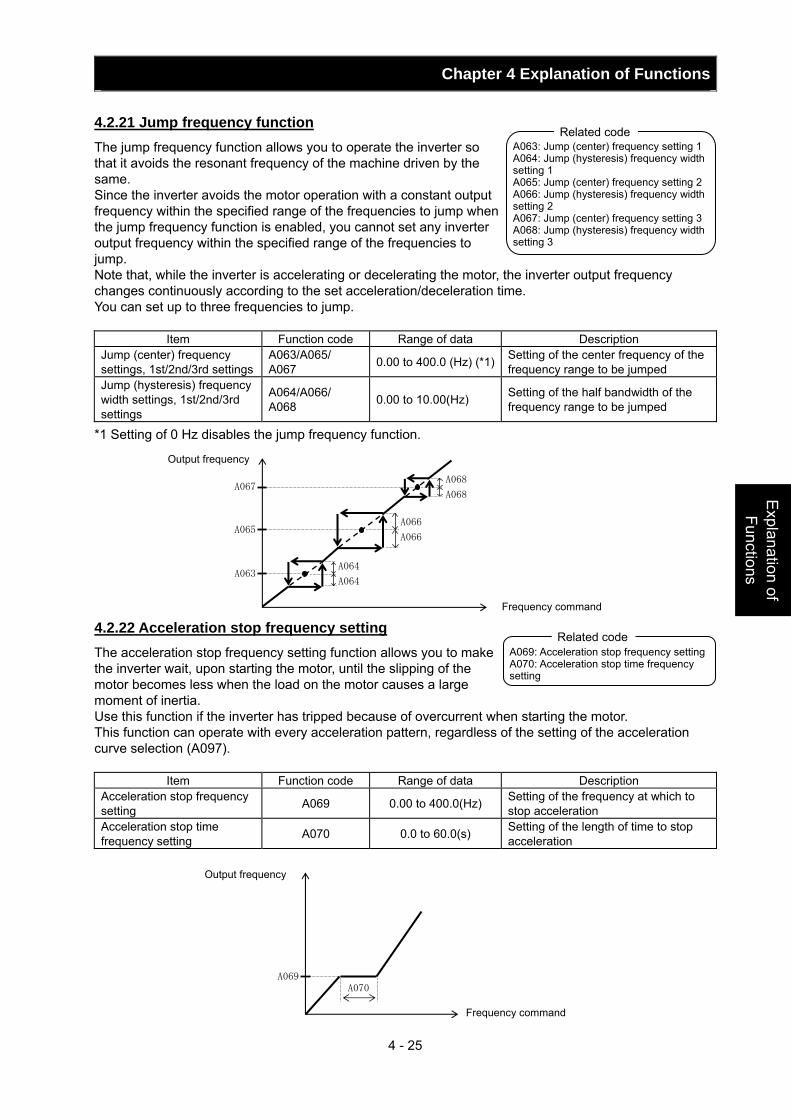
Chapter 4 Explanation of Functions
4 - 25
Explanation of Functions
4.2.21 Jump frequency function The jump frequency function allows you to operate the inverter so that it avoids the resonant frequency of the machine driven by the same. Since the inverter avoids the motor operation with a constant output frequency within the specified range of the frequencies to jump when the jump frequency function is enabled, you cannot set any inverter output frequency within the specified range of the frequencies to jump. Note that, while the inverter is accelerating or decelerating the motor, the inverter output frequency changes continuously according to the set acceleration/deceleration time. You can set up to three frequencies to jump.
Item Function code Range of data Description Jump (center) frequency settings, 1st/2nd/3rd settings
A063/A065/ A067 0.00 to 400.0 (Hz) (*1) Setting of the center frequency of the
frequency range to be jumped Jump (hysteresis) frequency width settings, 1st/2nd/3rd settings
A064/A066/ A068 0.00 to 10.00(Hz) Setting of the half bandwidth of the
frequency range to be jumped
*1 Setting of 0 Hz disables the jump frequency function. 4.2.22 Acceleration stop frequency setting The acceleration stop frequency setting function allows you to make the inverter wait, upon starting the motor, until the slipping of the motor becomes less when the load on the motor causes a large moment of inertia. Use this function if the inverter has tripped because of overcurrent when starting the motor. This function can operate with every acceleration pattern, regardless of the setting of the acceleration curve selection (A097).
Item Function code Range of data Description Acceleration stop frequency setting A069 0.00 to 400.0(Hz) Setting of the frequency at which to
stop acceleration Acceleration stop time frequency setting A070 0.0 to 60.0(s) Setting of the length of time to stop
acceleration
A063: Jump (center) frequency setting 1 A064: Jump (hysteresis) frequency width setting 1 A065: Jump (center) frequency setting 2 A066: Jump (hysteresis) frequency width setting 2 A067: Jump (center) frequency setting 3 A068: Jump (hysteresis) frequency width setting 3
Related code
A063
A065
A067
A064
A064
A066
A066
A068
A068
Output frequency
Frequency command
A069: Acceleration stop frequency setting A070: Acceleration stop time frequency setting
Related code
A070A069
Output frequency
Frequency command
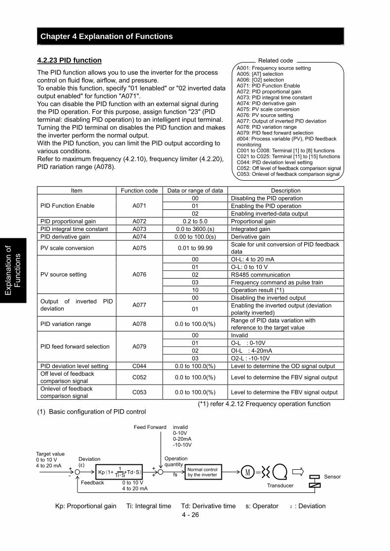
Chapter 4 Explanation of Functions
4 - 26
Exp
lana
tion
of
Func
tions
4.2.23 PID function The PID function allows you to use the inverter for the process control on fluid flow, airflow, and pressure. To enable this function, specify "01 lenabled" or "02 inverted data output enabled" for function "A071". You can disable the PID function with an external signal during the PID operation. For this purpose, assign function "23" (PID terminal: disabling PID operation) to an intelligent input terminal. Turning the PID terminal on disables the PID function and makes the inverter perform the normal output. With the PID function, you can limit the PID output according to various conditions. Refer to maximum frequency (4.2.10), frequency limiter (4.2.20), PID rariation range (A078).
Item Function code Data or range of data Description 00 Disabling the PID operation 01 Enabling the PID operation PID Function Enable A071 02 Enabling inverted-data output
PID proportional gain A072 0.2 to 5.0 Proportional gain PID integral time constant A073 0.0 to 3600.(s) Integrated gain PID derivative gain A074 0.00 to 100.0(s) Derivative gain
PV scale conversion A075 0.01 to 99.99 Scale for unit conversion of PID feedback data
00 OI-L: 4 to 20 mA 01 O-L: 0 to 10 V 02 RS485 communication 03 Frequency command as pulse train
PV source setting A076
10 Operation result (*1) 00 Disabling the inverted output Output of inverted PID
deviation A077 01 Enabling the inverted output (deviation
polarity inverted)
PID variation range A078 0.0 to 100.0(%) Range of PID data variation with reference to the target value
00 Invalid 01 O-L : 0-10V 02 OI-L : 4-20mA
PID feed forward selection A079
03 O2-L : -10-10V PID deviation level setting C044 0.0 to 100.0(%) Level to determine the OD signal output Off level of feedback comparison signal C052 0.0 to 100.0(%) Level to determine the FBV signal output
Onlevel of feedback comparison signal C053 0.0 to 100.0(%) Level to determine the FBV signal output
(*1) refer 4.2.12 Frequency operation function (1) Basic configuration of PID control
Kp: Proportional gain Ti: Integral time Td: Derivative time s: Operator ε: Deviation
fs M =
+ -
Kp(1+ +Td・S)
1 Ti・S
Target value 0 to 10 V 4 to 20 mA
Deviation (ε)
Feedback 0 to 10 V 4 to 20 mA
Operation quantity
Normal control by the inverter
Transducer
Sensor + +
Feed Forward invalid 0-10V 0-20mA -10-10V
A001: Frequency source setting A005: [AT] selection A006: [O2] selection A071: PID Function Enable A072: PID proportional gain A073: PID integral time constant A074: PID derivative gain A075: PV scale conversion A076: PV source setting A077: Output of inverted PID deviation A078: PID variation range A079: PID feed forward selection d004: Process variable (PV), PID feedback monitoring C001 to C008: Terminal [1] to [8] functions C021 to C025: Terminal [11] to [15] functions C044: PID deviation level setting C052: Off level of feedback comparison signal C053: Onlevel of feedback comparison signal
Related code

Chapter 4 Explanation of Functions
4 - 27
Explanation of Functions
(2) PID operation 1) P operation The proportional (P) operation stands for the operation in which the change in operation quantity is in proportion to the change in target value.
2) I operation The integral (I) operation stands for the operation in which the operation quantity increases linearly over time.
3) D operation The derivative (D) operation stands for the operation in which the operation quantity changes in proportion to the rate of change in the target value.
The PI operation is a combination of the P operation 1) and I operation 2). The PD operation is a combination of the P operation 1) and D operation 3). The PDI operation is a combination of the P operation 1), I operation 2), and D operation 3).
(3) PV source setting Select the terminal to be used for the feedback signal with the PV source setting function (A076). The terminal to input the target value follows the frequency source setting (A001). The terminal selected by the PV source setting (A076) is excluded. If the control circuit terminal block ("01") has been specified for frequency source setting "A001", the setting of AT selection (A005) is invalid. The table below shows how the PID target value is selected according to the setting of "A006" when the analog input is selected by the PV source setting and the control circuit terminal block ("01") is specified for "A001".
PID target value PV source setting (A076) A006=00 A006=01 A006=02 A006=03
00 (OI-L) O + O2 (non-reversible)
O + O2 (reversible) O
01 (O-L) OI + O2 (non-reversible)
OI + O2 (reversible) OI
Operation targets include the input to the OI terminal.
O + O2 (non-reversible)
O + O2 (reversible) O
Operation targets include the input to the O terminal.
OI + o2 (non-reversible)
OI + O2 (reversible) OI 10 (operation
result) Operation targets are the inputs to the OI and O terminals.
O2 (reversible)
A072 A072
Change in steps
Target value
Operation quantity
Linear change
Large
Small
Large
Small
A073 A073
Target value
Operation quantity
Small
Large
Small
Large
A074 A074
Target value
Operation quantity
Large
Small
Large
Small
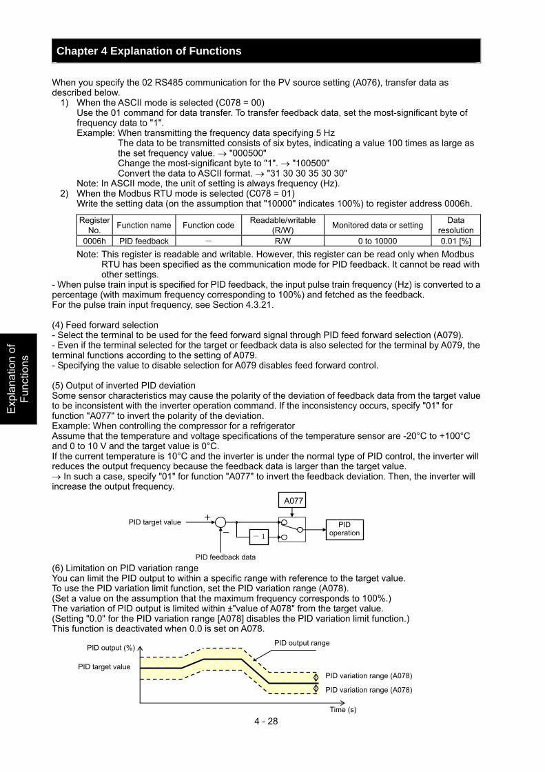
Chapter 4 Explanation of Functions
4 - 28
Exp
lana
tion
of
Func
tions
When you specify the 02 RS485 communication for the PV source setting (A076), transfer data as described below.
1) When the ASCII mode is selected (C078 = 00) Use the 01 command for data transfer. To transfer feedback data, set the most-significant byte of
frequency data to "1". Example: When transmitting the frequency data specifying 5 Hz The data to be transmitted consists of six bytes, indicating a value 100 times as large as
the set frequency value. → "000500" Change the most-significant byte to "1". → "100500" Convert the data to ASCII format. → "31 30 30 35 30 30"
Note: In ASCII mode, the unit of setting is always frequency (Hz). 2) When the Modbus RTU mode is selected (C078 = 01) Write the setting data (on the assumption that "10000" indicates 100%) to register address 0006h.
Register No. Function name Function code Readable/writable
(R/W) Monitored data or setting Data resolution
0006h PID feedback - R/W 0 to 10000 0.01 [%] Note: This register is readable and writable. However, this register can be read only when Modbus
RTU has been specified as the communication mode for PID feedback. It cannot be read with other settings.
- When pulse train input is specified for PID feedback, the input pulse train frequency (Hz) is converted to a percentage (with maximum frequency corresponding to 100%) and fetched as the feedback. For the pulse train input frequency, see Section 4.3.21. (4) Feed forward selection - Select the terminal to be used for the feed forward signal through PID feed forward selection (A079). - Even if the terminal selected for the target or feedback data is also selected for the terminal by A079, the terminal functions according to the setting of A079. - Specifying the value to disable selection for A079 disables feed forward control. (5) Output of inverted PID deviation Some sensor characteristics may cause the polarity of the deviation of feedback data from the target value to be inconsistent with the inverter operation command. If the inconsistency occurs, specify "01" for function "A077" to invert the polarity of the deviation. Example: When controlling the compressor for a refrigerator Assume that the temperature and voltage specifications of the temperature sensor are -20°C to +100°C and 0 to 10 V and the target value is 0°C. If the current temperature is 10°C and the inverter is under the normal type of PID control, the inverter will reduces the output frequency because the feedback data is larger than the target value. → In such a case, specify "01" for function "A077" to invert the feedback deviation. Then, the inverter will increase the output frequency.
(6) Limitation on PID variation range You can limit the PID output to within a specific range with reference to the target value. To use the PID variation limit function, set the PID variation range (A078). (Set a value on the assumption that the maximum frequency corresponds to 100%.) The variation of PID output is limited within ±"value of A078" from the target value. (Setting "0.0" for the PID variation range [A078] disables the PID variation limit function.) This function is deactivated when 0.0 is set on A078.
PID operation -1
A077
PID target value
PID feedback data
PID output (%)
PID target value
PID output range
PID variation range (A078)
PID variation range (A078)
Time (s)

Chapter 4 Explanation of Functions
4 - 29
Explanation of Functions
(7) Output of inverted PID deviation If the inverter is under the normal PID control and the PID operation result is a negative value, the frequency command to the inverter will be limited to 0 Hz. However, when "02" (enabling the inverted output) is set for the PID Function Enable (A071), the PID operation result to be output to the inverter is inverted if the result is a negative value. Setting "02" for function "A071" disables the PID variation limit (A078) described above. (8) PID gain adjustment If the inverter response is unsteady when the PID control function is used, try to adjust gain settings as follows: - If the feedback data does not quickly follow the change in the target value → Increase the P gain (A072). - If the feedback data is unstable although it quickly follows the change in the target value → Reduce the
P gain (A072). - If considerable time is required until the feedback data matches the target value → Reduce the I gain
(A073). - If the feedback data fluctuates unsteadily → Increase the I gain (A073). - If the inverter response is slow even after the P gain is increased → Increase the D gain (A074). - If the feedback data becomes fluctuant and unsteady when the P gain is increased → Reduce the D gain
(A074). (9) Maximum PID deviation output (OD) You can set the PID deviation level (C044) for PID control. When the PID deviation (ε) exceeds the level set as the level "C044", the signal is output to an intelligent output terminal. A value from 0 to 100 can be set as the level "C044". The range of values corresponds to the range of target values from 0 to the maximum. To use this output function, assign function "04" (OD) to one of the terminal functions C021 to C025 or the alarm relay terminal function C026. (10) Feedback comparison signal A feedback comparison signal can be output to an intelligent output terminal when the PID feedback data exceeds the specified range. To use this signal output function, assign function "31" (FBV) to one of the terminal functions C021 to C025 or the alarm relay terminal function C026.
(11) Process variable (PV), PID feedback monitoring (d004) You can monitor the PID feedback data on the inverter. When you set a PV scale conversion with function "A075", the value to be displayed as the monitored data can be the product of the feedback data and the scale. "Monitored value" = "feedback data (%)" x " PV scale conversion (A075)" (12) Reset of PID integration (PIDC) This reset function clears the integral result of PID operation. To use this function, assign function "24" (PIDC) to one of the terminal functions C001 to C008. The integral result is cleared each time the PIDC terminal is turned on. Never turn on the PIDC terminal during the PID operation. Otherwise, the inverter may trip because of overcurrent. Be sure to disable the PID function before turning on the PIDC terminal.
FW
FBV
ON OFF
OFF ON
PID feedback
C052 (off level)
C053 (on level)
Time
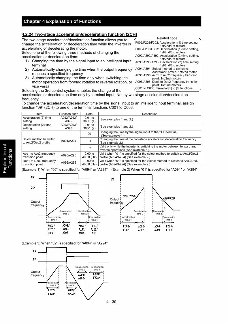
Chapter 4 Explanation of Functions
4 - 30
Exp
lana
tion
of
Func
tions
F002/F202/F302: Acceleration (1) time setting, 1st/2nd/3rd motors
F003/F203/F303: Deceleration (1) time setting, 1st/2nd/3rd motors
A092/A292/A392: Acceleration (2) time setting, 1st/2nd/3rd motors
A093/A293/A393: Deceleration (2) time setting, 1st/2nd/3rd motors
A094/A294: Select method to switch to Acc2/Dec2 profile, 1st/2nd motor
A095/A295: Acc1 to Acc2 frequency transition point, 1st/2nd motors
A096/A296: Dec1 to Dec2 frequency transition point, 1st/2nd motors
C001 to C008: Terminal [1] to [8] functions
Related code
4.2.24 Two-stage acceleration/deceleration function (2CH) The two-stage acceleration/deceleration function allows you to change the acceleration or deceleration time while the inverter is accelerating or decelerating the motor. Select one of the following three methods of changing the acceleration or deceleration time:
1) Changing the time by the signal input to an intelligent input terminal
2) Automatically changing the time when the output frequency reaches a specified frequency
3) Automatically changing the time only when switching the motor operation from forward rotation to reverse rotation, or vice versa
Selecting the 3rd control system enables the change of the acceleration or deceleration time only by terminal input. Not bytwo-stage acceleration/deceleration frequency. To change the acceleration/deceleration time by the signal input to an intelligent input terminal, assign function "09" (2CH) to one of the terminal functions C001 to C008.
Item Function code Data Description Acceleration (2) time setting
A092/A292/ A392
0.01 to 3600. (s) (See examples 1 and 2.)
Deceleration (2) time setting
A093/A293/ A393
0.01 to 3600. (s) (See examples 1 and 2.)
00 Changing the time by the signal input to the 2CH terminal (See example 1.)
01 Changing the time at the two-stage acceleration/deceleration frequency (See example 2.)
Select method to switch to Acc2/Dec2 profile A094/A294
02 Valid only while the inverter is switching the motor between forward and reverse operations (See example 3.)
Acc1 to Acc2 frequency transition point A095/A295 0.00 to
400.0 (Hz)Valid when "01" is specified for the select method to switch to Acc2/Dec2 profile (A094/A294) (See example 2.)
Dec1 to Dec2 frequency transition point A096/A296 0.00 to
400.0 (Hz)Valid when "01" is specified for the Select method to switch to Acc2/Dec2 profile (A094/A294) (See example 2.)
(Example 1) When "00" is specified for "A094" or "A294" (Example 2) When "01" is specified for "A094" or "A294" (Example 3) When "02" is specified for "A094" or "A294"
Output frequency
Output frequency
Output frequency
Acceleration time 1
Acceleration time 2
Deceleration time 2
Deceleration time 1
Acceleration time 1
Acceleration time 2
Deceleration time 2
Deceleration time 1
Acceleration time 1
Deceleration time 2
Acceleration time 2
Deceleration time 1
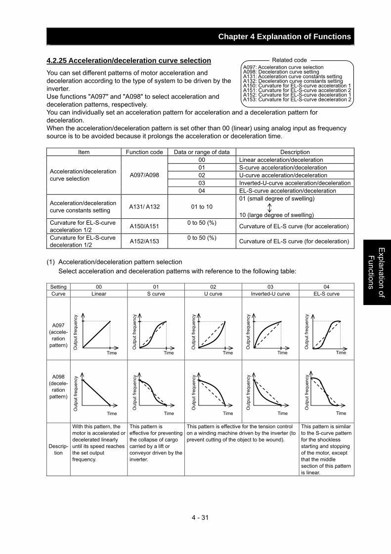
Chapter 4 Explanation of Functions
4 - 31
Explanation of Functions
4.2.25 Acceleration/deceleration curve selection You can set different patterns of motor acceleration and deceleration according to the type of system to be driven by the inverter. Use functions "A097" and "A098" to select acceleration and deceleration patterns, respectively. You can individually set an acceleration pattern for acceleration and a deceleration pattern for deceleration. When the acceleration/deceleration pattern is set other than 00 (linear) using analog input as frequency source is to be avoided because it prolongs the acceleration or deceleration time.
Item Function code Data or range of data Description 00 Linear acceleration/deceleration 01 S-curve acceleration/deceleration 02 U-curve acceleration/deceleration 03 Inverted-U-curve acceleration/deceleration
Acceleration/deceleration curve selection A097/A098
04 EL-S-curve acceleration/deceleration
Acceleration/deceleration curve constants setting A131/ A132 01 to 10
01 (small degree of swelling) 10 (large degree of swelling)
Curvature for EL-S-curve acceleration 1/2 A150/A151 0 to 50 (%) Curvature of EL-S curve (for acceleration)
Curvature for EL-S-curve deceleration 1/2 A152/A153 0 to 50 (%) Curvature of EL-S curve (for deceleration)
(1) Acceleration/deceleration pattern selection Select acceleration and deceleration patterns with reference to the following table:
Setting 00 01 02 03 04 Curve Linear S curve U curve Inverted-U curve EL-S curve
A097 (accele-ration
pattern)
A098 (decele-
ration pattern)
Descrip- tion
With this pattern, the motor is accelerated or decelerated linearly until its speed reaches the set output frequency.
This pattern is effective for preventing the collapse of cargo carried by a lift or conveyor driven by the inverter.
This pattern is effective for the tension control on a winding machine driven by the inverter (to prevent cutting of the object to be wound).
This pattern is similar to the S-curve pattern for the shockless starting and stopping of the motor, except that the middle section of this pattern is linear.
Out
put f
requ
ency
Time
Out
put f
requ
ency
Time
Out
put f
requ
ency
Time
Out
put f
requ
ency
Time
Out
put f
requ
ency
Time
Out
put f
requ
ency
Time
Out
put f
requ
ency
Time
Out
put f
requ
ency
Time
Out
put f
requ
ency
Time
Out
put f
requ
ency
Time
Related code A097: Acceleration curve selectionA098: Deceleration curve setting A131: Acceleration curve constants setting A132: Deceleration curve constants setting A150: Curvature for EL-S-curve acceleration 1 A151: Curvature for EL-S-curve acceleration 2 A152: Curvature for EL-S-curve deceleration 1 A153: Curvature for EL-S-curve deceleration 2
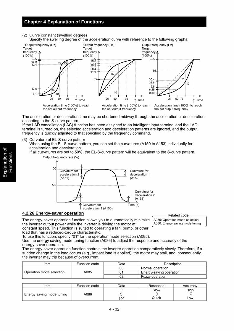
Chapter 4 Explanation of Functions
4 - 32
Exp
lana
tion
of
Func
tions
(2) Curve constant (swelling degree) Specify the swelling degree of the acceleration curve with reference to the following graphs:
The acceleration or deceleration time may be shortened midway through the acceleration or deceleration according to the S-curve pattern. If the LAD cancellation (LAC) function has been assigned to an intelligent input terminal and the LAC terminal is turned on, the selected acceleration and deceleration patterns are ignored, and the output frequency is quickly adjusted to that specified by the frequency command. (3) Curvature of EL-S-curve pattern When using the EL-S-curve pattern, you can set the curvatures (A150 to A153) individually for
acceleration and deceleration. If all curvatures are set to 50%, the EL-S-curve pattern will be equivalent to the S-curve pattern. 4.2.26 Energy-saver operation The energy-saver operation function allows you to automatically minimize the inverter output power while the inverter is driving the motor at constant speed. This function is suited to operating a fan, pump, or other load that has a reduced-torque characteristic. To use this function, specify "01" for the operation mode selection (A085). Use the energy saving mode tuning function (A086) to adjust the response and accuracy of the energy-saver operation. The energy-saver operation function controls the inverter operation comparatively slowly. Therefore, if a sudden change in the load occurs (e.g., impact load is applied), the motor may stall, and, consequently, the inverter may trip because of overcurrent.
Item Function code Data Description 00 Normal operation 01 Energy-saving operation Operation mode selection A085 02 Fuzzy operation
Item Function code Data Response Accuracy
Energy saving mode tuning A086 0
100
Slow
Quick
High
Low
96.9 82.4
17.6
3.1
25 50 75
10 02
10 02
99.6 93.8
35
25 50 75
10
10
02
87.5 68.4 64.6
65
35.4
0.39
25 50 75
10 02
31.612.56.25
Output frequency (Hz) Output frequency (Hz) Output frequency (Hz) Target frequency (100%)
Target frequency (100%)
Target frequency (100%)
Acceleration time (100%) to reach the set output frequency
Acceleration time (100%) to reach the set output frequency
Acceleration time (100%) to reach the set output frequency
Time Time Time
A085: Operation mode selection A086: Energy saving mode tuning
Related code
100
50
Time (s)
Output frequency rate (%)
Curvature for acceleration 2 (A151)
Curvature for deceleration 1 (A152)
Curvature for deceleration 2 (A153)
Curvature for acceleration 1 (A150)
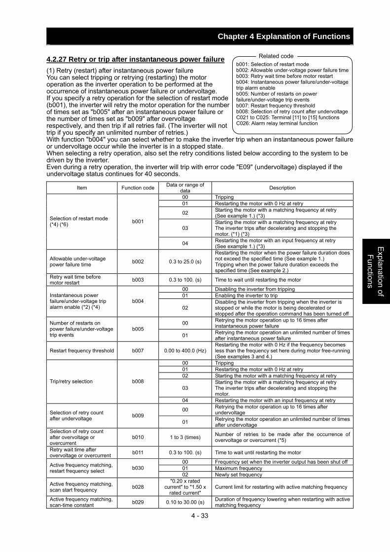
Chapter 4 Explanation of Functions
4 - 33
Explanation of Functions
4.2.27 Retry or trip after instantaneous power failure (1) Retry (restart) after instantaneous power failure You can select tripping or retrying (restarting) the motor operation as the inverter operation to be performed at the occurrence of instantaneous power failure or undervoltage. If you specify a retry operation for the selection of restart mode (b001), the inverter will retry the motor operation for the number of times set as "b005" after an instantaneous power failure or the number of times set as "b009" after overvoltage respectively, and then trip if all retries fail. (The inverter will not trip if you specify an unlimited number of retries.) With function "b004" you can select whether to make the inverter trip when an instantaneous power failure or undervoltage occur while the inverter is in a stopped state. When selecting a retry operation, also set the retry conditions listed below according to the system to be driven by the inverter. Even during a retry operation, the inverter will trip with error code "E09" (undervoltage) displayed if the undervoltage status continues for 40 seconds.
Item Function code Data or range of data Description
00 Tripping 01 Restarting the motor with 0 Hz at retry
02 Starting the motor with a matching frequency at retry (See example 1.) (*3)
03 Starting the motor with a matching frequency at retry The inverter trips after decelerating and stopping the motor. (*1) (*3)
Selection of restart mode (*4) (*6) b001
04 Restarting the motor with an input frequency at retry (See example 1.) (*3)
Allowable under-voltage power failure time b002 0.3 to 25.0 (s)
Restarting the motor when the power failure duration does not exceed the specified time (See example 1.) Tripping when the power failure duration exceeds the specified time (See example 2.)
Retry wait time before motor restart b003 0.3 to 100. (s) Time to wait until restarting the motor
00 Disabling the inverter from tripping 01 Enabling the inverter to trip Instantaneous power
failure/under-voltage trip alarm enable (*2) (*4)
b004 02
Disabling the inverter from tripping when the inverter is stopped or while the motor is being decelerated or stopped after the operation command has been turned off
00 Retrying the motor operation up to 16 times after instantaneous power failure Number of restarts on
power failure/under-voltage trip events
b005 01 Retrying the motor operation an unlimited number of times
after instantaneous power failure
Restart frequency threshold b007 0.00 to 400.0 (Hz)Restarting the motor with 0 Hz if the frequency becomes less than the frequency set here during motor free-running (See examples 3 and 4.)
00 Tripping 01 Restarting the motor with 0 Hz at retry 02 Starting the motor with a matching frequency at retry
03 Starting the motor with a matching frequency at retry The inverter trips after decelerating and stopping the motor.
Trip/retry selection b008
04 Restarting the motor with an input frequency at retry
00 Retrying the motor operation up to 16 times after undervoltage Selection of retry count
after undervoltage b009 01 Retrying the motor operation an unlimited number of times
after undervoltage Selection of retry count after overvoltage or overcurrent
b010 1 to 3 (times) Number of retries to be made after the occurrence of overvoltage or overcurrent (*5)
Retry wait time after overvoltage or overcurrent b011 0.3 to 100. (s) Time to wait until restarting the motor
00 Frequency set when the inverter output has been shut off01 Maximum frequency Active frequency matching,
restart frequency select b030 02 Newly set frequency
Active frequency matching, scan start frequency b028
"0.20 x rated current" to "1.50 x
rated current" Current limit for restarting with active matching frequency
Active frequency matching, scan-time constant b029 0.10 to 30.00 (s) Duration of frequency lowering when restarting with active
matching frequency
b001: Selection of restart mode b002: Allowable under-voltage power failure timeb003: Retry wait time before motor restart b004: Instantaneous power failure/under-voltage trip alarm enable b005: Number of restarts on power failure/under-voltage trip events b007: Restart frequency threshold b008: Selection of retry count after undervoltageC021 to C025: Terminal [11] to [15] functions C026: Alarm relay terminal function
Related code
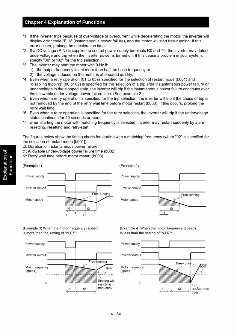
Chapter 4 Explanation of Functions
4 - 34
Exp
lana
tion
of
Func
tions
*1 If the inverter trips because of overvoltage or overcurrent while decelerating the motor, the inverter will display error code "E16" (instantaneous power failure), and the motor will start free-running. If this error occurs, prolong the deceleration time.
*2 If a DC voltage (P-N) is supplied to control power supply terminals R0 and T0, the inverter may detect undervoltage and trip when the inverter power is turned off. If this cause a problem in your system, specify "00" or "02" for the trip selection.
*3 The inverter may start the motor with 0 Hz if: 1) the output frequency is not more than half the base frequency or 2) the voltage induced on the motor is attenuated quickly.
*4 Even when a retry operation (01 to 03)is specified for the selection of restart mode (b001) and "disabling tripping" (00 or 02) is specified for the selection of a trip after instantaneous power failure or undervoltage in the stopped state, the inverter will trip if the instantaneous power failure continues over the allowable under-voltage power failure time. (See example 2.)
*5 Even when a retry operation is specified for the trip selection, the inverter will trip if the cause of trip is not removed by the end of the retry wait time before motor restart (b003). If this occurs, prolong the retry wait time.
*6 Even when a retry operation is specified for the retry selection, the inverter will trip if the undervoltage status continues for 40 seconds or more.
*7 when starting the motor with matching frequency is selected, inverter may restart suddenly by alarm resetting, resetting and retry-start.
The figures below show the timing charts for starting with a matching frequency (when "02" is specified for the selection of restart mode [b001]). t0: Duration of instantaneous power failure t1: Allowable under-voltage power failure time (b002) t2: Retry wait time before motor restart (b003) (Example 1) (Example 2)
0
t0 t2
b007
t0 t2 t1
Power supply
Inverter output
Motor speed
Free-running
t0 t1
Power supply
Inverter output
Motor speed Free-running
(Example 3) When the motor frequency (speed) is more than the setting of "b007":
Power supply
Inverter output
Motor frequency (speed)
Free-running
Starting with matching frequency
0
t0 t2
b007
(Example 4) When the motor frequency (speed) is less than the setting of "b007":
Power supply
Inverter output
Motor frequency (speed)
Free-running
Starting with 0 Hz
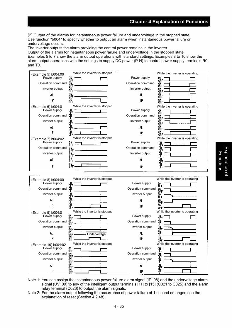
Chapter 4 Explanation of Functions
4 - 35
Explanation of Functions
(2) Output of the alarms for instantaneous power failure and undervoltage in the stopped state Use function "b004" to specify whether to output an alarm when instantaneous power failure or undervoltage occurs. The inverter outputs the alarm providing the control power remains in the inverter. Output of the alarms for instantaneous power failure and undervoltage in the stopped state Examples 5 to 7 show the alarm output operations with standard settings. Examples 8 to 10 show the alarm output operations with the settings to supply DC power (P-N) to control power supply terminals R0 and T0.
Note 1: You can assign the instantaneous power failure alarm signal (IP: 08) and the undervoltage alarm
signal (UV: 09) to any of the intelligent output terminals [11] to [15] (C021 to C025) and the alarm relay terminal (C026) to output the alarm signals.
Note 2: For the alarm output following the occurrence of power failure of 1 second or longer, see the explanation of reset (Section 4.2.48).
(Example 5) b004:00 Power supply
Operation command
Inverter output
(Example 6) b004:01 Power supply
Operation command
Inverter output
(Example 7) b004:02 Power supply
Operation command
Inverter output
Power supply
Operation command
Inverter output
Power supply
Operation command
Inverter output
Power supply
Operation command
Inverter output
While the inverter is stopped While the inverter is operating
While the inverter is stopped While the inverter is operating
While the inverter is stopped While the inverter is operating
(Example 8) b004:00 Power supply
Operation command
Inverter output
While the inverter is stopped While the inverter is operating Power supply
Operation command
Inverter output
(Example 9) b004:01 Power supply
Operation command
Inverter output
While the inverter is stopped While the inverter is operating Power supply
Operation command
Inverter output
(Example 10) b004:02 Power supply
Operation command
Inverter output
While the inverter is stopped While the inverter is operating Power supply
Operation command
Inverter output
Undervoltage
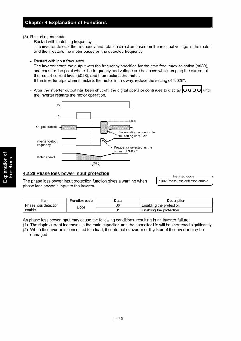
Chapter 4 Explanation of Functions
4 - 36
Exp
lana
tion
of
Func
tions
(3) Restarting methods - Restart with matching frequency The inverter detects the frequency and rotation direction based on the residual voltage in the motor,
and then restarts the motor based on the detected frequency. - Restart with input frequency The inverter starts the output with the frequency specified for the start frequency selection (b030),
searches for the point where the frequency and voltage are balanced while keeping the current at the restart current level (b028), and then restarts the motor.
If the inverter trips when it restarts the motor in this way, reduce the setting of "b028". - After the inverter output has been shut off, the digital operator continues to display until
the inverter restarts the motor operation. 4.2.28 Phase loss power input protection The phase loss power input protection function gives a warning when phase loss power is input to the inverter.
Item Function code Data Description 00 Disabling the protection Phase loss detection
enable b006 01 Enabling the protection
An phase loss power input may cause the following conditions, resulting in an inverter failure: (1) The ripple current increases in the main capacitor, and the capacitor life will be shortened significantly. (2) When the inverter is connected to a load, the internal converter or thyristor of the inverter may be
damaged.
b006: Phase loss detection enable Related code
FW
FRS
b028
Output current
Inverter output frequency
Deceleration according to the setting of "b029"
Frequency selected as the setting of "b030"
b003
Motor speed
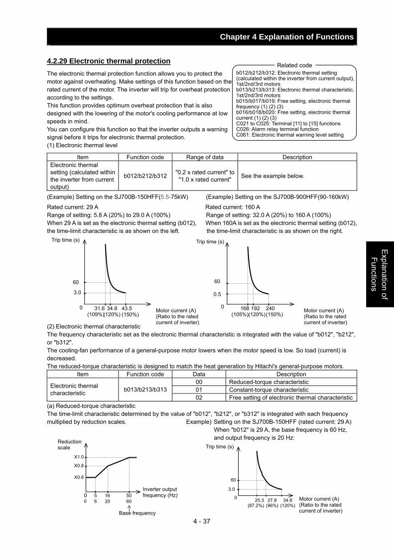
Chapter 4 Explanation of Functions
4 - 37
Explanation of Functions
4.2.29 Electronic thermal protection The electronic thermal protection function allows you to protect the motor against overheating. Make settings of this function based on the rated current of the motor. The inverter will trip for overheat protection according to the settings. This function provides optimum overheat protection that is also designed with the lowering of the motor's cooling performance at low speeds in mind. You can configure this function so that the inverter outputs a warning signal before it trips for electronic thermal protection. (1) Electronic thermal level
Item Function code Range of data Description Electronic thermal setting (calculated within the inverter from current output)
b012/b212/b312 "0.2 x rated current" to "1.0 x rated current" See the example below.
(Example) Setting on the SJ700B-150HFF(5.5-75kW) (Example) Setting on the SJ700B-900HFF(90-160kW)
Rated current: 29 A Rated current: 160 A Range of setting: 5.8 A (20%) to 29.0 A (100%) Range of setting: 32.0 A (20%) to 160 A (100%) When 29 A is set as the electronic thermal setting (b012), When 160A is set as the electronic thermal setting (b012), the time-limit characteristic is as shown on the left. the time-limit characteristic is as shown on the right. (2) Electronic thermal characteristic The frequency characteristic set as the electronic thermal characteristic is integrated with the value of "b012", "b212", or "b312". The cooling-fan performance of a general-purpose motor lowers when the motor speed is low. So load (current) is decreased. The reduced-torque characteristic is designed to match the heat generation by Hitachi's general-purpose motors.
Item Function code Data Description 00 Reduced-torque characteristic 01 Constant-torque characteristic Electronic thermal
characteristic b013/b213/b31302 Free setting of electronic thermal characteristic
(a) Reduced-torque characteristic The time-limit characteristic determined by the value of "b012", "b212", or "b312" is integrated with each frequency multiplied by reduction scales. Example) Setting on the SJ700B-150HFF (rated current: 29 A)
When "b012" is 29 A, the base frequency is 60 Hz, and output frequency is 20 Hz:
b012/b212/b312: Electronic thermal setting (calculated within the inverter from current output), 1st/2nd/3rd motors b013/b213/b313: Electronic thermal characteristic, 1st/2nd/3rd motors b015/b017/b019: Free setting, electronic thermal frequency (1) (2) (3) b016/b018/b020: Free setting, electronic thermal current (1) (2) (3) C021 to C025: Terminal [11] to [15] functions C026: Alarm relay terminal function C061: Electronic thermal warning level setting
Related code
Motor current (A)(Ratio to the rated current of inverter)
Trip time (s)
60
3.0
31.6(109%)
0 34.8(120%)
43.5 (150%)
25.3(87.2%)
27.8(96%)
34.8 (120%)
0
60
3.0
X1.0
5 16 50
X0.8
X0.6
0 6 20 60 0
Reduction scale
Inverter output frequency (Hz)
Base frequency
Trip time (s)
Motor current (A) (Ratio to the rated current of inverter)
Trip time (s)
Motor current (A)(Ratio to the rated current of inverter)
60
0.5
168(105%)
0 192 (120%)
240 (150%)
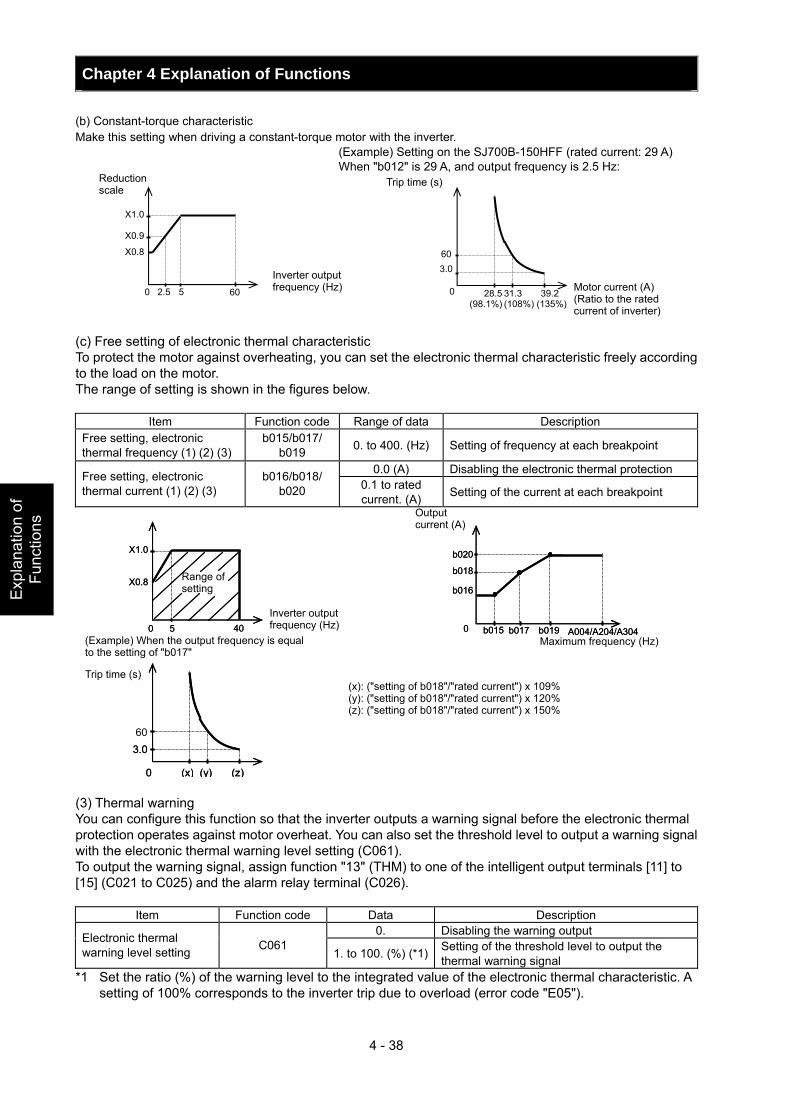
Chapter 4 Explanation of Functions
4 - 38
Exp
lana
tion
of
Func
tions
(b) Constant-torque characteristic Make this setting when driving a constant-torque motor with the inverter.
(Example) Setting on the SJ700B-150HFF (rated current: 29 A) When "b012" is 29 A, and output frequency is 2.5 Hz:
(c) Free setting of electronic thermal characteristic To protect the motor against overheating, you can set the electronic thermal characteristic freely according to the load on the motor. The range of setting is shown in the figures below.
Item Function code Range of data Description Free setting, electronic thermal frequency (1) (2) (3)
b015/b017/ b019 0. to 400. (Hz) Setting of frequency at each breakpoint
0.0 (A) Disabling the electronic thermal protection Free setting, electronic thermal current (1) (2) (3)
b016/b018/ b020 0.1 to rated
current. (A) Setting of the current at each breakpoint
(3) Thermal warning You can configure this function so that the inverter outputs a warning signal before the electronic thermal protection operates against motor overheat. You can also set the threshold level to output a warning signal with the electronic thermal warning level setting (C061). To output the warning signal, assign function "13" (THM) to one of the intelligent output terminals [11] to [15] (C021 to C025) and the alarm relay terminal (C026).
Item Function code Data Description 0. Disabling the warning output Electronic thermal
warning level setting C061 1. to 100. (%) (*1) Setting of the threshold level to output the
thermal warning signal *1 Set the ratio (%) of the warning level to the integrated value of the electronic thermal characteristic. A
setting of 100% corresponds to the inverter trip due to overload (error code "E05").
Inverter output frequency (Hz)
Range of setting
(Example) When the output frequency is equal to the setting of "b017"
(x): ("setting of b018"/"rated current") x 109% (y): ("setting of b018"/"rated current") x 120% (z): ("setting of b018"/"rated current") x 150%
Maximum frequency (Hz)
Trip time (s)
Output current (A)
X1.0
0 60
X0.9
X0.8
5 2.5 28.5(98.1%)
31.3 39.2 (108%) (135%)
60
0
Reduction scale
Inverter output frequency (Hz)
Trip time (s)
Motor current (A) (Ratio to the rated current of inverter)
3.0
A004/A204/A304
b020
b018
b016
b015 b017 b019 0
X1.0
5 40
X0.8
0
3.0
(x) (y) (z)0
A004/A204/A304
b020
b018
b016
b015 b017 b019 0
X1.0
5 40
X0.8
0
60 3.0
(x) (y) (z)0
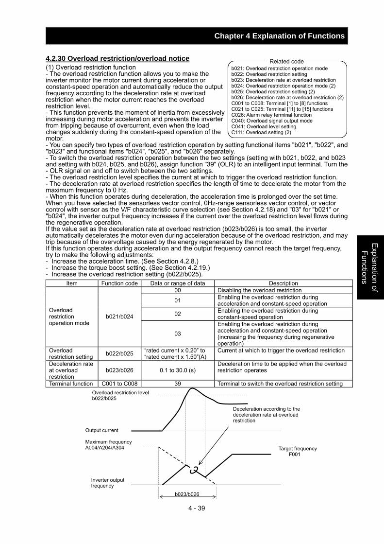
Chapter 4 Explanation of Functions
4 - 39
Explanation of Functions
4.2.30 Overload restriction/overload notice (1) Overload restriction function - The overload restriction function allows you to make the inverter monitor the motor current during acceleration or constant-speed operation and automatically reduce the output frequency according to the deceleration rate at overload restriction when the motor current reaches the overload restriction level. - This function prevents the moment of inertia from excessively increasing during motor acceleration and prevents the inverter from tripping because of overcurrent, even when the load changes suddenly during the constant-speed operation of the motor. - You can specify two types of overload restriction operation by setting functional items "b021", "b022", and "b023" and functional items "b024", "b025", and "b026" separately. - To switch the overload restriction operation between the two settings (setting with b021, b022, and b023 and setting with b024, b025, and b026), assign function "39" (OLR) to an intelligent input terminal. Turn the - OLR signal on and off to switch between the two settings. - The overload restriction level specifies the current at which to trigger the overload restriction function. - The deceleration rate at overload restriction specifies the length of time to decelerate the motor from the maximum frequency to 0 Hz. - When this function operates during deceleration, the acceleration time is prolonged over the set time. When you have selected the sensorless vector control, 0Hz-range sensorless vector control, or vector control with sensor as the V/F characteristic curve selection (see Section 4.2.18) and "03" for "b021" or "b024", the inverter output frequency increases if the current over the overload restriction level flows during the regenerative operation. If the value set as the deceleration rate at overload restriction (b023/b026) is too small, the inverter automatically decelerates the motor even during acceleration because of the overload restriction, and may trip because of the overvoltage caused by the energy regenerated by the motor. If this function operates during acceleration and the output frequency cannot reach the target frequency, try to make the following adjustments: - Increase the acceleration time. (See Section 4.2.8.) - Increase the torque boost setting. (See Section 4.2.19.) - Increase the overload restriction setting (b022/b025).
Item Function code Data or range of data Description 00 Disabling the overload restriction
01 Enabling the overload restriction during acceleration and constant-speed operation
02 Enabling the overload restriction during constant-speed operation
Overload restriction operation mode
b021/b024
03 Enabling the overload restriction during acceleration and constant-speed operation (increasing the frequency during regenerative operation)
Overload restriction setting b022/b025 “rated current x 0.20” to
“rated current x 1.50”(A) Current at which to trigger the overload restriction
Deceleration rate at overload restriction
b023/b026 0.1 to 30.0 (s) Deceleration time to be applied when the overload restriction operates
Terminal function C001 to C008 39 Terminal to switch the overload restriction setting
b021: Overload restriction operation mode b022: Overload restriction setting b023: Deceleration rate at overload restriction b024: Overload restriction operation mode (2) b025: Overload restriction setting (2) b026: Deceleration rate at overload restriction (2) C001 to C008: Terminal [1] to [8] functions C021 to C025: Terminal [11] to [15] functions C026: Alarm relay terminal function C040: Overload signal output mode C041: Overload level setting C111: Overload setting (2)
Related code
Overload restriction level b022/b025
Output current Maximum frequency A004/A204/A304
Inverter output frequency
Deceleration according to the deceleration rate at overload restriction
Target frequency F001
b023/b026
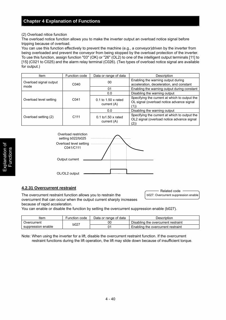
Chapter 4 Explanation of Functions
4 - 40
Exp
lana
tion
of
Func
tions
(2) Overload nitice function The overload notice function allows you to make the inverter output an overload notice signal before tripping because of overload. You can use this function effectively to prevent the machine (e.g., a conveyor)driven by the inverter from being overloaded and prevent the conveyor from being stopped by the overload protection of the inverter. To use this function, assign function "03" (OK) or "26" (OL2) to one of the intelligent output terminals [11] to [15] (C021 to C025) and the alarm relay terminal (C026). (Two types of overload notice signal are available for output.)
Item Function code Data or range of data Description
00 Enabling the warning output during acceleration, deceleration, and constant Overload signal output
mode C040 01 Enabling the warning output during constant0.0 Disabling the warning output
Overload level setting C041 0.1 to 1.50 x rated current (A)
Specifying the current at which to output the OL signal (overload notice advance signal (1))
0.0 Disabling the warning output
Overload setting (2) C111 0.1 to1.50 x rated current (A)
Specifying the current at which to output the OL2 signal (overload notice advance signal (2))
4.2.31 Overcurrent restraint The overcurrent restraint function allows you to restrain the overcurrent that can occur when the output current sharply increases because of rapid acceleration. You can enable or disable the function by setting the overcurrent suppression enable (b027).
Item Function code Data or range of data Description 00 Disabling the overcurrent restraint Overcurrent
suppression enable b027 01 Enabling the overcurrent restraint
Note: When using the inverter for a lift, disable the overcurrent restraint function. If the overcurrent
restraint functions during the lift operation, the lift may slide down because of insufficient torque.
Overload restriction setting b022/b025
Overload level setting C041/C111
Output current
OL/OL2 output
b027: Overcurrent suppression enable Related code
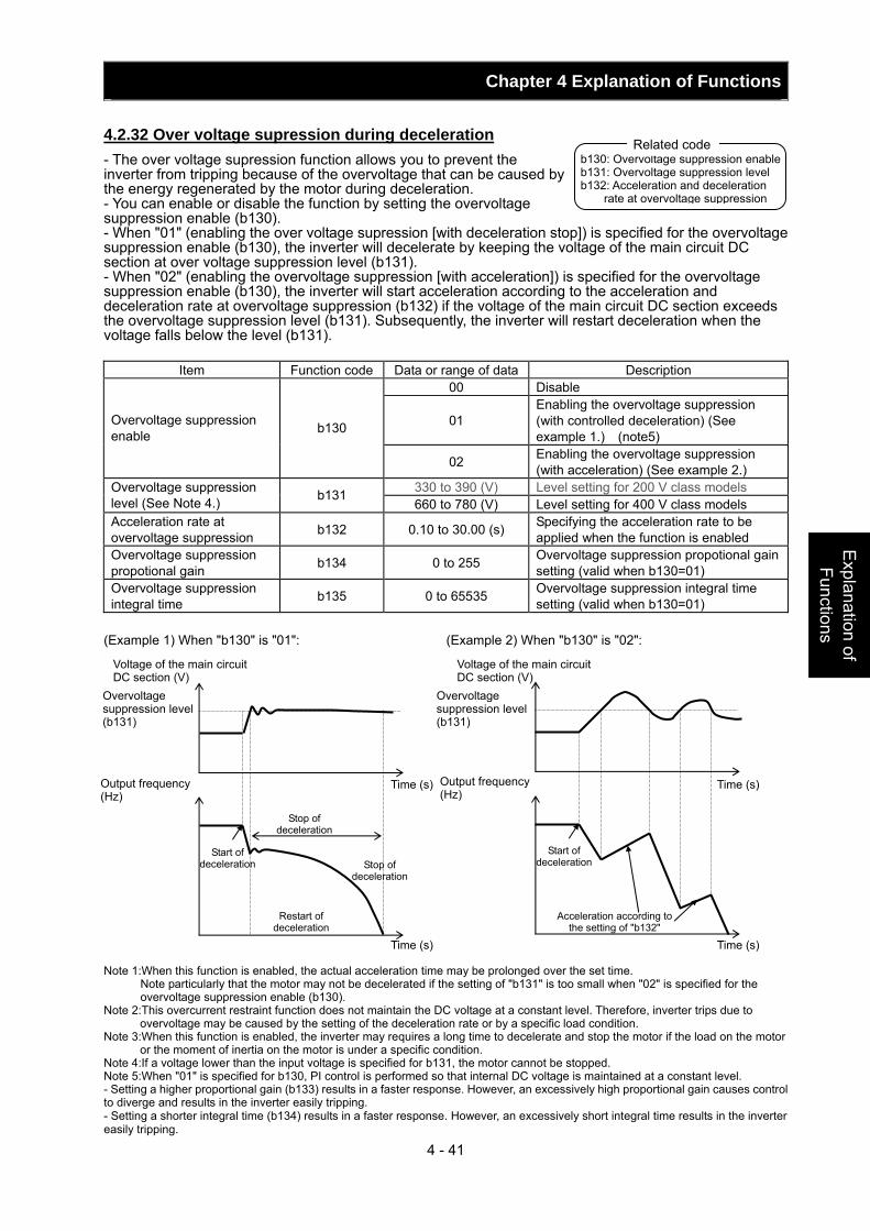
Chapter 4 Explanation of Functions
4 - 41
Explanation of Functions
4.2.32 Over voltage supression during deceleration - The over voltage supression function allows you to prevent the inverter from tripping because of the overvoltage that can be caused by the energy regenerated by the motor during deceleration. - You can enable or disable the function by setting the overvoltage suppression enable (b130). - When "01" (enabling the over voltage supression [with deceleration stop]) is specified for the overvoltage suppression enable (b130), the inverter will decelerate by keeping the voltage of the main circuit DC section at over voltage suppression level (b131). - When "02" (enabling the overvoltage suppression [with acceleration]) is specified for the overvoltage suppression enable (b130), the inverter will start acceleration according to the acceleration and deceleration rate at overvoltage suppression (b132) if the voltage of the main circuit DC section exceeds the overvoltage suppression level (b131). Subsequently, the inverter will restart deceleration when the voltage falls below the level (b131).
Item Function code Data or range of data Description 00 Disable
01 Enabling the overvoltage suppression (with controlled deceleration) (See example 1.) (note5)
Overvoltage suppression enable b130
02 Enabling the overvoltage suppression (with acceleration) (See example 2.)
330 to 390 (V) Level setting for 200 V class models Overvoltage suppression level (See Note 4.) b131
660 to 780 (V) Level setting for 400 V class models Acceleration rate at overvoltage suppression b132 0.10 to 30.00 (s) Specifying the acceleration rate to be
applied when the function is enabled Overvoltage suppression propotional gain b134 0 to 255 Overvoltage suppression propotional gain
setting (valid when b130=01) Overvoltage suppression integral time b135 0 to 65535 Overvoltage suppression integral time
setting (valid when b130=01) (Example 1) When "b130" is "01": (Example 2) When "b130" is "02": Note 1:When this function is enabled, the actual acceleration time may be prolonged over the set time.
Note particularly that the motor may not be decelerated if the setting of "b131" is too small when "02" is specified for the overvoltage suppression enable (b130).
Note 2:This overcurrent restraint function does not maintain the DC voltage at a constant level. Therefore, inverter trips due to overvoltage may be caused by the setting of the deceleration rate or by a specific load condition.
Note 3:When this function is enabled, the inverter may requires a long time to decelerate and stop the motor if the load on the motor or the moment of inertia on the motor is under a specific condition.
Note 4:If a voltage lower than the input voltage is specified for b131, the motor cannot be stopped. Note 5:When "01" is specified for b130, PI control is performed so that internal DC voltage is maintained at a constant level. - Setting a higher proportional gain (b133) results in a faster response. However, an excessively high proportional gain causes control to diverge and results in the inverter easily tripping. - Setting a shorter integral time (b134) results in a faster response. However, an excessively short integral time results in the inverter easily tripping.
b130: Overvoltage suppression enable b131: Overvoltage suppression level b132: Acceleration and deceleration
rate at overvoltage suppression
Related code
Voltage of the main circuit DC section (V)
Overvoltage suppression level (b131)
Output frequency (Hz)
Voltage of the main circuit DC section (V)
Overvoltage suppression level (b131)
Output frequency (Hz)
Start of deceleration
Stop of deceleration
Restart of deceleration
Stop of deceleration
Time (s)
Start of deceleration
Acceleration according to the setting of "b132"
Time (s)
Time (s) Time (s)
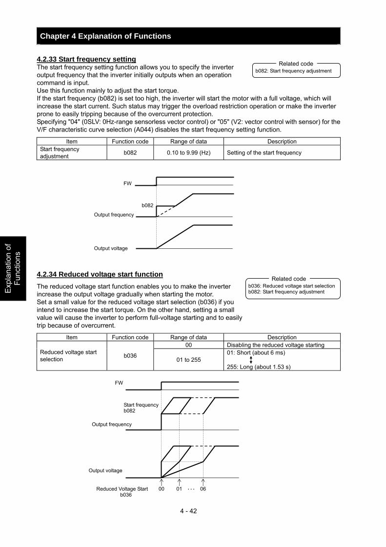
Chapter 4 Explanation of Functions
4 - 42
Exp
lana
tion
of
Func
tions
4.2.33 Start frequency setting The start frequency setting function allows you to specify the inverter output frequency that the inverter initially outputs when an operation command is input. Use this function mainly to adjust the start torque. If the start frequency (b082) is set too high, the inverter will start the motor with a full voltage, which will increase the start current. Such status may trigger the overload restriction operation or make the inverter prone to easily tripping because of the overcurrent protection. Specifying "04" (0SLV: 0Hz-range sensorless vector control) or "05" (V2: vector control with sensor) for the V/F characteristic curve selection (A044) disables the start frequency setting function.
Item Function code Range of data Description Start frequency adjustment b082 0.10 to 9.99 (Hz) Setting of the start frequency
4.2.34 Reduced voltage start function The reduced voltage start function enables you to make the inverter increase the output voltage gradually when starting the motor. Set a small value for the reduced voltage start selection (b036) if you intend to increase the start torque. On the other hand, setting a small value will cause the inverter to perform full-voltage starting and to easily trip because of overcurrent.
Item Function code Range of data Description 00 Disabling the reduced voltage starting
Reduced voltage start selection b036
01 to 255 01: Short (about 6 ms) 255: Long (about 1.53 s)
b082: Start frequency adjustment Related code
b036: Reduced voltage start selection b082: Start frequency adjustment
Related code
FW
Output frequency
Output voltage
b082
00 01 06・・・Reduced Voltage Start b036
Start frequency b082
FW
Output frequency
Output voltage
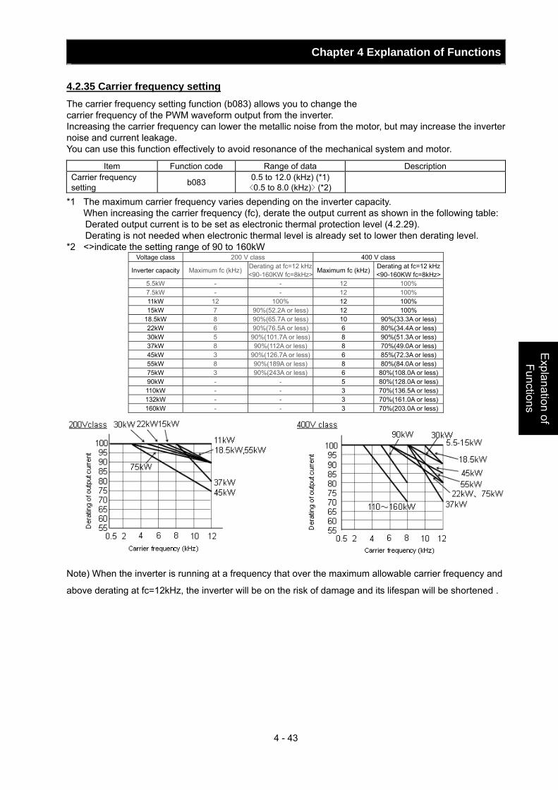
Chapter 4 Explanation of Functions
4 - 43
Explanation of Functions
4.2.35 Carrier frequency setting The carrier frequency setting function (b083) allows you to change the carrier frequency of the PWM waveform output from the inverter. Increasing the carrier frequency can lower the metallic noise from the motor, but may increase the inverter noise and current leakage. You can use this function effectively to avoid resonance of the mechanical system and motor.
Item Function code Range of data Description Carrier frequency setting b083 0.5 to 12.0 (kHz) (*1)
<0.5 to 8.0 (kHz)> (*2)
*1 The maximum carrier frequency varies depending on the inverter capacity. When increasing the carrier frequency (fc), derate the output current as shown in the following table: Derated output current is to be set as electronic thermal protection level (4.2.29). Derating is not needed when electronic thermal level is already set to lower then derating level. *2 <>indicate the setting range of 90 to 160kW
Voltage class 200 V class 400 V class
Inverter capacity Maximum fc (kHz) Derating at fc=12 kHz<90-160KW fc=8kHz> Maximum fc (kHz) Derating at fc=12 kHz
<90-160KW fc=8kHz> 5.5kW - - 12 100% 7.5kW - - 12 100% 11kW 12 100% 12 100% 15kW 7 90%(52.2A or less) 12 100%
18.5kW 8 90%(65.7A or less) 10 90%(33.3A or less) 22kW 6 90%(76.5A or less) 6 80%(34.4A or less) 30kW 5 90%(101.7A or less) 8 90%(51.3A or less) 37kW 8 90%(112A or less) 8 70%(49.0A or less) 45kW 3 90%(126.7A or less) 6 85%(72.3A or less) 55kW 8 90%(189A or less) 8 80%(84.0A or less) 75kW 3 90%(243A or less) 6 80%(108.0A or less) 90kW - - 5 80%(128.0A or less) 110kW - - 3 70%(136.5A or less) 132kW - - 3 70%(161.0A or less) 160kW - - 3 70%(203.0A or less)
Note) When the inverter is running at a frequency that over the maximum allowable carrier frequency and
above derating at fc=12kHz, the inverter will be on the risk of damage and its lifespan will be shortened .
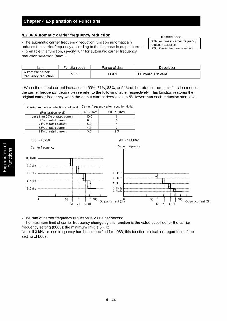
Chapter 4 Explanation of Functions
4 - 44
Exp
lana
tion
of
Func
tions
4.2.36 Automatic carrier frequency reduction - The automatic carrier frequency reduction function automatically reduces the carrier frequency according to the increase in output current. - To enable this function, specify "01" for automatic carrier frequency reduction selection (b089).
Item Function code Range of data Description Automatic carrier frequency reduction b089 00/01 00: invalid, 01: valid
- When the output current increases to 60%, 71%, 83%, or 91% of the rated current, this function reduces the carrier frequency, details please refer to the following table. respectively. This function restores the original carrier frequency when the output current decreases to 5% lower than each reduction start level.
Carrier frequency after reduction (kHz)Carrier frequency reduction start level
(Restoration level) 5.5~75kW 90~160KW Less than 60% of rated current 10.0 6
60% of rated current 8.0 5 71% of rated current 6.0 4 83% of rated current 4.5 3 91% of rated current 3.0 2.5
5.5~75kW 90~160kW
- The rate of carrier frequency reduction is 2 kHz per second. - The maximum limit of carrier frequency change by this function is the value specified for the carrier frequency setting (b083); the minimum limit is 3 kHz. Note: If 3 kHz or less frequency has been specified for b083, this function is disabled regardless of the setting of b089.
b089: Automatic carrier frequency reduction selection b083: Carrier frequency setting
Related code
Carrier frequency Carrier frequency
Output current (%) Output current (%)
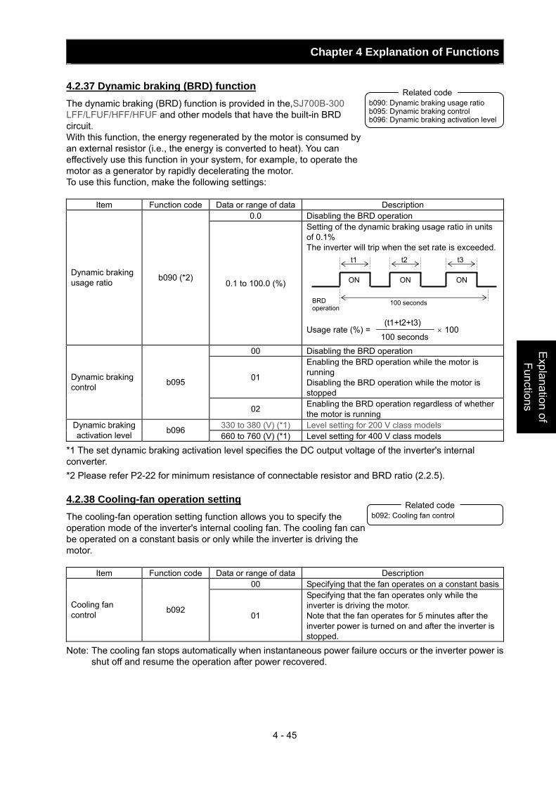
Chapter 4 Explanation of Functions
4 - 45
Explanation of Functions
4.2.37 Dynamic braking (BRD) function The dynamic braking (BRD) function is provided in the,SJ700B-300 LFF/LFUF/HFF/HFUF and other models that have the built-in BRD circuit. With this function, the energy regenerated by the motor is consumed by an external resistor (i.e., the energy is converted to heat). You can effectively use this function in your system, for example, to operate the motor as a generator by rapidly decelerating the motor. To use this function, make the following settings:
Item Function code Data or range of data Description 0.0 Disabling the BRD operation
Dynamic braking usage ratio b090 (*2)
0.1 to 100.0 (%)
Setting of the dynamic braking usage ratio in units of 0.1% The inverter will trip when the set rate is exceeded. Usage rate (%) = × 100
00 Disabling the BRD operation
01
Enabling the BRD operation while the motor is running Disabling the BRD operation while the motor is stopped
Dynamic braking control b095
02 Enabling the BRD operation regardless of whether the motor is running
330 to 380 (V) (*1) Level setting for 200 V class models Dynamic braking activation level b096
660 to 760 (V) (*1) Level setting for 400 V class models
*1 The set dynamic braking activation level specifies the DC output voltage of the inverter's internal converter. *2 Please refer P2-22 for minimum resistance of connectable resistor and BRD ratio (2.2.5). 4.2.38 Cooling-fan operation setting The cooling-fan operation setting function allows you to specify the operation mode of the inverter's internal cooling fan. The cooling fan can be operated on a constant basis or only while the inverter is driving the motor.
Item Function code Data or range of data Description 00 Specifying that the fan operates on a constant basis
Cooling fan control b092
01
Specifying that the fan operates only while the inverter is driving the motor. Note that the fan operates for 5 minutes after the inverter power is turned on and after the inverter is stopped.
Note: The cooling fan stops automatically when instantaneous power failure occurs or the inverter power is shut off and resume the operation after power recovered.
b090: Dynamic braking usage ratio b095: Dynamic braking control b096: Dynamic braking activation level
Related code
t2
ON
t1 t3
ON ON
BRD operation
100 seconds
100 seconds
(t1+t2+t3)
b092: Cooling fan control Related code
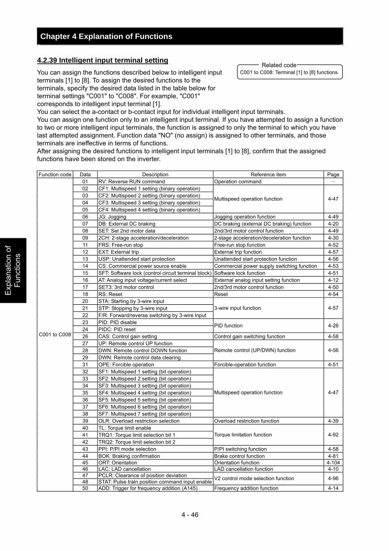
Chapter 4 Explanation of Functions
4 - 46
Exp
lana
tion
of
Func
tions
4.2.39 Intelligent input terminal setting You can assign the functions described below to intelligent input terminals [1] to [8]. To assign the desired functions to the terminals, specify the desired data listed in the table below for terminal settings "C001" to "C008". For example, "C001" corresponds to intelligent input terminal [1]. You can select the a-contact or b-contact input for individual intelligent input terminals. You can assign one function only to an intelligent input terminal. If you have attempted to assign a function to two or more intelligent input terminals, the function is assigned to only the terminal to which you have last attempted assignment. Function data "NO" (no assign) is assigned to other terminals, and those terminals are ineffective in terms of functions. After assigning the desired functions to intelligent input terminals [1] to [8], confirm that the assigned functions have been stored on the inverter. Function code Data Description Reference item Page
01 RV: Reverse RUN command Operation command - 02 CF1: Multispeed 1 setting (binary operation) 03 CF2: Multispeed 2 setting (binary operation) 04 CF3: Multispeed 3 setting (binary operation) 05 CF4: Multispeed 4 setting (binary operation)
Multispeed operation function 4-47
06 JG: Jogging Jogging operation function 4-4907 DB: External DC braking DC braking (external DC braking) function 4-2008 SET: Set 2nd motor data 2nd/3rd motor control function 4-4909 2CH: 2-stage acceleration/deceleration 2-stage acceleration/deceleration function 4-3011 FRS: Free-run stop Free-run stop function 4-5212 EXT: External trip External trip function 4-5713 USP: Unattended start protection Unattended start protection function 4-5614 CS: Commercial power source enable Commercial power supply switching function 4-5315 SFT: Software lock (control circuit terminal block) Software lock function 4-5116 AT: Analog input voltage/current select External analog input setting function 4-1217 SET3: 3rd motor control 2nd/3rd motor control function 4-5018 RS: Reset Reset 4-5420 STA: Starting by 3-wire input 21 STP: Stopping by 3-wire input 22 F/R: Forward/reverse switching by 3-wire input
3-wire input function 4-57
23 PID: PID disable 24 PIDC: PID reset
PID function 4-26
26 CAS: Control gain setting Control gain switching function 4-5827 UP: Remote control UP function 28 DWN: Remote control DOWN function 29 DWN: Remote control data clearing
Remote control (UP/DWN) function 4-56
31 OPE: Forcible operation Forcible-operation function 4-5132 SF1: Multispeed 1 setting (bit operation) 33 SF2: Multispeed 2 setting (bit operation) 34 SF3: Multispeed 3 setting (bit operation) 35 SF4: Multispeed 4 setting (bit operation) 36 SF5: Multispeed 5 setting (bit operation) 37 SF6: Multispeed 6 setting (bit operation) 38 SF7: Multispeed 7 setting (bit operation)
Multispeed operation function 4-47
39 OLR: Overload restriction selection Overload restriction function 4-3940 TL: Torque limit enable 41 TRQ1: Torque limit selection bit 1 42 TRQ2: Torque limit selection bit 2
Torque limitation function 4-92
43 PPI: P/PI mode selection P/PI switching function 4-5844 BOK: Braking confirmation Brake control function 4-8145 ORT: Orientation Orientation function 4-10446 LAC: LAD cancellation LAD cancellation function 4-1047 PCLR: Clearance of position deviation 48 STAT: Pulse train position command input enable V2 control mode selection function 4-96
C001 to C008
50 ADD: Trigger for frequency addition (A145) Frequency addition function 4-14
C001 to C008: Terminal [1] to [8] functions Related code
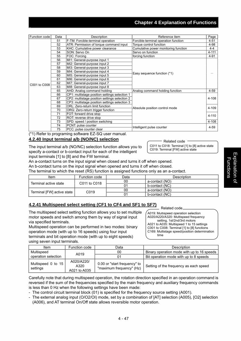
Chapter 4 Explanation of Functions
4 - 47
Explanation of Functions
Function code Data Description Reference item Page
51 F-TM: Forcible-terminal operation Forcible-terminal operation function 4-5152 ATR: Permission of torque command input Torque control function 4-9853 KHC: Cumulative power clearance Cumulative power monitoring function 4-454 SON: Servo On Servo on function 4-11155 FOC: Forcing forcing function 4-9156 MI1: General-purpose input 1 57 MI2: General-purpose input 2 58 MI3: General-purpose input 3 59 MI4: General-purpose input 4 60 MI5: General-purpose input 5 61 MI6: General-purpose input 6 62 MI7: General-purpose input 7 63 MI8: General-purpose input 8
Easy sequence function (*1) -
65 AHD: Analog command holding Analog command holding function 4-5966 CP1: multistage position settings selection 167 CP2: multistage position settings selection 268 CP3: multistage position settings selection 3
4-108
69 ORL: Zero-return limit function 70 ORG: Zero-return trigger function 4-109
71 FOT: forward drive stop 72 ROT: reverse drive stop 4-110
73 SPD: speed / position switching
Absolute position control mode
4-10874 PCNT: pulse counter
C001 to C008
75 PCC: pulse counter clear Intelligent pulse counter 4-59
(*1) Refer to programing software EZ-SQ user manual. 4.2.40 Input terminal a/b (NO/NC) selection The input terminal a/b (NO/NC) selection function allows you to specify a-contact or b-contact input for each of the intelligent input terminals [1] to [8] and the FW terminal. An a-contact turns on the input signal when closed and turns it off when opened. An b-contact turns on the input signal when opened and turns it off when closed. The terminal to which the reset (RS) function is assigned functions only as an a-contact.
Item Function code Data Description 00 a-contact (NO) Terminal active state C011 to C018 01 b-contact (NC) 00 a-contact (NO) Terminal [FW] active state C019 01 b-contact (NC)
4.2.41 Multispeed select setting (CF1 to CF4 and SF1 to SF7) The multispeed select setting function allows you to set multiple motor speeds and switch among them by way of signal input via specified terminals. Multispeed operation can be performed in two modes: binary operation mode (with up to 16 speeds) using four input terminals and bit operation mode (with up to eight speeds) using seven input terminals.
Item Function code Data Description 00 Binary operation mode with up to 16 speedsMultispeed
operation selection A019 01 Bit operation mode with up to 8 speeds
Multispeed 0 to 15 settings
A020/A220/ A320
A021 to A035
0.00 or "start frequency" to "maximum frequency" (Hz) Setting of the frequency as each speed
Carefully note that during multispeed operation, the rotation direction specified in an operation command is reversed if the sum of the frequencies specified by the main frequency and auxiliary frequency commands is less than 0 Hz when the following settings have been made: - The control circuit terminal block (01) is specified for the frequency source setting (A001). - The external analog input (O/O2/OI) mode, set by a combination of [AT] selection (A005), [O2] selection
(A006), and AT terminal On/Off state allows reversible motor operation.
C011 to C018: Terminal [1] to [8] active state C019: Terminal [FW] active state
Related code
A019: Multispeed operation selection A020/A220/A320: Multispeed frequency
setting, 1st/2nd/3rd motors A021 to A035: Multispeed 1 to 15 settings C001 to C008: Terminal [1] to [8] functions C169: Multistage speed/position determination
time
Related code
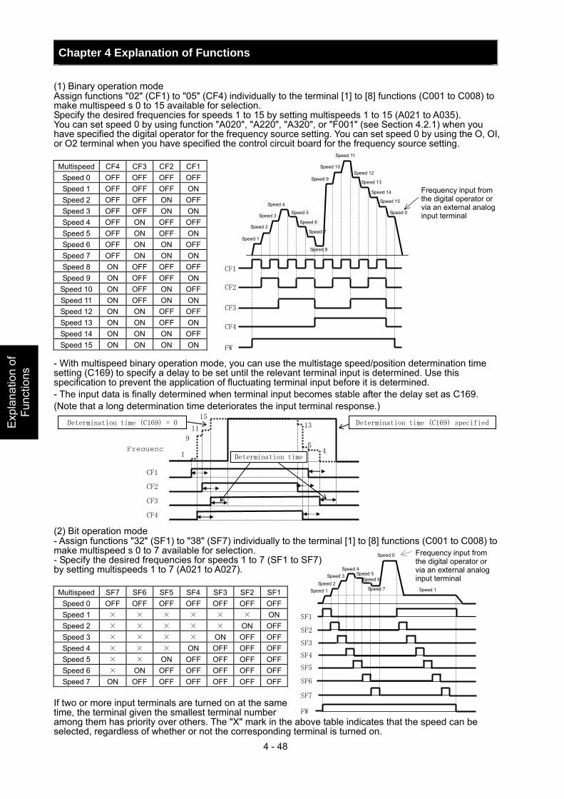
Chapter 4 Explanation of Functions
4 - 48
Exp
lana
tion
of
Func
tions
(1) Binary operation mode Assign functions "02" (CF1) to "05" (CF4) individually to the terminal [1] to [8] functions (C001 to C008) to make multispeed s 0 to 15 available for selection. Specify the desired frequencies for speeds 1 to 15 by setting multispeeds 1 to 15 (A021 to A035). You can set speed 0 by using function "A020", "A220", "A320", or "F001" (see Section 4.2.1) when you have specified the digital operator for the frequency source setting. You can set speed 0 by using the O, OI, or O2 terminal when you have specified the control circuit board for the frequency source setting.
Multispeed CF4 CF3 CF2 CF1 Speed 0 OFF OFF OFF OFF Speed 1 OFF OFF OFF ON Speed 2 OFF OFF ON OFF Speed 3 OFF OFF ON ON Speed 4 OFF ON OFF OFF Speed 5 OFF ON OFF ON Speed 6 OFF ON ON OFF Speed 7 OFF ON ON ON Speed 8 ON OFF OFF OFF Speed 9 ON OFF OFF ON
Speed 10 ON OFF ON OFF Speed 11 ON OFF ON ON Speed 12 ON ON OFF OFF Speed 13 ON ON OFF ON Speed 14 ON ON ON OFF Speed 15 ON ON ON ON
- With multispeed binary operation mode, you can use the multistage speed/position determination time setting (C169) to specify a delay to be set until the relevant terminal input is determined. Use this specification to prevent the application of fluctuating terminal input before it is determined. - The input data is finally determined when terminal input becomes stable after the delay set as C169. (Note that a long determination time deteriorates the input terminal response.) (2) Bit operation mode - Assign functions "32" (SF1) to "38" (SF7) individually to the terminal [1] to [8] functions (C001 to C008) to make multispeed s 0 to 7 available for selection. - Specify the desired frequencies for speeds 1 to 7 (SF1 to SF7) by setting multispeeds 1 to 7 (A021 to A027).
If two or more input terminals are turned on at the same time, the terminal given the smallest terminal number among them has priority over others. The "X" mark in the above table indicates that the speed can be selected, regardless of whether or not the corresponding terminal is turned on.
Multispeed SF7 SF6 SF5 SF4 SF3 SF2 SF1Speed 0 OFF OFF OFF OFF OFF OFF OFFSpeed 1 × × × × × × ONSpeed 2 × × × × × ON OFFSpeed 3 × × × × ON OFF OFFSpeed 4 × × × ON OFF OFF OFFSpeed 5 × × ON OFF OFF OFF OFFSpeed 6 × ON OFF OFF OFF OFF OFFSpeed 7 ON OFF OFF OFF OFF OFF OFF
CF4
FW
CF3
CF2
CF1
Speed 1
Speed 2
Speed 3
Speed 4
Speed 5
Speed 6
Speed 7
Speed 8
Speed 9
Speed 10
Speed 11
Speed 12
Speed 13
Speed 14
Speed 15
Speed 0
Frequency input from the digital operator or via an external analog input terminal
SF1
SF2
SF3
SF4
SF5
FW
SF6
SF7
Frequency input from the digital operator or via an external analog input terminal
Speed 1 Speed 2
Speed 3 Speed 4
Speed 5 Speed 6
Speed 7
Speed 0
Speed 1
Determination time
CF1
CF2
CF3
Frequenc
13
1 5
9
Determination time (C169) = 0 11
CF4
15 Determination time (C169) specified
4
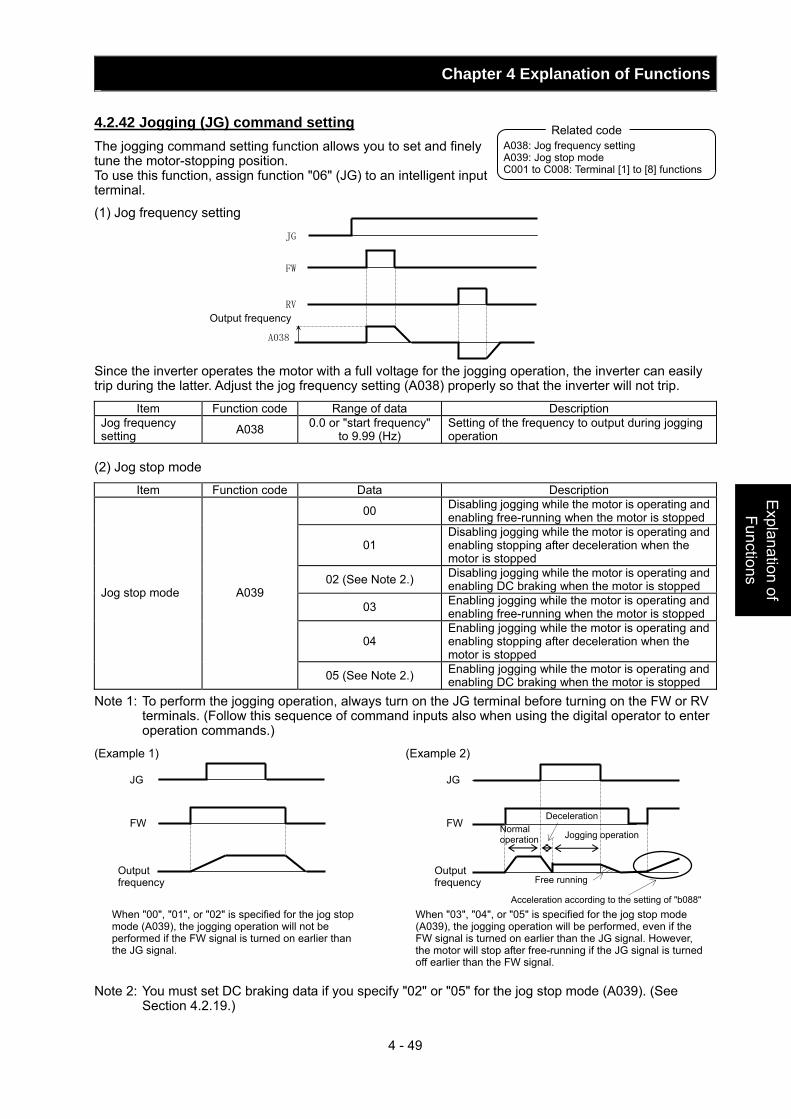
Chapter 4 Explanation of Functions
4 - 49
Explanation of Functions
4.2.42 Jogging (JG) command setting The jogging command setting function allows you to set and finely tune the motor-stopping position. To use this function, assign function "06" (JG) to an intelligent input terminal.
(1) Jog frequency setting Since the inverter operates the motor with a full voltage for the jogging operation, the inverter can easily trip during the latter. Adjust the jog frequency setting (A038) properly so that the inverter will not trip.
Item Function code Range of data Description Jog frequency setting A038 0.0 or "start frequency"
to 9.99 (Hz) Setting of the frequency to output during jogging operation
(2) Jog stop mode
Item Function code Data Description
00 Disabling jogging while the motor is operating and enabling free-running when the motor is stopped
01 Disabling jogging while the motor is operating and enabling stopping after deceleration when the motor is stopped
02 (See Note 2.) Disabling jogging while the motor is operating and enabling DC braking when the motor is stopped
03 Enabling jogging while the motor is operating and enabling free-running when the motor is stopped
04 Enabling jogging while the motor is operating and enabling stopping after deceleration when the motor is stopped
Jog stop mode A039
05 (See Note 2.) Enabling jogging while the motor is operating and enabling DC braking when the motor is stopped
Note 1: To perform the jogging operation, always turn on the JG terminal before turning on the FW or RV terminals. (Follow this sequence of command inputs also when using the digital operator to enter operation commands.)
(Example 1) (Example 2) Note 2: You must set DC braking data if you specify "02" or "05" for the jog stop mode (A039). (See
Section 4.2.19.)
Output frequency
A038: Jog frequency setting A039: Jog stop mode C001 to C008: Terminal [1] to [8] functions
Related code
JG
FW
RV
A038
Output frequency
Output frequency
FW
JG
FW
JG
When "00", "01", or "02" is specified for the jog stop mode (A039), the jogging operation will not be performed if the FW signal is turned on earlier than the JG signal.
When "03", "04", or "05" is specified for the jog stop mode (A039), the jogging operation will be performed, even if the FW signal is turned on earlier than the JG signal. However, the motor will stop after free-running if the JG signal is turned off earlier than the FW signal.
Normal operation
Deceleration
Free running
Jogging operation
Acceleration according to the setting of "b088"
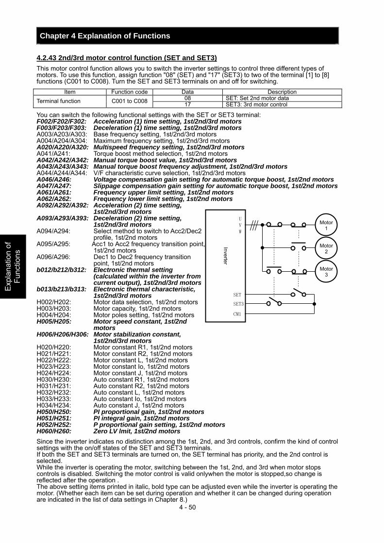
Chapter 4 Explanation of Functions
4 - 50
Exp
lana
tion
of
Func
tions
4.2.43 2nd/3rd motor control function (SET and SET3) This motor control function allows you to switch the inverter settings to control three different types of motors. To use this function, assign function "08" (SET) and "17" (SET3) to two of the terminal [1] to [8] functions (C001 to C008). Turn the SET and SET3 terminals on and off for switching.
Item Function code Data Description 08 SET: Set 2nd motor data Terminal function C001 to C008 17 SET3: 3rd motor control
You can switch the following functional settings with the SET or SET3 terminal: F002/F202/F302: Acceleration (1) time setting, 1st/2nd/3rd motors F003/F203/F303: Deceleration (1) time setting, 1st/2nd/3rd motors A003/A203/A303: Base frequency setting, 1st/2nd/3rd motors A004/A204/A304: Maximum frequency setting, 1st/2nd/3rd motors A020/A220/A320: Multispeed frequency setting, 1st/2nd/3rd motors A041/A241: Torque boost method selection, 1st/2nd motors A042/A242/A342: Manual torque boost value, 1st/2nd/3rd motors A043/A243/A343: Manual torque boost frequency adjustment, 1st/2nd/3rd motors A044/A244/A344: V/F characteristic curve selection, 1st/2nd/3rd motors A046/A246: Voltage compensation gain setting for automatic torque boost, 1st/2nd motors A047/A247: Slippage compensation gain setting for automatic torque boost, 1st/2nd motors A061/A261: Frequency upper limit setting, 1st/2nd motors A062/A262: Frequency lower limit setting, 1st/2nd motors A092/A292/A392: Acceleration (2) time setting,
1st/2nd/3rd motors A093/A293/A393: Deceleration (2) time setting,
1st/2nd/3rd motors A094/A294: Select method to switch to Acc2/Dec2
profile, 1st/2nd motors A095/A295: Acc1 to Acc2 frequency transition point,
1st/2nd motors A096/A296: Dec1 to Dec2 frequency transition
point, 1st/2nd motors b012/b212/b312: Electronic thermal setting
(calculated within the inverter from current output), 1st/2nd/3rd motors
b013/b213/b313: Electronic thermal characteristic, 1st/2nd/3rd motors
H002/H202: Motor data selection, 1st/2nd motors H003/H203: Motor capacity, 1st/2nd motors H004/H204: Motor poles setting, 1st/2nd motors H005/H205: Motor speed constant, 1st/2nd
motors H006/H206/H306: Motor stabilization constant,
1st/2nd/3rd motors H020/H220: Motor constant R1, 1st/2nd motors H021/H221: Motor constant R2, 1st/2nd motors H022/H222: Motor constant L, 1st/2nd motors H023/H223: Motor constant Io, 1st/2nd motors H024/H224: Motor constant J, 1st/2nd motors H030/H230: Auto constant R1, 1st/2nd motors H031/H231: Auto constant R2, 1st/2nd motors H032/H232: Auto constant L, 1st/2nd motors H033/H233: Auto constant Io, 1st/2nd motors H034/H234: Auto constant J, 1st/2nd motors H050/H250: PI proportional gain, 1st/2nd motors H051/H251: PI integral gain, 1st/2nd motors H052/H252: P proportional gain setting, 1st/2nd motors H060/H260: Zero LV lmit, 1st/2nd motors Since the inverter indicates no distinction among the 1st, 2nd, and 3rd controls, confirm the kind of control settings with the on/off states of the SET and SET3 terminals. If both the SET and SET3 terminals are turned on, the SET terminal has priority, and the 2nd control is selected. While the inverter is operating the motor, switching between the 1st, 2nd, and 3rd when motor stops controls is disabled. Switching the motor control is valid onlywhen the motor is stopped,so change is reflected after the operation . The above setting items printed in italic, bold type can be adjusted even while the inverter is operating the motor. (Whether each item can be set during operation and whether it can be changed during operation are indicated in the list of data settings in Chapter 8.)
Motor1
Motor2
Inverter
UV
W
SET
CM1
Motor3
SET3
Chapter 4 Explanation of Functions
4 - 51
Explanation of Functions
4.2.44 Software lock (SFT) function The software lock function allows you to specify whether to disable rewriting of the data set for functional items. Use this function to protect the data against accidental rewriting. You can select the functional items to be locked and the method of locking as described below. When using an intelligent input terminal for this function, assign function "15" (SFT) to one of the terminal [1] to [8] functions (C001 to C008).
Function code Data SFT terminal Description
00 ON/OFF Disabling rewriting of items other than "b031" (when SFT is on) or enabling rewriting (when SFT is off)
01 ON/OFF Disabling the rewriting of items other than "b031", "F001", "A020", "A220", "A320", "A021" to "A035", and "A038" (when SFT is on) or enabling rewriting (when SFT is off)
02 ― Disabling the rewriting of items other than "b031"
03 ― Disabling the rewriting of items other than "b031", "F001", "A020", "A220", "A320", "A021" to "A035", and "A038"
b031
10 ― Disabling rewriting except in the mode allowing changes during operation
4.2.45 Forcible-operation from digital operator (OPE) function The forcible-operation function allows you to forcibly enable the inverter operation from the digital operator when the digital operator is not selected as the device to input frequency and operation commands. An intelligent input terminal is used to turn this function on and off. When the intelligent input terminal to which the forcible-operation function is assigned is off, frequency and operation commands are input from the devices selected by functions "A001" and "A002". When the terminal is on, the device to input frequency and operation commands is forcibly switched to the digital operator. If the input device is switched while the inverter is operating, the current operation command is canceled and the inverter stops the output. When restarting the inverter operation, turn off the operation command that was to be entered from each input device for safety's sake, and then enter a new operation command.
Item Function code Data Description Terminal function C001 to C008 31 OPE: Forcible operation
4.2.46 Forcible-operation from terminal (F-TM) function The forcible-operation function allows you to forcibly enable the inverter operation via control circuit terminals when the control circuit terminal block is not selected as the device to input frequency and operation commands. An intelligent input terminal is used to turn this function on and off. When the intelligent input terminal to which the forcible-terminal operation function is assigned is off, frequency and operation commands are input from the devices selected by functions "A001" and "A002". When the terminal is on, the device to input frequency and operation commands is forcibly switched to the control circuit terminal block. If the input device is switched while the inverter is operating, the current operation command is canceled and the inverter stops the output. When restarting the inverter operation, turn off the operation command that was to be entered from each input device for safety's sake, and then enter a new operation command.
Item Function code Data Description Terminal function C001 to C008 51 F-TM: Forcible-terminal operation
b031: Software lock mode selection C001 to C008: Terminal [1] to [8] functions
Related code
A001: Frequency source setting A002: Run command source setting C001 to C008: Terminal [1] to [8] functions
Related code
A001: Frequency source setting A002: Run command source setting C001 to C008: Terminal [1] to [8] functions
Related code
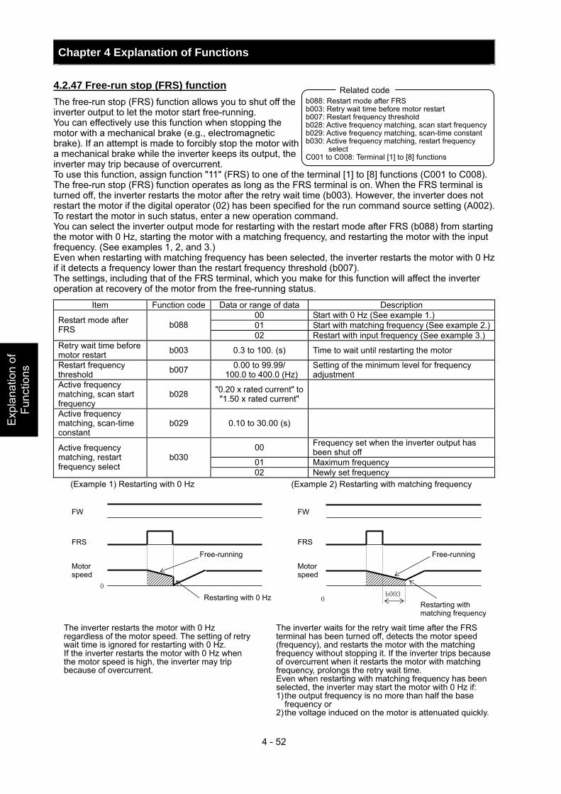
Chapter 4 Explanation of Functions
4 - 52
Exp
lana
tion
of
Func
tions
4.2.47 Free-run stop (FRS) function The free-run stop (FRS) function allows you to shut off the inverter output to let the motor start free-running. You can effectively use this function when stopping the motor with a mechanical brake (e.g., electromagnetic brake). If an attempt is made to forcibly stop the motor with a mechanical brake while the inverter keeps its output, the inverter may trip because of overcurrent. To use this function, assign function "11" (FRS) to one of the terminal [1] to [8] functions (C001 to C008). The free-run stop (FRS) function operates as long as the FRS terminal is on. When the FRS terminal is turned off, the inverter restarts the motor after the retry wait time (b003). However, the inverter does not restart the motor if the digital operator (02) has been specified for the run command source setting (A002). To restart the motor in such status, enter a new operation command. You can select the inverter output mode for restarting with the restart mode after FRS (b088) from starting the motor with 0 Hz, starting the motor with a matching frequency, and restarting the motor with the input frequency. (See examples 1, 2, and 3.) Even when restarting with matching frequency has been selected, the inverter restarts the motor with 0 Hz if it detects a frequency lower than the restart frequency threshold (b007). The settings, including that of the FRS terminal, which you make for this function will affect the inverter operation at recovery of the motor from the free-running status.
Item Function code Data or range of data Description 00 Start with 0 Hz (See example 1.) 01 Start with matching frequency (See example 2.)Restart mode after
FRS b088 02 Restart with input frequency (See example 3.)
Retry wait time before motor restart b003 0.3 to 100. (s) Time to wait until restarting the motor
Restart frequency threshold b007 0.00 to 99.99/
100.0 to 400.0 (Hz) Setting of the minimum level for frequency adjustment
Active frequency matching, scan start frequency
b028 "0.20 x rated current" to "1.50 x rated current"
Active frequency matching, scan-time constant
b029 0.10 to 30.00 (s)
00 Frequency set when the inverter output has been shut off
01 Maximum frequency
Active frequency matching, restart frequency select
b030
02 Newly set frequency (Example 1) Restarting with 0 Hz (Example 2) Restarting with matching frequency
b088: Restart mode after FRS b003: Retry wait time before motor restart b007: Restart frequency threshold b028: Active frequency matching, scan start frequency b029: Active frequency matching, scan-time constant b030: Active frequency matching, restart frequency
select C001 to C008: Terminal [1] to [8] functions
Related code
0
0b003
FW
Motor speed
FRS
FW
Motor speed
FRS Free-running Free-running
Restarting with 0 Hz Restarting with matching frequency
The inverter restarts the motor with 0 Hz regardless of the motor speed. The setting of retry wait time is ignored for restarting with 0 Hz. If the inverter restarts the motor with 0 Hz when the motor speed is high, the inverter may trip because of overcurrent.
The inverter waits for the retry wait time after the FRS terminal has been turned off, detects the motor speed (frequency), and restarts the motor with the matching frequency without stopping it. If the inverter trips because of overcurrent when it restarts the motor with matching frequency, prolongs the retry wait time. Even when restarting with matching frequency has been selected, the inverter may start the motor with 0 Hz if: 1) the output frequency is no more than half the base
frequency or 2) the voltage induced on the motor is attenuated quickly.
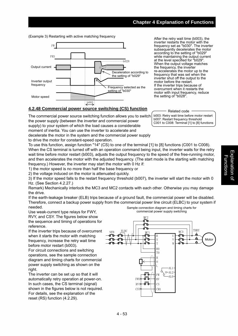
Chapter 4 Explanation of Functions
4 - 53
Explanation of Functions
(Example 3) Restarting with active matching frequency 4.2.48 Commercial power source switching (CS) function The commercial power source switching function allows you to switch the power supply (between the inverter and commercial power supply) to your system of which the load causes a considerable moment of inertia. You can use the inverter to accelerate and decelerate the motor in the system and the commercial power supply to drive the motor for constant-speed operation. To use this function, assign function "14" (CS) to one of the terminal [1] to [8] functions (C001 to C008). When the CS terminal is turned off with an operation command being input, the inverter waits for the retry wait time before motor restart (b003), adjusts the output frequency to the speed of the free-running motor, and then accelerates the motor with the adjusted frequency. (The start mode is the starting with matching frequency.) However, the inverter may start the motor with 0 Hz if: 1) the motor speed is no more than half the base frequency or 2) the voltage induced on the motor is attenuated quickly. 3) If the motor speed falls to the restart frequency threshold (b007), the inverter will start the motor with 0 Hz. (See Section 4.2.27.) Remark) Mechanically interlock the MC3 and MC2 contacts with each other. Otherwise you may damage the drive. If the earth-leakage breaker (ELB) trips because of a ground fault, the commercial power will be disabled. Therefore, connect a backup power supply from the commercial power line circuit (ELBC) to your system if needed. Use weak-current type relays for FWY, RVY, and CSY. The figures below show the sequence and timing of operations for reference. If the inverter trips because of overcurrent when it starts the motor with matching frequency, increase the retry wait time before motor restart (b003). For circuit connections and switching operations, see the sample connection diagram and timing charts for commercial power supply switching as shown on the right. The inverter can be set up so that it will automatically retry operation at power-on. In such cases, the CS terminal (signal) shown in the figures below is not required. For details, see the explanation of the reset (RS) function (4.2.29).
After the retry wait time (b003), the inverter restarts the motor with the frequency set as "b030". The inverter subsequently decelerates the motor according to the setting of "b029" while maintaining the output current at the level specified for "b029". When the output voltage matches the frequency, the inverter re-accelerates the motor up to the frequency that was set when the inverter shut off the output to the motor before the restart. If the inverter trips because of overcurrent when it restarts the motor with input frequency, reduce the setting of "b028".
b003: Retry wait time before motor restart b007: Restart frequency threshold C001 to C008: Terminal [1] to [8] functions
Related code
MotorRS
T
U V
W
O
L
FW
RV
CS
CM1
AL1
AL2
AL0
THRYMC1 MC3 ELBCNFB
FWY
RVY
CSY
MC2
H
R0T0
Sample connection diagram and timing charts for commercial power supply switching
FW
FRS
b028
Output current
Inverter output frequency
Deceleration according to the setting of "b029"
Frequency selected as the setting of "b030"
b003
Motor speed
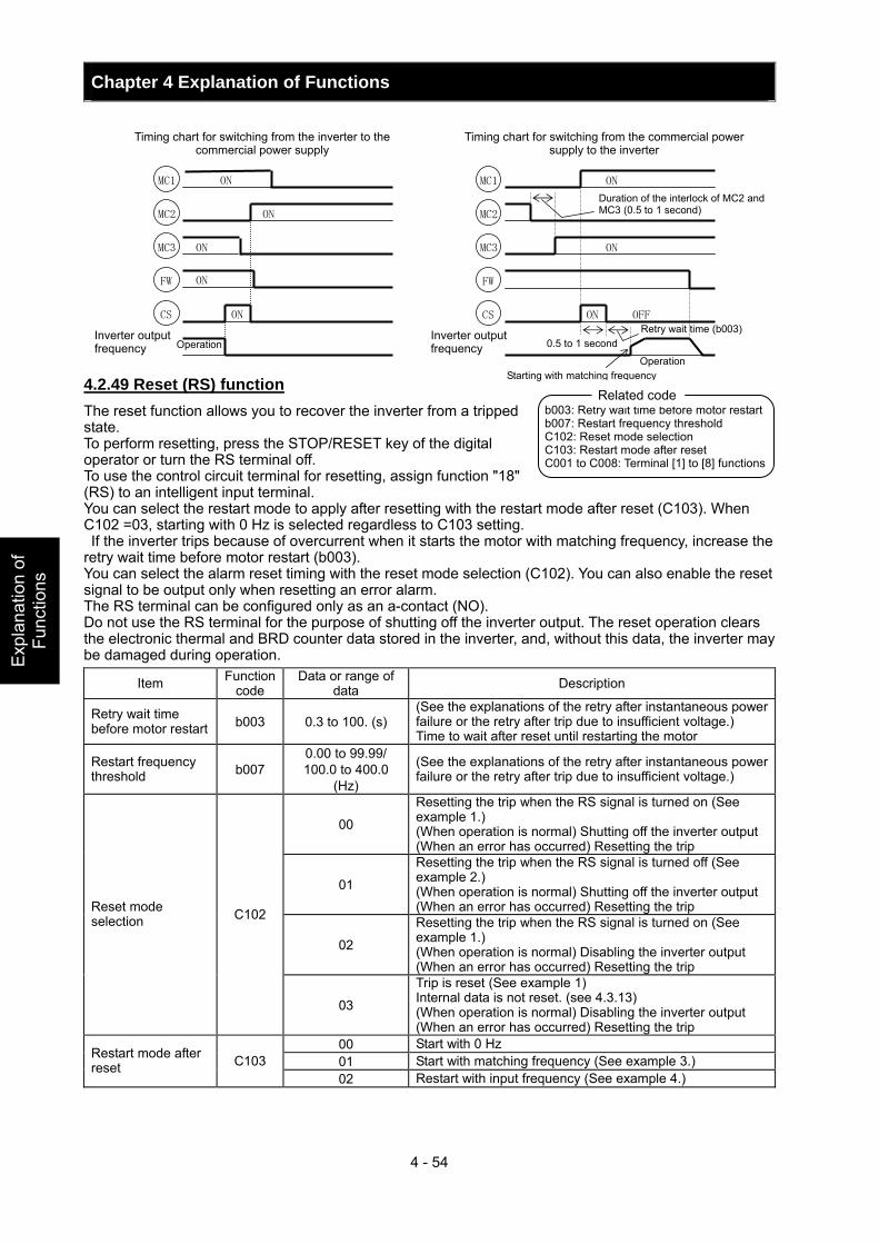
Chapter 4 Explanation of Functions
4 - 54
Exp
lana
tion
of
Func
tions
4.2.49 Reset (RS) function The reset function allows you to recover the inverter from a tripped state. To perform resetting, press the STOP/RESET key of the digital operator or turn the RS terminal off. To use the control circuit terminal for resetting, assign function "18" (RS) to an intelligent input terminal. You can select the restart mode to apply after resetting with the restart mode after reset (C103). When C102 =03, starting with 0 Hz is selected regardless to C103 setting. If the inverter trips because of overcurrent when it starts the motor with matching frequency, increase the retry wait time before motor restart (b003). You can select the alarm reset timing with the reset mode selection (C102). You can also enable the reset signal to be output only when resetting an error alarm. The RS terminal can be configured only as an a-contact (NO). Do not use the RS terminal for the purpose of shutting off the inverter output. The reset operation clears the electronic thermal and BRD counter data stored in the inverter, and, without this data, the inverter may be damaged during operation.
Item Function code
Data or range of data Description
Retry wait time before motor restart b003 0.3 to 100. (s)
(See the explanations of the retry after instantaneous power failure or the retry after trip due to insufficient voltage.) Time to wait after reset until restarting the motor
Restart frequency threshold b007
0.00 to 99.99/ 100.0 to 400.0
(Hz)
(See the explanations of the retry after instantaneous power failure or the retry after trip due to insufficient voltage.)
00
Resetting the trip when the RS signal is turned on (See example 1.) (When operation is normal) Shutting off the inverter output (When an error has occurred) Resetting the trip
01
Resetting the trip when the RS signal is turned off (See example 2.) (When operation is normal) Shutting off the inverter output (When an error has occurred) Resetting the trip
02
Resetting the trip when the RS signal is turned on (See example 1.) (When operation is normal) Disabling the inverter output (When an error has occurred) Resetting the trip
Reset mode selection C102
03
Trip is reset (See example 1) Internal data is not reset. (see 4.3.13) (When operation is normal) Disabling the inverter output (When an error has occurred) Resetting the trip
00 Start with 0 Hz 01 Start with matching frequency (See example 3.) Restart mode after
reset C103 02 Restart with input frequency (See example 4.)
ON
ON
MC1
MC2
MC3
FW
CS ON
ON
ON
MC1
MC2
MC3
FW
CS
ON
ON
ON OFF
Timing chart for switching from the inverter to the commercial power supply
Timing chart for switching from the commercial power supply to the inverter
Inverter output frequency Operation
Duration of the interlock of MC2 and MC3 (0.5 to 1 second)
0.5 to 1 second Inverter output frequency
Retry wait time (b003)
Starting with matching frequency Operation
b003: Retry wait time before motor restart b007: Restart frequency threshold C102: Reset mode selection C103: Restart mode after reset C001 to C008: Terminal [1] to [8] functions
Related code
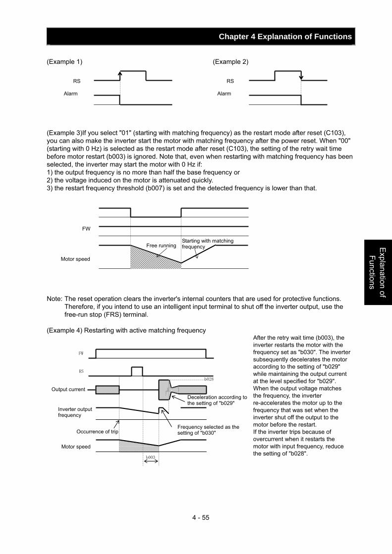
Chapter 4 Explanation of Functions
4 - 55
Explanation of Functions
(Example 1) (Example 2) (Example 3)If you select "01" (starting with matching frequency) as the restart mode after reset (C103), you can also make the inverter start the motor with matching frequency after the power reset. When "00" (starting with 0 Hz) is selected as the restart mode after reset (C103), the setting of the retry wait time before motor restart (b003) is ignored. Note that, even when restarting with matching frequency has been selected, the inverter may start the motor with 0 Hz if: 1) the output frequency is no more than half the base frequency or 2) the voltage induced on the motor is attenuated quickly. 3) the restart frequency threshold (b007) is set and the detected frequency is lower than that. Note: The reset operation clears the inverter's internal counters that are used for protective functions.
Therefore, if you intend to use an intelligent input terminal to shut off the inverter output, use the free-run stop (FRS) terminal.
(Example 4) Restarting with active matching frequency
Free running
RS
Alarm
RS
Alarm
FW
Motor speed
Starting with matching frequency
After the retry wait time (b003), the inverter restarts the motor with the frequency set as "b030". The inverter subsequently decelerates the motor according to the setting of "b029" while maintaining the output current at the level specified for "b029". When the output voltage matches the frequency, the inverter re-accelerates the motor up to the frequency that was set when the inverter shut off the output to the motor before the restart. If the inverter trips because of overcurrent when it restarts the motor with input frequency, reduce the setting of "b028".
Inverter output frequency
FW
RS
b003
b028
Motor speed
Occurrence of trip
Output current Deceleration according to the setting of "b029"
Frequency selected as the setting of "b030"
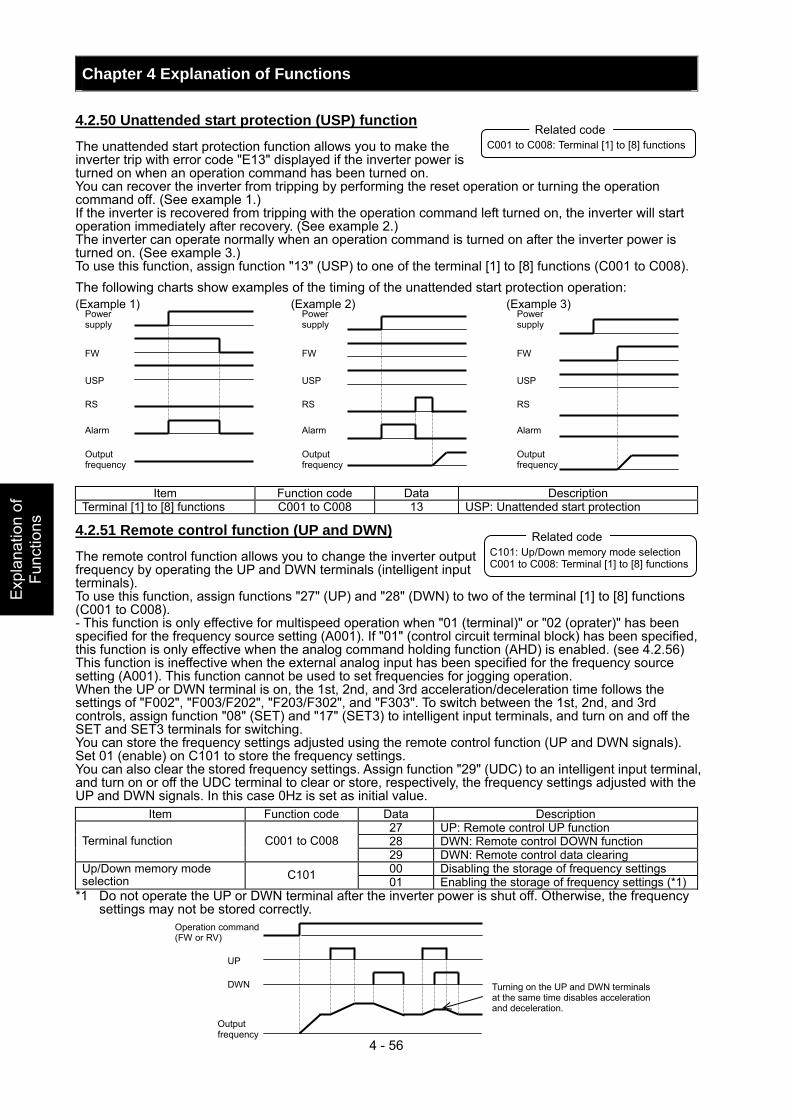
Chapter 4 Explanation of Functions
4 - 56
Exp
lana
tion
of
Func
tions
4.2.50 Unattended start protection (USP) function
The unattended start protection function allows you to make the inverter trip with error code "E13" displayed if the inverter power is turned on when an operation command has been turned on. You can recover the inverter from tripping by performing the reset operation or turning the operation command off. (See example 1.) If the inverter is recovered from tripping with the operation command left turned on, the inverter will start operation immediately after recovery. (See example 2.) The inverter can operate normally when an operation command is turned on after the inverter power is turned on. (See example 3.) To use this function, assign function "13" (USP) to one of the terminal [1] to [8] functions (C001 to C008). The following charts show examples of the timing of the unattended start protection operation: (Example 1) (Example 2) (Example 3)
Item Function code Data Description Terminal [1] to [8] functions C001 to C008 13 USP: Unattended start protection
4.2.51 Remote control function (UP and DWN)
The remote control function allows you to change the inverter output frequency by operating the UP and DWN terminals (intelligent input terminals). To use this function, assign functions "27" (UP) and "28" (DWN) to two of the terminal [1] to [8] functions (C001 to C008). - This function is only effective for multispeed operation when "01 (terminal)" or "02 (oprater)" has been specified for the frequency source setting (A001). If "01" (control circuit terminal block) has been specified, this function is only effective when the analog command holding function (AHD) is enabled. (see 4.2.56) This function is ineffective when the external analog input has been specified for the frequency source setting (A001). This function cannot be used to set frequencies for jogging operation. When the UP or DWN terminal is on, the 1st, 2nd, and 3rd acceleration/deceleration time follows the settings of "F002", "F003/F202", "F203/F302", and "F303". To switch between the 1st, 2nd, and 3rd controls, assign function "08" (SET) and "17" (SET3) to intelligent input terminals, and turn on and off the SET and SET3 terminals for switching. You can store the frequency settings adjusted using the remote control function (UP and DWN signals). Set 01 (enable) on C101 to store the frequency settings. You can also clear the stored frequency settings. Assign function "29" (UDC) to an intelligent input terminal, and turn on or off the UDC terminal to clear or store, respectively, the frequency settings adjusted with the UP and DWN signals. In this case 0Hz is set as initial value.
Item Function code Data Description 27 UP: Remote control UP function 28 DWN: Remote control DOWN function Terminal function C001 to C008 29 DWN: Remote control data clearing 00 Disabling the storage of frequency settings Up/Down memory mode
selection C101 01 Enabling the storage of frequency settings (*1)*1 Do not operate the UP or DWN terminal after the inverter power is shut off. Otherwise, the frequency
settings may not be stored correctly.
C001 to C008: Terminal [1] to [8] functions Related code
Power supply
FW
USP
RS
Alarm
Output frequency
C101: Up/Down memory mode selection C001 to C008: Terminal [1] to [8] functions
Related code
Power supply
FW
USP
RS
Alarm
Output frequency
Power supply
FW
USP
RS
Alarm
Output frequency
Operation command (FW or RV)
Turning on the UP and DWN terminals at the same time disables acceleration and deceleration.
Output frequency
UP
DWN
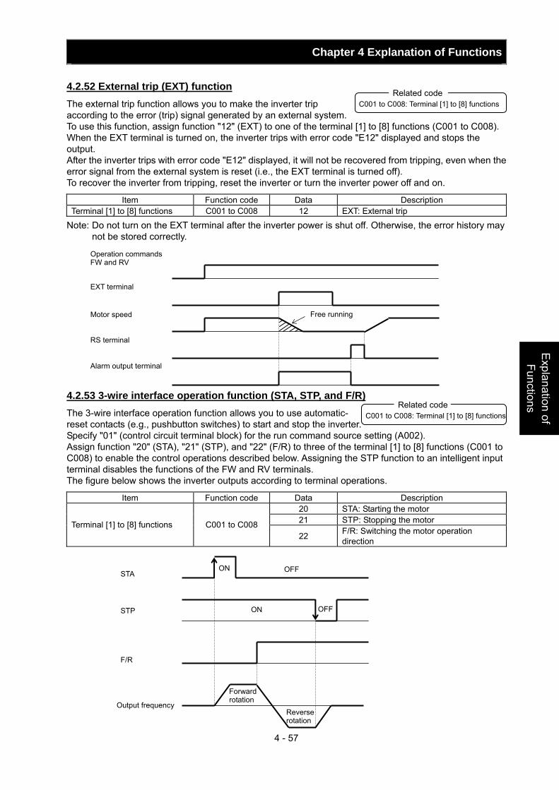
Chapter 4 Explanation of Functions
4 - 57
Explanation of Functions
4.2.52 External trip (EXT) function The external trip function allows you to make the inverter trip according to the error (trip) signal generated by an external system. To use this function, assign function "12" (EXT) to one of the terminal [1] to [8] functions (C001 to C008). When the EXT terminal is turned on, the inverter trips with error code "E12" displayed and stops the output. After the inverter trips with error code "E12" displayed, it will not be recovered from tripping, even when the error signal from the external system is reset (i.e., the EXT terminal is turned off). To recover the inverter from tripping, reset the inverter or turn the inverter power off and on.
Item Function code Data Description Terminal [1] to [8] functions C001 to C008 12 EXT: External trip
Note: Do not turn on the EXT terminal after the inverter power is shut off. Otherwise, the error history may not be stored correctly.
4.2.53 3-wire interface operation function (STA, STP, and F/R) The 3-wire interface operation function allows you to use automatic- reset contacts (e.g., pushbutton switches) to start and stop the inverter. Specify "01" (control circuit terminal block) for the run command source setting (A002). Assign function "20" (STA), "21" (STP), and "22" (F/R) to three of the terminal [1] to [8] functions (C001 to C008) to enable the control operations described below. Assigning the STP function to an intelligent input terminal disables the functions of the FW and RV terminals. The figure below shows the inverter outputs according to terminal operations.
Item Function code Data Description 20 STA: Starting the motor 21 STP: Stopping the motor Terminal [1] to [8] functions C001 to C008 22 F/R: Switching the motor operation
direction
C001 to C008: Terminal [1] to [8] functions Related code
Operation commands FW and RV
EXT terminal
Motor speed
RS terminal
Alarm output terminal
Free running
Output frequency
OFF
OFF
ON
ON
F/R
STP
STA
Forward rotation
Reverse rotation
C001 to C008: Terminal [1] to [8] functions Related code
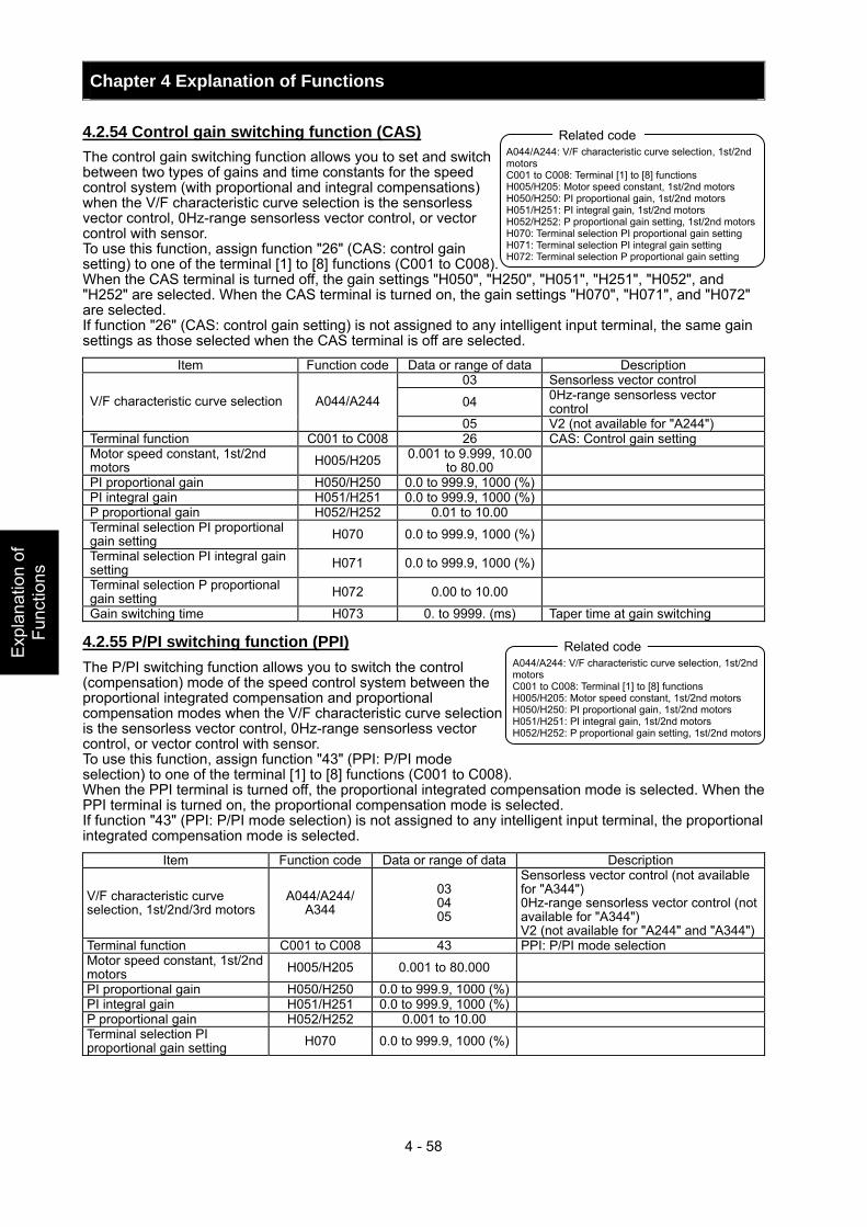
Chapter 4 Explanation of Functions
4 - 58
Exp
lana
tion
of
Func
tions
4.2.54 Control gain switching function (CAS) The control gain switching function allows you to set and switch between two types of gains and time constants for the speed control system (with proportional and integral compensations) when the V/F characteristic curve selection is the sensorless vector control, 0Hz-range sensorless vector control, or vector control with sensor. To use this function, assign function "26" (CAS: control gain setting) to one of the terminal [1] to [8] functions (C001 to C008). When the CAS terminal is turned off, the gain settings "H050", "H250", "H051", "H251", "H052", and "H252" are selected. When the CAS terminal is turned on, the gain settings "H070", "H071", and "H072" are selected. If function "26" (CAS: control gain setting) is not assigned to any intelligent input terminal, the same gain settings as those selected when the CAS terminal is off are selected.
Item Function code Data or range of data Description 03 Sensorless vector control
04 0Hz-range sensorless vector control V/F characteristic curve selection A044/A244
05 V2 (not available for "A244") Terminal function C001 to C008 26 CAS: Control gain setting Motor speed constant, 1st/2nd motors H005/H205 0.001 to 9.999, 10.00
to 80.00
PI proportional gain H050/H250 0.0 to 999.9, 1000 (%) PI integral gain H051/H251 0.0 to 999.9, 1000 (%) P proportional gain H052/H252 0.01 to 10.00 Terminal selection PI proportional gain setting H070 0.0 to 999.9, 1000 (%)
Terminal selection PI integral gain setting H071 0.0 to 999.9, 1000 (%)
Terminal selection P proportional gain setting H072 0.00 to 10.00
Gain switching time H073 0. to 9999. (ms) Taper time at gain switching
4.2.55 P/PI switching function (PPI) The P/PI switching function allows you to switch the control (compensation) mode of the speed control system between the proportional integrated compensation and proportional compensation modes when the V/F characteristic curve selection is the sensorless vector control, 0Hz-range sensorless vector control, or vector control with sensor. To use this function, assign function "43" (PPI: P/PI mode selection) to one of the terminal [1] to [8] functions (C001 to C008). When the PPI terminal is turned off, the proportional integrated compensation mode is selected. When the PPI terminal is turned on, the proportional compensation mode is selected. If function "43" (PPI: P/PI mode selection) is not assigned to any intelligent input terminal, the proportional integrated compensation mode is selected.
Item Function code Data or range of data Description
V/F characteristic curve selection, 1st/2nd/3rd motors
A044/A244/ A344
03 04 05
Sensorless vector control (not available for "A344") 0Hz-range sensorless vector control (not available for "A344") V2 (not available for "A244" and "A344")
Terminal function C001 to C008 43 PPI: P/PI mode selection Motor speed constant, 1st/2nd motors H005/H205 0.001 to 80.000
PI proportional gain H050/H250 0.0 to 999.9, 1000 (%) PI integral gain H051/H251 0.0 to 999.9, 1000 (%) P proportional gain H052/H252 0.001 to 10.00 Terminal selection PI proportional gain setting H070 0.0 to 999.9, 1000 (%)
A044/A244: V/F characteristic curve selection, 1st/2nd motors C001 to C008: Terminal [1] to [8] functions H005/H205: Motor speed constant, 1st/2nd motors H050/H250: PI proportional gain, 1st/2nd motors H051/H251: PI integral gain, 1st/2nd motors H052/H252: P proportional gain setting, 1st/2nd motors H070: Terminal selection PI proportional gain setting H071: Terminal selection PI integral gain setting H072: Terminal selection P proportional gain setting
Related code
A044/A244: V/F characteristic curve selection, 1st/2nd motors C001 to C008: Terminal [1] to [8] functions H005/H205: Motor speed constant, 1st/2nd motors H050/H250: PI proportional gain, 1st/2nd motors H051/H251: PI integral gain, 1st/2nd motors H052/H252: P proportional gain setting, 1st/2nd motors
Related code
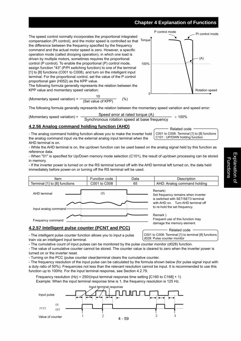
Chapter 4 Explanation of Functions
4 - 59
Explanation of Functions
The speed control normally incorporates the proportional integrated compensation (PI control), and the motor speed is controlled so that the difference between the frequency specified by the frequency command and the actual motor speed is zero. However, a specific operation mode (called drooping operation), in which one load is driven by multiple motors, sometimes requires the proportional control (P control). To enable the proportional (P) control mode, assign function "43" (P/PI switching function) to one of the terminal [1] to [8] functions (C001 to C008), and turn on the intelligent input terminal. For the proportional control, set the value of the P control proportional gain (H052) as the KPP value. The following formula generally represents the relation between the KPP value and momentary speed variation: (Momentary speed variation) = (%) The following formula generally represents the relation between the momentary speed variation and speed error: (Momentary speed variation) = × 100%
4.2.56 Analog command holding function (AHD) - The analog command holding function allows you to make the inverter hold the analog command input via the external analog input terminal when the AHD terminal is on. - While the AHD terminal is on, the up/down function can be used based on the analog signal held by this function as reference data. - When "01" is specified for Up/Down memory mode selection (C101), the result of up/down processing can be stored in memory. - If the inverter power is turned on or the RS terminal turned off with the AHD terminal left turned on, the data held immediately before power-on or turning off the RS terminal will be used.
Item Function code Data Description Terminal [1] to [8] functions C001 to C008 65 AHD: Analog command holding
4.2.57 Intelligent pulse counter (PCNT and PCC) - The intelligent pulse counter function allows you to input a pulse train via an intelligent input terminal. - The cumulative count of input pulses can be monitored by the pulse counter monitor (d028) function. - The value of cumulative counter cannot be stored. The counter value is cleared to zero when the inverter power is turned on or the inverter reset. - Turning on the PCC (pulse counter clear)terminal clears the cumulative counter. - The frequency resolution of the input pulse can be calculated by the formula shown below (for pulse signal input with a duty ratio of 50%). Frequencies not less than the relevant resolution cannot be input. It is recommended to use this function up to 100Hz. For the input terminal response, see Section 4.2.79.
Frequency resolution (Hz) = 250/(input terminal response time setting [C160 to C168] + 1) Example: When the input terminal response time is 1, the frequency resolution is 125 Hz.
P control mode PI control mode
100%
0
Torque
(A)
Rotation speed
10 (Set value of KPP)
Speed error at rated torque (A) Synchronous rotation speed at base frequency
C001 to C008: Terminal [1] to [8] functions C101 : UP/DWN holding function
Related code
ONAHD terminal
Input analog command
Frequency command
C001 to C008: Terminal [1] to terminal [8] functions d028: Pulse counter monitor
Related code
Input pulse
PCNT ON
OFF
Input terminal response
1 2 3 4 Value of counter
Remark) Set frequency remains when inverter is switched with SET/SET3 terminal with AHD on. Turn AHD terminal off to re-hold the set frequency. Remark ) Frequent use of this function may damage the memory element.
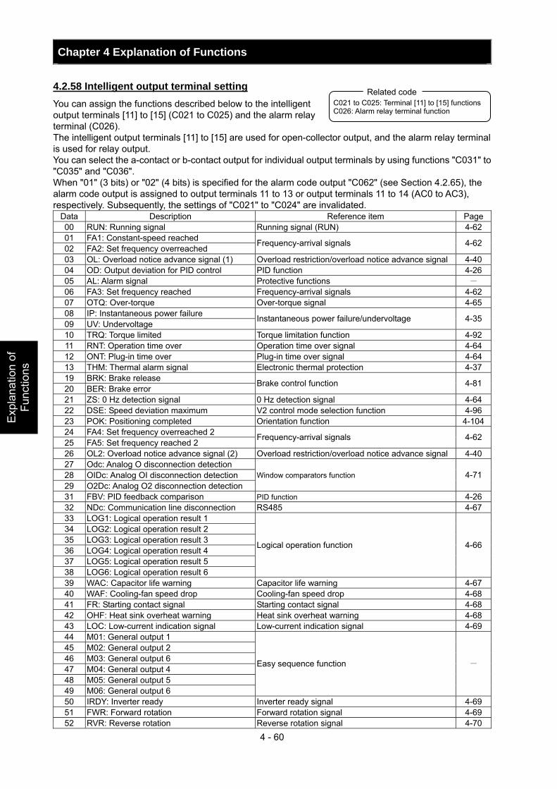
Chapter 4 Explanation of Functions
4 - 60
Exp
lana
tion
of
Func
tions
4.2.58 Intelligent output terminal setting You can assign the functions described below to the intelligent output terminals [11] to [15] (C021 to C025) and the alarm relay terminal (C026). The intelligent output terminals [11] to [15] are used for open-collector output, and the alarm relay terminal is used for relay output. You can select the a-contact or b-contact output for individual output terminals by using functions "C031" to "C035" and "C036". When "01" (3 bits) or "02" (4 bits) is specified for the alarm code output "C062" (see Section 4.2.65), the alarm code output is assigned to output terminals 11 to 13 or output terminals 11 to 14 (AC0 to AC3), respectively. Subsequently, the settings of "C021" to "C024" are invalidated.
Data Description Reference item Page00 RUN: Running signal Running signal (RUN) 4-62 01 FA1: Constant-speed reached 02 FA2: Set frequency overreached
Frequency-arrival signals 4-62
03 OL: Overload notice advance signal (1) Overload restriction/overload notice advance signal 4-40 04 OD: Output deviation for PID control PID function 4-26 05 AL: Alarm signal Protective functions - 06 FA3: Set frequency reached Frequency-arrival signals 4-62 07 OTQ: Over-torque Over-torque signal 4-65 08 IP: Instantaneous power failure 09 UV: Undervoltage
Instantaneous power failure/undervoltage 4-35
10 TRQ: Torque limited Torque limitation function 4-92 11 RNT: Operation time over Operation time over signal 4-64 12 ONT: Plug-in time over Plug-in time over signal 4-64 13 THM: Thermal alarm signal Electronic thermal protection 4-37 19 BRK: Brake release 20 BER: Brake error
Brake control function 4-81
21 ZS: 0 Hz detection signal 0 Hz detection signal 4-64 22 DSE: Speed deviation maximum V2 control mode selection function 4-96 23 POK: Positioning completed Orientation function 4-10424 FA4: Set frequency overreached 2 25 FA5: Set frequency reached 2
Frequency-arrival signals 4-62
26 OL2: Overload notice advance signal (2) Overload restriction/overload notice advance signal 4-40 27 Odc: Analog O disconnection detection 28 OIDc: Analog OI disconnection detection 29 O2Dc: Analog O2 disconnection detection
Window comparators function 4-71
31 FBV: PID feedback comparison PID function 4-26 32 NDc: Communication line disconnection RS485 4-67 33 LOG1: Logical operation result 1 34 LOG2: Logical operation result 2 35 LOG3: Logical operation result 3 36 LOG4: Logical operation result 4 37 LOG5: Logical operation result 5 38 LOG6: Logical operation result 6
Logical operation function 4-66
39 WAC: Capacitor life warning Capacitor life warning 4-67 40 WAF: Cooling-fan speed drop Cooling-fan speed drop 4-68 41 FR: Starting contact signal Starting contact signal 4-68 42 OHF: Heat sink overheat warning Heat sink overheat warning 4-68 43 LOC: Low-current indication signal Low-current indication signal 4-69 44 M01: General output 1 45 M02: General output 2 46 M03: General output 6 47 M04: General output 4 48 M05: General output 5 49 M06: General output 6
Easy sequence function -
50 IRDY: Inverter ready Inverter ready signal 4-69 51 FWR: Forward rotation Forward rotation signal 4-69 52 RVR: Reverse rotation Reverse rotation signal 4-70
C021 to C025: Terminal [11] to [15] functions C026: Alarm relay terminal function
Related code
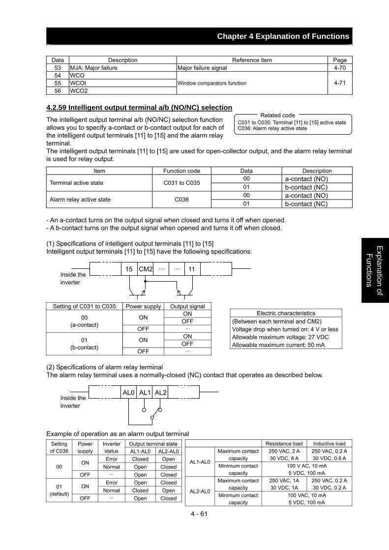
Chapter 4 Explanation of Functions
4 - 61
Explanation of Functions
Data Description Reference item Page53 MJA: Major failure Major failure signal 4-70 54 WCO 55 WCOI 56 WCO2
Window comparators function 4-71
4.2.59 Intelligent output terminal a/b (NO/NC) selection The intelligent output terminal a/b (NO/NC) selection function allows you to specify a-contact or b-contact output for each of the intelligent output terminals [11] to [15] and the alarm relay terminal. The intelligent output terminals [11] to [15] are used for open-collector output, and the alarm relay terminal is used for relay output.
Item Function code Data Description 00 a-contact (NO) Terminal active state C031 to C035 01 b-contact (NC) 00 a-contact (NO) Alarm relay active state C036 01 b-contact (NC)
- An a-contact turns on the output signal when closed and turns it off when opened. - A b-contact turns on the output signal when opened and turns it off when closed. (1) Specifications of intelligent output terminals [11] to [15] Intelligent output terminals [11] to [15] have the following specifications:
15 CM2 … … 11
Setting of C031 to C035 Power supply Output signal ON ON OFF 00
(a-contact) OFF -
ON ON OFF 01
(b-contact) OFF -
(2) Specifications of alarm relay terminal The alarm relay terminal uses a normally-closed (NC) contact that operates as described below.
AL0 AL1 AL2 Example of operation as an alarm output terminal
Output terminal stateSetting of C036
Power supply
Inverter status AL1-AL0 AL2-AL0Error Closed Open
ON Normal Open Closed00
OFF - Open ClosedError Open Closed
ON Normal Closed Open
01 (default)
OFF - Open Closed
C031 to C035: Terminal [11] to [15] active state C036: Alarm relay active state
Related code
Electric characteristics (Between each terminal and CM2) Voltage drop when turned on: 4 V or lessAllowable maximum voltage: 27 VDC Allowable maximum current: 50 mA
Inside the inverter
Inside the inverter
Resistance load Inductive load Maximum contact
capacity 250 VAC, 2 A 30 VDC, 8 A
250 VAC, 0.2 A30 VDC, 0.6 A
AL1-AL0Minimum contact
capacity 100 V AC, 10 mA 5 VDC, 100 mA
Maximum contact capacity
250 VAC, 1A 30 VDC, 1A
250 VAC, 0.2 A30 VDC, 0.2 A
AL2-AL0Minimum contact
capacity 100 VAC, 10 mA 5 VDC, 100 mA
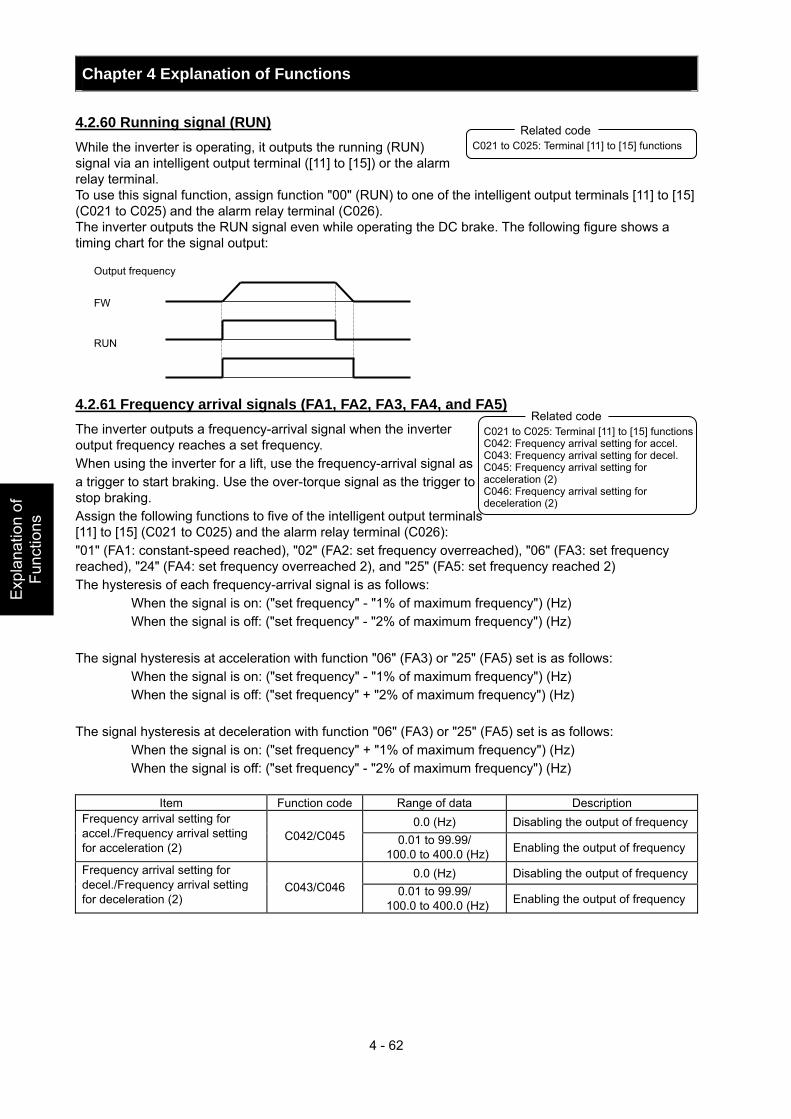
Chapter 4 Explanation of Functions
4 - 62
Exp
lana
tion
of
Func
tions
4.2.60 Running signal (RUN) While the inverter is operating, it outputs the running (RUN) signal via an intelligent output terminal ([11] to [15]) or the alarm relay terminal. To use this signal function, assign function "00" (RUN) to one of the intelligent output terminals [11] to [15] (C021 to C025) and the alarm relay terminal (C026). The inverter outputs the RUN signal even while operating the DC brake. The following figure shows a timing chart for the signal output: 4.2.61 Frequency arrival signals (FA1, FA2, FA3, FA4, and FA5) The inverter outputs a frequency-arrival signal when the inverter output frequency reaches a set frequency. When using the inverter for a lift, use the frequency-arrival signal as a trigger to start braking. Use the over-torque signal as the trigger to stop braking. Assign the following functions to five of the intelligent output terminals [11] to [15] (C021 to C025) and the alarm relay terminal (C026): "01" (FA1: constant-speed reached), "02" (FA2: set frequency overreached), "06" (FA3: set frequency reached), "24" (FA4: set frequency overreached 2), and "25" (FA5: set frequency reached 2) The hysteresis of each frequency-arrival signal is as follows:
When the signal is on: ("set frequency" - "1% of maximum frequency") (Hz) When the signal is off: ("set frequency" - "2% of maximum frequency") (Hz)
The signal hysteresis at acceleration with function "06" (FA3) or "25" (FA5) set is as follows:
When the signal is on: ("set frequency" - "1% of maximum frequency") (Hz) When the signal is off: ("set frequency" + "2% of maximum frequency") (Hz)
The signal hysteresis at deceleration with function "06" (FA3) or "25" (FA5) set is as follows:
When the signal is on: ("set frequency" + "1% of maximum frequency") (Hz) When the signal is off: ("set frequency" - "2% of maximum frequency") (Hz)
Item Function code Range of data Description
0.0 (Hz) Disabling the output of frequencyFrequency arrival setting for accel./Frequency arrival setting for acceleration (2)
C042/C045 0.01 to 99.99/ 100.0 to 400.0 (Hz) Enabling the output of frequency
0.0 (Hz) Disabling the output of frequencyFrequency arrival setting for decel./Frequency arrival setting for deceleration (2)
C043/C046 0.01 to 99.99/ 100.0 to 400.0 (Hz) Enabling the output of frequency
C021 to C025: Terminal [11] to [15] functions Related code
Output frequency
RUN
FW
C021 to C025: Terminal [11] to [15] functionsC042: Frequency arrival setting for accel. C043: Frequency arrival setting for decel. C045: Frequency arrival setting for acceleration (2) C046: Frequency arrival setting for deceleration (2)
Related code

Chapter 4 Explanation of Functions
4 - 63
Explanation of Functions
(1) Signal output when the constant-speed frequency is reached (01: FA1) The inverter outputs the signal when the output frequency reaches the frequency specified by a frequency setting (F001, A020, A220, or A320) or multispeed setting (A021 to A035). (2) Signal output when the set frequency is exceeded (02: FA2 or 24: FA4) The inverter outputs the signal when the output frequency exceeds the acceleration or deceleration frequency specified by a frequency setting ("C042" or "C043" [FA2] or "C045" or "C046" [FA4]). (3) Signal output only when the set frequency is reached (06: FA3 or 25: FA5) The inverter outputs the signal only when the output frequency reaches the frequency specified by a frequency setting ("C042" or "C043" [FA3] or "C045" or "C046" [FA5]).
fofffon
Output frequency
FA1
Set frequency fon: 1% of maximum frequency foff: 2% of maximum frequency
(Example) Maximum frequency (fmax) = 120 Hz Set frequency (fset) = 60 Hz fon = 120 x 0.01 = 1.2 (Hz) foff = 120 x 0.02 = 2.4 (Hz) At acceleration, the signal turns on when the output frequency reaches 58.8 Hz (60 - 1.2 = 58.8). At deceleration, the signal turns off when the output frequency reaches 57.6 Hz (60 - 2.4 = 57.6).
C042/C045 C043/C046
fon fofffon: 1% of maximum frequency foff: 2% of maximum frequency Output frequency
FA2/FA5
fon
fon
fofffoff
C043/C046
C042/C045
Output frequency
FA3/FA5
fon: 1% of maximum frequency foff: 2% of maximum frequency
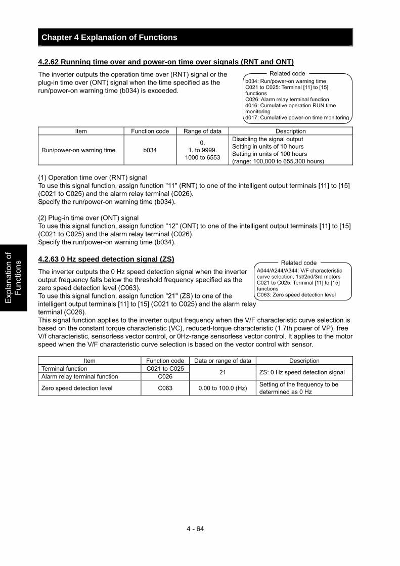
Chapter 4 Explanation of Functions
4 - 64
Exp
lana
tion
of
Func
tions
4.2.62 Running time over and power-on time over signals (RNT and ONT) The inverter outputs the operation time over (RNT) signal or the plug-in time over (ONT) signal when the time specified as the run/power-on warning time (b034) is exceeded.
Item Function code Range of data Description
Run/power-on warning time b034 0.
1. to 9999. 1000 to 6553
Disabling the signal output Setting in units of 10 hours Setting in units of 100 hours (range: 100,000 to 655,300 hours)
(1) Operation time over (RNT) signal To use this signal function, assign function "11" (RNT) to one of the intelligent output terminals [11] to [15] (C021 to C025) and the alarm relay terminal (C026). Specify the run/power-on warning time (b034). (2) Plug-in time over (ONT) signal To use this signal function, assign function "12" (ONT) to one of the intelligent output terminals [11] to [15] (C021 to C025) and the alarm relay terminal (C026). Specify the run/power-on warning time (b034). 4.2.63 0 Hz speed detection signal (ZS) The inverter outputs the 0 Hz speed detection signal when the inverter output frequency falls below the threshold frequency specified as the zero speed detection level (C063). To use this signal function, assign function "21" (ZS) to one of the intelligent output terminals [11] to [15] (C021 to C025) and the alarm relay terminal (C026). This signal function applies to the inverter output frequency when the V/F characteristic curve selection is based on the constant torque characteristic (VC), reduced-torque characteristic (1.7th power of VP), free V/f characteristic, sensorless vector control, or 0Hz-range sensorless vector control. It applies to the motor speed when the V/F characteristic curve selection is based on the vector control with sensor.
Item Function code Data or range of data Description Terminal function C021 to C025Alarm relay terminal function C026
21 ZS: 0 Hz speed detection signal
Zero speed detection level C063 0.00 to 100.0 (Hz) Setting of the frequency to be determined as 0 Hz
b034: Run/power-on warning time C021 to C025: Terminal [11] to [15] functions C026: Alarm relay terminal function d016: Cumulative operation RUN time monitoring d017: Cumulative power-on time monitoring
Related code
A044/A244/A344: V/F characteristic curve selection, 1st/2nd/3rd motors C021 to C025: Terminal [11] to [15] functions C063: Zero speed detection level
Related code
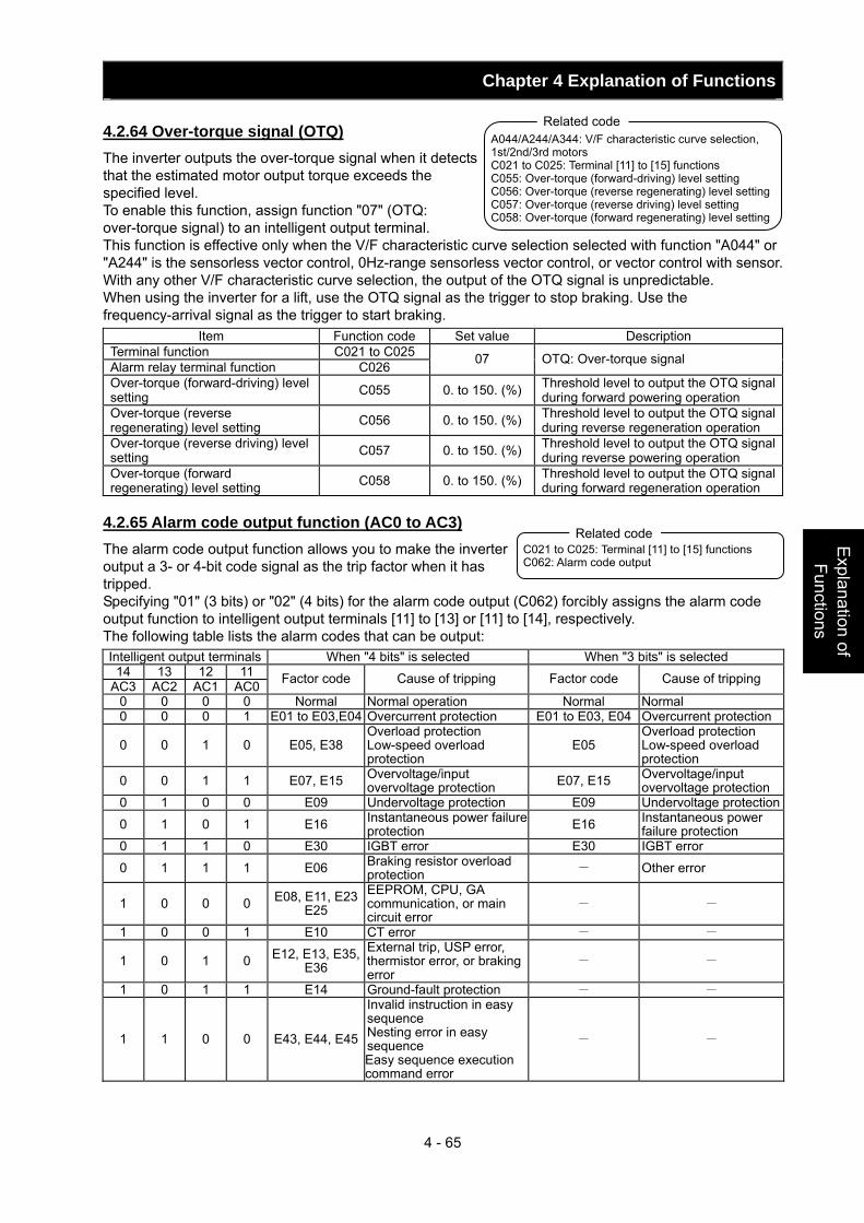
Chapter 4 Explanation of Functions
4 - 65
Explanation of Functions
4.2.64 Over-torque signal (OTQ) The inverter outputs the over-torque signal when it detects that the estimated motor output torque exceeds the specified level. To enable this function, assign function "07" (OTQ: over-torque signal) to an intelligent output terminal. This function is effective only when the V/F characteristic curve selection selected with function "A044" or "A244" is the sensorless vector control, 0Hz-range sensorless vector control, or vector control with sensor. With any other V/F characteristic curve selection, the output of the OTQ signal is unpredictable. When using the inverter for a lift, use the OTQ signal as the trigger to stop braking. Use the frequency-arrival signal as the trigger to start braking.
Item Function code Set value Description Terminal function C021 to C025 Alarm relay terminal function C026 07 OTQ: Over-torque signal
Over-torque (forward-driving) level setting C055 0. to 150. (%) Threshold level to output the OTQ signal
during forward powering operation Over-torque (reverse regenerating) level setting C056 0. to 150. (%) Threshold level to output the OTQ signal
during reverse regeneration operation Over-torque (reverse driving) level setting C057 0. to 150. (%) Threshold level to output the OTQ signal
during reverse powering operation Over-torque (forward regenerating) level setting C058 0. to 150. (%) Threshold level to output the OTQ signal
during forward regeneration operation 4.2.65 Alarm code output function (AC0 to AC3) The alarm code output function allows you to make the inverter output a 3- or 4-bit code signal as the trip factor when it has tripped. Specifying "01" (3 bits) or "02" (4 bits) for the alarm code output (C062) forcibly assigns the alarm code output function to intelligent output terminals [11] to [13] or [11] to [14], respectively. The following table lists the alarm codes that can be output: Intelligent output terminals When "4 bits" is selected When "3 bits" is selected
14 13 12 11 AC3 AC2 AC1 AC0 Factor code Cause of tripping Factor code Cause of tripping
0 0 0 0 Normal Normal operation Normal Normal 0 0 0 1 E01 to E03,E04 Overcurrent protection E01 to E03, E04 Overcurrent protection
0 0 1 0 E05, E38 Overload protection Low-speed overload protection
E05 Overload protection Low-speed overload protection
0 0 1 1 E07, E15 Overvoltage/input overvoltage protection E07, E15 Overvoltage/input
overvoltage protection 0 1 0 0 E09 Undervoltage protection E09 Undervoltage protection
0 1 0 1 E16 Instantaneous power failure protection E16 Instantaneous power
failure protection 0 1 1 0 E30 IGBT error E30 IGBT error
0 1 1 1 E06 Braking resistor overload protection - Other error
1 0 0 0 E08, E11, E23E25
EEPROM, CPU, GA communication, or main circuit error
- -
1 0 0 1 E10 CT error - -
1 0 1 0 E12, E13, E35,E36
External trip, USP error, thermistor error, or braking error
- -
1 0 1 1 E14 Ground-fault protection - -
1 1 0 0 E43, E44, E45
Invalid instruction in easy sequence Nesting error in easy sequence Easy sequence execution command error
- -
A044/A244/A344: V/F characteristic curve selection, 1st/2nd/3rd motors C021 to C025: Terminal [11] to [15] functions C055: Over-torque (forward-driving) level setting C056: Over-torque (reverse regenerating) level setting C057: Over-torque (reverse driving) level setting C058: Over-torque (forward regenerating) level setting
Related code
C021 to C025: Terminal [11] to [15] functions C062: Alarm code output
Related code
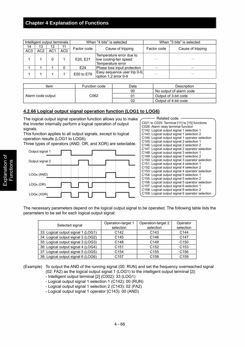
Chapter 4 Explanation of Functions
4 - 66
Exp
lana
tion
of
Func
tions
Intelligent output terminals When "4 bits" is selected When "3 bits" is selected
14 13 12 11 AC3 AC2 AC1 AC0 Factor code Cause of tripping Factor code Cause of tripping
1 1 0 1 E20, E21 Temperature error due to low cooling-fan speed Temperature error
- -
1 1 1 0 E24 Phase loss input protection - -
1 1 1 1 E50 to E79 Easy sequence user trip 0-9, option 1,2 error 0-9 - -
Item Function code Data Description
00 No output of alarm code 01 Output of 3-bit code Alarm code output C062 02 Output of 4-bit code
4.2.66 Logical output signal operation function (LOG1 to LOG6) The logical output signal operation function allows you to make the inverter internally perform a logical operation of output signals. This function applies to all output signals, except to logical operation results (LOG1 to LOG6). Three types of operators (AND, OR, and XOR) are selectable. The necessary parameters depend on the logical output signal to be operated. The following table lists the parameters to be set for each logical output signal:
Selected signal Operation-target 1 selection
Operation-target 2 selection
Operator selection
33: Logical output signal 1 (LOG1) C142 C143 C144 34: Logical output signal 2 (LOG2) C145 C146 C147 35: Logical output signal 3 (LOG3) C148 C149 C150 36: Logical output signal 4 (LOG4) C151 C152 C153 37: Logical output signal 5 (LOG5) C154 C155 C156 38: Logical output signal 6 (LOG6) C157 C158 C159
(Example) To output the AND of the running signal (00: RUN) and set the frequency overreached signal
(02: FA2) as the logical output signal 1 (LOG1) to the intelligent output terminal [2]: - Intelligent output terminal [2] (C002): 33 (LOG1) - Logical output signal 1 selection 1 (C142): 00 (RUN) - Logical output signal 1 selection 2 (C143): 02 (FA2) - Logical output signal 1 operator (C143): 00 (AND)
C021 to C025: Terminal [11] to [15] functions C026: Alarm relay terminal function C142: Logical output signal 1 selection 1 C143: Logical output signal 1 selection 2 C144: Logical output signal 1 operator selection C145: Logical output signal 2 selection 1 C146: Logical output signal 2 selection 2 C147: Logical output signal 2 operator selection C148: Logical output signal 3 selection 1 C149: Logical output signal 3 selection 2 C150: Logical output signal 3 operator selection C151: Logical output signal 4 selection 1 C152: Logical output signal 4 selection 2 C153: Logical output signal 4 operator selection C154: Logical output signal 5 selection 1 C155: Logical output signal 5 selection 2 C156: Logical output signal 5 operator selection C157: Logical output signal 6 selection 1 C158: Logical output signal 6 selection 2 C159: Logical output signal 6 operator selection
Related code
LOGx (AND)
LOGx (OR)
LOGx (XOR)
Output signal 1
Output signal 2
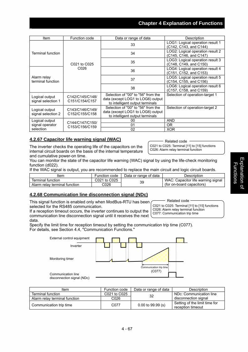
Chapter 4 Explanation of Functions
4 - 67
Explanation of Functions
Item Function code Data or range of data Description
33 LOG1: Logical operation result 1(C142, C143, and C144)
34 LOG2: Logical operation result 2(C145, C146, and C147) Terminal function
35 LOG3: Logical operation result 3(C148, C149, and C150)
36 LOG4: Logical operation result 4(C151, C152, and C153)
37 LOG5: Logical operation result 5(C154, C155, and C156)
Alarm relay terminal function
C021 to C025 C026
38 LOG6: Logical operation result 6(C157, C158, and C159)
Logical output signal selection 1
C142/C145/C148/ C151/C154/C157
Selection of "00" to "56" from the data (except LOG1 to LOG6) output
to intelligent output terminals
Selection of operation-target 1
Logical output signal selection 2
C143/C146/C149/ C152/C155/C158
Selection of "00" to "56" from the data (except LOG1 to LOG6) output
to intelligent output terminals
Selection of operation-target 2
00 AND 01 OR
Logical output signal operator selection
C144/C147/C150/ C153/C156/C159
02 XOR 4.2.67 Capacitor life warning signal (WAC) The inverter checks the operating life of the capacitors on the internal circuit boards on the basis of the internal temperature and cumulative power-on time. You can monitor the state of the capacitor life warning (WAC) signal by using the life-check monitoring function (d022). If the WAC signal is output, you are recommended to replace the main circuit and logic circuit boards.
Item Function code Data or range of data Description Terminal function C021 to C025Alarm relay terminal function C026 39 WAC: Capacitor life warning signal
(for on-board capacitors) 4.2.68 Communication line disconnection signal (NDc) This signal function is enabled only when ModBus-RTU has been selected for the RS485 communication. If a reception timeout occurs, the inverter continues to output the communication line disconnection signal until it receives the next data. Specify the limit time for reception timeout by setting the communication trip time (C077). For details, see Section 4.4, "Communication Functions."
Item Function code Data or range of data Description Terminal function C021 to C025Alarm relay terminal function C026 32 NDc: Communication line
disconnection signal
Communication trip time C077 0.00 to 99.99 (s) Setting of the limit time for reception timeout
C021 to C025: Terminal [11] to [15] functions C026: Alarm relay terminal function
Related code
C021 to C025: Terminal [11] to [15] functions C026: Alarm relay terminal function C077: Communication trip time
Related code
(C077)
External control equipment
Inverter
Monitoring timer
Communication line disconnection signal (NDc)
Communication trip time
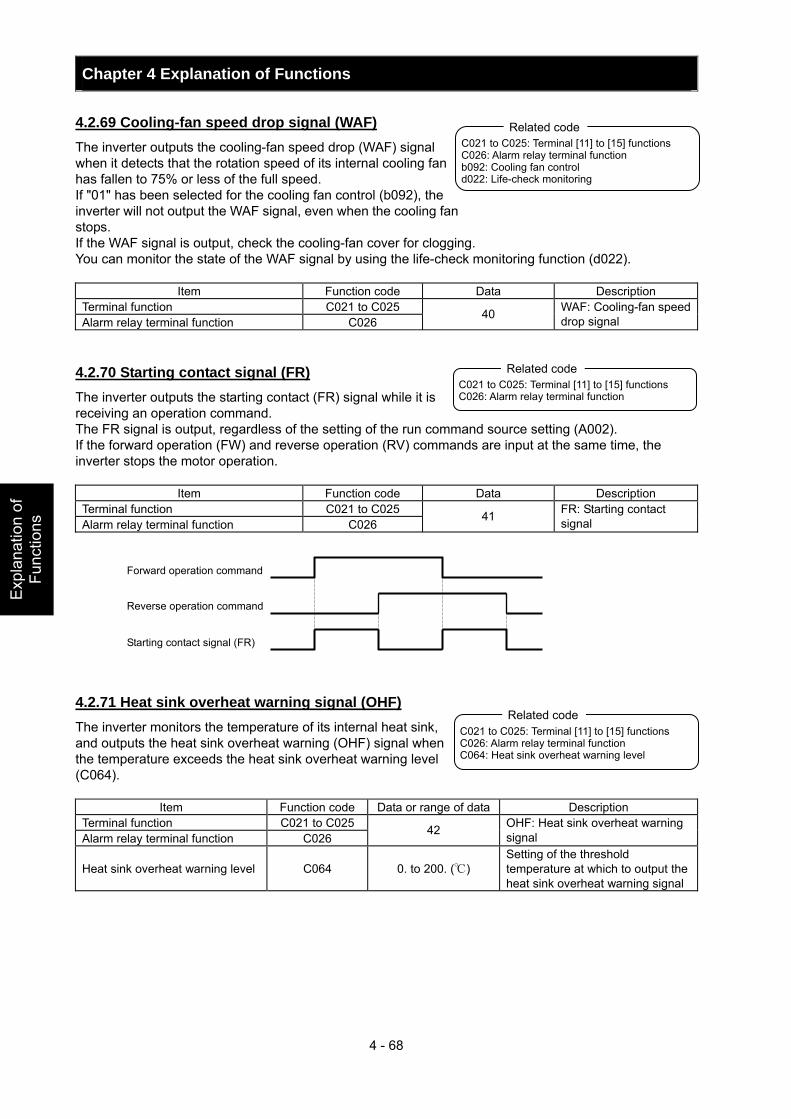
Chapter 4 Explanation of Functions
4 - 68
Exp
lana
tion
of
Func
tions
4.2.69 Cooling-fan speed drop signal (WAF) The inverter outputs the cooling-fan speed drop (WAF) signal when it detects that the rotation speed of its internal cooling fan has fallen to 75% or less of the full speed. If "01" has been selected for the cooling fan control (b092), the inverter will not output the WAF signal, even when the cooling fan stops. If the WAF signal is output, check the cooling-fan cover for clogging. You can monitor the state of the WAF signal by using the life-check monitoring function (d022).
Item Function code Data Description Terminal function C021 to C025 Alarm relay terminal function C026
40 WAF: Cooling-fan speed drop signal
4.2.70 Starting contact signal (FR) The inverter outputs the starting contact (FR) signal while it is receiving an operation command. The FR signal is output, regardless of the setting of the run command source setting (A002). If the forward operation (FW) and reverse operation (RV) commands are input at the same time, the inverter stops the motor operation.
Item Function code Data Description Terminal function C021 to C025 Alarm relay terminal function C026
41 FR: Starting contact signal
4.2.71 Heat sink overheat warning signal (OHF) The inverter monitors the temperature of its internal heat sink, and outputs the heat sink overheat warning (OHF) signal when the temperature exceeds the heat sink overheat warning level (C064).
Item Function code Data or range of data Description Terminal function C021 to C025 Alarm relay terminal function C026
42 OHF: Heat sink overheat warning signal
Heat sink overheat warning level C064 0. to 200. () Setting of the threshold temperature at which to output the heat sink overheat warning signal
C021 to C025: Terminal [11] to [15] functions C026: Alarm relay terminal function b092: Cooling fan control d022: Life-check monitoring
Related code
C021 to C025: Terminal [11] to [15] functions C026: Alarm relay terminal function
Related code
Forward operation command
Reverse operation command
Starting contact signal (FR)
C021 to C025: Terminal [11] to [15] functions C026: Alarm relay terminal function C064: Heat sink overheat warning level
Related code
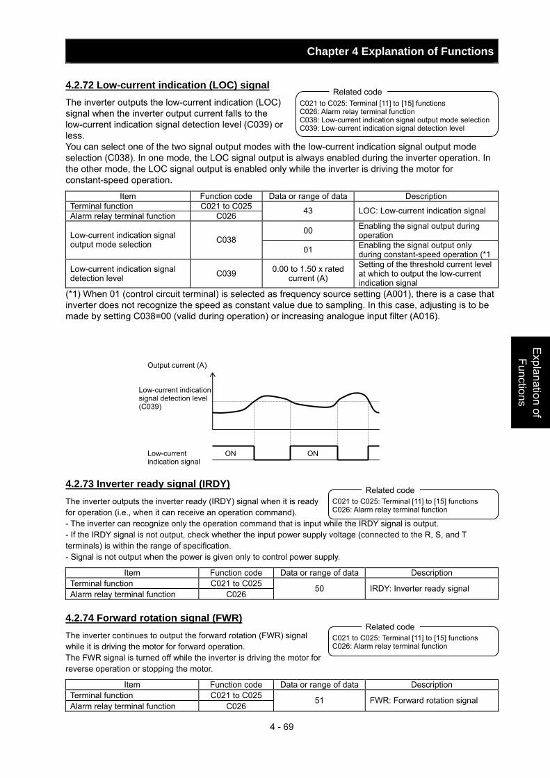
Chapter 4 Explanation of Functions
4 - 69
Explanation of Functions
4.2.72 Low-current indication (LOC) signal The inverter outputs the low-current indication (LOC) signal when the inverter output current falls to the low-current indication signal detection level (C039) or less. You can select one of the two signal output modes with the low-current indication signal output mode selection (C038). In one mode, the LOC signal output is always enabled during the inverter operation. In the other mode, the LOC signal output is enabled only while the inverter is driving the motor for constant-speed operation.
Item Function code Data or range of data Description Terminal function C021 to C025 Alarm relay terminal function C026 43 LOC: Low-current indication signal
00 Enabling the signal output during operation Low-current indication signal
output mode selection C038 01 Enabling the signal output only
during constant-speed operation (*1
Low-current indication signal detection level C039 0.00 to 1.50 x rated
current (A)
Setting of the threshold current level at which to output the low-current indication signal
(*1) When 01 (control circuit terminal) is selected as frequency source setting (A001), there is a case that inverter does not recognize the speed as constant value due to sampling. In this case, adjusting is to be made by setting C038=00 (valid during operation) or increasing analogue input filter (A016). 4.2.73 Inverter ready signal (IRDY) The inverter outputs the inverter ready (IRDY) signal when it is ready for operation (i.e., when it can receive an operation command). - The inverter can recognize only the operation command that is input while the IRDY signal is output. - If the IRDY signal is not output, check whether the input power supply voltage (connected to the R, S, and T terminals) is within the range of specification. - Signal is not output when the power is given only to control power supply.
Item Function code Data or range of data Description Terminal function C021 to C025 Alarm relay terminal function C026
50 IRDY: Inverter ready signal
4.2.74 Forward rotation signal (FWR) The inverter continues to output the forward rotation (FWR) signal while it is driving the motor for forward operation. The FWR signal is turned off while the inverter is driving the motor for reverse operation or stopping the motor.
Item Function code Data or range of data Description Terminal function C021 to C025 Alarm relay terminal function C026
51 FWR: Forward rotation signal
C021 to C025: Terminal [11] to [15] functions C026: Alarm relay terminal function C038: Low-current indication signal output mode selection C039: Low-current indication signal detection level
Related code
C021 to C025: Terminal [11] to [15] functions C026: Alarm relay terminal function
Related code
C021 to C025: Terminal [11] to [15] functions C026: Alarm relay terminal function
Related code
Output current (A)
Low-current indication signal detection level (C039)
Low-current indication signal
ONON
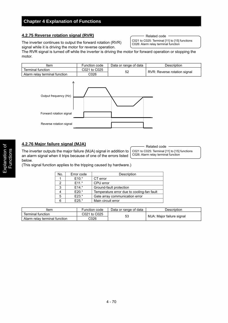
Chapter 4 Explanation of Functions
4 - 70
Exp
lana
tion
of
Func
tions
4.2.75 Reverse rotation signal (RVR) The inverter continues to output the forward rotation (RVR) signal while it is driving the motor for reverse operation. The RVR signal is turned off while the inverter is driving the motor for forward operation or stopping the motor.
Item Function code Data or range of data Description Terminal function C021 to C025 Alarm relay terminal function C026
52 RVR: Reverse rotation signal
4.2.76 Major failure signal (MJA) The inverter outputs the major failure (MJA) signal in addition to an alarm signal when it trips because of one of the errors listed below. (This signal function applies to the tripping caused by hardware.)
No. Error code Description 1 E10.* CT error 2 E11.* CPU error 3 E14.* Ground-fault protection 4 E20.* Temperature error due to cooling-fan fault 5 E23.* Gate array communication error 6 E25.* Main circuit error
Item Function code Data or range of data Description
Terminal function C021 to C025 Alarm relay terminal function C026
53 MJA: Major failure signal
C021 to C025: Terminal [11] to [15] functions C026: Alarm relay terminal function
Related code
Output frequency (Hz)
Forward rotation signal
Reverse rotation signal
C021 to C025: Terminal [11] to [15] functions C026: Alarm relay terminal function
Related code
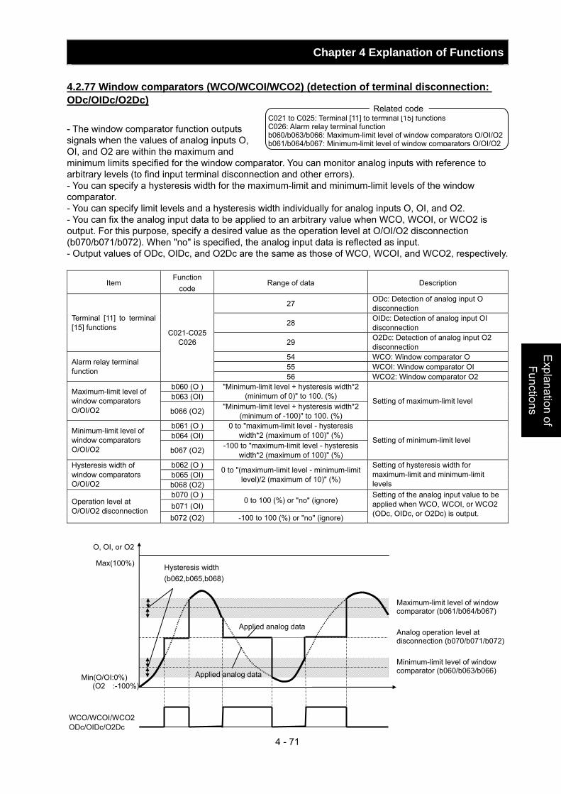
Chapter 4 Explanation of Functions
4 - 71
Explanation of Functions
4.2.77 Window comparators (WCO/WCOI/WCO2) (detection of terminal disconnection: ODc/OIDc/O2Dc) - The window comparator function outputs signals when the values of analog inputs O, OI, and O2 are within the maximum and minimum limits specified for the window comparator. You can monitor analog inputs with reference to arbitrary levels (to find input terminal disconnection and other errors). - You can specify a hysteresis width for the maximum-limit and minimum-limit levels of the window comparator. - You can specify limit levels and a hysteresis width individually for analog inputs O, OI, and O2. - You can fix the analog input data to be applied to an arbitrary value when WCO, WCOI, or WCO2 is output. For this purpose, specify a desired value as the operation level at O/OI/O2 disconnection (b070/b071/b072). When "no" is specified, the analog input data is reflected as input. - Output values of ODc, OIDc, and O2Dc are the same as those of WCO, WCOI, and WCO2, respectively.
Item Function
code Range of data Description
27 ODc: Detection of analog input O disconnection
28 OIDc: Detection of analog input OI disconnection
Terminal [11] to terminal [15] functions
29 O2Dc: Detection of analog input O2 disconnection
54 WCO: Window comparator O 55 WCOI: Window comparator OI Alarm relay terminal
function
C021-C025 C026
56 WCO2: Window comparator O2 b060 (O ) b063 (OI)
"Minimum-limit level + hysteresis width*2 (minimum of 0)" to 100. (%) Maximum-limit level of
window comparators O/OI/O2 b066 (O2) "Minimum-limit level + hysteresis width*2
(minimum of -100)" to 100. (%)
Setting of maximum-limit level
b061 (O ) b064 (OI)
0 to "maximum-limit level - hysteresis width*2 (maximum of 100)" (%) Minimum-limit level of
window comparators O/OI/O2 b067 (O2) -100 to "maximum-limit level - hysteresis
width*2 (maximum of 100)" (%)
Setting of minimum-limit level
b062 (O ) b065 (OI)
Hysteresis width of window comparators O/OI/O2 b068 (O2)
0 to "(maximum-limit level - minimum-limit level)/2 (maximum of 10)" (%)
Setting of hysteresis width for maximum-limit and minimum-limit levels
b070 (O ) b071 (OI)
0 to 100 (%) or "no" (ignore) Operation level at O/OI/O2 disconnection
b072 (O2) -100 to 100 (%) or "no" (ignore)
Setting of the analog input value to be applied when WCO, WCOI, or WCO2 (ODc, OIDc, or O2Dc) is output.
C021 to C025: Terminal [11] to terminal [15] functions C026: Alarm relay terminal function b060/b063/b066: Maximum-limit level of window comparators O/OI/O2 b061/b064/b067: Minimum-limit level of window comparators O/OI/O2
Related code
Maximum-limit level of window comparator (b061/b064/b067)
Minimum-limit level of window comparator (b060/b063/b066)
WCO/WCOI/WCO2 ODc/OIDc/O2Dc
Max(100%)
Min(O/OI:0%) (O2 :-100%)
O, OI, or O2
Applied analog data
Applied analog data
Analog operation level at disconnection (b070/b071/b072)
Hysteresis width (b062,b065,b068)
Chapter 4 Explanation of Functions
4 - 72
Exp
lana
tion
of
Func
tions
4.2.78 Output signal delay/hold function The output signal delay/hold function allows you to set on-delay and off-delay times for each output terminal. Since every output signal is turned on or off immediately when the relevant condition is satisfied, signal chattering may occur if signal outputs conflict with each other. Use this function to avoid such a problem by holding or delaying specific signal outputs. To use this function, set on-delay and off-delay times for individual output terminals (a total of six terminals, such as intelligent output terminals [11] to [15] and the alarm relay terminal).
Output terminal On-delay time Off-delay time 11 C130 C131 12 C132 C133 13 C134 C135 14 C136 C137 15 C138 C139
RY(AL*) C140 C141
Item Function code Range of data Description
Output on C130/C132/C134/ C136/C138/C140 0.0 to 100.0 (s) Setting of on
Output off C131/C133/C135/ C137/C139/C141 0.0 to 100.0 (s) Setting of off
4.2.79 Input terminal response time - The input terminal response time function allows you to specify a sampling time for each of intelligent input terminals 1 to 8 and the FW terminal. You can use this function effectively to remove noise (e.g., chattering). - If chattering hinders constant input from an input terminal, increase the response time setting for the input terminal. Note that an increase in response time deteriorates the response. The response time can be set in a range of about 2 to 400 ms (corresponding to settings of 0 to 200).
Item Function code Range of data Description Response time of intelligent input terminals 1 to 8 C160-C167
FW terminal response time C168 0. to 200. Variable in step of 1
4.2.80 External thermistor function (TH) The external thermistor function allows you to connect an external thermistor installed in external equipment (e.g., motor) to the inverter, and use the thermistor for the thermal protection of the external equipment. Connect the external thermistor to control circuit terminals TH and CM1. Make the functional settings according to the thermistor specifications as described below. When using this function, the wiring distance between the inverter and motor must be 20 m or less. Since the thermistor current is weak, isolate the thermistor wiring to the inverter from other wirings appropriately to prevent the thermistor signal from being affected by the noise caused by other signal currents, including the motor current.
Item Function code Range of data Description 00 Disabling the external thermistor (TH) function
01 Enabling the TH function (resistor element with a positive temperature coefficient [PTC]) Thermistor for thermal
protection control b098
02 Enabling the TH function (resistor element with a negative temperature coefficient [NTC])
Thermal protection level setting b099 0 to 9999. (Ω)
Setting of the thermal resistance level (according to the thermistor specifications) at which to trigger tripping
Thermistor input tuning C085 0.0 to 999.9/1000. Setting for gain adjustment Note: Specifying "01" for the thermistor for thermal protection control (b098) without an external thermistor
connected makes the inverter trip.
C130: Output 11 on-delay time C131: Output 11 off-delay time C132: Output 12 on-delay time C133: Output 12 off-delay time C134: Output 13 on-delay time C135: Output 13 off-delay time C136: Output 14 on-delay time C137: Output 14 off-delay time C138: Output 15 on-delay time C139: Output 15 off-delay time C140: Output RY on-delay time C141: Output RY off-delay time
Related code
b098: Thermistor for thermal protection control b099: Thermal protection level setting C085: Thermistor input tuning
Related code
C160 to C167: Response time of intelligent input terminals 1 to 8 C168: FW terminal response time
Related code
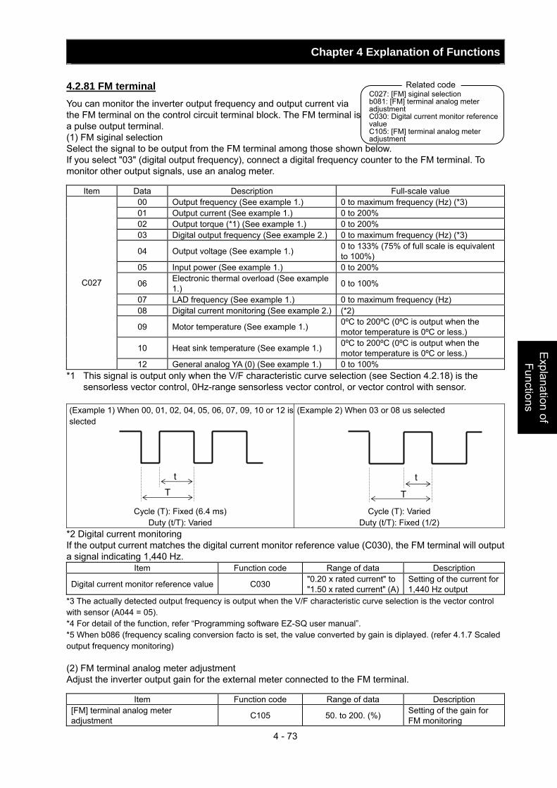
Chapter 4 Explanation of Functions
4 - 73
Explanation of Functions
4.2.81 FM terminal You can monitor the inverter output frequency and output current via the FM terminal on the control circuit terminal block. The FM terminal is a pulse output terminal. (1) FM siginal selection Select the signal to be output from the FM terminal among those shown below. If you select "03" (digital output frequency), connect a digital frequency counter to the FM terminal. To monitor other output signals, use an analog meter.
Item Data Description Full-scale value 00 Output frequency (See example 1.) 0 to maximum frequency (Hz) (*3) 01 Output current (See example 1.) 0 to 200% 02 Output torque (*1) (See example 1.) 0 to 200% 03 Digital output frequency (See example 2.) 0 to maximum frequency (Hz) (*3)
04 Output voltage (See example 1.) 0 to 133% (75% of full scale is equivalent to 100%)
05 Input power (See example 1.) 0 to 200%
06 Electronic thermal overload (See example 1.) 0 to 100%
07 LAD frequency (See example 1.) 0 to maximum frequency (Hz) 08 Digital current monitoring (See example 2.) (*2)
09 Motor temperature (See example 1.) 0ºC to 200ºC (0ºC is output when the motor temperature is 0ºC or less.)
10 Heat sink temperature (See example 1.) 0ºC to 200ºC (0ºC is output when the motor temperature is 0ºC or less.)
C027
12 General analog YA (0) (See example 1.) 0 to 100% *1 This signal is output only when the V/F characteristic curve selection (see Section 4.2.18) is the
sensorless vector control, 0Hz-range sensorless vector control, or vector control with sensor. (Example 1) When 00, 01, 02, 04, 05, 06, 07, 09, 10 or 12 is slected
Cycle (T): Fixed (6.4 ms) Duty (t/T): Varied
(Example 2) When 03 or 08 us selected
Cycle (T): Varied Duty (t/T): Fixed (1/2)
*2 Digital current monitoring If the output current matches the digital current monitor reference value (C030), the FM terminal will output a signal indicating 1,440 Hz.
Item Function code Range of data Description
Digital current monitor reference value C030 "0.20 x rated current" to "1.50 x rated current" (A)
Setting of the current for 1,440 Hz output
*3 The actually detected output frequency is output when the V/F characteristic curve selection is the vector control with sensor (A044 = 05). *4 For detail of the function, refer “Programming software EZ-SQ user manual”. *5 When b086 (frequency scaling conversion facto is set, the value converted by gain is diplayed. (refer 4.1.7 Scaled output frequency monitoring) (2) FM terminal analog meter adjustment Adjust the inverter output gain for the external meter connected to the FM terminal.
Item Function code Range of data Description [FM] terminal analog meter adjustment C105 50. to 200. (%) Setting of the gain for
FM monitoring
t
Tt
T
C027: [FM] siginal selectionb081: [FM] terminal analog meter adjustment C030: Digital current monitor reference value C105: [FM] terminal analog meter adjustment
Related code
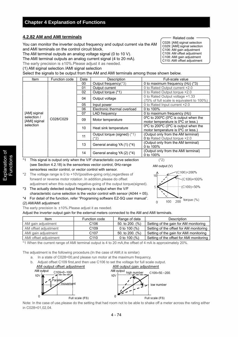
Chapter 4 Explanation of Functions
4 - 74
Exp
lana
tion
of
Func
tions
4.2.82 AM and AMI terminals You can monitor the inverter output frequency and output current via the AM and AMI terminals on the control circuit block. The AM terminal outputs an analog voltage signal (0 to 10 V). The AMI terminal outputs an analog current signal (4 to 20 mA). The early precision is ±10%.Please adjust it as needed. (1) AM siginal selection /AMI signal selection Select the signals to be output from the AM and AMI terminals among those shown below.
Item Function code Data Description Full-scale value 00 Output frequency(*3) 0 to maximum frequency (Hz) (*3) 01 Output current 0 to Rated Output current ×2.0 02 Output torque (*1) 0 to Rated Output torque ×2.0
04 Output voltage 0 to Rated Output voltage ×1.33 (75% of full scale is equivalent to 100%)
05 Input power 0 to Rated Input current ×2.0 06 Electronic thermal overload 0 to 100% 07 LAD frequency 0 to maximum frequency (Hz)
09 Motor temperature 0ºC to 200ºC (0ºC is output when the motor temperature is 0ºC or less.)
10 Heat sink temperature 0ºC to 200ºC (0ºC is output when the motor temperature is 0ºC or less.)
11 Output torque (signed) (*1) (*2)
(Output only from the AM terminal) 0 to Rated Output torque ×2.0
13 General analog YA (1) (*4) (Output only from the AM terminal) 0 to 100%
[AM] siginal selection / [AMI] siginal selection
C028/C029
14 General analog YA (2) (*4) (Output only from the AMI terminal) 0 to 100%
*1 This signal is output only when the V/F characteristic curve selection (*2) (see Section 4.2.18) is the sensorless vector control, 0Hz-range sensorless vector control, or vector control with sensor.
*2 The voltage range is 0 to +10V(positive-going only),regardless of forward or reverse motor rotation .In addition,please do offset adjustment when this outputs negative-going of the output torque(signed).
*3 The actually detected output frequency is output when the V/F characteristic curve selection is the vector control with sensor (A044 = 05).
*4 For detail of the function, refer “Programing software EZ-SQ user manual”. (2) AM/AMI adjustment The early precision is ±10%.Please adjust it as needed. Adjust the inverter output gain for the external meters connected to the AM and AMI terminals.
Item Function code Range of data Description AM gain adjustment C106 50. to 200. (%) Setting of the gain for AM monitoring AM offset adjustment C109 0 to 100 (%) Setting of the offset for AM monitoringAMI gain adjustment C107 50. to 200. (%) Setting of the gain for AMI monitoringAMI offset adjustment C110 0 to 100 (%) Setting of the offset for AMI monitoring
*1 When the current range of AMI terminal output is 4 to 20 mA,the offset of 4 mA is approximately 20%. The adjustment is the following procedure.(In the case of AMI,it is similar)
a. In a state of C028=00,and please run motor at the maximum frequency. b. Adjust offset C109 first,and then use C106 to set the voltage for full scale output.
Note: In the case of use,please do the setting that had room not to be able to shake off a meter across the rating either in C028=01,02,04.
C028: [AM] siginal selection C029: [AMI] siginal selection C106: AM gain adjustment C109: AM offset adjustment C108: AMI gain adjustment C110: AMI offset adjustment
Related code
AM output (V)
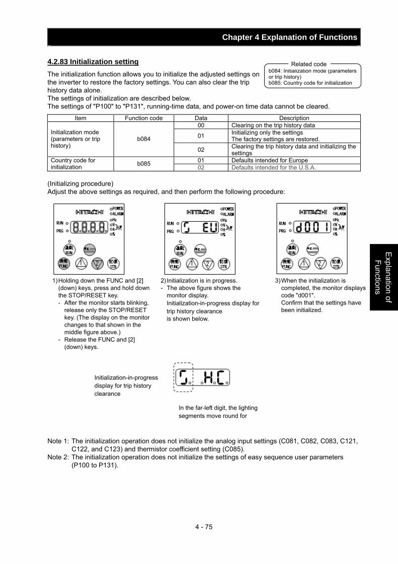
Chapter 4 Explanation of Functions
4 - 75
Explanation of Functions
4.2.83 Initialization setting The initialization function allows you to initialize the adjusted settings on the inverter to restore the factory settings. You can also clear the trip history data alone. The settings of initialization are described below. The settings of "P100" to "P131", running-time data, and power-on time data cannot be cleared.
Item Function code Data Description 00 Clearing on the trip history data
01 Initializing only the settings The factory settings are restored.
Initialization mode (parameters or trip history)
b084
02 Clearing the trip history data and initializing the settings
01 Defaults intended for Europe Country code for initialization b085 02 Defaults intended for the U.S.A.
(Initializing procedure) Adjust the above settings as required, and then perform the following procedure: Note 1: The initialization operation does not initialize the analog input settings (C081, C082, C083, C121,
C122, and C123) and thermistor coefficient setting (C085). Note 2: The initialization operation does not initialize the settings of easy sequence user parameters
(P100 to P131).
b084: Initialization mode (parameters or trip history) b085: Country code for initialization
Related code
Initialization-in-progress display for trip history clearance
In the far-left digit, the lighting segments move round for
1) Holding down the FUNC and [2] (down) keys, press and hold down the STOP/RESET key. - After the monitor starts blinking,
release only the STOP/RESET key. (The display on the monitor changes to that shown in the middle figure above.)
- Release the FUNC and [2] (down) keys.
2) Initialization is in progress. - The above figure shows the
monitor display. Initialization-in-progress display for trip history clearance is shown below.
3) When the initialization is completed, the monitor displays code "d001".
Confirm that the settings have been initialized.
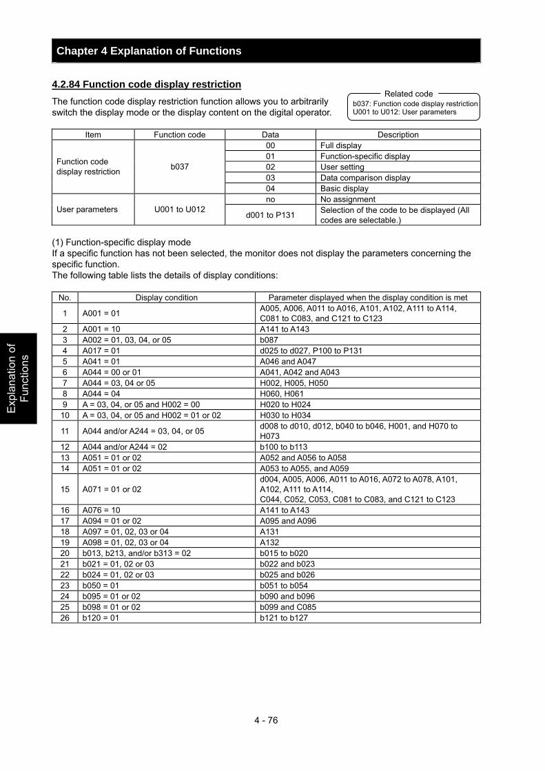
Chapter 4 Explanation of Functions
4 - 76
Exp
lana
tion
of
Func
tions
4.2.84 Function code display restriction The function code display restriction function allows you to arbitrarily switch the display mode or the display content on the digital operator.
Item Function code Data Description 00 Full display 01 Function-specific display 02 User setting 03 Data comparison display
Function code display restriction b037
04 Basic display no No assignment
User parameters U001 to U012 d001 to P131 Selection of the code to be displayed (All
codes are selectable.) (1) Function-specific display mode If a specific function has not been selected, the monitor does not display the parameters concerning the specific function. The following table lists the details of display conditions:
No. Display condition Parameter displayed when the display condition is met
1 A001 = 01 A005, A006, A011 to A016, A101, A102, A111 to A114, C081 to C083, and C121 to C123
2 A001 = 10 A141 to A143 3 A002 = 01, 03, 04, or 05 b087 4 A017 = 01 d025 to d027, P100 to P131 5 A041 = 01 A046 and A047 6 A044 = 00 or 01 A041, A042 and A043 7 A044 = 03, 04 or 05 H002, H005, H050 8 A044 = 04 H060, H061 9 A = 03, 04, or 05 and H002 = 00 H020 to H024
10 A = 03, 04, or 05 and H002 = 01 or 02 H030 to H034
11 A044 and/or A244 = 03, 04, or 05 d008 to d010, d012, b040 to b046, H001, and H070 to H073
12 A044 and/or A244 = 02 b100 to b113 13 A051 = 01 or 02 A052 and A056 to A058 14 A051 = 01 or 02 A053 to A055, and A059
15 A071 = 01 or 02 d004, A005, A006, A011 to A016, A072 to A078, A101, A102, A111 to A114, C044, C052, C053, C081 to C083, and C121 to C123
16 A076 = 10 A141 to A143 17 A094 = 01 or 02 A095 and A096 18 A097 = 01, 02, 03 or 04 A131 19 A098 = 01, 02, 03 or 04 A132 20 b013, b213, and/or b313 = 02 b015 to b020 21 b021 = 01, 02 or 03 b022 and b023 22 b024 = 01, 02 or 03 b025 and b026 23 b050 = 01 b051 to b054 24 b095 = 01 or 02 b090 and b096 25 b098 = 01 or 02 b099 and C085 26 b120 = 01 b121 to b127
b037: Function code display restriction U001 to U012: User parameters
Related code
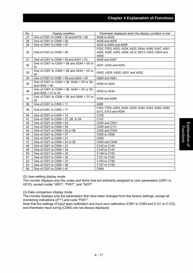
Chapter 4 Explanation of Functions
4 - 77
Explanation of Functions
No. Display condition Parameter displayed when the display condition is met 27 One of C001 to C008 = 05 and A019 = 00 A028 to A035 28 One of C001 to C008 = 06 A038 and A039 29 One of C001 to C008 = 07 A053 to A055 and A059
30 One of C001 to C008 = 08 F202, F203, A203, A204, A220, A244, A246, A247, A261, A262, A292, A293, A294, b212, B213, H203, H204 and H206
31 One of C001 to C008 = 08 and A041 = 01 A246 and A247
32 One of C001 to C008 = 08 and A244 = 00 or 01 A241, A242 and A243
33 One of C001 to C008 = 08 and A244 = 03 or 04 H202, H205, H250, H251 and H252
34 One of C001 to C008 = 08 and A244 = 04 H260 and H261
35 One of C001 to C008 = 08, A244 = 03 or 04, and H202 = 00 H220 to H224
36 One of C001 to C008 = 08, A244 = 03 or 04, and H202 = 01 or 02 H230 to H234
37 One of C001 to C008 = 08 and A094 = 01 or 02 A295 and A296
38 One of C001 to C008 = 11 b088
39 One of C001 to C008 = 17 F302, F303, A303, A304, A320, A342, A343, A392, A393, b312, b313 and H306
40 One of C001 to C008 = 18 C102 41 One of C001 to C008 = 27, 28, or 29 C101 42 One of C021 to C008 = 03 C040 and C041 43 One of C021 to C008 = 26 C040 and C111 44 One of C021 to C008 = 02 or 06 C042 and C043 45 One of C021 to C008 = 07 C055 to C058 46 One of C021 to C008 = 21 C063 47 One of C021 to C008 = 24 or 25 C045 and C046 48 One of C021 to C008 = 33 C142 to C144 49 One of C021 to C008 = 34 C145 to C147 50 One of C021 to C008 = 35 C148 to C150 51 One of C021 to C008 = 36 C151 to C153 52 One of C021 to C008 = 37 C154 to C156 53 One of C021 to C008 = 38 C157 to C159 54 One of C021 to C008 = 42 C064
(2) User-setting display mode The monitor displays only the codes and items that are arbitrarily assigned to user parameters (U001 to U012), except codes "d001", "F001", and "b037". (3) Data comparison display mode The monitor displays only the parameters that have been changed from the factory settings, except all monitoring indications (d***) and code "F001". Note that the settings of input span calibration and input zero calibration (C081 to C083 and C121 to C123), and thermistor input tuning (C085) are not always displayed.
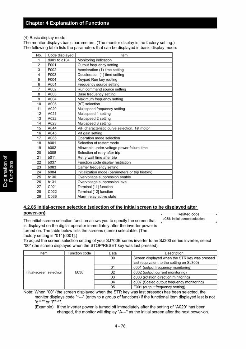
Chapter 4 Explanation of Functions
4 - 78
Exp
lana
tion
of
Func
tions
(4) Basic display mode The monitor displays basic parameters. (The monitor display is the factory setting.) The following table lists the parameters that can be displayed in basic display mode:
No. Code displayed Item 1 d001 to d104 Monitoring indication 2 F001 Output frequency setting 3 F002 Acceleration (1) time setting 4 F003 Deceleration (1) time setting 5 F004 Keypad Run key routing 6 A001 Frequency source setting 7 A002 Run command source setting 8 A003 Base frequency setting 9 A004 Maximum frequency setting
10 A005 [AT] selection 11 A020 Multispeed frequency setting 12 A021 Multispeed 1 setting 13 A022 Multispeed 2 setting 14 A023 Multispeed 3 setting 15 A044 V/F characteristic curve selection, 1st motor 16 A045 V/f gain setting 17 A085 Operation mode selection 18 b001 Selection of restart mode 19 b002 Allowable under-voltage power failure time 20 b008 Selection of retry after trip 21 b011 Retry wait time after trip 22 b037 Function code display restriction 23 b083 Carrier frequency setting 24 b084 Initialization mode (parameters or trip history) 25 b130 Overvoltage suppression enable 26 b131 Overvoltage suppression level 27 C021 Terminal [11] function 28 C022 Terminal [12] function 29 C036 Alarm relay active state
4.2.85 Initial-screen selection (selection of the initial screen to be displayed after power-on) The initial-screen selection function allows you to specify the screen that is displayed on the digital operator immediately after the inverter power is turned on. The table below lists the screens (items) selectable. (The factory setting is "01" [d001].) To adjust the screen selection setting of your SJ700B series inverter to an SJ300 series inverter, select "00" (the screen displayed when the STOP/RESET key was last pressed).
Item Function code Data Description 00 Screen displayed when the STR key was pressed
last (equivalent to the setting on SJ300) 01 d001 (output frequency monitoring) 02 d002 (output current monitoring) 03 d003 (rotation direction minitoring) 04 d007 (Scaled output frequency monitoring)
Initial-screen selection b038
05 F001 (output frequency setting) Note: When "00" (the screen displayed when the STR key was last pressed) has been selected, the
monitor displays code "*---" (entry to a group of functions) if the functional item displayed last is not "d***" or "F***". (Example) If the inverter power is turned off immediately after the setting of "A020" has been
changed, the monitor will display "A---" as the initial screen after the next power-on.
b038: Initial-screen selection Related code
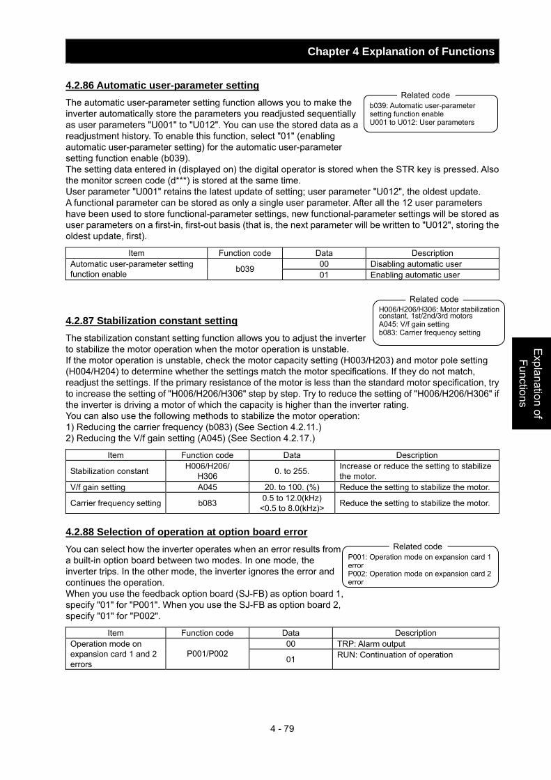
Chapter 4 Explanation of Functions
4 - 79
Explanation of Functions
4.2.86 Automatic user-parameter setting The automatic user-parameter setting function allows you to make the inverter automatically store the parameters you readjusted sequentially as user parameters "U001" to "U012". You can use the stored data as a readjustment history. To enable this function, select "01" (enabling automatic user-parameter setting) for the automatic user-parameter setting function enable (b039). The setting data entered in (displayed on) the digital operator is stored when the STR key is pressed. Also the monitor screen code (d***) is stored at the same time. User parameter "U001" retains the latest update of setting; user parameter "U012", the oldest update. A functional parameter can be stored as only a single user parameter. After all the 12 user parameters have been used to store functional-parameter settings, new functional-parameter settings will be stored as user parameters on a first-in, first-out basis (that is, the next parameter will be written to "U012", storing the oldest update, first).
Item Function code Data Description 00 Disabling automatic user Automatic user-parameter setting
function enable b039 01 Enabling automatic user
4.2.87 Stabilization constant setting The stabilization constant setting function allows you to adjust the inverter to stabilize the motor operation when the motor operation is unstable. If the motor operation is unstable, check the motor capacity setting (H003/H203) and motor pole setting (H004/H204) to determine whether the settings match the motor specifications. If they do not match, readjust the settings. If the primary resistance of the motor is less than the standard motor specification, try to increase the setting of "H006/H206/H306" step by step. Try to reduce the setting of "H006/H206/H306" if the inverter is driving a motor of which the capacity is higher than the inverter rating. You can also use the following methods to stabilize the motor operation: 1) Reducing the carrier frequency (b083) (See Section 4.2.11.) 2) Reducing the V/f gain setting (A045) (See Section 4.2.17.)
Item Function code Data Description
Stabilization constant H006/H206/ H306 0. to 255. Increase or reduce the setting to stabilize
the motor. V/f gain setting A045 20. to 100. (%) Reduce the setting to stabilize the motor.
Carrier frequency setting b083 0.5 to 12.0(kHz) <0.5 to 8.0(kHz)> Reduce the setting to stabilize the motor.
4.2.88 Selection of operation at option board error You can select how the inverter operates when an error results from a built-in option board between two modes. In one mode, the inverter trips. In the other mode, the inverter ignores the error and continues the operation. When you use the feedback option board (SJ-FB) as option board 1, specify "01" for "P001". When you use the SJ-FB as option board 2, specify "01" for "P002".
Item Function code Data Description 00 TRP: Alarm output Operation mode on
expansion card 1 and 2 errors
P001/P002 01 RUN: Continuation of operation
b039: Automatic user-parameter setting function enable U001 to U012: User parameters
Related code
P001: Operation mode on expansion card 1 error P002: Operation mode on expansion card 2 error
Related code
H006/H206/H306: Motor stabilization constant, 1st/2nd/3rd motors A045: V/f gain setting b083: Carrier frequency setting
Related code
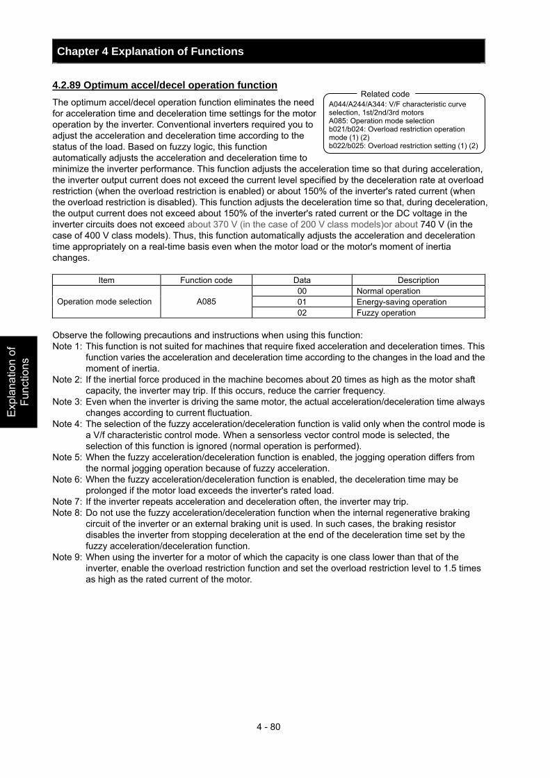
Chapter 4 Explanation of Functions
4 - 80
Exp
lana
tion
of
Func
tions
4.2.89 Optimum accel/decel operation function The optimum accel/decel operation function eliminates the need for acceleration time and deceleration time settings for the motor operation by the inverter. Conventional inverters required you to adjust the acceleration and deceleration time according to the status of the load. Based on fuzzy logic, this function automatically adjusts the acceleration and deceleration time to minimize the inverter performance. This function adjusts the acceleration time so that during acceleration, the inverter output current does not exceed the current level specified by the deceleration rate at overload restriction (when the overload restriction is enabled) or about 150% of the inverter's rated current (when the overload restriction is disabled). This function adjusts the deceleration time so that, during deceleration, the output current does not exceed about 150% of the inverter's rated current or the DC voltage in the inverter circuits does not exceed about 370 V (in the case of 200 V class models)or about 740 V (in the case of 400 V class models). Thus, this function automatically adjusts the acceleration and deceleration time appropriately on a real-time basis even when the motor load or the motor's moment of inertia changes.
Item Function code Data Description 00 Normal operation 01 Energy-saving operation Operation mode selection A085 02 Fuzzy operation
Observe the following precautions and instructions when using this function: Note 1: This function is not suited for machines that require fixed acceleration and deceleration times. This
function varies the acceleration and deceleration time according to the changes in the load and the moment of inertia.
Note 2: If the inertial force produced in the machine becomes about 20 times as high as the motor shaft capacity, the inverter may trip. If this occurs, reduce the carrier frequency.
Note 3: Even when the inverter is driving the same motor, the actual acceleration/deceleration time always changes according to current fluctuation.
Note 4: The selection of the fuzzy acceleration/deceleration function is valid only when the control mode is a V/f characteristic control mode. When a sensorless vector control mode is selected, the selection of this function is ignored (normal operation is performed).
Note 5: When the fuzzy acceleration/deceleration function is enabled, the jogging operation differs from the normal jogging operation because of fuzzy acceleration.
Note 6: When the fuzzy acceleration/deceleration function is enabled, the deceleration time may be prolonged if the motor load exceeds the inverter's rated load.
Note 7: If the inverter repeats acceleration and deceleration often, the inverter may trip. Note 8: Do not use the fuzzy acceleration/deceleration function when the internal regenerative braking
circuit of the inverter or an external braking unit is used. In such cases, the braking resistor disables the inverter from stopping deceleration at the end of the deceleration time set by the fuzzy acceleration/deceleration function.
Note 9: When using the inverter for a motor of which the capacity is one class lower than that of the inverter, enable the overload restriction function and set the overload restriction level to 1.5 times as high as the rated current of the motor.
A044/A244/A344: V/F characteristic curve selection, 1st/2nd/3rd motors A085: Operation mode selection b021/b024: Overload restriction operation mode (1) (2) b022/b025: Overload restriction setting (1) (2)
Related code
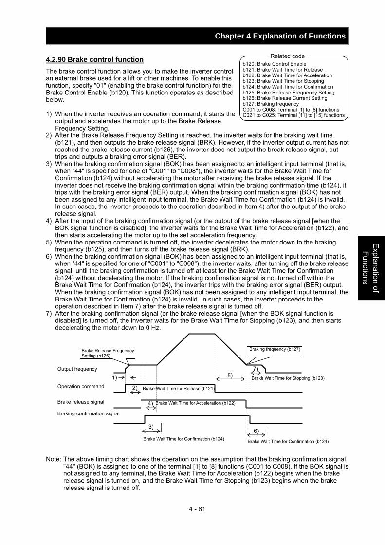
Chapter 4 Explanation of Functions
4 - 81
Explanation of Functions
4.2.90 Brake control function The brake control function allows you to make the inverter control an external brake used for a lift or other machines. To enable this function, specify "01" (enabling the brake control function) for the Brake Control Enable (b120). This function operates as described below. 1) When the inverter receives an operation command, it starts the
output and accelerates the motor up to the Brake Release Frequency Setting.
2) After the Brake Release Frequency Setting is reached, the inverter waits for the braking wait time (b121), and then outputs the brake release signal (BRK). However, if the inverter output current has not reached the brake release current (b126), the inverter does not output the break release signal, but trips and outputs a braking error signal (BER).
3) When the braking confirmation signal (BOK) has been assigned to an intelligent input terminal (that is, when "44" is specified for one of "C001" to "C008"), the inverter waits for the Brake Wait Time for Confirmation (b124) without accelerating the motor after receiving the brake release signal. If the inverter does not receive the braking confirmation signal within the braking confirmation time (b124), it trips with the braking error signal (BER) output. When the braking confirmation signal (BOK) has not been assigned to any intelligent input terminal, the Brake Wait Time for Confirmation (b124) is invalid. In such cases, the inverter proceeds to the operation described in Item 4) after the output of the brake release signal.
4) After the input of the braking confirmation signal (or the output of the brake release signal [when the BOK signal function is disabled], the inverter waits for the Brake Wait Time for Acceleration (b122), and then starts accelerating the motor up to the set acceleration frequency.
5) When the operation command is turned off, the inverter decelerates the motor down to the braking frequency (b125), and then turns off the brake release signal (BRK).
6) When the braking confirmation signal (BOK) has been assigned to an intelligent input terminal (that is, when "44" is specified for one of "C001" to "C008"), the inverter waits, after turning off the brake release signal, until the braking confirmation is turned off at least for the Brake Wait Time for Confirmation (b124) without decelerating the motor. If the braking confirmation signal is not turned off within the Brake Wait Time for Confirmation (b124), the inverter trips with the braking error signal (BER) output. When the braking confirmation signal (BOK) has not been assigned to any intelligent input terminal, the Brake Wait Time for Confirmation (b124) is invalid. In such cases, the inverter proceeds to the operation described in Item 7) after the brake release signal is turned off.
7) After the braking confirmation signal (or the brake release signal [when the BOK signal function is disabled] is turned off, the inverter waits for the Brake Wait Time for Stopping (b123), and then starts decelerating the motor down to 0 Hz.
Note: The above timing chart shows the operation on the assumption that the braking confirmation signal
"44" (BOK) is assigned to one of the terminal [1] to [8] functions (C001 to C008). If the BOK signal is not assigned to any terminal, the Brake Wait Time for Acceleration (b122) begins when the brake release signal is turned on, and the Brake Wait Time for Stopping (b123) begins when the brake release signal is turned off.
b120: Brake Control Enable b121: Brake Wait Time for Release b122: Brake Wait Time for Acceleration b123: Brake Wait Time for Stopping b124: Brake Wait Time for Confirmation b125: Brake Release Frequency Setting b126: Brake Release Current Setting b127: Braking frequency C001 to C008: Terminal [1] to [8] functions C021 to C025: Terminal [11] to [15] functions
Related code
2)
3)
4)
6)
7)1) 5)
Brake Release Frequency Setting (b125)
Braking frequency (b127)
Output frequency Operation command
Brake release signal Braking confirmation signal
Brake Wait Time for Release (b121)
Brake Wait Time for Acceleration (b122)
Brake Wait Time for Stopping (b123)
Brake Wait Time for Confirmation (b124) Brake Wait Time for Confirmation (b124)
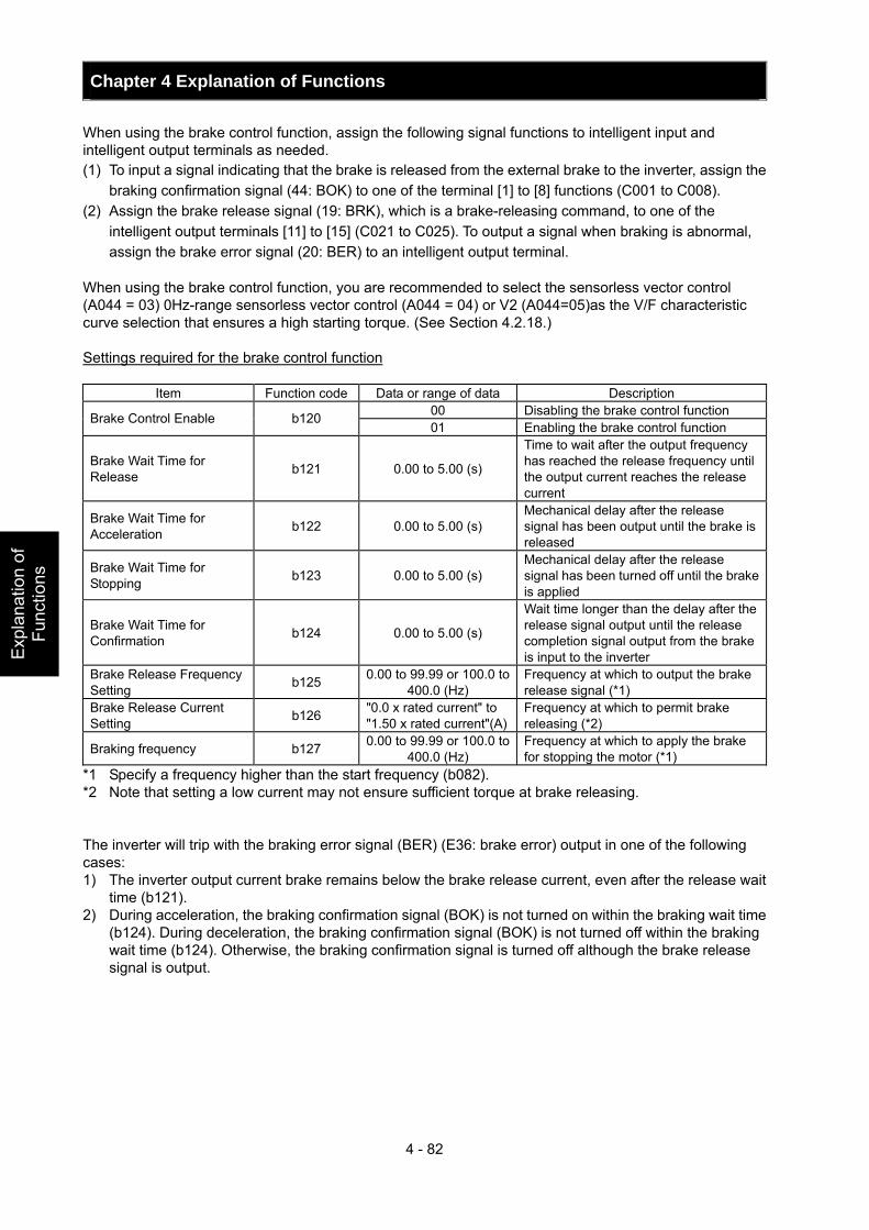
Chapter 4 Explanation of Functions
4 - 82
Exp
lana
tion
of
Func
tions
When using the brake control function, assign the following signal functions to intelligent input and intelligent output terminals as needed. (1) To input a signal indicating that the brake is released from the external brake to the inverter, assign the
braking confirmation signal (44: BOK) to one of the terminal [1] to [8] functions (C001 to C008). (2) Assign the brake release signal (19: BRK), which is a brake-releasing command, to one of the
intelligent output terminals [11] to [15] (C021 to C025). To output a signal when braking is abnormal, assign the brake error signal (20: BER) to an intelligent output terminal.
When using the brake control function, you are recommended to select the sensorless vector control (A044 = 03) 0Hz-range sensorless vector control (A044 = 04) or V2 (A044=05)as the V/F characteristic curve selection that ensures a high starting torque. (See Section 4.2.18.) Settings required for the brake control function
Item Function code Data or range of data Description 00 Disabling the brake control function Brake Control Enable b120 01 Enabling the brake control function
Brake Wait Time for Release b121 0.00 to 5.00 (s)
Time to wait after the output frequency has reached the release frequency until the output current reaches the release current
Brake Wait Time for Acceleration b122 0.00 to 5.00 (s)
Mechanical delay after the release signal has been output until the brake is released
Brake Wait Time for Stopping b123 0.00 to 5.00 (s)
Mechanical delay after the release signal has been turned off until the brake is applied
Brake Wait Time for Confirmation b124 0.00 to 5.00 (s)
Wait time longer than the delay after the release signal output until the release completion signal output from the brake is input to the inverter
Brake Release Frequency Setting b125 0.00 to 99.99 or 100.0 to
400.0 (Hz) Frequency at which to output the brake release signal (*1)
Brake Release Current Setting b126 "0.0 x rated current" to
"1.50 x rated current"(A)Frequency at which to permit brake releasing (*2)
Braking frequency b127 0.00 to 99.99 or 100.0 to 400.0 (Hz)
Frequency at which to apply the brake for stopping the motor (*1)
*1 Specify a frequency higher than the start frequency (b082). *2 Note that setting a low current may not ensure sufficient torque at brake releasing. The inverter will trip with the braking error signal (BER) (E36: brake error) output in one of the following cases: 1) The inverter output current brake remains below the brake release current, even after the release wait
time (b121). 2) During acceleration, the braking confirmation signal (BOK) is not turned on within the braking wait time
(b124). During deceleration, the braking confirmation signal (BOK) is not turned off within the braking wait time (b124). Otherwise, the braking confirmation signal is turned off although the brake release signal is output.
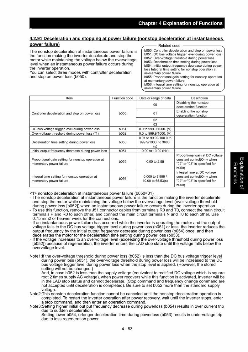
Chapter 4 Explanation of Functions
4 - 83
Explanation of Functions
4.2.91 Deceleration and stopping at power failure (nonstop deceleration at instantaneous power failure) The nonstop deceleration at instantaneous power failure is the function making the inverter decelerate and stop the motor while maintaining the voltage below the overvoltage level when an instantaneous power failure occurs during the inverter operation. You can select three modes with controller deceleration and stop on power loss (b050).
Item Function code Data or range of data Description
00 Disabling the nonstop deceleration function
01 Enabling the nonstop deceleration function
02
Controller deceleration and stop on power loss b050
03 DC bus voltage trigger level during power loss b051 0.0 to 999.9/1000. (V) Over-voltage threshold during power loss (*1) b052 0.0 to 999.9/1000. (V)
Deceleration time setting during power loss b053 0.01 to 99.99/100.0 to 999.9/1000. to 3600.
(s)
Initial output frequency decrease during power loss b054 0.00 to 10.00 (Hz)
Proportional gain setting for nonstop operation at momentary power failure b055 0.00 to 2.55
Proportional gain at DC voltage constant control(Only when "02" or "03" is specified for b050)
Integral time setting for nonstop operation at momentary power failure b056 0.000 to 9.999 /
10.00 to 65.53(s)
Integral time at DC voltage constant control(Only when "02" or "03" is specified for b050)
<1> nonstop deceleration at instantaneous power failure (b050=01) - The nonstop deceleration at instantaneous power failure is the function making the inverter decelerate
and stop the motor while maintaining the voltage below the overvoltage level (over-voltage threshold during power loss [b052]) when an instantaneous power failure occurs during the inverter operation.
- To use this function, remove the J51 connector cables from terminals R0 and T0, connect the main circuit terminals P and R0 to each other, and connect the main circuit terminals N and T0 to each other. Use 0.75 mm2 or heavier wires for the connections.
- If an instantaneous power failure has occurred while the inverter is operating the motor and the output voltage falls to the DC bus voltage trigger level during power loss (b051) or less, the inverter reduces the output frequency by the initial output frequency decrease during power loss (b054) once, and then decelerates the motor for the deceleration time setting during power loss (b053).
- If the voltage increases to an overvoltage level (exceeding the over-voltage threshold during power loss [b052]) because of regeneration, the inverter enters the LAD stop state until the voltage falls below the overvoltage level.
Note1:If the over-voltage threshold during power loss (b052) is less than the DC bus voltage trigger level
during power loss (b051), the over-voltage threshold during power loss will be increased to the DC bus voltage trigger level during power loss when the stop level is applied. (However, the stored setting will not be changed.) And, in case b052 is less than the supply voltage (equivalent to rectified DC voltage which is square root 2 times supply AC voltage), when power recovers while this function is activated, inverter will be in the LAD stop status and cannot decelerate. (Stop command and frequency change command are not accepted until deceleration is completed). Be sure to set b052 more than the standard supply voltage.
Note2:This nonstop deceleration function cannot be canceled until the nonstop deceleration operation is completed. To restart the inverter operation after power recovery, wait until the inverter stops, enter a stop command, and then enter an operation command.
Note3:Setting higher initial out put frequency decrease during powerloss (b054) results in over current trip due to sudden deceleration. Setting lower b054, orlonger deceleration time during powerloss (b053) results in undervoltage trip due to less regeneration power.
b050: Controller deceleration and stop on power loss b051: DC bus voltage trigger level during power loss b052: Over-voltage threshold during power loss b053: Deceleration time setting during power loss b054: Initial output frequency decrease during power loss Integral time setting for nonstop operation at momentary power failure b055: Proportional gain setting for nonstop operation at momentary power failure b056: Integral time setting for nonstop operation at momentary power failure
Related code
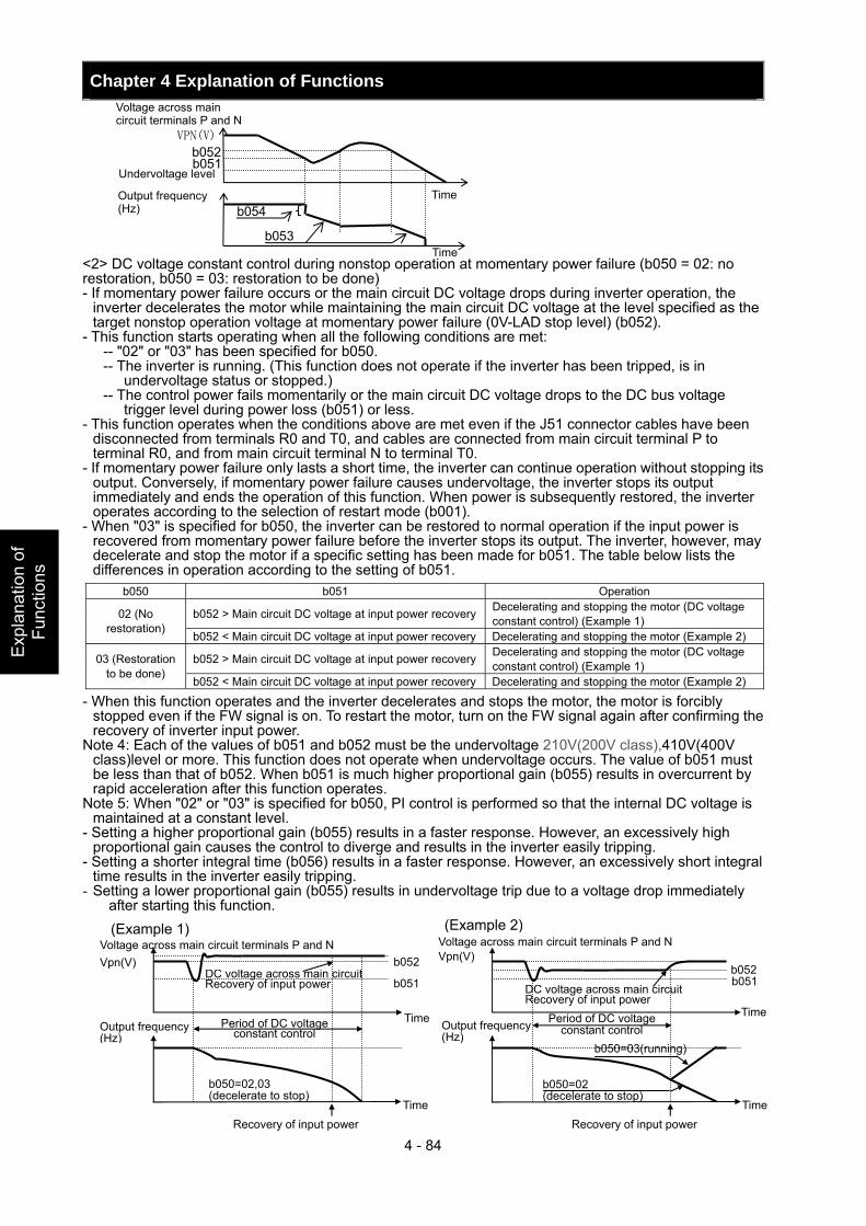
Chapter 4 Explanation of Functions
4 - 84
Exp
lana
tion
of
Func
tions
<2> DC voltage constant control during nonstop operation at momentary power failure (b050 = 02: no restoration, b050 = 03: restoration to be done) - If momentary power failure occurs or the main circuit DC voltage drops during inverter operation, the
inverter decelerates the motor while maintaining the main circuit DC voltage at the level specified as the target nonstop operation voltage at momentary power failure (0V-LAD stop level) (b052).
- This function starts operating when all the following conditions are met: -- "02" or "03" has been specified for b050. -- The inverter is running. (This function does not operate if the inverter has been tripped, is in
undervoltage status or stopped.) -- The control power fails momentarily or the main circuit DC voltage drops to the DC bus voltage
trigger level during power loss (b051) or less. - This function operates when the conditions above are met even if the J51 connector cables have been
disconnected from terminals R0 and T0, and cables are connected from main circuit terminal P to terminal R0, and from main circuit terminal N to terminal T0.
- If momentary power failure only lasts a short time, the inverter can continue operation without stopping its output. Conversely, if momentary power failure causes undervoltage, the inverter stops its output immediately and ends the operation of this function. When power is subsequently restored, the inverter operates according to the selection of restart mode (b001).
- When "03" is specified for b050, the inverter can be restored to normal operation if the input power is recovered from momentary power failure before the inverter stops its output. The inverter, however, may decelerate and stop the motor if a specific setting has been made for b051. The table below lists the differences in operation according to the setting of b051.
b050 b051 Operation
b052 > Main circuit DC voltage at input power recovery Decelerating and stopping the motor (DC voltage constant control) (Example 1) 02 (No
restoration) b052 < Main circuit DC voltage at input power recovery Decelerating and stopping the motor (Example 2)
b052 > Main circuit DC voltage at input power recovery Decelerating and stopping the motor (DC voltage constant control) (Example 1) 03 (Restoration
to be done) b052 < Main circuit DC voltage at input power recovery Decelerating and stopping the motor (Example 2)
- When this function operates and the inverter decelerates and stops the motor, the motor is forcibly stopped even if the FW signal is on. To restart the motor, turn on the FW signal again after confirming the recovery of inverter input power.
Note 4: Each of the values of b051 and b052 must be the undervoltage 210V(200V class),410V(400V class)level or more. This function does not operate when undervoltage occurs. The value of b051 must be less than that of b052. When b051 is much higher proportional gain (b055) results in overcurrent by rapid acceleration after this function operates.
Note 5: When "02" or "03" is specified for b050, PI control is performed so that the internal DC voltage is maintained at a constant level.
- Setting a higher proportional gain (b055) results in a faster response. However, an excessively high proportional gain causes the control to diverge and results in the inverter easily tripping.
- Setting a shorter integral time (b056) results in a faster response. However, an excessively short integral time results in the inverter easily tripping.
- Setting a lower proportional gain (b055) results in undervoltage trip due to a voltage drop immediately after starting this function.
b052 b051
b053
b054
VPN(V)
Voltage across main circuit terminals P and N
Undervoltage level
Output frequency (Hz)
Time
Time ( )
b050=02(decelerate to stop)
Period of DC voltage constant control
Voltage across main circuit terminals P and N Vpn(V)
Time
Time
Output frequency(Hz)
b050=03(running)
b052b051
Voltage across main circuit terminals P and N Vpn(V)
Time
Time
Output frequency (Hz)
Period of DC voltage constant control
b050=02,03 (decelerate to stop)
DC voltage across main circuitRecovery of input power
b052
b051
(Example 1) (Example 2)
DC voltage across main circuit Recovery of input power
Recovery of input power Recovery of input power
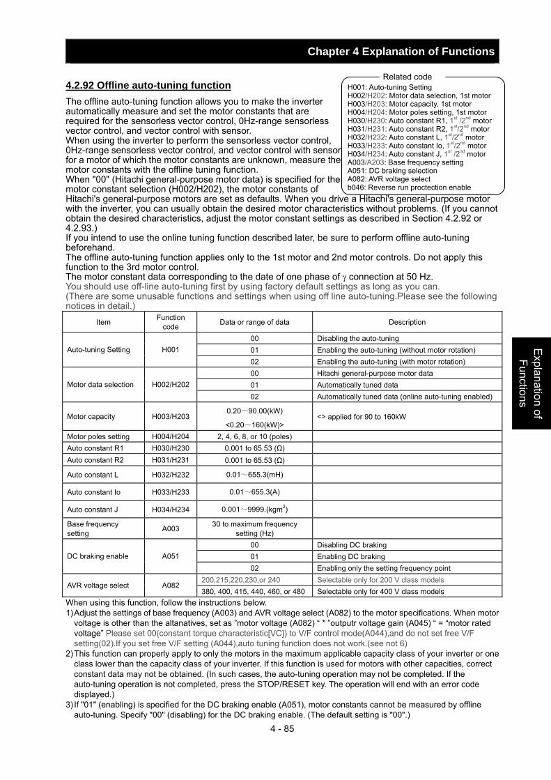
Chapter 4 Explanation of Functions
4 - 85
Explanation of Functions
4.2.92 Offline auto-tuning function The offline auto-tuning function allows you to make the inverter automatically measure and set the motor constants that are required for the sensorless vector control, 0Hz-range sensorless vector control, and vector control with sensor. When using the inverter to perform the sensorless vector control, 0Hz-range sensorless vector control, and vector control with sensor for a motor of which the motor constants are unknown, measure the motor constants with the offline tuning function. When "00" (Hitachi general-purpose motor data) is specified for the motor constant selection (H002/H202), the motor constants of Hitachi's general-purpose motors are set as defaults. When you drive a Hitachi's general-purpose motor with the inverter, you can usually obtain the desired motor characteristics without problems. (If you cannot obtain the desired characteristics, adjust the motor constant settings as described in Section 4.2.92 or 4.2.93.) If you intend to use the online tuning function described later, be sure to perform offline auto-tuning beforehand. The offline auto-tuning function applies only to the 1st motor and 2nd motor controls. Do not apply this function to the 3rd motor control. The motor constant data corresponding to the date of one phase of γ connection at 50 Hz. You should use off-line auto-tuning first by using factory default settings as long as you can. (There are some unusable functions and settings when using off line auto-tuning.Please see the following notices in detail.)
Item Function code Data or range of data Description
00 Disabling the auto-tuning 01 Enabling the auto-tuning (without motor rotation) Auto-tuning Setting H001 02 Enabling the auto-tuning (with motor rotation) 00 Hitachi general-purpose motor data 01 Automatically tuned data Motor data selection H002/H202 02 Automatically tuned data (online auto-tuning enabled)
Motor capacity H003/H203 0.20~90.00(kW)
<0.20~160(kW)> <> applied for 90 to 160kW
Motor poles setting H004/H204 2, 4, 6, 8, or 10 (poles) Auto constant R1 H030/H230 0.001 to 65.53 (Ω) Auto constant R2 H031/H231 0.001 to 65.53 (Ω)
Auto constant L H032/H232 0.01~655.3(mH)
Auto constant Io H033/H233 0.01~655.3(A)
Auto constant J H034/H234 0.001~9999.(kgm2)
Base frequency setting A003 30 to maximum frequency
setting (Hz)
00 Disabling DC braking 01 Enabling DC braking DC braking enable A051 02 Enabling only the setting frequency point
200,215,220,230,or 240 Selectable only for 200 V class models AVR voltage select A082
380, 400, 415, 440, 460, or 480 Selectable only for 400 V class models When using this function, follow the instructions below. 1) Adjust the settings of base frequency (A003) and AVR voltage select (A082) to the motor specifications. When motor
voltage is other than the altanatives, set as ”motor voltage (A082) “ * ”outputr voltage gain (A045) “ = “motor rated voltage” Please set 00(constant torque characteristic[VC]) to V/F control mode(A044),and do not set free V/F setting(02).If you set free V/F setting (A044),auto tuning function does not work.(see not 6)
2) This function can properly apply to only the motors in the maximum applicable capacity class of your inverter or one class lower than the capacity class of your inverter. If this function is used for motors with other capacities, correct constant data may not be obtained. (In such cases, the auto-tuning operation may not be completed. If the auto-tuning operation is not completed, press the STOP/RESET key. The operation will end with an error code displayed.)
3) If "01" (enabling) is specified for the DC braking enable (A051), motor constants cannot be measured by offline auto-tuning. Specify "00" (disabling) for the DC braking enable. (The default setting is "00".)
H001: Auto-tuning Setting H002/H202: Motor data selection, 1st motor H003/H203: Motor capacity, 1st motor H004/H204: Motor poles setting, 1st motor H030/H230: Auto constant R1, 1st /2nd motor H031/H231: Auto constant R2, 1st/2nd motor H032/H232: Auto constant L, 1st/2nd motor H033/H233: Auto constant Io, 1st/2nd motor H034/H234: Auto constant J, 1st /2nd motor A003/A203: Base frequency setting A051: DC braking selection A082: AVR voltage select b046: Reverse run proctection enable
Related code
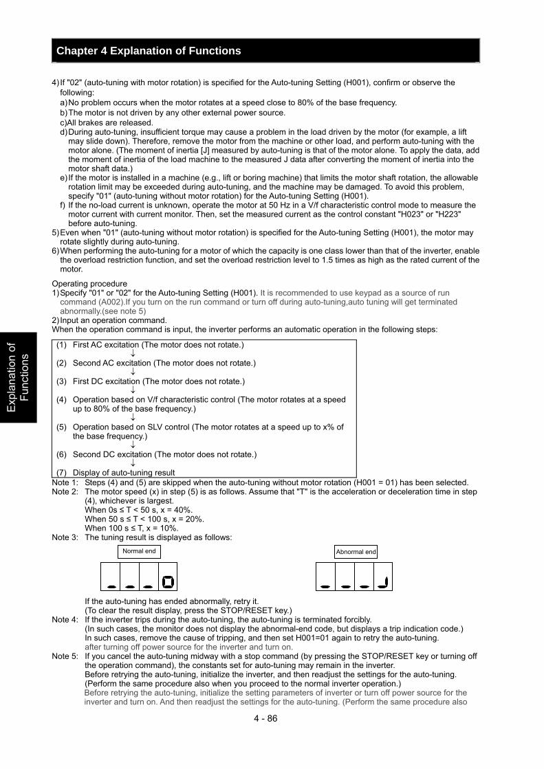
Chapter 4 Explanation of Functions
4 - 86
Exp
lana
tion
of
Func
tions
4) If "02" (auto-tuning with motor rotation) is specified for the Auto-tuning Setting (H001), confirm or observe the following: a) No problem occurs when the motor rotates at a speed close to 80% of the base frequency. b) The motor is not driven by any other external power source. c)All brakes are released. d) During auto-tuning, insufficient torque may cause a problem in the load driven by the motor (for example, a lift
may slide down). Therefore, remove the motor from the machine or other load, and perform auto-tuning with the motor alone. (The moment of inertia [J] measured by auto-tuning is that of the motor alone. To apply the data, add the moment of inertia of the load machine to the measured J data after converting the moment of inertia into the motor shaft data.)
e) If the motor is installed in a machine (e.g., lift or boring machine) that limits the motor shaft rotation, the allowable rotation limit may be exceeded during auto-tuning, and the machine may be damaged. To avoid this problem, specify "01" (auto-tuning without motor rotation) for the Auto-tuning Setting (H001).
f) If the no-load current is unknown, operate the motor at 50 Hz in a V/f characteristic control mode to measure the motor current with current monitor. Then, set the measured current as the control constant "H023" or "H223" before auto-tuning.
5) Even when "01" (auto-tuning without motor rotation) is specified for the Auto-tuning Setting (H001), the motor may rotate slightly during auto-tuning.
6) When performing the auto-tuning for a motor of which the capacity is one class lower than that of the inverter, enable the overload restriction function, and set the overload restriction level to 1.5 times as high as the rated current of the motor.
Operating procedure 1) Specify "01" or "02" for the Auto-tuning Setting (H001). It is recommended to use keypad as a source of run
command (A002).If you turn on the run command or turn off during auto-tuning,auto tuning will get terminated abnormally.(see note 5)
2) Input an operation command. When the operation command is input, the inverter performs an automatic operation in the following steps:
(1) First AC excitation (The motor does not rotate.) ↓ (2) Second AC excitation (The motor does not rotate.) ↓ (3) First DC excitation (The motor does not rotate.) ↓ (4) Operation based on V/f characteristic control (The motor rotates at a speed
up to 80% of the base frequency.) ↓ (5) Operation based on SLV control (The motor rotates at a speed up to x% of
the base frequency.) ↓ (6) Second DC excitation (The motor does not rotate.) ↓ (7) Display of auto-tuning result
Note 1: Steps (4) and (5) are skipped when the auto-tuning without motor rotation (H001 = 01) has been selected. Note 2: The motor speed (x) in step (5) is as follows. Assume that "T" is the acceleration or deceleration time in step
(4), whichever is largest. When 0s ≤ T < 50 s, x = 40%. When 50 s ≤ T < 100 s, x = 20%. When 100 s ≤ T, x = 10%. Note 3: The tuning result is displayed as follows: If the auto-tuning has ended abnormally, retry it. (To clear the result display, press the STOP/RESET key.) Note 4: If the inverter trips during the auto-tuning, the auto-tuning is terminated forcibly. (In such cases, the monitor does not display the abnormal-end code, but displays a trip indication code.) In such cases, remove the cause of tripping, and then set H001=01 again to retry the auto-tuning.
after turning off power source for the inverter and turn on. Note 5: If you cancel the auto-tuning midway with a stop command (by pressing the STOP/RESET key or turning off
the operation command), the constants set for auto-tuning may remain in the inverter. Before retrying the auto-tuning, initialize the inverter, and then readjust the settings for the auto-tuning.
(Perform the same procedure also when you proceed to the normal inverter operation.) Before retrying the auto-tuning, initialize the setting parameters of inverter or turn off power source for the inverter and turn on. And then readjust the settings for the auto-tuning. (Perform the same procedure also
Normal end Abnormal end
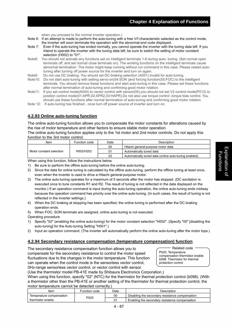
Chapter 4 Explanation of Functions
4 - 87
Explanation of Functions
when you proceed to the normal inverter operation.) Note 6: If an attempt is made to perform the auto-tuning with a free V/f characteristic selected as the control mode,
the inverter will soon terminate the operation with the abnormal-end code displayed. Note 7: Even if the auto-tuning has ended normally, you cannot operate the inverter with the tuning data left. If you
intend to operate the inverter with the tuning data left, be sure to switch the setting of motor constant selection (H002) to "01".
Note8: You should not activate any functions set on intelligent terminals 1-8 during auto- tuning. (Set normal open terminals off, and set normal close terminals on). The working functions on the intelligent terminals cause abnormal termination. The motor might keep running without run command in this case. Please restart auto- tuning after turning off power source for the inverter and turn on again.
Note9: Do not use DC braking. You should set DC-braking selection (A051) invalid for auto-tuning. Note10: Do not start auto-tuning with setting servo-on(54:SON )and forcing function(55:FOC) to the intelligent
terminals. You should remove these functions and start auto-tuning in this case. Please set these functions after normal termination of auto-tuning and confirming good motor rotation.
Note11: If you set control mode(A044) to vector control with sensor(05),you should not set V2 control mode(P012) to position control mode(01:APR,02:APR2,03:HAPR).Do not also use torque control ,torque bias control. You should use these functions after normal termination of auto-tuning and confirming good motor rotation.
Note 12: If auto-tuning has finished , once turn off power source of inverter and turn on.
4.2.93 Online auto-tuning function The online auto-tuning function allows you to compensate the motor constants for alterations caused by the rise of motor temperature and other factors to ensure stable motor operation. The online auto-tuning function applies only to the 1st motor and 2nd motor controls. Do not apply this function to the 3rd motor control.
Item Function code Data Description 00 Hitachi general-purpose motor data 01 Automatically tuned data Motor constant selection H002/H202 02 Automatically tuned data (online auto-tuning enabled)
When using this function, follow the instructions below. 1) Be sure to perform the offline auto-tuning before the online auto-tuning. 2) Since the data for online tuning is calculated by the offline auto-tuning, perform the offline tuning at least once,
even when the inverter is used to drive a Hitachi general-purpose motor. 3) The online auto-tuning operates for a maximum of 5 seconds after the motor has stopped. (DC excitation is
executed once to tune constants R1 and R2. The result of tuning is not reflected in the data displayed on the monitor.) If an operation command is input during the auto-tuning operation, the online auto-tuning ends midway because the operation command has priority over the online auto-tuning. (In such cases, the result of tuning is not reflected in the inverter settings.)
4) When the DC braking at stopping has been specified, the online tuning is performed after the DC braking operation ends.
5) When FOC, SON terminals are assigned, online auto-tuning is not executed. Operating procedure 1) Specify "02" (enabling the online auto-tuning) for the motor constant selection "H002". (Specify "00" [disabling the
auto-tuning] for the Auto-tuning Setting "H001".) 2) Input an operation command. (The inverter will automatically perform the online auto-tuning after the motor tops.) 4.2.94 Secondary resistance compensation (temperature compensation) function The secondary resistance compensation function allows you to compensate for the secondary resistance to control the motor speed fluctuations due to the changes in the motor temperature. This function can operate when the control mode is the sensorless vector control, 0Hz-range sensorless vector control, or vector control with sensor. (Use the thermistor model PB-41E made by Shibaura Electronics Corporation.) When using this function, specify "02" (NTC) for the thermistor for thermal protection control (b098). (With a thermistor other than the PB-41E or another setting of the thermistor for thermal protection control, the motor temperature cannot be detected correctly.)
Item Function code Data Description 00 Disabling the secondary resistance compensation Temperature compensation
thermistor enable P025
01 Enabling the secondary resistance compensation
P025: Temperature compensation thermistor enableb098: Thermistor for thermal protection control
Related code
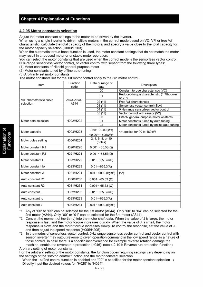
Chapter 4 Explanation of Functions
4 - 88
Exp
lana
tion
of
Func
tions
4.2.95 Motor constants selection Adjust the motor constant settings to the motor to be driven by the inverter. When using a single inverter to drive multiple motors in the control mode based on VC, VP, or free V/f characteristic, calculate the total capacity of the motors, and specify a value close to the total capacity for the motor capacity selection (H003/H203). When the automatic torque boost function is used, the motor constant settings that do not match the motor may result in a reduced motor or unstable motor operation. You can select the motor constants that are used when the control mode is the sensorless vector control, 0Hz-range sensorless vector control, or vector control with sensor from the following three types: (1) Motor constants of Hitachi general-purpose motor (2) Motor constants tuned by offline auto-tuning (3) Arbitrarily set motor constants The motor constants set for the 1st motor control apply to the 3rd motor control.
Item Function code
Data or range of data Description
00 Constant torque characteristic (VC)
01 Reduced-torque characteristic (1.7thpower of VP)
02 (*1) Free V/f characteristic 03 (*1) Sensorless vector control (SLV) 04 (*1) 0 Hz-range sensorless vector control
V/F characteristic curve selection
A044/A244/ A344
05 (*1) Vector control with sensor (V2) 00 Hitachi general-purpose motor onstants 01 Motor constants tuned by auto-tuning Motor data selection H002/H202 02 Motor constants tuned by online auto-tuning
Motor capacity H003/H203 0.20~90.00(kW) <0.20~160(kW)>
<> applied for 90 to 160kW
Motor poles setting H004/H204 2, 4, 6, 8, or 10 (poles)
Motor constant R1 H020/H220 0.001~65.53(Ω)
Motor constant R2 H021/H221 0.001~65.53(Ω)
Motor constant L H022/H222 0.01~655.3(mH)
Motor constant Io H023/H223 0.01~655.3(A)
Motor constant J H024/H224 0.001~9999.(kgm2) (*2)
Auto constant R1 H030/H230 0.001~65.53 (Ω)
Auto constant R2 H031/H231 0.001~65.53 (Ω)
Auto constant L H032/H232 0.01~655.3(mH)
Auto constant Io H033/H233 0.01~655.3(A)
Auto constant J H034/H234 0.001~9999.(kgm2)
*1 Any of "00" to "05" can be selected for the 1st motor (A044). Only "00" to "04" can be selected for the 2nd motor (A244). Only "00" or "01" can be selected for the 3rd motor (A344).
*2 Convert the moment of inertia (J) into the motor shaft data. When the value of J is large, the motor response is fast, and the motor torque increases quickly. When the value of J is small, the motor response is slow, and the motor torque increases slowly. To control the response, set the value of J, and then adjust the speed response (H005/H205).
*3 In the modes of sensorless vector control, 0Hz-range sensorless vector control and vector control with sensor, inverter may output reverse to given operation command in the low speed range as a nature of those control. In case there is a specific inconvenience for example reverse rotation damage the machine, enable the reverse run protection (b046). (see 4.2.101: Reverse run protection function)
Arbitrary setting of motor constants For the arbitrary setting of the motor constants, the function codes requiring settings vary depending on the settings of the 1st/2nd control function and the motor constant selection. - When the 1st/2nd control function is enabled and "00" is specified for the motor constant selection →
Directly input the desired values for "H020" to "H024".
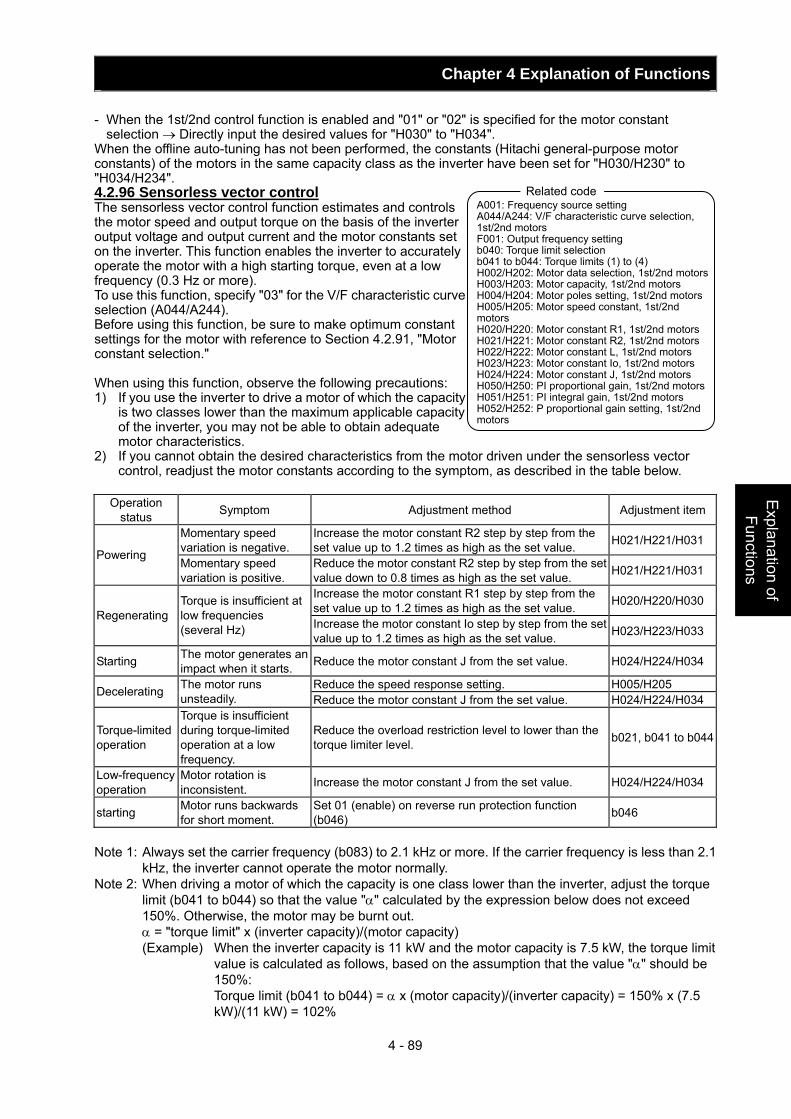
Chapter 4 Explanation of Functions
4 - 89
Explanation of Functions
- When the 1st/2nd control function is enabled and "01" or "02" is specified for the motor constant selection → Directly input the desired values for "H030" to "H034".
When the offline auto-tuning has not been performed, the constants (Hitachi general-purpose motor constants) of the motors in the same capacity class as the inverter have been set for "H030/H230" to "H034/H234". 4.2.96 Sensorless vector control The sensorless vector control function estimates and controls the motor speed and output torque on the basis of the inverter output voltage and output current and the motor constants set on the inverter. This function enables the inverter to accurately operate the motor with a high starting torque, even at a low frequency (0.3 Hz or more). To use this function, specify "03" for the V/F characteristic curve selection (A044/A244). Before using this function, be sure to make optimum constant settings for the motor with reference to Section 4.2.91, "Motor constant selection." When using this function, observe the following precautions: 1) If you use the inverter to drive a motor of which the capacity
is two classes lower than the maximum applicable capacity of the inverter, you may not be able to obtain adequate motor characteristics.
2) If you cannot obtain the desired characteristics from the motor driven under the sensorless vector control, readjust the motor constants according to the symptom, as described in the table below.
Operation
status Symptom Adjustment method Adjustment item
Momentary speed variation is negative.
Increase the motor constant R2 step by step from the set value up to 1.2 times as high as the set value. H021/H221/H031
Powering Momentary speed variation is positive.
Reduce the motor constant R2 step by step from the set value down to 0.8 times as high as the set value. H021/H221/H031
Increase the motor constant R1 step by step from the set value up to 1.2 times as high as the set value. H020/H220/H030
Regenerating Torque is insufficient at low frequencies (several Hz) Increase the motor constant Io step by step from the set
value up to 1.2 times as high as the set value. H023/H223/H033
Starting The motor generates an impact when it starts. Reduce the motor constant J from the set value. H024/H224/H034
Reduce the speed response setting. H005/H205 Decelerating The motor runs unsteadily. Reduce the motor constant J from the set value. H024/H224/H034
Torque-limited operation
Torque is insufficient during torque-limited operation at a low frequency.
Reduce the overload restriction level to lower than the torque limiter level. b021, b041 to b044
Low-frequency operation
Motor rotation is inconsistent. Increase the motor constant J from the set value. H024/H224/H034
starting Motor runs backwards for short moment.
Set 01 (enable) on reverse run protection function (b046) b046
Note 1: Always set the carrier frequency (b083) to 2.1 kHz or more. If the carrier frequency is less than 2.1
kHz, the inverter cannot operate the motor normally. Note 2: When driving a motor of which the capacity is one class lower than the inverter, adjust the torque
limit (b041 to b044) so that the value "α" calculated by the expression below does not exceed 150%. Otherwise, the motor may be burnt out.
α = "torque limit" x (inverter capacity)/(motor capacity) (Example) When the inverter capacity is 11 kW and the motor capacity is 7.5 kW, the torque limit
value is calculated as follows, based on the assumption that the value "α" should be 150%:
Torque limit (b041 to b044) = α x (motor capacity)/(inverter capacity) = 150% x (7.5 kW)/(11 kW) = 102%
A001: Frequency source setting A044/A244: V/F characteristic curve selection, 1st/2nd motors F001: Output frequency setting b040: Torque limit selection b041 to b044: Torque limits (1) to (4) H002/H202: Motor data selection, 1st/2nd motors H003/H203: Motor capacity, 1st/2nd motors H004/H204: Motor poles setting, 1st/2nd motors H005/H205: Motor speed constant, 1st/2nd motors H020/H220: Motor constant R1, 1st/2nd motors H021/H221: Motor constant R2, 1st/2nd motors H022/H222: Motor constant L, 1st/2nd motors H023/H223: Motor constant Io, 1st/2nd motors H024/H224: Motor constant J, 1st/2nd motors H050/H250: PI proportional gain, 1st/2nd motors H051/H251: PI integral gain, 1st/2nd motors H052/H252: P proportional gain setting, 1st/2nd motors
Related code
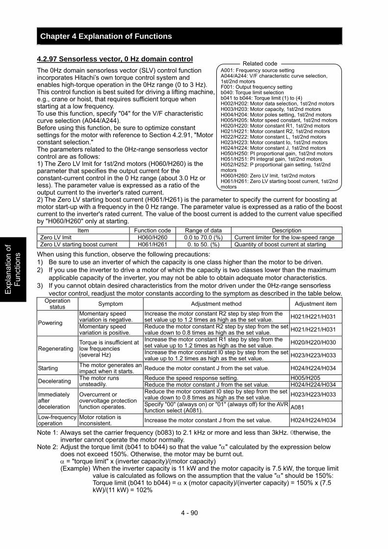
Chapter 4 Explanation of Functions
4 - 90
Exp
lana
tion
of
Func
tions
4.2.97 Sensorless vector, 0 Hz domain control The 0Hz domain sensorless vector (SLV) control function incorporates Hitachi’s own torque control system and enables high-torque operation in the 0Hz range (0 to 3 Hz). This control function is best suited for driving a lifting machine, e.g., crane or hoist, that requires sufficient torque when starting at a low frequency. To use this function, specify "04" for the V/F characteristic curve selection (A044/A244). Before using this function, be sure to optimize constant settings for the motor with reference to Section 4.2.91, "Motor constant selection." The parameters related to the 0Hz-range sensorless vector control are as follows: 1) The Zero LV lmit for 1st/2nd motors (H060/H260) is the parameter that specifies the output current for the constant-current control in the 0 Hz range (about 3.0 Hz or less). The parameter value is expressed as a ratio of the output current to the inverter's rated current. 2) The Zero LV starting boost current (H061/H261) is the parameter to specify the current for boosting at motor start-up with a frequency in the 0 Hz range. The parameter value is expressed as a ratio of the boost current to the inverter's rated current. The value of the boost current is added to the current value specified by "H060/H260" only at starting.
Item Function code Range of data Description Zero LV lmit H060/H260 0.0 to 70.0 (%) Current limiter for the low-speed range Zero LV starting boost current H061/H261 0. to 50. (%) Quantity of boost current at starting
When using this function, observe the following precautions: 1) Be sure to use an inverter of which the capacity is one class higher than the motor to be driven. 2) If you use the inverter to drive a motor of which the capacity is two classes lower than the maximum
applicable capacity of the inverter, you may not be able to obtain adequate motor characteristics. 3) If you cannot obtain desired characteristics from the motor driven under the 0Hz-range sensorless
vector control, readjust the motor constants according to the symptom as described in the table below. Operation
status Symptom Adjustment method Adjustment item
Momentary speed variation is negative.
Increase the motor constant R2 step by step from the set value up to 1.2 times as high as the set value. H021/H221/H031
Powering Momentary speed variation is positive.
Reduce the motor constant R2 step by step from the set value down to 0.8 times as high as the set value. H021/H221/H031
Increase the motor constant R1 step by step from the set value up to 1.2 times as high as the set value. H020/H220/H030
Regenerating Torque is insufficient at low frequencies (several Hz) Increase the motor constant I0 step by step from the set
value up to 1.2 times as high as the set value. H023/H223/H033
Starting The motor generates an impact when it starts. Reduce the motor constant J from the set value. H024/H224/H034
Reduce the speed response setting. H005/H205 Decelerating The motor runs unsteadily. Reduce the motor constant J from the set value. H024/H224/H034
Reduce the motor constant I0 step by step from the set value down to 0.8 times as high as the set value. H023/H223/H033 Immediately
after deceleration
Overcurrent or overvoltage protection function operates. Specify "00" (always on) or "01" (always off) for the AVR
function select (A081). A081
Low-frequency operation
Motor rotation is inconsistent. Increase the motor constant J from the set value. H024/H224/H034
Note 1: Always set the carrier frequency (b083) to 2.1 kHz or more and less than 3kHz. Otherwise, the inverter cannot operate the motor normally.
Note 2: Adjust the torque limit (b041 to b044) so that the value "α" calculated by the expression below does not exceed 150%. Otherwise, the motor may be burnt out.
α = "torque limit" x (inverter capacity)/(motor capacity) (Example) When the inverter capacity is 11 kW and the motor capacity is 7.5 kW, the torque limit
value is calculated as follows on the assumption that the value "α" should be 150%: Torque limit (b041 to b044) = α x (motor capacity)/(inverter capacity) = 150% x (7.5
kW)/(11 kW) = 102%
A001: Frequency source setting A044/A244: V/F characteristic curve selection, 1st/2nd motors F001: Output frequency setting b040: Torque limit selection b041 to b044: Torque limit (1) to (4) H002/H202: Motor data selection, 1st/2nd motors H003/H203: Motor capacity, 1st/2nd motors H004/H204: Motor poles setting, 1st/2nd motors H005/H205: Motor speed constant, 1st/2nd motorsH020/H220: Motor constant R1, 1st/2nd motors H021/H221: Motor constant R2, 1st/2nd motors H022/H222: Motor constant L, 1st/2nd motors H023/H223: Motor constant Io, 1st/2nd motors H024/H224: Motor constant J, 1st/2nd motors H050/H250: PI proportional gain, 1st/2nd motors H051/H251: PI integral gain, 1st/2nd motors H052/H252: P proportional gain setting, 1st/2nd motors H060/H260: Zero LV lmit, 1st/2nd motors H061/H261: Zero LV starting boost current, 1st/2nd motors
Related code
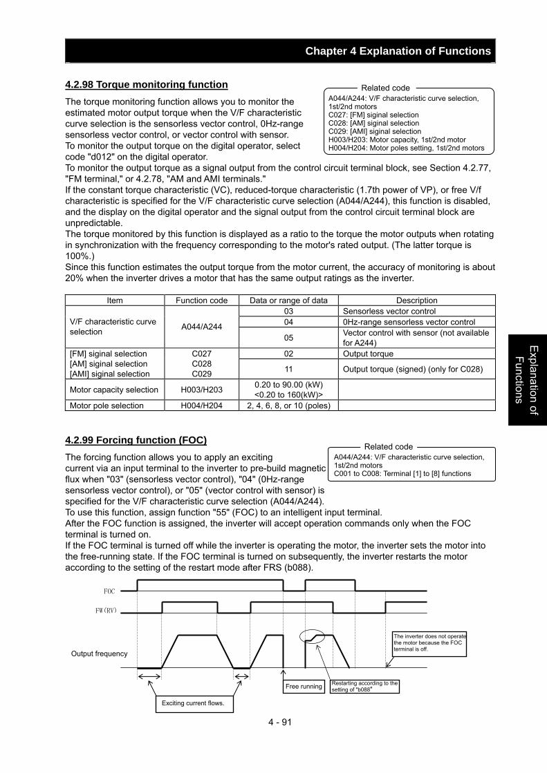
Chapter 4 Explanation of Functions
4 - 91
Explanation of Functions
4.2.98 Torque monitoring function The torque monitoring function allows you to monitor the estimated motor output torque when the V/F characteristic curve selection is the sensorless vector control, 0Hz-range sensorless vector control, or vector control with sensor. To monitor the output torque on the digital operator, select code "d012" on the digital operator. To monitor the output torque as a signal output from the control circuit terminal block, see Section 4.2.77, "FM terminal," or 4.2.78, "AM and AMI terminals." If the constant torque characteristic (VC), reduced-torque characteristic (1.7th power of VP), or free V/f characteristic is specified for the V/F characteristic curve selection (A044/A244), this function is disabled, and the display on the digital operator and the signal output from the control circuit terminal block are unpredictable. The torque monitored by this function is displayed as a ratio to the torque the motor outputs when rotating in synchronization with the frequency corresponding to the motor's rated output. (The latter torque is 100%.) Since this function estimates the output torque from the motor current, the accuracy of monitoring is about 20% when the inverter drives a motor that has the same output ratings as the inverter.
Item Function code Data or range of data Description 03 Sensorless vector control 04 0Hz-range sensorless vector control V/F characteristic curve
selection A044/A244 05 Vector control with sensor (not available
for A244) 02 Output torque [FM] siginal selection
[AM] siginal selection [AMI] siginal selection
C027 C028 C029 11 Output torque (signed) (only for C028)
Motor capacity selection H003/H203 0.20 to 90.00 (kW) <0.20 to 160(kW)>
Motor pole selection H004/H204 2, 4, 6, 8, or 10 (poles) 4.2.99 Forcing function (FOC) The forcing function allows you to apply an exciting current via an input terminal to the inverter to pre-build magnetic flux when "03" (sensorless vector control), "04" (0Hz-range sensorless vector control), or "05" (vector control with sensor) is specified for the V/F characteristic curve selection (A044/A244). To use this function, assign function "55" (FOC) to an intelligent input terminal. After the FOC function is assigned, the inverter will accept operation commands only when the FOC terminal is turned on. If the FOC terminal is turned off while the inverter is operating the motor, the inverter sets the motor into the free-running state. If the FOC terminal is turned on subsequently, the inverter restarts the motor according to the setting of the restart mode after FRS (b088).
A044/A244: V/F characteristic curve selection, 1st/2nd motors C027: [FM] siginal selection C028: [AM] siginal selection C029: [AMI] siginal selection H003/H203: Motor capacity, 1st/2nd motor H004/H204: Motor poles setting, 1st/2nd motors
Related code
A044/A244: V/F characteristic curve selection, 1st/2nd motors C001 to C008: Terminal [1] to [8] functions
Related code
FOC
FW(RV)
Output frequency
Exciting current flows.
The inverter does not operate the motor because the FOC terminal is off.
Free running Restarting according to the setting of "b088"
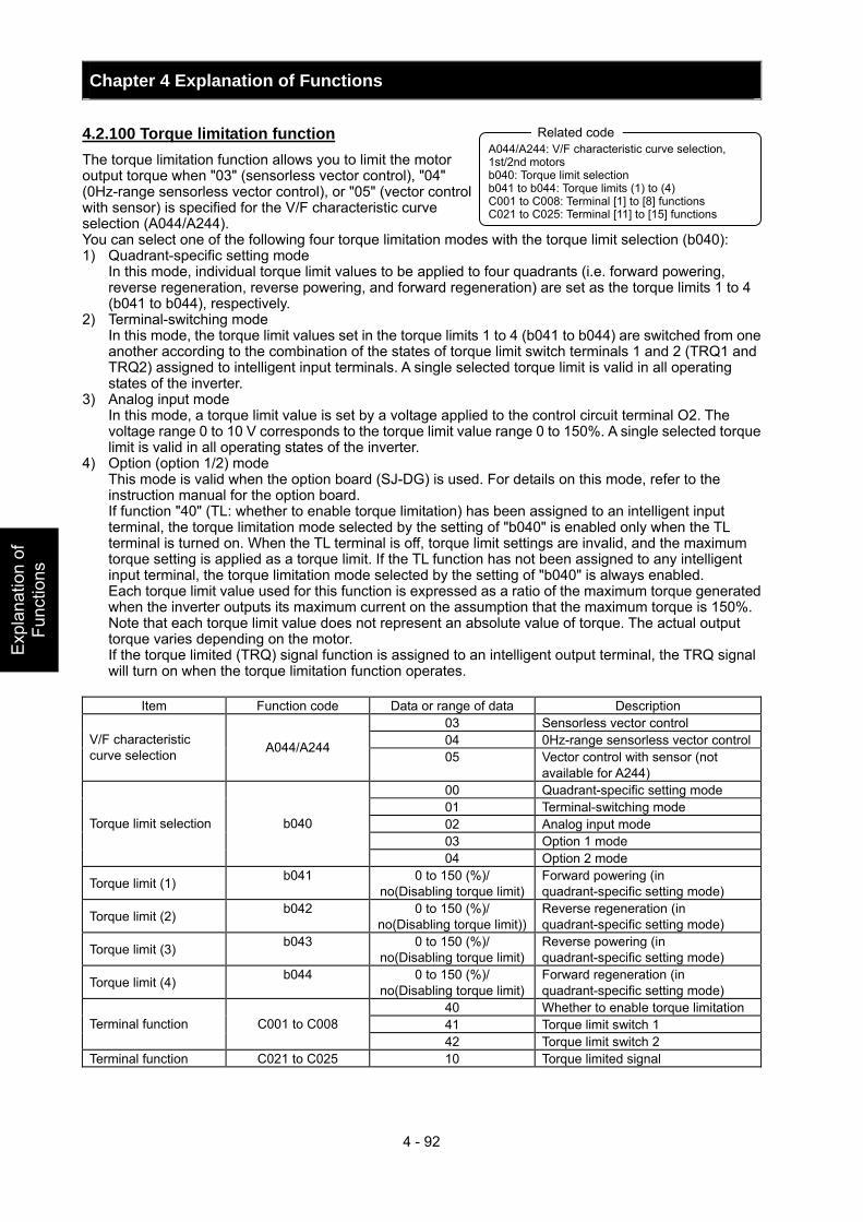
Chapter 4 Explanation of Functions
4 - 92
Exp
lana
tion
of
Func
tions
4.2.100 Torque limitation function The torque limitation function allows you to limit the motor output torque when "03" (sensorless vector control), "04" (0Hz-range sensorless vector control), or "05" (vector control with sensor) is specified for the V/F characteristic curve selection (A044/A244). You can select one of the following four torque limitation modes with the torque limit selection (b040): 1) Quadrant-specific setting mode In this mode, individual torque limit values to be applied to four quadrants (i.e. forward powering,
reverse regeneration, reverse powering, and forward regeneration) are set as the torque limits 1 to 4 (b041 to b044), respectively.
2) Terminal-switching mode In this mode, the torque limit values set in the torque limits 1 to 4 (b041 to b044) are switched from one
another according to the combination of the states of torque limit switch terminals 1 and 2 (TRQ1 and TRQ2) assigned to intelligent input terminals. A single selected torque limit is valid in all operating states of the inverter.
3) Analog input mode In this mode, a torque limit value is set by a voltage applied to the control circuit terminal O2. The
voltage range 0 to 10 V corresponds to the torque limit value range 0 to 150%. A single selected torque limit is valid in all operating states of the inverter.
4) Option (option 1/2) mode This mode is valid when the option board (SJ-DG) is used. For details on this mode, refer to the
instruction manual for the option board. If function "40" (TL: whether to enable torque limitation) has been assigned to an intelligent input terminal, the torque limitation mode selected by the setting of "b040" is enabled only when the TL terminal is turned on. When the TL terminal is off, torque limit settings are invalid, and the maximum torque setting is applied as a torque limit. If the TL function has not been assigned to any intelligent input terminal, the torque limitation mode selected by the setting of "b040" is always enabled. Each torque limit value used for this function is expressed as a ratio of the maximum torque generated when the inverter outputs its maximum current on the assumption that the maximum torque is 150%. Note that each torque limit value does not represent an absolute value of torque. The actual output torque varies depending on the motor. If the torque limited (TRQ) signal function is assigned to an intelligent output terminal, the TRQ signal will turn on when the torque limitation function operates.
Item Function code Data or range of data Description
03 Sensorless vector control 04 0Hz-range sensorless vector controlV/F characteristic
curve selection A044/A244 05 Vector control with sensor (not
available for A244) 00 Quadrant-specific setting mode 01 Terminal-switching mode 02 Analog input mode 03 Option 1 mode
Torque limit selection b040
04 Option 2 mode
Torque limit (1) b041 0 to 150 (%)/ no(Disabling torque limit)
Forward powering (in quadrant-specific setting mode)
Torque limit (2) b042 0 to 150 (%)/ no(Disabling torque limit))
Reverse regeneration (in quadrant-specific setting mode)
Torque limit (3) b043 0 to 150 (%)/ no(Disabling torque limit)
Reverse powering (in quadrant-specific setting mode)
Torque limit (4) b044 0 to 150 (%)/ no(Disabling torque limit)
Forward regeneration (in quadrant-specific setting mode)
40 Whether to enable torque limitation 41 Torque limit switch 1 Terminal function C001 to C008 42 Torque limit switch 2
Terminal function C021 to C025 10 Torque limited signal
A044/A244: V/F characteristic curve selection, 1st/2nd motors b040: Torque limit selection b041 to b044: Torque limits (1) to (4) C001 to C008: Terminal [1] to [8] functions C021 to C025: Terminal [11] to [15] functions
Related code
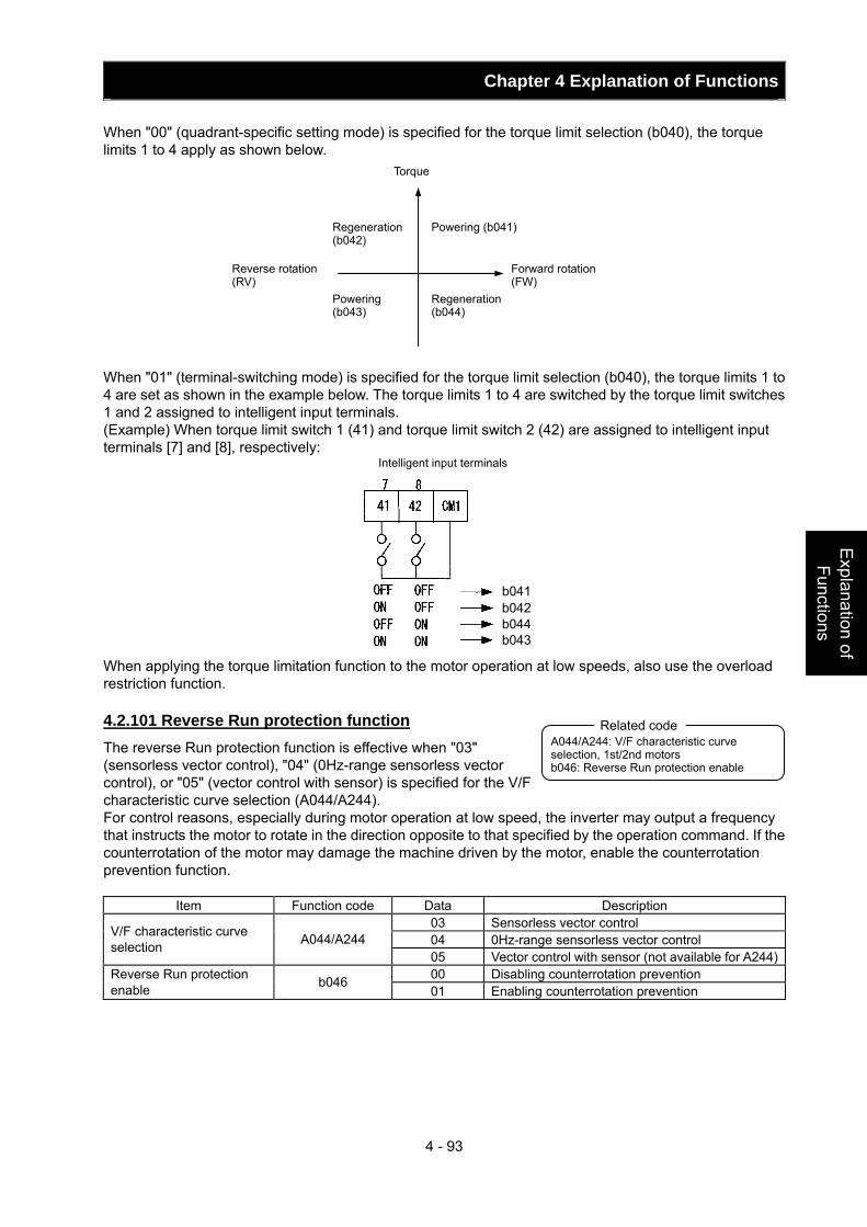
Chapter 4 Explanation of Functions
4 - 93
Explanation of Functions
When "00" (quadrant-specific setting mode) is specified for the torque limit selection (b040), the torque limits 1 to 4 apply as shown below. When "01" (terminal-switching mode) is specified for the torque limit selection (b040), the torque limits 1 to 4 are set as shown in the example below. The torque limits 1 to 4 are switched by the torque limit switches 1 and 2 assigned to intelligent input terminals. (Example) When torque limit switch 1 (41) and torque limit switch 2 (42) are assigned to intelligent input terminals [7] and [8], respectively:
When applying the torque limitation function to the motor operation at low speeds, also use the overload restriction function. 4.2.101 Reverse Run protection function The reverse Run protection function is effective when "03" (sensorless vector control), "04" (0Hz-range sensorless vector control), or "05" (vector control with sensor) is specified for the V/F characteristic curve selection (A044/A244). For control reasons, especially during motor operation at low speed, the inverter may output a frequency that instructs the motor to rotate in the direction opposite to that specified by the operation command. If the counterrotation of the motor may damage the machine driven by the motor, enable the counterrotation prevention function.
Item Function code Data Description 03 Sensorless vector control 04 0Hz-range sensorless vector control V/F characteristic curve
selection A044/A244 05 Vector control with sensor (not available for A244)00 Disabling counterrotation prevention Reverse Run protection
enable b046 01 Enabling counterrotation prevention
Torque
Regeneration (b042)
Powering (b043)
Powering (b041)
Regeneration (b044)
Reverse rotation (RV)
Forward rotation (FW)
Intelligent input terminals
A044/A244: V/F characteristic curve selection, 1st/2nd motors b046: Reverse Run protection enable
Related code
b041b042b044b043
Chapter 4 Explanation of Functions
4 - 94
Exp
lana
tion
of
Func
tions
4.2.102 Torque LAD stop function The torque LAD stop function is effective when "03" (sensorless vector control), "04" (0Hz-range sensorless vector control), or "05" (vector control with sensor) is specified for the V/F characteristic curve selection (A044/A244). This function temporarily stops the frequency-based deceleration function (LAD) when the torque limitation function operates.
Item Function code Data or range of data Description 03 Sensorless vector control 04 0Hz-range sensorless vector control V/F characteristic
curve selection A044/A244 05 Vector control with sensor (not available
for A244) 00 Quadrant-specific setting mode 01 Terminal-switching mode 02 Analog input mode 03 Option 1 mode
Torque limit selection b040
04 Option 2 mode
Torque limit (1) b041 0 to 150 (%)/no (disabling torque limitation)
Forward powering (in quadrant-specific setting mode)
Torque limit (2) b042 0 to 150 (%)/no (disabling torque limitation)
Reverse regeneration (in quadrant-specific setting mode)
Torque limit (3) b043 0 to 150 (%)/no (disabling torque limitation)
Reverse powering (in quadrant-specific setting mode)
Torque limit (4) b044 0 to 150 (%)/no (disabling torque limitation)
Forward regeneration (in quadrant-specific setting mode)
00 Disabling the torque LAD stop function Torque limit LADSTOP enable b045
01 Enabling the torque LAD stop function 40 Whether to enable torque limitation 41 Torque limit switch 1 Terminal function C001 to C008 42 Torque limit switch 2
4.2.103 High-torque multi-motor operation The high-torque multi-motor operation function allows you to make a single inverter operate the two motors (having the same specifications) that drive a single load (machine). This function is effective when the V/F characteristic curve selection is the sensorless vector control or 0Hz-range sensorless control. To use the function, adjust the inverter settings required for the sensorless vector control (see Section 4.2.92) or 0Hz-range sensorless control (see Section 4.2.93), except for the motor constant settings. Adjust the motor constants as follows: 1) For constants R1, R2, and L, specify a value half as large
as that normally specified for one motor. 2) For constant Io, specify a value twice as large as that
normally specified for one motor. 3) For constant J, specify a value half as large as the total
moment of inertia of the two motors and the load connected to them.
Select the motor capacity that is closest to the collective capacity of both motors. If different loads are driven by the two motors operated by the inverter, the load fluctuations on one motor may change the other motor's operation status, and the inverter may be unable to normally control the motors. Be sure to configure your system so that the motors drive only a single load or multiple loads that can, at least, be recognized as a single load.
A044/A244: V/F characteristic curve selection, 1st/2nd motors b040: Torque limit selection b041 to b044: Torque limits (1) to (4) b045: Torque limit LADSTOP enable
Related code
A044/A244: V/F characteristic curve selection, 1st/2nd motors F001: Output frequency setting b040: Torque limit selection b041 to b044: Torque limits (1) to (4) H002/H202: Motor data selection, 1st/2nd motors H003/H203: Motor capacity, 1st/2nd motors H004/H204: Motor poles setting, 1st/2nd motors H005/H205: Motor speed constant, 1st/2nd motors H020/H220: Motor constant R1, 1st/2nd motors H021/H221: Motor constant R2, 1st/2nd motors H022/H222: Motor constant L, 1st/2nd motors H023/H223: Motor constant Io, 1st/2nd motors H024/H224: Motor constant J, 1st/2nd motors H050/H250: PI proportional gain, 1st/2nd motors H051/H251: PI integral gain, 1st/2nd motors H052/H252: P proportional gain setting, 1st/2nd motors
Related code
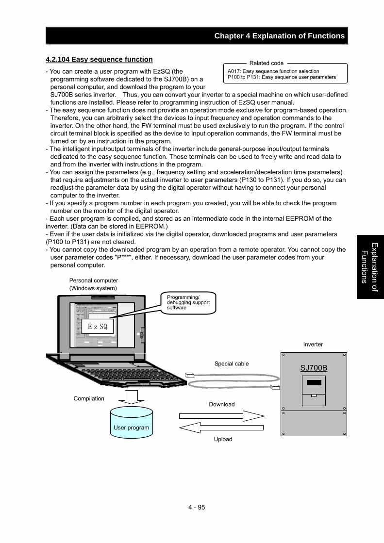
Chapter 4 Explanation of Functions
4 - 95
Explanation of Functions
4.2.104 Easy sequence function - You can create a user program with EzSQ (the
programming software dedicated to the SJ700B) on a personal computer, and download the program to your SJ700B series inverter. Thus, you can convert your inverter to a special machine on which user-defined functions are installed. Please refer to programming instruction of EzSQ user manual.
- The easy sequence function does not provide an operation mode exclusive for program-based operation. Therefore, you can arbitrarily select the devices to input frequency and operation commands to the inverter. On the other hand, the FW terminal must be used exclusively to run the program. If the control circuit terminal block is specified as the device to input operation commands, the FW terminal must be turned on by an instruction in the program.
- The intelligent input/output terminals of the inverter include general-purpose input/output terminals dedicated to the easy sequence function. Those terminals can be used to freely write and read data to and from the inverter with instructions in the program.
- You can assign the parameters (e.g., frequency setting and acceleration/deceleration time parameters) that require adjustments on the actual inverter to user parameters (P130 to P131). If you do so, you can readjust the parameter data by using the digital operator without having to connect your personal computer to the inverter.
- If you specify a program number in each program you created, you will be able to check the program number on the monitor of the digital operator.
- Each user program is compiled, and stored as an intermediate code in the internal EEPROM of the inverter. (Data can be stored in EEPROM.) - Even if the user data is initialized via the digital operator, downloaded programs and user parameters (P100 to P131) are not cleared. - You cannot copy the downloaded program by an operation from a remote operator. You cannot copy the
user parameter codes "P***", either. If necessary, download the user parameter codes from your personal computer.
A017: Easy sequence function selection P100 to P131: Easy sequence user parameters
Related code
SJ700B
Programming/debugging support software
EzSQ
Personal computer (Windows system)
Compilation
User program
Special cable
Download
Upload
Inverter
Chapter 4 Explanation of Functions
4 - 96
Exp
lana
tion
of
Func
tions
4.3 Functions Available When the Feedback Option Board (SJ-FB) Is Mounted
4.3.1 Functions requiring the SJ-FB - The feedback option board (SJ-FB) is generally required in the following cases: <1> When "05" (V2: vector control with sensor) is specified
for V/F characteristic curve selection, 1st motor(A044) <2> When pulse train frequency input is specified by one of
the following methods: - "06" (pulse train input) is specified for the run command source setting (A001). - "10" (operation function result) is specified for the run command source setting (A001), and "05"
(pulse train frequency) is specified for operation-target frequency selection 1 (A141) or operation-target frequency selection 2 (A142).
- "03" (pulse train frequency input) is specified for the PV source setting (A076). - For the wiring and DIP switch setting of the SJ-FB, refer to the instruction manual for the SJ-FB. - You can check the direction of motor rotation with the actual-frequency monitoring function
(d008). For checking with this monitoring function, specify "00" (VC) for the V/F characteristic curve selection (A044) and make the inverter operate the motor. (Normally, a positive frequency is monitored when a forward-operation command is input, and vice versa.)
4.3.2 V2 control pulse setting To use the V2 control pulse setting function, specify "00" (ASR: speed control mode) or "01" (APR: pulse train position control mode) for the control pulse setting (P012). In speed control mode, select a device to input frequency commands by the frequency source setting (A001). In pulse train position control mode, each frequency command is generated from a position command pulse train and the feedback of the position data detected by the encoder. The position command is input via an intelligent input terminal, to which the input of the pulse train position command is assigned. You can perform the position control with the command. Select one of three input formats for the pulse train position command by the pulse train mode setting (P013). To use the pulse train position control mode, assign function "48" (STAT) to an intelligent input terminal. The inverter accepts a pulse train position command only when the STAT terminal is on. You can clear the position deviation data by an external signal. Assign function "47" (PCLR) to an intelligent input terminal. Turning the PCLR on and off clears the position deviation data in the inverter. To output a speed deviation error signal, assign function "22" (DSE) to an intelligent input terminal, and specify a deviation level as the speed deviation error detection level (P027). If the deviation of the actual frequency (motor speed) from that specified by the frequency command exceeds the error detection level (P027), the inverter will output the DSE signal.
Item Function code Data or range of data Description 00 ASR: Speed control mode 01 APR: Pulse train position control mode 02 APR2: Absolute position control mode Control pulse setting P012
03 HAPR: High resolution absolute position control mode
00 MD0: 90°-phase-shift pulse train
01 MD1: Forward/reverse operation command with pulse train Pulse train mode setting (*2) P013
02 MD2: Forward-operation pulse train with reverse-operation pulse train
Encoder pulse-per-revolution (PPR) setting P011 128. to 9999. or 1000 to 6553 (10000
to 65535) (pulses) Pulse count of encoder
Position loop gain setting (*1) P023 0.00 to 99.99 or 100.0 (rad/s) Position loop gain Speed deviation error detection level setting P027 0.00 to 99.99 or 100.0 to 120.0 (Hz) Deviation level at which to output the DSE
signal Motor poles setting, 1st motor H004 2, 4, 6, 8, or 10 (poles) Selection of the number of poles of the motor
47 PCLR: Clearance of position deviation data Terminal function C001 to C008
48 STAT: Pulse train position command input enable
Terminal function C021 to C025 22 DSE: Speed deviation error signal Alarm relay terminal function C026 22 DSE: Speed deviation error signal
A044: V/F characteristic curve selection, 1st motor A001: Run command source setting A076: PV source setting A141: Operation-target frequency selection 1 A142: Operation-target frequency selection 2
Related code
P012: Control pulse setting A001: Frequency source setting P013: Pulse train mode setting P011: Encoder pulse-per-revolution (PPR) setting P023: Position loop gain setting H004: Motor poles setting, 1st motor C001 to C008: Terminal [1] to [8] functions
Related code

Chapter 4 Explanation of Functions
4 - 97
Explanation of Functions
4.3.3 Vector control with encoder feedback - To use this control function, specify "05" (V2) for the V/F
characteristic curve selection (A044). (You can specify the vector control with sensor only when the 1st motor control is selected.)
- Before using this function, be sure to make optimum constant settings for the motor with reference to Section 4.2.95, "Motor constant selection." Also, set the pulse count of the encoder to be used.
- You can select the speed control or pulse train position control mode by the pulse train mode setting (P013).
- When using this function, observe the following precautions: 1) If you use the inverter to drive a motor of which the
capacity is two classes lower than the maximum applicable capacity of the inverter, you may not be able to obtain adequate motor characteristics.
2) If the inverter does not accelerate the motor normally or the overload protection operates, check the phase sequence of the encoder signal. (For forward rotation, phase B normally leads phase A by a phase angle of 90°.)
You can check the direction of motor rotation with the actual-frequency monitoring function (d008). For checking with this monitoring function, specify "00" (VC) for the V/F characteristic curve selection (A044) and make the inverter operate the motor. (Normally, a positive frequency is monitored when a forward-operation command is input, and vice versa.)
3) If you cannot obtain the desired characteristics from the motor driven under the vector control with sensor, readjust the motor constants according to the symptom, as described in the table below.
Operation status Symptom Adjustment method Adjustment item
Starting The motor generates an impact when it starts. Reduce the motor constant J from the set value. H024/H034
Reduce the speed response setting. H005 Decelerating The motor runs unsteadily. Reduce the motor constant J from the set value. H024/H034
Torque-limited operation
Torque is insufficient during the torque-limited operation at low frequencies.
Reduce the overload restriction level to lower than the torque limiter level.
b021, b041 to b044
Low-frequency operation Motor rotation is inconsistent. Increase the motor constant J from the set value. H024/H034
Note 1: Always set the carrier frequency (b083) to 2.1 kHz or more. If the carrier frequency is less than 2.1
kHz, the inverter cannot operate the motor normally. Note 2: When driving a motor of which the capacity is one class lower than the inverter, adjust the torque
limit (b041 to b044) so that the value "α", calculated by the expression below, does not exceed 150%. Otherwise, the motor may be burnt out.
α = "torque limit" x (inverter capacity)/(motor capacity) (Example) When the inverter capacity is 11 kW and the motor capacity is 7.5 kW, the torque limit
value is calculated as follows, based on the assumption that the value "α" should be 150%:
Torque limit (b041 to b044) = α x (motor capacity)/(inverter capacity) = 150% x (7.5 kW)/(11 kW) = 102%
A001: Frequency source setting A044/A244: V/F characteristic curve selection,
1st/2nd motors F001: Output frequency setting b040: Torque limit selection b041 to b044: Torque limits (1) to (4) H002/H202: Motor data selection, 1st/2nd motors H003/H203: Motor capacity, 1st/2nd motors H004/H204: Motor poles setting, 1st/2nd motors H005/H205: Motor speed constant, 1st/2nd motors H020/H220: Motor constant R1, 1st/2nd motors H021/H221: Motor constant R2, 1st/2nd motors H022/H222: Motor constant L, 1st/2nd motors H023/H223: Motor constant Io, 1st/2nd motors H024/H224: Motor constant J, 1st/2nd motors H050/H250: PI proportional gain, 1st/2nd motors H051/H251: PI integral gain, 1st/2nd motors H052/H252: P proportional gain setting, 1st/2nd motors P011: Encoder pulse-per-revolution (PPR) setting P012: Control pulse setting
Related code
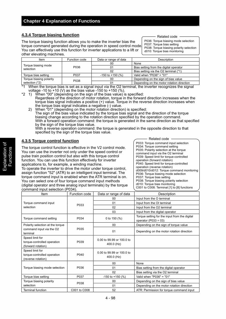
Chapter 4 Explanation of Functions
4 - 98
Exp
lana
tion
of
Func
tions
4.3.4 Torque biasing function The torque biasing function allows you to make the inverter bias the torque command generated during the operation in speed control mode. You can effectively use this function for inverter applications to a lift or other elevating machines.
Item Function code Data or range of data Description 00 None 01 Bias setting from the digital operator Torque biasing mode
selection P036 02 Bias setting via the O2 terminal (*1)
Torque bias setting P037 -150 to +150 (%) Valid when "P036" = "01" 00 Depending on the sign of bias value Torque biasing polarity
selection (*2) P038 01 Depending on the motor rotation direction
*1 When the torque bias is set as a signal input via the O2 terminal, the inverter recognizes the signal voltage -10 to +10 (V) as the bias value -150 to +150 (%).
*2 1) When "00" (depending on the sign of the bias value) is specified: Regardless of the direction of motor rotation, torque in the forward direction increases when the
torque bias signal indicates a positive (+) value. Torque in the reverse direction increases when the torque bias signal indicates a negative (-) value.
2) When "01" (depending on the motor rotation direction) is specified: The sign of the bias value indicated by the torque bias signal and the direction of the torque
biasing change according to the rotation direction specified by the operation command. With a forward operation command: the torque is generated in the same direction as that specified
by the sign of the torque bias value. With a reverse operation command: the torque is generated in the opposite direction to that
specified by the sign of the torque bias value. 4.3.5 Torque control function The torque control function is effective in the V2 control mode. You can use the inverter not only under the speed control or pulse train position control but also with this torque control function. You can use this function effectively for inverter applications to, for example, a winding machine. To operate the inverter to drive the motor under torque control, assign function "52" (ATR) to an intelligent input terminal. The torque command input is enabled when the ATR terminal is on. You can select one of four torque command input methods (digital operator and three analog input terminals) by the torque command input selection (P034).
Item Function code Data or range of data Description 00 Input from the O terminal 01 Input from the OI terminal 02 Input from the O2 terminal
Torque command input selection
P033
03 Input from the digital operator
Torque command setting P034 0 to 150 (%) Torque setting for the input from the digital operator (P033 = 03)
00 Depending on the sign of torque value Polarity selection at the torque command input via the O2 terminal
P035 01 Depending on the motor rotation direction
Speed limit for torque-controlled operation (forward rotation)
P039 0.00 to 99.99 or 100.0 to
400.0 (Hz)
Speed limit for torque-controlled operation (reverse rotation)
P040 0.00 to 99.99 or 100.0 to
400.0 (Hz)
00 None 01 Bias setting from the digital operator Torque biasing mode selection P036 02 Bias setting via the O2 terminal
Torque bias setting P037 -150 to +150 (%) Valid when "P036" = "01" 00 Depending on the sign of bias value Torque biasing polarity
selection P038
01 Depending on the motor rotation direction Terminal function C001 to C008 52 ATR: Permission for torque command input
P036: Torque biasing mode selection P037: Torque bias setting P038: Torque biasing polarity selection d010: Torque bias monitoring
Related code
P033: Torque command input selection P034: Torque command setting P035: Polarity selection at the torque command input via the O2 terminal P039: Speed limit for torque-controlled operation (forward rotation) P040: Speed limit for torque-controlled operation (reverse rotation) d009/d010/d012: Torque command monitoring P036: Torque biasing mode selection P037: Torque bias setting P038: Torque biasing polarity selection d010: Torque bias monitoring C001 to C008: Terminal [1] to [8] functions
Related code
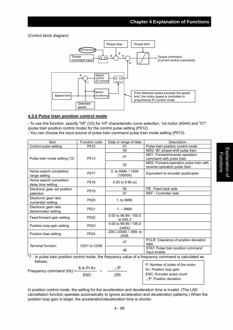
Chapter 4 Explanation of Functions
4 - 99
Explanation of Functions
(Control block diagram) 4.3.6 Pulse train position control mode - To use this function, specify "05" (V2) for V/F characteristic curve selection, 1st motor (A044) and "01" (pulse train position control mode) for the control pulse setting (P012). - You can choose the input source of pulse train command pulse train mode setting (P013).
Item Function code Data or range of data Description Control pulse setting P012 01 Pulse train position control mode
00 MD0: 90°-phase-shift pulse train
01 MD1: Forward/reverse operation command with pulse train Pulse train mode setting (*2) P013
02 MD2: Forward-operation pulse train with reverse-operation pulse train
Home search completion range setting P017 0. to 9999. / 1000
(100000) Equivalent to encoder quadruplex
Home search completion delay time setting P018 0.00 to 9.99 (s)
00 FB : Feed back side Electronic gear set position selection
P019 01 REF : Controller side Electronic gear ratio numerator setting P020 1. to 9999.
Electronic gear ratio denominator setting P021 1. – 9999.
Feed-forward gain setting P022 0.00 to 99.99 / 100.0 to 655.3
Position loop gain setting P023 0.00 to 99.99 / 100.0 (rad/s)
Position bias setting P024 -204 (-2048) / -999. to 2048.
47 PCLR: Clearance of position deviation data Terminal function C001 to C008
48 STAT: Pulse train position command input enable
*1 In pulse train position control mode, the frequency value of a frequency command is calculated as follows:
Frequency command (Hz) = × In position control mode, the setting for the acceleration and deceleration time is invalid. (The LAD cancellation function operates automatically to ignore acceleration and deceleration patterns.) When the position loop gain is larger, the acceleration/deceleration time is shorter.
ATR terminal
Torque command input
Torque bias Torque limit
Torque command (Current control command)
Speed limit
Detected speed
Speed control (P control)
Speed monitoring
If the detected speed exceeds the speed limit, the motor speed is controlled in proportional (P) control mode.
P: Number of poles of the motor Kv: Position loop gain ENC: Encoder pulse count ⊿P: Position deviation
6.4×P×Kv
ENC
⊿P
255
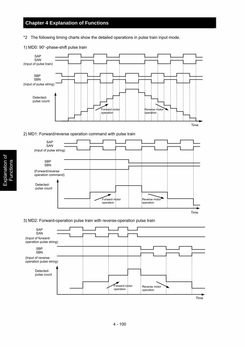
Chapter 4 Explanation of Functions
4 - 100
Exp
lana
tion
of
Func
tions
*2 The following timing charts show the detailed operations in pulse train input mode. 1) MD0: 90°-phase-shift pulse train
SAPSAN
SBPSBN
正転 逆転
(パルス列入力)
検出パルス数
時間
2) MD1: Forward/reverse operation command with pulse train
(パルス列入力)
SAPSAN
SBPSBN
正転 逆転
(正逆転指令)
検出パルス数
時間 3) MD2: Forward-operation pulse train with reverse-operation pulse train
SAPSAN
SBPSBN
正転 逆転
(正転パルス列入力)
(逆転パルス列入力)
検出パルス数
時間
SAP SAN
SBP SBN
Forward motor operation
Detected- pulse count
Reverse motor operation
Time
SAP SAN
SBP SBN
Detected- pulse count
(Forward/reverse operation command)
Forward motor operation
Reverse motor operation
Time
(Input of pulse string)
Forward motor operation
Reverse motor operation
Time
(Input of reverse- operation pulse string)
SAP SAN
SBP SBN
Detected- pulse count
(Input of forward- operation pulse string)
(Input of pulse train)
(Input of pulse string)
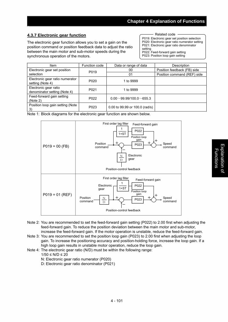
Chapter 4 Explanation of Functions
4 - 101
Explanation of Functions
4.3.7 Electronic gear function The electronic gear function allows you to set a gain on the position command or position feedback data to adjust the ratio between the main motor and sub-motor speeds during the synchronous operation of the motors.
Item Function code Data or range of data Description 00 Position feedback (FB) side Electronic gear set position
selection P019 01 Position command (REF) side
Electronic gear ratio numerator setting (Note 4) P020 1 to 9999
Electronic gear ratio denominator setting (Note 4) P021 1 to 9999
Feed-forward gain setting (Note 2) P022 0.00~99.99/100.0~655.3
Position loop gain setting (Note 3) P023 0.00 to 99.99 or 100.0 (rad/s)
Note 1: Block diagrams for the electronic gear function are shown below.
P019 = 00 (FB)
P019 = 01 (REF)
Note 2: You are recommended to set the feed-forward gain setting (P022) to 2.00 first when adjusting the
feed-forward gain. To reduce the position deviation between the main motor and sub-motor, increase the feed-forward gain. If the motor operation is unstable, reduce the feed-forward gain.
Note 3: You are recommended to set the position loop gain (P023) to 2.00 first when adjusting the loop gain. To increase the positioning accuracy and position-holding force, increase the loop gain. If a high loop gain results in unstable motor operation, reduce the loop gain.
Note 4: The electronic gear ratio (N/D) must be within the following range: 1/50 ≤ N/D ≤ 20 N: Electronic gear ratio numerator (P020) D: Electronic gear ratio denominator (P021)
P019: Electronic gear set position selection P020: Electronic gear ratio numerator settingP021: Electronic gear ratio denominator setting P022: Feed-forward gain setting P023: Position loop gain setting
Related code
Position-control feedback
D
N
P023
P022
Feed-forward gain
Position loop gain
Position command
Speed command
Electronic gear
1
1+ST
First order lag filter
P023
P022
N
D
Position command
Speed command
Feed-forward gain
Position loop gain
Position-control feedback
Electronic gear
1
1+ST
First order lag filter
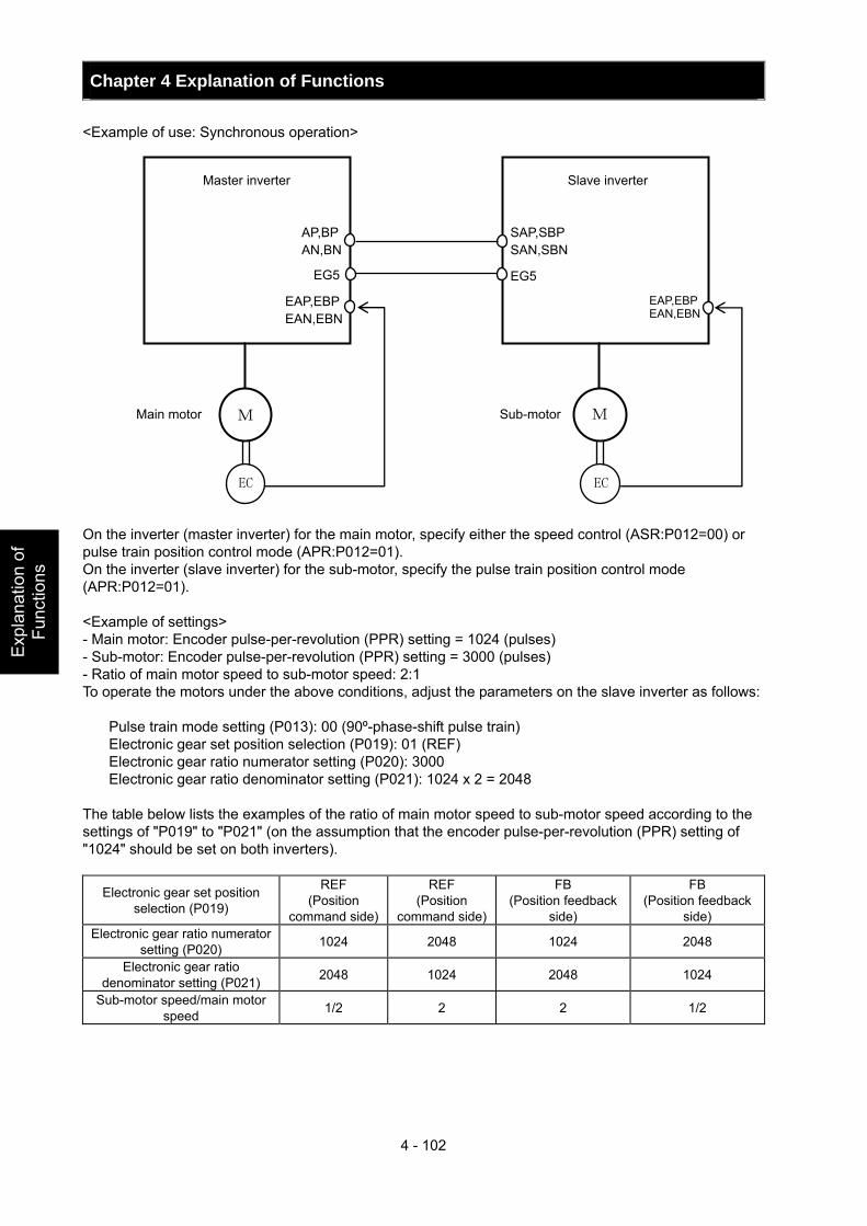
Chapter 4 Explanation of Functions
4 - 102
Exp
lana
tion
of
Func
tions
<Example of use: Synchronous operation> On the inverter (master inverter) for the main motor, specify either the speed control (ASR:P012=00) or pulse train position control mode (APR:P012=01). On the inverter (slave inverter) for the sub-motor, specify the pulse train position control mode (APR:P012=01). <Example of settings> - Main motor: Encoder pulse-per-revolution (PPR) setting = 1024 (pulses) - Sub-motor: Encoder pulse-per-revolution (PPR) setting = 3000 (pulses) - Ratio of main motor speed to sub-motor speed: 2:1 To operate the motors under the above conditions, adjust the parameters on the slave inverter as follows:
Pulse train mode setting (P013): 00 (90º-phase-shift pulse train) Electronic gear set position selection (P019): 01 (REF) Electronic gear ratio numerator setting (P020): 3000 Electronic gear ratio denominator setting (P021): 1024 x 2 = 2048
The table below lists the examples of the ratio of main motor speed to sub-motor speed according to the settings of "P019" to "P021" (on the assumption that the encoder pulse-per-revolution (PPR) setting of "1024" should be set on both inverters).
Electronic gear set position selection (P019)
REF (Position
command side)
REF (Position
command side)
FB (Position feedback
side)
FB (Position feedback
side) Electronic gear ratio numerator
setting (P020) 1024 2048 1024 2048
Electronic gear ratio denominator setting (P021) 2048 1024 2048 1024
Sub-motor speed/main motor speed 1/2 2 2 1/2
AP,BP AN,BN
M
EC
M
EC
EG5
EAP,EBP EAN,EBN
SAP,SBP SAN,SBN EG5
EAP,EBP EAN,EBN
Master inverter Slave inverter
Main motor Sub-motor
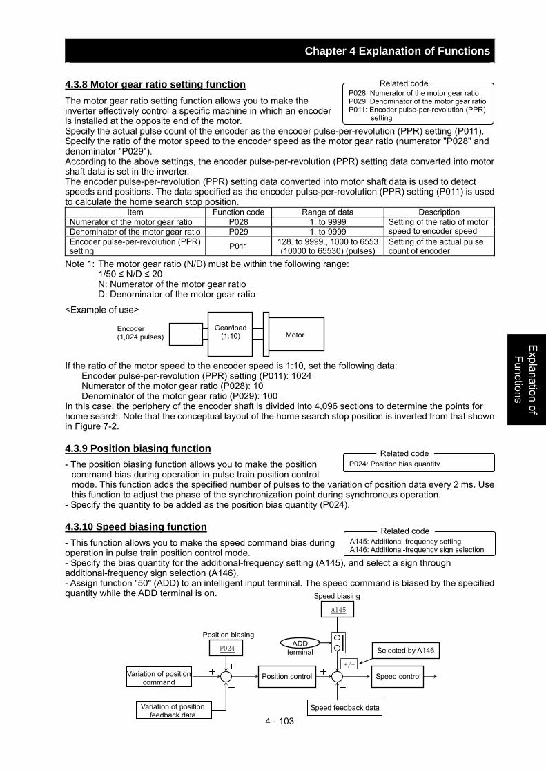
Chapter 4 Explanation of Functions
4 - 103
Explanation of Functions
4.3.8 Motor gear ratio setting function The motor gear ratio setting function allows you to make the inverter effectively control a specific machine in which an encoder is installed at the opposite end of the motor. Specify the actual pulse count of the encoder as the encoder pulse-per-revolution (PPR) setting (P011). Specify the ratio of the motor speed to the encoder speed as the motor gear ratio (numerator "P028" and denominator "P029"). According to the above settings, the encoder pulse-per-revolution (PPR) setting data converted into motor shaft data is set in the inverter. The encoder pulse-per-revolution (PPR) setting data converted into motor shaft data is used to detect speeds and positions. The data specified as the encoder pulse-per-revolution (PPR) setting (P011) is used to calculate the home search stop position.
Item Function code Range of data Description Numerator of the motor gear ratio P028 1. to 9999 Denominator of the motor gear ratio P029 1. to 9999
Setting of the ratio of motor speed to encoder speed
Encoder pulse-per-revolution (PPR) setting P011 128. to 9999., 1000 to 6553
(10000 to 65530) (pulses) Setting of the actual pulse count of encoder
Note 1: The motor gear ratio (N/D) must be within the following range: 1/50 ≤ N/D ≤ 20 N: Numerator of the motor gear ratio D: Denominator of the motor gear ratio
<Example of use>
If the ratio of the motor speed to the encoder speed is 1:10, set the following data: Encoder pulse-per-revolution (PPR) setting (P011): 1024 Numerator of the motor gear ratio (P028): 10 Denominator of the motor gear ratio (P029): 100
In this case, the periphery of the encoder shaft is divided into 4,096 sections to determine the points for home search. Note that the conceptual layout of the home search stop position is inverted from that shown in Figure 7-2. 4.3.9 Position biasing function - The position biasing function allows you to make the position
command bias during operation in pulse train position control mode. This function adds the specified number of pulses to the variation of position data every 2 ms. Use this function to adjust the phase of the synchronization point during synchronous operation.
- Specify the quantity to be added as the position bias quantity (P024). 4.3.10 Speed biasing function - This function allows you to make the speed command bias during operation in pulse train position control mode. - Specify the bias quantity for the additional-frequency setting (A145), and select a sign through additional-frequency sign selection (A146). - Assign function "50" (ADD) to an intelligent input terminal. The speed command is biased by the specified quantity while the ADD terminal is on.
P028: Numerator of the motor gear ratio P029: Denominator of the motor gear ratio P011: Encoder pulse-per-revolution (PPR)
setting
Related code
Encoder (1,024 pulses)
Gear/load (1:10) Motor
P024: Position bias quantity Related code
A145: Additional-frequency setting A146: Additional-frequency sign selection
Related code
Variation of position command
Variation of position feedback data
P024
Position control
Speed feedback data
Speed control +/-
Selected by A146 ADD
terminal
Position biasing
A145
Speed biasing
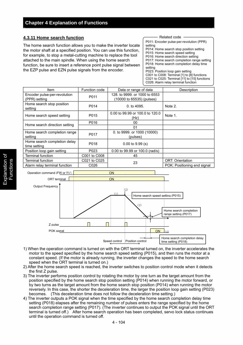
Chapter 4 Explanation of Functions
4 - 104
Exp
lana
tion
of
Func
tions
4.3.11 Home search function The home search function allows you to make the inverter locate the motor shaft at a specified position. You can use this function, for example, to stop a metal-cutting machine to replace the tool attached to the main spindle. When using the home search function, be sure to insert a reference point pulse signal between the EZP pulse and EZN pulse signals from the encoder.
Item Function code Data or range of data Description Encoder pulse-per-revolution (PPR) setting P011 128. to 9999. or 1000 to 6553
(10000 to 65535) (pulses)
Home search stop position setting P014 0. to 4095. Note 2.
Home search speed setting P015 0.00 to 99.99 or 100.0 to 120.0 (Hz) Note 1.
P016 00 Home search direction setting 01
Home search completion range setting P017 0. to 9999. or 1000 (10000)
(pulses)
Home search completion delay time setting P018 0.00 to 9.99 (s)
Position loop gain setting P023 0.00 to 99.99 or 100.0 (rad/s) Terminal function C001 to C008 45 Terminal function C021 to C025 ORT: Orientation Alarm relay terminal function C026
23 POK: Positioning end signal
1) When the operation command is turned on with the ORT terminal turned on, the inverter accelerates the
motor to the speed specified by the home search speed setting (P015), and then runs the motor at a constant speed. (If the motor is already running, the inverter changes the speed to the home search speed when the ORT terminal is turned on.)
2) After the home search speed is reached, the inverter switches to position control mode when it detects the first Z pulse.
3) The inverter performs position control by rotating the motor by one turn as the target amount from the position specified by the home search stop position setting (P014) when running the motor forward, or by two turns as the target amount from the home search stop position (P014) when running the motor reversely. In this case, the shorter the deceleration time, the larger the position loop gain setting (P023) becomes. (This deceleration time does not follow the deceleration time setting.)
4) The inverter outputs a POK signal when the time specified by the home search completion delay time setting (P018) elapses after the remaining number of pulses enters the range specified by the home search completion range setting (P017). (The inverter continues to output the POK signal until the ORT terminal is turned off.) After home search operation has been completed, servo lock status continues until the operation command is turned off.
P011: Encoder pulse-per-revolution (PPR) setting P014: Home search stop position setting P015: Home search speed setting P016: Home search direction setting P017: Home search completion range setting P018: Home search completion delay time setting P023: Position loop gain setting C001 to C008: Terminal [1] to [8] functions C021 to C025: Terminal [11] to [15] functions C026: Alarm relay terminal function
Related code
Operation command (FW or RV)
ORT terminal
Z pulse
Output Frequency
Home search speed setting (P015)
ON
ON
ONPOK signal
Home search completion range setting (P017)
Home search completion delay time setting (P018) Speed control Position control
(1)
(2)
(3)
(4)
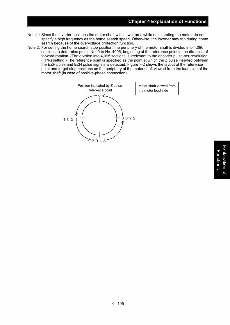
Chapter 4 Explanation of Functions
4 - 105
Explanation of Functions
Note 1: Since the inverter positions the motor shaft within two turns while decelerating the motor, do not specify a high frequency as the home search speed. Otherwise, the inverter may trip during home search because of the overvoltage protection function.
Note 2: For setting the home search stop position, the periphery of the motor shaft is divided into 4,096 sections to determine points No. 0 to No. 4095, beginning at the reference point in the direction of forward rotation. (The division into 4,095 sections is irrelevant to the encoder pulse-per-revolution (PPR) setting.) The reference point is specified as the point at which the Z pulse inserted between the EZP pulse and EZN pulse signals is detected. Figure 7-2 shows the layout of the reference point and target stop positions on the periphery of the motor shaft viewed from the load side of the motor shaft (in case of positive-phase connection).
1024 3072
2048
Motor shaft viewed from the motor load side
Position indicated by Z pulse Reference point
0
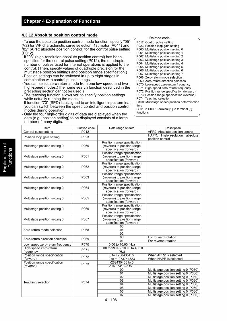
Chapter 4 Explanation of Functions
4 - 106
Exp
lana
tion
of
Func
tions
4.3.12 Absolute position control mode - To use the absolute position control mode function, specify "05" (V2) for V/F characteristic curve selection, 1st motor (A044) and "02" (APR: absolute position control) for the control pulse setting (P012). - If "03" (high-resolution absolute position control) has been
specified for the control pulse setting (P012), the quadruple number of pulses used for internal operations is applied to the control. (Then, specify values of quadruple precision for the multistage position settings and position range specification.)
- Position settings can be switched in up to eight stages in combination with control pulse settings.
- You can select zero-return mode from one low-speed and two high-speed modes.(The home search function described in the preceding section cannot be used.)
- The teaching function allows you to specify position settings while actually running the machine.
- If function "73" (SPD) is assigned to an intelligent input terminal, you can switch between the speed control and position control modes during operation.
- Only the four high-order digits of data are displayed when the data (e.g., position setting) to be displayed consists of a large number of many digits.
Item Function code Data/range of data Description Control pulse setting P012 APR2: Absolute position control Position loop gain setting P023 HAPR: High-resolution absolute
position control
Multistage position setting 0 P060 Position range specification (reverse) to position range
specification (forward)
Multistage position setting 0 P061 Position range specification (reverse) to position range
specification (forward)
Multistage position setting 0 P062 Position range specification (reverse) to position range
specification (forward)
Multistage position setting 0 P063 Position range specification (reverse) to position range
specification (forward)
Multistage position setting 0 P064 Position range specification (reverse) to position range
specification (forward)
Multistage position setting 0 P065 Position range specification (reverse) to position range
specification (forward)
Multistage position setting 0 P066 Position range specification (reverse) to position range
specification (forward)
Multistage position setting 0 P067 Position range specification (reverse) to position range
specification (forward)
00 01 Zero-return mode selection P068 02 00 For forward rotation Zero-return direction selection P069 01 For reverse rotation
Low-speed zero-return frequency P070 0.00 to 10.00 (Hz) High-speed zero-return frequency P071 0.00 to 99.99 / 100.0 to 400.0
(Hz) 0 to +268435455 When APR2 is selected Position range specification
(forward) P072 0 to +1073741823 When HAPR is selected -268435455 to 0 Position range specification
(reverse) P073 -1073741823 to 0 00 Multistage position setting 0 (P060)01 Multistage position setting 0 (P060)02 Multistage position setting 0 (P060)03 Multistage position setting 0 (P060)04 Multistage position setting 0 (P060)05 Multistage position setting 0 (P060)06 Multistage position setting 0 (P060)
Teaching selection P074
07 Multistage position setting 0 (P060)
P012: Control pulse setting P023: Position loop gain setting P060: Multistage position setting 0 P061: Multistage position setting 1 P062: Multistage position setting 2 P063: Multistage position setting 3 P064: Multistage position setting 4 P065: Multistage position setting 5 P066: Multistage position setting 6 P067: Multistage position setting 7 P068: Zero-return mode selection P069: Zero-return direction selection P070: Low-speed zero-return frequency P071: High-speed zero-return frequency P072: Position range specification (forward) P073: Position range specification (reverse) P074: Teaching selection C169: Multistage speed/position determination time C001 to C008: Terminal [1] to terminal [8] functions
Related code
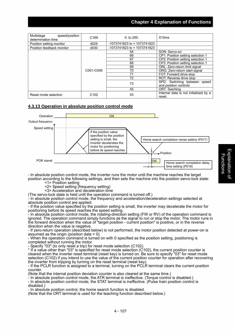
Chapter 4 Explanation of Functions
4 - 107
Explanation of Functions
Multistage speed/position determination time C169 0. to 200. X10ms
Position setting monitor d029 -1073741823 to + 1073741823 Position feedback monitor d030 -1073741823 to + 1073741823
54 SON: Servo-on 66 CP1: Position setting selection 1 67 CP2: Position setting selection 1 68 CP3: Position setting selection 1 69 ORL: Zero-return limit signal 70 ORG: Zero-return start signal 71 FOT: Forward drive stop 72 ROT: Reverse drive stop 73 SPD: Switching between speed
and position controls
C001-C008
45 ORT: Teaching
Reset mode selection C102 03 Internal data is not initialized by a reset.
4.3.13 Operation in absolute position control mode - In absolute position control mode, the inverter runs the motor until the machine reaches the target position according to the following settings, and then sets the machine into the position servo-lock state:
<1> Position setting <2> Speed setting (frequency setting) <3> Acceleration and deceleration time
(The servo-lock state is held until the operation command is turned off.) - In absolute position control mode, the frequency and acceleration/deceleration settings selected at absolute position control are applied. - If the position value specified by the position setting is small, the inverter may decelerate the motor for positioning before its speed reaches the speed setting. - In absolute position control mode, the rotating-direction setting (FW or RV) of the operation command is ignored. The operation command simply functions as the signal to run or stop the motor. The motor runs in the forward direction when the value of "target position - current position" is positive, or in the reverse direction when the value is negative. - If zero-return operation (described below) is not performed, the motor position detected at power-on is assumed as the origin (position data = 0). - When the operation command is turned on with 0 specified as the position setting, positioning is completed without running the motor. - Specify "03" (to only reset a trip) for reset mode selection (C102). * If a value other than "03" is specified for reset mode selection (C102), the current position counter is cleared when the inverter reset terminal (reset key) is turned on. Be sure to specify "03" for reset mode selection (C102) if you intend to use the value of the current position counter for operation after recovering the inverter from tripping by turning on the reset terminal (reset key). - If the PCLR function is assigned to a terminal, turning on the PCLR terminal clears the current position counter. (Note that the internal position deviation counter is also cleared at the same time.) - In absolute position control mode, the ATR terminal is ineffective. (Torque control is disabled.) - In absolute position control mode, the STAT terminal is ineffective. (Pulse train position control is disabled.) - In absolute position control, the home search function is disabled. (Note that the ORT terminal is used for the teaching function described below.)
ON
Output frequency
Position
Speed setting
Operation ON
Home search completion range setting (P017)
Home search completion delay time setting (P018)
POK signal
If the position value specified by the position setting is small, the inverter decelerates the motor for positioning before its speed reaches
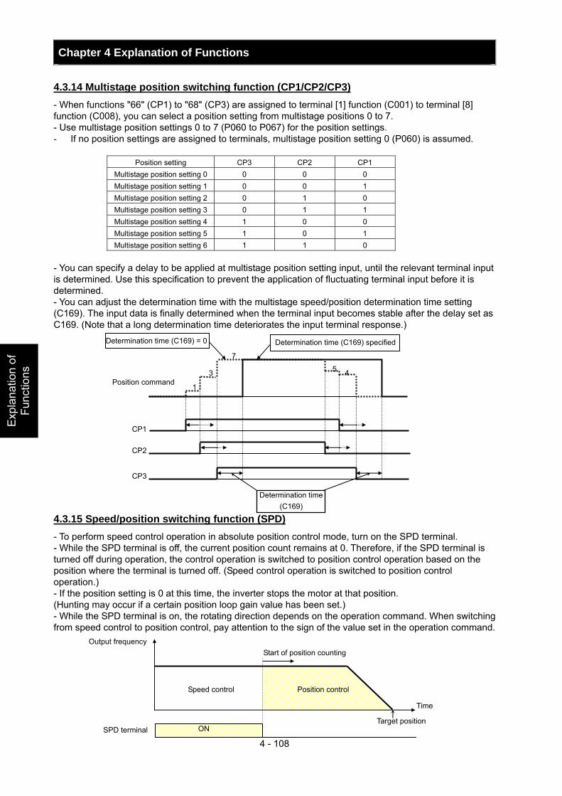
Chapter 4 Explanation of Functions
4 - 108
Exp
lana
tion
of
Func
tions
4.3.14 Multistage position switching function (CP1/CP2/CP3) - When functions "66" (CP1) to "68" (CP3) are assigned to terminal [1] function (C001) to terminal [8] function (C008), you can select a position setting from multistage positions 0 to 7. - Use multistage position settings 0 to 7 (P060 to P067) for the position settings. - If no position settings are assigned to terminals, multistage position setting 0 (P060) is assumed.
Position setting CP3 CP2 CP1 Multistage position setting 0 0 0 0 Multistage position setting 1 0 0 1 Multistage position setting 2 0 1 0 Multistage position setting 3 0 1 1 Multistage position setting 4 1 0 0 Multistage position setting 5 1 0 1 Multistage position setting 6 1 1 0
- You can specify a delay to be applied at multistage position setting input, until the relevant terminal input is determined. Use this specification to prevent the application of fluctuating terminal input before it is determined. - You can adjust the determination time with the multistage speed/position determination time setting (C169). The input data is finally determined when the terminal input becomes stable after the delay set as C169. (Note that a long determination time deteriorates the input terminal response.) 4.3.15 Speed/position switching function (SPD) - To perform speed control operation in absolute position control mode, turn on the SPD terminal. - While the SPD terminal is off, the current position count remains at 0. Therefore, if the SPD terminal is turned off during operation, the control operation is switched to position control operation based on the position where the terminal is turned off. (Speed control operation is switched to position control operation.) - If the position setting is 0 at this time, the inverter stops the motor at that position. (Hunting may occur if a certain position loop gain value has been set.) - While the SPD terminal is on, the rotating direction depends on the operation command. When switching from speed control to position control, pay attention to the sign of the value set in the operation command.
Determination time (C169)
CP1
CP2
CP3
Position command
Determination time (C169) specified
4
1
5 3
Determination time (C169) = 0
7
Position control Speed control
ON
Output frequency
SPD terminal
Time
Target position
Start of position counting
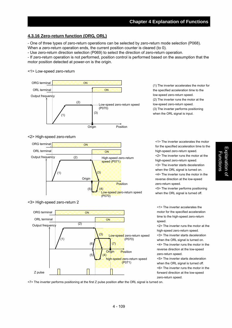
Chapter 4 Explanation of Functions
4 - 109
Explanation of Functions
4.3.16 Zero-return function (ORG, ORL) - One of three types of zero-return operations can be selected by zero-return mode selection (P068). When a zero-return operation ends, the current position counter is cleared (to 0). - Use zero-return direction selection (P069) to select the direction of zero-return operation. - If zero-return operation is not performed, position control is performed based on the assumption that the motor position detected at power-on is the origin. <1> Low-speed zero-return
(1) The inverter accelerates the motor for the specified acceleration time to the low-speed zero-return speed. (2) The inverter runs the motor at the low-speed zero-return speed. (3) The inverter performs positioning when the ORL signal is input.
<2> High-speed zero-return <1> The inverter accelerates the motor for the specified acceleration time to the high-speed zero-return speed. <2> The inverter runs the motor at the high-speed zero-return speed. <3> The inverter starts deceleration when the ORL signal is turned on. <4> The inverter runs the motor in the reverse direction at the low-speed zero-return speed. <5> The inverter performs positioning when the ORL signal is turned off.
<3> High-speed zero-return 2 <1> The inverter accelerates the motor for the specified acceleration time to the high-speed zero-return speed. <2> The inverter runs the motor at the high-speed zero-return speed. <3> The inverter starts deceleration when the ORL signal is turned on. <4> The inverter runs the motor in the reverse direction at the low-speed zero-return speed. <5> The inverter starts deceleration when the ORL signal is turned off. <6> The inverter runs the motor in the forward direction at the low-speed zero-return speed.
<7> The inverter performs positioning at the first Z pulse position after the ORL signal is turned on.
ORG terminal
ORL terminal
ON
ON
(1)
(2)
(3)
Low-speed zero-return speed (P070)
Output frequency
Position Origin
(1)
(2)
(3)
(4) (5)
High-speed zero-return speed (P071)
OORG terminal
ORL terminal
ON
ON
Low-speed zero-return speed (P070)
Output frequency
Position
Origin
(1)
(2)
(3)
(4) (5)
(6) (7)
ORG terminal
ORL terminal
ON
ON
Low-speed zero-return speed (P070)
Output frequency
Position Origin
high-speed zero-return speed (P071)
Z pulse

Chapter 4 Explanation of Functions
4 - 110
Exp
lana
tion
of
Func
tions
4.3.17 Forward/reverse drive stop function (FOT/ROT) - The forward/reverse drive stop function allows you to prevent motor operation from deviating from the specified control range according to signals from the control range limit switches. - When the FOT terminal is turned on, the torque for forward rotation is limited to 10%. When the ROT terminal is turned on, the torque for reverse rotation is limited to 10%. This function can be used as a limit switch function at the machine end. This function is activated by setting 71 (FOT) and 72 (ROT) on intelligent input terminals 1-8 (C001- C008 4.3.18 Position range specification function - The position control ranges for forward and reverse rotations can be specified by the position range specification (forward) (P072) and position range specification (reverse) (P073), respectively. If the value of the current position counter exceeds one of these ranges, a position control range error (E63.* or E73.*) causes the inverter to trip and enter free-running status. - The values specified by P072 and P073 limit the maximum values of multistage position settings 0 to 7 (P060 to P067). (Position settings cannot exceed the specified position ranges.) 4.3.19 Teaching function - The teaching function allows you to make the inverter run and stop the motor arbitrarily, and then store position data as a position command in an arbitrary position command area of memory. - Assign function "45" (ORT) to an intelligent input terminal 1-8 (C001-C008). The ORT terminal functions as the teaching terminal when "02" (absolute position control) or "03" (high-resolution absolute position control) is specified for the control pulse setting (P012). <Teaching procedure> <1> Select the position command to be set by teaching selection (P074). <2> Move the workpiece. - Enter an operation command with the ORT terminal turned on. The speed and acceleration/deceleration settings selected at operation command input are applied. * Teaching operation can be performed when power is input to the power supply terminals (R0 and T0) of the inverter control circuit. The current position counter also operates when an external device moves the workpiece. Therefore, teaching operation can also be performed when the inverter does not operate the machine. Note: In the case above, make sure that the power supply to the power terminals (R, S, and T) of the inverter power circuit or inverter output (U, V, and W) is disconnected from the motor. Performing teaching operation with the power supply and inverter output connected may result in personal injury or damage to equipment. <3> Press the STR key on the digital operator when the target position is reached. (Be sure to press when data is displayed (in case remote operator SRW-OJ, SRW-OEX is used, cursor is on the data value and PRG LED is on) <4> The current position data is set in the memory area corresponding to the position command specified by the teaching selection (P074). (P074 itself is not stored. After power off or reset, 00 (X00) is set.)
Setting of P074 Position command to be set 00 P060: Multistage position setting 001 P061: Multistage position setting 102 P062: Multistage position setting 203 P063: Multistage position setting 304 P064: Multistage position setting 405 P065: Multistage position setting 506 P066: Multistage position setting 607 P067: Multistage position setting 7
ORT terminal
Operation command
Output frequency
Position
ON
ON
The speed setting selected at operation command input is applied.
C001-C008 intelligent input terminals Related code
P072: Position range specification (forward) P073: Position range specification (reverse)
Related code
C001-C008 intelligent input terminals P012: Control pulse setting P013: Home search stop position setting
Related code
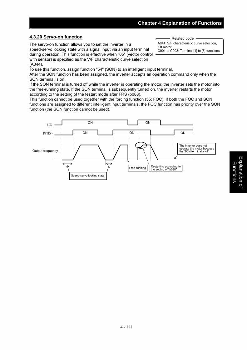
Chapter 4 Explanation of Functions
4 - 111
Explanation of Functions
4.3.20 Servo-on function The servo-on function allows you to set the inverter in a speed-servo locking state with a signal input via an input terminal during operation. This function is effective when "05" (vector control with sensor) is specified as the V/F characteristic curve selection (A044). To use this function, assign function "54" (SON) to an intelligent input terminal. After the SON function has been assigned, the inverter accepts an operation command only when the SON terminal is on. If the SON terminal is turned off while the inverter is operating the motor, the inverter sets the motor into the free-running state. If the SON terminal is subsequently turned on, the inverter restarts the motor according to the setting of the festart mode after FRS (b088). This function cannot be used together with the forcing function (55: FOC). If both the FOC and SON functions are assigned to different intelligent input terminals, the FOC function has priority over the SON function (the SON function cannot be used).
A044: V/F characteristic curve selection, 1st motor C001 to C008: Terminal [1] to [8] functions
Related code
Restarting according to the setting of "b088"
The inverter does not operate the motor because the SON terminal is off.
SON
FW(RV)
Output frequency
Speed-servo locking state
Free-running
ON ON
ON ON ON
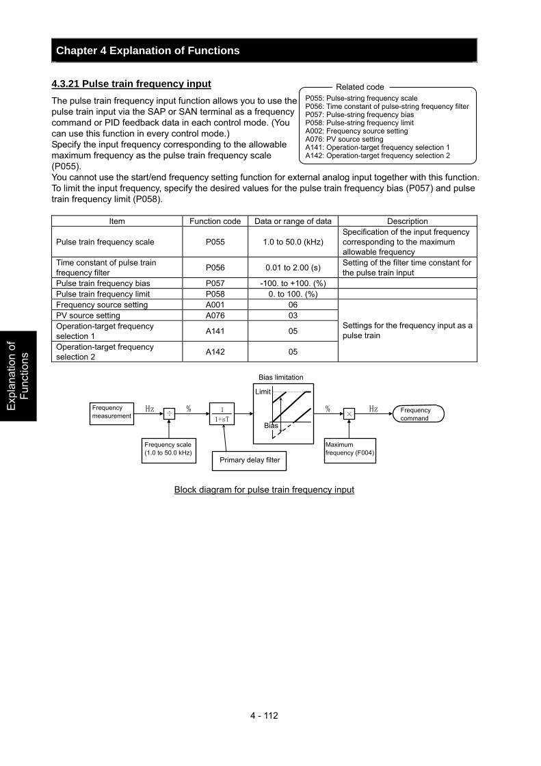
Chapter 4 Explanation of Functions
4 - 112
Exp
lana
tion
of
Func
tions
4.3.21 Pulse train frequency input The pulse train frequency input function allows you to use the pulse train input via the SAP or SAN terminal as a frequency command or PID feedback data in each control mode. (You can use this function in every control mode.) Specify the input frequency corresponding to the allowable maximum frequency as the pulse train frequency scale (P055). You cannot use the start/end frequency setting function for external analog input together with this function. To limit the input frequency, specify the desired values for the pulse train frequency bias (P057) and pulse train frequency limit (P058).
Item Function code Data or range of data Description
Pulse train frequency scale P055 1.0 to 50.0 (kHz) Specification of the input frequency corresponding to the maximum allowable frequency
Time constant of pulse train frequency filter P056 0.01 to 2.00 (s) Setting of the filter time constant for
the pulse train input Pulse train frequency bias P057 -100. to +100. (%) Pulse train frequency limit P058 0. to 100. (%) Frequency source setting A001 06 PV source setting A076 03 Operation-target frequency selection 1 A141 05
Operation-target frequency selection 2 A142 05
Settings for the frequency input as a pulse train
Block diagram for pulse train frequency input
P055: Pulse-string frequency scale P056: Time constant of pulse-string frequency filter P057: Pulse-string frequency bias P058: Pulse-string frequency limit A002: Frequency source setting A076: PV source setting A141: Operation-target frequency selection 1 A142: Operation-target frequency selection 2
Related code
Frequency measurement
Frequency scale (1.0 to 50.0 kHz)
Primary delay filter
Maximum frequency (F004)
Bias limitation
Limit
Bias
Frequency command
÷
1+sT
1 ×
Hz % % Hz
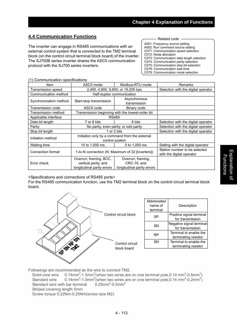
Chapter 4 Explanation of Functions
4 - 113
Explanation of Functions
4.4 Communication Functions
The inverter can engage in RS485 communications with an external control system that is connected to the TM2 terminal block (on the control circuit terminal block board) of the inverter. The SJ700B series inverter shares the ASCII communication protocol with the SJ700 series inverters. (1) Communication specifications
Item ASCII mode Modbus-RTU mode Remarks Transmission speed 2,400, 4,800, 9,600, or 19,200 bps Selection with the digital operatorCommunication method Half-duplex communication
Synchronization method Start-stop transmission Asynchronous transmission
Transmission code ASCII code Binary code Transmission method Transmission beginning with the lowest-order bit Applicable interface RS485 Data bit length 7 or 8 bits 8 bits Selection with the digital operatorParity No parity, even parity, or odd parity Selection with the digital operatorStop bit length 1 or 2 bits Selection with the digital operator
Initiation method Initiation only by a command from the external control system
Waiting time 10 to 1,000 ms 0 to 1,000 ms Setting with the digital operator
Connection format 1-to-N connection (N: Maximum of 32 [inverters]) Station number to be selected with the digital operator
Error check Overrun, framing, BCC,
vertical parity, and longitudinal parity errors
Overrun, framing, CRC-16, and
longitudinal parity errors
<Specifications and connections of RS485 ports> For the RS485 communication function, use the TM2 terminal block on the control circuit terminal block board.
Abbreviated name of terminal
Description
SP Positive signal terminal for transmission
SN Negative signal terminal for transmission
RP Terminal to enable the terminating resistor
SN Terminal to enable the terminating resistor
Followings are recommended as the wire to connect TM2. Solid-core wire 0.14mm2-1.5mm2(when two wires are on one terminal pole,0.14 mm2-0.5mm2) Standard wire 0.14mm2-1.0mm2(when two wires are on one terminal pole,0.14 mm2-0.2mm2) Standard wire with bar terminal 0.25mm2-0.5mm2 Striped covering length 5mm Screw torque 0.22Nm-0.25Nm(screw size M2)
A001: Frequency source setting A002: Run command source setting C071: Communication speed selection C072: Node allocation C073: Communication data length selection C074: Communication parity selection C075: Communication stop bit selection C078: Communication wait time C079: Communication mode selection
Related code
Control circuit block
Control circuit block board
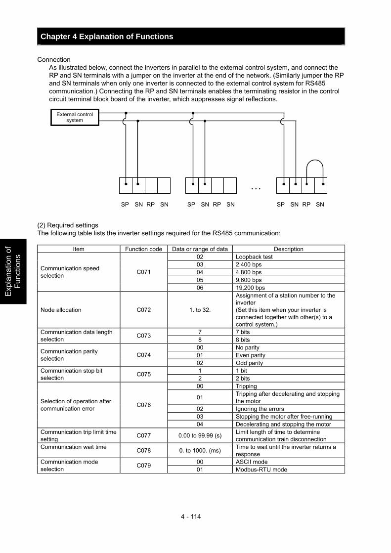
Chapter 4 Explanation of Functions
4 - 114
Exp
lana
tion
of
Func
tions
Connection As illustrated below, connect the inverters in parallel to the external control system, and connect the RP and SN terminals with a jumper on the inverter at the end of the network. (Similarly jumper the RP and SN terminals when only one inverter is connected to the external control system for RS485 communication.) Connecting the RP and SN terminals enables the terminating resistor in the control circuit terminal block board of the inverter, which suppresses signal reflections.
(2) Required settings The following table lists the inverter settings required for the RS485 communication:
Item Function code Data or range of data Description 02 Loopback test 03 2,400 bps 04 4,800 bps 05 9,600 bps
Communication speed selection C071
06 19,200 bps
Node allocation C072 1. to 32.
Assignment of a station number to the inverter (Set this item when your inverter is connected together with other(s) to a control system.)
7 7 bits Communication data length selection C073
8 8 bits 00 No parity 01 Even parity Communication parity
selection C074 02 Odd parity 1 1 bit Communication stop bit
selection C075 2 2 bits
00 Tripping
01 Tripping after decelerating and stopping the motor
02 Ignoring the errors 03 Stopping the motor after free-running
Selection of operation after communication error C076
04 Decelerating and stopping the motor Communication trip limit time setting C077 0.00 to 99.99 (s) Limit length of time to determine
communication train disconnection Communication wait time C078 0. to 1000. (ms) Time to wait until the inverter returns a
response 00 ASCII mode Communication mode
selection C079 01 Modbus-RTU mode
…SP SN RP SN
External control system
SP SN RP SN SP SN RP SN
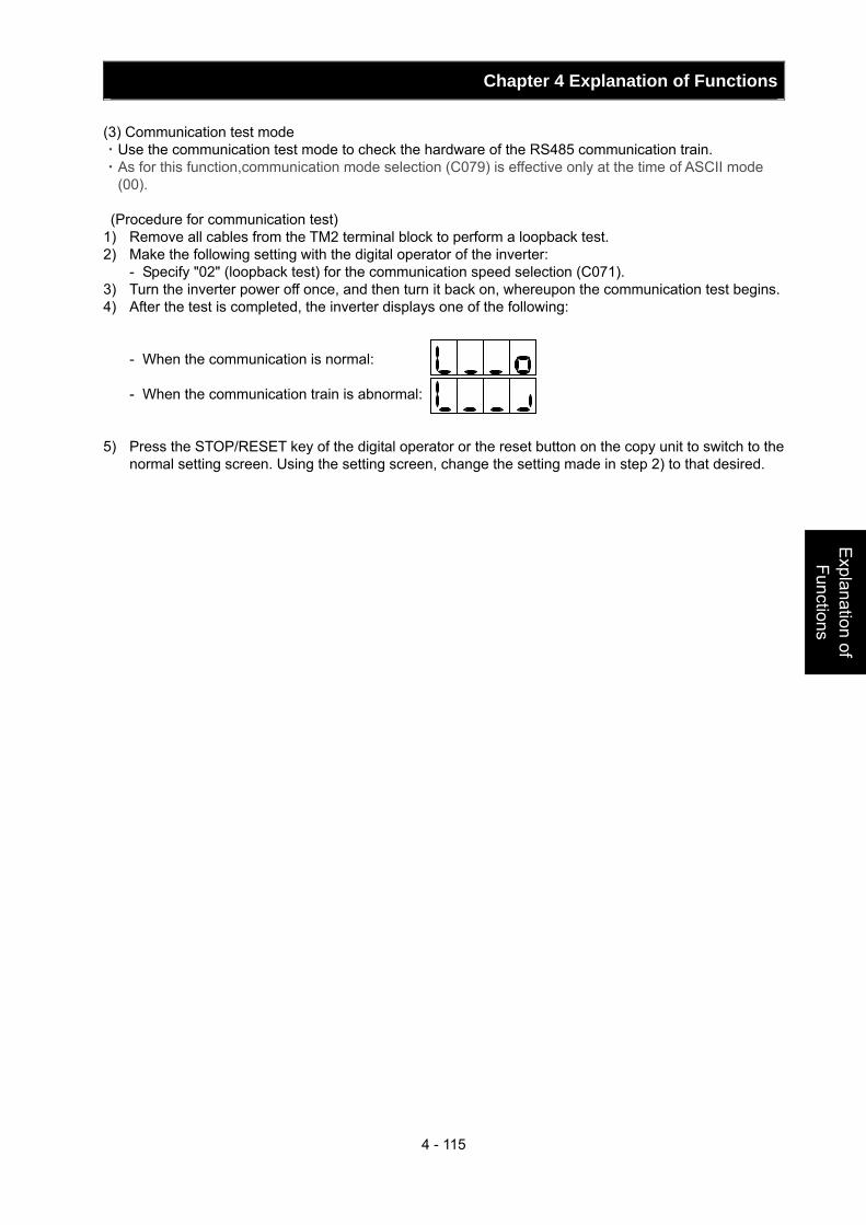
Chapter 4 Explanation of Functions
4 - 115
Explanation of Functions
(3) Communication test mode ・Use the communication test mode to check the hardware of the RS485 communication train. ・As for this function,communication mode selection (C079) is effective only at the time of ASCII mode
(00). (Procedure for communication test) 1) Remove all cables from the TM2 terminal block to perform a loopback test. 2) Make the following setting with the digital operator of the inverter:
- Specify "02" (loopback test) for the communication speed selection (C071). 3) Turn the inverter power off once, and then turn it back on, whereupon the communication test begins. 4) After the test is completed, the inverter displays one of the following:
- When the communication is normal: - When the communication train is abnormal:
5) Press the STOP/RESET key of the digital operator or the reset button on the copy unit to switch to the
normal setting screen. Using the setting screen, change the setting made in step 2) to that desired.
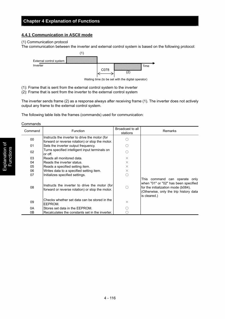
Chapter 4 Explanation of Functions
4 - 116
Exp
lana
tion
of
Func
tions
4.4.1 Communication in ASCII mode (1) Communication protocol The communication between the inverter and external control system is based on the following protocol: (1): Frame that is sent from the external control system to the inverter (2): Frame that is sent from the inverter to the external control system The inverter sends frame (2) as a response always after receiving frame (1). The inverter does not actively output any frame to the external control system. The following table lists the frames (commands) used for communication: Commands
Command Function Broadcast to all stations Remarks
00 Instructs the inverter to drive the motor (for forward or reverse rotation) or stop the motor.
01 Sets the inverter output frequency.
02 Turns specified intelligent input terminals on or off.
03 Reads all monitored data. × 04 Reads the inverter status. × 05 Reads a specified setting item. × 06 Writes data to a specified setting item. × 07 Initializes specified settings.
08 Instructs the inverter to drive the motor (for forward or reverse rotation) or stop the motor.
This command can operate only when "01" or "02" has been specified for the initialization mode (b084). (Otherwise, only the trip history data is cleared.)
09 Checks whether set data can be stored in the EEPROM. ×
0A Stores set data in the EEPROM. 0B Recalculates the constants set in the inverter.
(2)
(1)
C078
External control system Inverter
Waiting time (to be set with the digital operator)
Time
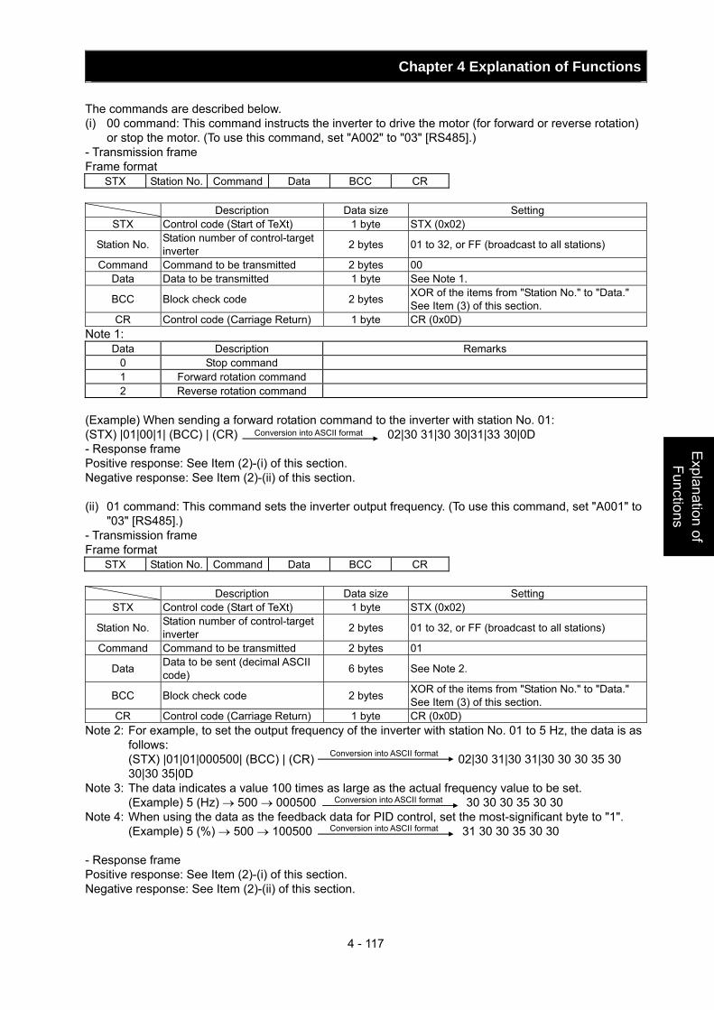
Chapter 4 Explanation of Functions
4 - 117
Explanation of Functions
The commands are described below. (i) 00 command: This command instructs the inverter to drive the motor (for forward or reverse rotation)
or stop the motor. (To use this command, set "A002" to "03" [RS485].) - Transmission frame Frame format
STX Station No. Command Data BCC CR Description Data size Setting
STX Control code (Start of TeXt) 1 byte STX (0x02)
Station No. Station number of control-target inverter 2 bytes 01 to 32, or FF (broadcast to all stations)
Command Command to be transmitted 2 bytes 00 Data Data to be transmitted 1 byte See Note 1.
BCC Block check code 2 bytes XOR of the items from "Station No." to "Data." See Item (3) of this section.
CR Control code (Carriage Return) 1 byte CR (0x0D) Note 1:
Data Description Remarks 0 Stop command 1 Forward rotation command 2 Reverse rotation command
(Example) When sending a forward rotation command to the inverter with station No. 01: (STX) |01|00|1| (BCC) | (CR) 02|30 31|30 30|31|33 30|0D - Response frame Positive response: See Item (2)-(i) of this section. Negative response: See Item (2)-(ii) of this section. (ii) 01 command: This command sets the inverter output frequency. (To use this command, set "A001" to
"03" [RS485].) - Transmission frame Frame format
STX Station No. Command Data BCC CR Description Data size Setting
STX Control code (Start of TeXt) 1 byte STX (0x02)
Station No. Station number of control-target inverter 2 bytes 01 to 32, or FF (broadcast to all stations)
Command Command to be transmitted 2 bytes 01
Data Data to be sent (decimal ASCII code) 6 bytes See Note 2.
BCC Block check code 2 bytes XOR of the items from "Station No." to "Data." See Item (3) of this section.
CR Control code (Carriage Return) 1 byte CR (0x0D) Note 2: For example, to set the output frequency of the inverter with station No. 01 to 5 Hz, the data is as
follows: (STX) |01|01|000500| (BCC) | (CR) 02|30 31|30 31|30 30 30 35 30
30|30 35|0D Note 3: The data indicates a value 100 times as large as the actual frequency value to be set. (Example) 5 (Hz) → 500 → 000500 30 30 30 35 30 30 Note 4: When using the data as the feedback data for PID control, set the most-significant byte to "1".
(Example) 5 (%) → 500 → 100500 31 30 30 35 30 30
- Response frame Positive response: See Item (2)-(i) of this section. Negative response: See Item (2)-(ii) of this section.
Conversion into ASCII format
Conversion into ASCII format
Conversion into ASCII format
Conversion into ASCII format
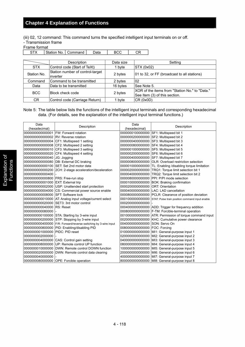
Chapter 4 Explanation of Functions
4 - 118
Exp
lana
tion
of
Func
tions
(iii) 02, 12 command: This command turns the specified intelligent input terminals on or off. - Transmission frame Frame format
STX Station No. Command Data BCC CR Description Data size Setting
STX Control code (Start of TeXt) 1 byte STX (0x02)
Station No. Station number of control-target inverter 2 bytes 01 to 32, or FF (broadcast to all stations)
Command Command to be transmitted 2 bytes 02 Data Data to be transmitted 16 bytes See Note 5.
BCC Block check code 2 bytes XOR of the items from "Station No." to "Data." See Item (3) of this section.
CR Control code (Carriage Return) 1 byte CR (0x0D) Note 5: The table below lists the functions of the intelligent input terminals and corresponding hexadecimal
data. (For details, see the explanation of the intelligent input terminal functions.)
Data (hexadecimal) Description Data
(hexadecimal) Description
0000000000000001 0000000000000002 0000000000000004 0000000000000008 0000000000000010 0000000000000020 0000000000000040 0000000000000080 0000000000000100 0000000000000200 0000000000000400 0000000000000800 0000000000001000 0000000000002000 0000000000004000 0000000000008000 0000000000010000 0000000000020000 0000000000040000 0000000000080000 0000000000100000 0000000000200000 0000000000400000 0000000000800000 0000000001000000 0000000002000000 0000000004000000 0000000008000000 0000000010000000 0000000020000000 0000000040000000 0000000080000000
FW: Forward rotation RV: Reverse rotation CF1: Multispeed 1 setting CF2: Multispeed 2 setting CF3: Multispeed 3 setting CF4: Multispeed 4 setting JG: Jogging DB: External DC braking SET: Set 2nd motor data 2CH: 2-stage acceleration/deceleration - FRS: Free-run stop EXT: External trip USP: Unattended start protection CS: Commercial power source enable SFT: Software lock AT: Analog input voltage/current select SET3: 3rd motor control RS: Reset - STA: Starting by 3-wire input STP: Stopping by 3-wire input F/R: Forward/reverse switching by 3-wire input PID: Enabling/disabling PID PIDC: PID reset - CAS: Control gain setting UP: Remote control UP function DWN: Remote control DOWN function DWN: Remote control data clearing - OPE: Forcible operation
00000001000000000000000200000000000000040000000000000008000000000000001000000000000000200000000000000040000000000000008000000000000001000000000000000200000000000000040000000000000008000000000000001000000000000000200000000000000040000000000000008000000000000001000000000000000200000000000000040000000000000008000000000000001000000000000000200000000000000040000000000000008000000000000001000000000000000200000000000000040000000000000008000000000000001000000000000000200000000000000040000000000000008000000000000000
SF1: Multispeed bit 1 SF2: Multispeed bit 2 SF3: Multispeed bit 3 SF4: Multispeed bit 4 SF5: Multispeed bit 5 SF6: Multispeed bit 6 SF7: Multispeed bit 7 OLR: Overload restriction selection TL: Enabling /disabling torque limitation TRQ1: Torque limit selection bit 1 TRQ2: Torque limit selection bit 2 PPI: P/PI mode selection BOK: Braking confirmation ORT: Orientation LAC: LAD cancellation PCLR: Clearance of position deviation STAT: Pulse train position command input enable - ADD: Trigger for frequency addition F-TM: Forcible-terminal operation ATR: Permission of torque command inputKHC: Cumulative power clearance SON: Servo On FOC: Forcing MI1: General-purpose input 1 MI2: General-purpose input 2 MI3: General-purpose input 3 MI4: General-purpose input 4 MI5: General-purpose input 5 MI6: General-purpose input 6 MI7: General-purpose input 7 MI8: General-purpose input 8
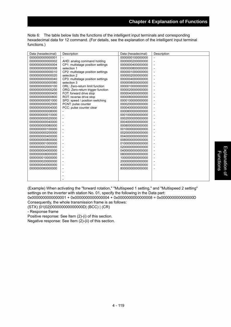
Chapter 4 Explanation of Functions
4 - 119
Explanation of Functions
Note 6: The table below lists the functions of the intelligent input terminals and corresponding hexadecimal data for 12 command. (For details, see the explanation of the intelligent input terminal functions.)
Data (hexadecimal) Description Data (hexadecimal) Description 0000000000000001 0000000000000002 0000000000000004 0000000000000008 0000000000000010 0000000000000020 0000000000000040 0000000000000080 0000000000000100 0000000000000200 0000000000000400 0000000000000800 0000000000001000 0000000000002000 0000000000004000 0000000000008000 0000000000010000 0000000000020000 0000000000040000 0000000000080000 0000000000100000 0000000000200000 0000000000400000 0000000000800000 0000000001000000 0000000002000000 0000000004000000 0000000008000000 0000000010000000 0000000020000000 0000000040000000 0000000080000000
- AHD: analog command holding CP1: multistage position settings selection 1 CP2: multistage position settings selection 2 CP3: multistage position settings selection 3 ORL: Zero-return limit function ORG: Zero-return trigger function FOT: forward drive stop ROT: reverse drive stop SPD: speed / position switching PCNT: pulse counter PCC: pulse counter clear - - - - - - - - - - - - - - - - - - - -
0000000100000000 0000000200000000 0000000400000000 0000000800000000 0000001000000000 0000002000000000 0000004000000000 0000008000000000 0000010000000000 0000020000000000 0000040000000000 0000080000000000 0000100000000000 0000200000000000 0000400000000000 0000800000000000 0001000000000000 0002000000000000 0004000000000000 0008000000000000 0010000000000000 0020000000000000 0040000000000000 0080000000000000 0100000000000000 0200000000000000 0400000000000000 0800000000000000 1000000000000000 2000000000000000 4000000000000000 8000000000000000
- - - - - - - - - - - - - - - - - - - - - - - - - - - - - - - -
(Example) When activating the "forward rotation," "Multispeed 1 setting," and "Multispeed 2 setting" settings on the inverter with station No. 01, specify the following in the Data part: 0x0000000000000001 + 0x0000000000000004 + 0x0000000000000008 = 0x000000000000000D Consequently, the whole transmission frame is as follows: (STX) |01|02|000000000000000D| (BCC) | (CR) - Response frame Positive response: See Item (2)-(i) of this section. Negative response: See Item (2)-(ii) of this section.
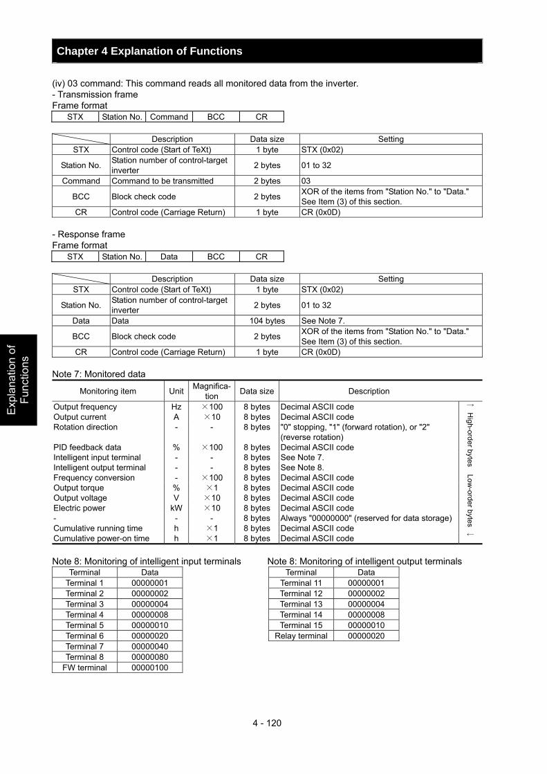
Chapter 4 Explanation of Functions
4 - 120
Exp
lana
tion
of
Func
tions
(iv) 03 command: This command reads all monitored data from the inverter. - Transmission frame Frame format
STX Station No. Command BCC CR Description Data size Setting
STX Control code (Start of TeXt) 1 byte STX (0x02)
Station No. Station number of control-target inverter 2 bytes 01 to 32
Command Command to be transmitted 2 bytes 03
BCC Block check code 2 bytes XOR of the items from "Station No." to "Data." See Item (3) of this section.
CR Control code (Carriage Return) 1 byte CR (0x0D) - Response frame Frame format
STX Station No. Data BCC CR Description Data size Setting
STX Control code (Start of TeXt) 1 byte STX (0x02)
Station No. Station number of control-target inverter 2 bytes 01 to 32
Data Data 104 bytes See Note 7.
BCC Block check code 2 bytes XOR of the items from "Station No." to "Data." See Item (3) of this section.
CR Control code (Carriage Return) 1 byte CR (0x0D) Note 7: Monitored data
Monitoring item Unit Magnifica-tion Data size Description
Output frequency Hz ×100 8 bytes Decimal ASCII code Output current A ×10 8 bytes Decimal ASCII code Rotation direction - - 8 bytes "0" stopping, "1" (forward rotation), or "2"
(reverse rotation) PID feedback data % ×100 8 bytes Decimal ASCII code Intelligent input terminal - - 8 bytes See Note 7. Intelligent output terminal - - 8 bytes See Note 8. Frequency conversion - ×100 8 bytes Decimal ASCII code Output torque % ×1 8 bytes Decimal ASCII code Output voltage V ×10 8 bytes Decimal ASCII code Electric power kW ×10 8 bytes Decimal ASCII code - - - 8 bytes Always "00000000" (reserved for data storage) Cumulative running time h ×1 8 bytes Decimal ASCII code Cumulative power-on time h ×1 8 bytes Decimal ASCII code
↑ H
igh-order bytes Low-order bytes
↓
Note 8: Monitoring of intelligent input terminals Note 8: Monitoring of intelligent output terminals
Terminal Data Terminal Data Terminal 1 00000001 Terminal 11 00000001 Terminal 2 00000002 Terminal 12 00000002 Terminal 3 00000004 Terminal 13 00000004 Terminal 4 00000008 Terminal 14 00000008 Terminal 5 00000010 Terminal 15 00000010 Terminal 6 00000020 Relay terminal 00000020 Terminal 7 00000040 Terminal 8 00000080
FW terminal 00000100
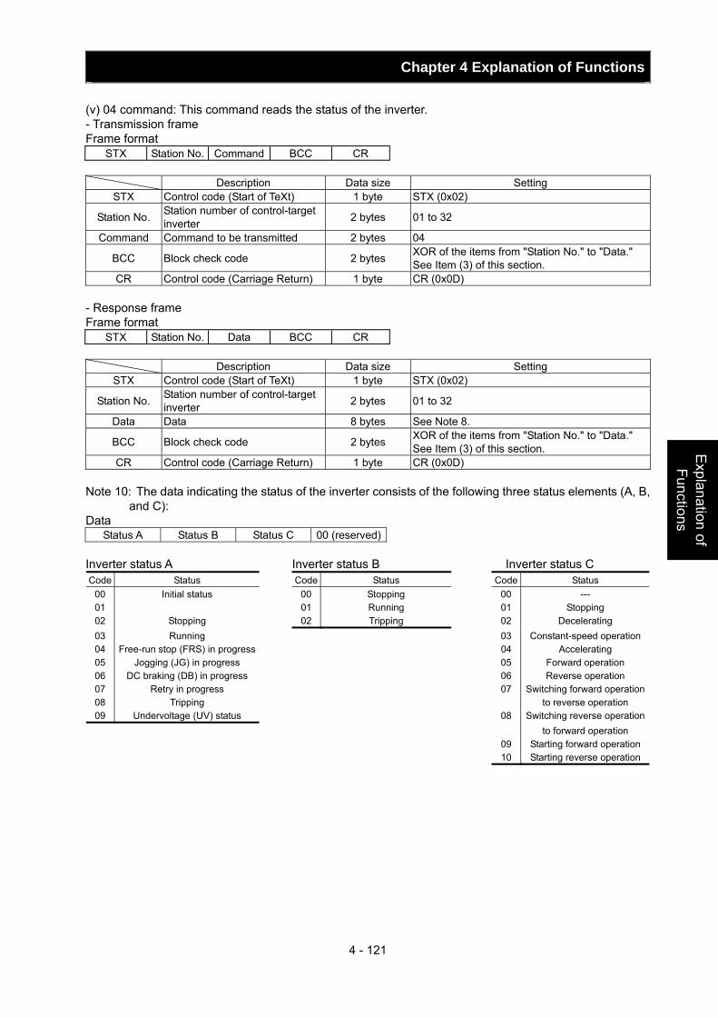
Chapter 4 Explanation of Functions
4 - 121
Explanation of Functions
(v) 04 command: This command reads the status of the inverter. - Transmission frame Frame format
STX Station No. Command BCC CR Description Data size Setting
STX Control code (Start of TeXt) 1 byte STX (0x02)
Station No. Station number of control-target inverter 2 bytes 01 to 32
Command Command to be transmitted 2 bytes 04
BCC Block check code 2 bytes XOR of the items from "Station No." to "Data." See Item (3) of this section.
CR Control code (Carriage Return) 1 byte CR (0x0D) - Response frame Frame format
STX Station No. Data BCC CR Description Data size Setting
STX Control code (Start of TeXt) 1 byte STX (0x02)
Station No. Station number of control-target inverter 2 bytes 01 to 32
Data Data 8 bytes See Note 8.
BCC Block check code 2 bytes XOR of the items from "Station No." to "Data." See Item (3) of this section.
CR Control code (Carriage Return) 1 byte CR (0x0D) Note 10: The data indicating the status of the inverter consists of the following three status elements (A, B,
and C): Data
Status A Status B Status C 00 (reserved) Inverter status A Inverter status B Inverter status C Code Status Code Status Code Status
00 Initial status 00 Stopping 00 --- 01 01 Running 01 Stopping 02 Stopping 02 Tripping 02 Decelerating 03 Running 03 Constant-speed operation04 Free-run stop (FRS) in progress 04 Accelerating 05 Jogging (JG) in progress 05 Forward operation 06 DC braking (DB) in progress 06 Reverse operation 07 Retry in progress 07 Switching forward operation08 Tripping to reverse operation 09 Undervoltage (UV) status 08 Switching reverse operation
to forward operation 09 Starting forward operation
10 Starting reverse operation
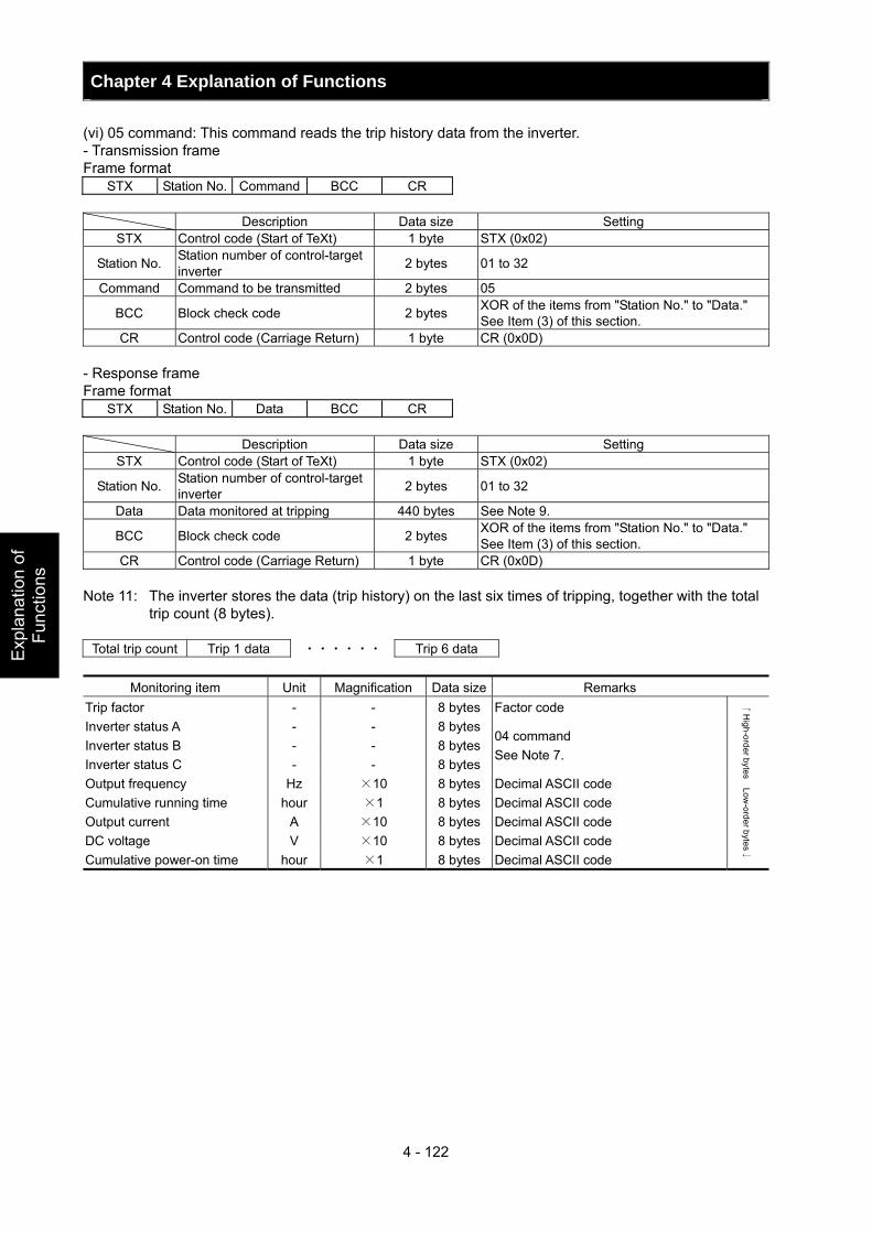
Chapter 4 Explanation of Functions
4 - 122
Exp
lana
tion
of
Func
tions
(vi) 05 command: This command reads the trip history data from the inverter. - Transmission frame Frame format
STX Station No. Command BCC CR Description Data size Setting
STX Control code (Start of TeXt) 1 byte STX (0x02)
Station No. Station number of control-target inverter 2 bytes 01 to 32
Command Command to be transmitted 2 bytes 05
BCC Block check code 2 bytes XOR of the items from "Station No." to "Data." See Item (3) of this section.
CR Control code (Carriage Return) 1 byte CR (0x0D) - Response frame Frame format
STX Station No. Data BCC CR Description Data size Setting
STX Control code (Start of TeXt) 1 byte STX (0x02)
Station No. Station number of control-target inverter 2 bytes 01 to 32
Data Data monitored at tripping 440 bytes See Note 9.
BCC Block check code 2 bytes XOR of the items from "Station No." to "Data." See Item (3) of this section.
CR Control code (Carriage Return) 1 byte CR (0x0D) Note 11: The inverter stores the data (trip history) on the last six times of tripping, together with the total
trip count (8 bytes).
Total trip count Trip 1 data ・・・・・・ Trip 6 data
Monitoring item Unit Magnification Data size Remarks Trip factor - - 8 bytes Factor code Inverter status A - - 8 bytesInverter status B - - 8 bytesInverter status C - - 8 bytes
04 command See Note 7.
Output frequency Hz ×10 8 bytes Decimal ASCII code Cumulative running time hour ×1 8 bytes Decimal ASCII code Output current A ×10 8 bytes Decimal ASCII code DC voltage V ×10 8 bytes Decimal ASCII code Cumulative power-on time hour ×1 8 bytes Decimal ASCII code
↑H
igh-order bytes Low-order bytes
↓
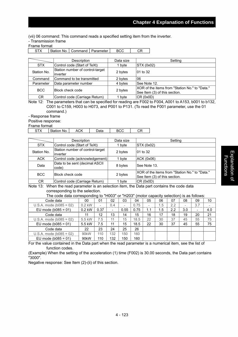
Chapter 4 Explanation of Functions
4 - 123
Explanation of Functions
(vii) 06 command: This command reads a specified setting item from the inverter. - Transmission frame Frame format
STX Station No. Command Parameter BCC CR Description Data size Setting
STX Control code (Start of TeXt) 1 byte STX (0x02)
Station No. Station number of control-target inverter 2 bytes 01 to 32
Command Command to be transmitted 2 bytes 06 Parameter Data parameter number 4 bytes See Note 12.
BCC Block check code 2 bytes XOR of the items from "Station No." to "Data." See Item (3) of this section.
CR Control code (Carriage Return) 1 byte CR (0x0D) Note 12: The parameters that can be specified for reading are F002 to F004, A001 to A153, b001 to b132,
C001 to C159, H003 to H073, and P001 to P131. (To read the F001 parameter, use the 01 command.)
- Response frame Positive response: Frame format
STX Station No. ACK Data BCC CR Description Data size Setting
STX Control code (Start of TeXt) 1 byte STX (0x02)
Station No. Station number of control-target inverter 2 bytes 01 to 32
ACK Control code (acknowledgement) 1 byte ACK (0x06)
Data Data to be sent (decimal ASCII code) 8 bytes See Note 13.
BCC Block check code 2 bytes XOR of the items from "Station No." to "Data." See Item (3) of this section.
CR Control code (Carriage Return) 1 byte CR (0x0D) Note 13: When the read parameter is an selection item, the Data part contains the code data
corresponding to the selection. The code data corresponding to "H003" or "H203" (motor capacity selection) is as follows:
Code data 00 01 02 03 04 05 06 07 08 09 10 U.S.A. mode (b085 = 02) 0.2 kW - 0.4 - 0.75 - 1.5 2.2 - 3.7 -
EU mode (b085 = 01) 0.2 kW 0.37 - 0.55 0.75 1.1 1.5 2.2 3.0 - 4.0Code data 11 12 13 14 15 16 17 18 19 20 21
U.S.A. mode (b085 = 02) 5.5 kW 7.5 11 15 18.5 22 30 37 45 55 75 EU mode (b085 = 01) 5.5 kW 7.5 11 15 18.5 22 30 37 45 55 75
Code data 22 23 24 25 26 U.S.A. mode (b085 = 02) 90kW 110 132 150 160
EU mode (b085 = 01) 90kW 110 132 150 160 For the value contained in the Data part when the read parameter is a numerical item, see the list of
function codes. (Example) When the setting of the acceleration (1) time (F002) is 30.00 seconds, the Data part contains "3000". Negative response: See Item (2)-(ii) of this section.
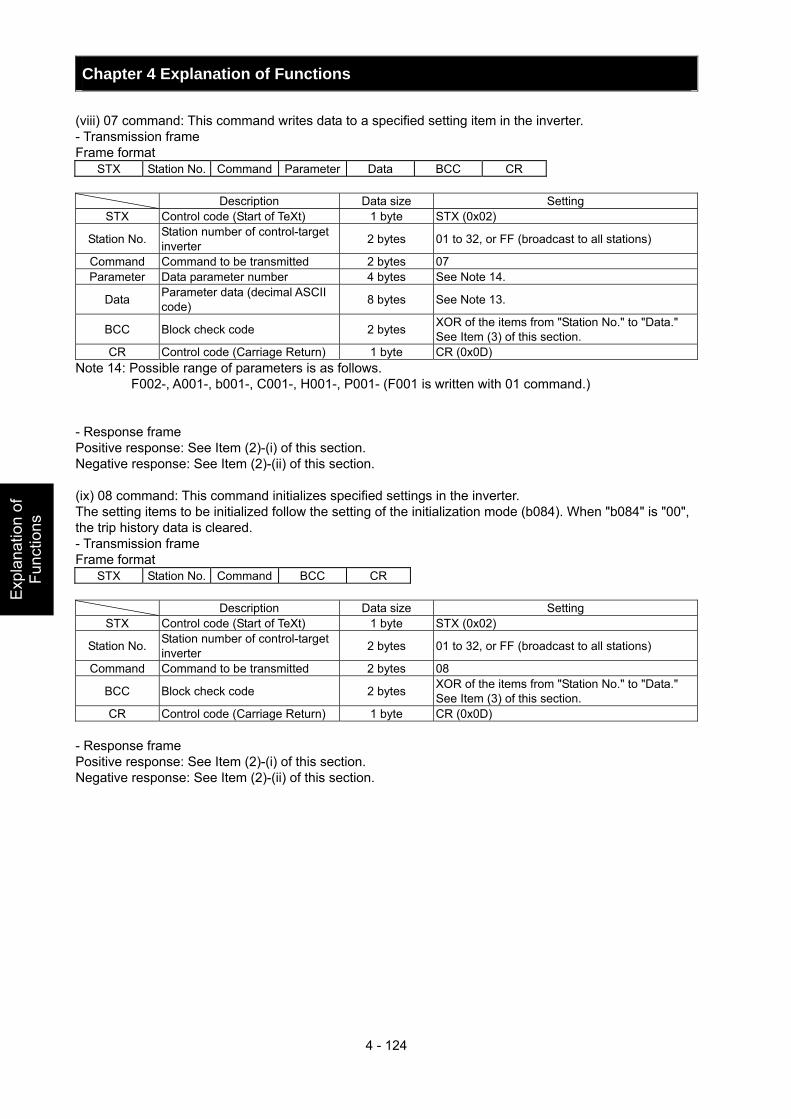
Chapter 4 Explanation of Functions
4 - 124
Exp
lana
tion
of
Func
tions
(viii) 07 command: This command writes data to a specified setting item in the inverter. - Transmission frame Frame format
STX Station No. Command Parameter Data BCC CR Description Data size Setting
STX Control code (Start of TeXt) 1 byte STX (0x02)
Station No. Station number of control-target inverter 2 bytes 01 to 32, or FF (broadcast to all stations)
Command Command to be transmitted 2 bytes 07 Parameter Data parameter number 4 bytes See Note 14.
Data Parameter data (decimal ASCII code) 8 bytes See Note 13.
BCC Block check code 2 bytes XOR of the items from "Station No." to "Data." See Item (3) of this section.
CR Control code (Carriage Return) 1 byte CR (0x0D) Note 14: Possible range of parameters is as follows. F002-, A001-, b001-, C001-, H001-, P001- (F001 is written with 01 command.) - Response frame Positive response: See Item (2)-(i) of this section. Negative response: See Item (2)-(ii) of this section. (ix) 08 command: This command initializes specified settings in the inverter. The setting items to be initialized follow the setting of the initialization mode (b084). When "b084" is "00", the trip history data is cleared. - Transmission frame Frame format
STX Station No. Command BCC CR Description Data size Setting
STX Control code (Start of TeXt) 1 byte STX (0x02)
Station No. Station number of control-target inverter 2 bytes 01 to 32, or FF (broadcast to all stations)
Command Command to be transmitted 2 bytes 08
BCC Block check code 2 bytes XOR of the items from "Station No." to "Data." See Item (3) of this section.
CR Control code (Carriage Return) 1 byte CR (0x0D) - Response frame Positive response: See Item (2)-(i) of this section. Negative response: See Item (2)-(ii) of this section.
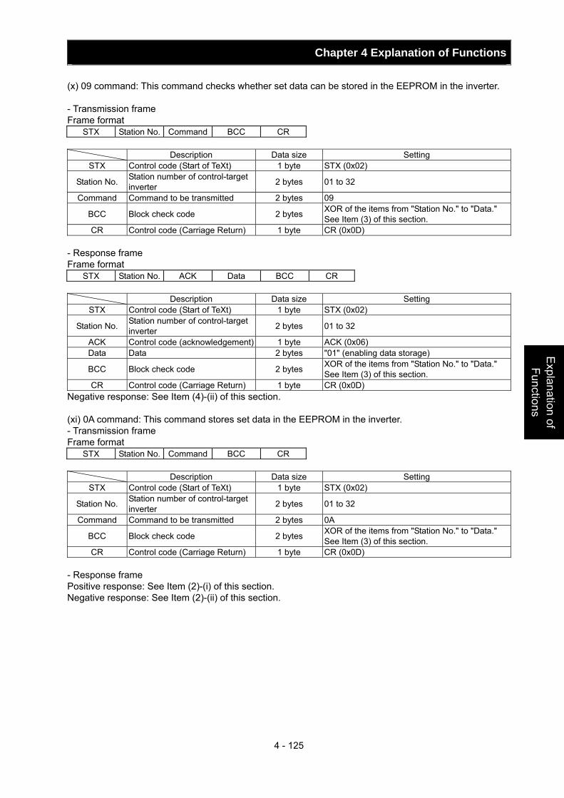
Chapter 4 Explanation of Functions
4 - 125
Explanation of Functions
(x) 09 command: This command checks whether set data can be stored in the EEPROM in the inverter. - Transmission frame Frame format
STX Station No. Command BCC CR Description Data size Setting
STX Control code (Start of TeXt) 1 byte STX (0x02)
Station No. Station number of control-target inverter 2 bytes 01 to 32
Command Command to be transmitted 2 bytes 09
BCC Block check code 2 bytes XOR of the items from "Station No." to "Data." See Item (3) of this section.
CR Control code (Carriage Return) 1 byte CR (0x0D) - Response frame Frame format
STX Station No. ACK Data BCC CR Description Data size Setting
STX Control code (Start of TeXt) 1 byte STX (0x02)
Station No. Station number of control-target inverter 2 bytes 01 to 32
ACK Control code (acknowledgement) 1 byte ACK (0x06) Data Data 2 bytes "01" (enabling data storage)
BCC Block check code 2 bytes XOR of the items from "Station No." to "Data." See Item (3) of this section.
CR Control code (Carriage Return) 1 byte CR (0x0D) Negative response: See Item (4)-(ii) of this section. (xi) 0A command: This command stores set data in the EEPROM in the inverter. - Transmission frame Frame format
STX Station No. Command BCC CR Description Data size Setting
STX Control code (Start of TeXt) 1 byte STX (0x02)
Station No. Station number of control-target inverter 2 bytes 01 to 32
Command Command to be transmitted 2 bytes 0A
BCC Block check code 2 bytes XOR of the items from "Station No." to "Data." See Item (3) of this section.
CR Control code (Carriage Return) 1 byte CR (0x0D) - Response frame Positive response: See Item (2)-(i) of this section. Negative response: See Item (2)-(ii) of this section.
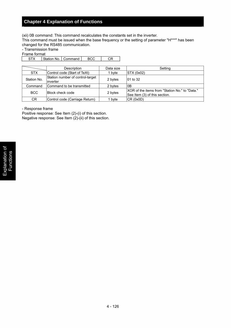
Chapter 4 Explanation of Functions
4 - 126
Exp
lana
tion
of
Func
tions
(xii) 0B command: This command recalculates the constants set in the inverter. This command must be issued when the base frequency or the setting of parameter "H***" has been changed for the RS485 communication. - Transmission frame Frame format
STX Station No. Command BCC CR Description Data size Setting
STX Control code (Start of TeXt) 1 byte STX (0x02)
Station No. Station number of control-target inverter 2 bytes 01 to 32
Command Command to be transmitted 2 bytes 0B
BCC Block check code 2 bytes XOR of the items from "Station No." to "Data." See Item (3) of this section.
CR Control code (Carriage Return) 1 byte CR (0x0D) - Response frame Positive response: See Item (2)-(i) of this section. Negative response: See Item (2)-(ii) of this section.
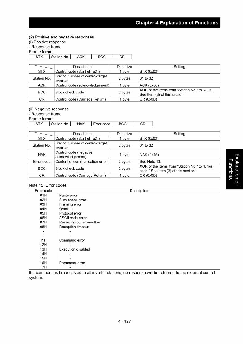
Chapter 4 Explanation of Functions
4 - 127
Explanation of Functions
(2) Positive and negative responses (i) Positive response - Response frame Frame format
STX Station No. ACK BCC CR Description Data size Setting
STX Control code (Start of TeXt) 1 byte STX (0x02)
Station No. Station number of control-target inverter 2 bytes 01 to 32
ACK Control code (acknowledgement) 1 byte ACK (0x06)
BCC Block check code 2 bytes XOR of the items from "Station No." to "ACK." See Item (3) of this section.
CR Control code (Carriage Return) 1 byte CR (0x0D) (ii) Negative response - Response frame Frame format
STX Station No. NAK Error code BCC CR Description Data size Setting
STX Control code (Start of TeXt) 1 byte STX (0x02)
Station No. Station number of control-target inverter 2 bytes 01 to 32
NAK Control code (negative acknowledgement) 1 byte NAK (0x15)
Error code Content of communication error 2 bytes See Note 13.
BCC Block check code 2 bytes XOR of the items from "Station No." to "Error code." See Item (3) of this section.
CR Control code (Carriage Return) 1 byte CR (0x0D) Note 15: Error codes
Error code Description 01H Parity error 02H Sum check error 03H Framing error 04H Overrun 05H Protocol error 06H ASCII code error 07H Receiving-buffer overflow 08H Reception timeout
- - - -
11H Command error 12H - 13H Execution disabled 14H - 15H - 16H Parameter error 17H -
If a command is broadcasted to all inverter stations, no response will be returned to the external control system.
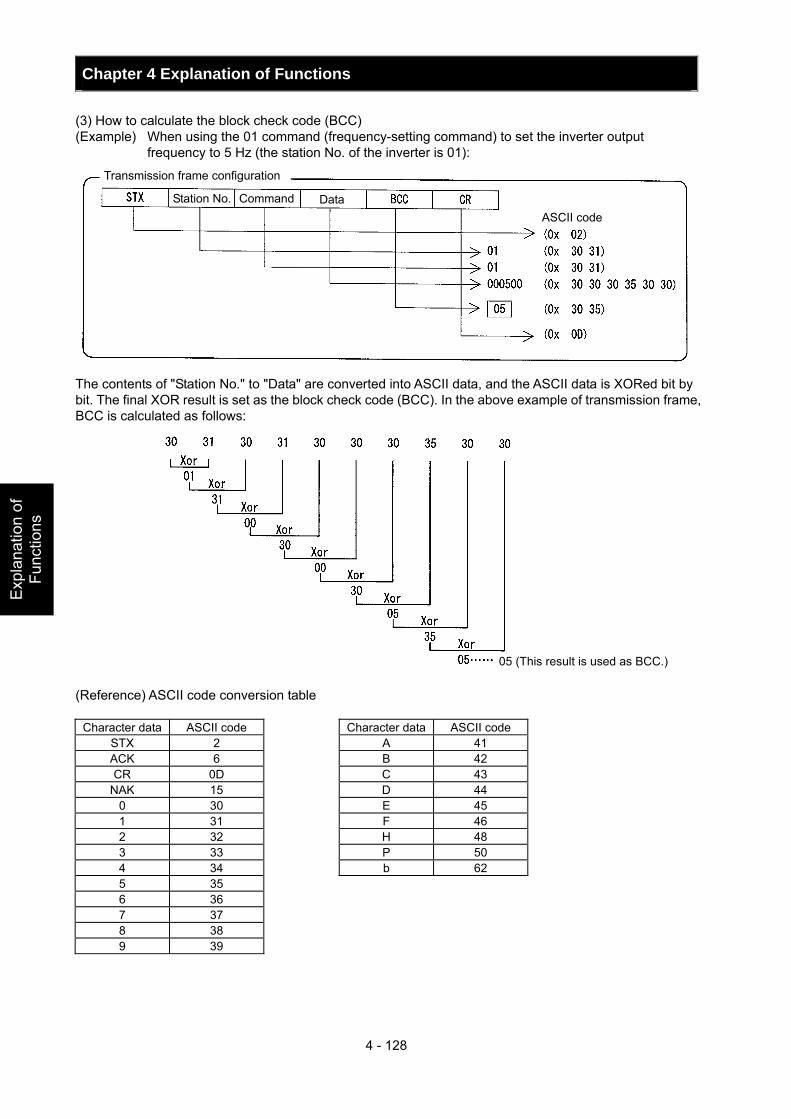
Chapter 4 Explanation of Functions
4 - 128
Exp
lana
tion
of
Func
tions
(3) How to calculate the block check code (BCC) (Example) When using the 01 command (frequency-setting command) to set the inverter output
frequency to 5 Hz (the station No. of the inverter is 01):
The contents of "Station No." to "Data" are converted into ASCII data, and the ASCII data is XORed bit by bit. The final XOR result is set as the block check code (BCC). In the above example of transmission frame, BCC is calculated as follows:
(Reference) ASCII code conversion table
Character data ASCII code Character data ASCII code STX 2 A 41 ACK 6 B 42 CR 0D C 43
NAK 15 D 44 0 30 E 45 1 31 F 46 2 32 H 48 3 33 P 50 4 34 b 62 5 35 6 36 7 37 8 38 9 39
05 (This result is used as BCC.)
Transmission frame configuration
Station No. Command Data ASCII code
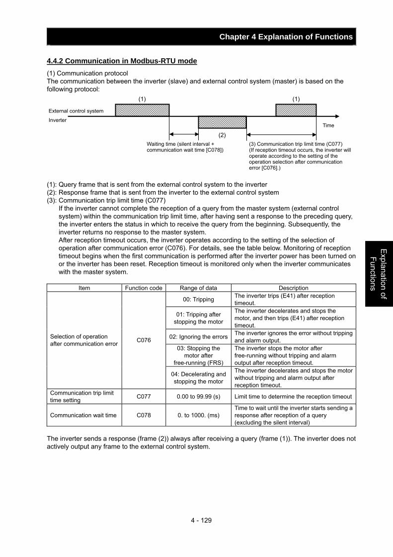
Chapter 4 Explanation of Functions
4 - 129
Explanation of Functions
4.4.2 Communication in Modbus-RTU mode (1) Communication protocol The communication between the inverter (slave) and external control system (master) is based on the following protocol: (1): Query frame that is sent from the external control system to the inverter (2): Response frame that is sent from the inverter to the external control system (3): Communication trip limit time (C077) If the inverter cannot complete the reception of a query from the master system (external control
system) within the communication trip limit time, after having sent a response to the preceding query, the inverter enters the status in which to receive the query from the beginning. Subsequently, the inverter returns no response to the master system.
After reception timeout occurs, the inverter operates according to the setting of the selection of operation after communication error (C076). For details, see the table below. Monitoring of reception timeout begins when the first communication is performed after the inverter power has been turned on or the inverter has been reset. Reception timeout is monitored only when the inverter communicates with the master system.
Item Function code Range of data Description
00: Tripping The inverter trips (E41) after reception timeout.
01: Tripping after stopping the motor
The inverter decelerates and stops the motor, and then trips (E41) after reception timeout.
02: Ignoring the errors The inverter ignores the error without tripping and alarm output.
03: Stopping the motor after
free-running (FRS)
The inverter stops the motor after free-running without tripping and alarm output after reception timeout.
Selection of operation after communication error C076
04: Decelerating and stopping the motor
The inverter decelerates and stops the motor without tripping and alarm output after reception timeout.
Communication trip limit time setting C077 0.00 to 99.99 (s) Limit time to determine the reception timeout
Communication wait time C078 0. to 1000. (ms) Time to wait until the inverter starts sending a response after reception of a query (excluding the silent interval)
The inverter sends a response (frame (2)) always after receiving a query (frame (1)). The inverter does not actively output any frame to the external control system.
(2)
(1)
(1)
External control system
Inverter
Waiting time (silent interval + communication wait time [C078])
(3) Communication trip limit time (C077) (If reception timeout occurs, the inverter will operate according to the setting of the operation selection after communication error [C076].)
Time
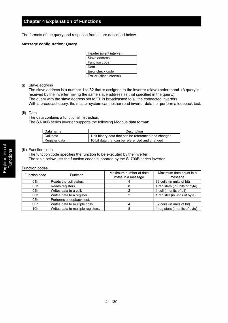
Chapter 4 Explanation of Functions
4 - 130
Exp
lana
tion
of
Func
tions
The formats of the query and response frames are described below. Message configuration: Query
Header (silent interval) Slave address Function code Data Error check code Trailer (silent interval)
(i) Slave address The slave address is a number 1 to 32 that is assigned to the inverter (slave) beforehand. (A query is
received by the inverter having the same slave address as that specified in the query.) The query with the slave address set to "0" is broadcasted to all the connected inverters. With a broadcast query, the master system can neither read inverter data nor perform a loopback test. (ii) Data The data contains a functional instruction. The SJ700B series inverter supports the following Modbus data format:
Data name Description Coil data 1-bit binary data that can be referenced and changed Register data 16-bit data that can be referenced and changed
(iii) Function code The function code specifies the function to be executed by the inverter. The table below lists the function codes supported by the SJ700B series inverter. Function codes
Function code Function Maximum number of data bytes in a message
Maximum data count in a message
01h Reads the coil status. 4 32 coils (in units of bit) 03h Reads registers. 8 4 registers (in units of byte) 05h Writes data to a coil. 2 1 coil (in units of bit) 06h Writes data to a register. 2 1 register (in units of byte) 08h Performs a loopback test. - 0Fh Writes data to multiple coils. 4 32 coils (in units of bit) 10h Writes data to multiple registers. 8 4 registers (in units of byte)
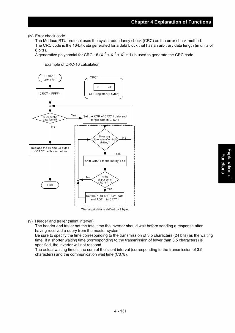
Chapter 4 Explanation of Functions
4 - 131
Explanation of Functions
(iv) Error check code The Modbus-RTU protocol uses the cyclic redundancy check (CRC) as the error check method. The CRC code is the 16-bit data generated for a data block that has an arbitrary data length (in units of
8 bits). A generative polynomial for CRC-16 (X16 + X15 + X2 + 1) is used to generate the CRC code.
Example of CRC-16 calculation
CRC*1 = FFFFh
CRC-16operation
Is the targetdata found?
Set the XOR of CRC*1 data andtarget data in CRC*1
Does anybit remain after 8-bit
shifting?
Shift CRC*1 to the left by 1 bit
Is thebit put out ofCRC*1 "1"?
Replace the Hi and Lo bytesof CRC*1 with each other
End
Set the XOR of CRC*1 dataand A001h in CRC*1
Yes
No
No
Yes
Yes
No
Hi Lo
CRC register (2 bytes)
CRC*1
The target data is shifted by 1 byte. (v) Header and trailer (silent interval) The header and trailer set the total time the inverter should wait before sending a response after
having received a query from the master system. Be sure to specify the time corresponding to the transmission of 3.5 characters (24 bits) as the waiting
time. If a shorter waiting time (corresponding to the transmission of fewer than 3.5 characters) is specified, the inverter will not respond.
The actual waiting time is the sum of the silent interval (corresponding to the transmission of 3.5 characters) and the communication wait time (C078).
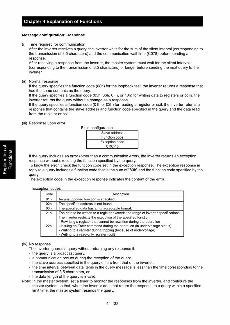
Chapter 4 Explanation of Functions
4 - 132
Exp
lana
tion
of
Func
tions
Message configuration: Response (i) Time required for communication After the inverter receives a query, the inverter waits for the sum of the silent interval (corresponding to
the transmission of 3.5 characters) and the communication wait time (C078) before sending a response.
After receiving a response from the inverter, the master system must wait for the silent interval (corresponding to the transmission of 3.5 characters) or longer before sending the next query to the inverter.
(ii) Normal response If the query specifies the function code (08h) for the loopback test, the inverter returns a response that
has the same contents as the query. If the query specifies a function code (05h, 06h, 0Fh, or 10h) for writing data to registers or coils, the
inverter returns the query without a change as a response. If the query specifies a function code (01h or 03h) for reading a register or coil, the inverter returns a
response that contains the slave address and function code specified in the query and the data read from the register or coil.
(iii) Response upon error
Field configuration Slave address Function code
Exception code CRC-16
If the query includes an error (other than a communication error), the inverter returns an exception response without executing the function specified by the query. To know the error, check the function code set in the exception response. The exception response in reply to a query includes a function code that is the sum of "80h" and the function code specified by the query. The exception code in the exception response indicates the content of the error.
Exception codes
Code Description 01h An unsupported function is specified. 02h The specified address is not found. 03h The specified data has an unacceptable format. 21h The data to be written to a register exceeds the range of inverter specifications.
22h
The inverter restricts the execution of the specified function: - Rewriting a register that cannot be rewritten during the operation - Issuing an Enter command during the operation (in undervoltage status) - Writing to a register during tripping (because of undervoltage) - Writing to a read-only register (coil)
(iv) No response The inverter ignores a query without returning any response if:
- the query is a broadcast query, - a communication occurs during the reception of the query, - the slave address specified in the query differs from that of the inverter, - the time interval between data items in the query message is less than the time corresponding to the
transmission of 3.5 characters, or - the data length of the query is invalid.
Note: In the master system, set a timer to monitor the responses from the inverter, and configure the master system so that, when the inverter does not return the response to a query within a specified limit time, the master system resends the query.
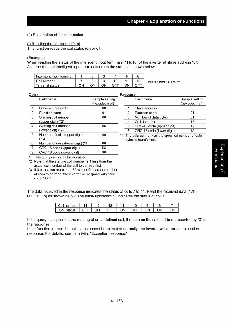
Chapter 4 Explanation of Functions
4 - 133
Explanation of Functions
(4) Explanation of function codes (i) Reading the coil status [01h] This function reads the coil status (on or off). (Example) When reading the status of the intelligent input terminals [1] to [6] of the inverter at slave address "8": Assume that the intelligent input terminals are in the status as shown below.
Intelligent input terminal 1 2 3 4 5 6 Coil number 7 8 9 10 11 12 Terminal status ON ON ON OFF ON OFF
The data received in the response indicates the status of coils 7 to 14. Read the received data (17h = 00010111b) as shown below. The least-significant bit indicates the status of coil 7.
Coil number 14 13 12 11 10 9 8 7 Coil status OFF OFF OFF ON OFF ON ON ON
If the query has specified the reading of an undefined coil, the data on the said coil is represented by "0" in the response. If the function to read the coil status cannot be executed normally, the inverter will return an exception response. For details, see Item (viii), "Exception response."
Coils 13 and 14 are off.
Query Field name Sample setting
(hexadecimal) 1 Slave address (*1) 08 2 Function code 01 3 Starting coil number
(upper digit) (*2) 00
4 Starting coil number (lower digit) (*2)
06
5 Number of coils (upper digit) (*3)
00
6 Number of coils (lower digit) (*3) 06 7 CRC-16 code (upper digit) 5C 8 CRC-16 code (lower digit) 90
*1 This query cannot be broadcasted. *2 Note that the starting coil number is 1 less than the
actual coil number of the coil to be read first. *3 If 0 or a value more than 32 is specified as the number
of coils to be read, the inverter will respond with error code "03h".
Response Field name Sample setting
(hexadecimal) 1 Slave address 08 2 Function code 01 3 Number of data bytes 01 4 Coil data (*4) 17 5 CRC-16 code (upper digit) 12 6 CRC-16 code (lower digit) 1A
*4 The data as many as the specified number of data bytes is transferred.
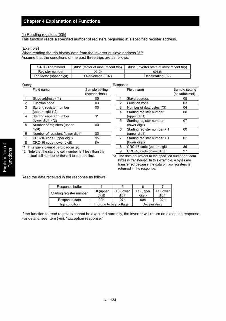
Chapter 4 Explanation of Functions
4 - 134
Exp
lana
tion
of
Func
tions
(ii) Reading registers [03h] This function reads a specified number of registers beginning at a specified register address. (Example) When reading the trip history data from the inverter at slave address "5": Assume that the conditions of the past three trips are as follows:
SJ700B command d081 (factor of most recent trip) d081 (inverter state at most recent trip)Register number 0012h 0013h
Trip factor (upper digit) Overvoltage (E07) Decelerating (02) Read the data received in the response as follows:
Response buffer 4 5 6 7
Starting register number +0 (upper digit)
+0 (lower digit)
+1 (upper digit)
+1 (lower digit)
Response data 00h 07h 00h 02h Trip condition Trip due to overvoltage Decelerating
If the function to read registers cannot be executed normally, the inverter will return an exception response. For details, see Item (viii), "Exception response."
Query Field name Sample setting
(hexadecimal) 1 Slave address (*1) 05 2 Function code 03 3 Starting register number
(upper digit) (*2) 00
4 Starting register number (lower digit) (*2)
11
5 Number of registers (upper digit)
00
6 Number of registers (lower digit) 02 7 CRC-16 code (upper digit) 95 8 CRC-16 code (lower digit) 8A
*1 This query cannot be broadcasted. *2 Note that the starting coil number is 1 less than the
actual coil number of the coil to be read first.
Response Field name Sample setting
(hexadecimal) 1 Slave address 05 2 Function code 03 3 Number of data bytes (*3) 04 4 Starting register number
(upper digit) 00
5 Starting register number (lower digit)
07
6 Starting register number + 1 (upper digit)
00
7 Starting register number + 1 (lower digit)
02
8 CRC-16 code (upper digit) 36 9 CRC-16 code (lower digit) 37
*3 The data equivalent to the specified number of data bytes is transferred. In this example, 4 bytes are transferred because the data on two registers is returned in the response.
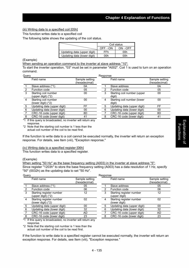
Chapter 4 Explanation of Functions
4 - 135
Explanation of Functions
(iii) Writing data to a specified coil [05h] This function writes data to a specified coil The following table shows the updating of the coil status.
Coil status OFF→ON ON→OFF
Updating data (upper digit) FFh 00h Updating data (lower digit) 00h 00h
(Example) When sending an operation command to the inverter at slave address "10": To start the inverter operation, "03" must be set in parameter "A002". Coil 1 is used to turn on an operation command. If the function to write data to a coil cannot be executed normally, the inverter will return an exception response. For details, see Item (viii), "Exception response." (iv) Writing data to a specified register [06h] This function writes data to a specified register. (Example) When setting "50 Hz" as the base frequency setting (A003) in the inverter at slave address "5": Since register "1203h" to store the base frequency setting (A003) has a data resolution of 1 Hz, specify "50" (0032h) as the updating data to set "50 Hz". If the function to write data to a specified register cannot be executed normally, the inverter will return an exception response. For details, see Item (viii), "Exception response."
Query Field name Sample setting
(hexadecimal) 1 Slave address (*1) 0A 2 Function code 05 3 Starting coil number
(upper digit) (*2) 00
4 Starting coil number (lower digit) (*2)
00
5 Updating data (upper digit) FF 6 Updating data (lower digit) 00 7 CRC-16 code (upper digit) 8D 8 CRC-16 code (lower digit) 41
*1 If this query is broadcasted, no inverter will return any response.
*2 Note that the starting coil number is 1 less than the actual coil number of the coil to be read first.
Response Field name Sample setting
(hexadecimal) 1 Slave address 0A 2 Function code 05 3 Starting coil number (upper
digit) 00
4 Starting coil number (lower digit)
00
5 Updating data (upper digit) FF 6 Updating data (lower digit) 00 7 CRC-16 code (upper digit) 8D 8 CRC-16 code (lower digit) 41
Query Field name Sample setting
(hexadecimal) 1 Slave address (*1) 05 2 Function code 06 3 Starting register number
(upper digit) (*2) 12
4 Starting register number (lower digit) (*2)
02
5 Updating data (upper digit) 00 6 Updating data (lower digit) 32 7 CRC-16 code (upper digit) AD 8 CRC-16 code (lower digit) 23
*1 If this query is broadcasted, no inverter will return any response.
*2 Note that the starting coil number is 1 less than the actual coil number of the coil to be read first.
Response Field name Sample setting
(hexadecimal) 1 Slave address 05 2 Function code 06 3 Starting register number
(upper digit) 12
4 Starting register number (lower digit)
02
5 Updating data (upper digit) 00 6 Updating data (lower digit) 32 7 CRC-16 code (upper digit) AD 8 CRC-16 code (lower digit) 23
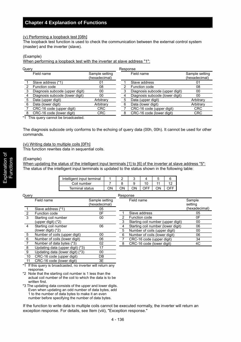
Chapter 4 Explanation of Functions
4 - 136
Exp
lana
tion
of
Func
tions
(v) Performing a loopback test [08h] The loopback test function is used to check the communication between the external control system (master) and the inverter (slave). (Example) When performing a loopback test with the inverter at slave address "1": The diagnosis subcode only conforms to the echoing of query data (00h, 00h). It cannot be used for other commands. (vi) Writing data to multiple coils [0Fh] This function rewrites data in sequential coils. (Example) When updating the status of the intelligent input terminals [1] to [6] of the inverter at slave address "5": The status of the intelligent input terminals is updated to the status shown in the following table:
Intelligent input terminal 1 2 3 4 5 6 Coil number 7 8 9 10 11 12
Terminal status ON ON ON OFF ON OFF If the function to write data to multiple coils cannot be executed normally, the inverter will return an exception response. For details, see Item (viii), "Exception response."
Query Field name Sample setting
(hexadecimal) 1 Slave address (*1) 01 2 Function code 08 3 Diagnosis subcode (upper digit) 00 4 Diagnosis subcode (lower digit) 00 5 Data (upper digit) Arbitrary 6 Data (lower digit) Arbitrary 7 CRC-16 code (upper digit) CRC 8 CRC-16 code (lower digit) CRC
*1 This query cannot be broadcasted.
Response Field name Sample setting
(hexadecimal) 1 Slave address 01 2 Function code 08 3 Diagnosis subcode (upper digit) 00 4 Diagnosis subcode (lower digit) 00 5 Data (upper digit) Arbitrary 6 Data (lower digit) Arbitrary 7 CRC-16 code (upper digit) CRC 8 CRC-16 code (lower digit) CRC
Query Field name Sample setting
(hexadecimal) 1 Slave address (*1) 05 2 Function code 0F 3 Starting coil number
(upper digit) (*2) 00
4 Starting coil number (lower digit) (*2)
06
5 Number of coils (upper digit) 00 6 Number of coils (lower digit) 06 7 Number of data bytes (*3) 02 8 Updating data (upper digit) (*3) 17 9 Updating data (lower digit) (*3) 00 10 CRC-16 code (upper digit) DB 11 CRC-16 code (lower digit) 3E
*1 If this query is broadcasted, no inverter will return any response.
*2 Note that the starting coil number is 1 less than the actual coil number of the coil to which the data is to be written first.
*3 The updating data consists of the upper and lower digits. Even when updating an odd number of data bytes, add 1 to the number of data bytes to make it an even number before specifying the number of data bytes.
Response Field name Sample
setting (hexadecimal)
1 Slave address 05 2 Function code 0F 3 Starting coil number (upper digit) 00 4 Starting coil number (lower digit) 06 5 Number of coils (upper digit) 00 6 Number of coils (lower digit) 06 7 CRC-16 code (upper digit) 34 8 CRC-16 code (lower digit) 4C
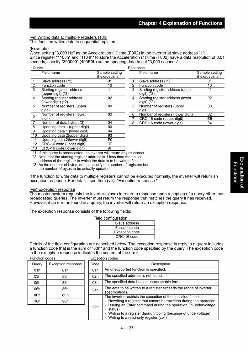
Chapter 4 Explanation of Functions
4 - 137
Explanation of Functions
(vii) Writing data to multiple registers [10h] This function writes data to sequential registers. (Example) When setting "3,000 Hz" as the Acceleration (1) time (F002) in the inverter at slave address "1": Since register "1103h" and "1104h" to store the Acceleration (1) time (F002) have a data resolution of 0.01 seconds, specify "300000" (493E0h) as the updating data to set "3,000 seconds". If the function to write data to multiple registers cannot be executed normally, the inverter will return an exception response. For details, see Item (viii), "Exception response." (viii) Exception response The master system requests the inverter (slave) to return a response upon reception of a query other than broadcasted queries. The inverter must return the response that matches the query it has received. However, if an error is found in a query, the inverter will return an exception response. The exception response consists of the following fields:
Field configuration Slave address Function code
Exception code CRC-16 code
Details of the field configuration are described below. The exception response in reply to a query includes a function code that is the sum of "80h" and the function code specified by the query. The exception code in the exception response indicates the content of the error.
Query Field name Sample setting
(hexadecimal) 1 Slave address (*1) 01 2 Function code 10 3 Starting register address
(upper digit) (*2) 11
4 Starting register address (lower digit) (*2)
02
5 Number of registers (upper digit)
00
6 Number of registers (lower digit)
02
7 Number of data bytes (*3) 04 8 Updating data 1 (upper digit) 00 9 Updating data 1 (lower digit) 04 10 Updating data 2(upper digit) 93 11 Updating data 2(lower digit) E0 12 CRC-16 code (upper digit) 9E 13 CRC-16 code (lower digit) 9F *1 If this query is broadcasted, no inverter will return any response. *2 Note that the starting register address is 1 less than the actual
address of the register to which the data is to be written first. *3 As the number of bytes, do not specify the number of registers but
the number of bytes to be actually updated.
Response Field name Sample setting
(hexadecimal) 1 Slave address (*1) 01 2 Function code 10 3 Starting register address (upper
digit) (*2) 11
4 Starting register address (lower digit) (*2)
02
5 Number of registers (upper digit)
00
6 Number of registers (lower digit) 02 7 CRC-16 code (upper digit) E5 8 CRC-16 code (lower digit) 34
Function codes Query Exception response 01h 81h 03h 83h 05h 85h 06h 86h 0Fh 8Fh 10h 90h
Exception codes Code Description 01h An unsupported function is specified.
02h The specified address is not found.
03h The specified data has an unacceptable format.
21h The data to be written to a register exceeds the range of inverter specifications.
22h
The inverter restricts the execution of the specified function: - Rewriting a register that cannot be rewritten during the operation- Issuing an Enter command during the operation (in undervoltage
status) - Writing to a register during tripping (because of undervoltage) - Writing to a read-only register (coil)
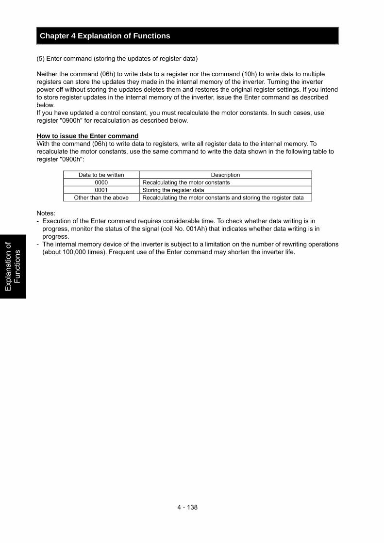
Chapter 4 Explanation of Functions
4 - 138
Exp
lana
tion
of
Func
tions
(5) Enter command (storing the updates of register data) Neither the command (06h) to write data to a register nor the command (10h) to write data to multiple registers can store the updates they made in the internal memory of the inverter. Turning the inverter power off without storing the updates deletes them and restores the original register settings. If you intend to store register updates in the internal memory of the inverter, issue the Enter command as described below. If you have updated a control constant, you must recalculate the motor constants. In such cases, use register "0900h" for recalculation as described below. How to issue the Enter command With the command (06h) to write data to registers, write all register data to the internal memory. To recalculate the motor constants, use the same command to write the data shown in the following table to register "0900h":
Data to be written Description 0000 Recalculating the motor constants 0001 Storing the register data
Other than the above Recalculating the motor constants and storing the register data Notes: - Execution of the Enter command requires considerable time. To check whether data writing is in
progress, monitor the status of the signal (coil No. 001Ah) that indicates whether data writing is in progress.
- The internal memory device of the inverter is subject to a limitation on the number of rewriting operations (about 100,000 times). Frequent use of the Enter command may shorten the inverter life.
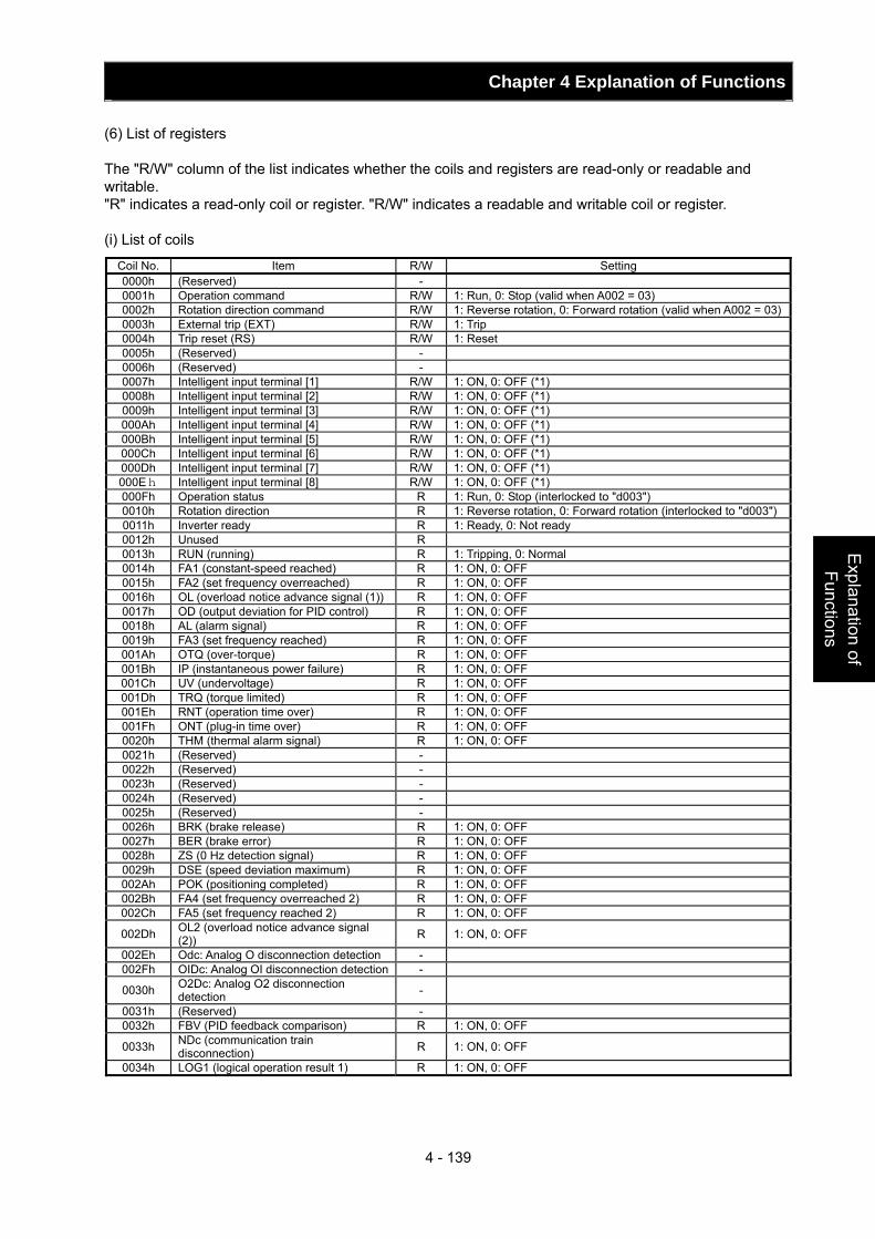
Chapter 4 Explanation of Functions
4 - 139
Explanation of Functions
(6) List of registers The "R/W" column of the list indicates whether the coils and registers are read-only or readable and writable. "R" indicates a read-only coil or register. "R/W" indicates a readable and writable coil or register. (i) List of coils
Coil No. Item R/W Setting 0000h (Reserved) - 0001h Operation command R/W 1: Run, 0: Stop (valid when A002 = 03) 0002h Rotation direction command R/W 1: Reverse rotation, 0: Forward rotation (valid when A002 = 03)0003h External trip (EXT) R/W 1: Trip 0004h Trip reset (RS) R/W 1: Reset 0005h (Reserved) - 0006h (Reserved) - 0007h Intelligent input terminal [1] R/W 1: ON, 0: OFF (*1) 0008h Intelligent input terminal [2] R/W 1: ON, 0: OFF (*1) 0009h Intelligent input terminal [3] R/W 1: ON, 0: OFF (*1) 000Ah Intelligent input terminal [4] R/W 1: ON, 0: OFF (*1) 000Bh Intelligent input terminal [5] R/W 1: ON, 0: OFF (*1) 000Ch Intelligent input terminal [6] R/W 1: ON, 0: OFF (*1) 000Dh Intelligent input terminal [7] R/W 1: ON, 0: OFF (*1) 000Eh Intelligent input terminal [8] R/W 1: ON, 0: OFF (*1) 000Fh Operation status R 1: Run, 0: Stop (interlocked to "d003") 0010h Rotation direction R 1: Reverse rotation, 0: Forward rotation (interlocked to "d003")0011h Inverter ready R 1: Ready, 0: Not ready 0012h Unused R 0013h RUN (running) R 1: Tripping, 0: Normal 0014h FA1 (constant-speed reached) R 1: ON, 0: OFF 0015h FA2 (set frequency overreached) R 1: ON, 0: OFF 0016h OL (overload notice advance signal (1)) R 1: ON, 0: OFF 0017h OD (output deviation for PID control) R 1: ON, 0: OFF 0018h AL (alarm signal) R 1: ON, 0: OFF 0019h FA3 (set frequency reached) R 1: ON, 0: OFF 001Ah OTQ (over-torque) R 1: ON, 0: OFF 001Bh IP (instantaneous power failure) R 1: ON, 0: OFF 001Ch UV (undervoltage) R 1: ON, 0: OFF 001Dh TRQ (torque limited) R 1: ON, 0: OFF 001Eh RNT (operation time over) R 1: ON, 0: OFF 001Fh ONT (plug-in time over) R 1: ON, 0: OFF 0020h THM (thermal alarm signal) R 1: ON, 0: OFF 0021h (Reserved) - 0022h (Reserved) - 0023h (Reserved) - 0024h (Reserved) - 0025h (Reserved) - 0026h BRK (brake release) R 1: ON, 0: OFF 0027h BER (brake error) R 1: ON, 0: OFF 0028h ZS (0 Hz detection signal) R 1: ON, 0: OFF 0029h DSE (speed deviation maximum) R 1: ON, 0: OFF 002Ah POK (positioning completed) R 1: ON, 0: OFF 002Bh FA4 (set frequency overreached 2) R 1: ON, 0: OFF 002Ch FA5 (set frequency reached 2) R 1: ON, 0: OFF
002Dh OL2 (overload notice advance signal (2)) R 1: ON, 0: OFF
002Eh Odc: Analog O disconnection detection - 002Fh OIDc: Analog OI disconnection detection -
0030h O2Dc: Analog O2 disconnection detection -
0031h (Reserved) - 0032h FBV (PID feedback comparison) R 1: ON, 0: OFF
0033h NDc (communication train disconnection) R 1: ON, 0: OFF
0034h LOG1 (logical operation result 1) R 1: ON, 0: OFF
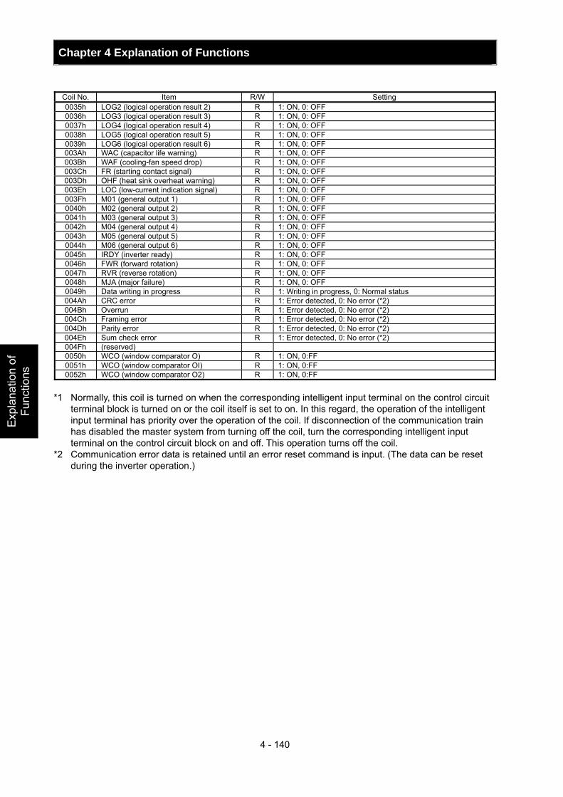
Chapter 4 Explanation of Functions
4 - 140
Exp
lana
tion
of
Func
tions
Coil No. Item R/W Setting 0035h LOG2 (logical operation result 2) R 1: ON, 0: OFF 0036h LOG3 (logical operation result 3) R 1: ON, 0: OFF 0037h LOG4 (logical operation result 4) R 1: ON, 0: OFF 0038h LOG5 (logical operation result 5) R 1: ON, 0: OFF 0039h LOG6 (logical operation result 6) R 1: ON, 0: OFF 003Ah WAC (capacitor life warning) R 1: ON, 0: OFF 003Bh WAF (cooling-fan speed drop) R 1: ON, 0: OFF 003Ch FR (starting contact signal) R 1: ON, 0: OFF 003Dh OHF (heat sink overheat warning) R 1: ON, 0: OFF 003Eh LOC (low-current indication signal) R 1: ON, 0: OFF 003Fh M01 (general output 1) R 1: ON, 0: OFF 0040h M02 (general output 2) R 1: ON, 0: OFF 0041h M03 (general output 3) R 1: ON, 0: OFF 0042h M04 (general output 4) R 1: ON, 0: OFF 0043h M05 (general output 5) R 1: ON, 0: OFF 0044h M06 (general output 6) R 1: ON, 0: OFF 0045h IRDY (inverter ready) R 1: ON, 0: OFF 0046h FWR (forward rotation) R 1: ON, 0: OFF 0047h RVR (reverse rotation) R 1: ON, 0: OFF 0048h MJA (major failure) R 1: ON, 0: OFF 0049h Data writing in progress R 1: Writing in progress, 0: Normal status 004Ah CRC error R 1: Error detected, 0: No error (*2) 004Bh Overrun R 1: Error detected, 0: No error (*2) 004Ch Framing error R 1: Error detected, 0: No error (*2) 004Dh Parity error R 1: Error detected, 0: No error (*2) 004Eh Sum check error R 1: Error detected, 0: No error (*2) 004Fh (reserved) 0050h WCO (window comparator O) R 1: ON, 0:FF 0051h WCO (window comparator OI) R 1: ON, 0:FF 0052h WCO (window comparator O2) R 1: ON, 0:FF
*1 Normally, this coil is turned on when the corresponding intelligent input terminal on the control circuit
terminal block is turned on or the coil itself is set to on. In this regard, the operation of the intelligent input terminal has priority over the operation of the coil. If disconnection of the communication train has disabled the master system from turning off the coil, turn the corresponding intelligent input terminal on the control circuit block on and off. This operation turns off the coil.
*2 Communication error data is retained until an error reset command is input. (The data can be reset during the inverter operation.)
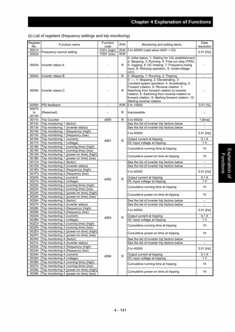
Chapter 4 Explanation of Functions
4 - 141
Explanation of Functions
(ii) List of registers (frequency settings and trip monitoring)
Register No. Function name Function
code R/W Monitoring and setting items Data resolution
0001h F001 (high) R/W0002h Frequency source setting F001 (low) R/W
0 to 40000 (valid when A001 = 03) 0.01 [Hz]
0003h Inverter status A - R
0: Initial status, 1: Waiting for Vdc establishment, 2: Stopping, 3: Running, 4: Free-run stop (FRS), 5: Jogging, 6: DC braking, 7: Frequency being input, 8: Retrying operation, 9: Undervoltage (UV),
-
0004h Inverter status B - R 0: Stopping, 1: Running, 2: Tripping -
0005h Inverter status C - R
0: ---, 1: Stopping, 2: Decelerating, 3: Constant-speed operation, 4: Accelerating, 5: Forward rotation, 6: Reverse rotation, 7: Switching from forward rotation to reverse rotation, 8: Switching from reverse rotation to forward rotation, 9: Starting forward rotation, 10: Starting reverse rotation
-
0006h PID feedback - R/W 0 to 10000 0.01 [%]0007h
to 0010h
(Reserved) - R Inaccessible -
0011h Trip Counter d080 R 0 to 65530 1 [time]0012h Trip monitoring 1 (factor) See the list of inverter trip factors below - 0013h Trip monitoring 1 (inverter status) See the list of inverter trip factors below - 0014h Trip monitoring 1 (frequency) (high) 0015h Trip monitoring 1 (frequency (low) 0 to 40000 0.01 [Hz]
0016h Trip monitoring 1 (current) Output current at tripping 0.1 A 0017h Trip monitoring 1 (voltage) DC input voltage at tripping 1 V 0018h Trip monitoring 1 (running time) (high) 0019h Trip monitoring 1 (running time) (low) Cumulative running time at tripping 1h
001Ah Trip monitoring 1 (power-on time) (high)001Bh Trip monitoring 1 (power-on time) (low)
d081 R
Cumulative power-on time at tripping 1h
001Ch Trip monitoring 2 (factor) See the list of inverter trip factors below - 001Dh Trip monitoring 2 (inverter status) See the list of inverter trip factors below - 001Eh Trip monitoring 2 (frequency) (high) 001Fh Trip monitoring 2 (frequency (low) 0 to 40000 0.01 [Hz]
0020h Trip monitoring 2 (current) Output current at tripping 0.1 A 0021h Trip monitoring 2 (voltage) DC input voltage at tripping 1 V 0022h Trip monitoring 2 (running time) (high) 0023h Trip monitoring 2 (running time) (low) Cumulative running time at tripping 1h
0024h Trip monitoring 2 (power-on time) (high)0025h Trip monitoring 2 (power-on time) (low)
d082 R
Cumulative power-on time at tripping 1h
0026h Trip monitoring 3 (factor) See the list of inverter trip factors below - 0027h Trip monitoring 3 (inverter status) See the list of inverter trip factors below - 0028h Trip monitoring 3 (frequency) (high) 0029h Trip monitoring 3 (frequency (low) 0 to 40000 0.01 [Hz]
002Ah Trip monitoring 3 (current) Output current at tripping 0.1 A 002Bh Trip monitoring 3 (voltage) DC input voltage at tripping 1 V 002Ch Trip monitoring 3 (running time) (high) 002Dh Trip monitoring 3 (running time) (low) Cumulative running time at tripping 1h
002Eh Trip monitoring 3 (power-on time) (high)002Fh Trip monitoring 3 (power-on time) (low)
d083 R
Cumulative power-on time at tripping 1h
0030h Trip monitoring 4 (factor) See the list of inverter trip factors below - 0031h Trip monitoring 4 (inverter status) See the list of inverter trip factors below - 0032h Trip monitoring 4 (frequency) (high) 0033h Trip monitoring 4 (frequency (low) 0 to 40000 0.01 [Hz]
0034h Trip monitoring 4 (current) Output current at tripping 0.1 A 0035h Trip monitoring 4 (voltage) DC input voltage at tripping 1 V 0036h Trip monitoring 4 (running time) (high) 0037h Trip monitoring 4 (running time) (low) Cumulative running time at tripping 1h
0038h Trip monitoring 4 (power-on time) (high)0039h Trip monitoring 4 (power-on time) (low)
d084 R
Cumulative power-on time at tripping 1h
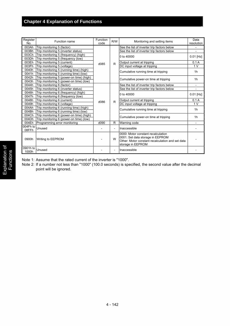
Chapter 4 Explanation of Functions
4 - 142
Exp
lana
tion
of
Func
tions
Register
No. Function name Function code R/W Monitoring and setting items Data
resolution003Ah Trip monitoring 5 (factor) See the list of inverter trip factors below - 003Bh Trip monitoring 5 (inverter status) See the list of inverter trip factors below - 003Ch Trip monitoring 5 (frequency) (high) 003Dh Trip monitoring 5 (frequency (low) 0 to 40000 0.01 [Hz]
003Eh Trip monitoring 5 (current) Output current at tripping 0.1 A 003Fh Trip monitoring 5 (voltage) DC input voltage at tripping 1 V 0040h Trip monitoring 5 (running time) (high) 0041h Trip monitoring 5 (running time) (low) Cumulative running time at tripping 1h
0042h Trip monitoring 5 (power-on time) (high) 0043h Trip monitoring 5 (power-on time) (low)
d085 R
Cumulative power-on time at tripping 1h
0044h Trip monitoring 6 (factor) See the list of inverter trip factors below - 0045h Trip monitoring 6 (inverter status) See the list of inverter trip factors below - 0046h Trip monitoring 6 (frequency) (high) 0047h Trip monitoring 6 (frequency (low) 0 to 40000 0.01 [Hz]
0048h Trip monitoring 6 (current) Output current at tripping 0.1 A 0049h Trip monitoring 6 (voltage) DC input voltage at tripping 1 V 004Ah Trip monitoring 6 (running time) (high) 004Bh Trip monitoring 6 (running time) (low) Cumulative running time at tripping 1h
004Ch Trip monitoring 6 (power-on time) (high) 004Dh Trip monitoring 6 (power-on time) (low)
d086 R
Cumulative power-on time at tripping 1h
004Eh Programming error monitoring d090 R Warning code - 004Fh to 08FFh Unused - - Inaccessible -
0900h Writing to EEPROM - W
0000: Motor constant recalculation 0001: Set data storage in EEPROM Other: Motor constant recalculation and set data storage in EEPROM
-
0901h to 1000h Unused - - Inaccessible -
Note 1: Assume that the rated current of the inverter is "1000". Note 2: If a number not less than "1000" (100.0 seconds) is specified, the second value after the decimal
point will be ignored.
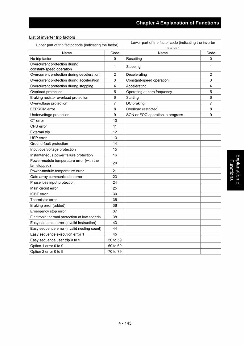
Chapter 4 Explanation of Functions
4 - 143
Explanation of Functions
List of inverter trip factors
Upper part of trip factor code (indicating the factor) Lower part of trip factor code (indicating the inverter
status) Name Code Name Code
No trip factor 0 Resetting 0 Overcurrent protection during constant-speed operation
1 Stopping 1
Overcurrent protection during deceleration 2 Decelerating 2 Overcurrent protection during acceleration 3 Constant-speed operation 3 Overcurrent protection during stopping 4 Accelerating 4 Overload protection 5 Operating at zero frequency 5 Braking resistor overload protection 6 Starting 6 Overvoltage protection 7 DC braking 7 EEPROM error 8 Overload restricted 8 Undervoltage protection 9 SON or FOC operation in progress 9 CT error 10 CPU error 11 External trip 12 USP error 13 Ground-fault protection 14 Input overvoltage protection 15 Instantaneous power failure protection 16 Power-module temperature error (with the fan stopped)
20
Power-module temperature error 21 Gate array communication error 23 Phase loss input protection 24 Main circuit error 25 IGBT error 30 Thermistor error 35 Braking error (added) 36 Emergency stop error 37 Electronic thermal protection at low speeds 38 Easy sequence error (invalid instruction) 43 Easy sequence error (invalid nesting count) 44 Easy sequence execution error 1 45 Easy sequence user trip 0 to 9 50 to 59 Option 1 error 0 to 9 60 to 69 Option 2 error 0 to 9 70 to 79
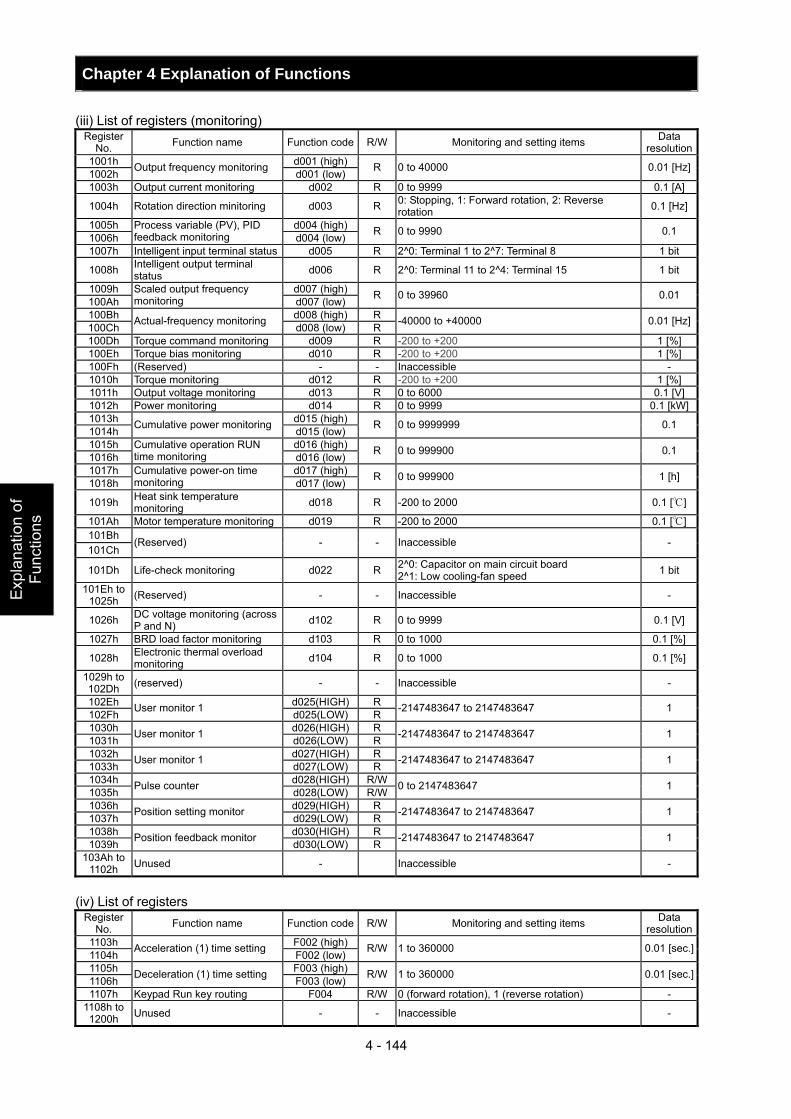
Chapter 4 Explanation of Functions
4 - 144
Exp
lana
tion
of
Func
tions
(iii) List of registers (monitoring) Register
No. Function name Function code R/W Monitoring and setting items Data resolution
1001h d001 (high)1002h Output frequency monitoring d001 (low) R 0 to 40000 0.01 [Hz]
1003h Output current monitoring d002 R 0 to 9999 0.1 [A]
1004h Rotation direction minitoring d003 R 0: Stopping, 1: Forward rotation, 2: Reverse rotation 0.1 [Hz]
1005h d004 (high)1006h
Process variable (PV), PID feedback monitoring d004 (low) R 0 to 9990 0.1
1007h Intelligent input terminal status d005 R 2^0: Terminal 1 to 2^7: Terminal 8 1 bit
1008h Intelligent output terminal status d006 R 2^0: Terminal 11 to 2^4: Terminal 15 1 bit
1009h d007 (high)100Ah
Scaled output frequency monitoring d007 (low) R 0 to 39960 0.01
100Bh d008 (high) R 100Ch Actual-frequency monitoring d008 (low) R -40000 to +40000 0.01 [Hz]
100Dh Torque command monitoring d009 R -200 to +200 1 [%] 100Eh Torque bias monitoring d010 R -200 to +200 1 [%] 100Fh (Reserved) - - Inaccessible - 1010h Torque monitoring d012 R -200 to +200 1 [%] 1011h Output voltage monitoring d013 R 0 to 6000 0.1 [V] 1012h Power monitoring d014 R 0 to 9999 0.1 [kW]1013h d015 (high)1014h Cumulative power monitoring d015 (low) R 0 to 9999999 0.1
1015h d016 (high)1016h
Cumulative operation RUN time monitoring d016 (low) R 0 to 999900 0.1
1017h d017 (high)1018h
Cumulative power-on time monitoring d017 (low) R 0 to 999900 1 [h]
1019h Heat sink temperature monitoring d018 R -200 to 2000 0.1 []
101Ah Motor temperature monitoring d019 R -200 to 2000 0.1 []101Bh 101Ch
(Reserved) - - Inaccessible -
101Dh Life-check monitoring d022 R 2^0: Capacitor on main circuit board 2^1: Low cooling-fan speed 1 bit
101Eh to 1025h (Reserved) - - Inaccessible -
1026h DC voltage monitoring (across P and N) d102 R 0 to 9999 0.1 [V]
1027h BRD load factor monitoring d103 R 0 to 1000 0.1 [%]
1028h Electronic thermal overload monitoring d104 R 0 to 1000 0.1 [%]
1029h to 102Dh (reserved) - - Inaccessible -
102Eh d025(HIGH) R 102Fh User monitor 1 d025(LOW) R -2147483647 to 2147483647 1
1030h d026(HIGH) R 1031h User monitor 1 d026(LOW) R -2147483647 to 2147483647 1
1032h d027(HIGH) R 1033h User monitor 1 d027(LOW) R -2147483647 to 2147483647 1
1034h d028(HIGH) R/W1035h Pulse counter d028(LOW) R/W 0 to 2147483647 1
1036h d029(HIGH) R 1037h Position setting monitor d029(LOW) R -2147483647 to 2147483647 1
1038h d030(HIGH) R 1039h Position feedback monitor d030(LOW) R -2147483647 to 2147483647 1
103Ah to 1102h Unused - Inaccessible -
(iv) List of registers
Register No. Function name Function code R/W Monitoring and setting items Data
resolution1103h F002 (high)1104h Acceleration (1) time setting F002 (low) R/W 1 to 360000 0.01 [sec.]
1105h F003 (high)1106h Deceleration (1) time setting F003 (low) R/W 1 to 360000 0.01 [sec.]
1107h Keypad Run key routing F004 R/W 0 (forward rotation), 1 (reverse rotation) - 1108h to 1200h Unused - - Inaccessible -
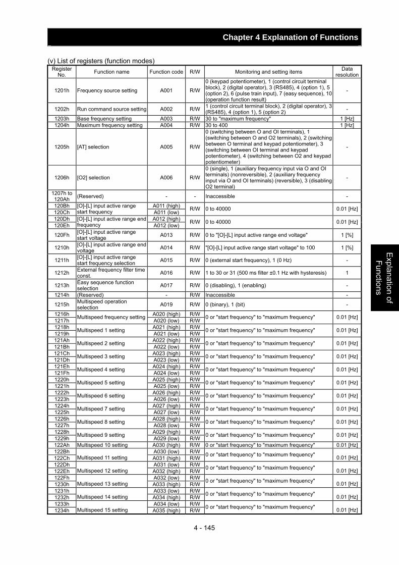
Chapter 4 Explanation of Functions
4 - 145
Explanation of Functions
(v) List of registers (function modes) Register
No. Function name Function code R/W Monitoring and setting items Data resolution
1201h Frequency source setting A001 R/W
0 (keypad potentiometer), 1 (control circuit terminal block), 2 (digital operator), 3 (RS485), 4 (option 1), 5 (option 2), 6 (pulse train input), 7 (easy sequence), 10 (operation function result)
-
1202h Run command source setting A002 R/W 1 (control circuit terminal block), 2 (digital operator), 3 (RS485), 4 (option 1), 5 (option 2) -
1203h Base frequency setting A003 R/W 30 to "maximum frequency" 1 [Hz] 1204h Maximum frequency setting A004 R/W 30 to 400 1 [Hz]
1205h [AT] selection A005 R/W
0 (switching between O and OI terminals), 1 (switching between O and O2 terminals), 2 (switching between O terminal and keypad potentiometer), 3 (switching between OI terminal and keypad potentiometer), 4 (switching between O2 and keypad potentiometer)
-
1206h [O2] selection A006 R/W
0 (single), 1 (auxiliary frequency input via O and OI terminals) (nonreversible), 2 (auxiliary frequency input via O and OI terminals) (reversible), 3 (disabling O2 terminal)
-
1207h to 120Ah (Reserved) - - Inaccessible -
120Bh A011 (high)120Ch
[O]-[L] input active range start frequency A011 (low) R/W 0 to 40000 0.01 [Hz]
120Dh A012 (high)120Eh
[O]-[L] input active range end frequency A012 (low) R/W 0 to 40000 0.01 [Hz]
120Fh [O]-[L] input active range start voltage A013 R/W 0 to "[O]-[L] input active range end voltage" 1 [%]
1210h [O]-[L] input active range end voltage A014 R/W "[O]-[L] input active range start voltage" to 100 1 [%]
1211h [O]-[L] input active range start frequency selection A015 R/W 0 (external start frequency), 1 (0 Hz) -
1212h External frequency filter time const. A016 R/W 1 to 30 or 31 (500 ms filter ±0.1 Hz with hysteresis) 1
1213h Easy sequence function selection A017 R/W 0 (disabling), 1 (enabling) -
1214h (Reserved) - R/W Inaccessible -
1215h Multispeed operation selection A019 R/W 0 (binary), 1 (bit) -
1216h A020 (high) R/W1217h Multispeed frequency setting A020 (low) R/W 0 or "start frequency" to "maximum frequency" 0.01 [Hz]
1218h A021 (high) R/W1219h Multispeed 1 setting A021 (low) R/W 0 or "start frequency" to "maximum frequency" 0.01 [Hz]
121Ah A022 (high) R/W121Bh Multispeed 2 setting A022 (low) R/W 0 or "start frequency" to "maximum frequency" 0.01 [Hz]
121Ch A023 (high) R/W121Dh Multispeed 3 setting A023 (low) R/W 0 or "start frequency" to "maximum frequency" 0.01 [Hz]
121Eh A024 (high) R/W121Fh Multispeed 4 setting A024 (low) R/W 0 or "start frequency" to "maximum frequency" 0.01 [Hz]
1220h A025 (high) R/W1221h Multispeed 5 setting A025 (low) R/W 0 or "start frequency" to "maximum frequency" 0.01 [Hz]
1222h A026 (high) R/W1223h Multispeed 6 setting A026 (low) R/W 0 or "start frequency" to "maximum frequency" 0.01 [Hz]
1224h A027 (high) R/W1225h Multispeed 7 setting A027 (low) R/W 0 or "start frequency" to "maximum frequency" 0.01 [Hz]
1226h A028 (high) R/W1227h Multispeed 8 setting A028 (low) R/W 0 or "start frequency" to "maximum frequency" 0.01 [Hz]
1228h A029 (high) R/W1229h Multispeed 9 setting A029 (low) R/W 0 or "start frequency" to "maximum frequency" 0.01 [Hz]
122Ah Multispeed 10 setting A030 (high) R/W 0 or "start frequency" to "maximum frequency" 0.01 [Hz]122Bh A030 (low) R/W122Ch
Multispeed 11 setting A031 (high) R/W 0 or "start frequency" to "maximum frequency"
0.01 [Hz]122Dh A031 (low) R/W122Eh
Multispeed 12 setting A032 (high) R/W 0 or "start frequency" to "maximum frequency"
0.01 [Hz]122Fh A032 (low) R/W1230h
Multispeed 13 setting A033 (high) R/W 0 or "start frequency" to "maximum frequency"
0.01 [Hz]1231h A033 (low) R/W1232h
Multispeed 14 setting A034 (high) R/W 0 or "start frequency" to "maximum frequency"
0.01 [Hz]1233h A034 (low) R/W1234h
Multispeed 15 setting A035 (high) R/W 0 or "start frequency" to "maximum frequency"
0.01 [Hz]
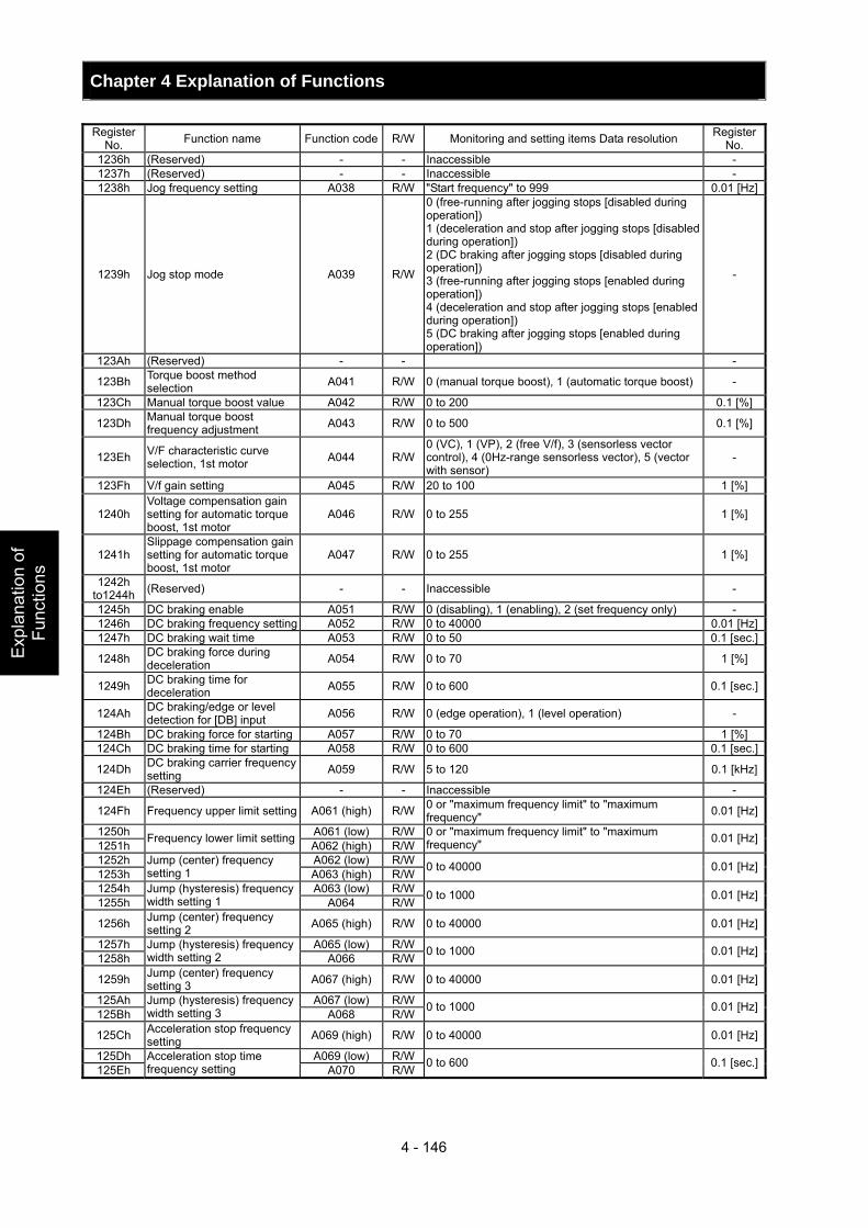
Chapter 4 Explanation of Functions
4 - 146
Exp
lana
tion
of
Func
tions
Register No. Function name Function code R/W Monitoring and setting items Data resolution Register
No. 1236h (Reserved) - - Inaccessible - 1237h (Reserved) - - Inaccessible - 1238h Jog frequency setting A038 R/W "Start frequency" to 999 0.01 [Hz]
1239h Jog stop mode A039 R/W
0 (free-running after jogging stops [disabled during operation]) 1 (deceleration and stop after jogging stops [disabled during operation]) 2 (DC braking after jogging stops [disabled during operation]) 3 (free-running after jogging stops [enabled during operation]) 4 (deceleration and stop after jogging stops [enabled during operation]) 5 (DC braking after jogging stops [enabled during operation])
-
123Ah (Reserved) - - -
123Bh Torque boost method selection A041 R/W 0 (manual torque boost), 1 (automatic torque boost) -
123Ch Manual torque boost value A042 R/W 0 to 200 0.1 [%]
123Dh Manual torque boost frequency adjustment A043 R/W 0 to 500 0.1 [%]
123Eh V/F characteristic curve selection, 1st motor A044 R/W
0 (VC), 1 (VP), 2 (free V/f), 3 (sensorless vector control), 4 (0Hz-range sensorless vector), 5 (vector with sensor)
-
123Fh V/f gain setting A045 R/W 20 to 100 1 [%]
1240h Voltage compensation gain setting for automatic torque boost, 1st motor
A046 R/W 0 to 255 1 [%]
1241h Slippage compensation gain setting for automatic torque boost, 1st motor
A047 R/W 0 to 255 1 [%]
1242h to1244h (Reserved) - - Inaccessible -
1245h DC braking enable A051 R/W 0 (disabling), 1 (enabling), 2 (set frequency only) - 1246h DC braking frequency setting A052 R/W 0 to 40000 0.01 [Hz]1247h DC braking wait time A053 R/W 0 to 50 0.1 [sec.]
1248h DC braking force during deceleration A054 R/W 0 to 70 1 [%]
1249h DC braking time for deceleration A055 R/W 0 to 600 0.1 [sec.]
124Ah DC braking/edge or level detection for [DB] input A056 R/W 0 (edge operation), 1 (level operation) -
124Bh DC braking force for starting A057 R/W 0 to 70 1 [%] 124Ch DC braking time for starting A058 R/W 0 to 600 0.1 [sec.]
124Dh DC braking carrier frequency setting A059 R/W 5 to 120 0.1 [kHz]
124Eh (Reserved) - - Inaccessible -
124Fh Frequency upper limit setting A061 (high) R/W 0 or "maximum frequency limit" to "maximum frequency" 0.01 [Hz]
1250h A061 (low) R/W1251h Frequency lower limit setting A062 (high) R/W
0 or "maximum frequency limit" to "maximum frequency" 0.01 [Hz]
1252h A062 (low) R/W1253h
Jump (center) frequency setting 1 A063 (high) R/W 0 to 40000 0.01 [Hz]
1254h A063 (low) R/W1255h
Jump (hysteresis) frequency width setting 1 A064 R/W 0 to 1000 0.01 [Hz]
1256h Jump (center) frequency setting 2 A065 (high) R/W 0 to 40000 0.01 [Hz]
1257h A065 (low) R/W1258h
Jump (hysteresis) frequency width setting 2 A066 R/W 0 to 1000 0.01 [Hz]
1259h Jump (center) frequency setting 3 A067 (high) R/W 0 to 40000 0.01 [Hz]
125Ah A067 (low) R/W125Bh
Jump (hysteresis) frequency width setting 3 A068 R/W 0 to 1000 0.01 [Hz]
125Ch Acceleration stop frequency setting A069 (high) R/W 0 to 40000 0.01 [Hz]
125Dh A069 (low) R/W125Eh
Acceleration stop time frequency setting A070 R/W 0 to 600 0.1 [sec.]
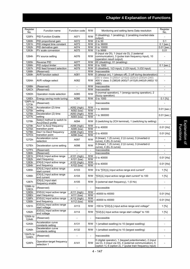
Chapter 4 Explanation of Functions
4 - 147
Explanation of Functions
Register
No. Function name Function code R/W Monitoring and setting items Data resolution Register No.
125Fh PID Function Enable A071 R/W 0 (disabling), 1 (enabling), 2 (enabling inverted-data output) -
1260h PID proportional gain A072 R/W 2 to 50 0.1 1261h PID integral time constant A073 R/W 0 to 36000 0.1 [sec.]1262h PID derivative gain A074 R/W 0 to 10000 0.01 [sec.]1263h PV scale conversion A075 R/W 1 to 9999 0.01
1264h PV source setting A076 R/W0 (input via OI), 1 (input via O), 2 (external communication), 3 (pulse train frequency input), 10 (operation result output)
-
1265h Reverse PID A077 R/W 00 (disabling), 01 (enabling) - 1266h PID output limiter A078 R/W 0 to 1000 0.1 [sec.]1267h PID feed forward selection A079 R/W 0 (disabled), 1(O input), 2 (OI input), 3 (O2 input) - 1268h (Reserved) - R/W Inaccessible - 1269h AVR function select A081 R/W 0 (always on), 1 (always off), 2 (off during deceleration) -
126Ah AVR voltage select A082 R/W200 V class: 0 (200)/1 (215)/2 (220)/3 (230)/4 (240) 400 V class: 5 (380)/6 (400)/7 (415)/8 (440)/9 (460)/ 10 (480)
-
126Bh (Reserved) - R/W Inaccessible - 126Ch (Reserved) - R/W Inaccessible -
126Dh Operation mode selection A085 R/W 0 (normal operation), 1 (energy-saving operation), 2 (fuzzy operation) -
126Eh Energy saving mode tuning A086 R/W 0 to 1000 0.1 [%]126Fh to
1273h (Reserved) - - Inaccessible -
1274h A092 (high) R/W1275h
Acceleration (2) time setting A092 (low) R/W 1 to 360000 0.01 [sec.]
1276h A093 (high) R/W1277h
Deceleration (2) time setting A093 (low) R/W 1 to 360000 0.01 [sec.]
1278h Select method to switch to Acc2/Dec2 profile A094 R/W 0 (switching by 2CH terminal), 1 (switching by setting) -
1279h A095 (high) R/W127Ah
Acc1 to Acc2 frequency transition point A095 (low) R/W 0 to 40000 0.01 [Hz]
127Bh A096 (high) R/W127Ch
Dec1 to Dec2 frequency transition point A096 (low) R/W 0 to 40000 0.01 [Hz]
127Dh Acceleration curve selection A097 R/W 0 (linear), 1 (S curve), 2 (U curve), 3 (inverted-U
curve), 4 (EL-S curve) -
127Eh Deceleration curve setting A098 R/W 0 (linear), 1 (S curve), 2 (U curve), 3 (inverted-U curve), 4 (EL-S curve) -
127Fh (Reserved) - - Inaccessible - 1280h (Reserved) - - Inaccessible - 1281h A101 (high) R/W1282h
[OI]-[L] input active range start frequency A101 (low) R/W 0 to 40000 0.01 [Hz]
1283h A102 (high) R/W1284h
[OI]-[L] input active range end frequency A102 (low) R/W 0 to 40000 0.01 [Hz]
1285h [OI]-[L] input active range start current A103 R/W 0 to "[OI]-[L] input active range end current" 1 [%]
1286h [OI]-[L] input active range end current A104 R/W "[OI]-[L] input active range start current" to 100 1 [%]
1287h [OI]-[L] input start frequency enable A105 R/W 0 (external start frequency), 1 (0 Hz) -
1288h to 128Ch (Reserved) - - Inaccessible -
128Dh A111 (high) R/W128Eh
[O2]-[L] input active range start frequency A111 (low) R/W -40000 to 40000 0.01 [Hz]
128Fh A112 (high) R/W1290h
[O2]-[L] input active range end frequency A112 (low) R/W -40000 to 40000 0.01 [Hz]
1291h [O2]-[L] input active range start voltage A113 R/W -100 to "[O2]-[L] input active range end voltage" 1 [%]
1292h [O2]-[L] input active range end voltage A114 R/W "[O2]-[L] input active range start voltage" to 100 1 [%]
1293h to 12A4h (Reserved) - - Inaccessible -
12A5h Acceleration curve constants setting A131 R/W 1 (smallest swelling) to 10 (largest swelling) -
12A6h Deceleration curve constants setting A132 R/W 1 (smallest swelling) to 10 (largest swelling) -
12A7h to 12AEh (Reserved) - - Inaccessible -
12AFh Operation-target frequency selection 1 A141 R/W
0 (digital operator), 1 (keypad potentiometer), 2 (input via O), 3 (input via OI), 4 (external communication), 5 (option 1), 6 (option 2), 7 (pulse train frequency input)
-
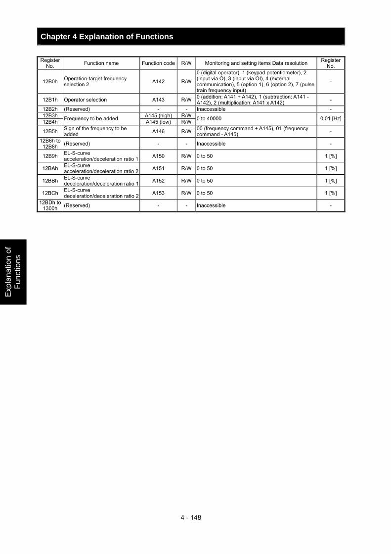
Chapter 4 Explanation of Functions
4 - 148
Exp
lana
tion
of
Func
tions
Register
No. Function name Function code R/W Monitoring and setting items Data resolution Register No.
12B0h Operation-target frequency selection 2 A142 R/W
0 (digital operator), 1 (keypad potentiometer), 2 (input via O), 3 (input via OI), 4 (external communication), 5 (option 1), 6 (option 2), 7 (pulse train frequency input)
-
12B1h Operator selection A143 R/W 0 (addition: A141 + A142), 1 (subtraction: A141 - A142), 2 (multiplication: A141 x A142) -
12B2h (Reserved) - - Inaccessible - 12B3h A145 (high) R/W12B4h Frequency to be added A145 (low) R/W 0 to 40000 0.01 [Hz]
12B5h Sign of the frequency to be added A146 R/W 00 (frequency command + A145), 01 (frequency
command - A145) -
12B6h to 12B8h (Reserved) - - Inaccessible -
12B9h EL-S-curve acceleration/deceleration ratio 1 A150 R/W 0 to 50 1 [%]
12BAh EL-S-curve acceleration/deceleration ratio 2 A151 R/W 0 to 50 1 [%]
12BBh EL-S-curve deceleration/deceleration ratio 1 A152 R/W 0 to 50 1 [%]
12BCh EL-S-curve deceleration/deceleration ratio 2 A153 R/W 0 to 50 1 [%]
12BDh to 1300h (Reserved) - - Inaccessible -
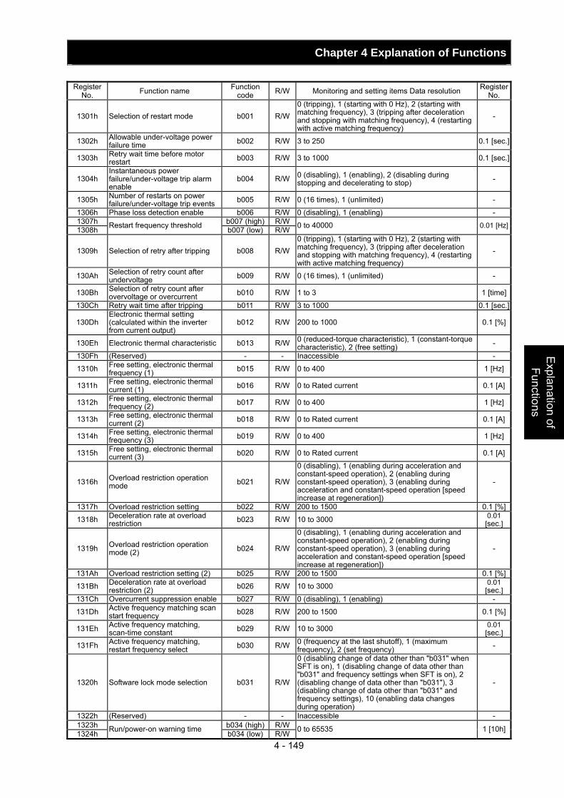
Chapter 4 Explanation of Functions
4 - 149
Explanation of Functions
Register
No. Function name Function code R/W Monitoring and setting items Data resolution Register
No.
1301h Selection of restart mode b001 R/W0 (tripping), 1 (starting with 0 Hz), 2 (starting with matching frequency), 3 (tripping after deceleration and stopping with matching frequency), 4 (restarting with active matching frequency)
-
1302h Allowable under-voltage power failure time b002 R/W 3 to 250 0.1 [sec.]
1303h Retry wait time before motor restart b003 R/W 3 to 1000 0.1 [sec.]
1304h Instantaneous power failure/under-voltage trip alarm enable
b004 R/W 0 (disabling), 1 (enabling), 2 (disabling during stopping and decelerating to stop) -
1305h Number of restarts on power failure/under-voltage trip events b005 R/W 0 (16 times), 1 (unlimited) -
1306h Phase loss detection enable b006 R/W 0 (disabling), 1 (enabling) - 1307h b007 (high) R/W1308h Restart frequency threshold b007 (low) R/W 0 to 40000 0.01 [Hz]
1309h Selection of retry after tripping b008 R/W0 (tripping), 1 (starting with 0 Hz), 2 (starting with matching frequency), 3 (tripping after deceleration and stopping with matching frequency), 4 (restarting with active matching frequency)
-
130Ah Selection of retry count after undervoltage b009 R/W 0 (16 times), 1 (unlimited) -
130Bh Selection of retry count after overvoltage or overcurrent b010 R/W 1 to 3 1 [time]
130Ch Retry wait time after tripping b011 R/W 3 to 1000 0.1 [sec.]
130Dh Electronic thermal setting (calculated within the inverter from current output)
b012 R/W 200 to 1000 0.1 [%]
130Eh Electronic thermal characteristic b013 R/W 0 (reduced-torque characteristic), 1 (constant-torque characteristic), 2 (free setting) -
130Fh (Reserved) - - Inaccessible -
1310h Free setting, electronic thermal frequency (1) b015 R/W 0 to 400 1 [Hz]
1311h Free setting, electronic thermal current (1) b016 R/W 0 to Rated current 0.1 [A]
1312h Free setting, electronic thermal frequency (2) b017 R/W 0 to 400 1 [Hz]
1313h Free setting, electronic thermal current (2) b018 R/W 0 to Rated current 0.1 [A]
1314h Free setting, electronic thermal frequency (3) b019 R/W 0 to 400 1 [Hz]
1315h Free setting, electronic thermal current (3) b020 R/W 0 to Rated current 0.1 [A]
1316h Overload restriction operation mode b021 R/W
0 (disabling), 1 (enabling during acceleration and constant-speed operation), 2 (enabling during constant-speed operation), 3 (enabling during acceleration and constant-speed operation [speed increase at regeneration])
-
1317h Overload restriction setting b022 R/W 200 to 1500 0.1 [%]
1318h Deceleration rate at overload restriction b023 R/W 10 to 3000 0.01
[sec.]
1319h Overload restriction operation mode (2) b024 R/W
0 (disabling), 1 (enabling during acceleration and constant-speed operation), 2 (enabling during constant-speed operation), 3 (enabling during acceleration and constant-speed operation [speed increase at regeneration])
-
131Ah Overload restriction setting (2) b025 R/W 200 to 1500 0.1 [%]
131Bh Deceleration rate at overload restriction (2) b026 R/W 10 to 3000 0.01
[sec.]131Ch Overcurrent suppression enable b027 R/W 0 (disabling), 1 (enabling) -
131Dh Active frequency matching scan start frequency b028 R/W 200 to 1500 0.1 [%]
131Eh Active frequency matching, scan-time constant b029 R/W 10 to 3000 0.01
[sec.]
131Fh Active frequency matching, restart frequency select b030 R/W 0 (frequency at the last shutoff), 1 (maximum
frequency), 2 (set frequency) -
1320h Software lock mode selection b031 R/W
0 (disabling change of data other than "b031" when SFT is on), 1 (disabling change of data other than "b031" and frequency settings when SFT is on), 2 (disabling change of data other than "b031"), 3 (disabling change of data other than "b031" and frequency settings), 10 (enabling data changes during operation)
-
1322h (Reserved) - - Inaccessible - 1323h b034 (high) R/W1324h Run/power-on warning time b034 (low) R/W 0 to 65535 1 [10h]
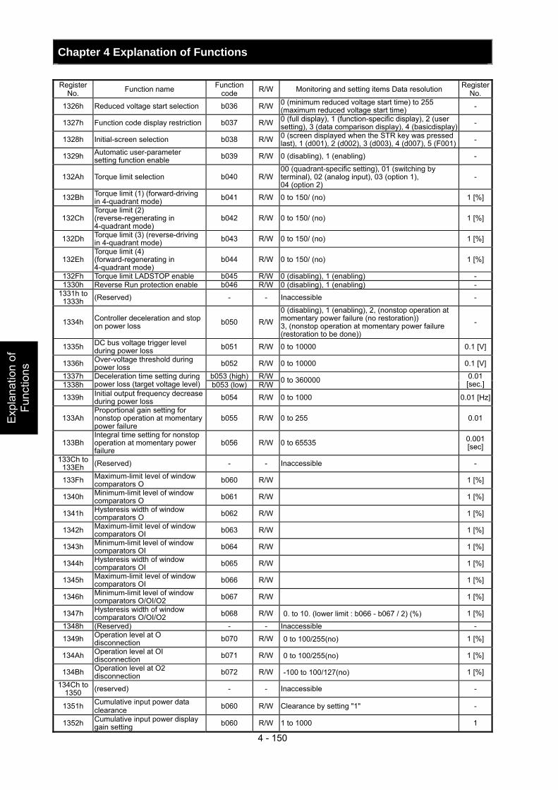
Chapter 4 Explanation of Functions
4 - 150
Exp
lana
tion
of
Func
tions
Register No. Function name Function
code R/W Monitoring and setting items Data resolution Register No.
1326h Reduced voltage start selection b036 R/W 0 (minimum reduced voltage start time) to 255 (maximum reduced voltage start time) -
1327h Function code display restriction b037 R/W 0 (full display), 1 (function-specific display), 2 (user setting), 3 (data comparison display), 4 (basicdisplay) -
1328h Initial-screen selection b038 R/W 0 (screen displayed when the STR key was pressed last), 1 (d001), 2 (d002), 3 (d003), 4 (d007), 5 (F001) -
1329h Automatic user-parameter setting function enable b039 R/W 0 (disabling), 1 (enabling) -
132Ah Torque limit selection b040 R/W00 (quadrant-specific setting), 01 (switching by terminal), 02 (analog input), 03 (option 1), 04 (option 2)
-
132Bh Torque limit (1) (forward-driving in 4-quadrant mode) b041 R/W 0 to 150/ (no) 1 [%]
132Ch Torque limit (2) (reverse-regenerating in 4-quadrant mode)
b042 R/W 0 to 150/ (no) 1 [%]
132Dh Torque limit (3) (reverse-driving in 4-quadrant mode) b043 R/W 0 to 150/ (no) 1 [%]
132Eh Torque limit (4) (forward-regenerating in 4-quadrant mode)
b044 R/W 0 to 150/ (no) 1 [%]
132Fh Torque limit LADSTOP enable b045 R/W 0 (disabling), 1 (enabling) - 1330h Reverse Run protection enable b046 R/W 0 (disabling), 1 (enabling) -
1331h to 1333h (Reserved) - - Inaccessible -
1334h Controller deceleration and stop on power loss b050 R/W
0 (disabling), 1 (enabling), 2, (nonstop operation at momentary power failure (no restoration)) 3, (nonstop operation at momentary power failure (restoration to be done))
-
1335h DC bus voltage trigger level during power loss b051 R/W 0 to 10000 0.1 [V]
1336h Over-voltage threshold during power loss b052 R/W 0 to 10000 0.1 [V]
1337h b053 (high) R/W1338h
Deceleration time setting during power loss (target voltage level) b053 (low) R/W 0 to 360000 0.01
[sec.]
1339h Initial output frequency decrease during power loss b054 R/W 0 to 1000 0.01 [Hz]
133Ah Proportional gain setting for nonstop operation at momentary power failure
b055 R/W 0 to 255 0.01
133Bh Integral time setting for nonstop operation at momentary power failure
b056 R/W 0 to 65535 0.001 [sec]
133Ch to 133Eh (Reserved) - - Inaccessible -
133Fh Maximum-limit level of window comparators O b060 R/W 1 [%]
1340h Minimum-limit level of window comparators O b061 R/W 1 [%]
1341h Hysteresis width of window comparators O b062 R/W 1 [%]
1342h Maximum-limit level of window comparators OI b063 R/W 1 [%]
1343h Minimum-limit level of window comparators OI b064 R/W 1 [%]
1344h Hysteresis width of window comparators OI b065 R/W 1 [%]
1345h Maximum-limit level of window comparators OI b066 R/W 1 [%]
1346h Minimum-limit level of window comparators O/OI/O2 b067 R/W 1 [%]
1347h Hysteresis width of window comparators O/OI/O2 b068 R/W 0. to 10. (lower limit : b066 - b067 / 2) (%) 1 [%]
1348h (Reserved) - - Inaccessible -
1349h Operation level at O disconnection b070 R/W 0 to 100/255(no) 1 [%]
134Ah Operation level at OI disconnection b071 R/W 0 to 100/255(no) 1 [%]
134Bh Operation level at O2 disconnection b072 R/W -100 to 100/127(no) 1 [%]
134Ch to 1350 (reserved) - - Inaccessible -
1351h Cumulative input power data clearance b060 R/W Clearance by setting "1" -
1352h Cumulative input power display gain setting b060 R/W 1 to 1000 1
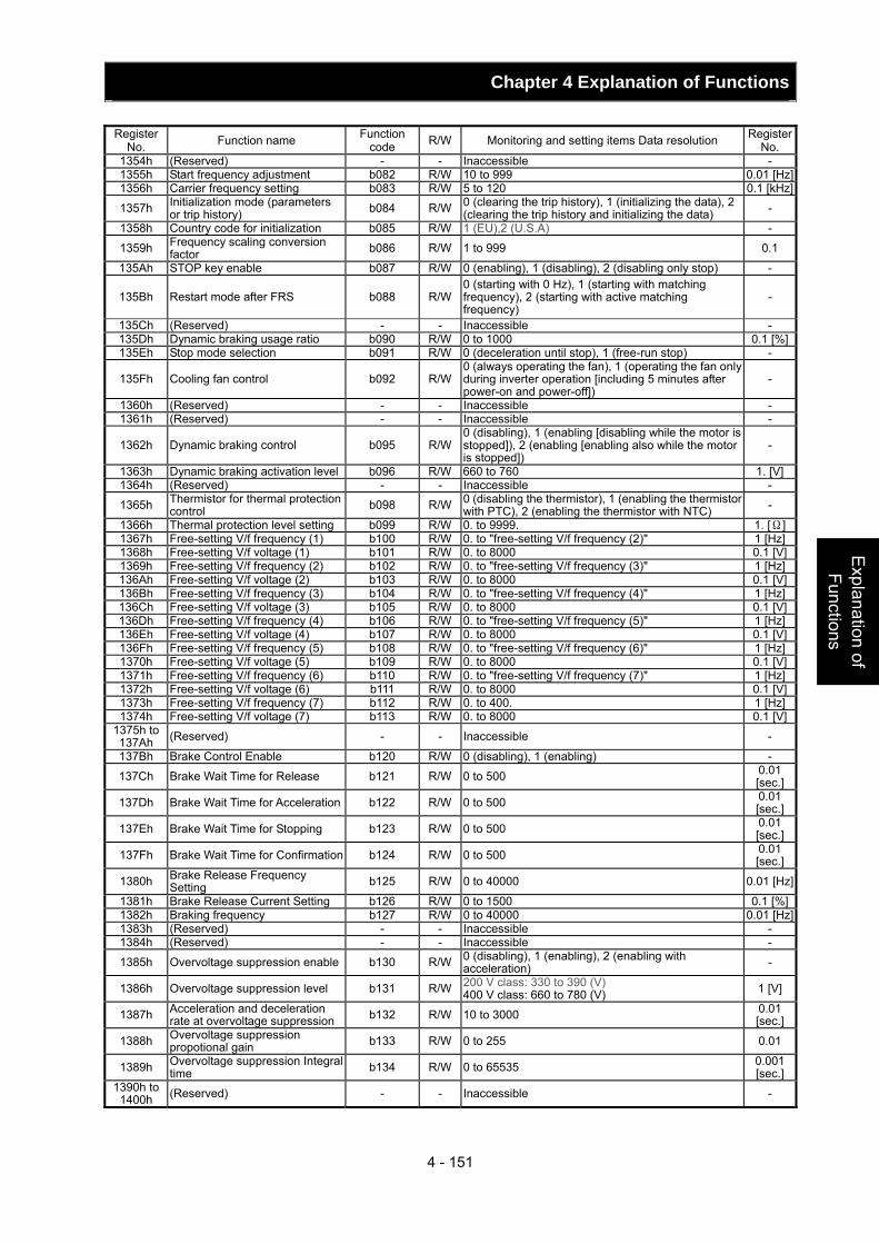
Chapter 4 Explanation of Functions
4 - 151
Explanation of Functions
Register No. Function name Function
code R/W Monitoring and setting items Data resolution Register No.
1354h (Reserved) - - Inaccessible - 1355h Start frequency adjustment b082 R/W 10 to 999 0.01 [Hz]1356h Carrier frequency setting b083 R/W 5 to 120 0.1 [kHz]
1357h Initialization mode (parameters or trip history) b084 R/W 0 (clearing the trip history), 1 (initializing the data), 2
(clearing the trip history and initializing the data) -
1358h Country code for initialization b085 R/W 1 (EU),2 (U.S.A) -
1359h Frequency scaling conversion factor b086 R/W 1 to 999 0.1
135Ah STOP key enable b087 R/W 0 (enabling), 1 (disabling), 2 (disabling only stop) -
135Bh Restart mode after FRS b088 R/W0 (starting with 0 Hz), 1 (starting with matching frequency), 2 (starting with active matching frequency)
-
135Ch (Reserved) - - Inaccessible - 135Dh Dynamic braking usage ratio b090 R/W 0 to 1000 0.1 [%]135Eh Stop mode selection b091 R/W 0 (deceleration until stop), 1 (free-run stop) -
135Fh Cooling fan control b092 R/W0 (always operating the fan), 1 (operating the fan only during inverter operation [including 5 minutes after power-on and power-off])
-
1360h (Reserved) - - Inaccessible - 1361h (Reserved) - - Inaccessible -
1362h Dynamic braking control b095 R/W0 (disabling), 1 (enabling [disabling while the motor is stopped]), 2 (enabling [enabling also while the motor is stopped])
-
1363h Dynamic braking activation level b096 R/W 660 to 760 1. [V]1364h (Reserved) - - Inaccessible -
1365h Thermistor for thermal protection control b098 R/W 0 (disabling the thermistor), 1 (enabling the thermistor
with PTC), 2 (enabling the thermistor with NTC) -
1366h Thermal protection level setting b099 R/W 0. to 9999. 1. [Ω]1367h Free-setting V/f frequency (1) b100 R/W 0. to "free-setting V/f frequency (2)" 1 [Hz]1368h Free-setting V/f voltage (1) b101 R/W 0. to 8000 0.1 [V]1369h Free-setting V/f frequency (2) b102 R/W 0. to "free-setting V/f frequency (3)" 1 [Hz]136Ah Free-setting V/f voltage (2) b103 R/W 0. to 8000 0.1 [V]136Bh Free-setting V/f frequency (3) b104 R/W 0. to "free-setting V/f frequency (4)" 1 [Hz]136Ch Free-setting V/f voltage (3) b105 R/W 0. to 8000 0.1 [V]136Dh Free-setting V/f frequency (4) b106 R/W 0. to "free-setting V/f frequency (5)" 1 [Hz]136Eh Free-setting V/f voltage (4) b107 R/W 0. to 8000 0.1 [V]136Fh Free-setting V/f frequency (5) b108 R/W 0. to "free-setting V/f frequency (6)" 1 [Hz]1370h Free-setting V/f voltage (5) b109 R/W 0. to 8000 0.1 [V]1371h Free-setting V/f frequency (6) b110 R/W 0. to "free-setting V/f frequency (7)" 1 [Hz]1372h Free-setting V/f voltage (6) b111 R/W 0. to 8000 0.1 [V]1373h Free-setting V/f frequency (7) b112 R/W 0. to 400. 1 [Hz]1374h Free-setting V/f voltage (7) b113 R/W 0. to 8000 0.1 [V]
1375h to 137Ah (Reserved) - - Inaccessible -
137Bh Brake Control Enable b120 R/W 0 (disabling), 1 (enabling) -
137Ch Brake Wait Time for Release b121 R/W 0 to 500 0.01 [sec.]
137Dh Brake Wait Time for Acceleration b122 R/W 0 to 500 0.01 [sec.]
137Eh Brake Wait Time for Stopping b123 R/W 0 to 500 0.01 [sec.]
137Fh Brake Wait Time for Confirmation b124 R/W 0 to 500 0.01 [sec.]
1380h Brake Release Frequency Setting b125 R/W 0 to 40000 0.01 [Hz]
1381h Brake Release Current Setting b126 R/W 0 to 1500 0.1 [%]1382h Braking frequency b127 R/W 0 to 40000 0.01 [Hz]1383h (Reserved) - - Inaccessible - 1384h (Reserved) - - Inaccessible -
1385h Overvoltage suppression enable b130 R/W 0 (disabling), 1 (enabling), 2 (enabling with acceleration) -
1386h Overvoltage suppression level b131 R/W 200 V class: 330 to 390 (V) 400 V class: 660 to 780 (V) 1 [V]
1387h Acceleration and deceleration rate at overvoltage suppression b132 R/W 10 to 3000 0.01
[sec.]
1388h Overvoltage suppression propotional gain b133 R/W 0 to 255 0.01
1389h Overvoltage suppression Integral time b134 R/W 0 to 65535 0.001
[sec.]1390h to
1400h (Reserved) - - Inaccessible -
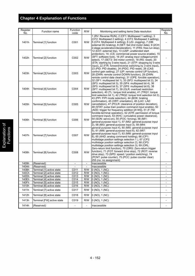
Chapter 4 Explanation of Functions
4 - 152
Exp
lana
tion
of
Func
tions
Register
No. Function name Function code R/W Monitoring and setting items Data resolution Register
No.
1401h Terminal [1] function C001 R/W -
1402h Terminal [2] function C002 R/W -
1403h Terminal [3] function C003 R/W -
1404h Terminal [4] function C004 R/W -
1405h Terminal [5] function C005 R/W -
1406h Terminal [6] function C006 R/W -
1407h Terminal [7] function C007 R/W -
1408h Terminal [8] function C008 R/W
1 (RV: Reverse RUN), 2 (CF1: Multispeed 1 setting), 3 (CF2: Multispeed 2 setting), 4 (CF3: Multispeed 3 setting), 5 (CF4: Multispeed 4 setting), 6 (JG: Jogging), 7 (DB: external DC braking), 8 (SET: Set 2nd motor data), 9 (2CH: 2-stage acceleration/deceleration), 11 (FRS: free-run stop), 12 (EXT: external trip), 13 (USP: unattended start protection), 14: (CS: commercial power source enable), 15 (SFT: software lock), 16 (AT: analog input voltage/current select), 17 (SET3: 3rd motor control), 18 (RS: reset), 20 (STA: starting by 3-wire input), 21 (STP: stopping by 3-wire input), 22 (F/R: forward/reverse switching by 3-wire input), 23 (PID: PID disable), 24 (PIDC: PID reset), 26 (CAS: control gain setting), 27 (UP: remote control UP function), 28 (DWN: remote control DOWN function), 29 (DWN: remote control data clearing), 31 (OPE: forcible operation), 32 (SF1: multispeed bit 1), 33 (SF2: multispeed bit 2), 34 (SF3: multispeed bit 3), 35 (SF4: multispeed bit 4), 36 (SF5: multispeed bit 5), 37 (SF6: multispeed bit 6), 38 (SF7: multispeed bit 7), 39 (OLR: overload restriction selection), 40 (TL: torque limit enable), 41 (TRQ1: torque limit selection bit 1), 42 (TRQ2: torque limit selection bit 2), 43 (PPI: P/PI mode selection), 44 (BOK: braking confirmation), 45 (ORT: orientation), 46 (LAC: LAD cancellation), 47 (PCLR: clearance of position deviation), 48 (STAT: pulse train position command input enable), 50 (ADD: trigger for frequency addition [A145]), 51 (F-TM: forcible-terminal operation), 52 (ATR: permission of torque command input), 53 (KHC: cumulative power clearance), 54 (SON: servo-on), 55 (FOC: forcing), 56 (MI1: general-purpose input 1), 57 (MI2: general-purpose input 2), 58 (MI3: general-purpose input 3), 59 (MI4: general-purpose input 4), 60 (MI5: general-purpose input 5), 61 (MI6: general-purpose input 6), 62 (MI7: general-purpose input 7), 63 (MI8: general-purpose input 8), 65 (AHD: analog command holding), 66 (CP1: multistage position settings selection 1 ), 67 (CP2: multistage position settings selection 2), 68 (CP3: multistage position settings selection 3), 69 (ORL: Zero-return limit function), 70 (ORG: Zero-return trigger function), 71 (FOT: forward drive stop), 72 (ROT: reverse drive stop), 73 (SPD: speed / position switching), 74 (PCNT: pulse counter), 75 (PCC: pulse counter clear) 255 (no: no assignment)
-
1409h (Reserved) - - Inaccessible - 140Ah (Reserved) - - Inaccessible - 140Bh Terminal [1] active state C011 R/W 0 (NO), 1 (NC) - 140Ch Terminal [2] active state C012 R/W 0 (NO), 1 (NC) - 140Dh Terminal [3] active state C013 R/W 0 (NO), 1 (NC) - 140Eh Terminal [4] active state C014 R/W 0 (NO), 1 (NC) - 140Fh Terminal [5] active state C015 R/W 0 (NO), 1 (NC) - 1410h Terminal [6] active state C016 R/W 0 (NO), 1 (NC) - 1411h Terminal [7] active state C017 R/W 0 (NO), 1 (NC) -
1412h Terminal [8] active state C018 R/W 0 (NO), 1 (NC) -
1413h Terminal [FW] active state C019 R/W 0 (NO), 1 (NC) -
1414h (Reserved) - - Inaccessible -
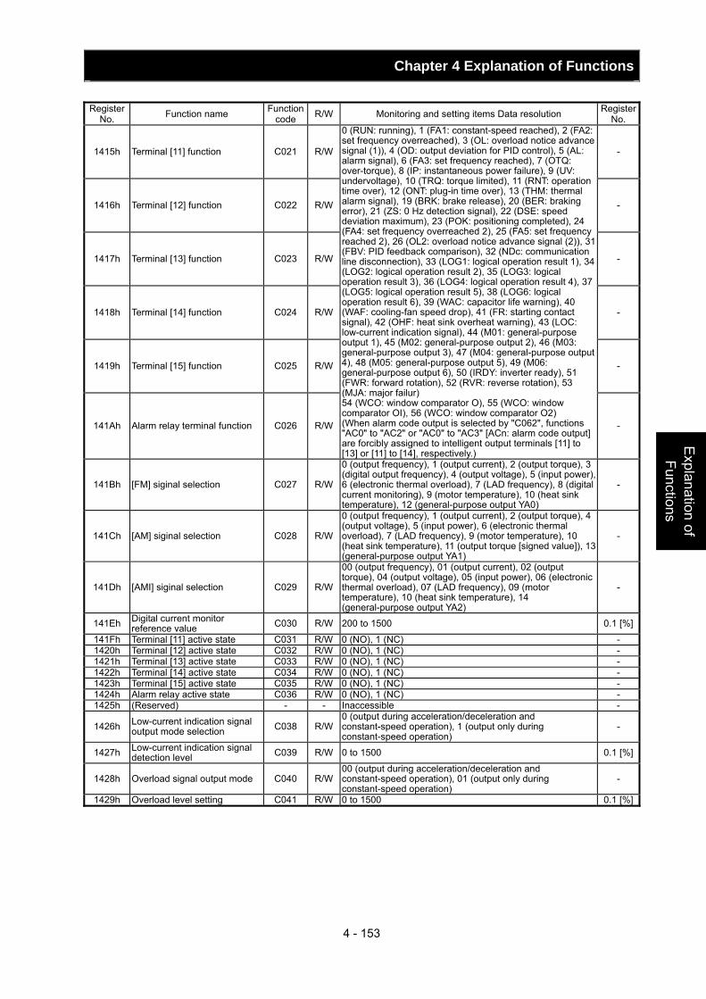
Chapter 4 Explanation of Functions
4 - 153
Explanation of Functions
Register
No. Function name Function code R/W Monitoring and setting items Data resolution Register
No.
1415h Terminal [11] function C021 R/W -
1416h Terminal [12] function C022 R/W -
1417h Terminal [13] function C023 R/W -
1418h Terminal [14] function C024 R/W -
1419h Terminal [15] function C025 R/W -
141Ah Alarm relay terminal function C026 R/W
0 (RUN: running), 1 (FA1: constant-speed reached), 2 (FA2: set frequency overreached), 3 (OL: overload notice advance signal (1)), 4 (OD: output deviation for PID control), 5 (AL: alarm signal), 6 (FA3: set frequency reached), 7 (OTQ: over-torque), 8 (IP: instantaneous power failure), 9 (UV: undervoltage), 10 (TRQ: torque limited), 11 (RNT: operation time over), 12 (ONT: plug-in time over), 13 (THM: thermal alarm signal), 19 (BRK: brake release), 20 (BER: braking error), 21 (ZS: 0 Hz detection signal), 22 (DSE: speed deviation maximum), 23 (POK: positioning completed), 24 (FA4: set frequency overreached 2), 25 (FA5: set frequency reached 2), 26 (OL2: overload notice advance signal (2)), 31 (FBV: PID feedback comparison), 32 (NDc: communication line disconnection), 33 (LOG1: logical operation result 1), 34 (LOG2: logical operation result 2), 35 (LOG3: logical operation result 3), 36 (LOG4: logical operation result 4), 37 (LOG5: logical operation result 5), 38 (LOG6: logical operation result 6), 39 (WAC: capacitor life warning), 40 (WAF: cooling-fan speed drop), 41 (FR: starting contact signal), 42 (OHF: heat sink overheat warning), 43 (LOC: low-current indication signal), 44 (M01: general-purpose output 1), 45 (M02: general-purpose output 2), 46 (M03: general-purpose output 3), 47 (M04: general-purpose output 4), 48 (M05: general-purpose output 5), 49 (M06: general-purpose output 6), 50 (IRDY: inverter ready), 51 (FWR: forward rotation), 52 (RVR: reverse rotation), 53 (MJA: major failur) 54 (WCO: window comparator O), 55 (WCO: window comparator OI), 56 (WCO: window comparator O2) (When alarm code output is selected by "C062", functions "AC0" to "AC2" or "AC0" to "AC3" [ACn: alarm code output] are forcibly assigned to intelligent output terminals [11] to [13] or [11] to [14], respectively.)
-
141Bh [FM] siginal selection C027 R/W
0 (output frequency), 1 (output current), 2 (output torque), 3 (digital output frequency), 4 (output voltage), 5 (input power), 6 (electronic thermal overload), 7 (LAD frequency), 8 (digital current monitoring), 9 (motor temperature), 10 (heat sink temperature), 12 (general-purpose output YA0)
-
141Ch [AM] siginal selection C028 R/W
0 (output frequency), 1 (output current), 2 (output torque), 4 (output voltage), 5 (input power), 6 (electronic thermal overload), 7 (LAD frequency), 9 (motor temperature), 10 (heat sink temperature), 11 (output torque [signed value]), 13 (general-purpose output YA1)
-
141Dh [AMI] siginal selection C029 R/W
00 (output frequency), 01 (output current), 02 (output torque), 04 (output voltage), 05 (input power), 06 (electronic thermal overload), 07 (LAD frequency), 09 (motor temperature), 10 (heat sink temperature), 14 (general-purpose output YA2)
-
141Eh Digital current monitor reference value C030 R/W 200 to 1500 0.1 [%]
141Fh Terminal [11] active state C031 R/W 0 (NO), 1 (NC) - 1420h Terminal [12] active state C032 R/W 0 (NO), 1 (NC) - 1421h Terminal [13] active state C033 R/W 0 (NO), 1 (NC) - 1422h Terminal [14] active state C034 R/W 0 (NO), 1 (NC) - 1423h Terminal [15] active state C035 R/W 0 (NO), 1 (NC) - 1424h Alarm relay active state C036 R/W 0 (NO), 1 (NC) - 1425h (Reserved) - - Inaccessible -
1426h Low-current indication signal output mode selection C038 R/W
0 (output during acceleration/deceleration and constant-speed operation), 1 (output only during constant-speed operation)
-
1427h Low-current indication signal detection level C039 R/W 0 to 1500 0.1 [%]
1428h Overload signal output mode C040 R/W00 (output during acceleration/deceleration and constant-speed operation), 01 (output only during constant-speed operation)
-
1429h Overload level setting C041 R/W 0 to 1500 0.1 [%]
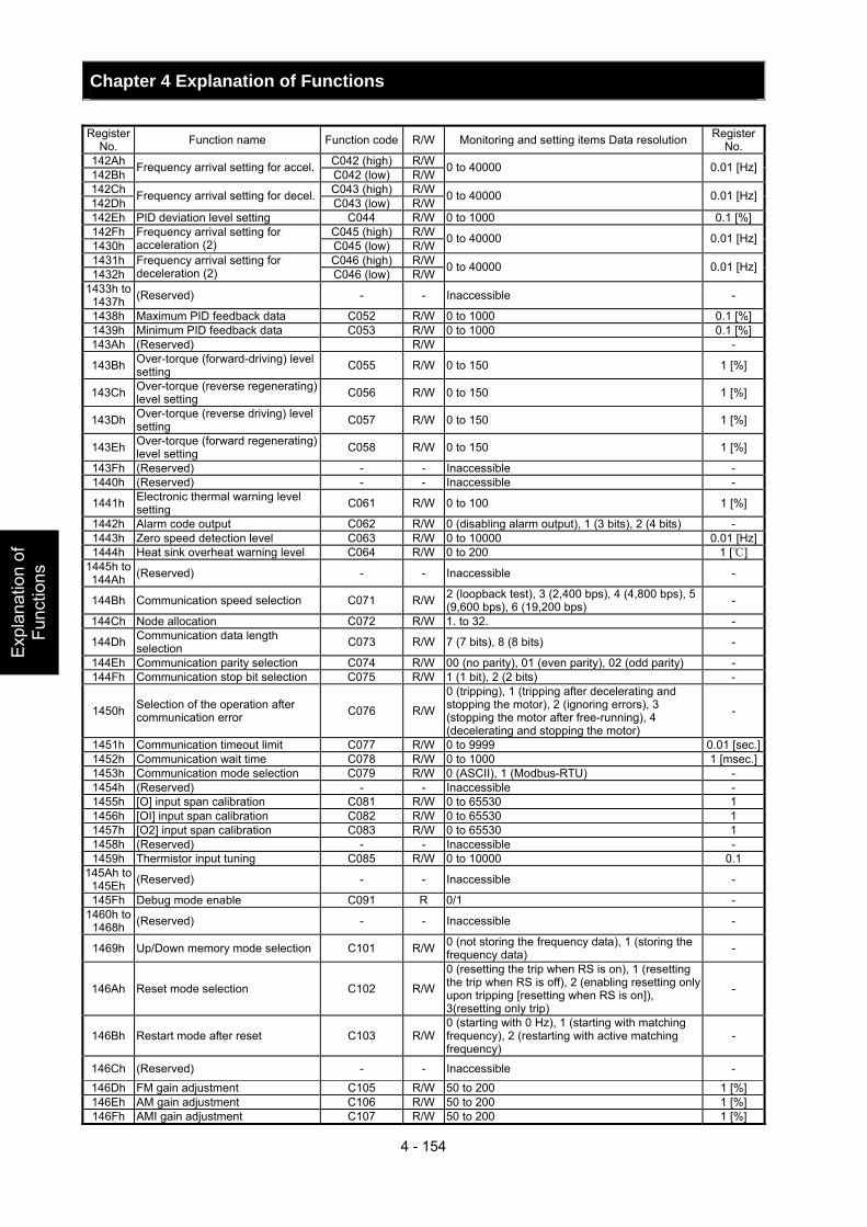
Chapter 4 Explanation of Functions
4 - 154
Exp
lana
tion
of
Func
tions
Register
No. Function name Function code R/W Monitoring and setting items Data resolution Register No.
142Ah C042 (high) R/W142Bh Frequency arrival setting for accel. C042 (low) R/W 0 to 40000 0.01 [Hz]
142Ch C043 (high) R/W142Dh Frequency arrival setting for decel. C043 (low) R/W 0 to 40000 0.01 [Hz]
142Eh PID deviation level setting C044 R/W 0 to 1000 0.1 [%]142Fh C045 (high) R/W1430h
Frequency arrival setting for acceleration (2) C045 (low) R/W 0 to 40000 0.01 [Hz]
1431h C046 (high) R/W1432h
Frequency arrival setting for deceleration (2) C046 (low) R/W 0 to 40000 0.01 [Hz]
1433h to 1437h (Reserved) - - Inaccessible -
1438h Maximum PID feedback data C052 R/W 0 to 1000 0.1 [%]1439h Minimum PID feedback data C053 R/W 0 to 1000 0.1 [%]143Ah (Reserved) R/W -
143Bh Over-torque (forward-driving) level setting C055 R/W 0 to 150 1 [%]
143Ch Over-torque (reverse regenerating) level setting C056 R/W 0 to 150 1 [%]
143Dh Over-torque (reverse driving) level setting C057 R/W 0 to 150 1 [%]
143Eh Over-torque (forward regenerating) level setting C058 R/W 0 to 150 1 [%]
143Fh (Reserved) - - Inaccessible - 1440h (Reserved) - - Inaccessible -
1441h Electronic thermal warning level setting C061 R/W 0 to 100 1 [%]
1442h Alarm code output C062 R/W 0 (disabling alarm output), 1 (3 bits), 2 (4 bits) - 1443h Zero speed detection level C063 R/W 0 to 10000 0.01 [Hz]1444h Heat sink overheat warning level C064 R/W 0 to 200 1 []
1445h to 144Ah (Reserved) - - Inaccessible -
144Bh Communication speed selection C071 R/W 2 (loopback test), 3 (2,400 bps), 4 (4,800 bps), 5 (9,600 bps), 6 (19,200 bps) -
144Ch Node allocation C072 R/W 1. to 32. -
144Dh Communication data length selection C073 R/W 7 (7 bits), 8 (8 bits) -
144Eh Communication parity selection C074 R/W 00 (no parity), 01 (even parity), 02 (odd parity) - 144Fh Communication stop bit selection C075 R/W 1 (1 bit), 2 (2 bits) -
1450h Selection of the operation after communication error C076 R/W
0 (tripping), 1 (tripping after decelerating and stopping the motor), 2 (ignoring errors), 3 (stopping the motor after free-running), 4 (decelerating and stopping the motor)
-
1451h Communication timeout limit C077 R/W 0 to 9999 0.01 [sec.]1452h Communication wait time C078 R/W 0 to 1000 1 [msec.]1453h Communication mode selection C079 R/W 0 (ASCII), 1 (Modbus-RTU) - 1454h (Reserved) - - Inaccessible - 1455h [O] input span calibration C081 R/W 0 to 65530 1 1456h [OI] input span calibration C082 R/W 0 to 65530 1 1457h [O2] input span calibration C083 R/W 0 to 65530 1 1458h (Reserved) - - Inaccessible - 1459h Thermistor input tuning C085 R/W 0 to 10000 0.1
145Ah to 145Eh (Reserved) - - Inaccessible -
145Fh Debug mode enable C091 R 0/1 - 1460h to
1468h (Reserved) - - Inaccessible -
1469h Up/Down memory mode selection C101 R/W 0 (not storing the frequency data), 1 (storing the frequency data) -
146Ah Reset mode selection C102 R/W
0 (resetting the trip when RS is on), 1 (resetting the trip when RS is off), 2 (enabling resetting only upon tripping [resetting when RS is on]), 3(resetting only trip)
-
146Bh Restart mode after reset C103 R/W0 (starting with 0 Hz), 1 (starting with matching frequency), 2 (restarting with active matching frequency)
-
146Ch (Reserved) - - Inaccessible - 146Dh FM gain adjustment C105 R/W 50 to 200 1 [%] 146Eh AM gain adjustment C106 R/W 50 to 200 1 [%] 146Fh AMI gain adjustment C107 R/W 50 to 200 1 [%]
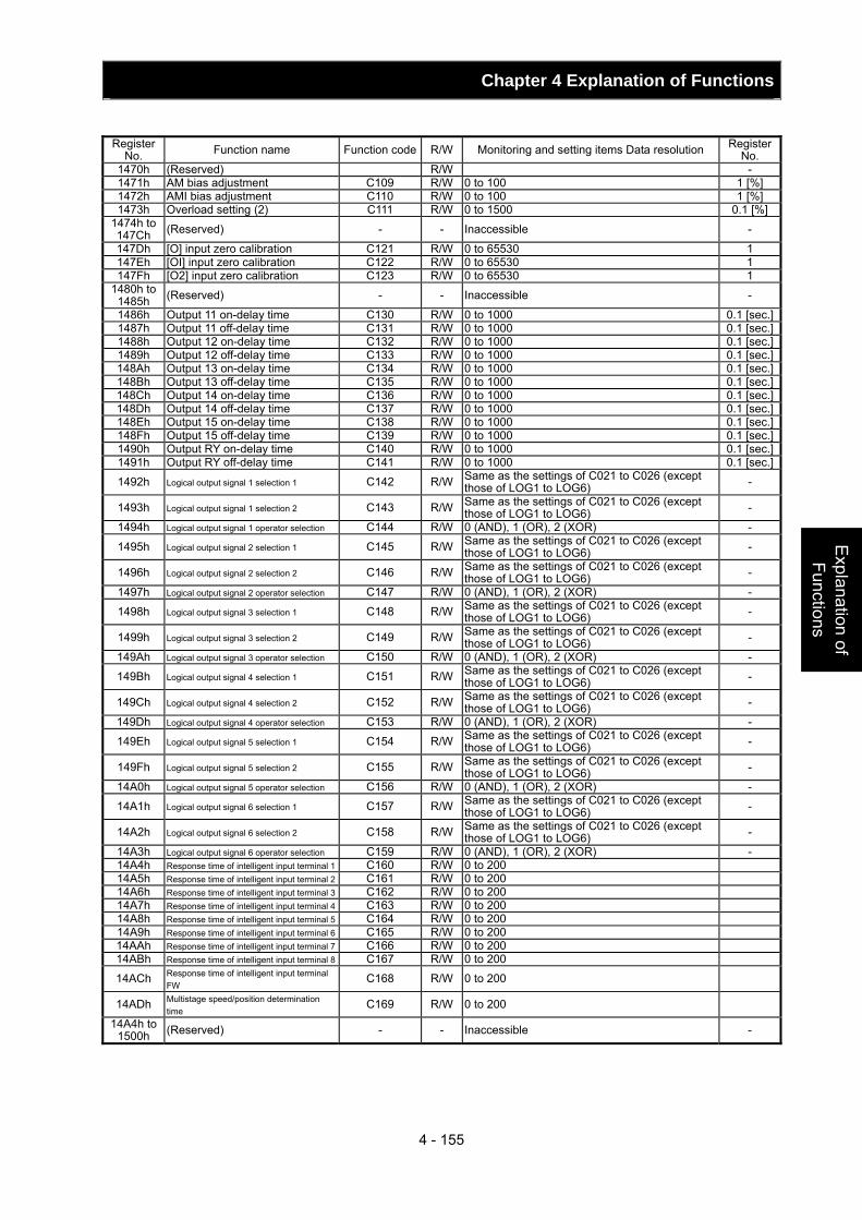
Chapter 4 Explanation of Functions
4 - 155
Explanation of Functions
Register
No. Function name Function code R/W Monitoring and setting items Data resolution Register No.
1470h (Reserved) R/W - 1471h AM bias adjustment C109 R/W 0 to 100 1 [%] 1472h AMI bias adjustment C110 R/W 0 to 100 1 [%] 1473h Overload setting (2) C111 R/W 0 to 1500 0.1 [%]
1474h to 147Ch (Reserved) - - Inaccessible -
147Dh [O] input zero calibration C121 R/W 0 to 65530 1 147Eh [OI] input zero calibration C122 R/W 0 to 65530 1 147Fh [O2] input zero calibration C123 R/W 0 to 65530 1
1480h to 1485h (Reserved) - - Inaccessible -
1486h Output 11 on-delay time C130 R/W 0 to 1000 0.1 [sec.]1487h Output 11 off-delay time C131 R/W 0 to 1000 0.1 [sec.]1488h Output 12 on-delay time C132 R/W 0 to 1000 0.1 [sec.]1489h Output 12 off-delay time C133 R/W 0 to 1000 0.1 [sec.]148Ah Output 13 on-delay time C134 R/W 0 to 1000 0.1 [sec.]148Bh Output 13 off-delay time C135 R/W 0 to 1000 0.1 [sec.]148Ch Output 14 on-delay time C136 R/W 0 to 1000 0.1 [sec.]148Dh Output 14 off-delay time C137 R/W 0 to 1000 0.1 [sec.]148Eh Output 15 on-delay time C138 R/W 0 to 1000 0.1 [sec.]148Fh Output 15 off-delay time C139 R/W 0 to 1000 0.1 [sec.]1490h Output RY on-delay time C140 R/W 0 to 1000 0.1 [sec.]1491h Output RY off-delay time C141 R/W 0 to 1000 0.1 [sec.]
1492h Logical output signal 1 selection 1 C142 R/W Same as the settings of C021 to C026 (except those of LOG1 to LOG6) -
1493h Logical output signal 1 selection 2 C143 R/W Same as the settings of C021 to C026 (except those of LOG1 to LOG6) -
1494h Logical output signal 1 operator selection C144 R/W 0 (AND), 1 (OR), 2 (XOR) -
1495h Logical output signal 2 selection 1 C145 R/W Same as the settings of C021 to C026 (except those of LOG1 to LOG6) -
1496h Logical output signal 2 selection 2 C146 R/W Same as the settings of C021 to C026 (except those of LOG1 to LOG6) -
1497h Logical output signal 2 operator selection C147 R/W 0 (AND), 1 (OR), 2 (XOR) -
1498h Logical output signal 3 selection 1 C148 R/W Same as the settings of C021 to C026 (except those of LOG1 to LOG6) -
1499h Logical output signal 3 selection 2 C149 R/W Same as the settings of C021 to C026 (except those of LOG1 to LOG6) -
149Ah Logical output signal 3 operator selection C150 R/W 0 (AND), 1 (OR), 2 (XOR) -
149Bh Logical output signal 4 selection 1 C151 R/W Same as the settings of C021 to C026 (except those of LOG1 to LOG6) -
149Ch Logical output signal 4 selection 2 C152 R/W Same as the settings of C021 to C026 (except those of LOG1 to LOG6) -
149Dh Logical output signal 4 operator selection C153 R/W 0 (AND), 1 (OR), 2 (XOR) -
149Eh Logical output signal 5 selection 1 C154 R/W Same as the settings of C021 to C026 (except those of LOG1 to LOG6) -
149Fh Logical output signal 5 selection 2 C155 R/W Same as the settings of C021 to C026 (except those of LOG1 to LOG6) -
14A0h Logical output signal 5 operator selection C156 R/W 0 (AND), 1 (OR), 2 (XOR) -
14A1h Logical output signal 6 selection 1 C157 R/W Same as the settings of C021 to C026 (except those of LOG1 to LOG6) -
14A2h Logical output signal 6 selection 2 C158 R/W Same as the settings of C021 to C026 (except those of LOG1 to LOG6) -
14A3h Logical output signal 6 operator selection C159 R/W 0 (AND), 1 (OR), 2 (XOR) - 14A4h Response time of intelligent input terminal 1 C160 R/W 0 to 200 14A5h Response time of intelligent input terminal 2 C161 R/W 0 to 200 14A6h Response time of intelligent input terminal 3 C162 R/W 0 to 200 14A7h Response time of intelligent input terminal 4 C163 R/W 0 to 200 14A8h Response time of intelligent input terminal 5 C164 R/W 0 to 200 14A9h Response time of intelligent input terminal 6 C165 R/W 0 to 200 14AAh Response time of intelligent input terminal 7 C166 R/W 0 to 200 14ABh Response time of intelligent input terminal 8 C167 R/W 0 to 200
14ACh Response time of intelligent input terminal FW
C168 R/W 0 to 200
14ADh Multistage speed/position determination time
C169 R/W 0 to 200
14A4h to 1500h (Reserved) - - Inaccessible -
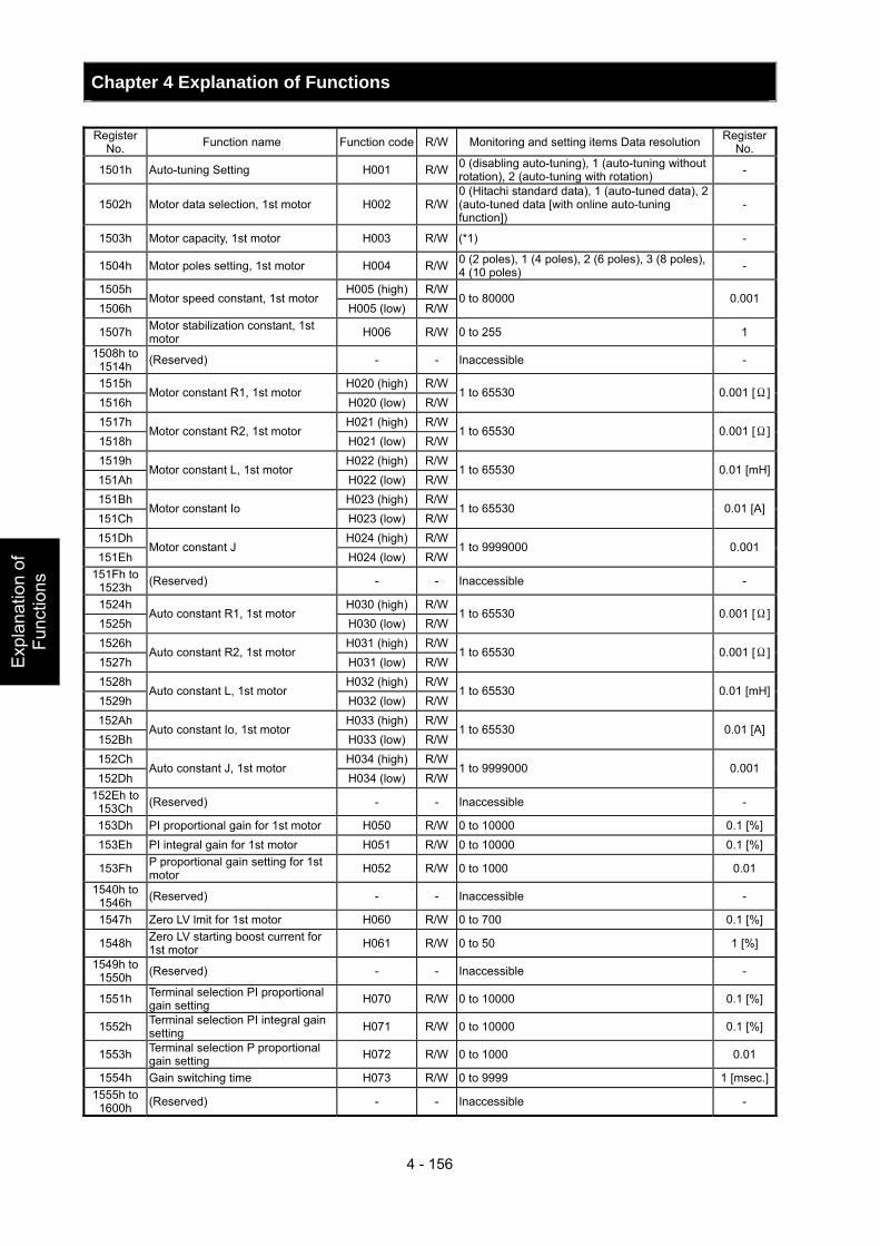
Chapter 4 Explanation of Functions
4 - 156
Exp
lana
tion
of
Func
tions
Register
No. Function name Function code R/W Monitoring and setting items Data resolution Register No.
1501h Auto-tuning Setting H001 R/W 0 (disabling auto-tuning), 1 (auto-tuning without rotation), 2 (auto-tuning with rotation) -
1502h Motor data selection, 1st motor H002 R/W0 (Hitachi standard data), 1 (auto-tuned data), 2 (auto-tuned data [with online auto-tuning function])
-
1503h Motor capacity, 1st motor H003 R/W (*1) -
1504h Motor poles setting, 1st motor H004 R/W 0 (2 poles), 1 (4 poles), 2 (6 poles), 3 (8 poles), 4 (10 poles) -
1505h H005 (high) R/W1506h
Motor speed constant, 1st motor H005 (low) R/W
0 to 80000 0.001
1507h Motor stabilization constant, 1st motor H006 R/W 0 to 255 1
1508h to 1514h (Reserved) - - Inaccessible -
1515h H020 (high) R/W1516h
Motor constant R1, 1st motor H020 (low) R/W
1 to 65530 0.001 [Ω]
1517h H021 (high) R/W1518h
Motor constant R2, 1st motor H021 (low) R/W
1 to 65530 0.001 [Ω]
1519h H022 (high) R/W151Ah
Motor constant L, 1st motor H022 (low) R/W
1 to 65530 0.01 [mH]
151Bh H023 (high) R/W151Ch
Motor constant Io H023 (low) R/W
1 to 65530 0.01 [A]
151Dh H024 (high) R/W151Eh
Motor constant J H024 (low) R/W
1 to 9999000 0.001
151Fh to 1523h (Reserved) - - Inaccessible -
1524h H030 (high) R/W1525h
Auto constant R1, 1st motor H030 (low) R/W
1 to 65530 0.001 [Ω]
1526h H031 (high) R/W1527h
Auto constant R2, 1st motor H031 (low) R/W
1 to 65530 0.001 [Ω]
1528h H032 (high) R/W1529h
Auto constant L, 1st motor H032 (low) R/W
1 to 65530 0.01 [mH]
152Ah H033 (high) R/W152Bh
Auto constant Io, 1st motor H033 (low) R/W
1 to 65530 0.01 [A]
152Ch H034 (high) R/W152Dh
Auto constant J, 1st motor H034 (low) R/W
1 to 9999000 0.001
152Eh to 153Ch (Reserved) - - Inaccessible -
153Dh PI proportional gain for 1st motor H050 R/W 0 to 10000 0.1 [%]153Eh PI integral gain for 1st motor H051 R/W 0 to 10000 0.1 [%]
153Fh P proportional gain setting for 1st motor H052 R/W 0 to 1000 0.01
1540h to 1546h (Reserved) - - Inaccessible -
1547h Zero LV lmit for 1st motor H060 R/W 0 to 700 0.1 [%]
1548h Zero LV starting boost current for 1st motor H061 R/W 0 to 50 1 [%]
1549h to 1550h (Reserved) - - Inaccessible -
1551h Terminal selection PI proportional gain setting H070 R/W 0 to 10000 0.1 [%]
1552h Terminal selection PI integral gain setting H071 R/W 0 to 10000 0.1 [%]
1553h Terminal selection P proportional gain setting H072 R/W 0 to 1000 0.01
1554h Gain switching time H073 R/W 0 to 9999 1 [msec.]1555h to
1600h (Reserved) - - Inaccessible -
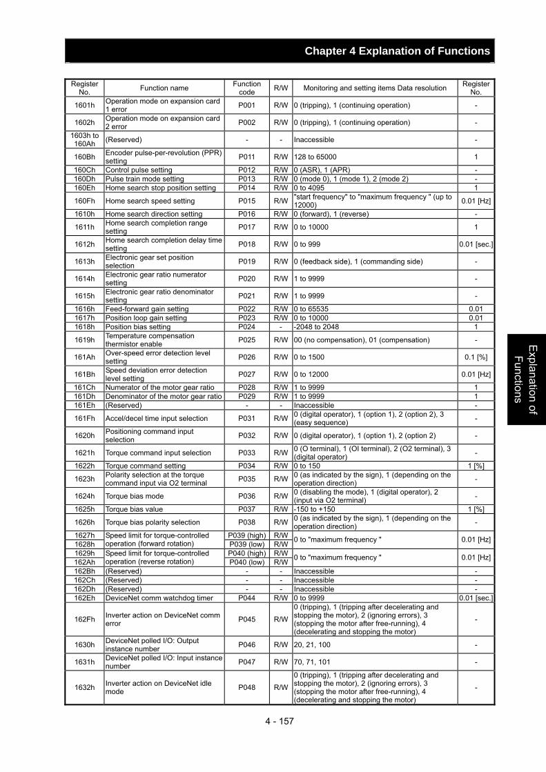
Chapter 4 Explanation of Functions
4 - 157
Explanation of Functions
Register
No. Function name Function code R/W Monitoring and setting items Data resolution Register
No.
1601h Operation mode on expansion card 1 error P001 R/W 0 (tripping), 1 (continuing operation) -
1602h Operation mode on expansion card 2 error P002 R/W 0 (tripping), 1 (continuing operation) -
1603h to 160Ah (Reserved) - - Inaccessible -
160Bh Encoder pulse-per-revolution (PPR) setting P011 R/W 128 to 65000 1
160Ch Control pulse setting P012 R/W 0 (ASR), 1 (APR) - 160Dh Pulse train mode setting P013 R/W 0 (mode 0), 1 (mode 1), 2 (mode 2) - 160Eh Home search stop position setting P014 R/W 0 to 4095 1
160Fh Home search speed setting P015 R/W "start frequency" to "maximum frequency " (up to 12000) 0.01 [Hz]
1610h Home search direction setting P016 R/W 0 (forward), 1 (reverse) -
1611h Home search completion range setting P017 R/W 0 to 10000 1
1612h Home search completion delay time setting P018 R/W 0 to 999 0.01 [sec.]
1613h Electronic gear set position selection P019 R/W 0 (feedback side), 1 (commanding side) -
1614h Electronic gear ratio numerator setting P020 R/W 1 to 9999 -
1615h Electronic gear ratio denominator setting P021 R/W 1 to 9999 -
1616h Feed-forward gain setting P022 R/W 0 to 65535 0.01 1617h Position loop gain setting P023 R/W 0 to 10000 0.01 1618h Position bias setting P024 - -2048 to 2048 1
1619h Temperature compensation thermistor enable P025 R/W 00 (no compensation), 01 (compensation) -
161Ah Over-speed error detection level setting P026 R/W 0 to 1500 0.1 [%]
161Bh Speed deviation error detection level setting P027 R/W 0 to 12000 0.01 [Hz]
161Ch Numerator of the motor gear ratio P028 R/W 1 to 9999 1 161Dh Denominator of the motor gear ratio P029 R/W 1 to 9999 1 161Eh (Reserved) - - Inaccessible -
161Fh Accel/decel time input selection P031 R/W 0 (digital operator), 1 (option 1), 2 (option 2), 3 (easy sequence) -
1620h Positioning command input selection P032 R/W 0 (digital operator), 1 (option 1), 2 (option 2) -
1621h Torque command input selection P033 R/W 0 (O terminal), 1 (OI terminal), 2 (O2 terminal), 3 (digital operator) -
1622h Torque command setting P034 R/W 0 to 150 1 [%]
1623h Polarity selection at the torque command input via O2 terminal P035 R/W 0 (as indicated by the sign), 1 (depending on the
operation direction) -
1624h Torque bias mode P036 R/W 0 (disabling the mode), 1 (digital operator), 2 (input via O2 terminal) -
1625h Torque bias value P037 R/W -150 to +150 1 [%]
1626h Torque bias polarity selection P038 R/W 0 (as indicated by the sign), 1 (depending on the operation direction) -
1627h P039 (high) R/W1628h
Speed limit for torque-controlled operation (forward rotation) P039 (low) R/W 0 to "maximum frequency " 0.01 [Hz]
1629h P040 (high) R/W162Ah
Speed limit for torque-controlled operation (reverse rotation) P040 (low) R/W 0 to "maximum frequency " 0.01 [Hz]
162Bh (Reserved) - - Inaccessible - 162Ch (Reserved) - - Inaccessible - 162Dh (Reserved) - - Inaccessible - 162Eh DeviceNet comm watchdog timer P044 R/W 0 to 9999 0.01 [sec.]
162Fh Inverter action on DeviceNet comm error P045 R/W
0 (tripping), 1 (tripping after decelerating and stopping the motor), 2 (ignoring errors), 3 (stopping the motor after free-running), 4 (decelerating and stopping the motor)
-
1630h DeviceNet polled I/O: Output instance number P046 R/W 20, 21, 100 -
1631h DeviceNet polled I/O: Input instance number P047 R/W 70, 71, 101 -
1632h Inverter action on DeviceNet idle mode P048 R/W
0 (tripping), 1 (tripping after decelerating and stopping the motor), 2 (ignoring errors), 3 (stopping the motor after free-running), 4 (decelerating and stopping the motor)
-
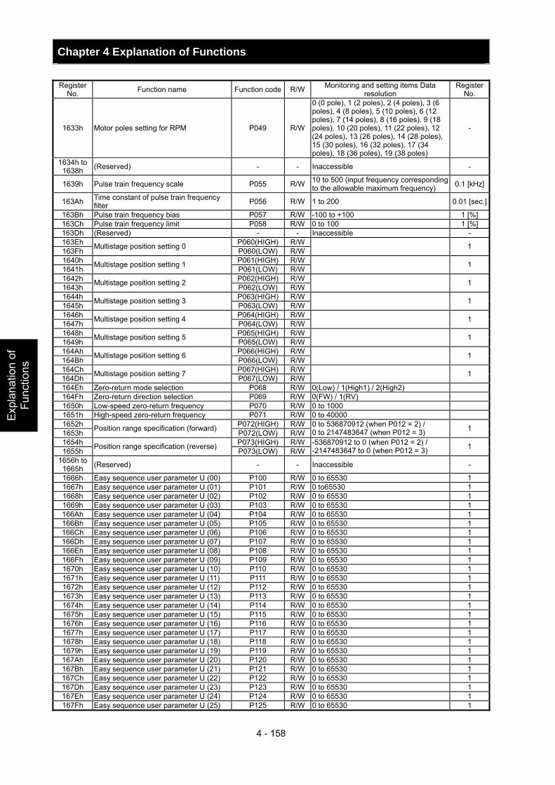
Chapter 4 Explanation of Functions
4 - 158
Exp
lana
tion
of
Func
tions
Register
No. Function name Function code R/W Monitoring and setting items Data resolution
Register No.
1633h Motor poles setting for RPM P049 R/W
0 (0 pole), 1 (2 poles), 2 (4 poles), 3 (6 poles), 4 (8 poles), 5 (10 poles), 6 (12 poles), 7 (14 poles), 8 (16 poles), 9 (18 poles), 10 (20 poles), 11 (22 poles), 12 (24 poles), 13 (26 poles), 14 (28 poles), 15 (30 poles), 16 (32 poles), 17 (34 poles), 18 (36 poles), 19 (38 poles)
-
1634h to 1638h (Reserved) - - Inaccessible -
1639h Pulse train frequency scale P055 R/W 10 to 500 (input frequency corresponding to the allowable maximum frequency) 0.1 [kHz]
163Ah Time constant of pulse train frequency filter P056 R/W 1 to 200 0.01 [sec.]
163Bh Pulse train frequency bias P057 R/W -100 to +100 1 [%] 163Ch Pulse train frequency limit P058 R/W 0 to 100 1 [%] 163Dh (Reserved) - - Inaccessible - 163Eh P060(HIGH) R/W163Fh Multistage position setting 0 P060(LOW) R/W 1
1640h P061(HIGH) R/W1641h Multistage position setting 1 P061(LOW) R/W 1
1642h P062(HIGH) R/W1643h Multistage position setting 2 P062(LOW) R/W 1
1644h P063(HIGH) R/W1645h Multistage position setting 3 P063(LOW) R/W 1
1646h P064(HIGH) R/W1647h Multistage position setting 4 P064(LOW) R/W 1
1648h P065(HIGH) R/W1649h Multistage position setting 5 P065(LOW) R/W 1
164Ah P066(HIGH) R/W164Bh Multistage position setting 6 P066(LOW) R/W 1
164Ch P067(HIGH) R/W164Dh Multistage position setting 7 P067(LOW) R/W 1
164Eh Zero-return mode selection P068 R/W 0(Low) / 1(High1) / 2(High2) 164Fh Zero-return direction selection P069 R/W 0(FW) / 1(RV) 1650h Low-speed zero-return frequency P070 R/W 0 to 1000 1651h High-speed zero-return frequency P071 R/W 0 to 40000 1652h P072(HIGH) R/W1653h Position range specification (forward) P072(LOW) R/W
0 to 536870912 (when P012 = 2) / 0 to 2147483647 (when P012 = 3) 1
1654h P073(HIGH) R/W1655h Position range specification (reverse) P073(LOW) R/W
-536870912 to 0 (when P012 = 2) / -2147483647 to 0 (when P012 = 3) 1
1656h to 1665h (Reserved) - - Inaccessible -
1666h Easy sequence user parameter U (00) P100 R/W 0 to 65530 1 1667h Easy sequence user parameter U (01) P101 R/W 0 to65530 1 1668h Easy sequence user parameter U (02) P102 R/W 0 to 65530 1 1669h Easy sequence user parameter U (03) P103 R/W 0 to 65530 1 166Ah Easy sequence user parameter U (04) P104 R/W 0 to 65530 1 166Bh Easy sequence user parameter U (05) P105 R/W 0 to 65530 1 166Ch Easy sequence user parameter U (06) P106 R/W 0 to 65530 1 166Dh Easy sequence user parameter U (07) P107 R/W 0 to 65530 1 166Eh Easy sequence user parameter U (08) P108 R/W 0 to 65530 1 166Fh Easy sequence user parameter U (09) P109 R/W 0 to 65530 1 1670h Easy sequence user parameter U (10) P110 R/W 0 to 65530 1 1671h Easy sequence user parameter U (11) P111 R/W 0 to 65530 1 1672h Easy sequence user parameter U (12) P112 R/W 0 to 65530 1 1673h Easy sequence user parameter U (13) P113 R/W 0 to 65530 1 1674h Easy sequence user parameter U (14) P114 R/W 0 to 65530 1 1675h Easy sequence user parameter U (15) P115 R/W 0 to 65530 1 1676h Easy sequence user parameter U (16) P116 R/W 0 to 65530 1 1677h Easy sequence user parameter U (17) P117 R/W 0 to 65530 1 1678h Easy sequence user parameter U (18) P118 R/W 0 to 65530 1 1679h Easy sequence user parameter U (19) P119 R/W 0 to 65530 1 167Ah Easy sequence user parameter U (20) P120 R/W 0 to 65530 1 167Bh Easy sequence user parameter U (21) P121 R/W 0 to 65530 1 167Ch Easy sequence user parameter U (22) P122 R/W 0 to 65530 1 167Dh Easy sequence user parameter U (23) P123 R/W 0 to 65530 1 167Eh Easy sequence user parameter U (24) P124 R/W 0 to 65530 1 167Fh Easy sequence user parameter U (25) P125 R/W 0 to 65530 1
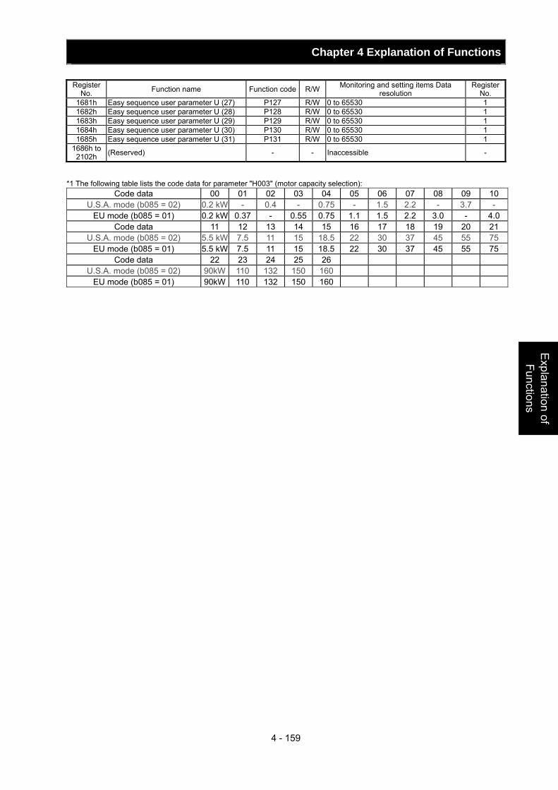
Chapter 4 Explanation of Functions
4 - 159
Explanation of Functions
Register No. Function name Function code R/W Monitoring and setting items Data
resolution Register
No. 1681h Easy sequence user parameter U (27) P127 R/W 0 to 65530 1 1682h Easy sequence user parameter U (28) P128 R/W 0 to 65530 1 1683h Easy sequence user parameter U (29) P129 R/W 0 to 65530 1 1684h Easy sequence user parameter U (30) P130 R/W 0 to 65530 1 1685h Easy sequence user parameter U (31) P131 R/W 0 to 65530 1
1686h to 2102h (Reserved) - - Inaccessible -
*1 The following table lists the code data for parameter "H003" (motor capacity selection):
Code data 00 01 02 03 04 05 06 07 08 09 10 U.S.A. mode (b085 = 02) 0.2 kW - 0.4 - 0.75 - 1.5 2.2 - 3.7 -
EU mode (b085 = 01) 0.2 kW 0.37 - 0.55 0.75 1.1 1.5 2.2 3.0 - 4.0Code data 11 12 13 14 15 16 17 18 19 20 21
U.S.A. mode (b085 = 02) 5.5 kW 7.5 11 15 18.5 22 30 37 45 55 75 EU mode (b085 = 01) 5.5 kW 7.5 11 15 18.5 22 30 37 45 55 75
Code data 22 23 24 25 26 U.S.A. mode (b085 = 02) 90kW 110 132 150 160
EU mode (b085 = 01) 90kW 110 132 150 160
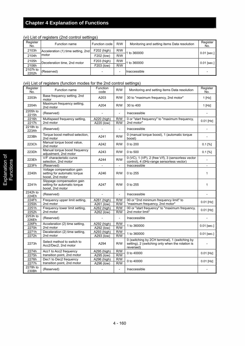
Chapter 4 Explanation of Functions
4 - 160
Exp
lana
tion
of
Func
tions
(vi) List of registers (2nd control settings) Register
No. Function name Function code R/W Monitoring and setting items Data resolution Register No.
2103h F202 (high) R/W2104h
Acceleration (1) time setting, 2nd motor F202 (low) R/W
1 to 360000 0.01 [sec.]
2105h F203 (high) R/W2106h
Deceleration time, 2nd motor F203 (low) R/W
1 to 360000 0.01 [sec.]
2107h to 2202h (Reserved) - - Inaccessible -
(vii) List of registers (function modes for the 2nd control settings)
Register No. Function name Function
code R/W Monitoring and setting items Data resolution Register No.
2203h Base frequency setting, 2nd motor A203 R/W 30 to "maximum frequency, 2nd motor" 1 [Hz]
2204h Maximum frequency setting, 2nd motor A204 R/W 30 to 400 1 [Hz]
2205h to 2215h (Reserved) - - Inaccessible -
2216h A220 (high) R/W2217h
Multispeed frequency setting, 2nd motor A220 (low) R/W
0 or "start frequency" to "maximum frequency, 2nd motor" 0.01 [Hz]
2218h to 223Ah (Reserved) - - Inaccessible -
223Bh Torque boost method selection, 2nd motor A241 R/W 0 (manual torque boost), 1 (automatic torque
boost) -
223Ch Manual torque boost value, 2nd motor A242 R/W 0 to 200 0.1 [%]
223Dh Manual torque boost frequency adjustment, 2nd motor A243 R/W 0 to 500 0.1 [%]
223Eh V/F characteristic curve selection, 2nd motor A244 R/W 0 (VC), 1 (VP), 2 (free V/f), 3 (sensorless vector
control), 4 (0Hz-range sensorless vector) -
223Fh (Reserved) - - Inaccessible -
2240h Voltage compensation gain setting for automatic torque boost, 2nd motor
A246 R/W 0 to 255 1
2241h Slippage compensation gain setting for automatic torque boost, 2nd motor
A247 R/W 0 to 255 1
2242h to 224Eh (Reserved) - - Inaccessible -
224Fh A261 (high) R/W2250h
Frequency upper limit setting, 2nd motor A261 (low) R/W
00 or "2nd minimum frequency limit" to "maximum frequency, 2nd motor" 0.01 [Hz]
2251h A262 (high) R/W2252h
Frequency lower limit setting, 2nd motor A262 (low) R/W
00 or "start frequency" to "maximum frequency, 2nd motor limit" 0.01 [Hz]
2253h to 226Eh (Reserved) - - Inaccessible -
226Fh A292 (high) R/W2270h
Acceleration (2) time setting, 2nd motor A292 (low) R/W 1 to 360000 0.01 [sec.]
2271h A293 (high) R/W2272h
Deceleration (2) time setting, 2nd motor A293 (low) R/W 1 to 360000 0.01 [sec.]
2273h Select method to switch to Acc2/Dec2, 2nd motor A294 R/W
0 (switching by 2CH terminal), 1 (switching by setting), 2 (switching only when the rotation is reversed)
-
2274h A295 (high) R/W2275h
Acc1 to Acc2 frequency transition point, 2nd motor A295 (low) R/W 0 to 40000 0.01 [Hz]
2276h A296 (high) R/W2277h
Dec1 to Dec2 frequency transition point, 2nd motor A296 (low) R/W 0 to 40000 0.01 [Hz]
2278h to 230Bh (Reserved) - - Inaccessible -
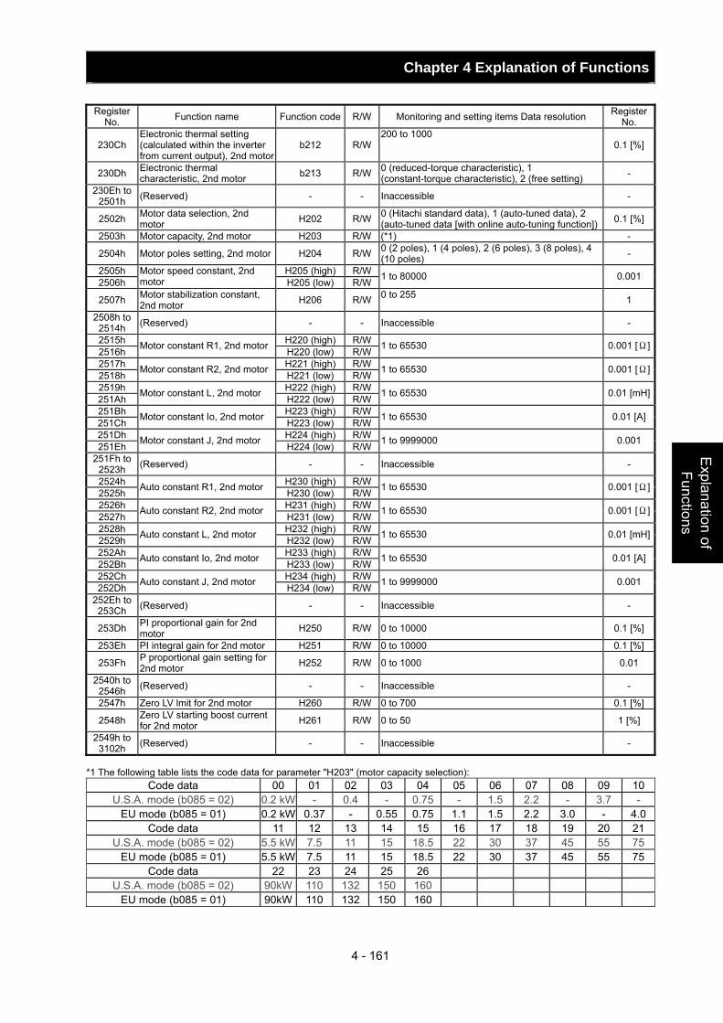
Chapter 4 Explanation of Functions
4 - 161
Explanation of Functions
Register
No. Function name Function code R/W Monitoring and setting items Data resolution Register No.
230Ch Electronic thermal setting (calculated within the inverter from current output), 2nd motor
b212 R/W200 to 1000
0.1 [%]
230Dh Electronic thermal characteristic, 2nd motor b213 R/W 0 (reduced-torque characteristic), 1
(constant-torque characteristic), 2 (free setting) -
230Eh to 2501h (Reserved) - - Inaccessible -
2502h Motor data selection, 2nd motor H202 R/W 0 (Hitachi standard data), 1 (auto-tuned data), 2
(auto-tuned data [with online auto-tuning function]) 0.1 [%]
2503h Motor capacity, 2nd motor H203 R/W (*1) -
2504h Motor poles setting, 2nd motor H204 R/W 0 (2 poles), 1 (4 poles), 2 (6 poles), 3 (8 poles), 4 (10 poles) -
2505h H205 (high) R/W2506h
Motor speed constant, 2nd motor H205 (low) R/W 1 to 80000 0.001
2507h Motor stabilization constant, 2nd motor H206 R/W 0 to 255 1
2508h to 2514h (Reserved) - - Inaccessible -
2515h H220 (high) R/W2516h Motor constant R1, 2nd motor H220 (low) R/W 1 to 65530 0.001 [Ω]
2517h H221 (high) R/W2518h Motor constant R2, 2nd motor H221 (low) R/W 1 to 65530 0.001 [Ω]
2519h H222 (high) R/W251Ah Motor constant L, 2nd motor H222 (low) R/W 1 to 65530 0.01 [mH]
251Bh H223 (high) R/W251Ch Motor constant Io, 2nd motor H223 (low) R/W 1 to 65530 0.01 [A]
251Dh H224 (high) R/W251Eh Motor constant J, 2nd motor H224 (low) R/W 1 to 9999000 0.001
251Fh to 2523h (Reserved) - - Inaccessible -
2524h H230 (high) R/W2525h Auto constant R1, 2nd motor H230 (low) R/W 1 to 65530 0.001 [Ω]
2526h H231 (high) R/W2527h Auto constant R2, 2nd motor H231 (low) R/W 1 to 65530 0.001 [Ω]
2528h H232 (high) R/W2529h Auto constant L, 2nd motor H232 (low) R/W 1 to 65530 0.01 [mH]
252Ah H233 (high) R/W252Bh Auto constant Io, 2nd motor H233 (low) R/W 1 to 65530 0.01 [A]
252Ch H234 (high) R/W252Dh Auto constant J, 2nd motor H234 (low) R/W 1 to 9999000 0.001
252Eh to 253Ch (Reserved) - - Inaccessible -
253Dh PI proportional gain for 2nd motor H250 R/W 0 to 10000 0.1 [%]
253Eh PI integral gain for 2nd motor H251 R/W 0 to 10000 0.1 [%]
253Fh P proportional gain setting for 2nd motor H252 R/W 0 to 1000 0.01
2540h to 2546h (Reserved) - - Inaccessible -
2547h Zero LV lmit for 2nd motor H260 R/W 0 to 700 0.1 [%]
2548h Zero LV starting boost current for 2nd motor H261 R/W 0 to 50 1 [%]
2549h to 3102h (Reserved) - - Inaccessible -
*1 The following table lists the code data for parameter "H203" (motor capacity selection):
Code data 00 01 02 03 04 05 06 07 08 09 10U.S.A. mode (b085 = 02) 0.2 kW - 0.4 - 0.75 - 1.5 2.2 - 3.7 -
EU mode (b085 = 01) 0.2 kW 0.37 - 0.55 0.75 1.1 1.5 2.2 3.0 - 4.0Code data 11 12 13 14 15 16 17 18 19 20 21
U.S.A. mode (b085 = 02) 5.5 kW 7.5 11 15 18.5 22 30 37 45 55 75EU mode (b085 = 01) 5.5 kW 7.5 11 15 18.5 22 30 37 45 55 75
Code data 22 23 24 25 26 U.S.A. mode (b085 = 02) 90kW 110 132 150 160
EU mode (b085 = 01) 90kW 110 132 150 160

Chapter 4 Explanation of Functions
4 - 162
Exp
lana
tion
of
Func
tions
(viii) List of registers (3rd control settings) Register
No. Function name Function code R/W Monitoring and setting items Data resolution Register No.
3103h F302 (high) R/W3104h
Acceleration (1) time setting, 3rd motor F302 (low) R/W 1 to 360000 0.01 [sec.]
3105h F303 (high) R/W3106h
Deceleration (1) time setting, 3rd motor F303 (low) R/W 1 to 360000 0.01 [sec.]
3107h to 3202h (Reserved) - - Inaccessible -
(ix) List of registers (3rd control setting)
Register No. Function name Function code R/W Monitoring and setting items Data resolution Register
No.
3203h Base frequency setting, 3rd motor A303 R/W 30 to "maximum frequency, 3rd motor" 1 [Hz]
3204h Maximum frequency setting, 3rd motor A304 R/W 30 to 400 1 [Hz]
3205h to 3215h (Reserved) - - Inaccessible -
3216h A320 (high) R/W3217h
Multispeed frequency setting, 3rd motor A320 (low) R/W
0 or "start frequency" to "maximum frequency, 3rd motor" 0.01 [Hz]
3218h to 323Bh (Reserved) - - Inaccessible -
323Ch Manual torque boost value, 3rd motor A342 R/W 0 to 200 0.1 [%]
323Dh Manual torque boost frequency adjustment, 3rd motor A343 R/W 0 to 500 0.1 [%]
323Eh V/F characteristic curve selection, 3rd motor A344 R/W 0 (VC), 1(VP) -
323Fh to 326Ch (Reserved) - - Inaccessible -
326Dh A392 (high) R/W326Eh
Acceleration (2) time setting, 3rd motor A392 (low) R/W 1 to 360000 0.01 [sec.]
326Fh A393 (high) R/W3270h
Deceleration (2) time setting, 3rd motor A393 (low) R/W 1 to 360000 0.01 [sec.]
3271h to 330B (Reserved) - - Inaccessible -
330Ch Electronic thermal setting (calculated within the inverter from current output), 3rd motor
b312 R/W 200 to 1000 0.1 [%]
330Dh Electronic thermal characteristic, 3rd motor b313 R/W 0 (reduced-torque characteristic), 1
(constant-torque characteristic), 2 (free setting) -
330Eh to 3506h (Reserved) - - Inaccessible -
3507h Motor stabilization constant, 3rd motor H306 R/W 0 to 255 1
3508h to (Reserved) - - Inaccessible -
Chapter 5 Error Codes This chapter describes the error codes of the inverter, error indications by the functions, and troubleshooting methods.
5.1 Error Codes and Troubleshooting ···················· 5 - 1 5.2 Warning Codes················································· 5 – 10
Error C
odes


Chapter 5 Error Codes
5 - 1
Error C
odes
OC.Drive
OC.Decel
OC.Accel
Over.C
Over.L
OL.BRD
Over.V
EEPROM
5.1 Error Codes and Troubleshooting
5.1.1 Error Codes
Name Description Display on digital operator
Display on remote operator Troubleshooting and corrective action Reference
page
During constant-
speed operation
Check whether the load has fluctuated sharply.(Eliminate the load fluctuation.)
Check for the short circuit of output connections.
(Check the output cables.)Check for the ground fault.
(Check the output cables and motor.)
-
During deceleration
Check whether the inverter has decelerated the motor quickly.
(Increase the deceleration time.)
4-10 4-31
During acceleration
Check whether the inverter has accelerated the motor quickly.
(Increase the acceleration time.)Check whether the motor has been locked.
(Check the motor and wiring.)Check whether the torque boost current has been set too high.
(Reduce the boost current.)
4-10 4-31
Overcurrent protection
If the motor is constrained or suddenly accelerated or decelerated, a high current will flow in the inverter and the inverter may fail. To avoid this problem, the inverter shuts off its output and displays the error code shown on the right when it detects a current higher than a specified level. This protective function uses a DC current detector (CT) to detect overcurrent. When a current as high as about 160% of the inverter's rated output current is detected, the protective circuit operates and the inverter trips.
Others
Check whether the DC braking force is too high.(Reduce the braking force.)
Check whether the current detector (CT) is normal.
(Replace or repair the CT.)
4-21
Overload protection
(*1)
This protective function monitors the inverter output current, and shuts off the inverter output and displays the error code shown on the right when the internal electronic thermal protection circuit detects a motor overload. If the error occurs, the inverter will trip according to the setting of the electronic thermal function.
Check whether the motor load is too high. (Reduce the load factor.)
Check whether the thermal level is appropriate.(Adjust the level appropriately.)
Note: The electronic thermal protection is easily triggered when the output frequency is 5 Hz or less. If the moment of inertia of the load is large, this protective function may operate when the inverter accelerates the motor and the acceleration may be disabled. If this problem occurs, increase the torque boost current or adjust other settings as needed.
4-38
Braking resistor overload
protection
When the BRD operation rate exceeds the setting of "b090", this protective function shuts off the inverter output and displays the error code shown on the right.
Check whether the inverter has decreased the motor quickly.
(Increase the deceleration time.)Check whether the operation cycle is too short.
(Prolong the operation cycle.)Check whether the set BRD operation rate is too low.
(Adjust the setting to an appropriate level.)Note: confirm the maximum allowable capacity of the resistor.
4-10 4-45
Overvoltage protection
If the DC voltage across the P and N terminals rises too high, an inverter failure may result. To avoid this problem, this protective function shuts off the inverter output and displays the error code shown on the right when the DC voltage across the P and N terminals exceeds a specified level because of an increase in the energy regenerated by the motor or the input voltage (during operation). The inverter will trip if the DC voltage across the P and N terminals exceeds about 400 VDC (in case of the 200 V class models) or about 800 VDC (in case of the 400 V class models).
Check whether the inverter has decreased the motor quickly.
(Increase the deceleration time.)Check for a ground fault.
(Check the output cables and motor.)Check whether the motor has been rotated by the action of the load.
(Reduce the regenerative energy.)
-
EEPROM error
(*2) (*3)
When an internal-EEPROM is caused by external noise or an abnormal temperature rise, the inverter shuts off its output and displays the error code shown on the right. Note: An EEPROM error may result in a CPU error.
Check for the noise sources located near the inverter.
(Remove noise sources.)Check whether the cooling efficiency has deteriorated. (Check the heat sink for clogging, and clean it.)
(Replace the cooling fan.)
-
*1 The inverter will not accept any reset command within about 10 seconds after tripping (i.e., after the protective function operates).
*2 The inverter will not accept any reset command after an EEPROM error occurs with error code displayed. Turn off the inverter power once. If error code "E08" is displayed when the inverter power is turned on subsequently, the internal memory device may have failed or parameters may have not been stored correctly. In such cases, initialize the inverter, and then re-set the parameters.
*3 The inverter will not accept reset commands input via the RS terminal or entered by the STOP/RESET key. Therefore, turn off the inverter power.
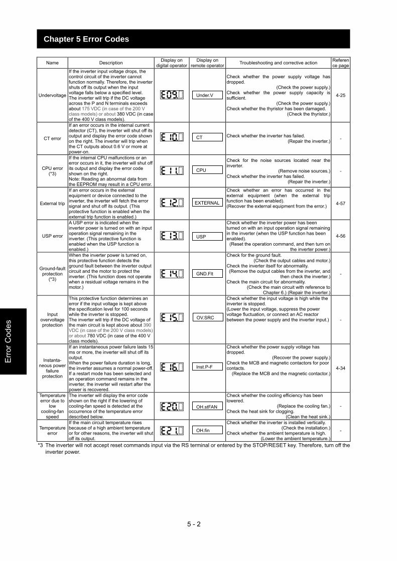
5 - 2
Err
or C
odes
Chapter 5 Error Codes
Under.V
CT
CPU
EXTERNAL
USP
GND.Flt
OV.SRC
Inst.P-F
OH.stFAN
OH.fin
Name Description Display on
digital operatorDisplay on
remote operator Troubleshooting and corrective action Reference page
Undervoltage
If the inverter input voltage drops, the control circuit of the inverter cannot function normally. Therefore, the inverter shuts off its output when the input voltage falls below a specified level. The inverter will trip if the DC voltage across the P and N terminals exceeds about 175 VDC (in case of the 200 V class models) or about 380 VDC (in case of the 400 V class models).
Check whether the power supply voltage has dropped.
(Check the power supply.)Check whether the power supply capacity is sufficient.
(Check the power supply.)Check whether the thyristor has been damaged.
(Check the thyristor.)
4-25
CT error
If an error occurs in the internal current detector (CT), the inverter will shut off its output and display the error code shown on the right. The inverter will trip when the CT outputs about 0.6 V or more at power-on.
Check whether the inverter has failed. (Repair the inverter.) -
CPU error (*3)
If the internal CPU malfunctions or an error occurs in it, the inverter will shut off its output and display the error code shown on the right. Note: Reading an abnormal data from the EEPROM may result in a CPU error.
Check for the noise sources located near the inverter.
(Remove noise sources.)Check whether the inverter has failed.
(Repair the inverter.)
-
External trip
If an error occurs in the external equipment or device connected to the inverter, the inverter will fetch the error signal and shut off its output. (This protective function is enabled when the external trip function is enabled.)
Check whether an error has occurred in the external equipment (when the external trip function has been enabled). (Recover the external equipment from the error.) 4-57
USP error
A USP error is indicated when the inverter power is turned on with an input operation signal remaining in the inverter. (This protective function is enabled when the USP function is enabled.)
Check whether the inverter power has been turned on with an input operation signal remaining in the inverter (when the USP function has been enabled).
(Reset the operation command, and then turn on the inverter power.)
4-56
Ground-fault protection
(*3)
When the inverter power is turned on, this protective function detects the ground fault between the inverter output circuit and the motor to protect the inverter. (This function does not operate when a residual voltage remains in the motor.)
Check for the ground fault. (Check the output cables and motor.)
Check the inverter itself for abnormality. (Remove the output cables from the inverter, and
then check the inverter.)Check the main circuit for abnormality.
(Check the main circuit with reference to Chapter 6.) (Repair the inverter.)
-
Input overvoltage protection
This protective function determines an error if the input voltage is kept above the specification level for 100 seconds while the inverter is stopped. The inverter will trip if the DC voltage of the main circuit is kept above about 390 VDC (in case of the 200 V class models) or about 780 VDC (in case of the 400 V class models).
Check whether the input voltage is high while the inverter is stopped. (Lower the input voltage, suppress the power voltage fluctuation, or connect an AC reactor between the power supply and the inverter input.) -
Instanta- neous power
failure protection
If an instantaneous power failure lasts 15 ms or more, the inverter will shut off its output. When the power failure duration is long, the inverter assumes a normal power-off. If a restart mode has been selected and an operation command remains in the inverter, the inverter will restart after the power is recovered.
Check whether the power supply voltage has dropped.
(Recover the power supply.)Check the MCB and magnetic contactors for poor contacts.
(Replace the MCB and the magnetic contactor.)4-34
Temperature error due to
low cooling-fan
speed
The inverter will display the error code shown on the right if the lowering of cooling-fan speed is detected at the occurrence of the temperature error described below.
Check whether the cooling efficiency has been lowered.
(Replace the cooling fan.)Check the heat sink for clogging.
(Clean the heat sink.)
-
Temperature error
If the main circuit temperature rises because of a high ambient temperature or for other reasons, the inverter will shut off its output.
Check whether the inverter is installed vertically. (Check the installation.)
Check whether the ambient temperature is high. (Lower the ambient temperature.)
-
*3 The inverter will not accept reset commands input via the RS terminal or entered by the STOP/RESET key. Therefore, turn off the inverter power.
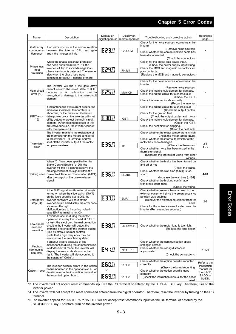
Chapter 5 Error Codes
5 - 3
Error C
odes
to
GA.COM
PH.fail
Main.Cir
IGBT
TH
BRAKE
EMR
OL-LowSP
NET.ERR
OP1-0
OP1-9
Name Description Display on
digital operatorDisplay on
remote operator Troubleshooting and corrective action Reference page
Gate array communica-
tion error
If an error occurs in the communication between the internal CPU and gate array, the inverter will trip.
Check for the noise sources located near the inverter.
(Remove noise sources.)Check whether the communication cable has been disconnected.
(Check the connectors.)
-
Phase loss input
protection
When the phase loss input protection has been enabled (b006 = 01), the inverter will trip to avoid damage if an phase loss input is detected. The inverter trips when the phase loss input continues for about 1 second or more.
Check for the phase loss power input. (Check the power supply input wiring.)
Check the MCB and magnetic contactors for poor contacts. (Replace the MCB and magnetic contactors.)
-
Main circuit error (*3)
The inverter will trip if the gate array cannot confirm the on/off state of IGBT because of a malfunction due to noise,short or damage to the main circuit element.
Check for the noise sources located near the inverter.
(Remove noise sources.)Check the main circuit element for damage. Check the output circuit for a short circuit.
(Check the IGBT.)Check the inverter for abnormality.
(Repair the inverter.)
-
IGBT error (*5)
If instantaneous overcurrent occurs, the main circuit element temperature is abnormal, or the main circuit element drive power drops, the inverter will shut off its output to protect the main circuit element. (After tripping because of this protective function, the inverter cannot retry the operation.)
Check the output circuit for a short circuit. (Check the output cables.)
Check for the ground fault. (Check the output cables and motor.)
Check the main circuit element for damage. (Check the IGBT.)
Check the heat sink for clogging. (Clean the heat sink.)
-
Thermistor error
The inverter monitors the resistance of the thermistor (in the motor) connected to the inverter's TH terminal, and will shut off the inverter output if the motor temperature rises.
Check whether the motor temperature is high.(Check the motor temperature.)
Check whether the internal thermistor of the motor has been damaged.
(Check the thermistor.)Check whether noise has been mixed in the thermistor signal.
(Separate the thermistor wiring from other wirings.)
2-8 4-72
Braking error
When "01" has been specified for the Brake Control Enable (b120), the inverter will trip if it cannot receive the braking confirmation signal within the Brake Wait Time for Confirmation (b124) after the output of the brake release signal.
Check whether the brake has been turned on and off or not.
(Check the brake.)Check whether the wait time (b124) is too short.
(Increase the wait time [b124].)Check whether the braking confirmation signal has been input.
(Check the wiring.)
4-81
Emergency stop (*4)
If the EMR signal (on three terminals) is turned on when the slide switch (SW1) on the logic board is set to ON, the inverter hardware will shut off the inverter output and display the error code shown on the right. Malfunction due to incoming noise,in case EMR terminal is not ON.
Check whether an error has occurred in the external equipment since the emergency stop function was enabled.
(Recover the external equipment from the error.)
Check for the noise sources located near the inverter.(Remove noise sources.)
2-8
Low-speed overload
protection
If overload occurs during the motor operation at a very low speed at 0.2 Hz or less, the electronic thermal protection circuit in the inverter will detect the overload and shut off the inverter output. (2nd electronic thermal control) (Note that a high frequency may be recorded as the error history data.)
Check whether the motor load is too high. (Reduce the load factor.) -
Modbus communica-
tion error
If timeout occurs because of line disconnection during the communication in Modbus-RTU mode, the inverter will display the error code shown on the right. (The inverter will trip according to the setting of "C076".)
Check whether the communication speed setting is correct. Check whether the wiring distance is appropriate.
(Check the connections.)
4-129
Option 1 error
The inverter detects errors in the option board mounted in the optional slot 1. For details, refer to the instruction manual for the mounted option board.
Check whether the option board is mounted correctly.
(Check the board mounting.)Check whether the option board is used correctly.
(Check the instruction manual for the option board.)
Refer to the instruction manual for the SJ-FB, SJ-DG, or SJ-DN.
*3 The inverter will not accept reset commands input via the RS terminal or entered by the STOP/RESET key. Therefore, turn off the inverter power.
*4 The inverter will not accept the reset command entered from the digital operator. Therefore, reset the inverter by turning on the RS terminal.
*5 The inverter applied for 055HF,075 to 150HFF will not accept reset commands input via the RS terminal or entered by the STOP/RESET key. Therefore, turn off the inverter power.
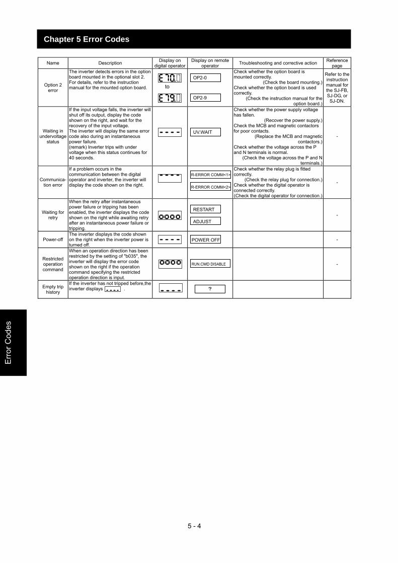
5 - 4
Err
or C
odes
Chapter 5 Error Codes
Name Description Display on
digital operatorDisplay on remote
operator Troubleshooting and corrective action Reference page
Option 2 error
The inverter detects errors in the option board mounted in the optional slot 2. For details, refer to the instruction manual for the mounted option board.
Check whether the option board is mounted correctly.
(Check the board mounting.) Check whether the option board is used correctly.
(Check the instruction manual for the option board.)
Refer to the instruction manual for the SJ-FB, SJ-DG, or SJ-DN.
Waiting in undervoltage
status
If the input voltage falls, the inverter will shut off its output, display the code shown on the right, and wait for the recovery of the input voltage. The inverter will display the same error code also during an instantaneous power failure. (remark) Inverter trips with under voltage when this status continues for 40 seconds.
Check whether the power supply voltage has fallen.
(Recover the power supply.) Check the MCB and magnetic contactors for poor contacts.
(Replace the MCB and magnetic contactors.)
Check whether the voltage across the P and N terminals is normal.
(Check the voltage across the P and N terminals.)
-
Communica- tion error
If a problem occurs in the communication between the digital operator and inverter, the inverter will display the code shown on the right.
Check whether the relay plug is fitted correctly.
(Check the relay plug for connection.) Check whether the digital operator is connected correctly. (Check the digital operator for connection.)
-
Waiting for retry
When the retry after instantaneous power failure or tripping has been enabled, the inverter displays the code shown on the right while awaiting retry after an instantaneous power failure or tripping.
-
Power-off The inverter displays the code shown on the right when the inverter power is turned off.
-
Restricted operation command
When an operation direction has been restricted by the setting of "b035", the inverter will display the error code shown on the right if the operation command specifying the restricted operation direction is input.
-
Empty trip history
If the inverter has not tripped before,the inverter displays .
?
to
OP2-0
OP2-9
UV.WAIT
R-ERROR COMM<1>
RESTART
ADJUST
POWER OFF
RUN.CMD DISABLE
R-ERROR COMM<2>
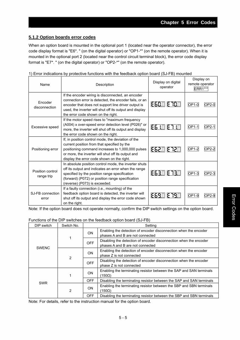
Chapter 5 Error Codes
5 - 5
Error C
odes
5.1.2 Option boards error codes
When an option board is mounted in the optional port 1 (located near the operator connector), the error code display format is "E6*. " (on the digital operator) or "OP1-*" (on the remote operator). When it is mounted in the optional port 2 (located near the control circuit terminal block), the error code display format is "E7*. " (on the digital operator) or "OP2-*" (on the remote operator). 1) Error indications by protective functions with the feedback option board (SJ-FB) mounted
Name Description Display on digital
operator
Display on remote operator
ERR1***
Encoder disconnection
If the encoder wiring is disconnected, an encoder connection error is detected, the encoder fails, or an encoder that does not support line driver output is used, the inverter will shut off its output and display the error code shown on the right.
OP1-0 OP2-0
Excessive speed
If the motor speed rises to "maximum frequency (A004) x over-speed error detection level (P026)" or more, the inverter will shut off its output and display the error code shown on the right.
OP1-1 OP2-1
Positioning error
If, in position control mode, the deviation of the current position from that specified by the positioning command increases to 1,000,000 pulses or more, the inverter will shut off its output and display the error code shown on the right.
OP1-2 OP2-2
Position control range trip
In absolute position control mode, the inverter shuts off its output and indicates an error when the range specified by the position range specification (forward) (P072) or position range specification (reverse) (P073) is exceeded.
OP1-3 OP2-3
SJ-FB connection error
If a faulty connection (i.e., mounting) of the feedback option board is detected, the inverter will shut off its output and display the error code shown on the right.
OP1-9 OP2-9
Note: If the option board does not operate normally, confirm the DIP switch settings on the option board. Functions of the DIP switches on the feedback option board (SJ-FB)
DIP switch Switch No. Setting
ON Enabling the detection of encoder disconnection when the encoder phases A and B are not connected
1 OFF
Disabling the detection of encoder disconnection when the encoder phases A and B are not connected
ON Enabling the detection of encoder disconnection when the encoder phase Z is not connected
SWENC
2 OFF
Disabling the detection of encoder disconnection when the encoder phase Z is not connected
ON Enabling the terminating resistor between the SAP and SAN terminals (150Ω) 1
OFF Disabling the terminating resistor between the SAP and SAN terminals
ON Enabling the terminating resistor between the SBP and SBN terminals (150Ω)
SWR
2 OFF Disabling the terminating resistor between the SBP and SBN terminals
Note: For details, refer to the instruction manual for the option board.
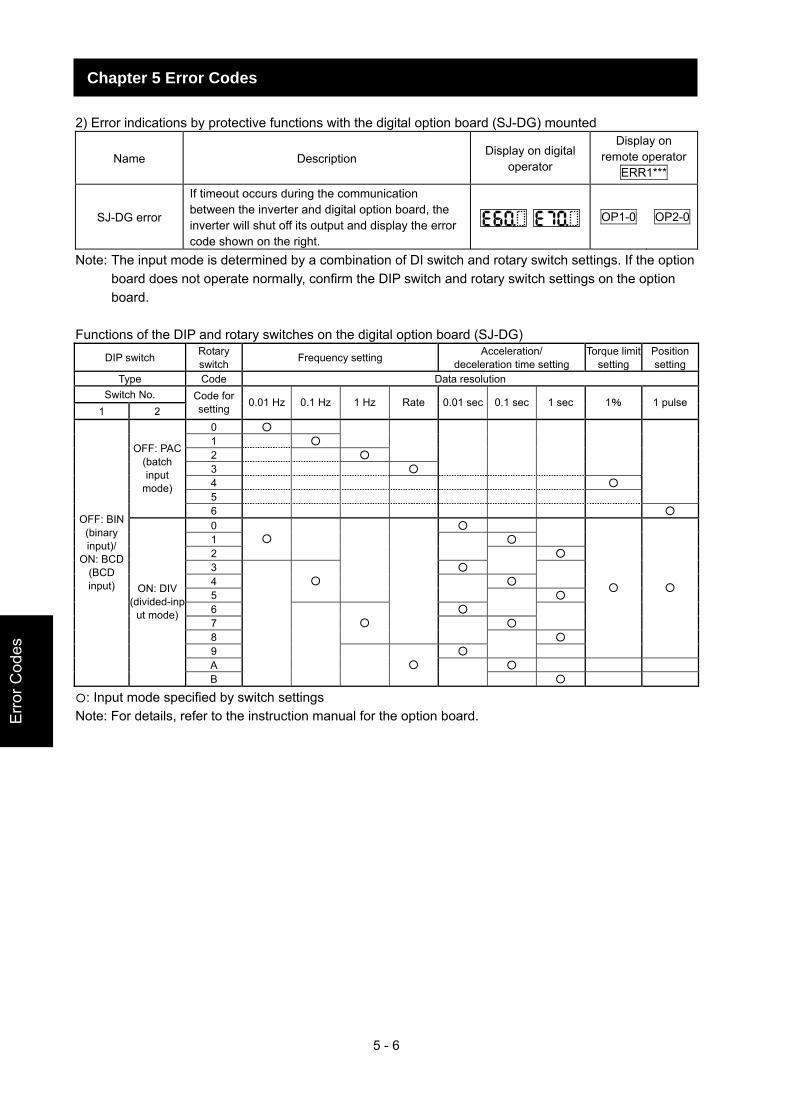
5 - 6
Err
or C
odes
Chapter 5 Error Codes
2) Error indications by protective functions with the digital option board (SJ-DG) mounted
Name Description Display on digital
operator
Display on remote operator
ERR1***
SJ-DG error
If timeout occurs during the communication between the inverter and digital option board, the inverter will shut off its output and display the error code shown on the right.
OP1-0 OP2-0
Note: The input mode is determined by a combination of DI switch and rotary switch settings. If the option board does not operate normally, confirm the DIP switch and rotary switch settings on the option board.
Functions of the DIP and rotary switches on the digital option board (SJ-DG)
DIP switch Rotary switch Frequency setting Acceleration/
deceleration time setting Torque limit
setting Position setting
Type Code Data resolution Switch No.
1 2 Code for setting 0.01 Hz 0.1 Hz 1 Hz Rate 0.01 sec 0.1 sec 1 sec 1% 1 pulse
0 1
2
3
4 5
OFF: PAC
(batch input
mode)
6 0 1
2
3 4
5
6 7
8
9
A
OFF: BIN (binary input)/
ON: BCD (BCD input) ON: DIV
(divided-input mode)
B
: Input mode specified by switch settings Note: For details, refer to the instruction manual for the option board.
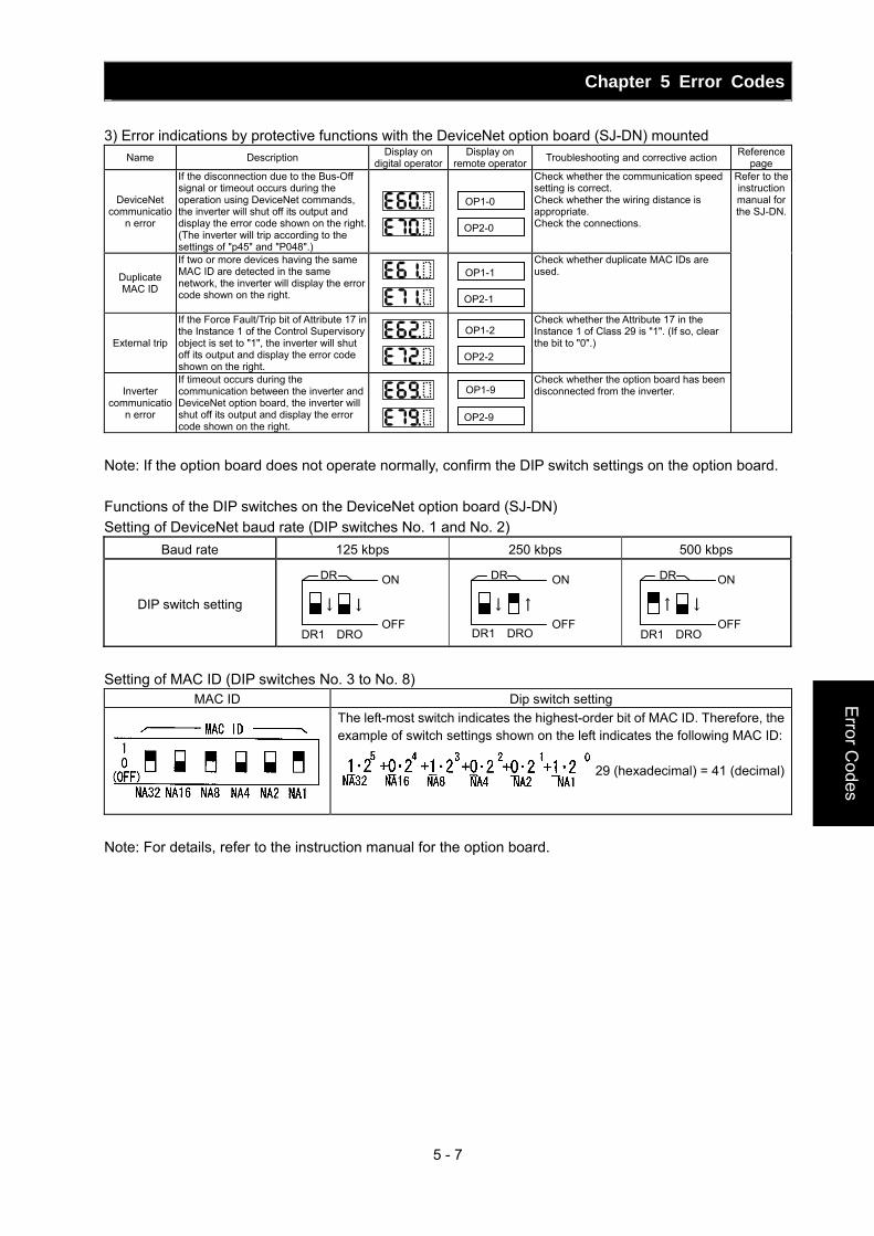
Chapter 5 Error Codes
5 - 7
Error C
odes
OP1-9
OP2-9
OP1-2
OP2-2
OP1-0
OP2-0
OP1-1
OP2-1
3) Error indications by protective functions with the DeviceNet option board (SJ-DN) mounted Name Description Display on
digital operatorDisplay on
remote operator Troubleshooting and corrective action Reference page
DeviceNet communicatio
n error
If the disconnection due to the Bus-Off signal or timeout occurs during the operation using DeviceNet commands, the inverter will shut off its output and display the error code shown on the right.(The inverter will trip according to the settings of "p45" and "P048".)
Check whether the communication speed setting is correct. Check whether the wiring distance is appropriate. Check the connections.
Duplicate MAC ID
If two or more devices having the same MAC ID are detected in the same network, the inverter will display the error code shown on the right.
Check whether duplicate MAC IDs are used.
External trip
If the Force Fault/Trip bit of Attribute 17 in the Instance 1 of the Control Supervisory object is set to "1", the inverter will shut off its output and display the error code shown on the right.
Check whether the Attribute 17 in the Instance 1 of Class 29 is "1". (If so, clear the bit to "0".)
Inverter communicatio
n error
If timeout occurs during the communication between the inverter and DeviceNet option board, the inverter will shut off its output and display the error code shown on the right.
Check whether the option board has been disconnected from the inverter.
Refer to the instruction manual for the SJ-DN.
Note: If the option board does not operate normally, confirm the DIP switch settings on the option board. Functions of the DIP switches on the DeviceNet option board (SJ-DN) Setting of DeviceNet baud rate (DIP switches No. 1 and No. 2)
Baud rate 125 kbps 250 kbps 500 kbps
DIP switch setting
Setting of MAC ID (DIP switches No. 3 to No. 8)
MAC ID Dip switch setting
The left-most switch indicates the highest-order bit of MAC ID. Therefore, the example of switch settings shown on the left indicates the following MAC ID:
= 29 (hexadecimal) = 41 (decimal)
Note: For details, refer to the instruction manual for the option board.
↓↓
ON
OFFDR1 DRO
DR
↑↓
ON
OFFDR1 DRO
DR
↓↑
ON
OFFDR1 DRO
DR
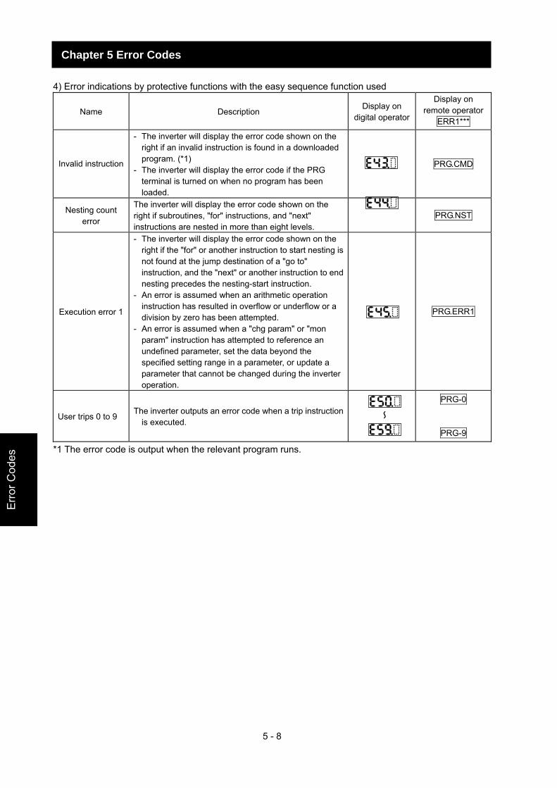
5 - 8
Err
or C
odes
Chapter 5 Error Codes
4) Error indications by protective functions with the easy sequence function used
Name Description Display on
digital operator
Display on remote operator
ERR1***
Invalid instruction
- The inverter will display the error code shown on the right if an invalid instruction is found in a downloaded program. (*1)
- The inverter will display the error code if the PRG terminal is turned on when no program has been loaded.
PRG.CMD
Nesting count error
The inverter will display the error code shown on the right if subroutines, "for" instructions, and "next" instructions are nested in more than eight levels.
PRG.NST
Execution error 1
- The inverter will display the error code shown on the right if the "for" or another instruction to start nesting is not found at the jump destination of a "go to" instruction, and the "next" or another instruction to end nesting precedes the nesting-start instruction.
- An error is assumed when an arithmetic operation instruction has resulted in overflow or underflow or a division by zero has been attempted.
- An error is assumed when a "chg param" or "mon param" instruction has attempted to reference an undefined parameter, set the data beyond the specified setting range in a parameter, or update a parameter that cannot be changed during the inverter operation.
PRG.ERR1
User trips 0 to 9 The inverter outputs an error code when a trip instruction
is executed.
PRG-0
PRG-9
*1 The error code is output when the relevant program runs.
~
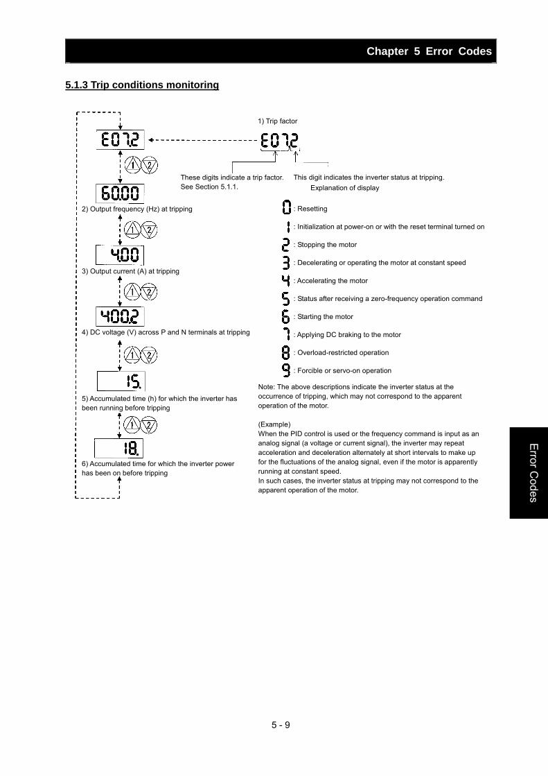
Chapter 5 Error Codes
5 - 9
Error C
odes
5.1.3 Trip conditions monitoring
: Resetting : Initialization at power-on or with the reset terminal turned on : Stopping the motor : Decelerating or operating the motor at constant speed : Accelerating the motor : Status after receiving a zero-frequency operation command : Starting the motor : Applying DC braking to the motor : Overload-restricted operation : Forcible or servo-on operation
1) Trip factor
These digits indicate a trip factor.See Section 5.1.1.
This digit indicates the inverter status at tripping.
2) Output frequency (Hz) at tripping
3) Output current (A) at tripping
4) DC voltage (V) across P and N terminals at tripping
5) Accumulated time (h) for which the inverter has been running before tripping
6) Accumulated time for which the inverter power has been on before tripping
Explanation of display
Note: The above descriptions indicate the inverter status at the occurrence of tripping, which may not correspond to the apparent operation of the motor. (Example) When the PID control is used or the frequency command is input as an analog signal (a voltage or current signal), the inverter may repeat acceleration and deceleration alternately at short intervals to make up for the fluctuations of the analog signal, even if the motor is apparently running at constant speed. In such cases, the inverter status at tripping may not correspond to the apparent operation of the motor.
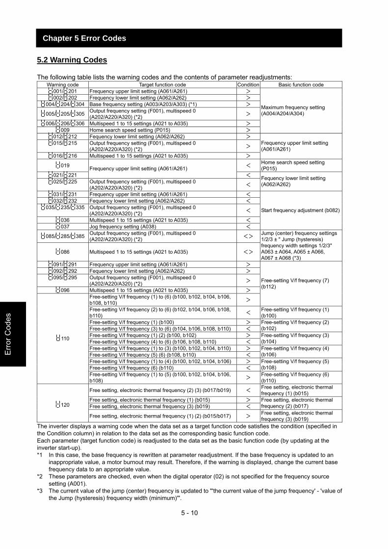
5 - 10
Err
or C
odes
Chapter 5 Error Codes
5.2 Warning Codes
The following table lists the warning codes and the contents of parameter readjustments: Warning code Target function code Condition Basic function code
001/ 201 Frequency upper limit setting (A061/A261) > 002/ 202 Frequency lower limit setting (A062/A262) >
004/ 204/ 304 Base frequency setting (A003/A203/A303) (*1) >
005/ 205/ 305 Output frequency setting (F001), multispeed 0 (A202/A220/A320) (*2) >
006/ 206/ 306 Multispeed 1 to 15 settings (A021 to A035) > 009 Home search speed setting (P015) >
Maximum frequency setting (A004/A204/A304)
012/ 212 Fequency lower limit setting (A062/A262) > 015/ 215 Output frequency setting (F001), multispeed 0
(A202/A220/A320) (*2) >
016/ 216 Multispeed 1 to 15 settings (A021 to A035) >
Frequency upper limit setting (A061/A261)
019 < Home search speed setting (P015)
021/ 221 Frequency upper limit setting (A061/A261)
< 025/ 225 Output frequency setting (F001), multispeed 0
(A202/A220/A320) (*2) < Fequency lower limit setting (A062/A262)
031/ 231 Frequency upper limit setting (A061/A261) < 032/ 232 Fequency lower limit setting (A062/A262) <
035/ 235/ 335 Output frequency setting (F001), multispeed 0 (A202/A220/A320) (*2) <
036 Multispeed 1 to 15 settings (A021 to A035) < 037 Jog frequency setting (A038) <
Start frequency adjustment (b082)
085/ 285/ 385 Output frequency setting (F001), multispeed 0 (A202/A220/A320) (*2) <>
086 Multispeed 1 to 15 settings (A021 to A035) <>
Jump (center) frequency settings 1/2/3 ± " Jump (hysteresis) frequency width settings 1/2/3" A063 ± A064, A065 ± A066, A067 ± A068 (*3)
091/ 291 Frequency upper limit setting (A061/A261) > 092/ 292 Fequency lower limit setting (A062/A262) > 095/ 295 Output frequency setting (F001), multispeed 0
(A202/A220/A320) (*2) >
096 Multispeed 1 to 15 settings (A021 to A035) > Free-setting V/f frequency (1) to (6) (b100, b102, b104, b106, b108, b110) >
Free-setting V/f frequency (7) (b112)
Free-setting V/f frequency (2) to (6) (b102, b104, b106, b108, b110) < Free-setting V/f frequency (1)
(b100) Free-setting V/f frequency (1) (b100) > Free-setting V/f frequency (3) to (6) (b104, b106, b108, b110) <
Free-setting V/f frequency (2) (b102)
Free-setting V/f frequency (1) (2) (b100, b102) > Free-setting V/f frequency (4) to (6) (b106, b108, b110) <
Free-setting V/f frequency (3) (b104)
Free-setting V/f frequency (1) to (3) (b100, b102, b104, b110) > Free-setting V/f frequency (5) (6) (b108, b110) <
Free-setting V/f frequency (4) (b106)
Free-setting V/f frequency (1) to (4) (b100, b102, b104, b106) > Free-setting V/f frequency (6) (b110) <
Free-setting V/f frequency (5) (b108)
110
Free-setting V/f frequency (1) to (5) (b100, b102, b104, b106, b108) > Free-setting V/f frequency (6)
(b110)
Free setting, electronic thermal frequency (2) (3) (b017/b019) < Free setting, electronic thermal frequency (1) (b015)
Free setting, electronic thermal frequency (1) (b015) > Free setting, electronic thermal frequency (3) (b019) <
Free setting, electronic thermal frequency (2) (b017) 120
Free setting, electronic thermal frequency (1) (2) (b015/b017) > Free setting, electronic thermal frequency (3) (b019)
The inverter displays a warning code when the data set as a target function code satisfies the condition (specified in the Condition column) in relation to the data set as the corresponding basic function code. Each parameter (target function code) is readjusted to the data set as the basic function code (by updating at the inverter start-up). *1 In this case, the base frequency is rewritten at parameter readjustment. If the base frequency is updated to an
inappropriate value, a motor burnout may result. Therefore, if the warning is displayed, change the current base frequency data to an appropriate value.
*2 These parameters are checked, even when the digital operator (02) is not specified for the frequency source setting (A001).
*3 The current value of the jump (center) frequency is updated to "'the current value of the jump frequency' - 'value of the Jump (hysteresis) frequency width (minimum)'".
Chapter 6 Maintenance and Inspection This chapter describes the precautions and procedures for the maintenance and inspection of the inverter.
6.1 Precautions for Maintenance and
Inspection ......................................................... 6-1 6.2 Daily and Periodic Inspections ......................... 6-2 6.3 Ground Resistance Test with a Megger ........... 6-3 6.4 Withstand Voltage Test..................................... 6-3 6.5 Method of Checking the Inverter and
Converter Circuits............................................. 6-4
6.6 DC-Bus Capacitor Life Curve........................... 6-5 6.7 Output of Life Warning ..................................... 6-5
6.8 Methods of Measuring the Input/Output Voltages, Current, and Power .......................... 6-6
Maintenance
and Inspection

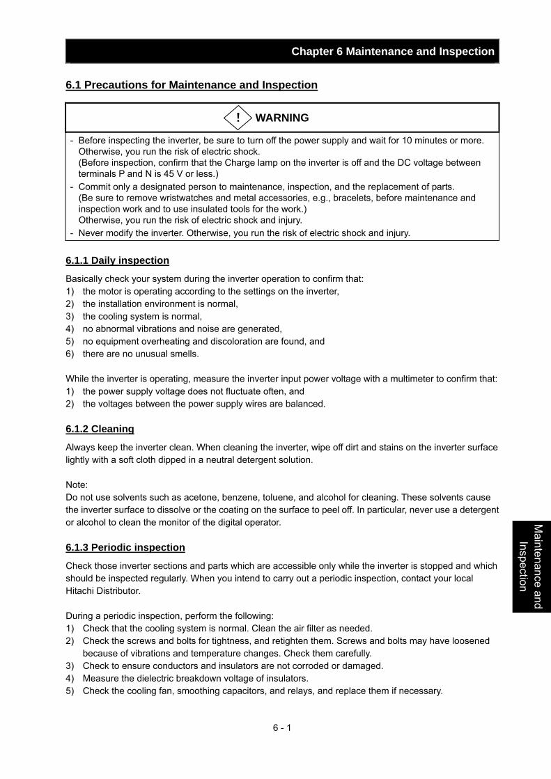
Chapter 6 Maintenance and Inspection
6 - 1
Maintenance and
Inspection
6.1 Precautions for Maintenance and Inspection
WARNING
- Before inspecting the inverter, be sure to turn off the power supply and wait for 10 minutes or more. Otherwise, you run the risk of electric shock. (Before inspection, confirm that the Charge lamp on the inverter is off and the DC voltage between terminals P and N is 45 V or less.)
- Commit only a designated person to maintenance, inspection, and the replacement of parts. (Be sure to remove wristwatches and metal accessories, e.g., bracelets, before maintenance and inspection work and to use insulated tools for the work.) Otherwise, you run the risk of electric shock and injury.
- Never modify the inverter. Otherwise, you run the risk of electric shock and injury. 6.1.1 Daily inspection
Basically check your system during the inverter operation to confirm that: 1) the motor is operating according to the settings on the inverter, 2) the installation environment is normal, 3) the cooling system is normal, 4) no abnormal vibrations and noise are generated, 5) no equipment overheating and discoloration are found, and 6) there are no unusual smells. While the inverter is operating, measure the inverter input power voltage with a multimeter to confirm that: 1) the power supply voltage does not fluctuate often, and 2) the voltages between the power supply wires are balanced. 6.1.2 Cleaning
Always keep the inverter clean. When cleaning the inverter, wipe off dirt and stains on the inverter surface lightly with a soft cloth dipped in a neutral detergent solution. Note: Do not use solvents such as acetone, benzene, toluene, and alcohol for cleaning. These solvents cause the inverter surface to dissolve or the coating on the surface to peel off. In particular, never use a detergent or alcohol to clean the monitor of the digital operator. 6.1.3 Periodic inspection
Check those inverter sections and parts which are accessible only while the inverter is stopped and which should be inspected regularly. When you intend to carry out a periodic inspection, contact your local Hitachi Distributor. During a periodic inspection, perform the following: 1) Check that the cooling system is normal. Clean the air filter as needed. 2) Check the screws and bolts for tightness, and retighten them. Screws and bolts may have loosened
because of vibrations and temperature changes. Check them carefully. 3) Check to ensure conductors and insulators are not corroded or damaged. 4) Measure the dielectric breakdown voltage of insulators. 5) Check the cooling fan, smoothing capacitors, and relays, and replace them if necessary.
!
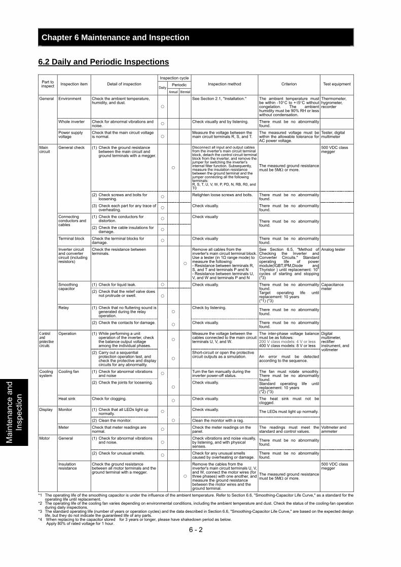
Chapter 6 Maintenance and Inspection
6 - 2
Mai
nten
ance
and
In
spec
tion
6.2 Daily and Periodic Inspections
Inspection cycle
PeriodicPart to inspect Inspection item Detail of inspection
DailyAnnual Biennial
Inspection method Criterion Test equipment
Environment Check the ambient temperature, humidity, and dust.
See Section 2.1, "Installation." The ambient temperature must be within -10°C to +45°C without congelation. The ambient humidity must be 90% RH or less without condensation.
Thermometer, hygrometer, recorder
Whole inverter Check for abnormal vibrations and noise. Check visually and by listening. There must be no abnormality
found.
General
Power supply voltage
Check that the main circuit voltage is normal.
Measure the voltage between the main circuit terminals R, S, and T.
The measured voltage must be within the allowable tolerance for AC power voltage.
Tester, digital multimeter
(1) Check the ground resistance between the main circuit and ground terminals with a megger.
Disconnect all input and output cables from the inverter's main circuit terminal block, detach the control circuit terminal block from the inverter, and remove the jumper for switching the inverter's internal filter function. Subsequently, measure the insulation resistance between the ground terminal and the jumper connecting all the following terminals: R, S, T, U, V, W, P, PD, N, RB, R0, and T0
The measured ground resistance must be 5MΩ or more.
500 VDC class megger
(2) Check screws and bolts for loosening. Retighten loose screws and bolts. There must be no abnormality
found.
General check
(3) Check each part for any trace of overheating. Check visually. There must be no abnormality
found.
(1) Check the conductors for distortion. Connecting
conductors and cables
(2) Check the cable insulations for damage.
Check visually There must be no abnormality found.
Terminal block Check the terminal blocks for damage. Check visually There must be no abnormality
found.
Inverter circuit and converter circuit (including resistors)
Check the resistance between terminals.
Remove all cables from the inverter's main circuit terminal block. Use a tester (in 1Ω range mode) to measure the following: - Resistance between terminals R, S, and T and terminals P and N - Resistance between terminals U, V, and W and terminals P and N
See Section 6.5, "Method of Checking the Inverter and Converter Circuits." Standard operating life of power module(IGBT,IPM,Diode and Thyristor ) until replacement: 106 cycles of starting and stopping (*3)
Analog tester
(1) Check for liquid leak. Smoothing capacitor
(2) Check that the relief valve does not protrude or swell.
Check visually. There must be no abnormality found. Target operating life until replacement: 10 years (*1) (*3)
Capacitance meter
(1) Check that no fluttering sound is generated during the relay operation.
Check by listening. There must be no abnormality
found.
Main circuit
Relay
(2) Check the contacts for damage. Check visually. There must be no abnormality found.
(1) While performing a unit operation of the inverter, check the balance output voltage among the individual phases.
Measure the voltage between the cables connected to the main circuit terminals U, V, and W.
The inter-phase voltage balance must be as follows: 200 V class models: 4 V or less 400 V class models: 8 V or less
Control and protective circuits
Operation
(2) Carry out a sequential protection operation test, and check the protective and display circuits for any abnormality.
Short-circuit or open the protective circuit outputs as a simulation. An error must be detected
according to the sequence.
Digital multimeter, rectifier instrument, and voltmeter
(1) Check for abnormal vibrations and noise Turn the fan manually during the
inverter power-off status. Cooling fan
(2) Check the joints for loosening.
Check visually.
The fan must rotate smoothly. There must be no abnormality found. Standard operating life until replacement: 10 years (*2) (*3)
Cooling system
Heat sink Check for clogging. Check visually. The heat sink must not be clogged.
(1) Check that all LEDs light up normally. Check visually. The LEDs must light up normally. Monitor
(2) Clean the monitor. Clean the monitor with a rag.
Display
Meter Check that meter readings are normal. Check the meter readings on the
panel. The readings must meet the standard and control values.
Voltmeter and ammeter
(1) Check for abnormal vibrations and noise.
Check vibrations and noise visually, by listening, and with physical senses.
There must be no abnormality found.
General
(2) Check for unusual smells. Check for any unusual smells caused by overheating or damage.
There must be no abnormality found.
Motor
Insulation resistance
Check the ground resistance between all motor terminals and the ground terminal with a megger.
Remove the cables from the inverter's main circuit terminals U, V, and W, connect the motor wires (for three phases) with one another, and measure the ground resistance between the motor wires and the ground terminal.
The measured ground resistance must be 5MΩ or more.
500 VDC class megger
*1 The operating life of the smoothing capacitor is under the influence of the ambient temperature. Refer to Section 6.6, "Smoothing-Capacitor Life Curve," as a standard for the operating life until replacement.
*2 The operating life of the cooling fan varies depending on environmental conditions, including the ambient temperature and dust. Check the status of the cooling-fan operation during daily inspections.
*3 The standard operating life (number of years or operation cycles) and the data described in Section 6.6, "Smoothing-Capacitor Life Curve," are based on the expected design life, but they do not indicate the guaranteed life of any parts.
*4 When replacing to the capacitor stored for 3 years or longer, please have shakedown period as below. Apply 80% of rated voltage for 1 hour.
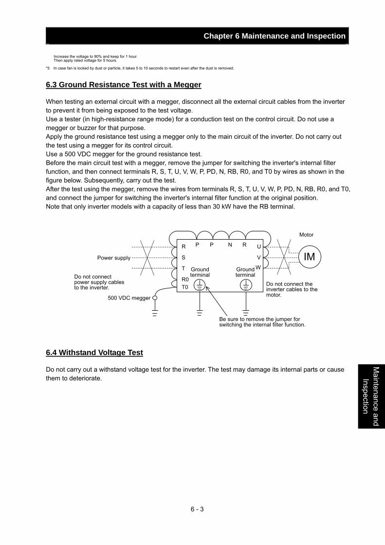
Chapter 6 Maintenance and Inspection
6 - 3
Maintenance and
Inspection
Increase the voltage to 90% and keep for 1 hour. Then apply rated voltage for 5 hours.
*5 In case fan is locked by dust or particle, it takes 5 to 10 seconds to restart even after the dust is removed.
6.3 Ground Resistance Test with a Megger
When testing an external circuit with a megger, disconnect all the external circuit cables from the inverter to prevent it from being exposed to the test voltage. Use a tester (in high-resistance range mode) for a conduction test on the control circuit. Do not use a megger or buzzer for that purpose. Apply the ground resistance test using a megger only to the main circuit of the inverter. Do not carry out the test using a megger for its control circuit. Use a 500 VDC megger for the ground resistance test. Before the main circuit test with a megger, remove the jumper for switching the inverter's internal filter function, and then connect terminals R, S, T, U, V, W, P, PD, N, RB, R0, and T0 by wires as shown in the figure below. Subsequently, carry out the test. After the test using the megger, remove the wires from terminals R, S, T, U, V, W, P, PD, N, RB, R0, and T0, and connect the jumper for switching the inverter's internal filter function at the original position. Note that only inverter models with a capacity of less than 30 kW have the RB terminal.
IM R
S
T
U
V
W
P P N R
R0T0
Power supply
Motor
Ground terminal
Ground terminalDo not connect
power supply cables to the inverter.
500 VDC megger
Be sure to remove the jumper for switching the internal filter function.
Do not connect the inverter cables to the motor.
6.4 Withstand Voltage Test
Do not carry out a withstand voltage test for the inverter. The test may damage its internal parts or cause them to deteriorate.
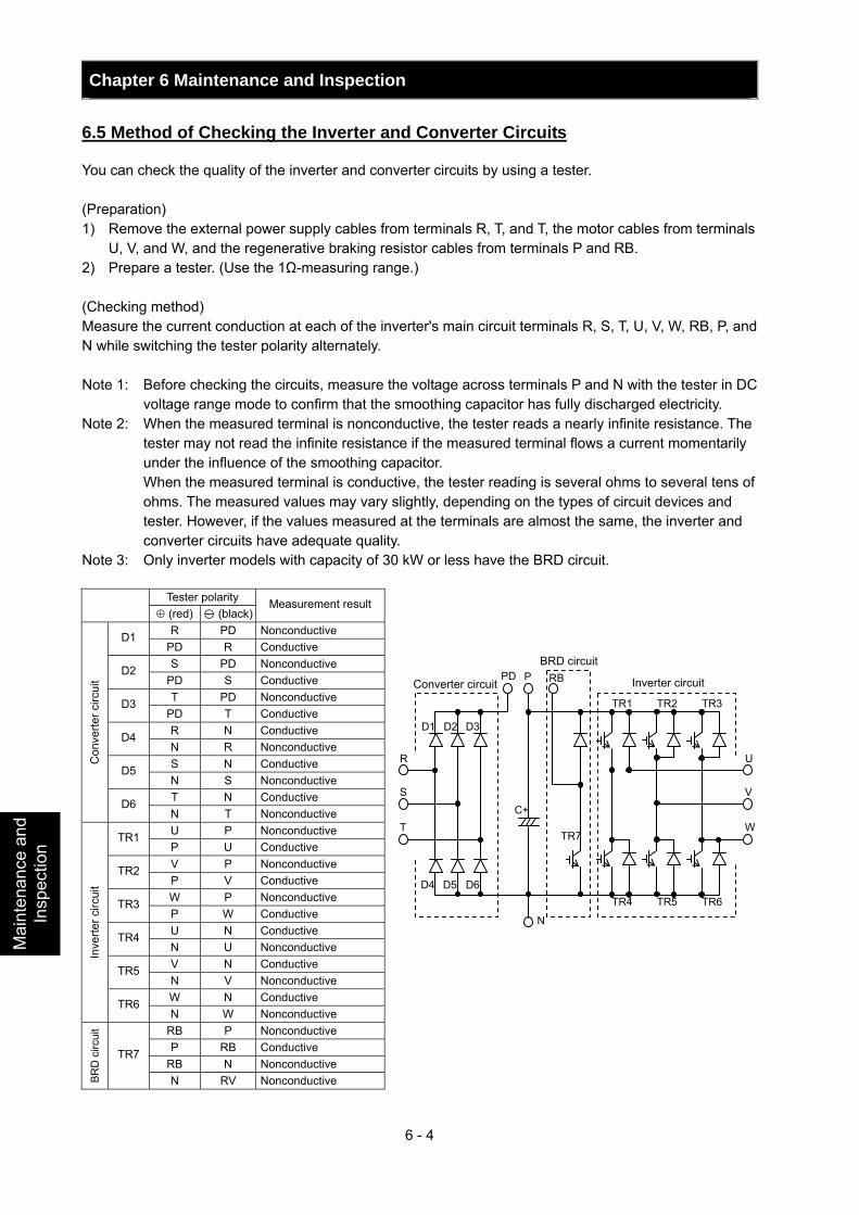
Chapter 6 Maintenance and Inspection
6 - 4
Mai
nten
ance
and
In
spec
tion
6.5 Method of Checking the Inverter and Converter Circuits
You can check the quality of the inverter and converter circuits by using a tester. (Preparation) 1) Remove the external power supply cables from terminals R, T, and T, the motor cables from terminals
U, V, and W, and the regenerative braking resistor cables from terminals P and RB. 2) Prepare a tester. (Use the 1Ω-measuring range.) (Checking method) Measure the current conduction at each of the inverter's main circuit terminals R, S, T, U, V, W, RB, P, and N while switching the tester polarity alternately. Note 1: Before checking the circuits, measure the voltage across terminals P and N with the tester in DC
voltage range mode to confirm that the smoothing capacitor has fully discharged electricity. Note 2: When the measured terminal is nonconductive, the tester reads a nearly infinite resistance. The
tester may not read the infinite resistance if the measured terminal flows a current momentarily under the influence of the smoothing capacitor.
When the measured terminal is conductive, the tester reading is several ohms to several tens of ohms. The measured values may vary slightly, depending on the types of circuit devices and tester. However, if the values measured at the terminals are almost the same, the inverter and converter circuits have adequate quality.
Note 3: Only inverter models with capacity of 30 kW or less have the BRD circuit.
Tester polarity ⊕ (red) (black)
Measurement result
R PD Nonconductive D1 PD R Conductive S PD Nonconductive D2
PD S Conductive T PD Nonconductive D3
PD T Conductive R N Conductive D4 N R Nonconductive S N Conductive D5 N S Nonconductive T N Conductive
Con
verte
r circ
uit
D6 N T Nonconductive U P Nonconductive TR1 P U Conductive V P Nonconductive TR2 P V Conductive W P Nonconductive TR3 P W Conductive U N Conductive TR4 N U Nonconductive V N Conductive TR5 N V Nonconductive W N Conductive
Inve
rter c
ircui
t
TR6 N W Nonconductive
RB P Nonconductive P RB Conductive
RB N Nonconductive
BRD
circ
uit
TR7
N RV Nonconductive
PD
D1
D4
D2
D5
D3
D6
R
S
T
TR4 TR5 TR6
TR1 TR2 TR3
C+
P
N
TR7
RB
U
V
W
Converter circuit
BRD circuit
Inverter circuit
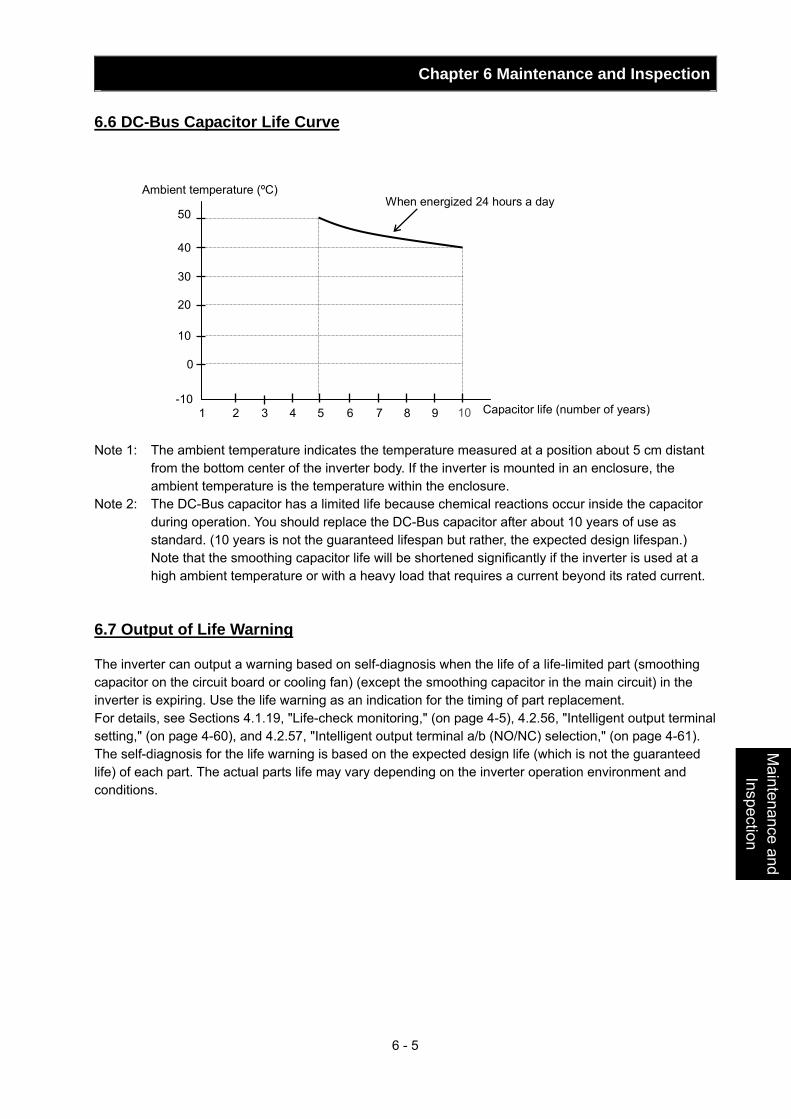
Chapter 6 Maintenance and Inspection
6 - 5
Maintenance and
Inspection
6.6 DC-Bus Capacitor Life Curve
10
20
30
40
50
0
-10 1 2 3 4 5 6 7 8 9 10
Ambient temperature (ºC) When energized 24 hours a day
Capacitor life (number of years) Note 1: The ambient temperature indicates the temperature measured at a position about 5 cm distant
from the bottom center of the inverter body. If the inverter is mounted in an enclosure, the ambient temperature is the temperature within the enclosure.
Note 2: The DC-Bus capacitor has a limited life because chemical reactions occur inside the capacitor during operation. You should replace the DC-Bus capacitor after about 10 years of use as standard. (10 years is not the guaranteed lifespan but rather, the expected design lifespan.)
Note that the smoothing capacitor life will be shortened significantly if the inverter is used at a high ambient temperature or with a heavy load that requires a current beyond its rated current.
6.7 Output of Life Warning
The inverter can output a warning based on self-diagnosis when the life of a life-limited part (smoothing capacitor on the circuit board or cooling fan) (except the smoothing capacitor in the main circuit) in the inverter is expiring. Use the life warning as an indication for the timing of part replacement. For details, see Sections 4.1.19, "Life-check monitoring," (on page 4-5), 4.2.56, "Intelligent output terminal setting," (on page 4-60), and 4.2.57, "Intelligent output terminal a/b (NO/NC) selection," (on page 4-61). The self-diagnosis for the life warning is based on the expected design life (which is not the guaranteed life) of each part. The actual parts life may vary depending on the inverter operation environment and conditions.
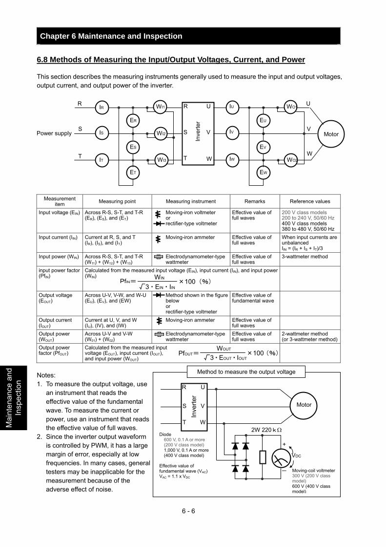
Chapter 6 Maintenance and Inspection
6 - 6
Mai
nten
ance
and
In
spec
tion
6.8 Methods of Measuring the Input/Output Voltages, Current, and Power
This section describes the measuring instruments generally used to measure the input and output voltages, output current, and output power of the inverter.
IR
IS
IT
ER
ET
ES
WI2
WI3
WI1 R
T
S
U
V
W
IU
IV
IW
EU
EW
EV
WO2
WO1
W
V
U R
S
T
Power supply
Inve
rter
Motor
Measurement
item Measuring point Measuring instrument Remarks Reference values
Input voltage (EIN) Across R-S, S-T, and T-R (ER), (ES), and (ET)
Moving-iron voltmeter or rectifier-type voltmeter
Effective value of full waves
200 V class models 200 to 240 V, 50/60 Hz 400 V class models 380 to 480 V, 50/60 Hz
Input current (IIN) Current at R, S, and T (IR), (IS), and (IT)
Moving-iron ammeter Effective value of full waves
When input currents are unbalanced IIN = (IR + IS + IT)/3
Input power (WIN) Across R-S, S-T, and T-R (W11) + (W12) + (W13)
Electrodynamometer-type wattmeter
Effective value of full waves
3-wattmeter method
input power factor (PfIN)
Calculated from the measured input voltage (EIN), input current (IIN), and input power (WIN)
Output voltage (EOUT)
Across U-V, V-W, and W-U (EU), (EV), and (EW)
Method shown in the figure below or rectifier-type voltmeter
Effective value of fundamental wave
Output current (IOUT)
Current at U, V, and W (IU), (IV), and (IW)
Moving-iron ammeter Effective value of full waves
Output power (WOUT)
Across U-V and V-W (W01) + (W02)
Electrodynamometer-type wattmeter
Effective value of full waves
2-wattmeter method (or 3-wattmeter method)
Output power factor (PfOUT)
Calculated from the measured input voltage (EOUT), input current (IOUT), and input power (WOUT)
Notes: 1. To measure the output voltage, use
an instrument that reads the effective value of the fundamental wave. To measure the current or power, use an instrument that reads the effective value of full waves.
2. Since the inverter output waveform is controlled by PWM, it has a large margin of error, especially at low frequencies. In many cases, general testers may be inapplicable for the measurement because of the adverse effect of noise.
Method to measure the output voltage
R
T
S
Inve
rter
U
V
W
Motor
+
-
VDC
2W 220kΩ Diode
600 V, 0.1 A or more (200 V class model) 1,000 V, 0.1 A or more (400 V class model)
Effective value of fundamental wave (VAC)VAC = 1.1 x VDC
Moving-coil voltmeter300 V (200 V class model) 600 V (400 V class model)
PfIN= WIN √3・EIN・IIN
×100(%)
PfOUT=WOUT
√3・EOUT・IOUT×100(%)
Chapter 7 Specifications This chapter describes the specifications and external dimensions of the inverter.
7.1 Specifications ................................................... 7-1
7.2 External dimensions......................................... 7-3
Specifications

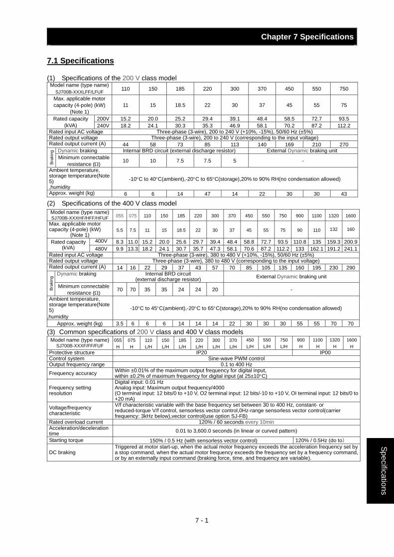
Chapter 7 Specifications
7 - 1
Specifications
7.1 Specifications
(1) Specifications of the 200 V class model Model name (type name)
SJ700B-XXXLFF/LFUF 110 150 185 220 300 370 450 550 750
Max. applicable motor capacity (4-pole) (kW)
(Note 1) 11 15 18.5 22 30 37 45 55 75
200V 15.2 20.0 25.2 29.4 39.1 48.4 58.5 72.7 93.5 Rated capacity (kVA) 240V 18.2 24.1 30.3 35.3 46.9 58.1 70.2 87.2 112.2
Rated input AC voltage Three-phase (3-wire), 200 to 240 V (+10%, -15%), 50/60 Hz (±5%) Rated output voltage Three-phase (3-wire), 200 to 240 V (corresponding to the input voltage) Rated output current (A) 44 58 73 85 113 140 169 210 270
Dynamic braking Internal BRD circuit (external discharge resistor) External Dynamic braking unit
Bra
king
Minimum connectable resistance (Ω) 10 10 7.5 7.5 5 -
Ambient temperature, storage temperature(Note 5) ,humidity
-10°C to 40°C(ambient),-20°C to 65°C(storage),20% to 90% RH(no condensation allowed)
Approx. weight (kg) 6 6 14 47 14 22 30 30 43
(2) Specifications of the 400 V class model Model name (type name) SJ700B-XXXHF/HFF/HFUF 055 075 110 150 185 220 300 370 450 550 750 900 1100 1320 1600
Max. applicable motor capacity (4-pole) (kW)
(Note 1) 5.5 7.5 11 15 18.5 22 30 37 45 55 75 90 110 132 160
400V 8.3 11.0 15.2 20.0 25.6 29.7 39.4 48.4 58.8 72.7 93.5 110.8 135 159.3 200.9Rated capacity (kVA) 480V 9.9 13.3 18.2 24.1 30.7 35.7 47.3 58.1 70.6 87.2 112.2 133 162.1 191.2 241.1
Rated input AC voltage Three-phase (3-wire), 380 to 480 V (+10%, -15%), 50/60 Hz (±5%) Rated output voltage Three-phase (3-wire), 380 to 480 V (corresponding to the input voltage) Rated output current (A) 14 16 22 29 37 43 57 70 85 105 135 160 195 230 290
Dynamic braking Internal BRD circuit (external discharge resistor) External Dynamic braking unit
Bra
king
Minimum connectable resistance (Ω) 70 70 35 35 24 24 20 -
Ambient temperature, storage temperature(Note 5)
,humidity -10°C to 45°C(ambient),-20°C to 65°C(storage),20% to 90% RH(no condensation allowed)
Approx. weight (kg) 3.5 6 6 6 14 14 14 22 30 30 30 55 55 70 70(3) Common specifications of 200 V class and 400 V class models
Model name (type name) SJ700B-XXXF/FF/FUF
055H
075 H
110 L/H
150L/H
185L/H
220L/H
300L/H
370L/H
450L/H
550L/H
750 L/H
900 H
1100 H
1320H
1600H
Protective structure IP20 IP00 Control system Sine-wave PWM control Output frequency range 0.1 to 400 Hz Frequency accuracy Within ±0.01% of the maximum output frequency for digital input,
within ±0.2% of maximum frequency for digital input (at 25±10°C)
Frequency setting resolution
Digital input: 0.01 Hz Analog input: Maximum output frequency/4000 (O terminal input: 12 bits/0 to +10 V, O2 terminal input: 12 bits/-10 to +10 V, OI terminal input: 12 bits/0 to +20 mA)
Voltage/frequency characteristic
V/f characteristic variable with the base frequency set between 30 to 400 Hz, constant- or reduced-torque V/f control, sensorless vector control,0Hz-range sensorless vector control(carrier frequency: 3kHz below),vector control(use option SJ-FB)
Rated overload current 120% / 60 seconds every 10min Acceleration/deceleration time 0.01 to 3,600.0 seconds (in linear or curved pattern)
Starting torque 150% / 0.5 Hz (with sensorless vector control) 120% / 0.5Hz (do to)
DC braking Triggered at motor start-up, when the actual motor frequency exceeds the acceleration frequency set by a stop command, when the actual motor frequency exceeds the frequency set by a frequency command, or by an externally input command (braking force, time, and frequency are variable).
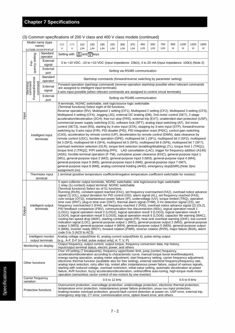
Chapter 7 Specifications
7 - 2
Spec
ifica
tions
(3) Common specifications of 200 V class and 400 V class models (continued) Model name (type
name) SJ700B-XXXF/FF/FUF
055 H
075 H
110 L/H
150 L/H
185L/H
220L/H
300L/H
370L/H
450L/H
550L/H
750L/H
900 H
1100 H
1320H
1600H
Standard operator
Setting with 1 and 2 keys
External signal 0 to +10 VDC, -10 to +10 VDC (input impedance: 10kΩ), 4 to 20 mA (input impedance: 100Ω) (Note 2)
Fre-
qu
ency
set
ting
External port Setting via RS485 communication
Standard operator Start/stop commands (forward/reverse switching by parameter setting)
External signal
Forward-operation start/stop commands (reverse-operation start/stop possible when relevant commands are assigned to intelligent input terminals) 3-wire input possible (when relevant commands are assigned to control circuit terminals) St
art/s
top
com
man
d Fo
rwar
d/re
vers
e co
mm
and
External port Setting via RS485 communication
Intelligent input terminals
8 terminals, NO/NC switchable, sink logic/source logic switchable [Terminal functions] Select eight of 69 functions. Reverse operation (RV), Multispeed 1 setting (CF1), Multispeed 2 setting (CF2), Multispeed 3 setting (CF3), Multispeed 4 setting (CF4), Jogging (JG), external DC braking (DB), 2nd motor control (SET), 2-stage acceleration/deceleration (2CH), free-run stop (FRS), external trip (EXT), unattended start protection (USP), commercial power supply switching (CS), software lock (SFT), analog input switching (AT), 3rd motor control (SET3), reset (RS), starting by 3-wire input (STA), stopping by 3-wire input (STP), forward/reverse switching by 3-wire input (F/R), PID disable (PID), PID integration reset (PIDC), control gain switching (CAS), acceleration by remote control (UP), deceleration by remote control (DWN), data clearance by remote control (UDC), forcible operation (OPE), multispeed bit 1 (SF1), multispeed bit 2 (SF2), multispeed bit 3 (SF3), multispeed bit 4 (SF4), multispeed bit 5 (SF5), multispeed bit 6 (SF6), multispeed bit 7 (SF7), overload restriction selection (OLR), torque limit selection (enabling/disabling) (TL), torque limit 1 (TRQ1), torque limit 2 (TRQ2), P/PI switching (PPI), LAD cancellation (LAC), trigger for frequency addition (A145) (ADD), forcible-terminal operation (F-TM), cumulative power clearance (KHC), general-purpose input 1 (MI1), general-purpose input 2 (MI2), general-purpose input 3 (MI3), general-purpose input 4 (MI4), general-purpose input 5 (MI5), general-purpose input 6 (MI6), general-purpose input 7 (MI7), general-purpose input 8 (MI8), analog command holding (AHD), emergency stop(EMR),(Note 3)no assignment (no)
Inpu
t
Thermistor input terminal
1 terminal (positive temperature coefficient/negative temperature coefficient switchable for resistor)
Intelligent output terminals
5 open-collector output terminals, NO/NC switchable, sink logic/source logic switchable 1 relay (1c-contact) output terminal: NO/NC switchable [Terminal functions] Select six of 51 functions. Running (RUN), constant-speed reached (FA1), set frequency overreached (FA2), overload notice advance signal (1) (OL), output deviation for PID control (OD), alarm signal (AL), set frequency reached (FA3), over-torque (OTQ), instantaneous power failure (IP), undervoltage (UV), torque limited (TRQ), operation time over (RNT), plug-in time over (ONT), thermal alarm signal (THM), 0 Hz detection signal (ZS), set frequency overreached 2 (FA4), set frequency reached 2 (FA5), overload notice advance signal (2) (OL2), PID feedback comparison (FBV), communication line disconnection (NDc), logical operation result 1 (LOG1), logical operation result 2 (LOG2), logical operation result 3 (LOG3), logical operation result 4 (LOG4), logical operation result 5 (LOG5), logical operation result 6 (LOG6), capacitor life warning (WAC), cooling-fan speed drop (WAF), starting contact signal (FR), heat sink overheat warning (OHF), low-current indication signal (LOC), general-purpose output 1 (M01), general-purpose output 2 (M02), general-purpose output 3 (M03), general-purpose output 4 (M04), general-purpose output 5 (M05), general-purpose output 6 (M06), inverter ready (IRDY), forward rotation (FWR), reverse rotation (RVR), major failure (MJA), alarm code 0 to 3 (AC0 to AC3)
Out
put
Intelligent monitor output terminals
Analog voltage output(Note 4), analog current output(Note 4), pulse-string output (e.g., A-F, D-F [n-fold, pulse output only], A, T, V, P)
Monitoring on display Output frequency, output current, output torque, frequency conversion data, trip history, input/output terminal status, electric power, and others
Other functions
Free V/f setting (7 breakpoints), frequency upper/lower limit, jump (center) frequency, acceleration/deceleration according to characteristic curve, manual torque boost level/breakpoint, energy-saving operation, analog meter adjustment, start frequency setting, carrier frequency adjustment, electronic thermal function (available also for free setting), external start/end frequency/frequency rate, analog input selection, retry after trip, restart after instantaneous power failure, output of various signals, starting with reduced voltage, overload restriction, initial-value setting, automatic deceleration at power failure, AVR function, fuzzy acceleration/deceleration, online/offline auto-tuning, high-torque multi-motor operation (sensorless vector control of two motors by one inverter)
Carrier frequency variation 0.5 to 12 kHz 0.5 to 8 kHz
Protective functions Overcurrent protection, overvoltage protection, undervoltage protection, electronic thermal protection, temperature error protection, instantaneous power failure protection, phase loss input protection, braking-resistor overload protection, ground-fault current detection at power-on, USP error, external trip, emergency stop trip, CT error, communication error, option board error, and others
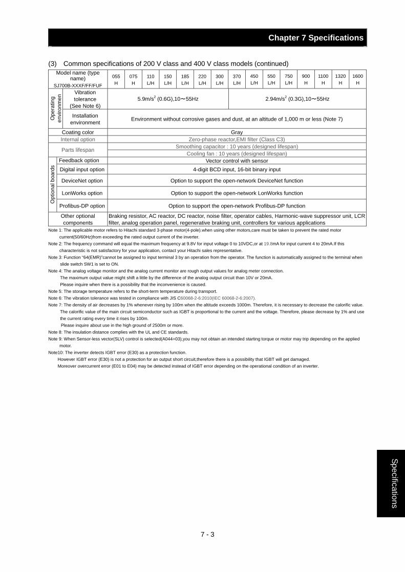
Chapter 7 Specifications
7 - 3
Specifications
(3) Common specifications of 200 V class and 400 V class models (continued) Model name (type
name) SJ700B-XXXF/FF/FUF
055H
075 H
110 L/H
150L/H
185L/H
220L/H
300L/H
370L/H
450L/H
550L/H
750 L/H
900 H
1100 H
1320H
1600H
Vibration tolerance
(See Note 6) 5.9m/s2 (0.6G),10~55Hz 2.94m/s2 (0.3G),10~55Hz
Ope
ratin
g en
viro
nmen
Installation environment Environment without corrosive gases and dust, at an altitude of 1,000 m or less (Note 7)
Coating color Gray Internal option Zero-phase reactor,EMI filter (Class C3)
Smoothing capacitor : 10 years (designed lifespan) Parts lifespan Cooling fan : 10 years (designed lifespan)
Feedback option Vector control with sensor Digital input option 4-digit BCD input, 16-bit binary input
DeviceNet option Option to support the open-network DeviceNet function
LonWorks option Option to support the open-network LonWorks function
Opt
iona
l boa
rds
Profibus-DP option Option to support the open-network Profibus-DP function
Other optional components
Braking resistor, AC reactor, DC reactor, noise filter, operator cables, Harmonic-wave suppressor unit, LCR filter, analog operation panel, regenerative braking unit, controllers for various applications
Note 1: The applicable motor refers to Hitachi standard 3-phase motor(4-pole).when using other motors,care must be taken to prevent the rated motor current(50/60Hz)from exceeding the rated output current of the inverter.
Note 2: The frequency command will equal the maximum frequency at 9.8V for input voltage 0 to 10VDC,or at 19.8mA for input current 4 to 20mA.If this characteristic is not satisfactory for your application, contact your Hitachi sales representative.
Note 3: Function “64(EMR)”cannot be assigned to input terminal 3 by an operation from the operator. The function is automatically assigned to the terminal when slide switch SW1 is set to ON.
Note 4: The analog voltage monitor and the analog current monitor are rough output values for analog meter connection. The maximum output value might shift a little by the difference of the analog output circuit than 10V or 20mA. Please inquire when there is a possibility that the inconvenience is caused.
Note 5: The storage temperature refers to the short-term temperature during transport. Note 6: The vibration tolerance was tested in compliance with JIS C60068-2-6:2010(IEC 60068-2-6:2007). Note 7: The density of air decreases by 1% whenever rising by 100m when the altitude exceeds 1000m. Therefore, it is necessary to decrease the calorific value.
The calorific value of the main circuit semiconductor such as IGBT is proportional to the current and the voltage. Therefore, please decrease by 1% and use the current rating every time it rises by 100m. Please inquire about use in the high ground of 2500m or more.
Note 8: The insulation distance complies with the UL and CE standards. Note 9: When Sensor-less vector(SLV) control is selected(A044=03),you may not obtain an intended starting torque or motor may trip depending on the applied
motor. Note10: The inverter detects IGBT error (E30) as a protection function.
However IGBT error (E30) is not a protection for an output short circuit,therefore there is a possibility that IGBT will get damaged. Moreover overcurrent error (E01 to E04) may be detected instead of IGBT error depending on the operational condition of an inverter.
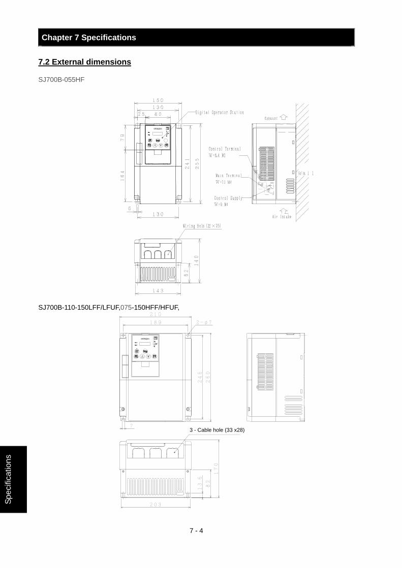
Chapter 7 Specifications
7 - 4
Spec
ifica
tions
7.2 External dimensions
SJ700B-055HF
SJ700B-110-150LFF/LFUF,075-150HFF/HFUF,
3 - Cable hole (33 x28)
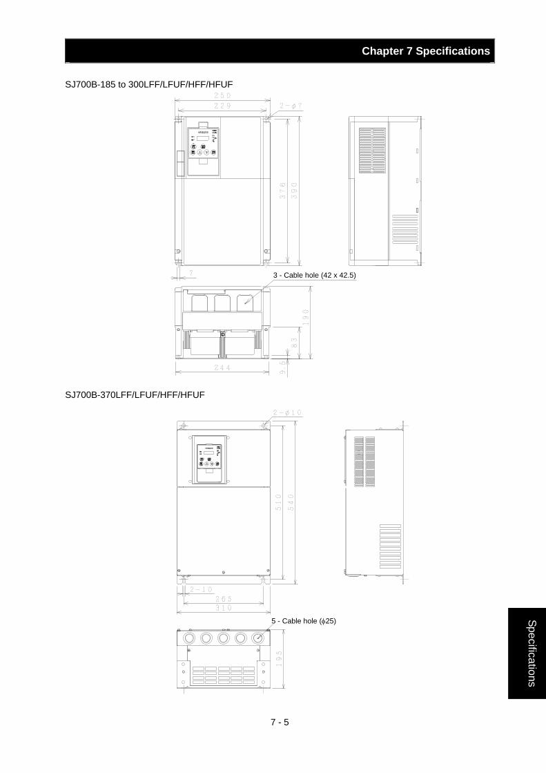
Chapter 7 Specifications
7 - 5
Specifications
SJ700B-185 to 300LFF/LFUF/HFF/HFUF
SJ700B-370LFF/LFUF/HFF/HFUF
3 - Cable hole (42 x 42.5)
5 - Cable hole (φ25)
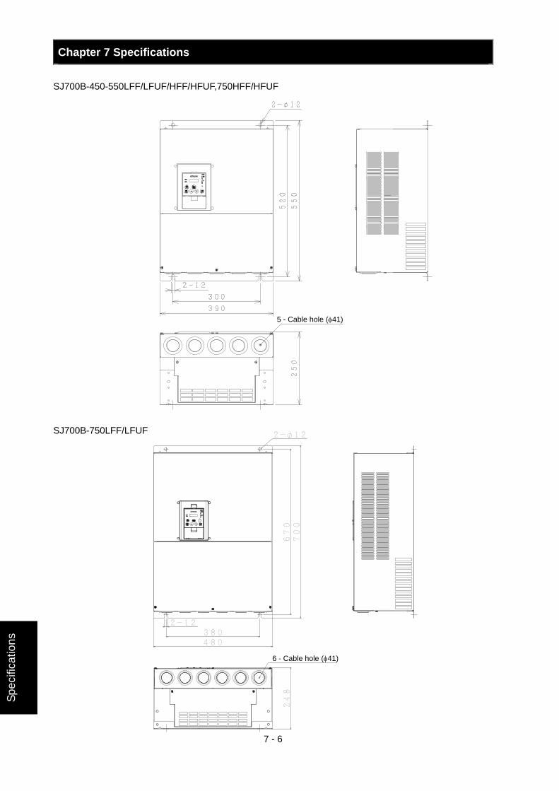
Chapter 7 Specifications
7 - 6
Spec
ifica
tions
SJ700B-450-550LFF/LFUF/HFF/HFUF,750HFF/HFUF SJ700B-750LFF/LFUF
5 - Cable hole (φ41)
6 - Cable hole (φ41)
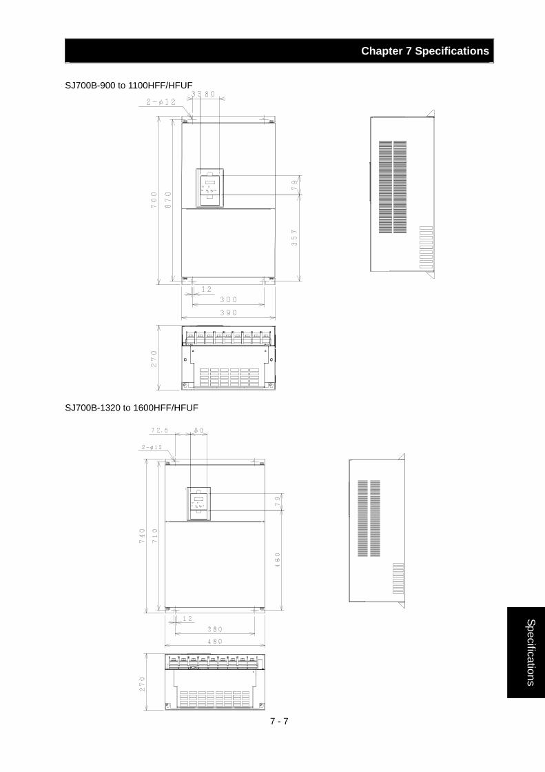
Chapter 7 Specifications
7 - 7
Specifications
SJ700B-900 to 1100HFF/HFUF SJ700B-1320 to 1600HFF/HFUF
Chapter 8 This chapter lists the data settings for the various functions of the inverter.
8.1 Precautions for Data Setting ................8-1 8.2 Monitoring Mode...................................8-1 8.3 Function Mode .....................................8-2
8.4 Extended Function Mode .....................8-3
List of Data
Settings

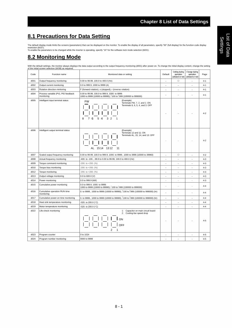
Chapter 8 List of Data Settings
8 - 1
List of Data
Settings
8.1 Precautions for Data Setting The default display mode limits the screens (parameters) that can be displayed on the monitor. To enable the display of all parameters, specify "00" (full display) for the function code display restriction (b037). To enable the parameters to be changed while the inverter is operating, specify "10" for the software lock mode selection (b031).
8.2 Monitoring Mode With the default settings, the monitor always displays the data output according to the output frequency monitoring (d001) after power-on. To change the initial display content, change the setting of the initial-screen selection (b038) as required.
Code Function name Monitored data or setting Default Setting during
operation (allowed or not)
Change during operation
(allowed or not) Page
d001 Output frequency monitoring 0.00 to 99.99, 100.0 to 400.0 (Hz) − − 4-1
d002 Output current monitoring 0.0 to 999.9, 1000 to 9999 (A) − − − 4-1
d003 Rotation direction minitoring F (forward rotation), o (stopped), r (reverse rotation) − − − 4-1
d004 Process variable (PV), PID feedback monitoring
0.00 to 99.99, 100.0 to 999.9, 1000. to 9999. 1000 to 9999 (10000 to 99990), ⎡100 to ⎡999 (100000 to 999000) − − − 4-1
d005 Intelligent input terminal status (Example) Terminals FW, 7, 2, and 1: ON Terminals 8, 6, 5, 4, and 3: OFF
− − − 4-2
d006 Intelligent output terminal status (Example) Terminals 12 and 11: ON Terminals AL, 15, 14, and 13: OFF
− − − 4-2
d007 Scaled output frequency monitoring 0.00 to 99.99, 100.0 to 999.9, 1000. to 9999., 1000 to 3996 (10000 to 39960) − − 4-2
d008 Actual-frequency monitoring -400. to -100., -99.9 to 0.00 to 99.99, 100.0 to 400.0 (Hz) − − − 4-3
d009 Torque command monitoring -200. to +200. (%) − − − 4-3
d010 Torque bias monitoring -200. to +200. (%) − − − 4-3
d012 Torque monitoring -200. to +200. (%) − − − 4-3
d013 Output voltage monitoring 0.0 to 600.0 (V) − − − 4-3
d014 Power monitoring 0.0 to 999.9 (kW) − − − 4-3
d015 Cumulative power monitoring 0.0 to 999.9, 1000. to 9999. 1000 to 9999 (10000 to 99990), ⎡100 to ⎡999 (100000 to 999000) − − − 4-4
d016 Cumulative operation RUN time monitoring
0. to 9999., 1000 to 9999 (10000 to 99990), ⎡100 to ⎡999 (100000 to 999000) (hr) − − − 4-4
d017 Cumulative power-on time monitoring 0. to 9999., 1000 to 9999 (10000 to 99990), ⎡100 to ⎡999 (100000 to 999000) (hr) − − − 4-4
d018 Heat sink temperature monitoring -020. to 200.0 (°C) − − − 4-4
d019 Motor temperature monitoring -020. to 200.0 (°C) − − − 4-4
d022 Life-check monitoring 1: Capacitor on main circuit board 2: Cooling-fan speed drop
− − − 4-5
d023 Program counter 0 to 1024 − − − 4-5
d024 Program number monitoring 0000 to 9999 − − − 4-5
FW
8 7 6 5 4 3 2 1
AL 15 14 13 12 11
2 1
ON
OFF
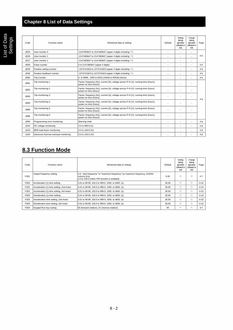
Chapter 8 List of Data Settings
8 - 2
List
of D
ata
Set
tings
Code Function name Monitored data or setting Default
Setting during
operation (allowed or
not)
Change during
operation (allowed or
not)
Page
d025 User monitor 0 -2147483647 to 2147483647 (upper 4 digits including “-“) − − −
d026 User monitor 1 -2147483647 to 2147483647 (upper 4 digits including “-“) − − −
d027 User monitor 2 -2147483647 to 2147483647 (upper 4 digits including “-“) − − −
4-5
d028 Pulse counter 0 to 2147483647 (upper 4 digits) − − − 4-5
d029 Position setting monitor -1073741823 to 1073741823 (upper 4 digits including “-“) − − − 4-5
d030 Position feedback monitor -1073741823 to 1073741823 (upper 4 digits including “-“) − − − 4-5
d080 Trip Counter 0. to 9999., 1000 to 6553 (10000 to 65530) (times) − − − 4-5
d081 Trip monitoring 1 Factor, frequency (Hz), current (A), voltage across P-N (V), running time (hours), power-on time (hours) − − −
d082 Trip monitoring 2 Factor, frequency (Hz), current (A), voltage across P-N (V), running time (hours), power-on time (hours) − − −
d083 Trip monitoring 3 Factor, frequency (Hz), current (A), voltage across P-N (V), running time (hours), power-on time (hours) − − −
d084 Trip monitoring 4 Factor, frequency (Hz), current (A), voltage across P-N (V), running time (hours), power-on time (hours) − − −
d085 Trip monitoring 5 Factor, frequency (Hz), current (A), voltage across P-N (V), running time (hours), power-on time (hours) − − −
d086 Trip monitoring 6 Factor, frequency (Hz), current (A), voltage across P-N (V), running time (hours), power-on time (hours) − − −
4-6
d090 Programming error monitoring Warning code − − − 4-6
d102 DC voltage monitoring 0.0 to 999.9 (V) − − − 4-6
d103 BRD load factor monitoring 0.0 to 100.0 (%) − − − 4-6
d104 Electronic thermal overload monitoring 0.0 to 100.0 (%) − − − 4-6
8.3 Function Mode
Code Function name Monitored data or setting Default
Setting during
operation (allowed or
not)
Change during
operation (allowed or
not)
Page
F001 Output frequency setting 0.0, "start frequency" to "maximum frequency" (or maximum frequency, 2nd/3rd
motors) (Hz) 0.0 to 100.0 (when PID function is enabled)
0.00 4-7
F002 Acceleration (1) time setting 0.01 to 99.99, 100.0 to 999.9, 1000. to 3600. (s) 30.00 4-10
F202 Acceleration (1) time setting, 2nd motor 0.01 to 99.99, 100.0 to 999.9, 1000. to 3600. (s) 30.00 4-10
F302 Acceleration (1) time setting, 3rd motor 0.01 to 99.99, 100.0 to 999.9, 1000. to 3600. (s) 30.00 4-10
F003 Deceleration (1) time setting 0.01 to 99.99, 100.0 to 999.9, 1000. to 3600. (s) 30.00 4-10
F203 Deceleration time setting, 2nd motor 0.01 to 99.99, 100.0 to 999.9, 1000. to 3600. (s) 30.00 4-10
F303 Deceleration time setting, 3rd motor 0.01 to 99.99, 100.0 to 999.9, 1000. to 3600. (s) 30.00 4-10
F004 Keypad Run key routing 00 (forward rotation), 01 (reverse rotation) 00 4-7
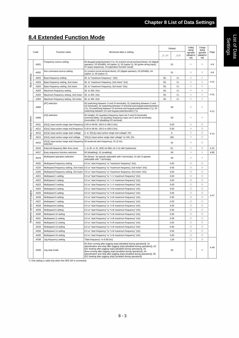
Chapter 8 List of Data Settings
8 - 3
List of Data
Settings
8.4 Extended Function Mode
Default Code Function name Monitored data or setting
_F/_FF _FUF
Setting during
operation (allowed or
not)
Change during
operation (allowed or
not)
Page
A001 Frequency source setting 00 (keypad potentiometer) (*1), 01 (control circuit terminal block), 02 (digital
operator), 03 (RS485), 04 (option 1), 05 (option 2), 06 (pulse-string input), 07 (easy sequence), 10 (operation function result)
01 4-8
A002 Run command source setting 01 (control circuit terminal block), 02 (digital operator), 03 (RS485), 04 (option 1), 05 (option 2) 01 4-8
A003 Base frequency setting 30. to "maximum frequency " (Hz) 50. 60.
A203 Base frequency setting, 2nd motor 30. to "maximum frequency, 2nd motor" (Hz) 50. 60.
A303 Base frequency setting, 3rd motor 30. to "maximum frequency, 3rd motor" (Hz) 50. 60.
4-11
A004 Maximum frequency setting 30. to 400. (Hz) 50. 60.
A204 Maximum frequency setting, 2nd motor 30. to 400. (Hz) 50. 60.
Basi
c se
tting
s
A304 Maximum frequency setting, 3rd motor 30. to 400. (Hz) 50. 60.
4-11
A005
[AT] selection 00 (switching between O and OI terminals), 01 (switching between O and O2 terminals), 02 (switching between O terminal and keypad potentiometer) (*1), 03 (switching between OI terminal and keypad potentiometer) (*1), 04 (switching between O2 and keypad potentiometer) (*1)
00
A006 [O2] selection 00 (single), 01 (auxiliary frequency input via O and OI terminals)
(nonreversible), 02 (auxiliary frequency input via O and OI terminals) (reversible), 03 (disabling O2 terminal)
03
4-12
A011 [O]-[L] input active range start frequency 0.00 to 99.99, 100.0 to 400.0 (Hz) 0.00
A012 [O]-[L] input active range end frequency 0.00 to 99.99, 100.0 to 400.0 (Hz) 0.00
A013 [O]-[L] input active range start voltage 0. to "[O]-[L] input active range end voltage" (%) 0.
A014 [O]-[L] input active range end voltage "[O]-[L] input active range start voltage" to 100. (%) 100.
A015 [O]-[L] input active range start frequency selection
00 (external start frequency), 01 (0 Hz) 01
4-14
A016 External frequency filter time const. 1. to 30. or 31. (500 ms filter ±0.1 Hz with hysteresis) 31. 4-15
Anal
og in
put a
nd o
ther
s
A017 Easy sequence function selection 00 (disabling), 01 (enabling) 00 4-95
A019 Multispeed operation selection 00 (binary: 16 speeds selectable with 4 terminals), 01 (bit: 8 speeds selectable with 7 terminals) 00
A020 Multispeed frequency setting 0.0 or “start frequency” to “maximum frequency” (Hz) 0.00
A220 Multispeed frequency setting, 2nd motor 0.0 or “start frequency” to “maximum frequency, 2nd motor” (Hz) 0.00
A320 Multispeed frequency setting, 3rd motor 0.0 or “start frequency” to “maximum frequency, 3rd motor” (Hz) 0.00
A021 Multispeed 1 setting 0.0 or “start frequency” to “n-th maximum frequency” (Hz) 0.00
A022 Multispeed 2 setting 0.0 or “start frequency” to “n-th maximum frequency” (Hz) 0.00
A023 Multispeed 3 setting 0.0 or “start frequency” to “n-th maximum frequency” (Hz) 0.00
A024 Multispeed 4 setting 0.0 or “start frequency” to “n-th maximum frequency” (Hz) 0.00
A025 Multispeed 5 setting 0.0 or “start frequency” to “n-th maximum frequency” (Hz) 0.00
A026 Multispeed 6 setting 0.0 or “start frequency” to “n-th maximum frequency” (Hz) 0.00
A027 Multispeed 7 setting 0.0 or “start frequency” to “n-th maximum frequency” (Hz) 0.00
A028 Multispeed 8 setting 0.0 or “start frequency” to “n-th maximum frequency” (Hz) 0.00
A029 Multispeed 9 setting 0.0 or “start frequency” to “n-th maximum frequency” (Hz) 0.00
A030 Multispeed 10 setting 0.0 or “start frequency” to “n-th maximum frequency” (Hz) 0.00
A031 Multispeed 11 setting 0.0 or “start frequency” to “n-th maximum frequency” (Hz) 0.00
A032 Multispeed 12 setting 0.0 or “start frequency” to “n-th maximum frequency” (Hz) 0.00
A033 Multispeed 13 setting 0.0 or “start frequency” to “n-th maximum frequency” (Hz) 0.00
A034 Multispeed 14 setting 0.0 or “start frequency” to “n-th maximum frequency” (Hz) 0.00
A035 Multispeed 15 setting 0.0 or “start frequency” to “n-th maximum frequency” (Hz) 0.00
4-47
A038 Jog frequency setting "Start frequency" to 9.99 (Hz) 1.00
Mul
tispe
ed o
pera
tion
and
jogg
ing
A039 Jog stop mode
00 (free-running after jogging stops [disabled during operation]), 01 (deceleration and stop after jogging stops [disabled during operation]), 02 (DC braking after jogging stops [disabled during operation]), 03 (free-running after jogging stops [enabled during operation]), 04 (deceleration and stop after jogging stops [enabled during operation]), 05 (DC braking after jogging stops [enabled during operation])
00 4-49
*1 This setting is valid only when the OPE-SR is connected.
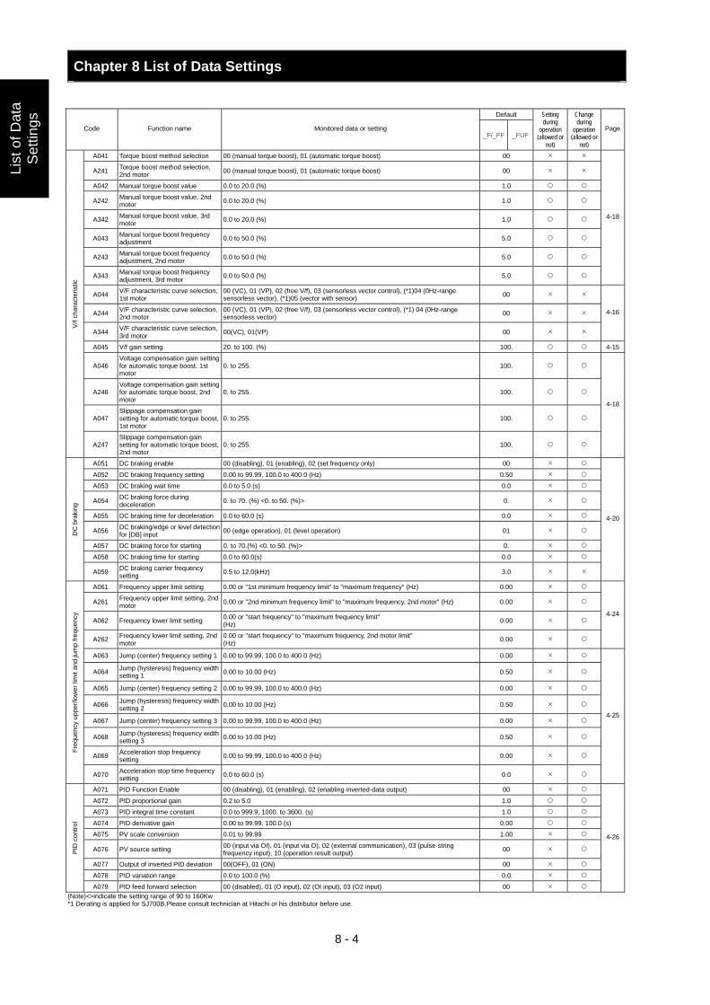
Chapter 8 List of Data Settings
8 - 4
List
of D
ata
Set
tings
Default
Code Function name Monitored data or setting _F/_FF _FUF
Setting during
operation (allowed or
not)
Change during
operation (allowed or
not)
Page
A041 Torque boost method selection 00 (manual torque boost), 01 (automatic torque boost) 00
A241 Torque boost method selection, 2nd motor 00 (manual torque boost), 01 (automatic torque boost) 00
A042 Manual torque boost value 0.0 to 20.0 (%) 1.0
A242 Manual torque boost value, 2nd motor 0.0 to 20.0 (%) 1.0
A342 Manual torque boost value, 3rd motor 0.0 to 20.0 (%) 1.0
A043 Manual torque boost frequency adjustment 0.0 to 50.0 (%) 5.0
A243 Manual torque boost frequency adjustment, 2nd motor 0.0 to 50.0 (%) 5.0
A343 Manual torque boost frequency adjustment, 3rd motor 0.0 to 50.0 (%) 5.0
4-18
A044 V/F characteristic curve selection, 1st motor
00 (VC), 01 (VP), 02 (free V/f), 03 (sensorless vector control), (*1)04 (0Hz-range sensorless vector), (*1)05 (vector with sensor) 00
A244 V/F characteristic curve selection, 2nd motor
00 (VC), 01 (VP), 02 (free V/f), 03 (sensorless vector control), (*1) 04 (0Hz-range sensorless vector) 00
A344 V/F characteristic curve selection, 3rd motor 00(VC), 01(VP) 00
4-16
A045 V/f gain setting 20. to 100. (%) 100. 4-15
A046 Voltage compensation gain setting for automatic torque boost. 1st motor
0. to 255. 100.
A246 Voltage compensation gain setting for automatic torque boost, 2nd motor
0. to 255. 100.
A047 Slippage compensation gain setting for automatic torque boost, 1st motor
0. to 255. 100.
V/f c
hara
cter
istic
A247 Slippage compensation gain setting for automatic torque boost, 2nd motor
0. to 255. 100.
4-18
A051 DC braking enable 00 (disabling), 01 (enabling), 02 (set frequency only) 00
A052 DC braking frequency setting 0.00 to 99.99, 100.0 to 400.0 (Hz) 0.50
A053 DC braking wait time 0.0 to 5.0 (s) 0.0
A054 DC braking force during deceleration 0. to 70. (%) <0. to 50. (%)> 0.
A055 DC braking time for deceleration 0.0 to 60.0 (s) 0.0
A056 DC braking/edge or level detection for [DB] input 00 (edge operation), 01 (level operation) 01
A057 DC braking force for starting 0. to 70.(%) <0. to 50. (%)> 0.
A058 DC braking time for starting 0.0 to 60.0(s) 0.0
DC
bra
king
A059 DC braking carrier frequency setting 0.5 to 12.0(kHz) 3.0
4-20
A061 Frequency upper limit setting 0.00 or "1st minimum frequency limit" to "maximum frequency" (Hz) 0.00
A261 Frequency upper limit setting, 2nd motor 0.00 or "2nd minimum frequency limit" to "maximum frequency, 2nd motor" (Hz) 0.00
A062 Frequency lower limit setting 0.00 or "start frequency" to "maximum frequency limit" (Hz) 0.00
A262 Frequency lower limit setting, 2nd motor
0.00 or "start frequency" to "maximum frequency, 2nd motor limit" (Hz) 0.00
4-24
A063 Jump (center) frequency setting 1 0.00 to 99.99, 100.0 to 400.0 (Hz) 0.00
A064 Jump (hysteresis) frequency width setting 1 0.00 to 10.00 (Hz) 0.50
A065 Jump (center) frequency setting 2 0.00 to 99.99, 100.0 to 400.0 (Hz) 0.00
A066 Jump (hysteresis) frequency width setting 2 0.00 to 10.00 (Hz) 0.50
A067 Jump (center) frequency setting 3 0.00 to 99.99, 100.0 to 400.0 (Hz) 0.00
A068 Jump (hysteresis) frequency width setting 3 0.00 to 10.00 (Hz) 0.50
A069 Acceleration stop frequency setting 0.00 to 99.99, 100.0 to 400.0 (Hz) 0.00
Freq
uenc
y up
per/l
ower
lim
it an
d ju
mp
frequ
ency
A070 Acceleration stop time frequency setting 0.0 to 60.0 (s) 0.0
4-25
A071 PID Function Enable 00 (disabling), 01 (enabling), 02 (enabling inverted-data output) 00
A072 PID proportional gain 0.2 to 5.0 1.0
A073 PID integral time constant 0.0 to 999.9, 1000. to 3600. (s) 1.0
A074 PID derivative gain 0.00 to 99.99, 100.0 (s) 0.00
A075 PV scale conversion 0.01 to 99.99 1.00
A076 PV source setting 00 (input via OI), 01 (input via O), 02 (external communication), 03 (pulse-string frequency input), 10 (operation result output) 00
A077 Output of inverted PID deviation 00(OFF), 01 (ON) 00
A078 PID variation range 0.0 to 100.0 (%) 0.0
PID
con
trol
A079 PID feed forward selection 00 (disabled), 01 (O input), 02 (OI input), 03 (O2 input) 00
4-26
(Note)<>indicate the setting range of 90 to 160Kw *1 Derating is applied for SJ700B.Please consult technician at Hitachi or his distributor before use.
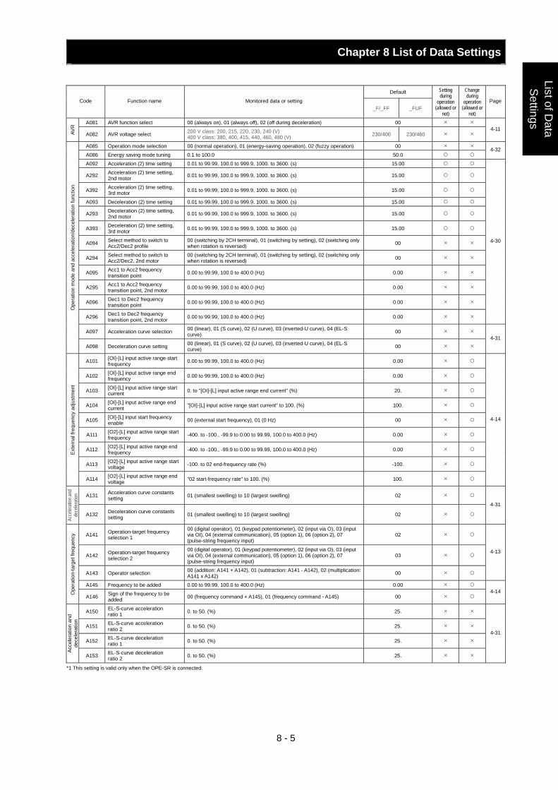
Chapter 8 List of Data Settings
8 - 5
List of Data
Settings
Default Code Function name Monitored data or setting
_F/_FF _FUF
Setting during
operation (allowed or
not)
Change during
operation (allowed or
not)
Page
A081 AVR function select 00 (always on), 01 (always off), 02 (off during deceleration) 00
AVR
A082 AVR voltage select 200 V class: 200, 215, 220, 230, 240 (V) 400 V class: 380, 400, 415, 440, 460, 480 (V) 230/400 230/460
4-11
A085 Operation mode selection 00 (normal operation), 01 (energy-saving operation), 02 (fuzzy operation) 00
A086 Energy saving mode tuning 0.1 to 100.0 50.0 4-32
A092 Acceleration (2) time setting 0.01 to 99.99, 100.0 to 999.9, 1000. to 3600. (s) 15.00
A292 Acceleration (2) time setting, 2nd motor 0.01 to 99.99, 100.0 to 999.9, 1000. to 3600. (s) 15.00
A392 Acceleration (2) time setting, 3rd motor 0.01 to 99.99, 100.0 to 999.9, 1000. to 3600. (s) 15.00
A093 Deceleration (2) time setting 0.01 to 99.99, 100.0 to 999.9, 1000. to 3600. (s) 15.00
A293 Deceleration (2) time setting, 2nd motor 0.01 to 99.99, 100.0 to 999.9, 1000. to 3600. (s) 15.00
A393 Deceleration (2) time setting, 3rd motor 0.01 to 99.99, 100.0 to 999.9, 1000. to 3600. (s) 15.00
A094 Select method to switch to Acc2/Dec2 profile
00 (switching by 2CH terminal), 01 (switching by setting), 02 (switching only when rotation is reversed) 00
A294 Select method to switch to Acc2/Dec2, 2nd motor
00 (switching by 2CH terminal), 01 (switching by setting), 02 (switching only when rotation is reversed) 00
A095 Acc1 to Acc2 frequency transition point 0.00 to 99.99, 100.0 to 400.0 (Hz) 0.00
A295 Acc1 to Acc2 frequency transition point, 2nd motor 0.00 to 99.99, 100.0 to 400.0 (Hz) 0.00
A096 Dec1 to Dec2 frequency transition point 0.00 to 99.99, 100.0 to 400.0 (Hz) 0.00
A296 Dec1 to Dec2 frequency transition point, 2nd motor 0.00 to 99.99, 100.0 to 400.0 (Hz) 0.00
4-30
A097 Acceleration curve selection 00 (linear), 01 (S curve), 02 (U curve), 03 (inverted-U curve), 04 (EL-S curve) 00
Ope
ratio
n m
ode
and
acce
lera
tion/
dece
lera
tion
func
tion
A098 Deceleration curve setting 00 (linear), 01 (S curve), 02 (U curve), 03 (inverted-U curve), 04 (EL-S curve) 00
4-31
A101 [OI]-[L] input active range start frequency 0.00 to 99.99, 100.0 to 400.0 (Hz) 0.00
A102 [OI]-[L] input active range end frequency 0.00 to 99.99, 100.0 to 400.0 (Hz) 0.00
A103 [OI]-[L] input active range start current 0. to "[OI]-[L] input active range end current" (%) 20.
A104 [OI]-[L] input active range end current "[OI]-[L] input active range start current" to 100. (%) 100.
A105 [OI]-[L] input start frequency enable 00 (external start frequency), 01 (0 Hz) 00
A111 [O2]-[L] input active range start frequency -400. to -100., -99.9 to 0.00 to 99.99, 100.0 to 400.0 (Hz) 0.00
A112 [O2]-[L] input active range end frequency -400. to -100., -99.9 to 0.00 to 99.99, 100.0 to 400.0 (Hz) 0.00
A113 [O2]-[L] input active range start voltage -100. to 02 end-frequency rate (%) -100.
Exte
rnal
freq
uenc
y ad
just
men
t
A114 [O2]-[L] input active range end voltage "02 start-frequency rate" to 100. (%) 100.
4-14
A131 Acceleration curve constants setting 01 (smallest swelling) to 10 (largest swelling) 02
Acce
lerati
on an
d de
celer
ation
A132 Deceleration curve constants setting 01 (smallest swelling) to 10 (largest swelling) 02
4-31
A141 Operation-target frequency selection 1
00 (digital operator), 01 (keypad potentiometer), 02 (input via O), 03 (input via OI), 04 (external communication), 05 (option 1), 06 (option 2), 07 (pulse-string frequency input)
02
A142 Operation-target frequency selection 2
00 (digital operator), 01 (keypad potentiometer), 02 (input via O), 03 (input via OI), 04 (external communication), 05 (option 1), 06 (option 2), 07 (pulse-string frequency input)
03
A143 Operator selection 00 (addition: A141 + A142), 01 (subtraction: A141 - A142), 02 (multiplication: A141 x A142) 00
4-13
A145 Frequency to be added 0.00 to 99.99, 100.0 to 400.0 (Hz) 0.00
Ope
ratio
n-ta
rget
freq
uenc
y
A146 Sign of the frequency to be added 00 (frequency command + A145), 01 (frequency command - A145) 00
4-14
A150 EL-S-curve acceleration ratio 1 0. to 50. (%) 25.
A151 EL-S-curve acceleration ratio 2 0. to 50. (%) 25.
A152 EL-S-curve deceleration ratio 1 0. to 50. (%) 25.
Acce
lera
tion
and
dece
lera
tion
A153 EL-S-curve deceleration ratio 2 0. to 50. (%) 25.
4-31
*1 This setting is valid only when the OPE-SR is connected.
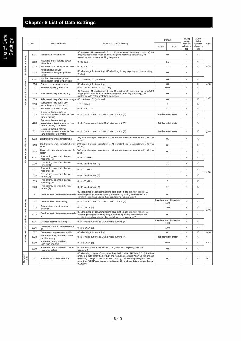
Chapter 8 List of Data Settings
8 - 6
List
of D
ata
Set
tings
Default Code Function name Monitored data or setting
_F/_FF _FUF
Setting during
operation (allowed or
not)
Change during
operation (allowed or
not)
Page
b001 Selection of restart mode 00 (tripping), 01 (starting with 0 Hz), 02 (starting with matching frequency), 03 (tripping after deceleration and stopping with matching frequency), 04 (restarting with active matching frequency)
00
b002 Allowable under-voltage power failure time 0.3 to 25.0 (s) 1.0
b003 Retry wait time before motor restart 0.3 to 100.0 (s) 1.0
b004 Instantaneous power failure/under-voltage trip alarm enable
00 (disabling), 01 (enabling), 02 (disabling during stopping and decelerating to stop) 00
b005 Number of restarts on power failure/under-voltage trip events 00 (16 times), 01 (unlimited) 00
4-33
b006 Phase loss detection enable 00 (disabling), 01 (enabling) 00 4-36b007 Restart frequency threshold 0.00 to 99.99, 100.0 to 400.0 (Hz) 0.00
b008 Selection of retry after tripping 00 (tripping), 01 (starting with 0 Hz), 02 (starting with matching frequency), 03 (tripping after deceleration and stopping with matching frequency), 04 (restarting with active matching frequency)
00
b009 Selection of retry after undervoltage 00 (16 times), 01 (unlimited) 00
b010 Selection of retry count after overvoltage or overcurrent 1 to 3 (times) 3 R
esta
rt af
ter i
nsta
ntan
eous
pow
er fa
ilure
or t
rippi
ng
b011 Retry wait time after tripping 0.3 to 100.0 (s) 1.0
4-33
b012 Electronic thermal setting (calculated within the inverter from current output)
0.20 x "rated current" to 1.00 x "rated current" (A) Rated current of inverter
b212 Electronic thermal setting (calculated within the inverter from current output), 2nd motor
0.20 x "rated current" to 1.00 x "rated current" (A) Rated current of inverter
b312 Electronic thermal setting (calculated within the inverter from current output), 3rd motor
0.20 x "rated current" to 1.00 x "rated current" (A) Rated current of inverter
b013 Electronic thermal characteristic 00 (reduced-torque characteristic), 01 (constant-torque characteristic), 02 (free setting) 01
b213 Electronic thermal characteristic, 2nd motor
00 (reduced-torque characteristic), 01 (constant-torque characteristic), 02 (free setting) 01
b313 Electronic thermal characteristic, 3rd motor
00 (reduced-torque characteristic), 01 (constant-torque characteristic), 02 (free setting) 01
4-37
b015 Free setting, electronic thermal frequency (1) 0. to 400. (Hz) 0.
b016 Free setting, electronic thermal current (1) 0.0 to rated current (A) 0.0
b017 Free setting, electronic thermal frequency (2) 0. to 400. (Hz) 0.
b018 Free setting, electronic thermal current (2) 0.0 to rated current (A) 0.0
b019 Free setting, electronic thermal frequency (3) 0. to 400. (Hz) 0.
Elec
troni
c th
erm
al fu
nctio
n
b020 Free setting, electronic thermal current (3) 0.0 to rated current (A) 0.0
4-38
b021 Overload restriction operation mode 00 (disabling), 01 (enabling during acceleration and constant speed), 02 (enabling during constant speed), 03 (enabling during acceleration and constant speed (increasing the speed during regeneration))
01
b022 Overload restriction setting 0.20 x "rated current" to 1.50 x "rated current" (A) Rated current of inverter x 1.20
b023 Deceleration rate at overload restriction 0.10 to 30.00 (s) 1.00
b024 Overload restriction operation mode (2)
00 (disabling), 01 (enabling during acceleration and constant speed), 02 (enabling during constant speed), 03 (enabling during acceleration and constant speed (increasing the speed during regeneration))
01
b025 Overload restriction setting (2) 0.20 x "rated current" to 1.50 x "rated current" (A) Rated current of inverter x 1.20
b026 Deceleration rate at overload restriction (2) 0.10 to 30.00 (s) 1.00
4-39
b027 Overcurrent suppression enable 00 (disabling), 01 (enabling) 01 4-40
b028 Active frequency matching, scan start frequency 0.20 x "rated current" to 1.50 x "rated current" (A) Rated current of inverter
b029 Active frequency matching, scan-time constant 0.10 to 30.00 (s) 0.50 O
verlo
ad re
stric
tion
and
over
curre
nt re
stra
int
b030 Active frequency matching, restart frequency select
00 (frequency at the last shutoff), 01 (maximum frequency), 02 (set frequency) 00
4-33
Softw
are
lock
b031 Software lock mode selection
00 (disabling change of data other than "b031" when SFT is on), 01 (disabling change of data other than "b031" and frequency settings when SFT is on), 02 (disabling change of data other than "b031"), 03 (disabling change of data other than "b031" and frequency settings), 10 (enabling data changes during operation)
01 4-51
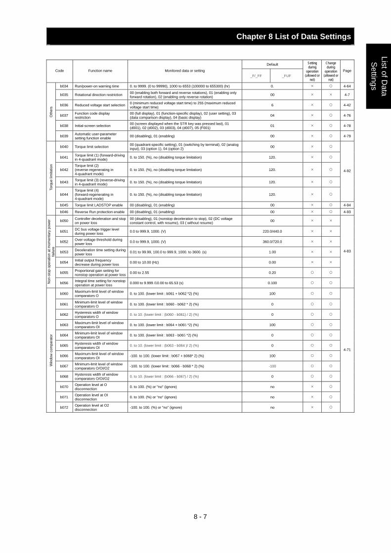
Chapter 8 List of Data Settings
8 - 7
List of Data
Settings
Default Code Function name Monitored data or setting
_F/_FF _FUF
Setting during
operation (allowed or
not)
Change during
operation (allowed or
not)
Page
b034 Run/power-on warning time 0. to 9999. (0 to 99990), 1000 to 6553 (100000 to 655300) (hr) 0. 4-64
b035 Rotational direction restriction 00 (enabling both forward and reverse rotations), 01 (enabling only forward rotation), 02 (enabling only reverse rotation) 00 4-7
b036 Reduced voltage start selection 0 (minimum reduced voltage start time) to 255 (maximum reduced voltage start time) 6 4-42
b037 Function code display restriction
00 (full display), 01 (function-specific display), 02 (user setting), 03 (data comparison display), 04 (basic display) 04 4-76
b038 Initial-screen selection 00 (screen displayed when the STR key was pressed last), 01 (d001), 02 (d002), 03 (d003), 04 (d007), 05 (F001) 01 4-78
Oth
ers
b039 Automatic user-parameter setting function enable 00 (disabling), 01 (enabling) 00 4-79
b040 Torque limit selection 00 (quadrant-specific setting), 01 (switching by terminal), 02 (analog input), 03 (option 1), 04 (option 2) 00
b041 Torque limit (1) (forward-driving in 4-quadrant mode) 0. to 150. (%), no (disabling torque limitation) 120.
b042 Torque limit (2) (reverse-regenerating in 4-quadrant mode)
0. to 150. (%), no (disabling torque limitation) 120.
b043 Torque limit (3) (reverse-driving in 4-quadrant mode) 0. to 150. (%), no (disabling torque limitation) 120.
b044 Torque limit (4) (forward-regenerating in 4-quadrant mode)
0. to 150. (%), no (disabling torque limitation) 120.
4-92
b045 Torque limit LADSTOP enable 00 (disabling), 01 (enabling) 00 4-94
Torq
ue li
mita
tion
b046 Reverse Run protection enable 00 (disabling), 01 (enabling) 00 4-93
b050 Controller deceleration and stop on power loss
00 (disabling), 01 (nonstop deceleration to stop), 02 (DC voltage constant control, with resume), 03 ( without resume) 00
b051 DC bus voltage trigger level during power loss 0.0 to 999.9, 1000. (V) 220.0/440.0
b052 Over-voltage threshold during power loss 0.0 to 999.9, 1000. (V) 360.0/720.0
b053 Deceleration time setting during power loss 0.01 to 99.99, 100.0 to 999.9, 1000. to 3600. (s) 1.00
b054 Initial output frequency decrease during power loss 0.00 to 10.00 (Hz) 0.00
b055 Proportional gain setting for nonstop operation at power loss 0.00 to 2.55 0.20
Non
-sto
p op
erat
ion
at m
omen
tary
pow
er
failu
re
b056 Integral time setting for nonstop operation at power loss 0.000 to 9.999 /10.00 to 65.53 (s) 0.100
4-83
b060 Maximum-limit level of window comparators O 0. to 100. (lower limit : b061 + b062 *2) (%) 100
b061 Minimum-limit level of window comparators O 0. to 100. (lower limit : b060 - b062 * 2) (%) 0
b062 Hysteresis width of window comparators O 0. to 10. (lower limit : (b060 - b061) / 2) (%) 0
b063 Maximum-limit level of window comparators OI 0. to 100. (lower limit : b064 + b065 *2) (%) 100
b064 Minimum-limit level of window comparators OI 0. to 100. (lower limit : b063 - b065 *2) (%) 0
b065 Hysteresis width of window comparators OI 0. to 10. (lower limit : (b063 - b064 )/ 2) (%) 0
b066 Maximum-limit level of window comparators OI -100. to 100. (lower limit : b067 + b068* 2) (%) 100
b067 Minimum-limit level of window comparators O/OI/O2 -100. to 100. (lower limit : b066 - b068 * 2) (%) -100
b068 Hysteresis width of window comparators O/OI/O2 0. to 10. (lower limit : (b066 - b067) / 2) (%) 0
b070 Operation level at O disconnection 0. to 100. (%) or "no" (ignore) no
b071 Operation level at OI disconnection 0. to 100. (%) or "no" (ignore) no
Win
dow
com
para
tor
b072 Operation level at O2 disconnection -100. to 100. (%) or "no" (ignore) no
4-71
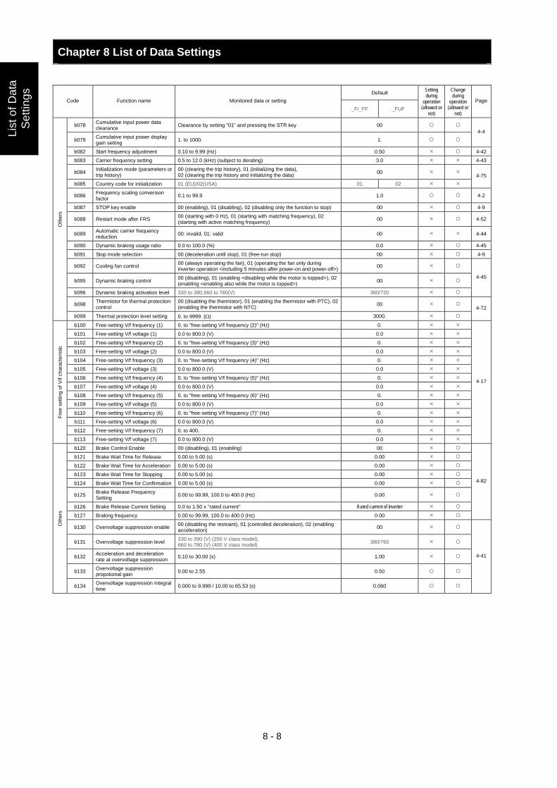
Chapter 8 List of Data Settings
8 - 8
List
of D
ata
Set
tings
Default Code Function name Monitored data or setting
_F/_FF _FUF
Setting during
operation (allowed or
not)
Change during
operation (allowed or
not)
Page
b078 Cumulative input power data clearance Clearance by setting "01" and pressing the STR key 00
b079 Cumulative input power display gain setting 1. to 1000. 1.
4-4
b082 Start frequency adjustment 0.10 to 9.99 (Hz) 0.50 4-42
b083 Carrier frequency setting 0.5 to 12.0 (kHz) (subject to derating) 3.0 4-43
b084 Initialization mode (parameters or trip history)
00 (clearing the trip history), 01 (initializing the data), 02 (clearing the trip history and initializing the data) 00
b085 Country code for initialization 01 (EU)/02(USA) 01 02 4-75
b086 Frequency scaling conversion factor 0.1 to 99.9 1.0 4-2
b087 STOP key enable 00 (enabling), 01 (disabling), 02 (disabling only the function to stop) 00 4-9
b088 Restart mode after FRS 00 (starting with 0 Hz), 01 (starting with matching frequency), 02 (starting with active matching frequency) 00 4-52
b089 Automatic carrier frequency reduction 00: invalid, 01: valid 00 4-44
b090 Dynamic braking usage ratio 0.0 to 100.0 (%) 0.0 4-45
b091 Stop mode selection 00 (deceleration until stop), 01 (free-run stop) 00 4-9
b092 Cooling fan control 00 (always operating the fan), 01 (operating the fan only during inverter operation <including 5 minutes after power-on and power-off>) 00
b095 Dynamic braking control 00 (disabling), 01 (enabling <disabling while the motor is topped>), 02 (enabling <enabling also while the motor is topped>) 00
b096 Dynamic braking activation level 330 to 380,660 to 760(V) 360/720
4-45
b098 Thermistor for thermal protection control
00 (disabling the thermistor), 01 (enabling the thermistor with PTC), 02 (enabling the thermistor with NTC) 00
Oth
ers
b099 Thermal protection level setting 0. to 9999. (Ω) 3000. 4-72
b100 Free-setting V/f frequency (1) 0. to "free-setting V/f frequency (2)" (Hz) 0.
b101 Free-setting V/f voltage (1) 0.0 to 800.0 (V) 0.0
b102 Free-setting V/f frequency (2) 0. to "free-setting V/f frequency (3)" (Hz) 0.
b103 Free-setting V/f voltage (2) 0.0 to 800.0 (V) 0.0
b104 Free-setting V/f frequency (3) 0. to "free-setting V/f frequency (4)" (Hz) 0.
b105 Free-setting V/f voltage (3) 0.0 to 800.0 (V) 0.0
b106 Free-setting V/f frequency (4) 0. to "free-setting V/f frequency (5)" (Hz) 0.
b107 Free-setting V/f voltage (4) 0.0 to 800.0 (V) 0.0
b108 Free-setting V/f frequency (5) 0. to "free-setting V/f frequency (6)" (Hz) 0.
b109 Free-setting V/f voltage (5) 0.0 to 800.0 (V) 0.0
b110 Free-setting V/f frequency (6) 0. to "free-setting V/f frequency (7)" (Hz) 0.
b111 Free-setting V/f voltage (6) 0.0 to 800.0 (V) 0.0
b112 Free-setting V/f frequency (7) 0. to 400. 0.
Free
set
ting
of V
/f ch
arac
teris
tic
b113 Free-setting V/f voltage (7) 0.0 to 800.0 (V) 0.0
4-17
b120 Brake Control Enable 00 (disabling), 01 (enabling) 00
b121 Brake Wait Time for Release 0.00 to 5.00 (s) 0.00
b122 Brake Wait Time for Acceleration 0.00 to 5.00 (s) 0.00
b123 Brake Wait Time for Stopping 0.00 to 5.00 (s) 0.00
b124 Brake Wait Time for Confirmation 0.00 to 5.00 (s) 0.00
b125 Brake Release Frequency Setting 0.00 to 99.99, 100.0 to 400.0 (Hz) 0.00
b126 Brake Release Current Setting 0.0 to 1.50 x "rated current" Rated current of inverter
b127 Braking frequency 0.00 to 99.99, 100.0 to 400.0 (Hz) 0.00
4-82
b130 Overvoltage suppression enable 00 (disabling the restraint), 01 (controlled deceleration), 02 (enabling acceleration) 00
b131 Overvoltage suppression level 330 to 390 (V) (200 V class model), 660 to 780 (V) (400 V class model) 380/760
b132 Acceleration and deceleration rate at overvoltage suppression 0.10 to 30.00 (s) 1.00
b133 Overvoltage suppression propotional gain 0.00 to 2.55 0.50
Oth
ers
b134 Overvoltage suppression Integral time 0.000 to 9.999 / 10.00 to 65.53 (s) 0.060
4-41
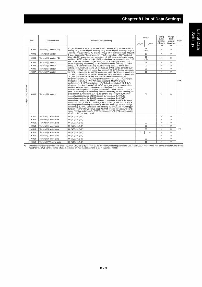
Chapter 8 List of Data Settings
8 - 9
List of Data
Settings
Default Code Function name Monitored data or setting
_F/_FF _FUF
Setting during
operation (allowed or
not)
Change during
operation (allowed or
not)
Page
C001 Terminal [1] function (*2) 18 (*2)
C002 Terminal [2] function 16
C003 Terminal [3] function (*2) 06 (*2)
C004 Terminal [4] function 11
C005 Terminal [5] function 09
C006 Terminal [6] function 03
C007 Terminal [7] function 02
C008 Terminal [8] function
01 (RV: Reverse RUN), 02 (CF1: Multispeed 1 setting), 03 (CF2: Multispeed 2 setting), 04 (CF3: Multispeed 3 setting), 05 (CF4: Multispeed 4 setting), 06 (JG: Jogging), 07 (DB: external DC braking), 08 (SET: Set 2nd motor data), 09 (2CH: 2-stage acceleration/deceleration), 11 (FRS: free-run stop), 12 (EXT: external trip), 13 (USP: unattended start protection), 14: (CS: commercial power source enable), 15 (SFT: software lock), 16 (AT: analog input voltage/current select), 17 (SET3: 3rd motor control), 18 (RS: reset), 20 (STA: starting by 3-wire input), 21 (STP: stopping by 3-wire input), 22 (F/R: forward/reverse switching by 3-wire input), 23 (PID: PID disable), 24 (PIDC: PID reset), 26 (CAS: control gain setting), 27 (UP: remote control UP function), 28 (DWN: remote control DOWN function), 29 (DWN: remote control data clearing), 31 (OPE: forcible operation), 32 (SF1: multispeed bit 1), 33 (SF2: multispeed bit 2), 34 (SF3: multispeed bit 3), 35 (SF4: multispeed bit 4), 36 (SF5: multispeed bit 5), 37 (SF6: multispeed bit 6), 38 (SF7: multispeed bit 7), 39 (OLR: overload restriction selection), 40 (TL: torque limit enable), 41 (TRQ1: torque limit selection bit 1), 42 (TRQ2: torque limit selection bit 2), 43 (PPI: P/PI mode selection), 44 (BOK: braking confirmation), 45 (ORT: orientation), 46 (LAC: LAD cancellation), 47 (PCLR: clearance of position deviation), 48 (STAT: pulse train position command input enable), 50 (ADD: trigger for frequency addition [A145]), 51 (F-TM: forcible-terminal operation), 52 (ATR: permission of torque command input), 53 (KHC: cumulative power clearance), 54 (SON: servo-on), 55 (FOC: forcing), 56 (MI1: general-purpose input 1), 57 (MI2: general-purpose input 2), 58 (MI3: general-purpose input 3), 59 (MI4: general-purpose input 4), 60 (MI5: general-purpose input 5), 61 (MI6: general-purpose input 6), 62 (MI7: general-purpose input 7), 63 (MI8: general-purpose input 8), 65 (AHD: analog command holding), 66 (CP1: multistage position settings selection 1 ), 67 (CP2: multistage position settings selection 2), 68 (CP3: multistage position settings selection 3), 69 (ORL: Zero-return limit function), 70 (ORG: Zero-return trigger function), 71 (FOT: forward drive stop), 72 (ROT: reverse drive stop), 73 (SPD: speed / position switching), 74 (PCNT: pulse counter), 75 (PCC: pulse counter clear), no (NO: no assignment)
01
4-46
C011 Terminal [1] active state 00 (NO) / 01 (NC) 00
C012 Terminal [2] active state 00 (NO) / 01 (NC) 00
C013 Terminal [3] active state 00 (NO) / 01 (NC) 00
C014 Terminal [4] active state 00 (NO) / 01 (NC) 00
C015 Terminal [5] active state 00 (NO) / 01 (NC) 00
C016 Terminal [6] active state 00 (NO) / 01 (NC) 00 01
C017 Terminal [7] active state 00 (NO) / 01 (NC) 00
C018 Terminal [8] active state 00 (NO) / 01 (NC) 00
Inte
lligen
t inp
ut te
rmin
als
C019 Terminal [FW] active state 00 (NO) / 01 (NC) 00
4-47
*2 When the emergency stop function is enabled (SW1 = ON), "18" (RS) and "64" (EMR) are forcibly written to parameters "C001" and "C003", respectively. (You cannot arbitrarily write "64" to "C001".) If the SW1 signal is turned off and then turned on, "no" (no assignment) is set in parameter "C003".
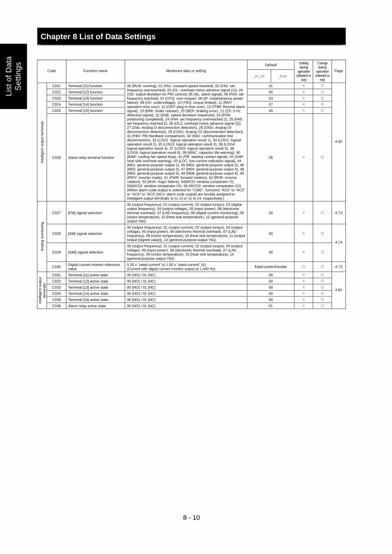
Chapter 8 List of Data Settings
8 - 10
List
of D
ata
Set
tings
Default Code Function name Monitored data or setting
_F/_FF _FUF
Setting during
operation (allowed or
not)
Change during
operation (allowed or
not)
Page
C021 Terminal [11] function 01
C022 Terminal [12] function 00
C023 Terminal [13] function 03
C024 Terminal [14] function 07
C025 Terminal [15] function 40
Inte
lligen
t out
put t
erm
inal
s
C026 Alarm relay terminal function
00 (RUN: running), 01 (FA1: constant-speed reached), 02 (FA2: set frequency overreached), 03 (OL: overload notice advance signal (1)), 04 (OD: output deviation for PID control), 05 (AL: alarm signal), 06 (FA3: set frequency reached), 07 (OTQ: over-torque), 08 (IP: instantaneous power failure), 09 (UV: undervoltage), 10 (TRQ: torque limited), 11 (RNT: operation time over), 12 (ONT: plug-in time over), 13 (THM: thermal alarm signal), 19 (BRK: brake release), 20 (BER: braking error), 21 (ZS: 0 Hz detection signal), 22 (DSE: speed deviation maximum), 23 (POK: positioning completed), 24 (FA4: set frequency overreached 2), 25 (FA5: set frequency reached 2), 26 (OL2: overload notice advance signal (2)), 27 (Odc: Analog O disconnection detection), 28 (OIDc: Analog OI disconnection detection), 29 (O2Dc: Analog O2 disconnection detection), 31 (FBV: PID feedback comparison), 32 (NDc: communication line disconnection), 33 (LOG1: logical operation result 1), 34 (LOG2: logical operation result 2), 35 (LOG3: logical operation result 3), 36 (LOG4: logical operation result 4), 37 (LOG5: logical operation result 5), 38 (LOG6: logical operation result 6), 39 (WAC: capacitor life warning), 40 (WAF: cooling-fan speed drop), 41 (FR: starting contact signal), 42 (OHF: heat sink overheat warning), 43 (LOC: low-current indication signal), 44 (M01: general-purpose output 1), 45 (M02: general-purpose output 2), 46 (M03: general-purpose output 3), 47 (M04: general-purpose output 4), 48 (M05: general-purpose output 5), 49 (M06: general-purpose output 6), 50 (IRDY: inverter ready), 51 (FWR: forward rotation), 52 (RVR: reverse rotation), 53 (MJA: major failure), 54(WCO: window comparator O), 55(WCOI: window comparator OI), 56 (WCO2: window comparator O2) (When alarm code output is selected for "C062", functions "AC0" to "AC2" or "AC0" to "AC3" [ACn: alarm code output] are forcibly assigned to intelligent output terminals 11 to 13 or 11 to 14, respectively.)
05
4-60
C027 [FM] siginal selection
00 (output frequency), 01 (output current), 02 (output torque), 03 (digital output frequency), 04 (output voltage), 05 (input power), 06 (electronic thermal overload), 07 (LAD frequency), 08 (digital current monitoring), 09 (motor temperature), 10 (heat sink temperature), 12 (general-purpose output YA0)
00 4-73
C028 [AM] siginal selection
00 (output frequency), 01 (output current), 02 (output torque), 04 (output voltage), 05 (input power), 06 (electronic thermal overload), 07 (LAD frequency), 09 (motor temperature), 10 (heat sink temperature), 11 (output torque [signed value]), 13 (general-purpose output YA1)
00
C029 [AMI] siginal selection
00 (output frequency), 01 (output current), 02 (output torque), 04 (output voltage), 05 (input power), 06 (electronic thermal overload), 07 (LAD frequency), 09 (motor temperature), 10 (heat sink temperature), 14 (general-purpose output YA2)
00
4-74
Anal
og m
onito
ring
C030 Digital current monitor reference value
0.20 x "rated current" to 1.50 x "rated current" (A) (Current with digital current monitor output at 1,440 Hz) Rated current of inverter 4-73
C031 Terminal [11] active state 00 (NO) / 01 (NC) 00
C032 Terminal [12] active state 00 (NO) / 01 (NC) 00
C033 Terminal [13] active state 00 (NO) / 01 (NC) 00
C034 Terminal [14] active state 00 (NO) / 01 (NC) 00
C035 Terminal [15] active state 00 (NO) / 01 (NC) 00
Inte
lligen
t out
put
term
inal
s
C036 Alarm relay active state 00 (NO) / 01 (NC) 01
4-61
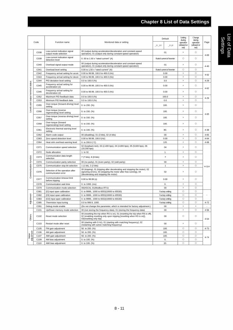
Chapter 8 List of Data Settings
8 - 11
List of Data
Settings
Default Code Function name Monitored data or setting
_F/_FF _FUF
Setting during
operation (allowed or
not)
Change during
operation (allowed or
not)
Page
C038 Low-current indication signal output mode selection
00 (output during acceleration/deceleration and constant-speed operation), 01 (output only during constant-speed operation) 01
C039 Low-current indication signal detection level 0. 00 to 1.50 x "rated current" (A) Rated current of inverter
4-69
C040 Overload signal output mode 00 (output during acceleration/deceleration and constant-speed operation), 01 (output only during constant-speed operation) 01
C041 Overload level setting 0.00 to 1.50 x "rated current" (A) Rated current of inverter 4-40
C042 Frequency arrival setting for accel. 0.00 to 99.99, 100.0 to 400.0 (Hz) 0.00
C043 Frequency arrival setting for decel. 0.00 to 99.99, 100.0 to 400.0 (Hz) 0.00 4-62
C044 PID deviation level setting 0.0 to 100.0 (%) 3.0 4-29
C045 Frequency arrival setting for acceleration (2) 0.00 to 99.99, 100.0 to 400.0 (Hz) 0.00
C046 Frequency arrival setting for deceleration (2) 0.00 to 99.99, 100.0 to 400.0 (Hz) 0.00
4-62
C052 Maximum PID feedback data 0.0 to 100.0 (%) 100.0
C053 Minimum PID feedback data 0.0 to 100.0 (%) 0.0 4-26
C055 Over-torque (forward-driving) level setting 0. to 150. (%) 100.
C056 Over-torque (reverse regenerating) level setting 0. to 150. (%) 100.
C057 Over-torque (reverse driving) level setting 0. to 150. (%) 100.
C058 Over-torque (forward regenerating) level setting 0. to 150. (%) 100.
4-65
C061 Electronic thermal warning level setting 0. to 100. (%) 80. 4-38
C062 Alarm code output 00 (disabling), 01 (3 bits), 02 (4 bits) 00 4-65
C063 Zero speed detection level 0.00 to 99.99, 100.0 (Hz) 0.00 4-64
Leve
ls a
nd o
utpu
t ter
min
al s
tatu
s
C064 Heat sink overheat warning level 0. to 200.0 (°C) 120. 4-68
C071 Communication speed selection 02 (loopback test), 03 (2,400 bps), 04 (4,800 bps), 05 (9,600 bps), 06 (19,200 bps) 04
C072 Node allocation 1. to 32. 1.
C073 Communication data length selection 7 (7 bits), 8 (8 bits) 7
C074 Communication parity selection 00 (no parity), 01 (even parity), 02 (odd parity) 00
C075 Communication stop bit selection 1 (1 bit), 2 (2 bits) 1
C076 Selection of the operation after communication error
00 (tripping), 01 (tripping after decelerating and stopping the motor), 02 (ignoring errors), 03 (stopping the motor after free-running), 04 (decelerating and stopping the motor)
02
C077 Communication timeout limit before tripping 0.00 to 99.99 (s) 0.00
C078 Communication wait time 0. to 1000. (ms) 0.
Com
mun
icat
ion
func
tion
C079 Communication mode selection 00(ASCII), 01(Modbus-RTU) 00
4-114
C081 [O] input span calibration 0. to 9999., 1000 to 6553(10000 to 65530) Factory setting
C082 [OI] input span calibration 0. to 9999., 1000 to 6553(10000 to 65530) Factory setting
C083 [O2] input span calibration 0. to 9999., 1000 to 6553(10000 to 65530) Factory setting
−
C085 Thermistor input tuning 0.0 to 999.9, 1000. Factory setting 4-72Adju
stm
ent
C091 Debug mode enable (Do not change this parameter, which is intended for factory adjustment.) 00 −
C101 Up/Down memory mode selection 00 (not storing the frequency data), 01 (storing the frequency data) 00 4-56
C102 Reset mode selection 00 (resetting the trip when RS is on), 01 (resetting the trip when RS is off), 02 (enabling resetting only upon tripping [resetting when RS is on]), 03(resetting only trip)
00
Oth
ers
C103 Restart mode after reset 00 (starting with 0 Hz), 01 (starting with matching frequency), 02 (restarting with active matching frequency) 00
4-54
C105 FM gain adjustment 50. to 200. (%) 100. 4-73
C106 AM gain adjustment 50. to 200. (%) 100.
C107 AMI gain adjustment 50. to 200. (%) 100.
C109 AM bias adjustment 0. to 100. (%) 0.
Met
er
adju
stm
ent
C110 AMI bias adjustment 0. to 100. (%) 20.
4-74
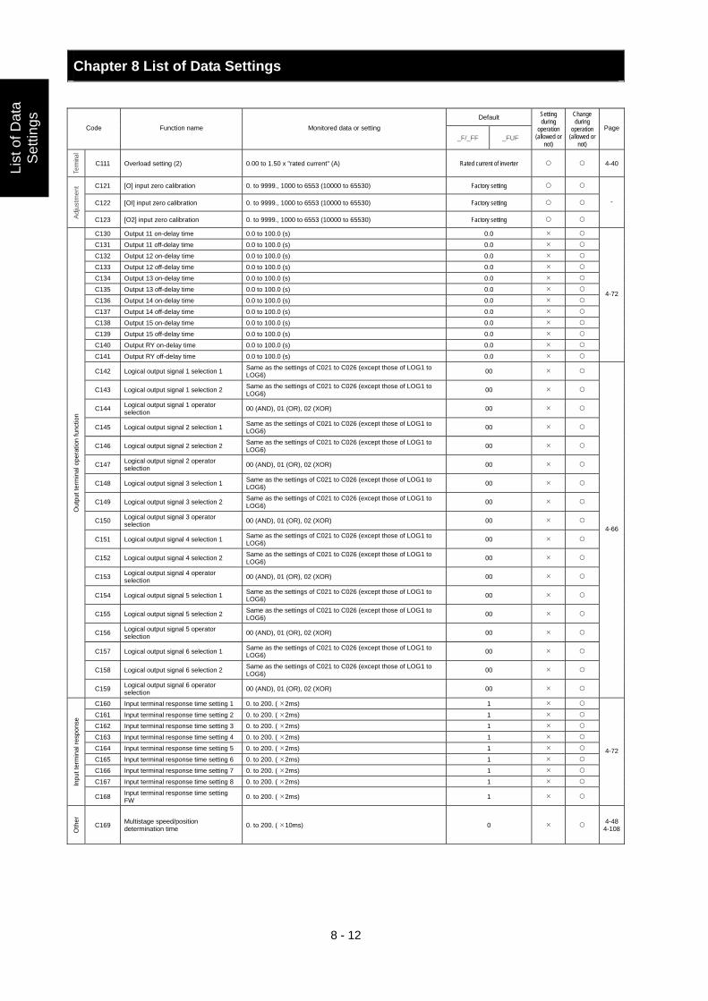
Chapter 8 List of Data Settings
8 - 12
List
of D
ata
Set
tings
Default Code Function name Monitored data or setting
_F/_FF _FUF
Setting during
operation (allowed or
not)
Change during
operation (allowed or
not)
Page
Term
inal
C111 Overload setting (2) 0.00 to 1.50 x "rated current" (A) Rated current of inverter 4-40
C121 [O] input zero calibration 0. to 9999., 1000 to 6553 (10000 to 65530) Factory setting
C122 [OI] input zero calibration 0. to 9999., 1000 to 6553 (10000 to 65530) Factory setting
Adju
stm
ent
C123 [O2] input zero calibration 0. to 9999., 1000 to 6553 (10000 to 65530) Factory setting
-
C130 Output 11 on-delay time 0.0 to 100.0 (s) 0.0
C131 Output 11 off-delay time 0.0 to 100.0 (s) 0.0
C132 Output 12 on-delay time 0.0 to 100.0 (s) 0.0
C133 Output 12 off-delay time 0.0 to 100.0 (s) 0.0
C134 Output 13 on-delay time 0.0 to 100.0 (s) 0.0
C135 Output 13 off-delay time 0.0 to 100.0 (s) 0.0
C136 Output 14 on-delay time 0.0 to 100.0 (s) 0.0
C137 Output 14 off-delay time 0.0 to 100.0 (s) 0.0
C138 Output 15 on-delay time 0.0 to 100.0 (s) 0.0
C139 Output 15 off-delay time 0.0 to 100.0 (s) 0.0
C140 Output RY on-delay time 0.0 to 100.0 (s) 0.0
C141 Output RY off-delay time 0.0 to 100.0 (s) 0.0
4-72
C142 Logical output signal 1 selection 1 Same as the settings of C021 to C026 (except those of LOG1 to LOG6) 00
C143 Logical output signal 1 selection 2 Same as the settings of C021 to C026 (except those of LOG1 to LOG6) 00
C144 Logical output signal 1 operator selection 00 (AND), 01 (OR), 02 (XOR) 00
C145 Logical output signal 2 selection 1 Same as the settings of C021 to C026 (except those of LOG1 to LOG6) 00
C146 Logical output signal 2 selection 2 Same as the settings of C021 to C026 (except those of LOG1 to LOG6) 00
C147 Logical output signal 2 operator selection 00 (AND), 01 (OR), 02 (XOR) 00
C148 Logical output signal 3 selection 1 Same as the settings of C021 to C026 (except those of LOG1 to LOG6) 00
C149 Logical output signal 3 selection 2 Same as the settings of C021 to C026 (except those of LOG1 to LOG6) 00
C150 Logical output signal 3 operator selection 00 (AND), 01 (OR), 02 (XOR) 00
C151 Logical output signal 4 selection 1 Same as the settings of C021 to C026 (except those of LOG1 to LOG6) 00
C152 Logical output signal 4 selection 2 Same as the settings of C021 to C026 (except those of LOG1 to LOG6) 00
C153 Logical output signal 4 operator selection 00 (AND), 01 (OR), 02 (XOR) 00
C154 Logical output signal 5 selection 1 Same as the settings of C021 to C026 (except those of LOG1 to LOG6) 00
C155 Logical output signal 5 selection 2 Same as the settings of C021 to C026 (except those of LOG1 to LOG6) 00
C156 Logical output signal 5 operator selection 00 (AND), 01 (OR), 02 (XOR) 00
C157 Logical output signal 6 selection 1 Same as the settings of C021 to C026 (except those of LOG1 to LOG6) 00
C158 Logical output signal 6 selection 2 Same as the settings of C021 to C026 (except those of LOG1 to LOG6) 00
Out
put t
erm
inal
ope
ratio
n fu
nctio
n
C159 Logical output signal 6 operator selection 00 (AND), 01 (OR), 02 (XOR) 00
4-66
C160 Input terminal response time setting 1 0. to 200. ( 2ms) 1
C161 Input terminal response time setting 2 0. to 200. ( 2ms) 1
C162 Input terminal response time setting 3 0. to 200. ( 2ms) 1
C163 Input terminal response time setting 4 0. to 200. ( 2ms) 1
C164 Input terminal response time setting 5 0. to 200. ( 2ms) 1
C165 Input terminal response time setting 6 0. to 200. ( 2ms) 1
C166 Input terminal response time setting 7 0. to 200. ( 2ms) 1
C167 Input terminal response time setting 8 0. to 200. ( 2ms) 1 Inpu
t ter
min
al re
spon
se
C168 Input terminal response time setting FW 0. to 200. ( 2ms) 1
4-72
Oth
er
C169 Multistage speed/position determination time 0. to 200. ( 10ms) 0 4-48
4-108
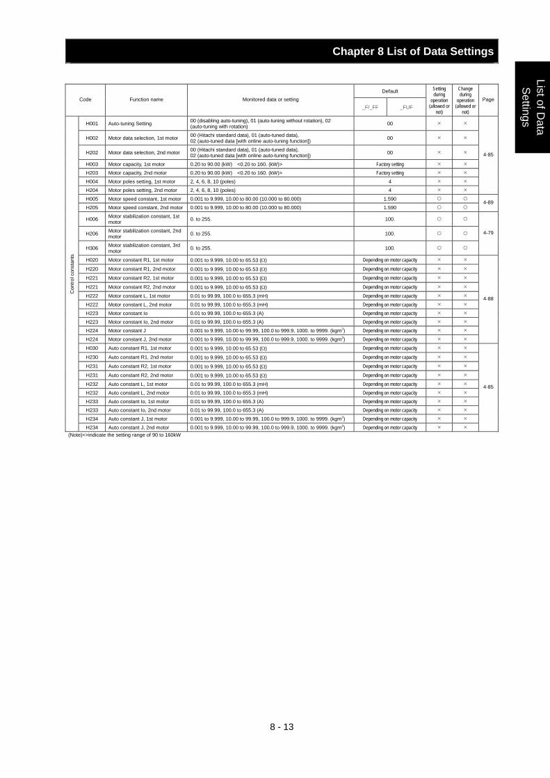
Chapter 8 List of Data Settings
8 - 13
List of Data
Settings
Default Code Function name Monitored data or setting
_F/_FF _FUF
Setting during
operation (allowed or
not)
Change during
operation (allowed or
not)
Page
H001 Auto-tuning Setting 00 (disabling auto-tuning), 01 (auto-tuning without rotation), 02 (auto-tuning with rotation) 00
H002 Motor data selection, 1st motor 00 (Hitachi standard data), 01 (auto-tuned data), 02 (auto-tuned data [with online auto-tuning function]) 00
H202 Motor data selection, 2nd motor 00 (Hitachi standard data), 01 (auto-tuned data), 02 (auto-tuned data [with online auto-tuning function]) 00
H003 Motor capacity, 1st motor 0.20 to 90.00 (kW) <0.20 to 160. (kW)> Factory setting
H203 Motor capacity, 2nd motor 0.20 to 90.00 (kW) <0.20 to 160. (kW)> Factory setting
H004 Motor poles setting, 1st motor 2, 4, 6, 8, 10 (poles) 4
H204 Motor poles setting, 2nd motor 2, 4, 6, 8, 10 (poles) 4
4-85
H005 Motor speed constant, 1st motor 0.001 to 9.999, 10.00 to 80.00 (10.000 to 80.000) 1.590
H205 Motor speed constant, 2nd motor 0.001 to 9.999, 10.00 to 80.00 (10.000 to 80.000) 1.590 4-89
H006 Motor stabilization constant, 1st motor 0. to 255. 100.
H206 Motor stabilization constant, 2nd motor 0. to 255. 100.
H306 Motor stabilization constant, 3rd motor 0. to 255. 100.
4-79
H020 Motor constant R1, 1st motor 0.001 to 9.999, 10.00 to 65.53 (Ω) Depending on motor capacity
H220 Motor constant R1, 2nd motor 0.001 to 9.999, 10.00 to 65.53 (Ω) Depending on motor capacity
H221 Motor constant R2, 1st motor 0.001 to 9.999, 10.00 to 65.53 (Ω) Depending on motor capacity
H221 Motor constant R2, 2nd motor 0.001 to 9.999, 10.00 to 65.53 (Ω) Depending on motor capacity
H222 Motor constant L, 1st motor 0.01 to 99.99, 100.0 to 655.3 (mH) Depending on motor capacity
H222 Motor constant L, 2nd motor 0.01 to 99.99, 100.0 to 655.3 (mH) Depending on motor capacity
H223 Motor constant Io 0.01 to 99.99, 100.0 to 655.3 (A) Depending on motor capacity
H223 Motor constant Io, 2nd motor 0.01 to 99.99, 100.0 to 655.3 (A) Depending on motor capacity
H224 Motor constant J 0.001 to 9.999, 10.00 to 99.99, 100.0 to 999.9, 1000. to 9999. (kgm2) Depending on motor capacity
H224 Motor constant J, 2nd motor 0.001 to 9.999, 10.00 to 99.99, 100.0 to 999.9, 1000. to 9999. (kgm2) Depending on motor capacity
4-88
H030 Auto constant R1, 1st motor 0.001 to 9.999, 10.00 to 65.53 (Ω) Depending on motor capacity
H230 Auto constant R1, 2nd motor 0.001 to 9.999, 10.00 to 65.53 (Ω) Depending on motor capacity
H231 Auto constant R2, 1st motor 0.001 to 9.999, 10.00 to 65.53 (Ω) Depending on motor capacity
H231 Auto constant R2, 2nd motor 0.001 to 9.999, 10.00 to 65.53 (Ω) Depending on motor capacity
H232 Auto constant L, 1st motor 0.01 to 99.99, 100.0 to 655.3 (mH) Depending on motor capacity
H232 Auto constant L, 2nd motor 0.01 to 99.99, 100.0 to 655.3 (mH) Depending on motor capacity
H233 Auto constant Io, 1st motor 0.01 to 99.99, 100.0 to 655.3 (A) Depending on motor capacity
H233 Auto constant Io, 2nd motor 0.01 to 99.99, 100.0 to 655.3 (A) Depending on motor capacity
H234 Auto constant J, 1st motor 0.001 to 9.999, 10.00 to 99.99, 100.0 to 999.9, 1000. to 9999. (kgm2) Depending on motor capacity
Con
trol c
onst
ants
H234 Auto constant J, 2nd motor 0.001 to 9.999, 10.00 to 99.99, 100.0 to 999.9, 1000. to 9999. (kgm2) Depending on motor capacity
4-85
(Note)<>indicate the setting range of 90 to 160kW
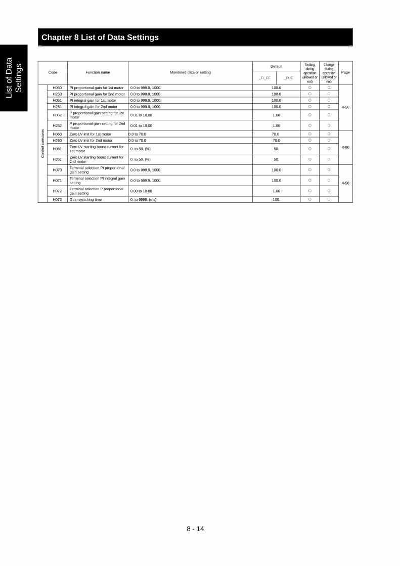
Chapter 8 List of Data Settings
8 - 14
List
of D
ata
Set
tings
Default Code Function name Monitored data or setting
_F/_FF _FUF
Setting during
operation (allowed or
not)
Change during
operation (allowed or
not)
Page
H050 PI proportional gain for 1st motor 0.0 to 999.9, 1000. 100.0
H250 PI proportional gain for 2nd motor 0.0 to 999.9, 1000. 100.0
H051 PI integral gain for 1st motor 0.0 to 999.9, 1000. 100.0
H251 PI integral gain for 2nd motor 0.0 to 999.9, 1000. 100.0
H052 P proportional gain setting for 1st motor 0.01 to 10.00 1.00
H252 P proportional gain setting for 2nd motor 0.01 to 10.00 1.00
4-58
H060 Zero LV lmit for 1st motor 0.0 to 70.0 70.0
H260 Zero LV lmit for 2nd motor 0.0 to 70.0 70.0
H061 Zero LV starting boost current for 1st motor 0. to 50. (%) 50.
H261 Zero LV starting boost current for 2nd motor 0. to 50. (%) 50.
4-90
H070 Terminal selection PI proportional gain setting 0.0 to 999.9, 1000. 100.0
H071 Terminal selection PI integral gain setting 0.0 to 999.9, 1000. 100.0
H072 Terminal selection P proportional gain setting 0.00 to 10.00 1.00
Con
trol c
onst
ants
H073 Gain switching time 0. to 9999. (ms) 100.
4-58
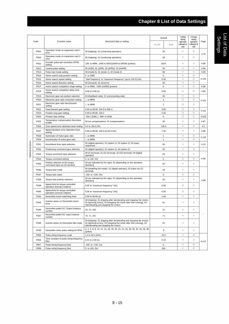
Chapter 8 List of Data Settings
8 - 15
List of Data
Settings
Default Code Function name Monitored data or setting
_F/_FF _FUF
Setting during
operation (allowed or
not)
Change during
operation (allowed or
not)
Page
P001 Operation mode on expansion card 1 error 00 (tripping), 01 (continuing operation) 00
P002 Operation mode on expansion card 2 error 00 (tripping), 01 (continuing operation) 00
4-79
P011 Encoder pulse-per-revolution (PPR) setting 128. to 9999., 1000 to 6553(10000 to 65535) (pulses) 1024. 4-96
P012 Control pulse setting 00 (ASR), 01 (APR), 02 (APR2), 03 (HAPR) 00 4-96
P013 Pulse train mode setting 00 (mode 0), 01 (mode 1), 02 (mode 2) 00 4-99
P014 Home search stop position setting 0. to 4095. 0.
P015 Home search speed setting "start frequency" to "maximum frequency" (up to 120.0) (Hz) 5.00
P016 Home search direction setting 00 (forward), 01 (reverse) 00
4-104
P017 Home search completion range setting 0. to 9999., 1000 (10000) (pulses) 5. 4-99
P018 Home search completion delay time setting 0.00 to 9.99 (s) 0.00 4-99
P019 Electronic gear set position selection 00 (feedback side), 01 (commanding side) 00
P020 Electronic gear ratio numerator setting 1. to 9999. 1.
P021 Electronic gear ratio denominator setting 1. to 9999. 1.
4-101
P022 Feed-forward gain setting 0.00 to 99.99, 100.0 to 655.3 0.00
P023 Position loop gain setting 0.00 to 99.99, 100.0 0.50 4-101
P024 Position bias setting -204 (-2048.) / -999. to 2048. 0. 4-103
P025 Temperature compensation thermistor enable 00 (no compensation), 01 (compensation) 00 4-87
P026 Over-speed error detection level setting 0.0 to 150.0 (%) 135.0 5-5
P027 Speed deviation error detection level setting 0.00 to 99.99, 100.0 to120.0 (Hz) 7.50 4-96
P028 Numerator of motor gear ratio 1. to 9999. 1.
P029 Denominator of motor gear ratio 1. to 9999. 1. 4-103
P031 Accel/decel time input selection 00 (digital operator), 01 (option 1), 02 (option 2), 03 (easy sequence) 00 4-10
P032 Positioning command input selection 00 (digital operator), 01 (option 1), 02 (option 2) 00 −
P033 Torque command input selection 00 (O terminal), 01 (OI terminal), 02 (O2 terminal), 03 (digital operator) 00
P034 Torque command setting 0. to 150. (%) 0.
P035 Polarity selection at the torque command input via O2 terminal
00 (as indicated by the sign), 01 (depending on the operation direction) 00
4-98
P036 Torque bias mode 00 (disabling the mode), 01 (digital operator), 02 (input via O2 terminal) 00
P037 Torque bias value -150. to +150. (%) 0.
P038 Torque bias polarity selection 00 (as indicated by the sign), 01 (depending on the operation direction) 00
P039 Speed limit for torque-controlled operation (forward rotation) 0.00 to "maximum frequency" (Hz) 0.00
P040 Speed limit for torque-controlled operation (reverse rotation) 0.00 to "maximum frequency" (Hz) 0.00
4-98
P044 DeviceNet comm watchdog timer 0.00 to 99.99 (s) 1.00
P045 Inverter action on DeviceNet comm error
00 (tripping), 01 (tripping after decelerating and stopping the motor), 02 (ignoring errors), 03 (stopping the motor after free-running), 04 (decelerating and stopping the motor)
01
P046 DeviceNet polled I/O: Output instance number 20, 21, 100 21
P047 DeviceNet polled I/O: Input instance number 70, 71, 101 71
P048 Inverter action on DeviceNet idle mode 00 (tripping), 01 (tripping after decelerating and stopping the motor), 02 (ignoring errors), 03 (stopping the motor after free-running), 04 (decelerating and stopping the motor)
01
P049 DeviceNet motor poles setting for RPM 0, 2, 4, 6, 8, 10, 12, 14, 16, 18, 20, 22, 24, 26, 28, 30, 32, 34, 36, 38 (poles) 0
−
P055 Pulse-string frequency scale 1.0 to 50.0 (kHz) 25.0
P056 Time constant of pulse-string frequency filter 0.01 to 2.00 (s) 0.10
P057 Pulse-string frequency bias -100. to +100. (%) 0.
Opt
iona
l fun
ctio
ns
P058 Pulse-string frequency limit 0. to 100. (%) 100.
4-112
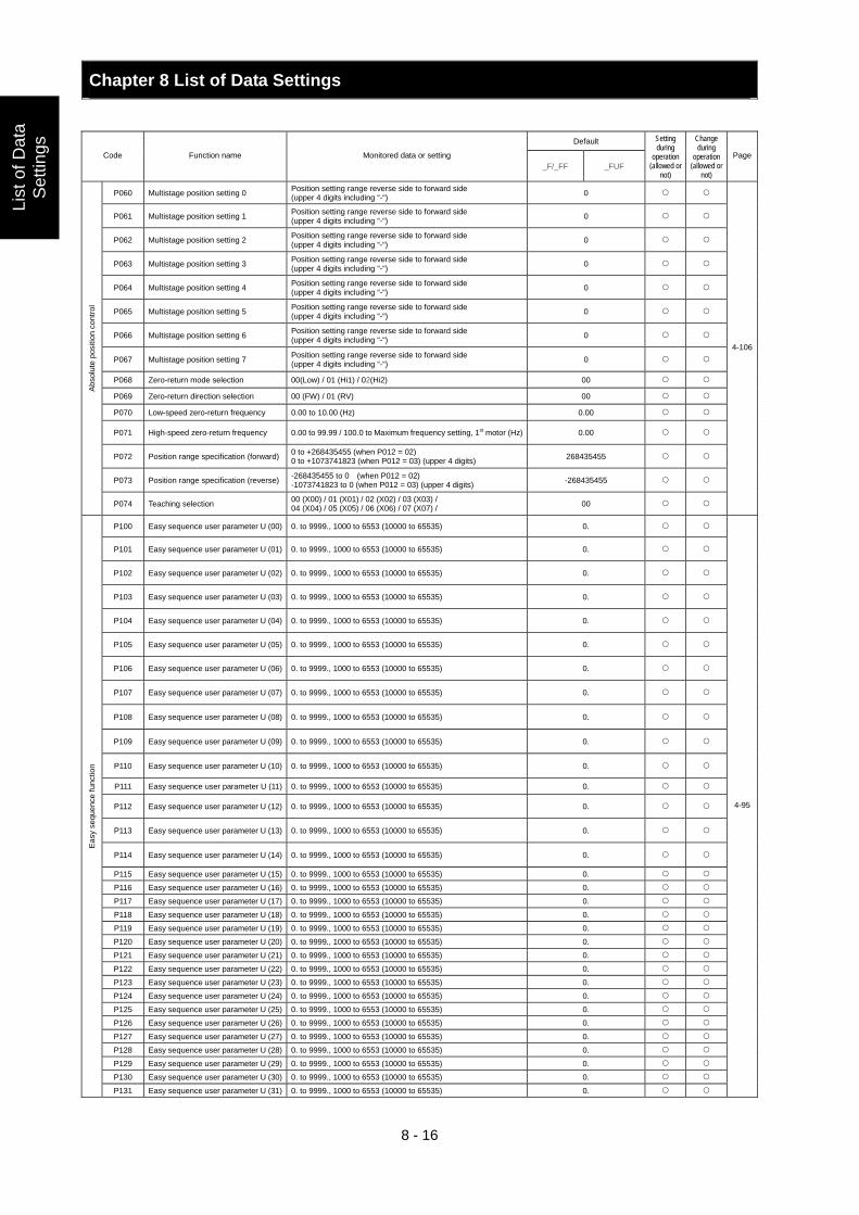
Chapter 8 List of Data Settings
8 - 16
List
of D
ata
Set
tings
Default
Code Function name Monitored data or setting _F/_FF _FUF
Setting during
operation (allowed or
not)
Change during
operation (allowed or
not)
Page
P060 Multistage position setting 0 Position setting range reverse side to forward side (upper 4 digits including “-“) 0
P061 Multistage position setting 1 Position setting range reverse side to forward side (upper 4 digits including “-“) 0
P062 Multistage position setting 2 Position setting range reverse side to forward side (upper 4 digits including “-“) 0
P063 Multistage position setting 3 Position setting range reverse side to forward side (upper 4 digits including “-“) 0
P064 Multistage position setting 4 Position setting range reverse side to forward side (upper 4 digits including “-“) 0
P065 Multistage position setting 5 Position setting range reverse side to forward side (upper 4 digits including “-“) 0
P066 Multistage position setting 6 Position setting range reverse side to forward side (upper 4 digits including “-“) 0
P067 Multistage position setting 7 Position setting range reverse side to forward side (upper 4 digits including “-“) 0
P068 Zero-return mode selection 00(Low) / 01 (Hi1) / 02(Hi2) 00
P069 Zero-return direction selection 00 (FW) / 01 (RV) 00
P070 Low-speed zero-return frequency 0.00 to 10.00 (Hz) 0.00
P071 High-speed zero-return frequency 0.00 to 99.99 / 100.0 to Maximum frequency setting, 1st motor (Hz) 0.00
P072 Position range specification (forward) 0 to +268435455 (when P012 = 02) 0 to +1073741823 (when P012 = 03) (upper 4 digits) 268435455
P073 Position range specification (reverse) -268435455 to 0 (when P012 = 02) -1073741823 to 0 (when P012 = 03) (upper 4 digits) -268435455
Abso
lute
pos
ition
con
trol
P074 Teaching selection 00 (X00) / 01 (X01) / 02 (X02) / 03 (X03) / 04 (X04) / 05 (X05) / 06 (X06) / 07 (X07) / 00
4-106
P100 Easy sequence user parameter U (00) 0. to 9999., 1000 to 6553 (10000 to 65535) 0.
P101 Easy sequence user parameter U (01) 0. to 9999., 1000 to 6553 (10000 to 65535) 0.
P102 Easy sequence user parameter U (02) 0. to 9999., 1000 to 6553 (10000 to 65535) 0.
P103 Easy sequence user parameter U (03) 0. to 9999., 1000 to 6553 (10000 to 65535) 0.
P104 Easy sequence user parameter U (04) 0. to 9999., 1000 to 6553 (10000 to 65535) 0.
P105 Easy sequence user parameter U (05) 0. to 9999., 1000 to 6553 (10000 to 65535) 0.
P106 Easy sequence user parameter U (06) 0. to 9999., 1000 to 6553 (10000 to 65535) 0.
P107 Easy sequence user parameter U (07) 0. to 9999., 1000 to 6553 (10000 to 65535) 0.
P108 Easy sequence user parameter U (08) 0. to 9999., 1000 to 6553 (10000 to 65535) 0.
P109 Easy sequence user parameter U (09) 0. to 9999., 1000 to 6553 (10000 to 65535) 0.
P110 Easy sequence user parameter U (10) 0. to 9999., 1000 to 6553 (10000 to 65535) 0.
P111 Easy sequence user parameter U (11) 0. to 9999., 1000 to 6553 (10000 to 65535) 0.
P112 Easy sequence user parameter U (12) 0. to 9999., 1000 to 6553 (10000 to 65535) 0.
P113 Easy sequence user parameter U (13) 0. to 9999., 1000 to 6553 (10000 to 65535) 0.
P114 Easy sequence user parameter U (14) 0. to 9999., 1000 to 6553 (10000 to 65535) 0.
P115 Easy sequence user parameter U (15) 0. to 9999., 1000 to 6553 (10000 to 65535) 0.
P116 Easy sequence user parameter U (16) 0. to 9999., 1000 to 6553 (10000 to 65535) 0.
P117 Easy sequence user parameter U (17) 0. to 9999., 1000 to 6553 (10000 to 65535) 0.
P118 Easy sequence user parameter U (18) 0. to 9999., 1000 to 6553 (10000 to 65535) 0.
P119 Easy sequence user parameter U (19) 0. to 9999., 1000 to 6553 (10000 to 65535) 0.
P120 Easy sequence user parameter U (20) 0. to 9999., 1000 to 6553 (10000 to 65535) 0.
P121 Easy sequence user parameter U (21) 0. to 9999., 1000 to 6553 (10000 to 65535) 0.
P122 Easy sequence user parameter U (22) 0. to 9999., 1000 to 6553 (10000 to 65535) 0.
P123 Easy sequence user parameter U (23) 0. to 9999., 1000 to 6553 (10000 to 65535) 0.
P124 Easy sequence user parameter U (24) 0. to 9999., 1000 to 6553 (10000 to 65535) 0.
P125 Easy sequence user parameter U (25) 0. to 9999., 1000 to 6553 (10000 to 65535) 0.
P126 Easy sequence user parameter U (26) 0. to 9999., 1000 to 6553 (10000 to 65535) 0.
P127 Easy sequence user parameter U (27) 0. to 9999., 1000 to 6553 (10000 to 65535) 0.
P128 Easy sequence user parameter U (28) 0. to 9999., 1000 to 6553 (10000 to 65535) 0.
P129 Easy sequence user parameter U (29) 0. to 9999., 1000 to 6553 (10000 to 65535) 0.
P130 Easy sequence user parameter U (30) 0. to 9999., 1000 to 6553 (10000 to 65535) 0.
Eas
y se
quen
ce fu
nctio
n
P131 Easy sequence user parameter U (31) 0. to 9999., 1000 to 6553 (10000 to 65535) 0.
4-95
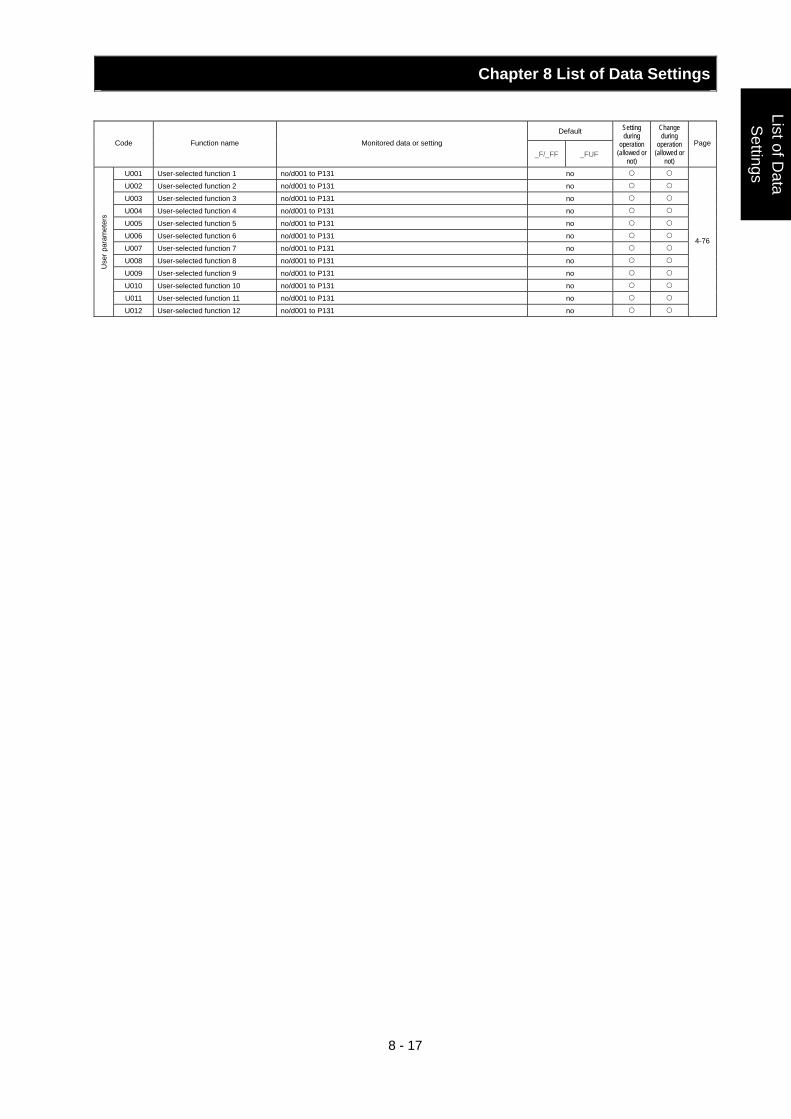
Chapter 8 List of Data Settings
8 - 17
List of Data
Settings
Default Code Function name Monitored data or setting
_F/_FF _FUF
Setting during
operation (allowed or
not)
Change during
operation (allowed or
not)
Page
U001 User-selected function 1 no/d001 to P131 no
U002 User-selected function 2 no/d001 to P131 no
U003 User-selected function 3 no/d001 to P131 no
U004 User-selected function 4 no/d001 to P131 no
U005 User-selected function 5 no/d001 to P131 no
U006 User-selected function 6 no/d001 to P131 no
U007 User-selected function 7 no/d001 to P131 no
U008 User-selected function 8 no/d001 to P131 no
U009 User-selected function 9 no/d001 to P131 no
U010 User-selected function 10 no/d001 to P131 no
U011 User-selected function 11 no/d001 to P131 no
Use
r par
amet
ers
U012 User-selected function 12 no/d001 to P131 no
4-76
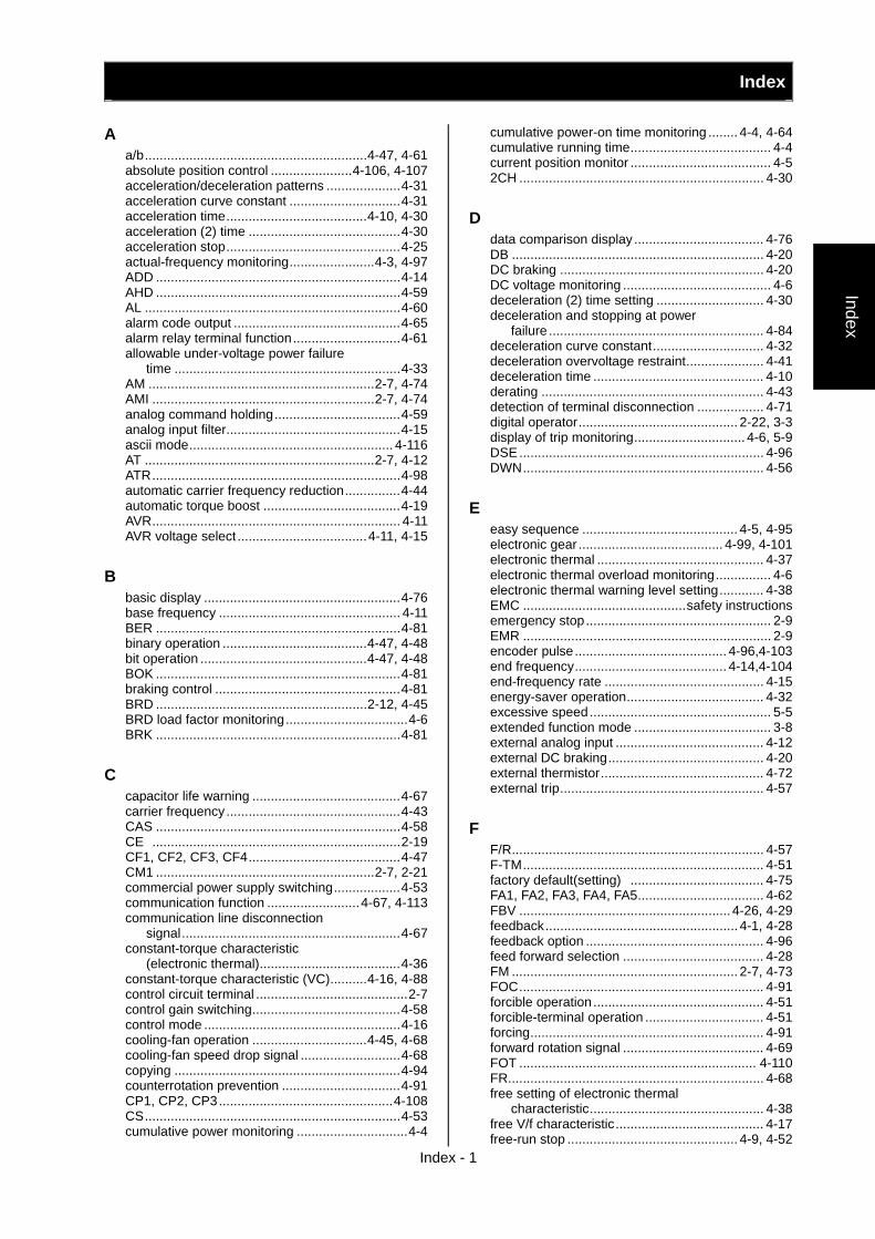
Index
Index - 1
Index
A a/b............................................................4-47, 4-61 absolute position control ......................4-106, 4-107 acceleration/deceleration patterns ....................4-31 acceleration curve constant ..............................4-31 acceleration time......................................4-10, 4-30 acceleration (2) time .........................................4-30 acceleration stop...............................................4-25 actual-frequency monitoring.......................4-3, 4-97 ADD ..................................................................4-14 AHD ..................................................................4-59 AL .....................................................................4-60 alarm code output .............................................4-65 alarm relay terminal function.............................4-61 allowable under-voltage power failure
time .............................................................4-33 AM .............................................................2-7, 4-74 AMI ............................................................2-7, 4-74 analog command holding..................................4-59 analog input filter...............................................4-15 ascii mode....................................................... 4-116 AT ..............................................................2-7, 4-12 ATR...................................................................4-98 automatic carrier frequency reduction...............4-44 automatic torque boost .....................................4-19 AVR................................................................... 4-11 AVR voltage select ...................................4-11, 4-15
B
basic display .....................................................4-76 base frequency ................................................. 4-11 BER ..................................................................4-81 binary operation .......................................4-47, 4-48 bit operation .............................................4-47, 4-48 BOK ..................................................................4-81 braking control ..................................................4-81 BRD .........................................................2-12, 4-45 BRD load factor monitoring.................................4-6 BRK ..................................................................4-81
C
capacitor life warning ........................................4-67 carrier frequency...............................................4-43 CAS ..................................................................4-58 CE ...................................................................2-19 CF1, CF2, CF3, CF4.........................................4-47 CM1 ...........................................................2-7, 2-21 commercial power supply switching..................4-53 communication function .........................4-67, 4-113 communication line disconnection
signal...........................................................4-67 constant-torque characteristic
(electronic thermal)......................................4-36 constant-torque characteristic (VC)..........4-16, 4-88 control circuit terminal .........................................2-7 control gain switching........................................4-58 control mode .....................................................4-16 cooling-fan operation ...............................4-45, 4-68 cooling-fan speed drop signal ...........................4-68 copying .............................................................4-94 counterrotation prevention ................................4-91 CP1, CP2, CP3...............................................4-108 CS.....................................................................4-53 cumulative power monitoring ..............................4-4
cumulative power-on time monitoring ........ 4-4, 4-64 cumulative running time...................................... 4-4 current position monitor ...................................... 4-5 2CH .................................................................. 4-30
D
data comparison display ................................... 4-76 DB .................................................................... 4-20 DC braking ....................................................... 4-20 DC voltage monitoring ........................................ 4-6 deceleration (2) time setting ............................. 4-30 deceleration and stopping at power
failure .......................................................... 4-84 deceleration curve constant.............................. 4-32 deceleration overvoltage restraint..................... 4-41 deceleration time .............................................. 4-10 derating ............................................................ 4-43 detection of terminal disconnection .................. 4-71 digital operator........................................... 2-22, 3-3 display of trip monitoring.............................. 4-6, 5-9 DSE.................................................................. 4-96 DWN................................................................. 4-56
E
easy sequence .......................................... 4-5, 4-95 electronic gear ....................................... 4-99, 4-101 electronic thermal ............................................. 4-37 electronic thermal overload monitoring............... 4-6 electronic thermal warning level setting............ 4-38 EMC ............................................safety instructions emergency stop.................................................. 2-9 EMR ................................................................... 2-9 encoder pulse......................................... 4-96,4-103 end frequency......................................... 4-14,4-104 end-frequency rate ........................................... 4-15 energy-saver operation..................................... 4-32 excessive speed................................................. 5-5 extended function mode ..................................... 3-8 external analog input ........................................ 4-12 external DC braking.......................................... 4-20 external thermistor............................................ 4-72 external trip....................................................... 4-57
F
F/R.................................................................... 4-57 F-TM................................................................. 4-51 factory default(setting) .................................... 4-75 FA1, FA2, FA3, FA4, FA5.................................. 4-62 FBV ......................................................... 4-26, 4-29 feedback.................................................... 4-1, 4-28 feedback option ................................................ 4-96 feed forward selection ...................................... 4-28 FM ............................................................. 2-7, 4-73 FOC.................................................................. 4-91 forcible operation .............................................. 4-51 forcible-terminal operation ................................ 4-51 forcing............................................................... 4-91 forward rotation signal ...................................... 4-69 FOT ................................................................ 4-110 FR..................................................................... 4-68 free setting of electronic thermal
characteristic............................................... 4-38 free V/f characteristic........................................ 4-17 free-run stop .............................................. 4-9, 4-52
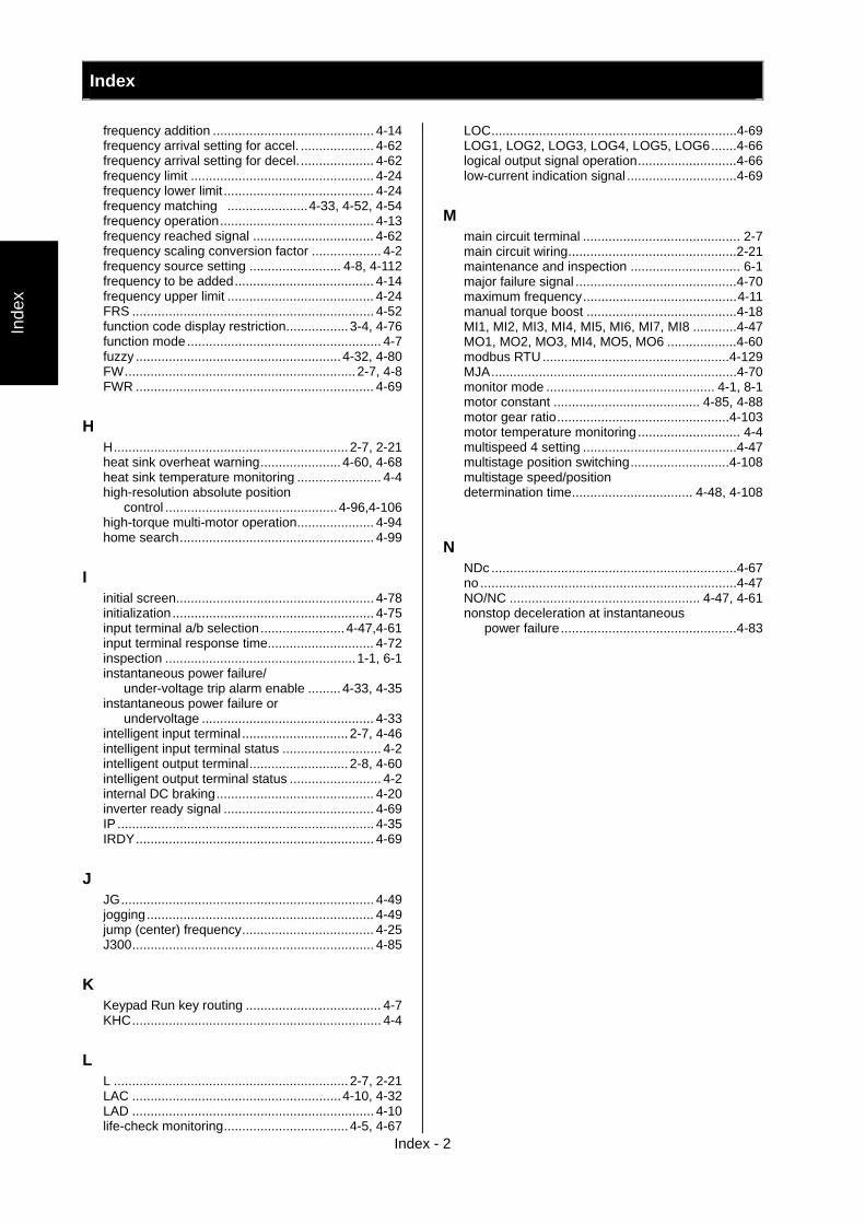
Index
Index - 2
Inde
x
frequency addition ............................................ 4-14 frequency arrival setting for accel. .................... 4-62 frequency arrival setting for decel..................... 4-62 frequency limit .................................................. 4-24 frequency lower limit......................................... 4-24 frequency matching ......................4-33, 4-52, 4-54 frequency operation.......................................... 4-13 frequency reached signal ................................. 4-62 frequency scaling conversion factor ................... 4-2 frequency source setting ......................... 4-8, 4-112 frequency to be added...................................... 4-14 frequency upper limit ........................................ 4-24 FRS .................................................................. 4-52 function code display restriction.................3-4, 4-76 function mode..................................................... 4-7 fuzzy ........................................................ 4-32, 4-80 FW...............................................................2-7, 4-8 FWR ................................................................. 4-69
H
H................................................................ 2-7, 2-21 heat sink overheat warning...................... 4-60, 4-68 heat sink temperature monitoring ....................... 4-4 high-resolution absolute position
control ...............................................4-96,4-106 high-torque multi-motor operation..................... 4-94 home search..................................................... 4-99
I
initial screen...................................................... 4-78 initialization ....................................................... 4-75 input terminal a/b selection.......................4-47,4-61 input terminal response time............................. 4-72 inspection ....................................................1-1, 6-1 instantaneous power failure/
under-voltage trip alarm enable ......... 4-33, 4-35 instantaneous power failure or
undervoltage ............................................... 4-33 intelligent input terminal ............................. 2-7, 4-46 intelligent input terminal status ........................... 4-2 intelligent output terminal........................... 2-8, 4-60 intelligent output terminal status ......................... 4-2 internal DC braking........................................... 4-20 inverter ready signal ......................................... 4-69 IP ...................................................................... 4-35 IRDY................................................................. 4-69
J
JG..................................................................... 4-49 jogging.............................................................. 4-49 jump (center) frequency.................................... 4-25 J300.................................................................. 4-85
K
Keypad Run key routing ..................................... 4-7 KHC.................................................................... 4-4
L
L ................................................................ 2-7, 2-21 LAC .........................................................4-10, 4-32 LAD .................................................................. 4-10 life-check monitoring.................................. 4-5, 4-67
LOC...................................................................4-69 LOG1, LOG2, LOG3, LOG4, LOG5, LOG6.......4-66 logical output signal operation...........................4-66 low-current indication signal ..............................4-69
M
main circuit terminal ........................................... 2-7 main circuit wiring..............................................2-21 maintenance and inspection .............................. 6-1 major failure signal ............................................4-70 maximum frequency..........................................4-11 manual torque boost .........................................4-18 MI1, MI2, MI3, MI4, MI5, MI6, MI7, MI8 ............4-47 MO1, MO2, MO3, MI4, MO5, MO6 ...................4-60 modbus RTU...................................................4-129 MJA...................................................................4-70 monitor mode .............................................. 4-1, 8-1 motor constant ........................................ 4-85, 4-88 motor gear ratio...............................................4-103 motor temperature monitoring ............................ 4-4 multispeed 4 setting ..........................................4-47 multistage position switching...........................4-108 multistage speed/position determination time................................. 4-48, 4-108
N
NDc ...................................................................4-67 no ......................................................................4-47 NO/NC .................................................... 4-47, 4-61 nonstop deceleration at instantaneous
power failure................................................4-83
Index
Index - 3
Index
O O................................................................2-7, 2-21 O2.................................................... 2-7, 2-21, 4-12 O2Dc.................................................................4-71 OD ...........................................................4-28, 4-29 Odc ...................................................................4-71 offline auto-tuning .............................................4-85 OHF ..................................................................4-68 OI ...............................................................2-7, 2-21 OIDc..................................................................4-71 OL, OL2 ............................................................4-40 OLR ..................................................................4-39 online auto-tuning .............................................4-87 ONT ..................................................................4-64 OPE ................................................... 3-3, 4-8, 4-51 operating methods ..............................................3-1 operation after option error ...............................4-79 operation frequency ..........................................4-13 operation mode.................................................4-33 operation time over signal
(RNT)/plug-in time over signal (ONT) .................................................4-59, 4-64
operator ...................................................4-13, 4-66 ORG................................................................4-109 ORL ................................................................4-109 ORT .....................................................4-104, 4-110 OTQ..................................................................4-65 output current monitoring ....................................4-1 output frequency monitoring ...............................4-1 output frequency setting......................................4-7 output signal delay/hold ....................................4-72 output voltage monitoring....................................4-3 overcurrent restraint..........................................4-41 overload notice advance signal................4-39, 4-40 overload restriction............................................4-39 overtorque.........................................................4-65
P
P/PI switching ...................................................4-58 P24 ............................................................2-7, 2-21 PCC ..................................................................4-59 PCLR ................................................................4-96 PCNT .........................................................4-5, 4-59 phase loss input .............................................. 4-36 phase loss input protection ............................. 4-36 PID....................................................................4-26 PIDC .................................................................4-29 POK ................................................................4-104 positioning completed .....................................4-104 position bias....................................................4-103 position command monitor ..................................4-5 position range specification............................. 4-110 power monitoring ................................................4-3 PPI ....................................................................4-58 process variable (PV), PID feedback
monitoring ............................................4-1, 4-29 program counter..................................................4-5 program number monitoring................................4-5 programming error monitoring ............................4-6 programmable controller ...................................2-22 protective function...............................................5-1 pulse counter .............................................4-5, 4-59 pulse train frequency input.............................. 4-112 pulse train position command ...........................4-99
R reduced-torque characteristic
(electronic thermal) ..................................... 4-37 reduced torque characteristic (VP) ................... 4-16 reduced voltage start ........................................ 4-42 remote operation .............................................. 4-56 reset ............................................2-9, 3-3, 4-9, 4-54 restart with input frequency...................... 4-33, 4-36 retry after trip .................................................... 4-33 retry selection ................................................... 4-33 reverse rotation signal .............................. 4-60,4-70 reversible................................................. 4-13, 4-28 RNT .................................................................. 4-64 ROT................................................................ 4-110 rotation direction minitoring................................. 4-1 rotational direction restriction.............................. 4-7 RS ............................................................. 2-9, 4-54 RUN....................................................3-3, 4-4, 4-60 running time over / power-on time over ... 4-60, 4-64 run command source setting .............................. 4-8 running signal ................................................... 4-62 RV .................................................................... 4-46 RVR......................................................... 4-60, 4-70
S
scaled output frequency monitoring.................... 4-2 2nd/3rd control ................................................. 4-50 secondary resistance compensation ................ 4-87 sensorless vector control......................... 4-16, 4-89 servo-on ..........................................................4-111 SET, SET3........................................................ 4-50 SFT................................................................... 4-51 SF1, SF2, SF3, SF4, SF5, SF6, SF7................ 4-47 sign of the frequency to be added .................... 4-14 sink logic........................................................... 2-19 slide switch SW1 ................................................ 2-9 SLV................................................................... 4-16 software lock..................................................... 4-51 SON.................................................................4-111 source logic ...................................................... 2-22 SPD................................................................ 4-108 speed deviation maximum................................ 4-96 speed biasing ................................................. 4-103 speed/position switching................................. 4-108 STA................................................................... 4-57 stabilization constant ........................................ 4-79 start/end frequency setting for external
analog input ................................................ 4-14 start frequency.................................................. 4-14 start-frequency rate .......................................... 4-14 starting contact signal ....................................... 4-68 start with matching frequency.................. 4-33, 4-52 STAT................................................................. 4-96 stop operation selection...................................... 4-9 STOP/RESET key selection ............................... 4-9 STP .................................................................. 4-57 synchronous operation ................................... 4-102
Index
Index - 4
Inde
x
T teaching.......................................................... 4-106 test run ............................................................. 3-10 thermistor ....................................2-8,4-4, 4-72,4-87 THM.................................................................. 4-39 3-wire input ....................................................... 4-57 TL ..................................................................... 4-92 torque bias monitoring ........................................ 4-3 torque biasing ................................................... 4-98 torque boost............................................. 4-17, 4-18 torque command monitoring............................... 4-3 torque control.................................................... 4-98 torque limitation ....................................... 4-92, 4-94 torque LAD stop................................................ 4-94 torque monitoring................................................ 4-3 trip Counter......................................................... 4-5 trip monitoring..................................................... 4-6 troubleshooting ................................................... 5-1 TRQ.................................................................. 4-92 TRQ1, TRQ2 .................................................... 4-92 2-stage acceleration/deceleration..................... 4-30 2CH .................................................................. 4-30
U
UDC.................................................................. 4-56 UL..................................................................... 2-19 unattended start protection ............................... 4-55 UP .................................................................... 4-56 UP/DWN........................................................... 4-56 user monitor........................................................ 4-5 user parameter ......................................... 4-76,4-79 user setting ....................................................... 4-77 USP .................................................................. 4-56 UV ........................................................... 4-35, 4-59
V
V/f gain setting.................................................. 4-15 V2 ...................................................4-16, 4-96, 4-97 VC ................................................................... 4-16 VP 1.7th power ................................................ 4-16 vector control with sensor ........................ 4-17, 4-96
W
WAC ................................................................. 4-67 WAF.................................................................. 4-68 warning function ............................................... 5-10 WCO................................................................. 4-71 WCOI................................................................ 4-71 WCO2............................................................... 4-71 window comparator .......................................... 4-71 wiring of control circuit terminal ........................ 2-21
Z
0Hz detection signal ......................................... 4-64 0Hz-range sensorless vector control ....... 4-16, 4-97 0Hz speed detection signal .............................. 4-64 zero-return function ........................................ 4-109 ZS..................................................................... 4-64
Related Documents