Welcome message from author
This document is posted to help you gain knowledge. Please leave a comment to let me know what you think about it! Share it to your friends and learn new things together.
Transcript


JORDAN-HARE STADIUM SOUTH END ZONE SCOREBOARD REPLACEMENTAU PROJECT NO. 14-286
ELECTRICAL IDENTIFICATION 16175 - 1
SECTION 16175 - ELECTRICAL IDENTIFICATION
PART 1 - GENERAL
1.1 SUMMARY
A. Provide all equipment, materials, tools and labor to properly identify electricalequipment and related accessories.
B. Provide identification for the following:1. Switchgear, switchboards, distribution panels, panelboards, disconnect
switches, circuit breakers, motor starters, motor control switches,start/stop buttons, EPO switches, and other electrical equipment.
2. Junction boxes and pullboxes.3. Wiring devices.4. Wiretags for wiring.5. Raceways.
C. Related Section1. 16200 – Service and Distribution.2. 16140 – Devices.3. 16430 – Motor Controls and Wiring.
PART 2 - PRODUCTS
2.1 IDENTIFICATION
A. Nameplates1. Nameplates shall have the surface color and core color for engraved
letters as follows:a. Normal distribution
1) 277/480V. equipment – white surface with black core2) 120/208V. equipment – black surface with white core
b. Emergency distribution1) 277/480V. equipment – white surface with yellow core2) 120/208V. equipment – yellow surface with white core
2. Provide a nameplate for each switchgear, switchboard, panelboard,distribution panel, motor starter, disconnect switches, motor controlcenter and similar distribution equipment clearly identifying theequipments’ name to match that indicated in the Drawings.
3. Provide a nameplate for each feeder protective device in eachswitchgear, switchboard, distribution panel, motor control centerand any other similar equipment. Identify the specific load it serves
4. Nameplates shall be bakelite, 1/16” thick minimum with 3/8” highletters.
B. Junction Boxes and Pullboxes1. Provide identification with permanent ink marking pen on the cover of
junction boxes noting the branch circuits and systems within the conduit.
JORDAN-HARE STADIUM SOUTH END ZONE SCOREBOARD REPLACEMENTAU PROJECT NO. 14-286
ELECTRICAL IDENTIFICATION 16175 - 2
2. Pullboxes shall be marked using stenciled paint noting the voltage andsystems served. Letters shall be appropriate height so that they can beread from the floor.
3. Boxes containing Emergency systems: write the abbreviation “EMER”above the circuit number on junction box covers. Write“EMERGENCY” in stenciled “RED” paint on pullboxes above othermarkings.
C. Disconnect switches and motor starters1. Provide nameplates as described above for all disconnect switches and
motor starters located 8’-0” above finished floor or less. Identifyequipment served.
2. Provide identification with permanent ink marking pen on all disconnectswitches and motor starters mounted over 8’-0” above finished floor.Write marking clearly and in a location that can be read from the floorwhen the area is finished (e.g. marking for disconnects servingmechanical equipment that will be above the ceiling when the area isfinished shall be located on the bottom or bottom front of the disconnectso it can be read when a ceiling tile is removed).
D. Wiring device wall plates1. For critical care outlets in health care facilities provide identification on
the face of the coverplate with red printed lettering on a white adhesivebackground as to the panel and circuit the outlet is served. Charactersshall be ¼” high.
E. Push button switches1. Provide nameplates as described above for all push button switches.
Letters shall be ¼” high.
F. Emergency power off buttons (EPO)1. Provide nameplates as described above for EPO switches. Nameplate
shall have a red surface and a white core. The letter shall be ½” highreading “EMERGENCY POWER OFF”.
G. Wire markers1. Wire markers for identification of wiring shall be self-adhesive type
having letters and numerals indicating feeder or branch circuit number.Locate markings on wiring where visible near the terminations and tapsin all junction boxes, outlet boxes, panelboards, distribution panelboards, switchboards and motor control centers.
H. Electrical services1. Where multiple electrical services are provided to a building, provide
nameplates as described above identifying the appropriate servicenumber. Letters shall be 1” high.
2. Where the multiple electrical services are in different locations, provide anameplate at each service noting the locations of the other service(s) asrequired by the NEC and the AHJ.
I. Electrical boxes and covers shall be color coded as follows:
JORDAN-HARE STADIUM SOUTH END ZONE SCOREBOARD REPLACEMENTAU PROJECT NO. 14-286
ELECTRICAL IDENTIFICATION 16175 - 3
1. Normal Power – Silver (Unpainted)2. Emergency Power (NEC Art. 700) – Yellow3. Standby Power (NEC Art 701/702) – Orange4. Fire Alarm System – Red – Conduit shall be painted red every 10’ o.c.
(at couplings), at elbows and all back boxes5. Telecommunications – White6. Security - Blue
PART 3 - EXECUTION
A. Nameplates shall be applied to a cleaned surface and shall be plumb and level.
END OF SECTION 16175
JORDAN-HARE STADIUM SOUTH END ZONE SCOREBOARD REPLACEMENTAU PROJECT NO. 14-286
SERVICE AND DISTRIBUTION – 600 VOLT 16200 - 1
SECTION 16200 - SERVICE AND DISTRIBUTION – 600 VOLT
PART 1 - GENERAL
1.1 SUMMARY
A. Provide all distribution switchgear as specified herein, as indicated on the Drawings andas required to provide a complete and operating system. All distribution equipment shallbe of the same manufacturer including, but not limited to, switchboards, panelboards,transformers, disconnects, and busway.
B. The distribution equipment shall be designed, manufactured and tested in accordancewith the latest version of the following standards:1. NFPA 702. NEMA AB13. NEMA KS14. NEMA PB25. NEMA PB16. NEMA PB1.17. NEMA PB2.18. NEMA PB1.19. NEMA 25010. NEMA TP-1-200211. ANSI/IEEE C12.112. ANSI C39.113. ANSI C57.1314. UL 50, 67, 89, 98, 48915. ASTM
C. Provide nameplates for all distribution equipment as specified herein and per Section16175.
D. Refer to Section 16250 for specifications for intelligent panel boards.
1.2 SUBMITTALS
A. The following data shall be submitted according to Division 1 and Section 16010 andshall include but not be limited to:1. Physical dimensions, nameplate data, voltage, amperage, plan views, elevations,
schematic wiring diagrams, bus capacities, circuit schedule, short circuit ratings,etc.
2. The switchgear manufacturer shall provide a coordination study with settings ofall over current protective devices. Over current protective devices shall be fullyrated.
3. The switchgear manufacturer shall provide an ARC Flash study. Provide labelson all switchboards, panels, and other electrical equipment as required per NEC110.16.
JORDAN-HARE STADIUM SOUTH END ZONE SCOREBOARD REPLACEMENTAU PROJECT NO. 14-286
SERVICE AND DISTRIBUTION – 600 VOLT 16200 - 2
B. A ¼” scale dimensioned floor plan shall be provided with the switchgear submittals forall equipment rooms identifying actual size, clearance, access and spacing of theelectrical equipment.
1.3 DELIVERY, STORAGE AND HANDLING
A. Deliver, store, protect, and handle products in conformance with manufacturer’srecommended practices as outlined in application installation and Maintenance Manuals.
B. Each switchboard section shall be delivered in individual shipping splits for ease ofhandling. They shall be individually wrapped for protection and mounted on shippingskids.
C. Inspect and report concealed damage to carrier within their required time period forrepair or replacement.
D. Store in a clean, dry space. Maintain factory protection and/or provide an additionalheavy canvas or heavy plastic cover to protect structure from dirt, water, constructiondebris, and traffic. Where applicable, provide adequate heating within enclosures toprevent condensation.
E. Handle in accordance with NEMA PB 2.1 and manufacturer’s written instructions. Liftonly by lifting means provided for this express purpose. Handle carefully to avoiddamage to switchboard internal components, enclosures, and finish.
1.4 ELECTRICAL SERVICE
A. Provide and install the building electrical service from the utility transformer(s) to themain service distribution equipment..
B. Coordinate all installation requirements with the university prior to bid and include alltrenching, conduits, vaults, equipment pads, current transformers, potential transformers,potential taps as required. Coordinate all Work with the university.
C. Provide conduit, C.T. enclosures, switchgear metering compartments, etc. as required bythe Power Company for metering. Contractor shall coordinate all meter requirementswith the university prior to proceeding with this Work.
D. The secondary service shall be 120/208 volts, 3 phase, 4 wire, 60 Hertz AC.
E. Provide (1) 1” conduit from each power company transformer to the telephone room andmain service distribution equipment for pulse metering interface if available.
PART 2 - PRODUCTS
2.1 SWITCHBOARD – AND ENCLOSED MAIN BREAKER
A. System Description1. Switchboards shall have a minimum short circuit rating of 65,000 amps RMS
unless noted otherwise on the Drawings.
JORDAN-HARE STADIUM SOUTH END ZONE SCOREBOARD REPLACEMENTAU PROJECT NO. 14-286
SERVICE AND DISTRIBUTION – 600 VOLT 16200 - 3
2. Switchboard(s) shall have front access and rear alignment for mounting against awall unless shown otherwise on the Drawings.
B. Standard Features1. Switchboards shall be fully self-supporting structures with 90 inch tall vertical
sections (excluding lifting eyes and pull boxes) bolted together to form requiredarrangement. All sections shall be 36 inches deep unless shown otherwise on theDrawings. Switchboard depth shall be coordinated with room layout andadjusted accordingly to maintain required working clearances.
2. Switchboard(s) shall be NEMA 3R with hinged and latched doors.3. Switchboard frame shall be die formed, 12 gauge steel with reinforced corner
gussets. Frame shall be rigidly bolted to support cover plated (code gauge steel),bus bars and installed devices during shipment and installation.
4. All sections may be rolled, moved or lifted into position. Switchboards shall becapable of being bolted directly to the floor without the use of floor sills.
5. All switchboard sections shall have open bottoms and removable top plates(s) toinstall conduit.
6. Front-Access only switchboard sections shall be rear aligned for placementagainst a wall. Provide front and rear accessible switchboards where both frontand rear access is shown to be available on the Drawings.
7. Switchboards shall be UL listed to accept a combination of circuit breakersand/or fused switches, where applicable, factory or field installed.
8. Switchboards that are series rated to short circuit requirements shall beappropriately labeled. Tested UL listed combination ratings shall be included inUL recognized Component Directory (DKSY2).
9. All covers shall be fastened by hex head bolts.10. Provide hinged doors over metering compartments and individually mounted
device compartments. All doors shall have concealed hinges and be fastened byhex head bolts.
11. Switchboards protective devices shall be provided as listed on Drawings andspecified herein, including interconnections, instrumentation and control wiring.Switchboards and devices shall be rated for the voltage and frequency as shownon the Drawings.
12. Switchboard current ratings, including all devices, shall be based on a maximumambient temperature of 25 degree C per UL Standard 891. With no deratingrequired, temperature rise of switchboards and devices shall not exceed 65degrees C in a 25 degree C ambient environment.
13. Switchboard Service Entrance sections shall comply with UL Service Entrancerequirements including UL service entrance label, incoming line isolationbarriers, and a removable neutral bond to switchboard ground for solidlygrounded wire systems.
14. Construction shall allow for the maintenance of all terminations, deviceconnections and bolted bus connections.
15. Provide all spare spaces and circuit protective devices as indicated on theDrawings. All unused spaces provided, unless otherwise specified, shall be fullyequipped for future devices, including all appropriate connectors and mountinghardware.
16. Provide all necessary wiring, fuse blocks and terminal blocks within theswitchboard as required. All groups of control wires shall be provided withterminal blocks with numbering strips.
JORDAN-HARE STADIUM SOUTH END ZONE SCOREBOARD REPLACEMENTAU PROJECT NO. 14-286
SERVICE AND DISTRIBUTION – 600 VOLT 16200 - 4
17. Provide nameplates for each switchboard and each overcurrent device inaccordance with Section 16175 “Electrical Identification”.
18. Switchboard enclosures and structure shall be painted on all sides afterfabrication with enamel over a rust-inhibiting primer coat or protected by anelectro-deposition or powder coat paint process.
C. Bus Bars1. Bus bars shall be silver-plated copper. Plating shall be applied continuously to
all bus work. The bus bars shall have sufficient cross sectional area to meet UL891 temperature rise requirements through actual tests. The bus bars shall bestandard density rated for 1000 amperes per square inch. Phase and neutral busampacity shall be as shown on the plans. The neutral bus shall have the sameampacity as the phase bus.
2. Bus bars shall be mounted on high impact, non tracking insulated supports.Joints in the vertical bus are not permitted.
3. Bus bars shall be braced to withstand mechanical forces exerted during shortcircuit conditions as indicated in Drawings, but in no case less than 65KA RMSSYM.
4. Bus joints shall be bolted with high tensile steel bolts. Belleville type washersshall be provided with aluminum bus. Welded connections are unacceptable.
5. Main horizontal bus bars shall be fully rated and arranged for future extensions.Full provisions shall be provided for the addition of future sections. Bussingshall include all necessary hardware to accommodate splicing for futureadditions.
6. A-B-C bus arrangement (left to right, top to bottom, front to rear) shall be usedthroughout to assure convenient and safe testing and maintenance. Where specialcircuitry precludes this arrangement, bus bars shall be labeled.
7. All feeder device line and load connections traps shall be rated to carry currentrating of device frame (not trip rating).
8. The main incoming bus bars shall be rated for the main protection device framesize or main incoming conductors, if there is no main device.
9. Ground bus shall be sized to meet UL 891. Ground bus shall extend full lengthof switchboard. Provisions for the addition of future connections and futuresections shall be provided as previously indicated.
10. The horizontal and vertical main bus bars shall remain full size throughout theirfull length. Bus reductions other than those indicated on the Drawings are notacceptable.
11. Where “space” is provided or indicated on the Drawings, the space shall bebussed.
D. Main Incoming Compartment1. Provide switchboard(s) arranged for bottom entry of incoming cable or top entry
of incoming cable, whichever is indicated on Drawings.a. All lugs shall be tin-plated aluminum and UL listed for use with copper
cable. Lugs shall be rated for 75 degree C cable.b. Provide double crimp compression type lugs in the quantity and size
required.
E. Main and Feeder Devices1. Main device shall be individually mounted insulated case circuit breaker Provide
device as shown on the Drawings and as specified in appropriate article below.
JORDAN-HARE STADIUM SOUTH END ZONE SCOREBOARD REPLACEMENTAU PROJECT NO. 14-286
SERVICE AND DISTRIBUTION – 600 VOLT 16200 - 5
2. Feeder devices shall be group mount molded case circuit breakers or when largerthan 1200 amps shall be individually mounted insulted case circuit breakers.Provide devices as specified in appropriate article below.
3. All circuit protective devices minimum symmetrical current interrupting capacityshall be as shown on the Drawings, but on no case less than 65KA RMS SYM.
4. All main breakers and feeder breakers 1200A or larger shall be connected to aenergy reducing maintenance switch with indicator light. Device shall complywith NEC Article 240.87.
F. Molded Case Circuit Breakers1. Thermal magnetic molded case circuit breakers may be provided for trip ratings
160 amps and below.2. Group mounted breakers shall be modular mounted. The module shall be
electrically connected to the switchboard bus by spring reinforced jaws.Mechanical connections to panel frame shall be separate from electricalconnections. Mechanical connections shall be self-aligning, spring loadedlocking devices. Locking device handles shall be able to be bolted to each sideof the device to prevent accidental release of electrical connections.
3. Individually mounted molded case circuit breakers shall be stationary mounted.4. Circuit breaker frames shall be constructed of a high-strength, molded, glass-
reinforced polyester case and cover. Breakers shall have an overcenter, togglehandle-operated, trip free mechanism with quick make, quick break actionindependent of the speed of the toggle handle operation. The design shallprovide common tripping of all poles. Breakers shall be suitable for reversefeeding.
5. Breakers shall have ON and OFF positions clearly marked on escutcheon.Breakers shall include a trip-to-test means on the escutcheon for manuallytripping the breaker and exercising the mechanism and trip latch.
6. Breakers shall include factory installed mechanical lugs. Lugs shall be UL listedand rated 75 degrees C. .
7. Breakers larger than 225 amps shall use digital true RMS sensing trip units and arating plug to determine the breaker trip rating.
8. Each feeder breaker with a frame size 400 amps and larger shall have a digitalelectronic trip unit as described in section “Digital Electronic Trip Unit forCircuit Breakers” with in this document.
G. Insulated Case Circuit Breakers1. Insulated case circuit breakers shall be individually mounted.2. Main breakers shall be manually operated, stationary mounted. Feeder breakers
(larger than 1200 amps) shall be manually operated, stationary mounted.3. Breakers shall be constructed of a high dielectric strength, glass reinforced
insulating case. The interrupting mechanism shall be arc chutes. Steel vent gridsshall be used to suppress arcs and cool vented gases. Interphase barriers shall beused to completely isolate each pole.
4. Breakers shall contain a true two-step stored energy operating mechanism whichshall provide quick make, quick break operation with a maximum five cycleclosing time. Breakers shall be trip free at all times. Common tripping of allpoles shall be standard.
5. Insulated Case circuit breakers shall be rated to carry 100 percent of their frameampacity continuously.
JORDAN-HARE STADIUM SOUTH END ZONE SCOREBOARD REPLACEMENTAU PROJECT NO. 14-286
SERVICE AND DISTRIBUTION – 600 VOLT 16200 - 6
6. A charging handle, close push-button, open push-button, and OFF/ON/Chargeindicator shall be located on the breaker escutcheon and shall be visible with thebreaker compartment door closed.
7. Each main breaker shall have a digital electronic trip unit as described below.
H. Digital Electronic Trip Unit for Circuit Breakers1. Provide digital electronic trip units as specified below.2. Each main and feeder circuit breaker 400A and above shall be equipped with a
digital electronic trip unit. The trip unit shall provide protection from overload,short circuits and ground faults. The protective trip unit shall consist of a solidstate, microprocessor based programmer, tripping means, current sensors, powersupply and other devices as required for proper operation.
3. As a minimum, the trip unit shall have the following protective functions:a. Adjustable current setting or long time pickup;b. Adjustable long time delay;c. Adjustable instantaneous pickup;d. Adjustable ground fault pickup and delay for main and designated
feeders;e. Adjustable short time pickup and delay for main and designated feeders.
4. As a minimum, the trip unit shall include the following features:a. Long time and short time protective functions, if provided, shall have
true RMS sensing technology.b. Ground fault protective function, if provided, shall contain a memory
circuit to integrate low level arcing fault currents with time, to sum theintermittent ground fault spikes.
c. High contrast liquid crystal display (LCD) unit shall display settings, triptargets, and the specified metering displays.
d. Multi-button keypad to provide local setup and readout of all trip settingson the LCD.
e. UL listed interchangeable rating plug. It shall not be necessary toremove the trip unit to change the rating plug.
f. An integral test jack for testing via a portable test set and connection to abattery source.
g. A mechanism for sealing the rating plug and the trip unit.h. Noise immunity shall meet the requirement of IEEE C37.90.i. Display trip targets for long time, short time, and ground fault, if
included.5. The main breakers’ trip unit shall include the following metering functions,
which shall be displayed on the LCD (if the manufactures trip unit cannotincorporate the specified functions, separate device(s) with equal function shallbe provided for each breaker):a. Current, RMS, each phase;b. Voltage, RMS, line-to-line, or line-to-neutral;c. Energy, KWH, total;d. Demand KWH, over an adjustable time period of 5 to 60 minutes;e. Peak demand, KW, user resettable;f. Real power, KW, line-to-line, line-to-neutral;g. Total (apparent) power, KVA, line-to-line, line-to-line neutral.
6. The feeder breakers’ trip unit shall include the following metering functionwhich shall be displayed on the LCD:a. Current, RMS, each phase.
JORDAN-HARE STADIUM SOUTH END ZONE SCOREBOARD REPLACEMENTAU PROJECT NO. 14-286
SERVICE AND DISTRIBUTION – 600 VOLT 16200 - 7
7. All main breaker trip units shall have communication capability.
I. Metering Transformers1. All instrument transformers shall be UL listed and classified as indicated in
Drawings.2. Current Transformers shall be provided with burden and accuracy to support
connected meters and relays as required by [ANSI/IEEE C57.13].3. Potential transformers shall be provided with burden and accuracy to support
connected meters and relays as required by [ANSI/IEEE C57.13].
J. Accessories1. Provide Taylor Electronics Model #PND-3, 6, 9, 12 ADJ-REM LED’s or equal,
single phase relay behind hinged panel in switchboard. Provide green and amberLED’s on a plug in cable for mounting on face of switchboard. Provide snap onlenses and labels identifying the green LED as “SYSTEM NORMAL” and theamber LED as “SINGLE PHASE CONDITION”.
2. Provide shunt trip coils on all main devices, operated by the phase failure relay.3. Provide capacitive trip unit to guarantee relay and shunt trip operation during a
single phase occurrence.
K. Main switchboard shall be as manufactured by General Electric, Square D, Cutler-Hammer and Siemens.
2.2 PANELBOARDS
A. System Description1. Short circuit rating of panelboards shall be the interrupting rating of lowest rated
device in the panel or application UL series for proper main and branch devicecombinations.
2. Panelboards shall have a maximum of 42 protective devices per panel, includingsub-feeders and excluding main overcurrent protective devices. For more than42 devices, 2 or more panelboards are required.
3. With 2 or more panelboards, sub-feed lug or thru-feed lugs shall be used in all by1 section of each panelboard. Lugs shall have same capacity as incoming mains.
4. Protective devices shall be molded case circuit breakers.
B. Enclosure1. Boxes shall be a nominal 20 inches wide and 6 inches deep with wire bending
space per the National Electric Code.2. Fronts shall be door-in-door construction with reinforced steel with concealed
hinges and concealed trim adjusting screws. Trim clamps are unacceptable.3. All door locks shall be corrosion proof Valox (or equal) with retractable latches.
All door locks shall be keyed for a single key.4. Clean Lexan (or equal) directory card holders shall be permanently mounted on
front door.5. All panelboard series ratings shall be prominently displayed on dead front shield.6. Interiors shall permit top or bottom incoming cables.
C. Bus bars1. Bus bars shall be copper, phase sequenced, fully insulated and supported by high
impact Noryl (or equal) interior base assemblies.
JORDAN-HARE STADIUM SOUTH END ZONE SCOREBOARD REPLACEMENTAU PROJECT NO. 14-286
SERVICE AND DISTRIBUTION – 600 VOLT 16200 - 8
2. Bus bars shall be mechanically supported by zinc finished galvanneal steelframes to prevent vibration and damage from short circuits.
3. Terminations shall be UL tested and listed and suitable for UL copper.4. Provide 1 continuous bus bar per phase. Each bus bar shall have sequentially
phased branch circuit connectors for bolt-on branch circuit breakers. Bus barsshall be rated as indicated in Drawings.
5. Split solid neutral bus shall be plated and located in main compartment for allincoming neutral cables to be same length. 200% rated solid neutral shall beprovided as indicated on the Drawings and shall be plated copper for non-linearload applications subject to harmonics. 200% rated solid neutral shall be self-certified by Manufacturer.
6. Lugs shall be rated for 75 degree C terminations.7. Interiors shall be field convertible for top or bottom incoming feed. Main and
sub-feed circuit breakers shall be vertically mounted. Main lug interiors up to400 amperes shall be field convertible to main breaker. Interior levelingprovisions shall be provided for flush mounted applications.
8. Log bodies shall bolt in place.
D. Circuit Breakers1. Molded case circuit breakers shall be bolt-in devices for 120/208V panels and
277/480V panels.2. All circuit breakers shall have thermal and magnetic trip elements in each pole.3. Multiple pole breakers shall have internal common trip crossbars for
simultaneous tripping of each pole.4. Circuit breakers shall not be restricted to any mounting location due to physical
size.5. All branch breakers 15 to 100 amperes shall be able to be mounted in any panel
position for twin or double mounting without space penalty. Sum of ratings for 2such twin mounted devices shall not exceed 180 amperes.
6. Main and sub-feed circuit breakers may be vertically or horizontally mounted.7. Branch breaker panelboard connections shall be copper to copper.8. All panelboard terminations shall be rated as indicated in Drawings.9. All breakers shall have an over center mechanism and be quick make and quick
break.10. All breakers shall have handle trip indication and a trip indicator in window of
circuit breaker housing.11. Breaker handle and faceplate shall indicate rated ampacity.12. Circuit breaker escutcheon shall have standard ON/OFF markings.13. Main breakers shall be UL listed for use with: Shunt, Under Voltage, and Ground
Fault Shunt Trips; Auxiliary and Alarm Switches; and Mechanical Lug Kits.14. Branch breakers shall be UL listed for use with: Shunt Trips, Auxiliary and
Alarm Switches.
E. Finish1. Boxes shall be corrosion resistant, zinc finish galvanneal.2. Fronts shall be powder finish painted ANSI 61 gray.
F. Panels shall be manufactured by General Electric, Square D, Cutler-Hammer or Siemens.
2.3 DISTRIBUTION PANELBOARDS
JORDAN-HARE STADIUM SOUTH END ZONE SCOREBOARD REPLACEMENTAU PROJECT NO. 14-286
SERVICE AND DISTRIBUTION – 600 VOLT 16200 - 9
A. System Description1. Equipment shall be indoor deadfront power panelboards for molded-case circuit
breakers.2. Panelboards shall meet service entrance equipment where indicated on the
Drawings.3. Panelboards shall have integrated short circuit rating. Fully rated panel rating is
that of lowest rated device in panelboard. Series ratings are for the UL testedmain-branch combination.
B. Enclosures1. Panel box shall be galvanized code gauge sheet steel with removable end walls.2. Enclosures shall be surface mounted.
C. Fronts1. Provide a four-piece front to cover wiring gutter and wiring access areas.
Provide a lockable hinged door with semi-concealed hinges to cover access tocircuit breakers.
2. Hinged door fronts, when specified, shall be provided with a lockable inner doorwith leaf hinges. An inner door shall cover the circuit protective devices andshall be able to be locked.
3. Door hinges shall be continuous piano hinges, welded to door(s) and bolted onfront.
4. Door locks shall be Yale #511.
D. Interiors1. Panelboard interior shall by symmetrically designed and assembled such that
circuit protective modules are connected onto bus bar with positive gripping jawassemblies and locked pressure connections.
2. Circuit-protective modules shall be designed for removal or replacement withoutdisturbing adjacent protective devices and without removing main bus andbranch circuit connections.
3. Interiors shall allow installation of molded-case circuit breakers in samepanelboard.
4. Lugs shall be UL listed to accept solid or stranded copper cables. Lugs shall bebolted in place.
5. Panelboards shall be rated as indicated in Drawings. Main devices shall havemaximum rating of 1200 amperes.
6. Panelboards shall have flat, stacked, vertically aligned bus bars.7. Bus bars shall be copper. The bus bars shall have sufficient cross sectional area
to meet UL 67 temperature rise requirements through actual tests. The bus barsshall be standard density rated for 1000 amperes per square inch.
8. Bus bars shall be phase-sequenced and rigidly supported by high impact resistant,insulated bus supporting assemblies to prevent vibration or short circuitmechanical damage.
9. Neutral bus shall be fully rated and able to be located in either corner ofenclosure at line end to facilitate conductor termination. Provide 200% ratedneutral bus, if required by plans or another specification section.
10. All solderless terminations shall be suitable for copper UL listed wire or cableand shall be tested and listed in conjunction with appropriate UL standards.Terminations shall be rated for use with conductor ampacity as assigned in theNEC 75 degree C table.
JORDAN-HARE STADIUM SOUTH END ZONE SCOREBOARD REPLACEMENTAU PROJECT NO. 14-286
SERVICE AND DISTRIBUTION – 600 VOLT 16200 - 10
11. Ground wire terminations shall be provided as an optional kit for installation bypanelboard installer without voiding UL label.
E. Main and Branch Devices1. Circuit breakers
a. Main and branch circuit breaker shall be quick-make, quick-break, andtrip indicating, low voltage molded-case.
b. Circuit breaker case shall have ON/OFF and International I/O positionindicators.
c. Breaker faceplate shall list current rating, UL and IEC certificationstandards, and AIC ratings.
d. Circuit breakers shall be factory sealed and shall be date coded onbreaker case.
e. Breakers shall be UL listed for reverse connection without restrictive lineor load markings. Circuit breakers shall be able to mount in anyoperating position.
f. 3-pole breakers with ampere ratings greater than 150 ampere shall haverating plugs.
g. All circuit protective devices shall have the following minimumsymmetrical current interrupting capacity of 18kA. Interrupting rating ofbreakers shall not be less than maximum short circuit current available atincoming line terminals as shown on plans.
h. Breakers shall have UL listed series ratings, if specified in Drawings.i. Main breakers and lugs shall be convertible by installer for top or bottom
incoming feed.j. Where indicated on the drawings, elsewhere in the specifications, or as
required for coordination, the main breaker shall be provided withintegral ground pick-up and delay settings and adjustable long time,instantaneous and short time settings.
F. Series Ratings1. Panelboard series-connected ratings shall be attached to the panelboard
enclosure.
G. Distribution panels shall be manufactured by General Electric, Square D, Cutler-Hammeror Siemens.
2.4 TRANSFORMERS
A. System Description1. Power transformers shall be 2 winding dry type for general power and lighting
applications. Transformers rated 1000 KVA or below shall be UL listed, NEMATP-1-2002 standard for energy efficiency, and bear required UL Listing Mark.
B. Dry-type general purpose transformers shall be rated as indicated in Drawings.
C. Transformers shall use properly classified UL approved temperature ratings.Temperature rise ratings shall be in accordance with UL 506. ??Insulation ratings shallbe as indicated in Drawings.??
JORDAN-HARE STADIUM SOUTH END ZONE SCOREBOARD REPLACEMENTAU PROJECT NO. 14-286
SERVICE AND DISTRIBUTION – 600 VOLT 16200 - 11
D. Transformers shall be UL recognized 200 degree insulation system and shall be designedso that under full load the average conductor temperature rise does not exceed 115degrees C rise above a 40 degree C ambient and the enclosure does not exceed a 50degree C rise at any point.
E. Transformers 5 KVA and above shall be able to meet ANSI/IEEE C57.96 daily overloadrequirement listed in Drawings. Transformers loaded in accordance with this paragraphshall be capable of long service life under thermal conditions specified. There shall be noneed for derating.
F. Transformers shall have sound levels equal to or lower than those established in latestrevision of ANSI/IEEE C89.2 as shown in drawings.
G. Enclosures shall meet UL 506 requirement for the following characteristics:1. Ventilation Openings;2. Corrosion Resistance;3. Cable Bending Space;4. Surface Temperature Rise;5. Wiring Compartment Temperature Rise;6. Terminations;
H. Transformer Construction1. Transformer cores shall be constructed of high grade, non-aging silicon steel with
high magnetic permeability and low hysteresis and eddy current losses.Magnetic flux densities shall be kept well below core saturation point. Corelaminations above 112.5 KVA shall be miter cut at core corners to reduce hotspots, core loss, current and sound level. Core laminations shall be clampedtogether with steel angles. Cores for transformers above 300 KVA shall beclamped using insulated bolts through core laminations to provide properpressure throughout core length. Completed core and coil shall be bolted toenclosure base and isolated from base by rubber vibration-absorbing mounts.There shall be no metal-to-metal contact between core and coil and enclosure.Sound isolation systems requiring complete removal of all fastening devices isnot acceptable.
2. Transformer core shall be visibly grounded to enclosure by flexible groundingconductor meeting UL and NEC size requirements.
3. Enclosure shall be constructed of heavy gauge steel.4. Coils shall be copper.
I. Load Taps1. Transformers shall have following high voltage load tap arrangements unless
noted otherwise in plans:a. Through 2 KVA – no taps;b. Through 23 KVA – no taps;c. 3 though 23 KVA 2 above, 2 below nominal 4, 2-1/2 percent taps
voltage;d. Through 500 KVA – 6, 2-1/2 percent taps, 2 above, 4 below nominal
voltage.
J. Finish
JORDAN-HARE STADIUM SOUTH END ZONE SCOREBOARD REPLACEMENTAU PROJECT NO. 14-286
SERVICE AND DISTRIBUTION – 600 VOLT 16200 - 12
1. Finish shall consist of degreasing, phosphate cleaning, and electrodeposits ANSIgray enamel paint.
H. Transformers – standard shall be as manufactured by General Electric or Square D,Cutler-Hammer or Siemens.
2.5 DISCONNECT SWITCHES
A. Switches shall be heavy-duty type. The switch blades shall be visible when the switch isOFF and the cover is open. Lugs shall be front removable and UL listed for 75 degrees Cconductor. Provide removable arc suppressor to facilitate easy access to line side up.
B. Switches shall have provisions for a field installable electrical interlock.
C. The switch operating mechanism shall be quick-make, quick-break.
D. Provide padlock provisions for locking in the OFF position.
E. Provide NEMA type enclosure suitable for the application (indoor, outdoor, wet or damp,corrosive, etc.). Type 3R enclosure shall contain no knockouts (supply watertight hubs).
F. Enclosure shall have ON and OFF markings stamped on the enclosure.
G. Switches shall be horsepower rated.
H. Fused disconnect switches shall have rejection type fuse clips with dual element currentlimiting fuses of rating shown or required by the Manufacturer’s nameplate of theequipment being supplied. The UL short circuit rating shall be 200,000 amps RMS SYMwhen used with Class R or J fuses.
2.6 FUSES
A. Fuses shall have 200,000 Amp RMS SYS rating.
B. Fuses for circuits 1 to 600 amperes shall be dual element, current limiting time delay(500% of rated current for minimum of 10 seconds) with separate overload and shortcircuit clearing chamber. Bussman “Low Peak” or equal by Littlefuse or FerrazShawmut. UL Class J.
C. Fuses for circuits above 600 amperes shall be current limiting, time delay (500% of ratedcurrent for minimum of 4 seconds, clear 20 times rated current in 0/1 seconds or less).Bussman, “Hi-Cap” or equal by Littlefuse or Ferraz Shawmut. UL Class L.
D. Provide one (1) set of spare fuses for each set of three (3). A maximum of three (3) setsof fuses is required to be provided for the same type and rating.
PART 3 - EXECUTION
1.1 GENERAL

JORDAN-HARE STADIUM SOUTH END ZONE SCOREBOARD REPLACEMENTAU PROJECT NO. 14-286
SERVICE AND DISTRIBUTION – 600 VOLT 16200 - 13
A. Clean all enclosures free of all foreign matter and dust.
B. Remove all rust marks and repaint to new condition.
C. Provide all necessary hardware to level and secure all switchgear.
D. Provide engraved nameplates on all switchgear per Section 26 05 50 including but notlimited to, switchboards, switchboard overcurrent protection devices, panelboards,distributor panelboards, disconnects, contactors, busway, busplugs.
E. Provide a typewritten directory for all panelboards. Make spares in pencil.
1.2 FIELD TESTING
A. Infra-red Testing1. After the electrical distribution system has been checked, adjusted, calibrated and
under load just prior to substantial complete, it shall be subjected to an infra-redthermograph test by a NETA certified technician. The test shall be performedwith a minimum load of 20% of the rating of the equipment/connection beingtested. Load banks shall be supplied if necessary to provide this load factor.
2. Two (2) copies of the test report shall be provided to the Engineer uponcompletion of the test. Connections indicated having higher temperatures thanacceptable shall be tightened or corrected as required. After corrections havebeen made, the connections shall be subjected to an additional thermograph testand rechecked to confirm the problem has been corrected.
3. The following components and connections shall be included in the thermographtesting:a. Service entranceb. Switchboardsc. Switchboard main and feeder devicesd. Feeder tapse. Busway cable terminationsf. Busway jointsg. Bustaps and busplug connectionsh. Emergency distribution systemi. UPS systemj. Motor control centersk. Distribution panelsl. Panelboardsm. Mechanical equipment connections (over 100 amps)n. Transformers
END OF SECTION 16200
JORDAN-HARE STADIUM SOUTH END ZONE SCOREBOARD REPLACEMENT
AU PROJECT NO. 14-286
INTELLIGENT PANELBOARD 16250 - 1
SECTION 16250 - INTELLIGENT PANELBOARD FOR LIGHTING CONTROL AND ENERGYMANAGEMENT
PART 1 GENERAL
1.01 SCOPE
A. The Contractor shall furnish and install Lighting Control Panelboards as specified and as shown on thecontract drawings.
B. The Lighting Control System work shall be indicated on the drawings and by the requirements of thissection. It is defined to include, but not limited to:1. Intelligent panelboards, containing both standard and remotely controlled circuit breakers, control
electronics and metering options2. Intelligent panelboard accessories such as low voltage and digital (network) switches3. Software and system management equipment4. System startup and training5. Interface with Johnson Controls. Coordinate all necessary interface requirements with the local
Johnson Controls technician prior to shop drawing submittals.
1.02 RELATED SECTIONS
A. Section 16200 – Service and Distribution
B. Section 16900 – Energy Management System Lighting Control
1.03 REFERENCES
A. NEMA Compliance: Comply with applicable portions of NEMA standards pertaining to types ofelectrical equipment and enclosures.
B. UL Listing: Lighting Control Panelboards shall be UL listed under UL 916 Energy ManagementEquipment, UL 67 Panelboard Interiors and UL 50 Panelboard Box.
C. NEC compliance: Comply with applicable portions of the NEC including Article 110-10.
D. California Title 24: All control equipment shall be California Title 24 compliant.
E. New York City Authority: All panelboards shall be certified for use in New York City by the NewYork City Authority.
F. FCC Emissions: All control equipment shall be in compliance with FCC emissions standards in Part 15Subpart J for Class A application.
1.04 SUBMITTALS – FOR REVIEW/APPROVAL
A. The following information shall be submitted to the Engineer:1. Breaker layout drawing with dimensions indicated and nameplate designation2. Component list3. Conduit entry/exit locations4. Assembly ratings including:
JORDAN-HARE STADIUM SOUTH END ZONE SCOREBOARD REPLACEMENT
AU PROJECT NO. 14-286
INTELLIGENT PANELBOARD 16250 - 2
a. Short-circuit ratingb. Voltagec. Continuous current
5. Cable terminal sizes6. Product data sheets. Submit manufacturer’s data sheets on system submitted and components
supplied, with complete descriptions of hardware and software components supplied7. Series rating information8. Interface to Electrical Monitoring and Control System9. Interface to Building Automation System/Energy Management System
B. Wiring Diagrams – Submit typical wiring diagrams for all components including, but not limited to,smart panelboard, application specific controllers, override switches, daylighting components, dimmingballasts, telephone lines, network wiring, and the central operator’s station.
1.05 SUBMITTALS – FOR CONSTRUCTION
A. The following information shall be submitted for record purposes:1. Final as-built drawings and information for items listed in Paragraph 1.04, and shall incorporate all
changes made during the manufacturing process2. Panelboard Load Schedule: Show load placement and sizing3. Wiring Diagrams: Show typical interconnect wiring diagram for each system component supplied4. Installation Guide: Provide instructions on how to install system components5. Seismic certification and equipment anchorage details as specified
1.06 QUALIFICATIONS
A. The manufacturer of the assembly shall be the manufacturer of the major components within theassembly. Panelboards specified in this section shall be manufactured by Eaton to match existinglighting control panels within the min concourse level of the stadium. Panel construction shall complywith Section 16200.
B. For the equipment specified herein, the manufacturer shall be ISO 9001 or 9002 certified.
C. The manufacturer of this equipment shall have produced similar electrical equipment for a minimumperiod of five (5) years. When requested by the Engineer, an acceptable list of installations with similarequipment shall be provided demonstrating compliance with this requirement.
D. The manufacturer of the lighting control panelboard shall be regularly engaged in manufacture ofelectrical distribution equipment, lighting control and/or energy management equipment of types andcapacities required and shall be the manufacturer of the remote controllable circuit breakers containedin the system.
1.07 REGULATORY REQUIREMENTS
A. The lighting control panelboard shall be labeled and listed under UL 916 Energy ManagementEquipment, UL 67 Panelboard Interiors and UL 50 Panelboard Box.
B. All control equipment shall be in compliance with FCC emissions' standards in Part 15 Subpart J forClass A application.
1.08 DELIVERY, STORAGE AND HANDLING
JORDAN-HARE STADIUM SOUTH END ZONE SCOREBOARD REPLACEMENT
AU PROJECT NO. 14-286
INTELLIGENT PANELBOARD 16250 - 3
A. Equipment shall be handled and stored in accordance with manufacturer’s instructions. One (1) copy ofthese instructions shall be included with the equipment at time of shipment.
1.09 OPERATION AND MAINTENANCE MANUALS
A. Equipment operation and maintenance manuals shall be provided with each assembly shipped and shallinclude instruction leaflets, instruction bulletins and renewal parts lists where applicable, for thecomplete assembly and each major component.
PART 2 PRODUCTS
2.01 MANUFACTURERS
A. Eaton to match existing main concourse lighting relay panels with Johnson Controls N2 controllers. Noexceptions.
The listing of specific manufacturers above does not imply acceptance of their products that do not meetthe specified ratings, features and functions. Manufacturers listed above are not relieved from meeting thesespecifications in their entirety. Products in compliance with the specification and manufactured by othersnot named will be considered only if pre-approved by the engineer ten (10) days prior to bid date.
2.02 GENERAL
A. Intelligent Panelboard systems shall be comprised of Master Panelboards and optional ExpansionPanelboards. Intelligent Panelboards shall use remotely controllable circuit breakers for automaticpower switching. Intelligent Panelboards shall be integrated and modular; External time clocks, relaycircuits and/or contactor circuits will not be accepted.
B. IntelligentPanelboards shall accept non-controlled and low voltage remotely controlled thermalmagnetic branch circuit breakers. Intelligent Panelboards shall use standard panelboard interiors andenclosures
C. Control functionality shall be an integral part of the panelboard. Master Panelboards shall be capableof multi-zone, automatic power switching with integral time clock function and provisions for manualswitch overrides.
D. The Master Panelboard shall be furnished with a power supply to provide control power to electroniccomponents and remotely controlled circuit breakers. The power supply shall have a local accessibleON/OFF switch and secondary thermal magnetic ON/OFF protection. The power supply shall be fedfrom panelboard bus. The power supply shall be capable of powering a total of 168 circuit breakerslocated in multiple panelboards.
E. Standard Expansion Panelboards shall obtain all control power from the Master Panelboard. Thecontrol power and communication interconnections of Expansion Panelboards shall be listed as a Class2 circuit for compatibility with standard communications cables and products, either at installationtime or to support additions to the system in the future. Systems in which these connections are listedas Class 1 shall provide isolation devices to meet NEC requirements as may be required for theinstallation.
F. Powered Expansion Panelboards shall further include a power supply so that they may be located at anextended distance. The power supply shall provide control power to electronic components and

JORDAN-HARE STADIUM SOUTH END ZONE SCOREBOARD REPLACEMENT
AU PROJECT NO. 14-286
INTELLIGENT PANELBOARD 16250 - 4
remotely controlled circuit breakers. The power supply shall have a secondary thermal magneticON/OFF protection. The power supply shall be fed from panelboard bus. The power supply shall becapable of powering a total of 168 circuit breakers and associated electronics located in multiplepanelboards.
G. Intelligent Panelboards shall provide for separation of Class 2 circuits. The panelboard shall be pre-wired and factory assembled.
H. The Intelligent Panelboard shall be labeled and listed under UL 916 Energy Management Equipment,UL 67 Panelboard Interiors and UL 50 Panelboard Box.
I. All control equipment shall be in compliance with FCC emissions' standards in Part 15 Subpart J forClass A application.
J. Remotely Controlled Branch Circuit Breakers:1. Circuit breakers marked “Remotely Controlled” on drawings shall be used to control the power to
the branch circuit.2. The disconnect and protective functions of the circuit breaker shall have priority over remote
control operation. The circuit breaker shall be fully OPEN when the ON/OFF handle is in the OFFor TRIPPED (center) position. Remote control operation shall only be possible when the circuitbreaker handle is in the ON position.
3. The circuit breaker shall provide a visible indication of remote control status in the absence ofpower.
4. The circuit breaker shall have an integral manual override to allow local restoration of power to abranch circuit previously commanded OPEN. The manual override shall be mechanical andoperate in the absence of power. The manual override handle shall be accessible with the paneltrim installed.
5. The manual override shall comply with energy code requirements by not providing a means todefeat the intent of energy management applications. The manual override shall not require areturn to the panelboard to restore automatic operation. Auto/manual override mechanisms thatdisable remote operation will not be accepted.
K. Master Panelboard Controller:1. Controller hardware requirements
a. The controller shall retain programming in the absence of control power for a minimum of 10years. Time schedules, time clock, day/date and panelboard configuration parameters shall bestored in non-volatile memory. The controller clock shall continue to keep time for a minimumof at least 10 days in the absence of power.
b. The controller shall provide diagnostic LEDs for power, normal operation / fault, and networkcommunication activity. Access to diagnostic indicators shall not require removal of thepanelboard deadfront or trim.
c. The controller shall have general purpose low voltage I/O for local connection of overrideswitches, occupancy sensors, fluorescent ballasts, LED drivers and photo sensors. Thecontroller shall provide at least:1. Eight dry contact digital inputs for use with override switches, occupancy sensors,
photocells, meter pulse contacts, or connection to other devices or control systems.2. Eight universal inputs (analog or digital) for use with override switches, occupancy
sensors, photo sensors, light level override adjustment switches, temperature sensors, orconnection to other devices or control systems.
JORDAN-HARE STADIUM SOUTH END ZONE SCOREBOARD REPLACEMENT
AU PROJECT NO. 14-286
INTELLIGENT PANELBOARD 16250 - 5
3. One set of auxiliary power supply terminals with at least 100mA available current tosupply external devices such as occupancy sensors.
d. The controller shall provide a local user interface panel. The user interface panel shall bedesigned such that operational functions of the controller do not require the user interface panelto be present if tampering is a concern. The user interface panel shall be located directly overthe controller so that it does not consume additional area in the panelboard. The user interfacepanel shall be backlit for low-light conditions, be high-resolution color graphic to supportintuitive operation and have an interactive touch overlay instead of separate buttons to allowfor maximum visual area.
e. The controller shall have a wiring compartment to access low voltage I/O and externalcommunication connections for inspection, testing and troubleshooting. The compartmentshall be secured to prevent casual access but shall not require special tools to open. Access tothis compartment shall not require removal of deadfront or panelboard trim. Accessible withinthis compartment shall be an industry standard USB port compatible with memory sticks,cellular modems, and other devices and a removable, industry standard memory card capableof non-volatile storage of files, logs and other data.
f. The controller shall have downloadable firmware capability, with adequate memory andprocessing resources to execute all potentially configurable control, communication, displayand energy management functions simultaneously without performance degradation withrespect to initial functionality and future firmware upgrades. Memory resources shall beadequate for additional web pages to support new functionality and custom configured screens.Firmware download capability shall be supported both locally at the controller and remotely oncontrollers connected to an Ethernet communication network.
g. Controller communication ports:1. General
a. All controller communication ports shall be independent. Use of a port and itscorresponding functions shall not preclude the use of any other ports or functions toallow flexibility for future additions to the system.
b. Power for all communication ports shall be provided by the panelboard power supply.2. Expansion Panel Network (SLAN)
a. The controller shall provide a dedicated, industry-standard RS-485 “SLAN”communications port for connection to Expansion Panelboards.
b. The controller SLAN port shall be classified as a Class 2 circuit for compatibility withstandard communications cables and products.
c. The maximum length of communications cable shall be at least 150 feet when theExpansion Panelboard is powered from the Master Panelboard using themanufacturer’s specified cable type.
d. The maximum length of communications cable shall be 4,000 feet when all ExpansionPanelboards are powered and interconnected with a standard communications gradecable of the manufacturer’s specified type.
e. The SLAN communications port shall allow mixed connection to both standard andpowered Expansion Panelboards at respective maximum distances withoutsupplemental isolators.
3. Front Panel Porta. The controller shall provide an industry-standard Ethernet port that is accessible from
the controller front. Access to this port shall not require any tools. Connection to thefront panel Ethernet port shall be compatible with standard cables.

JORDAN-HARE STADIUM SOUTH END ZONE SCOREBOARD REPLACEMENT
AU PROJECT NO. 14-286
INTELLIGENT PANELBOARD 16250 - 6
b. The Ethernet port shall be auto-switching and capable of operating with straightthrough and crossover cable types and be compatible with 10 Base-T and 100 Base-Tsystems. A computer set to obtain an IP address automatically shall not requirereconfiguration.
c. The front panel Ethernet port shall provide access to information residing in the localcontroller using compatible PC software.
d. The front panel Ethernet port shall provide access to information residing in the localcontroller using web pages.
e. The front panel port shall provide access to information residing in any remotecontrollers that are permanently connected by a network.
4. Ethernet Networka. The controller shall provide an industry standard Ethernet port for permanent
connection of the controller to an Ethernet network.b. The Ethernet port shall be auto-switching and capable of operating with straight
through and crossover cable types and provide both 10 Base-T and 100 Base-T speedsfor compatibility with standard cables, hubs, switches and routers.
c. The Ethernet port shall be independent of the front panel port and shall allowassignment of a unique IP address. Controllers having multiple Ethernet ports butonly one address shall not be accepted.
d. The Ethernet port shall provide peer-to-peer sharing of data with other controllers forglobal control without RS-485 network connections between controllers. TheEthernet port shall allow simultaneous operation of all supported Ethernet protocols.
e. The Ethernet port shall provide N2 protocol for integration with Johnson Controls.2. Controller performance requirements:
a. General1. All controller-resident programming functions shall be compatible with a non-proprietary,
widely supported, industry standard operating system.2. Controllers shall have distributed intelligence and operate as a stand-alone device that can
control its own process.3. A central device shall not be required for the controller to send and receive messages from
other controllers on the network.4. The controller shall be capable of coordinating all logic, control, runtime data, status
information and Expansion panel communications functions.5. Subsequent to any loss of control power, the controller shall automatically reset and return
to normal operation.b. User interface
1. A local user interface panel shall provide a means to display and change controllerinformation. Using touch screen navigation, a user may look at status, control the state ofloads, modify load groups, revise schedules and revise configuration parameters. Localuser access shall be restricted based upon passwords. The user interface panel shallautomatically log out after access by an authorized user.
2. Front-panel and network connected controllers shall support the ability to display andchange controller information remotely using a remote desktop or laptop computer, ormobile device using application software and/or a standard web browser.
c. Time clock and scheduling
JORDAN-HARE STADIUM SOUTH END ZONE SCOREBOARD REPLACEMENT
AU PROJECT NO. 14-286
INTELLIGENT PANELBOARD 16250 - 7
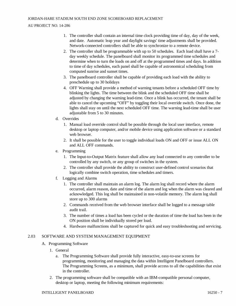
1. The controller shall contain an internal time clock providing time of day, day of the week,and date. Automatic leap year and daylight savings' time adjustments shall be provided.Network-connected controllers shall be able to synchronize to a remote device.
2. The controller shall be programmable with up to 50 schedules. Each load shall have a 7-day weekly schedule. The panelboard shall monitor its programmed time schedules anddetermine when to turn the loads on and off at the programmed times and days. In additionto time of day schedules, each panel shall be capable of astronomical scheduling fromcomputed sunrise and sunset times.
3. The panelboard controller shall be capable of providing each load with the ability topreschedule up to 30 holidays
4. OFF Warning shall provide a method of warning tenants before a scheduled OFF time byblinking the lights. The time between the blink and the scheduled OFF time shall beadjusted by changing the warning lead-time. Once a blink has occurred, the tenant shall beable to cancel the upcoming “OFF” by toggling their local override switch. Once done, thelights shall stay on until the next scheduled OFF time. The warning lead-time shall be useradjustable from 5 to 30 minutes.
d. Overrides1. Manual load override control shall be possible through the local user interface, remote
desktop or laptop computer, and/or mobile device using application software or a standardweb browser.
2. It shall be possible for the user to toggle individual loads ON and OFF or issue ALL ONand ALL OFF commands.
e. Programming1. The Input-to-Output Matrix feature shall allow any load connected to any controller to be
controlled by any switch, or any group of switches in the system.2. The controller shall provide the ability to construct user-defined control scenarios that
logically combine switch operation, time schedules and timers.f. Logging and Alarms
1. The controller shall maintain an alarm log. The alarm log shall record where the alarmoccurred, alarm reason, date and time of the alarm and log when the alarm was cleared andacknowledged. This log shall be maintained in non-volatile memory. The alarm log shallstore up to 300 alarms
2. Commands received from the web browser interface shall be logged to a message tableaudit trail.
3. The number of times a load has been cycled or the duration of time the load has been in theON position shall be individually stored per load.
4. Hardware malfunctions shall be captured for quick and easy troubleshooting and servicing.
2.03 SOFTWARE AND SYSTEM MANAGEMENT EQUIPMENT
A. Programming Software1. General
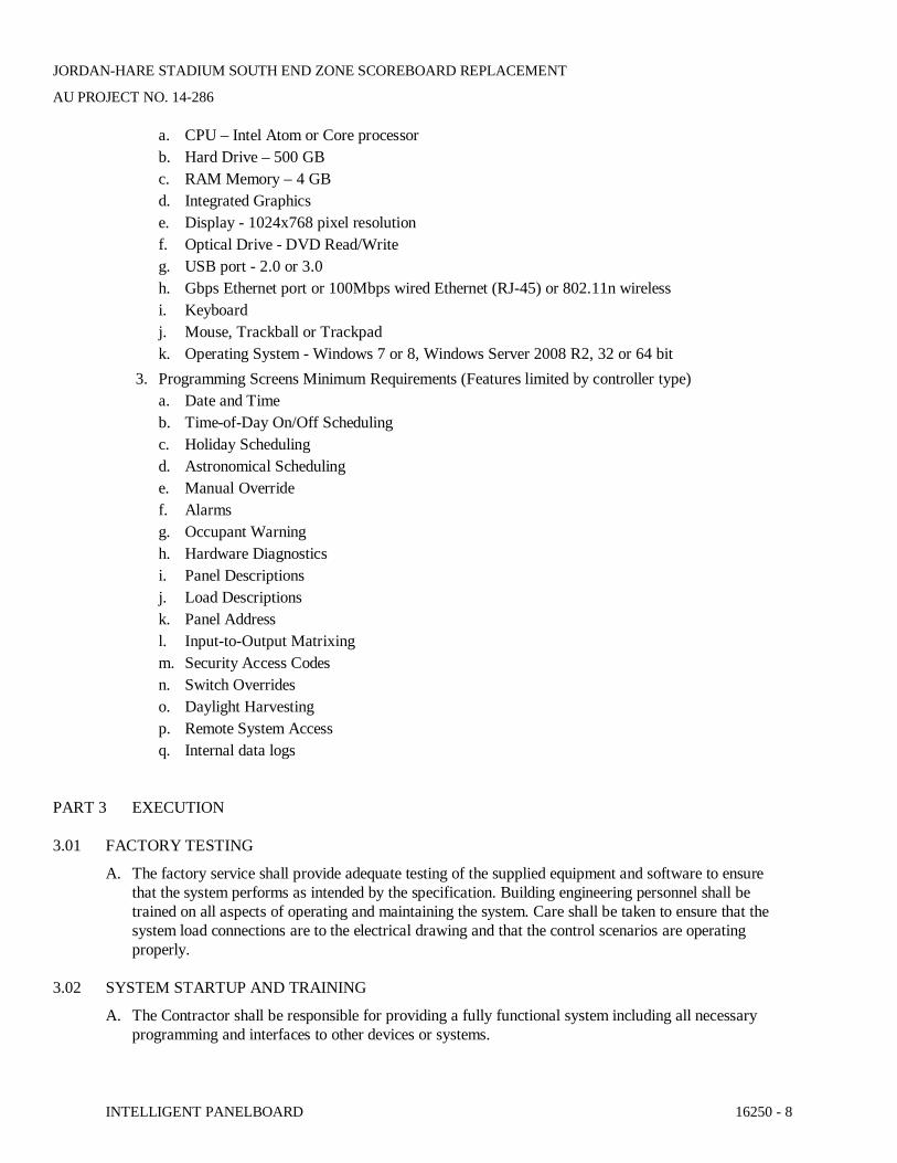
a. The Programming Software shall provide fully interactive, easy-to-use screens forprogramming, monitoring and managing the data within Intelligent Panelboard controllers.The Programming Screens, as a minimum, shall provide access to all the capabilities that existin the controller.
2. The programming software shall be compatible with an IBM-compatible personal computer,desktop or laptop, meeting the following minimum requirements:
JORDAN-HARE STADIUM SOUTH END ZONE SCOREBOARD REPLACEMENT
AU PROJECT NO. 14-286
INTELLIGENT PANELBOARD 16250 - 8
a. CPU – Intel Atom or Core processorb. Hard Drive – 500 GBc. RAM Memory – 4 GBd. Integrated Graphicse. Display - 1024x768 pixel resolutionf. Optical Drive - DVD Read/Writeg. USB port - 2.0 or 3.0h. Gbps Ethernet port or 100Mbps wired Ethernet (RJ-45) or 802.11n wirelessi. Keyboardj. Mouse, Trackball or Trackpadk. Operating System - Windows 7 or 8, Windows Server 2008 R2, 32 or 64 bit
3. Programming Screens Minimum Requirements (Features limited by controller type)a. Date and Timeb. Time-of-Day On/Off Schedulingc. Holiday Schedulingd. Astronomical Schedulinge. Manual Overridef. Alarmsg. Occupant Warningh. Hardware Diagnosticsi. Panel Descriptionsj. Load Descriptionsk. Panel Addressl. Input-to-Output Matrixingm. Security Access Codesn. Switch Overrideso. Daylight Harvestingp. Remote System Accessq. Internal data logs
PART 3 EXECUTION
3.01 FACTORY TESTING
A. The factory service shall provide adequate testing of the supplied equipment and software to ensurethat the system performs as intended by the specification. Building engineering personnel shall betrained on all aspects of operating and maintaining the system. Care shall be taken to ensure that thesystem load connections are to the electrical drawing and that the control scenarios are operatingproperly.
3.02 SYSTEM STARTUP AND TRAINING
A. The Contractor shall be responsible for providing a fully functional system including all necessaryprogramming and interfaces to other devices or systems.

JORDAN-HARE STADIUM SOUTH END ZONE SCOREBOARD REPLACEMENT
AU PROJECT NO. 14-286
INTELLIGENT PANELBOARD 16250 - 9
B. The Contractor shall meet with the owner’s representative to identify the desired system operation priorto system start-up.
C. Start-Up1. Manufacturer shall provide the services of a qualified factory-trained representative to assist the
Contractor in starting-up and programming the system for a minimum of 2 working days. Themanufacturer’s representative shall have a thorough knowledge of the software, hardware andsystem programming.
2. Manufacturer shall schedule and confirm start -up and training after receipt of a written start-uprequest and required project documentation.
3. The manufacturer’s representative shall provide the following services:a. Check installation of all Master Panelboards, Expansion Panelboards, central operator’s
station and other Intelligent Panelboard system components.b. Test operation of all remote-controlled loadsc. Test operation of all switch override control unitsd. Test operation of all digital and low voltage switchese. Test operation of all network connectionsf. Repair or replace any inoperative componentg. Test operation of complete Intelligent Panelboard systemh. Conduct system point-by-point walk through
4. Manufacturer shall provide a qualified factory trained representative to perform systemprogramming:a. Assist the owner in defining a practical control scenario for each areab. Assist Johnson Controls with their interface to the intelligent panelboards.c. Program the owner defined control scenariod. Explain the operation of the control programs to the owner and walk through their operatione. Provide programs on digital mediaAssist the BMS with their interface to the intelligent
panelboards5. Manufacturer shall certify in writing that the equipment has been installed, adjusted and tested in
accordance with the manufacturer’s recommendations.6. Manufacturer shall provide three (3) copies of the representative’s field startup report and
representative’s certification.
D. Training1. Manufacturer’s qualified factory trained representative shall provide a training session for up to
five (5) owner’s representatives for 1 1 normal workday at a jobsite location determined by theowner.
2. Training session provided by the manufacturer’s qualified factory-trained representative shallinclude instructions on the control system, programming, and other major components, including:a. System review of all system components and their functionb. System review of all management software and its functionc. Operator training to develop experience with control applications
3.03 INSTALLATION
A. The Contractor shall furnish, install and terminate all communication conductors and associatedconduits external to any factory supplied equipment.
JORDAN-HARE STADIUM SOUTH END ZONE SCOREBOARD REPLACEMENT
AU PROJECT NO. 14-286
INTELLIGENT PANELBOARD 16250 - 10
B. All communication conductor wiring and routing shall be per the manufacturer’s recommendations andas shown on the contract drawings.
3.04 FIELD TESTING
A. Verify complete system operation including all hardware, software and communication devices.
B. Verify networking performance with all interfacing systems by other manufacturers.
3.05 WARRANTY
A. The warranty shall ensure that the Lighting Control System manufactured and supplied as specifiedwill be the kind and quality described in the specification and will be free of defects in workmanshipand material.1. Warranty shall be 1 year from date of startup not to exceed 18 months from date of shipment2. Warranty shall be valid if startup is completed by factory-trained representative3. Warranty replacement parts shall be available on a 24-hour delivery basis, if requested during
normal working hours4. Warranty shall provide for on-site technical assistance if deemed necessary
END OF SECTION 16250
JORDAN-HARE STADIUM SOUTH END ZONE SCOREBOARD REPLACEMENTAU PROJECT NO. 14-286
LIGHTING 16500 - 1
SECTION 16500 - LIGHTING
PART 1 - GENERAL
1.1 SUMMARY
A. Provide lighting fixtures complete with all lamps as specified on the Electrical,Architectural, Interior and Lighting Designer Drawings. Provide all supports, brackets,connectors, materials, tools, wiring, controls and labor to provide a complete andoperating lighting system.
B. All blemished, damaged or unsatisfactory fixtures shall be replaced in a satisfactorymanner as directed by the Architect.
C. Where a fixture type designated has been omitted, cannot be determined or is in conflictwith other Drawings or Specifications, request a clarification from the Architect, prior tobid, and provide suitable fixture type as directed.
D. All lamps shall be operating at project completion and for a period of six (6) months afterthe final acceptance by the Owner.
E. Confirm exact locations of lighting fixtures with the Architectural Reflected Ceiling Planand mechanical equipment above or on the ceiling.
F. All recessed lighting fixtures shall match the ceiling type and be tested and certified bythe fixture manufacturer for the type of mounting.
1.2 PRODUCT DELIVERY, STORAGE AND HANDLING
A. Handle lighting fixtures carefully to prevent breakage, denting and scoring the fixturefinish. Do not install damaged lighting fixtures; replace and return damaged units toequipment Manufacturer.
B. Store lighting fixtures in clean, dry space. Store in original cartons and protect from dirt,physical damage, weather and construction traffic.
1.3 SUBMITTALS
A. The following submittal data shall be furnished according to Division 1 and Section16010 and shall include but not be limited to:1. Lighting fixtures complete with physical dimensions, materials, connector
details, voltage, current, installation details, air handling capability, etc.2. Lamps complete with base or pin configuration, lumen rating, life expectancy,
color temperature, starting characteristics, etc.
PART 2 - PRODUCTS
2.1 LIGHTING FIXTURES

JORDAN-HARE STADIUM SOUTH END ZONE SCOREBOARD REPLACEMENTAU PROJECT NO. 14-286
LIGHTING 16500 - 2
A. Base bid lighting fixtures shall be based on manufacturer and descriptions listed.Alternate fixture manufacturers not specified and proposed by the Contractor shall besubmitted for approval prior to base bid.
B. Fixtures are designated on the Drawings by “type” as indicated by a letter thatcorresponds to a lighting fixture description and specification on the lighting fixtureschedule.
C. Each lighting fixture shall comply with NEC Article 410, Energy Independence &Security Act, local codes and the authority having jurisdiction.
D. Provide a lighting fixture complete with lamps, ballasts and required accessories for eachlighting fixture shown. Provide all mounting and trim hardware to suit the specificinstallation and location.
E. All lighting fixtures shall bear a U.L. label.
F. Where fixtures are specified with acrylic lens, provide virgin acrylic with 0.125 inchthickness.
G. Exit lighting fixtures shall meet the requirements of all federal, state and local codes.
2.2 LAMPS
A. All lamps shall be as specified on the Lighting Fixture Schedule.
B. Fluorescent lamps in general shall be T8, 48-inch length with initial lumens of 2,950 at32 watts and an average life of 20,000 hours. If a color is not designated on theDrawings, then provide 3500K color lamps. Ballast and lamps shall be compatible.
C. Acceptable manufacturers are General Electric, Osram-Sylvania or Philips.
2.3 LAMP HOLDERS
A. For incandescent, provide porcelain body and nickel-plated brass socket, prelubricatedwith silicone compound.
B. For fluorescent, provide white urea plastic body and silver-plated phosphor bronze orberyllium copper contacts. Fluorescent lamp sockets with open-circuit voltage over 300volts shall be safety type and designed to open circuit when lamp is removed.
C. For compact fluorescent lamps, provide molded thermoplastic body with copper alloycontacts and stainless steel retainer clips. Provide pin configuration to match lamps.
D. For high intensity discharge, provide porcelain body and nickel-plated brass socket,prelubricated with silicone compound. Medium base sockets shall be 4 KV pulse rated.
2.4 BALLASTS
A. General
JORDAN-HARE STADIUM SOUTH END ZONE SCOREBOARD REPLACEMENTAU PROJECT NO. 14-286
LIGHTING 16500 - 3
1. All ballasts shall be UL listed and CBM certified. Ballasts shall be CSA certifiedwhere applicable.
2. Ballast shall be approved for operating with specified lamp. Ballast shall providenormal rated lamp life as stated by acceptable lamp manufacturer.
3. Ballast shall be suitable to operate on the voltage system they are connected toand maintain correct lamp operation with 10% fluctuation of rated input voltagewith no damage to ballasts or lamps.
4. Ballast shall have the lowest sound rating available for the lamps specified.Replace noisy ballasts as directed by Engineer at no cost to the Owner.
5. Ballast shall contain no PCBs.6. Ballasts shall be identical within each fixture type. All ballasts within the same
luminaire shall be from the same manufacturer.7. Ballast shall support a sustained short to ground on open circuit of any output
leads without damage to the ballast and without blowing fuses either inside theballast or in line with the ballast.
8. Ballast shall be suitable to operate in:a. Indoor heated or air conditioned spaces: 50ºF to 150ºF ambient.b. Outdoor or in unheated spaces: 0ºF to 105ºF.c. Un-air-conditioned spaces: 50ºF to 150ºF at rated life in pendant
mounted industrial type fixture.d. Recess mounted fixtures: in maximum 140ºF ceiling cavity.e. With fire-rated covering, clear air space between fixture and covering
minimum of 3 inches.9. Ballast for T-4 and T-5 lamps shall have lamp fault interrupter for end of life
failure.10. Manufacturer shall have been manufacturing ballasts for at least 5 years.
B. Fluorescent Ballast1. Ballast shall be high frequency and operate lamps at a frequency above 25 KHz
with less than 2% lamp flicker.2. Provide rapid start 0.99 power factor ballast, except as noted, with required
voltage and frequency.3. Ballast shall be UL listed Class P with integral resetting thermal protector, and be
suitable for use indoor or Type 1 outdoor application.4. Ballast case temperature shall not exceed 90ºC.5. Ballast shall have a ballast factor of greater than .875.6. Ballast shall comply with Federal Communications Commission Part 18C limits
for electromagnetic interference and radio frequency interference for non-consumer equipment.
7. Ballast shall provide transient immunity as specified by ANSI C62.41, CategoryA (formerly IEEE 587, Section B).
8. Ballast shall have lamp current crest factor of less than 1.7.9. Total harmonics distortion shall be less than 10%.10. Third harmonic distortion shall be less than 6%.11. Ballast shall internally limit in-rush current to not exceed 30 times normal
operating current for duration of 5 milliseconds.12. Manufacturer shall provide 5 year written warranty against defects in material or
workmanship, including replacement labor cost.13. Acceptable manufacturers are Magnetek, Motorola, Osram/Sylvania and
Advance.
JORDAN-HARE STADIUM SOUTH END ZONE SCOREBOARD REPLACEMENTAU PROJECT NO. 14-286
LIGHTING 16500 - 4
C. T-8 Electronic Fluorescent Dimming Ballast1. Ballast shall meet criteria for electronic fluorescent ballasts. See above.2. Smooth continuous dimming range from 100%-1%.3. Power factor greater than .90.4. Total harmonic distortion less than 20%.5. No visible lamp flicker over entire dimming range.6. Ballast shall be capable of striking lamps at any light level without first flashing
to 100% output.7. Ballast shall be UL listed for operating specified lamps.8. Ballast shall be inaudible over entire dimming range.9. Acceptable manufacturer is Lutron.
D. T-4 and T-5 Compact Fluorescent Electronic Dimming Ballast1. Ballast shall meet criteria for electronic fluorescent ballasts. See above.2. Smooth continuous dimming range from 100%-5%.3. Power factor greater than .90.4. Total harmonic distortion less than 20%.5. No visible lamp flicker over entire dimming range.6. Ballast shall be capable of striking lamps at any light level without first flashing
to 100% light output.7. Ballast shall be UL listed for operating specified lamps.8. Ballast shall be inaudible over entire dimming range.9. Acceptable manufacturer is Lutron.
E. High Intensity Discharge1. Provide constant wattage autotransformer (CWA) or high reactance
autotransformer high power factor (HX-HPF) type ballast with power factorgreater than .90 except as noted.
2. Ballast shall be designed with Class N insulation.3. Drop out voltage shall be not less than 70% of nominal.4. For indoor commercial application:
a. Provide NEMA rated AA@ sound rating.b. Ballast shall comply with Federal Communications Commission Part
18C limits for electromagnetic interference and radio frequencyinterference.
c. Ballast shall provide immunity as specified by ANSI C82-4.5. Acceptable manufacturers are Magnetek, Osram/Sylvania, Advance, and
Valmont.
2.5 EMERGENCY BATTERY LIGHTING
A. Lighting fixtures indicated on the drawings to be provided with an emergency batteryballast shall provide emergency lighting by using standard fluorescent lamp or lamps andan emergency battery ballast. The ballast shall consist of a field replaceable hightemperature, maintenance free nickel cadmium battery, charger and electronic circuitrycontained in one metal case. Provide a solid state charging indicator light to monitor thecharger and battery, double pole test switch and installation hardware. The battery ballastshall provide power to the fluorescent lamp upon failure of the normal supply to thefixture.

JORDAN-HARE STADIUM SOUTH END ZONE SCOREBOARD REPLACEMENTAU PROJECT NO. 14-286
LIGHTING 16500 - 5
B. The test button and indicator light shall be integral in the fixture reflector and shall bepositioned within or on the surface of the fixture so as to be accessible and identifiable.
C. Under normal mode the battery ballast shall keep the batteries at full charge. Upon lossof normal power the battery ballast shall operate the fluorescent lamp or lamps for 90minutes.
D. Battery recharge time shall not exceed 16 hours to fully recharge and shall not exceed225 milliamperes charging current.
E. The lumen output of the lamp or lamps powered by battery unit shall be not less than1100 lumens initially for a four foot fluorescent lamp.
F. The battery ballast shall meet or exceed all the requirements set forth in UL924“Emergency Lighting and Power Equipment” and shall be UL listed for installation ontop of or remote from the fixture. Emergency illumination shall meet or exceed therequirements set forth in the National Electric Code, Life Safety Code and UL 90-MinuteRequirements.
PART 3 - EXECUTION
3.1 GENERAL
A. Locations on the Drawings are diagrammatic. Verify exact locations with ArchitecturalReflected Ceiling Plans and coordinate space conditions with other trades.
B. Modify locations in mechanical equipment rooms to suit the conditions of the mechanicalequipment while maintaining a sufficient and uniform lighting level equal to thatprovided by the layout shown on the Drawings.
C. Fixtures of the same type and in the same ceiling shall have lamps, socket assembling anddoor hinges oriented in the same direction.
D. Reflector cones, baffles, aperture plates, light controlling element for air handling fixturesand decorative elements shall be installed after completion of ceiling tiles, painting andgeneral cleanup.
E. Target and focus adjustable lighting fixtures after regular working hours and beforebuilding acceptance. Permanently indicate targeting on fixture and provide positivelocking devices to preclude mis-focus relamping. Target and focus in the presence of theArchitect and Lighting Designer.
F. Relamp all incandescent and low-voltage fixtures immediately prior to Owner’sacceptance of building. Replace non-operating, damaged or darkened fluorescent andhigh intensity discharge lamps immediately to Owner’s acceptance of building.
G. Clean all fixture reflectors, lenses, louver, decorative accessories and lamps immediatelyprior to Owner’s acceptance of building. Destaticize plastic lenses and diffusers aftercleaning.

JORDAN-HARE STADIUM SOUTH END ZONE SCOREBOARD REPLACEMENTAU PROJECT NO. 14-286
LIGHTING 16500 - 6
H. Lighting fixtures mounted within, under, on or integral with millwork shall be givenspecial consideration. Fixture counting and sizes shall be coordinated with the applicablespace and adjusted accordingly. This coordination shall occur prior to ordering fixtures.Refer to Architectural Drawings for details.
3.2 SUPPORT OF LIGHT FIXTURES
A. Support directly from building structure, any lighting fixture which weighs in excess ofthe capacity of the suspended ceiling on which it is installed. Support each such fixturewith the quantity of threaded rods or fixture support wires required to prevent fixturewarping; however provide no less than two rods or wire per fixture.
B. Outlets, which are recessed in a suspended ceiling and support the weight of surface-mounted or suspended fixtures, shall be supported from a channel spanning and securedto the ceiling support system. Support each end of the channel with a fixture supportwire attached to structure.
C. Installation in grid-type suspended ceiling:1. Support each fixture at opposite corners, in which a lay-in fixture is located, with
a fixture support wire attached to structure to comply with NEC Art 410independent of any support provided from suspended ceiling grid. Provide asupport clip, securely fastened to the ceiling grid, at or near each corner of eachlay-in fixture.
2. Support fixtures, which are smaller than the ceiling grid opening and which arerecessed in the acoustical panel, with at least two metal channels spanning, andsecured to, the ceiling grid. Support each end of each channel or each corner ofthe grid opening with a fixture support wire attached to structure. Do not supportfixtures by ceiling acoustical panels.
D. Provide additional supports as required by local codes and seismic zone.
END OF SECTION 16500
JORDAN-HARE STADIUM SOUTH END ZONE SCOREBOARD REPLACEMENT
AU PROJECT NO. 14-286
ENERGY MANAGEMENT SYSTEM LIGHTING CONTROL 16900 - 1
SECTION 16900 - ENERGY MANAGEMENT SYSTEM LIGHTING CONTROL
PART 1 GENERAL
1.01 SCOPE
A. The Contractor shall connect the Lighting Control Panelboards as specified to the Johnson ControlsMetasys Energy Management System (EMS) as shown on the contract drawings.
B. The EMS work shall be indicated on the drawings and by the requirements of this section. It isdefined to include, but not limited to:1. Programming of Lighting Controls System on Campus Johnson Controls EMS2. Graphical representation of Lighting Controls.3. System startup and training of EMS.4. Coordinate all necessary interface requirements with the Lighting Controls System prior to
submittals and release of any equipment.
1.02 RELATED SECTIONS
A. Section 16200 – Service and Distribution
1.03 REFERENCES
A. NEMA Compliance: Comply with applicable portions of NEMA standards pertaining to types ofelectrical equipment and enclosures.
B. UL Listing: Lighting Control Panelboards shall be UL listed under UL 916 Energy ManagementEquipment, UL 67 Panelboard Interiors and UL 50 Panelboard Box.
C. NEC compliance: Comply with applicable portions of the NEC including Article 110-10.
D. California Title 24: All control equipment shall be California Title 24 compliant.
E. New York City Authority: All panelboards shall be certified for use in New York City by the NewYork City Authority.
F. FCC Emissions: All control equipment shall be in compliance with FCC emissions standards in Part15 Subpart J for Class A application.
1.04 SUBMITTALS – FOR REVIEW/APPROVAL/CONSTRUCTION
A. The following information shall be submitted to the Engineer:1. Interface to Lighting Controls system Network diagram.2. Point layout of system.3. Any sequence of applicable operation.4. Suggested lighting schedule.5. Product data sheets. Submit manufacturer’s data sheets on system submitted and components
supplied, with complete descriptions of hardware and software components supplied
B. Wiring Diagrams – All wiring to be furnished by the electrical contractor. Submit typical wiringdiagrams for all components including, but not limited to, smart panelboard, application specific
JORDAN-HARE STADIUM SOUTH END ZONE SCOREBOARD REPLACEMENT
AU PROJECT NO. 14-286
ENERGY MANAGEMENT SYSTEM LIGHTING CONTROL 16900 - 2
controllers, override switches, daylighting components, dimming ballasts, telephone lines, networkwiring, and the central operator’s station.
1.05 QUALIFICATIONS
A. The manufacturer of the assembly shall be the manufacturer of the major components within theassembly. Panelboards specified in this section shall be of the same manufacture as those specified inSection 26 24 00.
B. For the equipment specified herein, the manufacturer shall be ISO 9001 or 9002 certified.
C. The manufacturer of this equipment shall have produced similar electrical equipment for a minimumperiod of five (5) years. When requested by the Engineer, an acceptable list of installations withsimilar equipment shall be provided demonstrating compliance with this requirement.
D. The manufacturer of the lighting control panelboard shall be regularly engaged in manufacture ofelectrical distribution equipment, lighting control and/or energy management equipment of types andcapacities required and shall be the manufacturer of the remote controllable circuit breakers containedin the system.
1.06 REGULATORY REQUIREMENTS
A. The lighting control panelboard shall be labeled and listed under UL 916 Energy ManagementEquipment, UL 67 Panelboard Interiors and UL 50 Panelboard Box.
B. All control equipment shall be in compliance with FCC emissions' standards in Part 15 Subpart J forClass A application.
1.07 DELIVERY, STORAGE AND HANDLING
A. Equipment shall be handled and stored in accordance with manufacturer’s instructions. One (1) copyof these instructions shall be included with the equipment at time of shipment.
1.08 OPERATION AND MAINTENANCE MANUALS
A. Equipment operation and maintenance manuals shall be provided with each assembly shipped andshall include instruction leaflets, instruction bulletins and renewal parts lists where applicable, for thecomplete assembly and each major component.
PART 2 EXECUTION
2.01 FACTORY TESTING
A. The factory service shall provide adequate testing of the supplied equipment and software to ensurethat the system performs as intended by the specification. Building engineering personnel shall betrained on all aspects of operating and maintaining the system. Care shall be taken to ensure that thesystem load connections are to the electrical drawing and that the control scenarios are operatingproperly.
2.02 SYSTEM STARTUP AND TRAINING
A. The Contractor shall be responsible for providing a fully functional system including all necessaryprogramming and interfaces to other devices or systems.
JORDAN-HARE STADIUM SOUTH END ZONE SCOREBOARD REPLACEMENT
AU PROJECT NO. 14-286
ENERGY MANAGEMENT SYSTEM LIGHTING CONTROL 16900 - 3
B. The Contractor shall meet with the owner’s representative to identify the desired system operationprior to system start-up.
C. Start-Up1. EMS Contractor shall provide the services of a qualified factory-trained representative to assist
the Contractor in starting-up and programming the system for a minimum of 1 working day. Themanufacturer’s representative shall have a thorough knowledge of the software, hardware andsystem programming.
2. EMS Contractor shall schedule and confirm start -up and training after receipt of a written start-up request and required project documentation.
3. Manufacturer shall provide a qualified factory trained representative to perform systemprogramming:a. Assist the owner in defining a practical control scenario for each areab. Assist Lighting Contractor with their interface to the EMS.c. Program the owner defined control scenariod. Explain the operation of the control programs to the owner and walk through their operation
4. Manufacturer shall certify in writing that the equipment has been installed, adjusted and tested inaccordance with the manufacturer’s recommendations.
5. Manufacturer shall provide three (3) copies of the representative’s field startup report andrepresentative’s certification.
D. Training1. Manufacturer’s qualified factory trained representative shall provide a training session for up to
five (5) owner’s representatives for 1 normal workday at a jobsite location determined by theowner.
2. Training session provided by the manufacturer’s qualified factory-trained representative shallinclude instructions on the control system, programming, and other major components, including:a. System review of all system components and their functionb. System review of all management software and its functionc. Operator training to develop experience with control applications
2.03 FIELD TESTING
A. Verify complete system operation including all hardware, software and communication devices.
B. Verify networking performance with all interfacing systems by other manufacturers.
2.04 WARRANTY
A. The warranty shall ensure that the EMS as specified will be the kind and quality described in thespecification and will be free of defects in workmanship and material.1. Warranty shall be 1 year from date of startup not to exceed 18 months from date of shipment2. Warranty shall be valid if startup is completed by factory-trained representative3. Warranty replacement parts shall be available on a 24-hour delivery basis, if requested during
normal working hours4. Warranty shall provide for on-site technical assistance if deemed necessary
JORDAN-HARE STADIUM SOUTH END ZONE SCOREBOARD REPLACEMENT
AU PROJECT NO. 14-286
ENERGY MANAGEMENT SYSTEM LIGHTING CONTROL 16900 - 4
END OF SECTION 16900
Related Documents