Freescale Semiconductor Document Number: AN4869 Application Note Rev. 0, 03/2014 © Freescale Semiconductor, Inc., 2014. All rights reserved. _______________________________________________________________________ Sinusoidal Control of BLDCM with Hall Sensors Based on FRDM-KE04Z and Tower Board By: Liu Zhen 1 Introduction This application note describes the design of a 3-phase BLDC motor drive with Hall sensor based on sinusoidal waveform and Freescale’s FRDM-KE04Z. This application design takes the advantages of KE04Z peripherals for motor control. The application is a speed-close-loop drive using Hall sensors for positional detection. It serves as an example of a sensor BLDC motor control system by using one of the latest members of Freescale’s Kinetis and 3-Phase BLDC/PMSM Low-Voltage Motor Control Drive. It also illustrates the intelligible implementation of a BLDC motor control technique using Kinetis features. This application includes basic motor theory, system design concept, hardware implementation, and software design. It also includes the FreeMASTER visualization tool usage, application setup, and demo operation. Contents 1 Introduction 1 2 KE04 advantages and features 2 3 BLDC motor control theory 2 4 System design concept 4 5 Software design 15 6 Demo setup and operation 23 7 Debugging and conclusion 27 8 References 29

Welcome message from author
This document is posted to help you gain knowledge. Please leave a comment to let me know what you think about it! Share it to your friends and learn new things together.
Transcript

Freescale Semiconductor Document Number: AN4869
Application Note Rev. 0, 03/2014
© Freescale Semiconductor, Inc., 2014. All rights reserved.
_______________________________________________________________________
Sinusoidal Control of BLDCM with Hall
Sensors Based on FRDM-KE04Z and Tower
Board
By: Liu Zhen
1 Introduction
This application note describes the design of a
3-phase BLDC motor drive with Hall sensor
based on sinusoidal waveform and Freescale’s
FRDM-KE04Z. This application design takes the
advantages of KE04Z peripherals for motor
control.
The application is a speed-close-loop drive using
Hall sensors for positional detection. It serves as
an example of a sensor BLDC motor control
system by using one of the latest members of
Freescale’s Kinetis and 3-Phase BLDC/PMSM
Low-Voltage Motor Control Drive. It also
illustrates the intelligible implementation of a
BLDC motor control technique using Kinetis
features.
This application includes basic motor theory,
system design concept, hardware
implementation, and software design. It also
includes the FreeMASTER visualization tool
usage, application setup, and demo operation.
Contents
1 Introduction 1
2 KE04 advantages and features 2
3 BLDC motor control theory 2
4 System design concept 4
5 Software design 15
6 Demo setup and operation 23
7 Debugging and conclusion 27
8 References 29
Sinusoidal Control of BLDCM with Hall Sensors Based on FRDM-KE04Z and Tower Board, Rev. 0
2 Freescale Semiconductor
2 KE04 advantages and features
On-chip modules available within the family include the following features:
• Cortex™-M0+ core
• Up to 24 MHz CPU at 2.7–5.5 V
• 8 KB flash, 1 KB RAM
• Small size with 24 pins
• 12-bit ADC with 12 channels
• Analog comparator
• Periodic interrupt timer with 2 channels, FlexTimer module with 8 channels
• One 8-bit SPI module, one SCI/UART module, and one I2C module
• Up to 8 KBI interrupts
3 BLDC motor control theory
The brushless DC motor (BLDC Motor) is a rotating electric machine with a classic three-phase stator of
an induction motor; the rotor has surface-mounted permanent magnets. It is also referred to as an
electronically-commuted motor. There are no brushes on the rotor and the commutation is performed
electronically at certain rotor positions. The stator is usually made of magnetic steel sheets. A typical
cross-section of a BLDC Motor is shown in Figure 1. The stator-phase windings are inserted in the slots
(distributed winding) or they can be wound as one coil onto the magnetic pole. The rotor magnetic field is
constant, because the air-gap magnetic field is produced by permanent magnets.
Figure 1 BLDC motor/cross section
In this application, the BLDC motor is driven by sinusoidal voltage with given rotor position according to
Hall sensors, as depicted in Figure 2. This waveform is generated from Space Vector Modulation
Technique with O000 Null, as shown in Figure 3. This technology applies the voltage as shown in Figure 2

Sinusoidal Control of BLDCM with Hall Sensors Based on FRDM-KE04Z and Tower Board, Rev. 0
Freescale Semiconductor 3
to the 3-phase stator winding through the three phase inverter bridge, and then generates circular rotating
magnetic field with less torque ripple.
Figure 2 Voltage strokes applied to the 3-phase BLDC motor
Figure 3 Space vector modulation technique with O000 null-center-aligned PWM
For the common 3-phase BLDC motor, a standard 3-phase power stage used in this application design is
shown in Figure 4. The power stage utilizes six power transistors that operate in complementary mode in
this application.
0 0 60 120 180 240 300 360
1
Du
ty cycle ratio
0.8
0.6
0.48 0.2
Phase C Phase B Phase A
Sinusoidal Control of BLDCM with Hall Sensors Based on FRDM-KE04Z and Tower Board, Rev. 0
4 Freescale Semiconductor
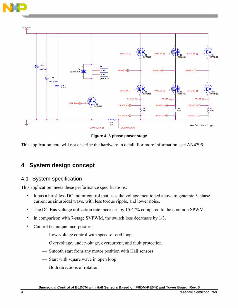
Figure 4 3-phase power stage
This application note will not describe the hardware in detail. For more information, see AN4796.
4 System design concept
4.1 System specification
This application meets these performance specifications:
• It has a brushless DC motor control that uses the voltage mentioned above to generate 3-phase
current as sinusoidal wave, with less torque ripple, and lower noise.
• The DC Bus voltage utilization rate increases by 15.47% compared to the common SPWM.
• In comparison with 7-stage SVPWM, the switch loss decreases by 1/3.
• Control technique incorporates:
— Low-voltage control with speed-closed loop
— Overvoltage, undervoltage, overcurrent, and fault protection
— Smooth start from any motor position with Hall sensors
— Start with square wave in open loop
— Both directions of rotation
Sinusoidal Control of BLDCM with Hall Sensors Based on FRDM-KE04Z and Tower Board, Rev. 0
Freescale Semiconductor 5
— Minimum speed of 300 rpm, and maximum speed of 3000 rpm
— Sinusoidal waveform of phase current on running stage
— FreeMASTER software-control interface (motor START/STOP, speed setup)
4.2 System drive concept
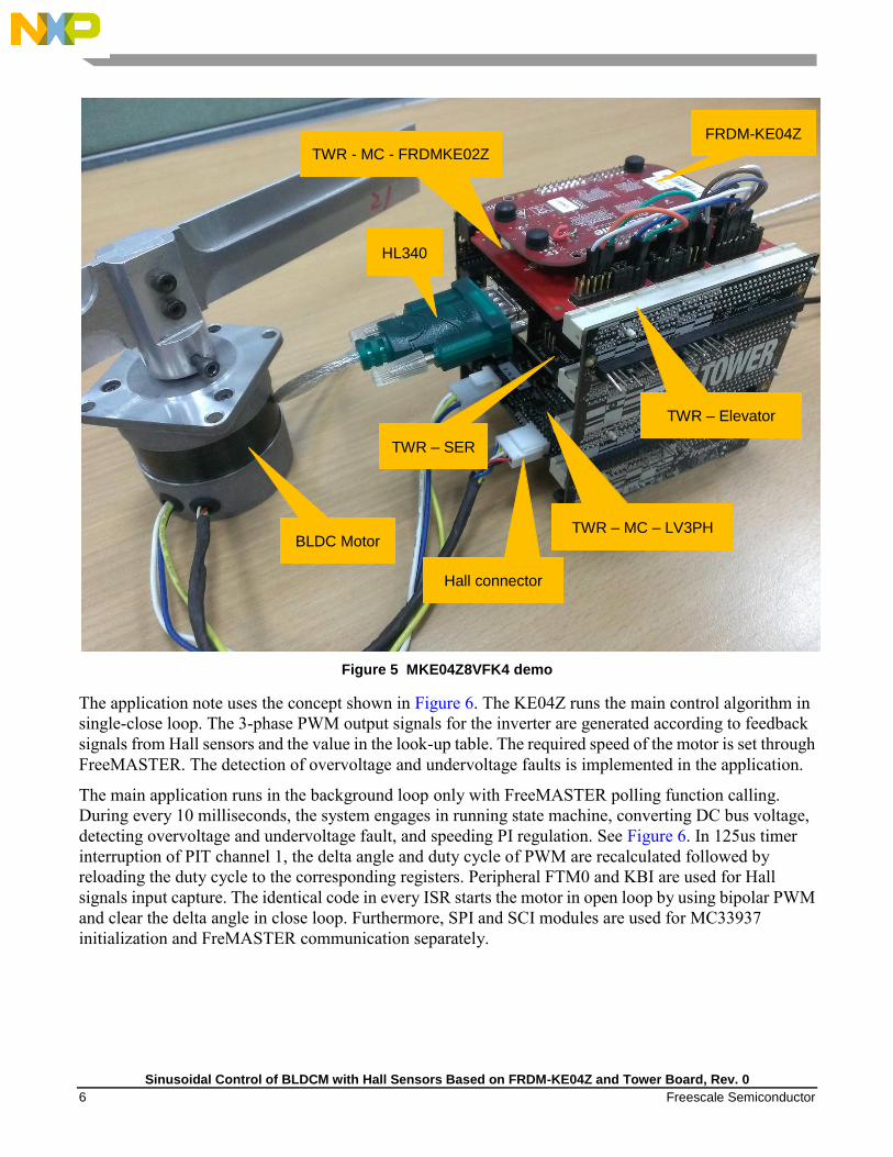
As shown in Figure 5, the system incorporates the following hardware:
• FRDM - KE04Z board
• TWR - MC - FRDMKE02Z board
• TWR - MC - LV3PH board
• TWR - SER board
• USB to serial cable HL-340
• Tower elevator
• BLDC motor (distribute winding) with Hall sensors
• Power Supply 24 V DC, 3.75 A
Detailed configuration of FRDM - KE04Z and TWR - MC - FRDMKE02Z board will be described in
Section 6.1 “Hardware Setup”.
Sinusoidal Control of BLDCM with Hall Sensors Based on FRDM-KE04Z and Tower Board, Rev. 0
6 Freescale Semiconductor
Figure 5 MKE04Z8VFK4 demo
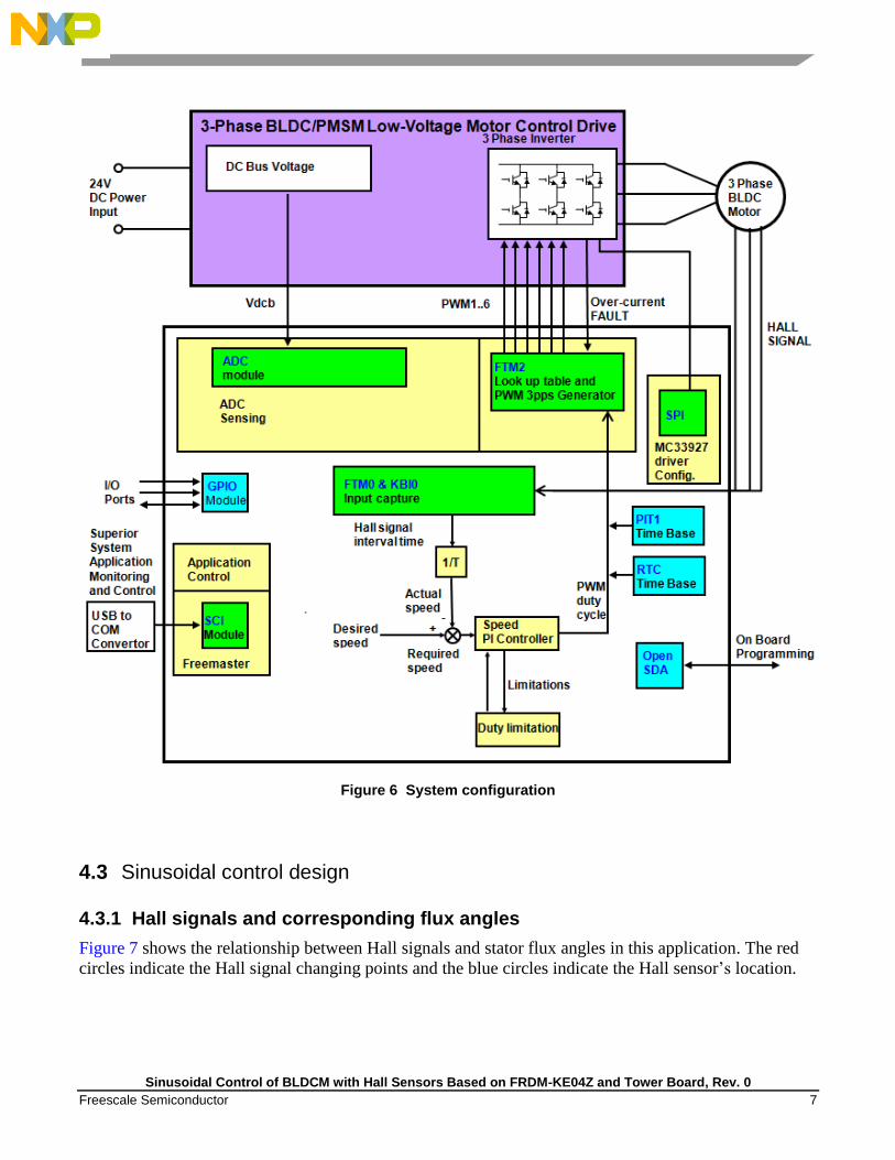
The application note uses the concept shown in Figure 6. The KE04Z runs the main control algorithm in
single-close loop. The 3-phase PWM output signals for the inverter are generated according to feedback
signals from Hall sensors and the value in the look-up table. The required speed of the motor is set through
FreeMASTER. The detection of overvoltage and undervoltage faults is implemented in the application.
The main application runs in the background loop only with FreeMASTER polling function calling.
During every 10 milliseconds, the system engages in running state machine, converting DC bus voltage,
detecting overvoltage and undervoltage fault, and speeding PI regulation. See Figure 6. In 125us timer
interruption of PIT channel 1, the delta angle and duty cycle of PWM are recalculated followed by
reloading the duty cycle to the corresponding registers. Peripheral FTM0 and KBI are used for Hall
signals input capture. The identical code in every ISR starts the motor in open loop by using bipolar PWM
and clear the delta angle in close loop. Furthermore, SPI and SCI modules are used for MC33937
initialization and FreMASTER communication separately.
FRDM-KE04Z
BLDC Motor
TWR - MC - FRDMKE02Z
TWR – SER
TWR – MC – LV3PH
TWR – Elevator
Hall connector
HL340
Sinusoidal Control of BLDCM with Hall Sensors Based on FRDM-KE04Z and Tower Board, Rev. 0
Freescale Semiconductor 7
Figure 6 System configuration
4.3 Sinusoidal control design
4.3.1 Hall signals and corresponding flux angles
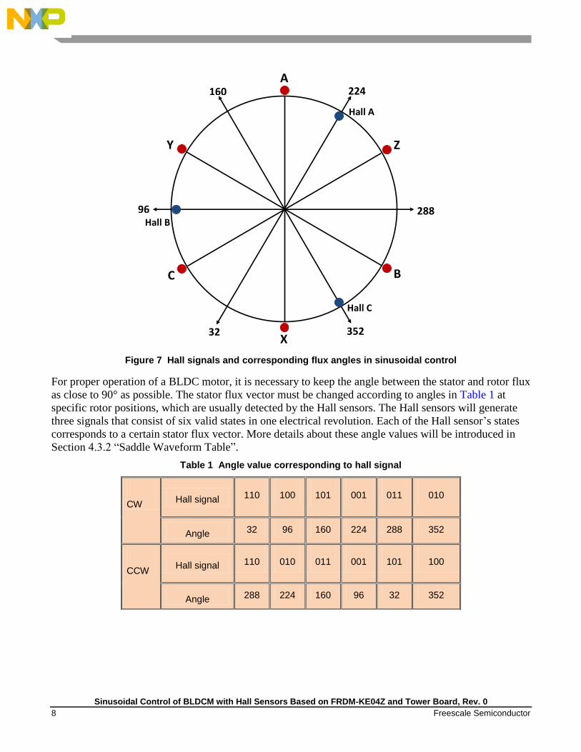
Figure 7 shows the relationship between Hall signals and stator flux angles in this application. The red
circles indicate the Hall signal changing points and the blue circles indicate the Hall sensor’s location.
Sinusoidal Control of BLDCM with Hall Sensors Based on FRDM-KE04Z and Tower Board, Rev. 0
8 Freescale Semiconductor
Figure 7 Hall signals and corresponding flux angles in sinusoidal control
For proper operation of a BLDC motor, it is necessary to keep the angle between the stator and rotor flux
as close to 90° as possible. The stator flux vector must be changed according to angles in Table 1 at
specific rotor positions, which are usually detected by the Hall sensors. The Hall sensors will generate
three signals that consist of six valid states in one electrical revolution. Each of the Hall sensor’s states
corresponds to a certain stator flux vector. More details about these angle values will be introduced in
Section 4.3.2 “Saddle Waveform Table”.
Table 1 Angle value corresponding to hall signal
CW Hall signal 110 100 101 001 011 010
Angle 32 96 160 224 288 352
CCW Hall signal 110 010 011 001 101 100
Angle 288 224 160 96 32 352
Z
C
Y
B
X
A
Hall C
Hall B
Hall A
32
96
160 224
352
288

Sinusoidal Control of BLDCM with Hall Sensors Based on FRDM-KE04Z and Tower Board, Rev. 0
Freescale Semiconductor 9
4.3.2 Saddle waveform table
Based on Figure 2, the saddle waveform table, named SinusoidalWaveTable, is used in this application
and created as below. The period of the waveform is set to 384 rather than 360, for the convenience of
calculation.
As shown in Figure 8, there is a part whose value keeps zero for one-third period of the waveform, so
switch loss can decrease by 1/3 compared to 7-stage SVPWM. static unsigned char SinusoidalWaveTable[384]=
127,131,135,138,142,145,149,152,155,159,162,165,168,171,174,177,180,183,186,189,192,194,197,200,
202,205,207,210, 212,214,217,219,221,223,225,227,229,231,232,234,236,237,239,240,242,243,244,245,
247,248,249,250,250,251,252,253,253,254,254,255,255,255,255,255,255,255,255,255,255,255,254,254,
253,253,252,252,251,250,249,248,247,246,245,244,242,241,240,238,237,235,233,232,230,228,226,224,
222,222,225,226,228,230,232,234,235,237,238,240,241,243,244,245,246,247,248,249,250,251,252,252,
253,254,254,254,255,255,255,255,255,255,255,255,255,255,254,254,254,253,252,252,251,250,249,248,
247,246,245,244,243,241,240,238,237,235,234,232,230,228,227,225,223,220,218,216,214,212,209,207,
204,202,199,197,194,191,188,185,183,180,177,174,171,167,164,161,158,154,151,148,144,141,137,134,
130,127,123,119,116,112,108,104,101, 97, 93, 89, 85, 81, 77, 73, 69, 65, 61, 57, 53, 49, 45, 41,
36, 32, 28, 24, 20, 16, 12, 7, 0, 0, 0, 0, 0, 0, 0, 0, 0, 0, 0, 0, 0, 0, 0, 0,
0, 0, 0, 0, 0, 0, 0, 0, 0, 0, 0, 0, 0, 0, 0, 0, 0, 0, 0, 0, 0, 0, 0, 0,
0, 0, 0, 0, 0, 0, 0, 0, 0, 0, 0, 0, 0, 0, 0, 0, 0, 0, 0, 0, 0, 0, 0, 0,
0, 0, 0, 0, 0, 0, 0, 0, 0, 0, 0, 0, 0, 0, 0, 0, 0, 0, 0, 0, 0, 0, 0, 0,
0, 0, 0, 0, 0, 0, 0, 0, 0, 0, 0, 0, 0, 0, 0, 0, 0, 0, 0, 0, 0, 0, 0, 0,
0, 0, 0, 0, 0, 0, 0, 0, 0, 0, 0, 0, 0, 0, 0, 0, 2, 6, 10, 15, 19, 23, 27, 31,
35, 39, 44, 48, 52, 56, 60, 64, 68, 72, 76, 80, 84, 88, 92, 96, 99,103,107,111,115,118,121,124
Figure 8 Saddle-shaped waveform used in the application
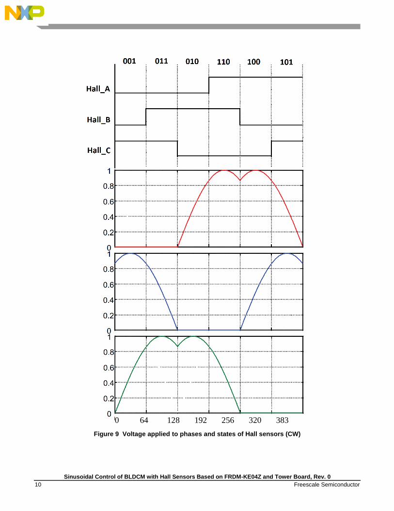
Figure 9 shows the relationship between the Hall signals and the voltage applied to 3-phase in this
application. Considering the saddle waveform table used in this application, the six states of Hall sensors
will correspond to 32o, 96
o, 160
o, 224
o, 288
o, and 352
o in clockwise order as mentioned in Table 1.
1
28
9
33
7
49
200
100
0
25
73
97
12
1 1
45
16
9
19
3
21
7 2
41
26
5
31
3
36
1
300
Sinusoidal Control of BLDCM with Hall Sensors Based on FRDM-KE04Z and Tower Board, Rev. 0
10 Freescale Semiconductor
Figure 9 Voltage applied to phases and states of Hall sensors (CW)
0 64 128 192 256 320 383

Sinusoidal Control of BLDCM with Hall Sensors Based on FRDM-KE04Z and Tower Board, Rev. 0
Freescale Semiconductor 11
4.3.3 Speed calculation
The actual speed of the motor is used by Speed PI Controller and delta angle calculation, which will be
described later. Optionally, the sector period is needed in the application of BLDC motor control with Hall
sensors. The sector period is the time between two consecutive Hall signal transitions. A sum of six
consecutive sector periods is equal to one revolution period, and this revolution is called electrical
revolution. The electrical revolution is related to the mechanical revolution through the number of motor
pole-pairs.
At a constant speed, each of the six sector periods may have a slightly different value, caused by an
angular error in the Hall sensor positions. In this application, Hall_C is the only signal used. The time
interval between two consecutive falling and rising edge of Hall_C indicates a half of electrical revolution.
Two pairs of BLDC motors are used in this application, with the scaled speed of 5000 rpm. Hence, T
method is used in motor speed calculation.
The actual speed value is calculated by using the following equation:
Equation 1
Where:
f [Hz] indicates the frequency of the CPU clock.
t indicates the time interval of Hall_C signal’s two consecutive edges.
4.3.4 delta angle estimation
In sinusoidal control mode, the angle used to control the motor should be continuous. However, as
mentioned in Section 4.3.1, there are only six angles according to the BLDC motor’s three Hall sensors,
and the other angles in motor’s running stage are not known. In this application, delta angle can be
calculated from the speed value by using the equation of tspeeddeltaAngle . In the term between
two Hall signals, the speed of the motor can be considered as stable and unchanged. Then these angles can
be calculated by adding or subtracting a delta angle to the angles that are obtained from Hall signals, as
shown by formula tspeeddeltaAngle . This process is shown in Figure 10. The delta angle is
calculated by using the following equation:
50003/)62(
32768128
60
max3/)6(
32768128
60
t
f
RpmtmotorPairs
f
speed

Sinusoidal Control of BLDCM with Hall Sensors Based on FRDM-KE04Z and Tower Board, Rev. 0
12 Freescale Semiconductor
124096100086032768
23845000
speed
speedspeed
Equation 2
Where:
The value of otableDotsN is 384. The delta angle calculation is used to avoid division and save
CPU resources.
Figure 10 delta angle calculation
4.3.5 Motor start
Before the motor begins to run, the primary position of the motor can be known according to Hall sensors’
outputs. However, there is no speed to calculate flux angles. Besides, the speed value varies greatly in the
start stage of the motor. Therefore, it is difficult to start the motor by using sinusoidal control mode
directly.
In this application, the 6-step control technique is used to start the motor. Bipolar PWM with the duty
cycle of 20% controls the voltage applied to the phases, and then the speed of the motor. See Figure 11.
Table 2 shows the vectors for clockwise rotation.
cyPITfrequen
motorPairsotableDotsNRpmspeeddeltaAngle
6032768
max

Sinusoidal Control of BLDCM with Hall Sensors Based on FRDM-KE04Z and Tower Board, Rev. 0
Freescale Semiconductor 13
Table 2 Clockwise start
Hall sensor
pattern result
Hall sensor pattern definition Commutation vector
OUTMASK
value
INVCTRL
value Hall A Hall B Hall C
6 1 1 0 A+, B- 0x0030 0x0002
4 1 0 0 A+, C- 0x000C 0x0004
5 1 0 1 B+, C- 0x0003 0x0004
1 0 0 1 B+, A- 0x0030 0x0001
3 0 1 1 C+, A- 0x000C 0x0001
2 0 1 0 C+, B- 0x0003 0x0002
After the motor starts successfully and the speed stabilizes, the sinusoidal control can be used. Here, the
time before sinusoidal control mode begins to work is set to one mechanical period. When sinusoidal
control mode is used, the duty cycle should be adjusted to keep speed and current smooth because of the
difference of flux generated in wye-connected windings in these two control modes. The modified duty
cycle should be 3/2 of the primary value.
Figure 11 6-step control with bipolar PWM
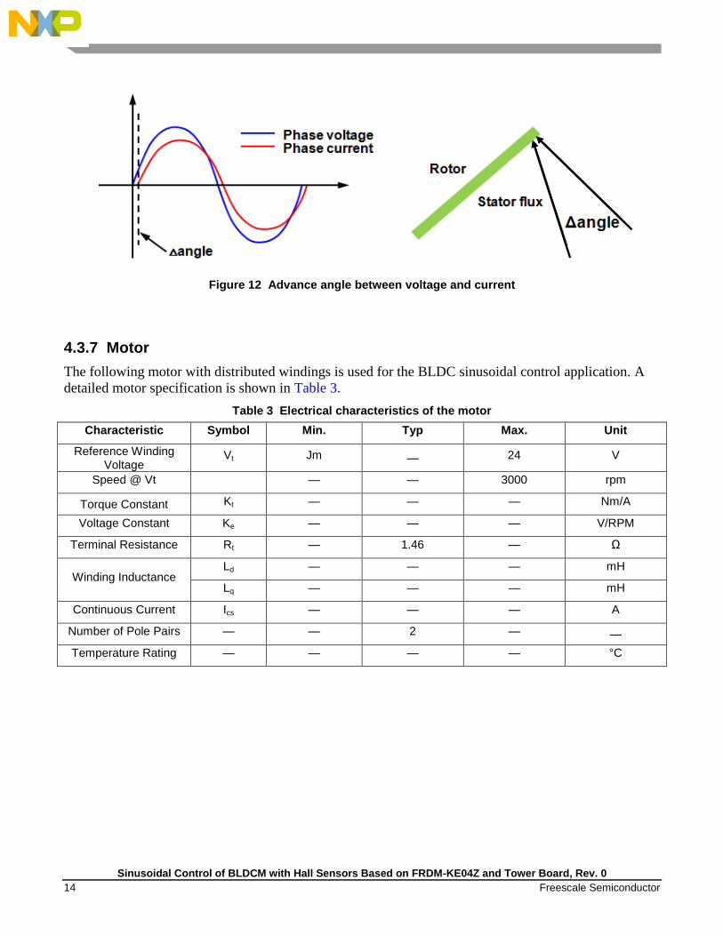
4.3.6 Advance angle calculation
The rotor angle is updated according to the Hall signals. In this case, the phase voltage is in phase with the
back EMF. However, due to motor’s inductive load, the phase current lags the phase voltage. The actual
angle between stator flux and rotor flux is not 90o, and the error grows as the speed increases. The phase
voltage needs to be adjusted to keep the angle as close to 90o as possible between stator flux angle and
rotor flux angle. This adjusted angle is called the advance angle. See Figure 12.
Sinusoidal Control of BLDCM with Hall Sensors Based on FRDM-KE04Z and Tower Board, Rev. 0
14 Freescale Semiconductor
Figure 12 Advance angle between voltage and current
4.3.7 Motor
The following motor with distributed windings is used for the BLDC sinusoidal control application. A
detailed motor specification is shown in Table 3.
Table 3 Electrical characteristics of the motor
Characteristic Symbol Min. Typ Max. Unit
Reference Winding Voltage
Vt Jm — 24 V
Speed @ Vt — — 3000 rpm
Torque Constant Kt — — — Nm/A
Voltage Constant Ke — — — V/RPM
Terminal Resistance Rt — 1.46 — Ω
Winding Inductance Ld — — — mH
Lq — — — mH
Continuous Current Ics — — — A
Number of Pole Pairs — — 2 — —
Temperature Rating — — — — °C
Sinusoidal Control of BLDCM with Hall Sensors Based on FRDM-KE04Z and Tower Board, Rev. 0
Freescale Semiconductor 15
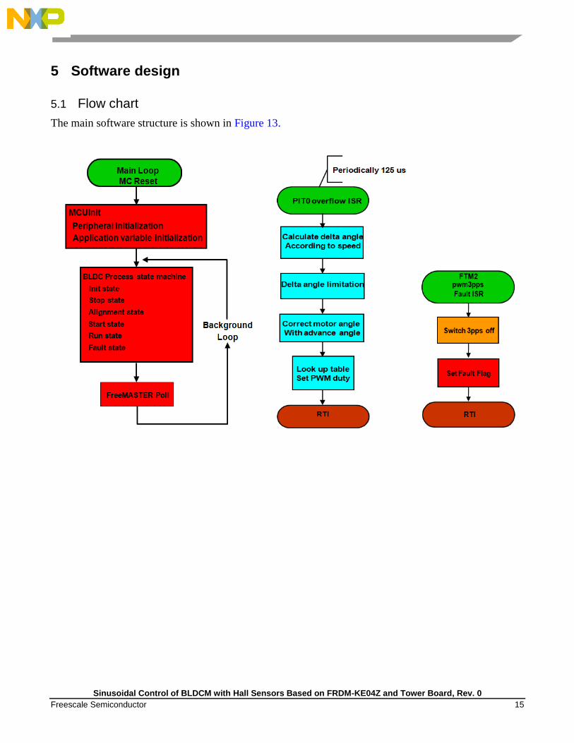
5 Software design
5.1 Flow chart
The main software structure is shown in Figure 13.
Sinusoidal Control of BLDCM with Hall Sensors Based on FRDM-KE04Z and Tower Board, Rev. 0
16 Freescale Semiconductor
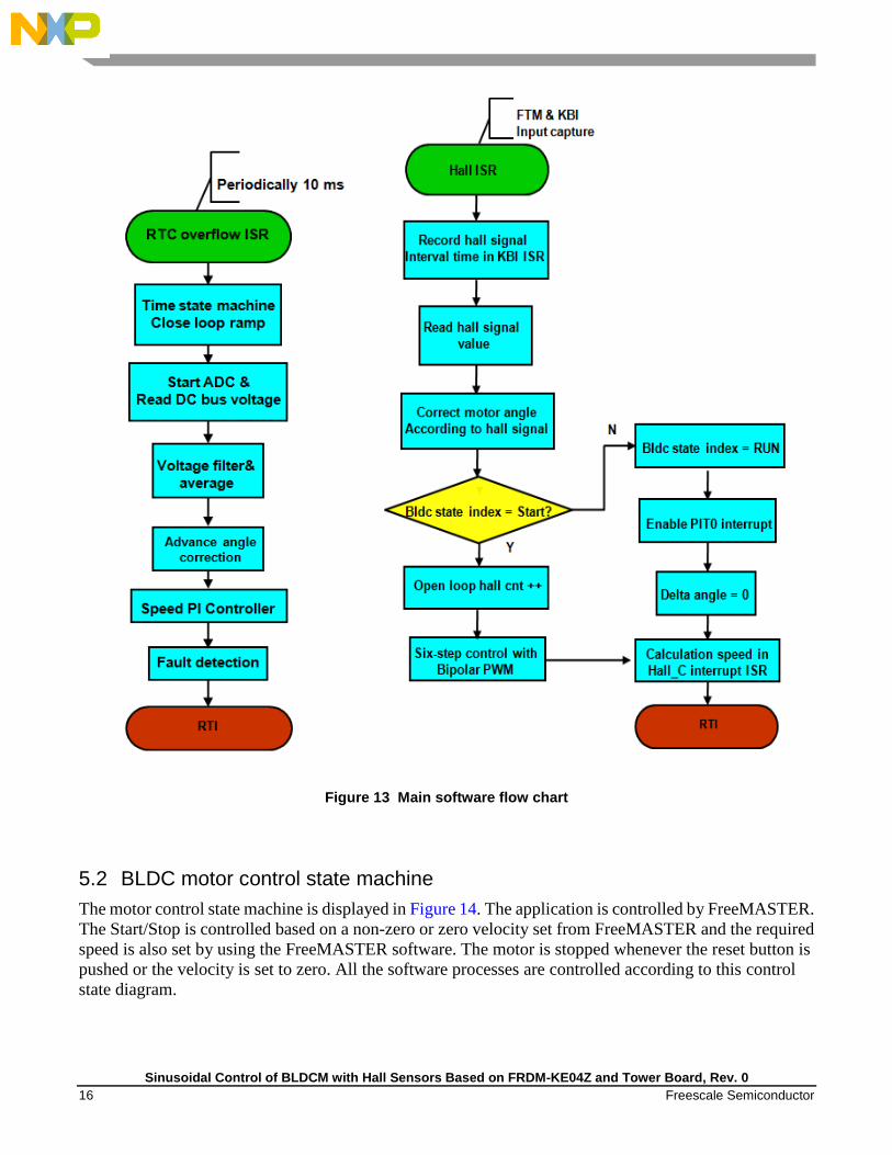
Figure 13 Main software flow chart
5.2 BLDC motor control state machine
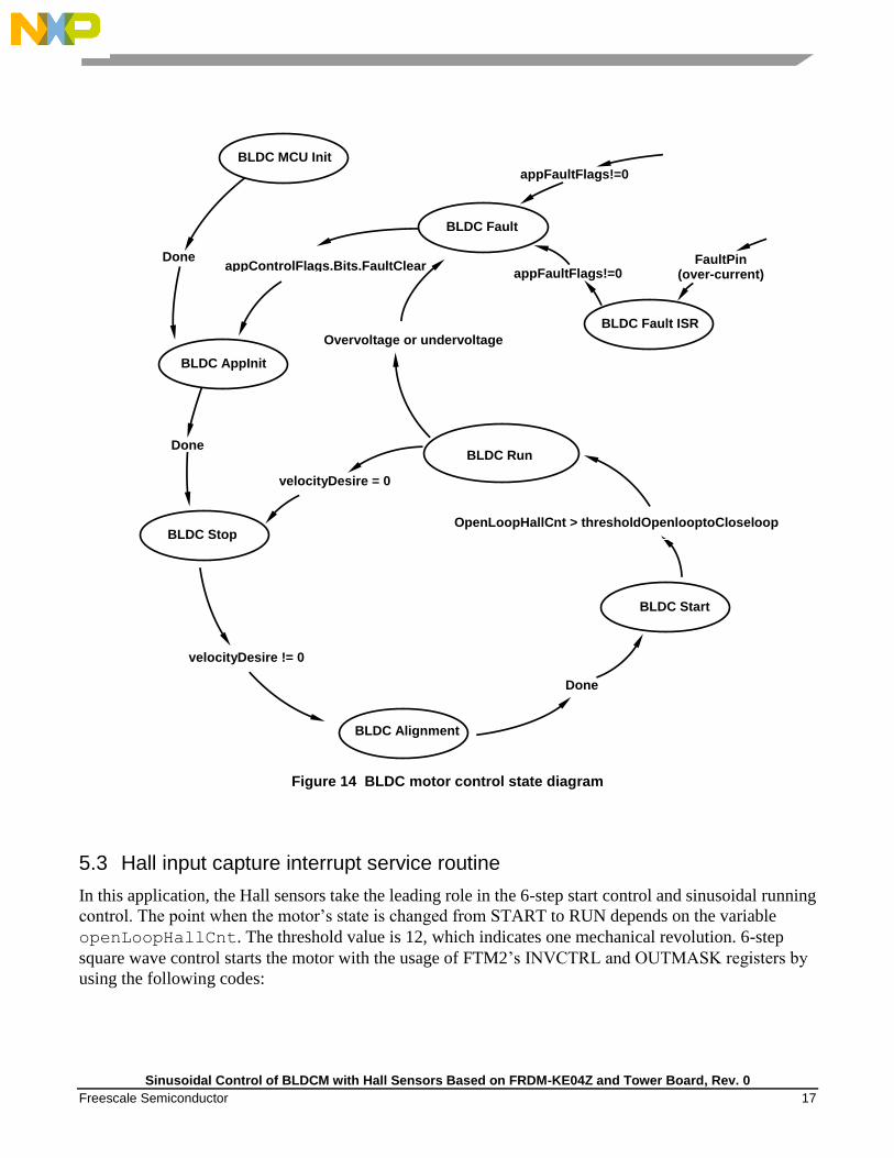
The motor control state machine is displayed in Figure 14. The application is controlled by FreeMASTER.
The Start/Stop is controlled based on a non-zero or zero velocity set from FreeMASTER and the required
speed is also set by using the FreeMASTER software. The motor is stopped whenever the reset button is
pushed or the velocity is set to zero. All the software processes are controlled according to this control
state diagram.
Sinusoidal Control of BLDCM with Hall Sensors Based on FRDM-KE04Z and Tower Board, Rev. 0
Freescale Semiconductor 17
Figure 14 BLDC motor control state diagram
5.3 Hall input capture interrupt service routine
In this application, the Hall sensors take the leading role in the 6-step start control and sinusoidal running
control. The point when the motor’s state is changed from START to RUN depends on the variable
openLoopHallCnt. The threshold value is 12, which indicates one mechanical revolution. 6-step
square wave control starts the motor with the usage of FTM2’s INVCTRL and OUTMASK registers by
using the following codes:
BLDC MCU Init
BLDC AppInit
BLDC Stop
BLDC Alignment
BLDC Start
BLDC Run
BLDC Fault
BLDC Fault ISR
appControlFlags.Bits.FaultClear
Done
velocityDesire != 0
Done
Done
Overvoltage or undervoltage
FaultPin (over-current)
appFaultFlags!=0
appFaultFlags!=0
velocityDesire = 0
OpenLoopHallCnt > thresholdOpenlooptoCloseloop
Sinusoidal Control of BLDCM with Hall Sensors Based on FRDM-KE04Z and Tower Board, Rev. 0
18 Freescale Semiconductor
openLoopHallCnt++;
PWMState = bldcCommutationTableComp[motorPosition];
if (PWMState.swap & 1)
FTM2->INVCTRL |= FTM_INVCTRL_INV0EN_MASK;
else
FTM2->INVCTRL &= ~FTM_INVCTRL_INV0EN_MASK;
if (PWMState.swap & 2)
FTM2->INVCTRL |= FTM_INVCTRL_INV1EN_MASK;
else
FTM2->INVCTRL &= ~FTM_INVCTRL_INV1EN_MASK;
if (PWMState.swap & 4)
FTM2->INVCTRL |= FTM_INVCTRL_INV2EN_MASK;
else
FTM2->INVCTRL &= ~FTM_INVCTRL_INV2EN_MASK;
FTM2->OUTMASK = PWMState.mask; // Update FTM registers
FTM2->SYNC |= FTM_SYNC_REINIT_MASK; // Update FTM registers
In the interrupt service routine of each Hall sensor, the rotor position should be updated through reading
the pins’ input signals directly. The following codes are presented in Hall_C ISR, and the same in Hall_A
and Hall_B.
hallC = GPIOA->PDIR;
hallC = ((hallC >>3) >> 8) >> 8;//PTC3
hallC = hallC & 1;// status of hallC
bldcIntHallFlags.Byte = (char)( hallA | hallB | hallC);
motorPosition = (bldcIntHallFlags.Byte & 0x07);
The speed is also calculated in Hall interrupt service routine, but it is only calculated in Hall_C ISR in this
application. The FTM0 module is used to save the time information for speed calculation.
CalTimePrevious = CalTime;
CalTime = (tU16)FTM0->CNT;
TimeInterval = CalTime - CalTimePrevious; //calculate half
CalculationSpeed(); electronic cycle time
Because of the limitation of the MCU’s peripherals and pins, KBI is used to capture one of three Hall
sensors’ output signals. In every Hall ISR, the bit KBI1->ES should be toggled to capture next coming
edge due to the feature of KE04’s KBI. The two registers, INVCTRL and OUTMASK mentioned above,
should be cleared after motor’s state changes to Run to ensure that the motor can run properly in sinusoidal
control mode.
Sinusoidal Control of BLDCM with Hall Sensors Based on FRDM-KE04Z and Tower Board, Rev. 0
Freescale Semiconductor 19
5.4 PIT – delta angle calculation interrupt service routine
Flux angle is calculated and updated in PIT chanel1’s ISR every 125us. From Section 4.2.3, it is known
that the flux angle has direct proportional relationship with velocity. Between two Hall signals, variable
mtrAngle represents flux angle in real time. When the motor rotates in clockwise direction, the angle is
computed as follows:
deltaAngle = F32Add(deltaAngle,F32Abs(velocityAct));
if (deltaAngle >= DELTANGLE_MAX) //limit deltaAngle range into
[0,64]
deltaAngle = DELTANGLE_MAX;
mtrAngle = HallTableCW[motorPosition];
mtrAngle += (tU16)((deltaAngle) >> 12);
mtrAngle += (tU16)advanceAngle;
if (mtrAngle >= 384)
mtrAngle -= 384;
If the motor rotates in counter clockwise direction, the codes are shown below:
deltaAngle = F32Add(deltaAngle,F32Abs(velocityAct));
if (deltaAngle >= DELTANGLE_MAX) //limit deltaAngle range into
[0,64]
deltaAngle = DELTANGLE_MAX;
mtrAngle = HallTableCCW[motorPosition];
mtrAngle -= (tU16)((deltaAngle) >> 12);
mtrAngle += (tU16)advanceAngle;
if (mtrAngle >= 384)
mtrAngle = 384;
After the flux angle mtrAngle is calculated, the dutycycles of three phases can also be calculated by using
the codes below:
dutyCycleU16A = (Frac16)(((Frac16)dutyCycleU16 *
(Frac16)SinusoidalWaveTable[mtrAngle]) >> 8);
if (mtrAngle < 128)
dutyCycleU16B = (Frac16)(((Frac16)dutyCycleU16 *
(Frac16)SinusoidalWaveTable[mtrAngle + 256]) >> 8);
else
Sinusoidal Control of BLDCM with Hall Sensors Based on FRDM-KE04Z and Tower Board, Rev. 0
20 Freescale Semiconductor
dutyCycleU16B = (Frac16)(((Frac16)dutyCycleU16 *
(Frac16)SinusoidalWaveTable[mtrAngle - 128]) >> 8);
if (mtrAngle >= 256)
dutyCycleU16C = (Frac16)(((Frac16)dutyCycleU16 *
(Frac16)SinusoidalWaveTable[mtrAngle -256]) >> 8);
else
dutyCycleU16C = (Frac16)(((Frac16)dutyCycleU16 *
(Frac16)SinusoidalWaveTable[mtrAngle + 128]) >> 8);
5.5 Configurations
5.5.1 MOSFET driver configuration
For the correct operation of the MC33937, the predriver should be configured through SPI
communication. There are two more files, providing SPI communication between the MCU and the
predriver.
• The spi_comm.h header file contains configuration and status constants defined for the MC33937
driver.
• The spi_comm.c file contains SPI communication functions and configuration function for the
MC33937 driver.
The SPI communication is used not only for driver configuration, but also for diagnosing this driver.
5.5.2 PWM generation and timer
The KE04Z64VQH2’s FTM module has two submodules. FTM2 generates six PWM signals to drive the
MC33937 and FTM0 is configured for inputting capture function to detect the Hall signals. The six
generated PWM signals drive the MOSFETs of the 3-phase inverter bridge through MC33937. The FTM2
is configured as follows:
FTM2
• System clock source
FTM2->SC |= FTM_SC_CLKS(1);
• Generates PWM with running frequency of 16 kHz
• Modulo 1500 with 0.067% resolution

Sinusoidal Control of BLDCM with Hall Sensors Based on FRDM-KE04Z and Tower Board, Rev. 0
Freescale Semiconductor 21
FTM2->MOD = PWM_MODULO; (#define PWM_MODULO 1500)
• Combines and complements mode with the deadtime of s1
FTM2->COMBINE = FTM_COMBINE_FAULTEN0_MASK
| FTM_COMBINE_SYNCEN0_MASK | FTM_COMBINE_DTEN0_MASK
| FTM_COMBINE_COMP0_MASK | FTM_COMBINE_COMBINE0_MASK
| FTM_COMBINE_FAULTEN1_MASK
| FTM_COMBINE_SYNCEN1_MASK | FTM_COMBINE_DTEN1_MASK
| FTM_COMBINE_COMP1_MASK | FTM_COMBINE_COMBINE1_MASK
| FTM_COMBINE_FAULTEN2_MASK
| FTM_COMBINE_SYNCEN2_MASK | FTM_COMBINE_DTEN2_MASK
| FTM_COMBINE_COMP2_MASK |FTM_COMBINE_COMBINE2_MASK;
FTM2->DEADTIME = FTM_PWM_DEAD_TIME;
( #define FTM_PWM_DEAD_TIME 24 )
• High-side switch PWM_T output in low polarity
• Low-side switch PWM_B output in high polarity
FTM2->POL = FTM2POL_INIT ;
( #define FTM2POL_INIT FTM_POL_POL0_MASK | FTM_POL_POL2_MASK |
FTM_POL_POL4_MASK )
FTM2 fault
• High-level on fault input pin1 indicates a fault signal.
• High-side PWM signals are set to high-level when a fault signal is detected.
• Low-side PWM signals are set to low-level when a fault signal is detected.
• Fault input filter is disabled.
FTM2->FLTCTRL |= FTM_FLTCTRL_FAULT1EN_MASK;
FTM2->MODE |= FTM_MODE_FAULTM(2) | FTM_MODE_FAULTIE_MASK;
The BLDC motor uses the RTC module and one PIT module (PIT1) to generate periodic interrupt. One is
used as speed loop regulator timebase and the other is used to calculate flux angle periodically.
RTC
·Runs at frequency 187.5 kHz.
RTC->SC |= RTC_SC_RTCLKS(3) | RTC_SC_RTCPS(1);
·Generates 10ms interrupt.
RTC->MOD = RTC_MOD_MOD(0x753-0x01);
Sinusoidal Control of BLDCM with Hall Sensors Based on FRDM-KE04Z and Tower Board, Rev. 0
22 Freescale Semiconductor
PTI
• Runs at frequency 24 MHz.
PIT->MCR = 0x00;
• Counts up until compare and reinitializes.
PIT->CHANNEL[1].TCTRL = 0x03;
• Generates 3ms interrupt with modulo value 0xBB8.
PIT->CHANNEL[1].LDVAL = (0xBB8-0x01);
5.5.3 Hall signals capture
In this application, the two channels of FTM0 and pin5 of KBI1 are used to capture the Hall sensors’
output signals. They are configured as follows:
FTM0
• System clock source is divided by 128.
FTM0->SC |= FTM_SC_CLKS(1) | FTM_SC_PS(7);
• Interrupts with rising and falling edge coming.
FTM0->CONTROLS[0].CnSC |= FTM_CnSC_ELSA_MASK |
FTM_CnSC_ELSB_MASK;
FTM0->CONTROLS[1].CnSC |= FTM_CnSC_ELSA_MASK |
FTM_CnSC_ELSB_MASK;
• Selects pin PTB2 and PTB3 used by FTM0.
SIM->PINSEL |= SIM_PINSEL_FTM0PS0_MASK | SIM_PINSEL_FTM0PS1_MASK;
KBI1
• Disables interrupt before configuration.
KBI1->SC &= ~KBI_SC_KBIE_MASK;
• Enables Pullup for port C bit 3.
PORT->PUEL |= PORT_PUEL_PTCPE3_MASK;
• Pin5 is enabled as KBI interrupt.
KBI1->PE |= 0x20;
• Writes a 1 to KBACK to clear the flag.
KBI1->SC |= KBI_SC_KBACK_MASK;
Sinusoidal Control of BLDCM with Hall Sensors Based on FRDM-KE04Z and Tower Board, Rev. 0
Freescale Semiconductor 23
5.5.4 AD conversion
The ADC module is started in RTC’s ISR by using polling and is configured for DC_Bus voltage
conversion as follows:
• Single conversion mode.
ADC->SC1 &= ~ADCADC_SC1_ADCO_MASK;
• Right-justified result data with 12-bit resolution, 3MHz for AD conversion clock.
ADC->SC3 = ADC_SC3_MODE(2) | ADC_SC3_ADIV(3);
• Selects software trigger.
ADC->SC2 &= ~ADC_SC2_ADTRG_MASK;
• Enables channel 10 for DC_Bus voltage sample.
ADC->APCTL1 = 0x4000;
6 Demo setup and operation
For demonstrating the operation, this demo is built and available for customers.
6.1 Hardware setup
The hardware is shown in Figure 6. Perform the following steps to run the BLDC motor.
1. Plug the power supply jack connector to the low-voltage motor control board connector J1.
2. Connect the USB 2.0 cable to the PC and to the KE04Z central control board connector J6.
3. Check the settings on the KE04Z central control board.
o J9, J10, and J5 used for debug convenience must be shorted.
o Remove the resistors R15, R16, R19, R31, R37, R40, R43, R46, R51, R52, R53, R66, R67,
R70, R71 and R75.
o Add resistors R4, R17, R18, R39, R42, R45, R47, R50, R61, R64, R69, R72 and R73.
o Change resistors R6, R7 and R3 to zero Ohm.
o Remove capacitors C5, C6 and C2 and add capacitor C3 (2200pF).
Sinusoidal Control of BLDCM with Hall Sensors Based on FRDM-KE04Z and Tower Board, Rev. 0
24 Freescale Semiconductor
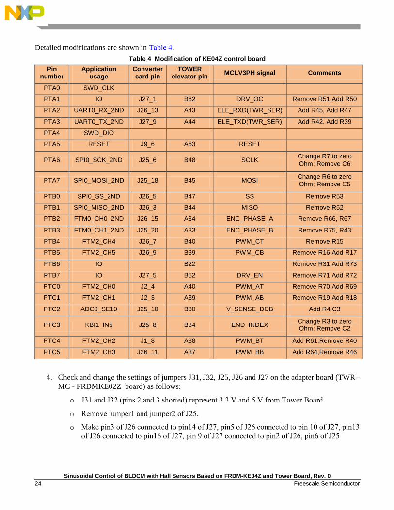
Detailed modifications are shown in Table 4.
Table 4 Modification of KE04Z control board
Pin number
Application usage
Converter card pin
TOWER elevator pin
MCLV3PH signal Comments
PTA0 SWD_CLK
PTA1 IO J27_1 B62 DRV_OC Remove R51,Add R50
PTA2 UART0_RX_2ND J26_13 A43 ELE_RXD(TWR_SER) Add R45, Add R47
PTA3 UART0_TX_2ND J27_9 A44 ELE_TXD(TWR_SER) Add R42, Add R39
PTA4 SWD_DIO
PTA5 RESET J9_6 A63 RESET
PTA6 SPI0_SCK_2ND J25_6 B48 SCLK Change R7 to zero Ohm; Remove C6
PTA7 SPI0_MOSI_2ND J25_18 B45 MOSI Change R6 to zero Ohm; Remove C5
PTB0 SPI0_SS_2ND J26_5 B47 SS Remove R53
PTB1 SPI0_MISO_2ND J26_3 B44 MISO Remove R52
PTB2 FTM0_CH0_2ND J26_15 A34 ENC_PHASE_A Remove R66, R67
PTB3 FTM0_CH1_2ND J25_20 A33 ENC_PHASE_B Remove R75, R43
PTB4 FTM2_CH4 J26_7 B40 PWM_CT Remove R15
PTB5 FTM2_CH5 J26_9 B39 PWM_CB Remove R16,Add R17
PTB6 IO
B22
Remove R31,Add R73
PTB7 IO J27_5 B52 DRV_EN Remove R71,Add R72
PTC0 FTM2_CH0 J2_4 A40 PWM_AT Remove R70,Add R69
PTC1 FTM2_CH1 J2_3 A39 PWM_AB Remove R19,Add R18
PTC2 ADC0_SE10 J25_10 B30 V_SENSE_DCB Add R4,C3
PTC3 KBI1_IN5 J25_8 B34 END_INDEX Change R3 to zero Ohm; Remove C2
PTC4 FTM2_CH2 J1_8 A38 PWM_BT Add R61,Remove R40
PTC5 FTM2_CH3 J26_11 A37 PWM_BB Add R64,Remove R46
4. Check and change the settings of jumpers J31, J32, J25, J26 and J27 on the adapter board (TWR -
MC - FRDMKE02Z board) as follows:
o J31 and J32 (pins 2 and 3 shorted) represent 3.3 V and 5 V from Tower Board.
o Remove jumper1 and jumper2 of J25.
o Make pin3 of J26 connected to pin14 of J27, pin5 of J26 connected to pin 10 of J27, pin13
of J26 connected to pin16 of J27, pin 9 of J27 connected to pin2 of J26, pin6 of J25
Sinusoidal Control of BLDCM with Hall Sensors Based on FRDM-KE04Z and Tower Board, Rev. 0
Freescale Semiconductor 25
connected to pin8 of J27, pin8 of J25 connected to pin14 of J26, pin10 of J25 connected to
pin17 of J25, pin18 of J25 connected to pin12 of J27.
Detailed modifications are shown in Table 5.
Table 5 Pin connections modified for adapter board
J26_13 <---> J27_16
J27_9 <---> J26_2
J25_6 <---> J27_8
J25_18 <---> J27_12
J26_5 <---> J27_10
J26_3 <---> J27_14
J25_10 <---> J25_17
J25_8 <---> J26_14
J26_11 <---> J26_12
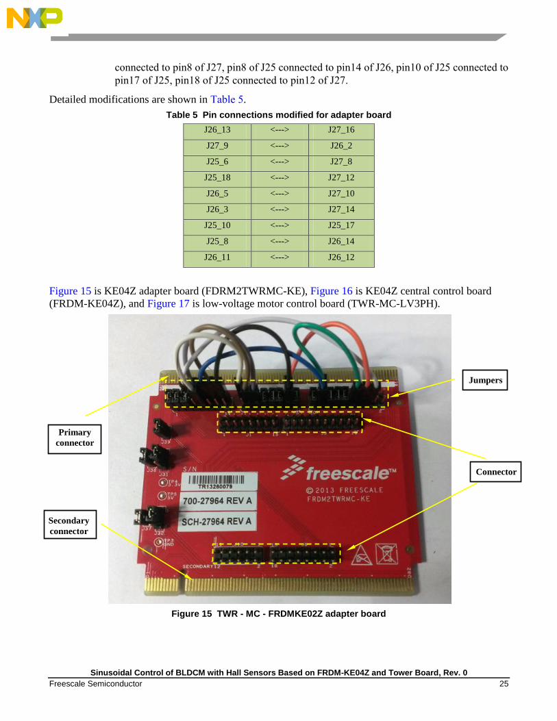
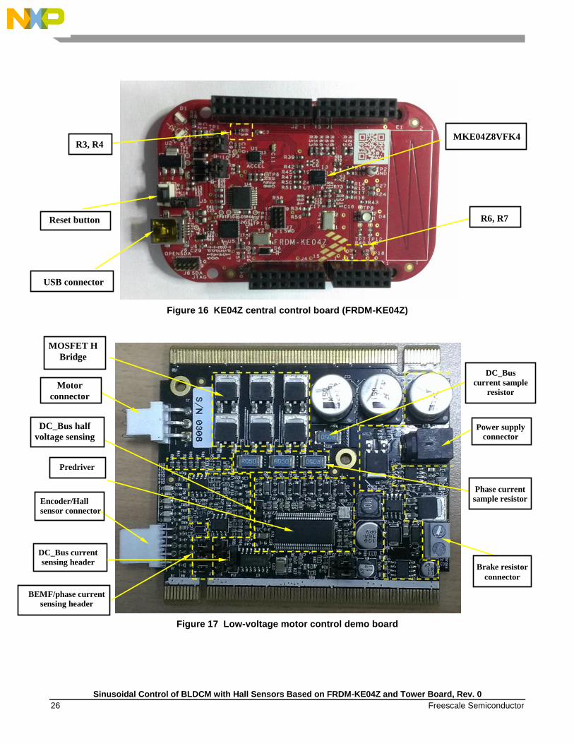
Figure 15 is KE04Z adapter board (FDRM2TWRMC-KE), Figure 16 is KE04Z central control board
(FRDM-KE04Z), and Figure 17 is low-voltage motor control board (TWR-MC-LV3PH).
Figure 15 TWR - MC - FRDMKE02Z adapter board
Primary
connector
Connector
Secondary
connector
Jumpers
Sinusoidal Control of BLDCM with Hall Sensors Based on FRDM-KE04Z and Tower Board, Rev. 0
26 Freescale Semiconductor
Figure 16 KE04Z central control board (FRDM-KE04Z)
Figure 17 Low-voltage motor control demo board
Brake resistor
connector
Encoder/Hall
sensor connector
Predriver
DC_Bus half
voltage sensing
DC_Bus
current sample
resistor
Power supply
connector
Motor
connector
Phase current
sample resistor
DC_Bus current
sensing header
MOSFET H
Bridge
MKE04Z8VFK4
USB connector
Reset button R6, R7
R3, R4
BEMF/phase current
sensing header

Sinusoidal Control of BLDCM with Hall Sensors Based on FRDM-KE04Z and Tower Board, Rev. 0
Freescale Semiconductor 27
6.2 Software setup
The software developing environment is IAR Embedded Workbench for ARM v6.6. USB/SCI driver
installation is required prior to the first usage of FreeMASTER. Driver installation is described in the MS
Word file “Installation USB/SCI Bridge manual”. After successfully installing the driver, select a virtual
COM port attached to the USB port, and then FreeMASTER is ready to use.
7 Debugging and conclusion
7.1 FreeMASTER communication
Figure 18 is a FreeMASTER GUI. Serial communication using the UART module is implemented for
remote control using FreeMASTER. The host computer is connected to the controller via a USB cable.
The computer USB port works as a virtual COM port. Signal conversion from USB form to UART form,
and vice versa, is done by the USB/UART bridge. In project -> Options -> Comm -> Communication,
select Direct RS232 as communication, and the baud rate is 9600 bps. In project->Options->MAP Files,
select the suffix for out file as Default symbol file and the “File format” as Binary ELF with DWARF1 or
DWARF2 dbg format.
Figure 18 FreeMASTER debug interface

Sinusoidal Control of BLDCM with Hall Sensors Based on FRDM-KE04Z and Tower Board, Rev. 0
28 Freescale Semiconductor
7.2 Phase current and phase voltage
Figure 19 shows the scope for a phase current waveform. The left figure shows the phase current using
6-step control and the right figure shows it using Sinusoidal control. Under the sinusoidal control, the
phase current has a sinusoidal waveform and there is less torque ripple.
Phase Current Using 6-Step Control Phase Current Using Sinusoidal Control
Figure 19 Phase current in two control modes
Figure 20 shows phase voltage in two modes. When using 6-step control with bipolar PWM, the phase
voltage is rectangular with constant dutycycle, as shown in the left figure. The right figure shows the
phase voltage when the motor is excited by sinusoidal voltage. This voltage is equivalent to the voltage
with saddle-shaped waveform shown in Figure 9 in the results that they generate in phase windings.
Phase Voltage Using 6-Step Control (Bipolar) Phase Voltage Using Sinusoidal Control
Figure 20 Phase voltage in two control modes
Sinusoidal Control of BLDCM with Hall Sensors Based on FRDM-KE04Z and Tower Board, Rev. 0
Freescale Semiconductor 29
8 References
The following references are available on freescale.com.
• KE04 Sub-Family Reference Manual (MKE04P24M48SF0RM)
• KE04 Series Data Sheet (MKE04P80M48SF0)
• TWRMCLV3PHUG: TWR-MC-LV3PH User’s Guide (TWRMCLV3PHUG)
• TWR-MC-LV3PH Schematics
• TWR-SER-SCH Schematics
Document Number: AN4869
Rev. 0
03/2014
How to Reach Us:
Home Page:
www.freescale.com
Web Support:
www.freescale.com/support
Information in this document is provided solely to enable system and software implementers to use Freescale products. There are no express or implied copyright licenses granted hereunder to design or fabricate any integrated circuits based on the information in this document.
Freescale reserves the right to make changes without further notice to any products herein. Freescale makes no warranty, representation, or guarantee regarding the suitability of its products for any particular purpose, nor does Freescale assume any liability arising out of the application or use of any product or circuit, and specifically disclaims any and all liability, including without limitation consequential or incidental damages. “Typical” parameters that may be provided in Freescale data sheets and/or specifications can and do vary in different applications, and actual performance may vary over time. All operating parameters, including “typicals,” must be validated for each customer application by customer’s technical experts. Freescale does not convey any license under its patent rights nor the rights of others. Freescale sells products pursuant to standard terms and conditions of sale, which can be found at the following address: freescale.com/SalesTermsandConditions.
Freescale, Kinetis, and the Freescale logo are trademarks of Freescale Semiconductor, Inc., Reg. U.S. Pat. & Tm. Off. All other product or service names are the property of their respective owners.
© 2014 Freescale Semiconductor, Inc.
Related Documents