Single Phase Induction Motor Adjustable Speed Control Using DSP and Microcontroller Course Project for ECE734 Fall Semester 2000 at UW-Madison Jianming Yao Abstract —In this project, the applications of VLSI in motor control is realized with two approaches: DSP and microcontroller. A single phase induction motor adjustable speed drive control is implemented with hardware setup and software program in C code. The main feature used in DSP and microcontroller is their peripherals to realize pulse width modulation. One chip and re-programmable ROM replaces the conventional complicated circuit solution. This brings low cost, small size and flexibility to change the control algorithm without changes in hardware. The experimental results are obtained and agree with the design objective. Introduction The applications of VLSI in motor control are getting more and more important and popular. In 1980s and 1990s, microprocessors, such as Intel’s 8080, 8031, 8098, 80196 and Motorola’s 68000, were mostly used in motor control. Recently, microcontroller are widely used in industry and the application of DSP and FPGA emerged in recent a couple of years. Both microcontrollers and DSPs are presently used in motor control; however, because of the real-time control algorithms that must be processed, the majority of these applications are driven by microcontrollers. This is partially due to engineers' comfort with microcontrollers and lack of familiarity with programming DSPs; however, DSPs are expected to surpass microcontrollers in the precision control of motors by 2003. Embedded motor control applications are expected to reach 7.3 billion units by 2001 (source: Motion Tech Trends). Motor control is a significant, but often ignored, segment of embedded applications. Motor control applications span everything from washing machines to fans, hand-held power tools, and automotive window lift and traction control systems. In most of these applications there is a move away from analog motor control to precision digital control of motors. Digital control of motors permits a much more

Welcome message from author
This document is posted to help you gain knowledge. Please leave a comment to let me know what you think about it! Share it to your friends and learn new things together.
Transcript
Single Phase Induction Motor Adjustable Speed Control
Using DSP and Microcontroller
Course Project for ECE734 Fall Semester 2000 at UW-Madison
Jianming Yao
Abstract—In this project, the applications of VLSI in motor control is realized with two
approaches: DSP and microcontroller. A single phase induction motor adjustable speed
drive control is implemented with hardware setup and software program in C code. The
main feature used in DSP and microcontroller is their peripherals to realize pulse width
modulation. One chip and re-programmable ROM replaces the conventional complicated
circuit solution. This brings low cost, small size and flexibility to change the control
algorithm without changes in hardware. The experimental results are obtained and agree
with the design objective.
Introduction
The applications of VLSI in motor control are getting more and more important and
popular. In 1980s and 1990s, microprocessors, such as Intel’s 8080, 8031, 8098, 80196
and Motorola’s 68000, were mostly used in motor control. Recently, microcontroller are
widely used in industry and the application of DSP and FPGA emerged in recent a couple
of years. Both microcontrollers and DSPs are presently used in motor control; however,
because of the real-time control algorithms that must be processed, the majority of these
applications are driven by microcontrollers. This is partially due to engineers' comfort
with microcontrollers and lack of familiarity with programming DSPs; however, DSPs
are expected to surpass microcontrollers in the precision control of motors by 2003.
Embedded motor control applications are expected to reach 7.3 billion units by 2001
(source: Motion Tech Trends). Motor control is a significant, but often ignored, segment
of embedded applications. Motor control applications span everything from washing
machines to fans, hand-held power tools, and automotive window lift and traction control
systems. In most of these applications there is a move away from analog motor control to
precision digital control of motors. Digital control of motors permits a much more
efficient operation of the motor, resulting in longer life, lower power dissipation, and a
lower overall system cost.
In motor control area, the applications of DSP and microcontroller is for control of DC
motor, brushless DC motor, brushless permanent magnet servo motor, AC induction
motor (IM), and switched reluctance motors. In this project, a single phase IM (SPIM) is
used for adjustable speed control because it is widely used in our daily life. To control
this SPIM, two hardware implementation will be done, one is to use micro-controller
PIC17C756 by Microchip and another is to use TMS320F240 by Texas Instrument.
SPIM Requirements
SPIM is used for most of the heating, ventilation, air-conditioning (HVAC) applications.
Normally, it has two windings: main and auxiliary while auxiliary winding has more
turns than main winding has. To do the adjustable speed control, two voltages must be
supplied to the main winding and auxiliary winding with variable frequencies and
variable amplitudes and they are subjected to the following constraints:
• Voltage ratio Vaux/Vmain is approximately equal to the effective turns ratio α,
Naux/Nmain (≈1.37 for the motor used for this project).
• Current ratio is Iaux/Imain=1/αVaux leads Vmain by 90º at rated frequency
• Constant V/Hz (voltage frequency ratio) for adjustable speed control
Previously, the phase shift of Vaux leading Vmain by 90º was done by putting a capacitor
in series with the auxiliary winding and then paralleling with main winding. The
adjustable speed is done by putting some inductor in series with the windings.
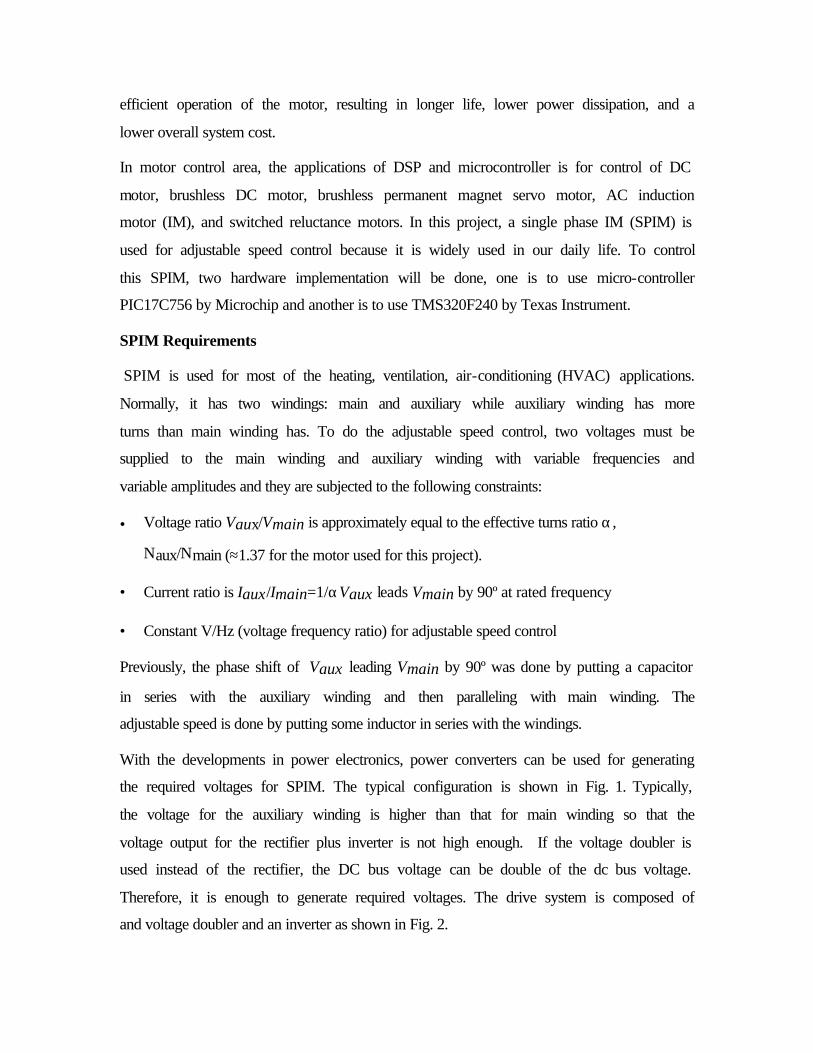
With the developments in power electronics, power converters can be used for generating
the required voltages for SPIM. The typical configuration is shown in Fig. 1. Typically,
the voltage for the auxiliary winding is higher than that for main winding so that the
voltage output for the rectifier plus inverter is not high enough. If the voltage doubler is
used instead of the rectifier, the DC bus voltage can be double of the dc bus voltage.
Therefore, it is enough to generate required voltages. The drive system is composed of
and voltage doubler and an inverter as shown in Fig. 2.
Front-endConverter
Inverter
ACinput
DC BusSingle-Phase
Motor
a
b
c
mainaux
Fig. 1 Configuration for SPIM adjustable speed drive
main
aux
ac
b
Fig. 2 Circuit topology for SPIM drive
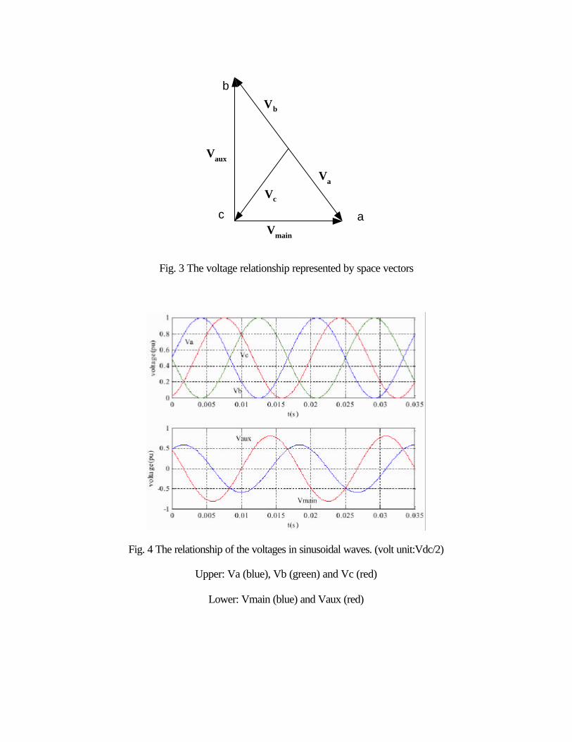
The voltages across the winding can be obtained by Vaux=Vb-Vc and Vmain=Va-Vc. If the
voltage space vectors are used, the relationship of these voltages can be shown in Fig. 3,
where the length of a vector stands for the magnitude and the angle of the vector is the
phase angle. In Fig. 3, the length of the vector is equal to half of the DC voltage. In order
to fully utilize the DC voltage, voltage Vb is just the inverse of Va, and Vc has a certain
angle from Va, such that the above mentioned constraints will the met. The voltages and
be express in (1) (2) and (3) and can be computed with the results in sinusoidal
waveforms as shown in Fig. 4.
)sin(21
tVV dca ω= (1)
−= −
aux
maindcc V
VtVV 1tan2sin
21
ω (2)
)sin(21
tVV dcb ω−= (3)
b
ac
Vb
Va
Vc
Vaux
Vmain
Fig. 3 The voltage relationship represented by space vectors
Fig. 4 The relationship of the voltages in sinusoidal waves. (volt unit:Vdc/2)
Upper: Va (blue), Vb (green) and Vc (red)
Lower: Vmain (blue) and Vaux (red)
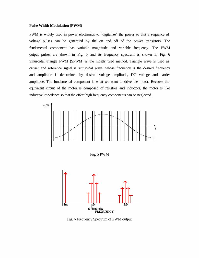
Pulse Width Modulation (PWM)
PWM is widely used in power electronics to “digitalize” the power so that a sequence of
voltage pulses can be generated by the on and off of the power transistors. The
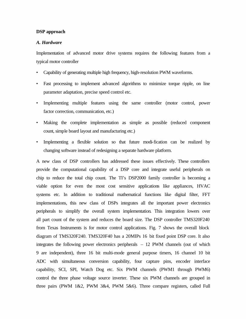
fundamental component has variable magnitude and variable frequency. The PWM
output pulses are shown in Fig. 5 and its frequency spectrum is shown in Fig. 6
Sinusoidal triangle PWM (SPWM) is the mostly used method. Triangle wave is used as
carrier and reference signal is sinusoidal wave, whose frequency is the desired frequency
and amplitude is determined by desired voltage amplitude, DC voltage and carrier
amplitude. The fundamental component is what we want to drive the motor. Because the
equivalent circuit of the motor is composed of resistors and inductors, the motor is like
inductive impedance so that the effect high frequency components can be neglected.
Fig. 5 PWM
Fig. 6 Frequency Spectrum of PWM output
DSP approach
A. Hardware
Implementation of advanced motor drive systems requires the following features from a
typical motor controller
• Capability of generating multiple high frequency, high-resolution PWM waveforms.
• Fast processing to implement advanced algorithms to minimize torque ripple, on line
parameter adaptation, precise speed control etc.
• Implementing multiple features using the same controller (motor control, power
factor correction, communication, etc.)
• Making the complete implementation as simple as possible (reduced component
count, simple board layout and manufacturing etc.)
• Implementing a flexible solution so that future modi-fication can be realized by
changing software instead of redesigning a separate hardware platform.
A new class of DSP controllers has addressed these issues effectively. These controllers
provide the computational capability of a DSP core and integrate useful peripherals on
chip to reduce the total chip count. The TI’s DSP2000 family controller is becoming a
viable option for even the most cost sensitive applications like appliances, HVAC
systems etc. In addition to traditional mathematical functions like digital filter, FFT
implementations, this new class of DSPs integrates all the important power electronics
peripherals to simplify the overall system implementation. This integration lowers over
all part count of the system and reduces the board size. The DSP controller TMS320F240
from Texas Instruments is for motor control applications. Fig. 7 shows the overall block
diagram of TMS320F240. TMS320F40 has a 20MIPs 16 bit fixed point DSP core. It also
integrates the following power electronics peripherals – 12 PWM channels (out of which
9 are independent), three 16 bit multi-mode general purpose timers, 16 channel 10 bit
ADC with simultaneous conversion capability, four capture pins, encoder interface
capability, SCI, SPI, Watch Dog etc. Six PWM channels (PWM1 through PWM6)
control the three phase voltage source inverter. These six PWM channels are grouped in
three pairs (PWM 1&2, PWM 3&4, PWM 5&6). Three compare registers, called Full
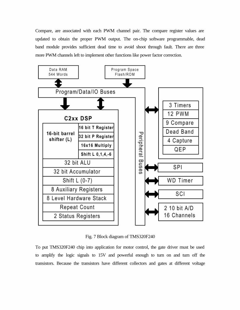
Compare, are associated with each PWM channel pair. The compare register values are
updated to obtain the proper PWM output. The on-chip software programmable, dead
band module provides sufficient dead time to avoid shoot through fault. There are three
more PWM channels left to implement other functions like power factor correction.
Fig. 7 Block diagram of TMS320F240
To put TMS320F240 chip into application for motor control, the gate driver must be used
to amplify the logic signals to 15V and powerful enough to turn on and turn off the
transistors. Because the transistors have different collectors and gates at different voltage
levels as shown in Fig. 2, the gate drivers (amplifiers) cannot use a common ground.
Therefore, the dc power supply for those gate drivers should be isolated.
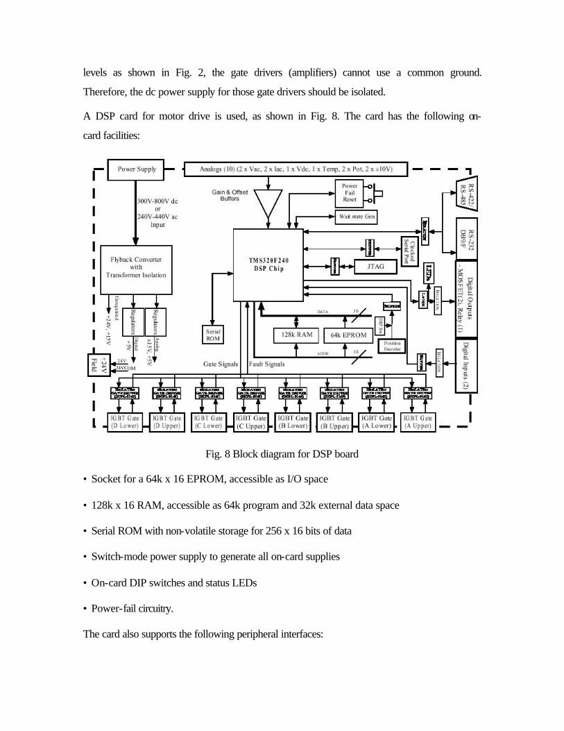
A DSP card for motor drive is used, as shown in Fig. 8. The card has the following on-
card facilities:
Fig. 8 Block diagram for DSP board
• Socket for a 64k x 16 EPROM, accessible as I/O space
• 128k x 16 RAM, accessible as 64k program and 32k external data space
• Serial ROM with non-volatile storage for 256 x 16 bits of data
• Switch-mode power supply to generate all on-card supplies
• On-card DIP switches and status LEDs
• Power-fail circuitry.
The card also supports the following peripheral interfaces:
• RS-232/RS-422/RS-485 serial interface
• High speed clocked serial peripheral interface
• 2 off isolated digital inputs
• 2 off MOSFET switch isolated outputs
• 1 off relay output, c/o contact
• 2 off AC current inputs
• 2 off differential AC voltage inputs,
• 1 off differential DC voltage input
• 1 off flexible temperature sensor input
• 2 off potentiometer analog inputs
• 2 off general purpose analog inputs (± 10V default)
• 8 off complementary isolated gate driver PWM outputs, with common fault interrupt
• +24V isolated field supply
• JTAG port for software development.
• Quadrature Position Encoder input with Index
Digital I/O
The DSP240 card supports 13 bits of digital I/O, consisting of 8 bits for local I/O and 5
bits interfacing to external isolated circuitry. The local I/O consists of 4 bits driving
LED’s mounted on-card (LED3, LED4, LED5, LED6) and 4 bits of DIP switch inputs
(S2). The isolated I/O consists of 2 off isolated digital inputs, 1 off relay output
(changeover contact) and 2 off isolated MOSFET outputs. The isolated digital inputs can
be driven using either the on-card generated +24V field supply, or individually isolated to
be driven from an off-card supply. This is achieved by removing a grounding link (LK15,
LK18) located next to each input connector. The controller card is supplied with these
links installed, to connect the common of the isolated digital outputs to the negative rail
of the +24V field supply. A LED indicator is provided on the isolated side of each input
as a visual indication of the state of the input. The 1 off relay output has DPST
changeover contacts capable of driving 10A 240Vac. A LED indicator is provided on the
coil side of the output as a visual indication of the state of the output. The 2 off MOSFET
outputs can be link selected (LK13, LK14) to be powered from either the on-card
generated +24V field supply or from an off-card source. Both MOSFETs must be driven
from the same supply option. The controller card is supplied with these links present, to
connect the positive and negative rail of the +24V field supply to the MOSFET outputs.
Both MOSFET outputs have LED indicators on the isolated side to provide a visual
indication of the state of the output.
Analog Inputs
The DSP chip has two off 10-bit A/D converters with individual built-in Sample and
Hold circuits. Eight analog inputs are provided for each ADC through 8 to 1 analog
multiplexers. This enables two input channels, one on each ADC, to be simultaneously
sampled and converted. The maximum total conversion time for each ADC unit is 6.6ms.
The DSP A/D converters accept input voltages in the range of 0-5V. The analog inputs
are interfaced as 2 off AC currents, 2 off AC voltages, 1 off DC voltage, 1 off
temperature sensor, 2 off potentiometers and 2 off ±10V general purpose inputs. The AC
current inputs require the placement of burden resistors (R17, R18) on the card, selected
so that the full-scale voltage developed across each resistor ranges between ±550mV.
Standoffs are provided on-card for ease of mounting these resistors. If required,
capacitors (C9, C10) can be added in parallel with the sense resistors to reduce unwanted
high frequency noise. Separate grounds are provided on each current connector so that
each current input can be connected using individual twisted pair wires. A common
overcurrent detection is provided for both AC current inputs, with the trip level
determined by resistor R112 (mounted on standoffs). The AC voltage inputs have a
default input voltage range of ±750V peak. This can be reduced by mounting gain
resistors (R23, R25, R27) onto standoffs on the PCB. The two AC voltage inputs are
differential high impedance circuits, allowing the line-line AC voltages to be measured
from a three phase system. One input voltage (Vab) supports a zero-crossing detect
circuit, which drives a DSP capture input. The DC voltage input has a default input
voltage range of 928V. This can be reduced by mounting gain resistors (R41, R44) onto
standoffs on the PCB. The DC voltage input is a differential high impedance circuit,
allowing the DC voltage to be measured between two floating rails. A DC overvoltage
detection circuit is provided for this input, with the trip level determined by resistor R111
(mounted on standoffs). The temperature sense input supports temperature measurement
using a RTD or LM35DZ temperature sensing device. A 1.0mA current source can be
linked (LK5) to develop the sense voltage across the RTD. The offset and gain of the
temperature sense system can be varied by changing resistors R64, R67. The
potentiometer inputs can be link selected (LK3, LK4) to use either on-card trimpots, or an
external potentiometer located off-card. A 5V reference voltage is available at the
potentiometer connector to energize an external potentiometer. The two general purpose
analog inputs accept a ±10V input. Each input has a 1 megohm resistor connected to
ground to stabilize the DC level.
Gate Drive Interface
The TMS320F240 DSP supports 8 PWM channel outputs, made up of 3 complementary
pairs (6 outputs) with programmable deadbands and 2 independent outputs generated by
simple compare functions. The DSP240 board uses the 8 PWM channel outputs to
generate the 8 gate signals, and converts these outputs to 8 isolated gate driver outputs
through HCPL-316J gate driver chips. Two of the gate drive outputs require dead band
compensation to be software-calculated. Isolated supplies are generated on-card for each
gate drive circuit. Gate fault signals from the eight HCPL-316J’s are linked together and
connected to the PDPINT* interrupt. This provides a hardware interrupt to the DSP
immediately on detection of a fault, which disables the PWM signals within 200
nanoseconds using internal hardware logic within the DSP.
Communications
The DSP240 controller board supports four communication protocols: RS-232, RS-422,
multi-drop RS-485 and a high-speed synchronous serial peripheral interface. The DSP
incorporates asingle UART, which is used for RS-232/422/485 communication. A link
(LK11) is provided to select between these three communication protocols. These signals
are isolated through optocouplers from the main PCB. The high-speed synchronous serial
peripheral interface can be used to communicate to other computer systems. The interface
can support either master or slave protocol, selected by software.
On-card memory
The DSP240 controller board supports 64k x 16bit each of on-card Program RAM and
Data RAM. This memory is interleaved with the DSP internal memory using the on-chip
memory management hardware. The PCB also supports 64k x 16bit EPROM, mapped to
the DSP I/O address space. Programs cannot be executed directly from the EPROM
memory, but rather the EPROM can be used to store programs, which can be block
moved to Program RAM for execution as required. The DSP240 controller board also
supports 256 x 16bits of non-volatile serial ROM, which is programmed from the DSP
using I/O signals on Port B.
Power Supply
The standard DSP240 controller board has an on-card switch mode power supply that
accepts an input voltage in the range of 240V – 440V AC or 300V – 800V DC. The
SMPS generates all necessary on-card supplies as well as an isolated current-limited
+24V field supply for off-card use. The DSP240 (LV) controller board has an on-card
switch mode power supply that accepts an input voltage in the range of 90V – 260V AC
or 130 – 370V DC.
Programming
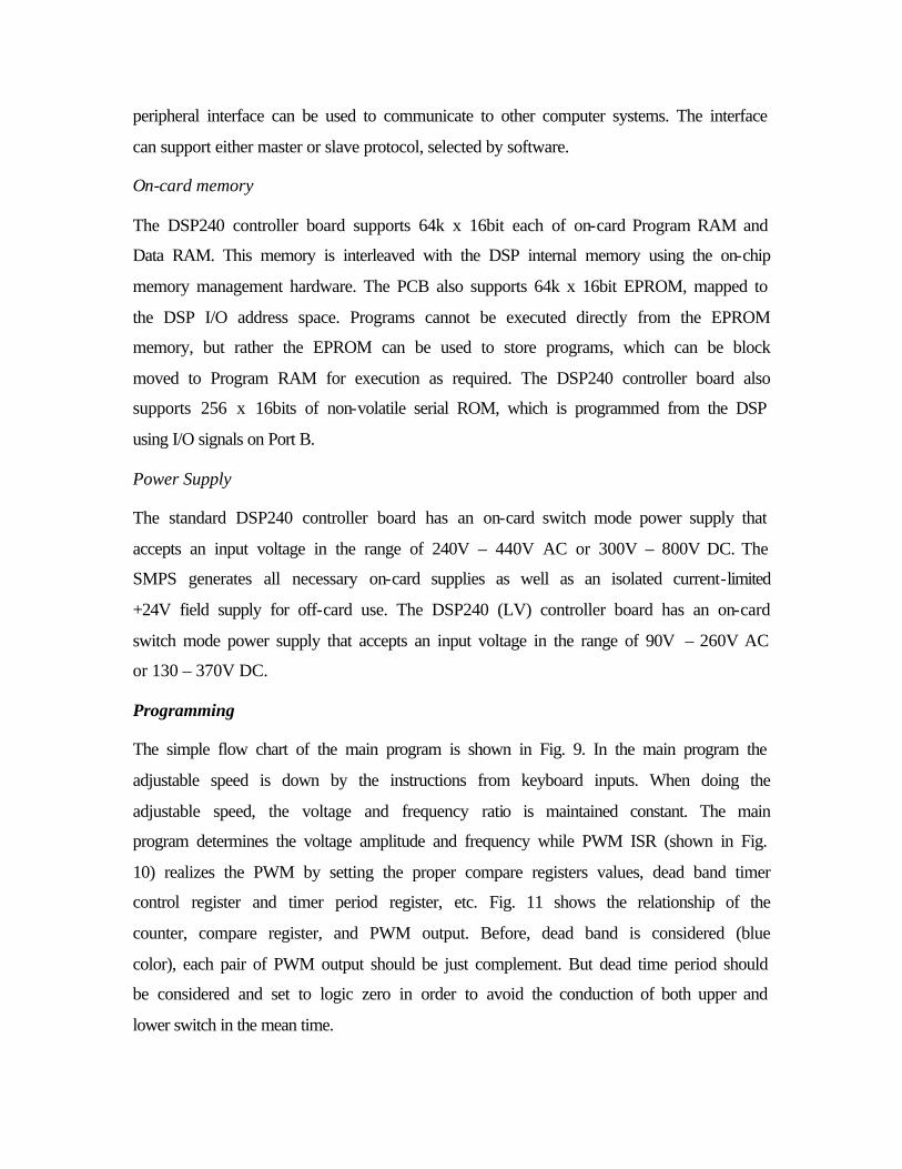
The simple flow chart of the main program is shown in Fig. 9. In the main program the
adjustable speed is down by the instructions from keyboard inputs. When doing the
adjustable speed, the voltage and frequency ratio is maintained constant. The main
program determines the voltage amplitude and frequency while PWM ISR (shown in Fig.
10) realizes the PWM by setting the proper compare registers values, dead band timer
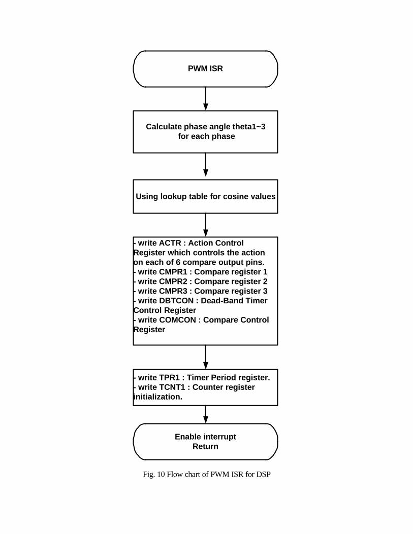
control register and timer period register, etc. Fig. 11 shows the relationship of the
counter, compare register, and PWM output. Before, dead band is considered (blue
color), each pair of PWM output should be just complement. But dead time period should
be considered and set to logic zero in order to avoid the conduction of both upper and
lower switch in the mean time.
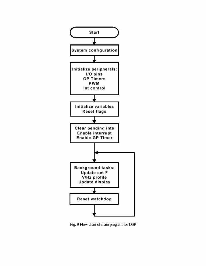
Fig. 9 Flow chart of main program for DSP
PWM ISR
Calculate phase angle theta1~3 for each phase
Using lookup table for cosine values
- write ACTR : Action ControlRegister which controls the actionon each of 6 compare output pins.- write CMPR1 : Compare register 1- write CMPR2 : Compare register 2- write CMPR3 : Compare register 3- write DBTCON : Dead-Band TimerControl Register- write COMCON : Compare ControlRegister
- write TPR1 : Timer Period register.- write TCNT1 : Counter registerinitialization.
Enable interruptReturn
Fig. 10 Flow chart of PWM ISR for DSP
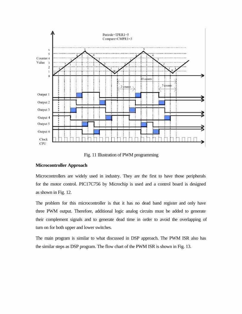
Fig. 11 Illustration of PWM programming
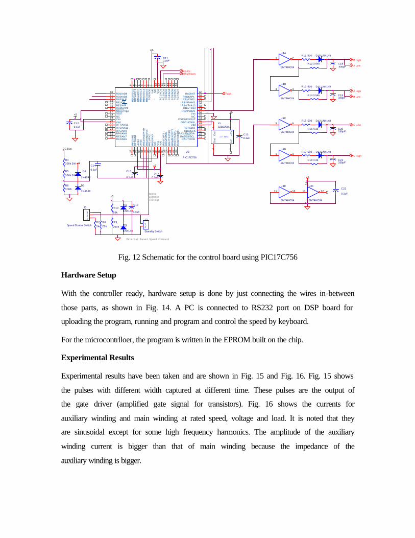
Microcontroller Approach
Microcontrollers are widely used in industry. They are the first to have those peripherals
for the motor control. PIC17C756 by Microchip is used and a control board is designed
as shown in Fig. 12.
The problem for this microcontroller is that it has no dead band register and only have
three PWM output. Therefore, additional logic analog circuits must be added to generate
their complement signals and to generate dead time in order to avoid the overlapping of
turn on for both upper and lower switches.
The main program is similar to what discussed in DSP approach. The PWM ISR also has
the similar steps as DSP program. The flow chart of the PWM ISR is shown in Fig. 13.
C15
0.1uF
A Low
U4C
SN74HC04
5 6
+5
R10
10k
+5
U4F
SN74HC04
13 12
14
7
R7
5k
+5
C160.1uF
Fault
R12 3.54k
J2
Standby Switch
12
C17
0.1uF
R63.92k
D13 1N4148
R13 500
D9
1N4148
+5
R5
300k 2W
C130.1uF
D7
1N4148
ShutDown
R4300k 2W
C110.1uF
U4E
SN74HC04
11 10
R18 4.3k
R16 4.3k
R17 500
D10 1N4148
U4B
SN74HC04
3 4
R9
200k
U3
PIC17C756
123456789
1011121314151617181920212223242526
27
28
29
30
31
32
33
34
35
36
37
38
39
40
41
42
43
4445464748495051525354555657585960
61
62
63
64
65
66
67
68
NC
Vd
dR
C0
/AD
0R
D7
/AD
15
RD
6/A
D1
4R
D5
/AD
13
RD
4/A
D1
2R
D3
/AD
11
RD
2/A
D1
0
RD1/AD9RD0/AD8RE0/ALERE1/OERE2/WRRE3/CAP4MCLR/VppTESTNCVssVddRF7/AN11RF6/AN10RF5/AN9RF4/AN8RF3/AN7RF2/AN6
RF
1/A
N5
RF
0/A
N4
AV
ddA
Vss
RG
3/A
N0/
Vre
f+R
G2/
AN
0/V
ref-
RG
1/A
N2
RG
0/A
N3
NC
Vss
Vd
dR
G4/
CA
P3
RG
5/P
WM
3R
G7/
TX
2/C
K2
RG
6/R
X2
/DT
2R
A5/
TX
1/C
K1
RA
4/R
X1/
DT
1
RA1/TOCKIRA2/SS/SCL
RA3/SDI/SDARB6/SCKRB7/SDO
VddOSC1/ClkIN
OSC2/ClkOUTNCVss
RB2/PWM1RB5/Tclk3
RB4/Tclk12RB3/PWM2RB1/CAP2RB0/CAP1
RA0/INT
RC
7/A
D7
RC
6/A
D6
RC
5/A
D5
RC
4/A
D4
RC
3/A
D3
RC
2/A
D2
RC
1/A
D1
Vss
B Low
C High
20 MHz
X152B3200
145 8
NC
Gn
dO
ut
+5
V
+5
R8
20k
C19330pF
D6
1N4148
C120.1uF
+5
C Low
R14 3.54k
C18330pF
SpeedCommandVoltage
External Based Speed Command
Flt-Clr
U4A
SN74HC04
1 2
DC Bus
J3
Speed Control Switch
123
R11 500
U4D
SN74HC04
9 8
C22
0.1uF
D11 1N4148
R15 500
C21330pF
D8
1N4148
+5
D12 1N4148
B High
A High
C14
0.1uF
C20330pF
Fig. 12 Schematic for the control board using PIC17C756
Hardware Setup
With the controller ready, hardware setup is done by just connecting the wires in-between
those parts, as shown in Fig. 14. A PC is connected to RS232 port on DSP board for
uploading the program, running and program and control the speed by keyboard.
For the microcontrlloer, the program is written in the EPROM built on the chip.
Experimental Results
Experimental results have been taken and are shown in Fig. 15 and Fig. 16. Fig. 15 shows
the pulses with different width captured at different time. These pulses are the output of
the gate driver (amplified gate signal for transistors). Fig. 16 shows the currents for
auxiliary winding and main winding at rated speed, voltage and load. It is noted that they
are sinusoidal except for some high frequency harmonics. The amplitude of the auxiliary
winding current is bigger than that of main winding because the impedance of the
auxiliary winding is bigger.
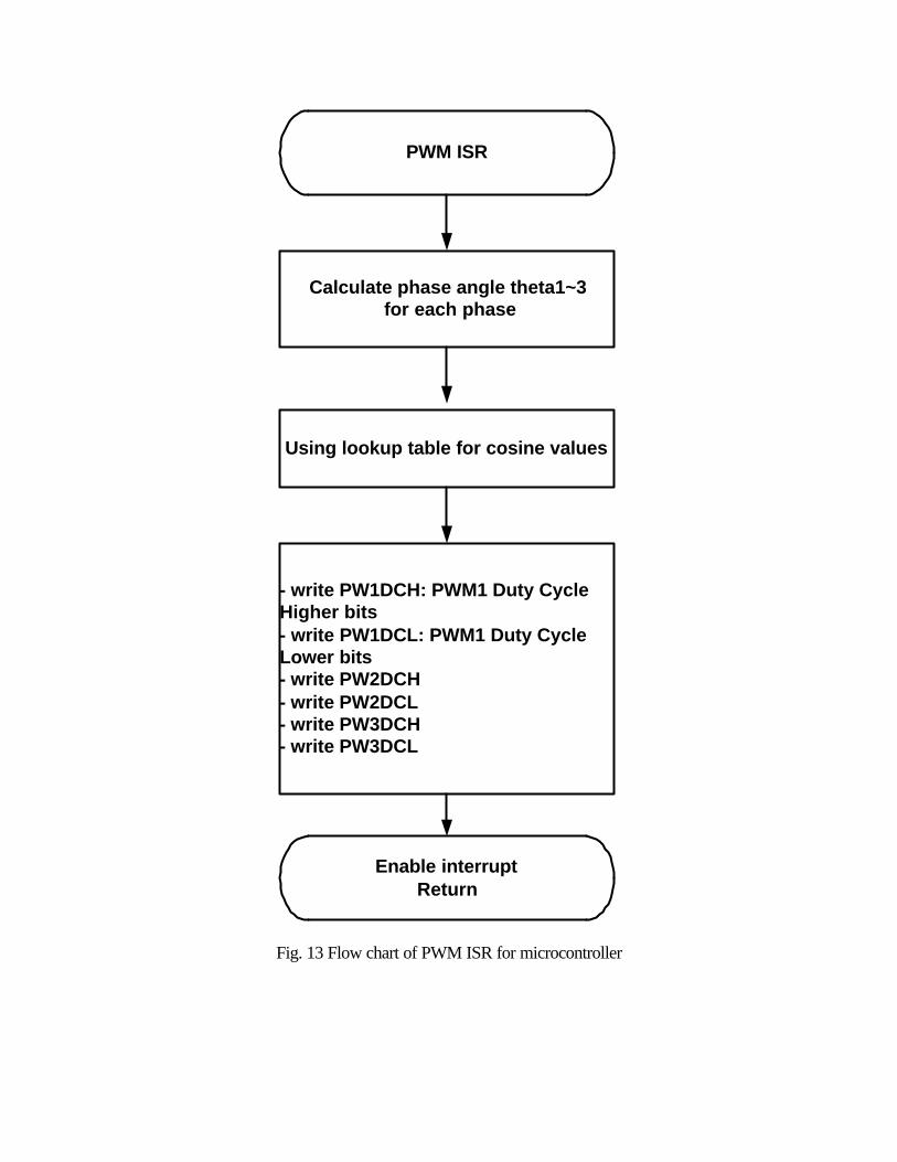
PWM ISR
Calculate phase angle theta1~3 for each phase
Using lookup table for cosine values
- write PW1DCH: PWM1 Duty CycleHigher bits- write PW1DCL: PWM1 Duty CycleLower bits- write PW2DCH- write PW2DCL- write PW3DCH- write PW3DCL
Enable interruptReturn
Fig. 13 Flow chart of PWM ISR for microcontroller
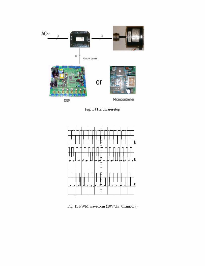
Fig. 14 Hardwaresetup
Fig. 15 PWM waveform (10V/div, 0.1ms/div)
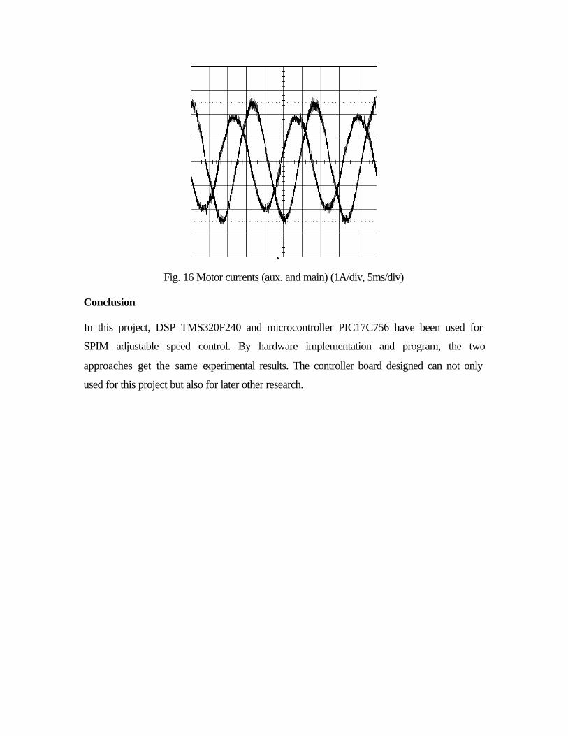
Fig. 16 Motor currents (aux. and main) (1A/div, 5ms/div)
Conclusion
In this project, DSP TMS320F240 and microcontroller PIC17C756 have been used for
SPIM adjustable speed control. By hardware implementation and program, the two
approaches get the same experimental results. The controller board designed can not only
used for this project but also for later other research.
Appendices for ECE734 Project by Jianming Yao Fall 2000
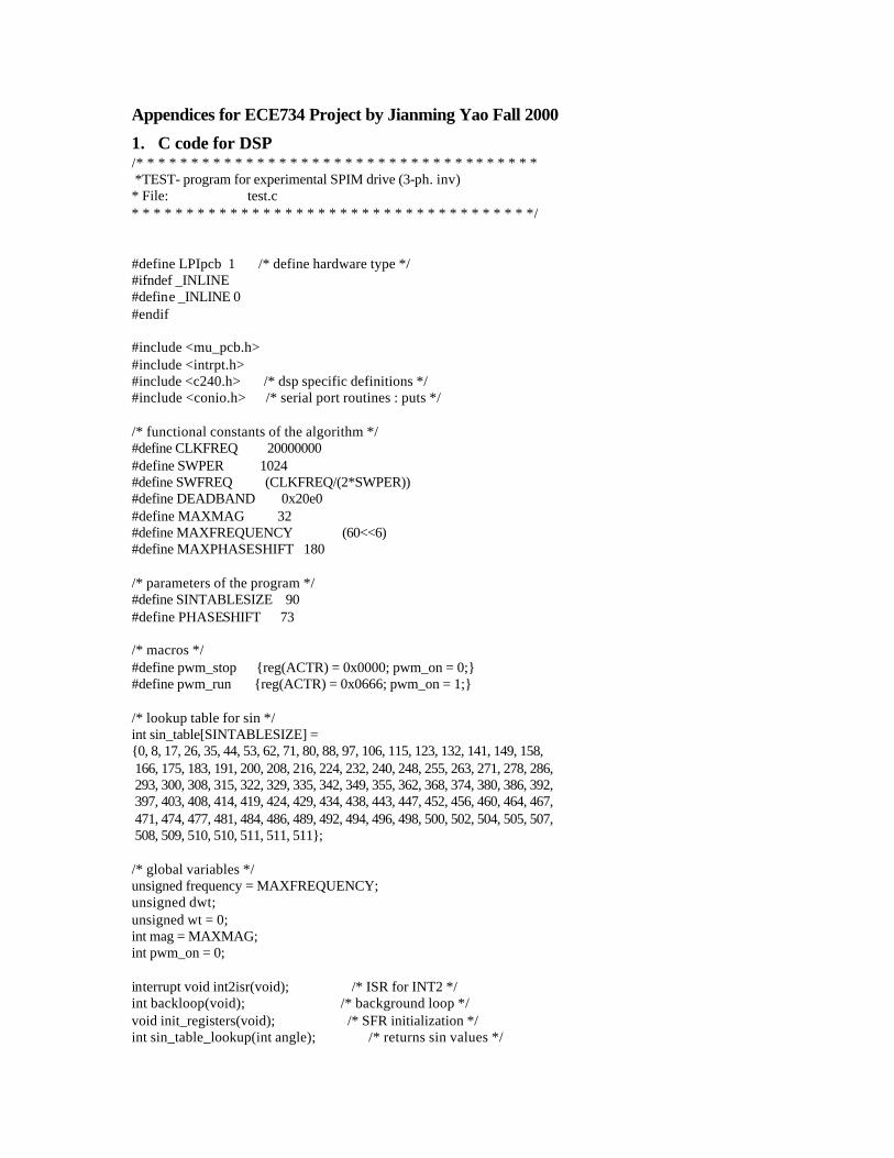
1. C code for DSP /* * * * * * * * * * * * * * * * * * * * * * * * * * * * * * * * * * * * * *TEST- program for experimental SPIM drive (3-ph. inv) * File: test.c * * * * * * * * * * * * * * * * * * * * * * * * * * * * * * * * * * * * */ #define LPIpcb 1 /* define hardware type */ #ifndef _INLINE #define _INLINE 0 #endif #include <mu_pcb.h> #include <intrpt.h> #include <c240.h> /* dsp specific definitions */ #include <conio.h> /* serial port routines : puts */ /* functional constants of the algorithm */ #define CLKFREQ 20000000 #define SWPER 1024 #define SWFREQ (CLKFREQ/(2*SWPER)) #define DEADBAND 0x20e0 #define MAXMAG 32 #define MAXFREQUENCY (60<<6) #define MAXPHASESHIFT 180 /* parameters of the program */ #define SINTABLESIZE 90 #define PHASESHIFT 73 /* macros */ #define pwm_stop {reg(ACTR) = 0x0000; pwm_on = 0;} #define pwm_run {reg(ACTR) = 0x0666; pwm_on = 1;} /* lookup table for sin */ int sin_table[SINTABLESIZE] = {0, 8, 17, 26, 35, 44, 53, 62, 71, 80, 88, 97, 106, 115, 123, 132, 141, 149, 158, 166, 175, 183, 191, 200, 208, 216, 224, 232, 240, 248, 255, 263, 271, 278, 286, 293, 300, 308, 315, 322, 329, 335, 342, 349, 355, 362, 368, 374, 380, 386, 392, 397, 403, 408, 414, 419, 424, 429, 434, 438, 443, 447, 452, 456, 460, 464, 467, 471, 474, 477, 481, 484, 486, 489, 492, 494, 496, 498, 500, 502, 504, 505, 507, 508, 509, 510, 510, 511, 511, 511}; /* global variables */ unsigned frequency = MAXFREQUENCY; unsigned dwt; unsigned wt = 0; int mag = MAXMAG; int pwm_on = 0; interrupt void int2isr(void); /* ISR for INT2 */ int backloop(void); /* background loop */ void init_registers(void); /* SFR initialization */ int sin_table_lookup(int angle); /* returns sin values */
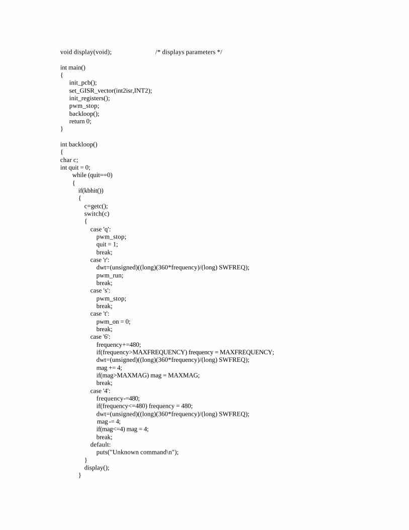
void display(void); /* displays parameters */ int main() { init_pcb(); set_GISR_vector(int2isr,INT2); init_registers(); pwm_stop; backloop(); return 0; } int backloop() { char c; int quit = 0; while (quit==0) { if(kbhit()) { c=getc(); switch(c) { case 'q': pwm_stop; quit = 1; break; case 'r': dwt=(unsigned)((long)(360*frequency)/(long) SWFREQ); pwm_run; break; case 's': pwm_stop; break; case 't': pwm_on = 0; break; case '6': frequency+=480; if(frequency>MAXFREQUENCY) frequency = MAXFREQUENCY; dwt=(unsigned)((long)(360*frequency)/(long) SWFREQ); mag += 4; if(mag>MAXMAG) mag = MAXMAG; break; case '4': frequency-=480; if(frequency<=480) frequency = 480; dwt=(unsigned)((long)(360*frequency)/(long) SWFREQ); mag -= 4; if(mag<=4) mag = 4; break; default: puts("Unknown command\n"); } display(); }
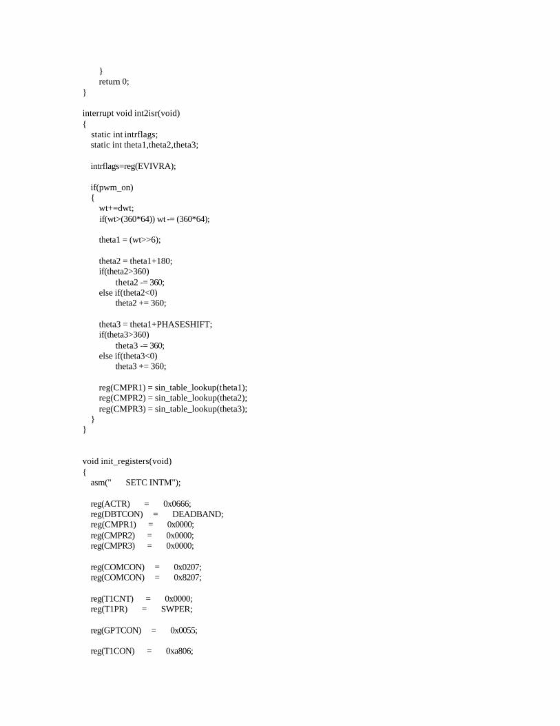
} return 0; } interrupt void int2isr(void) { static int intrflags; static int theta1,theta2,theta3; intrflags=reg(EVIVRA); if(pwm_on) { wt+=dwt; if(wt>(360*64)) wt -= (360*64); theta1 = (wt>>6); theta2 = theta1+180; if(theta2>360) theta2 -= 360; else if(theta2<0) theta2 += 360; theta3 = theta1+PHASESHIFT; if(theta3>360) theta3 -= 360; else if(theta3<0) theta3 += 360; reg(CMPR1) = sin_table_lookup(theta1); reg(CMPR2) = sin_table_lookup(theta2); reg(CMPR3) = sin_table_lookup(theta3); } } void init_registers(void) { asm(" SETC INTM"); reg(ACTR) = 0x0666; reg(DBTCON) = DEADBAND; reg(CMPR1) = 0x0000; reg(CMPR2) = 0x0000; reg(CMPR3) = 0x0000; reg(COMCON) = 0x0207; reg(COMCON) = 0x8207; reg(T1CNT) = 0x0000; reg(T1PR) = SWPER; reg(GPTCON) = 0x0055; reg(T1CON) = 0xa806;

reg(EVIFRA) = 0xffff; reg(EVIMRA) = 0x0200; reg(IMR) = 0x000a; reg(T1CON) = 0xa846; asm(" CLRC INTM"); } int sin_table_lookup(int angle) { static int count; if(angle<90) count = ((mag*sin_table[angle])>>5)+SWPER/2; else if(angle<180) count = ((mag*sin_table[180-angle-1])>>5)+SWPER/2; else if(angle<270) count = SWPER/2-((mag*sin_table[angle-180])>>5); else count = SWPER/2-((mag*sin_table[360-angle-1])>>5); return count; } void display(void) { if (pwm_on) puts("RUN "); else puts("STOP "); puts(" Freq: "); putf(frequency,64,1); puts(" Magnitude: "); putf(mag,32,2); puts(" \r"); } 2. C code for microcontroller /*****************************************************************/
/* */
/* Single -Phase Induction Motor Drive Controller Code */
/* */
/* This program is for a PIC 17C756 microcomputer based drive */
/* which uses a 3-phase PWM inverter to drive a single -phase, */
/* capacitor-run induction motor directly. The two PWM channels */
/* PWM1 and PWM3 generate appropriate voltage waveforms for three*/
/* motor terminals: Main, Auxiliary and Common, so that the motor*/
/* will run at the commanded speed. */
/* */
/* Command Input: ADC Channel AN2, @ CPU pin 0-5V=0-full speed */
/* V_AN2 < 1V == Off */
/* 1V < V_AN2 < 3V == 20 Hz */
/* 3V < V_AN2 < 4V == 40 Hz */
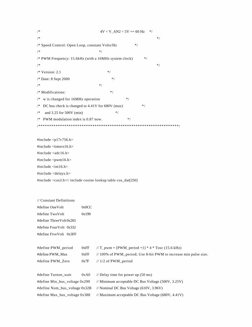
/* 4V < V_AN2 < 5V == 60 Hz */
/* */
/* Speed Control: Open Loop, constant Volts/Hz */
/* */
/* PWM Frequency: 15.6kHz (with a 16MHz system clock) */
/* */
/* Version: 2.1 */
/* Date: 8 Sept 2000 */
/* */
/* Modifications: */
/* w is changed for 16MHz operation */
/* DC bus check is changed to 4.41V for 680V (max) */
/* and 3.25 for 500V (min) */
/* PWM modulation index is 0.87 now. */
/*****************************************************************/
#include <p17c756.h>
#include <timers16.h>
#include <adc16.h>
#include <pwm16.h>
#include <int16.h>
#include <delays.h>
#include <cos3.h>// include cosine lookup table cos_dat[250]
// Constant Definitions
#define OneVolt 0x0CC
#define TwoVolt 0x199
#define ThreeVolt0x265
#define FourVolt 0x332
#define FiveVolt 0x3FF
#define PWM_period 0xFF // T_pwm = [PWM_period +1] * 4 * Tosc (15.6 kHz)
#define PWM_Max 0xFF // 100% of PWM_period; Use 8-bit PWM to increase min pulse size.
#define PWM_Zero 0x7F // 1/2 of PWM_period
#define Turnon_wait 0xA0 // Delay time for power up (50 ms)
#define Min_bus_voltage 0x299 // Minimum acceptable DC Bus Voltage (500V, 3.25V)
#define Nom_bus_voltage 0x32B // Nominal DC Bus Voltage (610V, 3.96V)
#define Max_bus_voltage 0x388 // Maximum acceptable DC Bus Voltage (680V, 4.41V)
#define OffValue 0x0CE // Maximum A/D input value for Drive to remain OFF. (~1V)
#define LowSpeed0x26A // Maximum A/D input value for Drive to be in Low Speed Mode. (3V)
#define MedSpeed0x338 // Maximum A/D input value for Drive to be in Medium Speed Mode. (4V)
#define Theta3 0x120 // Angle offset based on alpha (Assumes Speed Independence)
// Alpha=1.39; Theta=108.57 deg; Angle360=996 & then tweaked.
#define LowAmp 0x002 // Low Speed Output Voltage Amplitude
#define LowOmega0x006 // Low Speed Frequency w/ 250pt Cos
#define MedAmp 0x003 // Medium Speed Output Voltage Amplitude
#define MedOmega0x009 // Medium Speed Frequency w/250 pt Cos
#define HighAmp 0x004 // High Speed Output Voltage Amplitude
#define HighOmega 0x00C // High Speed Frequency w/250 pt Cos
// Function prototypes
void __STARTUP(void); // Device Reset Startup code
void energize_drive(void); // Drive Power stage turn -on
void depower_drive(void); // Drive Power stage turn -off
void error(void); // Drive error handling code
void isr(void); // Drive Duty-cycle interrupt service routine
void cos(void); // Cosine lookup function
void SetupPWM(void); // PWM register setup and configureation
void configure_interrupts(void); // Sets up the two interrupt routine vectors
void gate_fault(void); // Gate fault current interrupt service routine
// Context register save
#pragma udata intSave = 0xF6
unsigned char save_TBLPTRL_; // Used for Comparisons (< >) and table reads (cos[])!
unsigned char save_TBLPTRH_; // The extra _ is to assure a unique location...
unsigned char save_PRODL; // Used for multiplications
unsigned char save_PRODH;
unsigned char save_FSR0; // Used for arrays??
unsigned char save_FSR1; // Used to make 16-bit Wreg!
#pragma udata anywhere
// 'True' Global Variables
unsigned char Code; // Error condition code word
char Busy; // V/Hz computation in progress
char Off; // Drive is in command shutdown mode
unsigned char Amp; // Inverter Output Amplitude
unsigned char Amplitude; // New Command Output Amplitude
unsigned char Old_amp;// Previous Command Output Amplitude
unsigned char Omega; // New Command Frequency
unsigned char Old_omega; // Previous Command Frequency
unsigned char ItripCnt; // Number of current trip faults
// ISR Global Variables
unsigned int wt; // 'omega*time'
int Theta; // cos/mcos angle
unsigned char W ; // Inverter output frequency
unsigned int pos; // amplitude*cos
unsigned char dc1; // PWM channel 1 duty cycle
unsigned char dc3; // PWM channel 3 duty cycle
// cos/mcos Global Variables
unsigned char sgn; // cos/mcos sign bit
unsigned char cout; // cos/mcos result value
unsigned char val; // cos/mcos index pointer 'local'
// main Global Variables
unsigned int Vcommand; // Commanded speed voltage
unsigned int Vbus; // DC Bus Voltage
// Functions and Procedures
void __STARTUP(void)
// This function assures that the external registers are
// all in a proper off state.
{
DDRC=0X00; // Set Port C to be output
PORTC=0b00000100; // Clear possible gate drive fault
PORTC=0b00000100;
PORTC=0b00000110;
/* |||||||+---- not used
||||||+----- Fault -Clr*
|||||+------ Shut down active -> Gate drive off
||||+------- not used
|||+-------- not used
+++--------- Not used */
}
void gate_fault(void)
// This procedure handles the error condition of fault current
// in the gate drive... Now, just pull plug and halt, unless it
// was due to our turning-off the gate drive chip in which case
// we reset the gate-drive chip and move along!
{
CPUSTAbits.GLINTD = 1; // Disable global interrupts
if (Off==0)
{ // Legitmate Error Condition
ItripCnt++;
if (ItripCnt > 1) // Check to see if its just a passing
{ // condition (and we'll ignore it) or
error(); // and die!
}
}
// Fault signal just letting us know that
// the gate drive shut down, so we need to
// reset it.
// "nothing to see here, move along..."
PORTCbits.RC1=0; // Clear Gate Drive Chip's Fault
CPUSTAbits.GLINTD = 0; // Enable global interrupts
}
void configure_interrupts(void)
// This procedure sets the interrupt vectors for the
// duty cycle ISR and the over current fault handler
{
Install_TMR0(isr); // duty cycle isr on TIMER0
OpenTimer0(TIMER_INT_ON & T0_SOURCE_INT &
T0_PS_1_1);
Install_INT(gate_fault); // Gate Fault current on RA0
OpenRA0INT(INT_ON & INT_FALL_EDGE); // Falling edge triggered
}
void cos(void)
// This funtion implements a lookup table function to evaluate
// a cosine funtion. It returns t he absolute value of the cosine
// value and a sign bit flag. The magnitude is cout and the
// sign flag is sgn. NOTE that UNLIKE in usual signed numbers,
// a POSITIVE number is SGN=1!!!
{
if (Theta < Angle90)
{
val=Theta; // First 90 degrees
sgn=1; // positive
cout=cos_dat[val];
}
else if (Theta < Angle180 + 1)
{
val=Angle180 - Theta; // Second 90 degrees (off - mirror 1st)
sgn=0; // negative
cout=cos_dat[val];
}
else if (Theta < Angle270 + 1)
{
sgn=0; // negative
val=Theta - Angle180; // Third 90 degrees (off - 1st)
cout=cos_dat[val];
}
else if (Theta < Angle360 + 1)
{
sgn=1; //positive
val=Angle360 - Theta; // Last 90 degrees (mirror 1st)
cout=cos_dat[val];
}
else
{ // We have problems with Theta!!!
error();
}
}
void isr()
// This is the ISR routine which is called every 2 microseconds
// to compute the required duty cycle for each of the 3 PWM
// channels. The duty cycles (DCn) are determined by the functions
// DC1=Amp*cos(W*t)
// DC2=Amp*-1*cos(W*t)
// DC3=Amp*cos(W*t + Th3)
{
_asm
movpf PRODL, save_PRODL
movpf PRODH, save_PRODH
movpf FSR0, save_FSR0
movpf FSR1, save_FSR1
movpf TBLPTRL, save_TBLPTRL_
movpf TBLPTRH, save_TBLPTRH_
_endasm
CPUSTAbits.GLINTD = 1; // Disable global interrupts (this is faster
// than using the enable(); command)
TMR0L=0xFD; // Adjust counter so that we will have approximatly a 10kHz freq.
TMR0H=0xFC;
if (Off)
{
dc1=0; // Turn -off PWMs
dc3=0;
wt=0; // Clear wt so when we start up, it will be from t=0!
}
else
{
if (Busy) // Be sure to use consistent V and F!
{
Amp=Old_amp;
W=Old_omega;
}
else
{
Amp=Amplitude;
W=Omega;
}
wt+=W; // Increment the time*frequency product
if (wt>MaxAngle) wt-=MaxAngle; // NEED TO ASSURE Wt Wraps around!!
Theta=wt;
cos();
pos = Amp*cout; // Multiply the amplitude
pos += PWM_Zero; // Add the DC offset for the positive #
if (sgn) // Check sign of dc2
{ // dc2 is positive
dc1=PWM_Max - pos; // -1*Amp*cos(W*t)<0 (Aux Terminal)
}
else
{ // dc2 is negative
dc1=pos; // -1*Amp*cos(W*t)>0 (Aux Terminal)
}
Theta += Theta3; // Compute angle offset
if (Theta>MaxAngle) Theta-=MaxAngle; // Assure angle offset does not overflow
cos();
pos = Amp*cout; // Multiply the amplitude
pos += PWM_Zero; // Add the DC offset for the positive #
if (sgn) // Check sign of dc3
{ // dc3 is positive
dc3=pos;// Amp*cos(W*t+Theta3)>0 (Common Terminal)
}
else
{ // dc3 is negative
dc3=PWM_Max-pos; // Amp*cos(W*t+Theta3)<0 (Common Terminal)
}
}
PW1DCH=dc1; // Set the new PWM duty cycles
PW3DCH=dc3;
CPUSTAbits.GLINTD = 0; // Enable global in terrupts (this is faster than
// using the disable(); command)
_asm // Restore context
movlr 0 // Switch to bank zero
movfp save_TBLPTRH_, TBLPTRH
movfp save_TBLPTRL_, TBLPTRL
movfp save_FSR1, FSR1
movfp save_FSR0, FSR0
movfp save_PRODH, PRODH
movfp save_PRODL, PRODL
_endasm
}
void energize_drive()
// This procedure energizes the power stage by closing the
// power relay and enabling the boost converter. After
// waiting Boost_wait*10K cycles for the DC Bus voltage to
// stabilize, it is sampled and if it outside the window
// formed by Low_Bus_Voltage and High_Bus_Voltage, the
// controller shuts down under error conditions.
{
OpenADC(ADC_INT_OFF & ADC_FOSC_64 & ADC_RIGHT_JUST &
ADC_VREF_INT & ADC_ALL_ANALOG, ADC_CH3);// prepare to sample Bus voltage
Delay10KTCYx(Turnon_wait); // Wait for power up
Delay10KTCYx(Turnon_wait);
Delay10KTCYx(Turnon_wait);
SetChanADC(ADC_CH3); // set ADC channel to 3
ConvertADC(); // Start ADC Conversion
while(BusyADC()); // Wait for ADC Conversion
Vbus=ReadADC(); // Read Bus Voltage
// if (Vbus < Min_bus_voltage)// Check for Low Bus Voltage
// {
// error();
// }
// if (Vbus > Max_bus_voltage)// Check for High Bus Voltage
// {
// error();
// }
//
}
void depower_drive()
// This procedure de-energizes the power stage by opening
// the power relay and disabling the boost converter.
{
PORTCbits.RC2=1; // Turn off gate driver
}
void error()
// This procedure handles the error conditio ns
{
Disable(); // Turn off interupts
depower_drive(); // Shut down power stage
PORTCbits.RC2=1; // Shut down gate drive chip
SetDCPWM1(0); // Disable high-side PWM
SetDCPWM3(0);
ClosePWM1; // Shutdown PWMs
ClosePWM3;
CloseTimer1; // Disable PWM Timer
CloseTimer0; // Disable duty cycle timer
while(1); // hang processor
}
void SetupPWM()
// This procedure configures the PWM channels
//
{
SetDCPWM1(0); // Start with PWM off
SetDCPWM3(0);
OpenPWM1(PWM_period); // Set PWM period
OpenPWM3(T1_SOURCE,PWM_period);
OpenTimer1(TIMER_INT_OFF&T1_SOURCE_INT&T1_T2_8BIT);
// Configure Timer
PORTCbits.RC1=0; // Clear Gate Drive Chip's Initial Fault
}
void main (void)
/* The main initializes needed variables, calls the start -up */
/* function to energize the DC bus and then polls the speed */
/* command voltage input to determine the commanded speed. */
/* In order to minimize the ISR time, the V/Hz amplitude */
/* computations are performed in the main. */
/* Error conditions are also tested for and if present, */
/* the error handling routine is called. */
{
ItripCnt=0; // Zero the number of current trips
configure_interrupts(); // Configure the two interrupts
energize_drive(); // The Bus voltage must be ok, so lets get busy!
SetupPWM(); // Configure PWM Channels
wt=0; // zero wt;
Vcommand=0; // zero Vcommand;
Off=1; // Drive starts up turned off
// This also assures Old_amp and omega
// values are initialized since they are
// loaded with garbage initially!
Enable(); // Turn on interrupts
OpenADC(ADC_INT_OFF & ADC_FOSC_64 & ADC_RIGHT_JUST &
ADC_VREF_EXT & ADC_ALL_ANALOG, ADC_CH2); // ADC_FOSC_64 required for 32MHZ fclock
// Configure ADC Converter
while(1) // Main endless loop
{
ItripCnt=0; // Zero the number of current trips
ConvertADC(); // Start ADC Conversion
while(BusyADC());// Wait for ADC conversion
Vcommand=ReadADC(); // Read voltage command
Old_omega=Omega; // Save previous values
Old_amp=Amplitude;
Busy=1; // set Busy flag
if (Vcommand < OffValue)
{
Off=1;
PORTCbits.RC2=1; // Shut down gate drive chip
wt=0; // zero wt;
Omega=0xF0;
}
else if (Vcommand < LowSpeed)
{
if (Off)
{ // If we are turning on from being
Old_omega=LowOmega; // off, then we need to load old_omega
Old_amp=LowAmp; // for the proper speed
Off=0; // Now, we can turn on if ISR hits
PORTCbits.RC2=0; // Enable gate drive chip
}
Omega=LowOmega;
Amplitude=LowAmp;
}
else if (Vcommand < MedSpeed)
{
if (Off)
{ // If we are turning on from being
Old_omega=MedOmega; // off, then we need to load old_omega
Old_amp=MedAmp; // for the p roper speed
Off=0; // Now, we can turn on if ISR hits
PORTCbits.RC2=0; // Enable gate drive chip
}
Omega=MedOmega;
Amplitude=MedAmp;
}
else
{
if (Off)
{ // If we are turning on from being
Old_omega=HighOmega; // o ff, then we need to load old_omega

Old_amp=HighAmp; // for the proper speed
Off=0; // Now, we can turn on if ISR hits
PORTCbits.RC2=0; // Enable gate drive chip
}
Omega=HighOmega;
Amplitude=HighAmp;
}
Busy=0; // we're done, o k to use new values
}
error(); // Should never reach this point!
//
return;
}
Related Documents