Answers for industry. SINAMICS SINAMICS G120C Converter Getting Started · 01/2013

Welcome message from author
This document is posted to help you gain knowledge. Please leave a comment to let me know what you think about it! Share it to your friends and learn new things together.
Transcript
Answers for industry.
SINAMICS
SINAMICS G120C
Converter
Getting Started · 01/2013

SINAMICS G120C converter
___________________
___________________
___________________
___________________
___________________
SINAMICS
SINAMICS G120C SINAMICS G120C converter
Getting Started
Edition 01/2013, Firmware V4.6
01/2013, FW V4.6 A5E03831830B AB
Product overview 1
Safety notes 2
Installing 3
Commissioning 4
Trouble shooting 5
Siemens AG Industry Sector Postfach 48 48 90026 NÜRNBERG GERMANY
A5E03831830B AB Ⓟ 01/2013 Technical data subject to change
Copyright © Siemens AG 2011 - 2013.All rights reserved
Legal information Warning notice system
This manual contains notices you have to observe in order to ensure your personal safety, as well as to prevent damage to property. The notices referring to your personal safety are highlighted in the manual by a safety alert symbol, notices referring only to property damage have no safety alert symbol. These notices shown below are graded according to the degree of danger.
DANGER indicates that death or severe personal injury will result if proper precautions are not taken.
WARNING indicates that death or severe personal injury may result if proper precautions are not taken.
CAUTION indicates that minor personal injury can result if proper precautions are not taken.
NOTICE indicates that property damage can result if proper precautions are not taken.
If more than one degree of danger is present, the warning notice representing the highest degree of danger will be used. A notice warning of injury to persons with a safety alert symbol may also include a warning relating to property damage.
Qualified Personnel The product/system described in this documentation may be operated only by personnel qualified for the specific task in accordance with the relevant documentation, in particular its warning notices and safety instructions. Qualified personnel are those who, based on their training and experience, are capable of identifying risks and avoiding potential hazards when working with these products/systems.
Proper use of Siemens products Note the following:
WARNING Siemens products may only be used for the applications described in the catalog and in the relevant technical documentation. If products and components from other manufacturers are used, these must be recommended or approved by Siemens. Proper transport, storage, installation, assembly, commissioning, operation and maintenance are required to ensure that the products operate safely and without any problems. The permissible ambient conditions must be complied with. The information in the relevant documentation must be observed.
Trademarks All names identified by ® are registered trademarks of Siemens AG. The remaining trademarks in this publication may be trademarks whose use by third parties for their own purposes could violate the rights of the owner.
Disclaimer of Liability We have reviewed the contents of this publication to ensure consistency with the hardware and software described. Since variance cannot be precluded entirely, we cannot guarantee full consistency. However, the information in this publication is reviewed regularly and any necessary corrections are included in subsequent editions.

SINAMICS G120C converter Getting Started, 01/2013, FW V4.6, A5E03831830B AB 5
Table of contents
Legal information ....................................................................................................................................... 4
1 Product overview ....................................................................................................................................... 6
2 Safety notes............................................................................................................................................... 7
3 Installing .................................................................................................................................................. 11
3.1 Mechanical installation.................................................................................................................11
3.2 Electrical installation ....................................................................................................................13 3.2.1 Connecting the line supply, motor, and other components .........................................................13 3.2.2 Process and user interfaces ........................................................................................................16 3.2.3 Finding a suitable setting for the interfaces .................................................................................17 3.2.4 Wiring the terminal strip ...............................................................................................................21 3.2.5 Fieldbus interface assignment .....................................................................................................23 3.2.6 Installing the converter in compliance with EMC rules ................................................................24
4 Commissioning ........................................................................................................................................ 25
4.1 Overview of commissioning tools.................................................................................................25
4.2 Commissioning with BOP-2 operator panel.................................................................................27
4.3 Further settings ............................................................................................................................31 4.3.1 Operate the converter with the BOP-2.........................................................................................31 4.3.2 Changing the function of terminals ..............................................................................................35 4.3.3 Releasing the failsafe function "Safe Torque Off" (STO).............................................................37 4.3.4 Parameter list ...............................................................................................................................38
5 Trouble shooting...................................................................................................................................... 53
5.1 List of alarms and faults ...............................................................................................................53
5.2 Product support............................................................................................................................58
5.3 Spare parts...................................................................................................................................58
This Getting Started Guide describes how you install and commission the SINAMICS G120C converter.
What is the meaning of the symbols in the manual?
An operating instruction starts here.
This concludes the operating instruction.
Firmware upgrade and downgrade Options for upgrading and downgrading the firmware can be found on the Internet at http://support.automation.siemens.com/WW/news/en/67364620.
SINAMICS G120C converter Getting Started, 01/2013, FW V4.6, A5E03831830B AB 6
1 Product overview
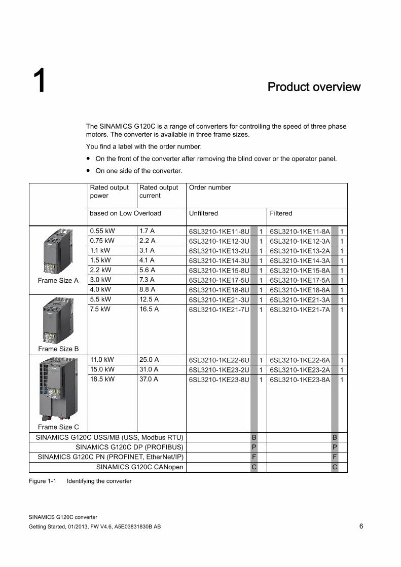
The SINAMICS G120C is a range of converters for controlling the speed of three phase motors. The converter is available in three frame sizes.
You find a label with the order number:
● On the front of the converter after removing the blind cover or the operator panel.
● On one side of the converter.
Figure 1-1 Identifying the converter

SINAMICS G120C converter Getting Started, 01/2013, FW V4.6, A5E03831830B AB 7
Safety notes 2
Use for the intended purpose The frequency converter described in this manual is a device for controlling an asynchronous low-voltage motor. The converter is designed for installation in electrical installations or machines.
It has been approved for industrial and commercial use on industrial networks. Its use in public line supplies requires a different configuration and/or additional measures.
The technical specifications and information about connection conditions are indicated on the rating plate and in the operating instructions.
DANGER
Danger to life when live parts are touched
Touching live parts can result in death or severe injury.
Note the following: Only work on electrical equipment if you are qualified to do so. When carrying out any work, always comply with the country-specific safety rules.
Follow the six steps to ensure safety: 1. Prepare for shutdown and inform team members who will be affected by the procedure. 2. Switch off the machine so that it is in a no-voltage state:
– Switch off the machine. – Wait until the discharge time specified on the warning labels has elapsed. – Check that it really is in a no-voltage condition, from phase conductor to phase
conductor and phase conductor to protective conductor. – Check that all auxiliary circuits are also in a no-voltage state. – Ensure that the motor cannot move.
3. Identify all other dangerous energy sources, e.g. compressed air, hydraulic systems or water.
4. Isolate or neutralize all hazardous energy sources by closing switches, grounding or short-circuiting or closing valves, for example.
5. Lock out all energy sources to prevent reclosing. 6. Make sure that the machine is completely locked out ... and that you have the right
machine!
After you have completed the work, restore operational readiness in the inverse sequence.

Safety notes
SINAMICS G120C converter 8 Getting Started, 01/2013, FW V4.6, A5E03831830B AB
WARNING
Danger to life when live parts are touched on damaged devices
Hazardous voltages can be present at the housing or exposed components on damaged devices. Ensure compliance with the limit values specified in the technical specifications during
transport, storage and operation. Do not use any damaged devices. The components must be protected against conductive contamination (e.g. by installing
them in a cabinet with degree of protection IP54B to EN 60529). Assuming that conductive contamination at the installation site can definitely be excluded, a lower degree of cabinet protection may be permitted.
WARNING Danger to life due to unexpected movement of machines when using mobile wireless devices or mobile phones
Using mobile radios or mobile phones with a transmit power > 1 W closer than approx. 2 m to the frequency converter may cause the devices to malfunction, affecting the functional safety of machines and, therefore, putting people at risk or causing material damage. Switch off mobile radios and mobile telephones when you are close to the converter.
NOTICE
Damage due to electric fields or electrostatic discharge
Electric fields or electrostatic discharge can result in malfunctions as a result of damaged individual components, integrated circuits, modules or devices. Package, store, transport and send the electronic components, modules or devices only
in the original product packaging or in other suitable materials, e.g. conductive foam rubber or aluminum foil.
Only touch components, modules and devices if you are grounded by means of one of the following measures: – Wearing an ESD armband or – Wearing ESD shoes or ESD grounding straps in ESD areas with conductive flooring
Only place electronic components, modules or devices on conductive surfaces (table with ESD surface, conductive ESD foam, ESD packaging, ESD transport container, for example).
Safety notes
SINAMICS G120C converter Getting Started, 01/2013, FW V4.6, A5E03831830B AB 9
CAUTION
Risk of burns due to touching hot surfaces
During operation and for a short time after the frequency converter shuts down, the surface of the device can reach a high temperature. Touching the surface of the converter can cause burns. Do not touch the device during operation. After shutting down the converter, wait for the device to cool down before touching it.
Residual risks of power drive systems The control and drive components of a drive system are approved for industrial and commercial use in industrial line supplies. Their use in public line supplies requires a different configuration and/or additional measures.
These components may only be operated in closed housings or in higher-level control cabinets with protective covers that are closed, and when all of the protective devices are used.
These components may only be handled by qualified and trained technical personnel who are knowledgeable and observe all of the safety instructions on the components and in the associated technical user documentation.
When assessing the machine's risk in accordance with the EC Machinery Directive, the machine manufacturer must take into account the following residual risks emanating from the control and drive components of a drive system:
1. Unintentional movements of driven machine components during commissioning, operation, maintenance, and repairs caused by, for example:
– Hardware defects and/or software errors in the sensors, controllers, actuators, and connection technology
– Response times of the controller and drive
– Operating and/or ambient conditions outside of the specification
– Condensation / conductive contamination
– Parameterization, programming, cabling, and installation errors
– Use of radio devices / cellular phones in the immediate vicinity of the controller
– External influences / damage
Safety notes
SINAMICS G120C converter 10 Getting Started, 01/2013, FW V4.6, A5E03831830B AB
2. In the event of a fault, exceptionally high temperatures, including an open fire, as well as emissions of light, noise, particles, gases, etc. can occur inside and outside the inverter, e.g.:
– Component malfunctions
– Software errors
– Operating and/or ambient conditions outside of the specification
– External influences / damage
Inverters of the Open Type / IP20 degree of protection must be installed in a metal control cabinet (or protected by another equivalent measure) such that the contact with fire inside and outside the inverter is not possible.
3. Hazardous shock voltages caused by, for example:
– Component malfunctions
– Influence of electrostatic charging
– Induction of voltages in moving motors
– Operating and/or ambient conditions outside of the specification
– Condensation / conductive contamination
– External influences / damage
4. Electrical, magnetic and electromagnetic fields generated in operation that can pose a risk to people with a pacemaker, implants or metal replacement joints, etc. if they are too close.
5. Release of environmental pollutants or emissions as a result of improper operation of the system and/or failure to dispose of components safely and correctly.
Note
The components must be protected against conductive contamination (e.g. by installing them in a control cabinet with degree of protection IP54 according to EN 60529).
Assuming that conductive contamination at the installation site can definitely be excluded, a lower degree of cabinet protection may be permitted.
For more information about residual risks of the components in a drive system, see the relevant sections in the technical user documentation.
SINAMICS G120C converter Getting Started, 01/2013, FW V4.6, A5E03831830B AB 11
Installing 33.1 Mechanical installation
WARNING Danger of fire spreading due to inadequate housing
Fire and smoke development can cause severe personal injury or material damage. Install devices without a protective housing in a metal control cabinet (or protect the
device by another equivalent measure) in such a way that contact with fire inside and outside the device is prevented.
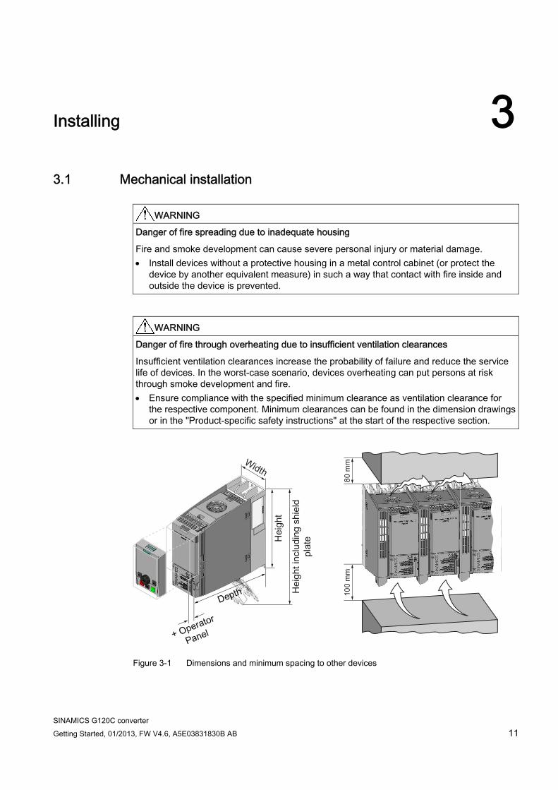
WARNING Danger of fire through overheating due to insufficient ventilation clearances
Insufficient ventilation clearances increase the probability of failure and reduce the service life of devices. In the worst-case scenario, devices overheating can put persons at risk through smoke development and fire. Ensure compliance with the specified minimum clearance as ventilation clearance for
the respective component. Minimum clearances can be found in the dimension drawings or in the "Product-specific safety instructions" at the start of the respective section.
Figure 3-1 Dimensions and minimum spacing to other devices

Installing 3.1 Mechanical installation
SINAMICS G120C converter 12 Getting Started, 01/2013, FW V4.6, A5E03831830B AB
Table 3- 1 Dimensions, drilling patterns, and fixing elements
Frame Size A 0.55 kW - 4.0 kW
Frame Size B 5.5 kW - 7.5 kW
Frame Size C 11 kW - 18.5 kW
Height 196 mm 196 mm 295 mm Height including shield plate 276 mm 276 mm 375 mm Width 73 mm 100 mm 140 mm Depth of the converter with PROFINET interface 225.4 mm 225.4 mm 225.4 mm Depth of the converter with USS/MB, CANopen, or PROFIBUS interface
203 mm 203 mm 203 mm
+ 21 mm when Operator Panel IOP (Intelligent Operator Panel) is attached
Additional depth when the Operator Panel is attached
+ 6 mm when Operator Panel BOP-2 (Basic Operator Panel) is attached
Drilling pattern
Fixing elements 3 x M4 studs, 3 x M4 nuts, 3 x M4 washers
4 x M4 studs, 4 x M4 nuts, 4 x M4 washers
4 x M5 studs, 4 x M5 nuts, 4 x M5 washers
Locked-rotor (starting) torque 2.5 Nm 2.5 Nm 2.5 Nm
Installing 3.2 Electrical installation
SINAMICS G120C converter Getting Started, 01/2013, FW V4.6, A5E03831830B AB 13
3.2 Electrical installation
3.2.1 Connecting the line supply, motor, and other components
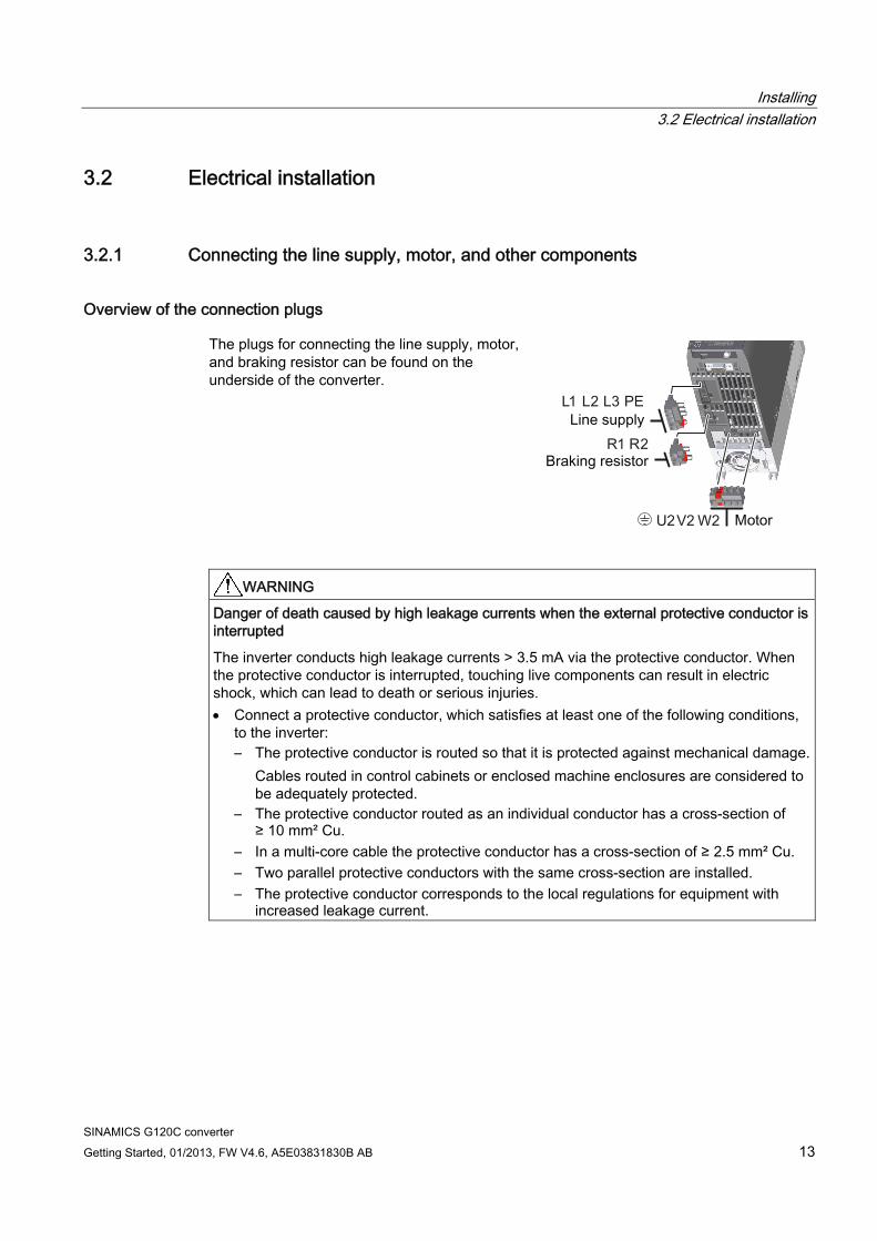
Overview of the connection plugs The plugs for connecting the line supply, motor, and braking resistor can be found on the underside of the converter.
WARNING Danger of death caused by high leakage currents when the external protective conductor is interrupted
The inverter conducts high leakage currents > 3.5 mA via the protective conductor. When the protective conductor is interrupted, touching live components can result in electric shock, which can lead to death or serious injuries. Connect a protective conductor, which satisfies at least one of the following conditions,
to the inverter: – The protective conductor is routed so that it is protected against mechanical damage.
Cables routed in control cabinets or enclosed machine enclosures are considered to be adequately protected.
– The protective conductor routed as an individual conductor has a cross-section of ≥ 10 mm² Cu.
– In a multi-core cable the protective conductor has a cross-section of ≥ 2.5 mm² Cu. – Two parallel protective conductors with the same cross-section are installed. – The protective conductor corresponds to the local regulations for equipment with
increased leakage current.

Installing 3.2 Electrical installation
SINAMICS G120C converter 14 Getting Started, 01/2013, FW V4.6, A5E03831830B AB
Connecting the converter and its components
Procedure
To connect the converter and its components, proceed as follows:
1. Check the table below to ensure you are using the correct fuses.
2. If you are using a line reactor or braking resistor, use the table below to check whether these components are suitable for the converter.
3. Connect the converter and its components.
4. If an EMC-compliant installation is required, you must use shielded cables. Refer also to section: Installing the converter in compliance with EMC rules (Page 24).
You have now connected the converter and its components.
Installing 3.2 Electrical installation
SINAMICS G120C converter Getting Started, 01/2013, FW V4.6, A5E03831830B AB 15
Components for United States / Canadian installations (UL/CSA) This equipment is capable of providing internal motor overload protection according to UL508C. Take the following actions In order to comply with UL508C:
● Use UL/CSA-certified J-type fuses, overload circuit-breakers or intrinsically safe motor protection devices.
● For each frame size A to C use class 1 75° C copper wire only.
● Install the converter with any external recommended suppressor with the following features:
– Surge-protective devices; device shall be a Listed Surge-protective device (Category code VZCA and VZCA7).
– Rated nominal voltage 480/277 VAC, 50/60 Hz, 3-phase.
– Clamping voltage VPR = 2000 V, IN = 3 kA min, MCOV = 508 VAC, SCCR = 40 kA.
– Suitable for Type 1 or Type 2 SPD application.
– Clamping shall be provided between phases and also between phase and ground.
● Do not change the parameter p0610 (factory setting of p0610 = 12 means: the drive reacts on a motor overtemperature with an immediate alarm and after a certain time with a fault).
Installing 3.2 Electrical installation
SINAMICS G120C converter 16 Getting Started, 01/2013, FW V4.6, A5E03831830B AB
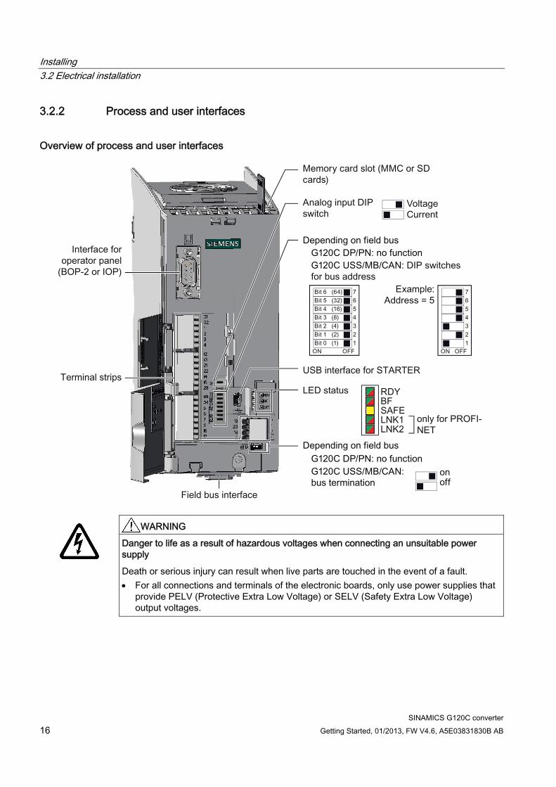
3.2.2 Process and user interfaces
Overview of process and user interfaces
WARNING
Danger to life as a result of hazardous voltages when connecting an unsuitable power supply
Death or serious injury can result when live parts are touched in the event of a fault. For all connections and terminals of the electronic boards, only use power supplies that
provide PELV (Protective Extra Low Voltage) or SELV (Safety Extra Low Voltage) output voltages.

Installing 3.2 Electrical installation
SINAMICS G120C converter Getting Started, 01/2013, FW V4.6, A5E03831830B AB 17
Wiring variations of the terminal strips
① The analog input is supplied from the internal 10 V voltage. ② The analog input is supplied from an external 10 V source. ③ Wiring when using the internal power supplies. Connecting a contact that switches to P potential. ④ Wiring when using external power supplies. Connecting a contact that switches to P potential. ⑤ Wiring when using the internal power supplies. Connecting a contact that switches to M potential. ⑥ Wiring when using external power supplies. Connecting a contact that switches to M potential.
3.2.3 Finding a suitable setting for the interfaces The inputs and outputs of the frequency inverter and the fieldbus interface have specific functions when set to the factory settings.
When you put the frequency inverter into operation, you can change the function of each of its inputs and outputs and the setting of the fieldbus interface.
To make the setting process easier, the inverter has various predefined assignments (macros).
Only the inputs and outputs whose functions change by selecting a specific assignment, are shown on the following pages.

Installing 3.2 Electrical installation
SINAMICS G120C converter 18 Getting Started, 01/2013, FW V4.6, A5E03831830B AB
Procedure
To select one of the inverter's pre-assigned settings, proceed as follows:
1. Think about which of the input and output functions you are using in the application.
2. Find the I/O configuration (macro) that best suits your application.
3. Note the macro number of the corresponding default setting.
You must set this macro number when putting the frequency inverter into operation.
You have found the appropriate inverter pre-assignment.
Macro 1: Two fixed speeds Macro 2: Two fixed speeds with safety
function Macro 3: Four fixed speeds
DI 4 and DI 5 = high: The converter adds both fixed speeds.
DI 0 and DI 1 = high: The converter adds both fixed speeds.
Multiple DIs = high: The converter adds the corresponding fixed speeds.
Macro 4: PROFIBUS or PROFINET Macro 5: PROFIBUS or PROFINET
with safety function
PROFIdrive telegram 352
PROFIdrive telegram 1

Installing 3.2 Electrical installation
SINAMICS G120C converter Getting Started, 01/2013, FW V4.6, A5E03831830B AB 19
Macro 7: Switching between fieldbus and jog via DI 3
Factory setting for converters with PROFIBUS or PROFINET interface Macro 8: Motorized potentiometer
(MOP) with safety function
PROFIdrive telegram 1
Macro 9: Motorized potentiometer
(MOP) Macro 12: Two-wire control using
method 1 Factory setting for converters without PROFIBUS or PROFINET interface.
Macro 13: Setpoint via analog input with safety function
Installing 3.2 Electrical installation
SINAMICS G120C converter 20 Getting Started, 01/2013, FW V4.6, A5E03831830B AB
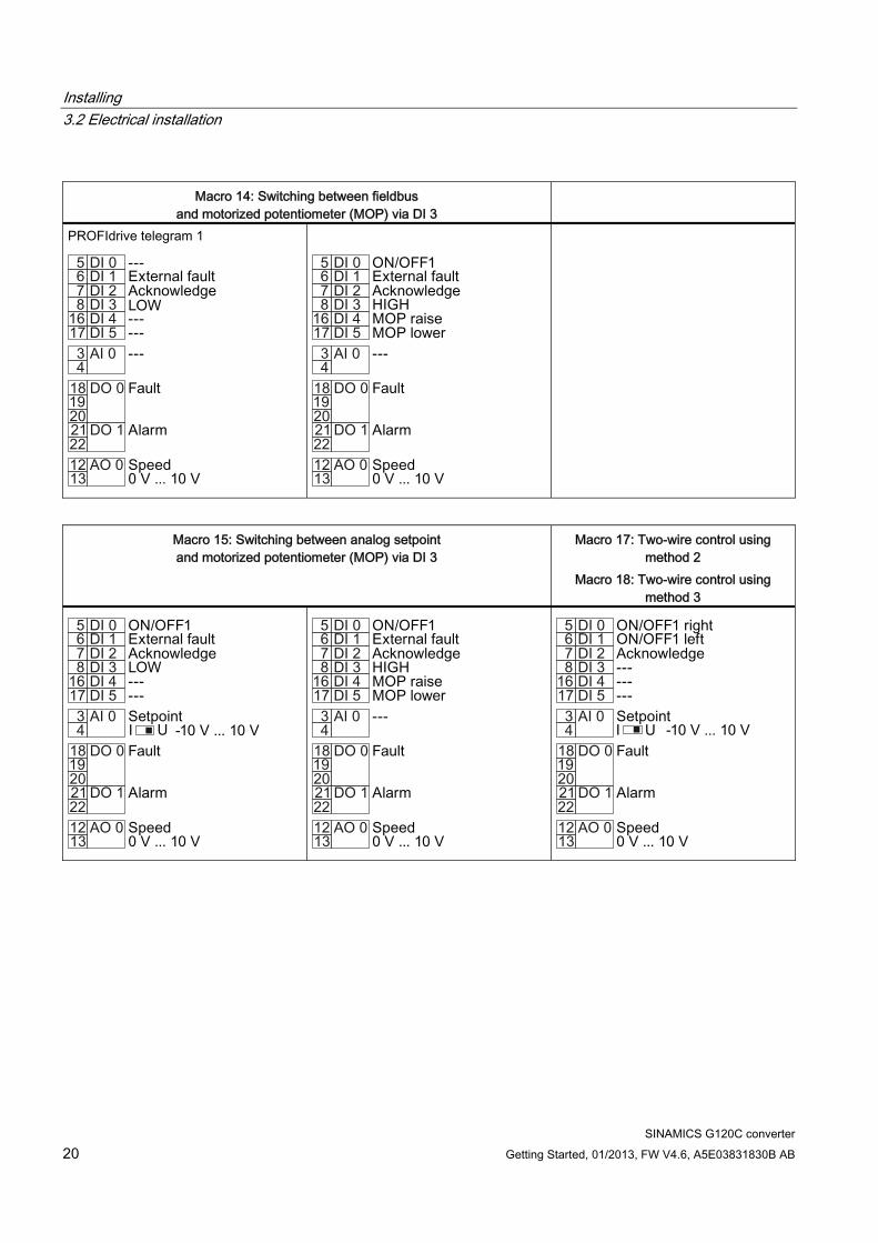
Macro 14: Switching between fieldbus
and motorized potentiometer (MOP) via DI 3
PROFIdrive telegram 1
Macro 15: Switching between analog setpoint and motorized potentiometer (MOP) via DI 3
Macro 17: Two-wire control using method 2
Macro 18: Two-wire control using method 3

Installing 3.2 Electrical installation
SINAMICS G120C converter Getting Started, 01/2013, FW V4.6, A5E03831830B AB 21
Macro 19: Three-wire control using
method 1 Macro 20: Three-wire control using
method 2 Macro 21: USS fieldbus
Macro 22: CANopen fieldbus
USS setting: 38,400 baud, 2 PZD, PKW variable CANopen setting: 20 kBaud
3.2.4 Wiring the terminal strip
NOTICE Damage to the inverter when using long signal cables
Using long cables at the inverter's digital inputs and 24 V power supply can lead to overvoltage during switching operations. Overvoltage can damage the inverter. If you use cables of more than 30 m at the digital inputs and 24 V power supply, connect
an overvoltage protection element between the terminal and the associated reference potential. We recommend using the Weidmüller overvoltage protection terminal with designation MCZ OVP TAZ DIODE 24VDC.
Prerequisites
● Use suitable cables:
– Solid or flexible cables.
– Suitable cable cross-section: 0.5 mm² (21 AWG) to 1.5 mm² (16 AWG).
When completely connecting up the unit, we recommend cables with a cross-section of 1 mm² (18 AWG).
● Do not use wire end ferrules.

Installing 3.2 Electrical installation
SINAMICS G120C converter 22 Getting Started, 01/2013, FW V4.6, A5E03831830B AB
● You have found an appropriate pre-assignment for the terminal strips, which you can now use to wire the inverter.
See also Section: Finding a suitable setting for the interfaces (Page 17).
● You have the appropriate tools:
– Small screwdriver to open the spring-loaded terminals
– Tool for stripping the cables
Procedure
To wire the inverter's terminal strip, proceed as follows:
1. Remove the last 10 mm (approx.) of the cable insulation.
2. Using the screwdriver, press on the orange operator control of the spring-loaded terminal hard enough to open the terminal.
3. Insert the cable into the terminal as far as it will go and remove the screwdriver.
4. Ensure that the cable is securely connected by pulling on it lightly.
5. Wire all the required terminals on the strip in this way.
6. Route the signal cables in such a way that you can completely close the front doors after wiring the terminal strip.
7. If you use shielded cables, then you must connect the shield to the mounting plate of the control cabinet or with the shield support of the inverter through a good electrical connection and a large surface area. See also: Installing the converter in compliance with EMC rules (Page 24)
8. Use a cable grip.
You have now wired the inverter's terminal strips.
Installing 3.2 Electrical installation
SINAMICS G120C converter Getting Started, 01/2013, FW V4.6, A5E03831830B AB 23
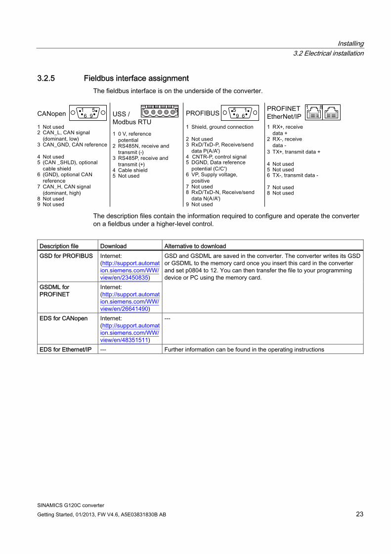
3.2.5 Fieldbus interface assignment The fieldbus interface is on the underside of the converter.
The description files contain the information required to configure and operate the converter on a fieldbus under a higher-level control.
Description file Download Alternative to download GSD for PROFIBUS Internet:
(http://support.automation.siemens.com/WW/view/en/23450835)
GSDML for PROFINET
Internet: (http://support.automation.siemens.com/WW/view/en/26641490)
GSD and GSDML are saved in the converter. The converter writes its GSD or GSDML to the memory card once you insert this card in the converter and set p0804 to 12. You can then transfer the file to your programming device or PC using the memory card.
EDS for CANopen Internet: (http://support.automation.siemens.com/WW/view/en/48351511)
---
EDS for Ethernet/IP --- Further information can be found in the operating instructions
Installing 3.2 Electrical installation
SINAMICS G120C converter 24 Getting Started, 01/2013, FW V4.6, A5E03831830B AB
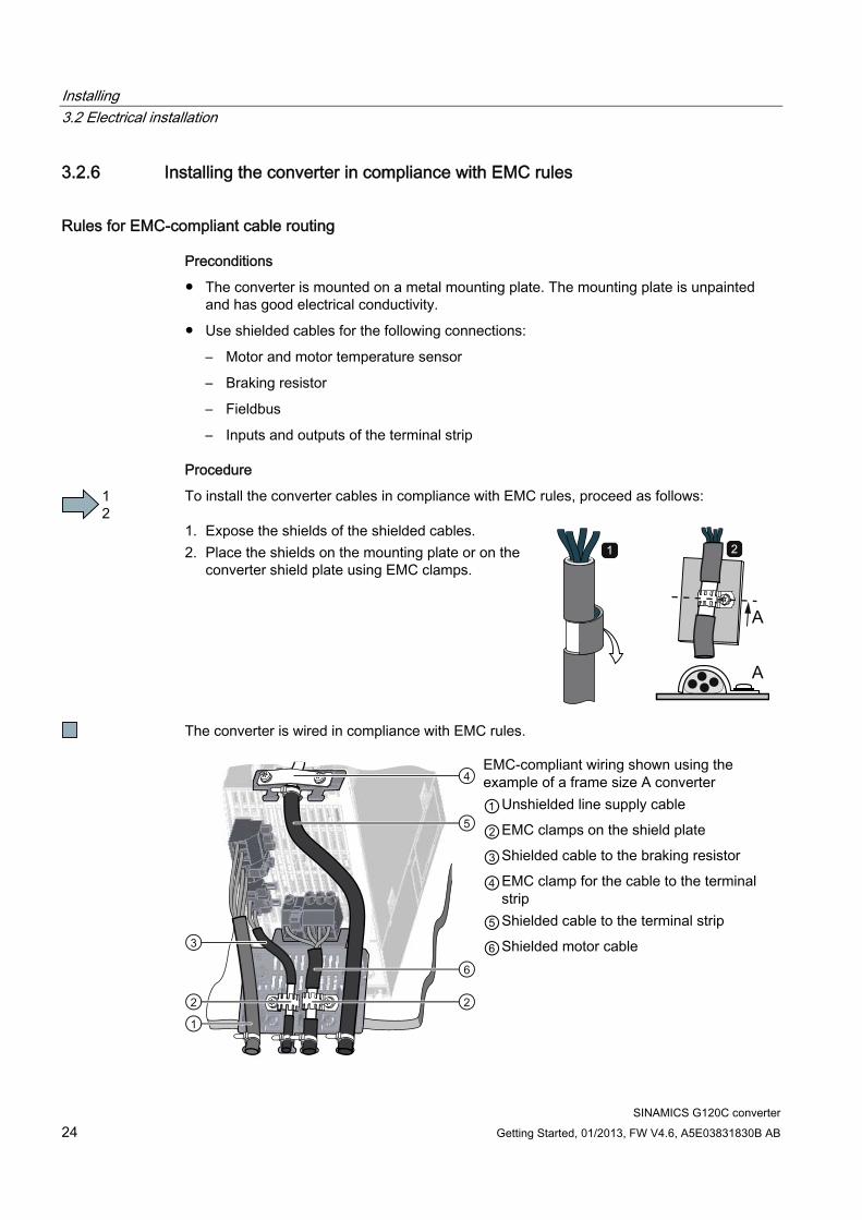
3.2.6 Installing the converter in compliance with EMC rules
Rules for EMC-compliant cable routing
Preconditions
● The converter is mounted on a metal mounting plate. The mounting plate is unpainted and has good electrical conductivity.
● Use shielded cables for the following connections:
– Motor and motor temperature sensor
– Braking resistor
– Fieldbus
– Inputs and outputs of the terminal strip
Procedure
To install the converter cables in compliance with EMC rules, proceed as follows: 1. Expose the shields of the shielded cables. 2. Place the shields on the mounting plate or on the
converter shield plate using EMC clamps.
The converter is wired in compliance with EMC rules.
EMC-compliant wiring shown using the example of a frame size A converter ①Unshielded line supply cable
②EMC clamps on the shield plate
③Shielded cable to the braking resistor
④EMC clamp for the cable to the terminal strip
⑤Shielded cable to the terminal strip
⑥Shielded motor cable

SINAMICS G120C converter Getting Started, 01/2013, FW V4.6, A5E03831830B AB 25
Commissioning 44.1 Overview of commissioning tools
Accessories for commissioning and data backup Operator Panels for commissioning, diagnostics and controlling inverters Order number
BOP-2 (Basic Operator Panel) - for snapping onto the frequency inverter Copying of drive parameters Two-line display Guided basic commissioning
6SL3255-0AA00-4CA1
IOP (Intelligent Operator Panel) - for snapping onto the frequency inverter Copying of drive parameters Plain text display Menu-based operation and application wizards
6SL3255-0AA00-4JA0
Door mounting kit for IOP/BOP-2 For installation of theBOP-2 or IOP in a control cabinet
door. Degree of protection with IOP: IP54 or UL Type 12 Degree of protection with BOP-2: IP55
6SL3256-0AP00-0JA0
IOP - with handheld For mobile use of the IOP
6SL3255-0AA00-4HA0
PC tools for commissioning, diagnostics and controlling of the converter
STARTERSTARTER
PC Connection Kit Includes a STARTER DVD and USB port.
6SL3255-0AA00-2CA0
Commissioning 4.1 Overview of commissioning tools
SINAMICS G120C converter 26 Getting Started, 01/2013, FW V4.6, A5E03831830B AB
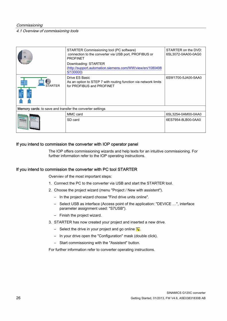
STARTER Commissioning tool (PC software) connection to the converter via USB port, PROFIBUS or PROFINET Downloading: STARTER (http://support.automation.siemens.com/WW/view/en/10804985/130000)
STARTER on the DVD: 6SL3072-0AA00-0AG0
Drive ES Basic As an option to STEP 7 with routing function via network limits for PROFIBUS and PROFINET
6SW1700-5JA00-5AA0
Memory cards: to save and transfer the converter settings MMC card 6SL3254-0AM00-0AA0
SD card 6ES7954-8LB00-0AA0
If you intend to commission the converter with IOP operator panel The IOP offers commissioning wizards and help texts for an intuitive commissioning. For further information refer to the IOP operating instructions.
If you intend to commission the converter with PC tool STARTER Overviev of the most important steps:
1. Connect the PC to the converter via USB and start the STARTER tool.
2. Choose the project wizard (menu "Project / New with assistent").
– In the project wizard choose "Find drive units online".
– Select USB as interface (Access point of the application: "DEVICE …", interface parameter assignment used: "S7USB").
– Finish the project wizard.
3. STARTER has now created your project and inserted a new drive.
– Select the drive in your project and go online .
– In your drive open the "Configuration" mask (double click).
– Start commissioning with the "Assistent" button.
For further information refer to converter operating instructions.
Commissioning 4.2 Commissioning with BOP-2 operator panel
SINAMICS G120C converter Getting Started, 01/2013, FW V4.6, A5E03831830B AB 27
4.2 Commissioning with BOP-2 operator panel
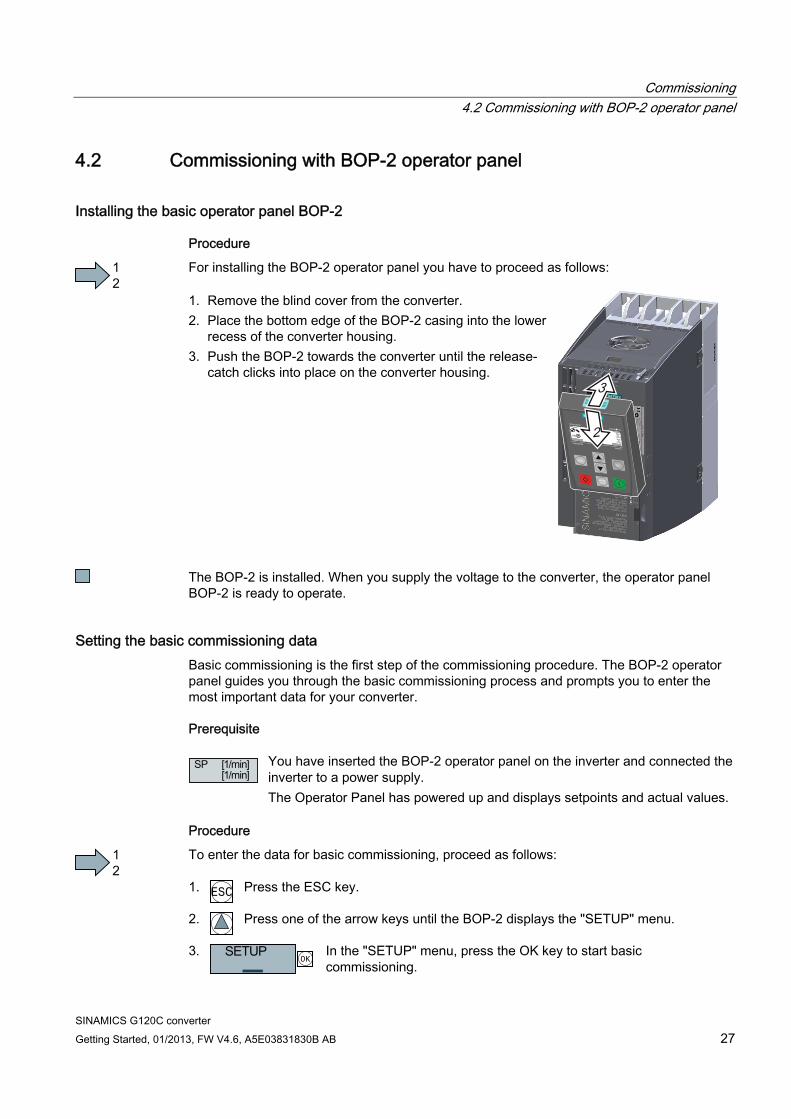
Installing the basic operator panel BOP-2
Procedure
For installing the BOP-2 operator panel you have to proceed as follows: 1. Remove the blind cover from the converter. 2. Place the bottom edge of the BOP-2 casing into the lower
recess of the converter housing. 3. Push the BOP-2 towards the converter until the release-
catch clicks into place on the converter housing.
The BOP-2 is installed. When you supply the voltage to the converter, the operator panel BOP-2 is ready to operate.
Setting the basic commissioning data Basic commissioning is the first step of the commissioning procedure. The BOP-2 operator panel guides you through the basic commissioning process and prompts you to enter the most important data for your converter.
Prerequisite
You have inserted the BOP-2 operator panel on the inverter and connected the inverter to a power supply. The Operator Panel has powered up and displays setpoints and actual values.
Procedure
To enter the data for basic commissioning, proceed as follows: 1. ESC
Press the ESC key.
2.
Press one of the arrow keys until the BOP-2 displays the "SETUP" menu.
3. OK
In the "SETUP" menu, press the OK key to start basic commissioning.
Commissioning 4.2 Commissioning with BOP-2 operator panel
SINAMICS G120C converter 28 Getting Started, 01/2013, FW V4.6, A5E03831830B AB
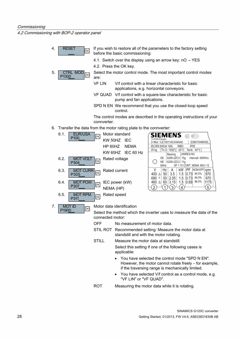
4. OK
If you wish to restore all of the parameters to the factory setting before the basic commissioning:
4.1. Switch over the display using an arrow key: nO → YES 4.2. Press the OK key. 5. Select the motor control mode. The most important control modes
are: VF LIN V/f control with a linear characteristic for basic
applications, e.g. horizontal conveyors. VF QUAD V/f control with a square-law characteristic for basic
pump and fan applications. SPD N EN We recommend that you use the closed-loop speed
control.
OK
The control modes are described in the operating instructions of your connverter.
6. Transfer the data from the motor rating plate to the connverter: 6.1. Motor standard KW 50HZ IEC HP 60HZ NEMA
OK
KW 60HZ IEC 60 Hz 6.2.
OK
Rated voltage
6.3. OK
Rated current
6.4. OK
IEC power (kW) NEMA (HP)
6.5. OK
Rated speed
84.5%84.5%86.5%
NOM.EFF
IP55 E0807/0496382_
IMB3
UNIREX-N340°C Tamb Th.Cl. 155(F)25 kg
MG1-12 NEMASF 1.15 CONT60Hz:
Intervall: 4000hrs
IEC/EN 60034 100L3~Mot. 1LE10011AC434AA0
6206-2ZC36206-2ZC3Bearing
DENE 11g
15g
D-91056 Erlangen
-20°C
Y400
460690
V970970
1175
rpm0.730.730.69
PF
3.15
3.52.05
A kWHz50
6050
1.5
1.51.5
7. Motor data identification Select the method which the inverter uses to measure the data of the connected motor:
OFF No measurement of motor data. STIL ROT Recommended setting: Measure the motor data at
standstill and with the motor rotating. STILL Measure the motor data at standstill.
Select this setting if one of the following cases is applicable: You have selected the control mode "SPD N EN".
However, the motor cannot rotate freely – for example, if the traversing range is mechanically limited.
You have selected V/f control as a control mode, e.g. "VF LIN" or "VF QUAD".
OK
ROT Measuring the motor data while it is rotating.
Commissioning 4.2 Commissioning with BOP-2 operator panel
SINAMICS G120C converter Getting Started, 01/2013, FW V4.6, A5E03831830B AB 29
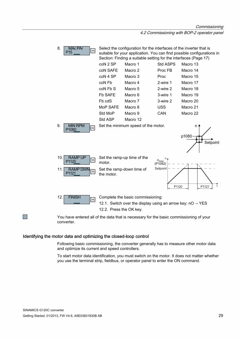
8. Select the configuration for the interfaces of the inverter that is suitable for your application. You can find possible configurations in Section: Finding a suitable setting for the interfaces (Page 17)
coN 2 SP Macro 1 Std ASPS Macro 13 coN SAFE Macro 2 Proc FB Macro 14 coN 4 SP Macro 3 Proc Macro 15 coN Fb Macro 4 2-wire 1 Macro 17 coN Fb S Macro 5 2-wire 2 Macro 18 Fb SAFE Macro 6 3-wire 1 Macro 19 Fb cdS Macro 7 3-wire 2 Macro 20 MoP SAFE Macro 8 USS Macro 21 Std MoP Macro 9 CAN Macro 22
OK
Std ASP Macro 12 9.
OK
Set the minimum speed of the motor.
10.
OK
Set the ramp-up time of the motor.
11. OK
Set the ramp-down time of the motor.
12. Complete the basic commissioning: 12.1. Switch over the display using an arrow key: nO → YES
OK
12.2. Press the OK key.
You have entered all of the data that is necessary for the basic commissioning of your converter.
Identifying the motor data and optimizing the closed-loop control Following basic commissioning, the converter generally has to measure other motor data and optimize its current and speed controllers.
To start motor data identification, you must switch on the motor. It does not matter whether you use the terminal strip, fieldbus, or operator panel to enter the ON command.
Commissioning 4.2 Commissioning with BOP-2 operator panel
SINAMICS G120C converter 30 Getting Started, 01/2013, FW V4.6, A5E03831830B AB
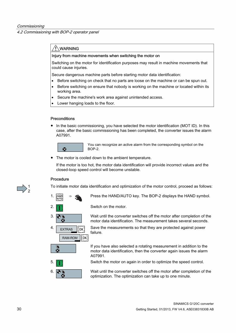
WARNING Injury from machine movements when switching the motor on
Switching on the motor for identification purposes may result in machine movements that could cause injuries.
Secure dangerous machine parts before starting motor data identification: Before switching on check that no parts are loose on the machine or can be spun out. Before switching on ensure that nobody is working on the machine or located within its
working area. Secure the machine's work area against unintended access. Lower hanging loads to the floor.
Preconditions
● In the basic commissioning, you have selected the motor identification (MOT ID). In this case, after the basic commissioning has been completed, the converter issues the alarm A07991.
You can recognize an active alarm from the corresponding symbol on the BOP-2.
● The motor is cooled down to the ambient temperature.
If the motor is too hot, the motor data identification will provide incorrect values and the closed-loop speed control will become unstable.
Procedure
To initiate motor data identification and optimization of the motor control, proceed as follows: 1.
⇒
Press the HAND/AUTO key. The BOP-2 displays the HAND symbol.
2.
Switch on the motor.
3.
Wait until the converter switches off the motor after completion of the motor data identification. The measurement takes several seconds.
4.
OK
OK
Save the measurements so that they are protected against power failure.
If you have also selected a rotating measurement in addition to the motor data identification, then the converter again issues the alarm A07991.
5.
Switch the motor on again in order to optimize the speed control.
6.
Wait until the converter switches off the motor after completion of the optimization. The optimization can take up to one minute.
Commissioning 4.3 Further settings
SINAMICS G120C converter Getting Started, 01/2013, FW V4.6, A5E03831830B AB 31
7.
Switch the converter control from HAND to AUTO.
8.
OK
OK
Save the measurements so that they are protected against power failure.
You have now completed motor data identification and the closed-loop speed control has been optimized.
4.3 Further settings
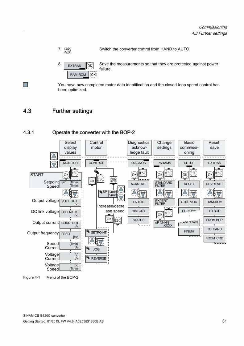
4.3.1 Operate the converter with the BOP-2
OK ESCOK ESC OK ESC OK ESC
OK ESC
OK ESC
OK ESC OK ESC
Figure 4-1 Menu of the BOP-2
Commissioning 4.3 Further settings
SINAMICS G120C converter 32 Getting Started, 01/2013, FW V4.6, A5E03831830B AB
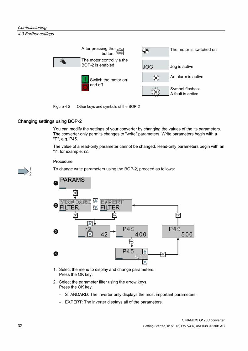
Figure 4-2 Other keys and symbols of the BOP-2
Changing settings using BOP-2 You can modify the settings of your converter by changing the values of the its parameters. The converter only permits changes to "write" parameters. Write parameters begin with a "P", e.g. P45.
The value of a read-only parameter cannot be changed. Read-only parameters begin with an "r", for example: r2.
Procedure
To change write parameters using the BOP-2, proceed as follows:
OK
OK
OK
OK OK ESC
1. Select the menu to display and change parameters.
Press the OK key.
2. Select the parameter filter using the arrow keys. Press the OK key.
– STANDARD: The inverter only displays the most important parameters.
– EXPERT: The inverter displays all of the parameters.
Commissioning 4.3 Further settings
SINAMICS G120C converter Getting Started, 01/2013, FW V4.6, A5E03831830B AB 33
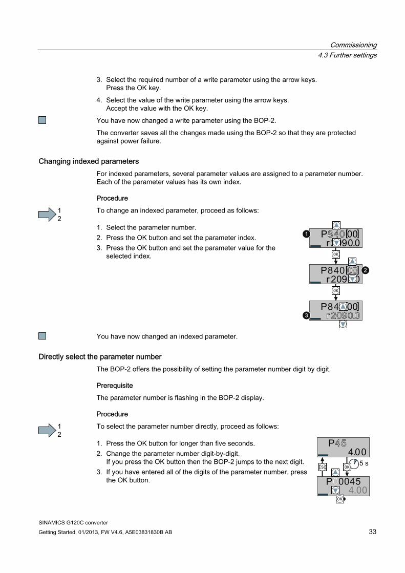
3. Select the required number of a write parameter using the arrow keys. Press the OK key.
4. Select the value of the write parameter using the arrow keys. Accept the value with the OK key.
You have now changed a write parameter using the BOP-2.
The converter saves all the changes made using the BOP-2 so that they are protected against power failure.
Changing indexed parameters For indexed parameters, several parameter values are assigned to a parameter number. Each of the parameter values has its own index.
Procedure
To change an indexed parameter, proceed as follows: 1. Select the parameter number. 2. Press the OK button and set the parameter index. 3. Press the OK button and set the parameter value for the
selected index. OK
OK
You have now changed an indexed parameter.
Directly select the parameter number The BOP-2 offers the possibility of setting the parameter number digit by digit.
Prerequisite
The parameter number is flashing in the BOP-2 display.
Procedure
To select the parameter number directly, proceed as follows: 1. Press the OK button for longer than five seconds. 2. Change the parameter number digit-by-digit.
If you press the OK button then the BOP-2 jumps to the next digit. 3. If you have entered all of the digits of the parameter number, press
the OK button.
OK
OKESC

Commissioning 4.3 Further settings
SINAMICS G120C converter 34 Getting Started, 01/2013, FW V4.6, A5E03831830B AB
You have now entered the parameter number directly.
Entering the parameter value directly The BOP-2 offers the option of setting the parameter value digit by digit.
Prerequisite
The parameter value flashes in the BOP-2 display.
Procedure
To select the parameter value directly, proceed as follows: 1. Press the OK button for longer than five seconds. 2. Change the parameter value digit-by-digit.
If you press the OK button then the BOP-2 jumps to the next digit. 3. If you have entered all of the digits of the parameter value, press the
OK button.
OKESC
OK
You have now entered the parameter value directly.
When must you not change a parameter? The converter indicates why it currently does not permit a parameter to be changed:
OK
OK
OK
You have attempted to change
a read-only parameter. You must change to basic commissioning to set this
parameter.
You must turn the motor off to set this parameter.
The operating state in which you can change a parameter is provided in the List Manual for each parameter.

Commissioning 4.3 Further settings
SINAMICS G120C converter Getting Started, 01/2013, FW V4.6, A5E03831830B AB 35
4.3.2 Changing the function of terminals To change the function of a terminal you must set the terminal's signal connection in the converter.
Overview Procedure Example
Digital input
1. Select the required function marked using a "BI" parameter.
2. Set this parameter to the value of the status parameter r0722.x of the required digital input.
You have changed the function of the digital input.
You want to switch on the motor via DI2
r0722.2 722.2p0840
Setting process with the BOP-2:
If you want to switch the converter's master control (e.g., when selecting macro 7), you must set the correct parameter index. Index 0 (e.g., P840[00]) applies for the interface assignment on the left side of the
macro illustration. Index 1 (e.g., P840[01]) applies for the interface assignment on the right side of
the macro illustration. See also Section: Finding a suitable setting for the interfaces (Page 17). Analog input
1. Select the required function marked using a "CI" parameter.
2. Set this parameter to the value of status parameter r0755.x of the analog input.
3. Determine whether the analog input is a current or a voltage input: – Set the I/U switch on the
front of the converter in the correct position.
– Set the p0756[00] parameter to the corresponding value.
You have changed the function of the analog input.
You want to specify the setpoint of the technology controller via AI 0
r0755 755[0]p1075
Setting process with the BOP-2:
r0755CI: pyyyy
CO: rxxyyp0771
r0722.0r0722.1r0722.2r0722.3r0722.4r0722.5
BI: pxxxx
BO: ryyxx.n
p0731
p0730
If you want to switch the converter's master control (e.g., when selecting macro 7), you must set the correct parameter index: Index 0 (e.g., P2253[00]) applies for the interface assignment on the left side of
the macro illustration. Index 1 (e.g., P2253[01]) applies for the interface assignment on the right side of
the macro illustration. See also Section: Finding a suitable setting for the interfaces (Page 17).
Commissioning 4.3 Further settings
SINAMICS G120C converter 36 Getting Started, 01/2013, FW V4.6, A5E03831830B AB
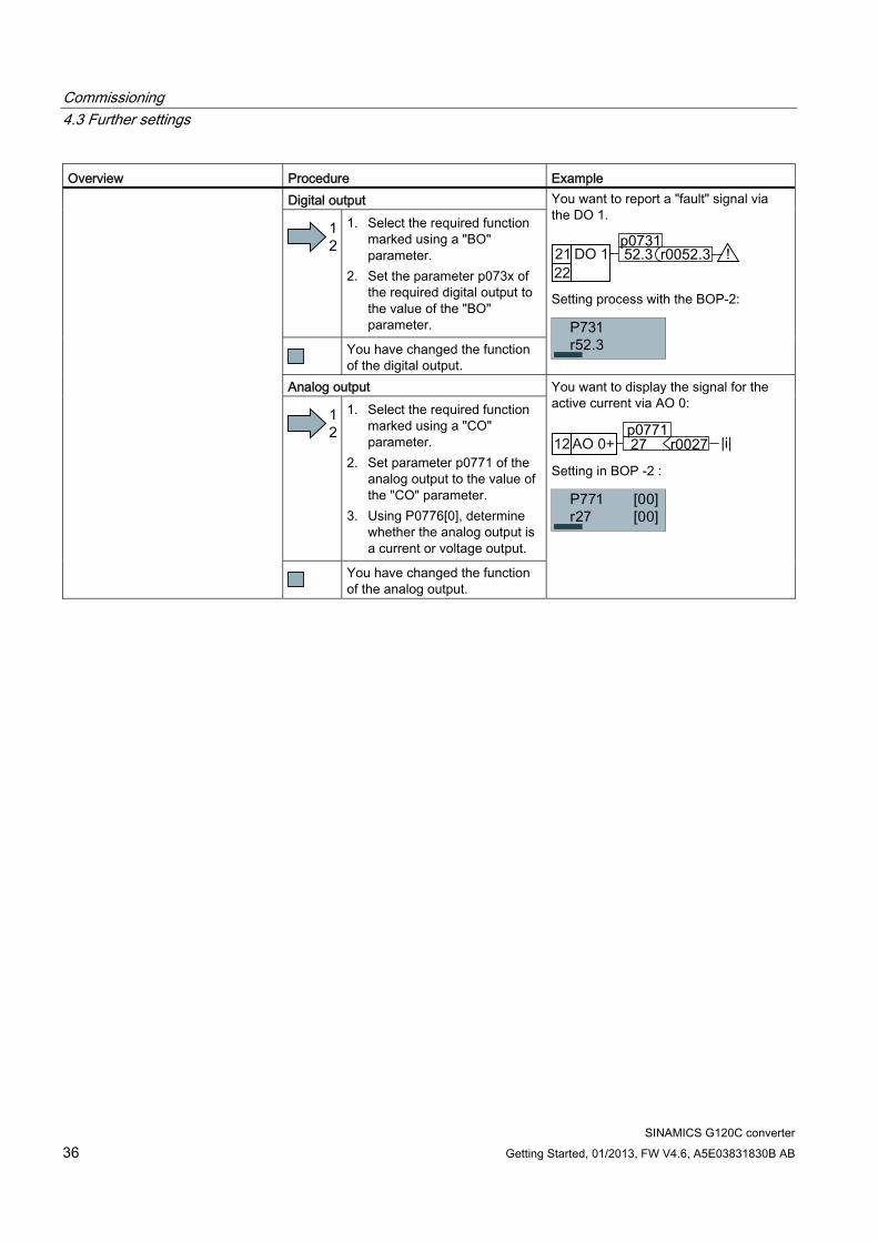
Overview Procedure Example Digital output
1. Select the required function marked using a "BO" parameter.
2. Set the parameter p073x of the required digital output to the value of the "BO" parameter.
You have changed the function of the digital output.
You want to report a "fault" signal via the DO 1.
r0052.352.3p0731
Setting process with the BOP-2:
Analog output
1. Select the required function marked using a "CO" parameter.
2. Set parameter p0771 of the analog output to the value of the "CO" parameter.
3. Using P0776[0], determine whether the analog output is a current or voltage output.
You have changed the function of the analog output.
You want to display the signal for the active current via AO 0:
r0027 |i|27p0771
Setting in BOP -2 :
Commissioning 4.3 Further settings
SINAMICS G120C converter Getting Started, 01/2013, FW V4.6, A5E03831830B AB 37
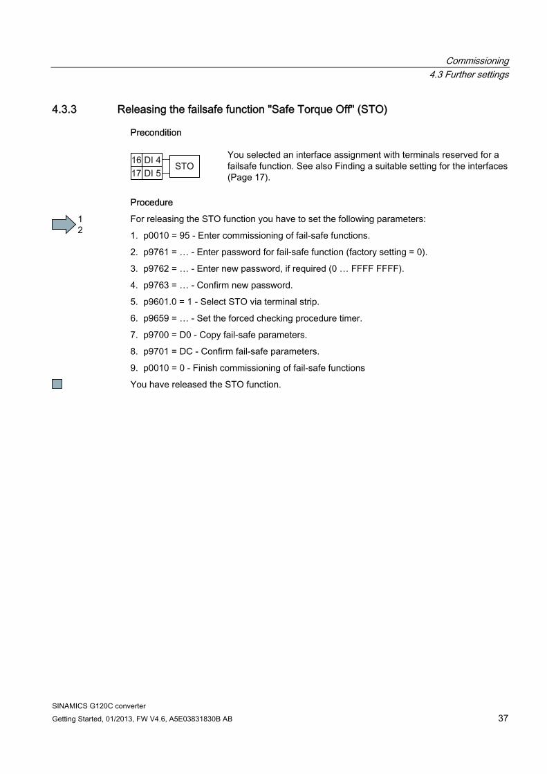
4.3.3 Releasing the failsafe function "Safe Torque Off" (STO)
Precondition
You selected an interface assignment with terminals reserved for a failsafe function. See also Finding a suitable setting for the interfaces(Page 17).
Procedure
For releasing the STO function you have to set the following parameters:
1. p0010 = 95 - Enter commissioning of fail-safe functions.
2. p9761 = … - Enter password for fail-safe function (factory setting = 0).
3. p9762 = … - Enter new password, if required (0 … FFFF FFFF).
4. p9763 = … - Confirm new password.
5. p9601.0 = 1 - Select STO via terminal strip.
6. p9659 = … - Set the forced checking procedure timer.
7. p9700 = D0 - Copy fail-safe parameters.
8. p9701 = DC - Confirm fail-safe parameters.
9. p0010 = 0 - Finish commissioning of fail-safe functions
You have released the STO function.

SINAMICS G120C converter Getting Started, 01/2013, FW V4.6, A5E03831830B AB 38
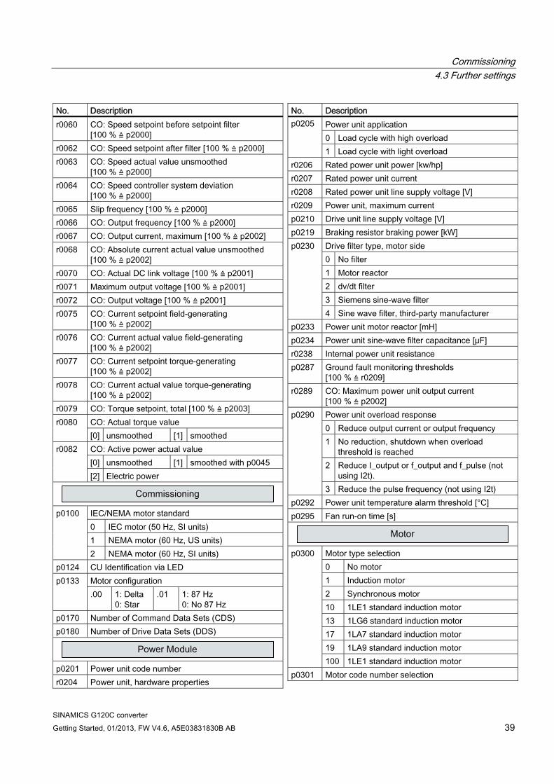
4.3.4 Parameter list The following list contains the basic parameter information with access level 1 … 3. The complete parameter list is provided in the list manual, see Product support (Page 58). No. Description
r0002 Drive operating display p0003 Access level p0010 Drive, commissioning parameter filter p0015 Macro drive unit
See also Finding a suitable setting for the interfaces (Page 17).
r0018 Control Unit firmware version r0020 Speed setpoint smoothed [100 % ≙ p2000] r0021 CO: Actual speed smoothed [100 % ≙ p2000] r0022 Speed actual value rpm smoothed [rpm] r0024 Output frequency smoothed [100 % ≙ p2000] r0025 CO: Output voltage smoothed [100 % ≙ p2001] r0026 CO: DC link voltage smoothed [100 % ≙ p2001] r0027 CO: Absolute actual current smoothed
[100 % ≙ p2002] r0031 Actual torque smoothed [100 % ≙ p2003] r0032 CO: Active power actual value smoothed
[100 % ≙ r2004] r0034 Motor utilization [100 ≙ 100%] r0035 CO: Motor temperature [100°C ≙ p2006] r0036 CO: Power unit overload I2t [100 ≙ 100%] r0039 Energy consumption p0040 0 → 1 Reset the energy consumption display r0041 Energy usage saved/energy saved p0045 Smoothing time constant, display values [ms] r0046 CO/BO: Missing enable signals r0047 Motor data identification routine and speed
controller optimization r0050 CO/BO: Command Data Set CDS effective r0051 CO/BO: Drive Data Set DDS effective
CO/BO: Status word 1 .00 Ready to start .01 Ready .02 Operation enabled .03 Fault active .04 Coast down active (OFF2)
r0052
.05 Quick stop active (OFF3)
No. Description .06 Closing lockout active .07 Alarm active .08 Deviation, setpoint/actual speed .09 Control requested .10 Maximum speed reached .11 I,M,P limit reached .12 Motor holding brake open .13 Alarm overtemperature motor .14 Motor rotates forwards .15 Alarm inverter overload
r0053 CO/BO: Status word 2 CO/BO: Control word 1 .00 ON/OFF1 .01 OFF2 .02 OFF3 .03 Enable ramp-function generator .04 Enable ramp-function generator .05 Continue ramp-function generator .06 Enable speed setpoint .07 Acknowledge fault .08 Jog bit 0 .09 Jog bit 1 .10 Master control by PLC .11 Direction reversal (setpoint) .13 Motorized potentiometer, raise .14 Motorized potentiometer, lower
r0054
.15 CDS bit 0 CO/BO: Supplementary control word .00 Fixed setpoint, bit 0 .01 Fixed setpoint, bit 1 .02 Fixed setpoint, bit 2 .03 Fixed setpoint, bit 3 .04 DDS selection, bit 0 .05 DDS selection, bit 1 .08 Technology controller enable .09 DC braking enable .11 Droop enable .12 Closed-loop torque control active .13 External fault 1 (F07860)
r0055
.15 CDS bit 1 r0056 CO/BO: Status word, closed-loop control
Commissioning 4.3 Further settings
SINAMICS G120C converter Getting Started, 01/2013, FW V4.6, A5E03831830B AB 39
No. Description r0060 CO: Speed setpoint before setpoint filter
[100 % ≙ p2000] r0062 CO: Speed setpoint after filter [100 % ≙ p2000] r0063 CO: Speed actual value unsmoothed
[100 % ≙ p2000] r0064 CO: Speed controller system deviation
[100 % ≙ p2000] r0065 Slip frequency [100 % ≙ p2000] r0066 CO: Output frequency [100 % ≙ p2000] r0067 CO: Output current, maximum [100 % ≙ p2002] r0068 CO: Absolute current actual value unsmoothed
[100 % ≙ p2002] r0070 CO: Actual DC link voltage [100 % ≙ p2001] r0071 Maximum output voltage [100 % ≙ p2001] r0072 CO: Output voltage [100 % ≙ p2001] r0075 CO: Current setpoint field-generating
[100 % ≙ p2002] r0076 CO: Current actual value field-generating
[100 % ≙ p2002] r0077 CO: Current setpoint torque-generating
[100 % ≙ p2002] r0078 CO: Current actual value torque-generating
[100 % ≙ p2002] r0079 CO: Torque setpoint, total [100 % ≙ p2003]
CO: Actual torque value r0080 [0] unsmoothed [1] smoothed CO: Active power actual value [0] unsmoothed [1] smoothed with p0045
r0082
[2] Electric power
IEC/NEMA motor standard 0 IEC motor (50 Hz, SI units) 1 NEMA motor (60 Hz, US units)
p0100
2 NEMA motor (60 Hz, SI units) p0124 CU Identification via LED
Motor configuration p0133 .00 1: Delta
0: Star .01 1: 87 Hz
0: No 87 Hz p0170 Number of Command Data Sets (CDS) p0180 Number of Drive Data Sets (DDS)
p0201 Power unit code number r0204 Power unit, hardware properties
No. Description Power unit application 0 Load cycle with high overload
p0205
1 Load cycle with light overload r0206 Rated power unit power [kw/hp] r0207 Rated power unit current r0208 Rated power unit line supply voltage [V] r0209 Power unit, maximum current p0210 Drive unit line supply voltage [V] p0219 Braking resistor braking power [kW]
Drive filter type, motor side 0 No filter 1 Motor reactor 2 dv/dt filter 3 Siemens sine-wave filter
p0230
4 Sine wave filter, third-party manufacturer p0233 Power unit motor reactor [mH] p0234 Power unit sine-wave filter capacitance [µF] r0238 Internal power unit resistance p0287 Ground fault monitoring thresholds
[100 % ≙ r0209] r0289 CO: Maximum power unit output current
[100 % ≙ p2002] Power unit overload response 0 Reduce output current or output frequency 1 No reduction, shutdown when overload
threshold is reached 2 Reduce I_output or f_output and f_pulse (not
using I2t).
p0290
3 Reduce the pulse frequency (not using I2t) p0292 Power unit temperature alarm threshold [°C] p0295 Fan run-on time [s]
Motor type selection 0 No motor 1 Induction motor 2 Synchronous motor 10 1LE1 standard induction motor 13 1LG6 standard induction motor 17 1LA7 standard induction motor 19 1LA9 standard induction motor
p0300
100 1LE1 standard induction motor p0301 Motor code number selection
Commissioning 4.3 Further settings
SINAMICS G120C converter 40 Getting Started, 01/2013, FW V4.6, A5E03831830B AB
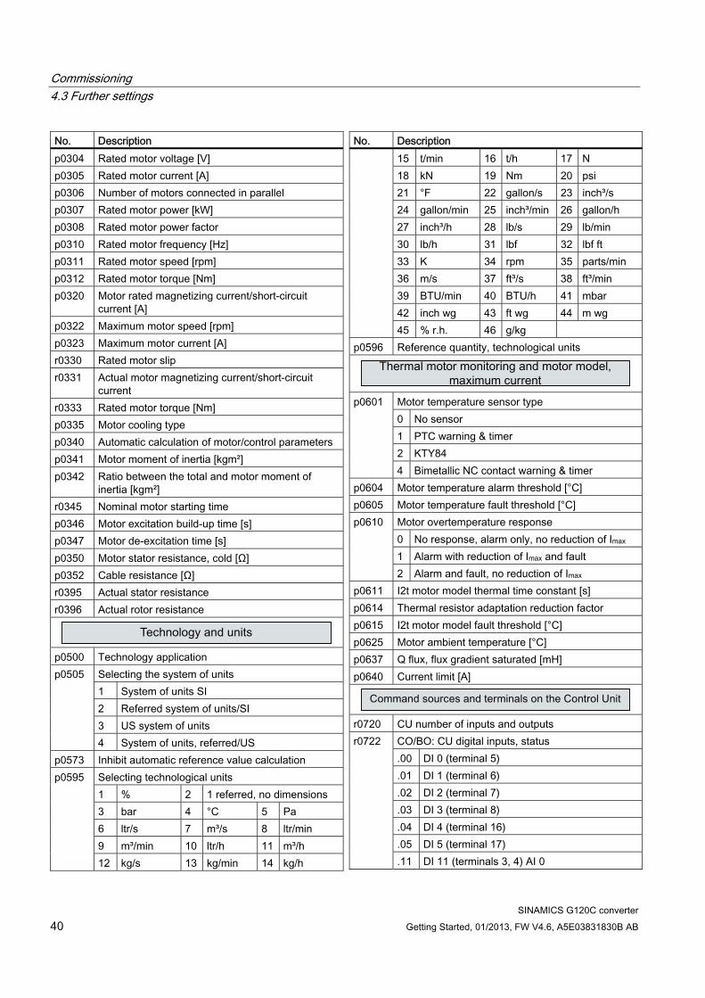
No. Description p0304 Rated motor voltage [V] p0305 Rated motor current [A] p0306 Number of motors connected in parallel p0307 Rated motor power [kW] p0308 Rated motor power factor p0310 Rated motor frequency [Hz] p0311 Rated motor speed [rpm] p0312 Rated motor torque [Nm] p0320 Motor rated magnetizing current/short-circuit
current [A] p0322 Maximum motor speed [rpm] p0323 Maximum motor current [A] r0330 Rated motor slip r0331 Actual motor magnetizing current/short-circuit
current r0333 Rated motor torque [Nm] p0335 Motor cooling type p0340 Automatic calculation of motor/control parameters p0341 Motor moment of inertia [kgm²] p0342 Ratio between the total and motor moment of
inertia [kgm²] r0345 Nominal motor starting time p0346 Motor excitation build-up time [s] p0347 Motor de-excitation time [s] p0350 Motor stator resistance, cold [Ω] p0352 Cable resistance [Ω] r0395 Actual stator resistance r0396 Actual rotor resistance
p0500 Technology application
Selecting the system of units 1 System of units SI 2 Referred system of units/SI 3 US system of units
p0505
4 System of units, referred/US p0573 Inhibit automatic reference value calculation
Selecting technological units 1 % 2 1 referred, no dimensions 3 bar 4 °C 5 Pa 6 ltr/s 7 m³/s 8 ltr/min 9 m³/min 10 ltr/h 11 m³/h
p0595
12 kg/s 13 kg/min 14 kg/h
No. Description 15 t/min 16 t/h 17 N 18 kN 19 Nm 20 psi 21 °F 22 gallon/s 23 inch³/s 24 gallon/min 25 inch³/min 26 gallon/h 27 inch³/h 28 lb/s 29 lb/min 30 lb/h 31 lbf 32 lbf ft 33 K 34 rpm 35 parts/min 36 m/s 37 ft³/s 38 ft³/min 39 BTU/min 40 BTU/h 41 mbar 42 inch wg 43 ft wg 44 m wg 45 % r.h. 46 g/kg
p0596 Reference quantity, technological units
Motor temperature sensor type 0 No sensor 1 PTC warning & timer 2 KTY84
p0601
4 Bimetallic NC contact warning & timer p0604 Motor temperature alarm threshold [°C] p0605 Motor temperature fault threshold [°C]
Motor overtemperature response 0 No response, alarm only, no reduction of Imax 1 Alarm with reduction of Imax and fault
p0610
2 Alarm and fault, no reduction of Imax p0611 I2t motor model thermal time constant [s] p0614 Thermal resistor adaptation reduction factor p0615 I2t motor model fault threshold [°C] p0625 Motor ambient temperature [°C] p0637 Q flux, flux gradient saturated [mH] p0640 Current limit [A]
r0720 CU number of inputs and outputs
CO/BO: CU digital inputs, status .00 DI 0 (terminal 5) .01 DI 1 (terminal 6) .02 DI 2 (terminal 7) .03 DI 3 (terminal 8) .04 DI 4 (terminal 16) .05 DI 5 (terminal 17)
r0722
.11 DI 11 (terminals 3, 4) AI 0
Commissioning 4.3 Further settings
SINAMICS G120C converter Getting Started, 01/2013, FW V4.6, A5E03831830B AB 41
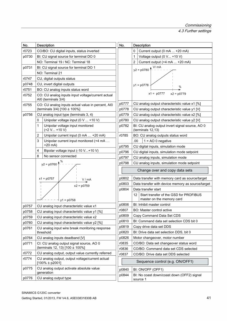
No. Description r0723 CO/BO: CU digital inputs, status inverted
BI: CU signal source for terminal DO 0 p0730 NO: Terminal 19 / NC: Terminal 18 BI: CU signal source for terminal DO 1 p0731 NO: Terminal 21
r0747 CU, digital outputs status p0748 CU, invert digital outputs r0751 BO: CU analog inputs status word r0752 CO: CU analog inputs input voltage/current actual
AI0 (terminals 3/4) r0755 CO: CU analog inputs actual value in percent, AI0
(terminals 3/4) [100 ≙ 100%] CU analog input type (terminals 3, 4) 0 Unipolar voltage input (0 V ... +10 V) 1 Unipolar voltage input monitored
(+2 V... +10 V) 2 Unipolar current input (0 mA … +20 mA) 3 Unipolar current input monitored (+4 mA …
+20 mA) 4 Bipolar voltage input (-10 V...+10 V)
p0756
8 No sensor connected
p0757 CU analog input characteristic value x1 p0758 CU analog input characteristic value y1 [%] p0759 CU analog input characteristic value x2 p0760 CU analog input characteristic value y2 [%] p0761 CU analog input wire break monitoring response
threshold p0764 CU analog inputs deadband [V] p0771 CI: CU analog output signal source, AO 0
(terminals 12, 13) [100 ≙ 100%] r0772 CU analog output, output value currently referred r0774 CU analog output, output voltage/current actual
[100% ≙ p2001] p0775 CU analog output activate absolute value
generation p0776 CU analog output type
No. Description 0 Current output (0 mA ... +20 mA) 1 Voltage output (0 V... +10 V) 2 Current output (+4 mA ... +20 mA)
p0777 CU analog output characteristic value x1 [%] p0778 CU analog output characteristic value y1 [V] p0779 CU analog output characteristic value x2 [%] p0780 CU analog output characteristic value y2 [V] p0782 BI: CU analog output invert signal source, AO 0
(terminals 12,13) BO: CU analog outputs status word r0785 .00 1 = AO 0 negative
p0795 CU digital inputs, simulation mode p0796 CU digital inputs, simulation mode setpoint p0797 CU analog inputs, simulation mode p0798 CU analog inputs, simulation mode setpoint
p0802 Data transfer with memory card as source/target p0803 Data transfer with device memory as source/target
Data transfer start p0804 12 Start transfer of the GSD for PROFIBUS
master on the memory card p0806 BI: Inhibit master control r0807 BO: Master control active p0809 Copy Command Data Set CDS p0810 BI: Command data set selection CDS bit 0 p0819 Copy drive data set DDS p0820 BI: Drive data set selection DDS, bit 0 p0826 Motor changeover, motor number r0835 CO/BO: Data set changeover status word r0836 CO/BO: Command data set CDS selected r0837 CO/BO: Drive data set DDS selected
p0840 BI: ON/OFF (OFF1) p0844 BI: No coast down/coast down (OFF2) signal
source 1
Commissioning 4.3 Further settings
SINAMICS G120C converter 42 Getting Started, 01/2013, FW V4.6, A5E03831830B AB
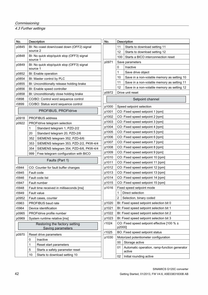
No. Description p0845 BI: No coast down/coast down (OFF2) signal
source 2 p0848 BI: No quick stop/quick stop (OFF3) signal
source 1 p0849 BI: No quick stop/quick stop (OFF3) signal
source 1 p0852 BI: Enable operation p0854 BI: Master control by PLC p0855 BI: Unconditionally release holding brake p0856 BI: Enable speed controller p0858 BI: Unconditionally close holding brake r0898 CO/BO: Control word sequence control r0899 CO/BO: Status word sequence control
p0918 PROFIBUS address
PROFIdrive telegram selection 1 Standard telegram 1, PZD-2/2 20 Standard telegram 20, PZD-2/6 352 SIEMENS telegram 352, PZD-6/6: 353 SIEMENS telegram 353, PZD-2/2, PKW-4/4 354 SIEMENS telegram 354, PZD-6/6, PKW-4/4
p0922
999 Free telegram configuration with BICO
r0944 CO: Counter for fault buffer changes r0945 Fault code r0946 Fault code list r0947 Fault number r0948 Fault time received in milliseconds [ms] r0949 Fault value p0952 Fault cases, counter r0963 PROFIBUS baud rate r0964 Device identification p0965 PROFIdrive profile number p0969 System runtime relative [ms]
Reset drive parameters 0 Inactive 1 Reset start parameters 5 Starts a safety parameter reset
p0970
10 Starts to download setting 10
No. Description 11 Starts to download setting 11 12 Starts to download setting 12 100 Starts a BICO interconnection reset Save parameters 0 Inactive 1 Save drive object 10 Save in a non-volatile memory as setting 10 11 Save in a non-volatile memory as setting 11
p0971
12 Save in a non-volatile memory as setting 12 p0972 Drive unit reset
p1000 Speed setpoint selection p1001 CO: Fixed speed setpoint 1 [rpm] p1002 CO: Fixed speed setpoint 2 [rpm] p1003 CO: Fixed speed setpoint 3 [rpm] p1004 CO: Fixed speed setpoint 4 [rpm] p1005 CO: Fixed speed setpoint 5 [rpm] p1006 CO: Fixed speed setpoint 6 [rpm] p1007 CO: Fixed speed setpoint 7 [rpm] p1008 CO: Fixed speed setpoint 8 [rpm] p1009 CO: Fixed speed setpoint 9 [rpm] p1010 CO: Fixed speed setpoint 10 [rpm] p1011 CO: Fixed speed setpoint 11 [rpm] p1012 CO: Fixed speed setpoint 12 [rpm] p1013 CO: Fixed speed setpoint 13 [rpm] p1014 CO: Fixed speed setpoint 14 [rpm] p1015 CO: Fixed speed setpoint 15 [rpm]
Fixed speed setpoint mode 1 Direct selection
p1016
2 Selection, binary coded p1020 BI: Fixed speed setpoint selection bit 0 p1021 BI: Fixed speed setpoint selection bit 1 p1022 BI: Fixed speed setpoint selection bit 2 p1023 BI: Fixed speed setpoint selection bit 3 r1024 CO: Fixed speed setpoint effective [100 % ≙
p2000] r1025 BO: Fixed speed setpoint status
Motorized potentiometer configuration 00 Storage active 01 Automatic operation, ramp-function generator
active
p1030
02 Initial rounding active

Commissioning 4.3 Further settings
SINAMICS G120C converter Getting Started, 01/2013, FW V4.6, A5E03831830B AB 43
No. Description 03 Storage in NVRAM active
p1035 BI: Motorized potentiometer setpoint raise p1036 BI: Motorized potentiometer setpoint lower p1037 Motorized potentiometer maximum speed [rpm] p1038 Motorized potentiometer minimum speed [rpm] p1040 Motorized potentiometer start value [rpm] p1043 BI: Motorized potentiometer, accept setting value p1044 CI: Motorized potentiometer setting value [100 % ≙
p2000] r1045 CO: Motorized potentiometer, setpoint in front of
the ramp-function generator [rpm] p1047 Motorized potentiometer ramp-up time [s] p1048 Motorized potentiometer ramp-down time [s] r1050 CO: Motorized potentiometer setpoint after the
ramp-function generator [100 % ≙ p2000] p1055 BI: Jog bit 0 p1056 BI: Jog bit 1 p1058 Jog 1 speed setpoint [rpm] p1059 Jog 2 speed setpoint [rpm] p1070 CI: Main setpoint [100 % ≙ p2000] p1071 CI: Main setpoint scaling [100 ≙ 100%] r1073 CO: Main setpoint effective [100 % ≙ p2000] p1075 CI: Supplementary setpoint [100 % ≙ p2000] p1076 CI: Supplementary setpoint scaling [100 ≙ 100%] r1077 CO: Supplementary setpoint effective
[100 % ≙ p2000] r1078 CO: Total setpoint effective [100 % ≙ p2000] p1080 Minimum speed [rpm] p1082 Maximum speed [rpm] p1083 CO:Speed limit in positive direction of rotation
[rpm] r1084 CO: Speed limit positive effective [100 % ≙ p2000] p1086 CO: Speed limit in negative direction of rotation
[rpm] r1087 CO: Speed limit negative effective [100 % ≙
p2000] p1091 Skip speed 1 [rpm] p1092 Skip speed 2 [rpm] p1101 Skip speed bandwidth [rpm] p1106 CI: Minimum speed signal source p1110 BI: Inhibit negative direction p1111 BI: Inhibit positive direction p1113 BI: Setpoint inversion
No. Description r1114 CO: Setpoint after the direction limiting [100 % ≙
p2000] r1119 CO: Ramp-function generator setpoint at the input
[100 % ≙ p2000]
p1120 Ramp-function generator ramp-up time [s] p1121 Ramp-function generator ramp-down time [s] p1130 Ramp-function generator initial rounding-off time
[s] p1131 Ramp-function generator final rounding-off time [s]
Ramp-function generator rounding-off type 0 Continuous smoothing
p1134
1 Discontinuous smoothing p1135 OFF3 ramp-down time [s] p1136 OFF3 initial rounding-off time [s] p1137 OFF3 final rounding-off time [s] p1138 CI: Acceleration ramp scaling [100 ≙ 100%] p1139 CI: Ramp down scaling [100 ≙ 100%] p1140 BI: Enable ramp-function generator p1141 BI: Continue ramp-function generator p1142 BI: Enable speed setpoint r1149 CO: Ramp-function generator acceleration [100 %
≙ p2007] r1170 CO: Speed controller setpoint sum
[100 % ≙ p2000] r1198 CO/BO: Control word, setpoint channel
Flying restart operating mode 0 Flying restart inactive 1 Flying restart always active (start in setpoint
direction)
p1200
4 Flying restart always active (start only in setpoint direction)
p1201 BI: Flying restart enable signal source p1202 Flying restart search current [100 % ≙ r0331]
Flying restart search rate factor [%] p1203 A higher value results in a longer search time.
Commissioning 4.3 Further settings
SINAMICS G120C converter 44 Getting Started, 01/2013, FW V4.6, A5E03831830B AB
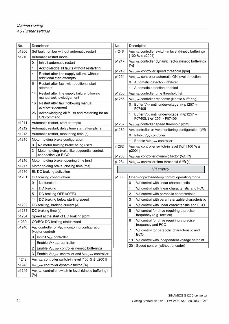
No. Description p1206 Set fault number without automatic restart
Automatic restart mode 0 Inhibit automatic restart 1 Acknowledge all faults without restarting 4 Restart after line supply failure, without
additional start attempts 6 Restart after fault with additional start
attempts 14 Restart after line supply failure following
manual acknowledgement 16 Restart after fault following manual
acknowledgement
p1210
26 Acknowledging all faults and restarting for an ON command
p1211 Automatic restart, start attempts p1212 Automatic restart, delay time start attempts [s] p1213 Automatic restart, monitoring time [s]
Motor holding brake configuration 0 No motor holding brake being used
p1215
3 Motor holding brake like sequential control, connection via BICO
p1216 Motor holding brake, opening time [ms] p1217 Motor holding brake, closing time [ms] p1230 BI: DC braking activation
DC braking configuration 0 No function 4 DC braking 5 DC braking OFF1/OFF3
p1231
14 DC braking below starting speed p1232 DC braking, braking current [A] p1233 DC braking time [s] p1234 Speed at the start of DC braking [rpm] r1239 CO/BO: DC braking status word
VDC controller or VDC monitoring configuration (vector control) 0 Inhibit VDC controller 1 Enable VDC_max controller 2 Enable VDC_min controller (kinetic buffering)
p1240
3 Enable VDC_min controller and VDC_max controller r1242 VDC_max controller switch-in level [100 % ≙ p2001] p1243 VDC_max controller dynamic factor [%] p1245 VDC_min controller switch-in level (kinetic buffering)
[%]
No. Description r1246 VDC_min controller switch-in level (kinetic buffering)
[100 % ≙ p2001] p1247 VDC_min controller dynamic factor (kinetic buffering)
[%] p1249 VDC_max controller speed threshold [rpm]
VDC_max controller automatic ON level detection 0 Automatic detection inhibited
p1254
1 Automatic detection enabled p1255 VDC_min controller time threshold [s]
VDC_min controller response (kinetic buffering) 0 Buffer VDC until undervoltage, n<p1257 →
F07405
p1256
1 Buffer VDC until undervoltage, n<p1257 → F07405, t>p1255 → F07406
p1257 VDC_min controller speed threshold [rpm] VDC controller or VDC monitoring configuration (V/f) 0 Inhibit VDC controller
p1280
1 Enable VDC_max controller r1282 VDC_max controller switch-in level (V/f) [100 % ≙
p2001] p1283 VDC_max controller dynamic factor (V/f) [%] p1284 VDC_max controller time threshold (U/f) [s]
Open-loop/closed-loop control operating mode 0 V/f control with linear characteristic 1 V/f control with linear characteristic and FCC 2 V/f control with parabolic characteristic 3 V/f control with parameterizable characteristic 4 V/f control with linear characteristic and ECO 5 V/f control for drive requiring a precise
frequency (e.g. textiles) 6 V/f control for drive requiring a precise
frequency and FCC 7 V/f control for parabolic characteristic and
ECO 19 V/f control with independent voltage setpoint
p1300
20 Speed control (without encoder)

Commissioning 4.3 Further settings
SINAMICS G120C converter Getting Started, 01/2013, FW V4.6, A5E03831830B AB 45
No. Description
V/f control configuration p1302 .03
Motor holding brake with constant stop frequency
p1310 Voltage boost permanent [100 % ≙ p0305] p1311 Voltage boost when accelerating [%] p1312 Voltage boost when starting [%] r1315 Voltage boost, total [100 % ≙ p2001]
p1320 V/f control programmable characteristic frequency
1 [Hz] p1321 V/f control programmable characteristic voltage 1
[V] p1322 Characteristic frequency 2 [Hz] p1323 Characteristic voltage 2 [V] p1324 Characteristic frequency 3 [Hz] p1325 Characteristic voltage 3 [V] p1326 Characteristic frequency 4 [Hz] p1327 Characteristic voltage 4 [V] p1330 CI: V/f control independent voltage setpoint
[100 % ≙ p2001] p1334 V/f control slip compensation starting frequency
[Hz] p1335 Slip compensation, scaling [100 % ≙ r0330] p1336 Slip compensation limit value [100 % ≙ r0330]
No. Description r1337 CO: Actual slip compensation [100 ≙ 100%] p1338 V/f mode resonance damping gain p1340 Imax frequency controller proportional gain r1343 CO: I_max controller frequency output
[100 % ≙ p2000] p1349 U/f mode resonance damping maximum frequency
[Hz] p1351 CO: Motor holding brake starting frequency
[100 ≙ 100%] p1352 CI: Motor holding brake starting frequency
[100 ≙ 100%]
r1438 CO: Speed controller speed setpoint
[100 % ≙ p2000] p1452 Speed controller speed actual value smoothing
time (SLVC) [ms] p1470 Speed controller encoderless operation P gain p1472 Speed controller sensorless operation integral time
[ms] p1475 CI: Speed controller torque setting value for motor
holding brake [100 % ≙ p2003] r1482 CO: Speed controller I torque output
[100 % ≙ p2003] r1493 CO: Moment of inertia, total p1496 Acceleration pre-control scaling [%] p1511 CI: Supplementary torque 1 [100 % ≙ p2003] r1516 CO: Supplementary torque and acceleration
torque [100 % ≙ p2003] p1520 CO: Torque limit upper [Nm] p1521 CO: Torque limit lower [Nm] p1522 CI: Torque limit upper [100 % ≙ p2003] p1523 CI: Torque limit lower [100 % ≙ p2003] p1524 CO: Torque limit upper/motoring scaling
[100 ≙ 100%] p1525 CO: Torque limit lower scaling [100 ≙ 100%] r1526 CO: Torque limit upper without offset
[100 % ≙ p2003] r1527 CO: Torque limit lower without offset
[100 % ≙ p2003] p1530 Power limit motoring [kW] p1531 Power limit regenerative [kW] r1538 CO: Upper effective torque limit [100 % ≙ p2003] r1539 CO: Lower effective torque limit [100 % ≙ p2003] r1547 CO: Torque limit for speed controller output
Commissioning 4.3 Further settings
SINAMICS G120C converter 46 Getting Started, 01/2013, FW V4.6, A5E03831830B AB
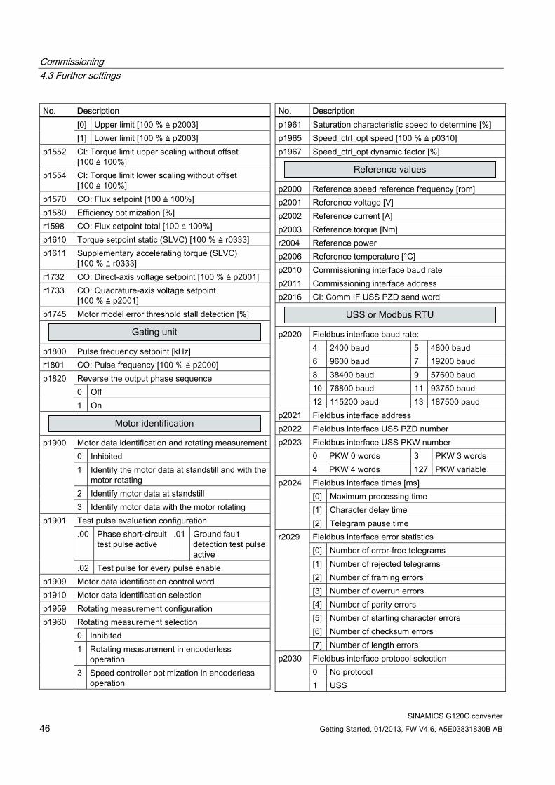
No. Description [0] Upper limit [100 % ≙ p2003] [1] Lower limit [100 % ≙ p2003]
p1552 CI: Torque limit upper scaling without offset [100 ≙ 100%]
p1554 CI: Torque limit lower scaling without offset [100 ≙ 100%]
p1570 CO: Flux setpoint [100 ≙ 100%] p1580 Efficiency optimization [%] r1598 CO: Flux setpoint total [100 ≙ 100%] p1610 Torque setpoint static (SLVC) [100 % ≙ r0333] p1611 Supplementary accelerating torque (SLVC)
[100 % ≙ r0333] r1732 CO: Direct-axis voltage setpoint [100 % ≙ p2001] r1733 CO: Quadrature-axis voltage setpoint
[100 % ≙ p2001] p1745 Motor model error threshold stall detection [%]
p1800 Pulse frequency setpoint [kHz] r1801 CO: Pulse frequency [100 % ≙ p2000]
Reverse the output phase sequence 0 Off
p1820
1 On
Motor data identification and rotating measurement0 Inhibited 1 Identify the motor data at standstill and with the
motor rotating 2 Identify motor data at standstill
p1900
3 Identify motor data with the motor rotating Test pulse evaluation configuration .00 Phase short-circuit
test pulse active .01 Ground fault
detection test pulse active
p1901
.02 Test pulse for every pulse enable p1909 Motor data identification control word p1910 Motor data identification selection p1959 Rotating measurement configuration
Rotating measurement selection 0 Inhibited 1 Rotating measurement in encoderless
operation
p1960
3 Speed controller optimization in encoderless operation
No. Description p1961 Saturation characteristic speed to determine [%] p1965 Speed_ctrl_opt speed [100 % ≙ p0310] p1967 Speed_ctrl_opt dynamic factor [%]
p2000 Reference speed reference frequency [rpm] p2001 Reference voltage [V] p2002 Reference current [A] p2003 Reference torque [Nm] r2004 Reference power p2006 Reference temperature [°C] p2010 Commissioning interface baud rate p2011 Commissioning interface address p2016 CI: Comm IF USS PZD send word
Fieldbus interface baud rate: 4 2400 baud 5 4800 baud 6 9600 baud 7 19200 baud 8 38400 baud 9 57600 baud 10 76800 baud 11 93750 baud
p2020
12 115200 baud 13 187500 baud p2021 Fieldbus interface address p2022 Fieldbus interface USS PZD number
Fieldbus interface USS PKW number 0 PKW 0 words 3 PKW 3 words
p2023
4 PKW 4 words 127 PKW variable Fieldbus interface times [ms] [0] Maximum processing time [1] Character delay time
p2024
[2] Telegram pause time Fieldbus interface error statistics [0] Number of error-free telegrams [1] Number of rejected telegrams [2] Number of framing errors [3] Number of overrun errors [4] Number of parity errors [5] Number of starting character errors [6] Number of checksum errors
r2029
[7] Number of length errors Fieldbus interface protocol selection 0 No protocol
p2030
1 USS

Commissioning 4.3 Further settings
SINAMICS G120C converter Getting Started, 01/2013, FW V4.6, A5E03831830B AB 47
No. Description 2 MODBUS 3 PROFIBUS 4 CAN Master control, control word effective .00 ON / OFF1 .01 OFF2 inactive .02 OFF3 inactive .03 Enable operation .04 Enable ramp-function generator .05 Start ramp-function generator .06 Enable speed setpoint .07 Acknowledge fault .08 Jog bit 0 .09 Jog bit 1
r2032
.10 Master control by PLC PROFIdrive STW1.10 = 0 mode 0 Freeze setpoints and further process sign-of-
life 1 Freeze setpoints and sign-of-life
p2037
2 Setpoints are not frozen PROFIdrive STW/ZSW interface mode 0 SINAMICS
p2038
2 VIK-NAMUR p2040 Fieldbus interface monitoring time [ms]
PROFIBUS ID Number 0 SINAMICS
p2042
2 VIK-NAMUR BO: PROFIdrive PZD state .00 Setpoint failure
r2043
.02 Fieldbus operational p2044 PROFIdrive fault delay [s] p2047 PROFIBUS additional monitoring time [ms]
CO: PROFIdrive PZD receive word r2050 [0] PZD 1 … [7] PZD 8 CI: PROFIdrive PZD send word p2051 [0] PZD 1 … [7] PZD 8 PROFIdrive diagnostics send PZD word r2053 [0] PZD 1 … [7] PZD 8 PROFIBUS status 0 Off
r2054
1 No connection (search for baud rate)
No. Description 2 Connection OK (baud rate found) 3 Cyclic connection with master (data exchange) 4 Cyclic data OK PROFIBUS diagnosis standard [0] Master bus address [1] Master input total length bytes
r2055
[2] Master output total length bytes r2057 PROFIBUS address switch diagnostics
CO: IF1 PROFIdrive PZD receive double word r2060 [0] PZD 1 + 2 … [10] PZD 11 + 12 CI: IF1 PROFIdrive PZD send double word r2061 [0] PZD 1 + 2 … [10] PZD 11 + 12 IF1 PROFIdrive diagnostics PZD send double word
r2063
[0] PZD 1 + 2 … [10] PZD 11 + 12 IF1 PZD maximum interconnected [0] Receiving
r2067
[1] Sending PROFIdrive diagnostics bus address PZD receive r2074 [0] PZD 1 … [7] PZD 8 PROFIdrive diagnostics telegram offset PZD receive
r2075
[0] PZD 1 … [7] PZD 8 PROFIdrive diagnostics telegram offset PZD send r2076 [0] PZD 1 … [7] PZD 8
r2077 PROFIBUS diagnostics peer-to-peer data transfer addresses PROFIdrive PZD telegram selection extended p2079 See p0922 BI: Binector-connector converter, status word 1 p2080 The individual bits are combined to form status word 1.
p2088 Binector-connector converter, invert status word CO: Send binector-connector converter status word [0] Status word 1 [1] Status word 2 [2] Free status word 3 [3] Free status word 4
r2089
[4] Free status word 5 r2090 BO: PROFIdrive PZD1 receive bit-serial r2091 BO: PROFIdrive PZD2 receive bit-serial r2092 BO: PROFIdrive PZD3 receive bit-serial

Commissioning 4.3 Further settings
SINAMICS G120C converter 48 Getting Started, 01/2013, FW V4.6, A5E03831830B AB
No. Description r2093 BO: PROFIdrive PZD4 receive bit-serial r2094 BO: Connector-binector converter binector output r2095 BO: Connector-binector converter binector output p2098 Invert connector-binector converter binector output p2099 CI: Connector-binector converter signal source
p2100 Setting the fault number for fault response
Setting the fault response 0 None 1 OFF1 2 OFF2 3 OFF3
p2101
5 STOP2 6 DC braking p2103 BI: 1. Acknowledge faults p2104 BI: 2. Acknowledge faults p2106 BI: External fault 1 r2110 Alarm number p2111 Alarm counter p2112 BI: External alarm 1 r2122 Alarm code r2123 Alarm time received [ms] r2124 Alarm value r2125 Alarm time removed [ms] p2126 Setting fault number for acknowledge mode p2127 Sets acknowledgement mode p2128 Selecting fault/alarm code for trigger r2129 CO/BO: Trigger word for faults and alarms r2130 Fault time received in days r2131 CO: Actual fault code r2132 CO: Actual alarm code r2133 Fault value for float values r2134 Alarm value for float values r2135 CO/BO: Status word, faults/alarms 2 r2136 Fault time removed in days r2138 CO/BO: Control word, faults/alarms r2139 CO/BO: Status word, faults/alarms 1 r2169 CO: Actual speed smoothed signals r2197 CO/BO: Status word monitoring functions 1 r2198 CO/BO: Status word monitoring 2 r2199 CO/BO: Status word monitoring 3
p2200 BI: Technology controller enable p2201 CO: Techn. controller fixed value 1 [100 ≙ 100%]
No. Description p2202 CO: Techn. controller fixed value 2 [100 ≙ 100%] p2203 CO: Techn. controller fixed value 3 [100 ≙ 100%] p2204 CO: Techn. controller fixed value 4 [100 ≙ 100%] p2205 CO: Techn. controller fixed value 5 [100 ≙ 100%] p2206 CO: Techn. controller fixed value 6 [100 ≙ 100%] p2207 CO: Techn. controller fixed value 7 [100 ≙ 100%] p2208 CO: Techn. controller fixed value 8 [100 ≙ 100%] p2209 CO: Techn. controller fixed value 9 [100 ≙ 100%] p2210 CO: Techn. controller fixed value 10 [100 ≙ 100%] p2211 CO: Techn. controller fixed value 11 [100 ≙ 100%] p2212 CO: Techn. controller fixed value 12 [100 ≙ 100%] p2213 CO: Techn. controller fixed value 13 [100 ≙ 100%] p2214 CO: Techn. controller fixed value 14 [100 ≙ 100%] p2215 CO: Techn. controller fixed value 15 [100 ≙ 100%]
Techn. controller fixed value selection method 0 Fixed value selection direct
p2216
1 Fixed value selection binary p2220 BI: Techn. controller fixed value selection bit 0 p2221 BI: Techn. controller fixed value selection bit 1 p2222 BI: Techn. controller fixed value selection bit 2 p2223 BI: Techn. controller fixed value selection bit 3 r2224 CO: Techn. controller fixed value active [100 ≙
100%] r2225 CO/BO: Techn. controller fixed value selection
status word r2229 Techn. controller number currently
Techn. controller motorized potentiometer configuration .00 Storage active .02 Initial rounding active .03 Non-volatile data save active for p2230.0 = 1
p2230
.04 Ramp-function generator always active r2231 Techn. controller motorized potentiometer setpoint
memory p2235 BI: Techn. controller motorized potentiometer
setpoint up p2236 BI: Techn. controller motorized potentiometer
setpoint down p2237 Techn. controller motorized potentiometer
maximum value [%] p2238 Techn. controller motorized potentiometer
minimum value [%] p2240 Techn. controller motorized potentiometer start
value [%]

Commissioning 4.3 Further settings
SINAMICS G120C converter Getting Started, 01/2013, FW V4.6, A5E03831830B AB 49
No. Description r2245 CO: Techn. controller motorized potentiometer
setpoint before RFG [100 ≙ 100%] p2247 Techn. controller motorized potentiometer ramp-up
time [s] p2248 Techn. controller motorized potentiometer ramp-
down time [s] r2250 CO: Techn. controller motorized potentiometer
setpoint after RFG [100 ≙ 100%] Techn. controller mode 0 Techn. controller as main speed setpoint
p2251
1 Techn. controller as additional speed setpoint p2253 CI: Techn. controller setpoint 1 [100 ≙ 100%] p2254 CI: Techn. controller setpoint 2 [100 ≙ 100%] p2255 Techn. controller setpoint 1 scaling [100 ≙ 100%] p2256 Techn. controller setpoint 2 scaling [100 ≙ 100%] p2257 Techn. controller ramp-up time [s] p2258 Techn. controller ramp-down time [s] r2260 CO: Techn. controller setpoint after ramp function
generator [100 ≙ 100%] p2261 Techn. controller setpoint filter time constant [s]
Techn. controller type 0 D component in the actual value signal
p2263
1 D component in the fault signal p2264 CI: Techn. controller actual value [100 ≙ 100%] p2265 Techn. controller actual value filter time constant
[s] r2266 CO: Techn. controller actual value after filter [100
≙ 100%] p2267 Techn. controller upper limit actual value [100 ≙
100%] p2268 Techn. controller lower limit actual value [100 ≙
100%] p2269 Techn. controller gain actual value [%]
Techn. controller actual value function selection 0 No function 1 √x
p2270
2 x² 3 x³ Techn. controller actual value inversion (sensor type) 0 No inversion
p2271
1 Inversion of the technology controller actual value signal
r2272 CO: Techn. controller actual value scaled [100 ≙ 100%]
r2273 CO: Techn. controller error [100 ≙ 100%]
No. Description p2274 Techn. controller actual differentiation time
constant [s] p2280 Techn. controller proportional gain p2285 Techn. controller integral time [s] p2286 BI: Hold techn. controller integrator p2289 CI: Techn. controller pre-control signal [100 ≙
100%] p2291 CO: Techn. controller maximum limit [100 ≙ 100%] p2292 CO: Techn. controller minimum limit [100 ≙ 100%] p2293 Techn. controller ramp-up/ramp-down time [s] r2294 CO: Techn. controller output signal [100 ≙ 100%] p2295 CO: Techn. controller output scaling [100 ≙ 100%] p2296 CI: Techn. controller output scaling [100 ≙ 100%] p2297 CI: Techn. controller maximum limit signal source
[100 ≙ 100%] p2298 CI: Techn. controller minimum limit signal source
[100 ≙ 100%] p2299 CI: Techn. controller limit offset [100 ≙ 100%] p2302 Techn. controller output signal start value [%]
Techn. controller fault signal inversion 0 No inversion
p2306
1 Inversion of the techn. controller fault signal r2344 CO: Techn. controller last speed setpoint
(smoothed) [100 ≙ 100%] Techn. controller fault response 0 Function inhibited 1 For a fault: change over to r2344 (or p2302)
p2345
2 For a fault: Change over to p2215 r2349 CO/BO: Techn. controller status word p2900 CO: Fixed value 1 [100 ≙ 100%] p2901 CO: Fixed value 2 [100 ≙ 100%] r2902 CO: Fixed values [100 ≙ 100%] p2930 CO: Fixed value M [Nm]
r3113 CO/BO: NAMUR message bit bar
Change safety message type 0: Safety messages are not reparameterized
p3117
1: Safety messages are reparameterized
p3320 Fluid flow machine P = f(n), Y coordinate: P flow
1%, point 1
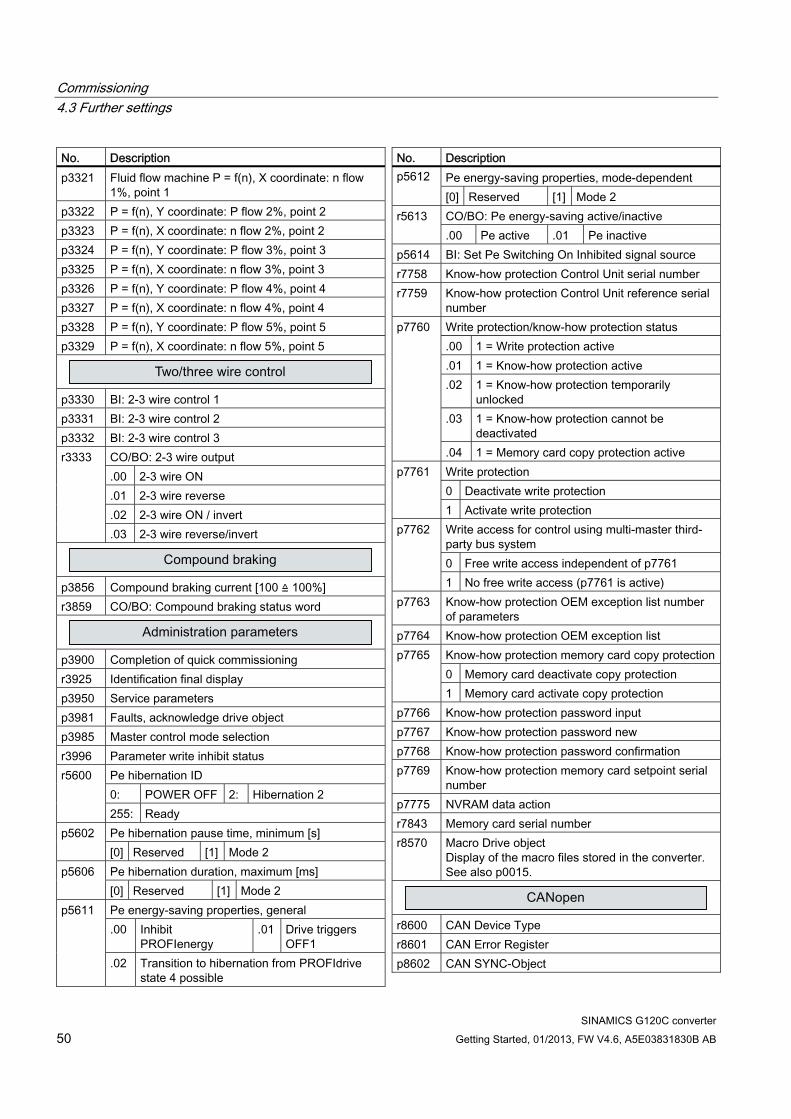
Commissioning 4.3 Further settings
SINAMICS G120C converter 50 Getting Started, 01/2013, FW V4.6, A5E03831830B AB
No. Description p3321 Fluid flow machine P = f(n), X coordinate: n flow
1%, point 1 p3322 P = f(n), Y coordinate: P flow 2%, point 2 p3323 P = f(n), X coordinate: n flow 2%, point 2 p3324 P = f(n), Y coordinate: P flow 3%, point 3 p3325 P = f(n), X coordinate: n flow 3%, point 3 p3326 P = f(n), Y coordinate: P flow 4%, point 4 p3327 P = f(n), X coordinate: n flow 4%, point 4 p3328 P = f(n), Y coordinate: P flow 5%, point 5 p3329 P = f(n), X coordinate: n flow 5%, point 5
p3330 BI: 2-3 wire control 1 p3331 BI: 2-3 wire control 2 p3332 BI: 2-3 wire control 3
CO/BO: 2-3 wire output .00 2-3 wire ON .01 2-3 wire reverse .02 2-3 wire ON / invert
r3333
.03 2-3 wire reverse/invert
p3856 Compound braking current [100 ≙ 100%] r3859 CO/BO: Compound braking status word
p3900 Completion of quick commissioning r3925 Identification final display p3950 Service parameters p3981 Faults, acknowledge drive object p3985 Master control mode selection r3996 Parameter write inhibit status
Pe hibernation ID 0: POWER OFF 2: Hibernation 2
r5600
255: Ready Pe hibernation pause time, minimum [s] p5602 [0] Reserved [1] Mode 2 Pe hibernation duration, maximum [ms] p5606 [0] Reserved [1] Mode 2 Pe energy-saving properties, general .00 Inhibit
PROFIenergy .01 Drive triggers
OFF1
p5611
.02 Transition to hibernation from PROFIdrive state 4 possible
No. Description Pe energy-saving properties, mode-dependent p5612 [0] Reserved [1] Mode 2 CO/BO: Pe energy-saving active/inactive r5613 .00 Pe active .01 Pe inactive
p5614 BI: Set Pe Switching On Inhibited signal source r7758 Know-how protection Control Unit serial number r7759 Know-how protection Control Unit reference serial
number Write protection/know-how protection status .00 1 = Write protection active .01 1 = Know-how protection active .02 1 = Know-how protection temporarily
unlocked .03 1 = Know-how protection cannot be
deactivated
p7760
.04 1 = Memory card copy protection active Write protection 0 Deactivate write protection
p7761
1 Activate write protection Write access for control using multi-master third-party bus system 0 Free write access independent of p7761
p7762
1 No free write access (p7761 is active) p7763 Know-how protection OEM exception list number
of parameters p7764 Know-how protection OEM exception list
Know-how protection memory card copy protection0 Memory card deactivate copy protection
p7765
1 Memory card activate copy protection p7766 Know-how protection password input p7767 Know-how protection password new p7768 Know-how protection password confirmation p7769 Know-how protection memory card setpoint serial
number p7775 NVRAM data action r7843 Memory card serial number r8570 Macro Drive object
Display of the macro files stored in the converter. See also p0015.
r8600 CAN Device Type r8601 CAN Error Register p8602 CAN SYNC-Object

Commissioning 4.3 Further settings
SINAMICS G120C converter Getting Started, 01/2013, FW V4.6, A5E03831830B AB 51
No. Description p8603 CAN COB-ID Emergency Message [hex] p8604 CAN Node Guarding p8606 CAN Producer Heartbeat Time [ms] r8607 CAN Identity Object p8608 CAN Clear Bus Off Error p8609 CAN Error Behavior r8610 CAN First Server SDO p8611 CAN Pre-defined Error Field [hex] p8620 CAN Node-ID r8621 CAN Node-ID effective
CAN bit rate [kBit/s] 0 1000 1 800 2 500 3 250 4 125 5 50
p8622
6 20 7 10 p8623 CAN Bit Timing selection [hex] p8630 CAN virtual objects
CAN Abort Connection Option Code 0 No response 1 OFF1
p8641
2 OFF2 3 OFF3 r8680 CAN Diagnosis Hardware p8684 CAN NMT state after booting p8685 CAN NMT state p8699 CAN RPDO monitoring time [ms] p8700 CAN Receive PDO 1 [hex] p8701 CAN Receive PDO 2 [hex] p8702 CAN Receive PDO 3 [hex] p8703 CAN Receive PDO 4 [hex] p8704 CAN Receive PDO 5 [hex] p8705 CAN Receive PDO 6 [hex] p8706 CAN Receive PDO 7 [hex] p8707 CAN Receive PDO 8 [hex] p8710 CAN Receive Mapping for RPDO 1 [hex] p8711 CAN Receive Mapping for RPDO 2 [hex] p8712 CAN Receive Mapping for RPDO 3 [hex] p8713 CAN Receive Mapping for RPDO 4 [hex] p8714 CAN Receive Mapping for RPDO 5 [hex] p8715 CAN Receive Mapping for RPDO 6 [hex] p8716 CAN Receive Mapping for RPDO 7 [hex] p8717 CAN Receive Mapping for RPDO 8 [hex] p8720 CAN Transmit PDO 1 [hex] p8721 CAN Transmit PDO 2 [hex] p8722 CAN Transmit PDO 3 [hex]
No. Description p8723 CAN Transmit PDO 4 [hex] p8724 CAN Transmit PDO 5 [hex] p8725 CAN Transmit PDO 6 [hex] p8726 CAN Transmit PDO 7 [hex] p8727 CAN Transmit PDO 8 [hex] p8730 CAN Transmit Mapping for TPDO 1 [hex] p8731 CAN Transmit Mapping for TPDO 2 [hex] p8732 CAN Transmit Mapping for TPDO 3 [hex] p8733 CAN Transmit Mapping for TPDO 4 [hex] p8734 CAN Transmit Mapping for TPDO 5 [hex] p8735 CAN Transmit Mapping for TPDO 6 [hex] p8736 CAN Transmit Mapping for TPDO 7 [hex] p8737 CAN Transmit Mapping for TPDO 8 [hex] p8741 CAN PDO configuration acknowledgment
CAN PDO Mapping Configuration 1: Predefined connection set
p8744
2: Free PDO mapping r8750 CAN mapped receive objects 16 bit r8751 CAN mapped receive objects 16 bit r8784 CO: CAN status word p8785 BI: CAN status word bit 8 p8786 BI: CAN status word bit 14 p8787 BI: CAN status word bit 15 p8790 CAN control word - auto interconnection r8795 CAN control word r8797 CAN Target Torque
r8820 Identification and Maintenance 0 p8829 CBE20 Remote Controller number r8909 PN Device ID p8920 PN Name of station p8921 PN IP Address of Station p8922 PN Default Gateway of Station p8923 PN Subnet Mask of Station
PN interfaces configuration 0: No function 1: Activate the configuration 2: Activate the configuration and save
p8925
3: Delete configuration PN Remote Controller number p8929 0: Automation or Safety
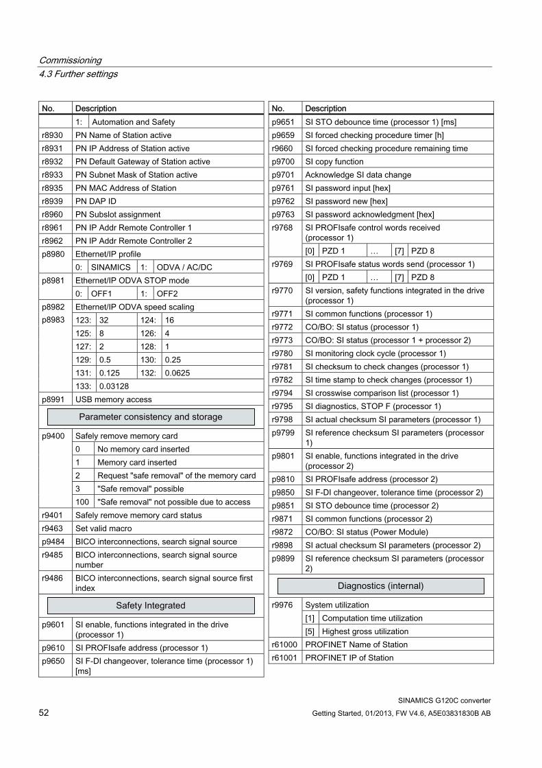
Commissioning 4.3 Further settings
SINAMICS G120C converter 52 Getting Started, 01/2013, FW V4.6, A5E03831830B AB
No. Description 1: Automation and Safety
r8930 PN Name of Station active r8931 PN IP Address of Station active r8932 PN Default Gateway of Station active r8933 PN Subnet Mask of Station active r8935 PN MAC Address of Station r8939 PN DAP ID r8960 PN Subslot assignment r8961 PN IP Addr Remote Controller 1 r8962 PN IP Addr Remote Controller 2
Ethernet/IP profile p8980 0: SINAMICS 1: ODVA / AC/DC Ethernet/IP ODVA STOP mode p8981 0: OFF1 1: OFF2 Ethernet/IP ODVA speed scaling 123: 32 124: 16 125: 8 126: 4 127: 2 128: 1 129: 0.5 130: 0.25 131: 0.125 132: 0.0625
p8982 p8983
133: 0.03128 p8991 USB memory access
Safely remove memory card 0 No memory card inserted 1 Memory card inserted 2 Request "safe removal" of the memory card 3 "Safe removal" possible
p9400
100 "Safe removal" not possible due to access r9401 Safely remove memory card status r9463 Set valid macro p9484 BICO interconnections, search signal source r9485 BICO interconnections, search signal source
number r9486 BICO interconnections, search signal source first
index
p9601 SI enable, functions integrated in the drive
(processor 1) p9610 SI PROFIsafe address (processor 1) p9650 SI F-DI changeover, tolerance time (processor 1)
[ms]
No. Description p9651 SI STO debounce time (processor 1) [ms] p9659 SI forced checking procedure timer [h] r9660 SI forced checking procedure remaining time p9700 SI copy function p9701 Acknowledge SI data change p9761 SI password input [hex] p9762 SI password new [hex] p9763 SI password acknowledgment [hex]
SI PROFIsafe control words received (processor 1)
r9768
[0] PZD 1 … [7] PZD 8 SI PROFIsafe status words send (processor 1) r9769 [0] PZD 1 … [7] PZD 8
r9770 SI version, safety functions integrated in the drive (processor 1)
r9771 SI common functions (processor 1) r9772 CO/BO: SI status (processor 1) r9773 CO/BO: SI status (processor 1 + processor 2) r9780 SI monitoring clock cycle (processor 1) r9781 SI checksum to check changes (processor 1) r9782 SI time stamp to check changes (processor 1) r9794 SI crosswise comparison list (processor 1) r9795 SI diagnostics, STOP F (processor 1) r9798 SI actual checksum SI parameters (processor 1) p9799 SI reference checksum SI parameters (processor
1) p9801 SI enable, functions integrated in the drive
(processor 2) p9810 SI PROFIsafe address (processor 2) p9850 SI F-DI changeover, tolerance time (processor 2) p9851 SI STO debounce time (processor 2) r9871 SI common functions (processor 2) r9872 CO/BO: SI status (Power Module) r9898 SI actual checksum SI parameters (processor 2) p9899 SI reference checksum SI parameters (processor
2)
System utilization [1] Computation time utilization
r9976
[5] Highest gross utilization r61000 PROFINET Name of Station r61001 PROFINET IP of Station
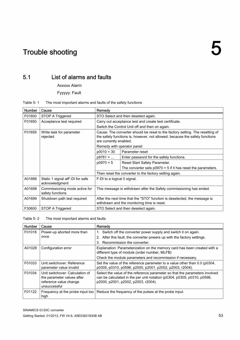
SINAMICS G120C converter Getting Started, 01/2013, FW V4.6, A5E03831830B AB 53
Trouble shooting 55.1 List of alarms and faults
Axxxxx Alarm
Fyyyyy: Fault
Table 5- 1 The most important alarms and faults of the safety functions
Number Cause Remedy F01600 STOP A Triggered STO Select and then deselect again. F01650 Acceptance test required Carry out acceptance test and create test certificate.
Switch the Control Unit off and then on again. Cause: The converter should be reset to the factory setting. The resetting of the safety functions is, however, not allowed, because the safety functions are currently enabled. Remedy with operator panel: p0010 = 30 Parameter reset p9761 = … Enter password for the safety functions. p0970 = 5 Reset Start Safety Parameter.
The converter sets p0970 = 5 if it has reset the parameters.
F01659 Write task for parameter rejected
Then reset the converter to the factory setting again. A01666 Static 1 signal atF-DI for safe
acknowledgment F-DI to a logical 0 signal.
A01698 Commissioning mode active for safety functions
This message is withdrawn after the Safety commissioning has ended.
A01699 Shutdown path test required After the next time that the "STO" function is deselected, the message is withdrawn and the monitoring time is reset.
F30600 STOP A Triggered STO Select and then deselect again.
Table 5- 2 The most important alarms and faults
Number Cause Remedy F01018 Power-up aborted more than
once 1. Switch off the converter power supply and switch it on again. 2. After this fault, the converter powers up with the factory settings. 3. Recommission the converter.
A01028 Configuration error Explanation: Parameterization on the memory card has been created with a different type of module (order number, MLFB) Check the module parameters and recommission if necessary.
F01033 Unit switchover: Reference parameter value invalid
Set the value of the reference parameter to a value other than 0.0 (p0304, p0305, p0310, p0596, p2000, p2001, p2002, p2003, r2004).
F01034 Unit switchover: Calculation of the parameter values after reference value change unsuccessful
Select the value of the reference parameter so that the parameters involved can be calculated in the per unit notation (p0304, p0305, p0310, p0596, p2000, p2001, p2002, p2003, r2004).
F01122 Frequency at the probe input too high
Reduce the frequency of the pulses at the probe input.

Trouble shooting 5.1 List of alarms and faults
SINAMICS G120C converter 54 Getting Started, 01/2013, FW V4.6, A5E03831830B AB
Number Cause Remedy A01590 Motor maintenance interval
lapsed Carry out the maintenance.
A01900 PROFIBUS: Configuration telegram faulty
Explanation: A PROFIBUS master is attempting to establish a connection with a faulty configuration telegram. Check the bus configuration on the master and slave side.
A01910 F01910
Fieldbus SS setpoint timeout The alarm is generated when p2040 ≠ 0 ms and one of the following causes is present: The bus connection is interrupted The MODBUS master is switched off Communications error (CRC, parity bit, logical error) An excessively low value for the fieldbus monitoring time (p2040)
A01920 PROFIBUS: Cyclic connection interrupt
Explanation: The cyclic connection to PROFIBUS master is interrupted. Establish the PROFIBUS connection and activate the PROFIBUS master with cyclic operation.
F03505 Analog input, wire break Check the connection to the signal source for interrupts. Check the level of the signal supplied. The input current measured by the analog input can be read out in r0752.
A03520 Temperature sensor fault Check that the sensor is connected correctly. A05000 A05001 A05002 A05004 A05006
Power Module overtemperature Check the following: - Is the ambient temperature within the defined limit values? - Are the load conditions and duty cycle configured accordingly? - Has the cooling failed?
F06310 Supply voltage (p0210) incorrectly parameterized
Check the parameterized supply voltage and if required change (p0210). Check the line voltage.
F07011 Motor overtemperature Reduce the motor load. Check ambient temperature. Check sensor's wiring and connection.
A07012 I2t Motor Module overtemperature
Check and if necessary reduce the motor load. Check the motor's ambient temperature. Check thermal time constant p0611. Check overtemperature fault threshold p0605.
A07015 Motor temperature sensor alarm Check that the sensor is connected correctly. Check the parameter assignment (p0601).
F07016 Motor temperature sensor fault Make sure that the sensor is connected correctly. Check the parameterization (p0601).
F07086 F07088
Unit switchover: Parameter limit violation
Check the adapted parameter values and if required correct.
F07320 Automatic restart aborted Increase the number of restart attempts (p1211). The current number of start attempts is shown in r1214. Increase the wait time in p1212 and/or monitoring time in p1213. Create ON command (p0840). Increase the monitoring time of the power unit or switch off (p0857). Reduce the wait time for resetting the fault counter p1213[1] so that fewer faults are registered in the time interval.
A07321 Automatic restart active Explanation: The automatic restart (AR) is active. During voltage recovery and/or when remedying the causes of pending faults, the drive is automatically switched back on.

Trouble shooting 5.1 List of alarms and faults
SINAMICS G120C converter Getting Started, 01/2013, FW V4.6, A5E03831830B AB 55
Number Cause Remedy F07330 Search current measured too
low Increase search current (P1202), check motor connection.
A07400 VDC_max controller active If the controller is not to intervene: Increase the ramp-down times. Deactivate the VDC_max controller (p1240 = 0 for vector control, p1280 = 0 for V/f control).
A07409 V/f control current limiting controller active
The alarm automatically disappears after one of the following measures: Increase the current limit (p0640). Reduce load. Increase the ramp-up time to the speed setpoint.
F07426 Technology controller actual value limited
Adapt the limits to the signal level (p2267, p2268). Check the actual value scaling (p2264).
F07801 Motor overcurrent Check current limits (p0640). U/f control: Check the current limiting controller (p1340 … p1346). Increase acceleration ramp (p1120) or reduce load. Check motor and motor cables for short circuit and ground fault. Check motor for star-delta connection and rating plate parameterization. Check power unit / motor combination. Select flying restart function (p1200) if switched to rotating motor.
A07805 Drive: Power unit overload I2t Reduce the continuous load. Adapt the load cycle. Check the assignment of rated currents of the motor and power unit.
F07807 Short circuit detected Check the converter connection on the motor side for any phase-phase short-circuit. Rule out that line and motor cables have been interchanged.
A07850 External alarm 1 The signal for "external alarm 1" has been triggered. Parameter p2112 defines the signal source of the external alarm. Remedy: Rectify the cause of this alarm.
F07860 External fault 1 Remove the external causes for this fault. F07900 Motor blocked Make sure that the motor can rotate freely.
Check the torque limit: r1538 for a positive direction of rotation; r1539 for a negative direction of rotation.
F07901 Motor overspeed Activate precontrol of the speed limiting controller (p1401 bit 7 = 1). F07902 Motor stalled Check whether the motor data has been parameterized correctly and perform
motor identification. Check the current limits (p0640, r0067, r0289). If the current limits are too low, the drive cannot be magnetized. Check whether motor cables are disconnected during operation.
A07903 Motor speed deviation Increase p2163 and/or p2166. Increase the torque, current and power limits.
A07910 Motor overtemperature Check the motor load. Check the motor's ambient temperature. Check the KTY84 sensor.
A07920 Torque/speed too low A07921 Torque/speed too high A07922 Torque/speed out of tolerance
The torque deviates from the torque/speed envelope curve. Check the connection between the motor and the load. Adapt the parameterization corresponding to the load.
F07923 Torque/speed too low F07924 Torque/speed too high
Check the connection between the motor and the load. Adapt the parameterization corresponding to the load.
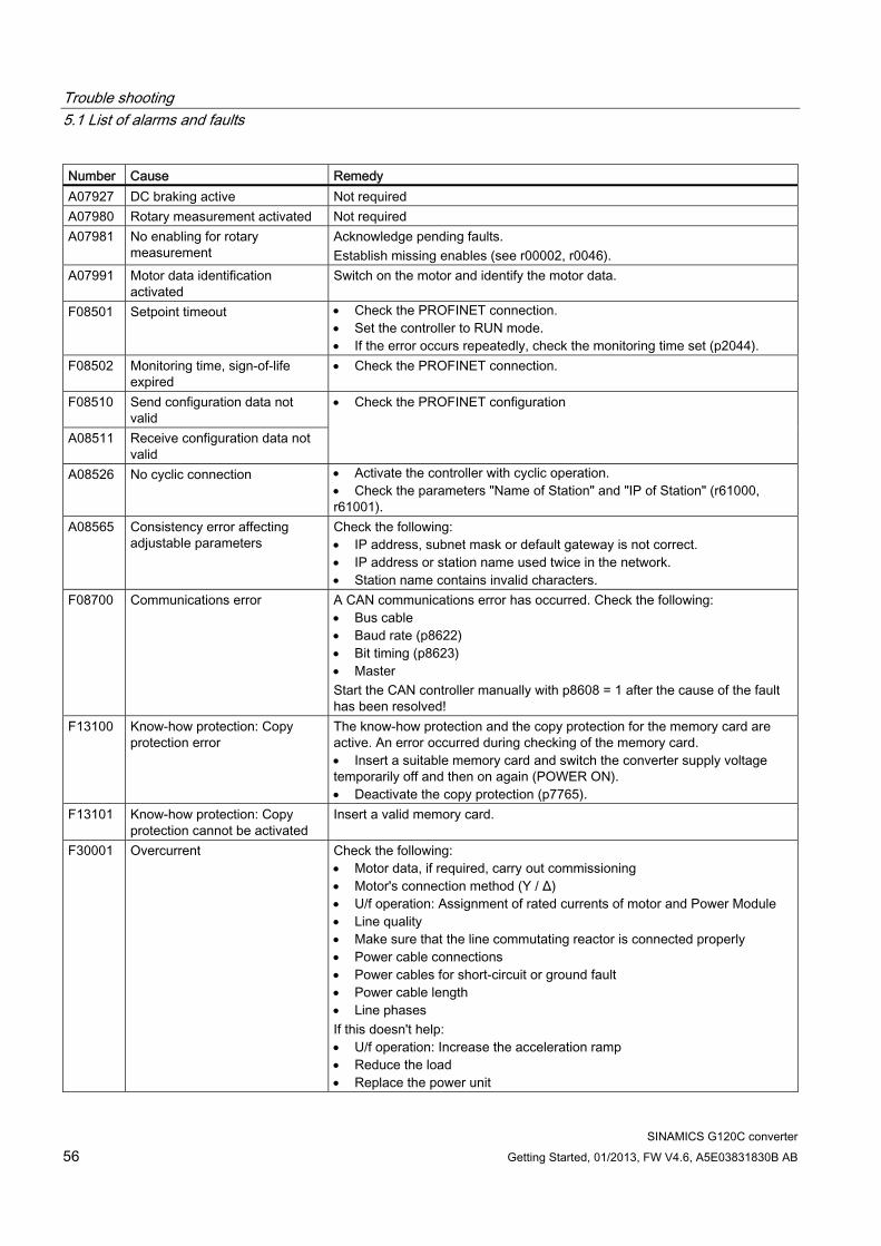
Trouble shooting 5.1 List of alarms and faults
SINAMICS G120C converter 56 Getting Started, 01/2013, FW V4.6, A5E03831830B AB
Number Cause Remedy A07927 DC braking active Not required A07980 Rotary measurement activated Not required A07981 No enabling for rotary
measurement Acknowledge pending faults. Establish missing enables (see r00002, r0046).
A07991 Motor data identification activated
Switch on the motor and identify the motor data.
F08501 Setpoint timeout Check the PROFINET connection. Set the controller to RUN mode. If the error occurs repeatedly, check the monitoring time set (p2044).
F08502 Monitoring time, sign-of-life expired
Check the PROFINET connection.
F08510 Send configuration data not valid
A08511 Receive configuration data not valid
Check the PROFINET configuration
A08526 No cyclic connection Activate the controller with cyclic operation. Check the parameters "Name of Station" and "IP of Station" (r61000, r61001).
A08565 Consistency error affecting adjustable parameters
Check the following: IP address, subnet mask or default gateway is not correct. IP address or station name used twice in the network. Station name contains invalid characters.
F08700 Communications error A CAN communications error has occurred. Check the following: Bus cable Baud rate (p8622) Bit timing (p8623) Master Start the CAN controller manually with p8608 = 1 after the cause of the fault has been resolved!
F13100 Know-how protection: Copy protection error
The know-how protection and the copy protection for the memory card are active. An error occurred during checking of the memory card. Insert a suitable memory card and switch the converter supply voltage temporarily off and then on again (POWER ON). Deactivate the copy protection (p7765).
F13101 Know-how protection: Copy protection cannot be activated
Insert a valid memory card.
F30001 Overcurrent Check the following: Motor data, if required, carry out commissioning Motor's connection method (Υ / Δ) U/f operation: Assignment of rated currents of motor and Power Module Line quality Make sure that the line commutating reactor is connected properly Power cable connections Power cables for short-circuit or ground fault Power cable length Line phases If this doesn't help: U/f operation: Increase the acceleration ramp Reduce the load Replace the power unit
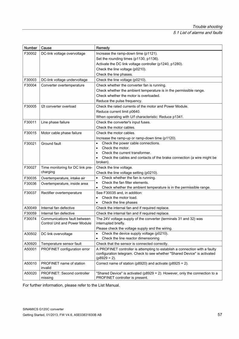
Trouble shooting 5.1 List of alarms and faults
SINAMICS G120C converter Getting Started, 01/2013, FW V4.6, A5E03831830B AB 57
Number Cause Remedy F30002 DC-link voltage overvoltage Increase the ramp-down time (p1121).
Set the rounding times (p1130, p1136). Activate the DC link voltage controller (p1240, p1280). Check the line voltage (p0210). Check the line phases.
F30003 DC-link voltage undervoltage Check the line voltage (p0210). F30004 Converter overtemperature Check whether the converter fan is running.
Check whether the ambient temperature is in the permissible range. Check whether the motor is overloaded. Reduce the pulse frequency.
F30005 I2t converter overload Check the rated currents of the motor and Power Module. Reduce current limit p0640. When operating with U/f characteristic: Reduce p1341.
F30011 Line phase failure Check the converter's input fuses. Check the motor cables.
F30015 Motor cable phase failure Check the motor cables. Increase the ramp-up or ramp-down time (p1120).
F30021 Ground fault Check the power cable connections. Check the motor. Check the current transformer. Check the cables and contacts of the brake connection (a wire might be broken).
F30027 Time monitoring for DC link pre-charging
Check the line voltage. Check the line voltage setting (p0210).
F30035 Overtemperature, intake air F30036 Overtemperature, inside area
Check whether the fan is running. Check the fan filter elements. Check whether the ambient temperature is in the permissible range.
F30037 Rectifier overtemperature See F30035 and, in addition: Check the motor load. Check the line phases
A30049 Internal fan defective Check the internal fan and if required replace. F30059 Internal fan defective Check the internal fan and if required replace. F30074 Communications fault between
Control Unit and Power Module The 24V voltage supply of the converter (terminals 31 and 32) was interrupted briefly. Please check the voltage supply and the wiring.
A30502 DC link overvoltage Check the device supply voltage (p0210). Check the line reactor dimensioning
A30920 Temperature sensor fault Check that the sensor is connected correctly. A50001 PROFINET configuration error A PROFINET controller is attempting to establish a connection with a faulty
configuration telegram. Check to see whether "Shared Device" is activated (p8929 = 2).
A50010 PROFINET name of station invalid
Correct name of station (p8920) and activate (p8925 = 2).
A50020 PROFINET: Second controller missing
"Shared Device" is activated (p8929 = 2). However, only the connection to a PROFINET controller is present.
For further information, please refer to the List Manual.
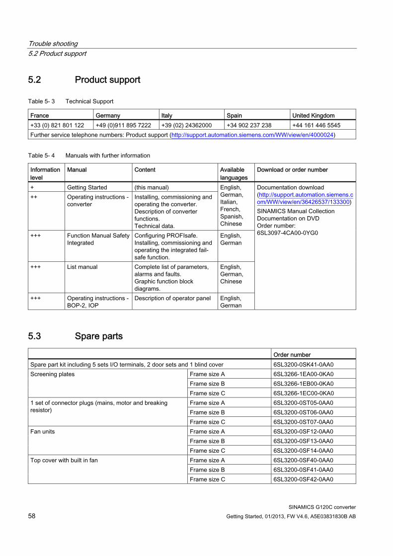
Trouble shooting 5.2 Product support
SINAMICS G120C converter 58 Getting Started, 01/2013, FW V4.6, A5E03831830B AB
5.2 Product support
Table 5- 3 Technical Support
France Germany Italy Spain United Kingdom +33 (0) 821 801 122 +49 (0)911 895 7222 +39 (02) 24362000 +34 902 237 238 +44 161 446 5545 Further service telephone numbers: Product support (http://support.automation.siemens.com/WW/view/en/4000024)
Table 5- 4 Manuals with further information
Information level
Manual Content Available languages
Download or order number
+ Getting Started (this manual) ++ Operating instructions -
converter Installing, commissioning and operating the converter. Description of converter functions. Technical data.
English, German, Italian, French, Spanish, Chinese
+++ Function Manual Safety Integrated
Configuring PROFIsafe. Installing, commissioning and operating the integrated fail-safe function.
English, German
+++ List manual Complete list of parameters, alarms and faults. Graphic function block diagrams.
English, German, Chinese
+++ Operating instructions - BOP-2, IOP
Description of operator panel English, German
Documentation download (http://support.automation.siemens.com/WW/view/en/36426537/133300) SINAMICS Manual Collection Documentation on DVD Order number: 6SL3097-4CA00-0YG0
5.3 Spare parts Order number Spare part kit including 5 sets I/O terminals, 2 door sets and 1 blind cover 6SL3200-0SK41-0AA0
Frame size A 6SL3266-1EA00-0KA0 Frame size B 6SL3266-1EB00-0KA0
Screening plates
Frame size C 6SL3266-1EC00-0KA0 Frame size A 6SL3200-0ST05-0AA0 Frame size B 6SL3200-0ST06-0AA0
1 set of connector plugs (mains, motor and breaking resistor)
Frame size C 6SL3200-0ST07-0AA0 Frame size A 6SL3200-0SF12-0AA0 Frame size B 6SL3200-0SF13-0AA0
Fan units
Frame size C 6SL3200-0SF14-0AA0 Frame size A 6SL3200-0SF40-0AA0 Frame size B 6SL3200-0SF41-0AA0
Top cover with built in fan
Frame size C 6SL3200-0SF42-0AA0


www.siemens.com/sinamics-g120
We reserve the right to make technical changes.© Siemens AG 2013
Siemens AGIndustry SectorDrive TechnologiesMotion Control SystemsP.O. Box 318091050 ERLANGENGERMANY
Related Documents