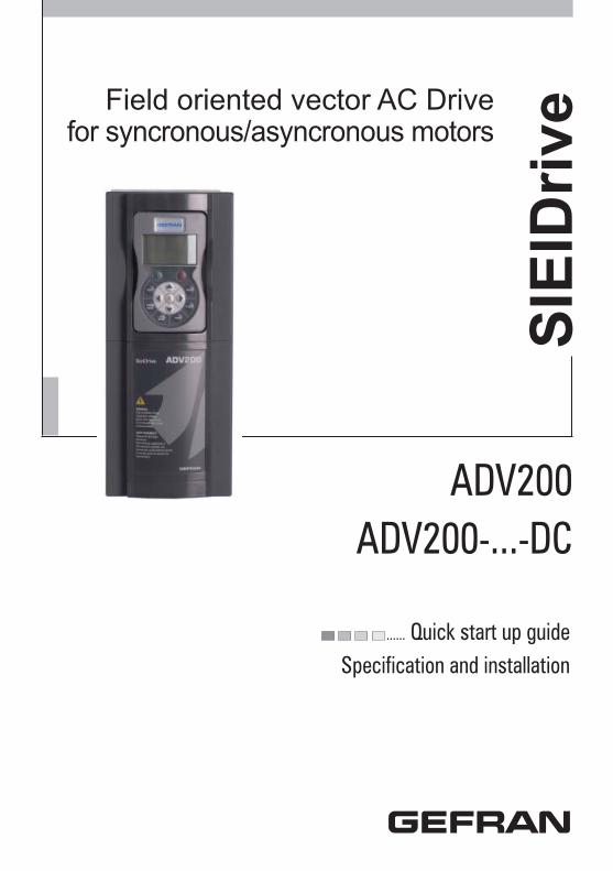
...... Quick start up guide Specification and installation SIEIDrive Field oriented vector AC Drive for syncronous/asyncronous motors ADV200 ADV200-...-DC

Welcome message from author
This document is posted to help you gain knowledge. Please leave a comment to let me know what you think about it! Share it to your friends and learn new things together.
Transcript
...... Quick start up guide Specification and installation
SIE
IDriv
eField oriented vector AC Drivefor syncronous/asyncronous motors
ADV200ADV200-...-DC
2 ADV200 • Quick start up guide - Specification and installation
Information about this manual
The ADV200 Quick start guide is a handy-sized manual for mechanical installation, electrical connection and fast start-up. The manual explaining the functions and a description of the parameters and the manuals of the expansions and fi eld bus can be found on the CD provided with the drive.
Software versionThis manual is updated according the software version V 5.X.0Variation of the number replacing “X” have no infl uence on the functionality of the device.
The identifi cation number of the software version is indicated on the identifi cation plate of the drive or can be checked with the Firmware ver.rel - PAR 490 parameter, menu 2.5.
General information
Note ! In industry, the terms “Inverter”, “Regulator” and “Drive” are sometimes interchanged. In this document, the term “Drive” will be used.
Before using the product, read the safety instruction section carefully. Keep the manual in a safe place and available to engineering and installation personnel during the product function-ing period.Gefran S.p.A has the right to modify products, data and dimensions without notice. The data can only be used for the product description and they can not be understood as legally stated properties.
Thank you for choosing this Gefran product.We will be glad to receive any possible information which could help us improvingthis manual. The e-mail address is the following: [email protected] rights reserved
ADV200 • Quick start up guide - Specification and installation 3
Table of contents
Information about this manual ................................................. 21 - Safety Precautions ............................................................... 61.1 Symbols used in the manual ............................................................................61.2 Safety precaution ..............................................................................................71.3 General warnings .............................................................................................71.4 Instruction for compliance with UL Mark (UL requirements), U.S. and Canadian electrical codes .......................................................................................................9
2 - Introduction to the product ................................................ 112.1 Drive type designation ....................................................................................12
2.1.1 Parallel inverters ..............................................................................................................13
3 - Transport and storage ........................................................ 143.1 General ...........................................................................................................143.2 Permissible Environmental Conditions ...........................................................15
4 - Mechanical installation ...................................................... 164.1 Inclination and mounting clearance ................................................................164.2 Fastening positions .........................................................................................17
5 - Wiring Procedure ................................................................ 225.1 Power section .................................................................................................25
5.1.1 Cable Cross Section ........................................................................................................255.1.2 Connection of shielding ...................................................................................................275.1.3 EMC guide line ................................................................................................................285.1.4 Block diagram power section ...........................................................................................295.1.5 Internal EMC fi lter ............................................................................................................315.1.6 Power line connection ......................................................................................................325.1.7 Input mains choke (L1) ....................................................................................................355.1.8 Motor connection .............................................................................................................365.1.9 Braking unit connection (optional) ...................................................................................375.1.10 Parallel connection on the AC (Input) and DC (Intermediate Circuit) side of several inverters ....................................................................................................................................385.1.11 Parallel DC connection...................................................................................................395.1.12 Connection of fans .........................................................................................................40
5.2 Regulation section ..........................................................................................425.2.1 Removing the terminal cover ...........................................................................................425.2.2 Cable Cross Section ........................................................................................................425.2.3 Regulation section connection .........................................................................................425.2.4 Switches, jumpers and LED .............................................................................................445.2.5 Power supply unit regulation card (only for sizes ≥ 71600) .............................................47
5.3 Braking ...........................................................................................................495.3.1 Braking unit ......................................................................................................................49
5.4 Encoder ..........................................................................................................515.5 Serial interface (XS connector) .......................................................................51
5.5.1 Drive / RS 485 Port (not insulated) point-to-point connection ..........................................515.5.2 Drive / RS485 port point-to-point connection (with insulation) .........................................535.5.3 RS 485 multi-drop connection .........................................................................................53
5.6 Typical connection diagrams ..........................................................................54
6 - Use of the keypad ............................................................... 586.1 Description ......................................................................................................586.2 Navigation .......................................................................................................59
6.2.1 Scanning of the fi rst and second level menus .................................................................596.2.2 Display of a parameter .....................................................................................................596.2.3 Scanning of the parameters ............................................................................................606.2.4 List of the last parameters modifi ed .................................................................................606.2.5 “Goto parameter” function ................................................................................................60
4 ADV200 • Quick start up guide - Specification and installation
6.3 Parameter modifi cation ...................................................................................616.4 How to save parameters .................................................................................626.5 Confi guration of the display ............................................................................63
6.5.1 Language selection ..........................................................................................................636.5.2 Selection of Easy / Export mode ......................................................................................636.5.3 Startup display .................................................................................................................636.5.4 Back-lighting of the display ..............................................................................................63
6.6 Alarms .............................................................................................................646.6.1 Alarm reset .......................................................................................................................64
6.7 Messages .......................................................................................................646.8 Saving and recovery of new parameter settings ............................................65
6.8.1 Selection of the keypad memory .....................................................................................656.8.2 Saving of parameters on the keypad ...............................................................................656.8.3 Load parameters from keypad .........................................................................................666.8.4 Transfer of parameters between drives ...........................................................................66
7 - Commissioning via keypad (STARTUP WIZARD) ............ 677.1 Startup Wizard ................................................................................................71
7.1.1 Startup Wizard for Asynchronous Motors ........................................................................717.1.2 Startup Wizard for Synchronous Motors ..........................................................................79
7.2 First customized start-up ................................................................................867.2.1 For Asynchronous Motors ................................................................................................867.2.2 For Synchronous Motors and FOC-CL control ................................................................90
7.3 Programming ..................................................................................................947.3.1 Menu display modes ........................................................................................................947.3.3 Variable interconnections mode .......................................................................................957.3.4 Multiple destination ..........................................................................................................97
8 - Troubleshooting .................................................................. 988.1 Alarms .............................................................................................................98
8.1.1 Speed fbk loss alarm according to the type of feedback ...............................................1048.2 Messages .....................................................................................................110
9 - Specifi cation ..................................................................... 1169.1 Environmental Conditions .............................................................................1169.2 Standards .....................................................................................................1169.3 Accuracy (Asyncronous) ...............................................................................116
9.3.1 Current control ............................................................................................................... 1169.3.2 Speed control ................................................................................................................. 1169.3.3 Speed control limits ....................................................................................................... 1179.3.4 Torque control ................................................................................................................ 1179.3.5 Overload ........................................................................................................................ 117
9.4 Accuracy (Synchronous) ...............................................................................1179.4.1 Current control ............................................................................................................... 1179.4.2 Speed control ................................................................................................................. 1179.4.3 Initial torque limit ............................................................................................................ 1179.4.4 Overload ........................................................................................................................ 1179.4.5 Flux reduction ................................................................................................................ 118
9.5 DC circuit ......................................................................................................1189.6 Input electrical data ......................................................................................119
9.6.1 AC power supply ............................................................................................................ 1199.6.2 DC power supply ...........................................................................................................120
9.7 Output electrical data ....................................................................................1219.7.1 Derating values for switching frequency ........................................................................1239.7.2 Overload for output frequency .......................................................................................124
9.8 Voltage level of the inverter for safe operations ...............................................1269.9 Cooling .........................................................................................................1279.10 Weight and dimensions ..............................................................................128
10 - Options ............................................................................ 13710.1 Optional external fuses ..............................................................................137
10.1.1 AC input side fuses (F1) ..............................................................................................13710.1.2 Fuses of the power section DC input side (F2) ............................................................138
ADV200 • Quick start up guide - Specification and installation 5
10.2 Choke .........................................................................................................13910.2.1 Optional input chokes (L1) ...........................................................................................13910.2.2 Optional external choke (L2) ........................................................................................139
10.3 External EMC fi lter (optional) ......................................................................14410.4 Braking resistor (optional) ...........................................................................14610.5 Installation of optional cards .......................................................................147
10.5.1 SLOT / Encoder Card Management ............................................................................14810.5.2 Procedure ...................................................................................................................14910.5.3 Shielding of optional card connections ........................................................................150
Appendix 1 - Parallel connection (400 ... 1000kW sizes) .... 151A 1.1 Introduction ................................................................................................151A 1.2 MS-SL interface cable wiring sizes 400...710 kW .....................................153A 1.2 MS-SL interface cable wiring sizes 900...1000 kW ...................................154A 1.4 Jumpers and Switches ..............................................................................155A 1.5 LEDs ..........................................................................................................155A 1.6 Scheda EXP-SFTy-ADV ............................................................................157
Appendix 2 - Miscellaneous .................................................. 158A 2.1 DC-link capacity ........................................................................................158A 2.2 Encoders ...................................................................................................159
A.2.3 - Phasing .......................................................................................................................161
6 ADV200 • Quick start up guide - Specification and installation
1 - Safety Precautions
1.1 Symbols used in the manual
Indicates a procedure, condition, or statement that, if not strictly observed, could result in personal injury or death.Indique le mode d’utilisation, la procédure et la condition d’exploitation. Si ces consignes ne sont passtrictement respectées, il y a des risques de blessures corporelles ou de mort.
Indicates a procedure, condition, or statement that, if not strictly observed, could result in damage to or destruction of equipment.Indique et le mode d’utilisation, la procédure et la condition d’exploitation. Si ces consignes ne sont pas strictement respectées, il y a des risques de détérioration ou de destruction des appareils.
Indicates that the presence of electrostatic discharge could damage the appliance. When handling the boards, always wear a grounded bracelet.Indique que la présence de décharges électrostatiques est susceptible d’endommager l’appa-reil. Toujours porter un bracelet de mise à la terre lors de la manipulation des cartes.
Indicates a procedure, condition, or statement that should be strictly followed in order to optimize these applications.Indique le mode d’utilisation, la procédure et la condition d’exploitation. Ces consignes doivent êtrerigoureusement respectées pour optimiser ces applications.
Note ! Indicates an essential or important procedure, condition, or statement.
Indique un mode d’utilisation, de procédure et de condition d’exploitation essentiels ou importants
Qualifi ed personnelFor the purpose of this Instruction Manual , a “Qualifi ed person” is someone who is skilled to the installation, mounting, start-up and operation of the equipment and the hazards involved. This operator must have the following qualifi cations:- trained in rendering fi rst aid.- trained in the proper care and use of protective equipment in accordance with
established safety procedures.- trained and authorized to energize, de-energize, clear, ground and tag circuits
and equipment in accordance with established safety procedures.Personne qualifi éeAux fi ns de ce manuel d’instructions, le terme « personne qualifi ée » désigne toute personne compétente en matière d’installation, de montage, de mise en service et de fonctionnement de l’appareil et au fait des dangers qui s’y rattachent. L’opérateur en question doit posséder les qualifi cations suivantes :- formation lui permettant de dispenser les premiers soins- formation liée à l’entretien et à l’utilisation des équipements de protection selon les consigne de sécurité en vigueur- formation et habilitation aux manoeuvres suivantes : branchement, débranchement,
Warning!
Caution
Attention
ADV200 • Quick start up guide - Specification and installation 7
vérifi cation des isolations, mise à la terre et étiquetage des circuits et des appareils selon les consignes de sécurité en vigueur
Use for intended purpose onlyThe power drive system (electrical drive + application plant) may be used only for the application stated in the manual and only together with devices and compo-nents recommended and authorized by Gefran.Utiliser uniquement dans les conditions prévuesLe système d’actionnement électrique (drive électrique + installation) ne peut être utilisé que dans les conditions d’exploitation et les lieux prévus dans le manuel et uniquement avec les dispositifs et les composants recommandés et autorisés par Gefran.
1.2 Safety precautionThe following instructions are provided for your safety and as a means of prevent-ing damage to the product or components in the machines connected. This sec-tion lists instructions, which apply generally when handling electrical drives. Specifi c instructions that apply to particular actions are listed at the beginning of each chapters.Les instructions suivantes sont fournies pour la sécurité de l’utilisateur tout comme pour éviter l’endommagement du produit ou des composants à l’intérieur des machines raccordées. Ce paragraphe dresse la liste des instructions généralement applicables lors de la manipulation des drives électriques.Les instructions spécifi ques ayant trait à des actions particulières sont répertoriées au début de chaque chapitre.
Read the information carefully, since it is provided for your personal safety and will also help prolong the service life of your electrical drive and the plant you connect to it.Lire attentivement les informations en matière de sécurité personnelle et visant par ailleurs à prolonger la durée de vie utile du drive tout comme de l’installation à laquelle il est relié.
1.3 General warnings
This equipment contains dangerous voltages and controls potentially dangerous rotat-ing mechanical parts. Non-compliance with Warnings or failure to follow the instructions contained in this manual can result in loss of life, severe personal injury or serious damage to property.Cet appareil utilise des tensions dangereuses et contrôle des organes mécaniques en mou-vement potentiellement dangereux. L’absence de mise en pratique des consignes ou le non-respect des instructions contenues dans ce manuel peuvent provoquer le décès, des lésions corporelles graves ou de sérieux dégâts aux équipements.
This equipment contains dangerous voltages and controls potentially dangerous rotat-ing mechanical parts. Non-compliance with Warnings or failure to follow the instructions contained in this manual can result in loss of life, severe personal injury or serious damage to property.Les drives occasionnent des mouvements mécaniques. L’utilisateur est tenu de s’assurer que de tels mouvements mécaniques ne débouchent pas sur des conditions d’insécurité. Les butées de sécurité et les seuils d’exploitation prévus par le fabricant ne doivent être ni contournés ni modifi és.
Only suitable qualifi ed personnel should work on this equipment, and only after becom-ing familiar with all safety notices, installation, operation and maintenance procedures contained in this manual. The successful and safe operation of this equipment is
Warning!
8 ADV200 • Quick start up guide - Specification and installation
dependent upon its proper handling,installation, operation and maintenance.Seul un personnel dûment formé peut intervenir sur cet appareil et uniquement après avoir assimilé l’ensemble des informations concernant la sécurité, les procédures d’installation, le fonctionnement et l’entretien contenues dans ce manuel. La sécurité et l’effi cacité du fonction-nement de cet appareil dépendent du bon accomplissement des opérations de manutention, d’installation, de fonctionnement et d’entretien.
In the case of faults, the drive, even if disabled, may cause accidental movements if it has not been disconnected from the mains supply.En cas de panne et même désactivé, le drive peut provoquer des mouvements fortuits s’il n’a pas été débranché de l’alimentation secteur.
Electrical Shock The DC link capacitors remain charged at a hazardous voltage even after cutting off the power supply.Never open the device or covers while the AC Input power supplyis switched on. Mini-mum time to wait before working on the terminals or inside the device is listed in section 9.6 .Risque de décharge électriqueLes condensateurs de la liaison à courant continu restent chargés à une tension dangereuse même après que la tension d’alimentation a été coupée.Ne jamais ouvrir l’appareil lorsqu’il est suns tension. Le temps minimum d’attente avant de pouvoir travailler sur les bornes ou bien àl’intérieur de l’appareil est indiqué dans la section 9.6 .
Electrical Shock and Burn Hazard:When using instruments such as oscilloscopes to work on live equipment, the oscil-loscope’s chassis should be grounded and a differential probe input should be used. Care should be used in the selection of probes and leads and in the adjustment of the oscilloscope so that accurate readings may be made. See instrument manufacturer’s instruction book for proper operation and adjustments to the instrument.Décharge Èlectrique et Risque de Brúlure : Lors de l’utilisation d’instruments (par example oscilloscope) sur des systémes en marche, le chassis de l’oscilloscope doit être relié à la terre et une sonde différentiel devrait être utilisé en entrée. Les sondes et conducteurs doivent être choissis avec soin pour effectuer les meilleures mesures à l’aide d’un oscilloscope. Voir le manuel d’instruction pour une utilisation correcte des instruments.
Fire and Explosion Hazard:Fires or explosions might result from mounting Drives in hazardous areas such as loca-tions where fl ammable or combustible vapors or dusts are present. Drives should be installed away from hazardous areas, even if used with motors suitable for use in these locations. Risque d’incendies et d’explosions: L’utilisation des drives dans des zônes à risques (pré-sence de vapeurs ou de poussières infl ammables), peut provoquer des incendies ou des explosions. Les drives doivent être installés loin des zônes dangeureuses, et équipés de moteurs appropriés.
ADV200 • Quick start up guide - Specification and installation 9
1.4 Instruction for compliance with UL Mark (UL require-ments), U.S. and Canadian electrical codes
Short circuit ratingsADV200 inverters must be connected to a grid capable of supplying a symmetrical short-circuit power of less than or equal to “xxxx A rms (at 480 V +10% V max).
The values of the “xxxx” A rms short-circuit current, in accordance with UL require-ments (UL 508 c), for each motor power rating (Pn mot in the manual) are shown in the table below.
Short current rating
Pn mot (kW) SCCR ( A ) @480Vac
1,1...37,3 5000
39....149 10000
150....398 18000
299.....447 30000
448 ... 671 42000
672 ... 1193 85000
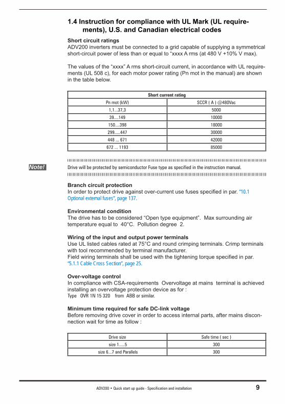
Note! Drive will be protected by semiconductor Fuse type as specified in the instruction manual.
Branch circuit protectionIn order to protect drive against over-current use fuses specifi ed in par. “10.1 Optional external fuses”, page 137.
Environmental conditionThe drive has to be considered “Open type equipment”. Max surrounding air temperature equal to 40°C. Pollution degree 2.
Wiring of the input and output power terminalsUse UL listed cables rated at 75°C and round crimping terminals. Crimp terminals with tool recommended by terminal manufacturer.Field wiring terminals shall be used with the tightening torque specifi ed in par. “5.1.1 Cable Cross Section”, page 25.
Over-voltage controlIn compliance with CSA-requirements Overvoltage at mains terminal is achieved installing an overvoltage protection device as for :Type OVR 1N 15 320 from ABB or similar.
Minimum time required for safe DC-link voltageBefore removing drive cover in order to access internal parts, after mains discon-nection wait for time as follow :
Drive size Safe time ( sec )
size 1.....5 300
size 6...7 and Parallels 300
10 ADV200 • Quick start up guide - Specification and installation
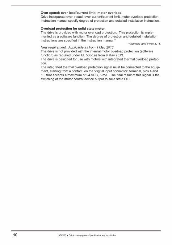
Over-speed; over-load/current limit; motor overloadDrive incorporate over-speed, over-current/current limit, motor overload protection. Instruction manual specify degree of protection and detailed installation instruction.
Overload protection for solid state motor.The drive is provided with motor overload protection. This protection is imple-mented as a software function. The degree of protection and detailed installation instructions are specifi ed in the instruction manual.*
*Applicable up to 9 May 2013.New requirement. Applicable as from 9 May 2013.The drive is not provided with the internal motor overload protection (software function) as required under UL 508c as from 9 May 2013.The drive is designed for use with motors with integrated thermal overload protec-tion.The integrated thermal overload protection signal must be connected to the equip-ment, starting from a contact, on the “digital input connector” terminal, pins 4 and 10, that accepts a maximum of 24 VDC, 5 mA. The fi nal result of this signal is the switching of the motor control device output to solid state OFF.
ADV200 • Quick start up guide - Specification and installation 11
2 - Introduction to the product
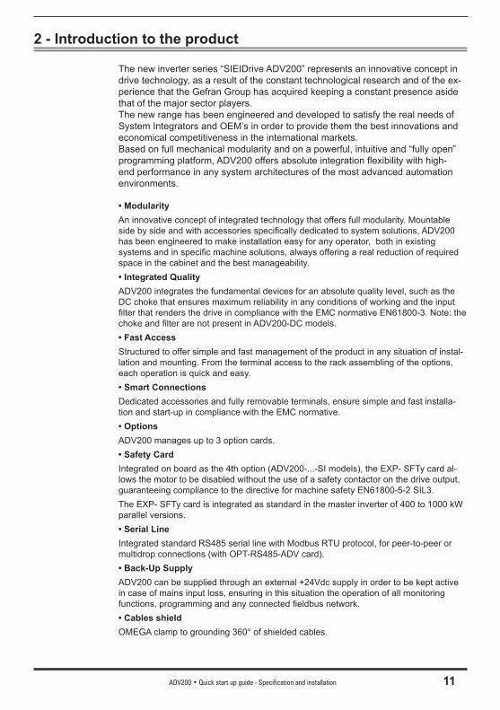
The new inverter series “SIEIDrive ADV200” represents an innovative concept in drive technology, as a result of the constant technological research and of the ex-perience that the Gefran Group has acquired keeping a constant presence aside that of the major sector players.The new range has been engineered and developed to satisfy the real needs of System Integrators and OEM’s in order to provide them the best innovations and economical competitiveness in the international markets.Based on full mechanical modularity and on a powerful, intuitive and “fully open” programming platform, ADV200 offers absolute integration fl exibility with high-end performance in any system architectures of the most advanced automation environments.
• Modularity An innovative concept of integrated technology that offers full modularity. Mountable side by side and with accessories specifi cally dedicated to system solutions, ADV200 has been engineered to make installation easy for any operator, both in existing systems and in specifi c machine solutions, always offering a real reduction of required space in the cabinet and the best manageability.• Integrated Quality ADV200 integrates the fundamental devices for an absolute quality level, such as the DC choke that ensures maximum reliability in any conditions of working and the input fi lter that renders the drive in compliance with the EMC normative EN61800-3. Note: the choke and fi lter are not present in ADV200-DC models.• Fast Access Structured to offer simple and fast management of the product in any situation of instal-lation and mounting. From the terminal access to the rack assembling of the options, each operation is quick and easy.• Smart Connections Dedicated accessories and fully removable terminals, ensure simple and fast installa-tion and start-up in compliance with the EMC normative.• Options ADV200 manages up to 3 option cards.• Safety Card Integrated on board as the 4th option (ADV200-...-SI models), the EXP- SFTy card al-lows the motor to be disabled without the use of a safety contactor on the drive output, guaranteeing compliance to the directive for machine safety EN61800-5-2 SIL3.The EXP- SFTy card is integrated as standard in the master inverter of 400 to 1000 kW parallel versions.• Serial Line Integrated standard RS485 serial line with Modbus RTU protocol, for peer-to-peer or multidrop connections (with OPT-RS485-ADV card).• Back-Up Supply ADV200 can be supplied through an external +24Vdc supply in order to be kept active in case of mains input loss, ensuring in this situation the operation of all monitoring functions, programming and any connected fi eldbus network.• Cables shield OMEGA clamp to grounding 360° of shielded cables.
12 ADV200 • Quick start up guide - Specification and installation
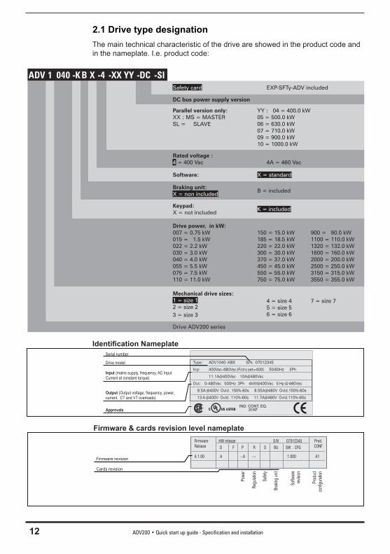
2.1 Drive type designationThe main technical characteristic of the drive are showed in the product code and in the nameplate. I.e. product code:
ADV 1 040 -K B X -4 -XX YY -DC -SISafety card EXP-SFTy-ADV included
DC bus power supply version
Parallel version only:XX : MS = MASTERSL = SLAVE
YY : 04 = 400.0 kW05 = 500.0 kW06 = 630.0 kW07 = 710.0 kW09 = 900.0 kW10 = 1000.0 kW
Rated voltage :4 = 400 Vac 4A = 460 Vac
Software: X = standard
Braking unit:X = non included
B = included
Keypad:X = not included
K = included
Drive power, in kW:007 = 0.75 kW015 = 1.5 kW022 = 2.2 kW030 = 3.0 kW040 = 4.0 kW055 = 5.5 kW075 = 7.5 kW110 = 11.0 kW
150 = 15.0 kW185 = 18.5 kW220 = 22.0 kW300 = 30.0 kW370 = 37.0 kW450 = 45.0 kW550 = 55.0 kW750 = 75.0 kW
900 = 90.0 kW1100 = 110.0 kW1320 = 132.0 kW1600 = 160.0 kW2000 = 200.0 kW2500 = 250.0 kW3150 = 315.0 kW3550 = 355.0 kW
Mechanical drive sizes:1 = size 12 = size 23 = size 3
4 = size 45 = size 56 = size 6
7 = size 7
Drive ADV200 series
Identifi cation Nameplate
Type : ADV1040 -KBX S/N: 07012345
Inp: 400Vac-480Vac (Fctry set=400) 50/60Hz 3Ph
11.1A@400Vac 10A@480Vac
Out : 0-480Vac 500Hz 3Ph 4kW@400Vac 5 Hp @ 460Vac
9.5A @400V Ovld . 150%-60s 8.55A@460V Ovld.150%-60s
13 A @400V Ovld . 110%-60s 11.7A@460V Ovld.110%-60s
®
Drive model
Serial number
Input (mains supply, frequency, AC InputCurrent at constant torque)
Output (Output voltage, frequency, power,current, CT and VT overloads)
ApprovalsIND. CONT. EQ.
31KF
Firmware & cards revision level nameplateFirmware HW release S/N 07012345 Prod.Release D F P R S BU SW . CFG CONF
A 1.00 A -.A -.- 1.000 A1
Cards revision
Firmware revision
Pow
er
Reg
ulat
ion
Saf
ety
Bra
king
uni
t
Sof
twar
ere
visi
on
Pro
duct
conf
igur
atio
n
ADV200 • Quick start up guide - Specification and installation 13
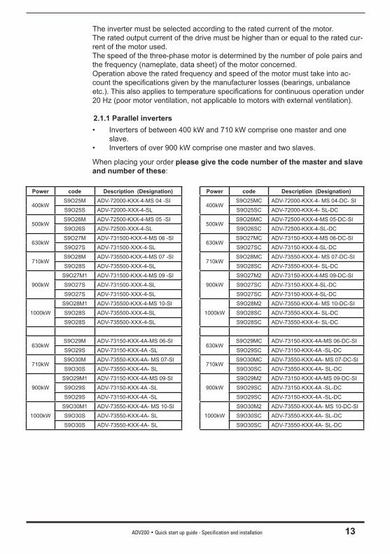
The inverter must be selected according to the rated current of the motor. The rated output current of the drive must be higher than or equal to the rated cur-rent of the motor used.The speed of the three-phase motor is determined by the number of pole pairs and the frequency (nameplate, data sheet) of the motor concerned.Operation above the rated frequency and speed of the motor must take into ac-count the specifi cations given by the manufacturer losses (bearings, unbalance etc.). This also applies to temperature specifi cations for continuous operation under 20 Hz (poor motor ventilation, not applicable to motors with external ventilation).
2.1.1 Parallel inverters• Inverters of between 400 kW and 710 kW comprise one master and one
slave.• Inverters of over 900 kW comprise one master and two slaves.
When placing your order please give the code number of the master and slave and number of these:
Power code Description (Designation) Power code Description (Designation)
400kWS9O25M ADV-72000-KXX-4-MS 04 -SI
400kWS9O25MC ADV-72000-KXX-4- MS 04-DC- SI
S9O25S ADV-72000-XXX-4-SL S9O25SC ADV-72000-KXX-4- SL-DC
500kWS9O26M ADV-72500-KXX-4-MS 05 -SI
500kWS9O26MC ADV-72500-KXX-4-MS 05-DC-SI
S9O26S ADV-72500-XXX-4-SL S9O26SC ADV-72500-KXX-4-SL-DC
630kWS9O27M ADV-731500-KXX-4-MS 06 -SI
630kWS9O27MC ADV-73150-KXX-4-MS 06-DC-SI
S9O27S ADV-731500-XXX-4-SL S9O27SC ADV-73150-KXX-4-SL-DC
710kWS9O28M ADV-735500-KXX-4-MS 07 -SI
710kWS9O28MC ADV-73550-KXX-4- MS 07-DC-SI
S9O28S ADV-735500-XXX-4-SL S9O28SC ADV-73550-KXX-4- SL-DC
900kW
S9O27M1 ADV-731500-KXX-4-MS 09 -SI
900kW
S9O27M2 ADV-73150-KXX-4-MS 09-DC-SI
S9O27S ADV-731500-XXX-4-SL S9O27SC ADV-73150-KXX-4-SL-DC
S9O27S ADV-731500-XXX-4-SL S9O27SC ADV-73150-KXX-4-SL-DC
1000kW
S9O28M1 ADV-735500-KXX-4-MS 10-SI
1000kW
S9O28M2 ADV-73550-KXX-4- MS 10-DC-SI
S9O28S ADV-735500-XXX-4-SL S9O28SC ADV-73550-KXX-4- SL-DC
S9O28S ADV-735500-XXX-4-SL S9O28SC ADV-73550-KXX-4- SL-DC
630kWS9O29M ADV-73150-KXX-4A-MS 06-SI
630kWS9O29MC ADV-73150-KXX-4A-MS 06-DC-SI
S9O29S ADV-73150-KXX-4A -SL S9O29SC ADV-73150-KXX-4A -SL-DC
710kWS9O30M ADV-73550-KXX-4A- MS 07-SI
710kWS9O30MC ADV-73550-KXX-4A- MS 07-DC-SI
S9O30S ADV-73550-KXX-4A- SL S9O30SC ADV-73550-KXX-4A- SL-DC
900kW
S9O29M1 ADV-73150-KXX-4A-MS 09-SI
900kW
S9O29M2 ADV-73150-KXX-4A-MS 09-DC-SI
S9O29S ADV-73150-KXX-4A -SL S9O29SC ADV-73150-KXX-4A -SL-DC
S9O29S ADV-73150-KXX-4A -SL S9O29SC ADV-73150-KXX-4A -SL-DC
1000kW
S9O30M1 ADV-73550-KXX-4A- MS 10-SI
1000kW
S9O30M2 ADV-73550-KXX-4A- MS 10-DC-SI
S9O30S ADV-73550-KXX-4A- SL S9O30SC ADV-73550-KXX-4A- SL-DC
S9O30S ADV-73550-KXX-4A- SL S9O30SC ADV-73550-KXX-4A- SL-DC
14 ADV200 • Quick start up guide - Specification and installation
3 - Transport and storage
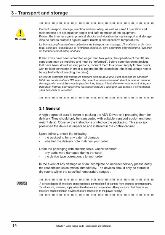
Correct transport, storage, erection and mounting, as well as careful operation and maintenance are essential for proper and safe operation of the equipment.Protect the inverter against physical shocks and vibration during transport and storage. Also be sure to protect it against water (rainfall) and excessive temperatures.Le bon accomplissement des opérations de transport, de stockage, d’installation et de mon-tage, ainsi que l’exploitation et l’entretien minutieux, sont essentiels pour garantir à l’appareil un fonctionnement adéquat et sûr.
If the Drives have been stored for longer than two years, the operation of the DC link capacitors may be impaired and must be “reformed”. Before commissioning devices that have been stored for long periods, connect them to a power supply for two hours with no load connected in order to regenerate the capacitors, (the input voltage has to be applied without enabling the drive).En cas de stockage des variateurs pendant plus de deux ans, il est conseillé de contrôler l’état des condensateurs CC avant d’en effectuer le branchement. Avant la mise en service des appareils, ayant été stockés pendant long temps, il faut alimenter variateurs à vide pen-dant deux heures, pour régénérer les condensateurs : appliquer une tension d’alimentation sans actionner le variateur.
3.1 GeneralA high degree of care is taken in packing the ADV Drives and preparing them for delivery. They should only be transported with suitable transport equipment (see weight data). Observe the instructions printed on the packaging. This also ap-plieswhen the device is unpacked and installed in the control cabinet.
Upon delivery, check the following:- the packaging for any external damage- whether the delivery note matches your order.
Open the packaging with suitable tools. Check whether:- any parts were damaged during transport- the device type corresponds to your order
In the event of any damage or of an incomplete or incorrect delivery please notify the responsible sales offi ces immediately. The devices should only be stored in dry rooms within the specifi ed temperature ranges .
Note! A certain degree of moisture condensation is permissible if this arises from changes in temperature. This does not, however, apply when the devices are in operation. Always ensure that there is no moisture condensation in devices that are connected to the power supply!
Caution

ADV200 • Quick start up guide - Specification and installation 15
3.2 Permissible Environmental ConditionsTemperaturestorage ____________________ -25…+55°C (-13…+131°F), class 1K4 per EN50178
-20…+55°C (-4…+131°F), for devices with keypadtransport ___________________ -25…+70°C (-13…+158°F), class 2K3 per EN50178
-20…+60°C (-4…+140°F), for devices with keypad
Air humiditystorage ____________________ 5% to 95 %, 1 g/m3 to 29 g/m3 (class 1K3 as per EN50178)transport ___________________ 95 % (3), 60 g/m3 (4) A light condensation of moisture may occur for a short time occasionally if the device is not in operation
(class 2K3 as per EN50178)
Air pressure:storage ____________________ [kPa] 86 to 106 (class 1K4 as per EN50178)transport ___________________ [kPa] 70 to 106 (class 2K3 as per EN50178)
(3) Greatest relative air humidity occurs with the temperature @ 40°C (104°F) or if the temperature of the device is brought suddenly from -25 ...+30°C (-13°...+86°F).
(4) Greatest absolute air humidity if the device is brought suddenly from 70...15°C (158°...59°F).
The drive is suitable for use under the environmental service conditions (climate, mechanical, pollution, etc.) defi ned as usual service conditions according to EN61800-2.Attention
16 ADV200 • Quick start up guide - Specification and installation
4 - Mechanical installation
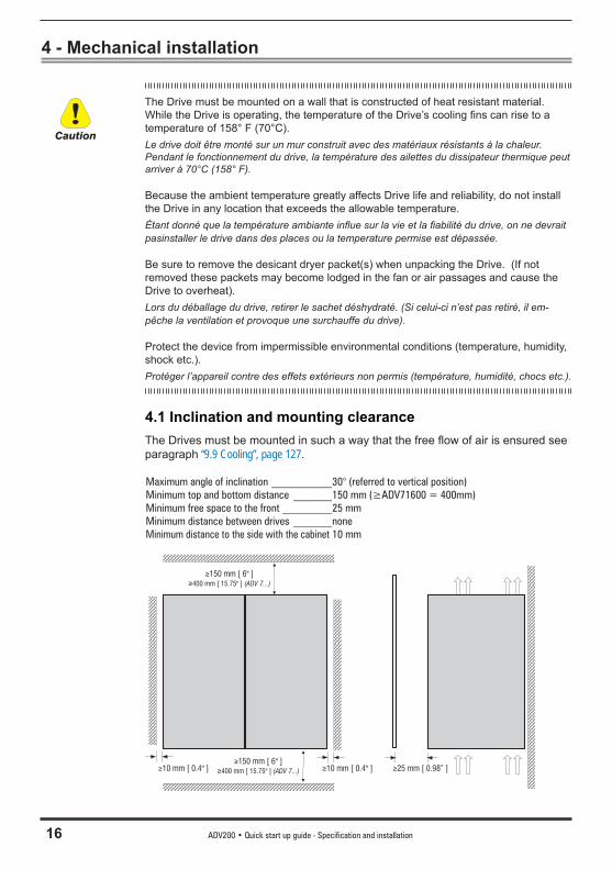
The Drive must be mounted on a wall that is constructed of heat resistant material. While the Drive is operating, the temperature of the Drive’s cooling fi ns can rise to a temperature of 158° F (70°C).Le drive doit être monté sur un mur construit avec des matériaux résistants à la chaleur. Pendant le fonctionnement du drive, la température des ailettes du dissipateur thermique peut arriver à 70°C (158° F).
Because the ambient temperature greatly affects Drive life and reliability, do not install the Drive in any location that exceeds the allowable temperature.Étant donné que la température ambiante infl ue sur la vie et la fi abilité du drive, on ne devrait pasinstaller le drive dans des places ou la temperature permise est dépassée.
Be sure to remove the desicant dryer packet(s) when unpacking the Drive. (If not removed these packets may become lodged in the fan or air passages and cause the Drive to overheat).Lors du déballage du drive, retirer le sachet déshydraté. (Si celui-ci n’est pas retiré, il em-pêche la ventilation et provoque une surchauffe du drive).
Protect the device from impermissible environmental conditions (temperature, humidity, shock etc.).Protéger l’appareil contre des effets extérieurs non permis (température, humidité, chocs etc.).
4.1 Inclination and mounting clearanceThe Drives must be mounted in such a way that the free fl ow of air is ensured see paragraph “9.9 Cooling”, page 127.
Maximum angle of inclination ___________30° (referred to vertical position)Minimum top and bottom distance _______150 mm (≥ADV71600 = 400mm)Minimum free space to the front _________25 mmMinimum distance between drives _______noneMinimum distance to the side with the cabinet 10 mm
10 mm [ 0.4" ]≥
≥
400 mm [ 15.75" ] (ADV 7...)
150 mm [ 6" ]≥
25 mm [ 0.98” ]≥10 mm [ 0.4" ]≥
≥150 mm [ 6" ]≥400 mm [ 15.75" ] (ADV 7...)
Caution
ADV200 • Quick start up guide - Specification and installation 17
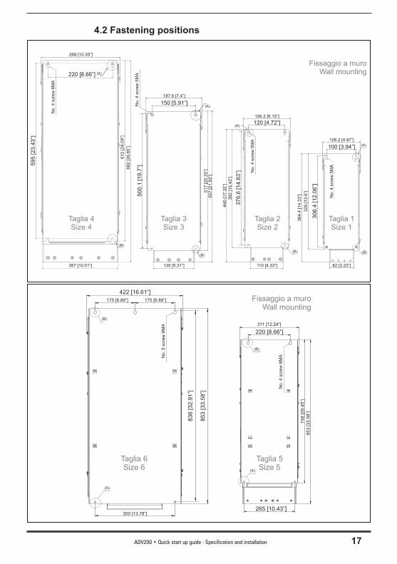
4.2 Fastening positions
Taglia 3Size 3
150 [5.91”]
500.1
[19.7
”]
(A)No.4
scre
w5M
A
(B)
(A)120 [4.72”]
Taglia 2Size 2
376.6
[14.8
3”]
Taglia 1Size 1
No.4
scre
w5M
A
(B)
100 [3.94”]
306.4
[12.0
6”]
Fissaggio a muroWall mounting
(A)
126.2 [4.97”]
364.4
[14.3
3”]
320
[12.6
”]
82 [3.23”]
(B)N
o.4
scre
w5M
A
156.2 [6.15”]
392
[15.4
3”]
440
[17.3
2”]
135 [5.31”]
187.6 [7.4”]
557
[21.9
3”]
517
[20.3
5”]
110 [4.33”]
Taglia 4Size 4
220 [8.66”]
612
[24.0
9”]
595
[23.4
3”]
(A)
(B)
No.4
scre
w6M
A268 [10.55”]
682
[26.8
5”]
267 [10.51”]
Fissaggio a muroWall mounting
No.5
scre
w6M
A
Taglia 6Size 6
Taglia 5Size 5
(B)
(A)
(B)
(A)
No.4
scre
w6M
A
422 [16.61”]
350 [13.78”]
175 [6.89”]
836
[32.9
1”]
175 [6.89”]
853
[33.5
8”]
311 [12.24”]
220 [8.66”]
853
[33.5
8”]
748
[29.4
5”]
265 [10.43”]
18 ADV200 • Quick start up guide - Specification and installation
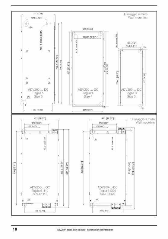
ADV200-...-DCTaglia 3Size 3
150 [5.91”]
50
0.1
[1
9.7
”]
(A)No
. 4
scre
w 5
MA
(B)
Fissaggio a muroWall mounting
187.6 [7.4”]
51
7 [
20
.35
”]
ADV200-...-DCTaglia 4Size 4
220 [8.66”]
61
2 [
24
.09
”]
59
5 [
23
.43
”]
(A)
(B)
No
. 4
scre
w 6
MA
268 [10.55”]
61
6 [
24
.25
”]
267 [10.51”]
ADV200-...-DCTaglia 5Size 5
(B)
(A)
No. 4 s
cre
w 6
MA
311 [12.24”]
190 [7.48”]
73
0.4
[2
8.7
6”]
74
8 [
29
.45
”]
265 [10.43”]
Fissaggio a muroWall mounting
No. 5 s
cre
w 6
MA
ADV200-...-DCTaglia 61110Size 61110
(B)
421 [16.57”]
350 [13.78”]
175 [6.89”]
83
6 [
32
.91
”]
85
3 [
33
.58
”]
(B)
(A) (A)
350 [13.78”]
175 [6.89”]
275 [10.83”] 275 [10.83”]
421 [16.57”]
88
8 [
34
.96
”]
No. 5 s
cre
w 6
MA
92
4.5
[3
6.4
”]
83
6 [
32
.91
”]
86
5.5
[3
4.0
7”]
ADV200-...-DCTaglia 61320Size 61320
ADV200 • Quick start up guide - Specification and installation 19
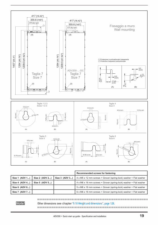
Taglia 7Size 7
417 [16.42”]
177.8 [7.00”]
355.6 [140”]126
4[4
9.7
6”]
1209
.5[4
7.6
2”]
Fissaggio a muroWall mounting
(B)(A)
6.5[0.26”]
6.5[0.26”]
Ø 13
[0.51”]
19
[0.7
5”]
17.45[0.69”]
15.2
5[0
.6”]
(A)
(B)
1407
[55.4
”]
(*) Protezione in policarbonato trasparente(*) Protective trasparent policarbonate
(*)
(*)
ADV200-...-DC
Taglia 7Size 7
417 [16.42”]
177.8 [7.00”]
355.6 [140”]
126
4[4
9.7
6”]
1209
.5[4
7.6
2”]
(A)
(B)
(B)(A)
7.2
5[0
.29”]
5.5 [0.21”]
5.5 [0.21”]
15
[0.5
9”]
Ø 10 [0.39”]
11.2
5[0
.44”]
6.5 [0.26”]
Ø 13 [0.51”]
19
[0.7
5”]
6.5 [0.26”]
12.5 [0.49”]
12
[0.4
7”]
Taglie 1-2-3Sizes 1-2-3
Taglia 4Size 4
(B)(A)
Taglia 5Size 5
(B)(A)
6.5 [0.26”]
19
[0.7
5”]
Ø 13 [0.51”]
6.5 [0.26”]
12
[0.4
7”]
12.75 [0.50”]
(B)(A)
Taglia 6Size 6
6.5 [0.26”]
6.5 [0.26”]
Ø 13 [0.51”]
19
[0.7
5”]
24.95 [0.98”]
12
[0.4
7”]
Recommended screws for fastening
Size 1 (ADV 1...) Size 2 (ADV 2...) Size 3 (ADV 3...) 4 x M5 x 12 mm screws + Grover (spring-lock) washer + Flat washer
Size 4 (ADV 4...) Size 5 (ADV 5...) 4 x M6 x 16 mm screws + Grover (spring-lock) washer + Flat washer
Size 6 (ADV 6...) 5 x M6 x 16 mm screws + Grover (spring-lock) washer + Flat washer
Size 7 (ADV 7...) 6 x M6 x 16 mm screws + Grover (spring-lock) washer + Flat washer
Note! Other dimensions see chapter “9.10 Weight and dimensions”, page 128.
20 ADV200 • Quick start up guide - Specification and installation
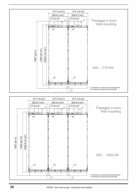
417 [16.42”]
177.8 [7.00”]
355.6 [140”]
126
4[4
9.7
6”]
1209
.5[4
7.6
2”]
Fissaggio a muroWall mounting
(A)
(B)
417 [16.42”]
177.8 [7.00”]
355.6 [140”]
(A)
(B)
400 ... 710 kW
(*) Protezione in policarbonato trasparente(*) Protective trasparent policarbonate
1407
[55.4
”]
(*) (*)
(*)
417 [16.42”]
177.8 [7.00”]
355.6 [140”]
12
64
[49
.76
”]
12
09
.5[4
7.6
2”]
Fissaggio a muroWall mounting
(A)
(B)
417 [16.42”]
177.8 [7.00”]
355.6 [140”]
(A)
(B)
900 ... 1000 kW
417 [16.42”]
177.8 [7.00”]
355.6 [140”]
(A)
(B)
14
07
[55
.4”]
(*) Protezione in policarbonato trasparente(*) Protective trasparent policarbonate
(*) (*)
(*) (*)
(*)
ADV200 • Quick start up guide - Specification and installation 21
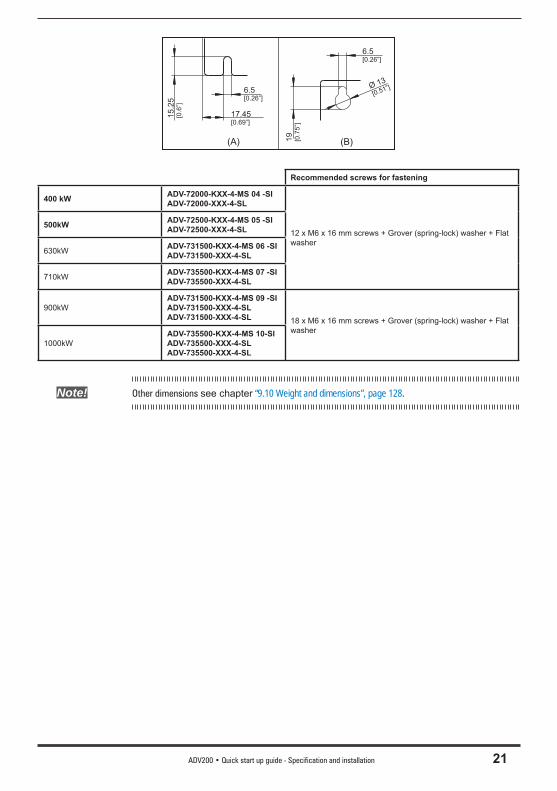
(B)(A)
6.5[0.26”]
6.5[0.26”]
Ø 13
[0.51”]
19
[0.7
5”]
17.45[0.69”]
15.2
5[0
.6”]
Recommended screws for fastening
400 kW ADV-72000-KXX-4-MS 04 -SIADV-72000-XXX-4-SL
12 x M6 x 16 mm screws + Grover (spring-lock) washer + Flat washer
500kW ADV-72500-KXX-4-MS 05 -SIADV-72500-XXX-4-SL
630kW ADV-731500-KXX-4-MS 06 -SIADV-731500-XXX-4-SL
710kW ADV-735500-KXX-4-MS 07 -SIADV-735500-XXX-4-SL
900kWADV-731500-KXX-4-MS 09 -SIADV-731500-XXX-4-SLADV-731500-XXX-4-SL 18 x M6 x 16 mm screws + Grover (spring-lock) washer + Flat
washer1000kW
ADV-735500-KXX-4-MS 10-SIADV-735500-XXX-4-SLADV-735500-XXX-4-SL
Note! Other dimensions see chapter “9.10 Weight and dimensions”, page 128.
22 ADV200 • Quick start up guide - Specification and installation
5 - Wiring Procedure
Adjustable frequency drives are electrical apparatus for use in industrial installations. Parts of the Drives are energized during operation. The electrical installation and the opening of the device should therefore only be carried out by qualifi ed personnel. Im-proper installation of motors or Drives may therefore cause the failure of the device as well as serious injury to persons or material damage. Drive is not equipped with motor overspeed protection logic other than that controlled by software. Follow the instructions given in this manual and observe the local and national safety regulations applicable.
Les drives à fréquence variable sont des dispositifs électriques utilisés dans des installations industriels. Une partie des drives sont sous tension pendant l’operation. L’installation élec-trique et l’ouverture des drives devrait être executé uniquement par du personel qualifi é. De mauvaises installations de moteurs ou de drives peuvent provoquer des dommages materiels ou blesser des personnes. On doit suivir les instructions donneés dans ce manuel et observer les régles nationales de sécurité.
Replace all covers before applying power to the Drive. Failure to do so may result in death or serious injury.
Remettre tous les capots avant de mettre sous tension le drive. Des erreurs peuvent provo-quer de sérieux accidents ou même la mort.
The drive must always be grounded. If the drive is not connected correctly to ground, extremely hazardous conditions may be generated that may result in death or serious injury.Le drive doit toujours être raccordé au système de mise à la terre. Un mauvais raccorde-ment du drive au système de mise à la terre peut se traduire par des conditions extrêmement dangereuses susceptibles d’entraîner le décès ou de graves lésions corporelles.
Never open the device or covers while the AC Input power supply is switched on. Minimum time to wait before working on the terminals or inside the device is listed in section 9.8.Ne jamais ouvrir l’appareil lorsqu’il est suns tension. Le temps minimum d’attente avant de pou-voir travailler sur les bornes ou bien à l’intérieur de l’appareil est indiqué dans la section 9.8.
Do not touch or damage any components when handling the device. The changing of the isolation gaps or the removing of the isolation and covers is not permissible.Manipuler l’appareil de façon à ne pas toucher ou endommager des parties. Il n’est pas permis de changer les distances d’isolement ou bien d’enlever des matériaux isolants ou des capots.
Do not connect power supply voltage that exceeds the standard specifi cation voltage fl uctuation permissible. If excessive voltage is applied to the Drive, damage to the internal components will result.Ne pas raccorder de tension d’alimentation dépassant la fl uctuation de tension permise par les normes. Dans le cas d’ une alimentation en tension excessive, des composants internes peuvent être endommagés.
Operation with Residual Current DeviceIf an RCD (also referred to as ELCB or RCCB) is fi tted, the inverters will operate without nuisance tripping, provided that:- a type B RCD is used.- the trip limit of the RCD is 300mA.- the neutral of the supply is grounded (TT or TN systems)- only one inverter is supplied from each RCD.
Warning!
Caution
ADV200 • Quick start up guide - Specification and installation 23
- the output cables are less than 50m (screened) or 100m (unscreened).
RCD: Residual Current Device RCCB: Residual Current Circuit BreakerELCB: Earth Leakage Circuit Breaker
Note: The residual current operated circuit-breakers used must provide protection against direct-current components in the fault current and must be suitable for briefl y suppressing power pulse current peaks. It is recommended to protect the frequency inverter by fuse separately.
The regulations of the individual country (e.g. VDE regulations in Germany) and the regional power suppliers must be observed!
Fonctionnement avec un dispositif de courant résiduelEn cas d’installation d’un RCD – dispositif de courant résiduel – (également dénommé RCCB ou ELCB), les onduleurs fonctionneront sans faux arrêt à condition que :- le RCD utilisé soit de type B- le seuil de déclenchement du RCD soit fi xé à 300 mA- le neutre du bloc d’alimentation soit mis à la terre (systèmes TT ou TN)- chaque RCD n’alimente qu’un seul onduleur- la longueur des câbles de sortie soit inférieure à 50 m (blindés) ou 100 m (non blindés)
RCD: Dispositif de courant résiduelRCCB: Disjoncteur à courant résiduelELCB: Disjoncteur contre fuite à la terre
Remarque : Les RCD utilisés doivent assurer la protection contre les composants à courant continu présents dans le courant de défaut et doivent être capables de suppri-mer des crêtes de courant en peu de temps. Il est recommandé de protéger séparément l’onduleur au moyen de fusibles.
Respecter la réglementation des pays concernés (par exemple, les normes VDR en Allemagne) et des fournisseurs locaux d’énergie électrique.
Functioning of the Drive without a ground connection is not permitted. To avoid distur-bances, the armature of the motor must be grounded using a separate ground connec-tor from those of other appliances.Défense de faire fonctionner le drive sans qu’il y ait eu raccordement de mise à la terre préa-lable. Pour éviter les perturbations, la carcasse du moteur doit être mise à la terre à l’aide d’un raccord de mise à la masse séparé de ceux des autres appareils.
The grounding connector shall be sized in accordance with the NEC or Canadian Elec-trical Code. The connection shall be made by a UL listed or CSA certifi ed closed-loop terminal connector sized for the wire gauge involved. The connector is to be fi xed using the crimp tool specifi ed by the connector manufacturer.Le raccordement devrait être fait par un connecteur certifi é et mentionné à boucle fermé par lesnormes CSA et UL et dimensionné pour l’épaisseur du cable correspondant. Le connecteur doit êtrefi xé a l’aide d’un instrument de serrage specifi é par le producteur du connecteur.
Do not perform a megger test between the Drive terminals or on the control circuit terminals.Ne pas exécuter un test megger entre les bornes du drive ou entre les bornes du circuit de contrôle.
No voltage should be connected to the output of the drive (terminals U2, V2 W2). The parallel connection of several drives via the outputs and the direct connection of the inputs and outputs (bypass) are not permissible.Aucune tension ne doit être appliquée sur la sortie du convertisseur (bornes U2, V2 et W2). Il n’est pas permis de raccorder la sortie de plusieurs convertisseurs en parallèle, ni d’effectuer
Caution
24 ADV200 • Quick start up guide - Specification and installation
une connexion directede l’entrée avec la sortie du convertisseur (Bypass).
The electrical commissioning should only be carried out by qualifi ed personnel, who are also responsible for the provision of a suitable ground connection and a protected power supply feeder in accordance with the local and national regulations. The motor must be protected against overloads.La mise en service électrique doit être effectuée par un personnel qualifi é. Ce dernier est responsable del’existence d’une connexion de terre adéquate et d’une protection des câbles d’alimentation selon les prescriptions locales et nationales. Le moteur doit être protégé contre la surcharge
If the Drives have been stored for longer than two years, the operation of the DC link capacitors may be impaired and must be “reformed”. Before commissioning devices that have been stored for long periods, connect them to a power supply for two hours with no load connected in order to regenerate the capacitors, (the input voltage has to be applied without enabling the drive).En cas de stockage des variateurs pendant plus de deux ans, il est conseillé de contrôler l’état des condensateurs CC avant d’en effectuer le branchement. Avant la mise en service des appareils, ayant été stockés pendant long temps, il faut alimenter variateurs à vide pen-dant deux heures, pour régénérer les condensateurs : appliquer une tension d’alimentation sans actionner le variateur.
ADV200 • Quick start up guide - Specification and installation 25
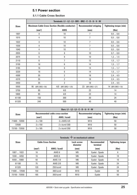
5.1 Power section 5.1.1 Cable Cross Section
Sizes
Terminals: L1 - L2 - L3 - BR1 - BR2 - C - D - U - V - W
Maximum Cable Cross Section (flexible conductor) Recommended stripping Tightening torque (min)
(mm2) AWG (mm) (Nm)
1007 4 10 7 0,5 ... 0,6
1015 4 10 7 0,5 ... 0,6
1022 4 10 7 0,5 ... 0,6
1030 4 10 7 0,5 ... 0,6
1040 4 10 7 0,5 ... 0,6
2055 6 8 10 0,7 ... 0,8
2075 6 8 10 1,2 ... 1,5
2110 6 7 12 1,5 ... 1,7
3150 16 6 14 1,5 ... 1,7
3185 16 6 14 1,5 ... 1,7
3220 16 6 14 1,5 ... 1,7
4300 35 2 18 2,4 ... 4,5
4370 35 2 18 2,4 ... 4,5
4450 35 2 18 2,4 ... 4,5
5550 95 (BR1/BR2=50) 4/0 (BR1/BR2=1/0) 23 (BR1/BR2=27) 14 (BR1/BR2=10)
5750 95 4/0 23 14
5900 95 4/0 23 14
61100 150 300 30 24
61320 240 500 40 40
Sizes
Bars: L1 - L2 - L3 - C - D - U - V - W
Recommended cable cross-section Recommended stripping Tightening torque (min)
(mm2) AWG / kcmil (mm) (Nm)
71600 - 72000 2 x 100 2 x AWG 4/0 M10 50
72500 2 x 150 2 x kcmil 300 M10 50
73150 - 73550 2 x 185 2 x kcmil 350 M10 50
Sizes
Terminals: on mechanical cabinet
Cable Cross Section Lock screw diameter
Recommended terminal
Tightening torque
(mm2) AWG / kcmil (mm) (mm) (Nm)
1007 ... 1022 16 AWG 6 M5 Eyelet - Spade 6
1030 ... 4450 16 AWG 6 M6 Eyelet - Spade 10
5550 ... 5900 50 AWG 1/0 M6 Eyelet - Spade 10
61100 75 AWG 2/0 M8 Eyelet - Spade 24
61320 120 250 kcmil M8 Eyelet - Spade 24
71600 ... 72500 150 300 kcmil M10 Eyelet 50
73150 - 73550 185 350 kcmil M10 Eyelet 50
26 ADV200 • Quick start up guide - Specification and installation
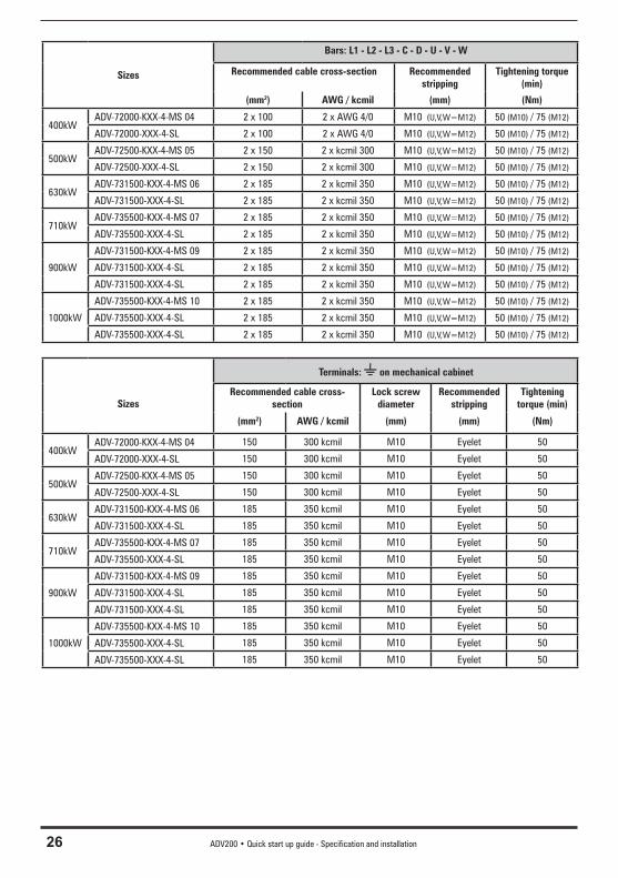
Sizes
Bars: L1 - L2 - L3 - C - D - U - V - W
Recommended cable cross-section Recommended stripping
Tightening torque (min)
(mm2) AWG / kcmil (mm) (Nm)
400kWADV-72000-KXX-4-MS 04 2 x 100 2 x AWG 4/0 M10 (U,V,W=M12) 50 (M10) / 75 (M12)
ADV-72000-XXX-4-SL 2 x 100 2 x AWG 4/0 M10 (U,V,W=M12) 50 (M10) / 75 (M12)
500kWADV-72500-KXX-4-MS 05 2 x 150 2 x kcmil 300 M10 (U,V,W=M12) 50 (M10) / 75 (M12)
ADV-72500-XXX-4-SL 2 x 150 2 x kcmil 300 M10 (U,V,W=M12) 50 (M10) / 75 (M12)
630kWADV-731500-KXX-4-MS 06 2 x 185 2 x kcmil 350 M10 (U,V,W=M12) 50 (M10) / 75 (M12)
ADV-731500-XXX-4-SL 2 x 185 2 x kcmil 350 M10 (U,V,W=M12) 50 (M10) / 75 (M12)
710kWADV-735500-KXX-4-MS 07 2 x 185 2 x kcmil 350 M10 (U,V,W=M12) 50 (M10) / 75 (M12)
ADV-735500-XXX-4-SL 2 x 185 2 x kcmil 350 M10 (U,V,W=M12) 50 (M10) / 75 (M12)
900kW
ADV-731500-KXX-4-MS 09 2 x 185 2 x kcmil 350 M10 (U,V,W=M12) 50 (M10) / 75 (M12)
ADV-731500-XXX-4-SL 2 x 185 2 x kcmil 350 M10 (U,V,W=M12) 50 (M10) / 75 (M12)
ADV-731500-XXX-4-SL 2 x 185 2 x kcmil 350 M10 (U,V,W=M12) 50 (M10) / 75 (M12)
1000kW
ADV-735500-KXX-4-MS 10 2 x 185 2 x kcmil 350 M10 (U,V,W=M12) 50 (M10) / 75 (M12)
ADV-735500-XXX-4-SL 2 x 185 2 x kcmil 350 M10 (U,V,W=M12) 50 (M10) / 75 (M12)
ADV-735500-XXX-4-SL 2 x 185 2 x kcmil 350 M10 (U,V,W=M12) 50 (M10) / 75 (M12)
Sizes
Terminals: on mechanical cabinet
Recommended cable cross-section
Lock screw diameter
Recommended stripping
Tightening torque (min)
(mm2) AWG / kcmil (mm) (mm) (Nm)
400kWADV-72000-KXX-4-MS 04 150 300 kcmil M10 Eyelet 50
ADV-72000-XXX-4-SL 150 300 kcmil M10 Eyelet 50
500kWADV-72500-KXX-4-MS 05 150 300 kcmil M10 Eyelet 50
ADV-72500-XXX-4-SL 150 300 kcmil M10 Eyelet 50
630kWADV-731500-KXX-4-MS 06 185 350 kcmil M10 Eyelet 50
ADV-731500-XXX-4-SL 185 350 kcmil M10 Eyelet 50
710kWADV-735500-KXX-4-MS 07 185 350 kcmil M10 Eyelet 50
ADV-735500-XXX-4-SL 185 350 kcmil M10 Eyelet 50
900kW
ADV-731500-KXX-4-MS 09 185 350 kcmil M10 Eyelet 50
ADV-731500-XXX-4-SL 185 350 kcmil M10 Eyelet 50
ADV-731500-XXX-4-SL 185 350 kcmil M10 Eyelet 50
1000kW
ADV-735500-KXX-4-MS 10 185 350 kcmil M10 Eyelet 50
ADV-735500-XXX-4-SL 185 350 kcmil M10 Eyelet 50
ADV-735500-XXX-4-SL 185 350 kcmil M10 Eyelet 50
ADV200 • Quick start up guide - Specification and installation 27
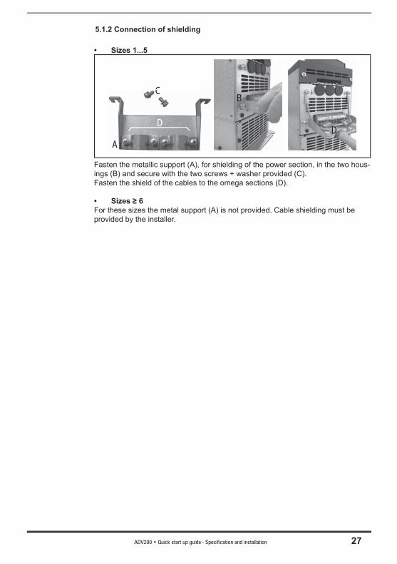
5.1.2 Connection of shielding
• Sizes 1...5
A
C
A
CCB
DD
Fasten the metallic support (A), for shielding of the power section, in the two hous-ings (B) and secure with the two screws + washer provided (C). Fasten the shield of the cables to the omega sections (D).
• Sizes ≥ 6For these sizes the metal support (A) is not provided. Cable shielding must be provided by the installer.
28 ADV200 • Quick start up guide - Specification and installation
5.1.3 EMC guide line
Drives are designed to operate in an industrial environment where a high level of electromagnetic interference are to be expected. Proper installation practices will ensure safe and trouble-free operation. If you encounter problems, follow the guidelines which follow.- Check for all equipment in the cabinet are well grounded using short, thick
grounding cable connected to a common star point or busbar. Better solution is to use a conductive mounting plane and use that as EMC ground reference plane.
- Flat conductors, for EMC grounding, are better than other type because they have lower impedance at higher frequencies.
- Make sure that any control equipment (such as a PLC) connected to the inverter is connected to the same EMC ground or star point as the inverter via a short thick link.
- Connect the return ground from the motors controlled by the drives directly to the ground connection ( ) on the associated inverter.
- Separate the control cables from the power cables as much as possible, using separate trunking, if necessary at 90º to each other.
- Whenever possible, use screened leads for the connections to the control circuitry.
- Ensure that the contactors in the cubicle are suppressed, either with R-C suppressors for AC contactors or ‘fl ywheel’ diodes for DC contactors fi tted to the coils. Varistor suppressors are also effective. This is important when the contactors are controlled from the inverter relay .
- Use screened or armored cables for the motor connections and ground the screen at both ends using the cable clamps.
Note! For further information regarding electro-magnetic compatibility standards, according to Directive 89/336/EEC, conformity checks carried out on Gefran appliances, connection of filters and mains inductors, shielding of cables, ground connections, etc., consult the “Electro-magnetic compatibility guide” on the CD attached to this drive.
Attention
ADV200 • Quick start up guide - Specification and installation 29
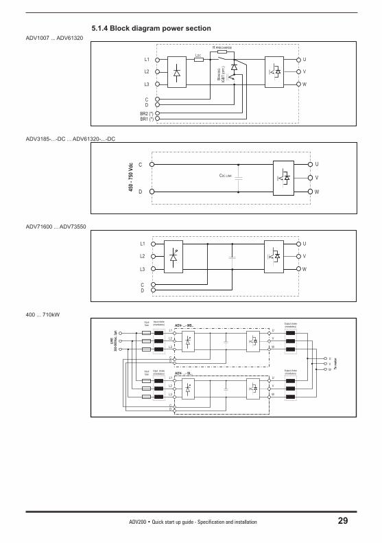
5.1.4 Block diagram power sectionADV1007 ... ADV61320
L1
L2
L3
CD
BR2 (*)BR1 (*)
LDC
U
V
W
R PRECHARGE
BR
AK
ING
IGB
T(O
PT.)
ADV3185-...-DC ... ADV61320-...-DC
C
D
U
V
W
CDC LINK
450
- 75
0 V
dc
ADV71600 ... ADV73550
L1
L2
L3
CD
U
V
W
400 ... 710kW
L1
L2
L3
CD
U
V
W
ADV- ...- MS..
L1
L2
L3
CD
U
V
W
LIN
E38
0-50
0Vac
, 3p
h
Inputfuse
Input choke(mandatory)
Inputfuse
Input choke(mandatory) ADV- ...- SL..
Output choke(mandatory)
Output choke(mandatory)
U
V
W Tom
oto
r
30 ADV200 • Quick start up guide - Specification and installation
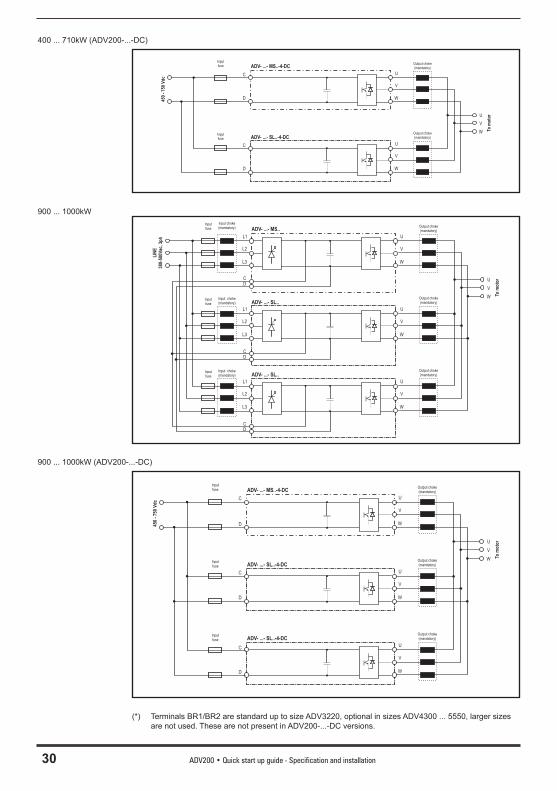
400 ... 710kW (ADV200-...-DC)
C
D
U
V
W
ADV- ...- MS..-4-DC
C
D
U
V
W
450
- 75
0 V
dc
Inputfuse
Inputfuse ADV- ...- SL..-4-DC
Output choke(mandatory)
Output choke(mandatory)
U
V
W To m
oto
r
900 ... 1000kW
L1
L2
L3
CD
U
V
W
ADV- ...- MS..
L1
L2
L3
CD
U
V
W
LIN
E38
0-50
0Vac
, 3p
h
Inputfuse
Input choke(mandatory)
Inputfuse
Input choke(mandatory) ADV- ...- SL..
Output choke(mandatory)
Output choke(mandatory)
U
V
W Tom
oto
r
L1
L2
L3
CD
U
V
W
Inputfuse
Input choke(mandatory) ADV- ...- SL..
Output choke(mandatory)
900 ... 1000kW (ADV200-...-DC)
C
D
U
V
W
ADV- ...- MS..-4-DC
C
D
U
V
W
Inputfuse
Inputfuse ADV- ...- SL..-4-DC
Output choke(mandatory)
Output choke(mandatory)
U
V
W To m
oto
r
C
D
U
V
W
Inputfuse ADV- ...- SL..-4-DC
Output choke(mandatory)
450
- 75
0 V
dc
(*) Terminals BR1/BR2 are standard up to size ADV3220, optional in sizes ADV4300 ... 5550, larger sizes are not used. These are not present in ADV200-...-DC versions.

ADV200 • Quick start up guide - Specification and installation 31
5.1.5 Internal EMC fi lterADV200 series inverters are equipped with an internal EMI (except ADV200-...-DC models) fi lter able to guarantee the performance levels required by EN 61800-3 standard (according to 2nd environment, category C3) with a maximum of 20 meters of shielded motor cable (up to 50 metres for size 5 and above).
32 ADV200 • Quick start up guide - Specification and installation
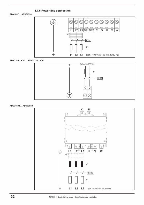
5.1.6 Power line connectionADV1007 ... ADV61320
L1 L2 L3 BR1 BR2 C D U V W
K1M
L1 L2 L3
F1
( 400 V / 460 50/60 Hz)AC3ph - VAC,
ADV3185-...-DC ... ADV61320-...-DC
C D
K1M
F1
DC - 450/750 VDC
ADV71600 ... ADV73550
C D
L1 L2 L3 U V W
K1M
L1 L2 L3
F1
( 400 V / 460 50/60 Hz)AC3ph - VAC,
L1
ADV200 • Quick start up guide - Specification and installation 33
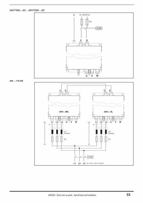
ADV71600-...-DC ... ADV73550-...-DC
C D
U V W
K1M
F1
DC - 450/750 VDC
400 ... 710 kW
C D
L1 L2 L3 U V W
F1
( 400 V / 460 50/60 Hz)AC3ph - VAC,
L1Mandatory
C D
L1 L2 L3 U V W
K1M
L1 L2 L3
F1
ADV-...-MS.. ADV-...-SL
L1Mandatory
34 ADV200 • Quick start up guide - Specification and installation
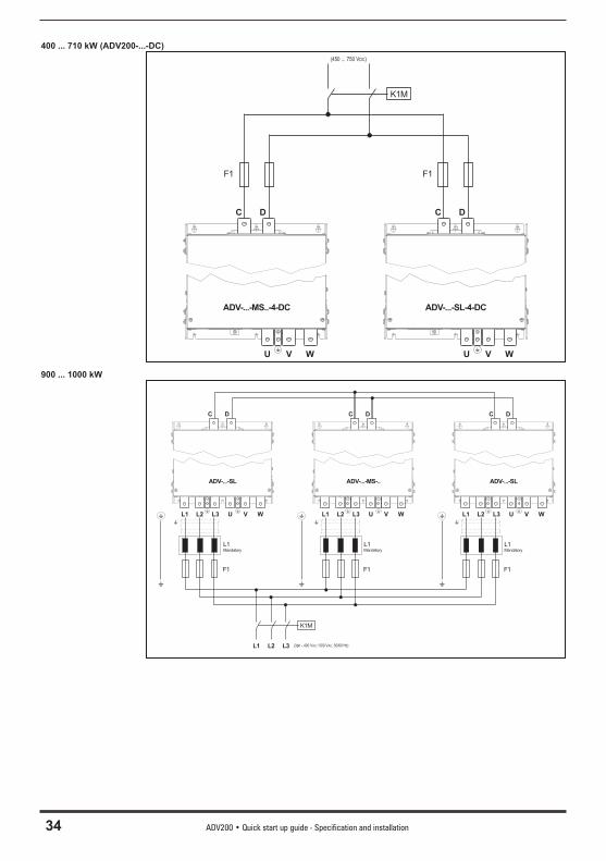
400 ... 710 kW (ADV200-...-DC)
C D
U V W
C D
U V W
ADV-...-MS..-4-DC ADV-...-SL-4-DC
(450 ... 750 )VDC
K1M
F1F1
900 ... 1000 kW
C D
L1 L2 L3 U V W
F1
( 400 V / 500 50/60 Hz)AC3ph - VAC,
L1Mandatory
C D
L1 L2 L3 U V W
K1M
L1 L2 L3
F1
ADV-...-MS-..ADV-...-SL
L1Mandatory
C D
L1 L2 L3 U V W
F1
ADV-...-SL
L1Mandatory
ADV200 • Quick start up guide - Specification and installation 35
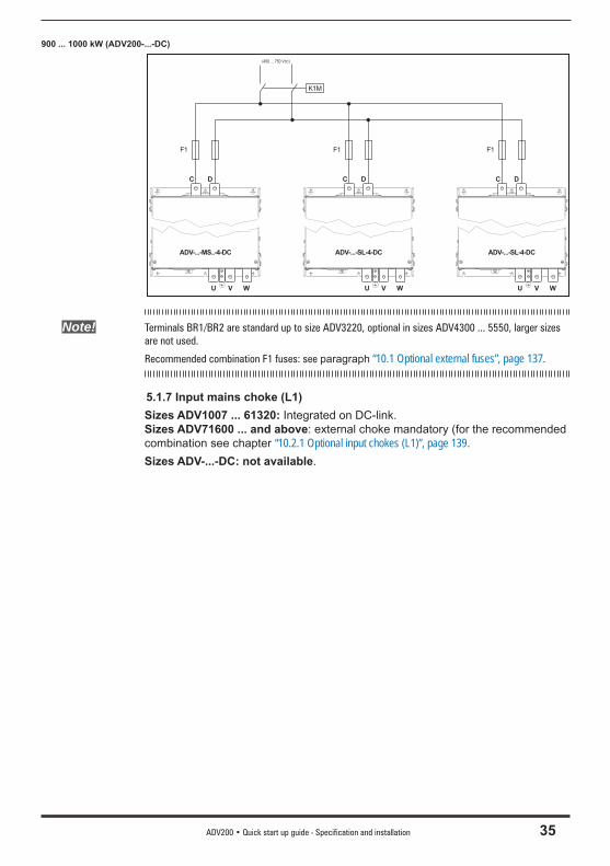
900 ... 1000 kW (ADV200-...-DC)
C D
U V W
ADV-...-MS..-4-DC
C D
U V W
ADV-...-SL-4-DC
(450 ... 750 V )DC
K1M
F1F1
C D
U V W
ADV-...-SL-4-DC
F1
Note! Terminals BR1/BR2 are standard up to size ADV3220, optional in sizes ADV4300 ... 5550, larger sizes are not used.
Recommended combination F1 fuses: see paragraph “10.1 Optional external fuses”, page 137.
5.1.7 Input mains choke (L1)Sizes ADV1007 ... 61320: Integrated on DC-link.Sizes ADV71600 ... and above: external choke mandatory (for the recommended combination see chapter “10.2.1 Optional input chokes (L1)”, page 139.Sizes ADV-...-DC: not available.

36 ADV200 • Quick start up guide - Specification and installation
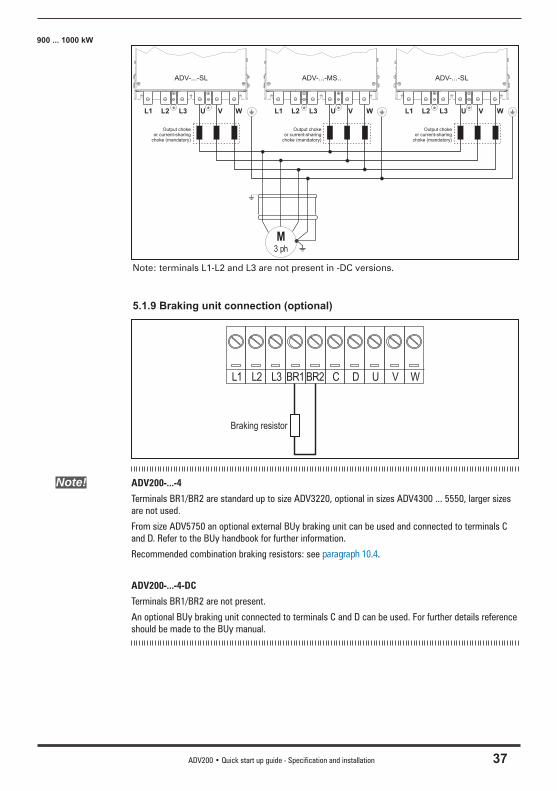
5.1.8 Motor connectionADV1007 ... ADV61320
M3 ph
L1 L2 L3 BR1 BR2 C D U V W
Note: terminals L1-L2 and L3 are not present in -DC versions.
ADV71600 ... ADV73550
L1 L2 L3 U V W
M3 ph
Note: terminals L1-L2 and L3 are not present in -DC versions.
400 ... 710 kW
L1 L2 L3 U V W
M3 ph
L1 L2 L3 U V W
ADV-...-MS-.. ADV-...-SL
Output chokeor current-sharing
choke (mandatory)
Output chokeor current-sharing
choke (mandatory)
Note: terminals L1-L2 and L3 are not present in -DC versions.
ADV200 • Quick start up guide - Specification and installation 37
900 ... 1000 kW
L1 L2 L3 U V W
M3 ph
L1 L2 L3 U V W
ADV-...-MS..ADV-...-SL
L1 L2 L3 U V W
ADV-...-SL
Output chokeor current-sharing
choke (mandatory)
Output chokeor current-sharing
choke (mandatory)
Output chokeor current-sharing
choke (mandatory)
Note: terminals L1-L2 and L3 are not present in -DC versions.
5.1.9 Braking unit connection (optional)
L1 L2 L3 BR1 BR2 C D U V W
Braking resistor
Note! ADV200-...-4
Terminals BR1/BR2 are standard up to size ADV3220, optional in sizes ADV4300 ... 5550, larger sizes are not used.
From size ADV5750 an optional external BUy braking unit can be used and connected to terminals C and D. Refer to the BUy handbook for further information.
Recommended combination braking resistors: see paragraph 10.4.
ADV200-...-4-DC
Terminals BR1/BR2 are not present.
An optional BUy braking unit connected to terminals C and D can be used. For further details reference should be made to the BUy manual.
38 ADV200 • Quick start up guide - Specification and installation
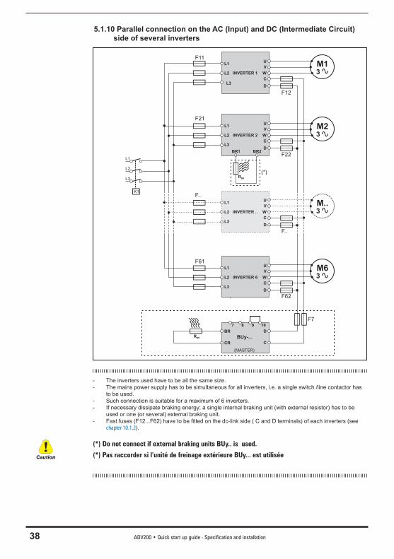
5.1.10 Parallel connection on the AC (Input) and DC (Intermediate Circuit) side of several inverters
M13
M23
M63
F11
F21
F61
L1
L2
L3
U
V
W
C
D
INVERTER 1
L1
L2
L3
U
V
W
C
D
INVERTER 2
BR1
F12
F22
F62
L1
L2
L3
U
V
W
C
D
INVERTER 6
BR
CR C
D
B y-...U
(MASTER)
7 8 9 10
RBR
F7
RBR
L1
L2
L3
K1
M..3
F..
L1
L2
L3
U
V
W
C
D
INVERTER ..
F..
(*)
BR2
- The inverters used have to be all the same size.- The mains power supply has to be simultaneous for all inverters, i.e. a single switch /line contactor has
to be used.- Such connection is suitable for a maximum of 6 inverters.- If necessary dissipate braking energy; a single internal braking unit (with external resistor) has to be
used or one (or several) external braking unit.- Fast fuses (F12...F62) have to be fi tted on the dc-link side ( C and D terminals) of each inverters (see
chapter 10.1.2).
(*) Do not connect if external braking units BUy.. is used.
(*) Pas raccorder si l’unité de freinage extérieure BUy... est utiliséeCaution
ADV200 • Quick start up guide - Specification and installation 39
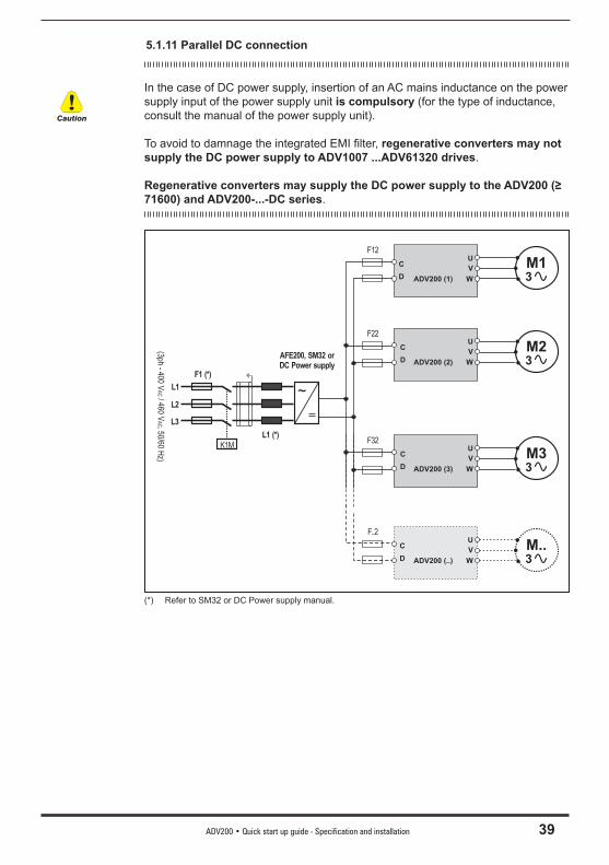
5.1.11 Parallel DC connection
In the case of DC power supply, insertion of an AC mains inductance on the power supply input of the power supply unit is compulsory (for the type of inductance, consult the manual of the power supply unit).
To avoid to damnage the integrated EMI fi lter, regenerative converters may not supply the DC power supply to ADV1007 ...ADV61320 drives.
Regenerative converters may supply the DC power supply to the ADV200 (≥ 71600) and ADV200-...-DC series.
M13
M23
U
V
W
C
D ADV200 (1)
U
V
W
C
D ADV200 (2)
M..3
U
V
W
C
D ADV200 (..)
K1M
L1
L2
L3
F1 (*)
(400 V
/ 46050/60 H
z)A
C3ph -
VA
C,
L1 (*)
F12
F22
F..2
M33
U
V
W
C
D ADV200 (3)
F32
AFE200, SM32 orDC Power supply
(*) Refer to SM32 or DC Power supply manual.
Caution
40 ADV200 • Quick start up guide - Specification and installation
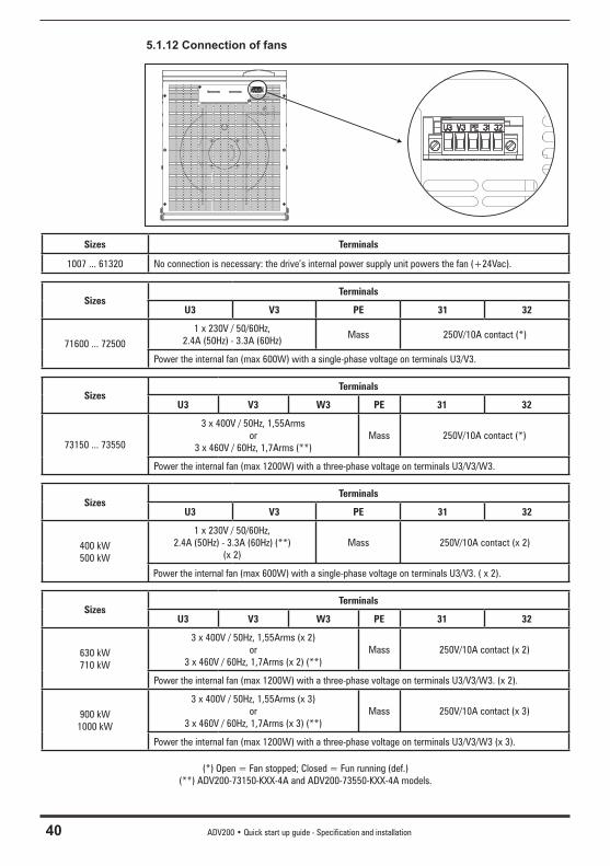
5.1.12 Connection of fans
Sizes Terminals
1007 ... 61320 No connection is necessary: the drive’s internal power supply unit powers the fan (+24Vac).
Sizes Terminals
U3 V3 PE 31 32
71600 ... 72500
1 x 230V / 50/60Hz, 2.4A (50Hz) - 3.3A (60Hz)
Mass 250V/10A contact (*)
Power the internal fan (max 600W) with a single-phase voltage on terminals U3/V3.
Sizes Terminals
U3 V3 W3 PE 31 32
73150 ... 73550
3 x 400V / 50Hz, 1,55Armsor
3 x 460V / 60Hz, 1,7Arms (**)Mass 250V/10A contact (*)
Power the internal fan (max 1200W) with a three-phase voltage on terminals U3/V3/W3.
SizesTerminals
U3 V3 PE 31 32
400 kW500 kW
1 x 230V / 50/60Hz,2.4A (50Hz) - 3.3A (60Hz) (**)
(x 2)Mass 250V/10A contact (x 2)
Power the internal fan (max 600W) with a single-phase voltage on terminals U3/V3. ( x 2).
SizesTerminals
U3 V3 W3 PE 31 32
630 kW710 kW
3 x 400V / 50Hz, 1,55Arms (x 2)or
3 x 460V / 60Hz, 1,7Arms (x 2) (**)Mass 250V/10A contact (x 2)
Power the internal fan (max 1200W) with a three-phase voltage on terminals U3/V3/W3. (x 2).
900 kW1000 kW
3 x 400V / 50Hz, 1,55Arms (x 3)or
3 x 460V / 60Hz, 1,7Arms (x 3) (**)Mass 250V/10A contact (x 3)
Power the internal fan (max 1200W) with a three-phase voltage on terminals U3/V3/W3 (x 3).
(*) Open = Fan stopped; Closed = Fun running (def.)(**) ADV200-73150-KXX-4A and ADV200-73550-KXX-4A models.

ADV200 • Quick start up guide - Specification and installation 41
Make sure the sequence of the three-phase fan power supply phases is the same as that shown on the relative drive terminals. If not, the air flow will be inadequate to ensure correct cooling..
Caution
42 ADV200 • Quick start up guide - Specification and installation
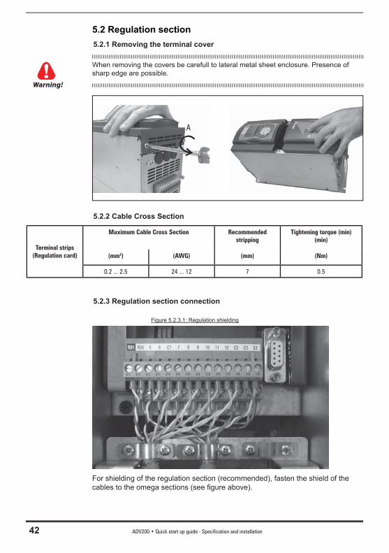
5.2 Regulation section 5.2.1 Removing the terminal cover
When removing the covers be carefull to lateral metal sheet enclosure. Presence of sharp edge are possible.
AA
5.2.2 Cable Cross Section
Terminal strips(Regulation card)
Maximum Cable Cross Section Recommended stripping
Tightening torque (min) (min)
(mm2) (AWG) (mm) (Nm)
0.2 ... 2.5 24 ... 12 7 0.5
5.2.3 Regulation section connection
Figure 5.2.3.1: Regulation shielding
For shielding of the regulation section (recommended), fasten the shield of the cables to the omega sections (see fi gure above).
Warning!
ADV200 • Quick start up guide - Specification and installation 43
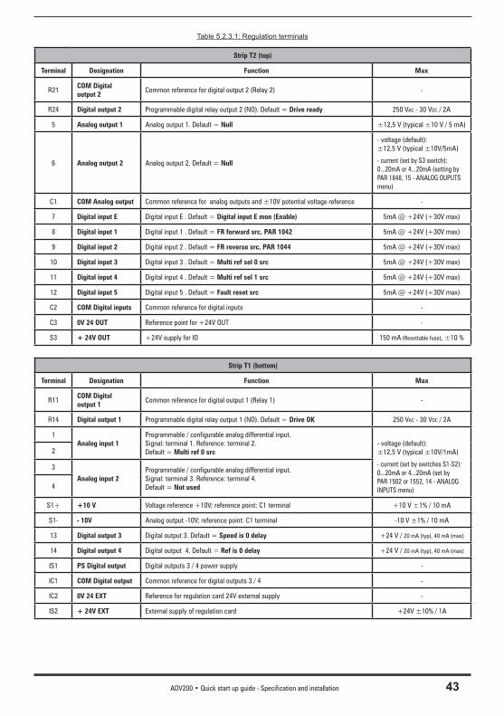
Table 5.2.3.1: Regulation terminals
Strip T2 (top)
Terminal Designation Function Max
R21COM Digital output 2
Common reference for digital output 2 (Relay 2) -
R24 Digital output 2 Programmable digital relay output 2 (NO). Default = Drive ready 250 VAC - 30 VDC / 2A
5 Analog output 1 Analog output 1. Default = Null ±12,5 V (typical ±10 V / 5 mA)
6 Analog output 2 Analog output 2. Default = Null
- voltage (default): ±12,5 V (typical ±10V/5mA)
- current (set by S3 switch): 0...20mA or 4...20mA (setting by PAR 1848, 15 - ANALOG OUPUTS menu)
C1 COM Analog output Common reference for analog outputs and ±10V potential voltage reference -
7 Digital input E Digital input E . Default = Digital input E mon (Enable) 5mA @ +24V (+30V max)
8 Digital input 1 Digital input 1 . Default = FR forward src, PAR 1042 5mA @ +24V (+30V max)
9 Digital input 2 Digital input 2 . Default = FR reverse src, PAR 1044 5mA @ +24V (+30V max)
10 Digital input 3 Digital input 3 . Default = Multi ref sel 0 src 5mA @ +24V (+30V max)
11 Digital input 4 Digital input 4 . Default = Multi ref sel 1 src 5mA @ +24V (+30V max)
12 Digital input 5 Digital input 5 . Default = Fault reset src 5mA @ +24V (+30V max)
C2 COM Digital inputs Common reference for digital inputs -
C3 0V 24 OUT Reference point for +24V OUT -
S3 + 24V OUT +24V supply for IO 150 mA (Resettable fuse), ±10 %
Strip T1 (bottom)
Terminal Designation Function Max
R11COM Digital output 1
Common reference for digital output 1 (Relay 1) -
R14 Digital output 1 Programmable digital relay output 1 (NO). Default = Drive OK 250 VAC - 30 VDC / 2A
1Analog input 1
Programmable / configurable analog differential input.Signal: terminal 1. Reference: terminal 2. Default = Multi ref 0 src
- voltage (default): ±12,5 V (typical ±10V/1mA)
- current (set by switches S1-S2): 0...20mA or 4...20mA (set by PAR 1502 or 1552, 14 - ANALOG INPUTS menu)
2
3
Analog input 2Programmable / configurable analog differential input.Signal: terminal 3. Reference: terminal 4. Default = Not used4
S1+ +10 V Voltage reference +10V; reference point: C1 terminal +10 V ±1% / 10 mA
S1- - 10V Analog output -10V; reference point: C1 terminal -10 V ±1% / 10 mA
13 Digital output 3 Digital output 3. Default = Speed is 0 delay +24 V / 20 mA (typ), 40 mA (max)
14 Digital output 4 Digital output 4. Default = Ref is 0 delay +24 V / 20 mA (typ), 40 mA (max)
IS1 PS Digital output Digital outputs 3 / 4 power supply -
IC1 COM Digital output Common reference for digital outputs 3 / 4 -
IC2 0V 24 EXT Reference for regulation card 24V external supply -
IS2 + 24V EXT External supply of regulation card +24V ±10% / 1A
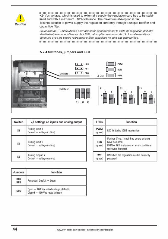
44 ADV200 • Quick start up guide - Specification and installation
+24VDC voltage, which is used to externally supply the regulation card has to be stabi-lized and with a maximum ±10% tolerance. The maximum absorption is 1A. It is not suitable to power supply the regulation card only through a unique rectifi er and capacitive fi lter.La tension de + 24Vdc utilisée pour alimenter extérieurement la carte de régulation doit être stabiliséeet avec une tolérance de ±10% ; absorption maximum de 1A. Les alimentations obtenues avec les seules redresseur e fi ltre capacitive ne sont pas appropriées.
5.2.4 Switches, jumpers and LED
LEDs :
S1 S2 S3
PWM
RUN
PWR
Switches : S1
Jumpers :
HC0
HC1
CFG
V IS2
V IS3
V I
Switch V/I settings on inputs and analog output LEDs Function
S1Analog input 1Default = voltage (±10 V)
PWM(green)
LED lit during IGBT modulation
S2Analog input 2Default = voltage (±10 V)
RUN(green)
Flashes (freq. 1 sec) if no errors or faults have occurred. If ON or OFF, indicates an error conditions (software hangup)
S3Analog output 2Default = voltage (±10 V)
PWR(green)
ON when the regulation card is correctly powered
Jumpers Function
HC0HC1
Reserved. Deafult = Open
CFGOpen = 400 Vac rated voltage (default)Closed = 460 Vac rated voltage
Caution
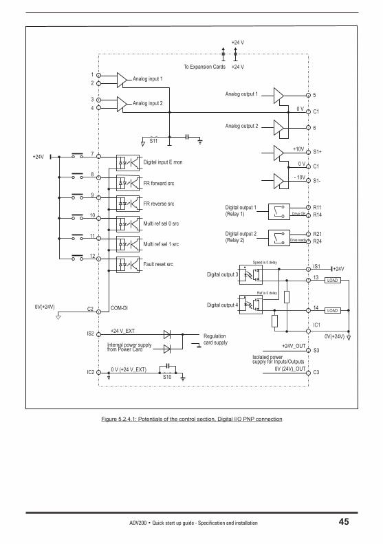
ADV200 • Quick start up guide - Specification and installation 45
1
2
3
4
+24V
8
9
10
11
12
C2
IS2
IC2
Analog input 1
Analog input 2
Digital input E mon
FR forward src
FR reverse src
Multi ref sel 0 src
Multi ref sel 1 src
Fault reset src
Internal power supplyfrom Power Card
COM-DI
+24 V_EXT
0 V (+24 V_EXT)
Analog output 2
5
C10 V
6
S1+
C1
S1-
+10V
- 10V
0 V
R11
R14
R21
R24
Digital output 1(Relay 1)
Digital output 2(Relay 2)
IS1
13
14
Digital output 3
Digital output 4
C3
S3+24V_OUT
0V (24V)_OUT
To Expansion Cards
S11
Analog output 1
0V(+24V)LOAD
+24V
0V(+24V)
LOAD
7
IC1
Drive OK
Drive ready
Speed is 0 delay
Ref is 0 delay
Isolated powersupply for Inputs/Outputs
+24 V
+24 V
Regulationcard supply
S10
Figure 5.2.4.1: Potentials of the control section, Digital I/O PNP connection
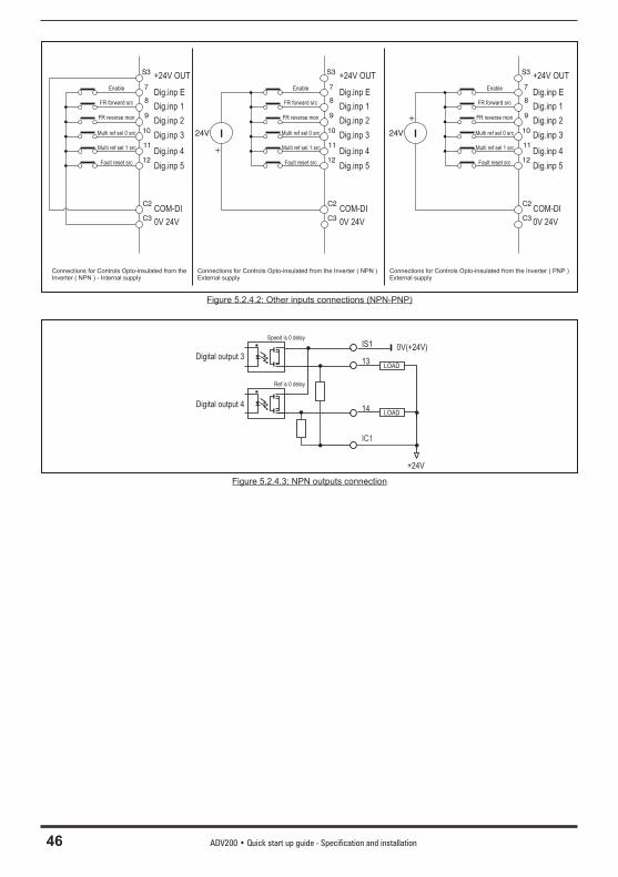
46 ADV200 • Quick start up guide - Specification and installation
S3
9
11
7
12
8
10
C2
C3
FR reverse mon
Enable
FR forward src
Multi ref sel 0 src
Multi ref sel 1 src
Fault reset src
+24V OUT
Dig.inp 3
Dig.inp 1
Dig.inp 2
Dig.inp 4
Dig.inp 5
I
+
24V I
+
24V
COM-DI
0V 24V
+24V OUT
Dig.inp 3
Dig.inp 1
Dig.inp 2
Dig.inp 4
Dig.inp 5
COM-DI
0V 24V
+24V OUT
Dig.inp 3
Dig.inp 1
Dig.inp 2
Dig.inp 4
Dig.inp 5
COM-DI
0V 24V
S3
9
11
7
12
8
10
C2
C3
S3
9
11
7
12
8
10
C2
C3
Dig.inp E Dig.inp E Dig.inp E
Connections for Controls Opto-insulated from theInverter ( NPN ) - Internal supply
Connections for Controls Opto-insulated from the Inverter ( NPN )External supply
Connections for Controls Opto-insulated from the Inverter ( PNP )External supply
FR reverse mon
Enable
FR forward src
Multi ref sel 0 src
Multi ref sel 1 src
Fault reset src
FR reverse mon
Enable
FR forward src
Multi ref sel 0 src
Multi ref sel 1 src
Fault reset src
Figure 5.2.4.2: Other inputs connections (NPN-PNP)
IS1
13
14
Digital output 3
Digital output 4LOAD
+24V
0V(+24V)
LOAD
IC1
Speed is 0 delay
Ref is 0 delay
Figure 5.2.4.3: NPN outputs connection
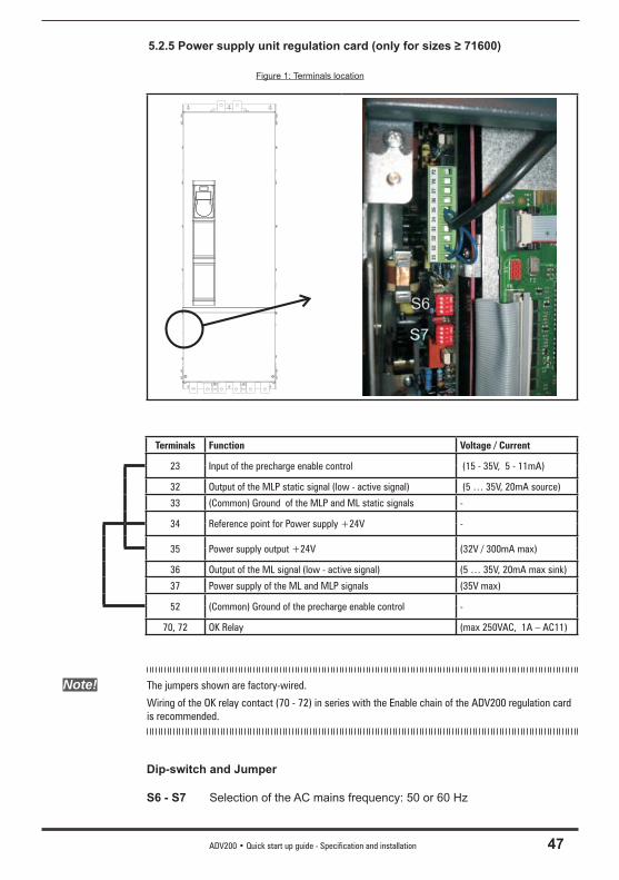
ADV200 • Quick start up guide - Specification and installation 47
5.2.5 Power supply unit regulation card (only for sizes ≥ 71600)
Figure 1: Terminals location
Terminals Function Voltage / Current
23 Input of the precharge enable control (15 - 35V, 5 - 11mA)
32 Output of the MLP static signal (low - active signal) (5 … 35V, 20mA source)
33 (Common) Ground of the MLP and ML static signals -
34 Reference point for Power supply +24V -
35 Power supply output +24V (32V / 300mA max)
36 Output of the ML signal (low - active signal) (5 … 35V, 20mA max sink)
37 Power supply of the ML and MLP signals (35V max)
52 (Common) Ground of the precharge enable control -
70, 72 OK Relay (max 250VAC, 1A – AC11)
Note! The jumpers shown are factory-wired.
Wiring of the OK relay contact (70 - 72) in series with the Enable chain of the ADV200 regulation card is recommended.
Dip-switch and Jumper
S6 - S7 Selection of the AC mains frequency: 50 or 60 Hz
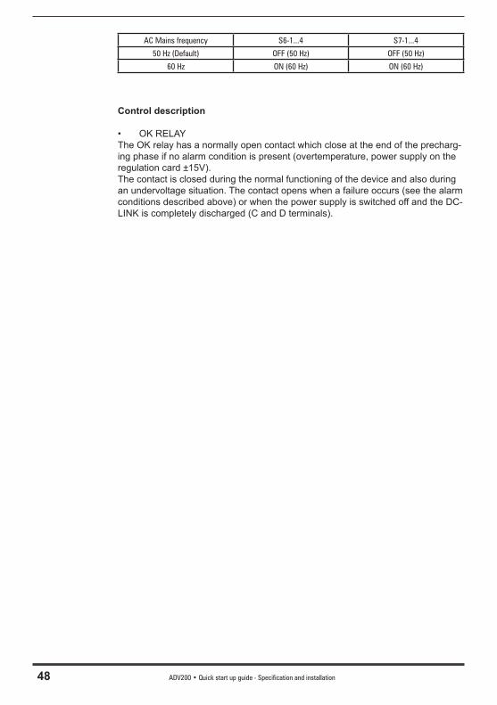
48 ADV200 • Quick start up guide - Specification and installation
AC Mains frequency S6-1...4 S7-1...4
50 Hz (Default) OFF (50 Hz) OFF (50 Hz)
60 Hz ON (60 Hz) ON (60 Hz)
Control description
• OK RELAYThe OK relay has a normally open contact which close at the end of the precharg-ing phase if no alarm condition is present (overtemperature, power supply on the regulation card ±15V).The contact is closed during the normal functioning of the device and also during an undervoltage situation. The contact opens when a failure occurs (see the alarm conditions described above) or when the power supply is switched off and the DC-LINK is completely discharged (C and D terminals).
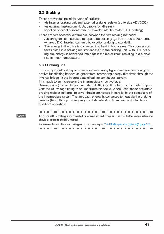
ADV200 • Quick start up guide - Specification and installation 49
5.3 BrakingThere are various possible types of braking:- via internal braking unit and external braking resistor (up to size ADV5550),- via external braking unit (BUy, usable for all sizes),- Injection of direct current from the Inverter into the motor (D.C. braking)There are two essential differences between the two braking methods:- A braking unit can be used for speed reduction (e.g.: from 1000 to 800 rpm),
whereas D.C. braking can only be usedfor braking to standstill.- The energy in the drive is converted into heat in both cases. This conversion
takes place in a braking resistor encased in the braking unit. With D.C. brak-ing, the energy is converted into heat in the motor itself, resulting in a further rise in motor temperature.
5.3.1 Braking unitFrequency-regulated asynchronous motors during hyper-synchronous or regen-erative functioning behave as generators, recovering energy that fl ows through the inverter bridge, in the intermediate circuit as continuous current.This leads to an increase in the intermediate circuit voltage. Braking units (internal to drive or external BUy) are therefore used in order to pre-vent the DC voltage rising to an impermissible value. When used, these activate a braking resistor (external to drive) that is connected in parallel to the capacitors of the intermediate circuit. The feedback energy is converted to heat via the braking resistor (RBR), thus providing very short deceleration times and restricted four-quadrant operation.
Note! An optional BUy braking unit connected to terminals C and D can be used. For further details reference should be made to the BUy manual.
Recommended combination braking resistors: see chapter “10.4 Braking resistor (optional)”, page 146.
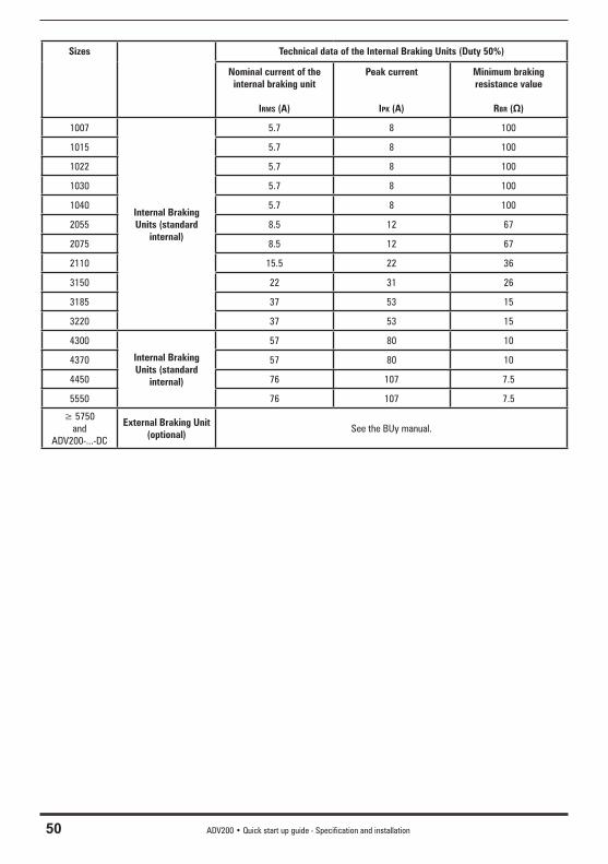
50 ADV200 • Quick start up guide - Specification and installation
Sizes Technical data of the Internal Braking Units (Duty 50%)
Nominal current of the internal braking unit
IRMS (A)
Peak current
IPK (A)
Minimum braking resistance value
RBR (Ω)
1007
Internal Braking Units (standard
internal)
5.7 8 100
1015 5.7 8 100
1022 5.7 8 100
1030 5.7 8 100
1040 5.7 8 100
2055 8.5 12 67
2075 8.5 12 67
2110 15.5 22 36
3150 22 31 26
3185 37 53 15
3220 37 53 15
4300
Internal Braking Units (standard
internal)
57 80 10
4370 57 80 10
4450 76 107 7.5
5550 76 107 7.5
≥ 5750and
ADV200-...-DC
External Braking Unit (optional)
See the BUy manual.
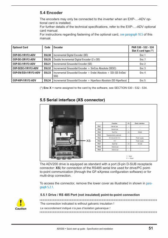
ADV200 • Quick start up guide - Specification and installation 51
5.4 EncoderThe encoders may only be connected to the inverter when an EXP-...-ADV op-tional card is installed.For further details of the technical specifi cations, refer to the EXP-...-ADV optional card manual.For instructions regarding fastening of the optional card, see paragraph 10.5 of this manual.
Optional Card Code Encoder PAR 530 - 532 - 534 Slot X card type (*)
EXP-DE-I1R1F2-ADV S5L30 Incremental Digital Encoder (DE) Enc 1
EXP-DE-I2R1F2-ADV S5L35 Double Incremental Digital Encoder (2 x DE) Enc 7
EXP-SE-I1R1F2-ADV S5L31 Incremental Sinusoidal Encoder (SE) Enc 2
EXP-SESC-I1R1F2-ADV S5L32 Incremental Sinusoidal Encoder + SinCos Absolute (SESC) Enc 3
EXP-EN/SSI-I1R1F2-ADV S5L33 Incremental Sinusoidal Encoder + Endat Absolute + SSI (SE-EnDat/SSI)
Enc 4
EXP-HIP-I1R1F2-ADV S5L34 Incremental Sinusoidal Encoder + Hiperface Absolute (SE-Hiperface) Enc 5
(*) Enc X = name assigned to the card by the software, see SECTION 530 - 532 - 534.
5.5 Serial interface (XS connector)
XS
Function I/O Electr. interface
PIN 1 Internal use – –
PIN 2 Internal use – –
PIN 3 RxA/TxA I/O RS485
PIN 4 Equipotentiality (optional) – –
PIN 5 0V (Ground for 5 V) – Power supply
PIN 6
Internal use
–
–
PIN 7 RxB/TxB I/O RS 485
PIN 8 Internal use – –
PIN 9
+5 V
–
Power supply
I = Input
O = Output
The ADV200 drive is equipped as standard with a port (9-pin D-SUB receptacle connector: XS) for connection of the RS485 serial line used for drive/PC point-to-point communication (through the GF-eXpress confi guration software) or for multi-drop connection.
To access the connector, remove the lower cover as illustrated in shown in para-graph 5.2.1.
5.5.1 Drive / RS 485 Port (not insulated) point-to-point connection
The connection indicated is without galvanic insulation ! Le raccordement indiqué n’a pas d’isolation galvanique ! Caution
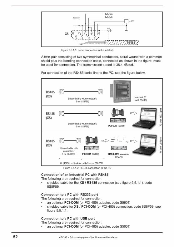
52 ADV200 • Quick start up guide - Specification and installation
12345
9 8 7 6
TxA/RxA
TxB/RxB
PE
+5 V
XS
Reserved
RS485EQP
Figure 5.5.1.1: Serial connection (not insulated)
A twin-pair consisting of two symmetrical conductors, spiral wound with a common shield plus the bonding connection cable, connected as shown in the fi gure, must be used for connection. The transmission speed is 38.4 kBaud.
For connection of the RS485 serial line to the PC, see the fi gure below.
RS485
(XS)
RS485RS232
PCI-COM (S5T60)
Industrial PC
(with RS485)
RS232USB
USB RS232 converter
(S5A20)
PC
wit
hR
S232
port
PC
wit
hU
SB
port
RS485
(XS)
RS485
(XS)RS485
RS232
PCI-COM (S5T60)
Shielded cable with connectors,
5 mt (8S8F59)
Shielded cable with connectors,
5 mt (8S8F59)
Shielded cable with
connectors,
5 mt (8S8F59)
Kit (S50T6) = Shielded cable 5 mt + PCI-COM
Figure 5.5.1.2: RS485 connection to the PC
Connection of an industrial PC with RS485The following are required for connection:• shielded cable for the XS / RS485 connection (see fi gure 5.5.1.1), code
8S8F59
Connection to a PC with RS232 portThe following are required for connection:• an optional PCI-COM (or PCI-485) adapter, code S560T.• shielded cable for XS / PCI-COM (or PCI-485) connection, code 8S8F59, see
fi gure 5.5.1.1 .
Connection to a PC with USB portThe following are required for connection:• an optional PCI-COM (or PCI-485) adapter, code S560T.
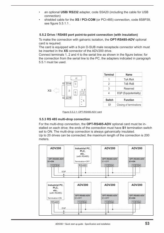
ADV200 • Quick start up guide - Specification and installation 53
• an optional USB/ RS232 adapter, code S5A20 (including the cable for USB connection)
• shielded cable for the XS / PCI-COM (or PCI-485) connection, code 8S8F59, see fi gure 5.5.1.1 .
5.5.2 Drive / RS485 port point-to-point connection (with insulation)To make the connection with galvanic isolation, the OPT-RS485-ADV optional card is required. The card is equipped with a 9-pin D-SUB male receptacle connector which must be inserted in the XS connector of the ADV200 drive. Connect terminals 1, 2 and 4 to the serial line as shown in the fi gure below; for the connection from the serial line to the PC, the adapters indicated in paragraph 5.5.1 must be used.
XS
Terminal
1
2
3
4
Name
TxA /RxA
TxB /RxB
Reserved
EQP (Equipotentiality)
Switch
S1
Function
Closing of terminations
Figure 5.5.2.1: OPT-RS485-ADV card
5.5.3 RS 485 multi-drop connectionFor the multi-drop connection, the OPT-RS485-ADV optional card must be in-stalled on each drive; the ends of the connection must have S1 termination switch set to ON. The multi-drop connection is always galvanically insulated.Up to 20 drives can be connected; the maximum length of the connection is 200 meters.
1 1 1
ADV200 ADV200 ADV200
OPT-RS485-ADV
2 2 23 3 34 4 4
EQP
BA
S1=ON S1=OFF S1=ON
OPT-RS485-ADV OPT-RS485-ADV
1 1 1
Industrial PC,PLC,etc..
(with RS485)
ADV200 ADV200 ADV200
2 2 23 3 3RS485 4 4 4
EQP
BA
S1=OFF S1=OFF S1=ON
OPT-RS485-ADV OPT-RS485-ADV OPT-RS485-ADV
Termination=ON
Industrial PC,PLC,etc..
(with RS485)
Termination=OFF
RS485
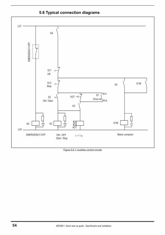
54 ADV200 • Quick start up guide - Specification and installation
5.6 Typical connection diagrams
EM
ER
GE
NC
Y-O
FF
EMERGENCY-OFF
K0
K0
S11
Off
S12Stop
S2
ON / Start
ON / OFF
Start / Stop
K2
K2T
K2T
K2
G1 R11
R14Drive ok
t = 1 s
K2 K1M
K1M
Mains contactor
L01
L00
Figure 5.6.1: Auxiliary control circuits

ADV200 • Quick start up guide - Specification and installation 55
+ 24V
L1
M1
K1M
5
L1 L2 L3 N PE
G1
0 V24
C
D
1 2
3 4
6
SMPS
COM ID
S3
C3
C2
12
7
Fault reset src
Digital input E mon(Enable)
R11
R14
R21
R24
RS 485
S1+
S1-
C1
+ 10 V
- 10 V
0 V 10
1
2
Ana
log
inpu
t1A
nalo
gin
put 2
-
4
3
-+
+
EL2
L3
U
V
W
Multi ref sel 0 src
FR reverse src
FR forward src
Analogoutput 2
Analogoutput 1
5
C1
6
13
IC1COM Dig. Out.3/4
Dig. Out.3
M3~
8
9
10
11
EXP-DE-...(optional)
Dig. Output 2(Relay 2)
Multi ref sel 1 src
IS1
14
PS Dig. Out.3/4
Dig. Out.4
BR1
BR2Braking resistor (optional)
Dig. Output 1(Relay 1)
Drive OK
Drive ready
L1(*)F1
K2
K1M
K0
(**)
OK
Rel
ay(7
0-72
)
(***)
Figure 5.6.2: Typical connection diagram, connection through terminals strip
(*): ADV1007 ... 61320: Integrated choke on DC link; ≥ 716000: external choke mandatory(**): Only for sizes ≥ ADV71600; (***) See chapter 5.1.12, Connection of fans.
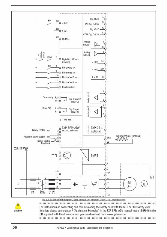
56 ADV200 • Quick start up guide - Specification and installation
+ 24V
L1
M1
K1M
5
L1 L2 L3 NP
E
G1
0 V24
C
D
1 2
3 4
6
SMPS
COM ID
S3
C3
C2
12
7
Fault reset src
Digital input E mon(Enable)
R11
R14
R21
R24
RS 485
S1+
S1-
C1
+ 10 V
- 10 V
0 V 10
1
2
Ana
log
inpu
t 1A
nalo
g in
put 2
-
4
3
-+
+
EL2
L3
U
V
W
Multi ref sel 0 src
FR reverse src
FR forward src
Analogoutput 2
Analogoutput 1
5
C1
6
13
IC1COM Dig. Out.3/4
Dig. Out.3
M3~
8
9
10
11
EXP-DE-...(optional)
Dig. Output 2(Relay 2)
Multi ref sel 1 src
IS1
14
PS Dig. Out.3/4
Dig. Out.4
BR1
BR2Braking resistor (optional)
Dig. Output 1(Relay 1)
Drive OK
Drive ready
L1(*)F1
K2
K1M
K0
(**)
OK
Rel
ay(7
0-72
)
(***)
EXP-SFTy-ADV(on ADV-...-SI models)
1
2
3
4
5
24V+
-Safety Enable
24V+
-Feedback power supply
Safety EnableFeedback
Fig 5.6.3: Simplifi ed diagram, Safe Torque Off function (ADV-...-SI models only)
For instructions on connecting and commissioning the safety card with the SIL2 or SIL3 safety level function, please see chapter 7 “Application Examples” in the EXP-SFTy-ADV manual (code 1S5F94) in the CD supplied with the drive or which you can download from www.gefran.com
Caution

ADV200 • Quick start up guide - Specification and installation 57
+ 24V
C
M1
K1MG1
0 V24
1 2
3 4
SMPS
COM ID
S3
C3
C2
12
7
Fault reset src
Digital input E mon(Enable)
R11
R14
R21
R24
RS 485
S1+
S1-
C1
+ 10 V
- 10 V
0 V 10
1
2
Ana
log
inpu
t 1A
nalo
g in
put 2
-
4
3
-+
+
ED
U
V
W
Multi ref sel 0 src
FR reverse mon
FR start mon
Analogoutput 2
Analogoutput 1
5
C1
6
13
IC1COM Dig. Out.3/4
Dig. Out.3
M3~
8
9
10
11
EXP-DE-...(optional)
Dig. Output 2(Relay 2)
Multi ref sel 1 src
IS1
14
PS Dig. Out.3/4
Dig. Out.4
Dig. Output 1(Relay 1)
Drive OK
Drive ready
F1
K2
K1M
K0
(**)
OK
Rel
ay(7
0-72
)
(*)
(**): For sizes ≥ ADV71600 only; (*) See paragraph “5.1.12 Connection of fans”, page 40.
Fig 5.6.4: Typical connection diagram, command via terminal strip, ADV200-...-DC models
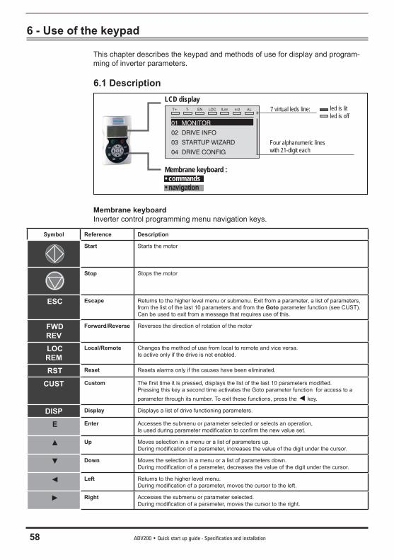
58 ADV200 • Quick start up guide - Specification and installation
6 - Use of the keypad
This chapter describes the keypad and methods of use for display and program-ming of inverter parameters.
6.1 Description
T+ T- EN LOC ILim n:0 AL
01 MONITOR
02 DRIVE INFO
03 STARTUP WIZARD
04 DRIVE CONFIG
7 virtual leds line:
Four alphanumeric lines with 21-digit each
led is litled is off
Membrane keyboard :• commands• navigation
LCD display
Membrane keyboardInverter control programming menu navigation keys.
Symbol Reference Description
Start Starts the motor
Stop Stops the motor
ESC Escape Returns to the higher level menu or submenu. Exit from a parameter, a list of parameters, from the list of the last 10 parameters and from the Goto parameter function (see CUST).Can be used to exit from a message that requires use of this.
FWDREV
Forward/Reverse Reverses the direction of rotation of the motor
LOCREM
Local/Remote Changes the method of use from local to remote and vice versa. Is active only if the drive is not enabled.
RST Reset Resets alarms only if the causes have been eliminated.
CUST Custom The fi rst time it is pressed, displays the list of the last 10 parameters modifi ed. Pressing this key a second time activates the Goto parameter function for access to a parameter through its number. To exit these functions, press the ◄ key.
DISP Display Displays a list of drive functioning parameters.
E Enter Accesses the submenu or parameter selected or selects an operation,Is used during parameter modifi cation to confi rm the new value set.
▲ Up Moves selection in a menu or a list of parameters up.During modifi cation of a parameter, increases the value of the digit under the cursor.
▼ Down Moves the selection in a menu or a list of parameters down.During modifi cation of a parameter, decreases the value of the digit under the cursor.
◄ Left Returns to the higher level menu.During modifi cation of a parameter, moves the cursor to the left.
► Right Accesses the submenu or parameter selected.During modifi cation of a parameter, moves the cursor to the right.
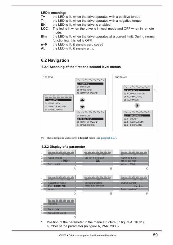
ADV200 • Quick start up guide - Specification and installation 59
LED’s meaning:T+ the LED is lit, when the drive operates with a positive torqueT- the LED is lit, when the drive operates with a negative torqueEN the LED is lit, when the drive is enabledLOC The led is lit when the drive is in local mode and OFF when in remote
mode.Ilim the LED is lit, when the drive operates at a current limit. During normal
functioning, this led is OFF.n=0 the LED is lit; it signals zero speedAL the LED is lit; it signals a trip
6.2 Navigation6.2.1 Scanning of the fi rst and second level menus
T+ T- EN LOC ILim n:0 AL
01 MONITOR
02 DRIVE INFO
03 STARTUP WIZARD
04 DRIVE CONFIG
T+ T- EN LOC ILim n:0 AL
27 SERVICE
01 MONITOR
02 DRIVE INFO
03 STARTUP WIZARDT+ T- EN LOC ILim n:0 AL
01 MONITOR
02 DRIVE INFO
03 STARTUP WIZARD
04 DRIVE CONFIGT+ T- EN LOC ILim n:0 AL
22.1 SPEED RATIO
22.2 DROOP
22.3 INERTIA COMP
22.4 DC BRAKING
T+ T- EN LOC ILim n:0 AL
22 FUNCTIONS
23 COMMUNICATION
24 ALARM CONFIG
25 ALARM LOG
1st level 2nd level
(*)
(*) This example is visible only in Export mode (see paragraph 6.5.2).
6.2.2 Display of a parameterT+ T- EN LOC ILim n:0 ALT+ T- EN LOC ILim n:0 AL T+ T- EN LOC ILim n:0 AL
2
1 3 . 0 5 PA R : 1 3 3 0
Dig out 1 inversion
1 6 . 0 1 PA R : 2 0 0 0
Rated volta eg
+400 V
0 5 . 0 4 PA R : 6 1 0
Ram ref 1 srcp
Mlt ref out mon
1
3
4 Def: +400
A B C
T+ T- EN LOC ILim n:0 ALT+ T- EN LOC ILim n:0 AL T+ T- EN LOC ILim n:0 AL
2
0 4 . 0 1 PA R : 5 5 0
Save arametersp
0 4 . 0 2 PA R : 5 5 2
Regulation mode
V/ f cont ro l
0 1 . 0 1 PA R : 2 5 0
Output current
+0.3 A
1
3
4 Value: 0
D E F
ONValue: 2034
Press E to execute
Param read only
T+ T- EN LOC ILim n:0 AL
2
Autotune1
3
4
Error code: 1
G
Press ESC to exit
1 Position of the parameter in the menu structure (in fi gure A, 16.01); number of the parameter (in fi gure A, PAR: 2000).
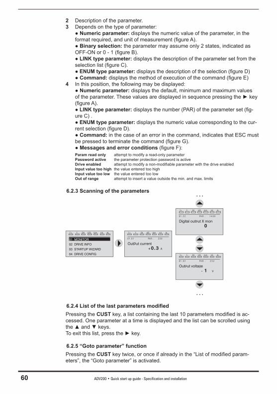
60 ADV200 • Quick start up guide - Specification and installation
2 Description of the parameter.3 Depends on the type of parameter: ● Numeric parameter: displays the numeric value of the parameter, in the
format required, and unit of measurement (fi gure A). ● Binary selection: the parameter may assume only 2 states, indicated as
OFF-ON or 0 - 1 (fi gure B). ● LINK type parameter: displays the description of the parameter set from the
selection list (fi gure C). ● ENUM type parameter: displays the description of the selection (fi gure D) ● Command: displays the method of execution of the command (fi gure E)4 In this position, the following may be displayed: ● Numeric parameter: displays the default, minimum and maximum values
of the parameter. These values are displayed in sequence pressing the ► key (figure A).
● LINK type parameter: displays the number (PAR) of the parameter set (fi g-ure C) .
● ENUM type parameter: displays the numeric value corresponding to the cur-rent selection (fi gure D).
● Command: in the case of an error in the command, indicates that ESC must be pressed to terminate the command (figure G).
● Messages and error conditions (figure F): Param read only attempt to modify a read-only parameter Password active the parameter protection password is active Drive enabled attempt to modify a non-modifi able parameter with the drive enabled Input value too high the value entered too high Input value too low the value entered too low Out of range attempt to insert a value outside the min. and max. limits 6.2.3 Scanning of the parameters
T+ T- EN LOC ILim n:0 AL
01 MONITOR
02 DRIVE INFO
03 STARTUP WIZARD
04 DRIVE CONFIG
T+ T- EN LOC ILim n:0 AL
0 1 . 0 1 PA R : 2 5 0
Output current
+0.3 A
T+ T- EN LOC ILim n:0 AL
0 1 . 0 2 PA R : 2 5 2
Out ut volta ep g
- 1 V
T+ T- EN LOC ILim n:0 AL
0 1 . 2 2 PA R : 1 4 0 0
Digital out ut X monp
0
. . .
. . .
6.2.4 List of the last parameters modifi edPressing the CUST key, a list containing the last 10 parameters modifi ed is ac-cessed. One parameter at a time is displayed and the list can be scrolled using the ▲ and ▼ keys.To exit this list, press the ► key.
6.2.5 “Goto parameter” functionPressing the CUST key twice, or once if already in the “List of modifi ed param-eters”, the “Goto parameter” is activated.
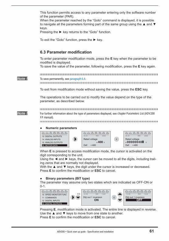
ADV200 • Quick start up guide - Specification and installation 61
This function permits access to any parameter entering only the software number of the parameter (PAR).When the parameter reached by the “Goto” command is displayed, it is possible to navigate all the parameters forming part of the same group using the ▲ and ▼ keys.Pressing the ► key returns to the “Goto” function.
To exit the “Goto” function, press the ► key.
6.3 Parameter modifi cationTo enter parameter modifi cation mode, press the E key when the parameter to be modifi ed is displayed.To save the value of the parameter, following modifi cation, press the E key again.
Note ! To save permanently, see paragraph 6.4.
To exit from modifi cation mode without saving the value, press the ESC key.
The operations to be carried out to modify the value depend on the type of the parameter, as described below.
Note ! For further information about the type of parameters displayed, see chapter Parameters List (ADV200 FP manual).
● Numeric parametersT+ T- EN LOC ILim n:0 AL
13 DIGITAL OUTPUTS
14 ANALOG INPUTS
15 ANALOG OUTPUTS
16 MOTOR DATA
E
T+ T- EN LOC ILim n:0 AL
1 6 . 0 1 PA R : 2 0 0 0
Rated voltage
+400 V
Def: +400
T+ T- EN LOC ILim n:0 AL
1 6 . 0 1 PA R : 2 0 0 0
Rated voltage
+ V
Def: +400
000000400
When E is pressed to access modifi cation mode, the cursor is activated on the digit corresponding to the unit.Using the ◄ and ► keys, the cursor can be moved to all the digits, including trail-ing zeros that are normally not displayed.With the ▲ and ▼ keys, the digit under the cursor is increased or decreased.Press E to confi rm the modifi cation or ESC to cancel.
● Binary parameters (BIT type)The parameter may assume only two states which are indicated as OFF-ON or 0-1.
X 5
T+ T- EN LOC ILim n:0 AL
10 SPEED MONITOR FUNC
11 COMMANDS
12 DIGITAL INPUTS
13 DIGITAL OUTPUTS
E
T+ T- EN LOC ILim n:0 AL
1 3 . 0 5 PA R : 1 3 3 0
Dig out 1 inversion
ON
T+ T- EN LOC ILim n:0 AL
1 3 . 0 5 PA R : 1 3 3 0
Dig out 1 inversion
OFF
Pressing E, modifi cation mode is activated. The entire line is displayed in reverse. Use the ▲ and ▼ keys to move from one state to another.Press E to confi rm the modifi cation or ESC to cancel.
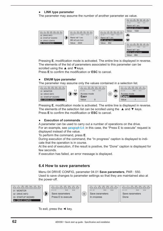
62 ADV200 • Quick start up guide - Specification and installation
● LINK type parameterThe parameter may assume the number of another parameter as value.
T+ T- EN LOC ILim n:0 AL
02 DRIVE INFO
03 STARTUP WIZARD
04 DRIVE CONFIG
05 REFERENCES
E
T+ T- EN LOC ILim n:0 AL
0 5 . 0 4 PA R : 6 1 0
Ram ref 1 srcp
Mlt ref out mon
Value: 2034
T+ T- EN LOC ILim n:0 AL
0 5 . 0 4 PA R : 6 1 0
Ram ref 1 srcp
Value: 852
Mlt ref out mon
T+ T- EN LOC ILim n:0 AL
0 5 . 0 4 PA R : 6 1 0
Ram ref 1 srcp
Value: 1550
Analog input 2 mon
T+ T- EN LOC ILim n:0 AL
0 5 . 0 4 PA R : 6 1 0
Ram ref 1 srcp
Value: 894
Mpot output mon
Pressing E, modifi cation mode is activated. The entire line is displayed in reverse. The elements of the list of parameters associated to this parameter can be scrolled using the ▲ and ▼keys.Press E to confi rm the modifi cation or ESC to cancel.
● ENUM type parameterThe parameter may assume only the values contained in a selection list.
X 2
T+ T- EN LOC ILim n:0 AL
0 4 . 0 3 PA R : 5 5 4
Access mode
EasY
Value 0
T+ T- EN LOC ILim n:0 AL
01 MONITOR
02 DRIVE INFO
03 STARTUP WIZARD
04 DRIVE CONFIG
E
T+ T- EN LOC ILim n:0 AL
0 4 . 0 3 PA R : 5 5 4
Access mode
Ex ertp
Value 1
Pressing E, modifi cation mode is activated. The entire line is displayed in reverse. The elements of the selection list can be scrolled using the ▲ and ▼ keys.Press E to confi rm the modifi cation or ESC to cancel.
● Execution of commandsA parameter can be used to carry out a number of operations on the drive.For an example, see paragraph 6.4: in this case, the “Press E to execute” request is displayed instead of the value.To perform the command, press E.During execution of the command, the “In progress” caption is displayed to indi-cate that the operation is in course. At the end of execution, if the result is positive, the “Done” caption is displayed for few seconds.If execution has failed, an error message is displayed.
6.4 How to save parametersMenu 04 DRIVE CONFIG, parameter 04.01 Save parameters, PAR : 550.Used to save changes to parameter settings so that they are maintained also at the power-off.
T+ T- EN LOC ILim n:0 AL
0 4 . 0 1 PA R : 5 5 0
Save arametersp
Press E to execute
T+ T- EN LOC ILim n:0 AL
01 MONITOR
02 DRIVE INFO
03 STARTUP WIZARD
04 DRIVE CONFIG
E
T+ T- EN LOC ILim n:0 AL
0 4 . 0 1 PA R : 5 5 0
Save arametersp
In ro ressgp
T+ T- EN LOC ILim n:0 AL
0 4 . 0 1 PA R : 5 5 0
Save arametersp
Done
To exit, press the ◄ key.
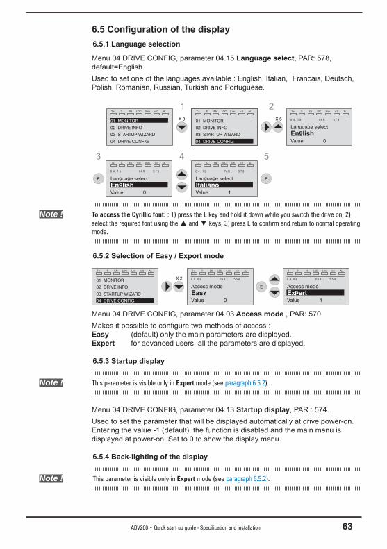
ADV200 • Quick start up guide - Specification and installation 63
6.5 Confi guration of the display6.5.1 Language selection
Menu 04 DRIVE CONFIG, parameter 04.15 Language select, PAR: 578, default=English.Used to set one of the languages available : English, Italian, Francais, Deutsch, Polish, Romanian, Russian, Turkish and Portuguese.
X 5
T+ T- EN LOC ILim n:0 AL
0 4 . 1 5 PA R : 5 7 8
Lan ua e selectg g
En lishg
Value 0
T+ T- EN LOC ILim n:0 AL
0 4 . 1 5 PA R : 5 7 8
Lan ua e selectg g
ItalianoValue 1
1 2
4T+ T- EN LOC ILim n:0 AL
0 4 . 1 5 PA R : 5 7 8
Lan ua e selectg g
En lishg
Value 0
E
3
E
5
T+ T- EN LOC ILim n:0 AL
01 MONITOR
02 DRIVE INFO
03 STARTUP WIZARD
04 DRIVE CONFIG
X 3
T+ T- EN LOC ILim n:0 AL
01 MONITOR
02 DRIVE INFO
03 STARTUP WIZARD
04 DRIVE CONFIG
Note ! To access the Cyrillic font: : 1) press the E key and hold it down while you switch the drive on, 2) select the required font using the ▲ and ▼ keys, 3) press E to confirm and return to normal operating mode.
6.5.2 Selection of Easy / Export mode
X 2
T+ T- EN LOC ILim n:0 AL
0 4 . 0 3 PA R : 5 5 4
Access mode
EasY
Value 0
T+ T- EN LOC ILim n:0 AL
01 MONITOR
02 DRIVE INFO
03 STARTUP WIZARD
04 DRIVE CONFIG
E
T+ T- EN LOC ILim n:0 AL
0 4 . 0 3 PA R : 5 5 4
Access mode
Ex ertp
Value 1
Menu 04 DRIVE CONFIG, parameter 04.03 Access mode , PAR: 570.Makes it possible to confi gure two methods of access :Easy (default) only the main parameters are displayed.Expert for advanced users, all the parameters are displayed.
6.5.3 Startup display
Note ! This parameter is visible only in Expert mode (see paragraph 6.5.2).
Menu 04 DRIVE CONFIG, parameter 04.13 Startup display, PAR : 574.Used to set the parameter that will be displayed automatically at drive power-on.Entering the value -1 (default), the function is disabled and the main menu is displayed at power-on. Set to 0 to show the display menu.
6.5.4 Back-lighting of the display
Note ! This parameter is visible only in Expert mode (see paragraph 6.5.2).
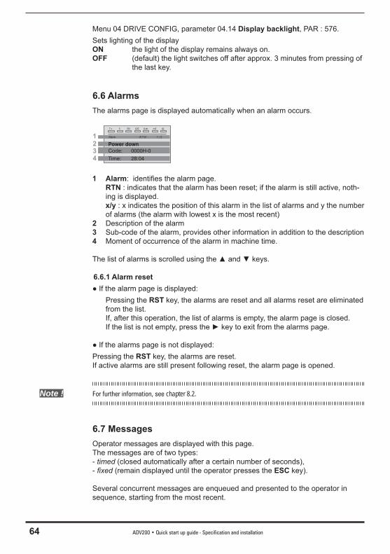
64 ADV200 • Quick start up guide - Specification and installation
Menu 04 DRIVE CONFIG, parameter 04.14 Display backlight, PAR : 576.Sets lighting of the displayON the light of the display remains always on.OFF (default) the light switches off after approx. 3 minutes from pressing of
the last key.
6.6 AlarmsThe alarms page is displayed automatically when an alarm occurs.
T+ T- EN LOC ILim n:0 AL
2
Alarm -R T N : 1 / 2
Power down
1
3
4 Time: 28:04
Code: 0000H-0
1 Alarm: identifi es the alarm page. RTN : indicates that the alarm has been reset; if the alarm is still active, noth-
ing is displayed. x/y : x indicates the position of this alarm in the list of alarms and y the number
of alarms (the alarm with lowest x is the most recent)2 Description of the alarm3 Sub-code of the alarm, provides other information in addition to the description4 Moment of occurrence of the alarm in machine time.
The list of alarms is scrolled using the ▲ and ▼ keys.
6.6.1 Alarm reset● If the alarm page is displayed: Pressing the RST key, the alarms are reset and all alarms reset are eliminated
from the list. If, after this operation, the list of alarms is empty, the alarm page is closed. If the list is not empty, press the ► key to exit from the alarms page.
● If the alarms page is not displayed:Pressing the RST key, the alarms are reset.If active alarms are still present following reset, the alarm page is opened.
Note ! For further information, see chapter 8.2.
6.7 MessagesOperator messages are displayed with this page.The messages are of two types: - timed (closed automatically after a certain number of seconds),- fi xed (remain displayed until the operator presses the ESC key).
Several concurrent messages are enqueued and presented to the operator in sequence, starting from the most recent.
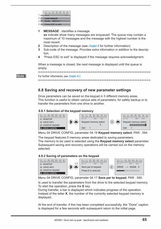
ADV200 • Quick start up guide - Specification and installation 65
T+ T- EN LOC ILim n:0 AL
2
Message 0 1
Load default
1
3
4 Press ESC to exit
Code: 0001H-1
1 MESSAGE : identifi es a message. xx indicate show many messages are enqueued. The queue may contain a
maximum of 10 messages and the message with the highest number is the most recent.
2 Description of the message (see chapter 8 for further information)3 Sub-code of the message. Provides extra information in addition to the descrip-
tion.4 “Press ESC to exit” is displayed if the message requires acknowledgment.
When a message is closed, the next message is displayed until the queue is empty.
Note ! For further information, see chapter 8.2.
6.8 Saving and recovery of new parameter settingsDrive parameters can be saved on the keypad in 5 different memory areas.This function is useful to obtain various sets of parameters, for safety backup or to transfer the parameters from one drive to another.
6.8.1 Selection of the keypad memoryT+ T- EN LOC ILim n:0 AL
0 4 . 1 9 PA R : 5 9 4
Keypad memory select
Def: 1
T+ T- EN LOC ILim n:0 AL
01 MONITOR
02 DRIVE INFO
03 STARTUP WIZARD
04 DRIVE CONFIG
E
T+ T- EN LOC ILim n:0 AL
0 4 . 1 9 PA R : 5 9 4
Keypad memory select
Def: 1
1 000000002
Menu 04 DRIVE CONFIG, parameter 04.19 Keypad memory select, PAR : 594.The keypad features 5 memory areas dedicated to saving parameters.The memory to be used is selected using the Keypad memory select parameter.Subsequent saving and recovery operations will be carried out on the memory selected.
6.8.2 Saving of parameters on the keypadT+ T- EN LOC ILim n:0 AL
0 4 . 1 7 PA R : 5 9 0
Save par to keypad
Press E to execute
E
T+ T- EN LOC ILim n:0 AL
0 4 . 1 7 PA R : 5 9 0
DRIVE --> K2006 X
T+ T- EN LOC ILim n:0 AL
01 MONITOR
02 DRIVE INFO
03 STARTUP WIZARD
04 DRIVE CONFIG
X 3
Menu 04 DRIVE CONFIG, parameter 04.17 Save par to keypad, PAR : 590.Is used to transfer the parameters from the drive to the selected keypad memory.To start the operation, press the E key. During transfer, a bar is displayed which indicates progress of the operation.Instead of the letter X, the number of the currently selected keypad memory is displayed.
At the end of transfer, if this has been completed successfully, the “Done” caption is displayed for a few seconds with subsequent return to the initial page.
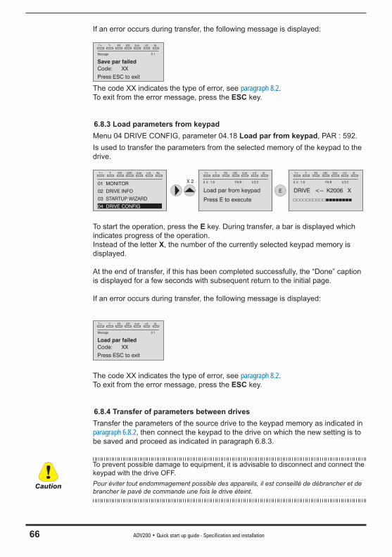
66 ADV200 • Quick start up guide - Specification and installation
If an error occurs during transfer, the following message is displayed:
T+ T- EN LOC ILim n:0 AL
Message 0 1
Save par failed
Press ESC to exit
Code: XX
The code XX indicates the type of error, see paragraph 8.2.To exit from the error message, press the ESC key.
6.8.3 Load parameters from keypadMenu 04 DRIVE CONFIG, parameter 04.18 Load par from keypad, PAR : 592.Is used to transfer the parameters from the selected memory of the keypad to the drive.
T+ T- EN LOC ILim n:0 AL
0 4 . 1 8 PA R : 5 9 2
Load par from keypad
Press E to execute
E
T+ T- EN LOC ILim n:0 AL
0 4 . 1 8 PA R : 5 9 2
DRIVE <-- K2006 X
T+ T- EN LOC ILim n:0 AL
01 MONITOR
02 DRIVE INFO
03 STARTUP WIZARD
04 DRIVE CONFIG
X 2
To start the operation, press the E key. During transfer, a bar is displayed which indicates progress of the operation.Instead of the letter X, the number of the currently selected keypad memory is displayed.
At the end of transfer, if this has been completed successfully, the “Done” caption is displayed for a few seconds with subsequent return to the initial page.
If an error occurs during transfer, the following message is displayed:
T+ T- EN LOC ILim n:0 AL
Message 0 1
Load par failed
Press ESC to exit
Code: XX
The code XX indicates the type of error, see paragraph 8.2.To exit from the error message, press the ESC key.
6.8.4 Transfer of parameters between drivesTransfer the parameters of the source drive to the keypad memory as indicated in paragraph 6.8.2, then connect the keypad to the drive on which the new setting is to be saved and proceed as indicated in paragraph 6.8.3.
To prevent possible damage to equipment, it is advisable to disconnect and connect the keypad with the drive OFF.Pour éviter tout endommagement possible des appareils, il est conseillé de débrancher et de brancher le pavé de commande une fois le drive éteint.
Caution
ADV200 • Quick start up guide - Specification and installation 67
7 - Commissioning via keypad (STARTUP WIZARD)
Adjustable frequency drives are electrical apparatus for use in industrial installations. Parts of the Drives are energized during operation. The electrical installation and the opening of the device should therefore only be carried out by qualifi ed personnel. Im-proper installation of motors or Drives may therefore cause the failure of the device as well as serious injury to persons or material damage. Drive is not equipped with motor overspeed protection logic other than that controlled by software. Follow the instructions given in this manual and observe the local and national safety regulations applicable.Les drives à fréquence variable sont des dispositifs électriques utilisés dans des installations industriels. Une partie des drives sont sous tension pendant l’operation. L’installation élec-trique et l’ouverture des drives devrait être executé uniquement par du personel qualifi é. De mauvaises installations de moteurs ou de drives peuvent provoquer des dommages materiels ou blesser des personnes. On doit suivir les instructions donneés dans ce manuel et observer les régles nationales de sécurité.
Always connect the Drive to the protective ground (PE) via the marked connection .ADV Drives and AC Input fi lters have ground discharge currents greater than 3.5 mA. EN 50178 specifi es that with discharge currents greater than 3.5 mA the protective conductor ground connection ( ) must be fi xed type and doubled for redundancy.Il faut toujours connecter le variateur à la terre (PE). Le courant de dispersion vers la terre est supérieur à 3,5 mA sur les variateurs et sur les fi ltres à courant alterné. Les normes EN 50178 spécifi ent qu’en cas de courant de dispersion vers la terre, supérieur à 3,5 ma, la mise à la terre ( ) doit avoir une double connexion pour la redondance.
Only permanently-wired input power connections are allowed. This equipment must be grounded (IEC 536 Class 1, NEC and other applicable standards).If a Residual Current-operated protective Device (RCD) is to be used, it must be an RCD type B. Machines with a three phase power supply, fi tted with EMC fi lters, must not be connected to a supply via an ELCB (Earth Leakage Circuit-Breaker - see DIN VDE 0160, section 5.5.2 and EN50178 section 5.2.11.1). The following terminals can carry dangerous voltages even if the inverter is inoperative:- the power supply terminals L1, L2, L3, C, D.- the motor terminals U, V, W.This equipment must not be used as an ‘emergency stop mechanism’ (see EN 60204, 9.2.5.4).Seuls des branchements électriques permanents par câble en entrée sont admis. Mettre l’appareil à la masse (IEC 536 Classe 1, NEC et autres normes applicables).S’il s’avère nécessaire d’utiliser un dispositif protecteur de courant résiduel (RCD), il convient de choisir un RCD de type B. Les machines à alimentation triphasée et dotées de fi ltres EMC ne doivent pas être raccordées au bloc d’alimentation par le biais d’un disjoncteur ELCB (Earth Leakage Circuit-Breaker – cf. DIN VDE 0160, paragraphe 5.5.2 et EN50178 para-graphe 5.2.11.1).Les bornes suivantes peuvent recevoir des tensions dangereuses, même si l’onduleur est désactivé :- bornes d’alimentation L1, L2, L3, C, D.- bornes du moteur U, V, W.Ne pas utiliser cet appareil en tant que « dispositif d’arrêt d’urgence » (cf. EN 60204, 9.2.5.4).
Do not touch or damage any components when handling the device. The changing of the isolation gaps or the removing of the isolation and covers is not permissible.Manipuler l’appareil de façon à ne pas toucher ou endommager des parties. Il n’est pas permis de changer les distances d’isolement ou bien d’enlever des matériaux isolants ou des capots.
Warning!
68 ADV200 • Quick start up guide - Specification and installation
According to the EEC standards the ADV and accessories must be used only after checking that the machine has been produced using those safety devices required by the 89/392/EEC set of rules, as far as the machine industry is concerned. These standards do not apply in the Americas, but may need to be considered in equipment being shipped to Europe.Selon les normes EEC, les drives ADV et leurs accessoires doivent être employés seule-ment après avoir verifi é que la machine ait été produit avec les même dispositifs de sécurité demandés par la réglementation 89/392/EEC concernant le secteur de l’industrie.
Motor parameters must be accurately confi gured for the motor overload protection to operate correctly.Confi gurer soigneusement les paramètres du moteur afi n que la protection contre les sur-charges équipée sur le moteur fonctionne convenablement.
ADV200 operate at high voltages.L’ADV200 fonctionne à des tensions élevées.
When operating electrical devices, it is impossible to avoid applying hazardous voltages to certain parts of the equipment.L’actionnement de dispositifs électriques fait qu’il est impossible d’éviter l’application de ten-sions dangereuses sur certaines parties de l’appareil.
Wherever faults occurring in the control equipment can lead to substantial material dam-age or even grievous bodily injury (i.e. potentially dangerous faults), additional external precautions must be taken or facilities provided to ensure or enforce safe operation, even when a fault occurs (e.g. independent limit switches, mechanical interlocks, etc.).Adopter des mesures de précaution supplémentaires à l’extérieur du drive (par exemple, des interrupteurs de fi n de course, des interrupteurs mécaniques, etc.) ou fournir des fonctions aptes à garantir ou à mettre en place un fonctionnement sécurisé en cas de survenue d’une panne de l’appareil de commande susceptible d’occasionner des dégâts matériels d’enver-gure, voire même des lésions corporelles graves (par exemple, des pannes potentiellement dangereuses).
Certain parameter settings may cause the inverter to restart automatically after an input power failure.Certaines confi gurations de paramètres peuvent provoquer le redémarrage automatique de l’onduleur après une coupure de l’alimentation.
This equipment is suitable for use in a circuit capable of delivering not more than 10,000 symmetrical amperes (rms), for a maximum voltage of 480 V .Cet appareil est conçu pour une utilisation sur un circuit d’alimentation en mesure de délivrer 10.000 ampères symétriques (rms) maximum pour une tension maximale de 480V.
This equipment must not be used as an ‘emergency stop mechanism’ (see EN 60204, 9.2.5.4).Ne pas utiliser cet appareil en tant que « dispositif d’arrêt d’urgence » (cf. EN 60204, 9.2.5.4).
Never open the device or covers while the AC Input power supplyis switched on. Minimum time to wait before working on the terminals or inside the device is listed in section 9.8 .Ne jamais ouvrir l’appareil lorsqu’il est suns tension. Le temps minimum d’attente avant de pou-voir travailler sur les bornes ou bien àl’intérieur de l’appareil est indiqué dans la section 9.8 .
ADV200 • Quick start up guide - Specification and installation 69
Fire and Explosion Hazard:Fires or explosions might result from mounting Drives in hazardous areas such as locations where fl ammable or combustible vapors or dusts are present. Drives should be installed away from hazardous areas, even if used with motors suitable for use in these locations.Risque d’incendies et d’explosions. L’utilisation des drives dans des zônes à risques (présence de vapeurs ou de poussières infl ammables), peut provoquer des incendies ou des explosions. Les drives doivent être installés loin des zônes dangeureuses, et équipés de moteurs appropriés.
Protect the device from impermissible environmental conditions (temperature, humidity, shock etc.).Protéger l’appareil contre des effets extérieurs non permis (température, humidité, chocs etc.).
To the output of the drive (terminals U2, V2, W2) :- no voltage should be connected to the output of the drive- the parallel connection of several drives are not permissible.- the direct connection of the inputs and outputs (bypass) are not permissible.- capacitative load (e.g. Var compensation capacitors) should not be connected.À la sortie du convertisseur (bornes U2, V2 et W2) :- aucune tension ne doit être appliquée- aucune charge capacitive ne doit être connectée- il n’est paspermis de raccorder la sortie de plusieurs convertisseurs en parallèle- l n’est paspermis d’effectuer une connexion directede l’entrée avec la sortie du convertisseur (Bypass).
The electrical commissioning should only be carried out by qualifi ed personnel, who are also responsible for the provision of a suitable ground connection and a protected power supply feeder in accordance with the local and national regulations. The motor must be protected against overloads.La mise en service électrique doit être effectuée par un personnel qualifi é. Ce dernier est responsable del’existence d’une connexion de terre adéquate et d’une protection des câbles d’alimentation selon les prescriptions locales et nationales. Le moteur doit être protégé contre la surcharge.
Do not connect power supply voltage that exceeds the standard specifi cation voltage fl uctuation permissible. If excessive voltage is applied to the Drive, damage to the internal components will result.Ne pas raccorder de tension d’alimentation dépassant la fl uctuation de tension permise par les normes. Dans le cas d’ une alimentation en tension excessive, des composants internes peuvent être endommagés.
Do not operate the Drive without the ground wire connected. The motor chassis should be grounded to earth through a ground lead separate from all other equipment ground leads to prevent noise coupling.Ne pas faire fonctionner le drive sans prise de terre. Le chassis du moteur doit être mis à la terre à l’aide d’un connecteur de terre separé des autres pour éviter le couplage des perturbations.
Caution

70 ADV200 • Quick start up guide - Specification and installation
No dielectric tests should be carried out on parts of the drive. A suitable measuring instrument (internal resistance of at least 10 kΩ/V) should be used for measuring the signal voltages.Il ne faut pas éxécuter de tests de rigidité diélectrique sur des parties du convertisseurs. Pour mesurer lestensions, des signaux, il faut utiliser des instruments de mesure appropriés (résis-tance interne minimale 10kΩ/V).
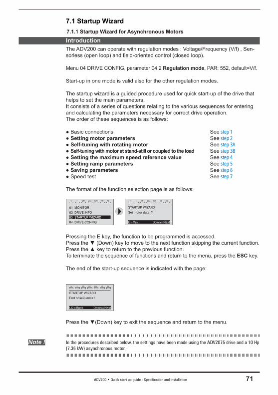
ADV200 • Quick start up guide - Specification and installation 71
7.1 Startup Wizard7.1.1 Startup Wizard for Asynchronous MotorsIntroductionThe ADV200 can operate with regulation modes : Voltage/Frequency (V/f) , Sen-sorless (open loop) and fi eld-oriented control (closed loop).
Menu 04 DRIVE CONFIG, parameter 04.2 Regulation mode, PAR: 552, default=V/f.
Start-up in one mode is valid also for the other regulation modes.
The startup wizard is a guided procedure used for quick start-up of the drive that helps to set the main parameters.It consists of a series of questions relating to the various sequences for entering and calculating the parameters necessary for correct drive operation. The order of these sequences is as follows:
● Basic connections See step 1● Setting motor parameters See step 2● Self-tuning with rotating motor See step 3A● Self-tuning with motor at stand-still or coupled to the load See step 3B● Setting the maximum speed reference value See step 4● Setting ramp parameters See step 5● Saving parameters See step 6● Speed test See step 7
The format of the function selection page is as follows:
T+ T- EN LOC ILim n:0 AL
01 MONITOR
02 DRIVE INFO
03 STARTUP WIZARD
04 DRIVE CONFIG
T+ T- EN LOC ILim n:0 AL
STARTUP WIZARD
Set motor data ?
E=Yes Down=Next
Pressing the E key, the function to be programmed is accessed.Press the ▼ (Down) key to move to the next function skipping the current function.Press the ▲ key to return to the previous function.To terminate the sequence of functions and return to the menu, press the ESC key.
The end of the start-up sequence is indicated with the page:
T+ T- EN LOC ILim n:0 AL
STARTUP WIZARD
End of sequence !
Up=Back Down=Next
Press the ▼(Down) key to exit the sequence and return to the menu.
Note ! In the procedures described below, the settings have been made using the ADV2075 drive and a 10 Hp (7.36 kW) asynchronous motor.
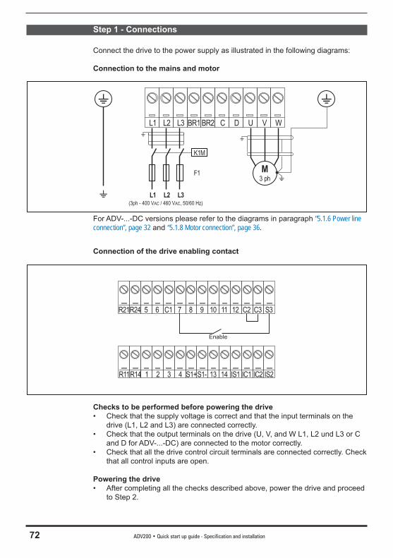
72 ADV200 • Quick start up guide - Specification and installation
Step 1 - Connections
Connect the drive to the power supply as illustrated in the following diagrams:
Connection to the mains and motor
L1 L2 L3 BR1 BR2 C D U V W
K1M
L1 L2 L3
F1
(3ph - 400 V / 460 V 50/60 Hz)AC AC,
M3 ph
For ADV-...-DC versions please refer to the diagrams in paragraph “5.1.6 Power line connection”, page 32 and “5.1.8 Motor connection”, page 36.
Connection of the drive enabling contact
R21R24 5 6 C1 7 8 9 10 11 12 C2 C3 S3
R11R14 1 2 3 4 S1+S1- 13 14 IS1 IC1 IC2 IS2
Enable
Checks to be performed before powering the drive• Check that the supply voltage is correct and that the input terminals on the
drive (L1, L2 and L3) are connected correctly.• Check that the output terminals on the drive (U, V, and W L1, L2 und L3 or C
and D for ADV-...-DC) are connected to the motor correctly.• Check that all the drive control circuit terminals are connected correctly. Check
that all control inputs are open. Powering the drive• After completing all the checks described above, power the drive and proceed
to Step 2.
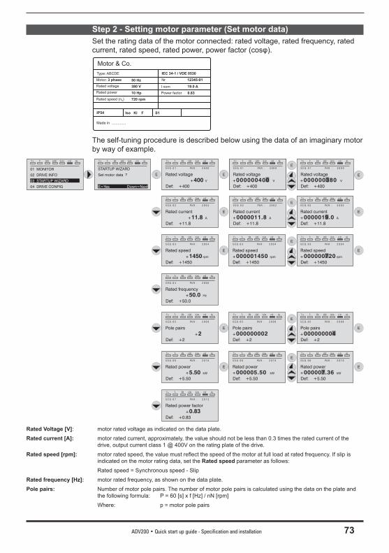
ADV200 • Quick start up guide - Specification and installation 73
Step 2 - Setting motor parameter (Set motor data)Set the rating data of the motor connected: rated voltage, rated frequency, rated current, rated speed, rated power, power factor (cosφ).
10 Hp
Motor: 3 phase
720 rpm
Motor & Co.
Type: ABCDE
380 V
IP54
Made in ..............
19.0 A
IEC 34-1 / VDE 0530
Iso Kl F
Nr. 12345-91
S1
50 Hz
Power factor 0.83
I nomRated voltage
Rated power
Rated speed (n )N
The self-tuning procedure is described below using the data of an imaginary motor by way of example.
T+ T- EN LOC ILim n:0 AL
01 MONITOR
02 DRIVE INFO
03 STARTUP WIZARD
04 DRIVE CONFIG
T+ T- EN LOC ILim n:0 AL
STARTUP WIZARD
Set motor data ?
E=Yes Down=Next
E
T+ T- EN LOC ILim n:0 AL
S E Q . 0 1 PA R : 2 0 0 0
Rated voltage
+400 V
Def: +400
T+ T- EN LOC ILim n:0 AL
1 3 . 0 1 PA R : 1 0 0
Rated voltage
+ V
Def: +400
000000400E
T+ T- EN LOC ILim n:0 AL
S E Q . 0 1 PA R : 2 0 0 0
Rated voltage
+ V
Def: +400
000000400
T+ T- EN LOC ILim n:0 AL
S E Q . 0 1 PA R : 2 0 0 0
Rated voltage
+ V
Def: +400
000000380
E
E
T+ T- EN LOC ILim n:0 AL
S E Q . 0 2 PA R : 2 0 0 2
Rated current
+11.8 A
Def: +11.8
E E
T+ T- EN LOC ILim n:0 AL
S E Q . 0 2 PA R : 2 0 0 2
Rated current
+0000011.8 A
Def: +11.8
E
T+ T- EN LOC ILim n:0 AL
S E Q . 0 2 PA R : 2 0 0 2
Rated current
+ A
Def: +11.8
0000019.0
T+ T- EN LOC ILim n:0 AL
S E Q . 0 3 PA R : 2 0 0 4
Rated speed
+1450 rpm
Def: +1450
E E
E
T+ T- EN LOC ILim n:0 AL
S E Q . 0 3 PA R : 2 0 0 4
Rated speed
+ rpm
Def: +1450
000000720
T+ T- EN LOC ILim n:0 AL
S E Q . 0 3 PA R : 2 0 0 4
Rated speed
+000001450 rpm
Def: +1450
T+ T- EN LOC ILim n:0 AL
S E Q . 0 4 PA R : 2 0 0 6
Rated frequency
+50.0 Hz
Def: +50.0
T+ T- EN LOC ILim n:0 AL
S E Q . 0 5 PA R : 2 0 0 8
Pole pairs
+2Def: +2
E E
E
T+ T- EN LOC ILim n:0 AL
S E Q . 0 5 PA R : 2 0 0 8
Pole pairs
+
Def: +2
000000004
T+ T- EN LOC ILim n:0 AL
S E Q . 0 5 PA R : 2 0 0 8
Pole pairs
+000000002Def: +2
T+ T- EN LOC ILim n:0 AL
S E Q . 0 6 PA R : 2 0 1 0
Rated power
+5.50 kW
Def: +5.50
E E
E
T+ T- EN LOC ILim n:0 AL
S E Q . 0 6 PA R : 2 0 1 0
Rated power
+ kW
Def: +5.50
000007.36
T+ T- EN LOC ILim n:0 AL
S E Q . 0 6 PA R : 2 0 1 0
Rated power
+000005.50 kW
Def: +5.50
T+ T- EN LOC ILim n:0 AL
S E Q . 0 7 PA R : 2 0 1 2
Rated power factor
+0.83Def: +0.83
Rated Voltage [V]: motor rated voltage as indicated on the data plate.
Rated current [A]: motor rated current, approximately, the value should not be less than 0.3 times the rated current of the drive, output current class 1 @ 400V on the rating plate of the drive.
Rated speed [rpm]: motor rated speed, the value must refl ect the speed of the motor at full load at rated frequency. If slip is indicated on the motor rating data, set the Rated speed parameter as follows:
Rated speed = Synchronous speed - Slip
Rated frequency [Hz]: motor rated frequency, as shown on the data plate.
Pole pairs: Number of motor pole pairs. The number of motor pole pairs is calculated using the data on the plate and the following formula: P = 60 [s] x f [Hz] / nN [rpm]
Where: p = motor pole pairs
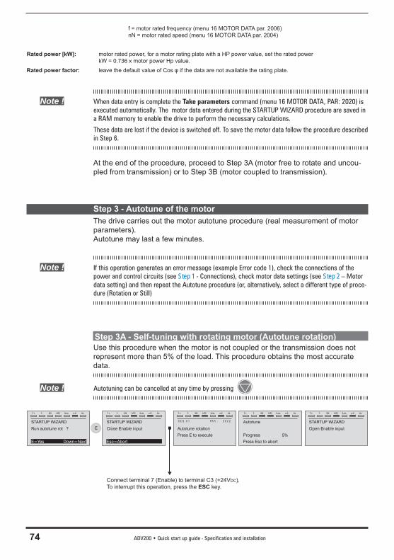
74 ADV200 • Quick start up guide - Specification and installation
f = motor rated frequency (menu 16 MOTOR DATA par. 2006) nN = motor rated speed (menu 16 MOTOR DATA par. 2004)
Rated power [kW]: motor rated power, for a motor rating plate with a HP power value, set the rated power kW = 0.736 x motor power Hp value.
Rated power factor: leave the default value of Cos φ if the data are not available the rating plate.
Note ! When data entry is complete the Take parameters command (menu 16 MOTOR DATA, PAR: 2020) is executed automatically. The motor data entered during the STARTUP WIZARD procedure are saved in a RAM memory to enable the drive to perform the necessary calculations.
These data are lost if the device is switched off. To save the motor data follow the procedure described in Step 6.
At the end of the procedure, proceed to Step 3A (motor free to rotate and uncou-pled from transmission) or to Step 3B (motor coupled to transmission).
Step 3 - Autotune of the motorThe drive carries out the motor autotune procedure (real measurement of motor parameters).Autotune may last a few minutes.
Note ! If this operation generates an error message (example Error code 1), check the connections of the power and control circuits (see Step 1 - Connections), check motor data settings (see Step 2 – Motor data setting) and then repeat the Autotune procedure (or, alternatively, select a different type of proce-dure (Rotation or Still)
Step 3A - Self-tuning with rotating motor (Autotune rotation)Use this procedure when the motor is not coupled or the transmission does not represent more than 5% of the load. This procedure obtains the most accurate data.
Note ! Autotuning can be cancelled at any time by pressing
T+ T- EN LOC ILim n:0 AL
STARTUP WIZARD
Run autotune rot ?
E=Yes Down=Next
E
T+ T- EN LOC ILim n:0 AL
STARTUP WIZARD
Close Enable input
Esc=Abort
T+ T- EN LOC ILim n:0 AL
Autotune rotation
S E Q . 0 1 PA R : 2 0 2 2
Press E to execute
T+ T- EN LOC ILim n:0 AL
Autotune
Press Esc to abort
Progress 5%
T+ T- EN LOC ILim n:0 AL
STARTUP WIZARD
Open Enable input
Connect terminal 7 (Enable) to terminal C3 (+24VDC). To interrupt this operation, press the ESC key.
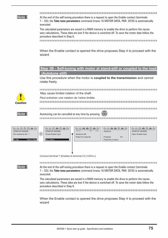
ADV200 • Quick start up guide - Specification and installation 75
Note ! At the end of the self-tuning procedure there is a request to open the Enable contact (terminals 7 – S3); the Take tune parameters command (menu 16 MOTOR DATA, PAR: 2078) is automatically executed.
The calculated parameters are saved in a RAM memory to enable the drive to perform the neces-sary calculations. These data are lost if the device is switched off. To save the motor data follow the procedure described in Step 6.
When the Enable contact is opened the drive proposes Step 4 to proceed with the wizard
Step 3B - Self-tuning with motor at stand-still or coupled to the load (Autotune still)Use this procedure when the motor is coupled to the transmission and cannot rotate freely.
May cause limited rotation of the shaft.Peut entraîner une rotation de l’arbre limitée.
Note ! Autotuning can be cancelled at any time by pressing
T+ T- EN LOC ILim n:0 AL
STARTUP WIZARD
Run autotune still ?
E=Yes Down=Next
E
T+ T- EN LOC ILim n:0 AL
STARTUP WIZARD
Close Enable input
Esc=Abort
T+ T- EN LOC ILim n:0 AL
Autotune still
S E Q . 0 1 PA R : 2 0 2 4
Press E to execute
T+ T- EN LOC ILim n:0 AL
Autotune
Press Esc to abort
Progress 5%
T+ T- EN LOC ILim n:0 AL
STARTUP WIZARD
Open Enable input
Connect terminal 7 (Enable) to terminal C3 (+24VDC)
Note ! At the end of the self-tuning procedure there is a request to open the Enable contact (terminals 7 – S3); the Take tune parameters command (menu 16 MOTOR DATA, PAR: 2078) is automatically executed.
The calculated parameters are saved in a RAM memory to enable the drive to perform the neces-sary calculations. These data are lost if the device is switched off. To save the motor data follow the procedure described in Step 6.
When the Enable contact is opened the drive proposes Step 4 to proceed with the wizard
Caution
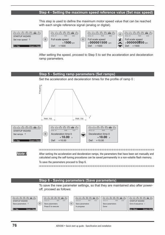
76 ADV200 • Quick start up guide - Specification and installation
Step 4 - Setting the maximum speed reference value (Set max speed)
This step is used to defi ne the maximum motor speed value that can be reached with each single reference signal (analog or digital).
T+ T- EN LOC ILim n:0 AL
STARTUP WIZARD
Set max speed ?
E=Yes Down=Next
E
T+ T- EN LOC ILim n:0 AL
S E Q . 0 1 PA R : 6 8 0
Full scale speed
+1500 rpm
Def: +1500
E
E
T+ T- EN LOC ILim n:0 AL
S E Q . 0 1 PA R : 6 8 0
Full scale speed
+ rpm
Def: +1500
000000750
T+ T- EN LOC ILim n:0 AL
S E Q . 0 1 PA R : 6 8 0
Full scale speed
+000001500 rpm
Def: +1500
After setting the speed, proceed to Step 5 to set the acceleration and deceleration ramp parameters.
Step 5 - Setting ramp parameters (Set ramps)Set the acceleration and deceleration times for the profi le of ramp 0 :
PAR: 700 PAR: 700
Fre
quency
T
T+ T- EN LOC ILim n:0 AL
STARTUP WIZARD
Set ramps ?
E=Yes Down=Next
E
T+ T- EN LOC ILim n:0 AL
S E Q . 0 1 PA R : 7 0 0
Acceleration time 0
+10.00 s
Def: +10.00
T+ T- EN LOC ILim n:0 AL
S E Q . 0 2 PA R : 7 0 2
Deceleration time 0
+10.00 s
Def: +10.00
Note ! After setting the acceleration and deceleration ramps, the parameters that have been set manually and calculated using the self-tuning procedures can be saved permanently in a non-volatile flash memory.
To save the parameters proceed to Step 6.
Step 6 - Saving parameters (Save parameters)To save the new parameter settings, so that they are maintained also after power-off, proceed as follows:
T+ T- EN LOC ILim n:0 AL
STARTUP WIZARD
Save parameters ?
E=Yes Down=Next
E
T+ T- EN LOC ILim n:0 AL
Save parameters
S E Q . 0 1 PA R : 5 5 0
Press E to execute
E
T+ T- EN LOC ILim n:0 AL
Save parameters
S E Q . 0 1 PA R : 5 5 0
In progress
T+ T- EN LOC ILim n:0 AL
Save parameters
S E Q . 0 1 PA R : 5 5 0
Done
T+ T- EN LOC ILim n:0 AL
STARTUP WIZARD
End of sequence !
Up=Back Down=Exit
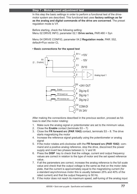
ADV200 • Quick start up guide - Specification and installation 77
Step 7 - Motor speed adjustment test In this step the basic settings in order to perform a functional test of the drive-motor system are described. This functional test uses factory settings as far as the analog and digital commands of the drive are concerned. The preset regulation mode is V/f.
Before starting, check the following setting:Menu 02 DRIVE INFO, parameter 02.1 Drive series, PAR:480 = Syn
Menu 04 DRIVE CONFIG, parameter 04.2 Regulation mode, PAR: 552, default=Flux vector CL
• Basic connections for the speed test
S1+
1
S1-
C1
C2
C3
+10V
0V10
Analog input 1
COM-DI
0V 24V
- 10V
S3
9
7
8
FR reverse src
Enable
FR forward src
+24V OUT
Dig.inp 1
Dig.inp 2
Dig.inp E
2+
-
R1(2 ... 5 kohm)
After making the connections described in the previous section, proceed as fol-lows to start the motor rotating:1. Make sure the analog signal or potentiometer are set to the minimum value.2. Close the Enable contact (terminals S3 – 7)3. Close the FR forward src (PAR 1042) contact, terminals S3 – 8. The drive
starts magnetizing the motor4. Increase the reference signal gradually using the potentiometer or analog
signal5. If the motor rotates anti-clockwise with the FR forward src (PAR 1042) com-
mand and a positive analog reference, stop the drive, disconnect the power supply and invert two phases between U, V and W.
6. Press the DISP key to check that the voltage, current and output frequency values are correct in relation to the type of motor and the set speed reference value.
7. If all the parameters are correct, increase the analog reference to the full scale value and check that the output voltage is the same as that on the motor data plate, that the current is approximately equal to the magnetizing current (for a standard asynchronous motor this is usually between 25% and 40% of the rated current) and that the output frequency is 50 Hz.
8. If the motor does not reach its maximum speed, self-tuning of the analog input
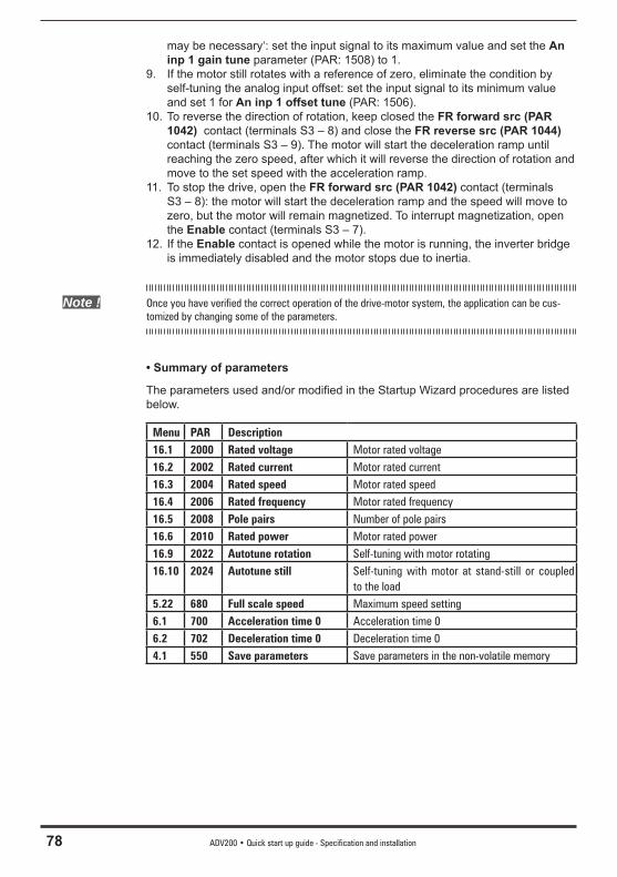
78 ADV200 • Quick start up guide - Specification and installation
may be necessary‘: set the input signal to its maximum value and set the An inp 1 gain tune parameter (PAR: 1508) to 1.
9. If the motor still rotates with a reference of zero, eliminate the condition by self-tuning the analog input offset: set the input signal to its minimum value and set 1 for An inp 1 offset tune (PAR: 1506).
10. To reverse the direction of rotation, keep closed the FR forward src (PAR 1042) contact (terminals S3 – 8) and close the FR reverse src (PAR 1044) contact (terminals S3 – 9). The motor will start the deceleration ramp until reaching the zero speed, after which it will reverse the direction of rotation and move to the set speed with the acceleration ramp.
11. To stop the drive, open the FR forward src (PAR 1042) contact (terminals S3 – 8): the motor will start the deceleration ramp and the speed will move to zero, but the motor will remain magnetized. To interrupt magnetization, open the Enable contact (terminals S3 – 7).
12. If the Enable contact is opened while the motor is running, the inverter bridge is immediately disabled and the motor stops due to inertia.
Note ! Once you have verified the correct operation of the drive-motor system, the application can be cus-tomized by changing some of the parameters.
• Summary of parameters
The parameters used and/or modifi ed in the Startup Wizard procedures are listed below.
Menu PAR Description16.1 2000 Rated voltage Motor rated voltage16.2 2002 Rated current Motor rated current16.3 2004 Rated speed Motor rated speed16.4 2006 Rated frequency Motor rated frequency16.5 2008 Pole pairs Number of pole pairs16.6 2010 Rated power Motor rated power16.9 2022 Autotune rotation Self-tuning with motor rotating16.10 2024 Autotune still Self-tuning with motor at stand-still or coupled
to the load5.22 680 Full scale speed Maximum speed setting6.1 700 Acceleration time 0 Acceleration time 06.2 702 Deceleration time 0 Deceleration time 04.1 550 Save parameters Save parameters in the non-volatile memory
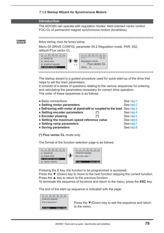
ADV200 • Quick start up guide - Specification and installation 79
7.1.2 Startup Wizard for Synchronous Motors
IntroductionThe ADV200 can operate with regulation modes: fi eld-oriented vector control FOC-CL of permanent magnet synchronous motors (brushless).
Note! Before starting, check the factory setting:
Menu 04 DRIVE CONFIG, parameter 04.2 Regulation mode, PAR: 552, default=Flux vector CL.
The startup wizard is a guided procedure used for quick start-up of the drive that helps to set the main parameters.It consists of a series of questions relating to the various sequences for entering and calculating the parameters necessary for correct drive operation. The order of these sequences is as follows:
● Basic connections See step 1● Setting motor parameters See step 2● Self-tuning with motor at stand-still or coupled to the load See step 3● Setting encoder parameters (*) See step 4● Encoder phasing (*) See step 5● Setting the maximum speed reference value See step 6● Setting ramp parameters See step 7● Saving parameters See step 8
(*) Flux vector CL mode only.
The format of the function selection page is as follows:
T+ T- EN LOC ILim n:0 AL
01 MONITOR
02 DRIVE INFO
03 STARTUP WIZARD
04 DRIVE CONFIG
T+ T- EN LOC ILim n:0 AL
STARTUP WIZARD
Set motor data ?
E=Yes Down=Next
Pressing the E key, the function to be programmed is accessed.Press the ▼ (Down) key to move to the next function skipping the current function.Press the ▲ key to return to the previous function.To terminate the sequence of functions and return to the menu, press the ESC key.
The end of the start-up sequence is indicated with the page:
T+ T- EN LOC ILim n:0 AL
STARTUP WIZARD
End of sequence !
Up=Back Down=Next
Press the ▼(Down) key to exit the sequence and return to the menu.
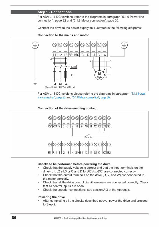
80 ADV200 • Quick start up guide - Specification and installation
Step 1 - ConnectionsFor ADV-...-4-DC versions, refer to the diagrams in paragraph “5.1.6 Power line connection”, page 32 and “5.1.8 Motor connection”, page 36.
Connect the drive to the power supply as illustrated in the following diagrams:
Connection to the mains and motor
L1 L2 L3 BR1 BR2 C D U V W
K1M
L1 L2 L3
F1
(3ph - 400 V / 460 V 50/60 Hz)AC AC,
M3 ph
For ADV-...-6-DC versions please refer to the diagrams in paragraph “5.1.6 Power line connection”, page 32 and “5.1.8 Motor connection”, page 36.
Connection of the drive enabling contact
R21R24 5 6 C1 7 8 9 10 11 12 C2 C3 S3
R11R14 1 2 3 4 S1+S1- 13 14 IS1 IC1 IC2 IS2
Enable
Checks to be performed before powering the drive• Check that the supply voltage is correct and that the input terminals on the
drive (L1, L2 e L3 or C and D for ADV-...-DC) are connected correctly.• Check that the output terminals on the drive (U, V, and W) are connected to
the motor correctly.• Check that all the drive control circuit terminals are connected correctly. Check
that all control inputs are open.• Check the encoder connections, see section A.3 of the Appendix. Powering the drive• After completing all the checks described above, power the drive and proceed
to Step 2.
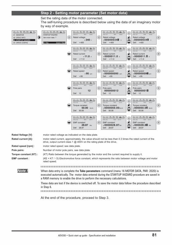
ADV200 • Quick start up guide - Specification and installation 81
Step 2 - Setting motor parameter (Set motor data)Set the rating data of the motor connected.The self-tuning procedure is described below using the data of an imaginary motor by way of example.
Rated Voltage [V]: motor rated voltage as indicated on the data plate.
Rated current [A]: motor rated current, approximately, the value should not be less than 0.3 times the rated current of the drive, output current class 1 @ 400V on the rating plate of the drive.
Rated speed [rpm] : motor rated speed; see data plate.
Pole pairs: Number of motor pole pairs, see data plate.
Torque constant (KT) : (KT) Ratio between the torque generated by the motor and the current required to supply it.
EMF constant : (KE = KT / √3) Electromotive force constant, which represents the ratio between motor voltage and motor rated speed.
Note ! When data entry is complete the Take parameters command (menu 16 MOTOR DATA, PAR: 2020) is executed automatically. The motor data entered during the STARTUP WIZARD procedure are saved in a RAM memory to enable the drive to perform the necessary calculations.
These data are lost if the device is switched off. To save the motor data follow the procedure described in Step 6.
At the end of the procedure, proceed to Step 3.
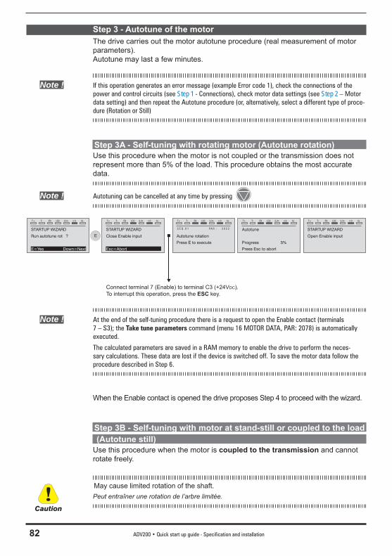
82 ADV200 • Quick start up guide - Specification and installation
Step 3 - Autotune of the motorThe drive carries out the motor autotune procedure (real measurement of motor parameters).Autotune may last a few minutes.
Note ! If this operation generates an error message (example Error code 1), check the connections of the power and control circuits (see Step 1 - Connections), check motor data settings (see Step 2 – Motor data setting) and then repeat the Autotune procedure (or, alternatively, select a different type of proce-dure (Rotation or Still)
Step 3A - Self-tuning with rotating motor (Autotune rotation)Use this procedure when the motor is not coupled or the transmission does not represent more than 5% of the load. This procedure obtains the most accurate data.
Note ! Autotuning can be cancelled at any time by pressing
T+ T- EN LOC ILim n:0 AL
STARTUP WIZARD
Run autotune rot ?
E=Yes Down=Next
E
T+ T- EN LOC ILim n:0 AL
STARTUP WIZARD
Close Enable input
Esc=Abort
T+ T- EN LOC ILim n:0 AL
Autotune rotation
S E Q . 0 1 PA R : 2 0 2 2
Press E to execute
T+ T- EN LOC ILim n:0 AL
Autotune
Press Esc to abort
Progress 5%
T+ T- EN LOC ILim n:0 AL
STARTUP WIZARD
Open Enable input
Connect terminal 7 (Enable) to terminal C3 (+24VDC). To interrupt this operation, press the ESC key.
Note ! At the end of the self-tuning procedure there is a request to open the Enable contact (terminals 7 – S3); the Take tune parameters command (menu 16 MOTOR DATA, PAR: 2078) is automatically executed.
The calculated parameters are saved in a RAM memory to enable the drive to perform the neces-sary calculations. These data are lost if the device is switched off. To save the motor data follow the procedure described in Step 6.
When the Enable contact is opened the drive proposes Step 4 to proceed with the wizard.
Step 3B - Self-tuning with motor at stand-still or coupled to the load (Autotune still)Use this procedure when the motor is coupled to the transmission and cannot rotate freely.
May cause limited rotation of the shaft.Peut entraîner une rotation de l’arbre limitée.
Caution

ADV200 • Quick start up guide - Specification and installation 83
Note ! Autotuning can be cancelled at any time by pressing
T+ T- EN LOC ILim n:0 AL
STARTUP WIZARD
Run autotune still ?
E=Yes Down=Next
E
T+ T- EN LOC ILim n:0 AL
STARTUP WIZARD
Close Enable input
Esc=Abort
T+ T- EN LOC ILim n:0 AL
Autotune still
S E Q . 0 1 PA R : 2 0 2 4
Press E to execute
T+ T- EN LOC ILim n:0 AL
Autotune
Press Esc to abort
Progress 5%
T+ T- EN LOC ILim n:0 AL
STARTUP WIZARD
Open Enable input
Connect terminal 7 (Enable) to terminal C3 (+24VDC)
Note ! At the end of the self-tuning procedure there is a request to open the Enable contact (terminals 7 – S3); the Take tune parameters command (menu 16 MOTOR DATA, PAR: 2078) is automatically executed.
The calculated parameters are saved in a RAM memory to enable the drive to perform the neces-sary calculations. These data are lost if the device is switched off. To save the motor data follow the procedure described in Step 6.
When the Enable contact is opened the drive proposes Step 4 to proceed with the wizard.
Step 4 - Setting encoder parameters
For Flux vector CL mode only (Menu 04 DRIVE CONFIG, parameter 04.2 Regu-lation mode, PAR: 552, default=Flux vector CL).
Note ! Optional card EXP-SESC-I1R1F2-ADL must be installed.
T+ T- EN LOC ILim n:0 AL
03 STARTUP WIZARD
Set encoder param?
E=Yes Down=Next
E
T+ T- EN LOC ILim n:0 AL
S E Q . 0 1 PA R : 2 1 0 0
Encoder resolution
2048 ppr
Def: 2048
E
E
T+ T- EN LOC ILim n:0 AL
S E Q . 0 1 PA R : 2 1 0 0
Full scale speed
ppr
Def: 2048
000002048
T+ T- EN LOC ILim n:0 AL
S E Q . 0 1 PA R : 2 1 0 0
Encoder resolution
000002048 ppr
Def: 2048
T+ T- EN LOC ILim n:0 AL
S E Q . 0 2 PA R : 2 1 0 2
Encoder supply
5.2 V
Def: 5.2
E
E
T+ T- EN LOC ILim n:0 AL
S E Q . 02 PA R : 2 1 0 2
Encoder supply
V
Def: 5.2
0000005.2
T+ T- EN LOC ILim n:0 AL
S E Q . 0 2 PA R : 2 1 0 2
Encoder supply
0000005.2 V
Def: 5.2
An incorrect encoder voltage setting could result in permanent damage to the device. Check the value on the encoder data plate.
Caution
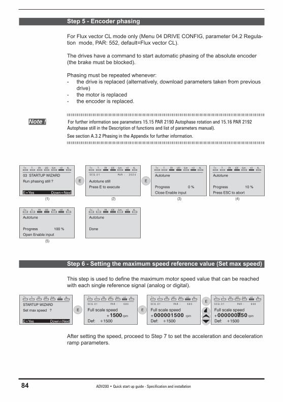
84 ADV200 • Quick start up guide - Specification and installation
Step 5 - Encoder phasing
For Flux vector CL mode only (Menu 04 DRIVE CONFIG, parameter 04.2 Regula-tion mode, PAR: 552, default=Flux vector CL).
The drives have a command to start automatic phasing of the absolute encoder (the brake must be blocked).
Phasing must be repeated whenever:- the drive is replaced (alternatively, download parameters taken from previous
drive)- the motor is replaced- the encoder is replaced.
Note ! For further information see parameters 15.15 PAR 2190 Autophase rotation and 15.16 PAR 2192 Autophase still in the Description of functions and list of parameters manual).
See section A.3.2 Phasing in the Appendix for further information.
T+ T- EN LOC ILim n:0 AL
03 STARTUP WIZARD
Run phasing still ?
E=Yes Down=Next
E
T+ T- EN LOC ILim n:0 AL
Autotune still
S E Q . 0 1 PA R : 2 0 2 4
Press E to execute
T+ T- EN LOC ILim n:0 AL
Autotune
Open Enable input
Progress 100 %
E
T+ T- EN LOC ILim n:0 AL
Autotune
Press ESC to abort
Progress 10 %
T+ T- EN LOC ILim n:0 AL
Autotune
Close Enable input
Progress 0 %
T+ T- EN LOC ILim n:0 AL
Autotune
Done
(1) (2) (3) (4)
(5)
Step 6 - Setting the maximum speed reference value (Set max speed)
This step is used to defi ne the maximum motor speed value that can be reached with each single reference signal (analog or digital).
T+ T- EN LOC ILim n:0 AL
STARTUP WIZARD
Set max speed ?
E=Yes Down=Next
E
T+ T- EN LOC ILim n:0 AL
S E Q . 0 1 PA R : 6 8 0
Full scale speed
+1500 rpm
Def: +1500
E
E
T+ T- EN LOC ILim n:0 AL
S E Q . 0 1 PA R : 6 8 0
Full scale speed
+ rpm
Def: +1500
000000750
T+ T- EN LOC ILim n:0 AL
S E Q . 0 1 PA R : 6 8 0
Full scale speed
+000001500 rpm
Def: +1500
After setting the speed, proceed to Step 7 to set the acceleration and deceleration ramp parameters.
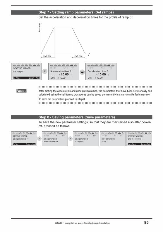
ADV200 • Quick start up guide - Specification and installation 85
Step 7 - Setting ramp parameters (Set ramps)Set the acceleration and deceleration times for the profi le of ramp 0 :
PAR: 700 PAR: 700
Fre
quency
T
T+ T- EN LOC ILim n:0 AL
STARTUP WIZARD
Set ramps ?
E=Yes Down=Next
E
T+ T- EN LOC ILim n:0 AL
S E Q . 0 1 PA R : 7 0 0
Acceleration time 0
+10.00 s
Def: +10.00
T+ T- EN LOC ILim n:0 AL
S E Q . 0 2 PA R : 7 0 2
Deceleration time 0
+10.00 s
Def: +10.00
Note ! After setting the acceleration and deceleration ramps, the parameters that have been set manually and calculated using the self-tuning procedures can be saved permanently in a non-volatile flash memory.
To save the parameters proceed to Step 8.
Step 8 - Saving parameters (Save parameters)To save the new parameter settings, so that they are maintained also after power-off, proceed as follows:
T+ T- EN LOC ILim n:0 AL
STARTUP WIZARD
Save parameters ?
E=Yes Down=Next
E
T+ T- EN LOC ILim n:0 AL
Save parameters
S E Q . 0 1 PA R : 5 5 0
Press E to execute
E
T+ T- EN LOC ILim n:0 AL
Save parameters
S E Q . 0 1 PA R : 5 5 0
In progress
T+ T- EN LOC ILim n:0 AL
Save parameters
S E Q . 0 1 PA R : 5 5 0
Done
T+ T- EN LOC ILim n:0 AL
STARTUP WIZARD
End of sequence !
Up=Back Down=Exit
86 ADV200 • Quick start up guide - Specification and installation
7.2 First customized start-upIn this section a startup test is performed, using a standard confi guration, to check drive functioning and command connections.A programming sequence has to be run to achieve a fi rst simple customisation in order to be able to set the drive for the requested application.
Note ! The main sections to be used, depending on the desired confi guration, are described below.
• Typical connection diagramsAuxiliary control circuits ________________________________ see chapter 5.6, fi gure 5.6.1Typical connection diagram, connection through terminals strip ___ see chapter 5.6, fi gure 5.6.2Potentials of the control section, Digital I/O PNP connection ______ see chapter 5.2.4, fi gure 5.2.4.1Other inputs connections (NPN-PNP) _______________________ see chapter 5.2.4, fi gure 5.2.4.2NPN outputs connection ________________________________ see chapter 5.2.4, fi gure 5.2.4.3
• Digital inputsThe table on chapter 5.2.3 shows the default settings for the analog and digital inputs and outputs.
Note ! Digital input settings can only be edited from the Expert parameters, see chapter 6.5.2.
7.2.1 For Asynchronous Motors• Selecting the regulation modeFirst set the regulation mode in the Regulation mode parameter (04 DRIVE CON-FIG menu, PAR: 552) :
0 V/f control. This is the simplest and least advanced control mode. This mode can also be used to control several motors connected in parallel using a single drive.
1 Open loop fi eld-oriented vector control (sensorless). In this mode, once the motor parameter self-tuning procedure has been performed, it is possible to create a mathematical model on which to perform all the necessary calcula-tions in order to obtain high performance levels, especially high motor torque levels, even at very low speeds without the use of feedback, and achieve signifi cant dynamic performance.
2 Closed loop fi eld-oriented vector control. This mode can be used to obtain maximum drive-motor effi ciency in terms of speed precision, dynamic system response and motor torque regulation. It requires feedback by a digital encod-er keyed to the motor shaft and connected to the relative optional expansion card mounted in the drive.
ADV200 • Quick start up guide - Specification and installation 87
• Selecting the type of referenceAfter setting the regulation mode, the source of the speed reference must be set in the Ramp ref 1 src parameter (05 REFERENCES menu, PAR: 610). This source can be selected from among those listed in the L_MLTREF selection list:
1 Analog input 1 mon parameter (PAR: 1500) to use the signal applied to terminals 1 – 2 of analog input 1 (14 - ANALOG INPUTS menu).
2 Dig ramp ref 1 parameter (05 - REFERENCES menu, PAR: 600) to set a digital speed inside the drive.
3 Multi ref out mon parameter (07 - MULTI REFERENCE menu, PAR: 852) to select the digital speeds using the digital inputs of the drive.
4 Mpot output mon parameter (08 - MOTOPOTENTIOMETER menu, PAR: 894) to use the internal motor potentiometer of the drive. If sending the com-mand from the operator keypad, to use the motor potentiometer function enter the Mpot setpoint parameter (PAR: 870) modify mode and press the Up (▲) and Down (▼) keys.
5 Jog output mon parameter (09 - JOG FUNCTION menu, PAR: 920) to use one of the drive’s internal jog speeds.
Signals from expansion cards, the serial line or fi eldbus can also be set as speed references (see the detailed description of parameters).
• Setting the type of analog referenceIf the analog input has been selected, choose the type of signal to use in the Ana-log inp 1 type parameter (14 - ANALOG INPUTS menu, PAR.1502): 0 ± 10V 1 0-20mA o 0-10V 2 4-20mAAs well as programming the Analog inp 1 type parameter (PAR:1502) you must also verify the position of the switches on the regulation card, as showed on chapter 5.2.4.
• Ramps settingThe acceleration and deceleration ramps can be set in Acceleration time 0 (06 - RAMPS menu, PAR: 700) and Deceleration time 0 (PAR: 702). The signal available on the analog input can be adjusted using Analog inp 1 scale parameter (14 - ANALOG INPUTS menu, PAR: 1504), An inp 1 offset tune parameter (PAR: 1506) and An inp 1 gain tune parameter (PAR: 1508).To use a digital speed to control the drive, enter it in the Dig ramp ref 1 parameter (05 - REFERENCES menu, PAR: 600). The ramps are the same used with the reference signal from the analog input.
• MultispeedTo use more than one digital speed, use the multi-speed function. First select the source of the speed signals Multi ref 0 src and Multi ref 1 src (07 - MULTI REFERENCE menu, PAR: 832 e 834) from the L_MLTREF selection list. Next defi ne which digital inputs are to perform switching between the various speeds; use the Multi ref sel .. src parameters (PAR: from 840 to 846) to select the signals to use from the L_DIGSEL2 selection list. Set the desired speeds in the Multi reference 0...7 parameters (PAR: from 800 to 814).
88 ADV200 • Quick start up guide - Specification and installation
Also in this case the ramps can be set in the Acceleration time 0 parameter (06 - RAMPS menu, PAR: 700) and Deceleration time 0 parameter (PAR: 702) parameters.
• Motor potentiometerTo use the motor potentiometer, the signals to increase or decrease the reference must be defi ned: set the Mpot up src parameter (08 - MOTOPOTENTIOMETER menu, PAR: 884) and Mpot down src parameter (PAR: 886) parameters respec-tively to increase and decrease the reference using selection list L_DIGSEL2. Set the motor potentiometer ramps using Mpot acceleration (PAR: 872) and Mpot deceleration parameters (PAR: 874).
• JogFinally, for Jog mode, select the control terminal in the Jog cmd + src parameter (09 - JOG FUNCTION menu, PAR: 916), using a signal from selection list L_DIG-SEL2. The Jog speed must be written in the Jog setpoint parameter (PAR: 910), while the acceleration and deceleration ramps can be set, respectively, in Jog accelera-tion (PAR: 912) and Jog deceleration parameters (PAR: 914).
• Speed limitsAfter selecting the reference, set the speed limits in the following parameters (05 - REFERENCES menu):- Full scale speed (PAR: 680). Setting of the maximum motor speed, which
usually coincides with the rated speed indicated on the motor data plate.- Speed ref top lim (PAR: 670). Upper speed limit: the maximum setting is
200% of the Full scale speed.- Speed ref bottom lim (PAR: 672). Lower speed limit: the maximum setting is
-200% of the Full scale speed.- Overspeed threshold (24 - ALARM CONFIG menu, PAR: 4540). Overspeed
alarm limit.
• Input and Output terminalsThe default setting of the input terminals is as follows:- Terminal 7 Digital input E Enable- Terminal 8 Digital input 1 FR forward src, PAR 1042- Terminal 9 Digital input 2 FR reverse src, PAR 1044- Terminal 10 Digital input 3 Multi ref sel 0 src- Terminal 11 Digital input 4 Multi ref sel 1 src- Terminal 12 Digital input 5 Fault reset src- Terminal S3 + 24V OUT I/O supply
The default confi guration of the terminals dedicated to digital outputs are as fol-lows:- Terminal R14 Digital output 1 Drive OK (Relay 1)- Terminal R11 COM Digital output 1 Common digital output 1 (Relay 1)- Terminal R24 Digital output 2 Drive ready (Relay 2)- Terminal R21 COM Digital output 2 Common digital output 2 (Relay 2)- Terminal 13 Digital output 3 Speed is 0 delay- Terminal IC1 COM Digital output 3/4 Common ref. for digital outputs 3 / 4- Terminal 14 Digital output 4 Ref is 0 delay- Terminal IS1 PS Digital output 3/4 Digital outputs 3 / 4 power supply
ADV200 • Quick start up guide - Specification and installation 89
Signals for the digital outputs can be programmed using the Digital output 1...4 src parameters (13 - DIGITAL OUTPUTS menu, PAR: from 1310 to 1316) using the settings in the L_DIGSEL1 selection list.
The drive also includes two analog outputs which are not factory-set. These outputs must be enabled by setting Analog out 1 src (15 - ANALOG OUTPUTS menu, PAR: 1800) and Analog out 2 src parameters (PAR: 1802) with a signal selected from selection list L_ANOUT. The signal available on analog output 1 is ± 10V, while the analog output 2 signal can be selected using the Analog out 2 type parameter (PAR: 1848) between: 0 0-20mA 1 4-20mA 2 ± 10V
The analog output signal can be adjusted using Analog out 1 scale (PAR: 1808) and Analog out 2 scale parameters (PAR:1810).
• KeypadUse the LOC / REM key with the Enable input open (terminal 7 on terminal strip T2) to control running, to stop and reverse the direction of rotation of the motor using the operator keypad on the drive. Use the potentiometer or an analog signal to control speed.For information on how to use a digital speed reference, see the example on chap-ter 7.3.3. The reference can have a positive or negative value, making it possible to reverse the direction of rotation of the motor.
When the Enable input is closed, to enable motor running press START. The mo-tor starts the acceleration ramp and moves to the speed set in the FWD direction. With the motor running you can adjust the speed using the Dig ramp ref 1 param-eter (PAR: 600) and the acceleration/deceleration ramps using Acceleration time 0 (PAR: 700) and Deceleration time 0 (PAR: 702).
To change the direction of rotation press FWD/REV.To stop the motor with the deceleration ramp, press STOP.If the Enable contact is opened the inverter bridge is immediately disabled and the motor stops for inertia
To return to control using the terminal strip commands and analog speed refer-ence:1. Stop the motor2. Open the Enable terminal3. Press LOC / REM key.
Note ! For more customizations and any information that is not included in this initial customization guide, see the description of the parameters in this manual.
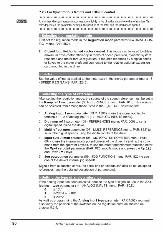
90 ADV200 • Quick start up guide - Specification and installation
7.2.2 For Synchronous Motors and FOC-CL control
Note ! At start-up, the synchronous motor may turn slightly in the direction opposite to that of rotation. This may depend on the parameter settings, the position of the rotor and the inertia/load applied.
• Selecting the regulation modeFirst set the regulation mode in the Regulation mode parameter (04 DRIVE CON-FIG menu, PAR: 552) :
2 Closed loop fi eld-oriented vector control. This mode can be used to obtain maximum drive-motor effi ciency in terms of speed precision, dynamic system response and motor torque regulation. It requires feedback by a digital encod-er keyed to the motor shaft and connected to the relative optional expansion card mounted in the drive.
• InertiaSet the value of inertia applied to the motor axis in the Inertia parameter (menu 18 - SPEED REG GAINS, PAR: 2240).
• Selecting the type of referenceAfter setting the regulation mode, the source of the speed reference must be set in the Ramp ref 1 src parameter (05 REFERENCES menu, PAR: 610). This source can be selected from among those listed in the L_MLTREF selection list:
1 Analog input 1 mon parameter (PAR: 1500) to use the signal applied to terminals 1 – 2 of analog input 1 (14 - ANALOG INPUTS menu).
2 Dig ramp ref 1 parameter (05 - REFERENCES menu, PAR: 600) to set a digital speed inside the drive.
3 Multi ref out mon parameter (07 - MULTI REFERENCE menu, PAR: 852) to select the digital speeds using the digital inputs of the drive.
4 Mpot output mon parameter (08 - MOTOPOTENTIOMETER menu, PAR: 894) to use the internal motor potentiometer of the drive. If sending the com-mand from the operator keypad, to use the motor potentiometer function enter the Mpot setpoint parameter (PAR: 870) modify mode and press the Up (▲) and Down (▼) keys.
5 Jog output mon parameter (09 - JOG FUNCTION menu, PAR: 920) to use one of the drive’s internal jog speeds.
Signals from expansion cards, the serial line or fi eldbus can also be set as speed references (see the detailed description of parameters).
• Setting the type of analog referenceIf the analog input has been selected, choose the type of signal to use in the Ana-log inp 1 type parameter (14 - ANALOG INPUTS menu, PAR.1502): 0 ± 10V 1 0-20mA o 0-10V 2 4-20mAAs well as programming the Analog inp 1 type parameter (PAR:1502) you must also verify the position of the switches on the regulation card, as showed on chapter 5.2.4.
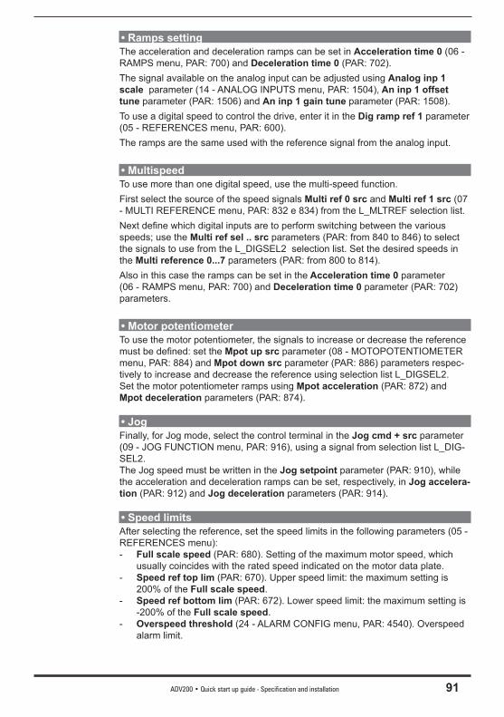
ADV200 • Quick start up guide - Specification and installation 91
• Ramps settingThe acceleration and deceleration ramps can be set in Acceleration time 0 (06 - RAMPS menu, PAR: 700) and Deceleration time 0 (PAR: 702). The signal available on the analog input can be adjusted using Analog inp 1 scale parameter (14 - ANALOG INPUTS menu, PAR: 1504), An inp 1 offset tune parameter (PAR: 1506) and An inp 1 gain tune parameter (PAR: 1508).To use a digital speed to control the drive, enter it in the Dig ramp ref 1 parameter (05 - REFERENCES menu, PAR: 600). The ramps are the same used with the reference signal from the analog input.
• MultispeedTo use more than one digital speed, use the multi-speed function. First select the source of the speed signals Multi ref 0 src and Multi ref 1 src (07 - MULTI REFERENCE menu, PAR: 832 e 834) from the L_MLTREF selection list. Next defi ne which digital inputs are to perform switching between the various speeds; use the Multi ref sel .. src parameters (PAR: from 840 to 846) to select the signals to use from the L_DIGSEL2 selection list. Set the desired speeds in the Multi reference 0...7 parameters (PAR: from 800 to 814). Also in this case the ramps can be set in the Acceleration time 0 parameter (06 - RAMPS menu, PAR: 700) and Deceleration time 0 parameter (PAR: 702) parameters.
• Motor potentiometerTo use the motor potentiometer, the signals to increase or decrease the reference must be defi ned: set the Mpot up src parameter (08 - MOTOPOTENTIOMETER menu, PAR: 884) and Mpot down src parameter (PAR: 886) parameters respec-tively to increase and decrease the reference using selection list L_DIGSEL2. Set the motor potentiometer ramps using Mpot acceleration (PAR: 872) and Mpot deceleration parameters (PAR: 874).
• JogFinally, for Jog mode, select the control terminal in the Jog cmd + src parameter (09 - JOG FUNCTION menu, PAR: 916), using a signal from selection list L_DIG-SEL2. The Jog speed must be written in the Jog setpoint parameter (PAR: 910), while the acceleration and deceleration ramps can be set, respectively, in Jog accelera-tion (PAR: 912) and Jog deceleration parameters (PAR: 914).
• Speed limitsAfter selecting the reference, set the speed limits in the following parameters (05 - REFERENCES menu):- Full scale speed (PAR: 680). Setting of the maximum motor speed, which
usually coincides with the rated speed indicated on the motor data plate.- Speed ref top lim (PAR: 670). Upper speed limit: the maximum setting is
200% of the Full scale speed.- Speed ref bottom lim (PAR: 672). Lower speed limit: the maximum setting is
-200% of the Full scale speed.- Overspeed threshold (24 - ALARM CONFIG menu, PAR: 4540). Overspeed
alarm limit.
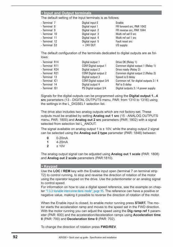
92 ADV200 • Quick start up guide - Specification and installation
• Input and Output terminalsThe default setting of the input terminals is as follows:- Terminal 7 Digital input E Enable- Terminal 8 Digital input 1 FR forward src, PAR 1042- Terminal 9 Digital input 2 FR reverse src, PAR 1044- Terminal 10 Digital input 3 Multi ref sel 0 src- Terminal 11 Digital input 4 Multi ref sel 1 src- Terminal 12 Digital input 5 Fault reset src- Terminal S3 + 24V OUT I/O supply
The default confi guration of the terminals dedicated to digital outputs are as fol-lows:- Terminal R14 Digital output 1 Drive OK (Relay 1)- Terminal R11 COM Digital output 1 Common digital output 1 (Relay 1)- Terminal R24 Digital output 2 Drive ready (Relay 2)- Terminal R21 COM Digital output 2 Common digital output 2 (Relay 2)- Terminal 13 Digital output 3 Speed is 0 delay- Terminal IC1 COM Digital output 3/4 Common ref. for digital outputs 3 / 4- Terminal 14 Digital output 4 Ref is 0 delay- Terminal IS1 PS Digital output 3/4 Digital outputs 3 / 4 power supply
Signals for the digital outputs can be programmed using the Digital output 1...4 src parameters (13 - DIGITAL OUTPUTS menu, PAR: from 1310 to 1316) using the settings in the L_DIGSEL1 selection list.
The drive also includes two analog outputs which are not factory-set. These outputs must be enabled by setting Analog out 1 src (15 - ANALOG OUTPUTS menu, PAR: 1800) and Analog out 2 src parameters (PAR: 1802) with a signal selected from selection list L_ANOUT. The signal available on analog output 1 is ± 10V, while the analog output 2 signal can be selected using the Analog out 2 type parameter (PAR: 1848) between: 0 0-20mA 1 4-20mA 2 ± 10V
The analog output signal can be adjusted using Analog out 1 scale (PAR: 1808) and Analog out 2 scale parameters (PAR:1810).
• KeypadUse the LOC / REM key with the Enable input open (terminal 7 on terminal strip T2) to control running, to stop and reverse the direction of rotation of the motor using the operator keypad on the drive. Use the potentiometer or an analog signal to control speed.For information on how to use a digital speed reference, see the example on chap-ter “7.3.3 Variable interconnections mode”, page 95. The reference can have a positive or negative value, making it possible to reverse the direction of rotation of the motor.
When the Enable input is closed, to enable motor running press START. The mo-tor starts the acceleration ramp and moves to the speed set in the FWD direction. With the motor running you can adjust the speed using the Dig ramp ref 1 param-eter (PAR: 600) and the acceleration/deceleration ramps using Acceleration time 0 (PAR: 700) and Deceleration time 0 (PAR: 702).
To change the direction of rotation press FWD/REV.

ADV200 • Quick start up guide - Specification and installation 93
To stop the motor with the deceleration ramp, press STOP.If the Enable contact is opened the inverter bridge is immediately disabled and the motor stops for inertia
To return to control using the terminal strip commands and analog speed refer-ence:1. Stop the motor2. Open the Enable terminal3. Press LOC / REM key.
Note ! For more customizations and any information that is not included in this initial customization guide, see the description of the parameters in this manual.
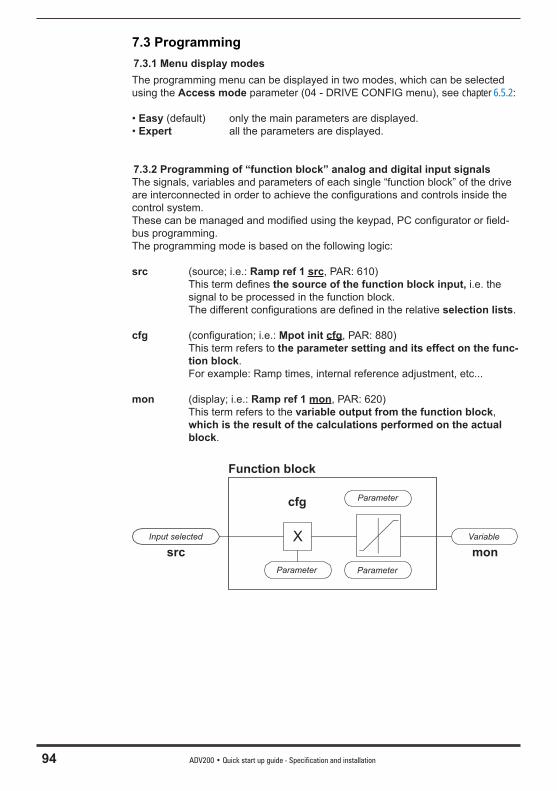
94 ADV200 • Quick start up guide - Specification and installation
7.3 Programming7.3.1 Menu display modesThe programming menu can be displayed in two modes, which can be selected using the Access mode parameter (04 - DRIVE CONFIG menu), see chapter 6.5.2:
• Easy (default) only the main parameters are displayed.• Expert all the parameters are displayed.
7.3.2 Programming of “function block” analog and digital input signalsThe signals, variables and parameters of each single “function block” of the drive are interconnected in order to achieve the confi gurations and controls inside the control system.These can be managed and modifi ed using the keypad, PC confi gurator or fi eld-bus programming.The programming mode is based on the following logic:
src (source; i.e.: Ramp ref 1 src, PAR: 610) This term defi nes the source of the function block input, i.e. the
signal to be processed in the function block. The different confi gurations are defi ned in the relative selection lists.
cfg (confi guration; i.e.: Mpot init cfg, PAR: 880) This term refers to the parameter setting and its effect on the func-
tion block. For example: Ramp times, internal reference adjustment, etc...
mon (display; i.e.: Ramp ref 1 mon, PAR: 620) This term refers to the variable output from the function block,
which is the result of the calculations performed on the actual block.
XInput selected
Parameter
Parameter
Parameter
Variable
cfg
src mon
Function block
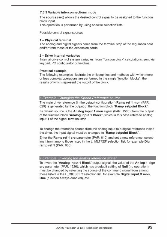
ADV200 • Quick start up guide - Specification and installation 95
7.3.3 Variable interconnections modeThe source (src) allows the desired control signal to be assigned to the function block input. This operation is performed by using specifi c selection lists.
Possible control signal sources:
1 – Physical terminalThe analog and digital signals come from the terminal strip of the regulation card and/or from those of the expansion cards.
2 – Drive internal variables Internal drive control system variables, from “function block” calculations, sent via keypad, PC confi gurator or fi eldbus.
Practical example The following examples illustrate the philosophies and methods with which more or less complex operations are performed in the single “function blocks”, the results of which represent the output of the block.
• Example: Changing the Speed Reference sourceThe main drive reference (in the default confi guration) Ramp ref 1 mon (PAR: 620) is generated by the output of the function block “Ramp setpoint Block”. Its default source is the Analog input 1 mon signal (PAR: 1500), from the output of the function block “Analog input 1 Block”, which in this case refers to analog input 1 of the signal terminal strip.
To change the reference source from the analog input to a digital reference inside the drive, the input signal must be changed to “Ramp setpoint Block”. Enter the Ramp ref 1 src parameter (PAR: 610) and set a new reference, select-ing it from among those listed in the L_MLTREF selection list, for example Dig ramp ref 1 (PAR: 600).
• Example: Inverting the analog reference signalTo invert the “Analog input 1 Block” output signal, the value of the An inp 1 sign src parameter (PAR: 1526), which has a default setting of Null (no operation), must be changed by selecting the source of the command signal from among those listed in the L_DIGSEL 2 selection list, for example Digital input X mon, One (function always enabled), etc.
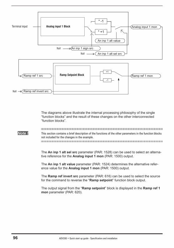
96 ADV200 • Quick start up guide - Specification and installation
+1
-1
* -1
* +1
Analog input 1 monAnalog input 1 Block
Ramp Setpoint Block
Null
Null
Terminal input
Ramp ref 1 monRamp ref 1 src
An inp 1 sign src
Null
An inp 1 alt value
An inp 1 alt sel src
Ramp ref invert src
The diagrams above illustrate the internal processing philosophy of the single “function blocks” and the result of these changes on the other interconnected “function blocks”.
Note ! This section contains a brief description of the functions of the other parameters in the function blocks not included for the changes in the example.
The An inp 1 alt sel src parameter (PAR: 1528) can be used to select an alterna-tive reference for the Analog input 1 mon (PAR: 1500) output.
The An inp 1 alt value parameter (PAR: 1524) determines the alternative refer-ence value for the Analog input 1 mon (PAR: 1500) output.
The Ramp ref invert src parameter (PAR: 616) can be used to select the source for the command to reverse the “Ramp setpoint” function block output.
The output signal from the “Ramp setpoint” block is displayed in the Ramp ref 1 mon parameter (PAR: 620).
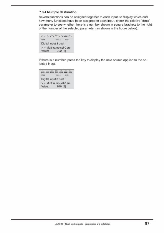
ADV200 • Quick start up guide - Specification and installation 97
7.3.4 Multiple destinationSeveral functions can be assigned together to each input: to display which and how many functions have been assigned to each input, check the relative “dest” parameter to see whether there is a number shown in square brackets to the right of the number of the selected parameter (as shown in the fi gure below).
T+ T- EN LOC ILim n:0 AL
12.09 PA R : 1 1 5 6
Digital input 3 dest
Value: 722 [1]>> Multi ramp sel 0 src
If there is a number, press the key to display the next source applied to the se-lected input.
T+ T- EN LOC ILim n:0 AL
12.09 PA R : 1 1 5 6
Digital input 3 dest
Value: 840 [2]>> Multi ramp sel 0 src
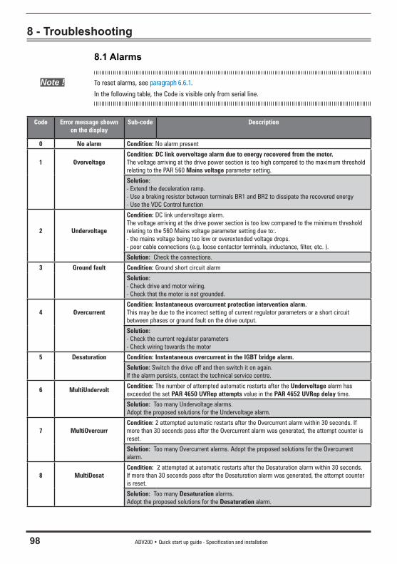
98 ADV200 • Quick start up guide - Specification and installation
8 - Troubleshooting
8.1 Alarms
Note ! To reset alarms, see paragraph 6.6.1.
In the following table, the Code is visible only from serial line.
Code Error message shown on the display
Sub-code Description
0 No alarm Condition: No alarm present
1 OvervoltageCondition: DC link overvoltage alarm due to energy recovered from the motor. The voltage arriving at the drive power section is too high compared to the maximum threshold relating to the PAR 560 Mains voltage parameter setting.
Solution: - Extend the deceleration ramp.- Use a braking resistor between terminals BR1 and BR2 to dissipate the recovered energy- Use the VDC Control function
2 Undervoltage
Condition: DC link undervoltage alarm. The voltage arriving at the drive power section is too low compared to the minimum threshold relating to the 560 Mains voltage parameter setting due to:.- the mains voltage being too low or overextended voltage drops.- poor cable connections (e.g. loose contactor terminals, inductance, filter, etc. ).
Solution: Check the connections.
3 Ground fault Condition: Ground short circuit alarm
Solution: - Check drive and motor wiring.- Check that the motor is not grounded.
4 OvercurrentCondition: Instantaneous overcurrent protection intervention alarm. This may be due to the incorrect setting of current regulator parameters or a short circuit between phases or ground fault on the drive output.
Solution: - Check the current regulator parameters- Check wiring towards the motor
5 Desaturation Condition: Instantaneous overcurrent in the IGBT bridge alarm.
Solution: Switch the drive off and then switch it on again. If the alarm persists, contact the technical service centre.
6 MultiUndervoltCondition: The number of attempted automatic restarts after the Undervoltage alarm has exceeded the set PAR 4650 UVRep attempts value in the PAR 4652 UVRep delay time.
Solution: Too many Undervoltage alarms. Adopt the proposed solutions for the Undervoltage alarm.
7 MultiOvercurrCondition: 2 attempted automatic restarts after the Overcurrent alarm within 30 seconds. If more than 30 seconds pass after the Overcurrent alarm was generated, the attempt counter is reset.
Solution: Too many Overcurrent alarms. Adopt the proposed solutions for the Overcurrent alarm.
8 MultiDesatCondition: 2 attempted at automatic restarts after the Desaturation alarm within 30 seconds. If more than 30 seconds pass after the Desaturation alarm was generated, the attempt counter is reset.
Solution: Too many Desaturation alarms. Adopt the proposed solutions for the Desaturation alarm.
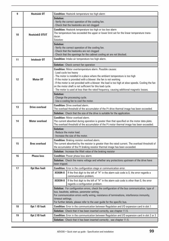
ADV200 • Quick start up guide - Specification and installation 99
9 Heatsink OT Condition: Heatsink temperature too high alarm
Solution: - Verify the correct operation of the cooling fan.- Check that the heatsinks are not clogged
10 HeatsinkS OTUT
Condition: Heatsink temperature too high or too low alarm The temperature has exceeded the upper or lower limit set for the linear temperature trans-ducer.Solution:
Solution: - Verify the correct operation of the cooling fan.- Check that the heatsinks are not clogged- Check that the openings for the cabinet cooling air are not blocked.
11 Intakeair OT Condition: Intake air temperature too high alarm.
Solution: Check correct fan operation
12 Motor OT
Condition: Motor overtemperature alarm. Possible causes:- Load cycle too heavy- The motor is installed in a place where the ambient temperature is too high- If the motor is provided with a blower: the fan is not working- If the motor is not provided with a blower: the load is too high at slow speeds. Cooling the fan on the motor shaft is not sufficient for this load cycle.- The motor is used at less than the rated frequency, causing additional magnetic losses.
Solution: - Change the processing cycle.- Use a cooling fan to cool the motor.
13 Drive overloadCondition: Drive overload alarm. The overload threshold of the accumulator of the I²t drive thermal image has been exceeded.
Solution: Check that the size of the drive is suitable for the application.
14 Motor overloadCondition: Motor overload alarm. The current absorbed during operation is greater than that specified on the motor data plate. The overload threshold of the accumulator of the I²t motor thermal image has been exceeded.
Solution: - Reduce the motor load.- Increase the size of the motor.
15 Bres overloadCondition: Braking resistor overload alarm. The current absorbed by the resistor is greater than the rated current. The overload threshold of the accumulator of the I²t braking resistor thermal image has been exceeded.
Solution: Increase the Watt value of the braking resistor
16 Phase loss Condition: Power phase loss alarm.
Solution: Check the mains voltage and whether any protections upstream of the drive have been tripped.
17 Opt Bus fault Condition: Error in the configuration stage or communication error.
XXX0H-X If the first digit to the left of “H” in the alarm sub-code is 0, the error regards a communication problem.
XXXXH-X If the first digit to the left of “H” in the alarm sub-code is other than 0, the error regards a configuration problem.
Solution: For configuration errors, check the configuration of the bus communication, type of bus, baudrate, address, parameter setting.For communication errors verify wiring, resistance of terminations, interference immunity, timeout settings.For further details, please refer to the user guide for the specific bus.
18 Opt 1 IO fault Condition: Error in the communication between Regulation and I/O expansion card in slot 1
Solution: Check that it has been inserted correctly, see chapter 11.5.
19 Opt 2 IO fault Condition: Error in the communication between Regulation and I/O expansion card in slot 2 or 3
Solution: Check that it has been inserted correctly , see chapter 11.5.
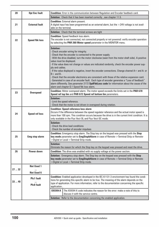
100 ADV200 • Quick start up guide - Specification and installation
20 Opt Enc fault Condition: Error in the communication between Regulation and Encoder feedback card.
Solution: Check that it has been inserted correctly , see chapter 11.5.
21 External faultCondition: External alarm present. A digital input has been programmed as an external alarm, but the +24V voltage is not avail-able on the terminal.
Solution: Check that the terminal screws are tight
22 Speed fbk lossCondition: Speed feedback loss alarm. The encoder is not connected, not connected properly or not powered: verify encoder operation by selecting the PAR 260 Motor speed parameter in the MONITOR menu.
Solution: - Check encoder wiring for integrity.- Check that the encoder is connected to the power supply.- With the drive disabled, turn the motor clockwise (seen from the motor shaft side). A positive value must be displayed.- If the value does not change or values are indicated randomly, check the encoder power sup-ply and cables.- If the value displayed is negative, invert the encoder connections. Change channel A+ and A- or B+ and B-.- Check that the encoder electronics are consistent with those of the relative expansion card.- Generated in case of an encoder fault. Each type of encoder generates a “Loss of feedback” alarm differently. See parameter 2172 SpdFbkLoss code for information about the cause of the alarm and chapter D.1 Speed fbk loss alarm.
23 OverspeedCondition: Motor overspeed alarm. The motor speed exceeds the limits set in the PAR 670 Speed ref top lim and PAR 672 Speed ref bottom lim parameters.
Solution: - Limit the speed reference.- Check that the motor is not driven in overspeed during rotation.
24 Speed ref loss
Condition: Speed reference loss alarmOccurs if the difference between the speed regulator reference and the actual motor speed is more than 100 rpm. This condition occurs because the drive is in the current limit condition. It is only available in the Flux Vect OL and Flux Vect OC mode.
Solution: - Check the drive load conditions- Check the number of encoder impulses
25 Emg stop alarmCondition: Emergency stop alarm. The Stop key on the keypad was pressed with the Stop key mode parameter set to EmgStop&Alarm in case of Remote->Terminal Strip or Remote->Digital or Local->Terminal Strip mode.
Solution: Eliminate the reason for which the Stop key on the keypad was pressed and reset the drive.
26 Power down Condition: The drive was enabled with no supply voltage at the power section.
Solution: Emergency stop alarm. The Stop key on the keypad was pressed with the Stop key mode parameter set to EmgStop&Alarm in case of Remote->Terminal Strip or Remote->Digital or Local->Terminal Strip mode.
27 ... 32Not Used 1
...Not Used 6
33 ... 40Plc1 fault
...Plc8 fault
Condition: Enabled application developed in the IEC 61131-3 environment has found the condi-tions for generating this specific alarm to be true. The meaning of the alarm depends on the type of application. For more information, refer to the documentation concerning the specific application..
XXXXH-X The XXXXH-X code indicates the reason for the error: make a note of this to discuss it with the service centre.
Solution: Refer to the documentation concerning the enabled application.
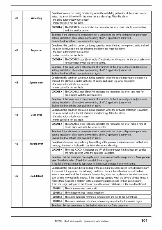
ADV200 • Quick start up guide - Specification and installation 101
41 Watchdog
Condition: may occur during functioning when the watchdog protection of the micro is acti-vated; the alarm is inserted in the alarm list and alarm log. After this alarm:- the drive automatically runs a reset- motor control is not available.
XXXXH-X The XXXXH-X code indicates the reason for the error: take note for examination with the service centre.
Solution: If the alarm was a consequence of a variation to the drive configuration (parameter setting, installation of an option, downloading of a PLC application), remove it.Switch the drive off and then switch it on again.
42 Trap error
Condition: this condition can occur during operation when the trap micro protection is enabled; the alarm is included in the list of alarms and alarm log. After this alarm:- the drive automatically runs a reset- motor control is not available.
XXXXH-X The XXXXH-X code (SubHandler-Class) indicates the reason for the error: take note for examination with the service centre.
Solution: If the alarm was a consequence of a variation to the drive configuration (parameter setting, installation of an option, downloading of a PLC application), remove it.Switch the drive off and then switch it on again.
43 System error
Condition: this condition can occur during operation when the operating system protection is enabled; the alarm is included in the list of alarms and alarm log. After this alarm:- the drive automatically runs a reset- motor control is not available.
XXXXH-X The XXXXH-X code (Error-Pid) indicates the reason for the error: take note for examination with the service centre.
Solution: If the alarm was a consequence of a variation to the drive configuration (parameter setting, installation of an option, downloading of a PLC application), remove it.Switch the drive off and then switch it on again.
44 User error
Condition: this condition can occur during operation when the software protection is enabled; the alarm is included in the list of alarms and alarm log. After this alarm:- the drive automatically runs a reset- motor control is not available.
XXXXH-X The XXXXH-X (Error-Pid) code indicates the reason for the error: make a note of this to discuss it with the service centre.
Solution: If the alarm was a consequence of a variation to the drive configuration (parameter setting, installation of an option, downloading of a PLC application), remove it.Switch the drive off and then switch it on again.
45 Param errorCondition: if an error occurs during the enabling of the parameter database saved in the Flash memory; the alarm is included in the list of alarms and alarm log.
XXXXH-X The code XXXXH-X indicates the IPA of the parameter that has been set outside the range allowed when the database is enabled.
Solution: Set the parameter causing the error to a value within the range and run Save param-eter. Switch the drive off and then switch it back on again.If the IPA of the parameter is not shown in the manual, contact the service centre.
46 Load default
Condition: this can occur during loading of the parameter database saved in the Flash memoryit is normal if it appears in the following conditions: the first time the drive is switched on, when a new version of the firmware is downloaded, when the regulation is installed on a new size, when a new region is entered. If this message appears when the drive is already in use it means there has been a problem in the parameter database saved in the Flash memory.If this message is displayed the drive restores the default database, i.e. the one downloaded.
0001H-1 The database saved is not valid
0002H-2 The database saved is not compatible
0003H-3 The saved database refers to a different size and not to the current size
0004H-4 The saved database refers to a different region and not to the current region
Solution: Set the parameters to the desired value and run Save parameter
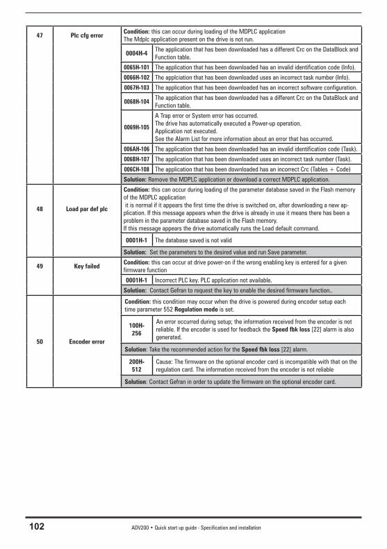
102 ADV200 • Quick start up guide - Specification and installation
47 Plc cfg errorCondition: this can occur during loading of the MDPLC applicationThe Mdplc application present on the drive is not run.
0004H-4The application that has been downloaded has a different Crc on the DataBlock and Function table.
0065H-101 The application that has been downloaded has an invalid identification code (Info).
0066H-102 The applciation that has been downloaded uses an incorrect task number (Info).
0067H-103 The application that has been downloaded has an incorrect software configuration.
0068H-104The application that has been downloaded has a different Crc on the DataBlock and Function table.
0069H-105
A Trap error or System error has occurred.The drive has automatically executed a Power-up operation.Application not executed.See the Alarm List for more information about an error that has occurred.
006AH-106 The application that has been downloaded has an invalid identification code (Task).
006BH-107 The application that has been downloaded uses an incorrect task number (Task).
006CH-108 The application that has been downloaded has an incorrect Crc (Tables + Code)
Solution: Remove the MDPLC application or download a correct MDPLC application.
48 Load par def plc
Condition: this can occur during loading of the parameter database saved in the Flash memory of the MDPLC application it is normal if it appears the first time the drive is switched on, after downloading a new ap-plication. If this message appears when the drive is already in use it means there has been a problem in the parameter database saved in the Flash memory.If this message appears the drive automatically runs the Load default command.
0001H-1 The database saved is not valid
Solution: Set the parameters to the desired value and run Save parameter.
49 Key failedCondition: this can occur at drive power-on if the wrong enabling key is entered for a given firmware function
0001H-1 Incorrect PLC key. PLC application not available.
Solution: Contact Gefran to request the key to enable the desired firmware function..
50 Encoder error
Condition: this condition may occur when the drive is powered during encoder setup each time parameter 552 Regulation mode is set.
100H-256
An error occurred during setup; the information received from the encoder is not reliable. If the encoder is used for feedback the Speed fbk loss [22] alarm is also generated.
Solution: Take the recommended action for the Speed fbk loss [22] alarm.
200H-512
Cause: The firmware on the optional encoder card is incompatible with that on the regulation card. The information received from the encoder is not reliable
Solution: Contact Gefran in order to update the firmware on the optional encoder card.
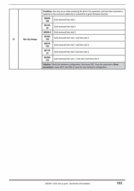
ADV200 • Quick start up guide - Specification and installation 103
51 Opt cfg change
Condition: this may occur when powering the drive if an expansion card has been removed or replaced or the incorrect enable key is inserted for a given firmware function.
0064H-100
Card removed from slot 1.
0014H-20
Card removed from slot 2
0003H-3 Card removed from slot 3
0078H-120
Card removed from slot 1 and from slot 2
0067H-103
Card removed from slot 1 and from slot 3.
0017H-23
Card removed from slot 2 and from slot 3.
007BH-123
Card removed from slot 1, from slot 2 and from slot 3
Solution: Check the hardware configuration, then press ESC. Save the parameters (Save parameters, menu 04.01 par 550) to save the new hardware configuration.
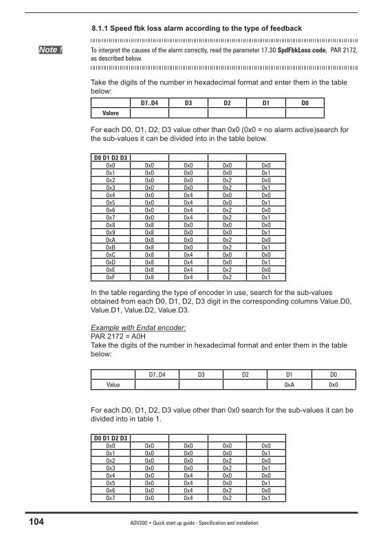
104 ADV200 • Quick start up guide - Specification and installation
8.1.1 Speed fbk loss alarm according to the type of feedback
Note ! To interpret the causes of the alarm correctly, read the parameter 17.30 SpdFbkLoss code, PAR 2172, as described below.
Take the digits of the number in hexadecimal format and enter them in the table below:
D7..D4 D3 D2 D1 D0
Valore For each D0, D1, D2, D3 value other than 0x0 (0x0 = no alarm active)search for the sub-values it can be divided into in the table below.
D0 D1 D2 D30x0 0x0 0x0 0x0 0x00x1 0x0 0x0 0x0 0x10x2 0x0 0x0 0x2 0x00x3 0x0 0x0 0x2 0x10x4 0x0 0x4 0x0 0x00x5 0x0 0x4 0x0 0x10x6 0x0 0x4 0x2 0x00x7 0x0 0x4 0x2 0x10x8 0x8 0x0 0x0 0x00x9 0x8 0x0 0x0 0x10xA 0x8 0x0 0x2 0x00xB 0x8 0x0 0x2 0x10xC 0x8 0x4 0x0 0x00xD 0x8 0x4 0x0 0x10xE 0x8 0x4 0x2 0x00xF 0x8 0x4 0x2 0x1
In the table regarding the type of encoder in use, search for the sub-values obtained from each D0, D1, D2, D3 digit in the corresponding columns Value.D0, Value.D1, Value.D2, Value.D3.
Example with Endat encoder:PAR 2172 = A0HTake the digits of the number in hexadecimal format and enter them in the table below:
D7..D4 D3 D2 D1 D0
Value 0xA 0x0
For each D0, D1, D2, D3 value other than 0x0 search for the sub-values it can be divided into in table 1.
D0 D1 D2 D30x0 0x0 0x0 0x0 0x00x1 0x0 0x0 0x0 0x10x2 0x0 0x0 0x2 0x00x3 0x0 0x0 0x2 0x10x4 0x0 0x4 0x0 0x00x5 0x0 0x4 0x0 0x10x6 0x0 0x4 0x2 0x00x7 0x0 0x4 0x2 0x1

ADV200 • Quick start up guide - Specification and installation 105
0x8 0x8 0x0 0x0 0x00x9 0x8 0x0 0x0 0x10xA 0x8 0x0 0x2 0x00xB 0x8 0x0 0x2 0x10xC 0x8 0x4 0x0 0x00xD 0x8 0x4 0x0 0x10xE 0x8 0x4 0x2 0x00xF 0x8 0x4 0x2 0x1
For each D0, D1, D2, D3 value other than 0x0 search for the sub-values it can be divided into in table 1.
In the table regarding the type of encoder in use, search for the sub-values obtained from each D0, D1, D2, D3 digit in the corresponding columns Value.D0, Value.D1, Value.D2, Value.D3
Value.D1 = 2H Cause: (CRC_CKS_P)disturbed SSI signals cause a CKS error or Parity.
Valore.D1 = 8H Causa: (DT1_ERR) ECause: (DT1_ERR) Encoder has detected a malfunction and signals this to the dri-ve via Error bit. Bits 16..31 contain the type of malfunction detected by the encoder.
● Speed fbk loss [22] alarm with digital incremental encoder
BitValue
NameDescription
D7..D4 D3 D2 D1 D0
0 0x1 CHA Cause: no impulses or disturbance on incremental channel A.
Solution: Check the connection of the encoder-drive channel A, check the connection of the screen, check the encoder supply voltage.Check parameters 2102 Encoder 1 supply and 2104 Encoder 1 input cfg (if encoder 1 is used).Check parameters 5102 Encoder 2 supply and 5104 Encoder 2 input cfg (if encoder 2 is used).
1 0x2 CHB Cause: no impulses or disturbance on incremental channel B.
Solution: Check the connection of the encoder-drive channel B, check the connection of the screen, check the Encoder 1 supply voltage.Check parameters 2102 Encoder 1 supply and 2104 Encoder 1 input cfg (if encoder 1 is used).Check parameters 5102 Encoder 2 supply and 5104 Encoder 2 input cfg (if encoder 2 is used).
2 0x4 CHZ Cause: no impulses or disturbance on incremental channel Z.
Solution: Check the connection of the encoder-drive channel Z, check the connection of the screen, check the Encoder 1 supply voltage.Check parameters 2102 Encoder 1 supply and 2104 Encoder 1 input cfg (if encoder 1 is used).Check parameters 5102 Encoder 2 supply and 5104 Encoder 2 input cfg (if encoder 2 is used).
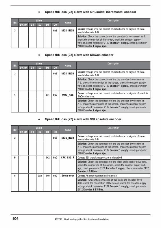
106 ADV200 • Quick start up guide - Specification and installation
● Speed fbk loss [22] alarm with sinusoidal incremental encoder
BitValue
NameDescription
D7..D4 D3 D2 D1 D0
3 0x8 MOD_INCRCause: voltage level not correct or disturbance on signals of incre-mental channels A-B.
Solution: Check the connection of the encoder-drive channels A-B, check the connection of the screen, check the encoder supply voltage, check parameter 2102 Encoder 1 supply, check parameter 2108 Encoder 1 signal Vpp.
● Speed fbk loss [22] alarm with SinCos encoder
BitValue
NameDescription
D7..D4 D3 D2 D1 D0
3 0x8 MOD_INCRCause: voltage level not correct or disturbance on signals of incre-mental channels A-B.
Solution: Check the connection of the the encoder-drive channels A-B, check the connection of the screen, check the encoder supply voltage, check parameter 2102 Encoder 1 supply, check parameter 2108 Encoder 1 signal Vpp.
4 0x1 0x0 MOD_ABSCause: voltage level not correct or disturbance on signals of absolute SinCos channels.
Solution: Check the connection of the the encoder-drive channels A-B, check the connection of the screen, check the encoder supply voltage, check parameter 2102 Encoder 1 supply, check parameter 2108 Encoder 1 signal Vpp.
● Speed fbk loss [22] alarm with SSI absolute encoder
BitValue
NameDescription
D7..D4 D3 D2 D1 D0
3 0x8 MOD_INCRCause: voltage level not correct or disturbance on signals of incre-mental channels A-B.
Solution: Check the connection of the the encoder-drive channels A-B, check the connection of the screen, check the encoder supply voltage, check parameter 2102 Encoder 1 supply, check parameter 2108 Encoder 1 signal Vpp.
5 0x2 0x0 CRC_CKS_P Cause: SSI signals not present or disturbed.
Solution: Check the connection of the clock and encoder-drive data, check the connection of the screen, check the encoder supply volt-age, check parameter 2102 Encoder 1 supply, check parameter 2112 Encoder 1 SSI bits.
8 0x1 0x0 0x0 Setup error Cause: An error occurred during setup.
Solution: Check the connection of the clock and encoder-drive data, check the connection of the screen, check the encoder supply voltage, check parameter 2102 Encoder 1 supply, check parameter 2112 Encoder 1 SSI bits.
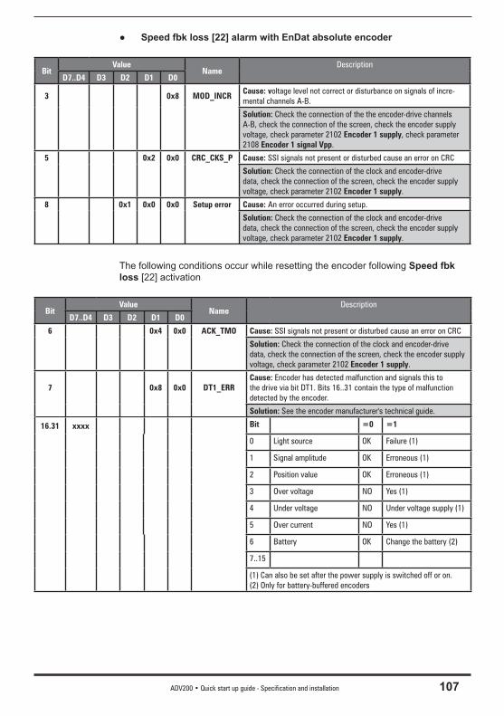
ADV200 • Quick start up guide - Specification and installation 107
● Speed fbk loss [22] alarm with EnDat absolute encoder
BitValue
NameDescription
D7..D4 D3 D2 D1 D0
3 0x8 MOD_INCRCause: voltage level not correct or disturbance on signals of incre-mental channels A-B.
Solution: Check the connection of the the encoder-drive channels A-B, check the connection of the screen, check the encoder supply voltage, check parameter 2102 Encoder 1 supply, check parameter 2108 Encoder 1 signal Vpp.
5 0x2 0x0 CRC_CKS_P Cause: SSI signals not present or disturbed cause an error on CRC
Solution: Check the connection of the clock and encoder-drive data, check the connection of the screen, check the encoder supply voltage, check parameter 2102 Encoder 1 supply.
8 0x1 0x0 0x0 Setup error Cause: An error occurred during setup.
Solution: Check the connection of the clock and encoder-drive data, check the connection of the screen, check the encoder supply voltage, check parameter 2102 Encoder 1 supply.
The following conditions occur while resetting the encoder following Speed fbk loss [22] activation
BitValue
NameDescription
D7..D4 D3 D2 D1 D0
6 0x4 0x0 ACK_TMO Cause: SSI signals not present or disturbed cause an error on CRC
Solution: Check the connection of the clock and encoder-drive data, check the connection of the screen, check the encoder supply voltage, check parameter 2102 Encoder 1 supply.
7 0x8 0x0 DT1_ERRCause: Encoder has detected malfunction and signals this to the drive via bit DT1. Bits 16..31 contain the type of malfunction detected by the encoder.
Solution: See the encoder manufacturer's technical guide.
16.31 xxxx Bit =0 =1
0 Light source OK Failure (1)
1 Signal amplitude OK Erroneous (1)
2 Position value OK Erroneous (1)
3 Over voltage NO Yes (1)
4 Under voltage NO Under voltage supply (1)
5 Over current NO Yes (1)
6 Battery OK Change the battery (2)
7..15
(1) Can also be set after the power supply is switched off or on.(2) Only for battery-buffered encoders
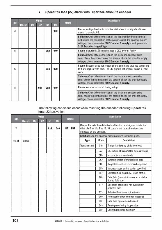
108 ADV200 • Quick start up guide - Specification and installation
● Speed fbk loss [22] alarm with Hiperface absolute encoder
BitValue
NameDescription
D7..D4 D3 D2 D1 D0
3 0x8Cause: voltage level not correct or disturbance on signals of incre-mental channels A-B.
Solution: Check the connection of the the encoder-drive channels A-B, check the connection of the screen, check the encoder supply voltage, check parameter 2102 Encoder 1 supply, check parameter 2108 Encoder 1 signal Vpp.
5 0x2 0x0 Cause: disturbed SSI signals cause a CKS error or Parity
Solution: Check the connection of the clock and encoder-drive data, check the connection of the screen, check the encoder supply voltage, check parameter 2102 Encoder 1 supply.
6 0x4 0x0Cause: Encoder does not recognise the command that has been sent to it and replies with ACK. The SSI signals not present cause a TMO error.
Solution: Check the connection of the clock and encoder-drive data, check the connection of the screen, check the encoder supply voltage, check parameter 2102 Encoder 1 supply.
8 0x1 0x0 0x0 Cause: An error occurred during setup.
Solution: Check the connection of the clock and encoder-drive data, check the connection of the screen, check the encoder supply voltage, check parameter 2102 Encoder 1 supply.
The following conditions occur while resetting the encoder following Speed fbk loss [22] activation.
BitValue
NameDescription
D7..D4 D3 D2 D1 D0
7 0x8 0x0 DT1_ERRCause: Encoder has detected malfunction and signals this to the drive via Error bit. Bits 16..31 contain the type of malfunction detected by the encoder.
Solution: See the encoder manufacturer's technical guide.
16.31 xxxx Type Code Description
Transmission 09h Transmitted parity bit is incorrect
0AH Checksum of transmitted data is wrong
0BH Incorrect command code
0CH Wrong number of transmitted data
0DH Illegal transmitted command argument
0FH Wrong access authorization specified
0EH Selected field has READ ONLY status
10H Data field (re) definition not executable due to field size
11H Specified address is not available in selected field
12H Selected field does not yet exist
00H No encoder error, no error message
03H Data field operations disabled
04H Analog monitoring inoperative
08H Counting register overflow
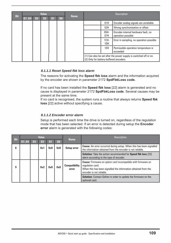
ADV200 • Quick start up guide - Specification and installation 109
BitValue
NameDescription
D7..D4 D3 D2 D1 D0
01H Encoder analog signals are unreliable
02H Wrong synchronisation or offset
05H-07H
Encoder-internal hardware fault, no operation possible
1CH-1DH
Error in sampling, no operation possible
1EH Permissible operation temperature is exceeded
(1) Can also be set after the power supply is switched off or on.(2) Only for battery-buffered encoders
8.1.1.1 Reset Speed fbk loss alarmThe reasons for activating the Speed fbk loss alarm and the information acquired by the encoder are shown in parameter 2172 SpdFbkLoss code.
If no card has been installed the Speed fbk loss [22] alarm is generated and no cause is displayed in parameter 2172 SpdFbkLoss code. Several causes may be present at the same time.If no card is recognised, the system runs a routine that always returns Speed fbk loss [22] active without specifying a cause.
8.1.1.2 Encoder error alarmSetup is performed each time the drive is turned on, regardless of the regulation mode that has been selected. If an error is detected during setup the Encoder error alarm is generated with the following codes:
BitValue
NameDescription
D7..D4 D3 D2 D1 D0
8 0x1 0x0 0x0 Setup errorCause: An error occurred during setup. When this has been signalled the information obtained from the encoder is not reliable.
Solution: Take the action recommended for Speed fbk loss [22] alarm according to the type of encoder.
9 0x2 0x0 0x0Compatibility
error
Cause: Firmware on option card incompatible with firmware on regulation card.When this has been signalled the information obtained from the encoder is not reliable.
Solution: Contact Gefran in order to update the firmware on the optional card.
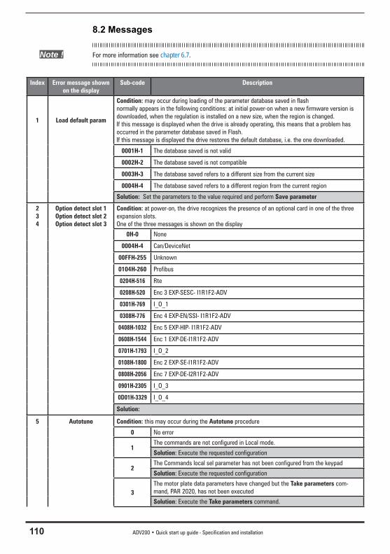
110 ADV200 • Quick start up guide - Specification and installation
8.2 Messages
Note ! For more information see chapter 6.7.
Index Error message shown on the display
Sub-code Description
1 Load default param
Condition: may occur during loading of the parameter database saved in flashnormally appears in the following conditions: at initial power-on when a new firmware version is downloaded, when the regulation is installed on a new size, when the region is changed.If this message is displayed when the drive is already operating, this means that a problem has occurred in the parameter database saved in Flash.If this message is displayed the drive restores the default database, i.e. the one downloaded.
0001H-1 The database saved is not valid
0002H-2 The database saved is not compatible
0003H-3 The database saved refers to a different size from the current size
0004H-4 The database saved refers to a different region from the current region
Solution: Set the parameters to the value required and perform Save parameter
234
Option detect slot 1Option detect slot 2Option detect slot 3
Condition: at power-on, the drive recognizes the presence of an optional card in one of the three expansion slots.One of the three messages is shown on the display
0H-0 None
0004H-4 Can/DeviceNet
00FFH-255 Unknown
0104H-260 Profibus
0204H-516 Rte
0208H-520 Enc 3 EXP-SESC- I1R1F2-ADV
0301H-769 I_O_1
0308H-776 Enc 4 EXP-EN/SSI- I1R1F2-ADV
0408H-1032 Enc 5 EXP-HIP- I1R1F2-ADV
0608H-1544 Enc 1 EXP-DE-I1R1F2-ADV
0701H-1793 I_O_2
0108H-1800 Enc 2 EXP-SE-I1R1F2-ADV
0808H-2056 Enc 7 EXP-DE-I2R1F2-ADV
0901H-2305 I_O_3
0D01H-3329 I_O_4
Solution:
5 Autotune Condition: this may occur during the Autotune procedure
0 No error
1The commands are not configured in Local mode.
Solution: Execute the requested configuration
2The Commands local sel parameter has not been configured from the keypad
Solution: Execute the requested configuration
3The motor plate data parameters have changed but the Take parameters com-mand, PAR 2020, has not been executed
Solution: Execute the Take parameters command.
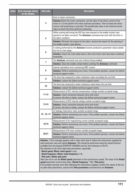
ADV200 • Quick start up guide - Specification and installation 111
Index Error message shown on the display
Sub-code Description
4
Error in motor connection.
Solution:Check the motor connection, set the value of the direct current of the motor to 1/3 and perform the motor autotune procedure. Then increase the direct current until autotuning is executed. The penultimate value is the nominal current value at which the drive performs autotuning.
5
While running self-tuning the ESC key was pressed or the enable contact was opened or an alarm occurred. The Autotune command was sent with the drive in the alarm condition
Solution: Eliminate the reason for the alarm, remove the reason for the opening of the enable contact, reset alarms.
6
A setting performed by the Autotune function produced a parameter value outside the min or max range.
Solution: Check the motor plate data or drive and motor sizes have been combined incorrectly.
7The Autotune command was sent without being enabled.
Solution: Close the enable contact before sending the Autotune command
8Internal calculation error concerning IGBT control
Solution: Perform autotuning once more, if the problem persists, contact the Gefran technical support centre.
9The drive has measured a stator resistance value exceeding the set limit.
Solution: contact the Gefran technical support centre.
10The drive has measured a stator resistance value below the set limit.
Solution: contact the Gefran technical support centre.
11-12Measurement of DTL internal compensation voltage outside accepted range.
Solution: check connection between drive and motor.If correct, the drive is faulty, contact the Gefran technical support centre.
13-14Measurement of DTS internal voltage outside accepted range.
Solution: check connection between drive and motor.If correct, the drive is faulty, contact the Gefran technical support centre.
15 - 16 -17LS leakage inductance value outside accepted range.
Solution: Perform autotuning once more, if the problem persists, contact the Gefran technical support centre.
18-19Measurement of Im magnetising current outside accepted range.
Solution: Perform autotuning once more, if the problem persists, contact the Gefran technical support centre.
20-21Measurement of Rr rotor resistor outside accepted range.
Solution: Perform autotuning once more, if the problem persists, contact the Gefran technical support centre.
Solution: If the message appears with a value other than 0, follow the instructions supplied for each particular case and repeat Autotune. This should be performed using the wizard function available from the keypad (STARTUP WIZARD) and the Tool software on the PC.Pay attention to all motor plate data parmaeters, especially:- Rated speed, Motor rated speed in rpm. - Rated frequency, Motor rated frequency in Hz- Pole pairs, Motor pole pairsTake care not to set the Rated speed parameter to the synchronous speed. The value of the Rated speed parameter must be less than: [(Rated frequency * 60) / Pole pairs].If the problem persists even after following the instructions supplied, confirm the values of the mo-tor plate data parameters, execute the Take parameters command but not Autotune.
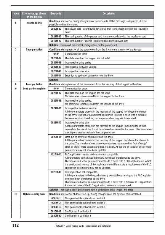
112 ADV200 • Quick start up guide - Specification and installation
Index Error message shown on the display
Sub-code Description
6 Power configCondition: may occur during recognition of power cards. If this message is displayed, it is not possible to drive the motor.
0020H-32 The power card is configured for a drive that is incompatible with the regulation card
0021H-33 The configuration of the power card is not compatible with the regulation card
0017H-23 The configuration required is not available on the power card
Solution: Download the correct configuration on the power card
7 Save par failed Condition: during transfer of the parameters from the drive to the memory of the keypad
0H-0 Communication error
0025H-37 The data saved on the keypad are not valid
0026H-38 Incompatible drive series
0027H-39 Incompatible software version
0028H-40 Incompatible drive size
0029H-41 Error during saving of parameters on the drive
Solution:
8 Load par failed Condition: during transfer of the parameters from the memory of the keypad to the drive
9 Load par incomplete 0H-0 Communication error
0025H-37 The data saved on the keypad are not valid. No parameter is transferred from the keypad to the drive
0026H-38 Incompatible drive series.No parameter is transferred from the keypad to the drive
0027H-39 Incompatible software version.All the parameters present in the memory of the keypad have been transferred to the drive. The set of parameters transferred refers to a drive with a different firmware version; therefore, certain parameters may not be updated.
0028H-40 Incompatible drive size.All the parameters present in the memory of the keypad (excluding those that depend on the size of the drive), have been transferred to the drive. The parameters that depend on size maintain their original value.
0029H-41 Error during saving of parameters on the drive.All the parameters present in the memory of the keypad have been transferred to the drive. The transfer of one or more parameters has caused an “out of range” error, or one or more parameters does not exist. At the end of transfer, one or more parameters may not have been updated.
002AH-42 PLC application release and version not compatible.All parameters in the keypad memory have been transferred to the drive.The transferred set of parameters relates to a drive with a PLC application in which the version and release of the application are different. As a result some of the PLC application parameters may not be updated.
002BH-43 PLC application not compatible.All the parameters in the keypad memory except those relating to the PLC applcia-tion have been transferred to the drive.The transferred set of parameters relates to a drive with a different PLC application. As a result none of the PLC application parameters are updated.
Solution: Recover a set of parameters from a compatible drive (model and size)
10 Options config error Condition: may occur at drive start-up, during recognition of the optional cards installed
0001H-1 Non-permissible optional card in slot 1
0002H-2 Non-permissible optional card in slot 2
0004H-4 Non-permissible optional card in slot 3
0010H-16 Conflict slot 1 with slot 2
0020H-32 Conflict slot 1 with slot 3
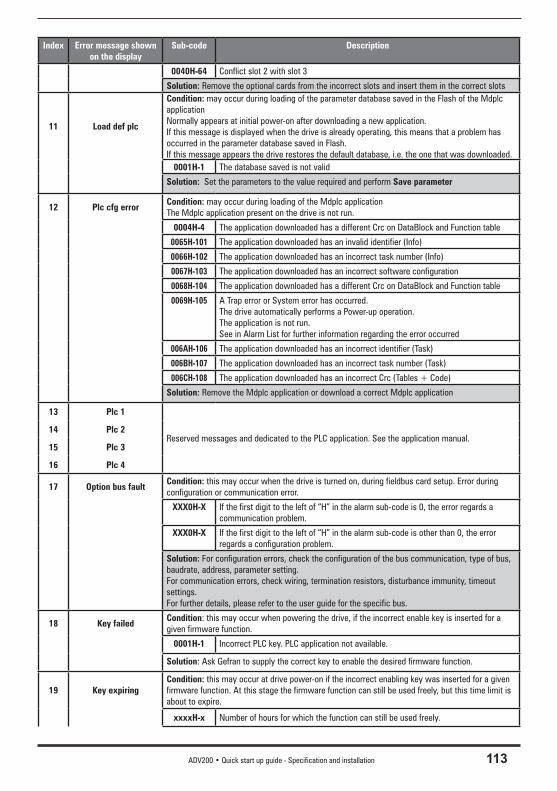
ADV200 • Quick start up guide - Specification and installation 113
Index Error message shown on the display
Sub-code Description
0040H-64 Conflict slot 2 with slot 3
Solution: Remove the optional cards from the incorrect slots and insert them in the correct slots
11 Load def plc
Condition: may occur during loading of the parameter database saved in the Flash of the Mdplc applicationNormally appears at initial power-on after downloading a new application.If this message is displayed when the drive is already operating, this means that a problem has occurred in the parameter database saved in Flash.If this message appears the drive restores the default database, i.e. the one that was downloaded.
0001H-1 The database saved is not valid
Solution: Set the parameters to the value required and perform Save parameter
12 Plc cfg errorCondition: may occur during loading of the Mdplc applicationThe Mdplc application present on the drive is not run.
0004H-4 The application downloaded has a different Crc on DataBlock and Function table
0065H-101 The application downloaded has an invalid identifier (Info)
0066H-102 The application downloaded has an incorrect task number (Info)
0067H-103 The application downloaded has an incorrect software configuration
0068H-104 The application downloaded has a different Crc on DataBlock and Function table
0069H-105 A Trap error or System error has occurred.The drive automatically performs a Power-up operation.The application is not run. See in Alarm List for further information regarding the error occurred
006AH-106 The application downloaded has an incorrect identifier (Task)
006BH-107 The application downloaded has an incorrect task number (Task)
006CH-108 The application downloaded has an incorrect Crc (Tables + Code)
Solution: Remove the Mdplc application or download a correct Mdplc application
13 Plc 1
Reserved messages and dedicated to the PLC application. See the application manual.14 Plc 2
15 Plc 3
16 Plc 4
17 Option bus faultCondition: this may occur when the drive is turned on, during fieldbus card setup. Error during configuration or communication error.
XXX0H-X If the first digit to the left of “H” in the alarm sub-code is 0, the error regards a communication problem.
XXX0H-X If the first digit to the left of “H” in the alarm sub-code is other than 0, the error regards a configuration problem.
Solution: For configuration errors, check the configuration of the bus communication, type of bus, baudrate, address, parameter setting.For communication errors, check wiring, termination resistors, disturbance immunity, timeout settings.For further details, please refer to the user guide for the specific bus.
18 Key failedCondition: this may occur when powering the drive, if the incorrect enable key is inserted for a given firmware function.
0001H-1 Incorrect PLC key. PLC application not available.
Solution: Ask Gefran to supply the correct key to enable the desired firmware function.
19 Key expiringCondition: this may occur at drive power-on if the incorrect enabling key was inserted for a given firmware function. At this stage the firmware function can still be used freely, but this time limit is about to expire.
xxxxH-x Number of hours for which the function can still be used freely.
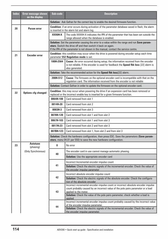
114 ADV200 • Quick start up guide - Specification and installation
Index Error message shown on the display
Sub-code Description
Solution: Ask Gefran for the correct key to enable the desired firmware function.
20 Param errorCondition: if an error occurs during activation of the parameter database saved in flash; the alarm is inserted in the alarm list and alarm log.
XXX0H-X The code XXXXH-X indicates the IPA of the parameter that has been set outside the range allowed when the database is enabled.
Solution: Set the parameter causing the error to a value within the range and run Save param-eters. Switch the drive off and then switch it back on again.If the IPA of the parameter is not shown in the manual, contact the service centre.
21 Encoder errorCondition: this condition may occur when the drive is powered during encoder setup each time parameter 552 Regulation mode is set.
100H-2564 Cause: An error occurred during setup; the information received from the encoder is not reliable. If the encoder is used for feedback the Speed fbk loss [22] alarm is also generated.
Solution: Take the recommended action for the Speed fbk loss[22] alarm.
200H-512 Cause: The firmware on the optional encoder card is incompatible with that on the regulation card. The information received from the encoder is not reliable
Solution: Contact Gefran in order to update the firmware on the optional encoder card.
22 Options cfg changedCondition: this may occur when powering the drive if an expansion card has been removed or replaced or the incorrect enable key is inserted for a given firmware function.
0064H-100 Card removed from slot 1
0014H-20 Card removed from slot 2
0003H-3 Card removed from slot 3
0078H-120 Card removed from slot 1 and from slot 2
0067H-103 Card removed from slot 1 and from slot 3
0017H-23 Card removed from slot 2 and from slot 3
007BH-123 Card removed from slot 1, from slot 2 and from slot 3
Solution: Check the hardware configuration, then press ESC. Save the parameters (Save param-eters, menu 04.01 par 550) to save the new hardware configuration.
23Autotune(phasing)
0 No error
(Only Synchronous)40
The encoder card in use cannot manage automatic phasing.
Solution: Use the appropriate encoder card
41Incorrect Incremental encoder impulse count
Solution: Check the electric signals of the incremental encoder. Check the value of the encoder impulse parameter
42Incorrect absolute encoder impulse count
Solution: Check the electric signals of the absolute encoder. Check the configura-tion of the absolute encoder
43
Incorrect incremental encoder impulse count or incorrect absolute encoder impulse count probably caused by an incorrect value of the pole pairs parameter or a load applied to the motor.Solution: Check the value of the pole pairs parameter, check whether a load is applied
44
Incorrect incremental encoder impulse count probably caused by the incorrect value of the encoder impulse parameter.Solution: Check the electric signals of the incremental encoder. Check the value of the encoder impulse parameter.
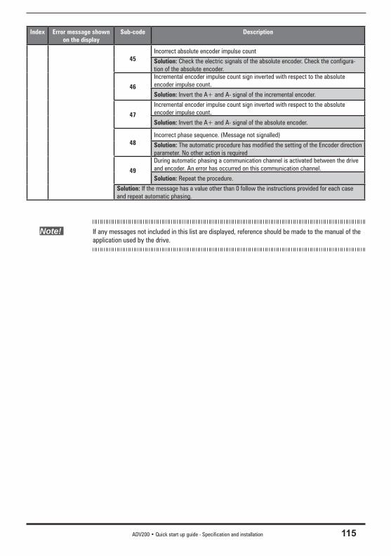
ADV200 • Quick start up guide - Specification and installation 115
Index Error message shown on the display
Sub-code Description
45Incorrect absolute encoder impulse count
Solution: Check the electric signals of the absolute encoder. Check the configura-tion of the absolute encoder.
46
Incremental encoder impulse count sign inverted with respect to the absolute encoder impulse count.
Solution: Invert the A+ and A- signal of the incremental encoder.
47
Incremental encoder impulse count sign inverted with respect to the absolute encoder impulse count.
Solution: Invert the A+ and A- signal of the absolute encoder.
48Incorrect phase sequence. (Message not signalled)
Solution: The automatic procedure has modified the setting of the Encoder direction parameter. No other action is required
49
During automatic phasing a communication channel is activated between the drive and encoder. An error has occurred on this communication channel.
Solution: Repeat the procedure.
Solution: If the message has a value other than 0 follow the instructions provided for each case and repeat automatic phasing.
Note! If any messages not included in this list are displayed, reference should be made to the manual of the application used by the drive.

116 ADV200 • Quick start up guide - Specification and installation
9 - Specifi cation
9.1 Environmental ConditionsInstallation location __________________Pollution degree 2 or lower (free from direct sunligth, vi-
bration, dust, corrosive or inflammable gases, fog, vapour oil and dripped water, avoid saline environment)
Installation altitude __________________Max 2000m (6562 feet) above sea level;. Mechanical conditions for installation ___Vibrational stress: EN 60721-3-3 Class 3M1Operating temperature ______________-10…+40°C (32°…104°F) Operating temperature (1) ____________+40 ... +50°C with derating, (+104 … +122°F with
derating)Air humidity (operating) ______________5 % to 85 % and 1 g/m3 to 25 g/m3 without moisture
condensation or icing (class 3K3 as per EN50178)Air pressure (operating) [kPa] __________86 to 106 (class 3K3 as per EN50178)
(1) In menu 4 - DRIVE CONFIG set the Ambient temperature parameter, PAR 564, to 1 (50°C).
10 % derating of output current.
The drive is suitable for use under the environmental service conditions (climate, mechanical, pollution, etc.) defi ned as usual service conditions according to EN61800-2.
9.2 StandardsClimatic conditions __________________EN 60721-3-3
Electrical safety ____________________EN 50178, EN 61800-5-1, UL508C, UL840 degree of pollution 2
Vibration __________________________EN 60068-2-6, test Fc.
EMC compatibility ___________________EN61800-3
Protection degree ___________________IP20, ≥ size 7: IP00
Approvals _________________________ , LL
9.3 Accuracy (Asyncronous)9.3.1 Current controlType ______________________________FOC CL (Field Oriented Control with feedback) and FOC
OL (open loop Field Oriented Control)Loop sampling time ___________________125μsResponse time ______________________600 - 1600μsPWM frequency _____________________2, 4, 6, 8, 10, 12 kHz (size dependent)
9.3.2 Speed controlType ______________________________FOC CL (Field Oriented Control with feedback) and FOC
OL (open loop Field Oriented Control)Loop sampling time ___________________125μsResponse time ______________________5 - 10msSpeed measurement __________________FP, F modeSpeed regulation accuracy _____________FOC with Speed feedback : 0.01 % rated speed FOC open loop : ± 30 % rated slip V/F : ± 60 % rated slip
Attention
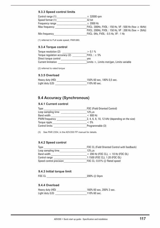
ADV200 • Quick start up guide - Specification and installation 117
9.3.3 Speed control limitsControl range (1) _____________________± 32000 rpmSpeed format (1) _____________________32 bitFrequency range _____________________± 2000 HzMax frequency ______________________FVCL: 300Hz, FVOL : 150 Hz, VF : 500 Hz (fsw ≥ 4kHz) FVCL: 200Hz, FVOL : 150 Hz, VF : 200 Hz (fsw = 2kHz)Min frequency _______________________FVCL: 0Hz, FVOL : 0.5 Hz, VF : 1 Hz
(1) referred to Full scale speed, PAR:680.
9.3.4 Torque controlTorque resolution (2) _________________> 0.1 % Torque regulation accuracy (2) __________FVCL : ± 5% Direct torque control __________________yesCurrent limitation ____________________Limits ±, Limits mot/gen, Limits variable
(2) referred to rated torque
9.3.5 OverloadHeavy duty (HD) _____________________150% 60 sec, 180% 0,5 sec.Light duty (LD) ______________________110% 60 sec.
9.4 Accuracy (Synchronous)9.4.1 Current controlType ______________________________FOC (Field Oriented Control)Loop sampling time __________________125 μsBand width _________________________< 800 HzPWM frequency _____________________2, 4, 6, 8, 10, 12 kHz (depending on the size)Torque ripple ________________________< 5%Control limits _______________________Programmable (3)
(3) See PAR 2354, in the ADV200 FP manual for details.
9.4.2 Speed controlType ______________________________FOC CL (Field Oriented Control with feedback)Loop sampling time ___________________125 μsBand width _________________________< 200 Hz (FOC CL), < 10 Hz (FOC OL)Control range _______________________1:1500 (FOC CL), 1:20 (FOC OL)Speed control precision ________________FOC CL: 0.01% @ Rated speed
9.4.3 Initial torque limitFOC CL ____________________________200% @ 0rpm
9.4.4 OverloadHeavy duty (HD) _____________________160% 60 sec, 200% 3 sec.Light duty (LD) ______________________110% 60 sec.
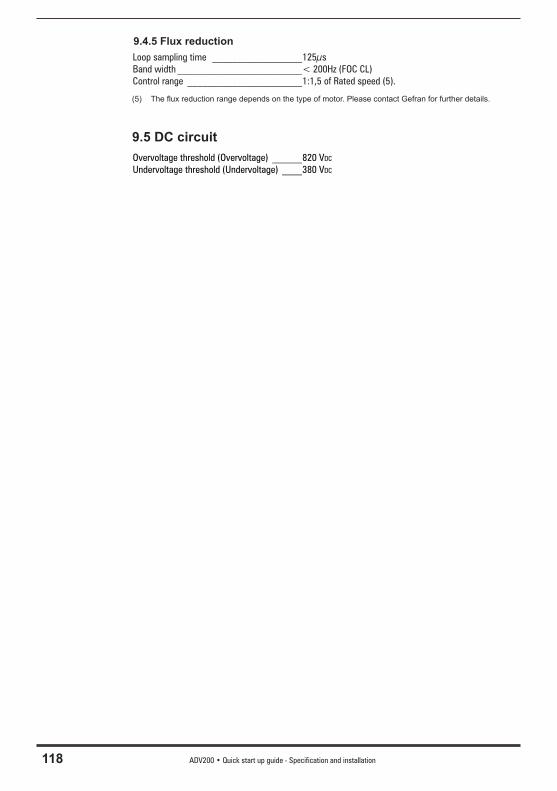
118 ADV200 • Quick start up guide - Specification and installation
9.4.5 Flux reductionLoop sampling time __________________125μsBand width _________________________< 200Hz (FOC CL)Control range _______________________1:1,5 of Rated speed (5).
(5) The fl ux reduction range depends on the type of motor. Please contact Gefran for further details.
9.5 DC circuitOvervoltage threshold (Overvoltage) ______820 VDC
Undervoltage threshold (Undervoltage) ____380 VDC
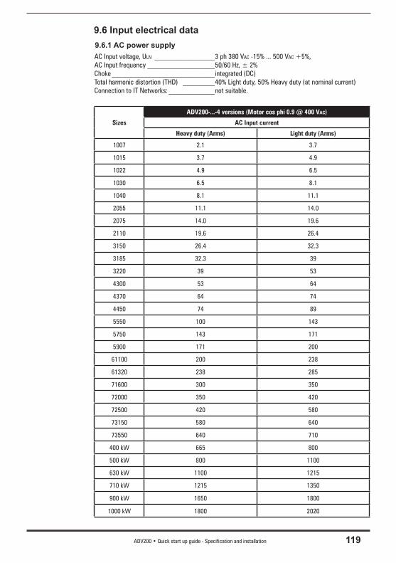
ADV200 • Quick start up guide - Specification and installation 119
9.6 Input electrical data9.6.1 AC power supplyAC Input voltage, ULN _________________3 ph 380 VAC -15% ... 500 VAC +5%, AC Input frequency ___________________50/60 Hz, ± 2%Choke _____________________________integrated (DC)Total harmonic distortion (THD) _________40% Light duty, 50% Heavy duty (at nominal current)Connection to IT Networks: _____________not suitable.
Sizes
ADV200-...-4 versions (Motor cos phi 0.9 @ 400 VAC)
AC Input current
Heavy duty (Arms) Light duty (Arms)
1007 2.1 3.7
1015 3.7 4.9
1022 4.9 6.5
1030 6.5 8.1
1040 8.1 11.1
2055 11.1 14.0
2075 14.0 19.6
2110 19.6 26.4
3150 26.4 32.3
3185 32.3 39
3220 39 53
4300 53 64
4370 64 74
4450 74 89
5550 100 143
5750 143 171
5900 171 200
61100 200 238
61320 238 285
71600 300 350
72000 350 420
72500 420 580
73150 580 640
73550 640 710
400 kW 665 800
500 kW 800 1100
630 kW 1100 1215
710 kW 1215 1350
900 kW 1650 1800
1000 kW 1800 2020
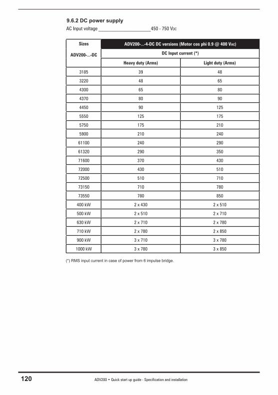
120 ADV200 • Quick start up guide - Specification and installation
9.6.2 DC power supplyAC Input voltage _____________________450 - 750 VDC
Sizes
ADV200-...-DC
ADV200-...-4-DC DC versions (Motor cos phi 0.9 @ 400 VAC)
DC Input current (*)
Heavy duty (Arms) Light duty (Arms)
3185 39 48
3220 48 65
4300 65 80
4370 80 90
4450 90 125
5550 125 175
5750 175 210
5900 210 240
61100 240 290
61320 290 350
71600 370 430
72000 430 510
72500 510 710
73150 710 780
73550 780 850
400 kW 2 x 430 2 x 510
500 kW 2 x 510 2 x 710
630 kW 2 x 710 2 x 780
710 kW 2 x 780 2 x 850
900 kW 3 x 710 3 x 780
1000 kW 3 x 780 3 x 850
(*) RMS input current in case of power from 6 impulse bridge.
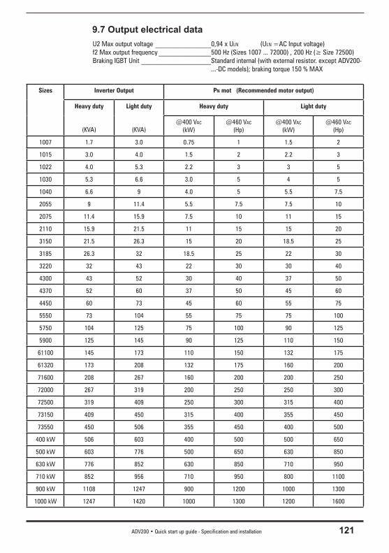
ADV200 • Quick start up guide - Specification and installation 121
9.7 Output electrical dataU2 Max output voltage ________________0,94 x ULN (ULN =AC Input voltage)f2 Max output frequency _______________500 Hz (Sizes 1007 ... 72000) , 200 Hz (≥ Size 72500) Braking IGBT Unit ____________________Standard internal (with external resistor. except ADV200-
...-DC models); braking torque 150 % MAX
Sizes Inverter Output PN mot (Recommended motor output)
Heavy duty
(KVA)
Light duty
(KVA)
Heavy duty Light duty
@400 VAC
(kW)@460 VAC
(Hp)@400 VAC
(kW)@460 VAC
(Hp)
1007 1.7 3.0 0.75 1 1.5 2
1015 3.0 4.0 1.5 2 2.2 3
1022 4.0 5.3 2.2 3 3 5
1030 5.3 6.6 3.0 5 4 5
1040 6.6 9 4.0 5 5.5 7.5
2055 9 11.4 5.5 7.5 7.5 10
2075 11.4 15.9 7.5 10 11 15
2110 15.9 21.5 11 15 15 20
3150 21.5 26.3 15 20 18.5 25
3185 26.3 32 18.5 25 22 30
3220 32 43 22 30 30 40
4300 43 52 30 40 37 50
4370 52 60 37 50 45 60
4450 60 73 45 60 55 75
5550 73 104 55 75 75 100
5750 104 125 75 100 90 125
5900 125 145 90 125 110 150
61100 145 173 110 150 132 175
61320 173 208 132 175 160 200
71600 208 267 160 200 200 250
72000 267 319 200 250 250 300
72500 319 409 250 300 315 400
73150 409 450 315 400 355 450
73550 450 506 355 450 400 500
400 kW 506 603 400 500 500 650
500 kW 603 776 500 650 630 850
630 kW 776 852 630 850 710 950
710 kW 852 956 710 950 800 1100
900 kW 1108 1247 900 1200 1000 1300
1000 kW 1247 1420 1000 1300 1200 1600
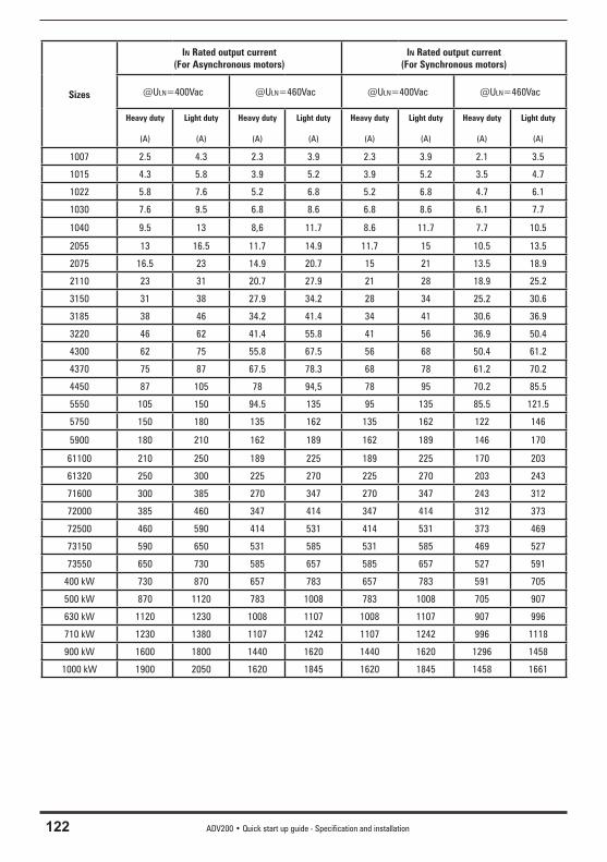
122 ADV200 • Quick start up guide - Specification and installation
Sizes
IN Rated output current (For Asynchronous motors)
IN Rated output current (For Synchronous motors)
@ULN=400Vac @ULN=460Vac @ULN=400Vac @ULN=460Vac
Heavy duty
(A)
Light duty
(A)
Heavy duty
(A)
Light duty
(A)
Heavy duty
(A)
Light duty
(A)
Heavy duty
(A)
Light duty
(A)
1007 2.5 4.3 2.3 3.9 2.3 3.9 2.1 3.5
1015 4.3 5.8 3.9 5.2 3.9 5.2 3.5 4.7
1022 5.8 7.6 5.2 6.8 5.2 6.8 4.7 6.1
1030 7.6 9.5 6.8 8.6 6.8 8.6 6.1 7.7
1040 9.5 13 8,6 11.7 8.6 11.7 7.7 10.5
2055 13 16.5 11.7 14.9 11.7 15 10.5 13.5
2075 16.5 23 14.9 20.7 15 21 13.5 18.9
2110 23 31 20.7 27.9 21 28 18.9 25.2
3150 31 38 27.9 34.2 28 34 25.2 30.6
3185 38 46 34.2 41.4 34 41 30.6 36.9
3220 46 62 41.4 55.8 41 56 36.9 50.4
4300 62 75 55.8 67.5 56 68 50.4 61.2
4370 75 87 67.5 78.3 68 78 61.2 70.2
4450 87 105 78 94,5 78 95 70.2 85.5
5550 105 150 94.5 135 95 135 85.5 121.5
5750 150 180 135 162 135 162 122 146
5900 180 210 162 189 162 189 146 170
61100 210 250 189 225 189 225 170 203
61320 250 300 225 270 225 270 203 243
71600 300 385 270 347 270 347 243 312
72000 385 460 347 414 347 414 312 373
72500 460 590 414 531 414 531 373 469
73150 590 650 531 585 531 585 469 527
73550 650 730 585 657 585 657 527 591
400 kW 730 870 657 783 657 783 591 705
500 kW 870 1120 783 1008 783 1008 705 907
630 kW 1120 1230 1008 1107 1008 1107 907 996
710 kW 1230 1380 1107 1242 1107 1242 996 1118
900 kW 1600 1800 1440 1620 1440 1620 1296 1458
1000 kW 1900 2050 1620 1845 1620 1845 1458 1661
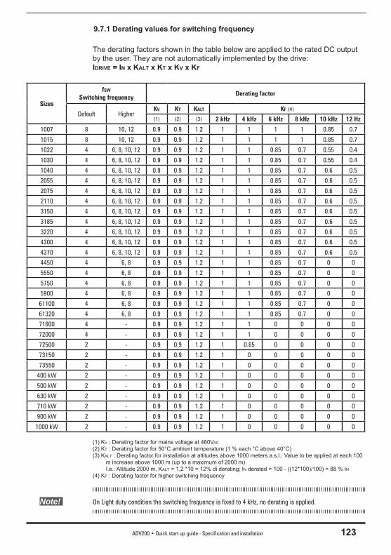
ADV200 • Quick start up guide - Specification and installation 123
9.7.1 Derating values for switching frequency
The derating factors shown in the table below are applied to the rated DC output by the user. They are not automatically implemented by the drive: IDRIVE = IN x KALT x KT x KV x KF
Sizes
fSW Switching frequency
Derating factor
Default HigherKV KT KALT KF (4)
(1) (2) (3) 2 kHz 4 kHz 6 kHz 8 kHz 10 kHz 12 Hz
1007 8 10, 12 0.9 0.9 1.2 1 1 1 1 0.85 0.7
1015 8 10, 12 0.9 0.9 1.2 1 1 1 1 0.85 0.7
1022 4 6, 8, 10, 12 0.9 0.9 1.2 1 1 0.85 0.7 0.55 0.4
1030 4 6, 8, 10, 12 0.9 0.9 1.2 1 1 0.85 0.7 0.55 0.4
1040 4 6, 8, 10, 12 0.9 0.9 1.2 1 1 0.85 0.7 0.6 0.5
2055 4 6, 8, 10, 12 0.9 0.9 1.2 1 1 0.85 0.7 0.6 0.5
2075 4 6, 8, 10, 12 0.9 0.9 1.2 1 1 0.85 0.7 0.6 0.5
2110 4 6, 8, 10, 12 0.9 0.9 1.2 1 1 0.85 0.7 0.6 0.5
3150 4 6, 8, 10, 12 0.9 0.9 1.2 1 1 0.85 0.7 0.6 0.5
3185 4 6, 8, 10, 12 0.9 0.9 1.2 1 1 0.85 0.7 0.6 0.5
3220 4 6, 8, 10, 12 0.9 0.9 1.2 1 1 0.85 0.7 0.6 0.5
4300 4 6, 8, 10, 12 0.9 0.9 1.2 1 1 0.85 0.7 0.6 0.5
4370 4 6, 8, 10, 12 0.9 0.9 1.2 1 1 0.85 0.7 0.6 0.5
4450 4 6, 8 0.9 0.9 1.2 1 1 0.85 0.7 0 0
5550 4 6, 8 0.9 0.9 1.2 1 1 0.85 0.7 0 0
5750 4 6, 8 0.9 0.9 1.2 1 1 0.85 0.7 0 0
5900 4 6, 8 0.9 0.9 1.2 1 1 0.85 0.7 0 0
61100 4 6, 8 0.9 0.9 1.2 1 1 0.85 0.7 0 0
61320 4 6, 8 0.9 0.9 1.2 1 1 0.85 0.7 0 0
71600 4 - 0.9 0.9 1.2 1 1 0 0 0 0
72000 4 - 0.9 0.9 1.2 1 1 0 0 0 0
72500 2 - 0.9 0.9 1.2 1 0.85 0 0 0 0
73150 2 - 0.9 0.9 1.2 1 0 0 0 0 0
73550 2 - 0.9 0.9 1.2 1 0 0 0 0 0
400 kW 2 - 0.9 0.9 1.2 1 0 0 0 0 0
500 kW 2 - 0.9 0.9 1.2 1 0 0 0 0 0
630 kW 2 - 0.9 0.9 1.2 1 0 0 0 0 0
710 kW 2 - 0.9 0.9 1.2 1 0 0 0 0 0
900 kW 2 - 0.9 0.9 1.2 1 0 0 0 0 0
1000 kW 2 - 0.9 0.9 1.2 1 0 0 0 0 0
(1) KV : Derating factor for mains voltage at 460VAC
(2) KT : Derating factor for 50°C ambient temperature (1 % each °C above 40°C)(3) KALT : Derating factor for installation at altitudes above 1000 meters a.s.l.. Value to be applied at each 100
m increase above 1000 m (up to a maximum of 2000 m). I.e.: Altitude 2000 m, KALT = 1,2 *10 = 12% di derating; IN derated = 100 - ((12*100)/100) = 88 % IN(4) KF : Derating factor for higher switching frequency
Note! On Light duty condition the switching frequency is fixed to 4 kHz, no derating is applied.
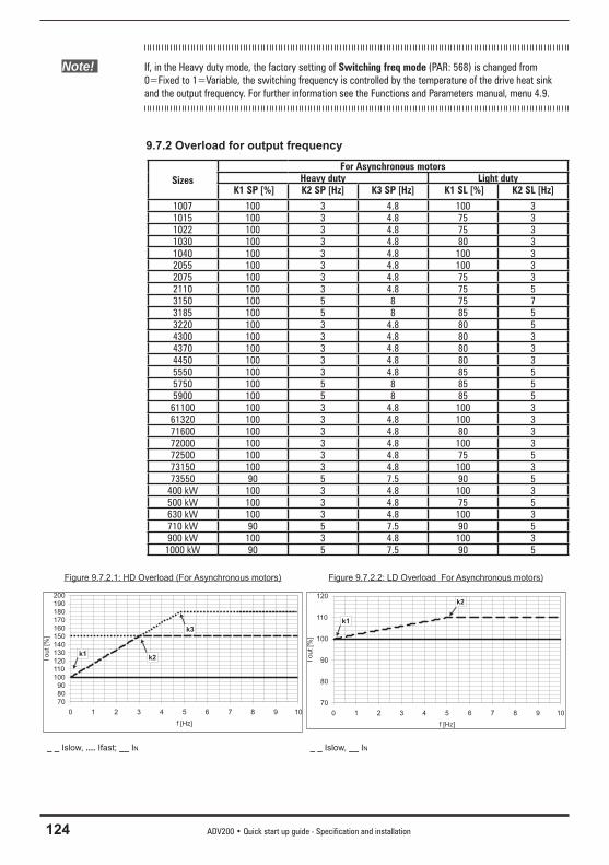
124 ADV200 • Quick start up guide - Specification and installation
Note! If, in the Heavy duty mode, the factory setting of Switching freq mode (PAR: 568) is changed from 0=Fixed to 1=Variable, the switching frequency is controlled by the temperature of the drive heat sink and the output frequency. For further information see the Functions and Parameters manual, menu 4.9.
9.7.2 Overload for output frequency
SizesFor Asynchronous motors
Heavy duty Light duty K1 SP [%] K2 SP [Hz] K3 SP [Hz] K1 SL [%] K2 SL [Hz]
1007 100 3 4.8 100 31015 100 3 4.8 75 31022 100 3 4.8 75 31030 100 3 4.8 80 31040 100 3 4.8 100 32055 100 3 4.8 100 32075 100 3 4.8 75 32110 100 3 4.8 75 53150 100 5 8 75 73185 100 5 8 85 53220 100 3 4.8 80 54300 100 3 4.8 80 34370 100 3 4.8 80 34450 100 3 4.8 80 35550 100 3 4.8 85 55750 100 5 8 85 55900 100 5 8 85 561100 100 3 4.8 100 361320 100 3 4.8 100 371600 100 3 4.8 80 372000 100 3 4.8 100 372500 100 3 4.8 75 573150 100 3 4.8 100 373550 90 5 7.5 90 5
400 kW 100 3 4.8 100 3500 kW 100 3 4.8 75 5630 kW 100 3 4.8 100 3710 kW 90 5 7.5 90 5900 kW 100 3 4.8 100 31000 kW 90 5 7.5 90 5
Figure 9.7.2.1: HD Overload (For Asynchronous motors) Figure 9.7.2.2: LD Overload For Asynchronous motors)
708090
100110120130140150160170180190200
0 1 2 3 4 5 6 7 8 9 10
f [Hz]
Iout
[%]
k1k2
k3
70
80
90
100
110
120
0 1 2 3 4 5 6 7 8 9 10
f [Hz]
Iout[%
]
k1
k2
_ _ Islow, .... Ifast; __ IN _ _ Islow, __ IN
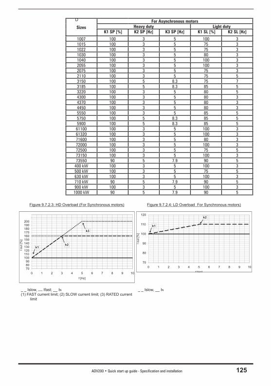
ADV200 • Quick start up guide - Specification and installation 125
D
SizesFor Asynchronous motors
Heavy duty Light duty K1 SP [%] K2 SP [Hz] K3 SP [Hz] K1 SL [%] K2 SL [Hz]
1007 100 3 5 100 31015 100 3 5 75 31022 100 3 5 75 31030 100 3 5 80 31040 100 3 5 100 32055 100 3 5 100 32075 100 3 5 75 32110 100 3 5 75 53150 100 5 8.3 75 73185 100 5 8.3 85 53220 100 3 5 80 54300 100 3 5 80 34370 100 3 5 80 34450 100 3 5 80 35550 100 3 5 85 55750 100 5 8.3 85 55900 100 5 8.3 85 561100 100 3 5 100 361320 100 3 5 100 371600 100 3 5 80 372000 100 3 5 100 372500 100 3 5 75 573150 100 3 5 100 373550 90 5 7.9 90 5
400 kW 100 3 5 100 3500 kW 100 3 5 75 5630 kW 100 3 5 100 3710 kW 90 5 7.9 90 5900 kW 100 3 5 100 31000 kW 90 5 7.9 90 5
Figure 9.7.2.3: HD Overload (For Synchronous motors) Figure 9.7.2.4: LD Overload For Synchronous motors)
708090
100110120130140150160170180190200
0 1 2 3 4 5 6 7 8 9 10
f [Hz]
Iout
[%]
k1k2
k3
70
80
90
100
110
120
0 1 2 3 4 5 6 7 8 9 10
f [Hz]
Iout[%
]
k1
k2
_ _ Islow, .... Ifast; __ IN(1) FAST current limit; (2) SLOW current limit; (3) RATED current
limit
_ _ Islow, __ IN

126 ADV200 • Quick start up guide - Specification and installation
9.8 Voltage level of the inverter for safe operationsThe minimum time between the moment in which an ADV200 drive is disabled from the mains and that in which an operator can operate on internal parts of the drive, without the danger of electric shock, is 5 minutes.
The value consider the time to turn-off for a drive supplied at 460VAC +10%, without any options (time indicated for disabled drive condition).
Attention
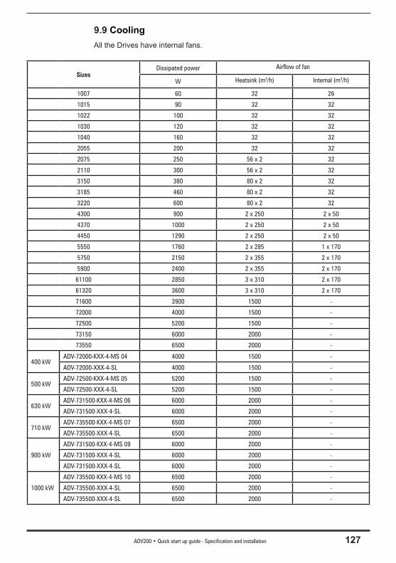
ADV200 • Quick start up guide - Specification and installation 127
9.9 CoolingAll the Drives have internal fans.
SizesDissipated power Airflow of fan
W Heatsink (m3/h) Internal (m3/h)
1007 60 32 26
1015 90 32 32
1022 100 32 32
1030 120 32 32
1040 160 32 32
2055 200 32 32
2075 250 56 x 2 32
2110 300 56 x 2 32
3150 380 80 x 2 32
3185 460 80 x 2 32
3220 600 80 x 2 32
4300 900 2 x 250 2 x 50
4370 1000 2 x 250 2 x 50
4450 1290 2 x 250 2 x 50
5550 1760 2 x 285 1 x 170
5750 2150 2 x 355 2 x 170
5900 2400 2 x 355 2 x 170
61100 2850 3 x 310 2 x 170
61320 3600 3 x 310 2 x 170
71600 3900 1500 -
72000 4000 1500 -
72500 5200 1500 -
73150 6000 2000 -
73550 6500 2000 -
400 kWADV-72000-KXX-4-MS 04 4000 1500 -
ADV-72000-XXX-4-SL 4000 1500 -
500 kWADV-72500-KXX-4-MS 05 5200 1500 -
ADV-72500-XXX-4-SL 5200 1500 -
630 kWADV-731500-KXX-4-MS 06 6000 2000 -
ADV-731500-XXX-4-SL 6000 2000 -
710 kWADV-735500-KXX-4-MS 07 6500 2000 -
ADV-735500-XXX-4-SL 6500 2000 -
900 kW
ADV-731500-KXX-4-MS 09 6000 2000 -
ADV-731500-XXX-4-SL 6000 2000 -
ADV-731500-XXX-4-SL 6000 2000 -
1000 kW
ADV-735500-KXX-4-MS 10 6500 2000 -
ADV-735500-XXX-4-SL 6500 2000 -
ADV-735500-XXX-4-SL 6500 2000 -
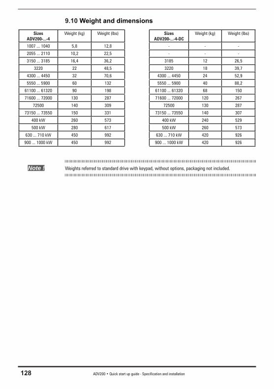
128 ADV200 • Quick start up guide - Specification and installation
9.10 Weight and dimensions
SizesADV200-...-4
Weight (kg) Weight (lbs) SizesADV200-...-4-DC
Weight (kg) Weight (lbs)
1007 ... 1040 5,8 12,8 - - -
2055 ... 2110 10,2 22,5 - - -
3150 ... 3185 16,4 36,2 3185 12 26,5
3220 22 48,5 3220 18 39,7
4300 ... 4450 32 70,6 4300 ... 4450 24 52,9
5550 ... 5900 60 132 5550 ... 5900 40 88,2
61100 ... 61320 90 198 61100 ... 61320 68 150
71600 ... 72000 130 287 71600 ... 72000 120 267
72500 140 309 72500 130 287
73150 ... 73550 150 331 73150 ... 73550 140 307
400 kW 260 573 400 kW 240 529
500 kW 280 617 500 kW 260 573
630 ... 710 kW 450 992 630 ... 710 kW 420 926
900 ... 1000 kW 450 992 900 ... 1000 kW 420 926
Note ! Weights referred to standard drive with keypad, without options, packaging not included.
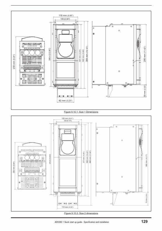
ADV200 • Quick start up guide - Specification and installation 129
118 mm (4.65”)
82 mm (3.23”)
290
mm
(11
.42
”)
235
mm
(9.2
5”)
59
mm
(2.3
2”)
307
mm
(12
.09
”)
384
mm
(15
.12
”)
322
mm
(12
.68
”)
100 [3.94”]
30
6.4
[12
.06
”]
Figure 9.10.1: Size 1 Dimensions
150 mm (5.91”)
110 mm (4.33”)
360
mm
(14
.17
”)
250
mm
(9.8
4”)
70
mm
(2.7
6”)
377
mm
(14
.84
”)
392
mm
(15
.43
”)
440
mm
(17
.32
”)
120 [4.72”]
376.6
[14.8
3”]
Figure 9.10.2: Size 2 dimensions
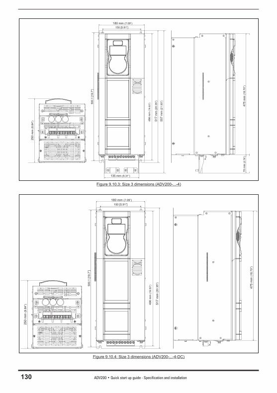
130 ADV200 • Quick start up guide - Specification and installation
180 mm (7.09”)
135 mm (5.31”)
47
5m
m(1
8.7
0”)
70
mm
(2.7
6”)
25
0m
m(8
.84”) 4
96
mm
(19.5
3”)
51
7m
m(2
0.3
5”)
55
7m
m(2
1.9
3”)
150 [5.91”]
500.1
[19.7
”]
Figure 9.10.3: Size 3 dimensions (ADV200-...-4)
180 mm (7.09”)
475
mm
(18.7
0”)
250
mm
(8.8
4”) 4
96
mm
(19.5
3”)
517
mm
(20.3
5”)
150 [5.91”]
50
0.1
[19.7
”]
Figure 9.10.4: Size 3 dimensions (ADV200-...-4-DC)

ADV200 • Quick start up guide - Specification and installation 131
268 [10.55”]
682
[26.8
5”]
270
[10.6
3”]
682
[26.8
5”]
616
[24.2
5”]
612
[24.0
9”]
Figure 9.10.5: Size 4 dimensions (ADV200-...-4)
268 [10.55”]
270
[10.6
3”]
616
[24.2
5”]
612
[24.0
9”]
Figure 9.10.6: Size 4 dimensions (ADV200-...-4-DC)
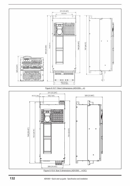
132 ADV200 • Quick start up guide - Specification and installation
311 [12.24”]
74
8[2
9.4
5”]
85
3[3
3.5
8”]
76
7[4
0.2
”]
32
5[1
2.8
”]
730
[28.7
4”]
220 [8.66”]
279 [10.98”]265 [10.43”]
Figure 9.10.7: Size 5 dimensions (ADV200-...-4)
311 [12.24”]
190 [7.48”]
730.4
[28.7
6”]
74
8[2
9.4
5”]
265 [10.43”]
730.4
[30.5
5”]
325 [12.80”]45.5 [1.79”]
Figure 9.10.8: Size 5 dimensions (ADV200-...-4-DC)
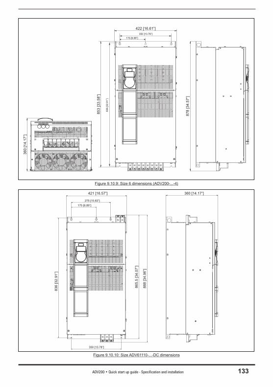
ADV200 • Quick start up guide - Specification and installation 133
422 [16.61”]
853
[33.5
8”]
878
[34.5
7”]
360
[14.1
7”]
350 [13.78”]
175 [6.89”]
836
[32.9
1”]
Figure 9.10.9: Size 6 dimensions (ADV200-...-4)
421 [16.57”]
350 [13.78”]
175 [6.89”]
83
6[3
2.9
1”]
275 [10.83”]
88
8[3
4.9
6”]
86
5.5
[34
.07
”]
360 [14.17”]
Figure 9.10.10: Size ADV61110-...-DC dimensions
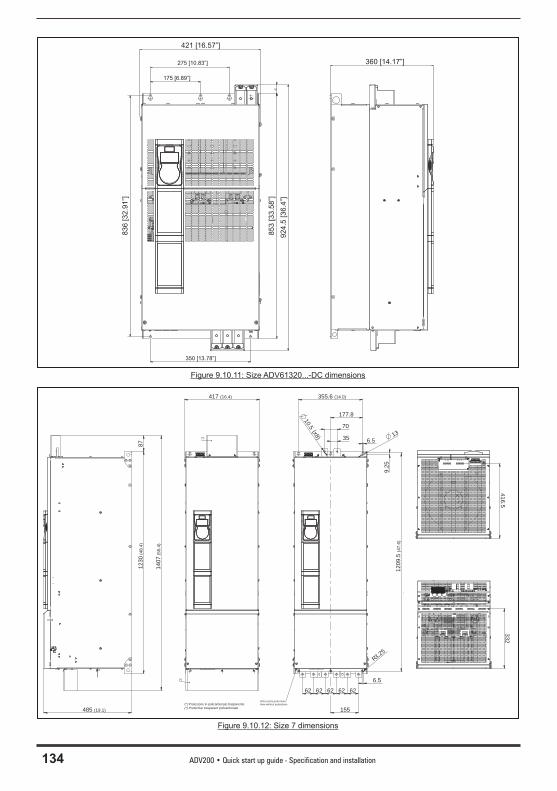
134 ADV200 • Quick start up guide - Specification and installation
421 [16.57”]
350 [13.78”]
175 [6.89”]
83
6[3
2.9
1”]
275 [10.83”] 360 [14.17”]
85
3[3
3.5
8”]
924
.5[3
6.4
”]
Figure 9.10.11: Size ADV61320...-DC dimensions
417 (16.4)
1230
(48.
4)
1407
(55.
4)
485 (19.1)
1209
.5 (4
7.6)
355.6 (14.0)
177.8
155
6262626262
35
70 (x8)
10.5
6.513
9.25
6.5
R3.25
332416.5
87
Vista senza protezioniView without protections
(*)
(*)
(*) Protezione in policarbonato trasparente(*) Protective trasparent policarbonate
Figure 9.10.12: Size 7 dimensions
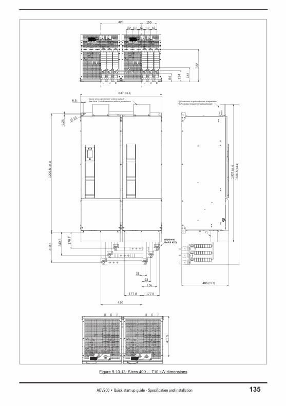
ADV200 • Quick start up guide - Specification and installation 135
485 [19.1]
1209
.5 [4
7.6]
170.
7
240.
5
310.
5
177.8177.8
420
31
93
155
837 [33.0]
1407
[55.
4]
1636
.5 [6
4.4]
9.25
13
6.5
332
416.
5
(*)
(*) Protezione in policarbonato trasparente(*) Protective trasparent policarbonate
(Optional BARS KIT)
144
114
84
420 155
6262 626262
Quote senza protezioni vedere taglia 7 See Size 7 for dimensions without protections.
Figure 9.10.13: Sizes 400 ... 710 kW dimensions
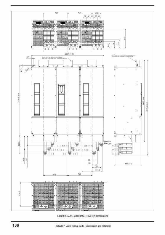
136 ADV200 • Quick start up guide - Specification and installation
6.5
1257 [49.49]
9.25 13
1209
.5 [4
7.6]
310.
5
240.
517
0.7
420 420
3193
155
177.8
(Optional BARS KIT)
(*)
485 [19.1]
1636
.5 [6
4.4]
1407
[55.
4]
416,
5
Quote senza protezioni vedere taglia 7 See Size 7 for dimensions without protections.
(*) Protezione in policarbonato trasparente(*) Protective trasparent policarbonate
332
144
114
84
420 155
6262 626262
420
Figure 9.10.14: Sizes 900 - 1000 kW dimensions
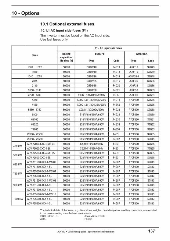
ADV200 • Quick start up guide - Specification and installation 137
10 - Options
10.1 Optional external fuses 10.1.1 AC input side fuses (F1)The inverter must be fused on the AC Input side. Use fast fuses only.
Sizes
F1 - AC input side fuses
DC link capacitors life time [h]
EUROPE AMERICA
Type Code Type Code
1007 ... 1022 50000 GRD2/10 F4D13 A70P10 S7G49
1030 50000 GRD2/10 F4D13 A70P10 S7G49
1040 ... 2055 50000 GRD2/16 F4D14 A70P20-1 S7G48
2075 50000 GRD2/25 F4D16 A70P35 S7G86
2110 50000 GRD3/35 F4D20 A70P35 S7G86
3150 - 3185 50000 GRD3/50 F4D21 A70P50 S7G53
3220 - 4300 50000 S00C+/üf1/80/80A/690V F4EAF A70P80 S7G54
4370 50000 S00C+/üf1/80/100A/690V F4G18 A70P100 S7G55
4450 50000 S00C+/üf1/80/125A/690V F4EAJ A70P150 S7G56
5550 - 5750 50000 S00/üf1/80/200A/690V F4G23 A70P200 S7G58
5900 50000 S1üf1/110/250A/690V F4G28 A70P250 S7G59
61100 50000 S1üf1/110/315A/690V F4G30 A70P350 S7G61
61320 50000 S2üf1/110/400A/690V F4G34 A70P400 S7G62
71600 50000 S2üf1/110/500A/690V F4E30 A70P500 S7G63
72000 - 72500 50000 S2üf1/110/630A/690V F4E31 A70P600 S7G65
73150 - 73550 50000 S2üf1/110/800A/690V F4G87 A70P800 S7813
400 kWADV-72000-KXX-4-MS 04 50000 S2üf1/110/630A/690V F4E31 A70P600 S7G65
ADV-72000-XXX-4-SL 50000 S2üf1/110/630A/690V F4E31 A70P600 S7G65
500 kWADV-72500-KXX-4-MS 05 50000 S2üf1/110/630A/690V F4E31 A70P600 S7G65
ADV-72500-XXX-4-SL 50000 S2üf1/110/630A/690V F4E31 A70P600 S7G65
630 kWADV-731500-KXX-4-MS 06 50000 S2üf1/110/800A/690V F4G87 A70P800 S7813
ADV-731500-XXX-4-SL 50000 S2üf1/110/800A/690V F4G87 A70P800 S7813
710 kWADV-735500-KXX-4-MS 07 50000 S2üf1/110/800A/690V F4G87 A70P800 S7813
ADV-735500-XXX-4-SL 50000 S2üf1/110/800A/690V F4G87 A70P800 S7813
900 kW
ADV-731500-KXX-4-MS 09 50000 S2üf1/110/800A/690V F4G87 A70P800 S7813
ADV-731500-XXX-4-SL 50000 S2üf1/110/800A/690V F4G87 A70P800 S7813
ADV-731500-XXX-4-SL 50000 S2üf1/110/800A/690V F4G87 A70P800 S7813
1000 kW
ADV-735500-KXX-4-MS 10 50000 S2üf1/110/800A/690V F4G87 A70P800 S7813
ADV-735500-XXX-4-SL 50000 S2üf1/110/800A/690V F4G87 A70P800 S7813
ADV-735500-XXX-4-SL 50000 S2üf1/110/800A/690V F4G87 A70P800 S7813
The technical data of the fuses, e.g. dimensions, weights, heat dissipation, auxiliary contactors, are reported in the corresponding manufacturer data sheets.GRD... (E27), S... Jean Müller, EltvilleA70... Ferraz
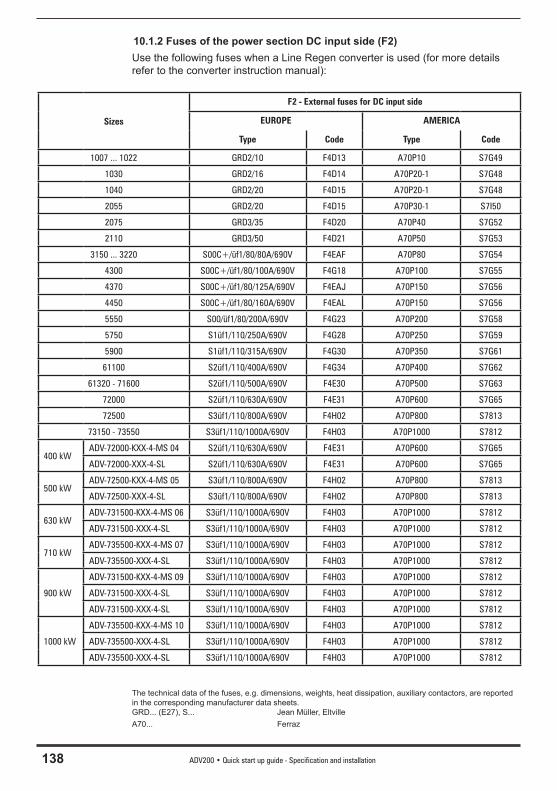
138 ADV200 • Quick start up guide - Specification and installation
10.1.2 Fuses of the power section DC input side (F2)Use the following fuses when a Line Regen converter is used (for more details refer to the converter instruction manual):
Sizes
F2 - External fuses for DC input side
EUROPE AMERICA
Type Code Type Code
1007 ... 1022 GRD2/10 F4D13 A70P10 S7G49
1030 GRD2/16 F4D14 A70P20-1 S7G48
1040 GRD2/20 F4D15 A70P20-1 S7G48
2055 GRD2/20 F4D15 A70P30-1 S7I50
2075 GRD3/35 F4D20 A70P40 S7G52
2110 GRD3/50 F4D21 A70P50 S7G53
3150 ... 3220 S00C+/üf1/80/80A/690V F4EAF A70P80 S7G54
4300 S00C+/üf1/80/100A/690V F4G18 A70P100 S7G55
4370 S00C+/üf1/80/125A/690V F4EAJ A70P150 S7G56
4450 S00C+/üf1/80/160A/690V F4EAL A70P150 S7G56
5550 S00/üf1/80/200A/690V F4G23 A70P200 S7G58
5750 S1üf1/110/250A/690V F4G28 A70P250 S7G59
5900 S1üf1/110/315A/690V F4G30 A70P350 S7G61
61100 S2üf1/110/400A/690V F4G34 A70P400 S7G62
61320 - 71600 S2üf1/110/500A/690V F4E30 A70P500 S7G63
72000 S2üf1/110/630A/690V F4E31 A70P600 S7G65
72500 S3üf1/110/800A/690V F4H02 A70P800 S7813
73150 - 73550 S3üf1/110/1000A/690V F4H03 A70P1000 S7812
400 kWADV-72000-KXX-4-MS 04 S2üf1/110/630A/690V F4E31 A70P600 S7G65
ADV-72000-XXX-4-SL S2üf1/110/630A/690V F4E31 A70P600 S7G65
500 kWADV-72500-KXX-4-MS 05 S3üf1/110/800A/690V F4H02 A70P800 S7813
ADV-72500-XXX-4-SL S3üf1/110/800A/690V F4H02 A70P800 S7813
630 kWADV-731500-KXX-4-MS 06 S3üf1/110/1000A/690V F4H03 A70P1000 S7812
ADV-731500-XXX-4-SL S3üf1/110/1000A/690V F4H03 A70P1000 S7812
710 kWADV-735500-KXX-4-MS 07 S3üf1/110/1000A/690V F4H03 A70P1000 S7812
ADV-735500-XXX-4-SL S3üf1/110/1000A/690V F4H03 A70P1000 S7812
900 kW
ADV-731500-KXX-4-MS 09 S3üf1/110/1000A/690V F4H03 A70P1000 S7812
ADV-731500-XXX-4-SL S3üf1/110/1000A/690V F4H03 A70P1000 S7812
ADV-731500-XXX-4-SL S3üf1/110/1000A/690V F4H03 A70P1000 S7812
1000 kW
ADV-735500-KXX-4-MS 10 S3üf1/110/1000A/690V F4H03 A70P1000 S7812
ADV-735500-XXX-4-SL S3üf1/110/1000A/690V F4H03 A70P1000 S7812
ADV-735500-XXX-4-SL S3üf1/110/1000A/690V F4H03 A70P1000 S7812
The technical data of the fuses, e.g. dimensions, weights, heat dissipation, auxiliary contactors, are reported in the corresponding manufacturer data sheets.GRD... (E27), S... Jean Müller, EltvilleA70... Ferraz
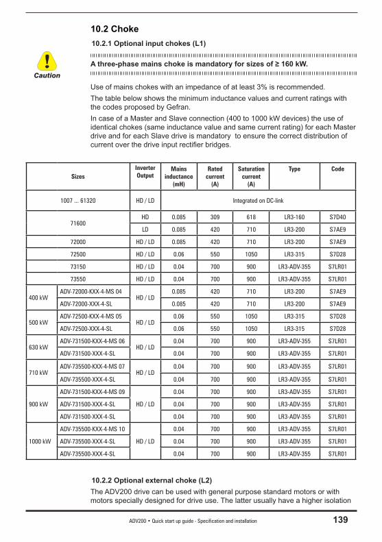
ADV200 • Quick start up guide - Specification and installation 139
10.2 Choke 10.2.1 Optional input chokes (L1)
A three-phase mains choke is mandatory for sizes of ≥ 160 kW.
Use of mains chokes with an impedance of at least 3% is recommended. The table below shows the minimum inductance values and current ratings with the codes proposed by Gefran. In case of a Master and Slave connection (400 to 1000 kW devices) the use of identical chokes (same inductance value and same current rating) for each Master drive and for each Slave drive is mandatory to ensure the correct distribution of current over the drive input rectifi er bridges.
SizesInverter Output
Mains inductance
(mH)
Rated current
(A)
Saturation current
(A)
Type Code
1007 ... 61320 HD / LD Integrated on DC-link
71600HD 0.085 309 618 LR3-160 S7D40
LD 0.085 420 710 LR3-200 S7AE9
72000 HD / LD 0.085 420 710 LR3-200 S7AE9
72500 HD / LD 0.06 550 1050 LR3-315 S7D28
73150 HD / LD 0.04 700 900 LR3-ADV-355 S7LR01
73550 HD / LD 0.04 700 900 LR3-ADV-355 S7LR01
400 kWADV-72000-KXX-4-MS 04
HD / LD0.085 420 710 LR3-200 S7AE9
ADV-72000-XXX-4-SL 0.085 420 710 LR3-200 S7AE9
500 kWADV-72500-KXX-4-MS 05
HD / LD0.06 550 1050 LR3-315 S7D28
ADV-72500-XXX-4-SL 0.06 550 1050 LR3-315 S7D28
630 kWADV-731500-KXX-4-MS 06
HD / LD0.04 700 900 LR3-ADV-355 S7LR01
ADV-731500-XXX-4-SL 0.04 700 900 LR3-ADV-355 S7LR01
710 kWADV-735500-KXX-4-MS 07
HD / LD0.04 700 900 LR3-ADV-355 S7LR01
ADV-735500-XXX-4-SL 0.04 700 900 LR3-ADV-355 S7LR01
900 kW
ADV-731500-KXX-4-MS 09
HD / LD
0.04 700 900 LR3-ADV-355 S7LR01
ADV-731500-XXX-4-SL 0.04 700 900 LR3-ADV-355 S7LR01
ADV-731500-XXX-4-SL 0.04 700 900 LR3-ADV-355 S7LR01
1000 kW
ADV-735500-KXX-4-MS 10
HD / LD
0.04 700 900 LR3-ADV-355 S7LR01
ADV-735500-XXX-4-SL 0.04 700 900 LR3-ADV-355 S7LR01
ADV-735500-XXX-4-SL 0.04 700 900 LR3-ADV-355 S7LR01
10.2.2 Optional external choke (L2)The ADV200 drive can be used with general purpose standard motors or with motors specially designed for drive use. The latter usually have a higher isolation
Caution
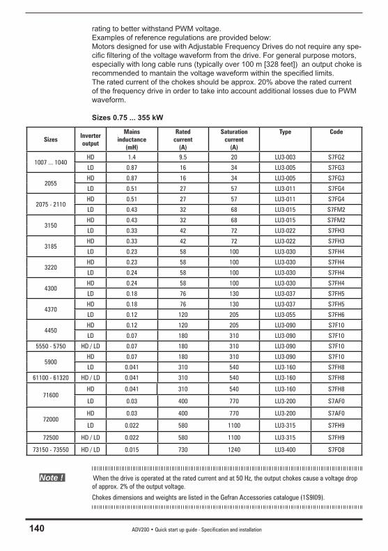
140 ADV200 • Quick start up guide - Specification and installation
rating to better withstand PWM voltage.Examples of reference regulations are provided below:Motors designed for use with Adjustable Frequency Drives do not require any spe-cifi c fi ltering of the voltage waveform from the drive. For general purpose motors, especially with long cable runs (typically over 100 m [328 feet]) an output choke is recommended to mantain the voltage waveform within the specifi ed limits. The rated current of the chokes should be approx. 20% above the rated current of the frequency drive in order to take into account additional losses due to PWM waveform.
Sizes 0.75 ... 355 kW
SizesInverter output
Mains inductance
(mH)
Rated current
(A)
Saturation current
(A)
Type Code
1007 ... 1040HD 1.4 9.5 20 LU3-003 S7FG2
LD 0.87 16 34 LU3-005 S7FG3
2055HD 0.87 16 34 LU3-005 S7FG3
LD 0.51 27 57 LU3-011 S7FG4
2075 - 2110HD 0.51 27 57 LU3-011 S7FG4
LD 0.43 32 68 LU3-015 S7FM2
3150HD 0.43 32 68 LU3-015 S7FM2
LD 0.33 42 72 LU3-022 S7FH3
3185HD 0.33 42 72 LU3-022 S7FH3
LD 0.23 58 100 LU3-030 S7FH4
3220HD 0.23 58 100 LU3-030 S7FH4
LD 0.24 58 100 LU3-030 S7FH4
4300HD 0.24 58 100 LU3-030 S7FH4
LD 0.18 76 130 LU3-037 S7FH5
4370HD 0.18 76 130 LU3-037 S7FH5
LD 0.12 120 205 LU3-055 S7FH6
4450HD 0.12 120 205 LU3-090 S7F10
LD 0.07 180 310 LU3-090 S7F10
5550 - 5750 HD / LD 0.07 180 310 LU3-090 S7F10
5900HD 0.07 180 310 LU3-090 S7F10
LD 0.041 310 540 LU3-160 S7FH8
61100 - 61320 HD / LD 0.041 310 540 LU3-160 S7FH8
71600HD 0.041 310 540 LU3-160 S7FH8
LD 0.03 400 770 LU3-200 S7AF0
72000HD 0.03 400 770 LU3-200 S7AF0
LD 0.022 580 1100 LU3-315 S7FH9
72500 HD / LD 0.022 580 1100 LU3-315 S7FH9
73150 - 73550 HD / LD 0.015 730 1240 LU3-400 S7FO8
Note ! When the drive is operated at the rated current and at 50 Hz, the output chokes cause a voltage drop of approx. 2% of the output voltage.
Chokes dimensions and weights are listed in the Gefran Accessories catalogue (1S9I09).
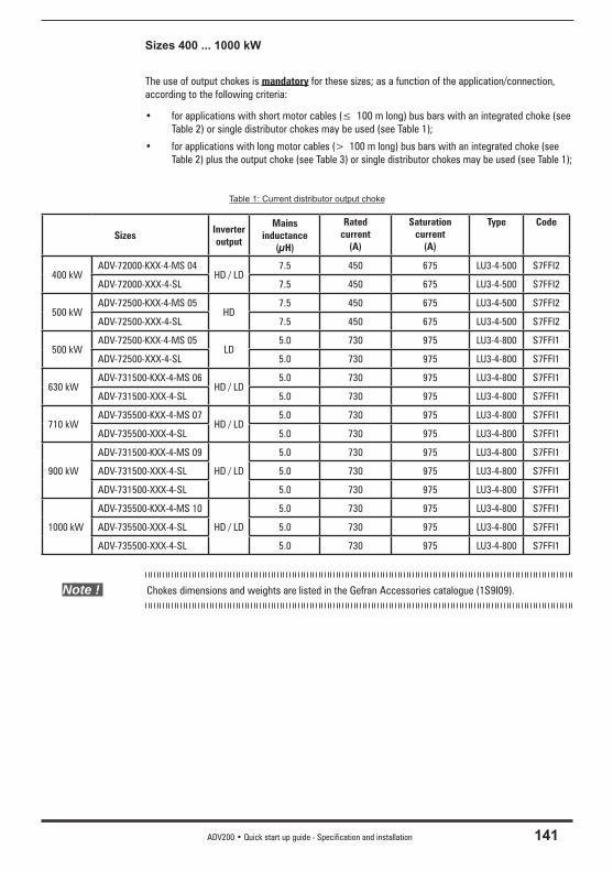
ADV200 • Quick start up guide - Specification and installation 141
Sizes 400 ... 1000 kW
The use of output chokes is mandatory for these sizes; as a function of the application/connection, according to the following criteria:
• for applications with short motor cables (≤ 100 m long) bus bars with an integrated choke (see Table 2) or single distributor chokes may be used (see Table 1);
• for applications with long motor cables (> 100 m long) bus bars with an integrated choke (see Table 2) plus the output choke (see Table 3) or single distributor chokes may be used (see Table 1);
Table 1: Current distributor output choke
SizesInverter output
Mains inductance
(μH)
Rated current
(A)
Saturation current
(A)
Type Code
400 kWADV-72000-KXX-4-MS 04
HD / LD7.5 450 675 LU3-4-500 S7FFI2
ADV-72000-XXX-4-SL 7.5 450 675 LU3-4-500 S7FFI2
500 kWADV-72500-KXX-4-MS 05
HD7.5 450 675 LU3-4-500 S7FFI2
ADV-72500-XXX-4-SL 7.5 450 675 LU3-4-500 S7FFI2
500 kWADV-72500-KXX-4-MS 05
LD5.0 730 975 LU3-4-800 S7FFI1
ADV-72500-XXX-4-SL 5.0 730 975 LU3-4-800 S7FFI1
630 kWADV-731500-KXX-4-MS 06
HD / LD5.0 730 975 LU3-4-800 S7FFI1
ADV-731500-XXX-4-SL 5.0 730 975 LU3-4-800 S7FFI1
710 kWADV-735500-KXX-4-MS 07
HD / LD5.0 730 975 LU3-4-800 S7FFI1
ADV-735500-XXX-4-SL 5.0 730 975 LU3-4-800 S7FFI1
900 kW
ADV-731500-KXX-4-MS 09
HD / LD
5.0 730 975 LU3-4-800 S7FFI1
ADV-731500-XXX-4-SL 5.0 730 975 LU3-4-800 S7FFI1
ADV-731500-XXX-4-SL 5.0 730 975 LU3-4-800 S7FFI1
1000 kW
ADV-735500-KXX-4-MS 10
HD / LD
5.0 730 975 LU3-4-800 S7FFI1
ADV-735500-XXX-4-SL 5.0 730 975 LU3-4-800 S7FFI1
ADV-735500-XXX-4-SL 5.0 730 975 LU3-4-800 S7FFI1
Note ! Chokes dimensions and weights are listed in the Gefran Accessories catalogue (1S9I09).
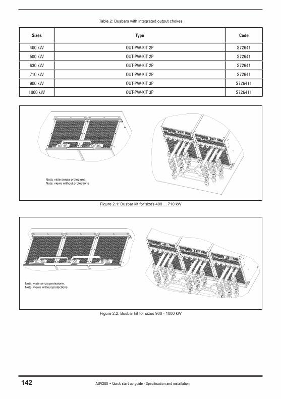
142 ADV200 • Quick start up guide - Specification and installation
Table 2: Busbars with integrated output chokes
Sizes Type Code
400 kW OUT-PW-KIT 2P S72641
500 kW OUT-PW-KIT 2P S72641
630 kW OUT-PW-KIT 2P S72641
710 kW OUT-PW-KIT 2P S72641
900 kW OUT-PW-KIT 3P S726411
1000 kW OUT-PW-KIT 3P S726411
Nota: viste senza protezione.Note: views without protections
Figure 2.1: Busbar kit for sizes 400 ... 710 kW
Nota: viste senza protezione.Note: views without protections
Figure 2.2: Busbar kit for sizes 900 - 1000 kW
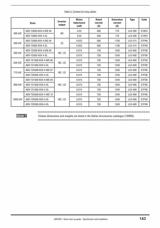
ADV200 • Quick start up guide - Specification and installation 143
Table 3: Chokes for long cables
SizesInverter output
Mains inductance
(mH)
Rated current
(A)
Saturation current
(A)
Type Code
400 kWADV-72000-KXX-4-MS 04
HD0.03 400 770 LU3-200 S7AF0
ADV-72000-XXX-4-SL 0.03 400 770 LU3-200 S7AF0
400 kWADV-72000-KXX-4-MS 04
LD0.022 580 1100 LU3-315 S7FH9
ADV-72000-XXX-4-SL 0.022 580 1100 LU3-315 S7FH9
500 kWADV-72500-KXX-4-MS 05
HD / LD0.015 730 1240 LU3-400 S7FO8
ADV-72500-XXX-4-SL 0.015 730 1240 LU3-400 S7FO8
630 kWADV-731500-KXX-4-MS 06
HD / LD0.015 730 1240 LU3-400 S7FO8
ADV-731500-XXX-4-SL 0.015 730 1240 LU3-400 S7FO8
710 kWADV-735500-KXX-4-MS 07
HD / LD0.015 730 1240 LU3-400 S7FO8
ADV-735500-XXX-4-SL 0.015 730 1240 LU3-400 S7FO8
900 kW
ADV-731500-KXX-4-MS 09
HD / LD
0.015 730 1240 LU3-400 S7FO8
ADV-731500-XXX-4-SL 0.015 730 1240 LU3-400 S7FO8
ADV-731500-XXX-4-SL 0.015 730 1240 LU3-400 S7FO8
1000 kW
ADV-735500-KXX-4-MS 10
HD / LD
0.015 730 1240 LU3-400 S7FO8
ADV-735500-XXX-4-SL 0.015 730 1240 LU3-400 S7FO8
ADV-735500-XXX-4-SL 0.015 730 1240 LU3-400 S7FO8
Note ! Chokes dimensions and weights are listed in the Gefran Accessories catalogue (1S9I09).
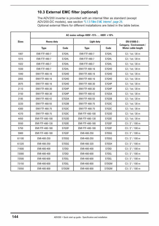
144 ADV200 • Quick start up guide - Specification and installation
10.3 External EMC fi lter (optional)The ADV200 inverter is provided with an internal fi lter as standard (except ADV200-DC models), see section “5.1.5 Filtro EMC interno”, page 29. Optional external fi lters for different installations are listed in the table below.
Sizes
AC mains voltage 400V -15% … 480V +10%
Heavy duty Light duty EN 61800-3 : Category / Environment /
Motor cable lengthType Code Type Code
1007 EMI FTF-480-7 S7GHL EMI FTF-480-7 S7GHL C2 / 1st / 30 m
1015 EMI FTF-480-7 S7GHL EMI FTF-480-7 S7GHL C2 / 1st / 30 m
1022 EMI FTF-480-7 S7GHL EMI FTF-480-7 S7GHL C2 / 1st / 30 m
1030 EMI FTF-480-7 S7GHL EMI FTF-480-16 S7GHO C2 / 1st / 30 m
1040 EMI FTF-480-16 S7GHO EMI FTF-480-16 S7GHO C2 / 1st / 30 m
2055 EMI FTF-480-16 S7GHO EMI FTF-480-16 S7GHO C2 / 1st / 30 m
2075 EMI FTF-480-16 S7GHO EMI FTF-480-30 S7GHP C2 / 1st / 30 m
2110 EMI FTF-480-30 S7GHP EMI FTF-480-30 S7GHP C2 / 1st / 30 m
3150 EMI FTF-480-30 S7GHP EMI FTF-480-42 S7GOA C2 / 1st / 30 m
3185 EMI FTF-480-42 S7GOA EMI FTF-480-55 S7GOB C2 / 1st / 30 m
3220 EMI FTF-480-55 S7GOB EMI FTF-480-75 S7GOC C2 / 1st / 30 m
4300 EMI FTF-480-75 S7GOC EMI FTF-480-75 S7GOC C2 / 1st / 30 m
4370 EMI FTF-480-75 S7GOC EMI FTF-480-100 S7GOD C2 / 1st / 30 m
4450 EMI FTF-480-100 S7GOD EMI FTF-480-130 S7GOE C2 / 1st / 30 m
5550 EMI FTF-480-130 S7GOE EMI FTF-480-180 S7GOF C3 / 2° / 100 m
5750 EMI FTF-480-180 S7GOF EMI FTF-480-180 S7GOF C3 / 2° / 100 m
5900 EMI FTF-480-180 S7GOF EMI-480-250 S7DGG C3 / 2° / 100 m
61100 EMI-480-250 S7DGG EMI-480-250 S7DGG C3 / 2° / 100 m
61320 EMI-480-250 S7DGG EMI-480-320 S7DGH C3 / 2° / 100 m
71600 EMI-480-400 S7DGI EMI-480-400 S7DGI C3 / 2° / 100 m
72000 EMI-480-400 S7DGI EMI-480-600 S7DGL C3 / 2° / 100 m
72500 EMI-480-600 S7DGL EMI-480-600 S7DGL C3 / 2° / 100 m
73150 EMI-480-600 S7DGL EMI-480-800 S7DGM C3 / 2° / 100 m
73550 EMI-480-800 S7DGM EMI-480-800 S7DGM C3 / 2° / 100 m
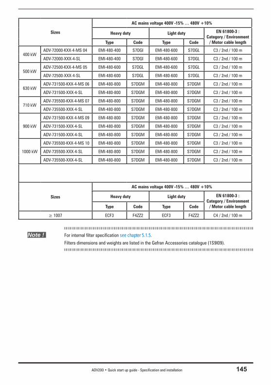
ADV200 • Quick start up guide - Specification and installation 145
Sizes
AC mains voltage 400V -15% … 480V +10%
Heavy duty Light duty EN 61800-3 : Category / Environment
/ Motor cable lengthType Code Type Code
400 kWADV-72000-KXX-4-MS 04 EMI-480-400 S7DGI EMI-480-600 S7DGL C3 / 2nd / 100 m
ADV-72000-XXX-4-SL EMI-480-400 S7DGI EMI-480-600 S7DGL C3 / 2nd / 100 m
500 kWADV-72500-KXX-4-MS 05 EMI-480-600 S7DGL EMI-480-600 S7DGL C3 / 2nd / 100 m
ADV-72500-XXX-4-SL EMI-480-600 S7DGL EMI-480-600 S7DGL C3 / 2nd / 100 m
630 kWADV-731500-KXX-4-MS 06 EMI-480-800 S7DGM EMI-480-800 S7DGM C3 / 2nd / 100 m
ADV-731500-XXX-4-SL EMI-480-800 S7DGM EMI-480-800 S7DGM C3 / 2nd / 100 m
710 kWADV-735500-KXX-4-MS 07 EMI-480-800 S7DGM EMI-480-800 S7DGM C3 / 2nd / 100 m
ADV-735500-XXX-4-SL EMI-480-800 S7DGM EMI-480-800 S7DGM C3 / 2nd / 100 m
900 kW
ADV-731500-KXX-4-MS 09 EMI-480-800 S7DGM EMI-480-800 S7DGM C3 / 2nd / 100 m
ADV-731500-XXX-4-SL EMI-480-800 S7DGM EMI-480-800 S7DGM C3 / 2nd / 100 m
ADV-731500-XXX-4-SL EMI-480-800 S7DGM EMI-480-800 S7DGM C3 / 2nd / 100 m
1000 kW
ADV-735500-KXX-4-MS 10 EMI-480-800 S7DGM EMI-480-800 S7DGM C3 / 2nd / 100 m
ADV-735500-XXX-4-SL EMI-480-800 S7DGM EMI-480-800 S7DGM C3 / 2nd / 100 m
ADV-735500-XXX-4-SL EMI-480-800 S7DGM EMI-480-800 S7DGM C3 / 2nd / 100 m
Sizes
AC mains voltage 400V -15% … 480V +10%
Heavy duty Light duty EN 61800-3 : Category / Environment
/ Motor cable lengthType Code Type Code
≥ 1007 ECF3 F4ZZ2 ECF3 F4ZZ2 C4 / 2nd / 100 m
Note ! For internal filter specification see chapter 5.1.5.
Filters dimensions and weights are listed in the Gefran Accessories catalogue (1S9I09).
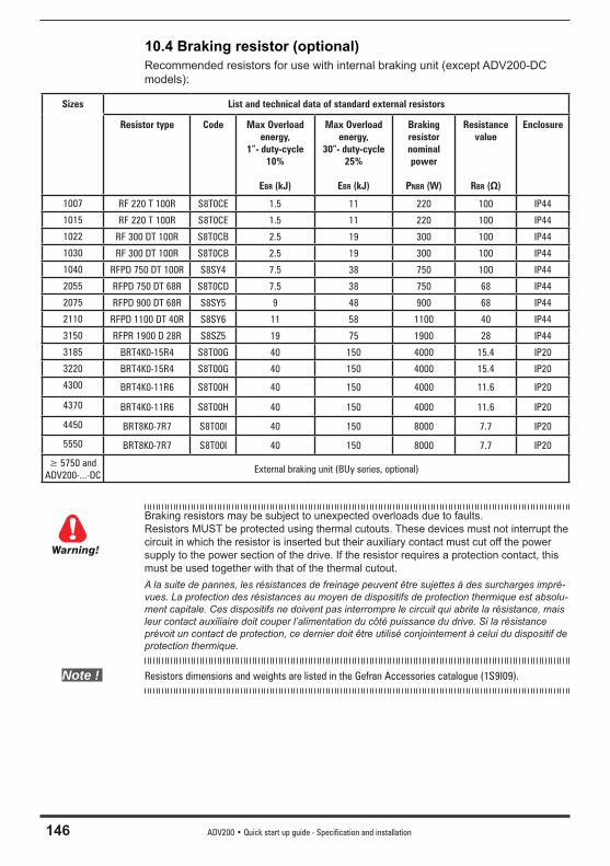
146 ADV200 • Quick start up guide - Specification and installation
10.4 Braking resistor (optional)Recommended resistors for use with internal braking unit (except ADV200-DC models):
Sizes List and technical data of standard external resistors
Resistor type Code Max Overload energy,
1”- duty-cycle 10%
EBR (kJ)
Max Overload energy,
30”- duty-cycle 25%
EBR (kJ)
Braking resistor nominal power
PNBR (W)
Resistance value
RBR (Ω)
Enclosure
1007 RF 220 T 100R S8T0CE 1.5 11 220 100 IP44
1015 RF 220 T 100R S8T0CE 1.5 11 220 100 IP44
1022 RF 300 DT 100R S8T0CB 2.5 19 300 100 IP44
1030 RF 300 DT 100R S8T0CB 2.5 19 300 100 IP44
1040 RFPD 750 DT 100R S8SY4 7.5 38 750 100 IP44
2055 RFPD 750 DT 68R S8T0CD 7.5 38 750 68 IP44
2075 RFPD 900 DT 68R S8SY5 9 48 900 68 IP44
2110 RFPD 1100 DT 40R S8SY6 11 58 1100 40 IP44
3150 RFPR 1900 D 28R S8SZ5 19 75 1900 28 IP44
3185 BRT4K0-15R4 S8T00G 40 150 4000 15.4 IP20
3220 BRT4K0-15R4 S8T00G 40 150 4000 15.4 IP20
4300 BRT4K0-11R6 S8T00H 40 150 4000 11.6 IP20
4370 BRT4K0-11R6 S8T00H 40 150 4000 11.6 IP20
4450 BRT8K0-7R7 S8T00I 40 150 8000 7.7 IP20
5550 BRT8K0-7R7 S8T00I 40 150 8000 7.7 IP20
≥ 5750 and ADV200-...-DC
External braking unit (BUy series, optional)
Braking resistors may be subject to unexpected overloads due to faults.Resistors MUST be protected using thermal cutouts. These devices must not interrupt the circuit in which the resistor is inserted but their auxiliary contact must cut off the power supply to the power section of the drive. If the resistor requires a protection contact, this must be used together with that of the thermal cutout.A la suite de pannes, les résistances de freinage peuvent être sujettes à des surcharges impré-vues. La protection des résistances au moyen de dispositifs de protection thermique est absolu-ment capitale. Ces dispositifs ne doivent pas interrompre le circuit qui abrite la résistance, mais leur contact auxiliaire doit couper l’alimentation du côté puissance du drive. Si la résistance prévoit un contact de protection, ce dernier doit être utilisé conjointement à celui du dispositif de protection thermique.
Note ! Resistors dimensions and weights are listed in the Gefran Accessories catalogue (1S9I09).
Warning!
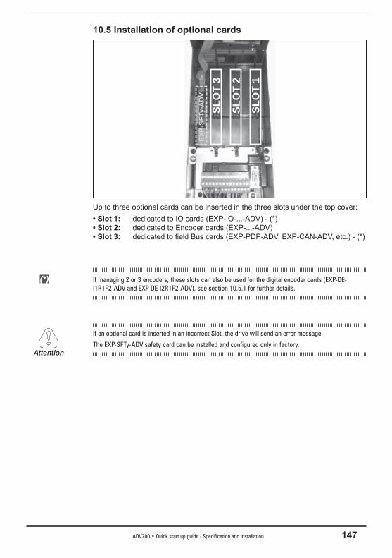
ADV200 • Quick start up guide - Specification and installation 147
10.5 Installation of optional cards
SLO
T 1
SLO
T 2
SLO
T 3
EXP-
SFTy
-AD
VUp to three optional cards can be inserted in the three slots under the top cover:• Slot 1: dedicated to IO cards (EXP-IO-...-ADV) - (*)• Slot 2: dedicated to Encoder cards (EXP-...-ADV)• Slot 3: dedicated to fi eld Bus cards (EXP-PDP-ADV, EXP-CAN-ADV, etc.) - (*)
(*) If managing 2 or 3 encoders, these slots can also be used for the digital encoder cards (EXP-DE-I1R1F2-ADV and EXP-DE-I2R1F2-ADV), see section 10.5.1 for further details.
If an optional card is inserted in an incorrect Slot, the drive will send an error message.
The EXP-SFTy-ADV safety card can be installed and configured only in factory. Attention
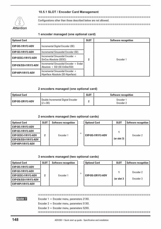
148 ADV200 • Quick start up guide - Specification and installation
10.5.1 SLOT / Encoder Card Management
Configurations other than those described below are not allowed.
1 encoder managed (one optional card)
Optional Card SLOT Software recognition
EXP-DE-I1R1F2-ADV Incremental Digital Encoder (DE)
2 Encoder 1
EXP-SE-I1R1F2-ADV Incremental Sinusoidal Encoder (SE)
EXP-SESC-I1R1F2-ADVIncremental Sinusoidal Encoder + SinCos Absolute (SESC)
EXP-EN/SSI-I1R1F2-ADVIncremental Sinusoidal Encoder + Endat Absolute + SSI (SE-EnDat/SSI)
EXP-HIP-I1R1F2-ADVIncremental Sinusoidal Encoder + Hiperface Absolute (SE-Hiperface)
2 encoders managed (one optional card)
Optional Card SLOT Software recognition
EXP-DE-I2R1F2-ADVDouble Incremental Digital Encoder (2 x DE)
2Encoder 1Encoder 2
2 encoders managed (two optional cards)
Optional Card SLOT Software recognition
+
Optional Card SLOT Software recognition
EXP-DE-I1R1F2-ADV
2 Encoder 1 EXP-DE-I1R1F2-ADV1
(or slot 3)Encoder 2
EXP-SE-I1R1F2-ADV
EXP-SESC-I1R1F2-ADV
EXP-EN/SSI-I1R1F2-ADV
EXP-HIP-I1R1F2-ADV
3 encoders managed (two optional cards)
Optional Card SLOT Software recognition
+
Optional Card SLOT Software recognition
EXP-DE-I1R1F2-ADV
2 Encoder 1 EXP-DE-I2R1F2-ADV1
(or slot 3
Encoder 2
Encoder 3
EXP-SE-I1R1F2-ADV
EXP-SESC-I1R1F2-ADV
EXP-EN/SSI-I1R1F2-ADV
EXP-HIP-I1R1F2-ADV
Note ! Encoder 1 = Encoder menu, parameters 21XX.
Encoder 2 = Encoder menu, parameters 51XX.
Encoder 3 = Encoder menu, parameters 52XX.
Attention

ADV200 • Quick start up guide - Specification and installation 149
10.5.2 Procedure 1. Remove the bottom cover as indicated in paragraph 5.2.1.
B B
C
2. To remove the top cover, loosen screws B by about 2 turns and slide out cover C as shown in the fi gure.
3. To prevent damage to the connection of the keypad, the top cover can be positioned as indicated in the fi gure.
Alternatively, remove the connector of the keypad and rest the cover in a safe place.
S1 (x1)
S2 (x2)
S2 (x2)
S1 (x1)
S1 (x1)
S2 (x2)
(S)
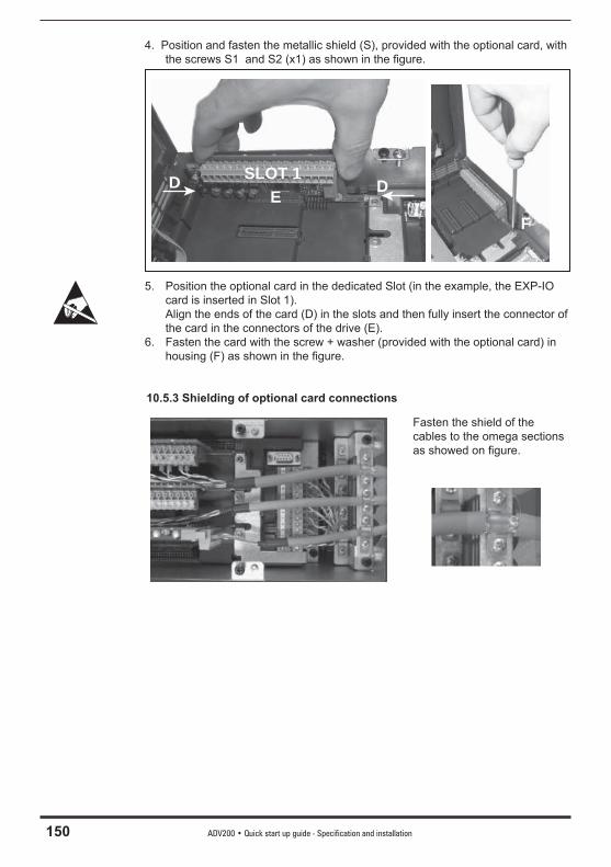
150 ADV200 • Quick start up guide - Specification and installation
4. Position and fasten the metallic shield (S), provided with the optional card, with the screws S1 and S2 (x1) as shown in the fi gure.
SLOT 1DD
EF
5. Position the optional card in the dedicated Slot (in the example, the EXP-IO card is inserted in Slot 1).
Align the ends of the card (D) in the slots and then fully insert the connector of the card in the connectors of the drive (E).
6. Fasten the card with the screw + washer (provided with the optional card) in housing (F) as shown in the fi gure.
10.5.3 Shielding of optional card connections
Fasten the shield of the cables to the omega sections as showed on fi gure.
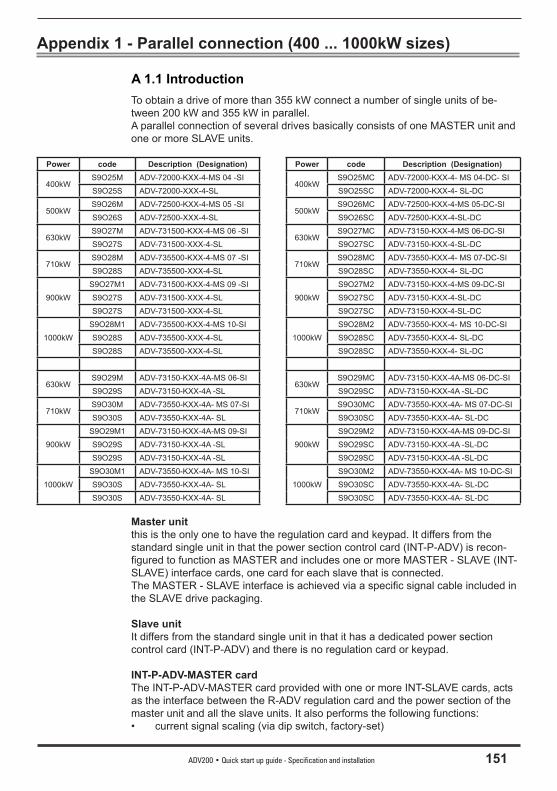
ADV200 • Quick start up guide - Specification and installation 151
Appendix 1 - Parallel connection (400 ... 1000kW sizes)
A 1.1 IntroductionTo obtain a drive of more than 355 kW connect a number of single units of be-tween 200 kW and 355 kW in parallel.A parallel connection of several drives basically consists of one MASTER unit and one or more SLAVE units.
Power code Description (Designation) Power code Description (Designation)
400kWS9O25M ADV-72000-KXX-4-MS 04 -SI
400kWS9O25MC ADV-72000-KXX-4- MS 04-DC- SI
S9O25S ADV-72000-XXX-4-SL S9O25SC ADV-72000-KXX-4- SL-DC
500kWS9O26M ADV-72500-KXX-4-MS 05 -SI
500kWS9O26MC ADV-72500-KXX-4-MS 05-DC-SI
S9O26S ADV-72500-XXX-4-SL S9O26SC ADV-72500-KXX-4-SL-DC
630kWS9O27M ADV-731500-KXX-4-MS 06 -SI
630kWS9O27MC ADV-73150-KXX-4-MS 06-DC-SI
S9O27S ADV-731500-XXX-4-SL S9O27SC ADV-73150-KXX-4-SL-DC
710kWS9O28M ADV-735500-KXX-4-MS 07 -SI
710kWS9O28MC ADV-73550-KXX-4- MS 07-DC-SI
S9O28S ADV-735500-XXX-4-SL S9O28SC ADV-73550-KXX-4- SL-DC
900kW
S9O27M1 ADV-731500-KXX-4-MS 09 -SI
900kW
S9O27M2 ADV-73150-KXX-4-MS 09-DC-SI
S9O27S ADV-731500-XXX-4-SL S9O27SC ADV-73150-KXX-4-SL-DC
S9O27S ADV-731500-XXX-4-SL S9O27SC ADV-73150-KXX-4-SL-DC
1000kW
S9O28M1 ADV-735500-KXX-4-MS 10-SI
1000kW
S9O28M2 ADV-73550-KXX-4- MS 10-DC-SI
S9O28S ADV-735500-XXX-4-SL S9O28SC ADV-73550-KXX-4- SL-DC
S9O28S ADV-735500-XXX-4-SL S9O28SC ADV-73550-KXX-4- SL-DC
630kWS9O29M ADV-73150-KXX-4A-MS 06-SI
630kWS9O29MC ADV-73150-KXX-4A-MS 06-DC-SI
S9O29S ADV-73150-KXX-4A -SL S9O29SC ADV-73150-KXX-4A -SL-DC
710kWS9O30M ADV-73550-KXX-4A- MS 07-SI
710kWS9O30MC ADV-73550-KXX-4A- MS 07-DC-SI
S9O30S ADV-73550-KXX-4A- SL S9O30SC ADV-73550-KXX-4A- SL-DC
900kW
S9O29M1 ADV-73150-KXX-4A-MS 09-SI
900kW
S9O29M2 ADV-73150-KXX-4A-MS 09-DC-SI
S9O29S ADV-73150-KXX-4A -SL S9O29SC ADV-73150-KXX-4A -SL-DC
S9O29S ADV-73150-KXX-4A -SL S9O29SC ADV-73150-KXX-4A -SL-DC
1000kW
S9O30M1 ADV-73550-KXX-4A- MS 10-SI
1000kW
S9O30M2 ADV-73550-KXX-4A- MS 10-DC-SI
S9O30S ADV-73550-KXX-4A- SL S9O30SC ADV-73550-KXX-4A- SL-DC
S9O30S ADV-73550-KXX-4A- SL S9O30SC ADV-73550-KXX-4A- SL-DC
Master unitthis is the only one to have the regulation card and keypad. It differs from the standard single unit in that the power section control card (INT-P-ADV) is recon-fi gured to function as MASTER and includes one or more MASTER - SLAVE (INT-SLAVE) interface cards, one card for each slave that is connected.The MASTER - SLAVE interface is achieved via a specifi c signal cable included in the SLAVE drive packaging.
Slave unitIt differs from the standard single unit in that it has a dedicated power section control card (INT-P-ADV) and there is no regulation card or keypad.
INT-P-ADV-MASTER cardThe INT-P-ADV-MASTER card provided with one or more INT-SLAVE cards, acts as the interface between the R-ADV regulation card and the power section of the master unit and all the slave units. It also performs the following functions:• current signal scaling (via dip switch, factory-set)
152 ADV200 • Quick start up guide - Specification and installation
• hardware dead time compensation• alarm signal management (including local diagnostics via LED)• temperature signal management.
INT-P-ADV-SLAVE cardThe INT-P-ADV-SLAVE card interfaces between the power section of the slave unit and the master unit. It also performs the following functions:• alarm signal management (including local diagnostics via LED)• temperature signal management.
INT-SLAVE cardThe INT-SLAVE interface card manages communication between a master unit and a slave unit. The INT-SLAVE cards are mounted on the master unit, their number correspond-ing to that of the slaves that are connected (max. 4 slaves).The INT-SLAVE card is factory-set.
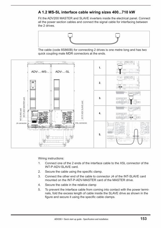
ADV200 • Quick start up guide - Specification and installation 153
A 1.2 MS-SL interface cable wiring sizes 400...710 kWFit the ADV200 MASTER and SLAVE inverters inside the electrical panel. Connect all the power section cables and connect the signal cable for interfacing between the 2 drives.
The cable (code 8S860B) for connecting 2 drives is one metre long and has two quick coupling male MDR connectors at the ends.
ADV-...-MS-.. ADV-...-SL
INT-
P-AD
V SL
AVE
card
INT-
SLAV
E ca
rd
XSL connectorJ4 connector
INT-
P-AD
V M
ASTE
R c
ard
1.
2.
3.
4.
5.
Wiring instructions:1. Connect one of the 2 ends of the interface cable to the XSL connector of the
INT-P-ADV-SLAVE card. 2. Secure the cable using the specifi c clamp.3. Connect the other end of the cable to connector J4 of the INT-SLAVE card
mounted on the INT-P-ADV-MASTER card of the MASTER drive.4. Secure the cable in the relative clamp5. To prevent the interface cable from coming into contact with the power termi-
nals, fold the excess length of cable inside the SLAVE drive as shown in the fi gure and secure it using the specifi c cable clamps.
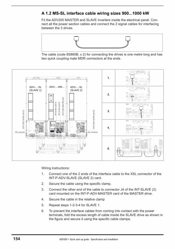
154 ADV200 • Quick start up guide - Specification and installation
A 1.2 MS-SL interface cable wiring sizes 900...1000 kWFit the ADV200 MASTER and SLAVE inverters inside the electrical panel. Con-nect all the power section cables and connect the 2 signal cables for interfacing between the 3 drives.
The cable (code 8S860B, x 2) for connecting the drives is one metre long and has two quick coupling male MDR connectors at the ends.
ADV-...-MS-.. ADV-...-SL (SLAVE 2)
ADV-...-SL (SLAVE 1)
INT-
P-A
DV
SLA
VE
car
d (2
)
XSL connector
INT-
P-A
DV
SLA
VE
car
d (1
)
XSL connector
INT-
SLA
VE
car
d (1
)
J4 connectors
INT-
P-A
DV
MA
STE
R c
ard
INT-
SLA
VE
car
d (2
)
1.
2.
3.
4.
6.
Wiring instructions:
1. Connect one of the 2 ends of the interface cable to the XSL connector of the INT-P-ADV-SLAVE (SLAVE 2) card.
2. Secure the cable using the specifi c clamp.
3. Connect the other end of the cable to connector J4 of the INT-SLAVE (2) card mounted on the INT-P-ADV-MASTER card of the MASTER drive.
4. Secure the cable in the relative clamp
5. Repeat steps 1-2-3-4 for SLAVE 1.
6. To prevent the interface cables from coming into contact with the power terminals, fold the excess length of cable inside the SLAVE drive as shown in the fi gure and secure it using the specifi c cable clamps.
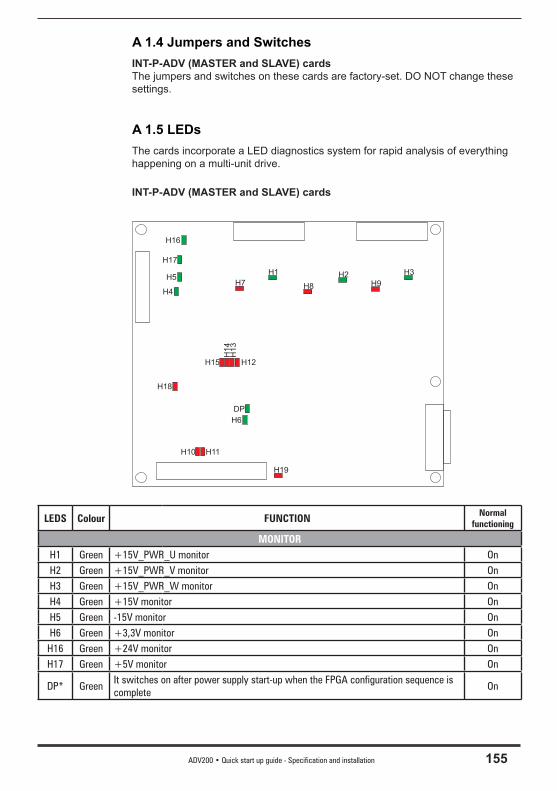
ADV200 • Quick start up guide - Specification and installation 155
A 1.4 Jumpers and SwitchesINT-P-ADV (MASTER and SLAVE) cardsThe jumpers and switches on these cards are factory-set. DO NOT change these settings.
A 1.5 LEDsThe cards incorporate a LED diagnostics system for rapid analysis of everything happening on a multi-unit drive.
INT-P-ADV (MASTER and SLAVE) cards
H2 H3
H6
H1H5
H17
H16
H4
DP
H7 H8 H9
H10 H11
H18
H15 H12
H1
4H
13
H19
LEDS Colour FUNCTION Normal functioning
MONITORH1 Green +15V_PWR_U monitor OnH2 Green +15V_PWR_V monitor OnH3 Green +15V_PWR_W monitor OnH4 Green +15V monitor OnH5 Green -15V monitor OnH6 Green +3,3V monitor OnH16 Green +24V monitor OnH17 Green +5V monitor On
DP* GreenIt switches on after power supply start-up when the FPGA configuration sequence is complete
On

156 ADV200 • Quick start up guide - Specification and installation
LEDS Colour FUNCTION Normal functioning
ALARMH7 Red PHASE U
They light up to indicate a short circuit between the output phasesOff
H8 Red PHASE V OffH9 Red PHASE W OffH10 Red It lights up to indicate a power rectifier heat sink overtemperature OffH11 Red It lights up to indicate overtemperature of the air inside the drive OffH12 Red IGBT U They light up to indicate loss of the feedback signal relating to the mo-
ment the IGBT devices are switched on. The signal is used for hardware dead time compensation
OffH13 Red IGBT V OffH14 Red IGBT W Off
H15 Red
It lights up in case of overtemperature of one of the IGBT devices.The signal temperature relating to the hotter of the master and slave IGBT devices is sent to the regulation card. A temperature signal is also sent automatically to the regulation card in case of mini-mum temperature, which could occur in the event of a fault in one of the temperature reading circuits.The loss of one of the temperature signals is indicated by LED H15, with the code indicated by the number of flashes (*): the sequence of flashes to indicate the faulty PHASE or SLAVE has a 3Hz frequency and is repeated cyclically every 5 seconds.
Off
H18 Red
It lights up on the INT-P-ADV MASTER card to indicate that the drive’s total current (master + slave) has exceeded the overcurrent value for the size of drive, whereas it lights up on the INT-P-ADV SLAVE card to indicate that the SLAVE current has only exceeded the overcurrent value of the SLAVE.
Off
H19 Red It lights up to indicate a fault on the DC-BUS power supply regulation card Off
(*) Led H15 code indicated by number of flashes NO. FLASHES
PHASE U 1
PHASE V 2
PHASE W 3
SLAVE 1 4
SLAVE 2 5
SLAVE 3 6
SLAVE 4 7
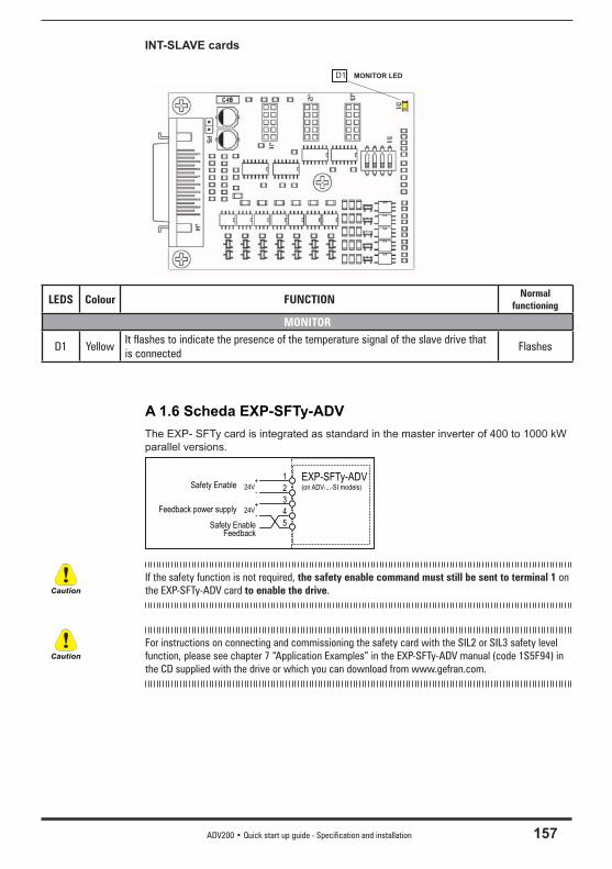
ADV200 • Quick start up guide - Specification and installation 157
INT-SLAVE cards
MONITOR LEDD1
LEDS Colour FUNCTION Normal functioning
MONITOR
D1 YellowIt flashes to indicate the presence of the temperature signal of the slave drive that is connected
Flashes
A 1.6 Scheda EXP-SFTy-ADVThe EXP- SFTy card is integrated as standard in the master inverter of 400 to 1000 kW parallel versions.
EXP-SFTy-ADV(on ADV-...-SI models)
1
2
3
4
5
24V+
-Safety Enable
24V+
-Feedback power supply
Safety EnableFeedback
If the safety function is not required, the safety enable command must still be sent to terminal 1 on the EXP-SFTy-ADV card to enable the drive.
For instructions on connecting and commissioning the safety card with the SIL2 or SIL3 safety level function, please see chapter 7 “Application Examples” in the EXP-SFTy-ADV manual (code 1S5F94) in the CD supplied with the drive or which you can download from www.gefran.com.
Caution
Caution
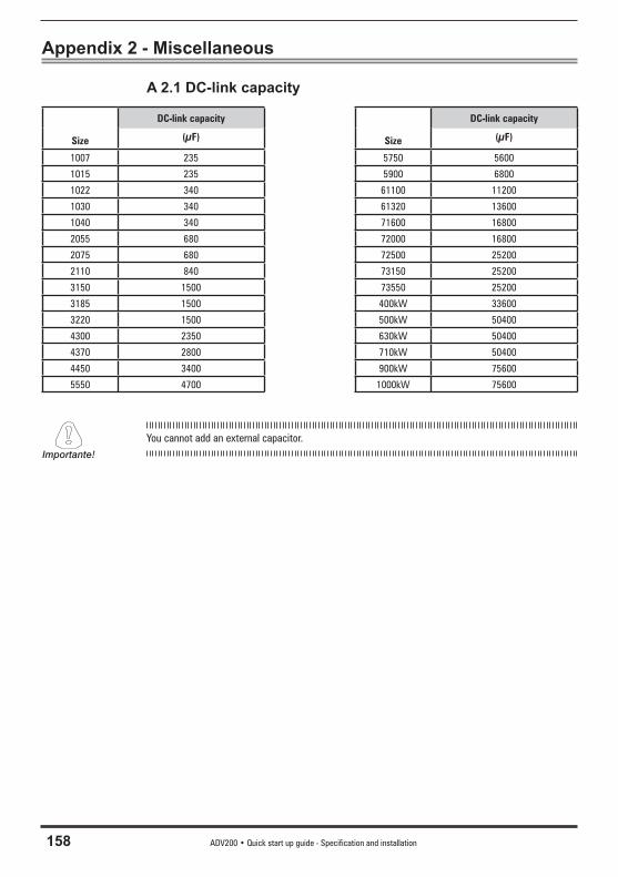
158 ADV200 • Quick start up guide - Specification and installation
Appendix 2 - Miscellaneous
A 2.1 DC-link capacity
Size
DC-link capacity
Size
DC-link capacity
(μF) (μF)
1007 235 5750 5600
1015 235 5900 6800
1022 340 61100 11200
1030 340 61320 13600
1040 340 71600 16800
2055 680 72000 16800
2075 680 72500 25200
2110 840 73150 25200
3150 1500 73550 25200
3185 1500 400kW 33600
3220 1500 500kW 50400
4300 2350 630kW 50400
4370 2800 710kW 50400
4450 3400 900kW 75600
5550 4700 1000kW 75600
You cannot add an external capacitor.Importante!
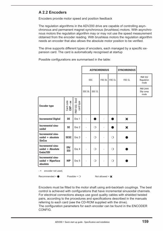
ADV200 • Quick start up guide - Specification and installation 159
A 2.2 EncodersEncoders provide motor speed and position feedback
The regulation algorithms in the ADV200 drive are capable of controlling asyn-chronous and permanent magnet synchronous (brushless) motors. With asynchro-nous motors the regulation algorithm may or may not use the speed measurement obtained from the encoder reading. With brushless motors the regulation algorithm needs an encoder that also allows the absolute motor position to be verifi ed.
The drive supports different types of encoders, each managed by a specifi c ex-pansion card. The card is automatically recognised at startup
Possible confi gurations are summarised in the table:
ASYNCHRONOUS SYNCHRONOUS
SSC FOC OL FOC CL FOC CLPAR 552
Regulation mode
SSC OL SSC CLPAR 2444Slip comp
mode
Encoder type
Card
cod
eEX
P –
xx
PAR
532,
Slo
t2
card
type
Incremental Digital DE Enc 1 - -
Incremental sinu-soidal
SE Enc 2 - -
Incremental sinu-soidal + absolute SinCos
SESC Enc 3 - -
Incremental sinu-soidal + Absolute Endat/SSI
EN/SSI
Enc 4 - -
Incremental sinu-soidal + Hiperface absolute
HIP Enc 5 - -
- = encoder not used,
Recommended = Possible = Not allowed =
Encoders must be fi tted to the motor shaft using anti-backlash couplings. The best control is achieved with confi gurations that have incremental sinusoidal channels.For electrical connections always use good quality cables with shielded twisted pairs, according to the procedures and specifi cations described in the manuals referring to each card (see the CD-ROM supplied with the drive).The confi guration parameters for each encoder can be found in the ENCODER CONFIG.

160 ADV200 • Quick start up guide - Specification and installation
In the event of an encoder malfunction the drive generates the Speed fbk back loss alarm and the cause of the malfunction is shown in parameter 2172 SpdFb-kLoss code.If the encoder is not used by the regulation algorithm the drive still manages the encoder position reading but does not generate an alarm in case of malfunctioning.
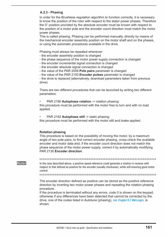
ADV200 • Quick start up guide - Specification and installation 161
A.2.3 - PhasingIn order for the Brushless regulation algorithm to function correctly, it is necessary to know the position of the rotor with respect to the stator power phases. Therefore the 0° position provided by the absolute encoder must be known with respect to the position of a motor pole and the encoder count direction must match the motor power phases.This is called phasing. Phasing can be performed manually, directly by means of the mechanical encoder assembly position on the motor shaft and on the phases, or using the automatic procedures available in the drive.
Phasing must always be repeated whenever:- the encoder assembly position is changed- the phase sequence of the motor power supply connection is changed- the encoder incremental signal connection is changed- the encoder absolute signal connection is changed- the value of the PAR 2008 Pole pairs parameter is changed- the value of the PAR 2100 Encoder pulses parameter is changed- the drive is replaced (alternatively, download parameters taken from previous drive)
There are two different procedures that can be launched by writing two different parameters:
• PAR 2190 Autophase rotation -> rotation phasing:this procedure must be performed with the motor free to turn and with no load applied.
• PAR 2192 Autophase still -> static phasing:this procedure must be performed with the motor still and brake applied.
Rotation phasingThis procedure is based on the possibility of moving the motor, by a maximum angle of two pole pairs, to fi nd correct encoder phasing, cross-check the available encoder and motor data and, if the encoder count direction does not match the phase sequence of the motor power supply, correct it by automatically modifying PAR 2130 Encoder direction.
Note! In the case described above, a positive speed reference could generate a rotation in reverse with respect to that defined as positive for the encoder (usually clockwise), while still ensuring good motor control.
The encoder direction defi ned as positive can be stored as the positive reference direction by inverting two motor power phases and repeating the rotation phasing procedure.If the procedure is terminated without any errors, code 0 is shown on the keypad, otherwise if any differences have been detected that cannot be corrected by the drive, one of the codes listed in Autotune (phasing), see chapter 8.2 Messages, is shown.

162 ADV200 • Quick start up guide - Specification and installation
Possible faults:- faults in electric signals not detected with a “Speed fbk loss [22]” alarm- error in the PAR 2008 Pole pairs parameter setting - error in the PAR 2100 Encoder pulses parameter setting
Static phasingUsing this method, in which the motor cannot move, the encoder and motor data cannot be cross-checked to verify the matching of parameters or count direction.This condition must therefore be checked before launching the procedure.

Gef
ran
wo
rld
wid
e
GEFRAN S.p.A.Via Sebina 7425050 Provaglio d’Iseo (BS) ITALYPh. +39 030 98881Fax +39 030 [email protected]
Drive & Motion Control UnitVia Carducci 2421040 Gerenzano [VA] ITALYPh. +39 02 967601Fax +39 02 [email protected]
Technical Assistance : [email protected]
Customer Service : [email protected]. +39 02 96760500Fax +39 02 96760278
Man
uale
AD
V200
-EN
1.0
- 27-
6-20
12
1S
9H
49
GEFRAN BENELUXLammerdries-Zuid, 14AB-2250 OLENPh. +32 (0) 14248181Fax. +32 (0) [email protected]
GEFRAN BRASILELETROELETRÔNICAAvenida Dr. Altino Arantes,377/379 Vila Clementino04042-032 SÂO PAULO - SPPh. +55 (0) 1155851133Fax +55 (0) [email protected]
GEFRAN DEUTSCHLANDPhilipp-Reis-Straße 9a63500 SELIGENSTADTPh. +49 (0) 61828090Fax +49 (0) [email protected]
SIEI AREG - GERMANYGottlieb-Daimler-Strasse 17/3D-74385 PleidelsheimPh. +49 7144 89 736 0 Fax +49 7144 89 736 [email protected]
Gefran España C/ de Vic, 109-11108160 Montmeló (BARCELONA)Ph. +34 934982643Fax +34 935721571 [email protected]
GEFRAN FRANCE4, rue Jean Desparmet - BP 823769355 LYON Cedex 08Ph. +33 (0) 478770300Fax +33 (0) [email protected]
GEFRAN SUISSE SARue Fritz Courvoisier 402302 La Chaux-de-FondsPh. +41 (0) 329684955Fax +41 (0) 329683574offi [email protected]
GEFRAN - UK Ltd.Capital House, Hadley Park EastTELFORD, TF1 6QJ Ph. +44 (0) 845 2604555Fax +44 (0) 845 [email protected]
GEFRAN Inc.8 Lowell AvenueWINCHESTER - MA 01890Toll Free 1-888-888-4474Fax +1 (781) [email protected]
GEFRAN SIEI - ASIABlk. 30 Loyang way 03-19 Loyang Industrial Estate 508769 SINGAPORE Ph. +65 6 8418300 Fax. +65 6 7428300 [email protected]
GEFRAN TAIWANRm. 3, 9F., No.8, Ln. 157, Cihui 3rd St., Zhongli City,Taoyuan County 320, Taiwan (R.O.C.)Tel/Fax +886-3-4273697 [email protected]
GEFRAN SIEI Drives Technology (Shanghai) Co., Ltd.No. 1285, Bei He Road, Jiad-ing District, Shanghai, China 201807Ph. +86 21 69169898Fax +86 21 [email protected]
GEFRAN SIEI Electric (Shanghai) Pte. Ltd.No. 1285, Bei He Road Jiad-ing District, Shanghai, China 201807Ph. +86 21 69169898Fax +86 21 [email protected]
GEFRAN INDIA Pvt. LtdHead offi ce (Pune offi ce)Survey No: 182/1 KH, Bhukum, Paud road, Taluka – Mulshi, Pune - 411 042. MH, INDIAPh:+91-20-3939 4400Fax: +91-20-3939 [email protected]
Branch offi ce (Thane offi ce)403, Damodar Nivas, ‘B’ Cabin Road, Near Railway quarters, Naupada, Thane (W) 400 602 , MH, IndiaPh. +91-22-2533 8797Fax +91-22-2541 [email protected]
Branch offi ce (Ahmedabad Offi ce)20-A, Second Floor, Kala Purnam Building, Near Municipal Market, C. G. Road, Ahmedabad 380 019, Gujarat, IndiaPhone: +91-79-2640 3591Phone/Fax: +91-79-2640 [email protected]
Related Documents