SHOCK PROPAGATION AND FRACTURE IN 6061-T6 ALUMINUM FROM WAVE PROFILE MEASUREMENTS By W.M. Isbell D R. Christman Materials & Structures Laboratory Manufacturing Development General Motors Corporation Reproduced by the C LE AR I N G .1i 0 U S E for Federal Scientific &' Technical information Springfield Va. 22151

Welcome message from author
This document is posted to help you gain knowledge. Please leave a comment to let me know what you think about it! Share it to your friends and learn new things together.
Transcript
SHOCK PROPAGATION AND FRACTURE
IN 6061-T6 ALUMINUM
FROM WAVE PROFILE MEASUREMENTS
ByW. M. Isbell
D R. Christman
Materials & Structures LaboratoryManufacturing DevelopmentGeneral Motors Corporation
Reproduced by theC LE AR I N G .1i 0 U S E
for Federal Scientific &' Technicalinformation Springfield Va. 22151
DASA 2419
MSL - 69- 60
COPY No. --
SHOCK PROPAGATION AND FRACTURE
IN 6061-T6 ALUMINUM
FROM WAVE PROFILE MEASUREMENTS
This work sponsored by the DefenseAtomic Support Agency under NWERi
Subtosk AA 106
ByW.M. Isbell
D. R. Christman
Materials & Qtructtres Laboratory
Manufacturing Development
General Motors Corporation
1970, APRIL
Prepared For
D Irector
Defense Atomic Support Agency
Washington, D.C. 20305
Under Contract DASA 01-68-C-0114
A
MANUFACTURING DEVELOPMENT e GENERAL MOTORS CORPORATION
MSL-69-60
ABSTRACT
The use of high-resolution, time-resolved measurements of
rear surface velocity in shock loaded 6061-T6 aluminum is
discussed as a means of studying spall fracture. The in-
fluence of stress pulse shape, material temperature, maxi-
mum compressive stress and degree of fracture on free sur-
face motion is presented and correlated with maximum tensile
stress at the spall plane. A summary of dynamic properties
data (equation of state, elastic wave velocity, stress-strain-
strain rate behavior, spall threshold) and a brief discussion
on fracture in metals are also presented.
iii
MANUFACTURING DEVELOPMENT • GENERAL MOTORS CORPORATION
MSL-69-60
TABLE OF CONTENTS
Page
ABSTRACT iii
LIST OF ILLUSTRATIONS v
INTRODUCTION 1
MATERIAL PROPERTIES 2
FRACTURE 5
SPALLATION 6
WAVE PROFILE MEASUREMENTS 14
SUMMARY 31
REFERENCES 32
DISTRIBUTION LIST 34
DD FORM 1473 DOCUMENT CONTROL DATA & R&D 39
iv
MANUFACTURING DEVELOPMENT 0 GENERAL MOTORS COI PORATION
MSL-69-60
LIST OF ILLUSTRATIONS
Figure Page
1 Stress-Volume Equation of State for6061-T6 Aluminum at 250C 3
2 Elastic Wave V7elocities for 6061-T6Aluminum at 251C, Including PressureDependence (Isothermal)
3 Stress-Strain-Strain Rate Behavior for6061--T6 Aluminum in Compression 4
4 Spall Fractures in Ductile and BrittleMaterials, Optical Micrographs 8
5 Surfaces Created by Spall Fracture inDuctile and Brittle Materials, ScanningElectron Micrographs 9
6 Spall Fractures in 6061-T6 Aluminum at250C, Optical Micrographs 11
7 Incipient Spall in 6061-T6 Aluminum at25°C, Optical Micrographs 12
8 Spall Fracture Surface in 6061-T6 Aluminum,
Scanning Electron Micrographs 12
9 Spall Behavior in 6061-T6 Aluminum at 250C 13
10 Schematic of Experimental System for WaveProfile Measurements with a Laser VelocityInterferometer 15
11 Photograph of Target and Impactor AssemblyShowing a Copper Target with Fused Quartz"Window" and an Aluminized Fused QuartzImpactor Mounted in a Sabot 16
12 Laser Interferometer Shown Installed on100 mm Bore Diameter Compressed Gas Gun 17
13 Wave Interactions in Spall Test and ResultantVelocity and Stress History 18
V
MANUFACTURING DEVEtOPMENT 0 GENERAl. MOTORS CORPORATION
MSL-69-60
LIST OF ILLUSTRATIONS (Continued)
Figure Page
14 Free Surface Velocity Profile of
6061-T6 Aluminum at 153 0C 20
15 Relation of Pullback to Impact Velocityand Degree of Fracture (Percent FractureRefers to Fraction of Area ExhibitingCracks on a Projected Length Basis) 21
16 Wave Profiles fzr Spallation Tests Con-ducted at Velocities Near the Thresholdsfor Incipient and Complete Spall 23
17 Spall Profiles at Two Times of Loading 24
18 Behavior of Spall Signal for Three ImpactStresses Above the Spall Threshold 25
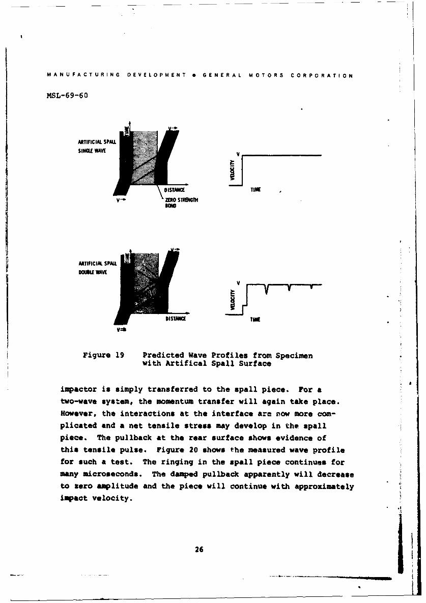
19 Predicted Wave Pr-files from Specimen
with Artifical Spall Surface 26
20 Measured Wave Profile for Artifical Spall 27
21 Qualitative Behavior of Aluminum Profilesat Elevated Temperatures 28
22 Three Waveshapes for Spall Studies 30
viI
MANUFACTURING DEVELOPMENT GENERAL MOTORS CORPORATION
MSL-69-60
INTRODUCTION
The prediction of the response of reentry vehicles to impul-
sive loading arising from energy deposition has been studied
extensively during the last decade. Sophisticated computer
routines have been developed to assess the vulnerability of
such vehicles to both the initial phase of the loading, in
which stress waves are propagated through the structure, and
'to subsequent phases, where elastic vibration or large perma-
nent deformation may occur.
The present study has been directed towards an examination of
the initial phase, where radiation-induced stresses may create
transient tensile pulses of such amplitude to induce fracture
in the material. The program has provided basic material pro-
perty measurements required under a larger, DASA sponsored,
research effort, PREDIX. Under this program, a large number
of dynamic measurements have been made on several classes of
materials and the results used as inputs for models of shock
wave propagation and fracture dynamics.
This report describes shock wave propagation and spall fracture
measurements made on 6061-T6 wrought aluninum alloy. The re-
port concentrates on interpretation of time-resolved, free
surface velocity measurements of impacted specimens and use
of these measurements as indicators of the complex fracture
process occurring within the specimen.
Work performed under Defense Atomic Support Agency contractDASA-01-68-C-0114.
. ...1
MANUFACTURING DEVELOPMENT e GENERAL MOTORS CORPORATION
MSL-69-60
MATERIAL PROPERTIES
Although this paper is primarily concerned with shock wave
propagation and spall fracture in 6061-T6 aluminum, the
material has been extensively characterized and representa-
tive results are presented here for completeness. 6061-T6
aluminum is a solution-heat-treated and precipitation-hardened
alloy (primarily aluminum-magnesium-silicon) and was obtained
in the form of rolled sheet with elongation of the grains in
the plane of the sheet. All testing was performed with the
test direction normal to the plane of the sheet. A summary
of mechanical and physical properties of 6061-T6 aluminum is
given in Reference 1.
The hugoniot and hydrostat have been determined from uniaxial
strain (shock wave) and uniaxial stress tests, the adiabat
has been obtained from ultrasonic measurements of elastic
wave velocities, and stress-strain-strain rate behavior has
been determined from uniaxial stress tests. The stress or
pressure vs volume change is given in Figure 1. The hugoniot
(aH ) is based on flat-plate, uniaxial strain experiments up
to 200 kbars. The indicated hugoniot elastic limit (oH - 6 kbars)
is based on measurements of elastic precursor decay and repre-
sents the level reached after % 5 mm travel. The hydrostat
(PH) was obtained from the hugoniot (oH) by subtracting the
deviatoric stress component (2 ). The adiabat (PS) was derived
from measurements of the pressure dependence (0-10 kbars) of
longitudinal and shear wave velocities, results of which are
given in Figure 2. The calculated bulk modulus (728 kbar)
and its adiabatic pressure derivative (4.6) were used to pre-(3)dict the dependence of volume on pressure The calculated
hydrostat and adiabat agree to within 1% up tc 200 kbar.
2

M ANU FA CT UR I NG DEVELOPMENT o GENERAL MO0TO0R S CO O0R ATIO 0N
MSL-69-60
100 - , .8a+ 7257n1+ 207? 2 aon(UH36 kbar)
z so PH 720 n 2?07? 2 5w3fl
-158.3 1fI-n -
1A 60
0. r Huqeniot
In Hydrostat N~
-, Miaat, Ps20-
- -- -- o Stress-Strain pathsItransmitted wave lest
00Me 0 0.06 03 0. 10
STRAIN. q*
Figure 1 Stress-Volume Equation of State for6061-T6 Aluminum at 250C
0 2 4 S tOI?3?
P. PMSStP( low)
Figjure 2 Elastic Wave Velocities for 606 1-T6Aluminum at 250C, Including PressureDependentce (Isothermal)
3
MANUFACTURING DEVELOPMENT * GENERAL MOTORS CORPORATION
* MSL-69-60
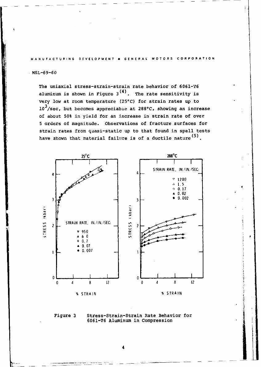
The uniaxial stress-strain-strain rate behavior of 6061-T6
aluminum is shown in Figure 3(4). The rate sensitivity is
very low at room temperature (25*C) for strain rates up to
103/sec, but becomes appreciable at 2880C, showing an increase
of about 50% in yield for an increase in strain rate of over
5 orders of magnitude. Observations of fracture surfaces for
strain rates from quasi-static up to that found in spall tests(5)have shown that material failure is of a ductile nature
25 C1 2880C
STRAIN RATE. IN.IIN./SEC:
I :1200I 1.5
* 0.17* 0.02
3 3 - * 0.002
LSTRAIN RATE, IN./IN/SEC:)
v950
-O0 0.IS0. 07
* 0. 07
01 0 .071
0 4 8 12 0 4 8 12
%STRAIN 1% STRAIN
Figure 3 Stress-Strain-Strain Rate Behavior for6061-T6 Aluminum in Compression
4
MANUFACTURING DEVELOPMENT 0 GENERAL MOTORS CORPORATION
MSL-69-60
FRACTURE
Fracture in metals can be considered to be of two types:
brittle or ductile. The type of fracture is related to the
physical and mechanical properties of the material, but is
also influenced by test temperature and loading history and
rate. When a metal is subjected to sufficient stress, then
slip, twinning or cleavage may occur, depending on which mode
has its critical value exceeded first by the resolved stress.
For a given metal, the relative values of these ttresses can
-change appreciably, particularly as a function of temperature
and crystal or grain orientation relative to applied stress.
Brittle fracture is characterized by transgranular cleavage
and often occurs in HCP and BCC structures, but usually not
in FCC metals. Crack nucleation in brittle fracture is associ-
ated with some degree of plastic deformation, which may be slip
on a microscopic scale as dislocations move to form pile-ups or
may be deformation twinning. Dislocation pile-ups can lead to
stress concentrations large enough to initiate cavities or mic-
rovoids at grain boundaries, slip bands, twins or other such
obstacles. These microcracks can coalesce and propagate under
the action of an applied stress, provided the elastic strain
energy is not dissipated by plastic flow.
Ductile fracture is usually characterized by nucleation,
growth and coalescence of voids or holes, giving a fibrous
surface consisting of relatively smooth, concave depressions
Voids often originate at stress concentrations resulting from
dislocation motion and pile-up at grain boundaries or imper-
. fections, or in regions of heavy plastic deformation. Sub-
sequent growth and coalescence of these voids is accumpanied
by a large amount of plastic flow. Uniform plastic strain in
5
MANUFACTURING DEVELOPMENT * GENERAL MOTORS CORPORATION
MSL-69-60
the direction of the applied stress gives normal rupture where
the resulting depressions are essentially circular. Shear
rupture occurs under the combined effects of plastic strain
in the applied stress direction and shear strain in the maxi-
mum shear stress plane. Tearing is the result of non-uniform
strain in the applied stress direction. Both shearing and
tearing result in elongated or parabolic dimples on fracture
surfaces.
SPALLATION
The tensile stress condition usually associated with spall
fracture results from reflection of compressive stress pulses
from a relatively low impedance interface (usually a free sur-
face) and their subsequent interaction. Analysis of spall
fracture in metals requires consideration of a number of fac-
tors, most important of which are material properties, stress-
time history and test technique. This section is concerned
with test techniques and some representative results.
There are a number of methods of generating stress or shock waves
of sufficient magnitude to create spall fractures in a material,(7)including gun-launched flat plates (7 electrically or magnetically
(8) (9)accelerated flyer plates (8 explosive loading (9 and x-rayV (10)or electron beam deposition 1 . The gun-launched, flat-platetechnique was used in conducting the shock wave and fracture
studies described in this paper. This method gives close
control over stress-time history of the input pulse, permitschange in the shape of the spall-producing tensile pulse, is
V Icompatible with the use of high-resolution diaqnostic techniques,and permits easy recovery of test specimens.
6
. MANUFACTURING DEVELOPMENT * GENERAL MOTORS CORPORATION
MSL-69-60
The spall behavior of a material is generally studied by car-
rying out a series of impact and recovery tests, where the tar-
get specimen is then sectioned across a diameter, polished,
etched and examined optically at a magnification of 50 to
10OX. The specimen is then graded or classified according
to the degree of fracture that has occured, which can range
from no observable fractures to complete material separation.
The incipient spall threshold is defined as the impact velocity
(for a given set of test parameters) corresponding to the onset
of microfracture. Occasionally, a few microcracks may appear
at lower velocities, but these appear to originate at material
flaws where conditions for fractuire initiation are not repre-
sentative of bulk material properties. Therefore, the incipient
threshold is based on cracking over approximately 50% of the
specimen (on a projected length basis). One could also estab-
lish a complete fracture or separation threshold, but this is
not recommended as a primary spall criterion since it is more
kk likely to be influenced by edge effects (loss of one-dimensionalstrain conditions) and by recovery-induced damage.
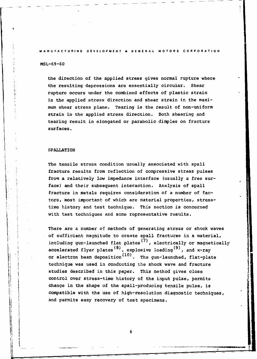
The nature of spall fractures in ductile and brittle metals is
shown in Figures 4 and 5. In Figure 4, tantalum shows a classic
form of ductile failure, i.e., formation of almost perfectly
spherical voids, while beryllium shows cleavage cracks typical
of brittle failure. The aluminum alloy has also failed in a
ductile manner, although the appearance of the fractures is
quite different from tantalum, possibly due to the elongated
structure and secondary constituents in the aluminum alloy.
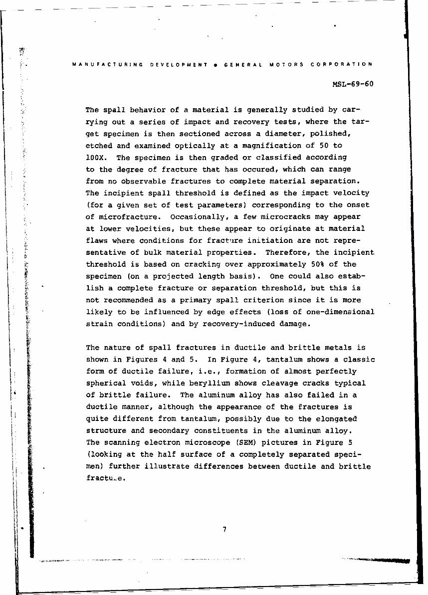
The scanning electron microscope (SEM) pictures in Figure 5
(looking at the half surface of a completely separated speci-
men) further illustrate differences between ductile and brittle
fractu-e.
7
M A N UFA CT U RING E V E LOP0M E NT 6 E NE RAL MO0TO0R S CO0RPO0R A TIO0N
MSL-69-60
EE
Woo
.9.
C4
4.J*
A . ~ -4 1 .19 .
4
4ii
8a
MANUFACTURING DEVELOPMENT * GENERAL MOTORS CORPORATION
MSL-69--60
coL
uJ 0)
>--
-d4,
04 (d,
Ito z
J (1.
'0 4J 4
0~0
1 °
Q rId
9 I
MANUFACTURING DEVELOPMENTS GENERAL MOTORS CORPORATION
MSL-69-60
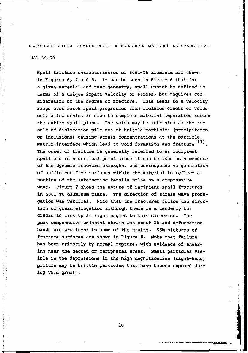
Spall fracture characteristics of 6061-T6 aluminum are shown
in Figures 6, 7 and 8. It can be seen in Figure 6 that for
a given material and test geometry, spall cannot be defined in
terms of a unique impact velocity or stress, but requires con-
sideration of the degree of fracture. This leads to a velocity
range over which spall progresses from isolated cracks or voids
only a few grains in size to complete material separation across
the entire spall plane. The voids may be initiated as the re-
sult of dislocation pile-ups at brittle particles (precipitates
or inclusions) causing stress concentrations at the particle-(11)matrix interface which lead to void formation and fracture
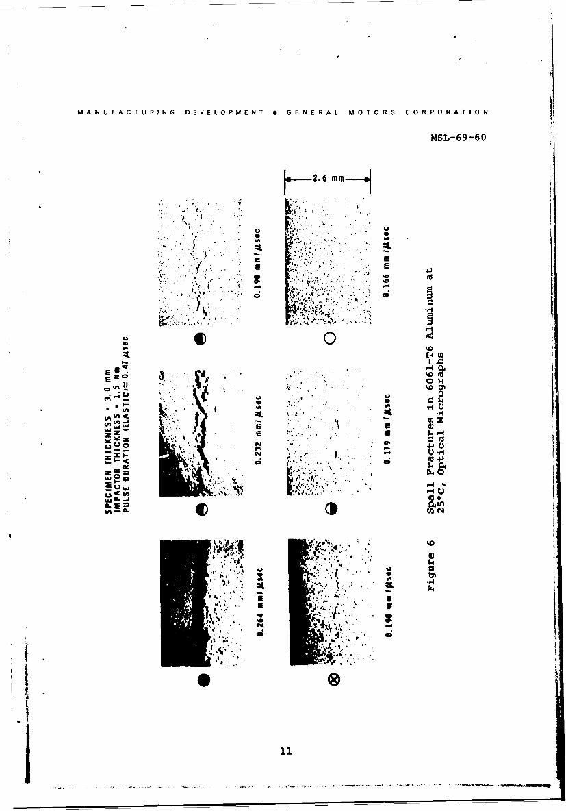
The onset of fracture is generally referred to as incipient
spall and is a critical point since it can be used as a measure
of the dynamic fracture strength, and corresponds to generation
of sufficient free surfaces within the material to reflect a
portion of the interacting tensile pulse as a compressive
wave. Figure 7 shows the nature of incipient spall fractures
in 6061-T6 aluminum plate. The direction of stress wave propa-
gation was vertical. Note that the fractures follow the direc-
tion of grain elongation although there is a tendency for
cracks to link up at right angles to this direction. The
peak compressive uniaxial strain was about 2% and deformation
bands are prominent in some of the grains. SEM pictures of
fracture surfaces are shown in Figure 8. Note that failure
has been primarily by normal rupture, with evidence of shear-
ing near the necked or peripheral areas. Small particles vis-
ible in the depressions in the high magnification (right-hand)
picture may be brittle particles that have become exposed dur-
ing void growth.
10
MAN UFACTURING DEVELOIPMENT *GENERAL MO0TO0R S COR POR A TIO0N
MSL-69-60
2.6 mm
E- W
%0(
E'D
V O$4
(d 0C9 14
z A4**
14
0411
M AN UF AC T UR ING DEVELOPMENT eGENERAL MO0TO0R S CO0R POR ATIO N
MSL-69-60
1.5 mm IMPACTOR--,3. 0 MM TARGET
0.190 mm Ipsec. (INCIPIENT SPALL)
0. 62i M 0. 25 mm
Figure 7 Incipient Spall in 6061-T6 Aluminum at250C, optical Micrographs
0.5mm-e.1.Omm I 0.36mmlos
Figure 8S pl rctr ufc in 6061-T6 Aluminum,
12
MANUFACTURING DEVELOPMENT 6 GENERAL MOTORS CORPORATION
MSL-69-60
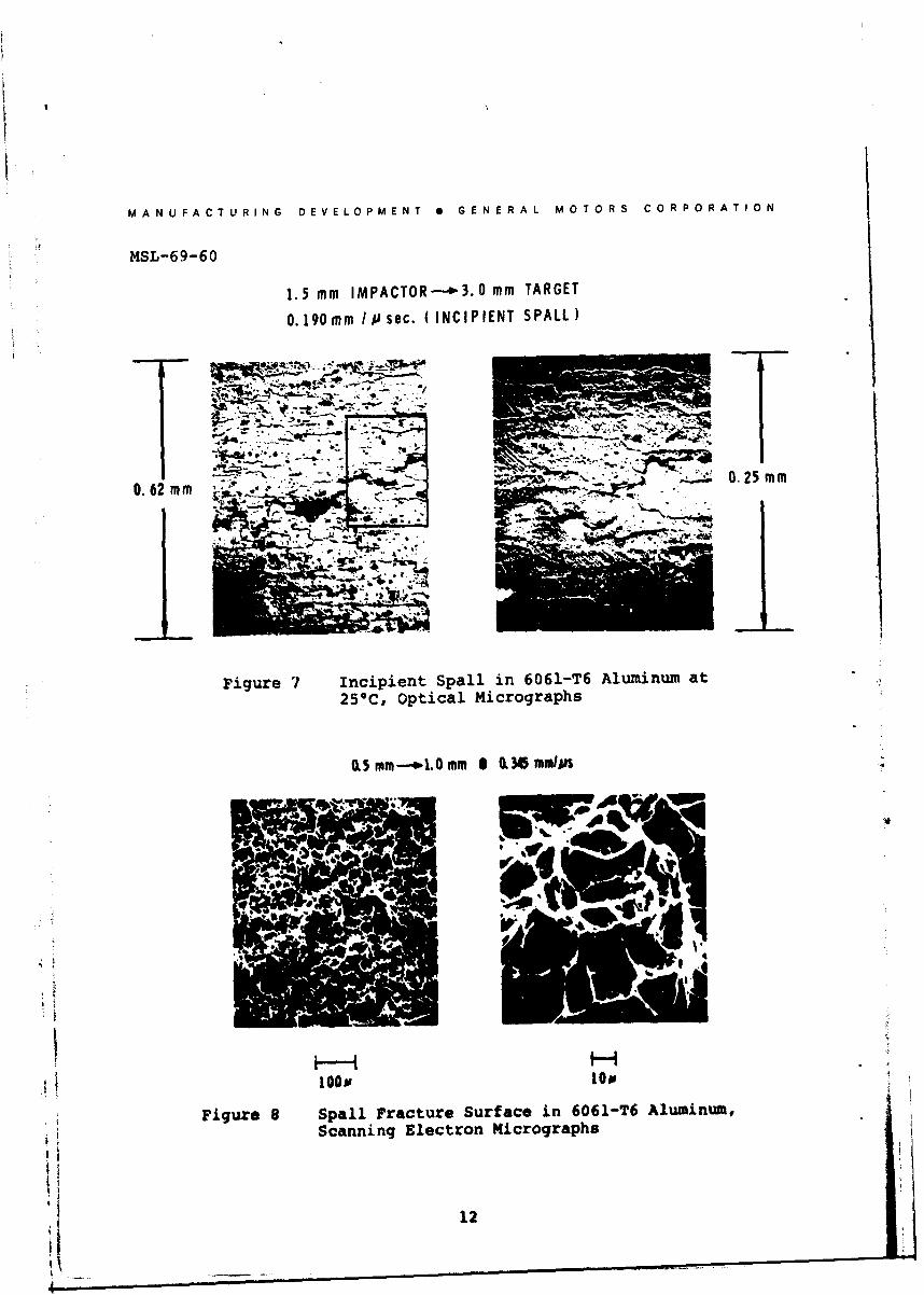
The "time dependence" of spallation is shown in Figure 9 for
6061-T6 aluminum sheet. Although data are presented in terms
of impact velocity vs impactor thickness for nominally rec-
tangular pulses, the results indicate that the onset of frac-
ture is a function of stress-time history, since impact velo-
city and impactor thickness are proportional to stress and
time of loading, respectively. This relationship has been
studied by a number of investigators and there is not yet
agreement on either a physical description of the fracture
process or its dependence on factors such as precompression,
stress rate, stress gradient, or tensile pulse magnitude andwidth (12-16)
* Cnple separation* Above Incipient
0.4 e Incipient spelle Below Incipient
0 0 o ocracks
-n i U
0
1.0 2.0 3.0 4.0i
p. PROJECTILE THICIU ISS I Wi
Figure 9 Spall Behavior in 6061-T6 Aluminum at 25*C
13
MANUFACTURING DEVELOPMENT 0 GENERAL MOTORS CORPORATION
MSL-69-60
Although passive spall tests (i.e., recovery tests) and graph-
ical presentation of data permit one to establish spall thres-
holds for a material, they do not provide a convenient method
of deducing stress-time history associated with a given test.
This requires use of active diagnostic instrumentation to mea-
sure wave profiles under spall producing conditions. Results
of such measurements are presented and discussed below, and
are intended to provide quantitative data on mechanisms of
spall fracture.
WAVE PROFILE MEASUREMENTS
Due to the difficulty of making high resolution measurements
of wave profiles within a shocked specimen, experimenters have
utilized time-resolved velocity measurements of the specimen
rear surface as an indicator of the behavior of the compres-
sive and release wave systems ( 1 7 ' 1 8 ) . Interpretation of freesurface velocity measurements, however, is complicated by the
necessity of predicting wave behavior within the material at
a spall *plane", which is actually a volume of material in
which time-dependent fract.xe occurs. To properly reconstruct
the wave profile, and wave interactions, it is necessary toassume a model of the material behavior. Measurements made
under varying impact conditions are used to assess the ac-
curacy of the model.
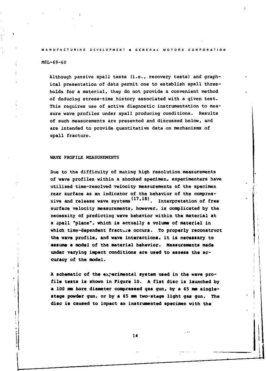
A schematic of the ekerimental system used in the wave pro-
file tests is shown in Figure 10. A flat disc is launched by
a 100 m bore diameter compressed gas gun, by a 65 am single-
stage powder gun, or by a 65 = two-staqe light gas gun. Thedisc is caused to impact an instrumented specimen with the
14
I rM mn w r l ,rm ~
MANUFACTURING DEVELOPMENT a GENERAL MOTORS CORPORATION
MSL-69-60
velocity controlled to ±1%. An array of electrically charged
pins placed around the specimen is used to measure imparcvelocity and planarity of impact (tilt) as well as tc start
instruments used to measure shock wave parameters. Standard
techniques are used in specimen design to assure a state of
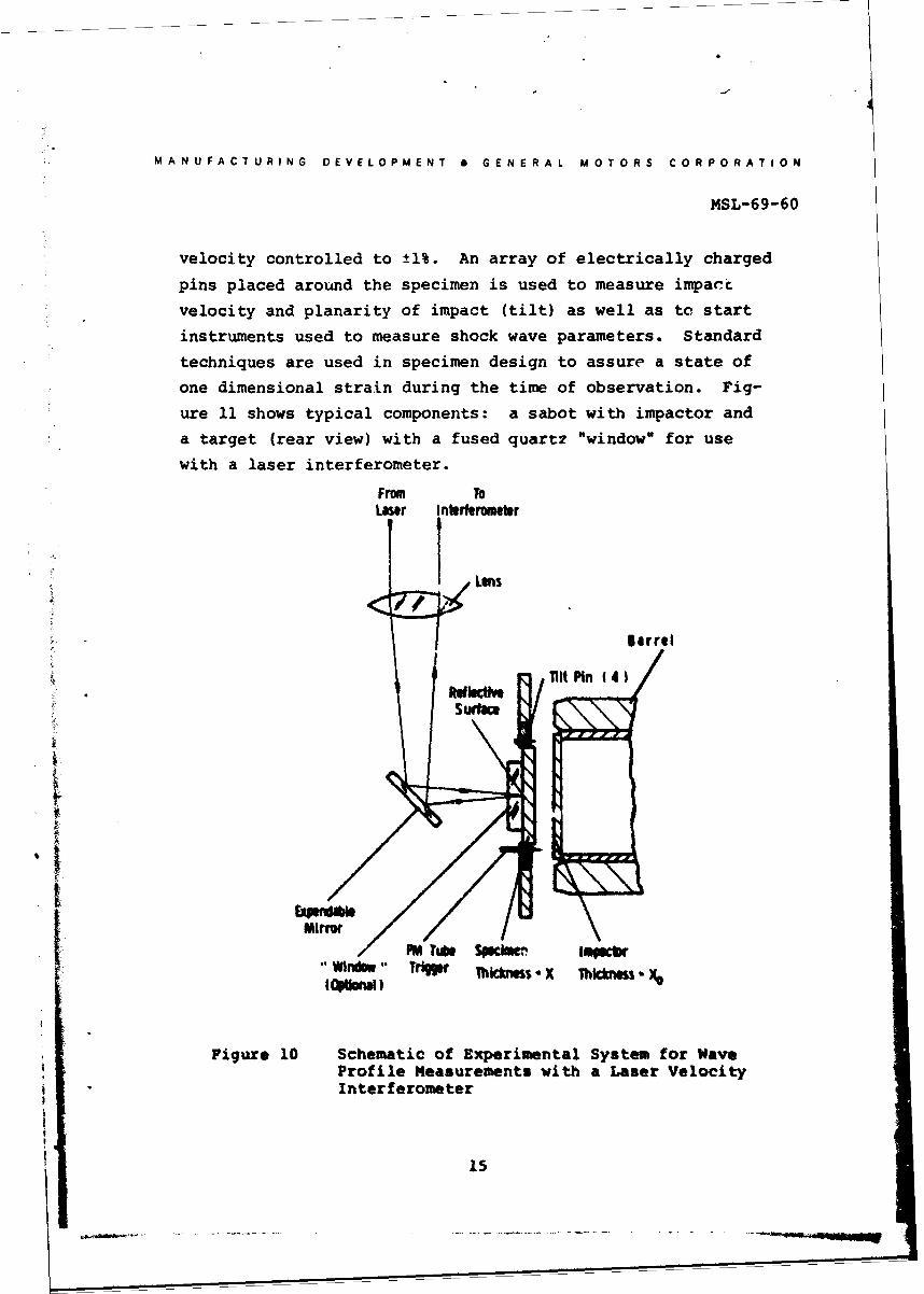
one dimensional strain during the time of observation. Fig-
ure 11 shows typical components: a sabot with impactor anda target (rear view) with a fused quartz "window" for use
with a laser interferometer.
From ToLaser Interferometer
( Lens
Barrel
lINt Pin (4
Surf"c
,Windo" T T ickness X Thickness
Figure 10 Schematic of Experimental System for WaveProfile Measurements with a Laser VelocityInterferometer
15
MANUFACTURING DEVELOPMENT * GENERAL MOTORS CORPORATION
MSL-69-60
Figure 11 Photograph of Target and Impactor AssemblyShowing a Copper Target with Fused Quartz"Window" and an Aluminized Fused QuartzImpactor Mounted in a Sabot
The laser velocity interferometer used to measure motion of
the rear surface of a shocked specimen has been discussed by
Barker (18 ). A single-phase gas laser is focused on the rear
surface of the specimen and the reflected beam is directed
through an interferometer system which responds to cl-nges
in surface velocity as changes in the fringe pattern focused
on a fast-response photomultiplier tube. The photomultiplier
output is recorded on oscillograms and analyzed to give the
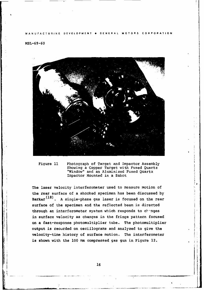
velocity-time history of surface motion. The interferometeris shown with the 100 mm compressed gas gun in Figure 12.
16
MAN U FACT URINS DEVELOPMENT * GENERAL MCTORS COR POHAT1ON
MSL-69-60
Figure 12 Laser Interferometer Shown Installed on100 mm Bore Diameter Compressed Gas Gun
For tests in which it is desired to reduce spall-producing
reflections, a transparent material of similar impedance to
the specimen is bonded to the rear surface and the interfero-
meter is focused on the specimen surface through the transpa-
rent "window". Changes in optical path length due to the
change in index of refraction of the window material as it
is traversed by the shock wave are incorporated into the
analysis..
I The interferometer system is capable of extremely high time
and spacial resolution (2-5 nsec and 0.2 microns) and mea-
surements using Lhis system are relatively insensitive to
17 1*
MANUFACTURING DEVELOPMENT 0 GENERAL MCTORS CORPORATION
MSL-69-60
shock wave tilt, the nemesis of manganin wire, x-cut quartz,
variable capacitor, and other systems used to measure wave
profiles. Data are obtainable up to stresses where the sur-
face reflectivity is seriously degraded by the action of the
shock wave (100-200 kbars for many materials).
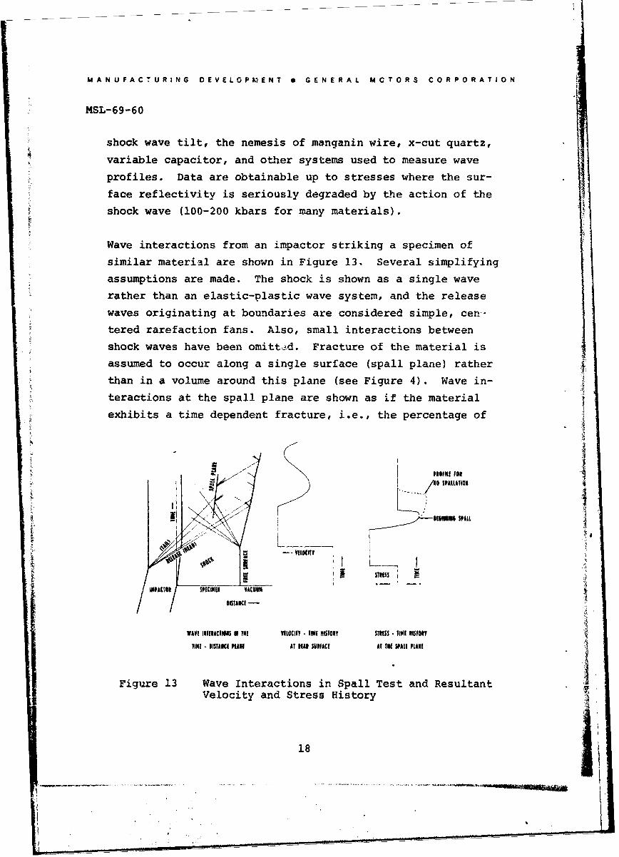
Wave interactions from an impactor striking a specimen of
similar material are shown in Figure 13. Several simplifying
assumptions are made. The shock is shown as a single wave
rather than an elastic-plastic wave system, and the release
waves originating at boundaries are considered simple, cen-
tered rarefaction fans. Also, small interactions between
shock waves have been omitted. Fracture of the material isassumed to occur along a single surface (spall plane) rather
than in a volume around this plane (see Figure 4). Wave in-
teractions at the spall plane are shown as if the material
exhibits a time dependent fracture, i.e., the percentage of
S1011FLE 1O
1PAITON
N.N.16 01 E SNNN PALL
I,--VELCKITY
I STIES!INPAtON SPECIMEN VACUU.. .
DISTAN CE EA
WAVE INTERACTIONS IN IN[ VELOCITY TIME 11TO1Y STIESS TIME NISTONYIlNI DISTANCE PLANE AT HEAN SURFACE AT IN[ SPARL PLANE
Figure 13 Wave Interactions in Spall Test and ResultantVelocity and Stress History
18
MANUFACTURING DEVELOPMENT 0 GENERAL MOTORS CORPORATION
MSL-69-60
fractured area in the spall plane increases with time until
the entire spall surface has separated. During the early
stages of the fracture process, before complete separation
is achieved, waves crossing the spall plane are partially
transmitted and partially reflected. After complete separa-
tion has occurred, any waves trapped in the spalled piece i
reverberate, giving a decaying, sinusoidal motion to the
rear surface as the wave is damped by viscous forces. The
magnitude of the exponential decay constant may be related(17)to dislocation processes as described by Taylor
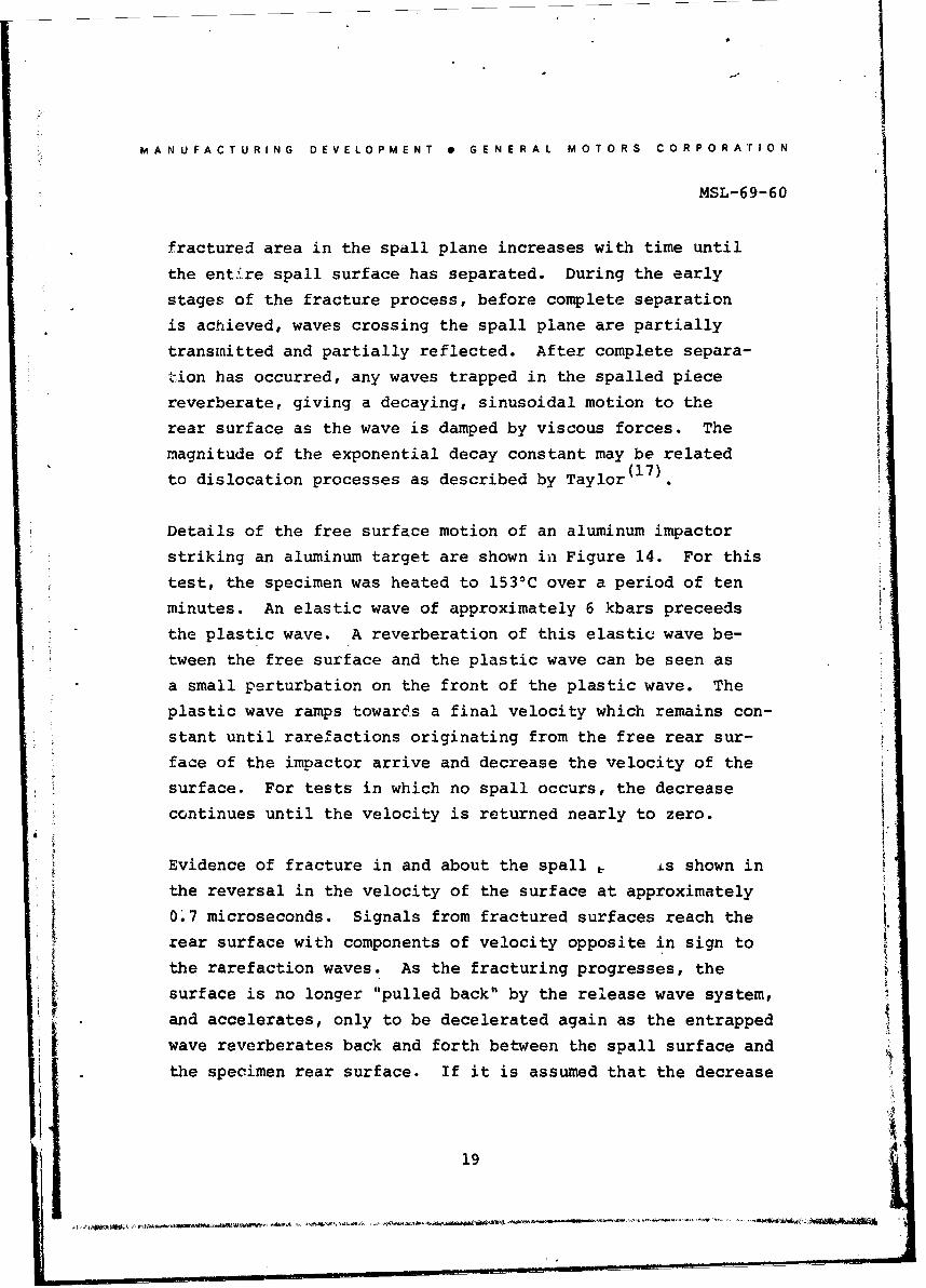
Details of the free surface motion of an aluminum impactor
striking an aluminum target are shown in Figure 14. For this
test, the specimen was heated to 153 0C over a period of ten
minutes. An elastic wave of approximately 6 kbars preceeds
the plastic wave. A reverberation of this elastic wave be-
tween the free surface and the plastic wave can be seen as
a small perturbation on the front of the plastic wave. The
plastic wave ramps towards a final velocity which remains con-
stant until rarefactions originating from the free rear sur-
face of the impactor arrive and decrease the velocity of the
surface. For tests in which no spall occurs, the decrease
continues until the velocity is returned nearly to zero.
Evidence of fracture in and about the spall i is shown in
the reversal in the velocity of the surface at approximately
0'7 microseconds. Signals from fractured surfaces reach the
rear surface with components of velocity opposite in sign to
the rarefaction waves. As the fracturing progresses, the
surface is no longer "pulled back" by the release wave system,
and accelerates, only to be decelerated again as the entrapped
wave reverberates back and forth between the spall surface and
the specimen rear surface. If it is assumed that the decrease
19
MANUFACTURING DEVELOPMENT S GENERAL MOTORS CORPORATION
MSL-69-60
of the free surface velocity to the point of reversal (referred
to as "pullback") is related to the maximum tensile stress at
the spall plane, a quantitative measure of the negative stress
required to fracture the material for a given waveshape is
provided by the profile. The functional form of the relation-
ship between the maximum tensile stress and pullback has not
been firmly established, but attempts to correlate experimentalresults with calculations of spall plane stress have resulted
in the following (17 ,19)
a = pc -C (1)
where at is maximum tensile stressat the spall plane, p and C are localdensity and longitudinal velocity, andAV is pullback.
0. 0 I ' I i ! I I ... l 5 I ' I ' I ' I
X. •1.56mm
0.O0 X • 2.78mmChV 0.263mmlps
&.50
0.0 Compressineve systm Release wve syslem
Elastic
0.30 Pli / .ontlel dwy d
Pink w . _Jringing In spell i
6 0.20
0.C 0.20 0.40 0.60 0.80 1.00 1.20 1.40 1.40 1.0TIME IN MICROSECONDS
Figure 14 Free Surface Velocity Profile of6061-T6 Aluminum at 1530C
20
MANUFACTURING DEVELOPMENT S GENERAl. MOTORS CORPORATION
MSL-69-60
It should be noted that the calculations that have been com-
pared with Equation 1 are subject to some uncertainties, par-
ticularly with regard to the negative pressure equation of
state, the fracture mechanism, and the loss of uniaxial strain
conditions in the spall plane.
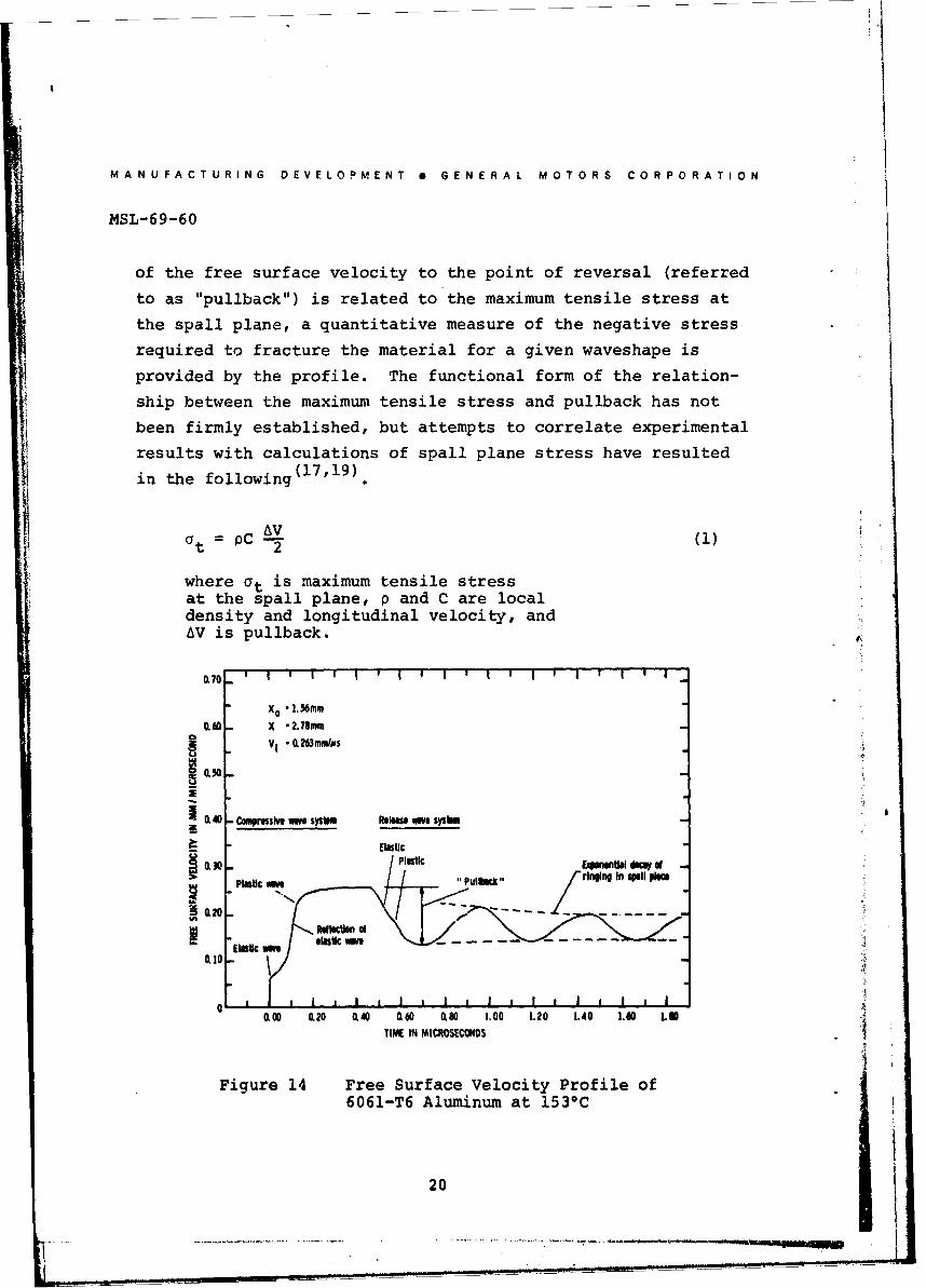
The pullback has been found to be relatively insensitive to
the maximum compressive stress as well as to the degree of
fracture at the spall plane, for a given impactor thickness.
Pullback data corresponding to impact stresses of 15 to 40
kbars are shown in Figure 15. (The results in both Figures 15
Fraurs
-0% Fracture
1.20 COS Fracure
jjjll iP/SIlir
-//"& 135 - _ 10 1-
I I I I i
CLIO Y4O 2m
I 10 120 1.30 1.0 130o to
IMPACT VLOCITY (M Ioli I
Figure 15 Relation of Pullback to Impact Velocity and Degreeof Fracture (Percent Fracture Refers to Fraction ofArea Exhibiting Cracks on a Projected Length Basis)
and 16 are for 1.5 mm impactors). In the elastic range, pull-
back equals impact velocity, while at impact velocities caus-ing fracture, the pullback is approximately 0.135 mm/psec.
(independent o degree of fracture and maximum stress), cor-
responding to 12 kbars (Equation 1). Thus, the pullback
appears to be associated with the incipient spall threshold,
i.e., the formation and initial coalescence of voids in the
21
MANUFACTURING DEVELOPMENT e GENERAL MOTORS CORPORATION
MSL-69-60
material, rather than with complete fracture or separation.
This useful conclusion may allow comparison of the dynamic
fracture strength of the material over a range of wave shapes
and times of loading without the necessity of conducting all
tests with exactly the same degree of final fracture. An
additional benefit may result if the pullback can be related
to the results of the recovery-type measurements of the incip-
ient spall threshold. Then a single wave profile test could,
for a given set of initial conditions, provide the same incip-ient threshold data as a series of recovery tests.
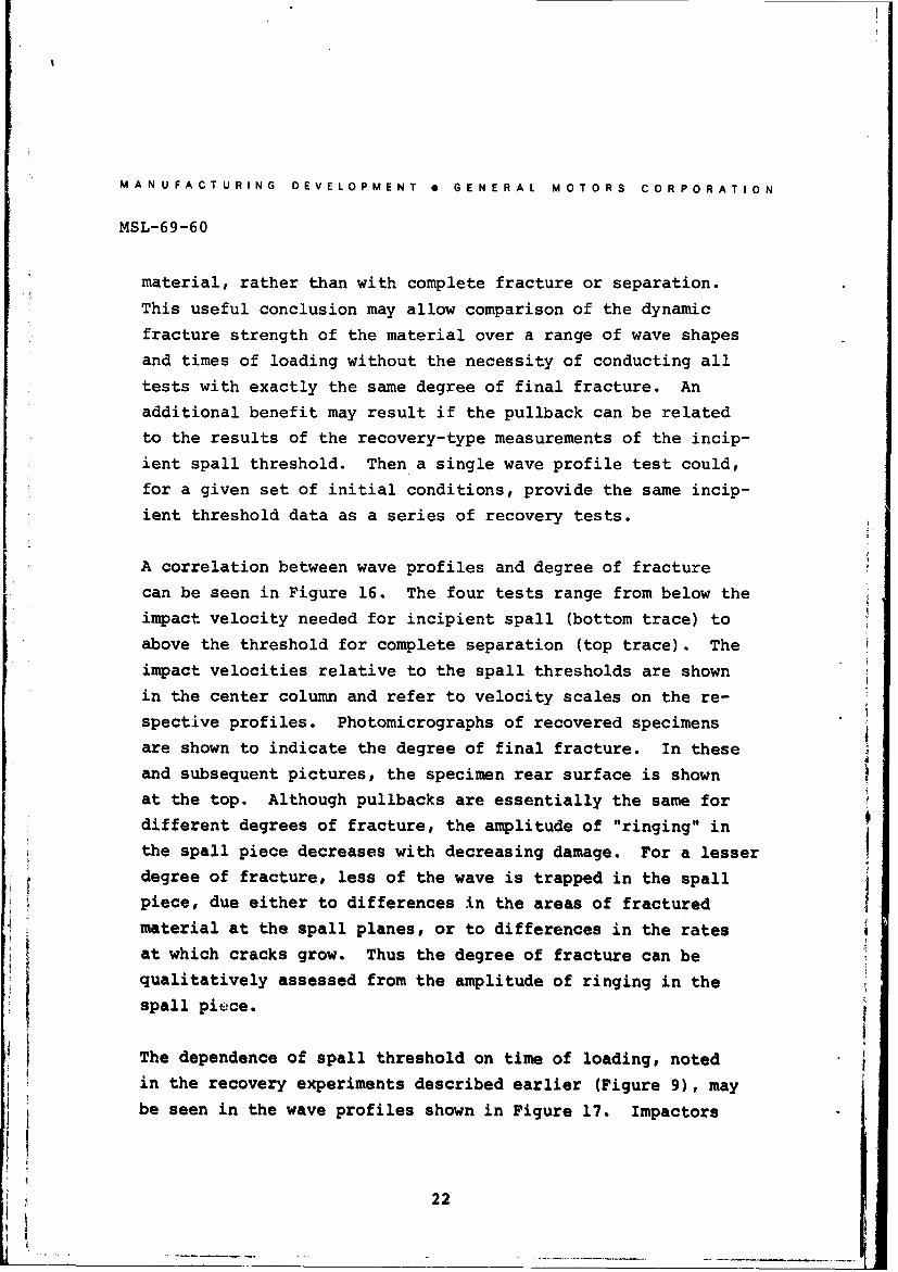
A correlation between wave profiles and degree of fracturecan be seen in Figure 16. The four tests range from below theimpact velocity needed for incipient spall (bottom trace) to
above the threshold for complete separation (top trace). The
impact velocities relative to the spall thresholds are shown
in the center column and refer to velocity scales on the re-
spective profiles. Photomicrographs of recovered specimensare shown to indicate the degree of final fracture. In these
and subsequent pictures, the specimen rear surface is shown
at the top. Although pullbacks are essentially the same for
different degrees of fracture, the amplitude of "ringing" in
the spall piece decreases with decreasing damage. For a lesserdegree of fracture, less of the wave is trapped in the spall
piece, due either to differences in the areas of fractured
material at the spall planes, or to differences in the rates
at which cracks grow. Thus the degree of fracture can be
qualitatively assessed from the amplitude of ringing in the
spall pierce.
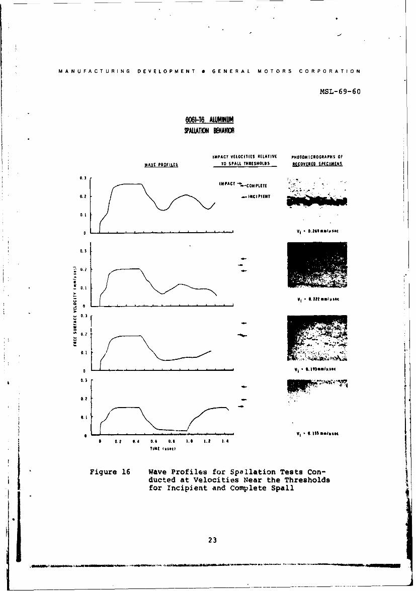
The dependence of spall threshold on time of loading, noted
in the recovery experiments described earlier (Figure 9), may
be seen in the wave profiles shown in Figure 17. Impactors
22
MANUFACTURING DEVELOPMENT 0 GENERAL MOTORS CORPORATION
MSL-69-60
6061-T6 ALUMINUMSPAIATION B81AVIOR
IMPACT VELOCITIES RELATIVE PHOTOMICROGRAPHS OF
WAVE PROFILES TO SPALL THRESHOLDS RECOVERED SPECIMENS
IMPACT "-4- COM PLETE
0.2 .- INCIPIENT 1
0.1
0~V •. O.9 101010sec
0.3
0.1
- 0.1
0 1.I$soos0.................. ............................ VI .I$| moiiIec
0.0 0,4 0.6 0.1 1.4 1,| 1 -4
TIM( twoec
Figure 16 Wave Profiles for Spallation Tests Con-ducted at Velocities Near the Thresholds ,for Incipient and Complete Spall
23
I . . J ... . ..
MANUFACTURING DEVELOPMENT 0 GENERAL MOTORS CORPORATION
MSL-69-69
0.70 ' I ' I ' I ' I ' I ' I I ' I" I
0. . .0
J1 .27mu
0.60 W-
L 020
(100 0.20 0 00 0) 1.00 1.20 1.10 L.,o
TIME IN MICROSECONDS
Figure 17 Spall Profiles at Two Times of Loading
0.5 mm and 1.9 mm thick were fired at targets twice as thickat velocities above the threshold for complete spall. Thepullback on the test with a shorter time of loading is 18%
greater than for the longer time, and corresponds to a maxi-
mum tensile stress of 14 kbars.
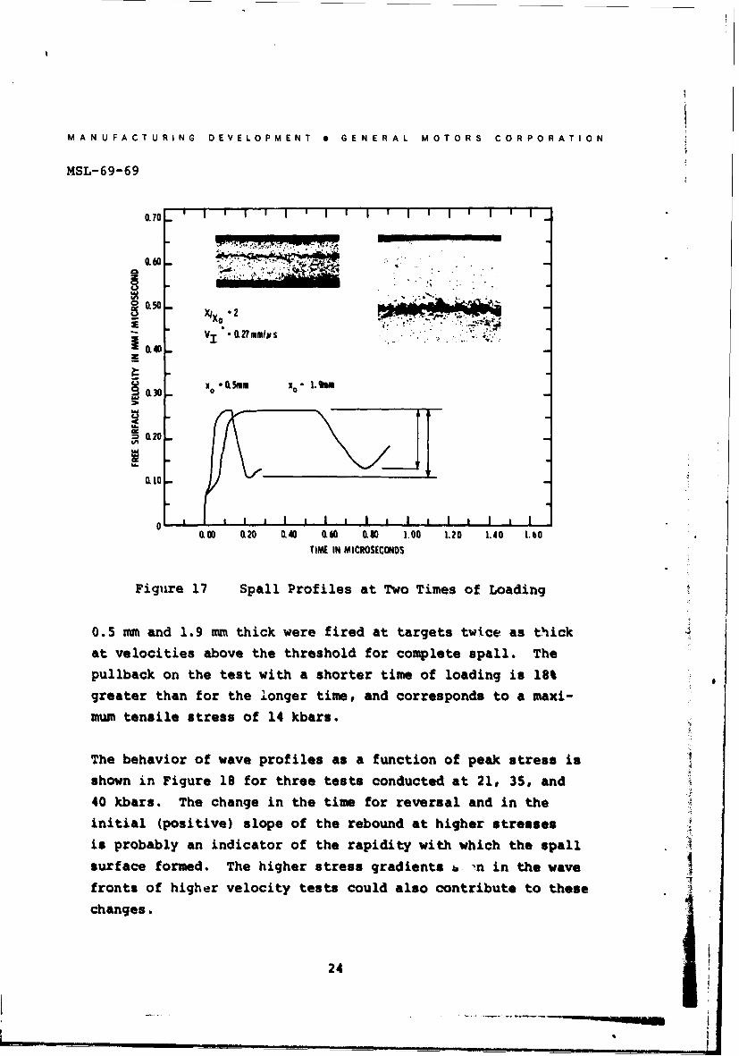
The behavior of wave profiles as a function of peak stress is
shown in Figure 18 for three tests conducted at 21, 35# and40 kbars. The change in the time for reversal and in theinitial (positive) slope of the rebound at higher stresses
is probably an indicator of the rapidity with which the spall
surface formed. The higher stress gradients b n in the wave
fronts of higher velocity tests could also contribute to these
changes.
24
MANUFACTURING DEVELOPMENT 0 GENERAL MOTORS CORPORATION
MSL-69-60
0.70 . I ' I ' I ' I " I I ' I I I" I "' I
0.60
'I
S0.50
10.30 -
D. 020
0.10
0 1 V 11I I I I I I I I I I I I
000 O20 L40 0.60 0.30 1.00 1.20 1.40 1.60
TIME IN MICROSECONDS
Figure 18 Behavior of Spall Signal for Three ImpactStresses Above the Spall Threshold
The influence of spall plane strength was studied with a target
having an "artifical" spall plane of essentially zero strength.This zero-strength plane was actually the interface between
two target plates bonded together with a thin (<0.003 mm)
epoxy layer having a tensile strength of ,. 0.01 kbars. Therear target plate was the same thickness as the impactor, put-
ting the interface at the nominal spall plane. Referring toFigure 19, for a single wave system with negligible increase
in entropy the free surface velocity would be expected to in-
crease abruptly to the impact velocity. The momentum of the
25
S., e-.~ ~
MANUFACTURING DEVELOPMENT * GENERAL MOTORS CORPORATION
MSL-69-60
ARTIFICIAL SPAILSINGlE WAVE V
..., ..
DISTNCE TIME
V \ZERO STRENG1H
UI AVARTIFICIAL SPA
DOUBL SAV Y
DIosVCE TiE
Figure 19 Predicted Wave Profiles from Specimenwith Artifical Spall Surface
a
impactor is simply transferred to the spall piece. For atwo-wave system, the momentum transfer will again take place.
However, the interactions at the interface are row more com-
plicated and a net tensile stress may develop in the spall
piece. The pullback at the rear surface shows evidence of
this tensile pulse. Figure 20 shows the measured wave profile
for such a test. The ringing in the spall piece continues for
many microseconds. The damped pullback apparently will decrease
to zero amplitude and the piece will continue with approximately
impact velocity.
26
MANUFACTURING DEVELOPMENT 0 GENERAL MOTORS CORPORATION
MSL-69-60
X0 .6m s -X - 3.W1mm
V, - Uffimmluas
OL 30
0,20
0.10
0 0.50 1.00 1.50 2.% Z50 I ,,
TIME IN MICROSECONDS
Figure 20 Measured Wave Profile for Artif..cal Spall
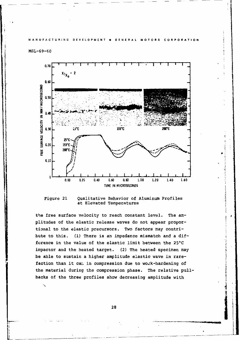
The effect of elevated temperature on nrofiles of shock waves
in 6061-TE aluminum was studied in the series of tests shown
in Figure 21. The terts were conducted using room tempera-
ture impactors to induce waves in specimens heated to the
test temperature in approximately 10 minutes. The wave pro-
files have been normalized at several places to facilities
various comparisons. In particular, the profiles have beenmade to agree at (1) the arrivals of the elastic waves, (2)the maximum free surface velocities, and (3) the arrivals of
the elastic release waves. The amplitude of the elastic pre-cursor decreases with temperature. The plastic wave velocity
decreases with increasing temperature and it takes longer for
27
MANUFACTURING DEVELOPMENT * GENERAL MOTORS CORPORATION
MSL-69-60
0.70 ' I I I I ' I I I I ' - I ' I i iXIx 2
_. I IIIIa 050 -.i .
10.40 TTZTR* -
8 . " . . ~.. t , . ' : ,,". . . . . " : . .. '
0.30 W5C 153 0C 28C
LU'25c
0 ,
0.00 0.20 0.40 0.60 (.80 1.00 1.20 1,40 1.60
TIME IN MICROSECONDS
Figure 21 Qualitative Behavior of Aluminum Profiles _4at Elevated Temperatures
the free surface velocity to reach constant level. The am-
plitudes of the elastic release waves do not appear propor-
tional to the elastic precursors. Two factors may contri-
bute to this. (1) There is an impedance mismatch and a dif-
forence in the value of the elastic limit between the 25*C
impactor and the heated target. (2) The heated specimen may
be able to sustain a higher amplitude elastic wave in rare-
faction than it ca. in compression due to wo:k-hardening of
the material during the compression phase. The relative pull-
backs of the three profiles show decreasing amplitude with
28
MAN U FACTUR;NG DEVELOPMENT a GENERAL MOTORS CORPORATION
MSL-69-60
increasing temperature. Applying Equation 1, where p and C
are now functions of temperature, the maximum tonsile stress
at the spall plane decreases from 12 kbars at 250C to 8 kbars
at 288*C.
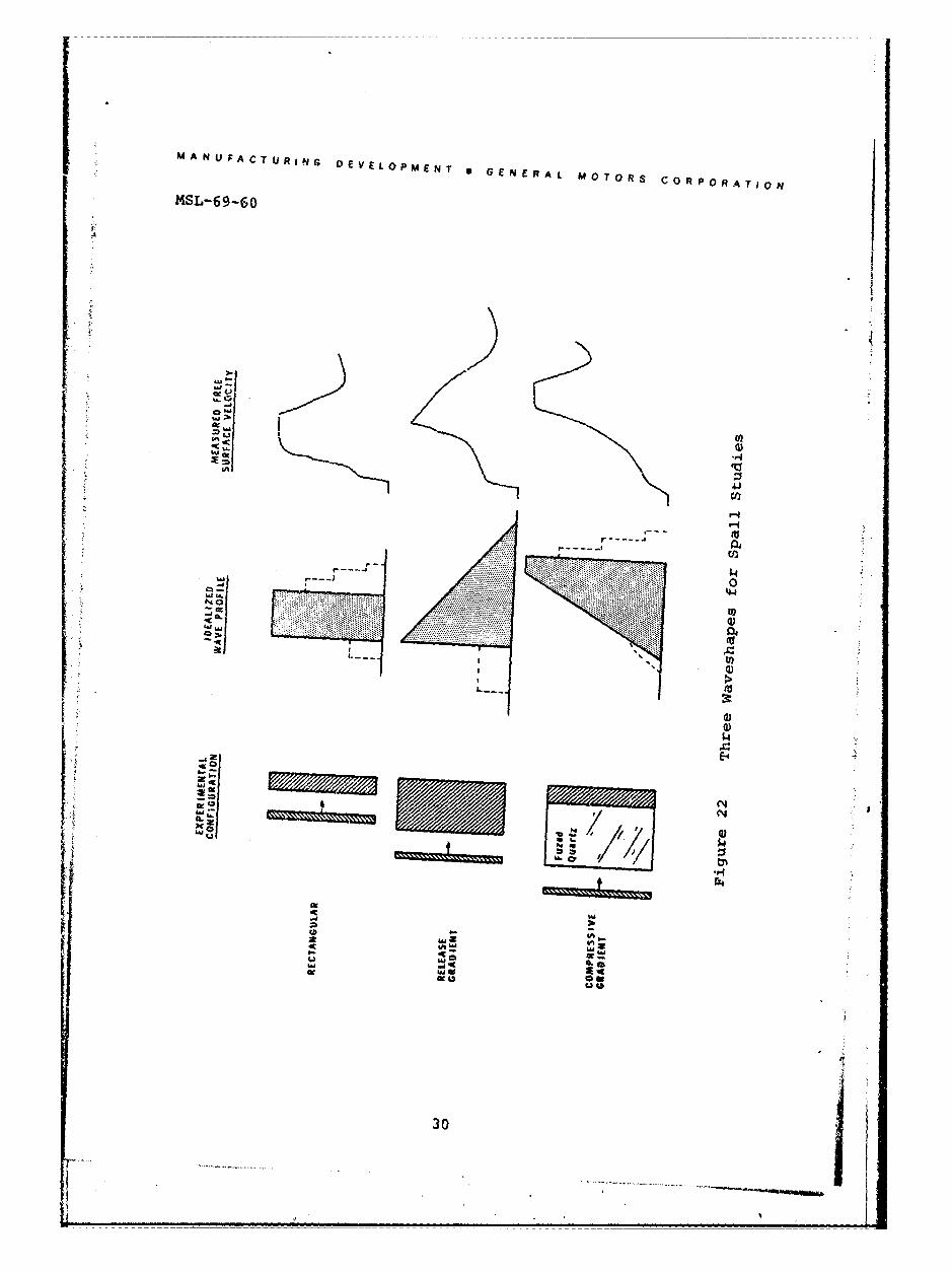
The most common use of the flat plate technique utilizes tar-
get/impactor thickness ratios of two to four and gives quasi-
rectangular stress pulses at the spall plane. This approach
permits determination of spail fracture characteristics for
well-defined stress pulses but does not provide a very strin-
gent check on models of spall fracture or computer codes de-
veloped to predict wave propagation and fracture. The ability
to adjust the shape of the shock wave causing spallation is
useful in evaluating different models and codes. Three wave-
forms of substantially different shapes that can be generated
with flat plate techniques are shown in Figure 22. (1) The
rectangular waveshape is characterized by relatively steep
compressive and release portions, with a steady-state plateau
of time duration determined primarily by the impactor thick-
ness. (2) The release gradient waveshape is achieved for
large propagation distances where the release wave has over-
taken and partially attenuated the shock front, giving a
cteep compressive portion with a more gradual release and
essentially no steady-state plateau. (3) The compressive
gradient waveshape is obtained by using a fused quartz buffer
plate between the impactor and the target, giving a gradual
compressive gradient followed by steep release. This unusual
behavior is a result of the concave downward shape of the fused
quartz hugoniot in the stress-particle velocity plane (<30 kbars),
which tends to spread the compressive wave, while the release
wave has a tendency to shock-up.
29
MANU FACT URING DEVELOPMENT * G N R L M T R O P R TO
MSL-69-60
a
)
N 0 -g
$4J
IL
w4
30)
L.1.
MANUFACTURING DEVELOPMENT 0 GENERAL MOTORS CORPORATION
MSL-69-60
SUMMARY
Spall fracture in 6061-T6 aluminum as a result of shock wave
loading is of a ductile nature, characterized by the coale-
scence of voids to form elongated cracks in and about the
nominal spall plane. The complex, time-dependent fracture
process occuring at the spall plane is communicated to the
rear surface of the specimen and affects the velocity-time
history of the surface. Measurements of the wave profile
at this surface can be utilized to furnish quantitative data
on the fracture developing within the specimen. An estimate
of the maximum stress at the spall plane can be obtained
from the simple relation, at = pC(AV/2) where I is thes pullback" in rear surface velocity due to spall fracture.
For the conditions studied, the rear surface pullback was
found to be influenced by pulse shape and material tempera-
ture, but relatively insensitive to initial impact stress or
degree of final fracture. Examination of the rear surface
velocity-time profile may also provide data on the time de-
adence of fracture and on wave damping characteristics.
Analysis is complicated, however, by such factors as uncer-
tainty in the negative stress equation of state, incomplete
understanding of the spall fracture mechanisms, and three-
dimensional effects in the vicinity of the spall fractures.
Various experimental techniques can be used to adjust wave
forms and corresponding stress gradients, permitting a more
stringent evaluation of models and computer codes used to
predict wave propagation and dynamic fracture.
31
31
MANUFACTURING DEVELOPMENT 0 GENERAL MOTORS CORPORATION
MSL-69-60
REFERENCES
1. "Materials Data Handbook, Aluminum Alloy 6061", NASAOffice of Technology Utilization, TSP 69-10065, 1969(PB 183426).
2. Munson, D. E. and Barker, L. M., "Dynamically DeterminedPressure-Volume Relationships for Aluminum, Copper, andLead", J. Appl. Phys., Vol. 37, 15 March, 1966, pp. 1652-1660.
3. Anderson, 0. L., "The Use of Ultrasonic MeasurementsUnder Modest Pressure to Estimate Compression at HighPressure", J. Phys. Chem. Solids, Vol. 27, 1966, pp. 547-565.
4. Babcock, S. G., Kumar, A., and Green, S. J., "Response ofMaterials to Suddenly Applied Stress Load", GM Defense Re-search Laboratories, Santa Barbara, California, AFFDL-TR-67-35, Part I, April, 1967.
5. Tuler, F. R., "Fracture Surface Observations in 6061-T6Aluminum at Different Strain Rates", Sandia Laboratories,Albuquerque, New Mexico, SC-DR-68-497, October, 1968.
6. Beacham, C. D., "An Electron Fractographic Study of theInfluence of Plastic Strain Conditions Upon Ductile Rup-ture Processes in Metals", ASM Trans., Vol. 56, Sept., 1963,pp. 318-326.
7. Karnes, C. H., "The Plate Impact Configuration for Deter-mining Mechanical Properties of Materials at High StrainRates", Mechanical Behavior of Materials Under DynamicLoads, Springer-Verlag New York Inc., 1968, pp. 270-293.
8. Preonas, D. D., "AFML Electrical Plate Slap Facility",Air Force Materials Laboratory, Wright-Patterson AFB,Ohio, AFML-TR-68-352, November, 1968, (AD 685 189).
9. Breed, B. R., Mader, C. L., and Venable, D., "Techniquefor the Determination of Dynamic-Tensile-Strength Character-istics", J. Appl. Phys., Vol. 38, No. 8, July, 1967,pp. 3271-3275.
10. Graham, R. A. and Hutchinson, R. E., "Thermoelastic StressPulses Resulting from Pulsed Electron Beams", Appl. Phys.Letters, Vol. 11, No. 2, 15 July, 1967, pp. 67-71.
32
MANUFACTURING DEVELOPMENT 0 GENERAL MOTORS CORPORATION
MSL-69-60
11. Miller, D. R., "Ductile Fracture", J. Aust. Inst. Metals,Vol. 14, No. 1, February, 1969, pp. 38-41.
12. Smith, J. H., "Three Low-Pressure Spall Thresholds inCopper", Dynamic Behavior of Materials, American Societyfor Testing Materials, Philadelphia, 1963, pp. 264-282.
13. Butcher, B. M., Barker, L. M., Munson, D. E., and Lunder-gan, C. D., "Influence of Stress History on Time-DependentSpalls in Metals", AIAA J., Vol. 2, No. 6, June, 1964,pp. 977-990.
14. Oscarson, J. H. and Graff, K. F., "Spall Fracture andDynamic Response of Materials", Battelle Memorial Institute,Columbus, Ohio, BAT-197A-4-3, 21 March, 1968 (AD 669 440).
15. Thurston, R. S. and Mudd, W. L., "Spallation Criteria forNumberical Calculations", Los Alamos Scientific Laboratory,New Mexico, LA-4013, Sept., 1968.
16. Tuler, F. R. and Butcher, B. M., "A Criterion for the TimeDependence of Dynamic Fracture", Int. J. Fracture Mechanics,Vol. 4, No. 4, December, 1968, pp. 431-437.
17. Taylor, J. W., "Stress Wave Profiles in Several Metals",Dislocation Dynamics, McGraw-Hill, New York, 1968, pp. 573-589.
18. Barker, L. M., "Fine Structure of Compressive and ReleaseWave Shapes in Aluminum Measured by the Velocity Inter-ferometer Technique", Behavior of Dense Media Under HighDynamic Pressures, Gordon and Breach, New York, 1968,pp. 483-505.
19. Mader, C., Los Alamos Scientific Laboratory, PrivateCommunication.
33
1
UNCLASSIFIEDSecurity Classification
DOCUMENT CONTO DATA -R &(Security Classification of title, body of abstract an'd In dexing annotation must be entered when the overall report Is classified)
I. ORIGIATING ACTIVITY (Corporate auth Manufacturing Dev. , IS. REPORT SECURITY CLASSIFICATION
GeerlMotors Corporation, G. M. TechnicalI UNCLASSIFIED
Center, Warren, Michigan 48090
3. REPORT TITLE
SHOCK PROPAGATION AND FRACTURE IN 6061-T6 ALUMINUMFROM WAVE PROFILE MEASUREMENTS
4. DESCRIPTIVE NOTES (rype of report and inclusive dates)
Interim Technical ReportS. AUT.IOR(S) (First name, middle initial, la name)
William M. Isbell, Douglas R. Christman
6. REPORT DATE 7a. TOTAL NO. OF PAGES 17b. NO. OF REFS
1970, April 38 19Sa. CONTRACT OR GRANT NO. 9a. ORIGINATOR'S REPORT NUMBER(S)
DASA-01-68-C-0114 Manufacturing Developmentb. PROJECT NO. NWER Subtask AA 106 General Motors Corporation
Report MSL-69-60C. Work Unit 097 (b. OTHER REPORT NO(S) (Any other numbers that may be assigned
this report)
d. DASA 241910. DISTRIBUTION STATEMENT
This document has been Approved for Public Releaseand Sale: Its Distribution is Unlimited.
II. SUPPLEMENTARY NOTES 12. SPONSORING MILITARY ACTIVITY
DirectorDefense Atomic Support Agency
ARWashington, D. C. 2030513. ABSTRAC T
The use of high-resolution, time-resolved measurements ofrear surface velocity in shock loaded 6061-T6 aluminum isdiscussed as a means of studying spall fracture. The in-fluence of stress pulse shape, material temperature, maxi-mum compressive stress and degree of fracture on free sur-face motion is presented and correlated with maximum tensilestress at the spall plane. A summary of dynamic propertiesdata (equation of state, elastic wave velocity, stress-strain-strair rate behavior, spall threshold) and a brief discussionon fracture in metals are also given.
DD ,NO, 61473 39 UNCLASSIFIEDSecurity CllgshIjcf tjnn
Related Documents


![Ceramic coating [tio2 zro2] on aluminium 6061 t6 for anti](https://static.cupdf.com/doc/110x72/556da50cd8b42a875d8b4901/ceramic-coating-tio2-zro2-on-aluminium-6061-t6-for-anti.jpg)