744 IEEE TRANSACTIONS ON CIRCUITS AND SYSTEMS FOR VIDEO TECHNOLOGY, VOL. 10, NO. 5, AUGUST 2000 Shape Coding Using Temporal Correlation and Joint VLC Optimization Gerry Melnikov, Guido M. Schuster, Member, IEEE, and Aggelos K. Katsaggelos, Fellow, IEEE Abstract—This paper investigates ways to explore the between frame correlation of shape information within the framework of an operationally rate-distortion (ORD) optimized coder. Contours are approximated both by connected second-order spline segments, each defined by three consecutive control points, and by segments of the motion-compensated reference contours. Consecutive con- trol points are then encoded predictively using angle and run tem- poral contexts or by tracking the reference contour. We utilize a novel criterion for selecting global object motion vectors, which im- proves efficiency. The problem is formulated as Lagrangian min- imization and solved using dynamic programming. Furthermore, we employ an iterative technique to remove dependency on a par- ticular variable length code and jointly arrive at the ORD globally optimal solution and an optimized conditional parameter distribu- tion. Index Terms—Global motion, inter-mode, Lagrangian optimiza- tion, rate-distortion optimality, shape coding, spline segment, tem- poral context, temporal correlation, VLC optimization. I. INTRODUCTION T HE object-oriented treatment of video data has regained its popularity with the advent of new multimedia appli- cations. Such applications include content-based storage and retrieval, mobile communications, and film authoring. Within the object-oriented framework, a video sequence is represented through the evolution of video object planes (VOP), with each frame composed of one or more VOP. Evolution of these VOP’s in time is described in terms of shape, texture, and motion in- formation. Treating these three components separately carries many potential benefits. For example, explicit availability of shape information is particularly important in recognition ap- plications [1]. The optimal allocation of the available resources within these three components is a key fundamental problem addressed by the operational rate distortion theory (ORD). The shape component, particularly in very low bit-rate applications, requires high efficiency of representation, since it takes up a sig- nificant percentage of the bit budget. In MPEG-4 [2], the task of encoding the shape information is completely decoupled from those of motion estimation, texture coding, and boundary esti- mation (segmentation) [3]. This is also the approach taken here, that is, we assume that the input to the proposed shape coder is Manuscript received December 15, 1998; revised January 26, 2000. This paper was recommended by Associate Editor R. Koenen. G. Melnikov and A. K. Katsaggelos are with the Department of Electrical and Computer Engineering, Northwestern University, McCormick School of Engineering and Applied Science, Evanston, IL 60208-3118 USA (e-mail: [email protected]; [email protected]). G. M. Schuster is with the 3COM, Carrier Systems Business Unit, Advanced Technologies Research Center, Mount Prospect, IL 60056-2293 USA (e-mail: [email protected]). Publisher Item Identifier S 1051-8215(00)06562-9. a binary mask defining the objects in every frame. Contours are extracted from the binary masks with the algorithm described in [4]. In the process of evaluating competing techniques for the MPEG-4 standard, several binary shape coders were considered. Bitmap-based coders [5], [6], used in the fax standards [7], [8] encode for each pixel, whether it belongs to the object or not. Contour-based coders [9]–[11], of which chain coders [12], [13] are a subset, encode the object by tracing its outline. For lossy compression, however, the coders proposed for MPEG-4 lack optimality in both their intramodes and intermodes of opera- tion. The context-based arithmetic encoder (CAE) [5] capital- izes on temporal redundancy by performing block-based mo- tion compensation and extending the context template into the neighboring pixels of the reference frame. Similarly, the MMR intercoder [6] differs from its intramode counterpart, which is derived from the fax G4 standard [7], in the choice of pixels serving as context. In the baseline and the vertex-based poly- nomial approaches (intermode) [14], [11], a contour in the cur- rent frame is approximated through motion compensation by a contour in the previous frame, with segments exceeding a cer- tain error threshold coded in their respective intramode. When it comes to rate-distortion efficiency, all of these coders are ad hoc in the intramode and, therefore, also in the intermode. Though computationally relatively inexpensive, they fail to achieve op- erational optimality, since they neither take the tradeoff between the rate and the distortion into account nor do they [5], [6], [14], [11] use the distortion metric used for their evaluation in the en- coding process. Although the four methods proposed in [5], [6], [14], and [11] achieve good compression in the intramode, poor coding efficiency in the intermode remains their major weak- ness. We have previously proposed optimal approximations of a given boundary based on curves of different orders and for var- ious distortion metrics, processing each frame independently (intramode) [15]. In [16], this problem was solved optimally and jointly with the variable-length code selection. In this work, we extend this ORD optimal framework to take into account the temporal contour redundancies present in typical video sequences. We employ a novel criterion for global object-based motion-vector selection which fits naturally into the chosen code structure. We adaptively switch between context and tracking modes to better capitalize on temporal redundancies. In addition to arriving at the intermode ORD optimal repre- sentation of a sequence for a particular coding framework, char- acterized by fixed VLC tables, we employ an iterative proce- dure to find the underlying parameter probability distribution resulting in the locally most efficient ORD curve. 1051–8215/00$10.00 © 2000 IEEE

Welcome message from author
This document is posted to help you gain knowledge. Please leave a comment to let me know what you think about it! Share it to your friends and learn new things together.
Transcript
744 IEEE TRANSACTIONS ON CIRCUITS AND SYSTEMS FOR VIDEO TECHNOLOGY, VOL. 10, NO. 5, AUGUST 2000
Shape Coding Using Temporal Correlation and JointVLC Optimization
Gerry Melnikov, Guido M. Schuster, Member, IEEE, and Aggelos K. Katsaggelos, Fellow, IEEE
Abstract—This paper investigates ways to explore the betweenframe correlation of shape information within the framework of anoperationally rate-distortion (ORD) optimized coder. Contours areapproximated both by connected second-order spline segments,each defined by three consecutive control points, and by segmentsof the motion-compensated reference contours. Consecutive con-trol points are then encoded predictively using angle and run tem-poral contexts or by tracking the reference contour. We utilize anovel criterion for selecting global object motion vectors, which im-proves efficiency. The problem is formulated as Lagrangian min-imization and solved using dynamic programming. Furthermore,we employ an iterative technique to remove dependency on a par-ticular variable length code and jointly arrive at the ORD globallyoptimal solution and an optimized conditional parameter distribu-tion.
Index Terms—Global motion, inter-mode, Lagrangian optimiza-tion, rate-distortion optimality, shape coding, spline segment, tem-poral context, temporal correlation, VLC optimization.
I. INTRODUCTION
T HE object-oriented treatment of video data has regainedits popularity with the advent of new multimedia appli-
cations. Such applications include content-based storage andretrieval, mobile communications, and film authoring. Withinthe object-oriented framework, a video sequence is representedthrough the evolution of video object planes (VOP), with eachframe composed of one or more VOP. Evolution of these VOP’sin time is described in terms of shape, texture, and motion in-formation. Treating these three components separately carriesmany potential benefits. For example, explicit availability ofshape information is particularly important in recognition ap-plications [1]. The optimal allocation of the available resourceswithin these three components is a key fundamental problemaddressed by the operational rate distortion theory (ORD). Theshape component, particularly in very low bit-rate applications,requires high efficiency of representation, since it takes up a sig-nificant percentage of the bit budget. In MPEG-4 [2], the task ofencoding the shape information is completely decoupled fromthose of motion estimation, texture coding, and boundary esti-mation (segmentation) [3]. This is also the approach taken here,that is, we assume that the input to the proposed shape coder is
Manuscript received December 15, 1998; revised January 26, 2000. Thispaper was recommended by Associate Editor R. Koenen.
G. Melnikov and A. K. Katsaggelos are with the Department of Electricaland Computer Engineering, Northwestern University, McCormick School ofEngineering and Applied Science, Evanston, IL 60208-3118 USA (e-mail:[email protected]; [email protected]).
G. M. Schuster is with the 3COM, Carrier Systems Business Unit, AdvancedTechnologies Research Center, Mount Prospect, IL 60056-2293 USA (e-mail:[email protected]).
Publisher Item Identifier S 1051-8215(00)06562-9.
a binary mask defining the objects in every frame. Contours areextracted from the binary masks with the algorithm described in[4].
In the process of evaluating competing techniques for theMPEG-4 standard, several binary shape coders were considered.Bitmap-based coders [5], [6], used in the fax standards [7], [8]encode for each pixel, whether it belongs to the object or not.Contour-based coders [9]–[11], of which chain coders [12], [13]are a subset, encode the object by tracing its outline. For lossycompression, however, the coders proposed for MPEG-4 lackoptimality in both their intramodes and intermodes of opera-tion. The context-based arithmetic encoder (CAE) [5] capital-izes on temporal redundancy by performing block-based mo-tion compensation and extending the context template into theneighboring pixels of the reference frame. Similarly, the MMRintercoder [6] differs from its intramode counterpart, which isderived from the fax G4 standard [7], in the choice of pixelsserving as context. In the baseline and the vertex-based poly-nomial approaches (intermode) [14], [11], a contour in the cur-rent frame is approximated through motion compensation by acontour in the previous frame, with segments exceeding a cer-tain error threshold coded in their respective intramode. When itcomes to rate-distortion efficiency, all of these coders aread hocin the intramode and, therefore, also in the intermode. Thoughcomputationally relatively inexpensive, they fail to achieve op-erational optimality, since they neither take the tradeoff betweenthe rate and the distortion into account nor do they [5], [6], [14],[11] use the distortion metric used for their evaluation in the en-coding process. Although the four methods proposed in [5], [6],[14], and [11] achieve good compression in the intramode, poorcoding efficiency in the intermode remains their major weak-ness.
We have previously proposed optimal approximations of agiven boundary based on curves of different orders and for var-ious distortion metrics, processing each frame independently(intramode) [15]. In [16], this problem was solved optimallyand jointly with the variable-length code selection. In this work,we extend this ORD optimal framework to take into accountthe temporal contour redundancies present in typical videosequences. We employ a novel criterion for global object-basedmotion-vector selection which fits naturally into the chosencode structure. We adaptively switch between context andtracking modes to better capitalize on temporal redundancies.
In addition to arriving at the intermode ORD optimal repre-sentation of a sequence for a particular coding framework, char-acterized by fixed VLC tables, we employ an iterative proce-dure to find the underlying parameter probability distributionresulting in the locally most efficient ORD curve.
1051–8215/00$10.00 © 2000 IEEE
MELNIKOV et al.: SHAPE CODING USING TEMPORAL CORRELATION AND JOINT VLC OPTIMIZATION 745
This paper is organized as follows. The algorithm structureis presented in Section II. The framework for taking advantageof frame to frame correlation between contours is addressedin Section III. Section IV-A deals with the context-basedcontrol-point encoding scheme, while the additive distortionmetric is discussed in Section IV-B. Section V describes howthe problem can be formulated as a shortest-path problem, andSection VI discusses VLC optimization issues. Finally, resultsare presented and discussed in Section VII.
II. THE BOUNDARY-ENCODING PROBLEM
In this paper, we solve the problem of encoding temporallycorrelated contours optimally in the ORD sense within thechosen vertex-based framework. Contours, also referred to asobjects, are approximated by connected second-order B-splinesegments, each defined by three consecutive control points
, with two neighboring splines sharing twocontrol points. Thus, an ordered set of control points constitutesa code for a (lossy) shape approximation. A second-orderB-spline , henceforth referred to simply as aspline, isa parametric curve (parameterized by) that starts at themidpoint, also called a knot, between and which endsat the midpoint between and as sweeps from zero toone. Mathematically, it is defined as follows:
(1)
where and are the and coordinates of. A sequence of second-order B-splines solves
the interpolation problem at the knots, while being differen-tiable everywhere, including the knots. This smoothness prop-erty, coupled with the simplicity of definition, makes B-splinesa natural choice for the shape-coding application. Note that, inprinciple, we can force a spline to approximate a straight lineby merging two neighboring control points. However, bound-aries consisting primarily of straight line segments are best rep-resented with straight lines, as opposed to splines, since thenthe overhead associated with transmitting double control pointsis avoided. The problem of optimal placement of a constrainednumber of spline control points in order to approximate a givenboundary was addressed in [17]. That approach, however, didnot take into account the bit rate, i.e., the cost associated withtheir encoding.
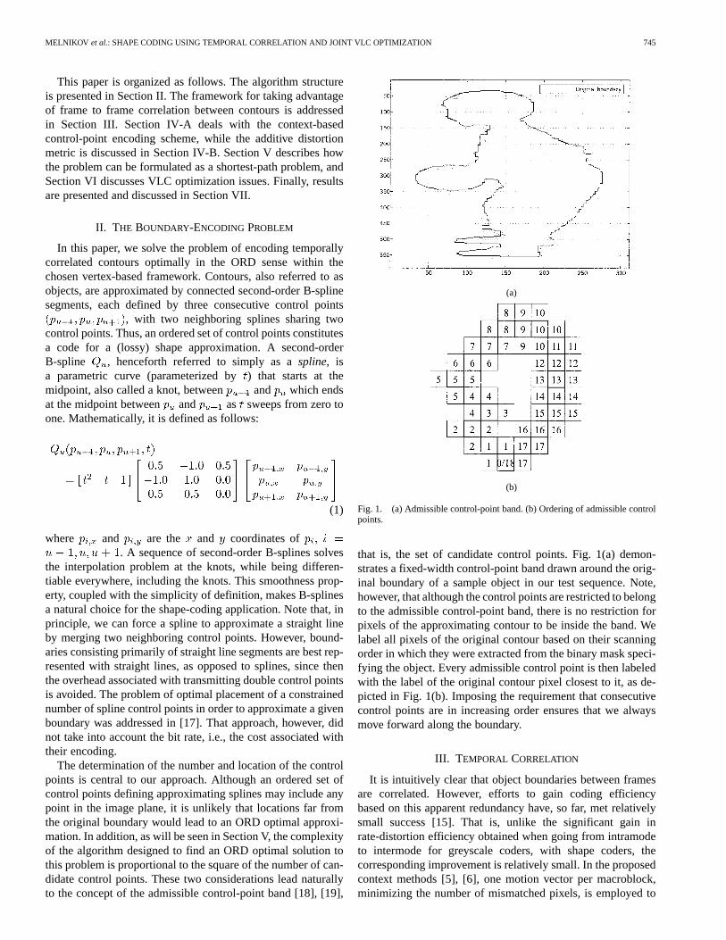
The determination of the number and location of the controlpoints is central to our approach. Although an ordered set ofcontrol points defining approximating splines may include anypoint in the image plane, it is unlikely that locations far fromthe original boundary would lead to an ORD optimal approxi-mation. In addition, as will be seen in Section V, the complexityof the algorithm designed to find an ORD optimal solution tothis problem is proportional to the square of the number of can-didate control points. These two considerations lead naturallyto the concept of the admissible control-point band [18], [19],
(a)
(b)
Fig. 1. (a) Admissible control-point band. (b) Ordering of admissible controlpoints.
that is, the set of candidate control points. Fig. 1(a) demon-strates a fixed-width control-point band drawn around the orig-inal boundary of a sample object in our test sequence. Note,however, that although the control points are restricted to belongto the admissible control-point band, there is no restriction forpixels of the approximating contour to be inside the band. Welabel all pixels of the original contour based on their scanningorder in which they were extracted from the binary mask speci-fying the object. Every admissible control point is then labeledwith the label of the original contour pixel closest to it, as de-picted in Fig. 1(b). Imposing the requirement that consecutivecontrol points are in increasing order ensures that we alwaysmove forward along the boundary.
III. T EMPORAL CORRELATION
It is intuitively clear that object boundaries between framesare correlated. However, efforts to gain coding efficiencybased on this apparent redundancy have, so far, met relativelysmall success [15]. That is, unlike the significant gain inrate-distortion efficiency obtained when going from intramodeto intermode for greyscale coders, with shape coders, thecorresponding improvement is relatively small. In the proposedcontext methods [5], [6], one motion vector per macroblock,minimizing the number of mismatched pixels, is employed to
746 IEEE TRANSACTIONS ON CIRCUITS AND SYSTEMS FOR VIDEO TECHNOLOGY, VOL. 10, NO. 5, AUGUST 2000
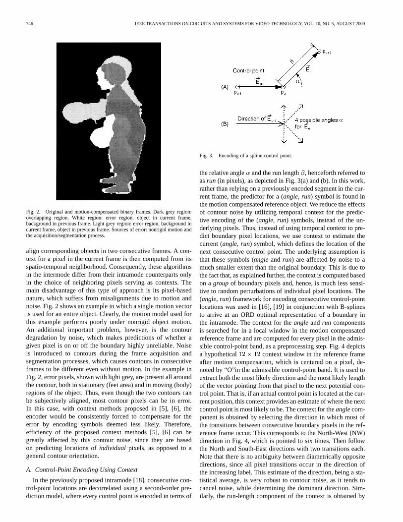
Fig. 2. Original and motion-compensated binary frames. Dark grey region:overlapping region. White region: error region, object in current frame,background in previous frame. Light grey region: error region, background incurrent frame, object in previous frame. Sources of error: nonrigid motion andthe acquisition/segmentation process.
align corresponding objects in two consecutive frames. A con-text for a pixel in the current frame is then computed from itsspatio-temporal neighborhood. Consequently, these algorithmsin the intermode differ from their intramode counterparts onlyin the choice of neighboring pixels serving as contexts. Themain disadvantage of this type of approach is its pixel-basednature, which suffers from misalignments due to motion andnoise. Fig. 2 shows an example in which a single motion vectoris used for an entire object. Clearly, the motion model used forthis example performs poorly under nonrigid object motion.An additional important problem, however, is the contourdegradation by noise, which makes predictions of whether agiven pixel is on or off the boundary highly unreliable. Noiseis introduced to contours during the frame acquisition andsegmentation processes, which causes contours in consecutiveframes to be different even without motion. In the example inFig. 2, error pixels, shown with light grey, are present all aroundthe contour, both in stationary (feet area) and in moving (body)regions of the object. Thus, even though the two contours canbe subjectively aligned, most contour pixels can be in error.In this case, with context methods proposed in [5], [6], theencoder would be consistently forced to compensate for theerror by encoding symbols deemed less likely. Therefore,efficiency of the proposed context methods [5], [6] can begreatly affected by this contour noise, since they are basedon predicting locations ofindividual pixels, as opposed to ageneral contour orientation.
A. Control-Point Encoding Using Context
In the previously proposed intramode [18], consecutive con-trol-point locations are decorrelated using a second-order pre-diction model, where every control point is encoded in terms of
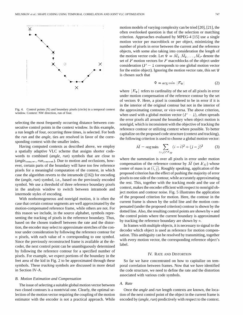
Fig. 3. Encoding of a spline control point.
the relative angle and the run length , henceforth referred toasrun (in pixels), as depicted in Fig. 3(a) and (b). In this work,rather than relying on a previously encoded segment in the cur-rent frame, the predictor for a (angle, run) symbol is found inthe motion compensated reference object. We reduce the effectsof contour noise by utilizing temporal context for the predic-tive encoding of the (angle, run) symbols, instead of the un-derlying pixels. Thus, instead of using temporal context to pre-dict boundary pixel locations, we use context to estimate thecurrent (angle, run) symbol, which defines the location of thenext consecutive control point. The underlying assumption isthat these symbols (angleand run) are affected by noise to amuch smaller extent than the original boundary. This is due tothe fact that, as explained further, the context is computed basedon agroup of boundary pixels and, hence, is much less sensi-tive to random perturbations of individual pixel locations. The(angle, run) framework for encoding consecutive control-pointlocations was used in [16], [19] in conjunction with B-splinesto arrive at an ORD optimal representation of a boundary inthe intramode. The context for theangleandrun componentsis searched for in a local window in the motion compensatedreference frame and are computed for every pixel in the admis-sible control-point band, as a preprocessing step. Fig. 4 depictsa hypothetical context window in the reference frameafter motion compensation, which is centered on a pixel, de-noted by “O”in the admissible control-point band. It is used toextract both the most likely direction and the most likely lengthof the vector pointing from that pixel to the next potential con-trol point. That is, if an actual control point is located at the cur-rent position, this context provides an estimate of where the nextcontrol point is most likely to be. The context for theanglecom-ponent is obtained by selecting the direction in which most ofthe transitions between consecutive boundary pixels in the ref-erence frame occur. This corresponds to the North-West (NW)direction in Fig. 4, which is pointed to six times. Then followthe North and South-East directions with two transitions each.Note that there is no ambiguity between diametrically oppositedirections, since all pixel transitions occur in the direction ofthe increasing label. This estimate of the direction, being a sta-tistical average, is very robust to contour noise, as it tends tocancel noise, while determining the dominant direction. Sim-ilarly, the run-length component of the context is obtained by
MELNIKOV et al.: SHAPE CODING USING TEMPORAL CORRELATION AND JOINT VLC OPTIMIZATION 747
Fig. 4. Control points (X) and boundary pixels (circle) in a temporal contextwindow. Context: NW direction, run of four.
selecting the most frequently occurring distance between con-secutive control points in the context window. In this example,a run length of four, occurring three times, is selected. For boththe run and theangle, ties are resolved in favor of the corre-sponding context with the smaller index.
Having computed contexts as described above, we employa spatially adaptive VLC scheme that assigns shorter code-words to combined (angle, run) symbols that are close to(angle , run ). Due to motion and occlusions, how-ever, certain parts of the boundary will have too few referencepixels for a meaningful computation of the context, in whichcase the algorithm reverts to the intramode ([16]) for encodingthe (angle, run) symbol, i.e., based on the previously encodedsymbol. We use a threshold of three reference boundary pixelsin the analysis window to switch between intramode andintermode styles of encoding.
With nonhomogeneous and nonrigid motion, it is often thecase that certain contour segments are well approximated by themotion-compensated reference frame, while others are not. Forthis reason we include, in the source alphabet, symbols repre-senting the tracking of pixels in the reference boundary. Thus,based on the chosen tradeoff between the rate and the distor-tion, the encoder may select to approximate stretches of the con-tour under consideration by following the reference contour for
pixels, with each value of corresponding to one symbol.Since the previously reconstructed frame is available at the de-coder, the next control point can be unambiguously determinedby following the reference contour for a specified number ofpixels. For example, we expect portions of the boundary in thefeet area of the kid in Fig. 2 to be approximated through thesesymbols. Thesetrackingsymbols are discussed in more detailin Section IV-A.
B. Motion Estimation and Compensation
The issue of selecting a suitable global motion vector betweentwo closed contours is a nontrivial one. Clearly, the optimal se-lection of the motion vector requiring the coupling of the motionestimator with the encoder is not a practical approach. While
motion models of varying complexity can be tried [20], [21], theoften overlooked question is that of the selection or matchingcriterion. Approaches evaluated by MPEG-4 [15] use a singlemotion vector per macroblock or per object, minimizing thenumber of pixels in error between the current and the referenceobjects, with some also taking into consideration the length ofthe motion vector code. Let denote theset of motion vectors for macroblocks of the object underconsideration ( corresponds to one global motion vectorfor the entire object). Ignoring the motion vector rate, this setis chosen such that
(2)
where refers to cardinality of the set of all pixels in errorunder motion compensation of the reference contour by the setof vectors . Here, a pixel is considered to be in error if it isin the interior of the original contour but not in the interior ofthe approximating contour, or vice-versa. The above criterion,when used with a global motion vector , often spreadsthe error pixels all around the boundary when object motion isnonrigid, which is inconsistent with the objective of tracking thereference contour or utilizing context where possible. To bettercapitalize on the proposed code structure (context and tracking),the following criterion is used to choose a global motion vector:
(3)
where the summation is over all pixels in error under motioncompensation of the reference contour by(set ) whosecenter of mass is at . Roughly speaking, application of theproposed criterion has the effect of pushing the majority of errorpixels to one side of the contour, while accurately approximatingthe rest. This, together with the tracking mode and the use ofcontext, makes the encoder efficient with respect to nonrigid ob-ject motion and contour noise. Fig. 5 illustrates the applicationof the proposed criterion for motion. Here, the contour in thecurrent frame is shown by the solid line and the motion com-pensated (under the proposed criterion) contour is shown by thedotted line. Also, the resulting control points are shown byandthe control points where the current boundary is approximatedby tracking the reference boundary are shown by.
In frames with multiple objects, it is necessary to signal to thedecoder which object is used as reference for motion compen-sation. This ambiguity can be resolved by transmitting, togetherwith every motion vector, the corresponding reference object’slabel.
IV. RATE AND DISTORTION
So far we have concentrated on how to capitalize on tem-poral correlation between frames. Now that we have identifiedthe code structure, we need to define the rate and the distortionassociated with various code symbols.
A. Rate
Once theangleandrun length contexts are known, the loca-tion of the next control point of the object in the current frame isencoded by (angle, run) predictively with respect to the context.
748 IEEE TRANSACTIONS ON CIRCUITS AND SYSTEMS FOR VIDEO TECHNOLOGY, VOL. 10, NO. 5, AUGUST 2000
Fig. 5. Control-point placement under very low bit-rate. Circles correspond to the tracking mode.
(a)
(b)
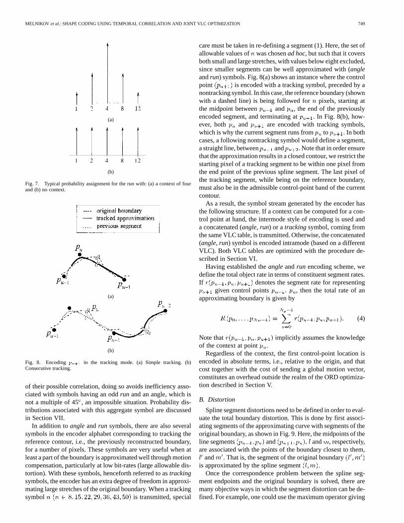
Fig. 6. Typical probability assignment for the direction with: (a) NW contextand (b) no context.
In this framework, shorter codewords are assigned to directionsand runs closest to the contexts. Fig. 6(a) shows a typical condi-tional direction probability distribution, given the NW context,which also served as the initial distribution used in the VLC op-
timization procedure, discussed in Section VI. A total of 16 dif-ferent directions are allowed, with the direction correspondingto the direction of the context having the greatest probability.Note that this distribution is conditional and distributions for theother contexts of direction are obtained by rotating the figureaccordingly. Note also that with the proposed structure of theanglecomponent, twice as many directional transitions are nowpossible than in [15], since we added the angles correspondingto a knight-like (as in chess) move ofpixels along one of theaxis and a move of along the other. In view of the VLC op-timization (Section VI), this is not, however, going to have anadverse impact on the rate.
Fig. 6(b) shows the eight equiprobable directions when a lo-cation under consideration does not have an angle context. Inthis case, the encoder reverts to the intramode style, i.e., thecurrent direction is encoded predictively from the previouslyencoded one in the same contour. Overall, the angle alphabethas 16 and eight symbols for the two situations, respectively.Similarly, an initial guess for the conditional probability distri-bution for the run length is shown in Fig. 7(a) for the case thecontext is four. Since there are five different run lengths for fivepossible contexts, a total of 25run symbols are used when therun context is present, and another five symbols are used whenit is not. In the latter case, therun is encoded absolutely. Notethat therun always refers to the maximum between the absolutedisplacements in the and directions. In both Figs. 6 and 7,vector lengths are proportional to the probability of the corre-sponding symbol. For both theangleand therun components,no contextual information is available when there too few refer-ence boundary or control points in the reference window.
The run andanglecomponents are grouped together for thepurpose of forming one symbol. In addition to taking advantage
MELNIKOV et al.: SHAPE CODING USING TEMPORAL CORRELATION AND JOINT VLC OPTIMIZATION 749
(a)
(b)
Fig. 7. Typical probability assignment for the run with: (a) a context of fourand (b) no context.
(a)
(b)
Fig. 8. Encodingp in the tracking mode. (a) Simple tracking. (b)Consecutive tracking.
of their possible correlation, doing so avoids inefficiency asso-ciated with symbols having an oddrun and an angle, which isnot a multiple of 45, an impossible situation. Probability dis-tributions associated with this aggregate symbol are discussedin Section VII.
In addition toangleandrun symbols, there are also severalsymbols in the encoder alphabet corresponding to tracking thereference contour, i.e., the previously reconstructed boundary,for a number of pixels. These symbols are very useful when atleast a part of the boundary is approximated well through motioncompensation, particularly at low bit-rates (large allowable dis-tortion). With these symbols, henceforth referred to astrackingsymbols, the encoder has an extra degree of freedom in approxi-mating large stretches of the original boundary. When a trackingsymbol is transmitted, special
care must be taken in re-defining a segment (1). Here, the set ofallowable values of was chosenad hoc, but such that it coversboth small and large stretches, with values below eight excluded,since smaller segments can be well approximated with (angleandrun) symbols. Fig. 8(a) shows an instance where the controlpoint is encoded with a tracking symbol, preceded by anontracking symbol. In this case, the reference boundary (shownwith a dashed line) is being followed for pixels, starting atthe midpoint between and , the end of the previouslyencoded segment, and terminating at . In Fig. 8(b), how-ever, both and are encoded with tracking symbols,which is why the current segment runs fromto . In bothcases, a following nontracking symbol would define a segment,a straight line, between and . Note that in order ensurethat the approximation results in a closed contour, we restrict thestarting pixel of a tracking segment to be within one pixel fromthe end point of the previous spline segment. The last pixel ofthe tracking segment, while being on the reference boundary,must also be in the admissible control-point band of the currentcontour.
As a result, the symbol stream generated by the encoder hasthe following structure. If a context can be computed for a con-trol point at hand, the intermode style of encoding is used anda concatenated (angle, run) or a trackingsymbol, coming fromthe same VLC table, is transmitted. Otherwise, the concatenated(angle, run) symbol is encoded intramode (based on a differentVLC). Both VLC tables are optimized with the procedure de-scribed in Section VI.
Having established theangleandrun encoding scheme, wedefine the total object rate in terms of constituent segment rates.If denotes the segment rate for representing
given control points , then the total rate of anapproximating boundary is given by
(4)
Note that implicitly assumes the knowledgeof the context at point .
Regardless of the context, the first control-point location isencoded in absolute terms, i.e., relative to the origin, and thatcost together with the cost of sending a global motion vector,constitutes an overhead outside the realm of the ORD optimiza-tion described in Section V.
B. Distortion
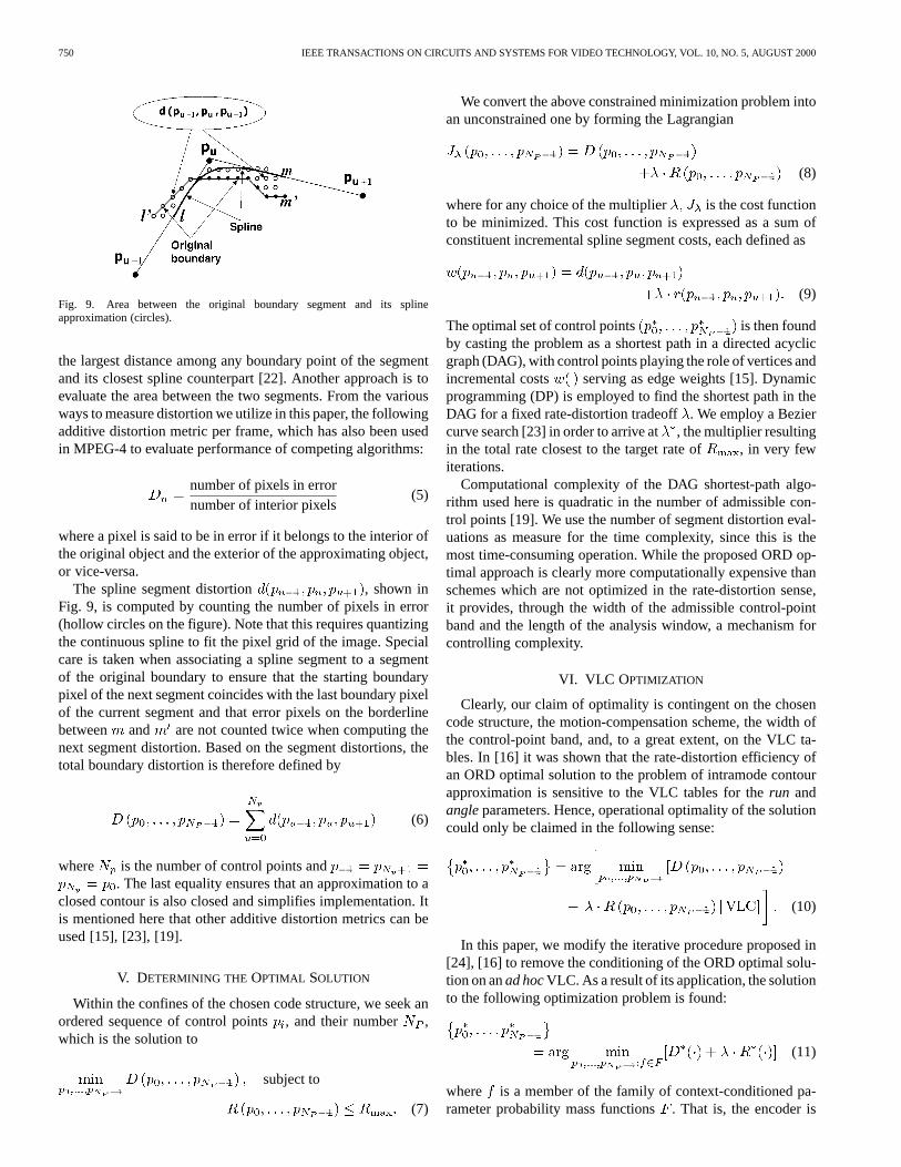
Spline segment distortions need to be defined in order to eval-uate the total boundary distortion. This is done by first associ-ating segments of the approximating curve with segments of theoriginal boundary, as shown in Fig. 9. Here, the midpoints of theline segments and and , respectively,are associated with the points of the boundary closest to them,
and . That is, the segment of the original boundaryis approximated by the spline segment .
Once the correspondence problem between the spline seg-ment endpoints and the original boundary is solved, there aremany objective ways in which the segment distortion can be de-fined. For example, one could use the maximum operator giving
750 IEEE TRANSACTIONS ON CIRCUITS AND SYSTEMS FOR VIDEO TECHNOLOGY, VOL. 10, NO. 5, AUGUST 2000
Fig. 9. Area between the original boundary segment and its splineapproximation (circles).
the largest distance among any boundary point of the segmentand its closest spline counterpart [22]. Another approach is toevaluate the area between the two segments. From the variousways to measure distortion we utilize in this paper, the followingadditive distortion metric per frame, which has also been usedin MPEG-4 to evaluate performance of competing algorithms:
number of pixels in errornumber of interior pixels
(5)
where a pixel is said to be in error if it belongs to the interior ofthe original object and the exterior of the approximating object,or vice-versa.
The spline segment distortion , shown inFig. 9, is computed by counting the number of pixels in error(hollow circles on the figure). Note that this requires quantizingthe continuous spline to fit the pixel grid of the image. Specialcare is taken when associating a spline segment to a segmentof the original boundary to ensure that the starting boundarypixel of the next segment coincides with the last boundary pixelof the current segment and that error pixels on the borderlinebetween and are not counted twice when computing thenext segment distortion. Based on the segment distortions, thetotal boundary distortion is therefore defined by
(6)
where is the number of control points and. The last equality ensures that an approximation to a
closed contour is also closed and simplifies implementation. Itis mentioned here that other additive distortion metrics can beused [15], [23], [19].
V. DETERMINING THE OPTIMAL SOLUTION
Within the confines of the chosen code structure, we seek anordered sequence of control points, and their number ,which is the solution to
subject to
(7)
We convert the above constrained minimization problem intoan unconstrained one by forming the Lagrangian
(8)
where for any choice of the multiplier is the cost functionto be minimized. This cost function is expressed as a sum ofconstituent incremental spline segment costs, each defined as
(9)
The optimal set of control points is then foundby casting the problem as a shortest path in a directed acyclicgraph (DAG), with control points playing the role of vertices andincremental costs serving as edge weights [15]. Dynamicprogramming (DP) is employed to find the shortest path in theDAG for a fixed rate-distortion tradeoff. We employ a Beziercurve search [23] in order to arrive at, the multiplier resultingin the total rate closest to the target rate of , in very fewiterations.
Computational complexity of the DAG shortest-path algo-rithm used here is quadratic in the number of admissible con-trol points [19]. We use the number of segment distortion eval-uations as measure for the time complexity, since this is themost time-consuming operation. While the proposed ORD op-timal approach is clearly more computationally expensive thanschemes which are not optimized in the rate-distortion sense,it provides, through the width of the admissible control-pointband and the length of the analysis window, a mechanism forcontrolling complexity.
VI. VLC OPTIMIZATION
Clearly, our claim of optimality is contingent on the chosencode structure, the motion-compensation scheme, the width ofthe control-point band, and, to a great extent, on the VLC ta-bles. In [16] it was shown that the rate-distortion efficiency ofan ORD optimal solution to the problem of intramode contourapproximation is sensitive to the VLC tables for therun andangleparameters. Hence, operational optimality of the solutioncould only be claimed in the following sense:
(10)
In this paper, we modify the iterative procedure proposed in[24], [16] to remove the conditioning of the ORD optimal solu-tion on anad hocVLC. As a result of its application, the solutionto the following optimization problem is found:
(11)
where is a member of the family of context-conditioned pa-rameter probability mass functions. That is, the encoder is
MELNIKOV et al.: SHAPE CODING USING TEMPORAL CORRELATION AND JOINT VLC OPTIMIZATION 751
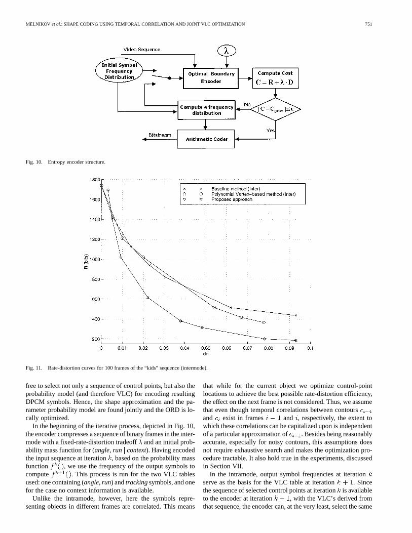
Fig. 10. Entropy encoder structure.
Fig. 11. Rate-distortion curves for 100 frames of the “kids” sequence (intermode).
free to select not only a sequence of control points, but also theprobability model (and therefore VLC) for encoding resultingDPCM symbols. Hence, the shape approximation and the pa-rameter probability model are found jointly and the ORD is lo-cally optimized.
In the beginning of the iterative process, depicted in Fig. 10,the encoder compresses a sequence of binary frames in the inter-mode with a fixed-rate-distortion tradeoffand an initial prob-ability mass function for (angle, run context). Having encodedthe input sequence at iteration, based on the probability massfunction , we use the frequency of the output symbols tocompute . This process is run for the two VLC tablesused: one containing (angle, run) andtrackingsymbols, and onefor the case no context information is available.
Unlike the intramode, however, here the symbols repre-senting objects in different frames are correlated. This means
that while for the current object we optimize control-pointlocations to achieve the best possible rate-distortion efficiency,the effect on the next frame is not considered. Thus, we assumethat even though temporal correlations between contoursand exist in frames and , respectively, the extent towhich these correlations can be capitalized upon is independentof a particular approximation of . Besides being reasonablyaccurate, especially for noisy contours, this assumptions doesnot require exhaustive search and makes the optimization pro-cedure tractable. It also hold true in the experiments, discussedin Section VII.
In the intramode, output symbol frequencies at iterationserve as the basis for the VLC table at iteration . Sincethe sequence of selected control points at iterationis availableto the encoder at iteration , with the VLC’s derived fromthat sequence, the encoder can, at the very least, select the same
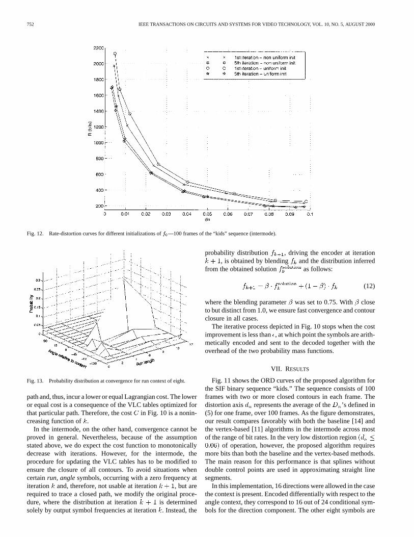
752 IEEE TRANSACTIONS ON CIRCUITS AND SYSTEMS FOR VIDEO TECHNOLOGY, VOL. 10, NO. 5, AUGUST 2000
Fig. 12. Rate-distortion curves for different initializations off —100 frames of the “kids” sequence (intermode).
Fig. 13. Probability distribution at convergence for run context of eight.
path and, thus, incur a lower or equal Lagrangian cost. The loweror equal cost is a consequence of the VLC tables optimized forthat particular path. Therefore, the costin Fig. 10 is a nonin-creasing function of .
In the intermode, on the other hand, convergence cannot beproved in general. Nevertheless, because of the assumptionstated above, we do expect the cost function to monotonicallydecrease with iterations. However, for the intermode, theprocedure for updating the VLC tables has to be modified toensure the closure of all contours. To avoid situations whencertainrun, anglesymbols, occurring with a zero frequency atiteration and, therefore, not usable at iteration , but arerequired to trace a closed path, we modify the original proce-dure, where the distribution at iteration is determinedsolely by output symbol frequencies at iteration. Instead, the
probability distribution , driving the encoder at iteration, is obtained by blending and the distribution inferred
from the obtained solution as follows:
(12)
where the blending parameterwas set to 0.75. With closeto but distinct from 1.0, we ensure fast convergence and contourclosure in all cases.
The iterative process depicted in Fig. 10 stops when the costimprovement is less than, at which point the symbols are arith-metically encoded and sent to the decoded together with theoverhead of the two probability mass functions.
VII. RESULTS
Fig. 11 shows the ORD curves of the proposed algorithm forthe SIF binary sequence “kids.” The sequence consists of 100frames with two or more closed contours in each frame. Thedistortion axis represents the average of the’s defined in(5) for one frame, over 100 frames. As the figure demonstrates,our result compares favorably with both the baseline [14] andthe vertex-based [11] algorithms in the intermode across mostof the range of bit rates. In the very low distortion region
of operation, however, the proposed algorithm requiresmore bits than both the baseline and the vertex-based methods.The main reason for this performance is that splines withoutdouble control points are used in approximating straight linesegments.
In this implementation, 16 directions were allowed in the casethe context is present. Encoded differentially with respect to theangle context, they correspond to 16 out of 24 conditional sym-bols for the direction component. The other eight symbols are
MELNIKOV et al.: SHAPE CODING USING TEMPORAL CORRELATION AND JOINT VLC OPTIMIZATION 753
used when a context is not present. The run component was rep-resented by 25 symbols, with only five symbols (correspondingto runs of 1, 2, 4, 8, and 12) used for any given context. Addi-tionally, seven symbols were used for the tracking mode, rep-resenting seven different lengths (spaced uniformly from 8 to45) for which a reference contour could be tracked. Bit rates forthe proposed method, reported in Fig. 11, take into account bitsfor the global motion vectors, searched in a window.Although “kids” is a high-motion sequence and we use a singlemotion vector per object, contexts were found for most of thecontrol points in the sequence, and hence, the intermode wasused most of the time.
Aside from Lagrangian optimization, a combination offactors is responsible for the efficiency of the proposed ap-proach. Primarily, it is the combined (angle, run) context andtracking coding framework, which minimized the effects ofcontour noise and capitalized on partially homogeneous motionof objects. As a result, symbols with higher probabilitieswere consistently selected by the encoder. The second mostimportant factor was VLC optimization, as is further discussedin this section. The proposed motion vector selection criterion(3) provided a relatively small improvement, with respect tothe criterion in (2) for the type of motion present in the testedsequence.
A. Initialization of Symbol Probabilities
The iterative scheme for optimizing the VLC’s, describedin Section VI, is locally optimized in the following sense. Let
be the parameter probability mass function, with its corre-sponding cost , at the termination of the iterative process de-picted in Fig. 10. Then , another probability massfunction separated by a small distance fromwill result in aLagrangian cost when applied to the optimal encoderunder the same rate-distortion tradeoff. Since is a localminimum, there is no guarantee that perturbations tolargerthan will not outperform it in terms of the Lagrangian cost.
To get an idea of how close a local minimum is to theglobal minimum, we conducted several experiments with dif-ferent initializations of the probability mass function. Fig. 12shows the corresponding rate-distortion curves.
Fig. 13 shows the symbol probability distribution, with theruncontext of eight, after five iterations of the process describedin Section VI. As expected, a sharp peak occurs for the run ofeight and the angle displacement of zero. This indicates thatfollowing the context in both therun and theanglewas the mostfrequently occurring symbol.
VIII. C ONCLUSION
In this work, we proposed a novel technique for capitalizingon the between frame correlation of shape information, whileachieving an ORD optimal performance. In addition, we haveremoved the dependency of the ORD optimal solution on a par-ticular VLC used to encode the generated symbols.
Although the proposed algorithm clearly outperformsexisting intermode techniques, its overall improvement inefficiency of shape representation with respect to the intramodeis not comparable to that of texture representation, where
temporal correlation is exploited to a much larger degree. Weexpect that further gains can be made by adaptively adjustingthe size of the context window with and, possibly, by usinga more sophisticated motion model (global or block-based).Also, a hybrid intra/inter technique, utilizing prediction withrespect to both the context and the previously encoded controlpoint, may outperform this approach. Since the use of contextcouples consecutive frames, the global (across objects) opti-mality is lost. Hence, an approach using different values offor the same object in different frames may potentially be moreefficient.
REFERENCES
[1] P. van Otterloo, A Contour-Oriented Approach for Shape Anal-ysis. Englewood Cliffs, NJ: Prentice-Hall, 1991.
[2] R. Koenen, “MPEG-4 multimedia for our time,”IEEE Spectrum, vol.36, pp. 26–33, Feb. 1999.
[3] G. Martinez, “Shape estimation of articulated objects for object-basedanalysis-synthesis coding (OBASC),”Signal Processing: ImageCommun., vol. 9, pp. 175–199, Mar. 1997.
[4] D. H. Ballard and C. M. Brown,Comput. Vis.. Englewood Cliffs, NJ:Prentice-Hall, 1982.
[5] N. Brady, F. Bossen, and N. Murphy, “Context-based arithmetic en-coding of 2-D shape sequences,” inProc. Int. Conf. Image Processing,1997, pp. I-29–32.
[6] N. Yamaguchi, T. Ida, and T. Watanabe, “A binary shape coding methodusing modified MMR,” inProc. Int. Conf. Image Processing, 1997, pp.I-504–508.
[7] Facsimile Coding Schemes and Coding Functions for Group 4 FacsimileApparatus, CCITT Recommendation T.6, 1994.
[8] Coded Representation of Picture and Audio Information, ProgressiveBi-Level Image Compression, ISO Draft Int. Standard 11544, 1992.
[9] P. Gerken, “Object-based analysis-synthesis coding of image sequencesat very low bit rates,”IEEE Trans. Circuits Syst. I, vol. 41, pp. 228–235,June 1994.
[10] M. Hötter, “Object-oriented analysis-synthesis coding based on movingtwo-dimensional objects,”Signal Processing: Image Commun., vol. 2,pp. 409–428, Dec. 1990.
[11] K. J. O’Connell, “Object-adaptive vertex-based shape coding method,”IEEE Trans. Circuits Syst. Video Technol., vol. 7, pp. 251–255, Feb.1997.
[12] H. Freeman, “On the encoding of arbitrary geometric configurations,”IRE Trans. Electron. Comput., vol. EC-10, pp. 260–268, June 1961.
[13] M. Eden and M. Kocher, “On the performance of contour coding algo-rithm in the context of image coding. Part I: Contour segment coding,”Signal Processing: Image Commun., vol. 8, pp. 381–386, July 1985.
[14] S. Lee, D. Cho, Y. Cho, S. Son, E. Jang, and J. Shin, “Binary shapecoding using 1-D distance values from baseline,” inProc. Int. Conf.Image Processing, 1997, pp. I-508–511.
[15] A. K. Katsaggelos, L. P. Kondi, F. W. Meier, J. Ostermann, and G. M.Schuster, “MPEG-4 and ratedistortion-based shape-coding techniques,”Proc. IEEE, vol. 86, pp. 1126–1154, June 1998.
[16] G. Melnikov, G. M. Schuster, and A. K. Katsaggelos, “Simultaneousoptimal boundary encoding and variable-length code selection,” inProc.Int. Conf. Image Processing, 1998, pp. I-256–260.
[17] A. K. Jain, Fundamentals of Digital Image Processing. EnglewoodCliffs, NJ: Prentice-Hall, 1989.
[18] G. M. Schuster and A. K. Katsaggelos, “An optimal polygonal boundaryencoding scheme in the rate distortion sense,”IEEE Transa. Image Pro-cessing, vol. 7, pp. 13–26, Jan. 1998.
[19] G. M. Schuster, G. Melnikov, and A. K. Katsaggelos, “Operationallyoptimal vertex-based shape coding,”IEEE Signal Processing Mag., pp.91–108, Nov. 1998.
[20] N. Diehl, “Object-oriented motion estimation and segmentation inimage sequences,”Signal Processing: Image Commun., vol. 3, pp.23–56, 1991.
[21] J. Ostermann, “Object-oriented analysis-synthesis coding (OOASC)based on the source model of moving flexible 3D objects,”IEEE Trans.Image Processing, vol. 3, pp. 705–711, Sept. 1994.
[22] G. M. Schuster, G. Melnikov, and A. K. Katsaggelos, “A review of theminimum maximum criterion for optimal bit allocation among depen-dent quantizers,”IEEE Trans. Multimedia, vol. 1, pp. 3–17, Mar. 1999.
754 IEEE TRANSACTIONS ON CIRCUITS AND SYSTEMS FOR VIDEO TECHNOLOGY, VOL. 10, NO. 5, AUGUST 2000
[23] G. M. Schuster and A. K. Katsaggelos,Rate-Distortion Based VideoCompression, Optimal Video Frame Compression and Object BoundaryEncoding. Norwell, MA: Kluwer, 1997.
[24] D. Saupe, “Optimal piecewise linear image coding,”Proc. Conf. VisualCommunications and Image Processing, vol. 3309, pp. 747–760, 1997.
Gerry Melnikov was born in Odessa, Ukraine, in1971. He received the B.S. degree from Illinois Insti-tute of Technology, Chicago, and the M.S. and Ph.D.degrees from Northwestern University, Evanston, IL,both in electrical and computer engineering.
He is currently with Motorola Corporate ResearchLabs, Schaumburg, IL. His research interests include,but are not limited to, image and video coding, shapecoding, and object-oriented signal processing.
Guido M. Schuster (S’94–M’96) received the Ing.HTL, Elektronik, Mess- und Regeltechnikholds de-gree in engineering from the Neu Technikum BuchsCollege, Switzerland, and the Masters and Ph.D.degrees in electrical engineering from NorthwesternUniversity, Evanston, IL.
He is the co-founder, Chief Technology Officer,and Senior Director of the Internet Communi-cations Division of 3Com Corporation, MountProspect, IL, leading the development of newInternet telephony applications based on the IETF
Session Initiation Protocol. Previously, he was the Associate Director of theAdvanced Technologies Research Center at 3Com, where he played a keyrole in the development of many of 3Com’s leading-edge technologies, suchas packet-based forward-error correction, Internet telephony, and video andaudio coding for the Internet. He is also an adjunct Professor in Electrical andComputer Engineering at Northwestern University. He has over 30 patentsawarded and/or pending. He also has published a bookRate Distortion BasedVideo Coding(Norwell, MA: Kluwer: 1997) and over 30 papers on topicspertaining to operational rate distortion theory and networked multimedia.
Dr. Schuster is the recent winner of the 3Com’s Innovator of the Year 1999Award.
Aggelos K. Katsaggelos(S’80–M’85–SM’92–F’98)received the Diploma degree in electrical and me-chanical engineering from the Aristotelian Univer-sity of Thessaloniki, Thessaloniki, Greece, in 1979and the M.S. and Ph.D. degrees, both in electrical en-gineering, from Georgia Institute of Technology, At-lanta, Georgia, in 1981 and 1985, respectively.
In 1985, he joined the Department of Electrical En-gineering and Computer Science, Northwestern Uni-versity, Evanston, IL, where he is currently a Pro-fessor, holding the Ameritech Chair of Information
Technology. He is also the Director of the Motorola Center for Communica-tions. During the 1986–1987 academic year, he was an Assistant Professor atPolytechnic University, Department of Electrical Engineering and ComputerScience, Brooklyn, NY. He is also a member of the Associate Staff, Departmentof Medicine, at Evanston Hospital. He is the editor ofDigital Image Restora-tion (New York: Springer-Verlag, 1991), co-author ofRate-Distortion BasedVideo Compression(Norwell, MA: Kluwer, 1997), and co-editor ofRecoveryTechniques for Image and Video Compression and Transmission,(Norwell, MA:Kluwer, 1998). His current research interests include image and video recovery,video compression, motion estimation, boundary encoding, computational vi-sion, and multimedia signal processing.
Dr. Katsaggelos is an Editor-in-Chief of theIEEE Signal Processing Maga-zine, and a member of both the Board of Governors and the Publication Board ofthe IEEE Signal Processing Society, the IEEE TAB Magazine Committee, theSteering Committee of the IEEE TRANSACTIONS ON MEDICAL IMAGING, andthe IEEE Technical Committees on Visual Signal Processing and Communica-tions, and Multimedia Signal Processing. He has served as an Associate Editorfor the IEEE TRANSACTIONS ON SIGNAL PROCESSING(1990–1992), an AreaEditor for Graphical Models and Image Processing(1992–1995), a memberof the Steering Committee of the IEEE TRANSACTIONS ONIMAGE PROCESSING
(1992–1997), and as a member of the IEEE Technical Committee on Image andMulti-Dimensional Signal Processing (1992–1998). He has served as the Gen-eral Chairman of the 1994 Visual Communications and Image Processing Con-ference (Chicago, IL) and as Technical Program Co-Chair of the 1998 IEEE In-ternational Conference on Image Processing (Chicago, IL). He is an AmeritechFellow, a member of SPIE, and is the co-inventor of seven international patentsand the IEEE Third Millennium Medal.
Related Documents