Service Information Dokument Nr.: SI-AT01-018 Aviation Laufende Modifikationen/ continuous modifications Ausgabe/Issue: A.13 DOA Nr.: EASA.21J.025 Seite/Page: 1 of 2 AQUILA Aviation International GmbH, OT Schönhagen, Flugplatz, D-14959 Trebbin, Germany Tel.: ++49-(0) 33731-707-0, Fax.: ++49 (0) 33731-707-11; e-mail: [email protected] EASA approved Design Organisation: EASA.21J.025 Form: FEB-30 Issue: H.01 Service Information SI-AT01-018 A TECHNISCHE ANGABEN A TECHNICAL DETAILS A-1 Betroffene Flugzeuge: A-1 Airplanes affected: Muster: AQUILA AT01, Baureihen: AT01; AT01-100 betroffene Werknummern: AT01: AT01-100 bis AT01-299 AT01-100: AT01-300A/B/C ff. Type: AQUILA AT01, Models: AT01; AT01-100 affected S/N: AT01: AT01-100 to AT01-299 AT01-100: AT01-300A/B/C ff. A-2 Gegenstand: A-2 Subject: Laufende Modifikationen und Änderungen an Bau- u. Ausrüstungsteilen werden in dieser SI gesammelt beschrieben und veröffentlicht. Continuous modifications and changes to parts and appliances are cumulatively detailed and published within this SI. A-3 Anlass: A-3 Reason: Kundenservice customer service A-4 Information: A-4 Information: Jeder Anhang zu dieser SI beschreibt jeweils eine Modifikation im Detail. • Anhang 1: UMA Tankanzeigen • Anhang 2: UMA Drehzahlmesser • Anhang 3: Triebwerksbedienungs-Quadrant • Anhang 4: Achsschraube / Lagerbuchse / Achse Bugfahrwerk • Anhang 5: Drainage mech. KS-Pumpe • Anhang 6: Batteriehalterung • Anhang 7: Blech Zugdurchführung Every annex to this SI describes a specific modification in detail. • annex 1: UMA fuel gauges • annex 2: UMA tachometer • annex 3: engine control quadrant • annex 4: NLG axle bolt / bearing race / axle • annex 5: drainage mech. fuel pump • annex 6: battery mount • annex 7: cover plate cut-out engine control cables

Welcome message from author
This document is posted to help you gain knowledge. Please leave a comment to let me know what you think about it! Share it to your friends and learn new things together.
Transcript
Service Information Dokument Nr.:
SI-AT01-018 Aviation Laufende Modifikationen/
continuous modifications Ausgabe/Issue: A.13
DOA Nr.: EASA.21J.025 Seite/Page: 1 of 2
AQUILA Aviation International GmbH, OT Schönhagen, Flugplatz, D-14959 Trebbin, Germany Tel.: ++49-(0) 33731-707-0, Fax.: ++49 (0) 33731-707-11; e-mail: [email protected]
EASA approved Design Organisation: EASA.21J.025
Form: FEB-30 Issue: H.01
Service Information SI-AT01-018
A TECHNISCHE ANGABEN A TECHNICAL DETAILS
A-1 Betroffene Flugzeuge: A-1 Airplanes affected:
Muster: AQUILA AT01,
Baureihen: AT01; AT01-100
betroffene Werknummern:
AT01: AT01-100 bis AT01-299 AT01-100: AT01-300A/B/C ff.
Type: AQUILA AT01,
Models: AT01; AT01-100
affected S/N:
AT01: AT01-100 to AT01-299 AT01-100: AT01-300A/B/C ff.
A-2 Gegenstand: A-2 Subject:Laufende Modifikationen und Änderungen an Bau- u. Ausrüstungsteilen werden in dieser SI gesammelt beschrieben und veröffentlicht.
Continuous modifications and changes to parts and appliances are cumulatively detailed and published within this SI.
A-3 Anlass: A-3 Reason:Kundenservice customer service
A-4 Information: A-4 Information:Jeder Anhang zu dieser SI beschreibt jeweils eine Modifikation im Detail.
• Anhang 1: UMA Tankanzeigen
• Anhang 2: UMA Drehzahlmesser
• Anhang 3: Triebwerksbedienungs-Quadrant
• Anhang 4: Achsschraube / Lagerbuchse /
Achse Bugfahrwerk
• Anhang 5: Drainage mech. KS-Pumpe
• Anhang 6: Batteriehalterung
• Anhang 7: Blech Zugdurchführung
Every annex to this SI describes a specific modification in detail.
• annex 1: UMA fuel gauges
• annex 2: UMA tachometer
• annex 3: engine control quadrant
• annex 4: NLG axle bolt / bearing race / axle
• annex 5: drainage mech. fuel pump
• annex 6: battery mount
• annex 7: cover plate cut-out engine control
cables
Service Information Dokument Nr.:
SI-AT01-018 Aviation Laufende Modifikationen/
continuous modifications Ausgabe/Issue: A.13
DOA Nr.: EASA.21J.025 Seite/Page: 2 of 2
AQUILA Aviation International GmbH, OT Schönhagen, Flugplatz, D-14959 Trebbin, Germany Tel.: ++49-(0) 33731-707-0, Fax.: ++49 (0) 33731-707-11; e-mail: [email protected]
EASA approved Design Organisation: EASA.21J.025
Form: FEB-30 Issue: H.01
• Anhang 8: verlängerte Drainer
• Anhang 9: Kondensator für ext. Generator
• Anhang10: Alternativer Dual Dimmer
• Anhang11: 0,20mm KS-Rücklaufdrossel
• Anhang12: Kalibrierung Tankanzeigen mit
Schwimmern / Nachrüstung Kalibrier-Modul
• Anhang13: PU-Schlauch Kühlmittelüberlauf,
Cobra-Schellen Ladedruckschlauch
• Anhang 14: Ersetzen von „Overlap“-Ver-
bindern (MVP-50, Vergasertemperaturanzeige)
• Anhang 15: Nachrüstung der neuen Version
der kapazitiven Tankgeber
• Anhang 16: Nachrüstung Masseleitung
Abgasendrohr
• Anhang 17: altern. Feuerlöscher H3R A344T
• Anhang 18: Rotax Ölkühler, neue Bauform
• Anhang 19: Nav/Strobe/Pos-Light AVEO
• Anhang 20: beheiztes Pitot mit Lemo-Buchse
und geänderte Pin-Belegung
• Anhang 21: Spacer am Halteblech Endrohr
• Anhang 22: neue Beringer Felgen / Reifen
• annex 8: extended drainer
• annex 9: capacitor for external generator
• annex10: alternative Dual Dimmer
• annex11: 0.20mm fuel return line restrictor
• annex12: calibration of float-type fuel gauges /
retrofit of calibration module
• annex13: PU hose coolant overflow, Cobra
clamps manifold pressure hose
• annex 14: Replacement of overlap connectors,
(MVP-50, carburetor temperature gauge)
• annex 15: Retrofit of the new version of capacitive
type fuel level sensors
• annex 16: Retrofit of bonding wire for exhaust
pipe
• annex 17: alternative fire extinguisher H3R A344T
• annex 18: Rotax oil radiator, new design
• annex 19: Nav/Strobe/Pos-Light AVEO
• annex 20: heated pitot with Lemo-socket and
changed pin assignment
• annex 21: spacer at bracket for exhaust tail pipe
• annex 22: new Beringer wheels / tires
Der technische Inhalt dieses Dokuments ist durch den Entwicklungsbetrieb mit der DOA ref. EASA.21J.025 genehmigt.
The technical content of this document is approved under the authority of DOA ref. EASA.21J.025.
Schoenhagen, 21. Dezember 2017
AQUILA Aviation International GmbH OT Schoenhagen Flugplatz D-14959 Trebbin
Service Information Dokument Nr.:
SI-AT01-018 Aviation Geänderte PIN-Belegung UMA - Tankanzeige/
changed pin configuration UMA – fuel gauge
Ausgabe: A.01 DOA Nr.: EASA.21J.025 Anhang 1 (deutsch)
AQUILA Aviation International GmbH, OT Schönhagen, Flugplatz, D-14959 Trebbin, Germany Tel.: ++49-(0) 33731-707-0, Fax.: ++49 (0) 33731-707-11; e-mail: [email protected]
EASA approved Design Organisation: EASA.21J.025
Form: FEB-30 Issue: H.01
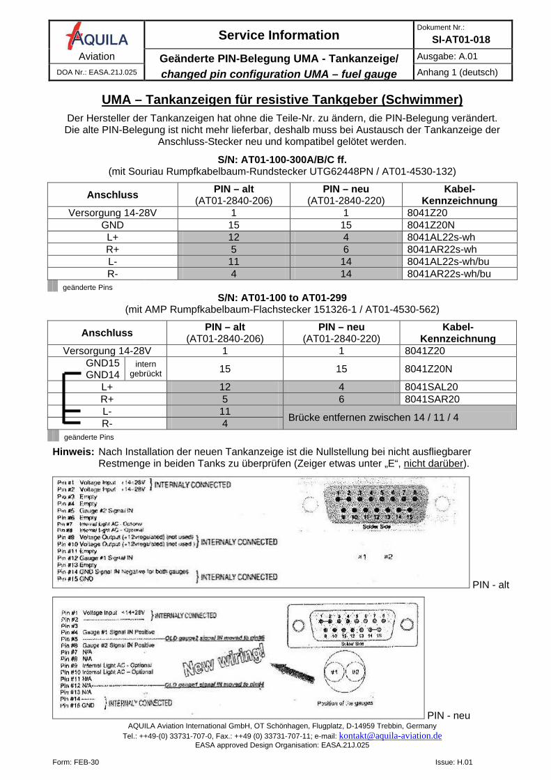
UMA – Tankanzeigen für resistive Tankgeber (Schwimmer)
Der Hersteller der Tankanzeigen hat ohne die Teile-Nr. zu ändern, die PIN-Belegung verändert. Die alte PIN-Belegung ist nicht mehr lieferbar, deshalb muss bei Austausch der Tankanzeige der
Anschluss-Stecker neu und kompatibel gelötet werden.
S/N: AT01-100-300A/B/C ff. (mit Souriau Rumpfkabelbaum-Rundstecker UTG62448PN / AT01-4530-132)
Anschluss PIN – alt (AT01-2840-206)
PIN – neu (AT01-2840-220)
Kabel-Kennzeichnung
Versorgung 14-28V 1 1 8041Z20 GND 15 15 8041Z20N L+ 12 4 8041AL22s-wh R+ 5 6 8041AR22s-wh L- 11 14 8041AL22s-wh/bu R- 4 14 8041AR22s-wh/bu
geänderte Pins S/N: AT01-100 to AT01-299
(mit AMP Rumpfkabelbaum-Flachstecker 151326-1 / AT01-4530-562)
Anschluss PIN – alt (AT01-2840-206)
PIN – neu (AT01-2840-220)
Kabel-Kennzeichnung
Versorgung 14-28V 1 1 8041Z20 GND15
GND14 intern
gebrückt 15 15 8041Z20N
L+ 12 4 8041SAL20 R+ 5 6 8041SAR20 L- 11 Brücke entfernen zwischen 14 / 11 / 4 R- 4
geänderte Pins
Hinweis: Nach Installation der neuen Tankanzeige ist die Nullstellung bei nicht ausfliegbarer Restmenge in beiden Tanks zu überprüfen (Zeiger etwas unter „E“, nicht darüber).
PIN - alt
PIN - neu
Service Information Dokument Nr.:
SI-AT01-018 Aviation Geänderte PIN-Belegung UMA - Tankanzeige/
changed pin configuration UMA – fuel gauge
Issue: A.01 DOA Nr.: EASA.21J.025 annex 1 (english)
AQUILA Aviation International GmbH, OT Schönhagen, Flugplatz, D-14959 Trebbin, Germany Tel.: ++49-(0) 33731-707-0, Fax.: ++49 (0) 33731-707-11; e-mail: [email protected]
EASA approved Design Organisation: EASA.21J.025
Form: FEB-30 Issue: H.01
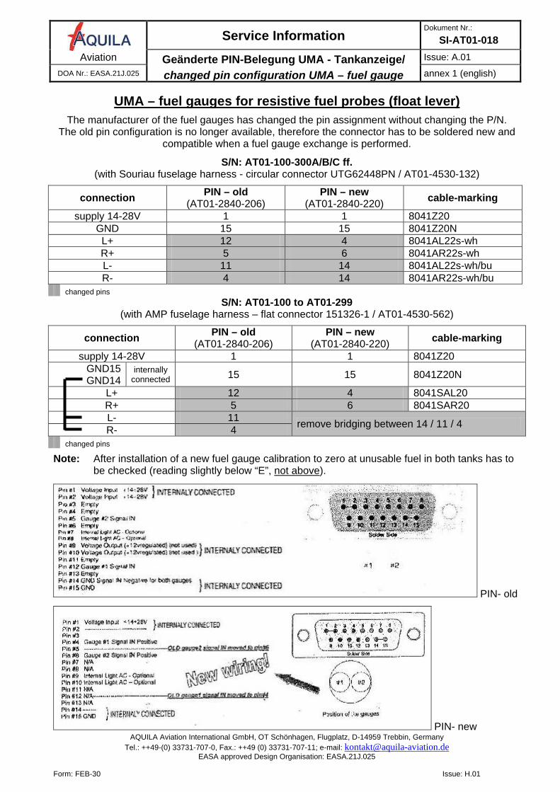
UMA – fuel gauges for resistive fuel probes (float lever)
The manufacturer of the fuel gauges has changed the pin assignment without changing the P/N. The old pin configuration is no longer available, therefore the connector has to be soldered new and
compatible when a fuel gauge exchange is performed.
S/N: AT01-100-300A/B/C ff. (with Souriau fuselage harness - circular connector UTG62448PN / AT01-4530-132)
connection PIN – old (AT01-2840-206)
PIN – new (AT01-2840-220) cable-marking
supply 14-28V 1 1 8041Z20 GND 15 15 8041Z20N L+ 12 4 8041AL22s-wh R+ 5 6 8041AR22s-wh L- 11 14 8041AL22s-wh/bu R- 4 14 8041AR22s-wh/bu
changed pins S/N: AT01-100 to AT01-299
(with AMP fuselage harness – flat connector 151326-1 / AT01-4530-562)
connection PIN – old (AT01-2840-206)
PIN – new (AT01-2840-220) cable-marking
supply 14-28V 1 1 8041Z20 GND15
GND14 internally
connected 15 15 8041Z20N
L+ 12 4 8041SAL20 R+ 5 6 8041SAR20 L- 11 remove bridging between 14 / 11 / 4 R- 4
changed pins
Note: After installation of a new fuel gauge calibration to zero at unusable fuel in both tanks has to be checked (reading slightly below “E”, not above).
PIN- old
PIN- new
Service Information Dokument Nr.:
SI-AT01-018 Aviation Umrüstung Aviasport auf UMA - Drehzahlmesser/
Retrofit from Aviasport to UMA – tachometer
Ausgabe: A.01 DOA Nr.: EASA.21J.025 Anhang 2 (deutsch)
AQUILA Aviation International GmbH, OT Schönhagen, Flugplatz, D-14959 Trebbin, Germany Tel.: ++49-(0) 33731-707-0, Fax.: ++49 (0) 33731-707-11; e-mail: [email protected]
EASA approved Design Organisation: EASA.21J.025
Form: FEB-30 Issue: H.01
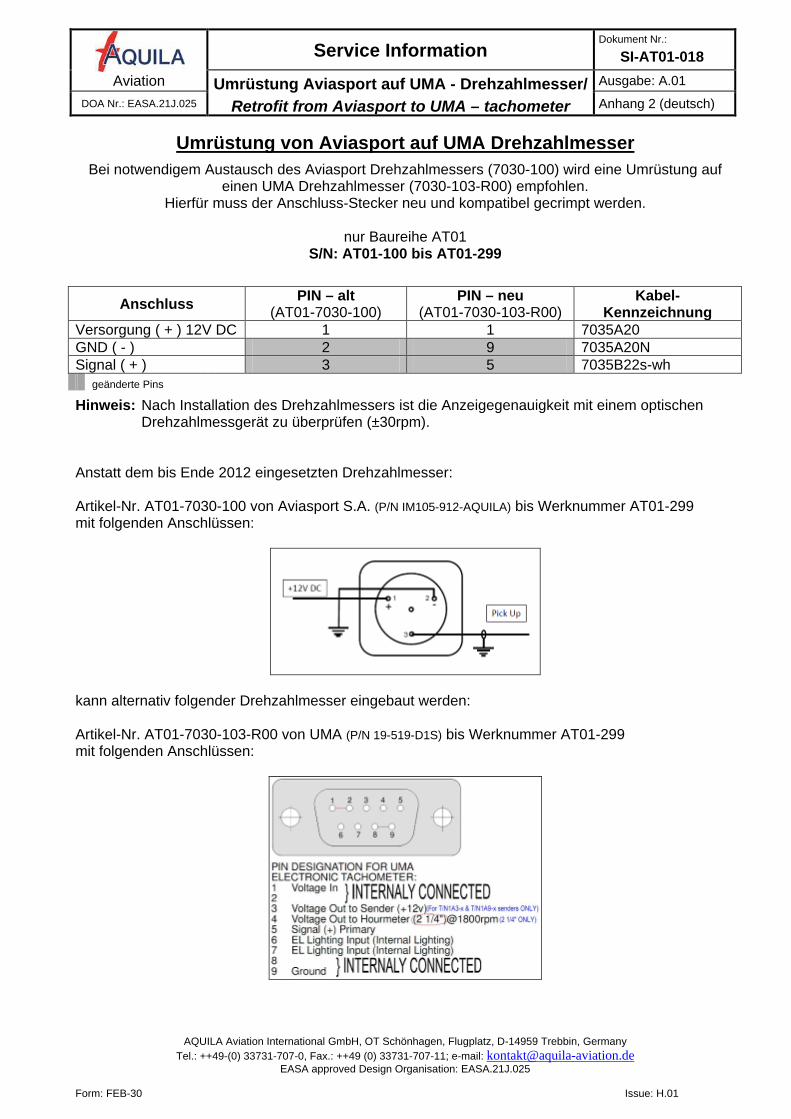
Umrüstung von Aviasport auf UMA Drehzahlmesser
Bei notwendigem Austausch des Aviasport Drehzahlmessers (7030-100) wird eine Umrüstung auf einen UMA Drehzahlmesser (7030-103-R00) empfohlen.
Hierfür muss der Anschluss-Stecker neu und kompatibel gecrimpt werden.
nur Baureihe AT01 S/N: AT01-100 bis AT01-299
Anschluss PIN – alt (AT01-7030-100)
PIN – neu (AT01-7030-103-R00)
Kabel-Kennzeichnung
Versorgung ( + ) 12V DC 1 1 7035A20 GND ( - ) 2 9 7035A20N Signal ( + ) 3 5 7035B22s-wh geänderte Pins
Hinweis: Nach Installation des Drehzahlmessers ist die Anzeigegenauigkeit mit einem optischen Drehzahlmessgerät zu überprüfen (±30rpm). Anstatt dem bis Ende 2012 eingesetzten Drehzahlmesser: Artikel-Nr. AT01-7030-100 von Aviasport S.A. (P/N IM105-912-AQUILA) bis Werknummer AT01-299 mit folgenden Anschlüssen:
kann alternativ folgender Drehzahlmesser eingebaut werden: Artikel-Nr. AT01-7030-103-R00 von UMA (P/N 19-519-D1S) bis Werknummer AT01-299 mit folgenden Anschlüssen:
Service Information Dokument Nr.:
SI-AT01-018 Aviation Umrüstung Aviasport auf UMA - Drehzahlmesser/
Retrofit from Aviasport to UMA – tachometer
Issue: A.01 DOA Nr.: EASA.21J.025 annex 2 (english)
AQUILA Aviation International GmbH, OT Schönhagen, Flugplatz, D-14959 Trebbin, Germany Tel.: ++49-(0) 33731-707-0, Fax.: ++49 (0) 33731-707-11; e-mail: [email protected]
EASA approved Design Organisation: EASA.21J.025
Form: FEB-30 Issue: H.01
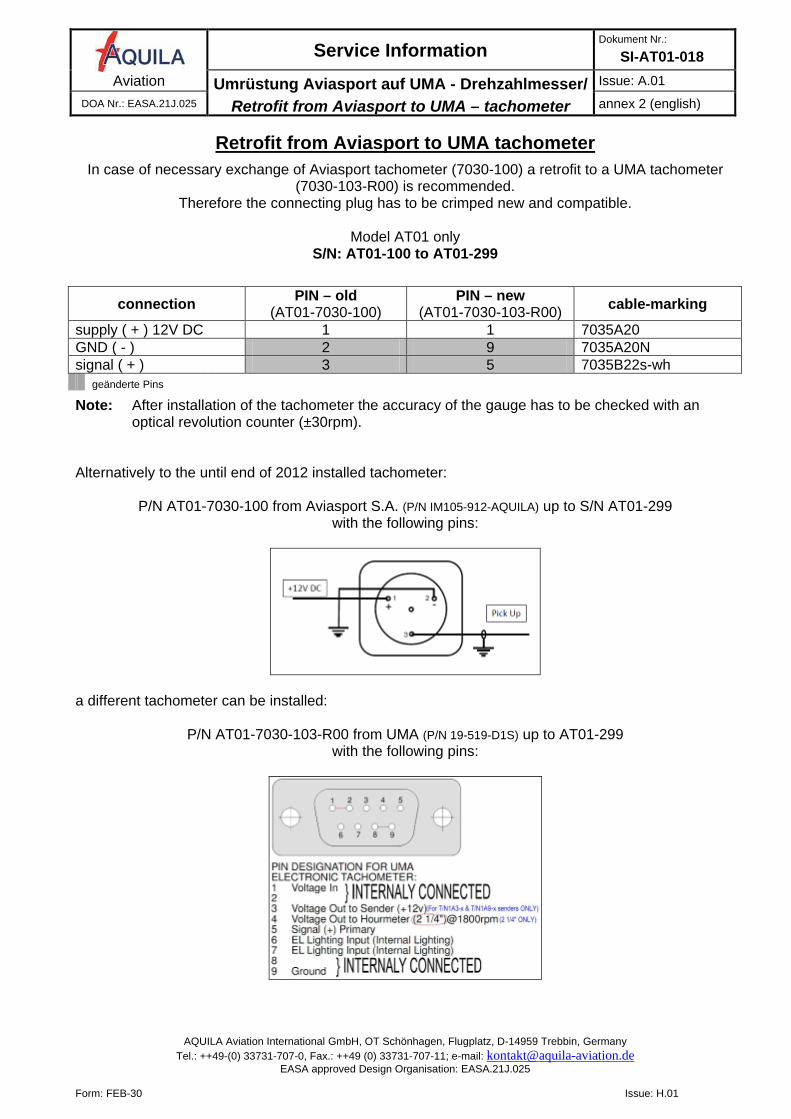
Retrofit from Aviasport to UMA tachometer
In case of necessary exchange of Aviasport tachometer (7030-100) a retrofit to a UMA tachometer (7030-103-R00) is recommended.
Therefore the connecting plug has to be crimped new and compatible.
Model AT01 only S/N: AT01-100 to AT01-299
connection PIN – old (AT01-7030-100)
PIN – new (AT01-7030-103-R00) cable-marking
supply ( + ) 12V DC 1 1 7035A20 GND ( - ) 2 9 7035A20N signal ( + ) 3 5 7035B22s-wh geänderte Pins
Note: After installation of the tachometer the accuracy of the gauge has to be checked with an optical revolution counter (±30rpm). Alternatively to the until end of 2012 installed tachometer:
P/N AT01-7030-100 from Aviasport S.A. (P/N IM105-912-AQUILA) up to S/N AT01-299 with the following pins:
a different tachometer can be installed:
P/N AT01-7030-103-R00 from UMA (P/N 19-519-D1S) up to AT01-299 with the following pins:
Service Information Dokument Nr.:
SI-AT01-018 Aviation Verbesserter Triebwerksbedienungs-Quadrant /
Improved Engine Control Quadrant
Ausgabe: A.01 DOA Nr.: EASA.21J.025 Anhang 3 (deutsch)
AQUILA Aviation International GmbH, OT Schönhagen, Flugplatz, D-14959 Trebbin, Germany Tel.: ++49-(0) 33731-707-0, Fax.: ++49 (0) 33731-707-11; e-mail: [email protected]
EASA approved Design Organisation: EASA.21J.025
Form: FEB-30 Issue: H.01
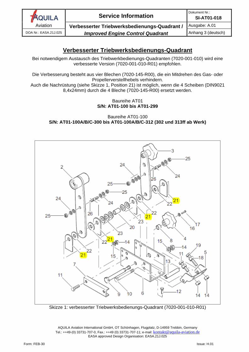
Verbesserter Triebwerksbedienungs-Quadrant
Bei notwendigem Austausch des Triebwerkbedienungs-Quadranten (7020-001-010) wird eine verbesserte Version (7020-001-010-R01) empfohlen.
Die Verbesserung besteht aus vier Blechen (7020-145-R00), die ein Mitdrehen des Gas- oder
Propellerverstellhebels verhindern. Auch die Nachrüstung (siehe Skizze 1, Position 21) ist möglich, wenn die 4 Scheiben (DIN9021
8,4x24mm) durch die 4 Bleche (7020-145-R00) ersetzt werden.
Baureihe AT01 S/N: AT01-100 bis AT01-299
Baureihe AT01-100
S/N: AT01-100A/B/C-300 bis AT01-100A/B/C-312 (302 und 313ff ab Werk)
Skizze 1: verbesserter Triebwerksbedienungs-Quadrant (7020-001-010-R01)
Service Information Dokument Nr.:
SI-AT01-018 Aviation Verbesserter Triebwerksbedienungs-Quadrant /
Improved Engine Control Quadrant
Issue: A.01 DOA Nr.: EASA.21J.025 annex 3 (english)
AQUILA Aviation International GmbH, OT Schönhagen, Flugplatz, D-14959 Trebbin, Germany Tel.: ++49-(0) 33731-707-0, Fax.: ++49 (0) 33731-707-11; e-mail: [email protected]
EASA approved Design Organisation: EASA.21J.025
Form: FEB-30 Issue: H.01
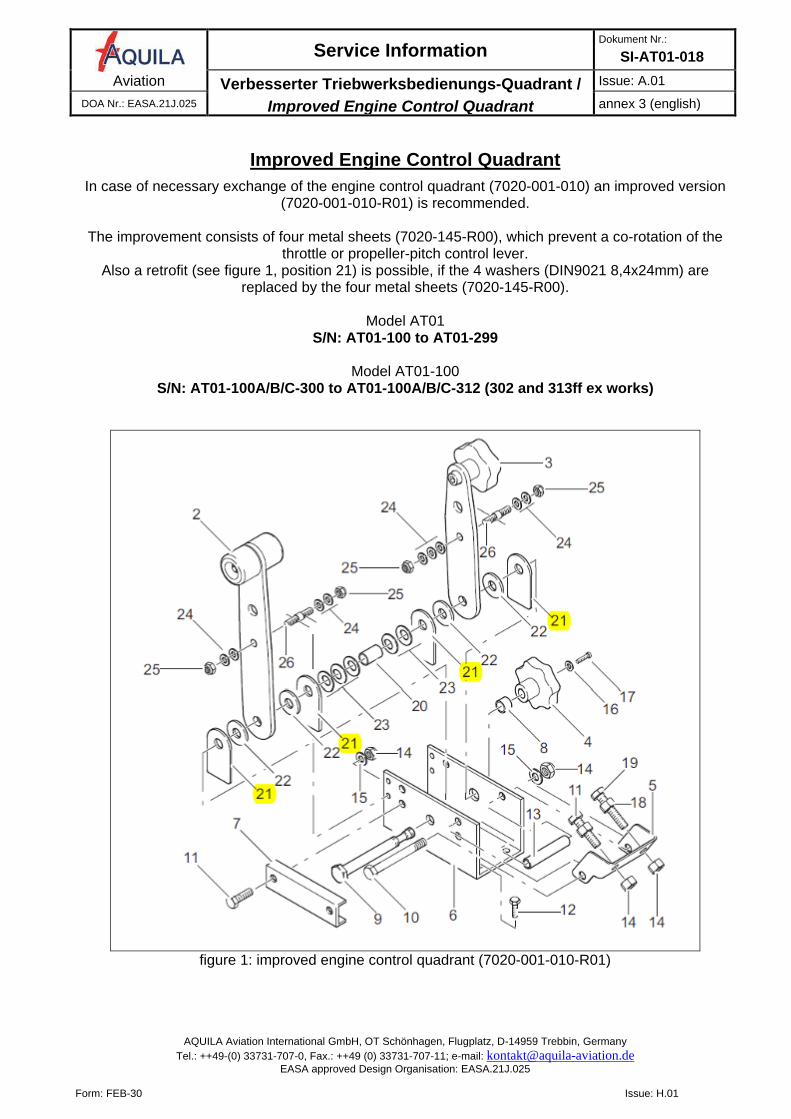
Improved Engine Control Quadrant
In case of necessary exchange of the engine control quadrant (7020-001-010) an improved version (7020-001-010-R01) is recommended.
The improvement consists of four metal sheets (7020-145-R00), which prevent a co-rotation of the
throttle or propeller-pitch control lever. Also a retrofit (see figure 1, position 21) is possible, if the 4 washers (DIN9021 8,4x24mm) are
replaced by the four metal sheets (7020-145-R00).
Model AT01 S/N: AT01-100 to AT01-299
Model AT01-100
S/N: AT01-100A/B/C-300 to AT01-100A/B/C-312 (302 and 313ff ex works)
figure 1: improved engine control quadrant (7020-001-010-R01)
Service Information Dokument Nr.:
SI-AT01-018 Aviation alt. Achsschraube / Lagerbuchsen / Achse BFW /
alt. NLG axle bolt / bearing races / axle
Ausgabe: A.02 DOA Nr.: EASA.21J.025 Anhang 4 (deutsch)
AQUILA Aviation International GmbH, OT Schönhagen, Flugplatz, D-14959 Trebbin, Germany Tel.: ++49-(0) 33731-707-0, Fax.: ++49 (0) 33731-707-11; e-mail: [email protected]
EASA approved Design Organisation: EASA.21J.025
Form: FEB-30 Issue: H.01
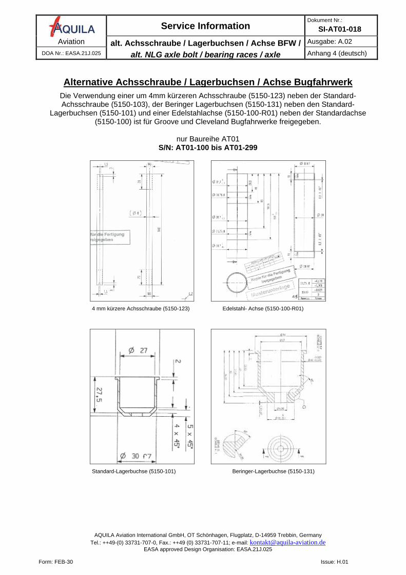
Alternative Achsschraube / Lagerbuchsen / Achse Bugfahrwerk
Die Verwendung einer um 4mm kürzeren Achsschraube (5150-123) neben der Standard-Achsschraube (5150-103), der Beringer Lagerbuchsen (5150-131) neben den Standard-
Lagerbuchsen (5150-101) und einer Edelstahlachse (5150-100-R01) neben der Standardachse (5150-100) ist für Groove und Cleveland Bugfahrwerke freigegeben.
nur Baureihe AT01
S/N: AT01-100 bis AT01-299
4 mm kürzere Achsschraube (5150-123) Edelstahl- Achse (5150-100-R01)
Standard-Lagerbuchse (5150-101) Beringer-Lagerbuchse (5150-131)
Service Information Dokument Nr.:
SI-AT01-018 Aviation alt. Achsschraube / Lagerbuchsen / Achse BFW /
alt. NLG axle bolt / bearing races / axle
Issue: A.02 DOA Nr.: EASA.21J.025 annex 4 (english)
AQUILA Aviation International GmbH, OT Schönhagen, Flugplatz, D-14959 Trebbin, Germany Tel.: ++49-(0) 33731-707-0, Fax.: ++49 (0) 33731-707-11; e-mail: [email protected]
EASA approved Design Organisation: EASA.21J.025
Form: FEB-30 Issue: H.01
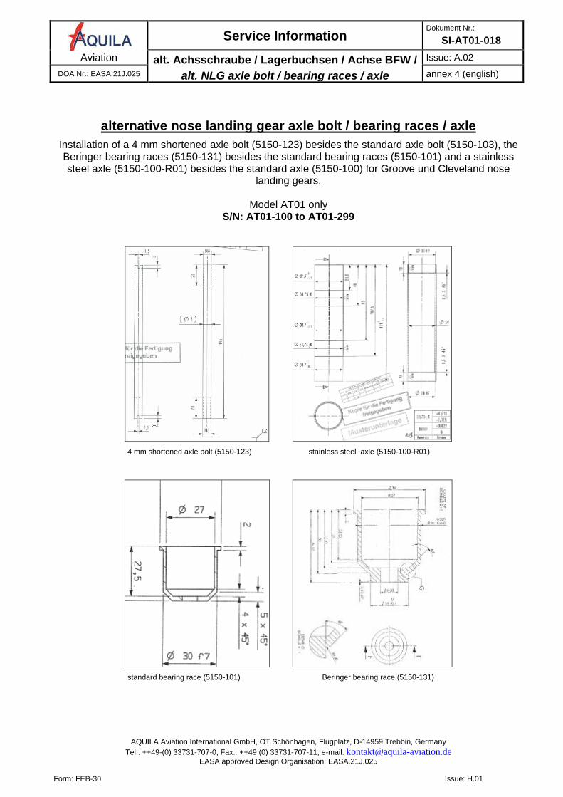
alternative nose landing gear axle bolt / bearing races / axle
Installation of a 4 mm shortened axle bolt (5150-123) besides the standard axle bolt (5150-103), the Beringer bearing races (5150-131) besides the standard bearing races (5150-101) and a stainless steel axle (5150-100-R01) besides the standard axle (5150-100) for Groove und Cleveland nose
landing gears.
Model AT01 only S/N: AT01-100 to AT01-299
4 mm shortened axle bolt (5150-123) stainless steel axle (5150-100-R01)
standard bearing race (5150-101) Beringer bearing race (5150-131)
Service Information Dokument Nr.:
SI-AT01-018 Aviation Drainage mech. KS-Pumpe /
mech. fuel pump drainage
Ausgabe: A.01 DOA Nr.: EASA.21J.025 Anhang 5 (deutsch)
AQUILA Aviation International GmbH, OT Schönhagen, Flugplatz, D-14959 Trebbin, Germany Tel.: ++49-(0) 33731-707-0, Fax.: ++49 (0) 33731-707-11; e-mail: [email protected]
EASA approved Design Organisation: EASA.21J.025
Form: FEB-30 Issue: H.01
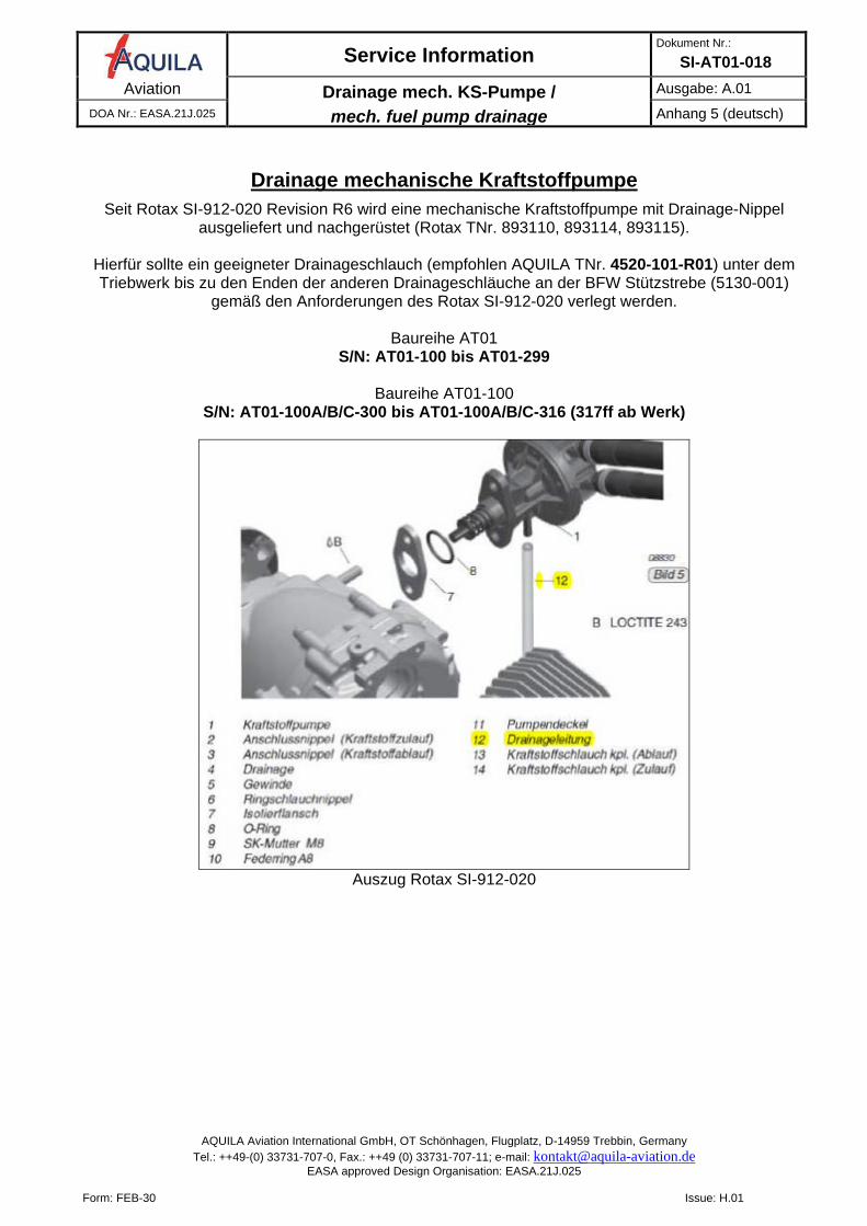
Drainage mechanische Kraftstoffpumpe
Seit Rotax SI-912-020 Revision R6 wird eine mechanische Kraftstoffpumpe mit Drainage-Nippel ausgeliefert und nachgerüstet (Rotax TNr. 893110, 893114, 893115).
Hierfür sollte ein geeigneter Drainageschlauch (empfohlen AQUILA TNr. 4520-101-R01) unter dem Triebwerk bis zu den Enden der anderen Drainageschläuche an der BFW Stützstrebe (5130-001)
gemäß den Anforderungen des Rotax SI-912-020 verlegt werden.
Baureihe AT01 S/N: AT01-100 bis AT01-299
Baureihe AT01-100
S/N: AT01-100A/B/C-300 bis AT01-100A/B/C-316 (317ff ab Werk)
Auszug Rotax SI-912-020
Service Information Dokument Nr.:
SI-AT01-018 Aviation Drainage mech. KS-Pumpe /
mech. fuel pump drainage
Issue: A.01 DOA Nr.: EASA.21J.025 annex 5 (english)
AQUILA Aviation International GmbH, OT Schönhagen, Flugplatz, D-14959 Trebbin, Germany Tel.: ++49-(0) 33731-707-0, Fax.: ++49 (0) 33731-707-11; e-mail: [email protected]
EASA approved Design Organisation: EASA.21J.025
Form: FEB-30 Issue: H.01
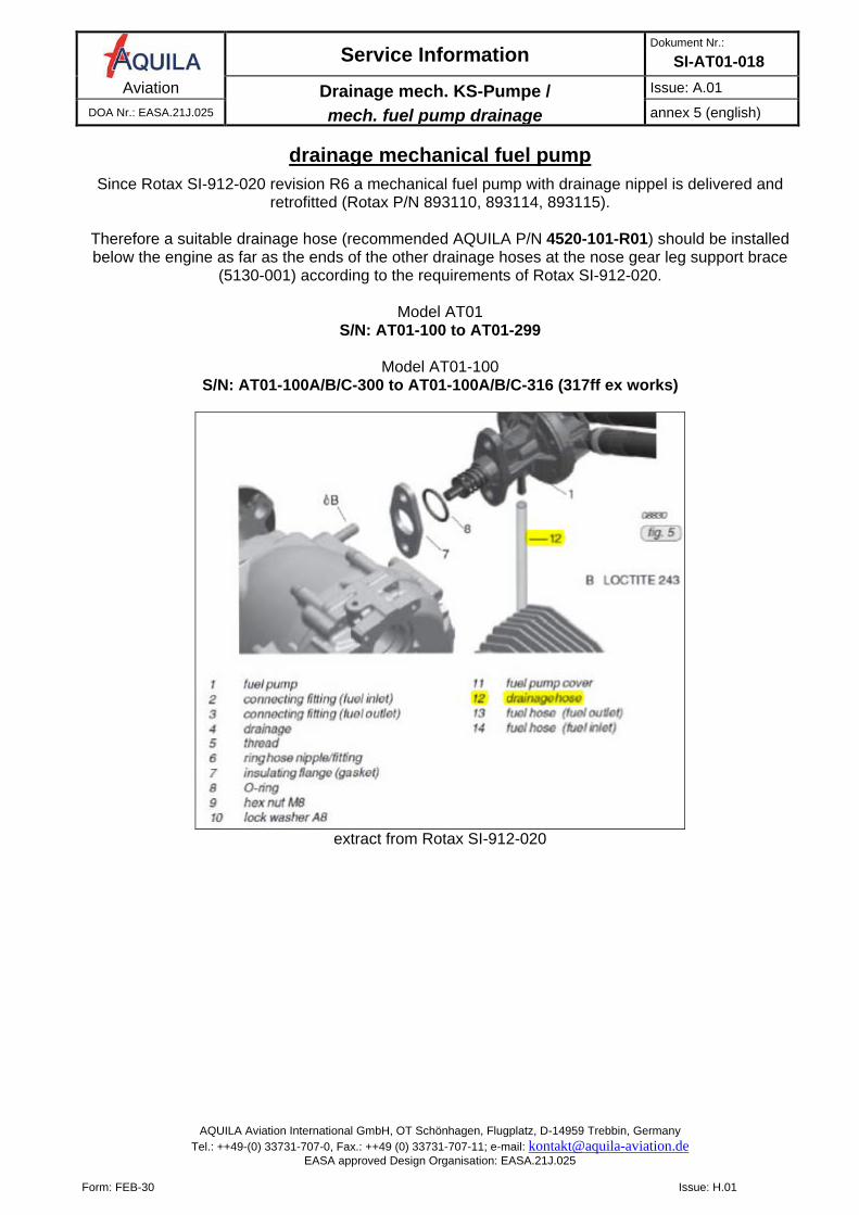
drainage mechanical fuel pump
Since Rotax SI-912-020 revision R6 a mechanical fuel pump with drainage nippel is delivered and retrofitted (Rotax P/N 893110, 893114, 893115).
Therefore a suitable drainage hose (recommended AQUILA P/N 4520-101-R01) should be installed below the engine as far as the ends of the other drainage hoses at the nose gear leg support brace
(5130-001) according to the requirements of Rotax SI-912-020.
Model AT01 S/N: AT01-100 to AT01-299
Model AT01-100
S/N: AT01-100A/B/C-300 to AT01-100A/B/C-316 (317ff ex works)
extract from Rotax SI-912-020
Service Information Dokument Nr.:
SI-AT01-018 Aviation Batteriehalterung /
battery mount
Ausgabe: A.01 DOA Nr.: EASA.21J.025 Anhang 6 (deutsch)
AQUILA Aviation International GmbH, OT Schönhagen, Flugplatz, D-14959 Trebbin, Germany Tel.: ++49-(0) 33731-707-0, Fax.: ++49 (0) 33731-707-11; e-mail: [email protected]
EASA approved Design Organisation: EASA.21J.025
Form: FEB-30 Issue: H.01
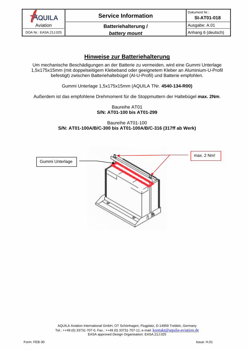
Hinweise zur Batteriehalterung
Um mechanische Beschädigungen an der Batterie zu vermeiden, wird eine Gummi Unterlage 1,5x175x15mm (mit doppelseitigem Klebeband oder geeignetem Kleber an Aluminium-U-Profil
befestigt) zwischen Batteriehaltebügel (Al-U-Profil) und Batterie empfohlen.
Gummi Unterlage 1,5x175x15mm (AQUILA TNr. 4540-134-R00)
Außerdem ist das empfohlene Drehmoment für die Stoppmuttern der Haltebügel max. 2Nm.
Baureihe AT01 S/N: AT01-100 bis AT01-299
Baureihe AT01-100
S/N: AT01-100A/B/C-300 bis AT01-100A/B/C-316 (317ff ab Werk)
max. 2 Nm! Gummi Unterlage
Service Information Dokument Nr.:
SI-AT01-018 Aviation Batteriehalterung /
battery mount
Issue: A.01 DOA Nr.: EASA.21J.025 annex 6 (english)
AQUILA Aviation International GmbH, OT Schönhagen, Flugplatz, D-14959 Trebbin, Germany Tel.: ++49-(0) 33731-707-0, Fax.: ++49 (0) 33731-707-11; e-mail: [email protected]
EASA approved Design Organisation: EASA.21J.025
Form: FEB-30 Issue: H.01
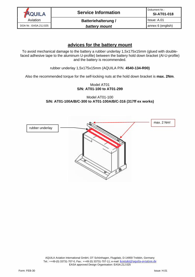
advices for the battery mount
To avoid mechanical damage to the battery a rubber underlay 1,5x175x15mm (glued with double-faced adhesive tape to the aluminum U-profile) between the battery hold down bracket (Al-U-profile)
and the battery is recommended.
rubber underlay 1,5x175x15mm (AQUILA P/N. 4540-134-R00)
Also the recommended torque for the self-locking nuts at the hold down bracket is max. 2Nm.
Model AT01 S/N: AT01-100 to AT01-299
Model AT01-100
S/N: AT01-100A/B/C-300 to AT01-100A/B/C-316 (317ff ex works)
max. 2 Nm!
rubber underlay
Service Information Dokument Nr.:
SI-AT01-018 Aviation Zugdurchführung Brandschott /
firewall cut-out engine control cables
Ausgabe: A.01 DOA Nr.: EASA.21J.025 Anhang 7 (deutsch)
AQUILA Aviation International GmbH, OT Schönhagen, Flugplatz, D-14959 Trebbin, Germany Tel.: ++49-(0) 33731-707-0, Fax.: ++49 (0) 33731-707-11; e-mail: [email protected]
EASA approved Design Organisation: EASA.21J.025
Form: FEB-30 Issue: H.01
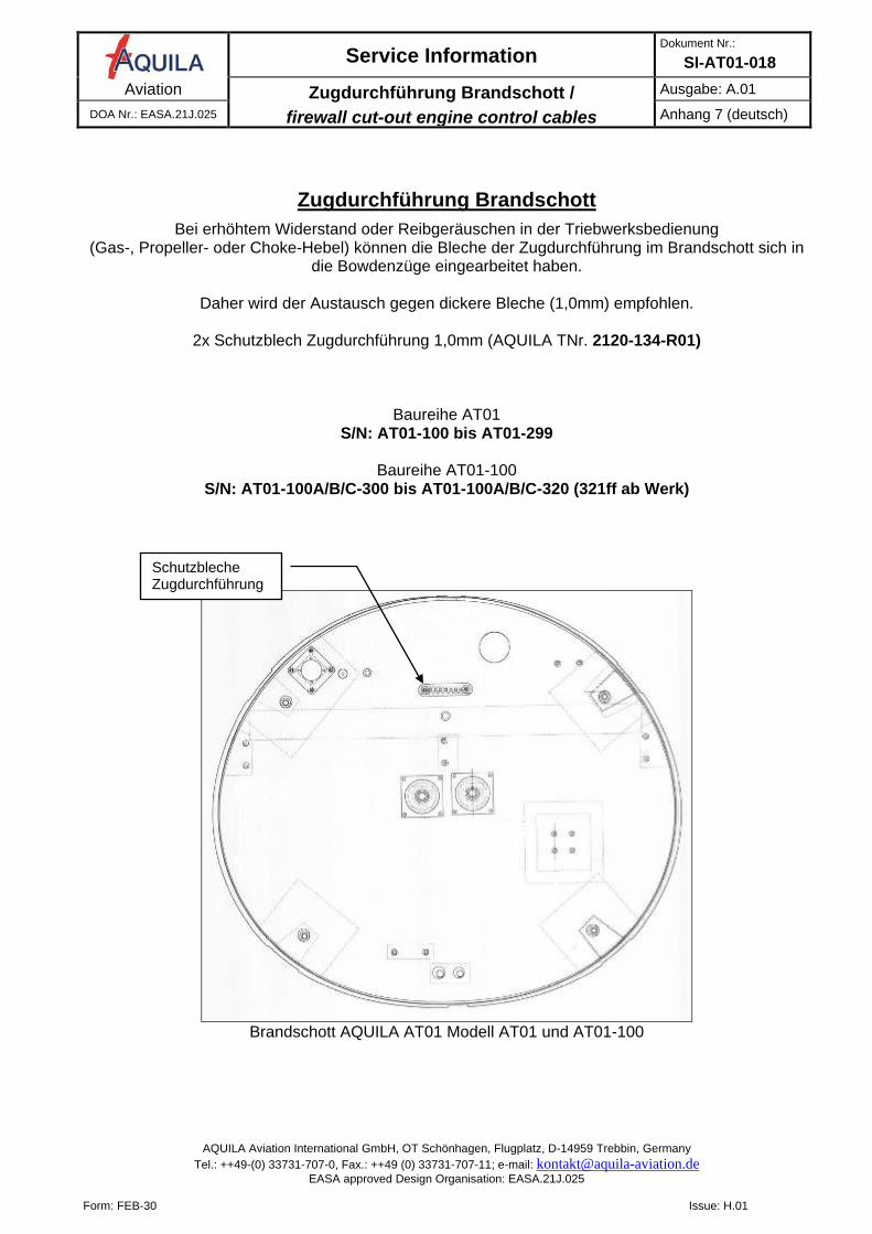
Zugdurchführung Brandschott
Bei erhöhtem Widerstand oder Reibgeräuschen in der Triebwerksbedienung (Gas-, Propeller- oder Choke-Hebel) können die Bleche der Zugdurchführung im Brandschott sich in
die Bowdenzüge eingearbeitet haben.
Daher wird der Austausch gegen dickere Bleche (1,0mm) empfohlen.
2x Schutzblech Zugdurchführung 1,0mm (AQUILA TNr. 2120-134-R01)
Baureihe AT01
S/N: AT01-100 bis AT01-299
Baureihe AT01-100 S/N: AT01-100A/B/C-300 bis AT01-100A/B/C-320 (321ff ab Werk)
Brandschott AQUILA AT01 Modell AT01 und AT01-100
Schutzbleche Zugdurchführung
Service Information Dokument Nr.:
SI-AT01-018 Aviation Zugdurchführung Brandschott /
firewall cut-out engine control cables
Issue: A.01 DOA Nr.: EASA.21J.025 annex 7 (english)
AQUILA Aviation International GmbH, OT Schönhagen, Flugplatz, D-14959 Trebbin, Germany Tel.: ++49-(0) 33731-707-0, Fax.: ++49 (0) 33731-707-11; e-mail: [email protected]
EASA approved Design Organisation: EASA.21J.025
Form: FEB-30 Issue: H.01
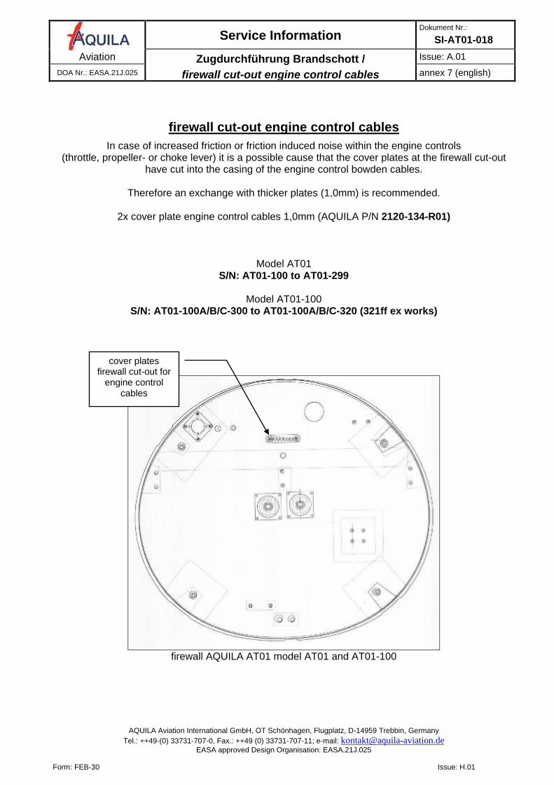
firewall cut-out engine control cables
In case of increased friction or friction induced noise within the engine controls (throttle, propeller- or choke lever) it is a possible cause that the cover plates at the firewall cut-out
have cut into the casing of the engine control bowden cables.
Therefore an exchange with thicker plates (1,0mm) is recommended.
2x cover plate engine control cables 1,0mm (AQUILA P/N 2120-134-R01)
Model AT01
S/N: AT01-100 to AT01-299
Model AT01-100 S/N: AT01-100A/B/C-300 to AT01-100A/B/C-320 (321ff ex works)
firewall AQUILA AT01 model AT01 and AT01-100
cover plates firewall cut-out for
engine control cables
Service Information Dokument Nr.:
SI-AT01-018 Aviation Verlängertes Drainventil am Tragflügel /
extended drain valve at wing
Ausgabe: A.02 DOA Nr.: EASA.21J.025 Anhang 8 (deutsch)
AQUILA Aviation International GmbH, OT Schönhagen, Flugplatz, D-14959 Trebbin, Germany Tel.: ++49-(0) 33731-707-0, Fax.: ++49 (0) 33731-707-11; e-mail: [email protected]
EASA approved Design Organisation: EASA.21J.025
Form: FEB-30 Issue: H.01
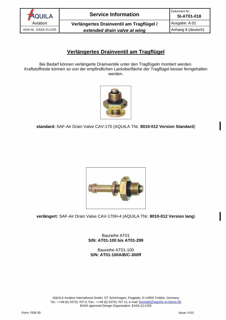
Verlängertes Drainventil am Tragflügel
Bei Bedarf können verlängerte Drainventile unter den Tragflügeln montiert werden.
Kraftstoffreste können so von der empfindlichen Lackoberfläche der Tragflügel besser ferngehalten werden.
standard: SAF-Air Drain Valve CAV-170 (AQUILA TNr. 8010-012 Version Standard)
verlängert: SAF-Air Drain Valve CAV-170H-4 (AQUILA TNr. 8010-012 Version lang)
Baureihe AT01
S/N: AT01-100 bis AT01-299
Baureihe AT01-100 S/N: AT01-100A/B/C-300ff
Service Information Dokument Nr.:
SI-AT01-018 Aviation Verlängertes Drainventil am Tragflügel /
extended drain valve at wing
Issue: A.02 DOA Nr.: EASA.21J.025 annex 8 (english)
AQUILA Aviation International GmbH, OT Schönhagen, Flugplatz, D-14959 Trebbin, Germany Tel.: ++49-(0) 33731-707-0, Fax.: ++49 (0) 33731-707-11; e-mail: [email protected]
EASA approved Design Organisation: EASA.21J.025
Form: FEB-30 Issue: H.01
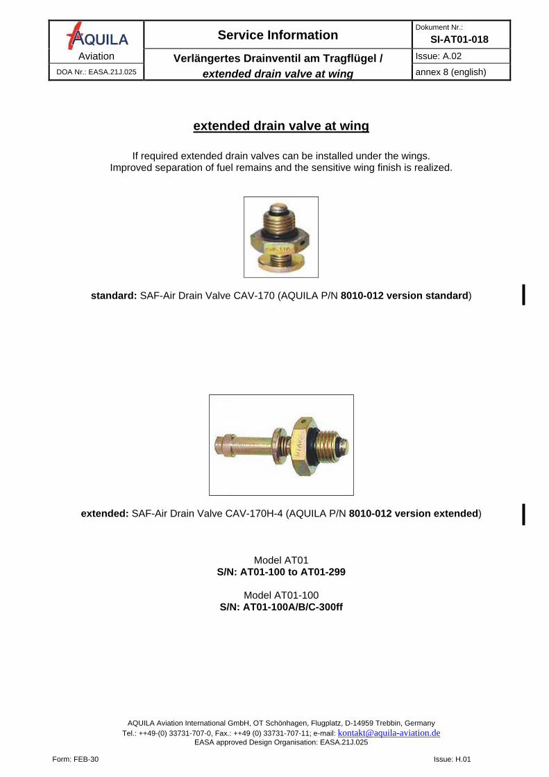
extended drain valve at wing
If required extended drain valves can be installed under the wings.
Improved separation of fuel remains and the sensitive wing finish is realized.
standard: SAF-Air Drain Valve CAV-170 (AQUILA P/N 8010-012 version standard)
extended: SAF-Air Drain Valve CAV-170H-4 (AQUILA P/N 8010-012 version extended)
Model AT01
S/N: AT01-100 to AT01-299
Model AT01-100 S/N: AT01-100A/B/C-300ff
Service Information Dokument Nr.:
SI-AT01-018 Aviation Nachrüstung Kondensator für ext. Generator /
retrofit of a capacitor for the external generator
Ausgabe: A.01 DOA Nr.: EASA.21J.025 Anhang 9 (deutsch)
AQUILA Aviation International GmbH, OT Schönhagen, Flugplatz, D-14959 Trebbin, Germany Tel.: ++49-(0) 33731-707-0, Fax.: ++49 (0) 33731-707-11; e-mail: [email protected]
EASA approved Design Organisation: EASA.21J.025
Form: FEB-30 Issue: H.01
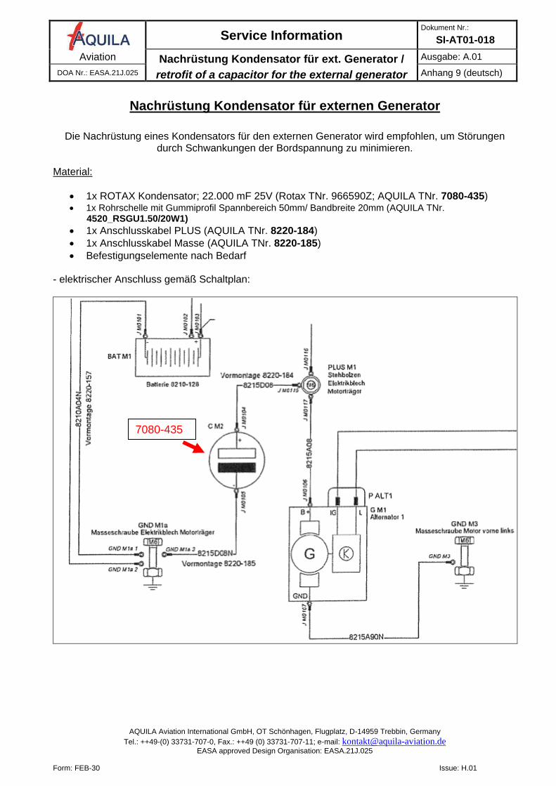
Nachrüstung Kondensator für externen Generator
Die Nachrüstung eines Kondensators für den externen Generator wird empfohlen, um Störungen
durch Schwankungen der Bordspannung zu minimieren.
Material:
• 1x ROTAX Kondensator; 22.000 mF 25V (Rotax TNr. 966590Z; AQUILA TNr. 7080-435) • 1x Rohrschelle mit Gummiprofil Spannbereich 50mm/ Bandbreite 20mm (AQUILA TNr.
4520_RSGU1.50/20W1) • 1x Anschlusskabel PLUS (AQUILA TNr. 8220-184) • 1x Anschlusskabel Masse (AQUILA TNr. 8220-185) • Befestigungselemente nach Bedarf
- elektrischer Anschluss gemäß Schaltplan:
7080-435
Service Information Dokument Nr.:
SI-AT01-018 Aviation Nachrüstung Kondensator für ext. Generator /
retrofit of a capacitor for the external generator
Ausgabe: A.01 DOA Nr.: EASA.21J.025 Anhang 9 (deutsch)
AQUILA Aviation International GmbH, OT Schönhagen, Flugplatz, D-14959 Trebbin, Germany Tel.: ++49-(0) 33731-707-0, Fax.: ++49 (0) 33731-707-11; e-mail: [email protected]
EASA approved Design Organisation: EASA.21J.025
Form: FEB-30 Issue: H.01
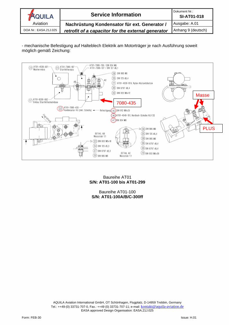
- mechanische Befestigung auf Halteblech Elektrik am Motorträger je nach Ausführung soweit möglich gemäß Zeichung:
Baureihe AT01 S/N: AT01-100 bis AT01-299
Baureihe AT01-100
S/N: AT01-100A/B/C-300ff
7080-435
Masse
PLUS
Service Information Dokument Nr.:
SI-AT01-018 Aviation Nachrüstung Kondensator für ext. Generator /
retrofit of a capacitor for the external generator
Issue: A.01 DOA Nr.: EASA.21J.025 annex 9 (english)
AQUILA Aviation International GmbH, OT Schönhagen, Flugplatz, D-14959 Trebbin, Germany Tel.: ++49-(0) 33731-707-0, Fax.: ++49 (0) 33731-707-11; e-mail: [email protected]
EASA approved Design Organisation: EASA.21J.025
Form: FEB-30 Issue: H.01
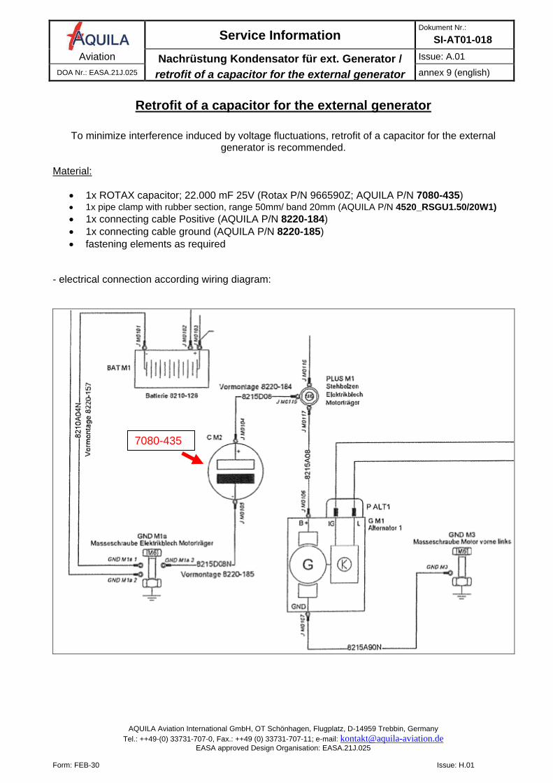
Retrofit of a capacitor for the external generator
To minimize interference induced by voltage fluctuations, retrofit of a capacitor for the external
generator is recommended.
Material:
• 1x ROTAX capacitor; 22.000 mF 25V (Rotax P/N 966590Z; AQUILA P/N 7080-435) • 1x pipe clamp with rubber section, range 50mm/ band 20mm (AQUILA P/N 4520_RSGU1.50/20W1) • 1x connecting cable Positive (AQUILA P/N 8220-184) • 1x connecting cable ground (AQUILA P/N 8220-185) • fastening elements as required
- electrical connection according wiring diagram:
7080-435
Service Information Dokument Nr.:
SI-AT01-018 Aviation Nachrüstung Kondensator für ext. Generator /
retrofit of a capacitor for the external generator
Issue: A.01 DOA Nr.: EASA.21J.025 annex 9 (english)
AQUILA Aviation International GmbH, OT Schönhagen, Flugplatz, D-14959 Trebbin, Germany Tel.: ++49-(0) 33731-707-0, Fax.: ++49 (0) 33731-707-11; e-mail: [email protected]
EASA approved Design Organisation: EASA.21J.025
Form: FEB-30 Issue: H.01
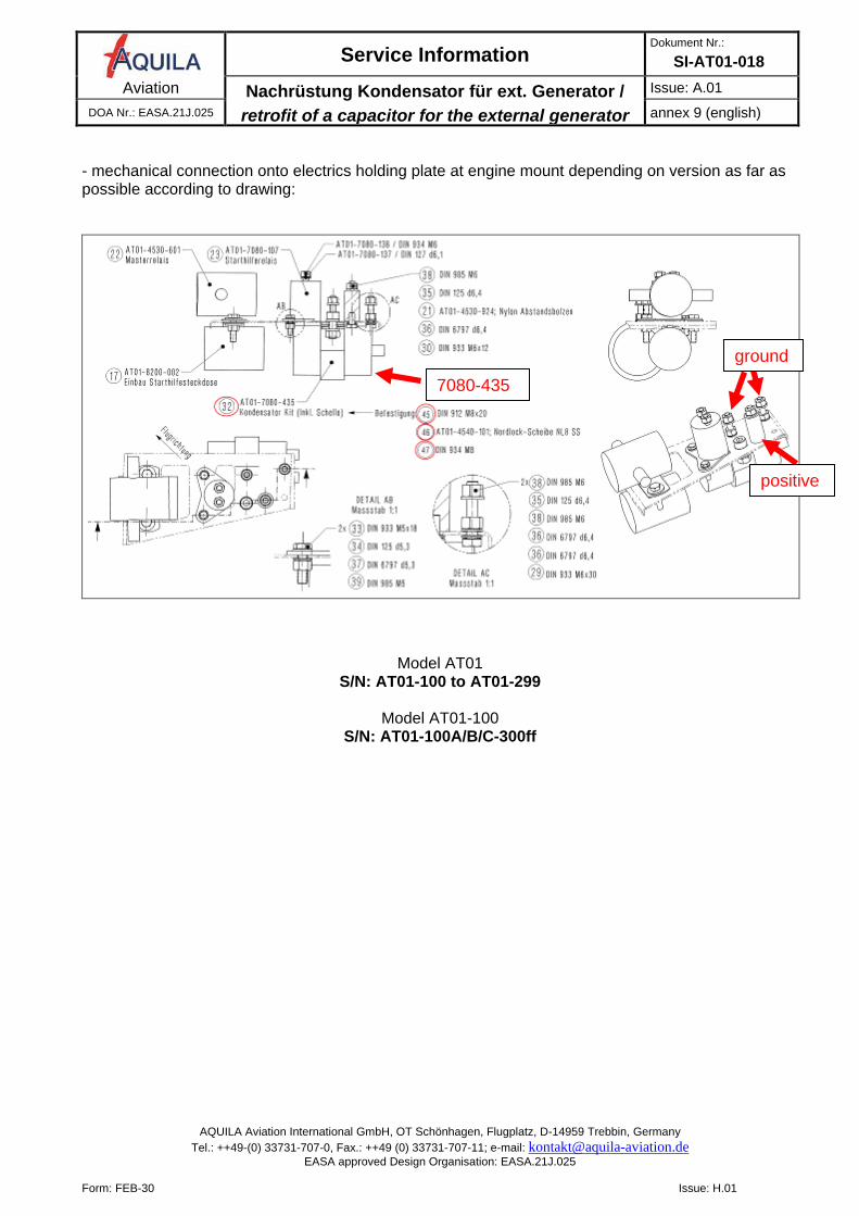
- mechanical connection onto electrics holding plate at engine mount depending on version as far as possible according to drawing:
Model AT01 S/N: AT01-100 to AT01-299
Model AT01-100
S/N: AT01-100A/B/C-300ff
7080-435
ground
positive
Service Information Dokument Nr.:
SI-AT01-018 Aviation Alternativer Dual Dimmer /
alternative dual dimmer
Ausgabe: A.01 DOA Nr.: EASA.21J.025 Anhang 10 (deutsch)
AQUILA Aviation International GmbH, OT Schönhagen, Flugplatz, D-14959 Trebbin, Germany Tel.: ++49-(0) 33731-707-0, Fax.: ++49 (0) 33731-707-11; e-mail: [email protected]
EASA approved Design Organisation: EASA.21J.025
Form: FEB-30 Issue: H.01
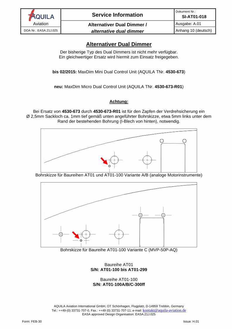
Alternativer Dual Dimmer
Der bisherige Typ des Dual Dimmers ist nicht mehr verfügbar. Ein gleichwertiger Ersatz wird hiermit zum Einsatz freigegeben.
bis 02/2015: MaxDim Mini Dual Control Unit (AQUILA TNr. 4530-673)
neu: MaxDim Micro Dual Control Unit (AQUILA TNr. 4530-673-R01)
Achtung:
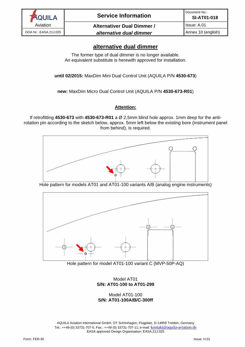
Bei Ersatz von 4530-673 durch 4530-673-R01 ist für den Zapfen der Verdrehsicherung ein Ø 2,5mm Sackloch ca. 1mm tief gemäß unten angeführter Bohrskizze, etwa 5mm links unter dem
Rand der bestehenden Bohrung (I-Blech von hinten), notwendig.
Bohrskizze für Baureihen AT01 und AT01-100 Variante A/B (analoge Motorinstrumente)
Bohrskizze für Baureihe AT01-100 Variante C (MVP-50P-AQ)
Baureihe AT01 S/N: AT01-100 bis AT01-299
Baureihe AT01-100
S/N: AT01-100A/B/C-300ff
Service Information Document No.:
SI-AT01-018 Aviation Alternativer Dual Dimmer /
alternative dual dimmer
Issue: A.01 DOA Nr.: EASA.21J.025 Annex 10 (english)
AQUILA Aviation International GmbH, OT Schönhagen, Flugplatz, D-14959 Trebbin, Germany Tel.: ++49-(0) 33731-707-0, Fax.: ++49 (0) 33731-707-11; e-mail: [email protected]
EASA approved Design Organisation: EASA.21J.025
Form: FEB-30 Issue: H.01
alternative dual dimmer
The former type of dual dimmer is no longer available. An equivalent substitute is herewith approved for installation.
until 02/2015: MaxDim Mini Dual Control Unit (AQUILA P/N 4530-673)
new: MaxDim Micro Dual Control Unit (AQUILA P/N 4530-673-R01)
Attention:
If retrofitting 4530-673 with 4530-673-R01 a Ø 2,5mm blind hole approx. 1mm deep for the anti-rotation pin according to the sketch below, approx. 5mm left below the existing bore (instrument panel
from behind), is required.
Hole pattern for models AT01 and AT01-100 variants A/B (analog engine instruments)
Hole pattern for model AT01-100 variant C (MVP-50P-AQ)
Model AT01 S/N: AT01-100 to AT01-299
Model AT01-100
S/N: AT01-100A/B/C-300ff
Service Information Dokument Nr.:
SI-AT01-018 Aviation 0,20mm KS-Rücklaufdrossel /
0,20mm fuel return line restrictor
Ausgabe: A.01 DOA Nr.: EASA.21J.025 Anhang 11 (deutsch)
AQUILA Aviation International GmbH, OT Schönhagen, Flugplatz, D-14959 Trebbin, Germany Tel.: ++49-(0) 33731-707-0, Fax.: ++49 (0) 33731-707-11; e-mail: [email protected]
EASA approved Design Organisation: EASA.21J.025
Form: FEB-30 Issue: H.01
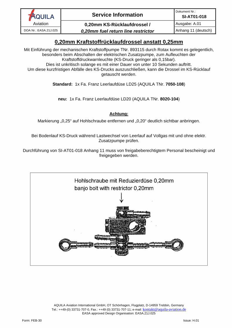
0,20mm Kraftstoffrücklaufdrossel anstatt 0,25mm
Mit Einführung der mechanischen Kraftstoffpumpe TNr. 893115 durch Rotax kommt es gelegentlich, besonders beim Abschalten der elektrischen Zusatzpumpe, zum Aufleuchten der
Kraftstoffdruckwarnleuchte (KS-Druck geringer als 0,15bar). Dies ist unkritisch solange es mit einer Dauer von unter 10 Sekunden auftritt.
Um diese kurzfristigen Abfälle des KS-Drucks auszuschließen, kann die Drossel im KS-Rücklauf getauscht werden.
Standard: 1x Fa. Franz Leerlaufdüse LD25 (AQUILA TNr. 7050-108)
neu: 1x Fa. Franz Leerlaufdüse LD20 (AQUILA TNr. 8020-104)
Achtung:
Markierung „0,25“ auf Hohlschraube entfernen und „0,20“ deutlich sichtbar anbringen.
Bei Bodenlauf KS-Druck während Lastwechsel von Leerlauf auf Vollgas mit und ohne elektr. Zusatzpumpe prüfen.
Durchführung von SI-AT01-018 Anhang 11 muss von freigabeberechtigtem Personal bescheinigt und
freigegeben werden.
Service Information Dokument Nr.:
SI-AT01-018 Aviation 0,20mm KS-Rücklaufdrossel /
0,20mm fuel return line restrictor
Issue: A.01 DOA Nr.: EASA.21J.025 annex 11 (english)
AQUILA Aviation International GmbH, OT Schönhagen, Flugplatz, D-14959 Trebbin, Germany Tel.: ++49-(0) 33731-707-0, Fax.: ++49 (0) 33731-707-11; e-mail: [email protected]
EASA approved Design Organisation: EASA.21J.025
Form: FEB-30 Issue: H.01
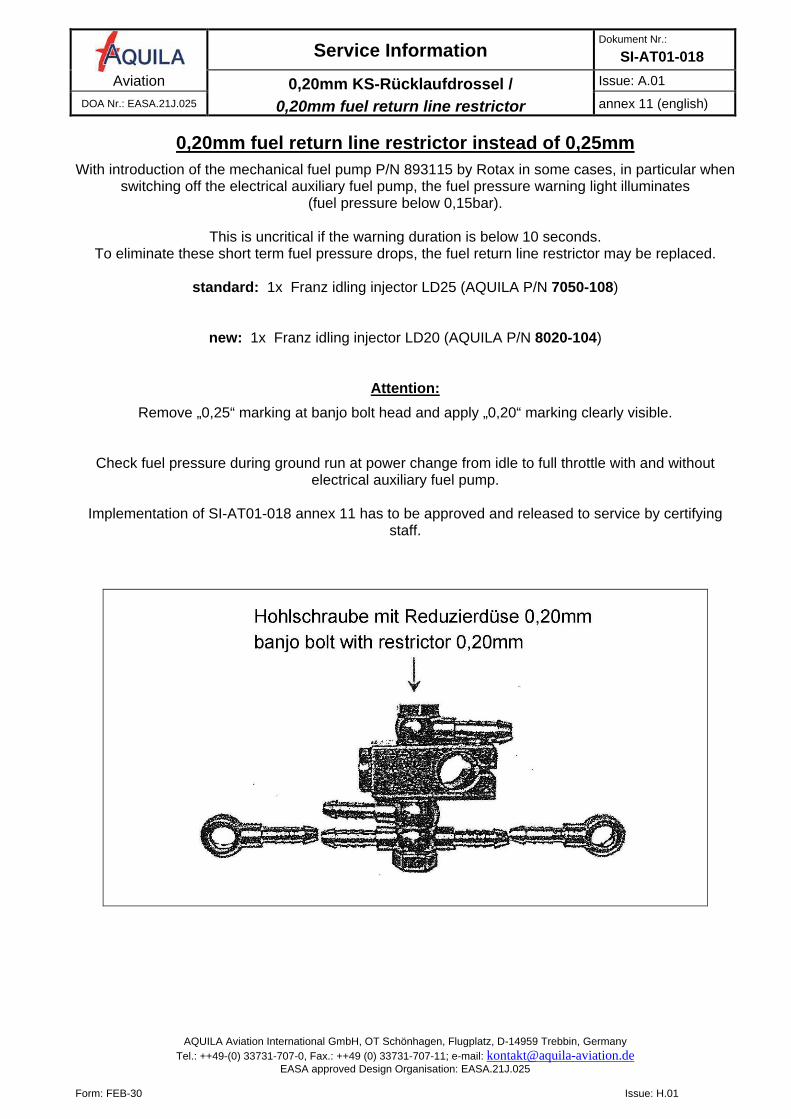
0,20mm fuel return line restrictor instead of 0,25mm
With introduction of the mechanical fuel pump P/N 893115 by Rotax in some cases, in particular when switching off the electrical auxiliary fuel pump, the fuel pressure warning light illuminates
(fuel pressure below 0,15bar).
This is uncritical if the warning duration is below 10 seconds. To eliminate these short term fuel pressure drops, the fuel return line restrictor may be replaced.
standard: 1x Franz idling injector LD25 (AQUILA P/N 7050-108)
new: 1x Franz idling injector LD20 (AQUILA P/N 8020-104)
Attention:
Remove „0,25“ marking at banjo bolt head and apply „0,20“ marking clearly visible.
Check fuel pressure during ground run at power change from idle to full throttle with and without electrical auxiliary fuel pump.
Implementation of SI-AT01-018 annex 11 has to be approved and released to service by certifying
staff.
Service Information Dokument Nr.:
SI-AT01-018 Aviation Kalibrierung Tankanzeigen mit Schwimmern /
calibration of float-type fuel gauges
Ausgabe: A.01 DOA Nr.: EASA.21J.025 Anhang 12 (deutsch)
AQUILA Aviation International GmbH, OT Schönhagen, Flugplatz, D-14959 Trebbin, Germany Tel.: ++49-(0) 33731-707-0, Fax.: ++49 (0) 33731-707-11; e-mail: [email protected]
EASA approved Design Organisation: EASA.21J.025
Form: FEB-30 Issue: H.01
Kalibrierung Tankanzeigen mit Schwimmern
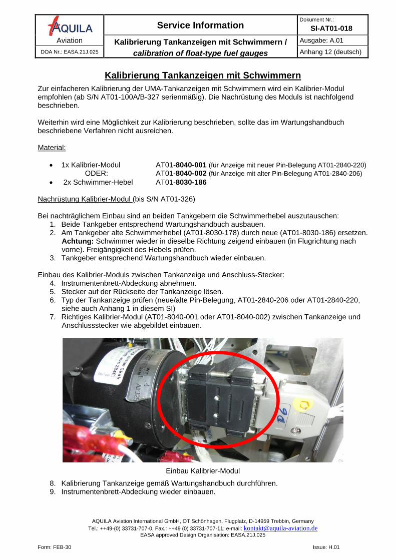
Zur einfacheren Kalibrierung der UMA-Tankanzeigen mit Schwimmern wird ein Kalibrier-Modul empfohlen (ab S/N AT01-100A/B-327 serienmäßig). Die Nachrüstung des Moduls ist nachfolgend beschrieben. Weiterhin wird eine Möglichkeit zur Kalibrierung beschrieben, sollte das im Wartungshandbuch beschriebene Verfahren nicht ausreichen. Material:
• 1x Kalibrier-Modul AT01-8040-001 (für Anzeige mit neuer Pin-Belegung AT01-2840-220) ODER: AT01-8040-002 (für Anzeige mit alter Pin-Belegung AT01-2840-206)
• 2x Schwimmer-Hebel AT01-8030-186
Nachrüstung Kalibrier-Modul (bis S/N AT01-326) Bei nachträglichem Einbau sind an beiden Tankgebern die Schwimmerhebel auszutauschen:
1. Beide Tankgeber entsprechend Wartungshandbuch ausbauen. 2. Am Tankgeber alte Schwimmerhebel (AT01-8030-178) durch neue (AT01-8030-186) ersetzen.
Achtung: Schwimmer wieder in dieselbe Richtung zeigend einbauen (in Flugrichtung nach vorne). Freigängigkeit des Hebels prüfen.
3. Tankgeber entsprechend Wartungshandbuch wieder einbauen. Einbau des Kalibrier-Moduls zwischen Tankanzeige und Anschluss-Stecker:
4. Instrumentenbrett-Abdeckung abnehmen. 5. Stecker auf der Rückseite der Tankanzeige lösen. 6. Typ der Tankanzeige prüfen (neue/alte Pin-Belegung, AT01-2840-206 oder AT01-2840-220,
siehe auch Anhang 1 in diesem SI) 7. Richtiges Kalibrier-Modul (AT01-8040-001 oder AT01-8040-002) zwischen Tankanzeige und
Anschlussstecker wie abgebildet einbauen.
Einbau Kalibrier-Modul
8. Kalibrierung Tankanzeige gemäß Wartungshandbuch durchführen. 9. Instrumentenbrett-Abdeckung wieder einbauen.
Service Information Dokument Nr.:
SI-AT01-018 Aviation Kalibrierung Tankanzeigen mit Schwimmern /
calibration of float-type fuel gauges
Ausgabe: A.01 DOA Nr.: EASA.21J.025 Anhang 12 (deutsch)
AQUILA Aviation International GmbH, OT Schönhagen, Flugplatz, D-14959 Trebbin, Germany Tel.: ++49-(0) 33731-707-0, Fax.: ++49 (0) 33731-707-11; e-mail: [email protected]
EASA approved Design Organisation: EASA.21J.025
Form: FEB-30 Issue: H.01
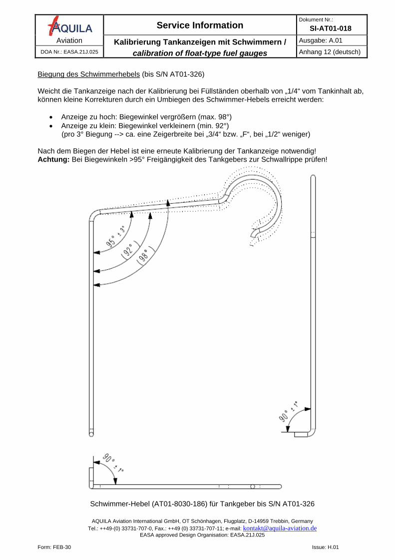
Biegung des Schwimmerhebels (bis S/N AT01-326) Weicht die Tankanzeige nach der Kalibrierung bei Füllständen oberhalb von „1/4“ vom Tankinhalt ab, können kleine Korrekturen durch ein Umbiegen des Schwimmer-Hebels erreicht werden:
• Anzeige zu hoch: Biegewinkel vergrößern (max. 98°) • Anzeige zu klein: Biegewinkel verkleinern (min. 92°)
(pro 3° Biegung --> ca. eine Zeigerbreite bei „3/4“ bzw. „F“, bei „1/2“ weniger) Nach dem Biegen der Hebel ist eine erneute Kalibrierung der Tankanzeige notwendig! Achtung: Bei Biegewinkeln >95° Freigängigkeit des Tankgebers zur Schwallrippe prüfen!
Schwimmer-Hebel (AT01-8030-186) für Tankgeber bis S/N AT01-326
Service Information Document No.:
SI-AT01-018 Aviation Kalibrierung Tankanzeigen mit Schwimmern /
calibration of float-type fuel gauges
Issue: A.01 DOA Nr.: EASA.21J.025 Annex 12 (english)
AQUILA Aviation International GmbH, OT Schönhagen, Flugplatz, D-14959 Trebbin, Germany Tel.: ++49-(0) 33731-707-0, Fax.: ++49 (0) 33731-707-11; e-mail: [email protected]
EASA approved Design Organisation: EASA.21J.025
Form: FEB-30 Issue: H.01
Calibration of float-type fuel gauges
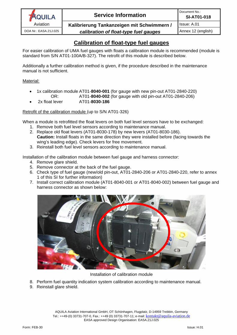
For easier calibration of UMA fuel gauges with floats a calibration module is recommended (module is standard from S/N AT01-100A/B-327). The retrofit of this module is described below. Additionally a further calibration method is given, if the procedure described in the maintenance manual is not sufficient. Material:
• 1x calibration module AT01-8040-001 (for gauge with new pin-out AT01-2840-220) OR: AT01-8040-002 (for gauge with old pin-out AT01-2840-206)
• 2x float lever AT01-8030-186
Retrofit of the calibration module (up to S/N AT01-326) When a module is retrofitted the float levers on both fuel level sensors have to be exchanged:
1. Remove both fuel level sensors according to maintenance manual. 2. Replace old float levers (AT01-8030-178) by new levers (AT01-8030-186).
Caution: Install floats in the same direction they were installed before (facing towards the wing’s leading edge). Check levers for free movement.
3. Reinstall both fuel level sensors according to maintenance manual. Installation of the calibration module between fuel gauge and harness connector:
4. Remove glare shield. 5. Remove connector at the back of the fuel gauge. 6. Check type of fuel gauge (new/old pin-out, AT01-2840-206 or AT01-2840-220, refer to annex
1 of this SI for further information) 7. Install correct calibration module (AT01-8040-001 or AT01-8040-002) between fuel gauge and
harness connector as shown below:
Installation of calibration module
8. Perform fuel quantity indication system calibration according to maintenance manual. 9. Reinstall glare shield.
Service Information Document No.:
SI-AT01-018 Aviation Kalibrierung Tankanzeigen mit Schwimmern /
calibration of float-type fuel gauges
Issue: A.01 DOA Nr.: EASA.21J.025 Annex 12 (english)
AQUILA Aviation International GmbH, OT Schönhagen, Flugplatz, D-14959 Trebbin, Germany Tel.: ++49-(0) 33731-707-0, Fax.: ++49 (0) 33731-707-11; e-mail: [email protected]
EASA approved Design Organisation: EASA.21J.025
Form: FEB-30 Issue: H.01
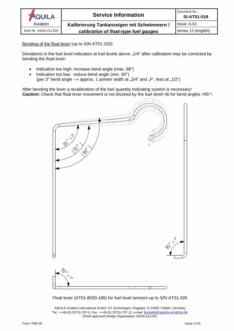
Bending of the float lever (up to S/N AT01-326) Deviations in the fuel level indication at fuel levels above „1/4“ after calibration may be corrected by bending the float lever:
• Indication too high: increase bend angle (max. 98°) • Indication too low: reduce bend angle (min. 92°)
(per 3° bend angle --> approx. 1 pointer width at „3/4“ and „F“, less at „1/2“) After bending the lever a recalibration of the fuel quantity indicating system is necessary! Caution: Check that float lever movement is not blocked by the fuel slosh rib for bend angles >95°!
Float lever (AT01-8030-186) for fuel level sensors up to S/N AT01-326
Service Information Dokument Nr.:
SI-AT01-018 Aviation PU-Schlauch Kühlmittelüberlauf, Cobra Schellen Ladedruck /
PU hose coolant overflow, Cobra clamps manifold pressure Ausgabe: A.01
DOA Nr.: EASA.21J.025 Anhang 13 (deutsch)
AQUILA Aviation International GmbH, OT Schönhagen, Flugplatz, D-14959 Trebbin, Germany Tel.: ++49-(0) 33731-707-0, Fax.: ++49 (0) 33731-707-11; e-mail: [email protected]
EASA approved Design Organisation: EASA.21J.025
Form: FEB-30 Issue: H.01
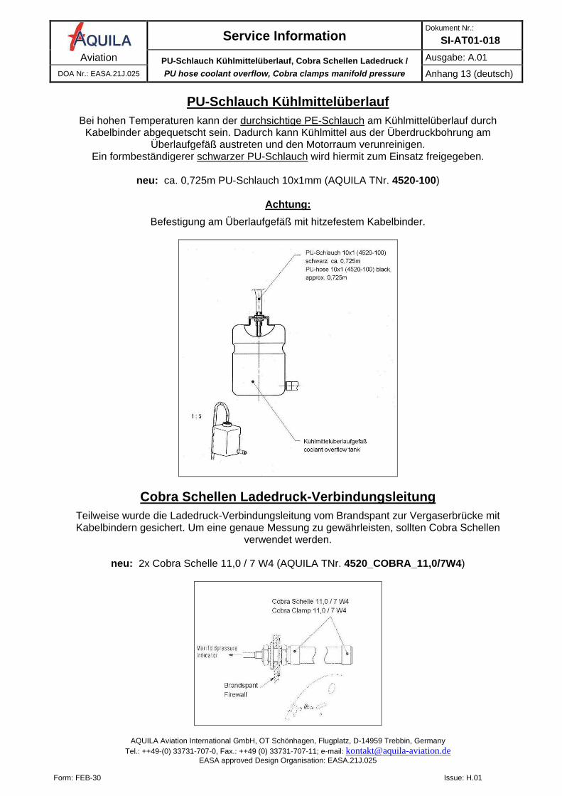
PU-Schlauch Kühlmittelüberlauf
Bei hohen Temperaturen kann der durchsichtige PE-Schlauch am Kühlmittelüberlauf durch Kabelbinder abgequetscht sein. Dadurch kann Kühlmittel aus der Überdruckbohrung am
Überlaufgefäß austreten und den Motorraum verunreinigen. Ein formbeständigerer schwarzer PU-Schlauch wird hiermit zum Einsatz freigegeben.
neu: ca. 0,725m PU-Schlauch 10x1mm (AQUILA TNr. 4520-100)
Achtung:
Befestigung am Überlaufgefäß mit hitzefestem Kabelbinder.
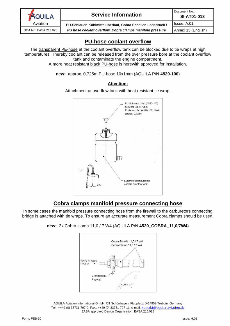
Cobra Schellen Ladedruck-Verbindungsleitung
Teilweise wurde die Ladedruck-Verbindungsleitung vom Brandspant zur Vergaserbrücke mit Kabelbindern gesichert. Um eine genaue Messung zu gewährleisten, sollten Cobra Schellen
verwendet werden.
neu: 2x Cobra Schelle 11,0 / 7 W4 (AQUILA TNr. 4520_COBRA_11,0/7W4)
Service Information Document No.:
SI-AT01-018 Aviation PU-Schlauch Kühlmittelüberlauf, Cobra Schellen Ladedruck /
PU hose coolant overflow, Cobra clamps manifold pressure Issue: A.01
DOA Nr.: EASA.21J.025 Annex 13 (English)
AQUILA Aviation International GmbH, OT Schönhagen, Flugplatz, D-14959 Trebbin, Germany Tel.: ++49-(0) 33731-707-0, Fax.: ++49 (0) 33731-707-11; e-mail: [email protected]
EASA approved Design Organisation: EASA.21J.025
Form: FEB-30 Issue: H.01
PU-hose coolant overflow
The transparent PE-hose at the coolant overflow tank can be blocked due to tie wraps at high temperatures. Thereby coolant can be released from the over pressure bore at the coolant overflow
tank and contaminate the engine compartment. A more heat resistant black PU-hose is herewith approved for installation.
new: approx. 0,725m PU-hose 10x1mm (AQUILA P/N 4520-100)
Attention:
Attachment at overflow tank with heat resistant tie wrap.
Cobra clamps manifold pressure connecting hose
In some cases the manifold pressure connecting hose from the firewall to the carburetors connecting bridge is attached with tie wraps. To ensure an accurate measurement Cobra clamps should be used.
new: 2x Cobra clamp 11,0 / 7 W4 (AQUILA P/N 4520_COBRA_11,0/7W4)
Service Information Document No.:
SI-AT01-018 Aviation Ersetzen von „Overlap“-Verbindern, Thermoleitungen /
Replacement of “Overlap Connectors”, thermocouple wires Issue: A.01
DOA Nr.: EASA.21J.025 Anhang 14 (deutsch)
AQUILA Aviation International GmbH, OT Schönhagen, Flugplatz, D-14959 Trebbin, Germany Tel.: ++49-(0) 33731-707-0, Fax.: ++49 (0) 33731-707-11; e-mail: [email protected]
EASA approved Design Organisation: EASA.21J.025
Form: FEB-30 Issue: H.01
Baureihe AT01-100C (mit MVP):
Ersetzen von „Overlap“-Verbindern, Thermoleitungen
Die Zuverlässigkeit der serienmäßigen „Overlap“-Verbinder wurde beanstandet. Es wird deshalb die korrekte Verwendung dieser Verbinder noch einmal beschrieben. Außerdem werden alternative Steckverbindungen freigegeben, die in der Wartung optional verwendet werden können und seit September 2015 serienmäßig
verbaut werden.
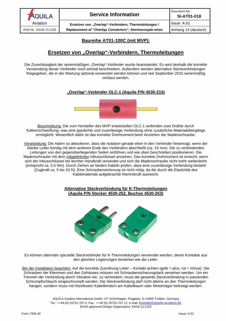
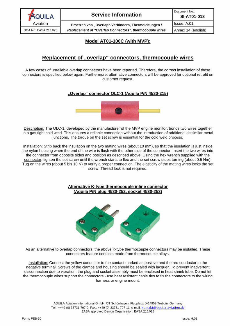
„Overlap“-Verbinder OLC-1 (Aquila P/N 4530-215)
Beschreibung: Die vom Hersteller des MVP entwickelten OLC-1 verbinden zwei Drähte durch Kaltverschweißung, was eine gasdichte und zuverlässige Verbindung ohne zusätzliche Materialübergänge
ermöglicht. Wesentlich dafür ist das korrekte Drehmoment beim Anziehen der Madenschraube.
Verarbeitung: Die Adern so abisolieren, dass die Isolation gerade eben in den Verbinder hineinragt, wenn der blanke Leiter bündig mit dem anderen Ende des Verbinders abschließt (ca. 10 mm). Die zu verbindenden
Leitungen von den gegenüberliegenden Seiten einführen und wie oben beschrieben positionieren. Die Madenschraube mit dem mitgelieferten Inbusschlüssel anziehen. Das korrekte Drehmoment ist erreicht, wenn sich der Inbusschlüssel bei leichter Handkraft verwindet und sich die Madenschraube nicht mehr weiterdreht (entspricht ca. 0,5 Nm). Durch Ziehen an beiden Kabeln prüfen, dass eine zuverlässige Verbindung besteht
(Zugkraft ca. 5 bis 10 N). Eine Schraubensicherung ist nicht nötig, da die durch die Elastizität des Kabelmaterials aufgebrachte Klemmkraft ausreicht.
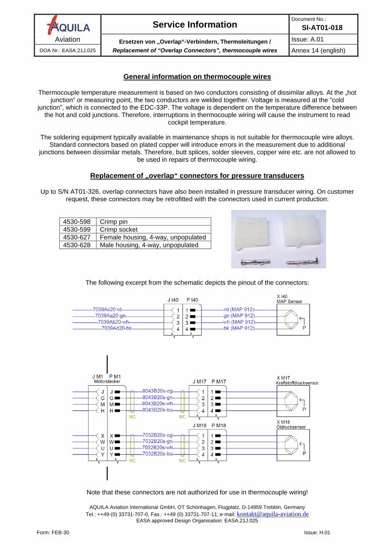
Alternative Steckverbindung für K-Thermoleitungen (Aquila P/N Stecker 4530-252, Buchse 4530-253)
Es können alternativ spezielle Steckverbinder für K-Thermoleitungen verwendet werden, deren Kontakte aus den gleichen Legierungen bestehen wie die Leiter.
Bei der Installation beachten: Auf die korrekte Zuordnung Leiter – Kontakt achten (gelb = plus, rot = minus). Die Schrauben der Klemmen und des Gehäuses müssen mit Schraubensicherungslack versehen werden. Um ein Trennen der Verbindung durch Vibration etc. zu verhindern, muss die gesamte Steckverbindung in passenden
Schrumpfschlauch eingeschrumpft werden. Die Steckverbindung darf nicht alleine an den Thermoleitungen hängen, sondern muss mit hitzefesten Kabelbindern am Kabelbaum oder Motorträger befestigt werden.
Service Information Document No.:
SI-AT01-018 Aviation Ersetzen von „Overlap“-Verbindern, Thermoleitungen /
Replacement of “Overlap Connectors”, thermocouple wires Issue: A.01
DOA Nr.: EASA.21J.025 Anhang 14 (deutsch)
AQUILA Aviation International GmbH, OT Schönhagen, Flugplatz, D-14959 Trebbin, Germany Tel.: ++49-(0) 33731-707-0, Fax.: ++49 (0) 33731-707-11; e-mail: [email protected]
EASA approved Design Organisation: EASA.21J.025
Form: FEB-30 Issue: H.01
Allgemeines zur Thermoleitungen
Die Temperaturmessung mit Thermoelementen basiert auf der Verwendung zweier Leiter aus unterschiedlichen Legierungen (z.B. NiCr und NiAl). An der Messstelle sind beide Leiter miteinander verschweißt. Ausgewertet wird die Spannung am Ende der Leiter, die von der Temperaturdifferenz zwischen Messstelle (Sensor) und Anschlusspunkt (EDC-33P) abhängt. Eine unterbrochene Thermoleitung führt daher zu einer Anzeige der
Cockpit-Temperatur.
Die in der Instandhaltung typischerweise verwendeten Lote sind nicht für die Legierungen der Ausgleichsleitungen geeignet. Herkömmliche Steckverbindungen können durch zusätzliche Materialübergänge
(z.B. Kupfer, Zinn) das Messergebnis verfälschen. Im Reparaturfall dürfen daher keine Crimpverbinder, Lötmuffen etc. verwendet werden. Die Reparatur / Verlängerung mit Kupferkabel ist nicht zulässig!
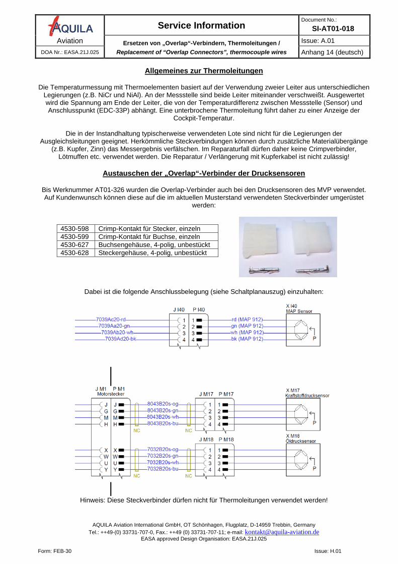
Austauschen der „Overlap“-Verbinder der Drucksensoren
Bis Werknummer AT01-326 wurden die Overlap-Verbinder auch bei den Drucksensoren des MVP verwendet. Auf Kundenwunsch können diese auf die im aktuellen Musterstand verwendeten Steckverbinder umgerüstet
werden:
4530-598 Crimp-Kontakt für Stecker, einzeln 4530-599 Crimp-Kontakt für Buchse, einzeln 4530-627 Buchsengehäuse, 4-polig, unbestückt 4530-628 Steckergehäuse, 4-polig, unbestückt
Dabei ist die folgende Anschlussbelegung (siehe Schaltplanauszug) einzuhalten:
Hinweis: Diese Steckverbinder dürfen nicht für Thermoleitungen verwendet werden!
Service Information Document No.:
SI-AT01-018 Aviation Ersetzen von „Overlap“-Verbindern, Thermoleitungen /
Replacement of “Overlap Connectors”, thermocouple wires Issue: A.01
DOA Nr.: EASA.21J.025 Annex 14 (english)
AQUILA Aviation International GmbH, OT Schönhagen, Flugplatz, D-14959 Trebbin, Germany Tel.: ++49-(0) 33731-707-0, Fax.: ++49 (0) 33731-707-11; e-mail: [email protected]
EASA approved Design Organisation: EASA.21J.025
Form: FEB-30 Issue: H.01
Model AT01-100C (with MVP):
Replacement of „overlap“ connectors, thermocouple wires
A few cases of unreliable overlap connectors have been reported. Therefore, the correct installation of these
connectors is specified below again. Furthermore, alternative connectors will be approved for optional retrofit on customer request.
„Overlap“ connector OLC-1 (Aquila P/N 4530-215)
Description: The OLC-1, developed by the manufacturer of the MVP engine monitor, bonds two wires together in a gas tight cold weld. This ensures a reliable connection without the introduction of additional dissimilar metal
junctions. The torque on the set screw is essential for the cold weld process.
Installation: Strip back the insulation on the two mating wires (about 10 mm), so that the insulation is just inside the nylon housing when the end of the wire is flush with the other side of the connector. Insert the two wires into
the connector from opposite sides and position as described above. Using the hex wrench supplied with the connector, tighten the set screw until the wrench starts to flex and the set screw stops turning (about 0.5 Nm).
Tug on the wires (about 5 bis 10 N) to verify a proper connection. The elasticity of the mating wires locks the set screw. Thread lock is not required.
Alternative K-type thermocouple inline connector (Aquila P/N plug 4530-252, socket 4530-253)
As an alternative to overlap connectors, the above K-type thermocouple connectors may be installed. These connectors feature contacts made from thermocouple alloys.
Installation: Connect the yellow conductor to the contact marked as positive and the red conductor to the
negative terminal. Screws of the clamps and housing should be sealed with lacquer. To prevent inadvertent disconnection due to vibration, the plug and socket assembly must be enclosed in heat shrink tube. Do not let
the thermocouple wires support the connectors - use heat resistant cable ties to fix the connectors to the wiring harness or engine mount.
Service Information Document No.:
SI-AT01-018 Aviation Ersetzen von „Overlap“-Verbindern, Thermoleitungen /
Replacement of “Overlap Connectors”, thermocouple wires Issue: A.01
DOA Nr.: EASA.21J.025 Annex 14 (english)
AQUILA Aviation International GmbH, OT Schönhagen, Flugplatz, D-14959 Trebbin, Germany Tel.: ++49-(0) 33731-707-0, Fax.: ++49 (0) 33731-707-11; e-mail: [email protected]
EASA approved Design Organisation: EASA.21J.025
Form: FEB-30 Issue: H.01
General information on thermocouple wires
Thermocouple temperature measurement is based on two conductors consisting of dissimilar alloys. At the „hot
junction“ or measuring point, the two conductors are welded together. Voltage is measured at the “cold junction”, which is connected to the EDC-33P. The voltage is dependent on the temperature difference between
the hot and cold junctions. Therefore, interruptions in thermocouple wiring will cause the instrument to read cockpit temperature.
The soldering equipment typically available in maintenance shops is not suitable for thermocouple wire alloys.
Standard connectors based on plated copper will introduce errors in the measurement due to additional junctions between dissimilar metals. Therefore, butt splices, solder sleeves, copper wire etc. are not allowed to
be used in repairs of thermocouple wiring.
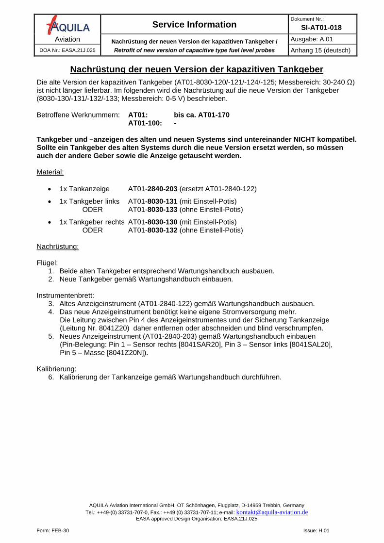
Replacement of „overlap“ connectors for pressure transducers
Up to S/N AT01-326, overlap connectors have also been installed in pressure transducer wiring. On customer request, these connectors may be retrofitted with the connectors used in current production:
4530-598 Crimp pin 4530-599 Crimp socket 4530-627 Female housing, 4-way, unpopulated 4530-628 Male housing, 4-way, unpopulated
The following excerpt from the schematic depicts the pinout of the connectors:
Note that these connectors are not authorized for use in thermocouple wiring!
Service Information Dokument Nr.:
SI-AT01-018 Aviation Nachrüstung der neuen Version der kapazitiven Tankgeber /
Retrofit of new version of capacitive type fuel level probes Ausgabe: A.01
DOA Nr.: EASA.21J.025 Anhang 15 (deutsch)
AQUILA Aviation International GmbH, OT Schönhagen, Flugplatz, D-14959 Trebbin, Germany Tel.: ++49-(0) 33731-707-0, Fax.: ++49 (0) 33731-707-11; e-mail: [email protected]
EASA approved Design Organisation: EASA.21J.025
Form: FEB-30 Issue: H.01
Nachrüstung der neuen Version der kapazitiven Tankgeber
Die alte Version der kapazitiven Tankgeber (AT01-8030-120/-121/-124/-125; Messbereich: 30-240 Ω) ist nicht länger lieferbar. Im folgenden wird die Nachrüstung auf die neue Version der Tankgeber (8030-130/-131/-132/-133; Messbereich: 0-5 V) beschrieben. Betroffene Werknummern: AT01: bis ca. AT01-170 AT01-100: - Tankgeber und –anzeigen des alten und neuen Systems sind untereinander NICHT kompatibel. Sollte ein Tankgeber des alten Systems durch die neue Version ersetzt werden, so müssen auch der andere Geber sowie die Anzeige getauscht werden. Material:
• 1x Tankanzeige AT01-2840-203 (ersetzt AT01-2840-122)
• 1x Tankgeber links AT01-8030-131 (mit Einstell-Potis) ODER AT01-8030-133 (ohne Einstell-Potis)
• 1x Tankgeber rechts AT01-8030-130 (mit Einstell-Potis) ODER AT01-8030-132 (ohne Einstell-Potis)
Nachrüstung: Flügel:
1. Beide alten Tankgeber entsprechend Wartungshandbuch ausbauen. 2. Neue Tankgeber gemäß Wartungshandbuch einbauen.
Instrumentenbrett:
3. Altes Anzeigeinstrument (AT01-2840-122) gemäß Wartungshandbuch ausbauen. 4. Das neue Anzeigeinstrument benötigt keine eigene Stromversorgung mehr.
Die Leitung zwischen Pin 4 des Anzeigeinstrumentes und der Sicherung Tankanzeige (Leitung Nr. 8041Z20) daher entfernen oder abschneiden und blind verschrumpfen.
5. Neues Anzeigeinstrument (AT01-2840-203) gemäß Wartungshandbuch einbauen (Pin-Belegung: Pin 1 – Sensor rechts [8041SAR20], Pin 3 – Sensor links [8041SAL20], Pin 5 – Masse [8041Z20N]).
Kalibrierung:
6. Kalibrierung der Tankanzeige gemäß Wartungshandbuch durchführen.
Service Information Document No.:
SI-AT01-018 Aviation Nachrüstung der neuen Version der kapazitiven Tankgeber /
Retrofit of new version of capacitive type fuel level probes Issue: A.01
DOA Nr.: EASA.21J.025 Annex 15 (english)
AQUILA Aviation International GmbH, OT Schönhagen, Flugplatz, D-14959 Trebbin, Germany Tel.: ++49-(0) 33731-707-0, Fax.: ++49 (0) 33731-707-11; e-mail: [email protected]
EASA approved Design Organisation: EASA.21J.025
Form: FEB-30 Issue: H.01
Retrofit of the new version of capacitive type fuel level probes The old version of capacitive type fuel level sensors (AT01-8030-120/-121/-124/-125; 30-240 Ω output) is no longer available. Instructions for a retrofit of the new version (8030-130/-131/-132/-133; 0-5 V output) are given below. Affected S/N: AT01: up to approx. AT01-170 AT01-100: - Fuel level sensors and indicators of the old and new system are NOT compatible to each other. If a sensor of the old system is replaced by the new version, the other sensor and the indicator have to be replaced as well. Material:
• 1x Indicator AT01-2840-203 (replaces AT01-2840-122)
• 1x Sensor LH AT01-8030-131 (with potentiometers for calibration) OR AT01-8030-133 (without potentiometers)
• 1x Sensor RH AT01-8030-130 (with potentiometers for calibration) OR AT01-8030-132 (without potentiometers)
Retrofit: Wing:
1. Remove both old fuel level sensors in accordance with maintenance manual. 2. Install new fuel level sensors in accordance with maintenance manual.
Instrument panel:
3. Remove old indicator (AT01-2840-122) in accordance with maintenance manual. 4. The new indicator needs no separate power supply. Therefore the power supply wire of the old
indicator ([8041Z20] from pin 4 of the indicator to the fuel gauge circuit breaker) is no longer needed. Remove or cut off and cover with heat shrink tubing.
5. Install new indicator (AT01-2840-203) in accordance with maintenance manual. (pin-assignment: pin 1 – RH sensor [8041SAR20], pin 3 – LH sensor [8041SAL20], pin 5 – ground [8041Z20N]).
Calibration:
6. Perform fuel quantity indication system calibration in accordance with maintenance manual.
Service Information Dokument Nr.:
SI-AT01-018 Aviation Nachrüstung Masseleitung Abgasendrohr /
Retrofit of bonding wire for exhaust pipe Ausgabe: A.01
DOA Nr.: EASA.21J.025 Anhang 16 (deutsch)
AQUILA Aviation International GmbH, OT Schönhagen, Flugplatz, D-14959 Trebbin, Germany Tel.: ++49-(0) 33731-707-0, Fax.: ++49 (0) 33731-707-11; e-mail: [email protected]
EASA approved Design Organisation: EASA.21J.025
Form: FEB-30 Issue: H.01
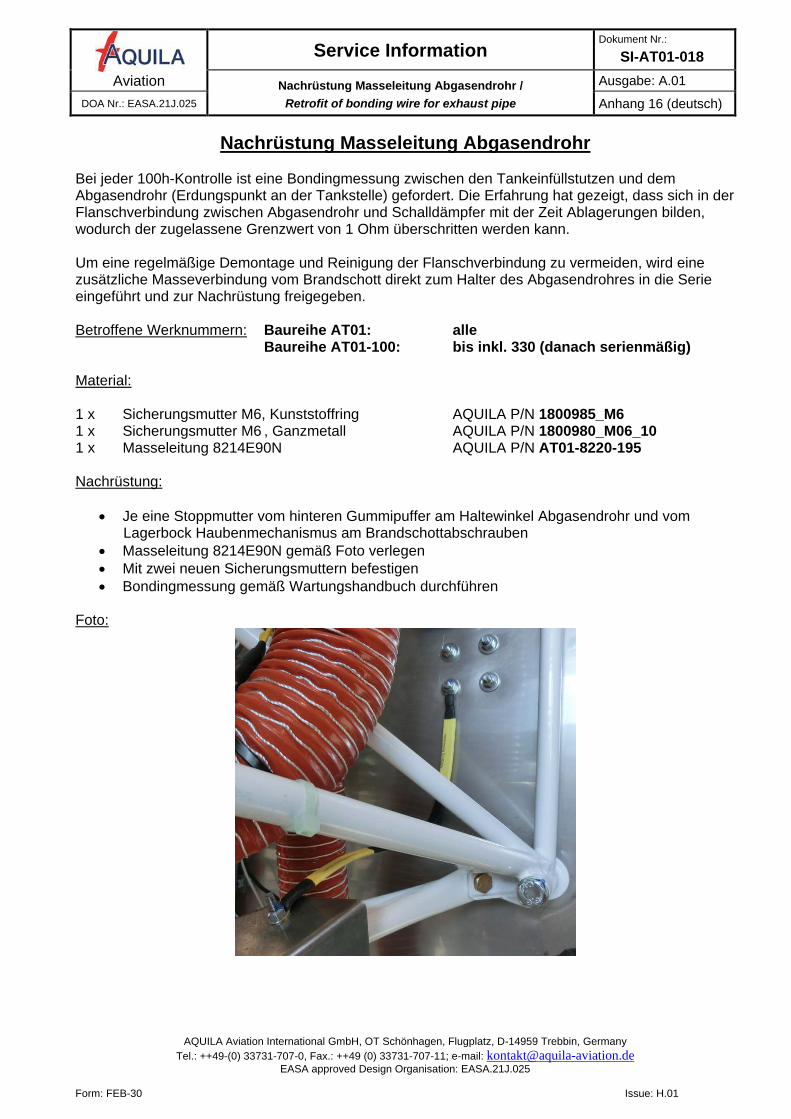
Nachrüstung Masseleitung Abgasendrohr Bei jeder 100h-Kontrolle ist eine Bondingmessung zwischen den Tankeinfüllstutzen und dem Abgasendrohr (Erdungspunkt an der Tankstelle) gefordert. Die Erfahrung hat gezeigt, dass sich in der Flanschverbindung zwischen Abgasendrohr und Schalldämpfer mit der Zeit Ablagerungen bilden, wodurch der zugelassene Grenzwert von 1 Ohm überschritten werden kann. Um eine regelmäßige Demontage und Reinigung der Flanschverbindung zu vermeiden, wird eine zusätzliche Masseverbindung vom Brandschott direkt zum Halter des Abgasendrohres in die Serie eingeführt und zur Nachrüstung freigegeben. Betroffene Werknummern: Baureihe AT01: alle Baureihe AT01-100: bis inkl. 330 (danach serienmäßig) Material: 1 x Sicherungsmutter M6, Kunststoffring AQUILA P/N 1800985_M6 1 x Sicherungsmutter M6 , Ganzmetall AQUILA P/N 1800980_M06_10 1 x Masseleitung 8214E90N AQUILA P/N AT01-8220-195 Nachrüstung:
• Je eine Stoppmutter vom hinteren Gummipuffer am Haltewinkel Abgasendrohr und vom Lagerbock Haubenmechanismus am Brandschottabschrauben
• Masseleitung 8214E90N gemäß Foto verlegen • Mit zwei neuen Sicherungsmuttern befestigen • Bondingmessung gemäß Wartungshandbuch durchführen
Foto:
Service Information Document No.:
SI-AT01-018 Aviation Nachrüstung Masseleitung Abgasendrohr /
Retrofit of bonding wire for exhaust pipe Issue: A.01
DOA Nr.: EASA.21J.025 Annex 16 (english)
AQUILA Aviation International GmbH, OT Schönhagen, Flugplatz, D-14959 Trebbin, Germany Tel.: ++49-(0) 33731-707-0, Fax.: ++49 (0) 33731-707-11; e-mail: [email protected]
EASA approved Design Organisation: EASA.21J.025
Form: FEB-30 Issue: H.01
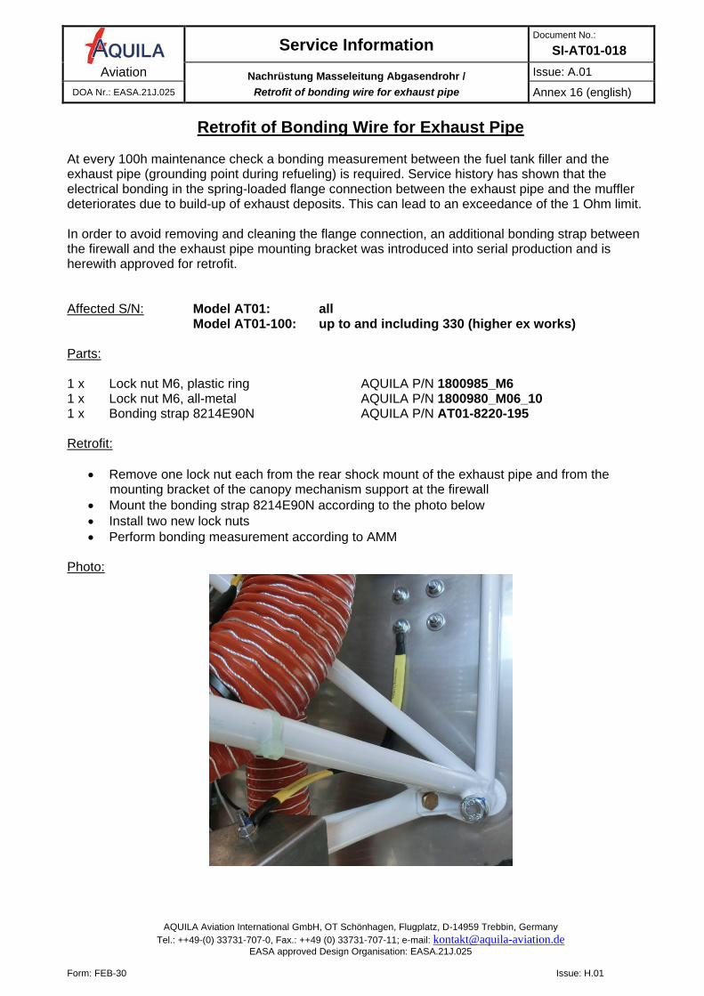
Retrofit of Bonding Wire for Exhaust Pipe At every 100h maintenance check a bonding measurement between the fuel tank filler and the exhaust pipe (grounding point during refueling) is required. Service history has shown that the electrical bonding in the spring-loaded flange connection between the exhaust pipe and the muffler deteriorates due to build-up of exhaust deposits. This can lead to an exceedance of the 1 Ohm limit. In order to avoid removing and cleaning the flange connection, an additional bonding strap between the firewall and the exhaust pipe mounting bracket was introduced into serial production and is herewith approved for retrofit. Affected S/N: Model AT01: all Model AT01-100: up to and including 330 (higher ex works) Parts: 1 x Lock nut M6, plastic ring AQUILA P/N 1800985_M6 1 x Lock nut M6, all-metal AQUILA P/N 1800980_M06_10 1 x Bonding strap 8214E90N AQUILA P/N AT01-8220-195 Retrofit:
• Remove one lock nut each from the rear shock mount of the exhaust pipe and from the mounting bracket of the canopy mechanism support at the firewall
• Mount the bonding strap 8214E90N according to the photo below • Install two new lock nuts • Perform bonding measurement according to AMM
Photo:
Service Information Dokument Nr.:
SI-AT01-018 Aviation Alternativer Feuerlöscher H3R A344T /
alternative fire extinguisher H3R A344T Ausgabe: A.01
DOA Nr.: EASA.21J.025 Anhang 17 (deutsch)
AQUILA Aviation International GmbH, OT Schönhagen, Flugplatz, D-14959 Trebbin, Germany Tel.: ++49-(0) 33731-707-0, Fax.: ++49 (0) 33731-707-11; e-mail: [email protected]
EASA approved Design Organisation: EASA.21J.025
Form: FEB-30 Issue: H.01
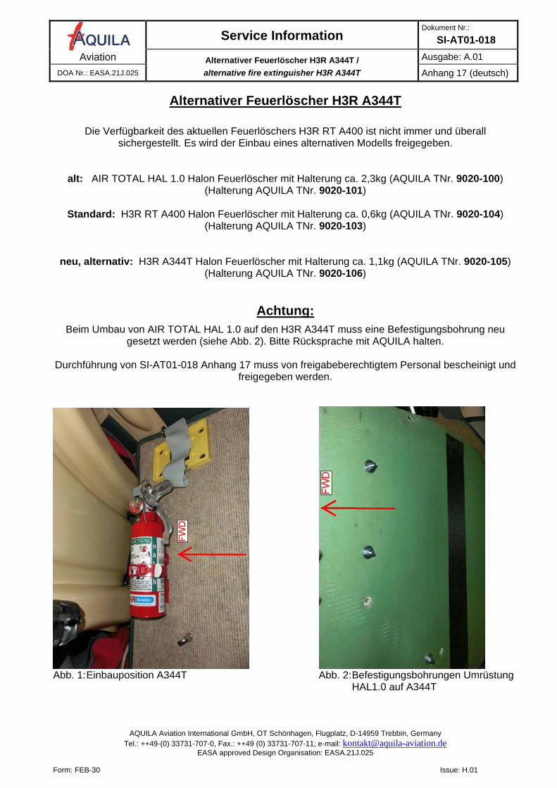
Alternativer Feuerlöscher H3R A344T
Die Verfügbarkeit des aktuellen Feuerlöschers H3R RT A400 ist nicht immer und überall
sichergestellt. Es wird der Einbau eines alternativen Modells freigegeben.
alt: AIR TOTAL HAL 1.0 Halon Feuerlöscher mit Halterung ca. 2,3kg (AQUILA TNr. 9020-100) (Halterung AQUILA TNr. 9020-101)
Standard: H3R RT A400 Halon Feuerlöscher mit Halterung ca. 0,6kg (AQUILA TNr. 9020-104)
(Halterung AQUILA TNr. 9020-103)
neu, alternativ: H3R A344T Halon Feuerlöscher mit Halterung ca. 1,1kg (AQUILA TNr. 9020-105) (Halterung AQUILA TNr. 9020-106)
Achtung:
Beim Umbau von AIR TOTAL HAL 1.0 auf den H3R A344T muss eine Befestigungsbohrung neu gesetzt werden (siehe Abb. 2). Bitte Rücksprache mit AQUILA halten.
Durchführung von SI-AT01-018 Anhang 17 muss von freigabeberechtigtem Personal bescheinigt und
freigegeben werden.
Abb. 1: Einbauposition A344T Abb. 2: Befestigungsbohrungen Umrüstung HAL1.0 auf A344T
Service Information Document No.:
SI-AT01-018 Aviation Alternativer Feuerlöscher H3R A344T /
alternative fire extinguisher H3R A344T Issue: A.01
DOA Nr.: EASA.21J.025 Annex 17 (english)
AQUILA Aviation International GmbH, OT Schönhagen, Flugplatz, D-14959 Trebbin, Germany Tel.: ++49-(0) 33731-707-0, Fax.: ++49 (0) 33731-707-11; e-mail: [email protected]
EASA approved Design Organisation: EASA.21J.025
Form: FEB-30 Issue: H.01
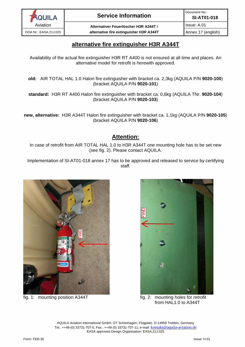
alternative fire extinguisher H3R A344T
Availability of the actual fire extinguisher H3R RT A400 is not ensured at all time and places. An
alternative model for retrofit is herewith approved.
old: AIR TOTAL HAL 1.0 Halon fire extinguisher with bracket ca. 2,3kg (AQUILA P/N 9020-100) (bracket AQUILA P/N 9020-101)
standard: H3R RT A400 Halon fire extinguisher with bracket ca. 0,6kg (AQUILA TNr. 9020-104)
(bracket AQUILA P/N 9020-103)
new, alternative: H3R A344T Halon fire extinguisher with bracket ca. 1,1kg (AQUILA P/N 9020-105) (bracket AQUILA P/N 9020-106)
Attention:
In case of retrofit from AIR TOTAL HAL 1.0 to H3R A344T one mounting hole has to be set new (see fig. 2). Please contact AQUILA.
Implementation of SI-AT01-018 annex 17 has to be approved and released to service by certifying
staff.
fig. 1: mounting position A344T fig. 2: mounting holes for retrofit from HAL1.0 to A344T
Service Information Dokument Nr.:
SI-AT01-018 Aviation ROTAX Ölkühler, neue Bauform /
ROTAX oil radiator, new design Ausgabe: A.01
DOA Nr.: EASA.21J.025 Anhang 18 (deutsch)
AQUILA Aviation International GmbH, OT Schönhagen, Flugplatz, D-14959 Trebbin, Germany Tel.: ++49-(0) 33731-707-0, Fax.: ++49 (0) 33731-707-11; e-mail: [email protected]
EASA approved Design Organisation: EASA.21J.025
Form: FEB-30 Issue: H.01
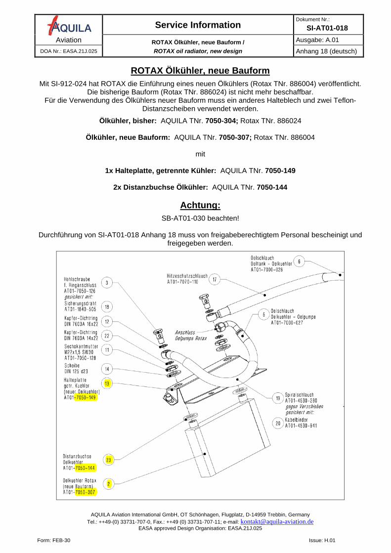
ROTAX Ölkühler, neue Bauform
Mit SI-912-024 hat ROTAX die Einführung eines neuen Ölkühlers (Rotax TNr. 886004) veröffentlicht. Die bisherige Bauform (Rotax TNr. 886024) ist nicht mehr beschaffbar.
Für die Verwendung des Ölkühlers neuer Bauform muss ein anderes Halteblech und zwei Teflon-Distanzscheiben verwendet werden.
Ölkühler, bisher: AQUILA TNr. 7050-304; Rotax TNr. 886024
Ölkühler, neue Bauform: AQUILA TNr. 7050-307; Rotax TNr. 886004
mit
1x Halteplatte, getrennte Kühler: AQUILA TNr. 7050-149
2x Distanzbuchse Ölkühler: AQUILA TNr. 7050-144
Achtung:
SB-AT01-030 beachten!
Durchführung von SI-AT01-018 Anhang 18 muss von freigabeberechtigtem Personal bescheinigt und freigegeben werden.
Service Information Document No.:
SI-AT01-018 Aviation ROTAX Ölkühler, neue Bauform /
ROTAX oil radiator, new design Issue: A.01
DOA Nr.: EASA.21J.025 Annex 18 (english)
AQUILA Aviation International GmbH, OT Schönhagen, Flugplatz, D-14959 Trebbin, Germany Tel.: ++49-(0) 33731-707-0, Fax.: ++49 (0) 33731-707-11; e-mail: [email protected]
EASA approved Design Organisation: EASA.21J.025
Form: FEB-30 Issue: H.01
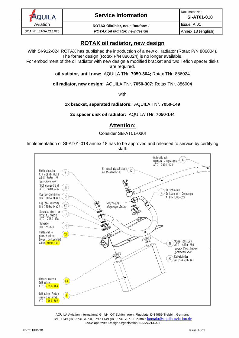
ROTAX oil radiator, new design
With SI-912-024 ROTAX has published the introduction of a new oil radiator (Rotax P/N 886004). The former design (Rotax P/N 886024) is no longer available.
For embodiment of the oil radiator with new design a modified bracket and two Teflon spacer disks are required.
oil radiator, until now: AQUILA TNr. 7050-304; Rotax TNr. 886024
oil radiator, new design: AQUILA TNr. 7050-307; Rotax TNr. 886004
with
1x bracket, separated radiators: AQUILA TNr. 7050-149
2x spacer disk oil radiator: AQUILA TNr. 7050-144
Attention:
Consider SB-AT01-030!
Implementation of SI-AT01-018 annex 18 has to be approved and released to service by certifying staff.
Service Information Dokument Nr.:
SI-AT01-018 Aviation Umrüstung von AVEO Andromeda auf Ultra Galactica /
retrofit from AVEO Andromeda to Ultra Galactica Ausgabe: A.01
DOA Nr.: EASA.21J.025 Anhang 19 (deutsch)
AQUILA Aviation International GmbH, OT Schönhagen, Flugplatz, D-14959 Trebbin, Germany Tel.: ++49-(0) 33731-707-0, Fax.: ++49 (0) 33731-707-11; e-mail: [email protected]
EASA approved Design Organisation: EASA.21J.025
Form: FEB-30 Issue: H.01
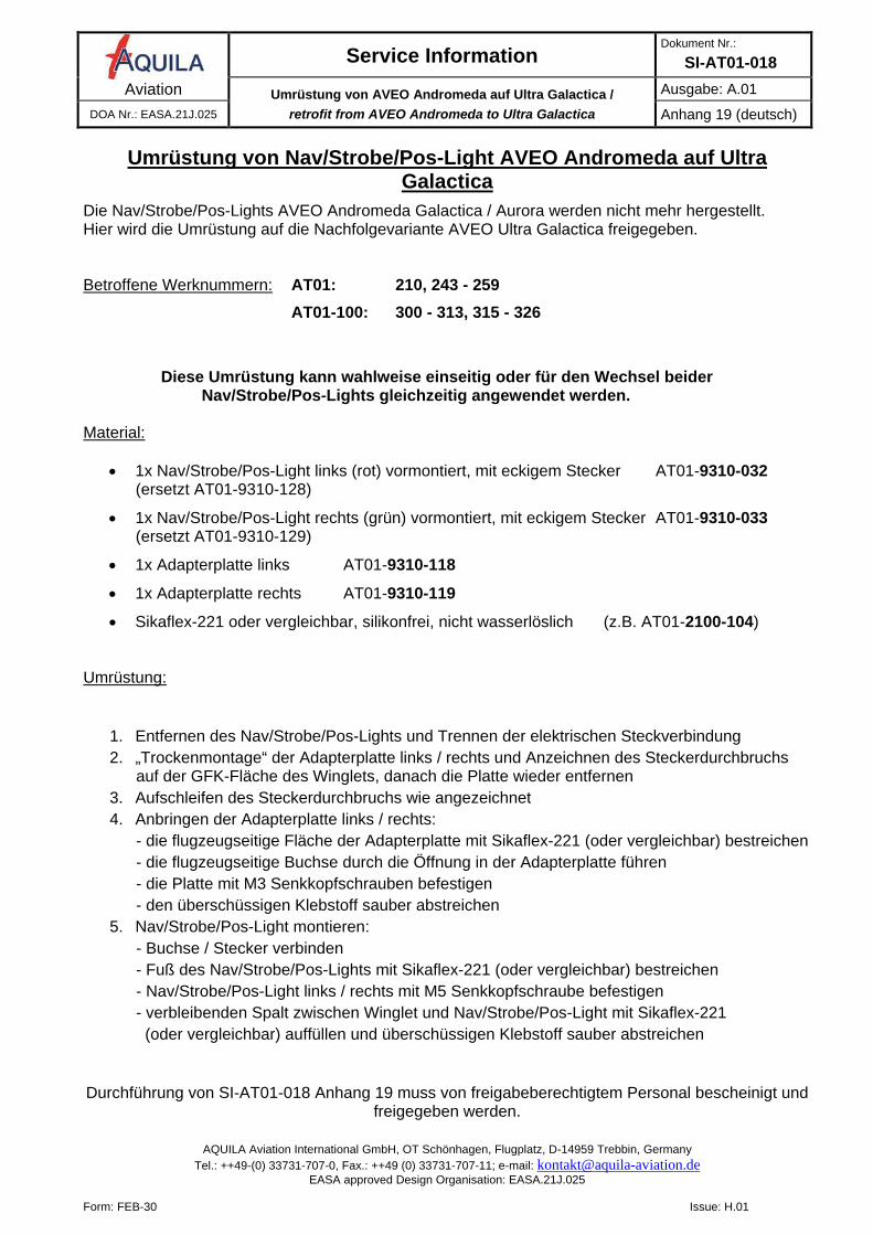
Umrüstung von Nav/Strobe/Pos-Light AVEO Andromeda auf Ultra Galactica
Die Nav/Strobe/Pos-Lights AVEO Andromeda Galactica / Aurora werden nicht mehr hergestellt. Hier wird die Umrüstung auf die Nachfolgevariante AVEO Ultra Galactica freigegeben. Betroffene Werknummern: AT01: 210, 243 - 259 AT01-100: 300 - 313, 315 - 326
Diese Umrüstung kann wahlweise einseitig oder für den Wechsel beider Nav/Strobe/Pos-Lights gleichzeitig angewendet werden.
Material:
• 1x Nav/Strobe/Pos-Light links (rot) vormontiert, mit eckigem Stecker AT01-9310-032 (ersetzt AT01-9310-128)
• 1x Nav/Strobe/Pos-Light rechts (grün) vormontiert, mit eckigem Stecker AT01-9310-033 (ersetzt AT01-9310-129)
• 1x Adapterplatte links AT01-9310-118
• 1x Adapterplatte rechts AT01-9310-119
• Sikaflex-221 oder vergleichbar, silikonfrei, nicht wasserlöslich (z.B. AT01-2100-104) Umrüstung:
1. Entfernen des Nav/Strobe/Pos-Lights und Trennen der elektrischen Steckverbindung 2. „Trockenmontage“ der Adapterplatte links / rechts und Anzeichnen des Steckerdurchbruchs
auf der GFK-Fläche des Winglets, danach die Platte wieder entfernen 3. Aufschleifen des Steckerdurchbruchs wie angezeichnet 4. Anbringen der Adapterplatte links / rechts:
- die flugzeugseitige Fläche der Adapterplatte mit Sikaflex-221 (oder vergleichbar) bestreichen - die flugzeugseitige Buchse durch die Öffnung in der Adapterplatte führen - die Platte mit M3 Senkkopfschrauben befestigen - den überschüssigen Klebstoff sauber abstreichen
5. Nav/Strobe/Pos-Light montieren: - Buchse / Stecker verbinden - Fuß des Nav/Strobe/Pos-Lights mit Sikaflex-221 (oder vergleichbar) bestreichen - Nav/Strobe/Pos-Light links / rechts mit M5 Senkkopfschraube befestigen - verbleibenden Spalt zwischen Winglet und Nav/Strobe/Pos-Light mit Sikaflex-221 (oder vergleichbar) auffüllen und überschüssigen Klebstoff sauber abstreichen
Durchführung von SI-AT01-018 Anhang 19 muss von freigabeberechtigtem Personal bescheinigt und
freigegeben werden.
Service Information Document No.:
SI-AT01-018 Aviation Umrüstung von AVEO Andromeda auf Ultra Galactica /
retrofit from AVEO Andromeda to Ultra Galactica Issue: A.01
DOA Nr.: EASA.21J.025 Annex 19 (english)
AQUILA Aviation International GmbH, OT Schönhagen, Flugplatz, D-14959 Trebbin, Germany Tel.: ++49-(0) 33731-707-0, Fax.: ++49 (0) 33731-707-11; e-mail: [email protected]
EASA approved Design Organisation: EASA.21J.025
Form: FEB-30 Issue: H.01
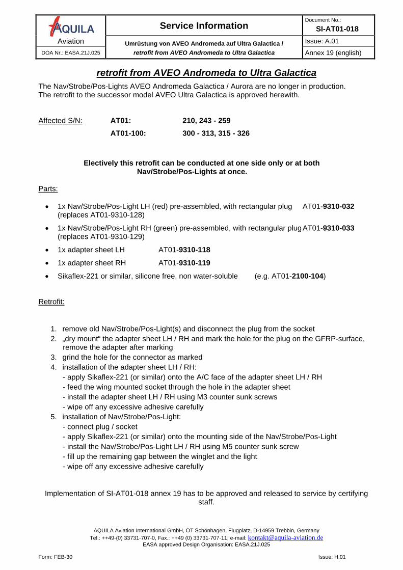
retrofit from AVEO Andromeda to Ultra Galactica
The Nav/Strobe/Pos-Lights AVEO Andromeda Galactica / Aurora are no longer in production. The retrofit to the successor model AVEO Ultra Galactica is approved herewith. Affected S/N: AT01: 210, 243 - 259 AT01-100: 300 - 313, 315 - 326
Electively this retrofit can be conducted at one side only or at both Nav/Strobe/Pos-Lights at once.
Parts: • 1x Nav/Strobe/Pos-Light LH (red) pre-assembled, with rectangular plug AT01-9310-032
(replaces AT01-9310-128)
• 1x Nav/Strobe/Pos-Light RH (green) pre-assembled, with rectangular plug AT01-9310-033 (replaces AT01-9310-129)
• 1x adapter sheet LH AT01-9310-118
• 1x adapter sheet RH AT01-9310-119
• Sikaflex-221 or similar, silicone free, non water-soluble (e.g. AT01-2100-104) Retrofit:
1. remove old Nav/Strobe/Pos-Light(s) and disconnect the plug from the socket 2. „dry mount“ the adapter sheet LH / RH and mark the hole for the plug on the GFRP-surface,
remove the adapter after marking 3. grind the hole for the connector as marked 4. installation of the adapter sheet LH / RH:
- apply Sikaflex-221 (or similar) onto the A/C face of the adapter sheet LH / RH - feed the wing mounted socket through the hole in the adapter sheet - install the adapter sheet LH / RH using M3 counter sunk screws - wipe off any excessive adhesive carefully
5. installation of Nav/Strobe/Pos-Light: - connect plug / socket - apply Sikaflex-221 (or similar) onto the mounting side of the Nav/Strobe/Pos-Light - install the Nav/Strobe/Pos-Light LH / RH using M5 counter sunk screw - fill up the remaining gap between the winglet and the light - wipe off any excessive adhesive carefully
Implementation of SI-AT01-018 annex 19 has to be approved and released to service by certifying staff.
Service Information Dokument Nr.:
SI-AT01-018 Aviation beheiztes Pitot mit Lemo Buchse /
heated Pitot with Lemo socket Ausgabe: A.02
DOA Nr.: EASA.21J.025 Anhang 20 (deutsch)
AQUILA Aviation International GmbH, OT Schönhagen, Flugplatz, D-14959 Trebbin, Germany Tel.: ++49-(0) 33731-707-0, Fax.: ++49 (0) 33731-707-11; e-mail: [email protected]
EASA approved Design Organisation: EASA.21J.025
Form: FEB-30 Issue: H.01
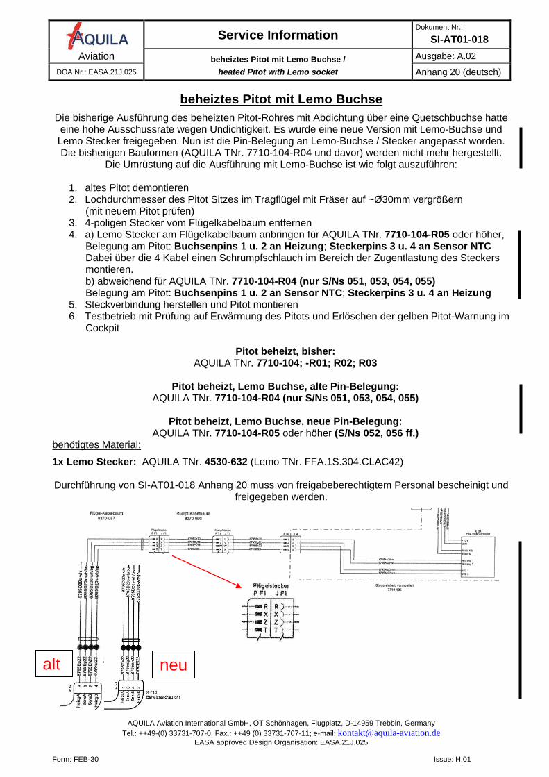
beheiztes Pitot mit Lemo Buchse
Die bisherige Ausführung des beheizten Pitot-Rohres mit Abdichtung über eine Quetschbuchse hatte eine hohe Ausschussrate wegen Undichtigkeit. Es wurde eine neue Version mit Lemo-Buchse und
Lemo Stecker freigegeben. Nun ist die Pin-Belegung an Lemo-Buchse / Stecker angepasst worden. Die bisherigen Bauformen (AQUILA TNr. 7710-104-R04 und davor) werden nicht mehr hergestellt.
Die Umrüstung auf die Ausführung mit Lemo-Buchse ist wie folgt auszuführen:
1. altes Pitot demontieren 2. Lochdurchmesser des Pitot Sitzes im Tragflügel mit Fräser auf ~Ø30mm vergrößern
(mit neuem Pitot prüfen) 3. 4-poligen Stecker vom Flügelkabelbaum entfernen 4. a) Lemo Stecker am Flügelkabelbaum anbringen für AQUILA TNr. 7710-104-R05 oder höher,
Belegung am Pitot: Buchsenpins 1 u. 2 an Heizung; Steckerpins 3 u. 4 an Sensor NTC Dabei über die 4 Kabel einen Schrumpfschlauch im Bereich der Zugentlastung des Steckers montieren. b) abweichend für AQUILA TNr. 7710-104-R04 (nur S/Ns 051, 053, 054, 055) Belegung am Pitot: Buchsenpins 1 u. 2 an Sensor NTC; Steckerpins 3 u. 4 an Heizung
5. Steckverbindung herstellen und Pitot montieren 6. Testbetrieb mit Prüfung auf Erwärmung des Pitots und Erlöschen der gelben Pitot-Warnung im
Cockpit
Pitot beheizt, bisher: AQUILA TNr. 7710-104; -R01; R02; R03
Pitot beheizt, Lemo Buchse, alte Pin-Belegung:
AQUILA TNr. 7710-104-R04 (nur S/Ns 051, 053, 054, 055)
Pitot beheizt, Lemo Buchse, neue Pin-Belegung: AQUILA TNr. 7710-104-R05 oder höher (S/Ns 052, 056 ff.)
benötigtes Material:
1x Lemo Stecker: AQUILA TNr. 4530-632 (Lemo TNr. FFA.1S.304.CLAC42)
Durchführung von SI-AT01-018 Anhang 20 muss von freigabeberechtigtem Personal bescheinigt und freigegeben werden.
alt neu
Service Information Dokument Nr.:
SI-AT01-018 Aviation beheiztes Pitot mit Lemo Buchse /
heated Pitot with Lemo socket Issue: A.02
DOA Nr.: EASA.21J.025 Anhang 20 (deutsch)
AQUILA Aviation International GmbH, OT Schönhagen, Flugplatz, D-14959 Trebbin, Germany Tel.: ++49-(0) 33731-707-0, Fax.: ++49 (0) 33731-707-11; e-mail: [email protected]
EASA approved Design Organisation: EASA.21J.025
Form: FEB-30 Issue: H.01
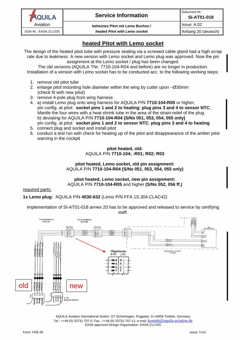
heated Pitot with Lemo socket
The design of the heated pitot tube with pressure sealing via a screwed cable gland had a high scrap rate due to leakiness. A new version with Lemo socket and Lemo plug was approved. Now the pin
assignment at the Lemo socket / plug has been changed. The old versions (AQUILA TNr. 7710-104-R04 and before) are no longer in production.
Installation of a version with Lemo socket has to be conducted acc. to the following working steps:
1. remove old pitot tube 2. enlarge pitot mounting hole diameter within the wing by cutter upon ~Ø30mm
(check fit with new pitot) 3. remove 4-pole plug from wing harness 4. a) install Lemo plug onto wing harness for AQUILA P/N 7710-104-R05 or higher,
pin config. at pitot: socket pins 1 and 2 to heating; plug pins 3 and 4 to sensor NTC; Mantle the four wires with a heat shrink tube in the area of the strain-relief of the plug. b) deviating for AQUILA P/N 7710-104-R04 (S/Ns 051, 053, 054, 055 only) pin config. at pitot: socket pins 1 and 2 to sensor NTC; plug pins 3 and 4 to heating
5. connect plug and socket and install pitot 6. conduct a test run with check for heating up of the pitot and disappearance of the amber pitot
warning in the cockpit
pitot heated, old: AQUILA P/N 7710-104; -R01; R02; R03
pitot heated, Lemo socket, old pin assignment:
AQUILA P/N 7710-104-R04 (S/Ns 051, 053, 054, 055 only)
pitot heated, Lemo socket, new pin assignment: AQUILA P/N 7710-104-R05 and higher (S/Ns 052, 056 ff.)
required parts:
1x Lemo plug: AQUILA P/N 4530-632 (Lemo P/N FFA.1S.304.CLAC42)
Implementation of SI-AT01-018 annex 20 has to be approved and released to service by certifying staff.
old new
Service Information Dokument Nr.:
SI-AT01-018 Aviation Spacer am Halteblech Endrohr /
spacer at bracket for exhaust tail pipe Issue: A.01
DOA Nr.: EASA.21J.025 Anhang 21 (deutsch)
AQUILA Aviation International GmbH, OT Schönhagen, Flugplatz, D-14959 Trebbin, Germany Tel.: ++49-(0) 33731-707-0, Fax.: ++49 (0) 33731-707-11; e-mail: [email protected]
EASA approved Design Organisation: EASA.21J.025
Form: FEB-30 Issue: H.01
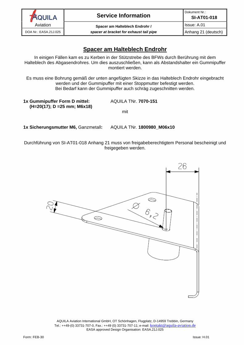
Spacer am Halteblech Endrohr
In einigen Fällen kam es zu Kerben in der Stützstrebe des BFWs durch Berührung mit dem Halteblech des Abgasendrohres. Um dies auszuschließen, kann als Abstandshalter ein Gummipuffer
montiert werden.
Es muss eine Bohrung gemäß der unten angefügten Skizze in das Halteblech Endrohr eingebracht werden und der Gummipuffer mit einer Stoppmutter befestigt werden. Bei Bedarf kann der Gummipuffer auch schräg zugeschnitten werden.
1x Gummipuffer Form D mittel: AQUILA TNr. 7070-151 (H=20(17); D =25 mm; M6x18)
mit
1x Sicherungsmutter M6, Ganzmetall: AQUILA TNr. 1800980_M06x10
Durchführung von SI-AT01-018 Anhang 21 muss von freigabeberechtigtem Personal bescheinigt und freigegeben werden.
Service Information Document No.:
SI-AT01-018 Aviation Spacer am Halteblech Endrohr /
spacer at bracket for exhaust tail pipe Issue: A.01
DOA Nr.: EASA.21J.025 Annex 21 (english)
AQUILA Aviation International GmbH, OT Schönhagen, Flugplatz, D-14959 Trebbin, Germany Tel.: ++49-(0) 33731-707-0, Fax.: ++49 (0) 33731-707-11; e-mail: [email protected]
EASA approved Design Organisation: EASA.21J.025
Form: FEB-30 Issue: H.01
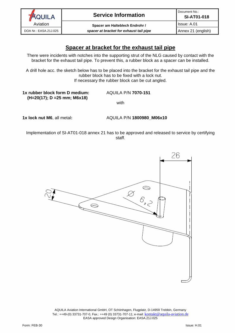
Spacer at bracket for the exhaust tail pipe
There were incidents with notches into the supporting strut of the NLG caused by contact with the bracket for the exhaust tail pipe. To prevent this, a rubber block as a spacer can be installed.
A drill hole acc. the sketch below has to be placed into the bracket for the exhaust tail pipe and the
rubber block has to be fixed with a lock nut. If necessary the rubber block can be cut angled.
1x rubber block form D medium: AQUILA P/N 7070-151 (H=20(17); D =25 mm; M6x18)
with
1x lock nut M6, all metal: AQUILA P/N 1800980_M06x10
Implementation of SI-AT01-018 annex 21 has to be approved and released to service by certifying staff.
Service Information Dokument Nr.:
SI-AT01-018 Aviation neue Beringer Felgen und Reifen /
new Beringer wheels and tires Issue: A.01
DOA Nr.: EASA.21J.025 Anhang 22 (deutsch)
AQUILA Aviation International GmbH, OT Schönhagen, Flugplatz, D-14959 Trebbin, Germany Tel.: ++49-(0) 33731-707-0, Fax.: ++49 (0) 33731-707-11; e-mail: [email protected]
EASA approved Design Organisation: EASA.21J.025
Form: FEB-30 Issue: H.01
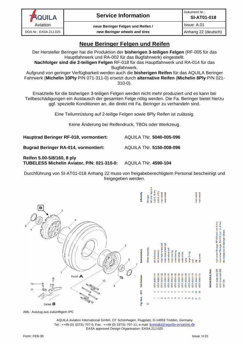
Neue Beringer Felgen und Reifen
Der Hersteller Beringer hat die Produktion der bisherigen 3-teiligen Felgen (RF-005 für das Hauptfahrwerk und RA-002 für das Bugfahrwerk) eingestellt.
Nachfolger sind die 2-teiligen Felgen RF-018 für das Hauptfahrwerk und RA-014 für das Bugfahrwerk.
Aufgrund von geringer Verfügbarkeit werden auch die bisherigen Reifen für das AQUILA Beringer Fahrwerk (Michelin 10Ply P/N 071-311-0) ersetzt durch alternative Reifen (Michelin 8Ply P/N 021-
310-0).
Ersatzteile für die bisherigen 3-teiligen Felgen werden nicht mehr produziert und es kann bei Teilbeschädigungen ein Austausch der gesamten Felge nötig werden. Die Fa. Beringer bietet hierzu
ggf. spezielle Konditionen an, die direkt mit Fa. Beringer zu verhandeln sind.
Eine Teilumrüstung auf 2-teilige Felgen sowie 8Ply Reifen ist zulässig.
Keine Änderung bei Reifendruck, TBOs oder Werkzeug.
Hauptrad Beringer RF-018, vormontiert: AQUILA TNr. 5040-005-096 Bugrad Beringer RA-014, vormontiert: AQUILA TNr. 5150-008-096
Reifen 5.00-5/8/160, 8 ply TUBELESS Michelin Aviator, P/N: 021-310-0: AQUILA TNr. 4590-104
Durchführung von SI-AT01-018 Anhang 22 muss von freigabeberechtigtem Personal bescheinigt und
freigegeben werden.
Abb.: Auszug aus zukünftigem IPC
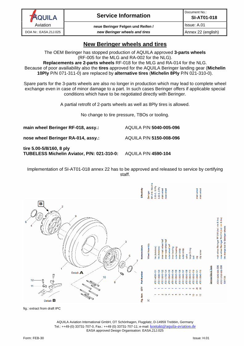
Service Information Document No.:
SI-AT01-018 Aviation neue Beringer Felgen und Reifen /
new Beringer wheels and tires Issue: A.01
DOA Nr.: EASA.21J.025 Annex 22 (english)
AQUILA Aviation International GmbH, OT Schönhagen, Flugplatz, D-14959 Trebbin, Germany Tel.: ++49-(0) 33731-707-0, Fax.: ++49 (0) 33731-707-11; e-mail: [email protected]
EASA approved Design Organisation: EASA.21J.025
Form: FEB-30 Issue: H.01
New Beringer wheels and tires
The OEM Beringer has stopped production of AQUILA approved 3-parts wheels (RF-005 for the MLG and RA-002 for the NLG).
Replacements are 2-parts wheels RF-018 for the MLG and RA-014 for the NLG. Because of poor availiability also the tires approved for the AQUILA Beringer landing gear (Michelin
10Ply P/N 071-311-0) are replaced by alternative tires (Michelin 8Ply P/N 021-310-0).
Spare parts for the 3-parts wheels are also no longer in production which may lead to complete wheel exchange even in case of minor damage to a part. In such cases Beringer offers if applicable special
conditions which have to be negotiated directly with Beringer.
A partial retrofit of 2-parts wheels as well as 8Ply tires is allowed.
No change to tire pressure, TBOs or tooling.
main wheel Beringer RF-018, assy.: AQUILA P/N 5040-005-096 nose wheel Beringer RA-014, assy.: AQUILA P/N 5150-008-096 tire 5.00-5/8/160, 8 ply TUBELESS Michelin Aviator, P/N: 021-310-0: AQUILA P/N 4590-104
Implementation of SI-AT01-018 annex 22 has to be approved and released to service by certifying staff.
fig.: extract from draft IPC
Related Documents