339-0089-000 ISSUED 02/2010 Please record the following data for file reference Tag Number(s): ________________________________ Model Number: ________________________________ Serial Number: ________________________________ Installation Date: ______________________________ Installation Location: ___________________________ INSTALLATION, OPERATION, AND MAINTENANCE MANUAL Series G Model G METERING PUMP

Welcome message from author
This document is posted to help you gain knowledge. Please leave a comment to let me know what you think about it! Share it to your friends and learn new things together.
Transcript
339-0089-000 ISSUED 02/2010
Please record the following data for file referenceTag Number(s): ________________________________Model Number: ________________________________Serial Number: ________________________________Installation Date: ______________________________Installation Location: ___________________________
INSTALLATION,OPERATION, ANDMAINTENANCEMANUAL
Series G Model GMETERINGPUMP
i
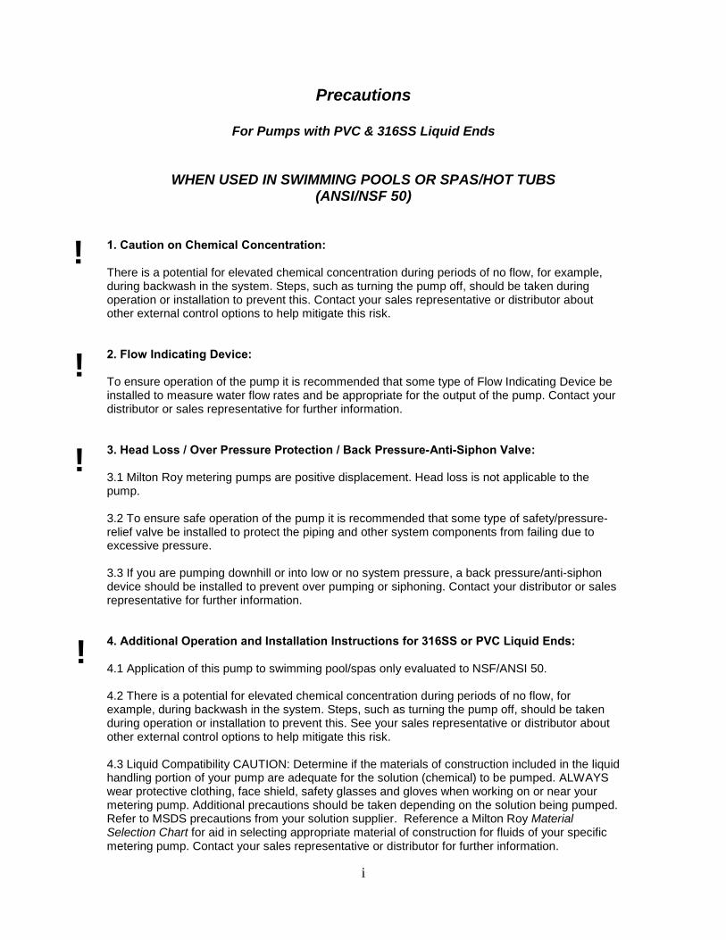
Precautions
For Pumps with PVC & 316SS Liquid Ends
WHEN USED IN SWIMMING POOLS OR SPAS/HOT TUBS (ANSI/NSF 50)
1. Caution on Chemical Concentration: There is a potential for elevated chemical concentration during periods of no flow, for example, during backwash in the system. Steps, such as turning the pump off, should be taken during operation or installation to prevent this. Contact your sales representative or distributor about other external control options to help mitigate this risk.
2. Flow Indicating Device: To ensure operation of the pump it is recommended that some type of Flow Indicating Device be installed to measure water flow rates and be appropriate for the output of the pump. Contact your distributor or sales representative for further information. 3. Head Loss / Over Pressure Protection / Back Pressure-Anti-Siphon Valve: 3.1 Milton Roy metering pumps are positive displacement. Head loss is not applicable to the pump. 3.2 To ensure safe operation of the pump it is recommended that some type of safety/pressure-relief valve be installed to protect the piping and other system components from failing due to excessive pressure. 3.3 If you are pumping downhill or into low or no system pressure, a back pressure/anti-siphon device should be installed to prevent over pumping or siphoning. Contact your distributor or sales representative for further information. 4. Additional Operation and Installation Instructions for 316SS or PVC Liquid Ends: 4.1 Application of this pump to swimming pool/spas only evaluated to NSF/ANSI 50. 4.2 There is a potential for elevated chemical concentration during periods of no flow, for example, during backwash in the system. Steps, such as turning the pump off, should be taken during operation or installation to prevent this. See your sales representative or distributor about other external control options to help mitigate this risk. 4.3 Liquid Compatibility CAUTION: Determine if the materials of construction included in the liquid handling portion of your pump are adequate for the solution (chemical) to be pumped. ALWAYS wear protective clothing, face shield, safety glasses and gloves when working on or near your metering pump. Additional precautions should be taken depending on the solution being pumped. Refer to MSDS precautions from your solution supplier. Reference a Milton Roy Material Selection Chart for aid in selecting appropriate material of construction for fluids of your specific metering pump. Contact your sales representative or distributor for further information.
!
!
!
!
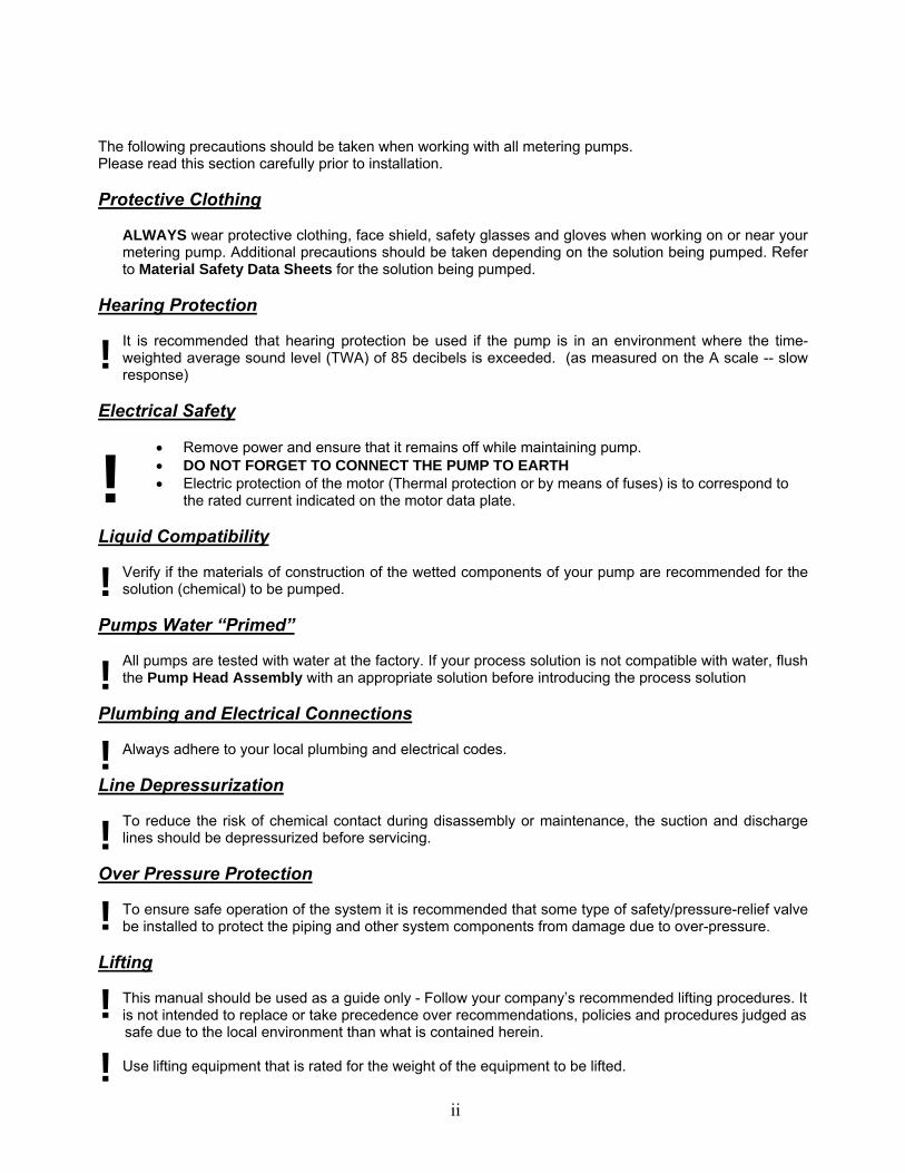
The following precautions should be taken when working with all metering pumps. Please read this section carefully prior to installation. Protective Clothing
ALWAYS wear protective clothing, face shield, safety glasses and gloves when working on or near your metering pump. Additional precautions should be taken depending on the solution being pumped. Refer to Material Safety Data Sheets for the solution being pumped.
Hearing Protection
! It is recommended that hearing protection be used if the pump is in an environment where the time-weighted average sound level (TWA) of 85 decibels is exceeded. (as measured on the A scale -- slow response)
Electrical Safety
!
• Remove power and ensure that it remains off while maintaining pump. • DO NOT FORGET TO CONNECT THE PUMP TO EARTH • Electric protection of the motor (Thermal protection or by means of fuses) is to correspond to
the rated current indicated on the motor data plate.
Liquid Compatibility
!
Verify if the materials of construction of the wetted components of your pump are recommended for the solution (chemical) to be pumped.
Pumps Water “Primed”
!
All pumps are tested with water at the factory. If your process solution is not compatible with water, flush the Pump Head Assembly with an appropriate solution before introducing the process solution
Plumbing and Electrical Connections
! Always adhere to your local plumbing and electrical codes.
Line Depressurization
!
To reduce the risk of chemical contact during disassembly or maintenance, the suction and discharge lines should be depressurized before servicing.
Over Pressure Protection
! To ensure safe operation of the system it is recommended that some type of safety/pressure-relief valve be installed to protect the piping and other system components from damage due to over-pressure.
Lifting
! This manual should be used as a guide only - Follow your company’s recommended lifting procedures. It is not intended to replace or take precedence over recommendations, policies and procedures judged as safe due to the local environment than what is contained herein.
! Use lifting equipment that is rated for the weight of the equipment to be lifted.
ii
jmiller
Typewritten Text
General Precautions For All Pumps
jmiller
Typewritten Text
jmiller
Typewritten Text
jmiller
Typewritten Text
jmiller
Typewritten Text
iii
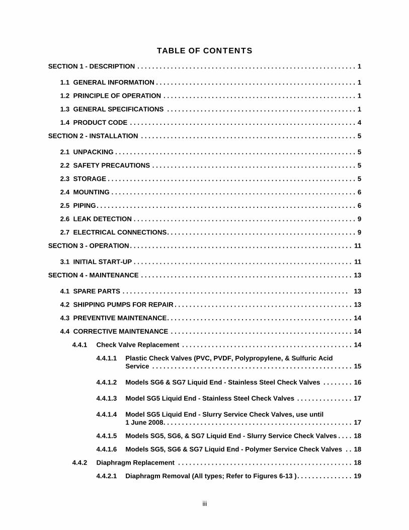
TABLE OF CONTENTS
SECTION 1 - DESCRIPTION . . . . . . . . . . . . . . . . . . . . . . . . . . . . . . . . . . . . . . . . . . . . . . . . . . . . . . . . . . . 1
1.1 GENERAL INFORMATION . . . . . . . . . . . . . . . . . . . . . . . . . . . . . . . . . . . . . . . . . . . . . . . . . . . . . . 1
1.2 PRINCIPLE OF OPERATION . . . . . . . . . . . . . . . . . . . . . . . . . . . . . . . . . . . . . . . . . . . . . . . . . . . . 1
1.3 GENERAL SPECIFICATIONS . . . . . . . . . . . . . . . . . . . . . . . . . . . . . . . . . . . . . . . . . . . . . . . . . . . 1
1.4 PRODUCT CODE . . . . . . . . . . . . . . . . . . . . . . . . . . . . . . . . . . . . . . . . . . . . . . . . . . . . . . . . . . . . . 4
SECTION 2 - INSTALLATION . . . . . . . . . . . . . . . . . . . . . . . . . . . . . . . . . . . . . . . . . . . . . . . . . . . . . . . . . . 5
2.1 UNPACKING . . . . . . . . . . . . . . . . . . . . . . . . . . . . . . . . . . . . . . . . . . . . . . . . . . . . . . . . . . . . . . . . . 5
2.2 SAFETY PRECAUTIONS . . . . . . . . . . . . . . . . . . . . . . . . . . . . . . . . . . . . . . . . . . . . . . . . . . . . . . . 5
2.3 STORAGE . . . . . . . . . . . . . . . . . . . . . . . . . . . . . . . . . . . . . . . . . . . . . . . . . . . . . . . . . . . . . . . . . . . 5
2.4 MOUNTING . . . . . . . . . . . . . . . . . . . . . . . . . . . . . . . . . . . . . . . . . . . . . . . . . . . . . . . . . . . . . . . . . . 6
2.5 PIPING. . . . . . . . . . . . . . . . . . . . . . . . . . . . . . . . . . . . . . . . . . . . . . . . . . . . . . . . . . . . . . . . . . . . . . 6
2.6 LEAK DETECTION . . . . . . . . . . . . . . . . . . . . . . . . . . . . . . . . . . . . . . . . . . . . . . . . . . . . . . . . . . . . 9
2.7 ELECTRICAL CONNECTIONS. . . . . . . . . . . . . . . . . . . . . . . . . . . . . . . . . . . . . . . . . . . . . . . . . . . 9
SECTION 3 - OPERATION . . . . . . . . . . . . . . . . . . . . . . . . . . . . . . . . . . . . . . . . . . . . . . . . . . . . . . . . . . . . 11
3.1 INITIAL START-UP . . . . . . . . . . . . . . . . . . . . . . . . . . . . . . . . . . . . . . . . . . . . . . . . . . . . . . . . . . . 11
SECTION 4 - MAINTENANCE . . . . . . . . . . . . . . . . . . . . . . . . . . . . . . . . . . . . . . . . . . . . . . . . . . . . . . . . . 13
4.1 SPARE PARTS . . . . . . . . . . . . . . . . . . . . . . . . . . . . . . . . . . . . . . . . . . . . . . . . . . . . . . . . . . . . . 13
4.2 SHIPPING PUMPS FOR REPAIR . . . . . . . . . . . . . . . . . . . . . . . . . . . . . . . . . . . . . . . . . . . . . . . . 13
4.3 PREVENTIVE MAINTENANCE. . . . . . . . . . . . . . . . . . . . . . . . . . . . . . . . . . . . . . . . . . . . . . . . . . 14
4.4 CORRECTIVE MAINTENANCE . . . . . . . . . . . . . . . . . . . . . . . . . . . . . . . . . . . . . . . . . . . . . . . . . 14
4.4.1 Check Valve Replacement . . . . . . . . . . . . . . . . . . . . . . . . . . . . . . . . . . . . . . . . . . . . . . 14
4.4.1.1 Plastic Check Valves (PVC, PVDF, Polypropylene, & Sulfuric Acid Service . . . . . . . . . . . . . . . . . . . . . . . . . . . . . . . . . . . . . . . . . . . . . . . . . . . . . . 15
4.4.1.2 Models SG6 & SG7 Liquid End - Stainless Steel Check Valves . . . . . . . . 16
4.4.1.3 Model SG5 Liquid End - Stainless Steel Check Valves . . . . . . . . . . . . . . . 17
4.4.1.4 Model SG5 Liquid End - Slurry Service Check Valves, use until1 June 2008. . . . . . . . . . . . . . . . . . . . . . . . . . . . . . . . . . . . . . . . . . . . . . . . . . . 17
4.4.1.5 Models SG5, SG6, & SG7 Liquid End - Slurry Service Check Valves . . . . 18
4.4.1.6 Models SG5, SG6 & SG7 Liquid End - Polymer Service Check Valves . . 18
4.4.2 Diaphragm Replacement . . . . . . . . . . . . . . . . . . . . . . . . . . . . . . . . . . . . . . . . . . . . . . . 18
4.4.2.1 Diaphragm Removal (All types; Refer to Figures 6-13 ) . . . . . . . . . . . . . . . 19
iv
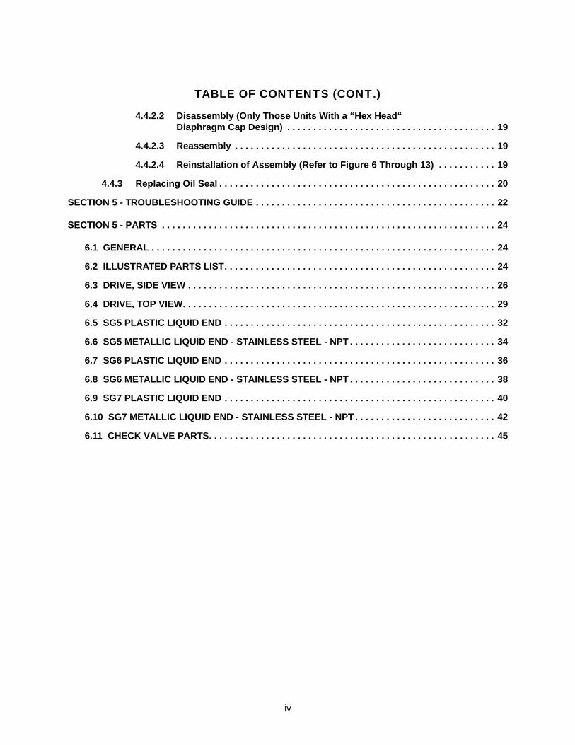
TABLE OF CONTENTS (CONT.)
4.4.2.2 Disassembly (Only Those Units With a “Hex Head“ Diaphragm Cap Design) . . . . . . . . . . . . . . . . . . . . . . . . . . . . . . . . . . . . . . . . 19
4.4.2.3 Reassembly . . . . . . . . . . . . . . . . . . . . . . . . . . . . . . . . . . . . . . . . . . . . . . . . . . 19
4.4.2.4 Reinstallation of Assembly (Refer to Figure 6 Through 13) . . . . . . . . . . . 19
4.4.3 Replacing Oil Seal . . . . . . . . . . . . . . . . . . . . . . . . . . . . . . . . . . . . . . . . . . . . . . . . . . . . . 20
SECTION 5 - TROUBLESHOOTING GUIDE . . . . . . . . . . . . . . . . . . . . . . . . . . . . . . . . . . . . . . . . . . . . . . 22
SECTION 5 - PARTS . . . . . . . . . . . . . . . . . . . . . . . . . . . . . . . . . . . . . . . . . . . . . . . . . . . . . . . . . . . . . . . . 24
6.1 GENERAL . . . . . . . . . . . . . . . . . . . . . . . . . . . . . . . . . . . . . . . . . . . . . . . . . . . . . . . . . . . . . . . . . . 24
6.2 ILLUSTRATED PARTS LIST. . . . . . . . . . . . . . . . . . . . . . . . . . . . . . . . . . . . . . . . . . . . . . . . . . . . 24
6.3 DRIVE, SIDE VIEW . . . . . . . . . . . . . . . . . . . . . . . . . . . . . . . . . . . . . . . . . . . . . . . . . . . . . . . . . . . 26
6.4 DRIVE, TOP VIEW. . . . . . . . . . . . . . . . . . . . . . . . . . . . . . . . . . . . . . . . . . . . . . . . . . . . . . . . . . . . 29
6.5 SG5 PLASTIC LIQUID END . . . . . . . . . . . . . . . . . . . . . . . . . . . . . . . . . . . . . . . . . . . . . . . . . . . . 32
6.6 SG5 METALLIC LIQUID END - STAINLESS STEEL - NPT . . . . . . . . . . . . . . . . . . . . . . . . . . . . 34
6.7 SG6 PLASTIC LIQUID END . . . . . . . . . . . . . . . . . . . . . . . . . . . . . . . . . . . . . . . . . . . . . . . . . . . . 36
6.8 SG6 METALLIC LIQUID END - STAINLESS STEEL - NPT . . . . . . . . . . . . . . . . . . . . . . . . . . . . 38
6.9 SG7 PLASTIC LIQUID END . . . . . . . . . . . . . . . . . . . . . . . . . . . . . . . . . . . . . . . . . . . . . . . . . . . . 40
6.10 SG7 METALLIC LIQUID END - STAINLESS STEEL - NPT . . . . . . . . . . . . . . . . . . . . . . . . . . . 42
6.11 CHECK VALVE PARTS. . . . . . . . . . . . . . . . . . . . . . . . . . . . . . . . . . . . . . . . . . . . . . . . . . . . . . . 45

v
THIS PAGE INTENTIONALLY BLANK
1
SECTION 1DESCRIPTION
1.1 GENERAL INFORMATION
The Series G Model G is a reciprocating, chemicaldosing pump capable of producing controlled flowsup to 310 gallons per hour (1175 L/H) at pressuresup to 150 psi (10 BAR) (depending on the model).These pumps feature a mechanically actuated dia-phragm liquid end, which eliminates the need forflow-restricting contour plates, and a stroke adjust-ment mechanism based on the variable eccentricprinciple instead of the traditional lost-motiondesign. This design substantially reduces pressureand flow pulsations contributing to an increase inthe life of system components and more continu-ous chemical injection. It is designed for industrialservice and offers an accuracy of ±2% of 100%rated flow between 10% and 100% of its flowrange.
1.2 PRINCIPLES OF OPERATION
The pump consists of two major assemblies; thedrive and the liquid end. Pump delivery is a func-tion of the drive’s stroke rate, liquid end size andstroke length. Stroke length can be adjusted whilethe pump is running or stopped by turning thestroke adjusting knob.
The drive motor transmits rotary motion to a wormgear speed reduction unit which in turn drives thevariable eccentric crank. The adjustable crankimparts reciprocating motion to the diaphragmthrough an interposing connecting rod. The strokelength is adjusted by changing the position of thevariable eccentric crank in the connecting rodassembly.
As the diaphragm starts back on the suction stroke,the pressure immediately drops inside the liquidend. When the liquid end pressure drops below thesuction line pressure, the suction ball check is“pushed” upward and the process fluid in the suc-tion line flows into the liquid end chamber. Whenthe suction stroke ends, the diaphragm movementmomentarily stops. The pressure in the liquid endequalizes with the pressure in the suction line andthe suction ball check seats.
NOTE: It is important that the pressure in theliquid end remain above the vapor pressure ofthe process fluid during the suction stroke. If
the fluid pressure drops below the vapor pres-sure, cavitation will occur, negatively impactingthe performance of the pump. If you suspectthe possibility of cavitation, contact your LMIDistributor for assistance.
As the diaphragm starts forward on the dischargestroke the pressure immediately rises inside theliquid end. When the liquid end pressure risesabove the discharge line pressure, the dischargeball check is “pushed” upward and the process fluidin the liquid end flows into the discharge line. Whenthe discharge stroke ends, the diaphragm momen-tarily stops again. The pressure in the liquid endequalizes with the discharge line pressure and thedischarge ball check reset. The cycle then startsagain.
1.3 GENERAL SPECIFICATIONS
FLOW RATE:
Up to 300 GPH (1175 L/H)
PRESSURE:
Up to 150 PSIG (10 BAR)
DESIGN:
Mechanically Actuated Diaphragm
DRIVE:
Variable Eccentric
ACCURACY:
±2% of 100% rated flow between 10% and 100%of rated flow
ADJUSTMENT:
Lockable micrometer is adjustable from 0% to100% while pump is running or stopped
LUBRICATION:
Oil bath Over 50ºF (10ºC), Zurn EP 95, 3 1/2qt.(3.3 liter). Below 50ºF (10ºC), Zurn EP 35
WEIGHT:
90 lb (40.8kg)
2
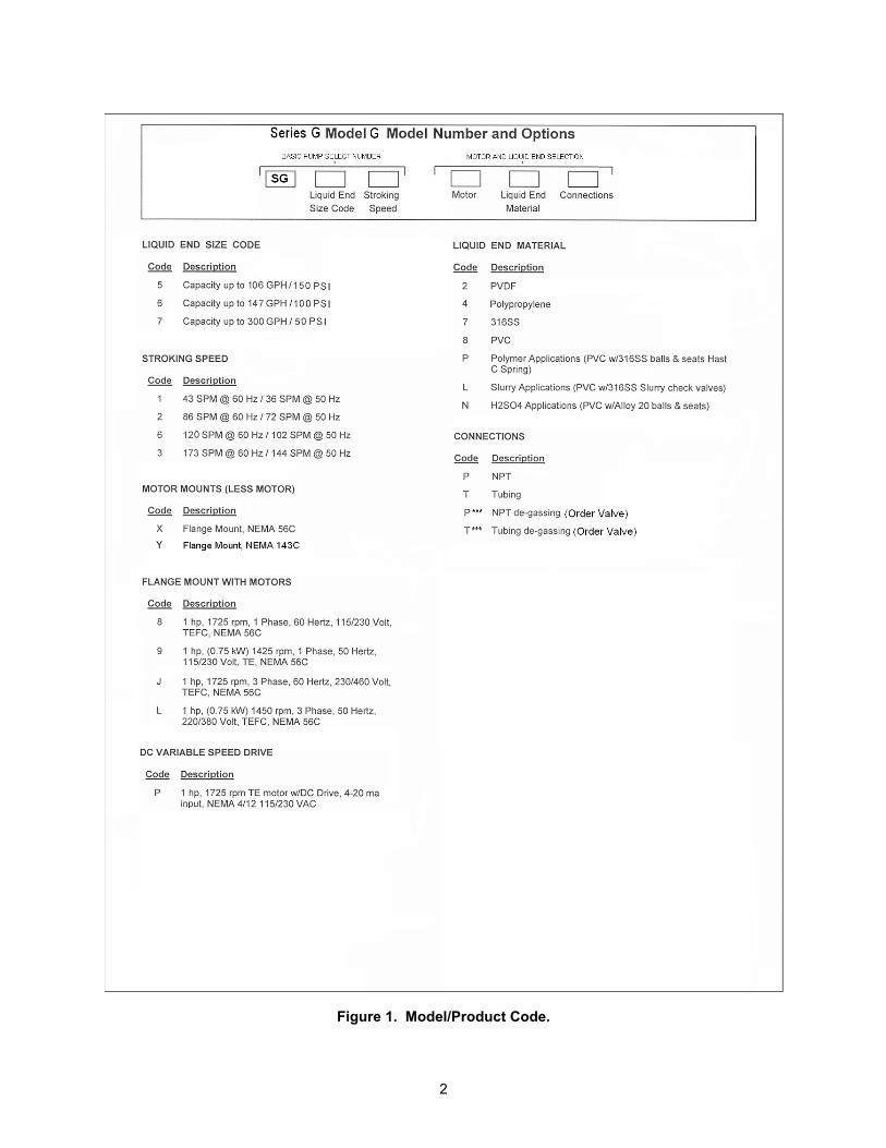
Figure 1. Model/Product Code.
3
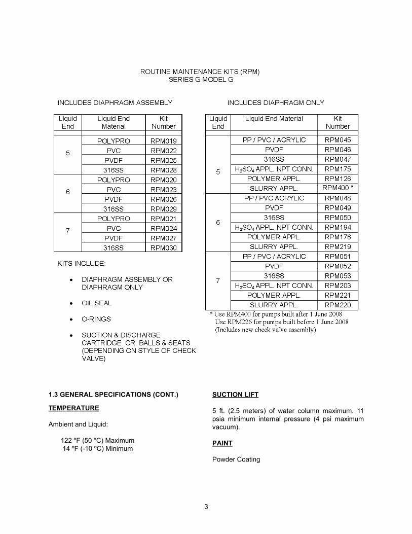
1.3 GENERAL SPECIFICATIONS (CONT.)
TEMPERATURE
Ambient and Liquid:
122 ºF (50 ºC) Maximum 14 ºF (-10 ºC) Minimum
SUCTION LIFT
5 ft. (2.5 meters) of water column maximum. 11psia minimum internal pressure (4 psi maximumvacuum).
PAINT
Powder Coating
4
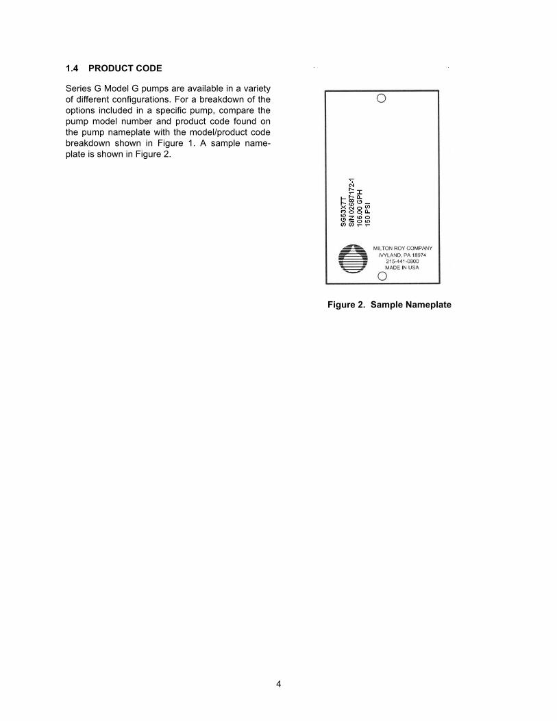
1.4 PRODUCT CODE
Series G Model G pumps are available in a varietyof different configurations. For a breakdown of theoptions included in a specific pump, compare thepump model number and product code found onthe pump nameplate with the model/product codebreakdown shown in Figure 1. A sample name-plate is shown in Figure 2.
Figure 2. Sample Nameplate
5
SECTION 2INSTALLATION
2.1 UNPACKING
Pumps are shipped f.o.b. factory or representativewarehouse and the title passes to the customerwhen the carrier signs for receipt of the pump. Inthe event that damages occur during shipment, it isthe responsibility of the customer to notify the car-rier immediately and to file a damage claim.
Carefully examine the shipping crate upon receiptfrom the carrier to be sure there is no obvious dam-age to the contents. Open the crate carefully soaccessory items fastened to the inside of the cratewill not be damaged or lost. Examine all materialinside the crate and check against packing list tobe sure that all items are accounted for and intact.
2.2 SAFETY PRECAUTIONS
WARNINGWHEN INSTALLING, OPERATING, ANDMAINTAINING THE SERIES G MODEL GPUMP, KEEP SAFETY CONSIDERA-TIONS FOREMOST. USE PROPERTOOLS, PROTECTIVE CLOTHING, ANDEYE PROTECTION WHEN WORKINGON THE EQUIPMENT AND INSTALLTHE EQUIPMENT WITH A VIEWTOWARD ENSURING SAFE OPERAT-ION. FOLLOW THE INSTRUCTIONS INTHIS MANUAL AND TAKE ADDITIONALSAFETY MEASURES APPROPRIATETO THE LIQUID BEING PUMPED. BEEXTREMELY CAREFUL IN THE PRES-ENCE OF HAZARDOUS SUBSTANCES(E.G., CORROSIVES, TOXINS, SOL-VENTS, ACIDS, CAUSTICS, FLAM-MABLES, ETC.).
THE PERSONNEL RESPONSIBLE FORINSTALLATION, OPERATION ANDMAINTENANCE OF THIS EQUIPMENTMUST BECOME FULLY ACQUAINTEDWITH THE CONTENTS OF THIS MAN-UAL.
ANY SERVICING OF THIS EQUIPMENTMUST BE CARRIED OUT WHEN THEUNIT IS STOPPED AND ALL PRES-SURE HAS BEEN BLED FROM THE LIQ-UID END. SHUT-OFF VALVES INSUCTION AND DISCHARGE SIDES OFTHE LIQUID END SHOULD BE CLOSEDWHILE THE UNIT IS BEING SERVICED.ACTIONS SHOULD BE TAKEN TO ELIM-INATE THE POSSIBILITY OF ACCIDEN-TAL START-UP WHILE SERVICING ISTAKING PLACE. A NOTICE SHOULD BEPOSTED BY THE POWER SWITCH TOWARN THAT SERVICING IS BEINGCARRIED OUT ON THE EQUIPMENT.SWITCH OFF THE POWER SUPPLY ASSOON AS ANY FAULT IS DETECTEDDURING OPERATION (EXAMPLES:ABNORMALLY HIGH DRIVE TEMPERA-TURE, UNUSUAL NOISE, DIAPHRAGMFAILURE).
2.3 STORAGE
Short Term Storage (Less than 6 Months)
It is preferable to store the material under a shelterin its original package to protect it from adverseweather conditions. In condensing atmospheres,follow the long term storage procedure.
Long Term Storage (Longer than 6 Months)
The primary consideration in storage of pumpequipment is to prevent corrosion of external andinternal components. This corrosion is caused bynatural circulation of air as temperature of the sur-roundings change from day to night, day to day,and from season to season. It is not practical toprevent this circulation which carries water vaporand other corrosive gasses, so it is necessary toprotect internal and external surfaces from theireffects to the extent possible.
When the instructions given in this section arecompleted, the equipment is to be stored shel-tered; protected from direct exposure to weather.
6
The prepared equipment should be covered with aplastic sheet or a tarpaulin, but in a manner whichwill allow air circulation and prevent capture ofmoisture. Equipment should be stored 12 inches ormore above the ground.
If equipment is to be shipped directly from MiltonRoy into long term storage, contact Milton Roy toarrange for factory preparation.
Pump Drive
1. Flood the gearbox compartment with a highgrade lubricating oil/rust preventative such asMobile Oil Corporation product “Mobilarma 524.”Fill the compartment completely to minimize airspace and water vapor condensation. After stor-age, drain this material and refill the equipmentwith the recommended lubricant for equipmentcommissioning.
2. Remove drive motor and liquid end, and brushall unpainted metal surfaces with multipurposegrease (NLGI grade 2 or 3). Store these unat-tached.
Electrical Equipment
1. Motors should be prepared in the manner pre-scribed by their manufacturer. If information is notavailable, dismount and store motors as indicatedin step 3 below.
2. Dismount electrical equipment (includingmotors) from the pump.
3. For all electrical equipment, place packets ofVapor Phase Corrosion Inhibitor (VPCI) inside ofthe enclosure, then place the entire enclosure, withadditional packets, inside a plastic bag. Seal thebag tightly closed. Contact your distributor or LMI/Milton Roy Service Department for recommendedVPCI materials.
2.4 MOUNTING
TO AVOID POSSIBLE DAMAGE TOEITHER PUMP OR PERSONNEL, BOLTPUMP DOWN AS SOON AS IT IS INPOSITION.
Support the pump firmly in a level position on asolid, vibration-free foundation, preferably with thebase above floor level to protect the pump fromwash downs and to provide easier access for ser-vice. Be sure to allow enough space around thepump for easy access during maintenance opera-tions, pump adjustments, and/or oil filling or drain-ing procedures.
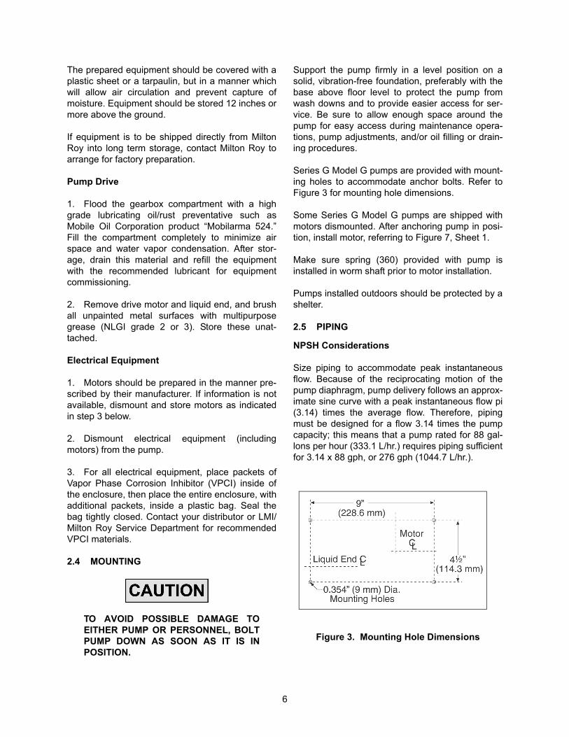
Series G Model G pumps are provided with mount-ing holes to accommodate anchor bolts. Refer toFigure 3 for mounting hole dimensions.
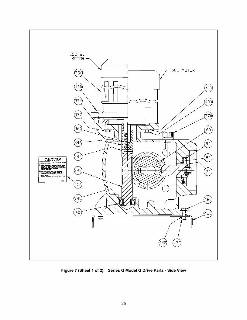
Some Series G Model G pumps are shipped withmotors dismounted. After anchoring pump in posi-tion, install motor, referring to Figure 7, Sheet 1.
Make sure spring (360) provided with pump isinstalled in worm shaft prior to motor installation.
Pumps installed outdoors should be protected by ashelter.
2.5 PIPING
NPSH Considerations
Size piping to accommodate peak instantaneousflow. Because of the reciprocating motion of thepump diaphragm, pump delivery follows an approx-imate sine curve with a peak instantaneous flow pi(3.14) times the average flow. Therefore, pipingmust be designed for a flow 3.14 times the pumpcapacity; this means that a pump rated for 88 gal-lons per hour (333.1 L/hr.) requires piping sufficientfor 3.14 x 88 gph, or 276 gph (1044.7 L/hr.).
Figure 3. Mounting Hole Dimensions
7
To minimize viscous flow losses when handling vis-cous liquids, it may be necessary to use suctionpiping up to four times larger than the size of thesuction connection on the pump. If in doubt, con-tact your nearest LMI Distributor to determine thenecessary pipe size.
General Piping Considerations
• Use extreme care in piping to plastic liquidend pumps with rigid pipe such as PVC. Ifexcessive stresses or vibration is unavoid-able, flexible connections are recom-mended.
• Use piping materials that will resist corro-sion by the liquid being pumped. Use carein selecting materials to avoid galvanic cor-rosion at pump liquid end connections.
• Use piping heavy enough to withstandmaximum pressures.
• Remove burrs, sharp edges, and debrisfrom inside piping. Blow out all pipe linesbefore making final connections to pump.
• Because vapor in the liquid end will causeinaccurate pump delivery, piping should besloped to prevent vapor pockets
• When pumping suspended solids (such asslurries), install plugged crosses at all 90°line turns to permit line cleaning withoutdismantling piping.
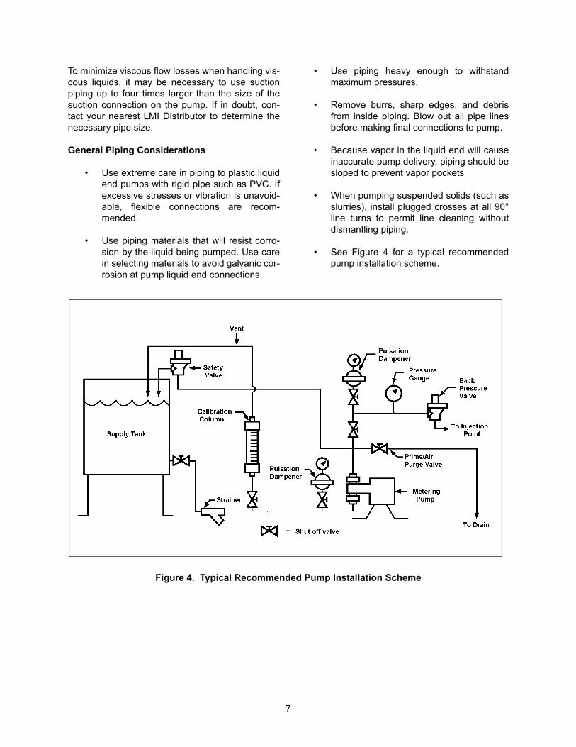
• See Figure 4 for a typical recommendedpump installation scheme.
Figure 4. Typical Recommended Pump Installation Scheme
8
Suction Piping Considerations
• It is preferable to have the suction of thepump flooded by locating the liquid endbelow the lowest level of the liquid in thesupply tank. Installing the supply vessel onthe suction line close to the pump can helpensure a flooded suction line. (Consult withyour LMI distributor or the LMI/Milton Roytechnical support team for assistance insuch applications.)
• Avoid negative suction pressure conditions(suction lift), as such conditions adverselyaffect metering accuracy. A lift of 8.2 feet(2.5 meters) of water column is the maxi-mum suction lift permissible.
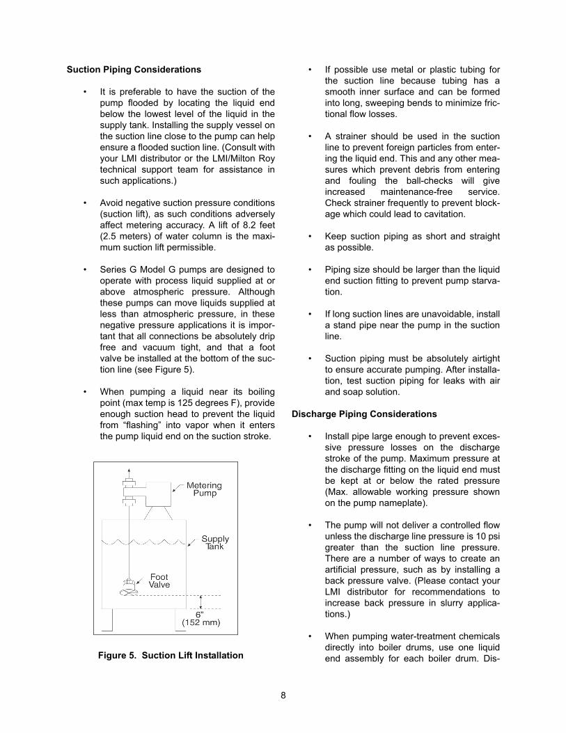
• Series G Model G pumps are designed tooperate with process liquid supplied at orabove atmospheric pressure. Althoughthese pumps can move liquids supplied atless than atmospheric pressure, in thesenegative pressure applications it is impor-tant that all connections be absolutely dripfree and vacuum tight, and that a footvalve be installed at the bottom of the suc-tion line (see Figure 5).
• When pumping a liquid near its boilingpoint (max temp is 125 degrees F), provideenough suction head to prevent the liquidfrom “flashing” into vapor when it entersthe pump liquid end on the suction stroke.
Figure 5. Suction Lift Installation
• If possible use metal or plastic tubing forthe suction line because tubing has asmooth inner surface and can be formedinto long, sweeping bends to minimize fric-tional flow losses.
• A strainer should be used in the suctionline to prevent foreign particles from enter-ing the liquid end. This and any other mea-sures which prevent debris from enteringand fouling the ball-checks will giveincreased maintenance-free service.Check strainer frequently to prevent block-age which could lead to cavitation.
• Keep suction piping as short and straightas possible.
• Piping size should be larger than the liquidend suction fitting to prevent pump starva-tion.
• If long suction lines are unavoidable, installa stand pipe near the pump in the suctionline.
• Suction piping must be absolutely airtightto ensure accurate pumping. After installa-tion, test suction piping for leaks with airand soap solution.
Discharge Piping Considerations
• Install pipe large enough to prevent exces-sive pressure losses on the dischargestroke of the pump. Maximum pressure atthe discharge fitting on the liquid end mustbe kept at or below the rated pressure(Max. allowable working pressure shownon the pump nameplate).
• The pump will not deliver a controlled flowunless the discharge line pressure is 10 psigreater than the suction line pressure.There are a number of ways to create anartificial pressure, such as by installing aback pressure valve. (Please contact yourLMI distributor for recommendations toincrease back pressure in slurry applica-tions.)
• When pumping water-treatment chemicalsdirectly into boiler drums, use one liquidend assembly for each boiler drum. Dis-
9
charging into a manifold having the slight-est pressure difference between its severaldischarge connections can diminish meter-ing accuracy as the outlet with the lowestpressure will receive more liquid than theother outlets.
Back Pressure Valves
A Milton Roy Back Pressure Valve (Figure 4)should be installed in the discharge line near thepump to ensure sufficient discharge head pressurefor proper pump metering action. Back pressurevalves for large pumps with long and extremelysmall discharge lines may have to be installed nearthe point of discharge into the process (to minimizesiphoning tendencies).
Pulsation Dampeners
An accumulator, surge chamber, surge suppressor,or pulsation dampener should be used with theback pressure valve in the discharge line to absorbthe flow peaks between the pump and the backpressure valve. Without the pulsation dampenerthe valve mechanism will snap open and closedwith the surge from each pump stroke. The pulsa-tion dampener will allow the back pressure valve tooscillate about a partly-closed position, thus mini-mizing wear on the valve. Discharge line pulsationdampeners offer the further advantage of limitingthe flow and pressure variations characteristic ofthis kind of pump. Installing a properly sized pulsa-tion dampener will improve pump performance andmay reduce system costs dramatically by permit-ting the substitution of smaller piping. Please con-tact your LMI distributor for further information onpulsation dampeners.
Safety Valves
Motor-driven positive displacement pumps candevelop excessive discharge pressures longbefore thermal overload devices interrupt the motorelectrical circuit. To prevent a blocked dischargeline from causing damage to the pump, piping, orprocess equipment, install a Milton Roy SafetyValve in the pump discharge line. This valve isdesigned and sized to handle system flow ratesand pressures safely while resisting corrosion bythe process liquid.
Install the safety valve in the discharge linebetween the pump and the nearest shut-off valve.(This will prevent pump damage from accidentalvalve closure.) Pipe the safety valve outlet back tothe suction tank or to drain, but in either caseensure that the pipe end is continuously visible sosafety valve leakage may be detected. Milton Roysafety valves must be installed at top of supply tankin order to function properly (see Figure 4).
Check Valves
A check valve should be installed at the pointwhere the discharge line enters a boiler or otherhigh-pressure vessel. This will prevent back flowthrough the discharge piping and will isolate thepump discharge from system pressures (a safetyconsideration).
Shut-off Valves
Provide shut-off valves in both suction and dis-charge lines next to the pump. Locate dischargeline shut-off valve downstream from the inlet con-nection of the safety valve. Figure 4 shows recom-mended valve locations.
2.6 LEAK DETECTION
The Series G Model G pumps are equipped with aleak detection port. For ease of installation, eachpump has a plastic tubing connector installed in theleak detection port (see item 448 in Figure 7, Sheet2). In the event of a failure of the oil seal (70 in Fig-ure 7, Sheet 1) or PTFE diaphragm assembly (260in Figures 8 through 13), pump drive oil or processfluid will escape from this leakage port. Duringpump installation, actions should be taken to insurethat this leakage is safely collected by installingtubing between the leak detection port and anappropriate containment vessel.
2.7 ELECTRICAL CONNECTIONS
Ensure that the electrical supply matches the pumpmotor nameplate characteristics.
OPERATION WITH THE WRONGMOTOR ROTATION WILL DAMAGE THEPUMP AND MOTOR AND VOID THEWARRANTY.
10
Before operating the pump, check the direction ofrotation of the motor to be sure it matches thedirection of the arrow stamped on the motor (rota-tion should be clockwise when viewed from the topof the motor). If motor rotation is incorrect, refer tothe motor data plate or motor manufacturer’sinstructions for reversing.
DO NOT FORGET TO CONNECT THEPUMP TO AN EARTH GROUND!
Electric protection of the motor (fuses, overloadmeters or relays) should correspond to the ratedcurrent indicated on the motor data plate.
11
SECTION 3OPERATION
3.1 INITIAL START-UP
WARNINGFAILURE TO CHECK TORQUE ON NON-METALLIC HEAD BOLTS PRIOR TOSTARTUP AND AFTER ONE WEEK OFOPERATION MAY EXPOSEOPERATING PERSONNEL TOHAZARDOUS LIQUIDS.
Check the torque on all non-metallic head boltsprior to startup. Recheck torque on all non-metallichead bolts after pump has been operating for oneweek. Torque the head assembly screws in acrosswise pattern as follows:
(1) Liquid End Size SG5 and SG6 non-metallichead bolts to 90 inch pounds.
(2) Liquid End Size SG7 non-metallic headbolts to 125 inch pounds.
Check that all mounting bolts are tight, piping isinstalled properly, and the discharge line is open.
Check oil drain plug for tightness. Remove the oilfill cap and fill the pump casing until level isbetween the markings on the oil fill cap dipstick,(approximately 3 quarts (2.8 Liters)).
NOTE: The oil furnished with the pump isgrade AGMA No. 5 EP with a viscosity of 1000SSU at 100°F (218.4 cSt at 40°C). For opera-tion in ambient temperatures below 50°F(10°C), substitute AGMA No. 2 EP with a vis-cosity of 400 SSU at 100°F (86.4 cSt at 40°C).Manufacturers' equivalent oils are shownbelow.NOTE:
ABOVE 50°FChevron ................. N.L. Gear Compound 220Exxon .................... Spartan E.P. 220Mobil ...................... Mobilgear 630Texaco ................... Meropa 220Shell ...................... Omaha 220
BELOW 50°FChevron ................. N.L. Gear Compound 68
Exxon .....................Spartan E.P. 68Mobil ......................Mobilgear 626Texaco ...................Meropa 68Shell .......................Omaha 68
BEFORE SWITCHING ON POWER TOTHE PUMP, TURN THE CAPACITYADJUSTMENT KNOB TO ZERO. CHECKTHAT ALL SHUT-OFF VALVES IN THESUCTION AND DISCHARGE LINES AREOPEN BEFORE INCREASING THECAPACITY ADJUSTMENT FROM ZERO.
DO NOT TRY TO ADJUST PUMPCAPACITY BELOW O% OR ABOVE100% OR DAMAGE TO PUMP MAYOCCUR. KEEP ADJUSTMENT KNOBBETWEEN 0 AND 100 %.
Manual Capacity Control
To adjust pump capacity, loosen the stroke lockingknob (320, Figure 7, Sheet 2) located in the pump-side cover. Pump capacity is adjusted by turningthe micrometer type stroke adjustment knob (330)clockwise to decrease capacity or counterclock-wise to increase capacity as required. The adjust-ment scale is marked in percent (%) of full stroke,with calibration lines on the knob at 1% intervals.After adjusting the knob to the desired capacity set-ting, hand tighten the stroke locking screw to main-tain the capacity setting.
Filling Pumping System
It is especially important that pump suction and dis-charge lines be free of entrained air. To ensure thiscondition, operate the pump without any dischargepressure and fill the entire pumping system with liq-uid before starting pressure tests. A simple methodto assure priming of the pump is to install a tee anda shut-off valve at the discharge connection of thepump.
12
If the pump is idle for long periods, temperaturechanges in the process liquid may produce air inthe system. To discharge the air, install a valve inthe discharge line which will allow the process liq-uid to be pumped to exhaust when starting thepump.
Capacity Calibration
After the first 12 hours of operation, the pump maybe tested and calibrated to find the exact pumpcapacity under specific operating conditions.
Usually, calibrating the pump at only 100, 50, and10 percent capacity settings is enough to indicatepump performance throughout the adjustmentrange.
The pump can be calibrated by measuring thedecrease in liquid level pumped from a calibratedvessel. This method is recommended for hazard-ous liquids because it eliminates operator contactwith the liquid. Milton Roy test-tube Calibration Col-
umns are available for convenient and accuratecalibration of any pump.
THE FOLLOWING METHOD IS NOTGENERALLY RECOMMENDED AS ITMAY EXPOSE OPERATING PERSON-NEL TO HAZARDOUS LIQUIDS. FUTH-ERMORE, THE PUMP MAY OVER PUMPDRAMATICALLY AND THE POSITIONOF THE CAPACITY ADJUSTMENTKNOB MAY HAVE LITTLE EFEECT ONMEASURING FLOW RATE.
The pump can also be calibrated by collecting andmeasuring pumped liquid at the pump dischargeport. It may be necessary to create discharge headat the liquid takeoff point so that the pump willoperate properly. (See Section 2 for recommendedways to do this.)
13
SECTION 4MAINTENANCE
4.1 SPARE PARTS
To avoid excessive downtime in the event of aparts malfunction, the spare parts shown belowshould be stocked for each pump to prevent seri-ous delays in repairs. Refer to Figures 8–14 andthe accompanying parts lists. For your conve-nience, these parts can be purchased either sepa-rately or packaged in the form of RoutinePreventive Maintenance (RPM) Kits. RPM kitnumbers are listed in Section 1.
RPM kit numbers RPM019 through RPM030 con-tain pre-assembled diaphragms, oil seal and checkvalve parts. Cap piece (240), set screw (250), dia-phragm (260), and support nut (270) is pre-assem-bled in kits RPM019 through RPM030. A spannerwrench, which may not always be available in thefield, is required to disassemble the diaphragmassembly.
RPM Kits RPM045 through RPM053 and RPM126,through RPM220 contain a diaphragm, oil seal,and check valve parts. Series G Model G pumpsbuilt with the latest design do not need a spannerwrench to disassemble the diaphragm assembly.The diaphragm assembly can be disassembledwith a 30mm socket (Section 4, paragraph 4.4.2).The diaphragm can then be replaced.
Either type of kit can be used for your pump. Theuser must decide which type is better for them.When ordering RPM Kits RPM045 throughRPM053 for an old style pump, where a spannerwrench is required to disassemble the diaphragmassembly, order a new hex head support nut (270)with the RPM kit. Future maintenance on the Mac-roy pump will not require a spanner wrench.
SG5, Metallic Liquid End
(1) Diaphragm (260)
(2) Oil Seal (70)
(3) Check Valve Assemblies (425)
(See parts list)
All Other Liquid Ends
(1) Diaphragm (260)
(2) Oil Seal (70)
(3) Seat, O-Ring, Ball Set (423)
(See parts list)
Parts orders must include the following:
1. Quantity required
2. Part number
3. Part description
4. Pump serial number (found on nameplate)
5. Pump model number (found on nameplate)
6. Pump product code (found on nameplate)
Always include the serial number, model number,and product code in all correspondence regardingthe unit.
Drive Worms and Gears
Worms (Fig 7, Item 342) and gears (50) must besold in sets to assure proper operation.
4.2 SHIPPING PUMPS FOR REPAIR
Pumps can not be accepted for repair without aReturn Material Authorization. Pumps should beclearly labeled to indicate the liquid being pumped.Process liquid should be flushed from the pump liq-uid end and oil should be drained from the pumphousing before the pump is shipped.
NOTE: Federal law prohibits handling ofequipment that is not accompanied by anOSHA Material Safety Data Sheet (MSDS). Acompleted MSDS must be packed in the ship-ping crate with any pump shipped for repair.These safety precautions will aid the trouble-shooting and repair procedure and precludeserious injury to repair personnel from hazard-
14
ous residue in pump liquid end. A MaterialsSafety Data Sheet must accompany all returns.
All inquiries or parts orders should be addressed toyour local LMI representative or distributor.
4.3 PREVENTIVE MAINTENANCE
LMI pumps are carefully designed, manufactured,assembled, and quality tested to give reliable ser-vice with minimal maintenance. However, a weeklymaintenance check is recommended to visuallyconfirm proper operation of the pump.
Drive
Initially, change gear drive oil after the first 250hours of operation. Then change drive oil afterevery 4000 hours of operation or every six months,whichever comes first. Refer to “Initial Start-up” inSection 3, Operation, for information on recom-mended oil and oil capacity.
NOTE: When adding oil, pour in a thin, slowstream to avoid overflow.
Diaphragm Assembly
The Series G Model G diaphragm assembly shouldbe replaced every 4000 hours of operation to avoidthe possibility of failure. Refer to the instructions inthe “Corrective Maintenance” section.
Oil Seal
The Series G Model G oil seal should be replacedevery 4000 hours of operation to avoid the possibil-ity of failure. Oil seal replacement requires theremoval of the diaphragm assembly, so it is recom-mended that the oil seal and diaphragm bereplaced at the same time. Refer to the instructionsin the “Corrective Maintenance” section.
Check Valves
LMI recommends that check valve balls, seats,gaskets, and o-rings be replaced on a annualbasis. If highly corrosive material (acids, slurries,etc.) is being pumped, some applications mayrequire more frequent replacement.
To determine if check valves need maintenance,disassemble the check valves following the instruc-tions in the “Corrective Maintenance” section.
Inspect the ball check and seat for chemical orphysical damage. The ball should be perfectlyround and free of pits, mars, or scratches. The seatshould retain a sharp edge where the ball contactsfor proper sealing. If the seat edge is worn or dam-aged, or has any pits, mars, or scratches, it shouldbe replaced. If the ball and/or seat is excessivelydamaged, the replacement schedule should beshortened accordingly. If the ball and seat are bothin good condition, the replacement schedule canbe lengthened.
Complete instructions for replacing worn checkvalve parts are given in the “Corrective Mainte-nance” section.
4.4 CORRECTIVE MAINTENANCE
BEFORE CARRYING OUT ANY SERVIC-ING OPERATION ON THE METERINGUNIT OR PIPES, DISCONNECT ELEC-TRICAL POWER FROM THE PUMP,AND TAKE THE NECESSARY STEPSTO ENSURE THAT THE HARMFUL LIQ-UID THEY CONTAIN CANNOT ESCAPEOR COME INTO CONTACT WITH PER-SONNEL. SUITABLE PROTECTIVEEQUIPMENT MUST BE PROVIDED.CHECK THAT ALL PRESSURE HASBEEN BLED FROM THE PUMP DRIVEAND PUMP LIQUID END BEFORE PRO-CEEDING WITH DISMANTLING.
Cleaning Fouled Check Valves
Check valve assemblies are designed to be selfcleaning and should seldom need servicing.Fouled check valves can usually be cleaned bypumping a solution of mild detergent and warmwater (if compatible with liquid being pumped) for15 minutes, followed by flushing with water.
4.4.1 Check Valve Replacement
General
Before beginning work on the valve assemblies,make sure the shut-off valves are closed and thatpressure has been bled from the system. Whenreplacing the valves, take care to systematicallychange their O-rings and/or gaskets. Take care to
15
properly assemble the valve assemblies; the ballmust be placed on the sharp edge of the seats.
Check valves are supplied in four different configu-rations: plastic, stainless steel, slurry, and polymer.Be sure to refer to the appropriate instructional setbelow.
BE SURE TO FOLLOW INSTRUCTIONSCAREFULLY AND REFER TO THEAPPROPRIATE FIGURE WHEN REAS-SEMBLING CHECK VALVES. IF CHECKVALVE CARTRIDGES ARE INSTALLEDINCORRECTLY, ONE OF THE FOLLOW-ING WILL OCCUR: (A) IMMEDIATESEVERE DAMAGE TO PUMP MECHA-NISM, (B) NO PUMPING, (C) REVERSEPUMPING ACTION (FROM DISCHARGELINE INTO SUCTION LINE).
4.4.1.1 Plastic Check Valves (PVC, PVDF, Polypropylene, and Sulfuric Acid Service, Fig. 14A or 14C):
Disassembly
Check pump data plate for model number.
1. Unscrew the union nut (435). The union end(445) is held in place by the union nut and will sep-arate easily from the other liquid end parts.
2. Unscrew the ball guide (424) from the liquidend.
3. Screw the union nut part way (one or twoturns) onto the end of the ball guide that has theseat in it. Be sure the union nut is on loosely. Thiswill allow a gap for the seat (420) to fall into as it isremoved from the ball guide.
4. Set the ball guide/union nut onto a flat surfacewith the union nut down. Looking into the top ofthe ball guide, you will see four large holes sur-rounding one small hole. Insert a thin, blunt instru-ment such as a hex head screwdriver into the smallcenter hole until it rests on the top of the ball (422).
IF YOU ARE DISASSEMBLING UNITFOR INSPECTION ONLY, BE SURE TOUSE A BLUNT INSTRUMENT AND TAPGENTLY TO AVOID DAMAGING THEBALL. IF THE BALL AND/OR SEAT AREDAMAGED DURING DISASSEMBLY,THEY WILL HAVE TO BE REPLACED. IFAVAILABLE, TO AVOID DAMAGE, IT ISADVISABLE TO USE GENTLE AIRPRESSURE (APPLIED AT END OPPO-SITE THE SEAT - 420) FOR BALL ANDSEAT REMOVAL.
5. Tap screwdriver gently with a hammer until theball and seat are released from the ball guide.
6. Carefully remove the two or three o-rings (de-pending on model number) from the ball guide andseat.
7. Carefully clean any parts to be reused. If anychemicals are used in the cleaning process,ensure that they are compatible with the processliquid.
Reassembly
1. Fit new o-rings into position on the ball guideand seat.
NOTE: To assure a tight, leak free seal, newo-rings should be used each time the checkvalves are disassembled.
2. Drop the ball into the curved inner chamberend of the ball guide.
IF THE SEAT IS IMPROPERLY POSI-TIONED, THE BALL WILL NOT CREATEA TIGHT SEAL AND POOR PUMPINGPERFORMANCE WILL RESULT.
3. Set the ball guide on a flat surface so that theside with the ball faces upwards. Position seat onthe ball guide, trapping the ball inside. When theseat is pressed into the ball guide, the bevelededge of the seat must be facing outward. The
16
bevel should not face the inside of the check valve(refer to Figure 14A or 14C). Use a flat surfacesuch as a board to press the seat into the ballguide with firm, even pressure.
THE ORDER OF ASSEMBLY AND ORI-ENTATION OF THE SUCTION AND DIS-CHARGE CHECK VALVES ISDIFFERENT. REFER TO FIGURE 8, 10,12, 14A, AND 14C FOR PROPERASSEMBLY ORDER AND ORIENTA-TION. IF CHECK VALVE CARTRIDGESARE INSTALLED INCORRECTLY, ONEOF THE FOLLOWING WILL OCCUR: (A)IMMEDIATE SEVERE DAMAGE TOPUMP MECHANISM, (B) NO PUMPING,(C) REVERSE PUMPING ACTION(FROM DISCHARGE LINE INTO SUC-TION LINE).
4. Position the union end (445) onto the correctend of the ball guide. Refer to Figure 14A or 14C,as the correct end is determined by whether thevalve is intended for the suction or discharge portof the liquid end. Slip the union nut (435) over theunion end and screw tightly (hand tight only) ontothe ball guide.
5. Screw the valve assembly into the liquid endbody (hand tight only). DO NOT OVERTIGHTEN.
4.4.1.2 Models SG6 & SG7 Liquid Ends - Stain-less Steel Check Valves (Figure 14D):
Disassembly
1. Unscrew the three screws (441 & 442) andremove them and their three washers (439).
2. Remove the valve clamp (437).
3. The connection (435), seat (420), ball (422)and ball guide (424) should all now slip apart eas-ily.
4. Remove and discard the three gaskets (419).
5. Carefully clean any parts to be reused. If anychemicals are used in the cleaning process,
ensure that they are compatible with the processliquid.
Reassembly
1. Drop the ball into the curved inner chamberend of the ball guide.
DO NOT REUSE OLD GASKETS (419).EVEN IF BALL AND SEAT ARE NOTWORN AND DO NOT NEED REPLAC-ING, NEW GASKETS MUST BE USEDANY TIME THE CHECK VALVES AREDISASSEMBLED.
2. Place a new gasket on the rim of the ball guide(424), and sit the seat on top of the ball guide, trap-ping the ball and gasket between the seat and ballguide.
THE ORDER OF ASSEMBLY AND ORI-ENTATION OF THE SUCTION AND DIS-CHARGE CHECK VALVES ISDIFFERENT. REFER TO FIGURE 11, 13,AND 14D FOR PROPER ASSEMBLYORDER AND ORIENTATION. IF CHECKVALVE CARTRIDGES ARE INSTALLEDINCORRECTLY, ONE OF THE FOLLOW-ING WILL OCCUR: (A) IMMEDIATESEVERE DAMAGE TO PUMP MECHA-NISM, (B) NO PUMPING, (C) REVERSEPUMPING ACTION (FROM DISCHARGELINE INTO SUCTION LINE).
3. Position the connection (435) onto the correctend of the ball guide with a gasket trappedbetween the two metal surfaces. Refer to Figure14D, as the correct end is determined by whetherthe valve is intended for the suction or dischargeport of the liquid end.
4. Position the check valve assembly onto the liq-uid end, trapping a gasket between the two metalsurfaces (seat and pump head).
5. Slide the valve clamp (437) over the connec-tion (435) and screw into the liquid end using the
17
three screws (441,442) and their split washers(439). Since one screw (441) is shorter than theothers, be sure that it is screwed into the appropri-ate hole.
4.4.1.3 Model SG5 Liquid End - Stainless SteelCheck Valve (Fig. 14B):
Disassembly
SG5 stainless steel check valves differ from theplastic versions in that the ball seat is integral tothe ball guide. The seats cannot easily beinspected for damage or wear. If you suspect thatthe check valve may be damaged or worn, replacethe entire check valve assembly as per the instruc-tions below.
1. Unscrew the coupling (445).
2. Unscrew the ball guide (424) from the liquidend.
3. Remove and discard the o-rings (419).
4. Carefully clean any parts to be reused. If anychemicals are used in the cleaning process,ensure that they are compatible with the processliquid.
Reassembly
THE ORDER OF ASSEMBLY AND ORI-ENTATION OF THE SUCTION AND DIS-CHARGE CHECK VALVES ISDIFFERENT. REFER TO FIGURE 9 AND14B FOR PROPER ASSEMBLY ORDERAND ORIENTATION. IF CHECK VALVECARTRIDGES ARE INSTALLED INCOR-RECTLY, ONE OF THE FOLLOWINGWILL OCCUR: (A) IMMEDIATE SEVEREDAMAGE TO PUMP MECHANISM, (B)NO PUMPING, (C) REVERSE PUMPINGACTION (FROM DISCHARGE LINE INTOSUCTION LINE).
1. Screw the correct end of the check valveassembly into the liquid end (refer to Figure 14B),trapping a new o-ring between the liquid end andthe check valve assembly.
NOTE: To assure a tight, leak free seal, newo-rings should be used each time the checkvalves are disassembled.
2. Screw the coupling (445) onto the check valveassembly, trapping a new o-ring (419, 423)between the coupling and the check valve assem-bly.
4.4.1.4 Model SG5 Liquid End - Slurry Service Check Valves, use until 1 June 2008 (Fig. 14E) :
Replacement
THE ORDER OF ASSEMBLY AND ORI-ENTATION OF THE SUCTION AND DIS-CHARGE CHECK VALVES ISDIFFERENT. REFER TO FIGURE 8 AND14E FOR PROPER ASSEMBLY ORDERAND ORIENTATION. IF CHECK VALVECARTRIDGES ARE INSTALLED INCOR-RECTLY, ONE OF THE FOLLOWINGWILL OCCUR: (A) IMMEDIATE SEVEREDAMAGE TO PUMP MECHANISM, (B)NO PUMPING, (C) REVERSE PUMPINGACTION (FROM DISCHARGE LINE INTOSUCTION LINE).
1. Unscrew the coupling (445).
2. Unscrew the valve body (424) from the pumphead (280).
3. Remove and discard the valve assembly:assembly includes two O-rings (419), slurry sealring (420), ball (422), check valve body (424), anddowel pin.
4. Clean the new valve assembly and threadedport in the head (280).
NOTE: To assure a tight, leak free seal, newo-rings should be used each time the checkvalves are disassembled.
5. Screw correct end of check valve assembly intoliquid end (refer to Figure 14E), trapping a new o-ring (419) between liquid end and check valveassembly.
18
6. Screw coupling (445) onto check valve assem-bly, trapping a new o-ring (419) between couplingand check valve assembly.
4.4.1.5 Models SG5, SG6 & SG7 Liquid End - Slurry Service Check Valves (Figure 14E & 14G):
Replacement
THE ORDER OF ASSEMBLY AND ORI-ENTATION OF THE SUCTION AND DIS-CHARGE CHECK VALVES ISDIFFERENT. REFER TO FIGURE 14GFOR PROPER ASSEMBLY ORDER ANDORIENTATION. IF CHECK VALVE CAR-TRIDGES ARE INSTALLED INCOR-RECTLY, ONE OF THE FOLLOWINGWILL OCCUR: (A) IMMEDIATE SEVEREDAMAGE TO PUMP MECHANISM, (B)NO PUMPING, (C) REVERSE PUMPINGACTION (FROM DISCHARGE LINE INTOSUCTION LINE).
1. Unscrew valve body (424) from pump head(280).
2. Remove the valve assembly (425): assemblyincludes ball (421 or 422), seat (420), retain pin(428, SG5 only), valve body (424), and two (SG5)or three (SG6 & SG7 O-rings (419).
3. Remove and discard o-rings (419), seat (420)and ball (421 or 422).
4. Clean valve body (424) and threaded port inhead (280).
5. Place a new O-ring (419) around seat (420).Place new seat (420) and new ball (421 or 422)inside valve body (424).
6. Add O-ring (419) and install new check valveassembly in orientation shown.
NOTE: To assure a tight, leak free seal, newo-rings should be used each time the checkvalves are disassembled.
7. Screw correct end of check valve assembly intoliquid end (refer to Figure 14E or 14G), trapping a
new o-ring (419) between liquid end and checkvalve assembly.
8. Screw coupling (445) onto check valve assem-bly, trapping a new o-ring (419) between couplingand check valve assembly.
4.4.1.6 Models SG5, SG6 & SG7 Liquid End - Polymer Service Check Valves (Figure 14F): Replacement
Suction
Follow the instruction for replacement of ball, seat,& seal: liquid end SG6 and SG7 - plastic checkvalves paragraph 4.4.1.1. The procedures are thesame.
Discharge
1. Unscrew valve body (425) from pump head(280).
2. Remove valve assembly: assembly includestwo O-rings (419), seat (420), ball (422), poppet(426), spring (423) and check valve body (425).
3. Replace O-rings (419), seat (420), ball (422),poppet (426), and spring (423).
4. Clean valve body (425) and threaded port inhead (280).
5. Install new check valve assembly in orientationshown.
On discharge side, drop cartridge assembly intothreaded port in head. Screw valve body into dis-charge side of diaphragm head until valve is handtight. DO NOT OVERTIGHTEN.
4.4.2 Diaphragm Replacement
BEFORE BEGINNING DIAPHRAGMREPLACEMENT, MAKE SURE THATALL SHUT-OFF VALVES ARE CLOSEDAND ALL PRESSURE IS BLED FROMTHE LIQUID END. MAKE SURE POWERTO PUMP IS TURNED OFF AND CAN-NOT BE ACTIVATED.
19
It is recommended that the oil seal and diaphragmbe replaced at the same time. The instructionsgiven under “Replacing the Oil Seal” are completeinstructions for replacing both the oil seal and dia-phragm. If you plan to replace both, refer to the“Replacing the Oil Seal” instructions, and disregardthe instructions below. These instructions areintended for use only if the diaphragm is beingreplaced independent of the oil seal.
4.4.2.1 Diaphragm Removal (All types; Refer to Figures 6-13)
1. Set the stroke adjusting knob to 100%.
2. Disconnect the suction and discharge piping.
3. Unscrew the six diaphragm head bolts (290).
4. Remove the pump head (280) from the pumpbody.
5. Turn the motor fan by hand (remove the motorshroud if necessary) until the end of the diaphragm(240) is fully forward, and unscrew the diaphragmassembly from the connecting rod (60).
Figure 6. Diaphragm Assembly
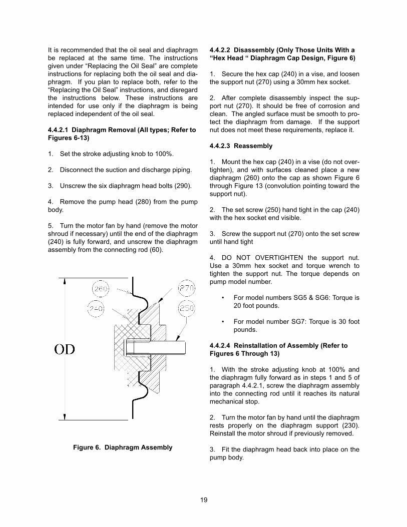
4.4.2.2 Disassembly (Only Those Units With a “Hex Head “ Diaphragm Cap Design, Figure 6)
1. Secure the hex cap (240) in a vise, and loosenthe support nut (270) using a 30mm hex socket.
2. After complete disassembly inspect the sup-port nut (270). It should be free of corrosion andclean. The angled surface must be smooth to pro-tect the diaphragm from damage. If the supportnut does not meet these requirements, replace it.
4.4.2.3 Reassembly
1. Mount the hex cap (240) in a vise (do not over-tighten), and with surfaces cleaned place a newdiaphragm (260) onto the cap as shown Figure 6through Figure 13 (convolution pointing toward thesupport nut).
2. The set screw (250) hand tight in the cap (240)with the hex socket end visible.
3. Screw the support nut (270) onto the set screwuntil hand tight
4. DO NOT OVERTIGHTEN the support nut.Use a 30mm hex socket and torque wrench totighten the support nut. The torque depends onpump model number.
• For model numbers SG5 & SG6: Torque is20 foot pounds.
• For model number SG7: Torque is 30 footpounds.
4.4.2.4 Reinstallation of Assembly (Refer to Figures 6 Through 13)
1. With the stroke adjusting knob at 100% andthe diaphragm fully forward as in steps 1 and 5 ofparagraph 4.4.2.1, screw the diaphragm assemblyinto the connecting rod until it reaches its naturalmechanical stop.
2. Turn the motor fan by hand until the diaphragmrests properly on the diaphragm support (230).Reinstall the motor shroud if previously removed.
3. Fit the diaphragm head back into place on thepump body.
20
4. Torque the six diaphragm head bolts to the fol-lowing inch pounds in a crisscross pattern:
(1) Liquid End Size SG5 and SG6 metallic andnon-metallic head bolts to 90 inch pounds.
(2) Liquid End Size SG7 non-metallic headbolts to 125 inch pounds.
(3) Liquid End Size SG7 metallic head bolts to250 inch pounds.
4.4.3 Replacing Oil Seal
BEFORE BEGINNING OIL SEALREPLACEMENT, MAKE SURE THATALL SHUT-OFF VALVES ARE CLOSEDAND ALL PRESSURE IS BLED FROMTHE LIQUID END. MAKE SURE POWERTO PUMP IS TURNED OFF AND CAN-NOT BE ACTIVATED.
When replacing the oil seal, the diaphragm assem-bly must be removed first. For ease of service, it isrecommended that the oil seal be replaced in con-junction with the diaphragm assembly. Therefore,the instructions below include the “DiaphragmReplacement” instructions, and can be used forboth oil seal replacement and diaphragm replace-ment.
Disassembly (Refer to Figure 6 through 13).
1. Drain oil from the pump by unscrewing drainplug and O-ring, located underneath capacityadjustment knob (330).
2. Set the capacity adjusting knob (330) to 100%.
3. Disconnect the suction and discharge piping.
4. Unscrew the six diaphragm head bolts.
5. Remove the diaphragm head assembly fromthe pump body.
6. Turn the motor fan by hand (remove theshroud if necessary) until the end of the diaphragmassembly (240) is fully forward, and unscrew the
diaphragm from the connecting rod (60), using a30mm hex socket on diaphragm cap (240).
7. Remove the diaphragm support ring (230).
8. Remove the retaining ring (220) from the con-necting rod.
9. Slide the small oil seal clamp (210) off theconnecting rod.
10. Remove the large oil seal clamp (80) byunscrewing the four slotted screws (90).
11. Pull the oil seal (70) off of the connecting rod.
Reassembly (Refer to Figure 6 through 13).
1. Install a new oil seal (70) onto the connectingrod.
2. Slide small oil seal clamp (210) onto the end ofthe connecting rod and secure in place with theretaining ring (220). A drive socket large enough tofit over the end of the connecting rod should beused to push the retaining ring until it snaps intoplace in the retaining ring groove in the connectingrod.
3. Secure the large oil seal clamp (80) over the oilseal with the four slotted screws (90).
4. Place the diaphragm support ring (230) intoposition making sure beveled side (for diaphragmsupport) is facing up (refer to Figure 6 through 13).For SG7 liquid ends, the support ring (230) hasstepped diameters. Make sure that the largerdiameter is installed into the metal adapter ring(225 Figure 12 and 13).
5. With the stroke adjusting knob at 100% andthe diaphragm fully forward as in steps 2 and 6 ofdisassembly instructions, screw the diaphragmassembly into the connecting rod until it reaches itsnatural mechanical stop.
6. Turn the motor fan by hand until the diaphragmrests properly on the diaphragm support ring (230).Reinstall the motor shroud if previously removed.With the stroke adjusting knob at 100% and thediaphragm fully forward as in steps 2 and 6 of dis-assembly instructions, screw the diaphragmassembly into the connecting rod until it reaches itsnatural mechanical stop.
21
7. Fit the diaphragm head back into place on thepump body.
8. Torque the six diaphragm head bolts to the fol-lowing inch pounds in a crisscross pattern:
(1) Liquid End Size SG5 and SG6 metallic andnon-metallic head bolts to 90 inch pounds.
(2) Liquid End Size SG7 non-metallic headbolts to 125 inch pounds.
(3) Liquid End Size SG7 metallic head bolts to250 inch pounds.
4. Add oil to pump, following directions given in“Initial Start-up” in Section 3.
22
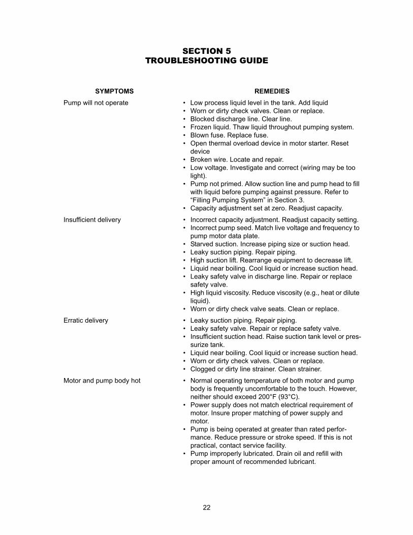
SECTION 5TROUBLESHOOTING GUIDE
SYMPTOMS REMEDIES
Pump will not operate • Low process liquid level in the tank. Add liquid• Worn or dirty check valves. Clean or replace.• Blocked discharge line. Clear line.• Frozen liquid. Thaw liquid throughout pumping system.• Blown fuse. Replace fuse.• Open thermal overload device in motor starter. Reset
device• Broken wire. Locate and repair.• Low voltage. Investigate and correct (wiring may be too
light).• Pump not primed. Allow suction line and pump head to fill
with liquid before pumping against pressure. Refer to “Filling Pumping System” in Section 3.
• Capacity adjustment set at zero. Readjust capacity.
Insufficient delivery • Incorrect capacity adjustment. Readjust capacity setting.• Incorrect pump seed. Match live voltage and frequency to
pump motor data plate.• Starved suction. Increase piping size or suction head.• Leaky suction piping. Repair piping.• High suction lift. Rearrange equipment to decrease lift.• Liquid near boiling. Cool liquid or increase suction head.• Leaky safety valve in discharge line. Repair or replace
safety valve.• High liquid viscosity. Reduce viscosity (e.g., heat or dilute
liquid).• Worn or dirty check valve seats. Clean or replace.
Erratic delivery • Leaky suction piping. Repair piping.• Leaky safety valve. Repair or replace safety valve.• Insufficient suction head. Raise suction tank level or pres-
surize tank.• Liquid near boiling. Cool liquid or increase suction head.• Worn or dirty check valves. Clean or replace.• Clogged or dirty line strainer. Clean strainer.
Motor and pump body hot • Normal operating temperature of both motor and pump body is frequently uncomfortable to the touch. However, neither should exceed 200°F (93°C).
• Power supply does not match electrical requirement of motor. Insure proper matching of power supply and motor.
• Pump is being operated at greater than rated perfor-mance. Reduce pressure or stroke speed. If this is not practical, contact service facility.
• Pump improperly lubricated. Drain oil and refill with proper amount of recommended lubricant.
23
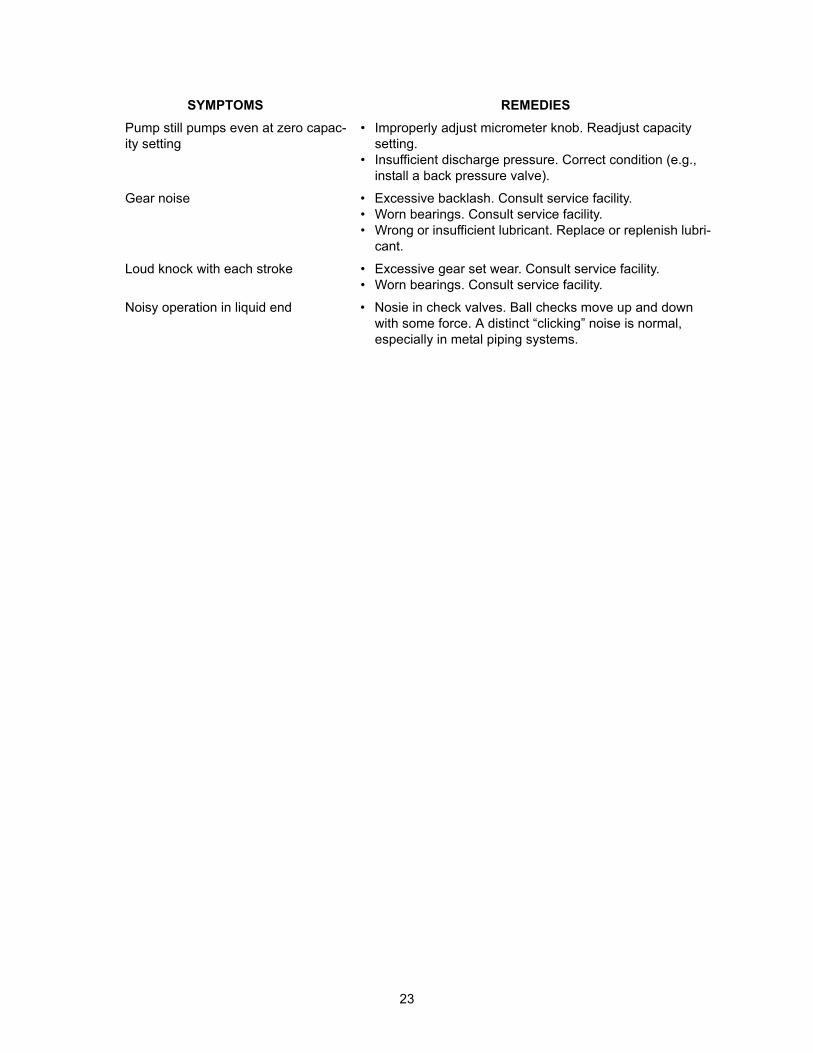
Pump still pumps even at zero capac-ity setting
• Improperly adjust micrometer knob. Readjust capacity setting.
• Insufficient discharge pressure. Correct condition (e.g., install a back pressure valve).
Gear noise • Excessive backlash. Consult service facility.• Worn bearings. Consult service facility.• Wrong or insufficient lubricant. Replace or replenish lubri-
cant.
Loud knock with each stroke • Excessive gear set wear. Consult service facility.• Worn bearings. Consult service facility.
Noisy operation in liquid end • Nosie in check valves. Ball checks move up and down with some force. A distinct “clicking” noise is normal, especially in metal piping systems.
SYMPTOMS REMEDIES
24
SECTION 6PARTS
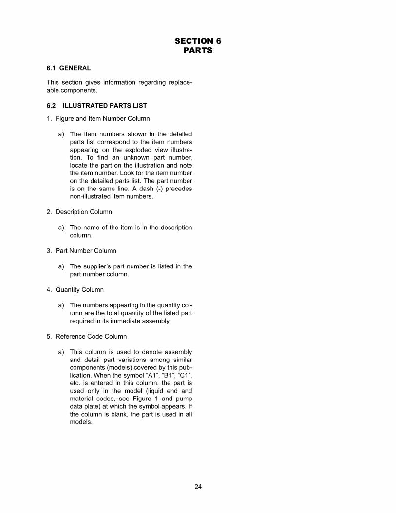
6.1 GENERAL
This section gives information regarding replace-able components.
6.2 ILLUSTRATED PARTS LIST
1. Figure and Item Number Column
a) The item numbers shown in the detailedparts list correspond to the item numbersappearing on the exploded view illustra-tion. To find an unknown part number,locate the part on the illustration and notethe item number. Look for the item numberon the detailed parts list. The part numberis on the same line. A dash (-) precedesnon-illustrated item numbers.
2. Description Column
a) The name of the item is in the descriptioncolumn.
3. Part Number Column
a) The supplier’s part number is listed in thepart number column.
4. Quantity Column
a) The numbers appearing in the quantity col-umn are the total quantity of the listed partrequired in its immediate assembly.
5. Reference Code Column
a) This column is used to denote assemblyand detail part variations among similarcomponents (models) covered by this pub-lication. When the symbol “A1”, “B1”, “C1”,etc. is entered in this column, the part isused only in the model (liquid end andmaterial codes, see Figure 1 and pumpdata plate) at which the symbol appears. Ifthe column is blank, the part is used in allmodels.
25
Figure 7 (Sheet 1 of 2). Series G Model G Drive Parts - Side View
26
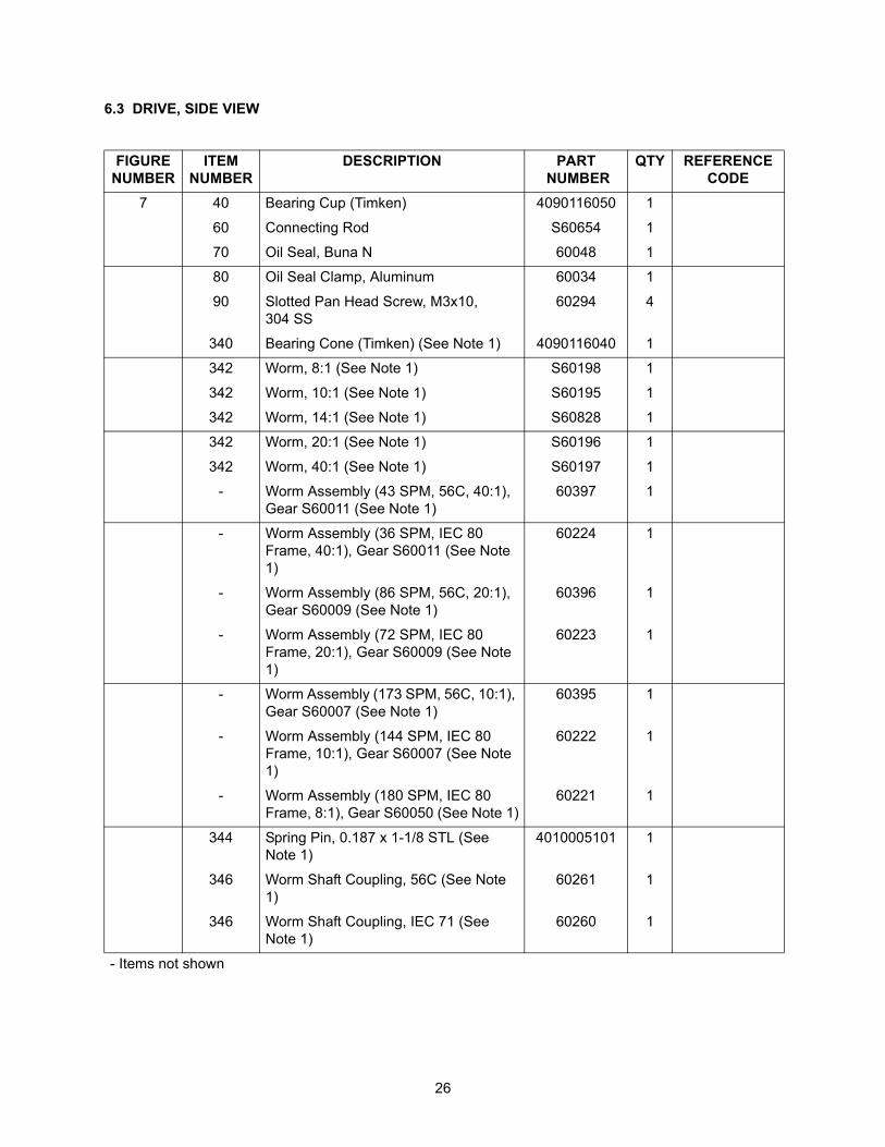
6.3 DRIVE, SIDE VIEW
FIGURE NUMBER
ITEM NUMBER
DESCRIPTION PART NUMBER
QTY REFERENCE CODE
7 40 Bearing Cup (Timken) 4090116050 1
60 Connecting Rod S60654 1
70 Oil Seal, Buna N 60048 1
80 Oil Seal Clamp, Aluminum 60034 1
90 Slotted Pan Head Screw, M3x10,304 SS
60294 4
340 Bearing Cone (Timken) (See Note 1) 4090116040 1
342 Worm, 8:1 (See Note 1) S60198 1
342 Worm, 10:1 (See Note 1) S60195 1
342 Worm, 14:1 (See Note 1) S60828 1
342 Worm, 20:1 (See Note 1) S60196 1
342 Worm, 40:1 (See Note 1) S60197 1
- Worm Assembly (43 SPM, 56C, 40:1), Gear S60011 (See Note 1)
60397 1
- Worm Assembly (36 SPM, IEC 80 Frame, 40:1), Gear S60011 (See Note 1)
60224 1
- Worm Assembly (86 SPM, 56C, 20:1), Gear S60009 (See Note 1)
60396 1
- Worm Assembly (72 SPM, IEC 80 Frame, 20:1), Gear S60009 (See Note 1)
60223 1
- Worm Assembly (173 SPM, 56C, 10:1), Gear S60007 (See Note 1)
60395 1
- Worm Assembly (144 SPM, IEC 80 Frame, 10:1), Gear S60007 (See Note 1)
60222 1
- Worm Assembly (180 SPM, IEC 80 Frame, 8:1), Gear S60050 (See Note 1)
60221 1
344 Spring Pin, 0.187 x 1-1/8 STL (See Note 1)
4010005101 1
346 Worm Shaft Coupling, 56C (See Note 1)
60261 1
346 Worm Shaft Coupling, IEC 71 (See Note 1)
60260 1
- Items not shown
27
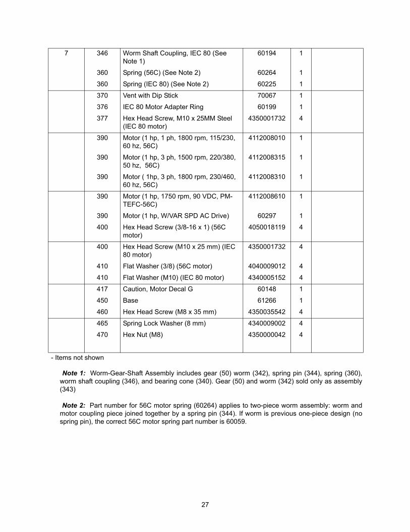
7 346 Worm Shaft Coupling, IEC 80 (See Note 1)
60194 1
360 Spring (56C) (See Note 2) 60264 1
360 Spring (IEC 80) (See Note 2) 60225 1
370 Vent with Dip Stick 70067 1
376 IEC 80 Motor Adapter Ring 60199 1
377 Hex Head Screw, M10 x 25MM Steel (IEC 80 motor)
4350001732 4
390 Motor (1 hp, 1 ph, 1800 rpm, 115/230, 60 hz, 56C)
4112008010 1
390 Motor (1 hp, 3 ph, 1500 rpm, 220/380, 50 hz, 56C)
4112008315 1
390 Motor ( 1hp, 3 ph, 1800 rpm, 230/460, 60 hz, 56C)
4112008310 1
390 Motor (1 hp, 1750 rpm, 90 VDC, PM-TEFC-56C)
4112008610 1
390 Motor (1 hp, W/VAR SPD AC Drive) 60297 1
400 Hex Head Screw (3/8-16 x 1) (56C motor)
4050018119 4
400 Hex Head Screw (M10 x 25 mm) (IEC 80 motor)
4350001732 4
410 Flat Washer (3/8) (56C motor) 4040009012 4
410 Flat Washer (M10) (IEC 80 motor) 4340005152 4
417 Caution, Motor Decal G 60148 1
450 Base 61266 1
460 Hex Head Screw (M8 x 35 mm) 4350035542 4
465 Spring Lock Washer (8 mm) 4340009002 4
470 Hex Nut (M8) 4350000042 4
- Items not shown
Note 1: Worm-Gear-Shaft Assembly includes gear (50) worm (342), spring pin (344), spring (360),worm shaft coupling (346), and bearing cone (340). Gear (50) and worm (342) sold only as assembly(343)
Note 2: Part number for 56C motor spring (60264) applies to two-piece worm assembly: worm andmotor coupling piece joined together by a spring pin (344). If worm is previous one-piece design (nospring pin), the correct 56C motor spring part number is 60059.
28
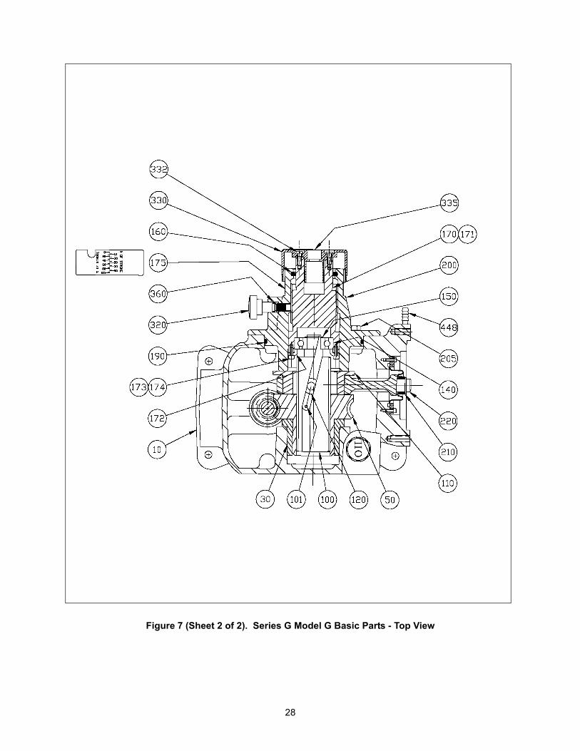
Figure 7 (Sheet 2 of 2). Series G Model G Basic Parts - Top View
29
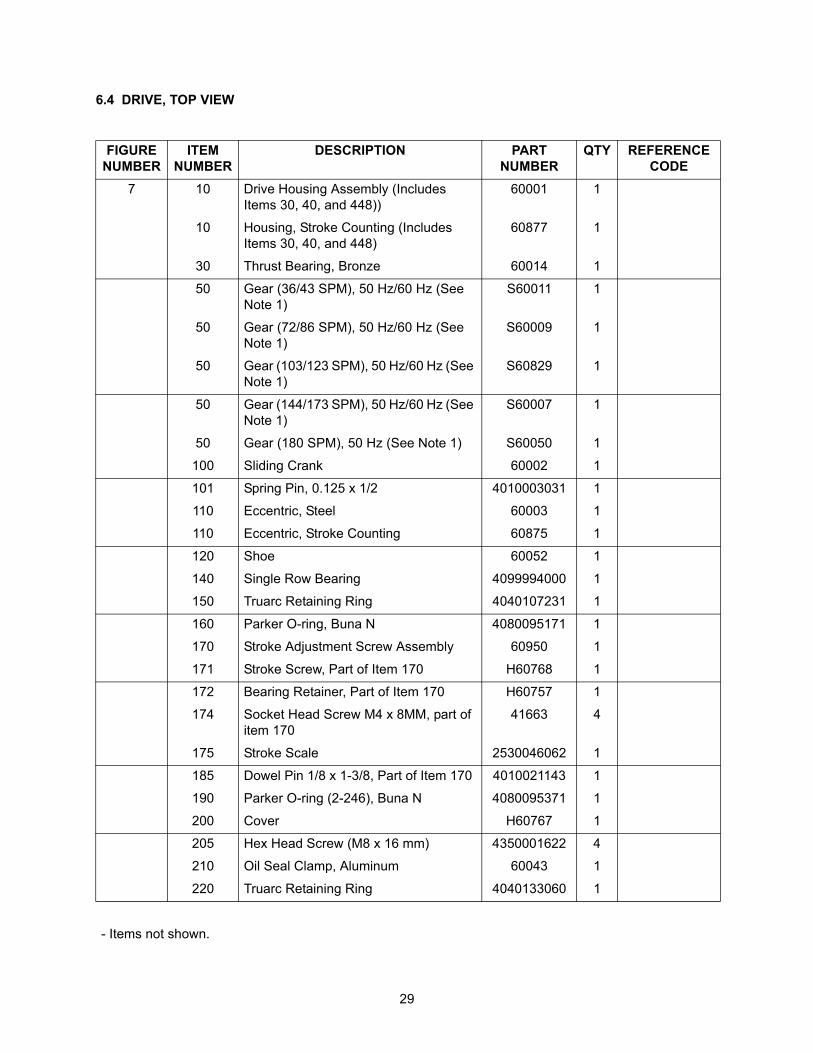
6.4 DRIVE, TOP VIEW
FIGURE NUMBER
ITEM NUMBER
DESCRIPTION PART NUMBER
QTY REFERENCE CODE
7 10 Drive Housing Assembly (Includes Items 30, 40, and 448))
60001 1
10 Housing, Stroke Counting (Includes Items 30, 40, and 448)
60877 1
30 Thrust Bearing, Bronze 60014 1
50 Gear (36/43 SPM), 50 Hz/60 Hz (See Note 1)
S60011 1
50 Gear (72/86 SPM), 50 Hz/60 Hz (See Note 1)
S60009 1
50 Gear (103/123 SPM), 50 Hz/60 Hz (See Note 1)
S60829 1
50 Gear (144/173 SPM), 50 Hz/60 Hz (See Note 1)
S60007 1
50 Gear (180 SPM), 50 Hz (See Note 1) S60050 1
100 Sliding Crank 60002 1
101 Spring Pin, 0.125 x 1/2 4010003031 1
110 Eccentric, Steel 60003 1
110 Eccentric, Stroke Counting 60875 1
120 Shoe 60052 1
140 Single Row Bearing 4099994000 1
150 Truarc Retaining Ring 4040107231 1
160 Parker O-ring, Buna N 4080095171 1
170 Stroke Adjustment Screw Assembly 60950 1
171 Stroke Screw, Part of Item 170 H60768 1
172 Bearing Retainer, Part of Item 170 H60757 1
174 Socket Head Screw M4 x 8MM, part of item 170
41663 4
175 Stroke Scale 2530046062 1
185 Dowel Pin 1/8 x 1-3/8, Part of Item 170 4010021143 1
190 Parker O-ring (2-246), Buna N 4080095371 1
200 Cover H60767 1
205 Hex Head Screw (M8 x 16 mm) 4350001622 4
210 Oil Seal Clamp, Aluminum 60043 1
220 Truarc Retaining Ring 4040133060 1
- Items not shown.
30
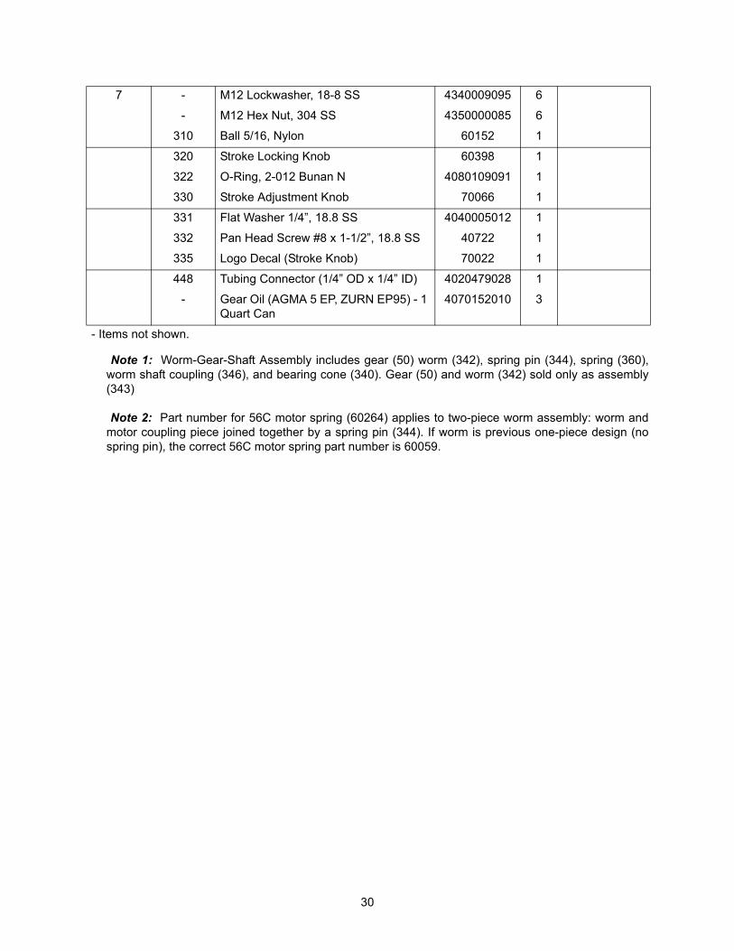
7 - M12 Lockwasher, 18-8 SS 4340009095 6
- M12 Hex Nut, 304 SS 4350000085 6
310 Ball 5/16, Nylon 60152 1
320 Stroke Locking Knob 60398 1
322 O-Ring, 2-012 Bunan N 4080109091 1
330 Stroke Adjustment Knob 70066 1
331 Flat Washer 1/4”, 18.8 SS 4040005012 1
332 Pan Head Screw #8 x 1-1/2”, 18.8 SS 40722 1
335 Logo Decal (Stroke Knob) 70022 1
448 Tubing Connector (1/4” OD x 1/4” ID) 4020479028 1
- Gear Oil (AGMA 5 EP, ZURN EP95) - 1 Quart Can
4070152010 3
- Items not shown.
Note 1: Worm-Gear-Shaft Assembly includes gear (50) worm (342), spring pin (344), spring (360),worm shaft coupling (346), and bearing cone (340). Gear (50) and worm (342) sold only as assembly(343)
Note 2: Part number for 56C motor spring (60264) applies to two-piece worm assembly: worm andmotor coupling piece joined together by a spring pin (344). If worm is previous one-piece design (nospring pin), the correct 56C motor spring part number is 60059.
31
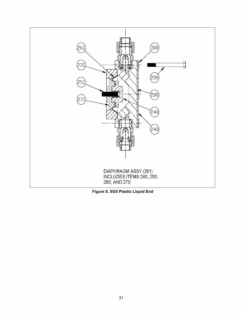
Figure 8. SG5 Plastic Liquid End
32
FIGURE NUMBER
ITEM NUMBER
DESCRIPTION PART NUMBER
QTY REFERENCE CODE
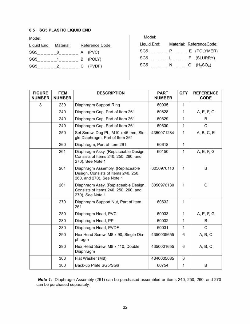
8 230 Diaphragm Support Ring 60035 1
240 Diaphragm Cap, Part of Item 261 60628 1 A, E, F, G
240 Diaphragm Cap, Part of Item 261 60629 1 B
240 Diaphragm Cap, Part of Item 261 60630 1 C
250 Set Screw, Dog Pt., M10 x 45 mm, Sin-gle Diaphragm, Part of Item 261
4350071284 1 A, B, C, E
260 Diaphragm, Part of Item 261 60618 1
261 Diaphragm Assy, (Replaceable Design, Consists of Items 240, 250, 260, and 270), See Note 1
60150 1 A, E, F, G
261 Diaphragm Assembly, (Replaceable Design, Consists of Items 240, 250, 260, and 270), See Note 1
3050976110 1 B
261 Diaphragm Assy, (Replaceable Design, Consists of Items 240, 250, 260, and 270), See Note 1
3050976130 1 C
270 Diaphragm Support Nut, Part of Item 261
60632 1
280 Diaphragm Head, PVC 60033 1 A, E, F, G
280 Diaphragm Head, PP 60032 1 B
280 Diaphragm Head, PVDF 60031 1 C
290 Hex Head Screw, M8 x 90, Single Dia-phragm
4350035655 6 A, B, C
290 Hex Head Screw, M8 x 110, Double Diaphragm
4350001655 6 A, B, C
300 Flat Washer (M8) 4340005085 6
300 Back-up Plate SG5/SG6 60754 1 B
6.5 SG5 PLASTIC LIQUID END
Model:
Liquid End: Material: Reference Code:
SG5_ _ _ _ _ _8_ _ _ _ _ _ A (PVC)
SG5_ _ _ _ _ _1_ _ _ _ _ _ B (POLY)
SG5_ _ _ _ _ _2_ _ _ _ _ _ C (PVDF)
Model:
Liquid End: Material: ReferenceCode:
SG5_ _ _ _ _ _ P_ _ _ _ _ E (POLYMER)
SG5_ _ _ _ _ _ L_ _ _ _ _ F (SLURRY)
SG5_ _ _ _ _ _ N_ _ _ _ _G (H2SO4)
Note 1: Diaphragm Assembly (261) can be purchased assembled or items 240, 250, 260, and 270can be purchased separately.
33
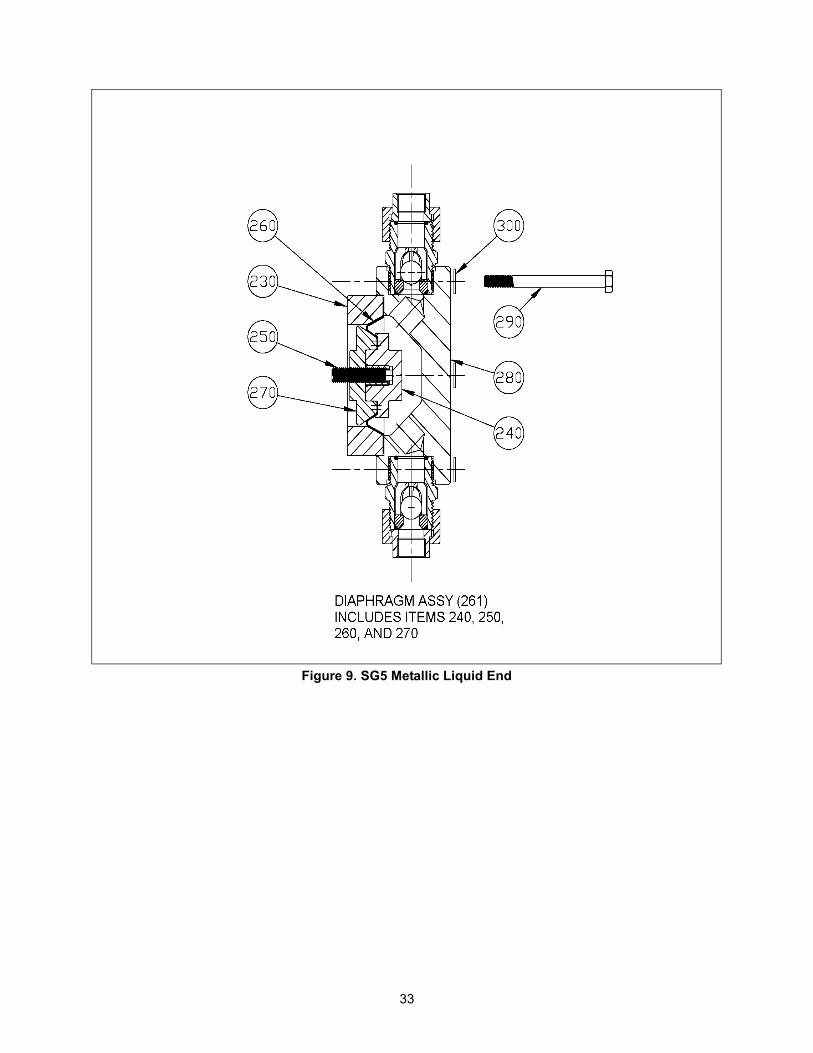
Figure 9. SG5 Metallic Liquid End
34
FIGURE NUMBER
ITEM NUMBER
DESCRIPTION PART NUMBER
QTY REFERENCE CODE
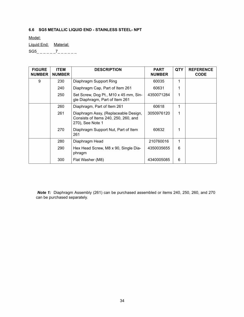
9 230 Diaphragm Support Ring 60035 1
240 Diaphragm Cap, Part of Item 261 60631 1
250 Set Screw, Dog Pt., M10 x 45 mm, Sin-gle Diaphragm, Part of Item 261
4350071284 1
260 Diaphragm, Part of Item 261 60618 1
261 Diaphragm Assy, (Replaceable Design, Consists of Items 240, 250, 260, and 270), See Note 1
3050976120 1
270 Diaphragm Support Nut, Part of Item 261
60632 1
280 Diaphragm Head 210760016 1
290 Hex Head Screw, M8 x 90, Single Dia-phragm
4350035655 6
300 Flat Washer (M8) 4340005085 6
6.6 SG5 METALLIC LIQUID END - STAINLESS STEEL- NPT
Model:
Liquid End: Material:
SG5_ _ _ _ _ _7_ _ _ _ _ _
Note 1: Diaphragm Assembly (261) can be purchased assembled or items 240, 250, 260, and 270can be purchased separately.
35
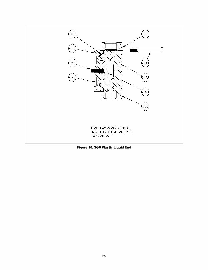
Figure 10. SG6 Plastic Liquid End
36
FIGURE NUMBER
ITEM NUMBER
DESCRIPTION PART NUMBER
QTY REFERENCE CODE
10 230 Diaphragm Support Ring 60070 1
240 Diaphragm Cap, Part of Item 261 60633 1 A, E, F, G
240 Diaphragm Cap, Part of Item 261 60634 1 B
240 Diaphragm Cap, Part of Item 261 60635 1 C
250 Set Screw, Dog Pt., M10 x 45 mm, Sin-gle Diaphragm, Part of Item 261
4350071284 1
260 Diaphragm, Part of Item 261 60624 1
261 Diaphragm Assy, (Replaceable Design, Consists of Items 240, 250, 260, and 270), See Note 1
60151 1 A, E, F, G
261 Diaphragm Assembly, (Replaceable Design, Consists of Items 240, 250, 260, and 270), See Note 1
3050976090 1 B
261 Diaphragm Assy, (Replaceable Design, Consists of Items 240, 250, 260, and 270), See Note 1
3050976230 1 C
270 Diaphragm Support Nut, Part of Item 261
60637 1
280 Diaphragm Head, PVC 60130 1 A, E, F, G
280 Diaphragm Head, PP 60883 1 B
280 Diaphragm Head, PVDF 60068 1 C
290 Hex Head Screw, M8 x 90, Single Dia-phragm
4350035655 6
300 Flat Washer (M8) 4340005085 6
300 Back-up Plate SG5/SG6 60754 1 B
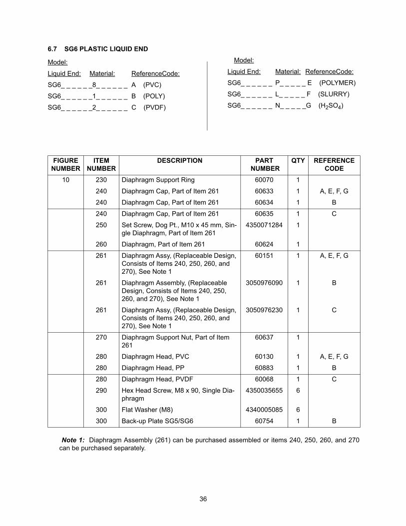
6.7 SG6 PLASTIC LIQUID END
Model:
Liquid End: Material: ReferenceCode:
SG6_ _ _ _ _ _8_ _ _ _ _ _ A (PVC)
SG6_ _ _ _ _ _1_ _ _ _ _ _ B (POLY)
SG6_ _ _ _ _ _2_ _ _ _ _ _ C (PVDF)
Model:
Liquid End: Material: ReferenceCode:
SG6_ _ _ _ _ _ P_ _ _ _ _ E (POLYMER)
SG6_ _ _ _ _ _ L_ _ _ _ _ F (SLURRY)
SG6_ _ _ _ _ _ N_ _ _ _ _G (H2SO4)
Note 1: Diaphragm Assembly (261) can be purchased assembled or items 240, 250, 260, and 270can be purchased separately.
37
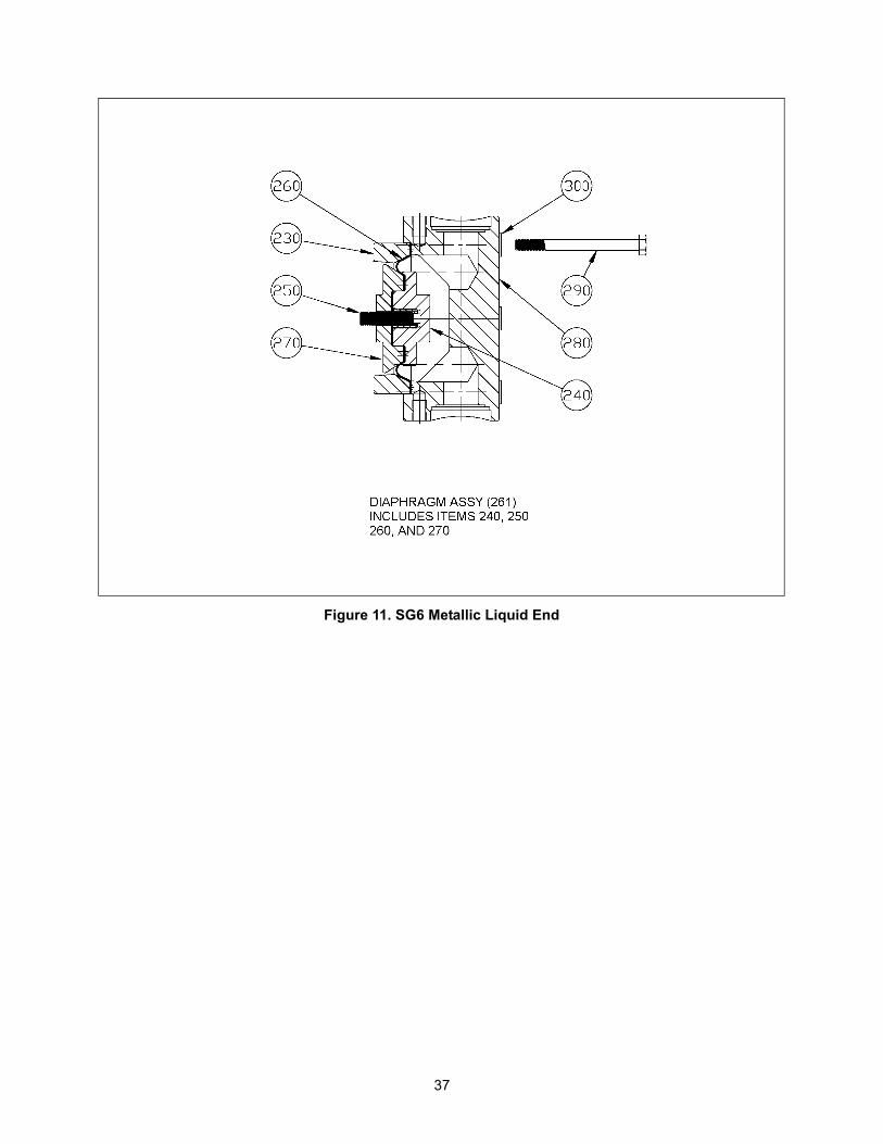
Figure 11. SG6 Metallic Liquid End
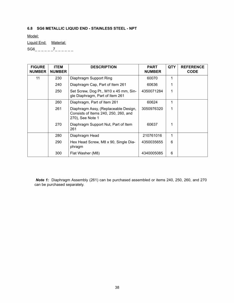
38
FIGURE NUMBER
ITEM NUMBER
DESCRIPTION PART NUMBER
QTY REFERENCE CODE
11 230 Diaphragm Support Ring 60070 1
240 Diaphragm Cap, Part of Item 261 60636 1
250 Set Screw, Dog Pt., M10 x 45 mm, Sin-gle Diaphragm, Part of Item 261
4350071284 1
260 Diaphragm, Part of Item 261 60624 1
261 Diaphragm Assy, (Replaceable Design, Consists of Items 240, 250, 260, and 270), See Note 1
3050976320 1
270 Diaphragm Support Nut, Part of Item 261
60637 1
280 Diaphragm Head 210761016 1
290 Hex Head Screw, M8 x 90, Single Dia-phragm
4350035655 6
300 Flat Washer (M8) 4340005085 6
6.8 SG6 METALLIC LIQUID END - STAINLESS STEEL - NPT
Model:
Liquid End: Material:
SG6_ _ _ _ _ _7_ _ _ _ _ _
Note 1: Diaphragm Assembly (261) can be purchased assembled or items 240, 250, 260, and 270can be purchased separately.
39
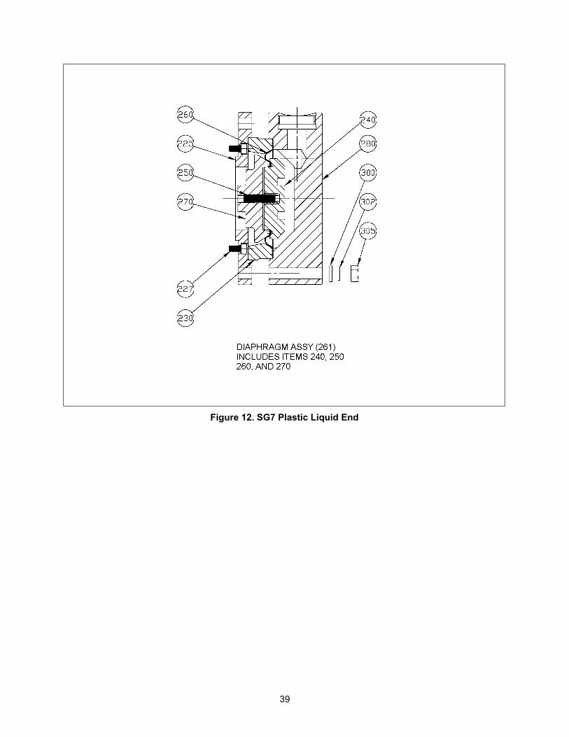
Figure 12. SG7 Plastic Liquid End
40
FIGURE NUMBER
ITEM NUMBER
DESCRIPTION PART NUMBER
QTY REFERENCE CODE
12 225 Adapter Ring, Aluminum 60165 1
227 Socket Head Screw (M8 x 25 mm), Zinc PLT
4350003473 6
230 Diaphragm Support Ring 60159 1
240 Diaphragm Cap, Part of Item 261 60638 1 A, E, F, G
240 Diaphragm Cap, Part of Item 261 60639 1 B
240 Diaphragm Cap, Part of Item 261 60640 1 C
250 Set Screw, Dog Pt., M10 x 70 mm, Sin-gle Diaphragm, Part of Item 261
4350071334 1 A, B, C, F
260 Diaphragm, Part of Item 261 60162 1
261 Diaphragm Assy, (Replaceable Design, Consists of Items 240, 250, 260, and 270), See Note 1
60226 1 A, F, G
261 Diaphragm Assembly, (Replaceable Design, Consists of Items 240, 250, 260, and 270), See Note 1
60227 1 B
261 Diaphragm Assy, (Replaceable Design, Consists of Items 240, 250, 260, and 270), See Note 1
60229 1 C
270 Diaphragm Support Nut, Part of Item 261
60642 1
280 Diaphragm Head 60171 1 A, E, F, G
280 Diaphragm Head 60174 1 B, C
290 Hex Head Screw, M8 x 90, Single Dia-phragm
4350036035 6 A, B, C
300 Flat Washer (M8) 4340055073 6
6.9 SG7 PLASTIC LIQUID END
Model:
Liquid End: Material: ReferenceCode:
SG7_ _ _ _ _ _8_ _ _ _ _ _ A (PVC)
SG7_ _ _ _ _ _1_ _ _ _ _ _ B (POLY)
SG7_ _ _ _ _ _2_ _ _ _ _ _ C (PVDF)
Model:
Liquid End: Material: ReferenceCode:
SG7_ _ _ _ _ _ P_ _ _ _ _ E (POLYMER)
SG7_ _ _ _ _ _ L_ _ _ _ _ F (SLURRY)
SG7_ _ _ _ _ _ N_ _ _ _ _G (H2SO4)
Note 1: Diaphragm Assembly (261) can be purchased assembled or items 240, 250, 260, and 270can be purchased separately.
41
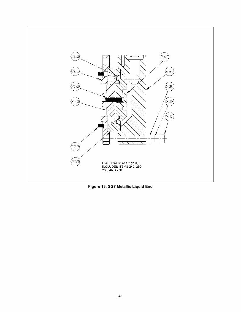
Figure 13. SG7 Metallic Liquid End
42
FIGURE NUMBER
ITEM NUMBER
DESCRIPTION PART NUMBER
QTY REFERENCE CODE
13 225 Adapter Ring, Aluminum 60165 1
227 Socket Head Screw (M8 x 25 mm), Zinc PLT
4350003473 6
230 Diaphragm Support Ring 60159 1
240 Diaphragm Cap, Part of Item 261 60641 1
250 Set Screw, Dog Pt., M10 x 70 mm, Sin-gle Diaphragm, Part of Item 261
4350071334 1
260 Diaphragm, Part of Item 261 60162 1
261 Diaphragm Assy, (Replaceable Design, Consists of Items 240, 250, 260, and 270), See Note 1
60228 1
270 Diaphragm Support Nut, Part of Item 261
60642 1
280 Diaphragm Head 60180 1
290 Hex Head Screw, M12 x 130, Single Diaphragm
4350036035 6
300 Flat Washer (M12) 4340055073 6
6.10 SG7 METALLIC LIQUID END - STAINLESS STEEL - NPT
Model:
Liquid End: Material:
SG7_ _ _ _ _ _7_ _ _ _ _ _
43
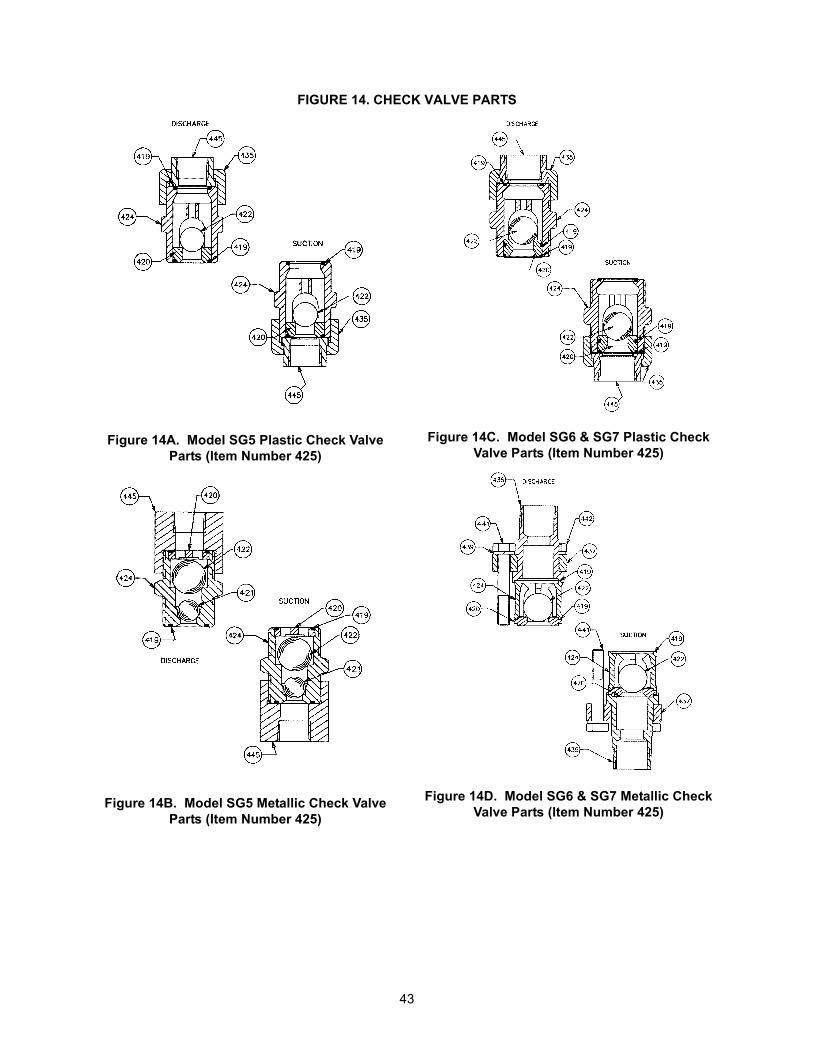
FIGURE 14. CHECK VALVE PARTS
Figure 14A. Model SG5 Plastic Check Valve Parts (Item Number 425)
Figure 14B. Model SG5 Metallic Check Valve Parts (Item Number 425)
Figure 14C. Model SG6 & SG7 Plastic Check Valve Parts (Item Number 425)
Figure 14D. Model SG6 & SG7 Metallic Check Valve Parts (Item Number 425)
44
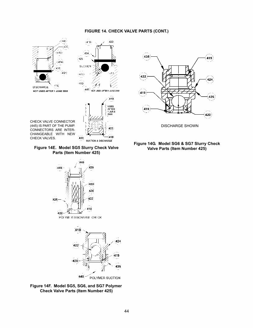
FIGURE 14. CHECK VALVE PARTS (CONT.)
Figure 14E. Model SG5 Slurry Check Valve Parts (Item Number 425)
Figure 14F. Model SG5, SG6, and SG7 Polymer Check Valve Parts (Item Number 425)
Figure 14G. Model SG6 & SG7 Slurry Check Valve Parts (Item Number 425)
DISCHARGE SHOWNCHECK VALVE CONNECTOR(445) IS PART OF THE PUMP.CONNECTORS ARE INTER-CHANGEABLE WITH NEWCHECK VALVES.
45
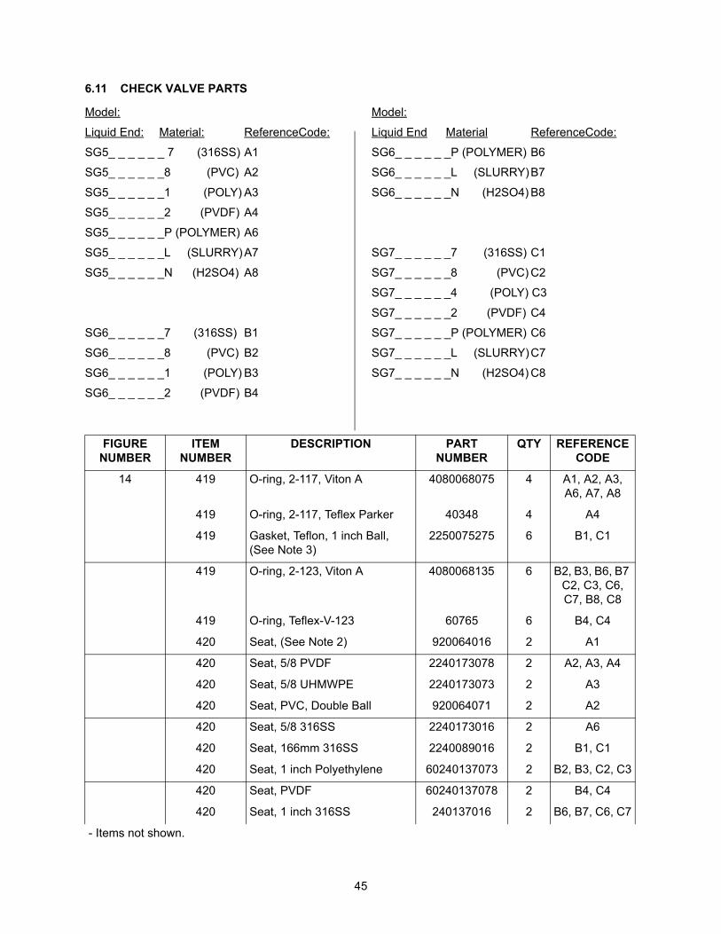
6.11 CHECK VALVE PARTS
Model:
Liquid End: Material: ReferenceCode:
SG5_ _ _ _ _ _ 7 (316SS) A1
SG5_ _ _ _ _ _8 (PVC) A2
SG5_ _ _ _ _ _1 (POLY) A3
SG5_ _ _ _ _ _2 (PVDF) A4
SG5_ _ _ _ _ _P (POLYMER) A6
SG5_ _ _ _ _ _L (SLURRY)A7
SG5_ _ _ _ _ _N (H2SO4) A8
SG6_ _ _ _ _ _7 (316SS) B1
SG6_ _ _ _ _ _8 (PVC) B2
SG6_ _ _ _ _ _1 (POLY) B3
SG6_ _ _ _ _ _2 (PVDF) B4
Model:
Liquid End Material ReferenceCode:
SG6_ _ _ _ _ _P (POLYMER) B6
SG6_ _ _ _ _ _L (SLURRY)B7
SG6_ _ _ _ _ _N (H2SO4) B8
SG7_ _ _ _ _ _7 (316SS) C1
SG7_ _ _ _ _ _8 (PVC) C2
SG7_ _ _ _ _ _4 (POLY) C3
SG7_ _ _ _ _ _2 (PVDF) C4
SG7_ _ _ _ _ _P (POLYMER) C6
SG7_ _ _ _ _ _L (SLURRY)C7
SG7_ _ _ _ _ _N (H2SO4) C8
FIGURE NUMBER
ITEMNUMBER
DESCRIPTION PARTNUMBER
QTY REFERENCE CODE
14 419 O-ring, 2-117, Viton A 4080068075 4 A1, A2, A3, A6, A7, A8
419 O-ring, 2-117, Teflex Parker 40348 4 A4
419 Gasket, Teflon, 1 inch Ball, (See Note 3)
2250075275 6 B1, C1
419 O-ring, 2-123, Viton A 4080068135 6 B2, B3, B6, B7 C2, C3, C6, C7, B8, C8
419 O-ring, Teflex-V-123 60765 6 B4, C4
420 Seat, (See Note 2) 920064016 2 A1
420 Seat, 5/8 PVDF 2240173078 2 A2, A3, A4
420 Seat, 5/8 UHMWPE 2240173073 2 A3
420 Seat, PVC, Double Ball 920064071 2 A2
420 Seat, 5/8 316SS 2240173016 2 A6
420 Seat, 166mm 316SS 2240089016 2 B1, C1
420 Seat, 1 inch Polyethylene 60240137073 2 B2, B3, C2, C3
420 Seat, PVDF 60240137078 2 B4, C4
420 Seat, 1 inch 316SS 240137016 2 B6, B7, C6, C7
- Items not shown.
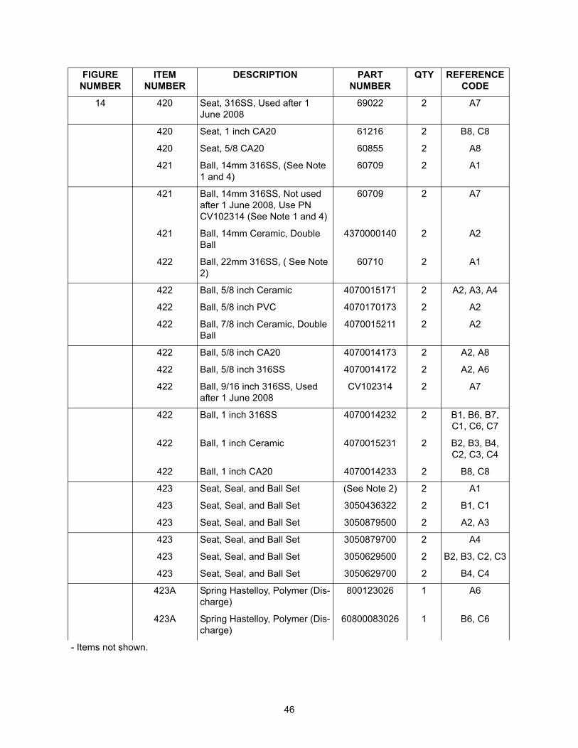
46
14 420 Seat, 316SS, Used after 1 June 2008
69022 2 A7
420 Seat, 1 inch CA20 61216 2 B8, C8
420 Seat, 5/8 CA20 60855 2 A8
421 Ball, 14mm 316SS, (See Note 1 and 4)
60709 2 A1
421 Ball, 14mm 316SS, Not used after 1 June 2008, Use PN CV102314 (See Note 1 and 4)
60709 2 A7
421 Ball, 14mm Ceramic, Double Ball
4370000140 2 A2
422 Ball, 22mm 316SS, ( See Note 2)
60710 2 A1
422 Ball, 5/8 inch Ceramic 4070015171 2 A2, A3, A4
422 Ball, 5/8 inch PVC 4070170173 2 A2
422 Ball, 7/8 inch Ceramic, Double Ball
4070015211 2 A2
422 Ball, 5/8 inch CA20 4070014173 2 A2, A8
422 Ball, 5/8 inch 316SS 4070014172 2 A2, A6
422 Ball, 9/16 inch 316SS, Used after 1 June 2008
CV102314 2 A7
422 Ball, 1 inch 316SS 4070014232 2 B1, B6, B7, C1, C6, C7
422 Ball, 1 inch Ceramic 4070015231 2 B2, B3, B4, C2, C3, C4
422 Ball, 1 inch CA20 4070014233 2 B8, C8
423 Seat, Seal, and Ball Set (See Note 2) 2 A1
423 Seat, Seal, and Ball Set 3050436322 2 B1, C1
423 Seat, Seal, and Ball Set 3050879500 2 A2, A3
423 Seat, Seal, and Ball Set 3050879700 2 A4
423 Seat, Seal, and Ball Set 3050629500 2 B2, B3, C2, C3
423 Seat, Seal, and Ball Set 3050629700 2 B4, C4
423A Spring Hastelloy, Polymer (Dis-charge)
800123026 1 A6
423A Spring Hastelloy, Polymer (Dis-charge)
60800083026 1 B6, C6
FIGURE NUMBER
ITEMNUMBER
DESCRIPTION PARTNUMBER
QTY REFERENCE CODE
- Items not shown.
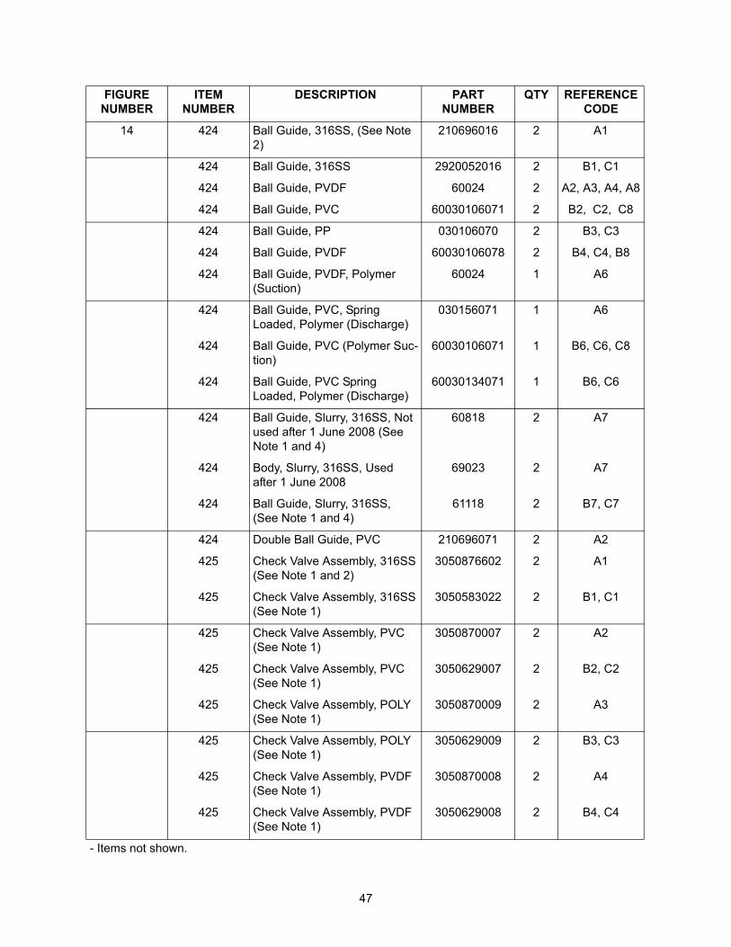
47
14 424 Ball Guide, 316SS, (See Note 2)
210696016 2 A1
424 Ball Guide, 316SS 2920052016 2 B1, C1
424 Ball Guide, PVDF 60024 2 A2, A3, A4, A8
424 Ball Guide, PVC 60030106071 2 B2, C2, C8
424 Ball Guide, PP 030106070 2 B3, C3
424 Ball Guide, PVDF 60030106078 2 B4, C4, B8
424 Ball Guide, PVDF, Polymer (Suction)
60024 1 A6
424 Ball Guide, PVC, Spring Loaded, Polymer (Discharge)
030156071 1 A6
424 Ball Guide, PVC (Polymer Suc-tion)
60030106071 1 B6, C6, C8
424 Ball Guide, PVC Spring Loaded, Polymer (Discharge)
60030134071 1 B6, C6
424 Ball Guide, Slurry, 316SS, Not used after 1 June 2008 (See Note 1 and 4)
60818 2 A7
424 Body, Slurry, 316SS, Used after 1 June 2008
69023 2 A7
424 Ball Guide, Slurry, 316SS, (See Note 1 and 4)
61118 2 B7, C7
424 Double Ball Guide, PVC 210696071 2 A2
425 Check Valve Assembly, 316SS(See Note 1 and 2)
3050876602 2 A1
425 Check Valve Assembly, 316SS(See Note 1)
3050583022 2 B1, C1
425 Check Valve Assembly, PVC(See Note 1)
3050870007 2 A2
425 Check Valve Assembly, PVC(See Note 1)
3050629007 2 B2, C2
425 Check Valve Assembly, POLY(See Note 1)
3050870009 2 A3
425 Check Valve Assembly, POLY(See Note 1)
3050629009 2 B3, C3
425 Check Valve Assembly, PVDF(See Note 1)
3050870008 2 A4
425 Check Valve Assembly, PVDF(See Note 1)
3050629008 2 B4, C4
FIGURE NUMBER
ITEMNUMBER
DESCRIPTION PARTNUMBER
QTY REFERENCE CODE
- Items not shown.
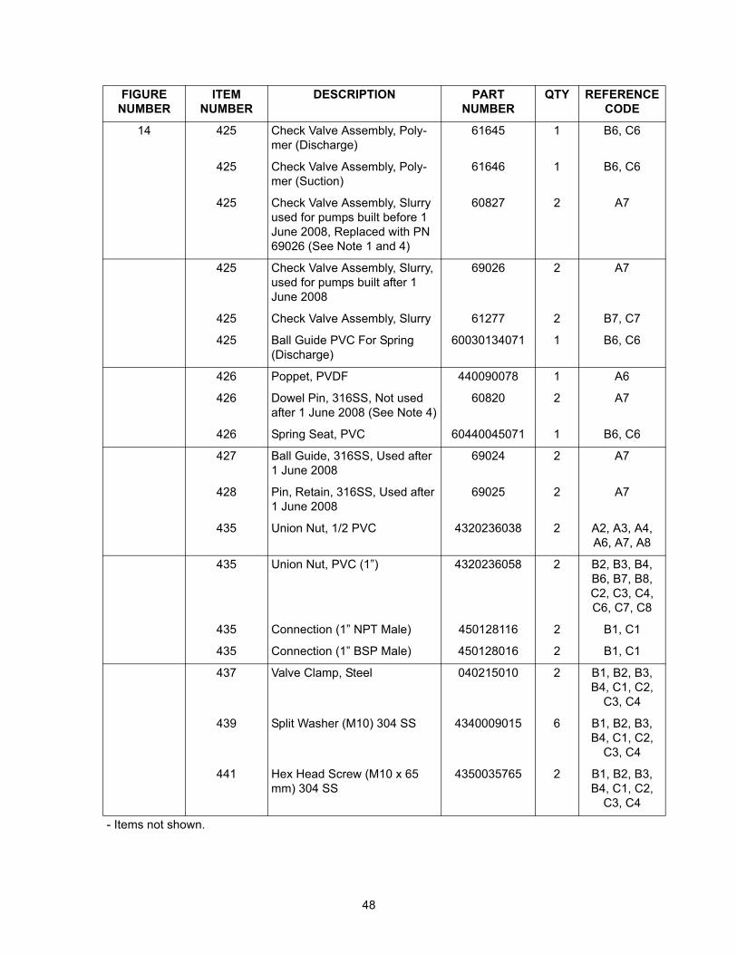
48
14 425 Check Valve Assembly, Poly-mer (Discharge)
61645 1 B6, C6
425 Check Valve Assembly, Poly-mer (Suction)
61646 1 B6, C6
425 Check Valve Assembly, Slurry used for pumps built before 1 June 2008, Replaced with PN 69026 (See Note 1 and 4)
60827 2 A7
425 Check Valve Assembly, Slurry, used for pumps built after 1 June 2008
69026 2 A7
425 Check Valve Assembly, Slurry 61277 2 B7, C7
425 Ball Guide PVC For Spring (Discharge)
60030134071 1 B6, C6
426 Poppet, PVDF 440090078 1 A6
426 Dowel Pin, 316SS, Not used after 1 June 2008 (See Note 4)
60820 2 A7
426 Spring Seat, PVC 60440045071 1 B6, C6
427 Ball Guide, 316SS, Used after 1 June 2008
69024 2 A7
428 Pin, Retain, 316SS, Used after 1 June 2008
69025 2 A7
435 Union Nut, 1/2 PVC 4320236038 2 A2, A3, A4, A6, A7, A8
435 Union Nut, PVC (1”) 4320236058 2 B2, B3, B4, B6, B7, B8, C2, C3, C4, C6, C7, C8
435 Connection (1” NPT Male) 450128116 2 B1, C1
435 Connection (1” BSP Male) 450128016 2 B1, C1
437 Valve Clamp, Steel 040215010 2 B1, B2, B3, B4, C1, C2,
C3, C4
439 Split Washer (M10) 304 SS 4340009015 6 B1, B2, B3, B4, C1, C2,
C3, C4
441 Hex Head Screw (M10 x 65 mm) 304 SS
4350035765 2 B1, B2, B3, B4, C1, C2,
C3, C4
FIGURE NUMBER
ITEMNUMBER
DESCRIPTION PARTNUMBER
QTY REFERENCE CODE
- Items not shown.
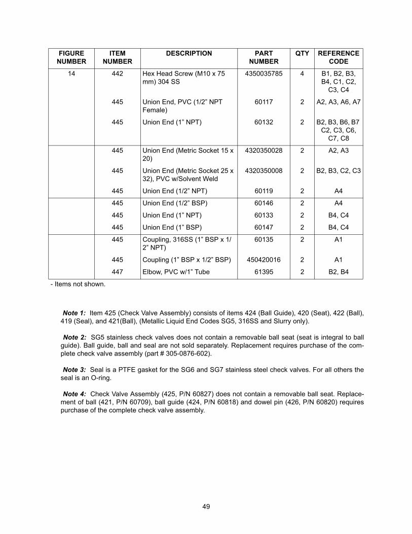
49
Note 1: Item 425 (Check Valve Assembly) consists of items 424 (Ball Guide), 420 (Seat), 422 (Ball),419 (Seal), and 421(Ball), (Metallic Liquid End Codes SG5, 316SS and Slurry only).
Note 2: SG5 stainless check valves does not contain a removable ball seat (seat is integral to ballguide). Ball guide, ball and seal are not sold separately. Replacement requires purchase of the com-plete check valve assembly (part # 305-0876-602).
Note 3: Seal is a PTFE gasket for the SG6 and SG7 stainless steel check valves. For all others theseal is an O-ring.
Note 4: Check Valve Assembly (425, P/N 60827) does not contain a removable ball seat. Replace-ment of ball (421, P/N 60709), ball guide (424, P/N 60818) and dowel pin (426, P/N 60820) requirespurchase of the complete check valve assembly.
14 442 Hex Head Screw (M10 x 75 mm) 304 SS
4350035785 4 B1, B2, B3, B4, C1, C2,
C3, C4
445 Union End, PVC (1/2” NPT Female)
60117 2 A2, A3, A6, A7
445 Union End (1” NPT) 60132 2 B2, B3, B6, B7 C2, C3, C6,
C7, C8
445 Union End (Metric Socket 15 x 20)
4320350028 2 A2, A3
445 Union End (Metric Socket 25 x 32), PVC w/Solvent Weld
4320350008 2 B2, B3, C2, C3
445 Union End (1/2” NPT) 60119 2 A4
445 Union End (1/2” BSP) 60146 2 A4
445 Union End (1” NPT) 60133 2 B4, C4
445 Union End (1” BSP) 60147 2 B4, C4
445 Coupling, 316SS (1” BSP x 1/2” NPT)
60135 2 A1
445 Coupling (1” BSP x 1/2” BSP) 450420016 2 A1
447 Elbow, PVC w/1” Tube 61395 2 B2, B4
FIGURE NUMBER
ITEMNUMBER
DESCRIPTION PARTNUMBER
QTY REFERENCE CODE
- Items not shown.

201 Ivyland Road • Ivyland, PA 18974 • (215) 293-0401 • Fax: (215) 293-0445 • www.lmipumps,comE-mail: [email protected]
Related Documents