Grayhill, Inc. • 561 Hillgrove Avenue • LaGrange, Illinois 60525-5997 • USA • Phone: 708-354-1040 • Fax: 708-354-2820 • www.grayhill.com Rotary Switches Single Deck Rotary Switches SPECIFICATIONS Electrical Rating Rated: To make and break the following loads: 1 amp at 115 Vac resistive; 0.5 amp at 220 Vac resistive; 1/4 amp, 115 Vac inductive; 1/50 amp, 115 Vdc inductive, 1/10 amp, 6 to 28 Vdc inductive; 1/10 amp, 115 Vdc resistive; 1 amp, 6 to 28 Vdc resistive; to carry 10 amps continuously. Contact Resistance: 10 milliohms initial. After 25,000 cycles of operation 20 milliohms maximum. Insulation Resistance: 50,000 Mohms minimum initially Voltage Breakdown: 1,000 Vac (500 Vac, or better after most environmental tests). Life Expectancy: 100,000 mechanical cycles of operation normally. NOTE: Actual life is determined by a number of factors, including electrical loading, rate of rotation, and environment, as well as maximum contact resistance, minimum insulation resistance, and minimum voltage breakdown required at the end of life. Materials and Finishes Switch Base: Melamine per MIL-M-14 (ASTM- D-5948) Cover, Stop Washers, Bushing: Brass, tin/ zinc-plated Grayhill part number and date code marked on label. Customer part number marked on request. DIMENSIONS in inches (and millimeters) Circuit Diagram (Switch is viewed from shaft end.) Note: Common Terminal is located above Base Terminal 10. .823 ± .020 (20,90 ± 0,51) DIA. .219 ± .005 (5,56 ± 0,13) 36° ± 5° .564 ± .020 (14,33 ± 0,51) COMMON 7 8 9 10 1 2 3 4 6 5 C L OF BUSHING KEYWAY ONE POLE C 1 SERIES 5000 1" Diameter, 1 Amp, . 470" Behind Panel FEATURES • High Quality at a Low Price • High Contact Force Provides Stable Electrical and Mechanical Operation • Proven Reliability in Thousands of Applications Mounting Nut: Brass, tin/zinc-plated or stainless steel Retaining Rings, Stop Arms, and Thrust Washers: Stainless steel Shaft: Stainless steel Terminals (except common): Brass, tin plated Rotor Contact: Phosphor bronze, silver-plated .0003" minimum Stator (Base) Contact: Brass, silver-plated .0003" minimum Common Plate: Brass, silver-plated .0003" minimum Rotor Mounting Plate: Nylon fabric-based laminated Phenolic per MIL-T-1 5047. Additional Characteristics Stop Strength: 12 in-lbs Rotational Torque: 12 in-ozs. Contacts: Shorting or non-shorting wiping contacts with over 500 grams contact force. Shaft Flat Orientation: Opposite point of contact (See circuit diagram.) Environmental: These switches have passed the following environmental testing: Altitude and temperature; 100 hour salt spray; Vibration 10 to 500 cps; Shock 30-G; Humidity; Fungus. Detent: A formed spring operating against a formed wave washer. STANDARD OPTIONS Special Terminals Not available through distributors. ORDERING INFORMATION The Series 5000 switches are single deck, one pole switches of two to 10 positions. Ten position switches have continuous rotation. Ten position fixed stop switches are available by special order. The part number is 05001-XX with the number of positions required (02,03, etc.) listed in place of the XX. Complete part number by adding N for non-shorting contacts or S for shorting contacts. RECOMMENDED PANEL CUTOUT 3/8-32UNEF-2A THREAD BUSHING KEYWAY .066 ± .002 (1,68 ± 0,05) WIDE .036 ± .005 (0,91 ± 0,13) DEEP FROM THE .375 (9,53) DIAMETER .490 ± .020 (12,45 ± 0,51) 1.015 ± .015 (25,78 ± 0,38) DIA. TERMINAL 9 IN LINE WITH KEYWAY .823 ± .015 (20,9 ± 0,38) .250 + .001/ – .002 (6,35 + 0,03/ – 0,05) DIA. .250 ± .020 (6,35 ± 0.51) .250 ± .020 (6,35 ± 0.51) .312 ± .020 (7,93 ± 0,51) +.00 5 DIA. .375 -.000 +.003 . 1 545 -.000 060 + 0 002 -.

Welcome message from author
This document is posted to help you gain knowledge. Please leave a comment to let me know what you think about it! Share it to your friends and learn new things together.
Transcript
Grayhil l , Inc. • 561 Hil lgrove Avenue • LaGrange, I l l inois 60525-5997 • USA • Phone: 708-354-1040 • Fax: 708-354-2820 • www.grayhil l .com
Rotary S
witches
Single Deck Rotary Switches
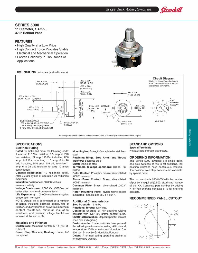
SPECIFICAtIONSElectrical RatingRated: To make and break the following loads: 1 amp at 115 Vac resistive; 0.5 amp at 220 Vac resistive; 1/4 amp, 115 Vac inductive; 1/50 amp, 115 Vdc inductive, 1/10 amp, 6 to 28 Vdc inductive; 1/10 amp, 115 Vdc resistive; 1 amp, 6 to 28 Vdc resistive; to carry 10 amps continuously.Contact Resistance: 10 milliohms initial. After 25,000 cycles of operation 20 milliohms maximum.Insulation Resistance: 50,000 Mohms minimum initiallyvoltage Breakdown: 1,000 Vac (500 Vac, or better after most environmental tests).Life Expectancy: 100,000 mechanical cycles of operation normally.NOTE: Actual life is determined by a number of factors, including electrical loading, rate of rotation, and environment, as well as maximum contact resistance, minimum insulation resistance, and minimum voltage breakdown required at the end of life.
Materials and FinishesSwitch Base: Melamine per MIL-M-14 (ASTM-D-5948)Cover, Stop washers, Bushing: Brass, tin/zinc-plated
Grayhill part number and date code marked on label. Customer part number marked on request.
DIMENSIONS in inches (and millimeters)
Circuit Diagram(Switch is viewed from shaft end.)Note: Common Terminal is located above Base Terminal 10.
.823 ± .020(20,90 ± 0,51)
DIA.
.219 ± .005(5,56 ± 0,13)
36° ± 5°
.564 ± .020(14,33 ± 0,51)
COMMON
7 89
10
123
4
6
5
C L OF BUSHINGKEYWAY
ONE POLE
C1
SERIES 50001" Diameter, 1 Amp, . 470" Behind Panel
FEAtuRES• HighQualityataLowPrice• HighContactForceProvidesStable
Electrical and Mechanical Operation• ProvenReliabilityinThousandsof
Applications
Mounting Nut:Brass,tin/zinc-platedorstainlesssteelRetaining Rings, Stop Arms, and thrust washers: Stainless steelShaft: Stainless steelterminals (except common): Brass, tin platedRotor Contact:Phosphorbronze,silver-plated.0003" minimumStator (Base) Contact: Brass, silver-plated .0003" minimumCommon Plate: Brass, silver-plated .0003" minimumRotor Mounting Plate: Nylon fabric-based laminated Phenolic per MIL-T-1 5047.
Additional CharacteristicsStop Strength: 12 in-lbsRotational torque:12in-ozs.Contacts: Shorting or non-shorting wiping contacts with over 500 grams contact force.Shaft Flat Orientation: Opposite point of contact (See circuit diagram.)Environmental: These switches have passed the following environmental testing: Altitude and temperature; 100 hour salt spray; Vibration 10 to 500 cps; Shock 30-G; Humidity; Fungus.Detent: A formed spring operating against a formed wave washer.
StANDARD OPtIONSSpecial terminalsNot available through distributors.
ORDERINg INFORMAtIONThe Series 5000 switches are single deck, one pole switches of two to 10 positions. Ten position switches have continuous rotation. Ten position fixed stop switches are available by special order.
The part number is 05001-XX with the number of positions required (02,03, etc.) listed in place of the XX. Complete part number by adding N for non-shorting contacts or S for shorting contacts.
RECOMMENDED PANEL CUTOUT
3/8-32UNEF-2ATHREAD
BUSHING KEYWAY.066 ± .002 (1,68 ± 0,05) WIDE.036 ± .005 (0,91 ± 0,13) DEEP FROM THE .375 (9,53) DIAMETER
.490 ± .020(12,45 ± 0,51)
1.015 ± .015(25,78 ± 0,38)
DIA.
TE
RM
INA
L 9
IN L
INE
WIT
H K
EY
WA
Y
.823 ± .015(20,9 ± 0,38)
.250 + .001/ – .002(6,35 + 0,03/ – 0,05) DIA.
.250 ± .020 (6,35 ± 0.51)
.250 ± .020 (6,35 ± 0.51)
.312 ± .020(7,93 ± 0,51)
+.005
DIA..375 -.000
+.003 . 1545 -.000
060
+
0
002 - .
Grayhil l , Inc. • 561 Hil lgrove Avenue • LaGrange, I l l inois 60525-5997 • USA • Phone: 708-354-1040 • Fax: 708-354-2820 • www.grayhil l .com
Rotary S
witches
Multi-Deck Rotary Switches
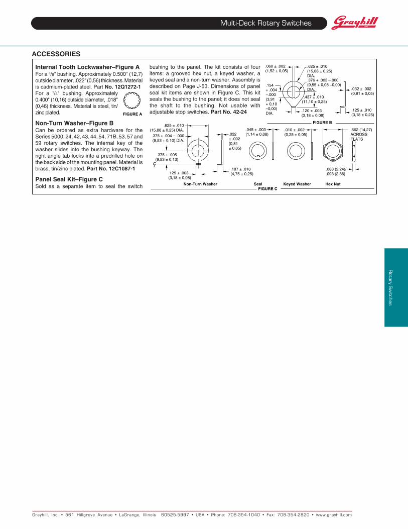
ACCESSORIES
Internal Tooth Lockwasher–Figure AFor a 3/8" bushing. Approximately 0.500" (12,7)outside diameter, .022" (0,56) thickness. Materialis cadmium-plated steel. Part No. 12Q1272-1For a 1/4" bushing. Approximately0.400" (10,16) outside diameter, .018"(0,46) thickness. Material is steel, tin/zinc plated.
Non-Turn Washer–Figure BCan be ordered as extra hardware for theSeries 5000, 24, 42, 43, 44, 54, 71B, 53, 57 and59 rotary switches. The internal key of thewasher slides into the bushing keyway. Theright angle tab locks into a predrilled hole onthe back side of the mounting panel. Material isbrass, tin/zinc plated. Part No. 12C1087-1
Panel Seal Kit–Figure CSold as a separate item to seal the switch Non-Turn Washer Seal Keyed Washer Hex Nut
FIGURE C
.625 ± .010(15,88 ± 0,25) DIA..375 + .004 – .000(9,53 + 0,10) DIA.
.375 ± .005(9,53 ± 0,13)
.125 ± .003(3,18 ± 0,08)
C L
.032 ± .002 (0,81 ± 0,05)
.187 ± .010(4,75 ± 0,25)
.045 ± .003(1,14 ± 0,08)
.010 ± .002(0,25 ± 0,05)
.562 (14,27)ACROSS FLATS
.088 (2,24)/
.093 (2,36)
.120 ± .003 (3,18 ± 0,08)
.060 ± .002 (1,52 ± 0,05)
.154 + .004 –.000(3,91 + 0,10 –0,00) DIA.
.437 ± .010 (11,10 ± 0,25)
.625 ± .010(15,88 ± 0,25)DIA..376 + .003 –.000(9,55 + 0,08 –0,00)DIA.
.125 ± .010 (3,18 ± 0,25)
.032 ± .002(0,81 ± 0,05)
FIGURE B
FIGURE A
bushing to the panel. The kit consists of fouritems: a grooved hex nut, a keyed washer, akeyed seal and a non-turn washer. Assembly isdescribed on Page J-53. Dimensions of panelseal kit items are shown in Figure C. This kitseals the bushing to the panel; it does not sealthe shaft to the bushing. Not usable withadjustable stop switches. Part No. 42-24
www.grayhill.com
Catalog RatingsAre catalog ratings misleading? In most cases, yes. Load and life ratings shown in most catalogs are usually invalid for most applications. This results from the complex interplay of such factors as environment, duty cycle, life limiting or failure criteria, actual load, etc. Circuit designers should be aware of these factors, and the effect they have on the useful life of the switch in their applications.
The problem of switch rating arises from the wide variety of requirements placed on the switch. This includes various applications, and the sensitivity of the switch to a change in requirements. If we attempted to establish life ratings for all possible applications, we would have an almost infinite variety of ratings.
To simplify the problem, switch manufacturers, switch users, and the military, have established certain references for ratings. These include loads, life requirements, environments, duty cycles, and failure criteria. These references are arbitrarily established. But, they allow you to compare different switch designs. They do not, however, match the actual requirements for most applications.
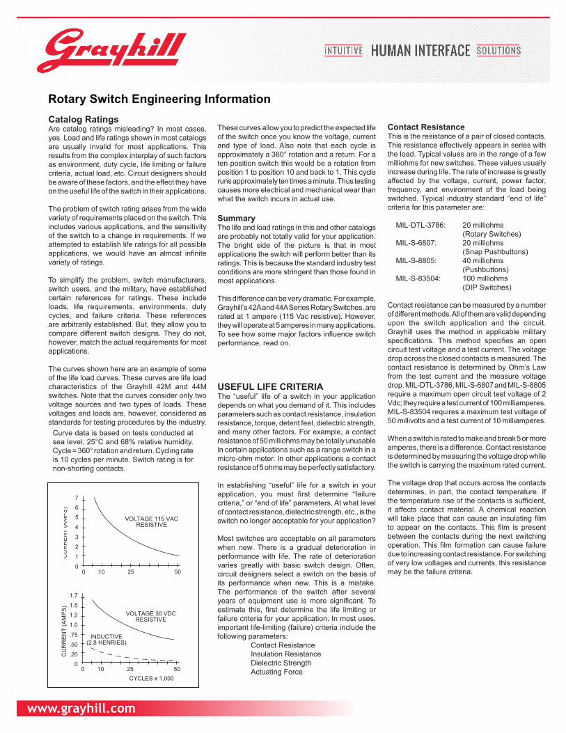
The curves shown here are an example of some of the life load curves. These curves are life load characteristics of the Grayhill 42M and 44M switches. Note that the curves consider only two voltage sources and two types of loads. These voltages and loads are, however, considered as standards for testing procedures by the industry.
Curve data is based on tests conducted at sea level, 25°C and 68% relative humidity. Cycle = 360° rotation and return. Cycling rate is 10 cycles per minute. Switch rating is for non-shorting contacts.
CYCLES x 1,0000 10 25 50
1.7
1.5
1.2
1.0
.75
.50
.20
0
CU
RR
EN
T (A
MP
S)
VOLTAGE 30 VDCRESISTIVE
INDUCTIVE(2.8 HENRIES)
These curves allow you to predict the expected life of the switch once you know the voltage, current and type of load. Also note that each cycle is approximately a 360° rotation and a return. For a ten position switch this would be a rotation from position 1 to position 10 and back to 1. This cycle runs approximately ten times a minute. Thus testing causes more electrical and mechanical wear than what the switch incurs in actual use.
SummaryThe life and load ratings in this and other catalogs are probably not totally valid for your application. The bright side of the picture is that in most applications the switch will perform better than its ratings. This is because the standard industry test conditions are more stringent than those found in most applications.
This difference can be very dramatic. For example, Grayhill’s 42A and 44A Series Rotary Switches, are rated at 1 ampere (115 Vac resistive). However, they will operate at 5 amperes in many applications. To see how some major factors influence switch performance, read on.
USEFUL LIFE CRITERIAThe “useful” life of a switch in your application depends on what you demand of it. This includes parameters such as contact resistance, insulation resistance, torque, detent feel, dielectric strength, and many other factors. For example, a contact resistance of 50 milliohms may be totally unusable in certain applications such as a range switch in a micro-ohm meter. In other applications a contact resistance of 5 ohms may be perfectly satisfactory.
In establishing “useful” life for a switch in your application, you must first determine “failure criteria,” or “end of life” parameters. At what level of contact resistance, dielectric strength, etc., is the switch no longer acceptable for your application?
Most switches are acceptable on all parameters when new. There is a gradual deterioration in performance with life. The rate of deterioration varies greatly with basic switch design. Often, circuit designers select a switch on the basis of its performance when new. This is a mistake. The performance of the switch after several years of equipment use is more significant. To estimate this, first determine the life limiting or failure criteria for your application. In most uses, important life-limiting (failure) criteria include the following parameters: Contact Resistance Insulation Resistance Dielectric Strength Actuating Force
Contact ResistanceThis is the resistance of a pair of closed contacts. This resistance effectively appears in series with the load. Typical values are in the range of a few milliohms for new switches. These values usually increase during life. The rate of increase is greatly affected by the voltage, current, power factor, frequency, and environment of the load being switched. Typical industry standard “end of life” criteria for this parameter are:
MIL-DTL-3786: 20 milliohms (Rotary Switches) MIL-S-6807: 20 milliohms (Snap Pushbuttons) MIL-S-8805: 40 milliohms (Pushbuttons) MIL-S-83504: 100 milliohms (DIP Switches)
Contact resistance can be measured by a number of different methods. All of them are valid depending upon the switch application and the circuit. Grayhill uses the method in applicable military specifications. This method specifies an open circuit test voltage and a test current. The voltage drop across the closed contacts is measured. The contact resistance is determined by Ohm’s Law from the test current and the measure voltage drop. MIL-DTL-3786, MIL-S-6807 and MIL-S-8805 require a maximum open circuit test voltage of 2 Vdc; they require a test current of 100 milliamperes. MIL-S-83504 requires a maximum test voltage of 50 millivolts and a test current of 10 milliamperes. When a switch is rated to make and break 5 or more amperes, there is a difference. Contact resistance is determined by measuring the voltage drop while the switch is carrying the maximum rated current.
The voltage drop that occurs across the contacts determines, in part, the contact temperature. If the temperature rise of the contacts is sufficient, it affects contact material. A chemical reaction will take place that can cause an insulating film to appear on the contacts. This film is present between the contacts during the next switching operation. This film formation can cause failure due to increasing contact resistance. For switching of very low voltages and currents, this resistance may be the failure criteria.
7
6
5
4
3
2
1
00
CYCLES x 1,000
10 25 50
CU
RR
EN
T (A
MP
S)
VOLTAGE 115 VACRESISTIVE
Rotary Switch Engineering Information
www.grayhill.com
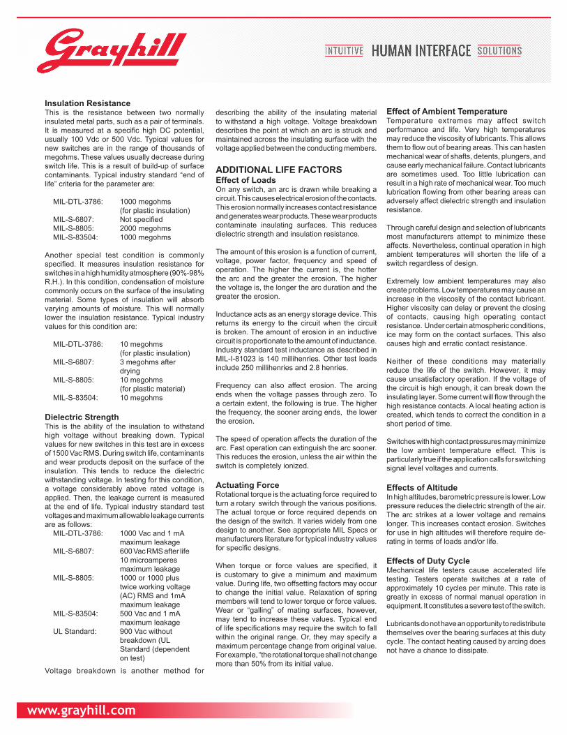
Insulation ResistanceThis is the resistance between two normally insulated metal parts, such as a pair of terminals. It is measured at a specific high DC potential, usually 100 Vdc or 500 Vdc. Typical values for new switches are in the range of thousands of megohms. These values usually decrease during switch life. This is a result of build-up of surface contaminants. Typical industry standard “end of life” criteria for the parameter are:
MIL-DTL-3786: 1000 megohms (for plastic insulation) MIL-S-6807: Not specified MIL-S-8805: 2000 megohms MIL-S-83504: 1000 megohms
Another special test condition is commonly specified. It measures insulation resistance for switches in a high humidity atmosphere (90%-98% R.H.). In this condition, condensation of moisture commonly occurs on the surface of the insulating material. Some types of insulation will absorb varying amounts of moisture. This will normally lower the insulation resistance. Typical industry values for this condition are:
MIL-DTL-3786: 10 megohms (for plastic insulation) MIL-S-6807: 3 megohms after drying MIL-S-8805: 10 megohms (for plastic material) MIL-S-83504: 10 megohms
Dielectric Strength This is the ability of the insulation to withstand high voltage without breaking down. Typical values for new switches in this test are in excess of 1500 Vac RMS. During switch life, contaminants and wear products deposit on the surface of the insulation. This tends to reduce the dielectric withstanding voltage. In testing for this condition, a voltage considerably above rated voltage is applied. Then, the leakage current is measured at the end of life. Typical industry standard test voltages and maximum allowable leakage currents are as follows: MIL-DTL-3786: 1000 Vac and 1 mA maximum leakage MIL-S-6807: 600 Vac RMS after life 10 microamperes maximum leakage MIL-S-8805: 1000 or 1000 plus twice working voltage (AC) RMS and 1mA maximum leakage MIL-S-83504: 500 Vac and 1 mA maximum leakage UL Standard: 900 Vac without breakdown (UL Standard (dependent on test)
Voltage breakdown is another method for
describing the ability of the insulating material to withstand a high voltage. Voltage breakdown describes the point at which an arc is struck and maintained across the insulating surface with the voltage applied between the conducting members.
ADDITIONAL LIFE FACTORSEffect of LoadsOn any switch, an arc is drawn while breaking a circuit. This causes electrical erosion of the contacts. This erosion normally increases contact resistance and generates wear products. These wear products contaminate insulating surfaces. This reduces dielectric strength and insulation resistance.
The amount of this erosion is a function of current, voltage, power factor, frequency and speed of operation. The higher the current is, the hotter the arc and the greater the erosion. The higher the voltage is, the longer the arc duration and the greater the erosion.
Inductance acts as an energy storage device. This returns its energy to the circuit when the circuit is broken. The amount of erosion in an inductive circuit is proportionate to the amount of inductance. Industry standard test inductance as described in MIL-I-81023 is 140 millihenries. Other test loads include 250 millihenries and 2.8 henries.
Frequency can also affect erosion. The arcing ends when the voltage passes through zero. To a certain extent, the following is true. The higher the frequency, the sooner arcing ends, the lower the erosion.
The speed of operation affects the duration of the arc. Fast operation can extinguish the arc sooner. This reduces the erosion, unless the air within the switch is completely ionized.
Actuating ForceRotational torque is the actuating force required to turn a rotary switch through the various positions. The actual torque or force required depends on the design of the switch. It varies widely from one design to another. See appropriate MIL Specs or manufacturers literature for typical industry values for specific designs.
When torque or force values are specified, it is customary to give a minimum and maximum value. During life, two offsetting factors may occur to change the initial value. Relaxation of spring members will tend to lower torque or force values. Wear or “galling” of mating surfaces, however, may tend to increase these values. Typical end of life specifications may require the switch to fall within the original range. Or, they may specify a maximum percentage change from original value. For example, “the rotational torque shall not change more than 50% from its initial value.
Effect of Ambient TemperatureTemperature extremes may affect switch performance and life. Very high temperatures may reduce the viscosity of lubricants. This allows them to flow out of bearing areas. This can hasten mechanical wear of shafts, detents, plungers, and cause early mechanical failure. Contact lubricants are sometimes used. Too little lubrication can result in a high rate of mechanical wear. Too much lubrication flowing from other bearing areas can adversely affect dielectric strength and insulation resistance.
Through careful design and selection of lubricants most manufacturers attempt to minimize these affects. Nevertheless, continual operation in high ambient temperatures will shorten the life of a switch regardless of design.
Extremely low ambient temperatures may also create problems. Low temperatures may cause an increase in the viscosity of the contact lubricant. Higher viscosity can delay or prevent the closing of contacts, causing high operating contact resistance. Under certain atmospheric conditions, ice may form on the contact surfaces. This also causes high and erratic contact resistance.
Neither of these conditions may materially reduce the life of the switch. However, it may cause unsatisfactory operation. If the voltage of the circuit is high enough, it can break down the insulating layer. Some current will flow through the high resistance contacts. A local heating action is created, which tends to correct the condition in a short period of time.
Switches with high contact pressures may minimize the low ambient temperature effect. This is particularly true if the application calls for switching signal level voltages and currents.
Effects of AltitudeIn high altitudes, barometric pressure is lower. Low pressure reduces the dielectric strength of the air. The arc strikes at a lower voltage and remains longer. This increases contact erosion. Switches for use in high altitudes will therefore require de-rating in terms of loads and/or life.
Effects of Duty CycleMechanical life testers cause accelerated life testing. Testers operate switches at a rate of approximately 10 cycles per minute. This rate is greatly in excess of normal manual operation in equipment. It constitutes a severe test of the switch.
Lubricants do not have an opportunity to redistribute themselves over the bearing surfaces at this duty cycle. The contact heating caused by arcing does not have a chance to dissipate.
www.grayhill.com
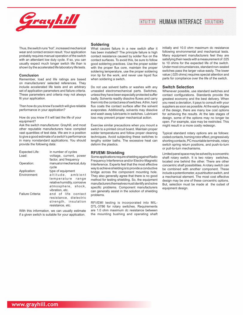
Thus, the switch runs “hot”, increased mechanical wear and contact erosion result. Your application probably requires manual operation of the switch with an attendant low duty cycle. If so, you can usually expect much longer switch life than is shown by the accelerated life laboratory life tests.
ConclusionRemember, load and life ratings are based on manufacturers’ selected references. They include accelerated life tests and an arbitrary set of application parameters and failure criteria. These parameters and criteria may not always fit your application.
Then how do you know if a switch will give reliable performance in your application?
How do you know if it will last the life of yourequipment? Ask the switch manufacturer. Grayhill, and most other reputable manufacturers have compiled vast quantities of test data. We are in a position to give a good estimate of a switch’s performance in many nonstandard applications. You should provide the following data:
Expected Life: in number of cyclesLoad: voltage, current, power
factor, and frequencyOperation: manual or mechanical, duty
cycleApplication: type of equipmentEnvironment: a l t i t u d e , a m b i e n t
t e m p e r a t u r e r a n g e relative humidity, corrosive a tmosphere , shock , vibration, etc.
Failure Criteria: end o f l i fe contac t resistance, dielectr ic s t reng th , i nsu la t i on resistance, etc.
With this information, we can usually estimate if a given switch is suitable for your application.
SolderingWhat causes failure in a new switch after it has been installed? The principle failure is high contact resistance caused by solder flux on the contact surfaces. To avoid this, be sure to follow good soldering practices. Use the proper solder with the proper flux core, maintain the proper soldering temperature, use the proper soldering iron tip for the work, and never use liquid flux when soldering a switch.
Do not use solvent baths or washes with any unsealed electromechanical parts. Switches, unless they have been especially protected suffer badly. Solvents readily dissolve fluxes and carry them into the contact area of switches. A thin, hard flux coats the contact surface after the solvent evaporates. Additionally, solvents may dissolve and wash away lubricants in switches. Lubricant loss may prevent proper mechanical action.
Exercise similar precautions when you mount a switch to a printed circuit board. Maintain proper solder temperatures and follow proper cleaning techniques. Avoid subjecting these switches to lengthy solder baths. The excessive heat can deform the plastics.
RFI/EMI ShieldingSome applications require shielding against Radio Frequency Interference and/or Electro-Magnetic Interference. Experts feel that the most effective way to achieve shielding is to provide a conductive bridge across the component mounting hole. They also generally agree that there is no good method for testing shielding. So, the equipment manufacturers themselves must identify and solve specific problems. Component manufacturers can generally assist in the solution of shielding problems.
RFI/EMI testing is incorporated into MIL-DTL-3786 for rotary switches. Requirements are 1.0 ohm maximum dc resistance between the mounting bushing and operating shaft
initially and 10.0 ohm maximum dc resistance following environmental and mechanical tests. Many equipment manufacturers feel they are satisfying their needs with a measurement of .025 to 10 ohms for the expected life of the switch. Under most circumstances, standard non-sealed switches pass the larger value easily. The lower value (.025 ohms) requires special attention and parts for compliance over the life of the switch.
Switch SelectionWhenever possible, use standard switches and contact configurations. Standards provide the greatest economy and the best delivery. When you need a deviation, it pays to consult with your suppliers as soon as possible. At the early stages of the design, there are many low cost options for achieving the results. At the late stages of design, some of the options may no longer be open. For example, size may be restricted. This might result in a more costly redesign.
Typical standard rotary options are as follows: coded contacts, homing rotor effect, progressively shorting contacts, PC mountable terminals, rotary switch spring return positions, and push-to-turn or pull-to-turn mechanisms.
Limited panel space may be solved by a concentric shaft rotary switch. It is two rotary switches, located one behind the other. There are other concentric shaft possibilities. A rotary switch can be combined with another component. These include a potentiometer, a pushbutton switch, and a mechanical element. The most cost effective design may be one of these concentric options. But, selection must be made at the outset of equipment design.
www.grayhill.com
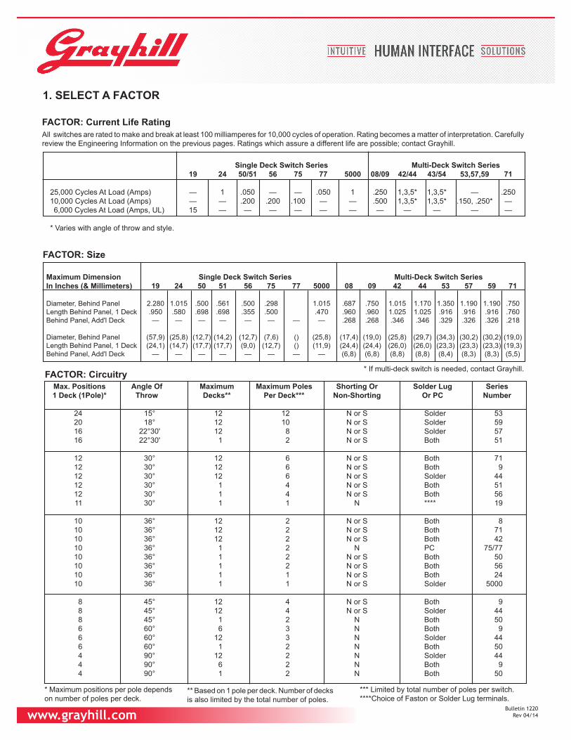
Max. Positions Angle Of Maximum Maximum Poles Shorting Or Solder Lug Series1 Deck (1Pole)* Throw Decks** Per Deck*** Non-Shorting Or PC Number
24 15° 12 12 N or S Solder 5320 18° 12 10 N or S Solder 5916 22°30' 12 8 N or S Solder 5716 22°30' 1 2 N or S Both 51
12 30° 12 6 N or S Both 7112 30° 12 6 N or S Both 912 30° 12 6 N or S Solder 4412 30° 1 4 N or S Both 5112 30° 1 4 N or S Both 56
11 30° 1 1 N **** 19
10 36° 12 2 N or S Both 810 36° 12 2 N or S Both 7110 36° 12 2 N or S Both 42
10 36° 1 2 N PC 75/7710 36° 1 2 N or S Both 5010 36° 1 2 N or S Both 5610 36° 1 1 N or S Both 2410 36° 1 1 N or S Solder 5000
8 45° 12 4 N or S Both 98 45° 12 4 N or S Solder 44
8 45° 1 2 N Both 50 6 60° 6 3 N Both 9 6 60° 12 3 N Solder 44 6 60° 1 2 N Both 50 4 90° 12 2 N Solder 44 4 90° 6 2 N Both 9 4 90° 1 2 N Both 50
** Based on 1 pole per deck. Number of decks is also limited by the total number of poles.
Single Deck Switch Series Multi-Deck Switch Series19 24 50/51 56 75 77 5000 08/09 42/44 43/54 53,57,59 71
25,000 Cycles At Load (Amps) — 1 .050 — — .050 1 .250 1,3,5* 1,3,5* — .25010,000 Cycles At Load (Amps) — — .200 .200 .100 — — .500 1,3,5* 1,3,5* .150, .250* — 6,000 Cycles At Load (Amps, UL) 15 — — — — — — — — — — —
* Varies with angle of throw and style.
Maximum Dimension Single Deck Switch Series Multi-Deck Switch SeriesIn Inches (& Millimeters) 19 24 50 51 56 75 77 5000 08 09 42 44 53 57 59 71
Diameter, Behind Panel 2.280 1.015 .500 .561 .500 .298 1.015 .687 .750 1.015 1.170 1.350 1.190 1.190 .750Length Behind Panel, 1 Deck .950 .580 .698 .698 .355 .500 .470 .960 .960 1.025 1.025 .916 .916 .916 .760Behind Panel, Add'l Deck — — — — — — — — .268 .268 .346 .346 .329 .326 .326 .218
Diameter, Behind Panel (57,9) (25,8) (12,7) (14,2) (12,7) (7,6) () (25,8) (17,4) (19,0) (25,8) (29,7) (34,3) (30,2) (30,2) (19,0)Length Behind Panel, 1 Deck (24,1) (14,7) (17,7) (17,7) (9,0) (12,7) () (11,9) (24,4) (24,4) (26,0) (26,0) (23,3) (23,3) (23,3) (19,3)Behind Panel, Add'l Deck — — — — — — — — (6,8) (6,8) (8,8) (8,8) (8,4) (8,3) (8,3) (5,5)
1. SELECT A FACTOR
All switches are rated to make and break at least 100 milliamperes for 10,000 cycles of operation. Rating becomes a matter of interpretation. Carefully review the Engineering Information on the previous pages. Ratings which assure a different life are possible; contact Grayhill.
FACTOR: Current Life Rating
FACTOR: Size
* If multi-deck switch is needed, contact Grayhill.FACTOR: Circuitry
* Maximum positions per pole dependson number of poles per deck.
*** Limited by total number of poles per switch.****Choice of Faston or Solder Lug terminals.
Bulletin 1220 Rev 04/14
www.grayhill.com Patent Pending ©2013
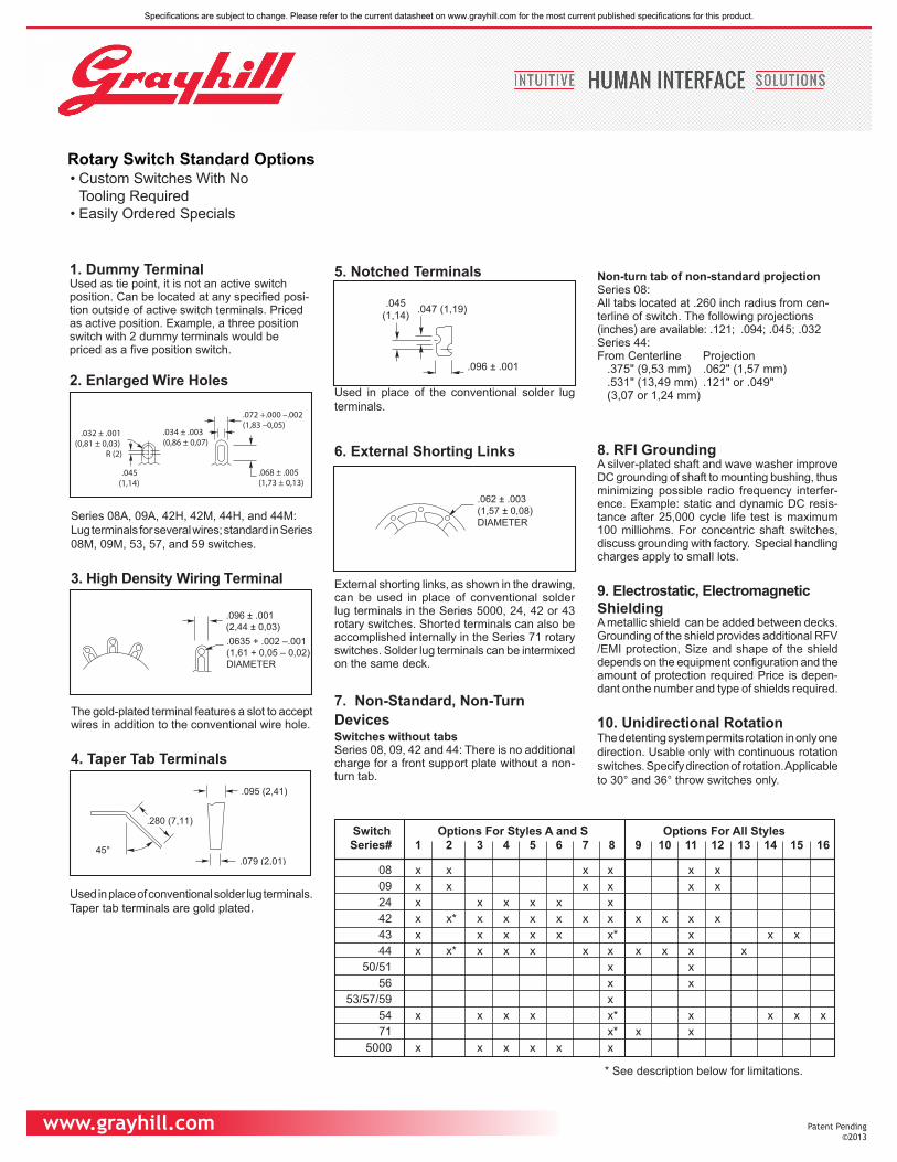
• Custom Switches With NoTooling Required
• Easily Ordered Specials
1. Dummy TerminalUsed as tie point, it is not an active switch position. Can be located at any specified posi-tion outside of active switch terminals. Priced as active position. Example, a three position switch with 2 dummy terminals would be priced as a five position switch.
2. Enlarged Wire Holes
Series 08A, 09A, 42H, 42M, 44H, and 44M:Lug terminals for several wires; standard in Series 08M, 09M, 53, 57, and 59 switches.
3. High Density Wiring Terminal
The gold-plated terminal features a slot to accept wires in addition to the conventional wire hole.
4. Taper Tab Terminals
Used in place of conventional solder lug terminals. Taper tab terminals are gold plated.
5. Notched Terminals
Used in place of the conventional solder lug terminals.
6. External Shorting Links
External shorting links, as shown in the drawing, can be used in place of conventional solder lug terminals in the Series 5000, 24, 42 or 43 rotary switches. Shorted terminals can also be accomplished internally in the Series 71 rotary switches. Solder lug terminals can be intermixed on the same deck.
7. Non-Standard, Non-TurnDevicesSwitches without tabsSeries 08, 09, 42 and 44: There is no additional charge for a front support plate without a non-turn tab.
Non-turn tab of non-standard projectionSeries 08:All tabs located at .260 inch radius from cen-terline of switch. The following projections (inches) are available: .121; .094; .045; .032Series 44:From Centerline Projection
.375" (9,53 mm) .062" (1,57 mm)
.531" (13,49 mm) .121" or .049"(3,07 or 1,24 mm)
8. RFI GroundingA silver-plated shaft and wave washer improve DC grounding of shaft to mounting bushing, thus minimizing possible radio frequency interfer-ence. Example: static and dynamic DC resis-tance after 25,000 cycle life test is maximum 100 milliohms. For concentric shaft switches, discuss grounding with factory. Special handling charges apply to small lots.
9. Electrostatic, ElectromagneticShieldingA metallic shield can be added between decks. Grounding of the shield provides additional RFV /EMI protection, Size and shape of the shield depends on the equipment configuration and the amount of protection required Price is depen-dant onthe number and type of shields required.
10. Unidirectional RotationThe detenting system permits rotation in only one direction. Usable only with continuous rotation switches. Specify direction of rotation. Applicable to 30° and 36° throw switches only.
.032 ± .001(0,81 ± 0,03)
R (2)
.045(1,14)
.034 ± .003(0,86 ± 0,07)
.072 +.000 –.002(1,83 –0,05)
.068 ± .005(1,73 ± 0,13)
.096 ± .001(2,44 ± 0,03).0635 + .002 –.001(1,61 + 0,05 – 0,02)DIAMETER
.095 (2,41)
.079 (2,01)
.280 (7,11)
45°
.045(1,14) .047 (1,19)
.096 ± .001(2,44 ± 0,03)
.062 ± .003(1,57 ± 0,08)DIAMETER
Rotary Switch Standard Options
Switch Options For Styles A and S Options For All StylesSeries# 1 2 3 4 5 6 7 8 9 10 11 12 13 14 15 16
08 x x x x x x 09 x x x x x x 24 x x x x x x 42 x x* x x x x x x x x x x 43 x x x x x x* x x x 44 x x* x x x x x x x x x
50/51 x x 56 x x
53/57/59 x 54 x x x x x* x x x x71 x* x x
5000 x x x x x x
* See description below for limitations.
Specifications are subject to change. Please refer to the current datasheet on www.grayhill.com for the most current published specifications for this product.
www.grayhill.com
11. Intermixing of Shorting and Non-Shorting ContactsIn some switches, non-shorting and shorting contacts can be intermixed between decks. A 2-deck switch, for example could have shorting contacts on deck 1 and non-shorting contactson deck 2. In a few switches, non-shortingand shorting contacts can also be intermixedbetween poles. A 2-pole per deck switch, forexample, could have non-shorting on pole #1,and shorting on pole #2.
Series 08 and 09:An 09M30 or 08M36 rotary switch can have shorting and non-shorting contacts intermixed between decks. Shorting and non-shorting contacts can be intermixed between poles as well as decks in styles A, S, P, and SP.
Series 42, 43, 44, and 54, in 30° or 36°:Non-shorting and shorting contacts can be intermixed between poles or decks.
Series 50, 51, and 56:Non-shorting and shorting contacts can be intermixed between poles.
Series 71:Non-shorting and shorting contacts can be intermixed between poles in fixed stop switches only.
Priced the same as standard switches. The type of contacts on each pole must be precisely indicated.
12. PC Mount Switches WithTerminals From One Sideof SwitchSeries 71 PC mount switch has all terminals on one side.
Series 08P, 09P, and 42P with non-shorting contacts are also available with terminals limited to one side. Contact Grayhill for a special part number. This is accomplished by using 2 decks per pole and placing the rotating contacts 180° out of phase on each deck. The first deck picks up the first half of the positions; the second deck picks up the last half of the positions. Common terminals are tied together by the PC board circuitry.
A total of 12 decks (6 usable poles) is the maximum per switch. Switches with the maximum number of positions (12 for 30°, or 10 for 36°) will have continuous rotation. Rotation can be limited to less than the maximum positions. For example, an 8 position Series 8P36 switch with terminals on one side, would pick up 5 positions on the first deck and 3 positions on the second deck.
Price is the same as standard switches with comparable number of decks and positions.
Example: an 08P36, 1-pole, 10 position switch with terminals on one side of the switch would be priced as a 2 deck, five position, one pole per deck switch.
13. Homing Rotor (Bridging andShorting Deck) and ProgressivelyShorting Deck - Series 44 onlyA homing rotor (bridging and shorting) switch deck connects all terminals to the common except the terminal in the selected switch position. For example, in position 1, terminals 2 thru 12 are
CIRCUITDIAGRAM
HOMINGROTOR DECK1
2
3
4
5
678
9
10
11
12C
connected to the common, and terminal 1 is open. In position 2, terminal 3 thru 12 and 1 are connected to the common, and terminal 2 is open. A homing rotor deck will function for 25,000 mechanical cycles of operation.The progressively shorting switch deck connects consecutive switch positions to the common. For example, in position 1, terminal 1 is connected to the common; in position 2, terminals 1 and 2 are connected to the common; in position
CIRCUITDIAGRAM
PROGRESSIVELYSHORTING DECK
12
3
4
5
6
C
3, terminals 1,2, and 3 are connected to the common. A progressively shorting deck is limited to a maximum of 6 positions. A progressively shorting deck will function for 25,000 mechanical cycles of operation.
Homing Rotor or Progressively Shorting decks can be ordered as a deck of a 44A or 44M style switch, or their sealed equivalents. Order up to 11 conventional decks and 1 special circuitry deck. For a good detent feel, the switch is limited to a total of 12 poles plus the homing rotor or progressively shorting deck. Example: 6 2-pole decks and a homing rotor. When these special
decks are used in combination with conventional decks, it is important to remember that the stop system limits the rotation of both types of decks. For example, when a homing rotor deck Is used in combination with a 6-position conventional deck, the homing rotor is likewise limited to six positions.
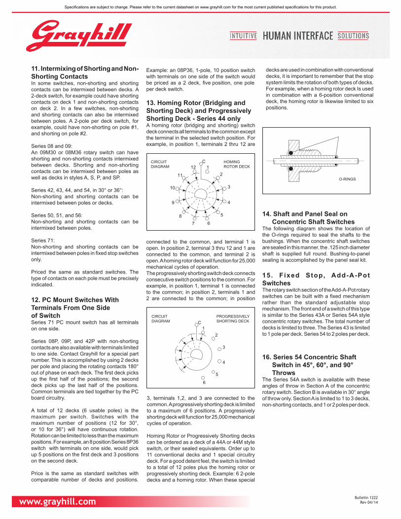
O-RINGS
14. Shaft and Panel Seal onConcentric Shaft Switches
The following diagram shows the location of the O-rings required to seal the shafts to the bushings. When the concentric shaft switches are sealed in this manner, the .125 inch diameter shaft is supplied full round. Bushing-to-panel sealing is accomplished by the panel seal kit.
15. Fixed Stop, Add-A-PotSwitchesThe rotary switch section of the Add-A-Pot rotary switches can be built with a fixed mechanism rather than the standard adjustable stop mechanism. The front end of a switch of this type is similar to the Series 43A or Series 54A style concentric rotary switches. The total number of decks is limited to three. The Series 43 is limited to 1 pole per deck. Series 54 to 2 poles per deck.
16. Series 54 Concentric ShaftSwitch in 45°, 60°, and 90°Throws
The Series 54A switch is available with these angles of throw in Section A of the concentric rotary switch. Section B is available in 30° angle of throw only. Section A is limited to 1 to 3 decks, non-shorting contacts, and 1 or 2 poles per deck.
Bulletin 1222 Rev 04/14
Specifications are subject to change. Please refer to the current datasheet on www.grayhill.com for the most current published specifications for this product.

Mouser Electronics
Authorized Distributor
Click to View Pricing, Inventory, Delivery & Lifecycle Information: Grayhill:
05003-02N 05003-05N 05004-03N 05004-02N 05002-07N 05003-03N 05003-04N 05002-02N 05003-10N
05002-03N 05002-10N
Related Documents