Edition May 2000 ANSI Version Technical Information T 8000-1 Associated Technical Data Sheets T 8012 to T 8097 T 8250 to T 8265 Survey of Valve Materials T 8000-2 Series 3240 ⋅ 3250 ⋅ 3280 ⋅ 3510 ⋅ 3520 ⋅ PFEIFFER Series 1 Control Valves for Industrial Processes Technical Information • Selection Guide Size ½” ... 16” • Class 125 ... 2500 • –420 ... +1100 °F Globe • Angle • 3-Way • Diaphragm • Sanitary • Micro • Steam Conditioning

Welcome message from author
This document is posted to help you gain knowledge. Please leave a comment to let me know what you think about it! Share it to your friends and learn new things together.
Transcript

Edition May 2000 ANSI Version
Technical Information T 8000-1
Associated Technical Data Sheets T 8012 to T 8097T 8250 to T 8265
Survey of Valve Materials T 8000-2
Series 3240 ⋅ 3250 ⋅ 3280 ⋅ 3510 ⋅ 3520 ⋅ PFEIFFER Series 1
Control Valves for Industrial Processes
Technical Information • Selection Guide
Size ½” ... 16” • Class 125 ... 2500 • –420 ... +1100 °F
Globe • Angle • 3-Way • Diaphragm • Sanitary • Micro • Steam Conditioning

2 T 8000-1
ContentsSAMSON Control Valves
Series 3240, Valves for Special Applications, Series 3500,PFEIFFER Series 1, Series 3250, and 3280 3
Table 1a ⋅ Control Valves - up to Class 300 andValves for Special Applications 4
Table 1b ⋅ Control Valves - up to Class 2500 5Table 1c ⋅ Steam-converting Valves - Series 3280 5
Series 3240Globe Valve Type 3241 6Forged Steel Version Type 3241 6Three-way Valve Type 3244 6
Valves for Special ApplicationsCryogenic Valve Type 3248 7Control Valve for Aseptic Operation Type 3249 7Diaphragm Control Valve Type 3345 7Control Valve for Food Processing Type 3347 7Pneumatic ON/OFF Valve Type 3351 8
Series 3500Micro-flow Control Valve Type 3510 8Globe Valve Type 3521 8Globe Valve Type 3522 8
Series 1PFEIFFER Globe Valve Type 1a 9PFEIFFER Globe Valve Type 1b 9PFEIFFER Globe Valve Type 1c 9PFEIFFER Globe Valve Type 1d 9
Series 3250Globe Valve Type 3251 10Globe Valve Type 3252 10Three-way Valve Type 3253 10Globe Valve Type 3254 10Globe Valve with Axial MultistageThrottling Plug Type 3255 11Angle Valve Type 3256 11Angle Valve with Split-body Type 3258 11
Series 3280Steam-converting Valves Type 3281 and Type 3286 11Steam-converting Valve Type 3284 11
ActuatorsPneumatic Actuators 12Electric Actuators 12Electro-hydraulic Actuators 12Hand-operated Actuators 12
Accessories for Control ValvesPositioner 13Limit Switch 13Position Transmitter / Potentiometer 13Solenoid Valve 13Lockup Valve 13Pneumatic Remote Adjuster 13Supply Pressure Regulator 13Air Pressure Reducing Station 13Pneumatic Amplifier 13
Control Valves in Detail
Valve body and styles 14Globe Valve 14Three-way Valve 14Angle Valve 14Split-body Valve 15Cryogenic Valve 15Control Valve for Food Processing 15Diaphragm Control Valve 15ON/OFF Valve 16Lined Valves 16Micro-flow Control Valve 16Steam-converting Valve 16
Valve bonnetPacking 17Steam connection 17
The Trim Elements: Seat and Plug 18Seat Leakage 18Low-noise Operation with Flow Divider 18Pressure-balanced Plug 18Control Valves with Ceramic Trim Elements 19
Additional Equipment 19Metal Bellows Seal 19Insulating Section 19Heating Jacket 19
Piping Connections 20
Face-to-face and End-to-end Dimensions 20Tables 3a...6a ⋅ ”L” and “L1” dimensions ⋅ inches 21Tables 3b...6b ⋅ ”L” and “L1” dimensions ⋅ mm 22
Valve-specific ParametersFlow coefficients 23Inherent Characteristic 23Rangeability 23Cavitation Parameters 23Table 7 ⋅ Nominal Cv verses relative travel 24Table 8 ⋅ FL, xT, and Kc verses relative travel 24
Valve SizingCalculation of the Cv value 25Valve Selection 25
Calculation of the Sound EmissionTable 10 ⋅ z value ⋅ Series 3240 and 3250 26Gases and Vapors 27Liquids 27
MaterialsTable 11 ⋅ Materials according to ASTM and DIN 28
Pressure ratingsTable 12 ⋅ According to ASME/ANSI 29
Valve Materials and Pressure RatingsTable 13 ⋅ Series 3240, 3250 and 3280 30
Selection and Ordering InformationSelection and Sizing of the Control Valve 31Ordering Information 31
Data Sheet for Control Valves ⋅ According to ISA-S20.50 32
SAMSON Control ValvesThe SAMSON Control Valves Series 3240, 3250 and 3280 com-prise pneumatic and electric globe valves, three-way valves andangle valves. Their application range extends from control tasks inprocess and industrial plants to the use in plant engineering andsupply and distribution systems. The modular system allows easyretrofitting and servicing.The control valves consist of the valve and the actuator. They canbe equipped with pneumatic, electric, electro-hydraulic or hand-operated actuators. For controlling purposes and travel indica-tion, accessories such as positioners, limit switches and solenoidvalves can either be attached directly (see page 19 and Informa-tion Sheet T 8350) or according to EN 60 534-6 (NAMUR rib).The valve bodies are made of cast iron, spheroidal graphite iron,cast carbon steel , stainless or cold-resisting cast steel, forged car-bon steel or forged stainless steel as well as other special materi-als. With the completely corrosion-resistant version, all the partsof the valve and the body of the pneumatic actuator are made ofstainless steel. Please refer to the associated Technical Data Sheetsfor details.
Valves up to ANSI Class 300 / PN 50Series 3240Control Valves Series 3240 are available in ANSI nominal valvesizes ½” to 10” and in metric nominal sizes from DN 15 to DN250. Pressure ratings up to ANSI Class 300 and nominal pressurePN 40. Control valves in the standard version are suitable for tem-peratures of 15 to 430 °F (−10 to +220 °C). In addition, the appli-cation range can be extended by means of an insulating section tothe temperature range −325 to +840 °F (−200 to +450 °C). Theplug stem is sealed either by a self-adjustable PTFE V-ring packingor an adjustable packing. If the external tightness of the seal issubject to particular stress, a stainless steel bellows is used. TheType 3241 Control Valves can be equipped with a heating jacketthat may also cover the bellows.
Valves for Special ApplicationsThese valves have been developed for special requirements, someof which are up to ANSI Class 300, and others up to Class 2500.They essentially include cryogenic valves, valves for food process-ing, diaphragm control valves and micro-flow control valves.
Series 3500The Type 3510 Micro-flow Control Valve is designed for precisethrottling of small flow rates, with flow coefficients as low as the or-der of 10-5. They are available in nominal sizes from ¼” to ½”and DN 10 to 15, for of ANSI Classes 150 to 1500 and nominalpressures PN 40 and PN 400 and for temperatures up to 1020 °F(550 °C).
The Series 3520 control valves are based on the Type 3241 de-sign, but come standard with female threaded end connectionsand a threaded bonnet. They utilize the same packing design andthe majority of the same trim parts from the Type 3241. They areavailable in bronze and stainless steel in nominal sizes ½” to 2”and a suitable for temperatures from −20 to +430 °F (−29 to+220 °C).
PFEIFFER Series 1For highly corrosive process media, valves with all wetted parts ofPTFE or PFA are the most efficient solution. PFEIFFER, a member ofthe SAMSON Group, specializes in lined control valves and pro-duces the Series 1. The Series 1 are globe control valves with PTFEtrim and bellows. The Type 1a, available in nominal valve sizes1” to 6” and DN 25 to 150, with flanged ends according to ANSIClass 150 and PN 10/16, has a heavy duty PTFE liner for thetoughest applications. The Type 1b, in sizes 1” to 3” and DN 25to 80, has a more economical PFA liner, but is impervious to mostliquid acidic media such as HCl and H2SO4. Both valves featureeasily exchangeable PTFE trim, and are applicable from −20 to+390 °F (−29 to +200 °C).
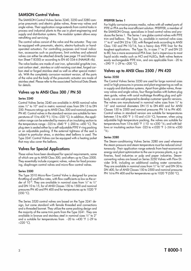
Valves up to ANSI Class 2500 / PN 420Series 3250The Control Valves Series 3250 are used for large nominal sizesand/or high pressures in process and plant engineering as well asin supply and distribution systems. Apart from globe valves, three-way valves and angle valves, four-flange bodies with bottom plugstem guide, valves with axial multistage throttling plug and split-body, we are well prepared to develop customer-specific versions.The valves are manufactured in nominal valve sizes from ½” to16” and nominal diameters DN 15 to DN 400 and for ANSIClasses 150 to 2500 and nominal pressures PN 16 to PN 400.Control valves in standard version are suitable for temperaturesbetween 15 to 430 °F (−10 and +220 °C), however, when usingadjustable high-temperature packing, the valves are suitable fortemperatures from 15 to 660 °F (-10 τo +350 °Χ), and with bel-lows or insulating section from -325 to +1020 °F (−200 to +550°Χ).
Series 3280The Steam-conditioning Valves Series 3280 are used wheneverthe steam pressure and steam temperature must be reduced simul-taneously. Their application range extends from heat-economicalenergy and plant optimization to the use in process plants, e.g. re-fineries, food industries or pulp and paper industries. Steam-converting valves are based on Series 3250 Valves with Flow Di-vider St III, including an additional cooling water connection.They are available in nominal sizes from ½” to 16” and DN 50 toDN 400, for of ANSI Classes 150 to 2500 and nominal pressuresPN 16 to PN 400 and for temperatures up to 1020 °F (550 °C).
3 T 8000-1

T 8000-14
Table 1a • Control Valves - up to ANSI Class 300 / PN 50 and Valves for Special Applications
Control valve Series 3240 For Special Applications Series 1
Type3241
3244 3248 3249 3345 3347 3351 3520 1a 1b-ANSI -DIN
Technical Data Sheet T ... 8012 8015 8026 8093 8048 8031 8097 8039 8020 111a 111b
Globe valve • • • • • • • •
Three-way mixing or diverting valve •
Angle valve • • •
Standard versionANSI • • • • • • • • •
DIN • • • • • • • • •
JIS • •
Specialapplica-tions
Low flow rates
Lined valves • • •
ON/OFF valve •
Pharmaceutical/food industry • • •
Cryogenic technology •
Nominal valve sizes[inch] ½…10 ½…6 ½…6 ½…2 ½…4 ½…4 ½...2 1...6 1...3
[mm] 15...250 15...150 15...150 15...50 15...100 25...100 15...100 25...150 25...80
Nominal pressureClass 125, 300 150, 300 150, 300 125 150, 300 300 150 150
PN 10... 40 16…40 16... 40 10 10 16 16…40 10/16 10/16
JIS 10/20
Perm. temperatures and differential pressures See associated Technical Data Sheet
Bodymaterial
ASTM A 126 B, cast iron • •
ASTM A 216 WCB, cast carbon steel • •
ASTM A 351 CF8M, cast stainl. steel • • • • • CF3M
Cast iron GG-25, WN 0.6025 • • • •
Spheroidal graphite (ductile nodulariron, WN 0.7043, ASTM A 395 • • • •
Cast steel GS-C25, WN 1.0619 • • •
Cast stainless steel, WN 1.4581 • • • 1.4404 •
Forged steel WN 1.0460 •
Forged stainless steel WN 1.4571 • • •
G-X 6 Cr Ni 189 WN 1.4308 •
GS 21 Mn5, WN 1.1138 •
Special material • • • • • • B148-9A
Plug
Metal sealed • • • • • • • •
Lapped-in metal sealed • • • •
Soft sealed • • • • • • •
Pressure-balanced • • • •
Diaphragm seal • •
Option
Insulating section • • • •
Metal bellows seal • • • • • •
Heating jacket • • •
Low-noise (flow divider) • •
Flange • • • • • • • •
Connection Welding ends • • • • • •
Special connections • • • • • NPT-F
Technical Data Sheet T ... 8012 8015 8026 8093 8048 8031 8097 8039 8020 111a 111b
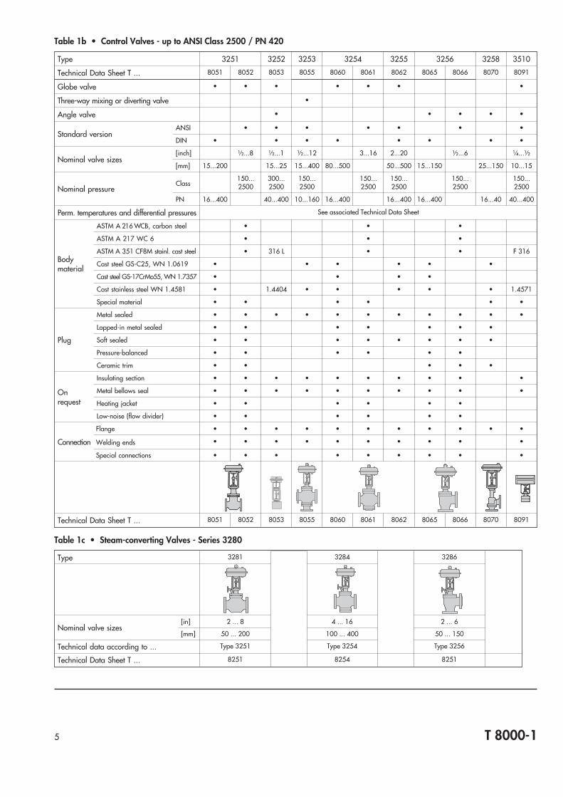
Table 1b • Control Valves - up to ANSI Class 2500 / PN 420
Type 3251 3252 3253 3254 3255 3256 3258 3510
Technical Data Sheet T ... 8051 8052 8053 8055 8060 8061 8062 8065 8066 8070 8091
Globe valve • • • • • • •
Three-way mixing or diverting valve •
Angle valve • • • • •
Standard versionANSI • • • • • • •
DIN • • • • • • • •
Nominal valve sizes[inch] ½...8 ½...1 ½...12 3...16 2...20 ½...6 ¼...½
[mm] 15...200 15...25 15...400 80...500 50...500 15...150 25...150 10...15
Nominal pressureClass
150...2500
300...2500
150...2500
150...2500
150...2500
150...2500
150...2500
PN 16...400 40...400 10...160 16...400 16...400 16...400 16...40 40...400
Perm. temperatures and differential pressures See associated Technical Data Sheet
Bodymaterial
ASTM A 216 WCB, carbon steel • • •
ASTM A 217 WC 6 • • •
ASTM A 351 CF8M stainl. cast steel • 316 L • • F 316
Cast steel GS-C25, WN 1.0619 • • • • • •
Cast steel GS-17CrMo55, WN 1.7357 • • • •
Cast stainless steel WN 1.4581 • 1.4404 • • • • • 1.4571
Special material • • • • • •
Plug
Metal sealed • • • • • • • • • • •
Lapped-in metal sealed • • • • • • •
Soft sealed • • • • • • • •
Pressure-balanced • • • • • •
Ceramic trim • • • • •
Onrequest
Insulating section • • • • • • • • • •
Metal bellows seal • • • • • • • • • •
Heating jacket • • • • • •
Low-noise (flow divider) • • • • • •
Flange • • • • • • • • • • •
Connection Welding ends • • • • • • • • • •
Special connections • • • • • • • • •
Technical Data Sheet T ... 8051 8052 8053 8055 8060 8061 8062 8065 8066 8070 8091
Table 1c • Steam-converting Valves - Series 3280
Type 3281 3284 3286
Nominal valve sizes[in] 2 ... 8 4 ... 16 2 ... 6
[mm] 50 ... 200 100 ... 400 50 ... 150
Technical data according to ... Type 3251 Type 3254 Type 3256
Technical Data Sheet T ... 8251 8254 8251
5 T 8000-1
Series 3240Type 3241 Globe Control Valve (T 8012 to T 8022)This valve is used for various applications in process and industrialplants as well as in plant engineering and supply and distributionsystems. Versions according to DIN, ANSI and JIS are manufac-tured on industrial scale.Valve bodies made of cast iron, spheroidal graphite iron, castcarbon steel, stainless or cold-resistant cast steel.
Nominal valve size ½” ... 10” DN 15 ... 250
Nominal pressure ANSI Class 125...300JIS 10/20 K
PN 10 ... 40
Temperature range −325 ... +840 °F −200 ... +450 °C
Valve plug with metal sealing, soft sealing, or lapped-in metalplug.Further versions including adjustable packing, metal bellows seal,insulating section, heating jacket and flow divider for reducing thesound emission are available.
Type 3241 Forged-steel Version (T 8012 and T 8015)Valve body and valve bonnet made of carbon steel ASTM A 105or C22.8 or stainless steel A 182 F316 or WN 1.4571.
Nominal valve size ½” ... 3” DN 15 ... 80
Nominal pressure ANSI Class 300 PN 16 ... 40
Temperature range −325 ... +840 °F −200 ... +450 °C
Further details and versions are the same as for the cast body ofType 3241 (see above).
Type 3244 Three-way Control Valve (T 8026)Control valve for mixing and diverting service according to DIN orANSI standards. The arrangement of the plugs which is fixed by themanufacturer settles either mixing or diverting service (see valvebody on p. 11).Valve body made of cast iron, cast steel or stainless cast steel (ac-cording to DIN or ASTM specifications).
Nominal valve size ½” ... 6” DN 15 ... 150
Nominal pressure ANSI Class 150 ... 300 PN 10 ... 40
Temperature range −325 ... +840 °F −200 ... +450 °C
Valve plug with metal seal. Further versions with insulating sec-tion, adjustable packing, metal bellows seal, heating jacket andadditional handwheel available.
6 T 8000-1
Type 3241-1
Type 3241-7, forged steel
Type 3244-7

Valves for Special ApplicationsType 3248 Cryogenic Valve (T8093)Control valve used for liquid gases in the field of cryogenic engi-neering. Installation in vacuum-insulated pipelines.
Nominal valve size ½” ... 6” DN 15 ... 150
Nominal pressure ANSI Class 150 ... 300 PN 16 ... 40
Temperature range −325 ... +430 °F −200 ... +220 °C
Valve plug with soft seal. Metal bellows seal with backup stuffingbox. Special version with aluminum body.
Type 3249 Control Valve for Aseptic Service (T8048)Angle valve for food and pharmaceutical industry according toDIN or ANSI standards. PTFE-coated EPDM diaphragm serves asexternal sealing; additional test connection and backup stuffingbox.
Nominal valve size ½” ... 2” DN 15 ... 50
Nominal pressure ANSI Class 125 PN 10 ... 40
Temperature range 14 ... 284 °F −10 ... +140 °C
Versions with threaded coupling, conical coupling and slottedround nut or flanges, and according to ANSI with flanges orclamp weld-on coupling are available.
Type 3345 Diaphragm Control Valve (T 8031)Control valve for viscous, corrosive and abrasive fluids accordingto ANSI or DIN standards.Valve body made of cast iron, spheroidal graphite iron or stain-less cast steel with or without lining.Valve diaphragm made of bu-
Nominal valve size ½” ... 4” DN 15 ... 100
Nominal pressure ANSI Class 125 PN 10
Temperature range 15 ... 300 °F −10 ... +150 °C
Versions for higher temperatures available on request.
Type 3347 Control Valve for Food Processing (T 8097)Angle valve for food and pharmaceutical industry as well as forbiochemistry equipped with weld-on, screw or clamp connections.
Nominal valve size ½” ... 4” DN 25 ... 100
Nominal pressure ANSI Class 150 PN 16
Temperature range 15 ... 300 °F −10 ... +150 °C
7 T 8000-1
Type 3249-7
Type 3347-7
Type 3345-1Type 3248-7
tyl, FKM or ethylene propylene (also with PTFE protective facing).

Valves for Special Applications
Type 3351 Pneumatic ON/OFF Control Valve (T 8039)On/Off valve with tight closure for liquids, nonflammable gasesand steam.Valve body made of cast iron, cast steel or stainless cast steel.
Nominal valve size ½” ... 4” DN 15 ... 100
Nominal pressure ANSI Class 125 ... 300 PN 16 ... 40
Temperature range 15 ... 430 °F −10 ... +220 °C
Valve plug with metal seal as well as with soft seal.Self-adjusting PTFE V-ring packing.Further versions with additional handwheel available.
Series 3500Type 3510 Micro-flow Control Valve (T8091)Stainless steel control valve for low flow rates designed as globevalve or angle valve.
Nominal valve size 14”, 3
8”, 12” NPT-F
12” flanged
14”, 3
8”, 12”,
DN 10 and 15 flanged
Nominal pressure ANSI Class 150, 300,600 and 1500
PN 40 and 400
Temperature range −360 ... 1022 °F −220 ... +550 °C
Versions with insulating section or metal bellows seal available.
Type 3521 Globe Control Valve (T8020)Bronze and stainless steel control valve with NPT female threadedend connections. Compact design with integrated actuator di-rectly mounted to the valve bonnet.
Nominal valve size ½”…2” NPT-F
Nominal pressure ANSI Class 300
Temperature range −20 ... 430 °F −10 ... +220 °C
Valve plug with metal sealing, soft sealing, or lapped-in metalplug.Further versions including adjustable packing available.
Type 3522 Globe Control Valve (T8020)Bronze and stainless steel control valve with NPT female threadedend connections.
Nominal valve size ½”…2” NPT-F
Nominal pressure ANSI Class 300
Temperature range −20 ... 430 °F −10 ... +220 °C
Valve plug with metal sealing, soft sealing, or lapped-in metalplug.Further versions including adjustable packing available.
8 T 8000-1
Type 3522-1
Type 3521-7Type 3351-1
Type 3510-7

PFEIFFER Series 1Type 1a PTFE-Lined Globe Control Valve (T 111a)This valve is used for especially corrosive applications in processand industrial plants as well as in plant engineering and supplyand distribution systems. Versions according to DIN and ANSI aremanufactured.Valve bodies made of ductile (spheroidal graphite) iron, withheavy-duty isostatically formed PTFE liner. A PTFE bellows seal isstandard, optionally of material TFM.
Nominal valve size 1” ... 6” DN 25 ... 150
Nominal pressure See diagram
Flanges ANSI Class 150 PN 16
Temperature range −20 ... +390 °F −29 ... +200 °C
Further versions including slotted anti-cavitation plug, and anti-static conductive liner are available.
Type 1d PTFE-Lined 3-Way Globe Control Valve (on request)This valve is essentially the same design as the Type 1a, but with asecond plug and seat for the third port through the bottom flange.
Nominal valve size 1” ... 6” DN 25 ... 150
Nominal pressure See diagram
Flanges ANSI Class 150 PN 16
Temperature range −20 ... +390 °F −29 ... +200 °C
Further versions as for the Type 1a are available.
Type 1b PFA-Lined Globe Control Valve (T 111b)This valve is used for similar applications to the Type 1a. Versionsaccording to DIN and ANSI are manufactured.Valve bodies made of ductile (spheroidal graphite) iron, withtransfer-moulded PFA liner. A PTFE bellows seal is standard, op-tionally of material TFM.
Nominal valve size 1” ... 3” DN 25 ... 80
Nominal pressure See diagram
Flanges ANSI Class 150 PN 16
Temperature range −20 ... +390 °F −29 ... +200 °C
Further versions including slotted anti-cavitation plug areavailable.
Type 1c PFA-Lined Globe Control Valve (on request)The Type 1c is essentially the same as the 1b, but with adiaphragm-type stem seal, in lieu of a bellows.
Nominal valve size 1” ... 3” DN 25 ... 80
Nominal pressure See diagram
Flanges ANSI Class 150 PN 16
Temperature range −20 ... +390 °F −29 ... +200 °C
Further versions as for the Type 1b are available.
9 T 8000-1
Type 1a
Type 1b(with PTFE bellowsseal)
Type 1c(with diaphragmstem seal)
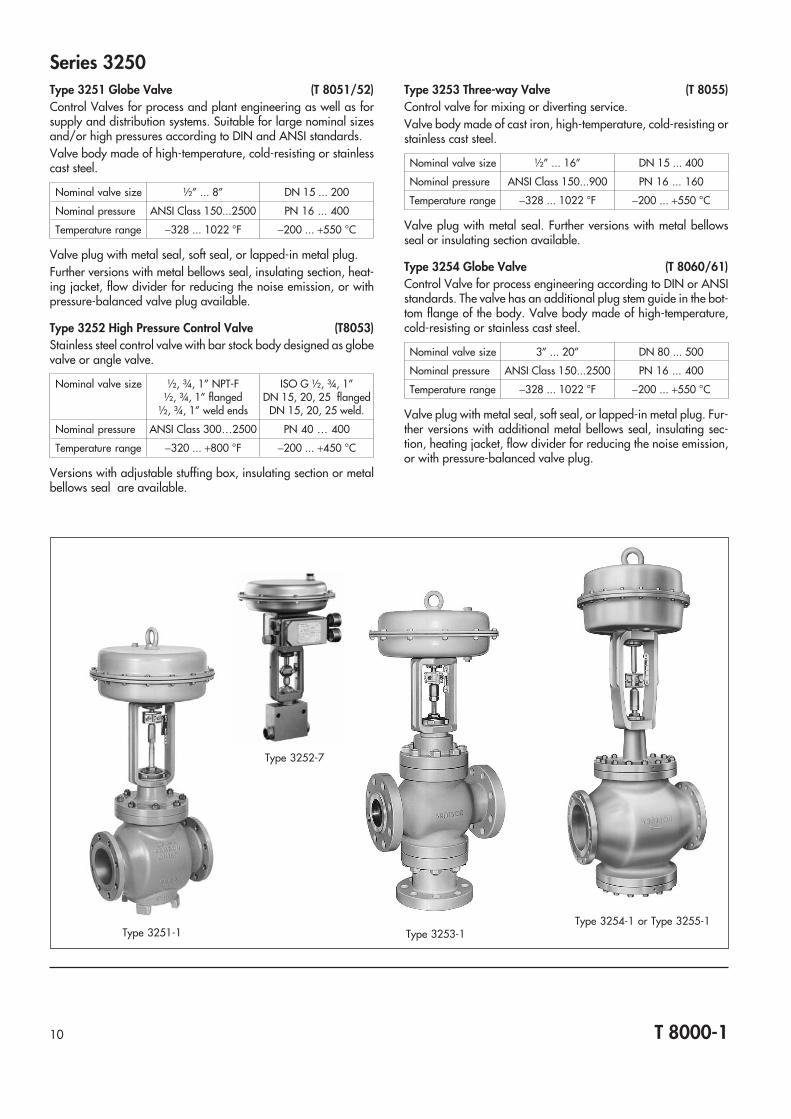
Series 3250Type 3251 Globe Valve (T 8051/52)Control Valves for process and plant engineering as well as forsupply and distribution systems. Suitable for large nominal sizesand/or high pressures according to DIN and ANSI standards.Valve body made of high-temperature, cold-resisting or stainlesscast steel.
Nominal valve size ½” ... 8” DN 15 ... 200
Nominal pressure ANSI Class 150...2500 PN 16 ... 400
Temperature range −328 ... 1022 °F −200 ... +550 °C
Valve plug with metal seal, soft seal, or lapped-in metal plug.Further versions with metal bellows seal, insulating section, heat-ing jacket, flow divider for reducing the noise emission, or withpressure-balanced valve plug available.
Type 3252 High Pressure Control Valve (T8053)Stainless steel control valve with bar stock body designed as globevalve or angle valve.
Nominal valve size ½, ¾, 1” NPT-F½, ¾, 1” flanged
½, ¾, 1” weld ends
ISO G ½, ¾, 1”DN 15, 20, 25 flanged
DN 15, 20, 25 weld.
Nominal pressure ANSI Class 300…2500 PN 40 … 400
Temperature range −320 ... +800 °F −200 ... +450 °C
Versions with adjustable stuffing box, insulating section or metalbellows seal are available.
Type 3253 Three-way Valve (T 8055)Control valve for mixing or diverting service.Valve body made of cast iron, high-temperature, cold-resisting orstainless cast steel.
Nominal valve size ½” ... 16” DN 15 ... 400
Nominal pressure ANSI Class 150...900 PN 16 ... 160
Temperature range −328 ... 1022 °F −200 ... +550 °C
Valve plug with metal seal. Further versions with metal bellowsseal or insulating section available.
Type 3254 Globe Valve (T 8060/61)Control Valve for process engineering according to DIN or ANSIstandards. The valve has an additional plug stem guide in the bot-tom flange of the body. Valve body made of high-temperature,cold-resisting or stainless cast steel.
Nominal valve size 3” ... 20” DN 80 ... 500
Nominal pressure ANSI Class 150...2500 PN 16 ... 400
Temperature range −328 ... 1022 °F −200 ... +550 °C
Valve plug with metal seal, soft seal, or lapped-in metal plug. Fur-ther versions with additional metal bellows seal, insulating sec-tion, heating jacket, flow divider for reducing the noise emission,or with pressure-balanced valve plug.
10 T 8000-1
Type 3251-1 Type 3253-1Type 3254-1 or Type 3255-1
Type 3252-7
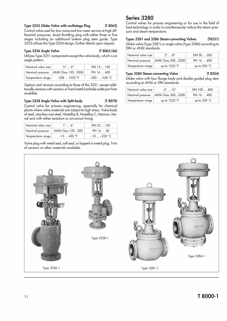
Type 3255 Globe Valve with multistage Plug (T 8062)Control valve used for low-noise and low-wear service at high dif-ferential pressures. Axial throttling plug with either three or fivestages including an additional bottom plug stem guide. Type3255 utilizes the Type 3254 design, further details upon request.
Type 3256 Angle Valve (T 8065/66)Utilizes Type 3251 components except the valve body, which is anangle pattern.
Nominal valve size ½” ... 6” DN 15 ... 150
Nominal pressure ANSI Class 150...2500 PN 16 ... 400
Temperature range −328 ... 1022 °F −200 ... +550 °C
Options and versions according to those of the 3251, except addi-tionally versions with ceramic or hard metal (carbide) outlet port lineravailable.
Type 3258 Angle Valve with Split-body (T 8070)Control valve for process engineering, especially for chemicalplants where valve materials are subject to high stress. Valve bodyof steel, stainless cast steel, Hastelloy B, Hastelloy C, titanium, Mo-nel and with either tantalum or zirconium lining.
Nominal valve size 1” ... 6” DN 25 ... 150
Nominal pressure ANSI Class 150...300 PN 16 ... 40
Temperature range −15 ... 430 °F −10 ... +220 °C
Valve plug with metal seal, soft seal, or lapped-in metal plug. Trimof ceramic or other materials available.
Series 3280Control valves for process engineering or for use in the field ofheat technology in order to simultaneously reduce the steam pres-sure and steam temperature.
Types 3281 and 3286 Steam-converting Valves (T8251)Globe valve (Type 3281) or angle valve (Type 3286) according toDIN or ANSI standards.
Nominal valve size 2” ... 8” DN 50 ... 200
Nominal pressure ANSI Class 300...2500 PN 16 ... 400
Temperature range up to 1022 °F up to 550 °C
Type 3284 Steam-converting Valve (T 8254)Globe valve with four-flange body and double-guided plug stemaccording to ANSI or DIN standards.
Nominal valve size 4” ... 16” DN 100 ... 400
Nominal pressure ANSI Class 300...2500 PN 16 ... 400
Temperature range up to 1022 °F up to 550 °C
11 T 8000-1
Type 3281-1
Type 3284-1
Type 3256-1
Type 3258-1
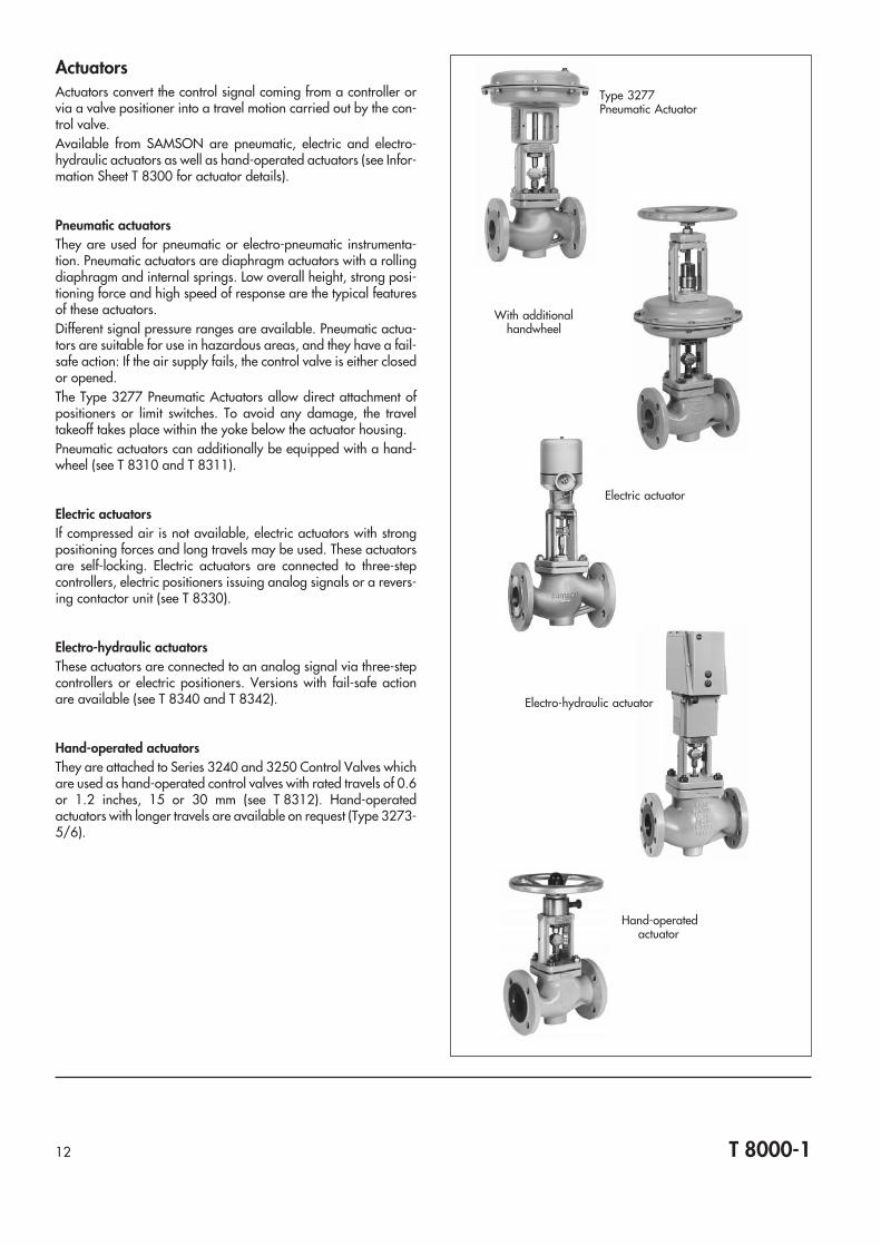
ActuatorsActuators convert the control signal coming from a controller orvia a valve positioner into a travel motion carried out by the con-trol valve.Available from SAMSON are pneumatic, electric and electro-hydraulic actuators as well as hand-operated actuators (see Infor-mation Sheet T 8300 for actuator details).
Pneumatic actuatorsThey are used for pneumatic or electro-pneumatic instrumenta-tion. Pneumatic actuators are diaphragm actuators with a rollingdiaphragm and internal springs. Low overall height, strong posi-tioning force and high speed of response are the typical featuresof these actuators.Different signal pressure ranges are available. Pneumatic actua-tors are suitable for use in hazardous areas, and they have a fail-safe action: If the air supply fails, the control valve is either closedor opened.The Type 3277 Pneumatic Actuators allow direct attachment ofpositioners or limit switches. To avoid any damage, the traveltakeoff takes place within the yoke below the actuator housing.Pneumatic actuators can additionally be equipped with a hand-wheel (see T 8310 and T 8311).
Electric actuatorsIf compressed air is not available, electric actuators with strongpositioning forces and long travels may be used. These actuatorsare self-locking. Electric actuators are connected to three-stepcontrollers, electric positioners issuing analog signals or a revers-ing contactor unit (see T 8330).
Electro-hydraulic actuatorsThese actuators are connected to an analog signal via three-stepcontrollers or electric positioners. Versions with fail-safe actionare available (see T 8340 and T 8342).
Hand-operated actuatorsThey are attached to Series 3240 and 3250 Control Valves whichare used as hand-operated control valves with rated travels of 0.6or 1.2 inches, 15 or 30 mm (see T 8312). Hand-operatedactuators with longer travels are available on request (Type 3273-5/6).
T 8000-112
Type 3277Pneumatic Actuator
With additionalhandwheel
Electric actuator
Electro-hydraulic actuator
Hand-operatedactuator

Accessories for Control ValvesSAMSON Control Valves can be equipped with several addi-tional accessories. These accessories are e.g. used for actuatorcontrol and travel indication. They are attached either accordingto EN 60 534 (NAMUR rib) or directly with the Type 3277 Pneu-matic Actuator up to size 700 (area in cm2). For direct attach-ment, the entire travel linkage is located in a closed housing in or-der to avoid contamination, mis-adjustment and also possible in-juries of the personnel (for details, see Information Sheet T 8350).
PositionerPositioners (p/p or i/p) compare the signal of a pneumatic orelectric control system (e.g. 3 ... 15 psi, 0.2 ... 1 bar or4(0) ... 20 mA) to the travel (manipulated variable) of the controlvalve. They issue a pneumatic signal pressure (psp) as output vari-able. The positioners can be used in standard operation or in split-range operation (see T 8351 onwards). Smart versions are con-figured and operated with the help of a PC or a handheld commu-nicator (see T 8380).
Limit switchWhenever an adjustable limit value is exceeded or not reached, asignal is sent out. Inductive limit switches are the preferred version.However, versions with electric or pneumatic microswitches arealso available (see Information Sheet T 8350).
Position transmitter / PotentiometerTo indicate the travel position of a control valve, the rated travelrange is represented by an analog electric signal (see T 8363).
Solenoid valveThe binary signals of a control system are converted into binarypneumatic control signals. As a result, the control valve canquickly be brought to its final position. The solenoid valves areused for ON/OFF valves or for control valves with fail-safe action.
Lockup valveIf the supply air pressure falls below an adjusted value, the signalpressure line is shut off. When this happens, the actuator stops onits last position (see T 8391).
Pneumatic remote adjusterManually adjustable precision regulator for the set point adjust-ment of pneumatic control systems.
Supply pressure regulatorThe supply pressure regulator provides pneumatic control valveswith a constant air pressure (adjustable between 0 and 60 psi,0 and 6 bar) (see T 8545).
Air pressure reducing stationThis station consists of a supply pressure regulator and an air filterholding back foreign particles, oil and/or condensate (seeT 8545).
Pneumatic amplifierFor fast control loops, the actuating time can be made shorter bymeans of pneumatic volume amplifiers.
T 8000-113
Pneumatic remote adjuster
Supply pressure regulator and Air pressure reducing station
Lockup valve
Solenoid valve
Position transmitter orPotentiometer
Limit switch
Positioner
Control Valves in Detail
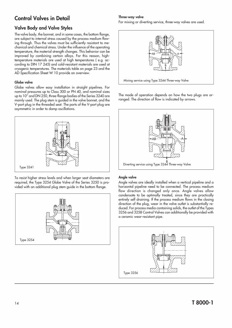
Valve Body and Valve StylesThe valve body, the bonnet, and in some cases, the bottom flange,are subject to internal stress caused by the process medium flow-ing through. Thus the valves must be sufficiently resistant to me-chanical and chemical stress. Under the influence of the operatingtemperature, the material strength changes. This behavior can beimproved by combining certain alloys. For this reason, high-temperature materials are used at high temperatures ( e.g. ac-cording to DIN 17 245) and cold-resistant materials are used atcryogenic temperatures. The materials table on page 23 and theAD Specification Sheet W 10 provide an overview.
Globe valveGlobe valves allow easy installation in straight pipelines. Fornominal pressures up to Class 300 or PN 40, and nominal sizesup to 10” and DN 250, three-flange bodies of the Series 3240 aremainly used. The plug stem is guided in the valve bonnet, and theV-port plug in the threaded seat. The ports of the V-port plug areasymmetric in order to damp oscillations.
To resist higher stress levels and when larger seat diameters arerequired, the Type 3254 Globe Valve of the Series 3250 is pro-vided with an additional plug stem guide in the bottom flange.
Three-way valveFor mixing or diverting service, three-way valves are used.
The mode of operation depends on how the two plugs are ar-ranged. The direction of flow is indicated by arrows.
Angle valveAngle valves are ideally installed when a vertical pipeline and ahorizontal pipeline need to be connected. The process mediumflow direction is changed only once. Angle valves allowcondensate to be optimally treated, since they are practicallyentirely self draining. If the process medium flows in the closingdirection of the plug, wear in the valve outlet is substantially re-duced. For process media containing solids, the outlet of the Types3256 and 3258 Control Valves can additionally be provided witha ceramic wear-resistant pipe.
14 T 8000-1
Type 3254
Type 3256
AB A
B
Mixing service using Type 3244 Three-way Valve
AB A
BDiverting service using Type 3244 Three-way Valve
Type 3241

Split-body valveThe split-body valves are almost free of dead space, and due totheir style, they can be manufactured of steel as well as of Hastel-loy, titanium or Monel. The simple geometric shape allows trimsand linings of tantalum, zirconium and ceramic to be used as aprotection against abrasive process media.
Cryogenic valveIn plants producing liquefied cryogenic gases, vacuum-insulatedpipelines are often used in order to avoid environmental heat tobe transferred to the medium. The control valves can be integratedin the vacuum jacket by means of a connecting flange. Construc-tional measures widely prevent thermal conduction to the effectthat the stem remains free of ice. The primary sealing is a bellowsseal. The jacketed pipeline is sealed and evacuated after the in-stallation of the components. The temperature-insulating exten-sion of the control valves is often welded to the jacketed pipelinevia a flange, and therefore considerable efforts are necessarywhen the valve is to be removed from the pipeline. However, tomake maintenance possible, the internal parts can be accessedvia the temperature-insulating extension without the need to re-move the valve from the pipeline.
Valves for food processingValves for food processing are angle valves made of stainlesssteel. The internal surfaces exposed to the process medium areprecision machined or polished. The valve bodies are self drain-ing and can be cleaned (CIP) or sterilized (SIP) “in-place” (withoutbeing disassembled). The stem is sealed with a special dia-phragm, thus preventing the trapping of bacteria.
The Type 3347 Control Valve can be supplied with weld-on fittings, athreaded or a clamp connection according to ISO 2852, and with asteam trap if higher purity requirements are to be met.
Diaphragm control valveFor viscous or corrosive media possibly containing solids,diaphragm control valves free of dead space and without stuffingboxes are an economical solution. The diaphragm may be madeof rubber, nitrile, butyl or PTFE. The valve body may additionallybe lined with rubber or PTFE.
15 T 8000-1
Type 3248
Type 3249
Type 3345
Type 3258
Type 3347
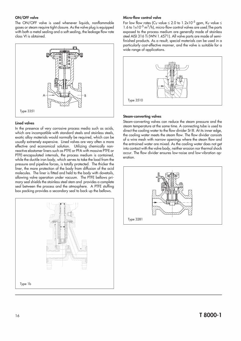
ON/OFF valveThe ON/OFF valve is used whenever liquids, nonflammablegases or steam require tight closure. As the valve plug is equippedwith both a metal sealing and a soft sealing, the leakage flow rateclass VI is obtained.
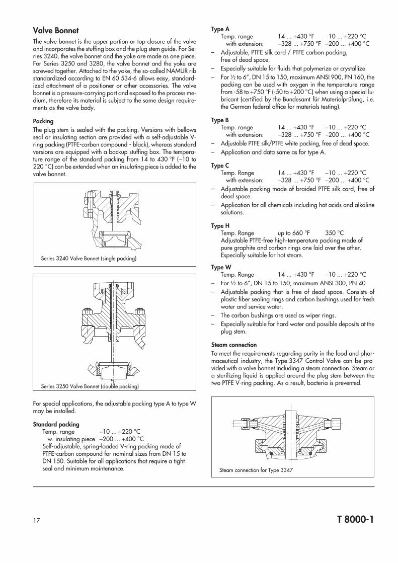
Lined valvesIn the presence of very corrosive process media such as acids,which are incompatible with standard steels and stainless steels,exotic alloy materials would normally be required, which can beusually extremely expensive. Lined valves are very often a moreeffective and economical solution. Utilizing chemically non-reactive elastomer liners such as PTFE or PFA with massive PTFE orPTFE-encapsulated internals, the process medium is contained,while the ductile iron body, which serves to take the load from thepressure and pipeline forces, is totally protected. The thicker theliner, the more protection of the body from diffusion of the acidmolecules. The liner is fitted and held to the body with dovetails,allowing valve operation under vacuum. The PTFE bellows pri-mary seal shields the stainless steel stem and provides a completeseal between the process and the atmosphere. A PTFE stuffingbox packing provides a secondary seal to back up the bellows.
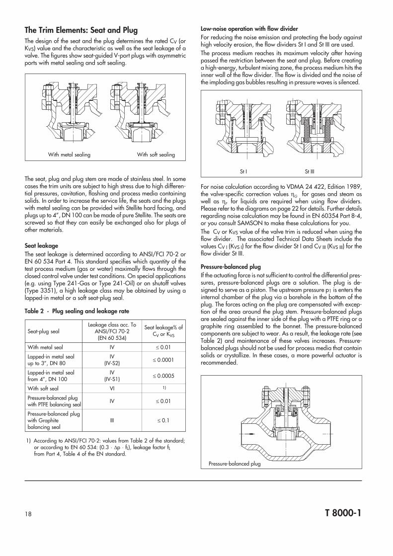
Micro-flow control valveFor low flow rates (CV value ≤ 2.0 to 1.2x10⁻⁵ gpm, KV value ≤1.6 to 1x10⁻⁵ m3/h), micro-flow control valves are used.The partsexposed to the process medium are generally made of stainlesssteel AISI 316 Ti (WN 1.4571). All valve parts are made of semi-finished products. As a result, special materials can be used in aparticularly cost-effective manner, and the valve is suitable for awide range of applications.
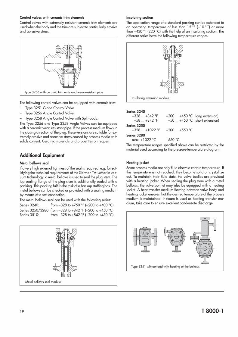
Steam-converting valvesSteam-converting valves can reduce the steam pressure and thesteam temperature at the same time. A connecting tube is used todirect the cooling water to the flow divider St III. At its inner edge,the cooling water meets the steam flow. The flow divider consistsof a wire mesh with narrow openings where the steam flow andthe entrained water are mixed. As the cooling water does not getinto contact with the valve body, neither erosion nor thermal shockoccur. The flow divider ensures low-noise and low-vibration op-eration.
16 T 8000-1
Type 3510
Type 3281
A B
Type 3351
Type 1b
Valve BonnetThe valve bonnet is the upper portion or top closure of the valveand incorporates the stuffing box and the plug stem guide. For Se-ries 3240, the valve bonnet and the yoke are made as one piece.For Series 3250 and 3280, the valve bonnet and the yoke arescrewed together. Attached to the yoke, the so-called NAMUR ribstandardized according to EN 60 534-6 allows easy, standard-ized attachment of a positioner or other accessories. The valvebonnet is a pressure-carrying part and exposed to the process me-dium, therefore its material is subject to the same design require-ments as the valve body.
PackingThe plug stem is sealed with the packing. Versions with bellowsseal or insulating section are provided with a self-adjustable V-ring packing (PTFE-carbon compound - black), whereas standardversions are equipped with a backup stuffing box. The tempera-ture range of the standard packing from 14 to 430 °F (−10 to220 °C) can be extended when an insulating piece is added to thevalve bonnet.
For special applications, the adjustable packing type A to type Wmay be installed.
Standard packingTemp. range −10 ... +220 °C
w. insulating piece −200 ... +400 °CSelf-adjustable, spring-loaded V-ring packing made ofPTFE-carbon compound for nominal sizes from DN 15 toDN 150. Suitable for all applications that require a tightseal and minimum maintenance.
Type ATemp. range 14 ... +430 °F −10 ... +220 °C
with extension: −328 ... +750 °F −200 ... +400 °C– Adjustable, PTFE silk cord / PTFE carbon packing,
free of dead space.– Especially suitable for fluids that polymerize or crystallize.– For ½ to 6”, DN 15 to 150, maximum ANSI 900, PN 160, the
packing can be used with oxygen in the temperature rangefrom -58 to +750 °F (-50 to +200 °C) when using a special lu-bricant (certified by the Bundesamt für Materialprüfung, i.e.the German federal office for materials testing).
Type BTemp. range 14 ... +430 °F −10 ... +220 °C
with extension: −328 ... +750 °F −200 ... +400 °C– Adjustable PTFE silk/PTFE white packing, free of dead space.– Application and data same as for type A.
Type CTemp. Range 14 ... +430 °F −10 ... +220 °C
with extension: −328 ... +750 °F −200 ... +400 °C– Adjustable packing made of braided PTFE silk cord, free of
dead space.– Application for all chemicals including hot acids and alkaline
solutions.
Type HTemp. Range up to 660 °F 350 °CAdjustable PTFE-free high-temperature packing made ofpure graphite and carbon rings one laid over the other.Especially suitable for hot steam.
Type WTemp. Range 14 ... +430 °F −10 ... +220 °C
– For ½ to 6”, DN 15 to 150, maximum ANSI 300, PN 40– Adjustable packing that is free of dead space. Consists of
plastic fiber sealing rings and carbon bushings used for freshwater and service water.
– The carbon bushings are used as wiper rings.– Especially suitable for hard water and possible deposits at the
plug stem.
Steam connectionTo meet the requirements regarding purity in the food and phar-maceutical industry, the Type 3347 Control Valve can be pro-vided with a valve bonnet including a steam connection. Steam ora sterilizing liquid is applied around the plug stem between thetwo PTFE V-ring packing. As a result, bacteria is prevented.
T 8000-117
Steam connection for Type 3347
Series 3240 Valve Bonnet (single packing)
Series 3250 Valve Bonnet (double packing)
The Trim Elements: Seat and PlugThe design of the seat and the plug determines the rated CV (orKVS) value and the characteristic as well as the seat leakage of avalve. The figures show seat-guided V-port plugs with asymmetricports with metal sealing and soft sealing.
The seat, plug and plug stem are made of stainless steel. In somecases the trim units are subject to high stress due to high differen-tial pressures, cavitation, flashing and process media containingsolids. In order to increase the service life, the seats and the plugswith metal sealing can be provided with Stellite hard facing, andplugs up to 4”, DN 100 can be made of pure Stellite. The seats arescrewed so that they can easily be exchanged also for plugs ofother materials.
Seat leakageThe seat leakage is determined according to ANSI/FCI 70-2 orEN 60 534 Part 4. This standard specifies which quantity of thetest process medium (gas or water) maximally flows through theclosed control valve under test conditions. On special applications(e.g. using Type 241-Gas or Type 241-Oil) or on shutoff valves(Type 3351), a high leakage class may be obtained by using alapped-in metal or a soft seat-plug seal.
Table 2 · Plug sealing and leakage rate
Seat-plug sealLeakage class acc. To
ANSI/FCI 70-2(EN 60 534)
Seat leakage% ofCV or KVS
With metal seal IV ≤ 0.01
Lapped-in metal sealup to 3”, DN 80
IV(IV-S2) ≤ 0.0001
Lapped-in metal sealfrom 4”, DN 100
IV(IV-S1) ≤ 0.0005
With soft seal VI 1)
Pressure-balanced plugwith PTFE balancing seal IV ≤ 0.01
Pressure-balanced plugwith Graphitebalancing seal
III ≤ 0.1
1) According to ANSI/FCI 70-2: values from Table 2 of the standard;or according to EN 60 534: (0.3 · ∆p · fL), leakage factor fLfrom Part 4, Table 4 of the EN standard.
Low-noise operation with flow dividerFor reducing the noise emission and protecting the body againsthigh velocity erosion, the flow dividers St I and St III are used.The process medium reaches its maximum velocity after havingpassed the restriction between the seat and plug. Before creatinga high-energy, turbulent mixing zone, the process medium hits theinner wall of the flow divider. The flow is divided and the noise ofthe imploding gas bubbles resulting in pressure waves is silenced.
For noise calculation according to VDMA 24 422, Edition 1989,the valve-specific correction values ηG for gases and steam aswell as ηF for liquids are required when using flow dividers.Please refer to the diagrams on page 22 for details. Further detailsregarding noise calculation may be found in EN 60354 Part 8-4,or you consult SAMSON to make these calculations for you.The CV or KVS value of the valve trim is reduced when using theflow divider. The associated Technical Data Sheets include thevalues CV I (KVS I) for the flow divider St I and CV III (KVS III) for theflow divider St III.
Pressure-balanced plugIf the actuating force is not sufficient to control the differential pres-sures, pressure-balanced plugs are a solution. The plug is de-signed to serve as a piston. The upstream pressure p1 is enters theinternal chamber of the plug via a borehole in the bottom of theplug. The forces acting on the plug are compensated with excep-tion of the area around the plug stem. Pressure-balanced plugsare sealed against the inner side of the plug with a PTFE ring or agraphite ring assembled to the bonnet. The pressure-balancedcomponents are subject to wear. As a result, the leakage rate (seeTable 2) and maintenance of these valves increases. Pressure-balanced plugs should not be used for process media that containsolids or crystallize. In these cases, a more powerful actuator isrecommended.
18 T 8000-1
With metal sealing With soft sealing
St I St III
Pressure-balanced plug
Control valves with ceramic trim elementsControl valves with extremely resistant ceramic trim elements areused when the body and the trim are subject to particularly erosiveand abrasive stress.
The following control valves can be equipped with ceramic trim:– Type 3251 Globe Control Valve– Type 3256 Angle Control Valve– Type 3258 Angle Control Valve with Split-body.The Type 3256 and Type 3258 Angle Valves can be equippedwith a ceramic wear-resistant pipe. If the process medium flows inthe closing direction of the plug, these versions are suitable for ex-tremely erosive and abrasive stress caused by process media withsolids content. Ceramic materials and properties on request.
Additional EquipmentMetal bellows sealIf a very high external tightness of the seal is required, e.g. for sat-isfying the technical requirements of the German TA-Luft or in vac-uum technology, a metal bellows is used to seal the plug stem. Thetop sealing flange of the plug stem is additionally sealed with apacking. This packing fulfills the task of a backup stuffing box. Themetal bellows can be checked or provided with a sealing mediumby means of a test connection.The metal bellows seal can be used with the following series:Series 3240: from −328 to +750 °F (−200 to +400 °C)Series 3250/3280: from −328 to +842 °F (−200 to +450 °C)Series 3510: from −328 to +842 °F (−200 to +450 °C)
Insulating sectionThe application range of a standard packing can be extended toan operating temperature of less than 15 °F (−10 °C) or morethan +430 °F (220 °C) with the help of an insulating section. Thedifferent series have the following temperature ranges:
Series 3240−328 ... +842 °F −200 ... +450 °C (long extension)
−58 ... +842 °F −50 ... +450 °C (short extension)Series 3250
−328 ... +1022 °F −200 ... +550 °CSeries 3280
max. +1022 °C +550 °CThe temperature ranges specified above can be restricted by thematerial used according to the pressure-temperature diagram.
Heating jacketSome process media are only fluid above a certain temperature. Ifthis temperature is not reached, they become solid or crystallizeout. To maintain their fluid state, the valve bodies are providedwith a heating jacket. When sealing the plug stem with a metalbellows, the valve bonnet may also be equipped with a heatingjacket. A heat transfer medium flowing between valve body andheating jacket ensures that the desired temperature of the processmedium is maintained. If steam is used as heating transfer me-dium, take care to ensure excellent condensate discharge.
T 8000-119
Type 3256 with ceramic trim units and wear-resistant pipe
Type 3241 without and with heating of the bellows
Metal bellows seal module
Insulating extension module
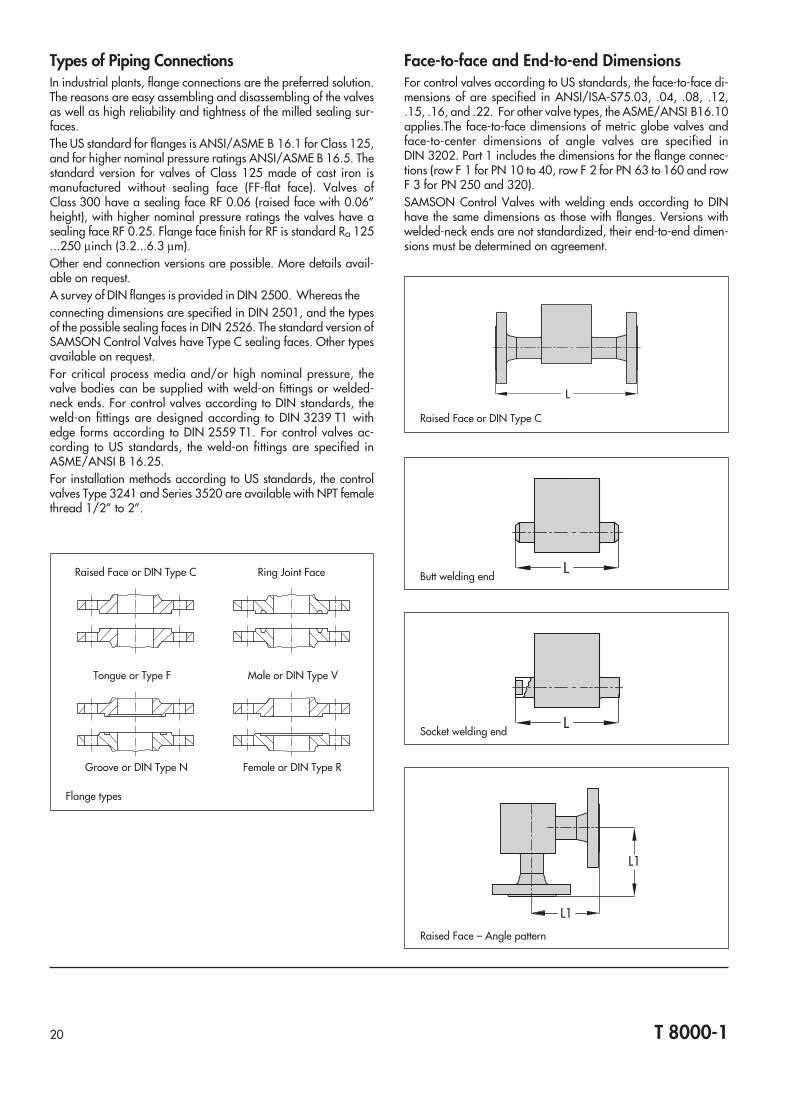
Types of Piping ConnectionsIn industrial plants, flange connections are the preferred solution.The reasons are easy assembling and disassembling of the valvesas well as high reliability and tightness of the milled sealing sur-faces.The US standard for flanges is ANSI/ASME B 16.1 for Class 125,and for higher nominal pressure ratings ANSI/ASME B 16.5. Thestandard version for valves of Class 125 made of cast iron ismanufactured without sealing face (FF-flat face). Valves ofClass 300 have a sealing face RF 0.06 (raised face with 0.06”height), with higher nominal pressure ratings the valves have asealing face RF 0.25. Flange face finish for RF is standard Ra 125...250 µinch (3.2...6.3 µm).Other end connection versions are possible. More details avail-able on request.A survey of DIN flanges is provided in DIN 2500. Whereas theconnecting dimensions are specified in DIN 2501, and the typesof the possible sealing faces in DIN 2526. The standard version ofSAMSON Control Valves have Type C sealing faces. Other typesavailable on request.For critical process media and/or high nominal pressure, thevalve bodies can be supplied with weld-on fittings or welded-neck ends. For control valves according to DIN standards, theweld-on fittings are designed according to DIN 3239 T1 withedge forms according to DIN 2559 T1. For control valves ac-cording to US standards, the weld-on fittings are specified inASME/ANSI B 16.25.For installation methods according to US standards, the controlvalves Type 3241 and Series 3520 are available with NPT femalethread 1/2” to 2”.
Face-to-face and End-to-end DimensionsFor control valves according to US standards, the face-to-face di-mensions of are specified in ANSI/ISA-S75.03, .04, .08, .12,.15, .16, and .22. For other valve types, the ASME/ANSI B16.10applies.The face-to-face dimensions of metric globe valves andface-to-center dimensions of angle valves are specified inDIN 3202. Part 1 includes the dimensions for the flange connec-tions (row F 1 for PN 10 to 40, row F 2 for PN 63 to 160 and rowF 3 for PN 250 and 320).SAMSON Control Valves with welding ends according to DINhave the same dimensions as those with flanges. Versions withwelded-neck ends are not standardized, their end-to-end dimen-sions must be determined on agreement.
T 8000-120
L
Raised Face or DIN Type C
LButt welding end
L1
L1
Raised Face – Angle pattern
LSocket welding end
Raised Face or DIN Type C Ring Joint Face
Tongue or Type F Male or DIN Type V
Groove or DIN Type N Female or DIN Type R
Flange types

T 8000-121
Table 3a · Face-to-face and end-to-end dimensions for globecontrol valves according to ISA and IEC · Dimensions ininches
ISA dimension “L”inches
Flanged 1)Short Pattern
Class 150, 300, 600(Grp 1 PN 20,50,100)
Nominal valve size Class 150(PN 20),
Class 125
Class 300(PN 50),
Class 250
Socketweld 2) Butt weld 3)
inches mm
½ 15 7.25 7.50 6.69 7.38
¾ 20 7.25 7.62 6.69 7.38
1 25 7.25 7.75 7.75 7.38
1½ 40 8.75 9.25 9.25 8.75
2 50 10.00 10.50 10.50 10.00
2½ 65 10.88 11.50 11.50 11.50
3 80 11.75 12.50 12.50 12.50
4 100 13.88 14.50 14.50 14.50
6 150 17.75 18.62 – 17.75
8 200 21.38 22.38 – 21.38
10 250 26.50 27.88 – 26.50
12 300 29.00 30.50 – 29.00
14 350 35.00 36.50 – 33.50
16 400 40.00 41.62 – 40.00
FF–Flat Face RF–Raised Face SWE–Socket welding ends BWE–Buttwelding endsShaded cells refer to less customary versions. Check with SAMSON foravailability, before ordering.1) ISA-S75.03 and IEC 60534-3-1, Table I2) ISA-S75.123) ISA-S75.15 and IEC 60534-3-3
Table 4a · Face-to-face and end-to-end dimensions for globecontrol valves according to ISA and IEC · Dimensions ininches
ISA dimension “L”inches
Flanged 1)Long Pattern
Class 150, 300, 600(Group 2 PN 20, 50, 100)
Nominal valve size Class 600(PN 100) Socket
weld 2) Butt weld 3)inches mm
½ 15 8.00 8.12 8.00
¾ 20 8.12 8.25 8.25
1 25 8.25 8.25 8.25
1½ 40 9.88 9.88 9.88
2 50 11.25 11.25 11.25
2½ 65 12.25 12.25 12.25
3 80 13.25 13.25 13.25
4 100 15.50 15.50 15.50
6 150 20.00 – 20.00
8 200 24.00 – 24.00
10 250 29.62 – 29.62
12 300 32.25 – 32.35
14 350 38.25 – 40.50
16 400 43.62 – 43.62
RF–Raised Face SWE–Socket welding ends BWE–Butt welding endsShaded cells refer to less customary versions. Check with SAMSON foravailability, before ordering.1) ISA-S75.03 and IEC 60534-3-1, Table I2) ISA-S75.123) ISA-S75.15 and IEC 60534-3-3
Table 6a · End-to-end dimensions for globe control valveswith ring joint facings · Dimensions in inches
Nominal valve size Class 150(ISO PN 20)
Class 300(ISO PN 50)
Class 600(ISO PN 100)inches mm
½ 15 7.25 + 0.50 7.50 + 0.44 8.00 – 0.06
¾ 20 7.25 + 0.50 7.62 + 0.50 8.12 + 0.00
1 25 7.25 + 0.50 7.75 + 0.50 8.25 + 0.00
1½ 40 8.75 + 0.50 9.25 + 0.50 9.88 + 0.00
2 50 10.00 + 0.50 10.50 + 0.62 11.25 + 0.12
2½ 65 10.88 + 0.50 11.50 + 0.62 12.25 + 0.12
3 80 11.75 + 0.50 12.50 + 0.62 13.25 + 0.12
4 100 13.88 + 0.50 14.50 + 0.62 15.50 + 0.12
6 150 17.75 + 0.50 18.62 + 0.62 20.00 + 0.12
8 200 21.38 + 0.50 22.38 + 0.62 24.00 + 0.12
10 250 26.50 + 0.50 27.88 + 0.62 29.62 + 0.12
12 300 29.00 + 0.50 30.50 + 0.62 32.25 + 0.12
14 350 35.00 + 0.50 36.50 + 0.62 38.25 + 0.12
16 400 40.00 + 0.50 41.62 + 0.62 43.62 + 0.12
According to ISA-S75.03 and ASME B16.10
Table 5a · Face-to-centerline dimensions for flanged globe-style angle control valves · Dimension “L1” in inches
Nominal valve size Class 150(ISO PN 20)
Class 300(ISO PN 50)
Class 600(ISO PN 100)inches mm
½ 15 – – –
¾ 20 – – –
1 25 3.62 3.88 4.12
1½ 40 4.37 4.62 4.94
2 50 5.00 5.25 5.62
2½ 65 – – –
3 80 5.88 6.25 6.62
4 100 6.94 7.25 7.75
6 150 8.88 9.31 10.00
8 200 10.69 11.19 12.00
According to ISA-S75.22

T 8000-122
Table 6b · End-to-end dimensions for globe control valveswith ring joint facings · Dimensions in millimeters
Nominal valve size Class 150(ISO PN 20)
Class 300(ISO PN 50)
Class 600(ISO PN 100)inches mm
½ 15 184+13=197 190+11=201 203-1.5=201
¾ 20 184+13=197 194+13=207 206+0=206
1 25 184+13=197 197+13=210 210+0=210
1½ 40 222+13=235 235+13=248 251+0=251
2 50 254+13=267 267+16=283 286+3=289
2½ 65 276+13=289 292+16=308 311+3=314
3 80 298+13=311 318+16=333 337+3=340
4 100 352+13=365 368+16=384 394+3=397
6 150 451+13=464 473+16=489 508+3=511
8 200 543+13=556 568+16=584 610+3=613
10 250 673+13=686 708+16=724 752+3=755
12 300 737+13=750 775+16=791 819+3=822
14 350 889+13=902 927+16=943 972+3=975
16 400 1016+13=1029 1057+16=1074 1108+3=1111
According to ISA-S75.03 and ASME B16.10
Table 3b · Face-to-face and end-to-end dimensions for globecontrol valves according to ISA and IEC · Dimensions in mm
ISA dimension “L”mm
Flanged 1)Short Pattern
Class 150, 300, 600(Grp 1 PN 20,50,100)
Nominal valve size Class 150(PN 20),
Class 125
Class 300(PN 50),
Class 250
Socketweld 2) Butt weld 3)
inches mm
½ 15 184 190 170 187
¾ 20 184 194 170 187
1 25 184 197 197 187
1½ 40 222 235 235 222
2 50 254 267 267 254
2½ 65 276 292 292 292
3 80 298 318 318 318
4 100 352 368 368 368
6 150 451 473 – 451
8 200 543 568 – 543
10 250 673 708 – 673
12 300 737 775 – 737
14 350 889 927 – 851
16 400 1016 1057 – 1016
FF–Flat Face RF–Raised Face SWE–Socket welding ends BWE–Buttwelding endsShaded cells refer to less customary versions. Check with SAMSON foravailability, before ordering.1) ISA-S75.03 and IEC 60534-3-1, Table I2) ISA-S75.123) ISA-S75.15 and IEC 60534-3-3
Table 4b · Face-to-face and end-to-end dimensions for globecontrol valves according to ISA and IEC · Dimensions in mm
ISA dimension “L”mm
Flanged 1)Long Pattern
Class 150, 300, 600(Group 2 PN 20, 50, 100)
Nominal valve size Class 600(PN 100) Socket
weld 2) Butt weld 3)inches mm
½ 15 203 206 203
¾ 20 206 210 206
1 25 210 210 210
1½ 40 251 251 251
2 50 286 286 286
2½ 65 311 311 311
3 80 337 337 337
4 100 394 394 394
6 150 508 508
8 200 610 610
10 250 752 752
12 300 819 819
14 350 972 1029
16 400 1108 1108
RF–Raised Face SWE–Socket welding ends BWE–Butt welding endsShaded cells refer to less customary versions. Check with SAMSON foravailability, before ordering.1) ISA-S75.03 and IEC 60534-3-1, Table I2) ISA-S75.123) ISA-S75.15 and IEC 60534-3-3
Table 5b · Face-to-centerline dimensions for flanged globe-style angle control valves · Dimension “L1” in mm
Nominal valve size Class 150(ISO PN 20)
Class 300(ISO PN 50)
Class 600(ISO PN 100)inches mm
½ 15 – – –
¾ 20 – – –
1 25 92 99 105
1½ 40 111 117 125
2 50 127 133 143
2½ 65 – – –
3 80 149 159 168
4 100 176 184 197
6 150 226 236 254
8 200 272 284 305
According to ISA-S75.22
Valve-specific Parameters
Flow coefficientsCV valueThe necessary CV value is calculated according to ISA-S75.01 orEN 60534 using the specified operating data.For the designation of the valves, the CV value is specified in theTechnical Data Sheets. The valve CV100 value corresponds to theCV value for the nominal travel height H100. In order to increasecontrol accuracy and with regard to the manufacturing toler-ances, the CV or value chosen is to be higher than the CV valuecalculated.
KV valueThe KV value is the alternative flow coefficient as defined by EN60534. The conversion is CV ≈ 1.17· KV.
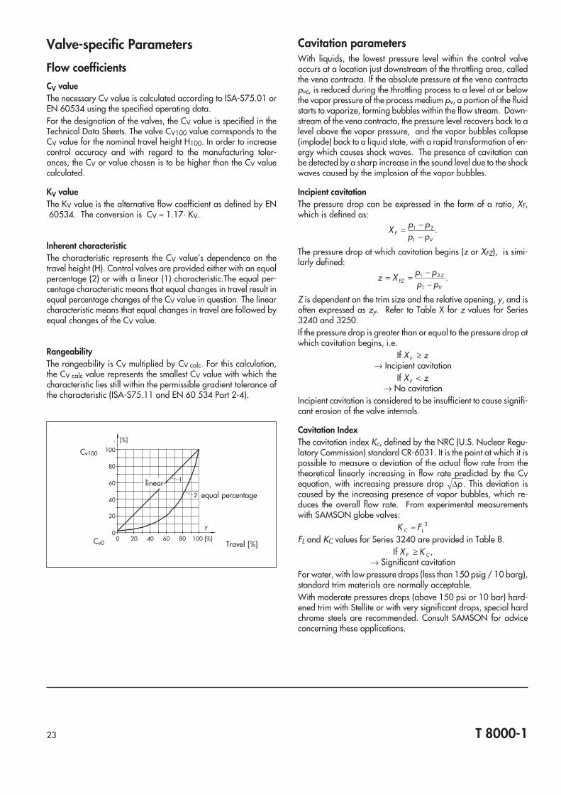
Inherent characteristicThe characteristic represents the CV value’s dependence on thetravel height (H). Control valves are provided either with an equalpercentage (2) or with a linear (1) characteristic.The equal per-centage characteristic means that equal changes in travel result inequal percentage changes of the CV value in question. The linearcharacteristic means that equal changes in travel are followed byequal changes of the CV value.
RangeabilityThe rangeability is CV multiplied by CV calc. For this calculation,the CV calc value represents the smallest CV value with which thecharacteristic lies still within the permissible gradient tolerance ofthe characteristic (ISA-S75.11 and EN 60 534 Part 2-4).
Cavitation parametersWith liquids, the lowest pressure level within the control valveoccurs at a location just downstream of the throttling area, calledthe vena contracta. If the absolute pressure at the vena contractapvc, is reduced during the throttling process to a level at or belowthe vapor pressure of the process medium pv, a portion of the fluidstarts to vaporize, forming bubbles within the flow stream. Down-stream of the vena contracta, the pressure level recovers back to alevel above the vapor pressure, and the vapor bubbles collapse(implode) back to a liquid state, with a rapid transformation of en-ergy which causes shock waves. The presence of cavitation canbe detected by a sharp increase in the sound level due to the shockwaves caused by the implosion of the vapor bubbles.
Incipient cavitationThe pressure drop can be expressed in the form of a ratio, XF,which is defined as:
X p pp pF
V
= −−
1 2
1
.
The pressure drop at which cavitation begins (z or XFZ), is simi-larly defined:
z X p pp pFZ
Z
V
= = −−
1 2
1
.
Z is dependent on the trim size and the relative opening, y, and isoften expressed as zy. Refer to Table X for z values for Series3240 and 3250.If the pressure drop is greater than or equal to the pressure drop atwhich cavitation begins, i.e.
If X zF ≥→ Incipient cavitation
If X zF <→ No cavitation
Incipient cavitation is considered to be insufficient to cause signifi-cant erosion of the valve internals.
Cavitation IndexThe cavitation index Kc, defined by the NRC (U.S. Nuclear Regu-latory Commission) standard CR-6031. It is the point at which it ispossible to measure a deviation of the actual flow rate from thetheoretical linearly increasing in flow rate predicted by the CVequation, with increasing pressure drop ∆p. This deviation iscaused by the increasing presence of vapor bubbles, which re-duces the overall flow rate. From experimental measurementswith SAMSON globe valves:
K FC L≈ 3
FL and KC values for Series 3240 are provided in Table 8.If X KF C≥ ,
→ Significant cavitationFor water, with low pressure drops (less than 150 psig / 10 barg),standard trim materials are normally acceptable.With moderate pressures drops (above 150 psi or 10 bar) hard-ened trim with Stellite or with very significant drops, special hardchrome steels are recommended. Consult SAMSON for adviceconcerning these applications.
23 T 8000-1
0 20 40 60 80 100 [%]
100
80
60
40
20
0
Kv [%]
y
1
2
Cv100
Travel [%]
linear
equal percentage
Cv0

T 8000-124
Table 7 · Nominal CV verses relative travel · 3240 Series · Equal percentage characteristic
Relative travel [%] 10 20 30 40 50 60 70 80 90 100
RatedCV
Valvesize
[inches]
Seatdiameter[inches]
Travel
[inches]
Range-ability
Nominal CV value
0.12 ½”to1”
0.12
0.650:1
0.004 0.005 0.008 0.011 0.017 0.025 0.037 0.055 0.081 0.120
0.2 0.006 0.009 0.013 0.019 0.028 0.042 0.062 0.091 0.135 0.200
0.3 0.009 0.013 0.019 0.029 0.042 0.063 0.093 0.137 0.203 0.300
0.5
½”to2”
0.24
0.015 0.022 0.032 0.048 0.071 0.105 0.155 0.229 0.338 0.500
0.75 0.022 0.033 0.049 0.072 0.106 0.157 0.232 0.343 0.507 0.750
1.2 0.035 0.052 0.078 0.115 0.170 0.251 0.371 0.549 0.811 1.20
2
0.47
0.059 0.087 0.129 0.191 0.283 0.418 0.618 0.915 1.35 2.00
3 0.089 0.131 0.194 0.287 0.424 0.627 0.928 1.37 2.03 3.00
5 0.148 0.219 0.323 0.478 0.707 1.05 1.55 2.29 3.38 5.00
7.5 ¾” to 2”0.95
0.222 0.328 0.485 0.717 1.06 1.57 2.32 3.43 5.07 7.50
12 1” to 2” 0.355 0.525 0.776 1.15 1.70 2.51 3.71 5.49 8.11 12.0
201½” to 3”
1.22 0.592 0.875 1.29 1.91 2.83 4.18 6.18 9.15 13.5 20.0
30 1.50 0.887 1.31 1.94 2.87 4.24 6.27 9.28 13.7 20.3 30.0
40 2” to 3” 1.90 1.18 1.75 2.59 3.83 5.66 8.37 12.4 18.3 27.0 40.0
70 2½” to 3” 2.48
30:1
3.28 4.61 6.47 9.10 12.8 18.0 25.2 35.5 49.8 70.0
75 4” to 6” 2.48 1.2 3.51 4.94 6.94 9.75 13.7 19.2 27.0 38.0 53.4 75.0
95 3” 3.15 0.6 4.45 6.25 8.78 12.3 17.3 24.4 34.2 48.1 67.6 95.0
1204” to 6”
3.151.2
5.62 7.90 11.1 15.6 21.9 30.8 43.3 60.8 85.4 120
190 3.94 8.90 12.5 17.6 24.7 34.7 48.7 68.5 96.2 135 190
290 8” to 10” 4.92 2.4 13.6 19.1 26.8 37.7 52.9 74.4 105 147 206 290
305 6” 5.12 1.2 14.3 20.1 28.2 39.6 55.7 78.2 110 154 217 305
4208” to 10”
5.912.4
19.7 27.6 38.8 54.6 76.7 108 151 213 299 420
735 7.87 34.4 48.4 68.0 95.5 134 189 265 372 523 735
Table 8 · FL, xT and Kc verses relative travel · 3240 Series · Flow to open valve
Relative travel [%] 10 20 30 40 50 60 70 80 90 100
Liquid pressure recovery factor(liquids, without attached fittings)
FL 0.96 0.95 0.94 0.93 0.92 0.91 0.91 0.90 0.90 0.90
Cavitation index (liquids) Kc 0.90 0.86 0.83 0.80 0.77 0.76 0.74 0.73 0.73 0.72
Pressure drop ratio factor (compressiblefluids, without attached fittings)
xT 0.79 0.76 0.75 0.73 0.71 0.70 0.70 0.69 0.69 0.68

Valve SizingCalculation of the Cv valueThe Cv value is calculated according to ISA-S75.01 and DIN IECEN 60 534. The Technical Data Sheets provide the necessarydevice-specific data. A simplified manual calculation may bemade with the help of the equations given below. They do not takeinto account the influence of the connecting fittings or the effectsunder non-turbulent (laminar or transitional) flow conditions.
Valve selectionAfter having calculated the Cv value, the corresponding Cv valueof the valve type in question is selected from the Technical DataSheet. If actual operating data have been used for the calculation,apply the following equations:C to CV V ratedmax
. .≈ ⋅0 7 0 8K to KV VSmax
. .≈ ⋅0 7 0 8For more information, refer to “Selection and Ordering informa-tion” on page 31
25 T 8000-1
Incompressible fluids (liquids)
Pressure drop Equations for pvcdetermination
Flow coefficient equation, with given units...
gpm, psi(a) lb/h, psi(a), lbm/ft3 m3/h, bar(a) kg/h, bar(a), kg/m3
Subcritical∆p F p pL vc< −2
1( )p F pvc F v=
F ppF
v
c
= − ⎛⎝⎜
⎞⎠⎟096 028
12
. .
C q Gp pV
f=−1 2
C wp p
V =−633 1 2 1. ( )ρ
C q Gp pV
f=−0865 1 2.
C wp p
V =−27 3 1 2 1. ( )ρ
Critical (choked)∆p F p pL vc≥ −2
1( ) C qF
Gp pV
L
f
vc
=−
max
1
C wF p p
V
L vc
=−
max
. ( )633 1 1ρC q
FG
p pVL
f
vc
=−
max
.0865 1
C wF p p
V
L vc
=−
max
. ( )27 3 1 1ρ
Compressible fluids (gases, vapors)
Pressure drop Equations for x, Fk , Y,determination
Flow coefficient equation, with given units...
Std ft3/h (scfh), psi(a), °R lb/h, psi(a), lbm/ft3 m3/h, bar(a), K kg/h, bar(a), kg/m3
Subcriticalx F xT< ⋅κ
x pp
= ∆
1
F κκ=
14.Y x
F xT
= −13 κ
C qp Y
G T Z
xVg=
1360 1
1 C wY xpV =
633 1 1. ρ C qp Y
G T Z
xVg=
417 1
1 C wY xpV =
27 3 1 1. ρ
Critical (choked)x F xT≥ ⋅κ
C qp
G T Z
F xVg
k T
= max
907 1
1 C wF x pV
k T
= max
.422 1 1ρC q
p
G T Z
F xVg
k T
= max
278 1
1 C wF x pV
k T
= max
.182 1 1ρ
Notes regarding the above equations:For exact results with valves with attached fittings (pipe reductions, elbows, etc.), the Piping geometry factor (FP) may be applied (C C FV V P= / ).For non-turbulent flow (laminar and transitional), the Reynolds number factor (FR) may be applied (C C FV V R= / ).Refer to the ISA standard for determination and application of these two factors.
Symbols used:p1 (psi, bar) Absolute pressure pabs (inlet)p2 (psi, bar) Absolute pressure pabs (outlet)∆p (psi, bar) Differential pressure (p1–p2)T1 (°R, K) Absolute temperature (inlet)
°R=°F+459.69, K=°C+273.16q (gpm, m3/h) Volumetric flow rate (liquids)q (scfh, nm3/h) Volumetric flow rate (gases) at
14.73 psi(a) and 60°F or1.013 bar(a) and 15 °C
w (lbm/h, kg/h) Mass flow rate
Gf Specific gravity (liquids) (ρ ρH O2) at 60°F, 15.6 °C
Gg Specific gravity (gases) (ρ ρair ) at 60°F, 15.6 °Cρ1 (lbm/ft3, kg/m3) Density (liquids)ρ1 (lbm/ft3, kg/m3 Density (gases) 14.73 psi(a), 60°F, 15 °C, 1.013 bar(a)pv (psia, bara) Absolute vapor pressure of liquid (inlet temperature)pc (psia, bara) Absolute critical pressurepvc (psia, bara) Absolute pressure at the vena contracta
(kappa) Ratio of specific heats, dimensionlessZ Compressibility factor, dimensionlessY Expansion factor, dimensionless
p1 p
2
q w
T1
H100H0
p1 Upstream pressure in psi(a), bar(a)p2 Downstream pressure in psi(a), bar(a)H Travel (height) in inches, mmq Volumetric flow rate in gpm or m3/hw Mass flow rate in lb/h or kg/hGf Specific gravity (liquid)Gg Specific gravity (gas, vapor)ρ1 Upstream density in lbm/ft3 or kg/m3
T1 Upstream temperature in °R or K

Calculation of the Sound Emissionz valueThe valve-specific value z is measured on the valve test bench andprovides the basis for the noise calculation.
When the load of the valve is y = 0.75, the value z indicates thepressure ratio upon which cavitation begins.
T 8000-126
Table 10a ⋅ Series 3240
Cv0.12 ⋅ 0.2
0.3 0.5 0.75 1.2 2.0 3.0 5.0 7.5 12 20 30 40 70 75 95 120 190 230 290 305 420 735
Seat ∅ in. 0.12 0.24 0.47 0.95 1.22 1.5 1.9 2.48 3.15 3.94 4.33 4.92 5.12 5.91 7.87
Travel in. 0.6 1.2 0.6 1.2 2.4 1.2 2.4
Kvs0.1 ⋅ 0.16
0.25 0.4 0.63 1.0 1.6 2.5 4.0 6.3 10 16 25 35 60 63 80 100 160 200 250 260 360 630
Seat∅ mm 3 6 12 24 31 38 48 63 80 100 110 125 130 150 200
Travel mm 15 30 15 30 60 30 60
Size (DN) z ⋅ acoustical valve coefficient
½” (15) 0.8 0.8 0.75 0.65 0.65 0.6 0.55
¾” (20) 0.8 0.8 0.75 0.65 0.65 0.6 0.55 0.45
1” (25) 0.8 0.8 0.75 0.65 0.65 0.6 0.55 0.45 0.4
– (32) 0.8 0.75 0.7 0.7 0.6 0.55 0.5 0.45 0.4
1½” (40) 0.8 0.75 0.7 0.7 0.6 0.55 0.5 0.45 0.4 0.35
2” (50) 0.8 0.75 0.7 0.7 0.6 0.55 0.5 0.45 0.4 0.35 0.35
2½” (65) 0.35 0.35 0.25
3” (80) 0.35 0.35 0.25 0.25
4” (100) 0.25 0.25 0.2
– (125) 0.25 0.2 0.2
6” (150) 0.2 0.2 0.2 0.2
8” (200) 0.2 0.2 0.2
10” (250) 0.2 0.2 0.2
Table 10b ⋅ Series 3250
Cv0.12 ⋅ 0.20.3 ⋅ 0.5 0.75 1.2 2.0 3.0 5.0 7.5 12 20 30 47 75 120 190 290 420 735 1170 1280 2340 2925
Seat ∅ in. 0.24 0.47 0.95 1.22 1.5 1.9 2.48 3.15 3.94 4.92 5.91 7.87 9.84 11.8113.7815.75
Travel in. 0.6 1.2 2.4 4.7
Kvs0.1 ⋅ 0.160.25 ⋅ 0.4 0.63 1.0 1.6 2.5 4.0 6.3 10 16 25 40 63 100 160 250 360 630 1000 1500 2000 2500
Seat∅ mm 6 12 24 31 38 50 63 80 100 125 150 200 250 300 350 400
Travel mm 15 30 60 120
Size (DN) z ⋅ acoustical valve coefficient
½” (15) 0.8 0.75 0.65 0.65 0.6 0.55
1” (25) 0.8 0.75 0.65 0.65 0.6 0.55 0.45 0.4
1½” (40) 0.8 0.75 0.65 0.65 0.6 0.55 0.5 0.45 0.4 0.35
2” (50) 0.6 0.55 0.5 0.45 0.5 0.4 0.35
3” (80) 0.55 0.5 0.45 0.55 0.45 0.35 0.25 0.25
4” (100) 0.55 0.45 0.35 0.3 0.25 0.25
6” (150) 0.3 0.25 0.25 0.2
8” (200) 0.25 0.25 0.2 0.2 0.2
10” (250) 0.25 0.25 0.2 0.2 0.2 0.2
12” (300) 0.25 0.2 0.2 0.2 0.2 0.2
16” (400) 0.2 0.2 0.2 0.2 0.2 0.2
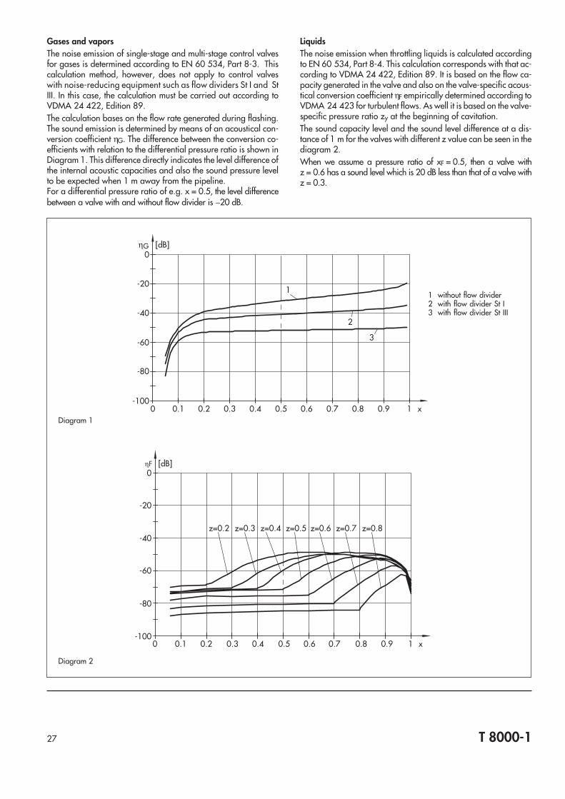
Gases and vaporsThe noise emission of single-stage and multi-stage control valvesfor gases is determined according to EN 60 534, Part 8-3. Thiscalculation method, however, does not apply to control valveswith noise-reducing equipment such as flow dividers St I and StIII. In this case, the calculation must be carried out according toVDMA 24 422, Edition 89.The calculation bases on the flow rate generated during flashing.The sound emission is determined by means of an acoustical con-version coefficient ηG. The difference between the conversion co-efficients with relation to the differential pressure ratio is shown inDiagram 1. This difference directly indicates the level difference ofthe internal acoustic capacities and also the sound pressure levelto be expected when 1 m away from the pipeline.For a differential pressure ratio of e.g. x = 0.5, the level differencebetween a valve with and without flow divider is −20 dB.
LiquidsThe noise emission when throttling liquids is calculated accordingto EN 60 534, Part 8-4. This calculation corresponds with that ac-cording to VDMA 24 422, Edition 89. It is based on the flow ca-pacity generated in the valve and also on the valve-specific acous-tical conversion coefficient ηF empirically determined according toVDMA 24 423 for turbulent flows. As well it is based on the valve-specific pressure ratio zy at the beginning of cavitation.The sound capacity level and the sound level difference at a dis-tance of 1 m for the valves with different z value can be seen in thediagram 2.When we assume a pressure ratio of xF = 0.5, then a valve withz = 0.6 has a sound level which is 20 dB less than that of a valve withz = 0.3.
0 0.1 0.2 0.3 0.4 0.5 0.6 0.7 0.8 0.9 1 x
0
-20
-40
-60
-80
-100
[dB]ηF
z=0.2 z=0.3 z=0.4 z=0.5 z=0.6 z=0.7 z=0.8
Diagram 2
1
2
3
0 0.1 0.2 0.3 0.4 0.5 0.6 0.7 0.8 0.9 1 x
0
-20
-40
-60
-80
-100
[dB]ηG
1 without flow divider2 with flow divider St I3 with flow divider St III
Diagram 1
27 T 8000-1

Materials according to ASTM and DINThe body materials mainly used and their temperature limits arelisted in the following Table.
The application limits of selected materials are included in the as-sociated pressure-temperature table.
T 8000-128
Table 11 · Materials
Material Casting Forging Temperature range
Identification Standard Grade Identification Standard Grade [°F] [°C]
Materials according to ASTM
Gray iron Cast iron ASTM A 126 Class B – – – –20 ... +450 –29 ... +232
Ductile iron Ductile iron ASTM A 395 – – – – –20 ... +650 –29 ... +343
Aluminum Bronze UNS C95200 ASTM B 148 9A – – – –20 ... +430 –29 ... +220
Carbon steel WCB ASTM A 216 WCB – ASTM A 105 – –20 ... +800 –29 ... +427
Carbon steel, low temp. LCB ASTM A 352 LCB – ASTM A 350 LF 2 –50 ... +650 –46 ... +343
Carbon steel, low temp. 3½ Ni ASTM A 352 LC3 – ASTM A 350 LF 3 –150 ... +650 –100 ... +343
Carbon steel, high temp Chrome Moly ASTM A 217 WC6 UNS K11564 ASTM A 182 F 12 –20 ... +1100 –29 ... +593
Carbon steel, high temp Chrome Moly ASTM A 217 WC9 UNS K21590 ASTM A 182 F 22 –20 ... +1100 –29 ... +593
Stainless steel 18Cr-8Ni Type 304 ASTM A 351 CF8 UNS S30400 ASTM A 182 F 304 –425 ... +1000 –254 ... +537
Stainless steel Type 316 ASTM A 351 CF8M UNS S31600 ASTM A 182 F 316 –425 ... +1000 –254 ... +537
Stainless steel Type 316 L ASTM A 351 CF3M UNS S31603 ASTM A 182 F 316 L –425 ... +850 –254 ... +454
Alloy 400 Ni-Cu ASTM A 494 M35-1 UNS N04400 ASTM A 564 400 –20 ... +500 –29 ... +260
Alloy C-4 Ni-Mo-Cr ASTM A 494 CW2M UNS N06455 ASTM A 574 C-4 –20 ... +800 –29 ... +427
Comparable materials according to DIN
Gray cast iron GG-25 DIN 1691 0.6025 – – – +14 ... +572 –10 ... +300
Spheroidal graphite iron GGG-40.3 DIN 1693 0.7043 – – – +14 ... +662 –10 ... +350
Cast steel GS-C25 DIN 17 245 1.0619 C 22.8 DIN 17 243 1.0460 +14 ... +752 –10 ... +400
Cast steel, low temp. GS-21 Mn 5 SEW 685 1.1138 TStE 355 SEW 081 1.0566 –58 ... +572 –50 ... +300
Cast steel, high temp. GS-17CrMo 5 5 DIN 17 245 1.735713CrMo 44 1.7335
+14 ... +932 –10 ... +500
Cast steel, high temp. GS-17CrMo V 5 11 DIN 17 245 1.7706 +14 ... +1022 –10 ... +550
Stainless steel G-X6CrNi 18 9 DIN 17 445 1.4308 X5CrNi 18 9 1.4301 –328 ... +572 –200 ... +300
Stainless steel (cast) G-X5CrNiMoNb18 10 DIN 17 445 1.4581 – – – +14 ... +842 –10 ... +450
Stainless steel (forged) – – – X6 CrNiMoTi17 12 2 DIN 17 440 1.4571 –454 ... +842 –270 ... +450
Stainless steel (forged) – – – X2 CrNiMo17 12 2 DIN 17 440 1.4404 –454 ... +842 –270 ... +450
Alloy 400 NiCu30Fe DIN 17743 2.4360 2.4360
Alloy C4-C NiMo16Cr16Ti DIN 17744 2.4610 2.4610 +14 ... +752 –10 ... +400

29 T 8000-1
Table 12 ⋅ Permissible pressure dependent upon the temperature ⋅ Iron and Bronze acc. to ANSI B16.1, B16.4, B16.15, B16.24
Body material ClassTemperature (°F) and perm. operating pressure (psi)
–20 100 150 175 200 225 250 275 300 325 350 353 375 400 406 425 450
Threaded (NPT)
A 126 Cl.B (NPT)B16.4 –20...406 °F
125 175 (175) 175 (170) 165 (158) 150 (145) 140 (133) 125 125 – – –
250 400 (400) 400 (385) 370 (355) 340 (325) 310 (305) 300 (297) (275) 250 250
B 62 Bronze (NPT)B16.15 –20...400 °F
125 200 (200) 200 (195) 190 (185) 180 (173) 165 (158) 150 (149) (138) 125
250 400 (400) 400 (393) 385 (375) 365 (350) 335 (318) 300 (297) (275) 250
Flat face flanged (FF)
A 126 Cl.B (FF)B16.1 –20...450 °F
125 200 (200) 200 (195) 190 180 175 170 165 155 (150) 150 145 (141) 140 130 125
250 500 (500) 500 (480) 460 440 415 395 375 355 (337) 335 315 (295) 290 270 250
B 62 Bronze (FF)B16.24 –20...430 °F
150 225 (225) 225 220 210 205 195 190 180 (173 165 (164) (158) (152) 150 135 –
300 500 (500) 500 480 465 445 425 410 390 (390) 350 (348) (333) (315) (311) (298) 280
Table 12b ⋅ Permissible pressure dependent upon the temperature ⋅ Steels according to ANSI B16.34 ⋅ Standard Class
Body material ClassTemperature (°F) and perm. operating pressure (psi)
–20 100 200 300 400 500 600 650 700 750 800 850 900 950 1000 1050 1100
A 216 WCB–20 ... +800 °F
150 285 285 260 230 200 170 140 125 110 95 80
300 740 740 675 655 635 600 550 535 535 505 410
600 1480 1480 1350 1315 1270 1200 1095 1075 1065 1010 825
900 2220 2220 2025 1970 1900 1795 1640 1610 1600 1510 1235
1500 3705 3705 3375 3280 3170 2995 2735 2685 2665 2520 2060
2500 6170 6170 5625 5470 5280 4990 4560 4475 4440 4200 3430
A 105 forged–20 ... +800 °F 300 740 740 675 655 635 600 550 535 535 505 410
A 352 LCB–50 ... +650 °F
150 265 265 250 230 200 170 140 125
300 695 695 655 640 620 858 535 525
A 217 WC6–20 ... +1100 °F
300 750 750 710 675 660 640 605 590 570 530 510 485 450 380 225 140 95
600 1500 1500 1425 1345 1315 1285 1210 1175 1135 1065 1015 975 900 755 445 275 190
900 2250 2250 2135 2020 1975 1925 1815 1765 1705 1595 1525 1460 1350 1130 670 410 290
1500 3750 3750 3560 3365 3290 3210 3025 2940 2840 2660 2540 2435 2245 1885 1115 684 480
2500 6250 6250 5930 5605 5485 5350 5040 4905 4730 4430 4230 4060 3745 3145 1860 1145 800
A 217 WC9–20 ... +1100 °F
300 750 750 715 675 650 640 605 590 570 530 510 485 450 380 270 200 115
600 1500 1500 1430 1355 1295 1280 1210 1175 1135 1065 1015 975 900 755 535 400 225
900 2250 2250 2150 2030 1945 1920 1815 1765 1705 1595 1525 1460 1350 1130 805 595 340
1500 3750 3750 3580 3385 3240 3200 3025 2940 2840 2660 2540 2435 2245 1885 1340 995 565
2500 6250 6250 5965 5640 5400 5330 5040 4905 4730 4430 4230 4060 3745 3145 2230 1660 945
A 351 CF8–425 ... +1500 °F 2)
150 275 275 235 205 180 170 140 125 110 95 80 65 50 35 20
300 720 720 600 530 470 435 415 410 405 400 395 390 385 375 325
600 1440 1440 1200 1055 940 875 830 815 805 795 790 780 770 750 645
900 2160 2160 1800 1585 1410 1310 1245 1225 1210 1195 1180 1165 1150 1125 965
A 351 CF8M–425 ... +1500 °F 2)
A 351 CF3M–425 ... +850 °F
150 275 275 240 215 195 170 140 125 110 95 80 65 50 35 20
300 720 720 620 560 515 480 450 445 430 425 415 405 395 385 365
600 1440 1440 1240 1120 1030 955 905 890 865 845 830 810 790 775 725
900 2160 2160 1860 1680 1540 1435 1355 1330 1295 1270 1245 1215 1180 1160 1090
1500 3600 3600 3095 2795 2570 2390 2255 2220 2160 2110 2075 2030 1970 1930 1820
2500 6000 6000 5160 4660 4280 3980 3760 3700 3600 3520 3460 3380 3280 3220 3030
A 182 F 316 forged–425 ... +1500 °F 2) 300 720 720 620 560 515 480 450 445 430 425 415 405 395 385 365
Values in parentheses are interpolated values.Some valve types may have lower limits based on the design. Consult the Technical Data Sheet for the respective model.1) For welding end valves only. Flanged end valves terminate at 1000 °F.2) For temperatures above 1000 °F, use only when carbon is 0.04% or higher. For temperature values above 1100 °F, consult the ANSI standard.
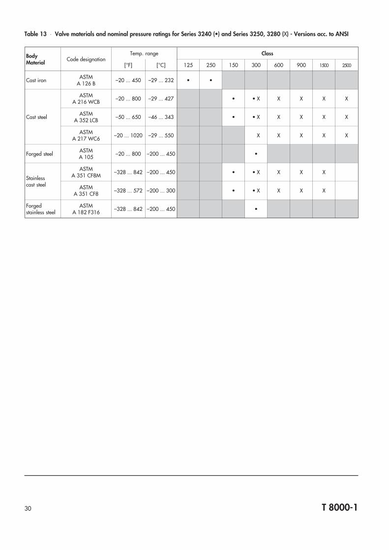
T 8000-130
Table 13 ⋅ Valve materials and nominal pressure ratings for Series 3240 (•) and Series 3250, 3280 (X) - Versions acc. to ANSI
BodyMaterial
Code designationTemp. range Class
[°F] [°C] 125 250 150 300 600 900 1500 2500
Cast iron ASTMA 126 B –20 ... 450 –29 ... 232 • •
Cast steel
ASTMA 216 WCB –20 ... 800 –29 ... 427 • • X X X X X
ASTMA 352 LCB –50 ... 650 –46 ... 343 • • X X X X X
ASTMA 217 WC6 –20 ... 1020 –29 ... 550 X X X X X
Forged steel ASTMA 105 –20 ... 800 –200 ... 450 •
Stainlesscast steel
ASTMA 351 CF8M –328 ... 842 –200 ... 450 • • X X X X
ASTMA 351 CF8 –328 ... 572 –200 ... 300 • • X X X X
Forgedstainless steel
ASTMA 182 F316 –328 ... 842 –200 ... 450 •

Selection and Ordering informationSelection and sizing of the control valve1. Calculate the required CV or KV value according to ISA-
S75.01 or EN 60534. You may use for example the SAMSONprogram “Valve sizing”. This sizing usually is also carried outby SAMSON. If real operating data are used for the calcula-tion, apply the following equation:CVmax ≈ 0.7 to 0.8 · CVrated or KVmax ≈ 0.7 to 0.8 · KVS
2. Select the CVrated or KVS value and the nominal size DN ac-cording to the table in the corresponding Data Sheet.
3. Select the appropriate characteristic curve on the basis of thebehaviour of the controlled system.
4. Determine the permissible differential pressure ∆p and selectan adequate actuator using the differential pressure tables in-cluded in the associated Technical Data Sheet.
5. Select the materials to be used with regard to corrosion, ero-sion, pressure and temperature. Please use the materials tablesand the associated pressure-temperature diagram.
6. Select the additional equipment, such as positioners and/orlimit switches.
Ordering informationPlease submit the following details in your order:
Type of control valve: . . . 1)
Nominal size ANSI or DN: . . . 1)
Nominal pressure ANSI or PN: . . . 1)
Body material: . . . 1)
Connecting type: Flanged connection/welding ends/socket welded ends
Plug 1): Standard, pressure-balanced,with metal sealing, soft sealing, orlapped-in metal plughard facing, if needed
Characteristic : Equal percentage or linear
Pneumat. actuator: Versions acc. to T 8310 or T 8311Fail-safe action: Valve closed or openActuating time: (please submit this detail only if
special actuating times are required)Process medium: Density in kg/m3
under standard or operating conditions,and temperature in°F, °C
Flow rate: In kg/h or m3/hunder standard or operating conditions
Pressure: p1 in bar (absolute pressure pabs)p2 in bar (absolute pressure pabs)for min., standard and max. flow rate
Accessories: Positioner and/or limit switch,position transmitter, solenoid valve,lock-up valve, volume amplifier,supply pressure regulator
1) If no details have been submitted, SAMSON will make aproposal
31 T 8000-1
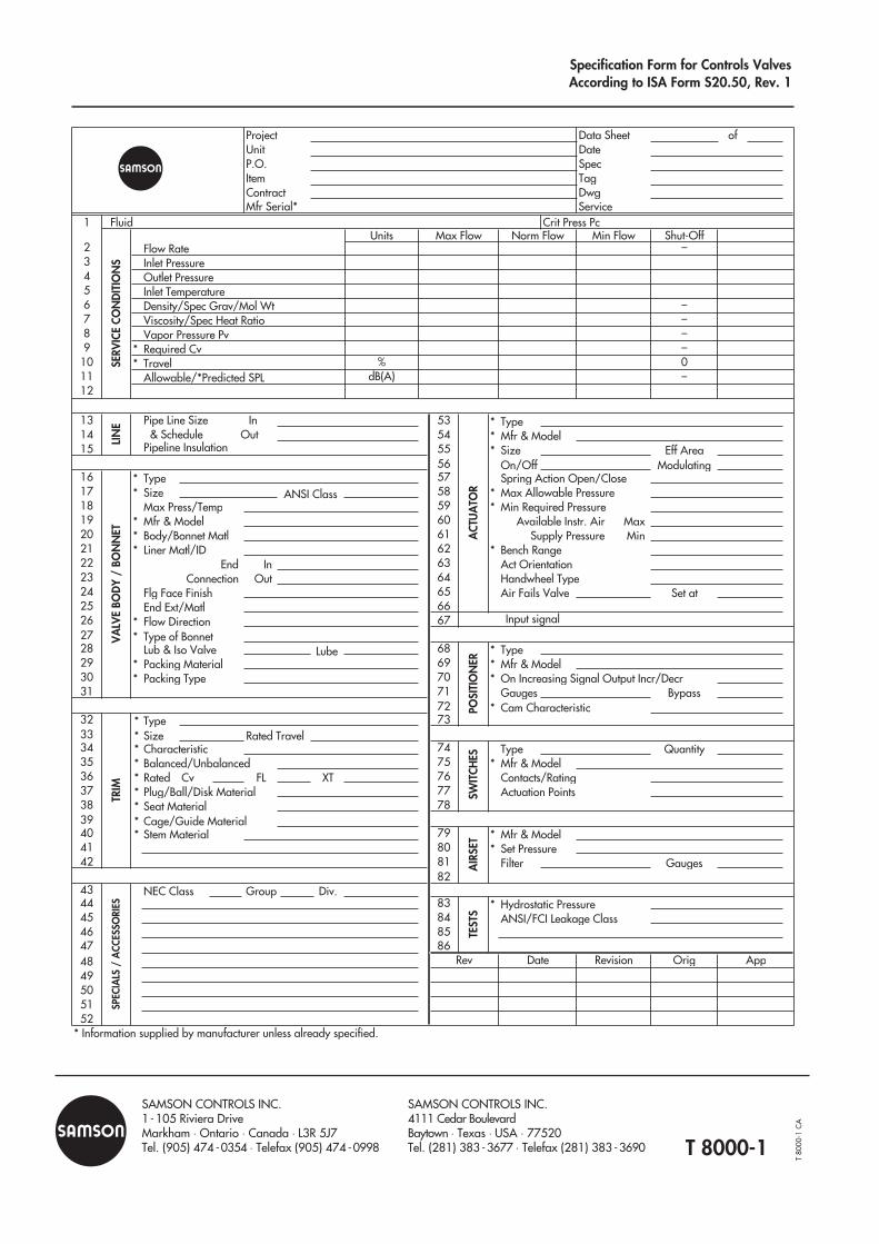
T 8000-1
SAMSON CONTROLS INC.1- 105 Riviera DriveMarkham ⋅ Ontario ⋅ Canada ⋅ L3R 5J7Tel. (905) 474 -0354 ⋅ Telefax (905) 474 -0998
SAMSON CONTROLS INC.4111 Cedar BoulevardBaytown ⋅ Texas ⋅ USA ⋅ 77520Tel. (281) 383 -3677 ⋅ Telefax (281) 383 -3690
Specification Form for Controls ValvesAccording to ISA Form S20.50, Rev. 1
Project Data Sheet ofUnit DateP.O. SpecItem TagContract DwgMfr Serial* Service
1 FluidUnits Min Flow Shut-Off
2 Flow Rate –3 Inlet Pressure4 Outlet Pressure5 Inlet Temperature6 Density/Spec Grav/Mol Wt –7 Viscosity/Spec Heat Ratio –8 Vapor Pressure Pv –9 * Required Cv –
10 * Travel % 011 Allowable/*Predicted SPL dB(A) –12
13 Pipe Line Size In 53 * Type14 & Schedule Out 54 * Mfr & Model15 Pipeline Insulation 55 * Size Eff Area
56 On/Off Modulating16 * Type 57 Spring Action Open/Close17 * Size ANSI Class 58 * Max Allowable Pressure18 Max Press/Temp 59 * Min Required Pressure19 * Mfr & Model 6020 * Body/Bonnet Matl 6121 * Liner Matl/ID 62 * Bench Range22 63 Act Orientation23 64 Handwheel Type24 Flg Face Finish 65 Air Fails Valve Set at25 End Ext/Matl 6626 * Flow Direction 6727 * Type of Bonnet28 Lub & Iso Valve Lube 68 * Type29 * Packing Material 69 * Mfr & Model30 * Packing Type 70 *31 71 Gauges Bypass
72 * Cam Characteristic32 * Type 7333 * Size Rated Travel34 * Characteristic 74 Type Quantity35 * Balanced/Unbalanced 75 * Mfr & Model36 * Rated Cv FL XT 76 Contacts/Rating37 * Plug/Ball/Disk Material 77 Actuation Points38 * Seat Material 7839 * Cage/Guide Material40 * Stem Material 79 * Mfr & Model41 80 * Set Pressure42 81 Filter Gauges
8243 Group Div.44 83 * Hydrostatic Pressure45 84 ANSI/FCI Leakage Class46 8547 8648 Revision Orig49505152
* Information supplied by manufacturer unless already specified.
Date
End In Connection Out
Available Instr. Air Max Supply Pressure Min
SERV
ICE
CON
DIT
ION
S
ACT
UA
TOR
LIN
EV
ALV
E BO
DY
/ BO
NN
ET
POSI
TIO
NER
TRIM
Max Flow
SW
ITCH
ES
Rev
SPEC
IALS
/ A
CCES
SORI
ES
TEST
SA
IRSE
T
NEC Class
Norm Flow
On Increasing Signal Output Incr/Decr
Input signal
Crit Press Pc
App
T80
00-1
CA
Related Documents
![INDEX PVC-U BALL VALVES BALL VALVES … · 135 ball valves vÁlvulas de bola 01 industrial series [std] series standard series connectit system e-qua series pn10 series uniblock series](https://static.cupdf.com/doc/110x72/5bb23b8209d3f2e82b8c356e/index-pvc-u-ball-valves-ball-valves-135-ball-valves-valvulas-de-bola-01-industrial.jpg)