Corresponding author : A. Chbeb Unité de recherche en CSSS, Ecole Supérieure des Sciences et Techniques de Tunis (ESSTT), Tunis – Tunisia [email protected], Copyright © JES 2009 on-line : journal.esrgroups.org/jes A. Chbeb M. Jemli M. Boussak O. Khlaief M. Gossa J. Electrical Systems x-x (xxx): x-xx Regular paper Sensorless Speed Control of Permanent Magnet Synchronous Motor Drive Using Extended Kalman Filter With Initial Rotor Position Estimation This paper proposes a new approach to a sensorless speed control and an initial rotor position estimation a salient pole Permanent Magnet Synchronous Motor (PMSM) drive. The estimation of the position and of the speed in dynamic rate were derived by the use of the extend Kalman filter algorithm by only measuring the phase voltages and motor currents. For the starting with a maximum torque and an imposed rotation way, it is necessary to know the initial position. The starting procedure is a problem under sensorless drives, because no information is available before starting. In this work, we shall establish a new convenient technique for detecting the rotor initial position, based on signal tests applied to the stopped machine. The validity of the proposed sensorless control strategy, according to the different initial rotor position conditions are discussed and simulation results are presented. The experimental results show very well the validity of the proposed method for the estimation of the initial rotor position of the PMSM. Keywords: Permanent Magnets Synchronous Machine (PMSM), vector control, Extended Kalman Filter (EKF), sensorless drive, initial position estimation. 1. Nomenclature d, q Two-axis synchronous frame quantities. α, β Two-axis stationary frame quantities. v d , v q d- and q-axis components of stator voltage on rotating frame. i d , i q d- and q-axis stator current on rotating frame. n p Number of pole pairs. R s Armature winding resistance. L d , L q d- and q-axis stator self inductances. l s Leakage inductance. L 0 Component of the self inductance due to space fundamental air-gap flux. L 2 Component of the self inductance due to rotor position dependent flux. f Φ ˆ Inductor flux created by the magnets, p Differential operator. ω Rotor speed at electrical angle. θ Rotor position at electrical angle. J Rotor inertia. F Frictional constant. T e Electromagnetic torque. T r Load torque. K e EMF constant. K t Torque constant. u Control matrix.

Welcome message from author
This document is posted to help you gain knowledge. Please leave a comment to let me know what you think about it! Share it to your friends and learn new things together.
Transcript

Corresponding author : A. Chbeb Unité de recherche en CSSS, Ecole Supérieure des Sciences et Techniques de Tunis (ESSTT), Tunis – Tunisia [email protected], Copyright © JES 2009 on-line : journal.esrgroups.org/jes
A. Chbeb M. Jemli M. Boussak O. Khlaief M. Gossa
J. Electrical Systems x-x (xxx): x-xx
Regular paper
Sensorless Speed Control of Permanent Magnet Synchronous
Motor Drive Using Extended Kalman Filter With Initial Rotor Position
Estimation
This paper proposes a new approach to a sensorless speed control and an initial rotor position estimation a salient pole Permanent Magnet Synchronous Motor (PMSM) drive. The estimation of the position and of the speed in dynamic rate were derived by the use of the extend Kalman filter algorithm by only measuring the phase voltages and motor currents. For the starting with a maximum torque and an imposed rotation way, it is necessary to know the initial position. The starting procedure is a problem under sensorless drives, because no information is available before starting. In this work, we shall establish a new convenient technique for detecting the rotor initial position, based on signal tests applied to the stopped machine. The validity of the proposed sensorless control strategy, according to the different initial rotor position conditions are discussed and simulation results are presented. The experimental results show very well the validity of the proposed method for the estimation of the initial rotor position of the PMSM.
Keywords: Permanent Magnets Synchronous Machine (PMSM), vector control, Extended Kalman Filter (EKF), sensorless drive, initial position estimation.
1. Nomenclature
d, q Two-axis synchronous frame quantities. α, β Two-axis stationary frame quantities. vd, vq d- and q-axis components of stator voltage on rotating frame. id, iq d- and q-axis stator current on rotating frame. np Number of pole pairs. Rs Armature winding resistance. Ld, Lq d- and q-axis stator self inductances. ls Leakage inductance. L0 Component of the self inductance due to space fundamental air-gap flux. L2 Component of the self inductance due to rotor position dependent flux.
fΦ̂ Inductor flux created by the magnets, p Differential operator. ω Rotor speed at electrical angle. θ Rotor position at electrical angle. J Rotor inertia. F Frictional constant. Te Electromagnetic torque. Tr Load torque. Ke EMF constant. Kt Torque constant. u Control matrix.
2
f(x) System state matrix. F Partial derivative system matrix. H Output matrix. K Kalman filter gain matrix. P State covariance matrix. Q System noise covariance matrix. R Measurement noise covariance matrix. G Weighting matrix of noise. w(k) state noise vector v(k) measure noise vector.
RLd
d =τ d axis time constant; RLq
q =τ q axis time constant.
2. Introduction
In recent years, there has been an emerging growth of PMSM. This machine has been widely used in many industrial applications. The main advantages, as compared with other ac motor drive, are high power factor, high power density, high torque to current ratio, large power to weight ratio, high efficiency; Hence robustness, lower loss, lower maintenance and less complex motor can be obtained [1-7].
However, in case of traditional PMSM points of brutal variation of the load torque of the feeding frequency can always be the origin of dislocations phenomena. To resolve this problem, the stator current must be commuted in synchronism with the rotor position. This is possible if we use a position sensor which informs a control system leading to command the PWM inverter switches: such method is called self driving.
The whole PMSM fed by a PWM inverter constitutes a non linear system which is relatively difficult to control by the linear commands. Moreover the PWM inverter transistors only need discrete command signals. Consequently it would be more convenient to use for the PMSM a non linear command system based on the two level regulation technique.
In recent years many models have been made in the study of synchronous static machine converter. A typical approach has been based on the PMSM vector control.
The PMSM vector command needs a precise knowledge of the rotor position which ensures the machine self driving. This knowledge can be directly obtained by a position sensor or indirectly by a speed sensor.
The drawbacks of the mechanical sensor use, placed on the machine shaft are numerous [8-10]. First, the mechanical sensor presence increases the volume and the global system cost. Then it requires an available shaft end which can constitute a drawback for small-sized machines. Moreover, the installation of this sensor requires a chock relating to the stator, operation which proves to be delicate and decreases the reliability of the system.
In view of these limitations that introduce the machine function with mechanical sensor, various studies have been made to suppress that mechanical sensor while preserving the best performances of the machine [11-18]. These studies have investigated different methods of the vector control without sensor. They are all based on the use of some electrical variable currents and voltages, to estimate the rotor position according to a representative model of the machine.
The Kalman filter leads to achieve a maximum observation of the machine state, its programming on calculator is easy as the state of the permanent magnet synchronous
3
machine is well known. The variation of the machine electrical parameters can be taken into account in the Kalman filter algorithm, which leads to minimize, the error on the state estimation. The measured currents and voltages are transformed in the Clarcke referential and are applied to the state space model. The speed and position are estimated using the Kalman filter algorithm.
3. State SPACE Model of the Permanent Magnets Synchronous Machine
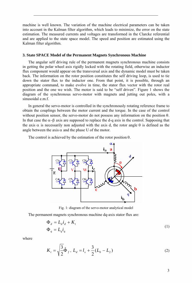
The angular self driving rule of the permanent magnets synchronous machine consists in getting the polar wheel axis rigidly locked with the rotating field, otherwise an inductor flux component would appear on the transversal axis and the dynamic model must be taken back. The information on the rotor position constitutes the self driving loop, is used to tie down the stator flux to the inductor one. From that point, it is possible, through an appropriate command, to make evolve in time, the stator flux vector with the rotor real position and the one we wish. The motor is said to be “self driven”. Figure 1 shows the diagram of the synchronous servo-motor with magnets and jutting out poles, with a sinusoidal e.m.f.
In general the servo-motor is controlled in the synchronously rotating reference frame to obtain the couplings between the motor current and the torque. In the case of the control without position sensor, the servo-motor do not possess any information on the position θ. In that case the α−β axis are supposed to replace the d-q axis in the control. Supposing that the axis α is necessarily non adjusted with the axis d, the rotor angle θ is defined as the angle between the axis α and the phase U of the motor.
The control is achieved by the estimation of the rotor position θ.
Fig. 1: diagram of the servo-motor analytical model
The permanent magnets synchronous machine dq-axis stator flux are:
qqq
tddd
iLKiL
=+=
ΦΦ
(1)
where
ftK Φ̂23
= , )(23
20 LLlL sd −+= (2)
4
)(23
20 LLlL sq ++=
The electrical equations of the machine in the axis d,q are represented by the following systems:
⎥⎦
⎤⎢⎣
⎡+⎥
⎦
⎤⎢⎣
⎡
⎥⎥⎦
⎤
⎢⎢⎣
⎡
+
−+=⎥
⎦
⎤⎢⎣
⎡ωω
ω
0
.. .
. .
tq
d
qd
qd
q
d
KII
pLRL
LpLRVV
(3)
The electromagnetic torque:
)ΦΦ( dqqdpe iinC −= (4)
where pn is the number of pole pairs.
This finally gives:
[ ]qtqdqdpe iKiiLLnC +−= )( (5)
The mechanical equation is given by the following relation:
re TTfdtdJ −=Ω+Ω (6)
Setting id to zero in expression (5), the electromagnetic torque becomes proportional to the axis component q of the stator current, and hence the current iq is chosen as the main adjustment scale.
The corresponding electromagnetic torque becomes:
qtpe iKnC = (7)
This is an expression similar to a direct current machine. The state model of the permanent magnets synchronous machine is represented by the following non linear fourth order system:
0 0 0
0 0
0 1 0
0 0 1
0 1 0 0
0 n
0 1
0 0 1
22⎥⎥⎥
⎦
⎤
⎢⎢⎢
⎣
⎡
⎥⎥⎥⎥⎥⎥⎥⎥⎥
⎦
⎤
⎢⎢⎢⎢⎢⎢⎢⎢⎢
⎣
⎡
−
−
+
⎥⎥⎥⎥⎥
⎦
⎤
⎢⎢⎢⎢⎢
⎣
⎡
⎥⎥⎥⎥⎥⎥⎥⎥⎥
⎦
⎤
⎢⎢⎢⎢⎢⎢⎢⎢⎢
⎣
⎡
−−
−−−
−
=
⎥⎥⎥⎥⎥⎥⎥⎥⎥⎥
⎦
⎤
⎢⎢⎢⎢⎢⎢⎢⎢⎢⎢
⎣
⎡
r
q
d
p
d
d
q
d
tp
qdp
q
e
dq
d
q
d
d
q
d
T
vv
Jn
L
L
ii
Jf
JK
JLL
n
LK
LL
LL
dtddtddtdidtdi
θω
τω
ωτ
θ
ω (8)
4. The Vector Control
The vector control needs that the current iq be either in quadrature as far as the rotor flux is concerned. In consequence the current id must be co-linear to the rotor flux. By
5
specifying a particular value of the current id, say id=0, the electromagnetic torque becomes proportional to the stator current iq and as a consequence it becomes the main parameter of adjustment.
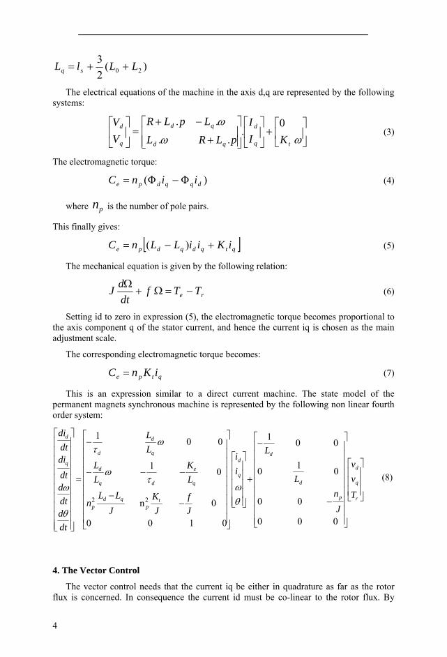
The synchronous motor model becomes similar to a DC motor.
-
-KI
Ω θq IqRq Lq+ p
1Tr
Te
++
KI
K+J p1 1
p
Fig. 2: reduced model of the permanent magnet synchronous motor
Maintaining the same value of the current (id =0), allows to obtain for a certain amplitude of stator currents, the maximum of the relation torque/current. To control the speed and/or the position we act on the current iq, that is to say on the torque developed by the motor.
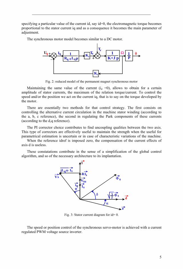
There are essentially two methods for that control strategy. The first consists on controlling the alternative current circulation in the machine stator winding (according to the a, b, c reference), the second in regulating the Park components of these currents (according to the d,q reference).
The PI corrector choice contributes to find uncoupling qualities between the two axis. This type of correctors are effectively useful to maintain the strength when the useful for parametrical estimation is uncertain or in case of characteristic variations of the machine. When the reference idref is imposed zero, the compensation of the current effects of axis d is useless.
These constatations contribute in the sense of a simplification of the global control algorithm, and so of the necessary architecture to its implantation.
a
dα
δ
ϕ
Φ
Φ32
I
V
RIjLq ω I
Vs
i
s
ss
sq
s
s0
Fig. 3: Stator current diagram for id= 0.
The speed or position control of the synchronous servo-motor is achieved with a current regulated PWM voltage source inverter.
6
5. Extented Kalman Filter Algorithm
The Kalman filter is a mathematical tool able to determine system parameters and to observe states from measurable voltages and currents [19-22].
That filter is built on certain hypotheses, especially on the noises. It supposes that the noises which affect the model are centered and white, and that they are uncorrelative of the estimated states. Moreover the state noises must be uncorrelative of the measure noises.
As the following stochastic non linear model:
⎩⎨⎧
+=+=+
)())(()()())(),(()1(
kvkxhkYkwkUkxfkx
(9)
We change this non linear system to a linear system and deduce from it the EKF equation set.
The estimation procedure is split in two steps:
– a prediction step,
– a correction step.
Prediction step Estimation under the prediction form:
)().()/(ˆ).()/)1((ˆ kUkGkkxkFkkx +=+ (10)
with
{ } )(),(ˆ),(),(()( kUkxkkUkxfx
kF∂∂
= (11)
{ } )(),(ˆ),(),(()( kUkxkkUkxfU
kG∂∂
= (12)
This step led to build a first estimation of the state vector at the moment k+1. We try to determine its variant: Covariant matrix of the prediction error:
QkFkkPkFkkP T +=+ )()./().()/)1(( (13)
Correction step The phase of prediction allows to have a gap between the measured exit )1( +kY and
the predicted exit )1(ˆ +kY . To improve the state it is necessary to minimize this variation and correct it by the intermediary of the filter gain.
Kalman filter gain
( ) 1)()/)1(()().1()./)1(()1( −++++=+ RkHkkPkHkHkkPkK TT (14)
with
( ))(ˆ)()(
)( )( kxkxkxkxhkH =∂
∂= (15)
Covariant matrix of the filter error:
7
)/)1(()1()1()/)1(())1/()1(( kkPkHkKkkPkkP +++−+=++ (16)
Estimation of the state vector at the moment k+1:
( ))/)1((ˆ)1()1()1()/)1((ˆ))1/()1((ˆ
kkxkHkYkKkkxkkx
++−++++=++
(17)
The extended Kalman filter algorithm is very complex. Effectively it is difficult to implant these matrix operations by using Matlab/Simulink.
For the simulation, this algorithm is implanted as a system function “S-function” then it is inserted in the global simulation system diagram.
6. Sensorless Control with EKF
The control without mechanical sensor uses the machine stator phase currents and voltages, to reconstitute the non accessible parameters (speed, position) with the EKF help. The permanent magnets synchronous machine model in αβ reference frame is given by:
⎥⎥⎥
⎦
⎤
⎢⎢⎢
⎣
⎡−+
⎥⎥⎥⎥
⎦
⎤
⎢⎢⎢⎢
⎣
⎡
⎥⎥⎥⎥
⎦
⎤
⎢⎢⎢⎢
⎣
⎡
−
++
⎥⎥⎥
⎦
⎤
⎢⎢⎢
⎣
⎡
⎥⎥⎥
⎦
⎤
⎢⎢⎢
⎣
⎡
+
−=
⎥⎥⎥
⎦
⎤
⎢⎢⎢
⎣
⎡
θω
θω
θθ
θθ
θωθω
θωθω
β
α
β
α
β
α
sin
sin
2cos22
2sin2
2sin2
2cos22
2sin 2cos
2cos 2sin
t
t
t
t
DSD
DDS
SsS
SSs
K
K
didididi
LLL
LLL
i
i
LRL
LLR
v
v
(18)
With: qdS LLL += ; qdD LLL −= ; qd LLL .=Π
The electromagnetic torque in the stationary reference frame α, β is: [ ]
( )[ ]⎪⎭⎪⎬⎫
⎪⎩
⎪⎨⎧
+−
+−=
θθ
θθ
βααβ
αβ
2cos22sin21
)sincos(
22 iiiiL
iiKNC
D
t
pe (19)
The state equation (20) is the PMSM model in the reference frame αβ. The control structure is presented in figure4.
(20)
This state model will be used for rotor position estimation in dynamic torque by the extended Kalman filter algorithm. The control structure is presented in figure 4.
0 0
0 )2cos(2
1 2sin2
0 2sin2
)2cos(2
1
0 1 0 0
0 )2cos22sin(2
cos 2sin2
sin
0 sin 2sin2
)2cos(2
2sin2
)2cos(2
0 sin 2sin2
)2cos(2
2sin2
)2cos(2
22
⎥⎥⎥
⎦
⎤
⎢⎢⎢
⎣
⎡
⎥⎥⎥⎥⎥⎥⎥
⎦
⎤
⎢⎢⎢⎢⎢⎢⎢
⎣
⎡
−
+−
−−
+
⎥⎥⎥⎥⎥
⎦
⎤
⎢⎢⎢⎢⎢
⎣
⎡
⎢⎢⎢⎢⎢⎢⎢⎢⎢⎢
⎣
⎡
⎥⎥⎥⎥⎥⎥⎥⎥⎥
⎦
⎤
−⎥⎦⎤
⎢⎣⎡ ++⎟
⎠⎞
⎜⎝⎛ +−
−−−++−
+−+−−
=
⎥⎥⎥⎥⎥⎥⎥⎥⎥
⎦
⎤
⎢⎢⎢⎢⎢⎢⎢⎢⎢
⎣
⎡
ΔΣΔ
ΣΔΣ
ΔΔ
ΔΣ
ΔΣΔΣΔΔ
ΔΣΔΔ
ΔΣ
ΔΣ
ΠΠ
ΠΠ
ΠΠΠΠ
ΠΠΠΠ
rp
tp
tp
q
tss
q
tss
Cvv
Jn
LLLL
L
LLLL
L
ii
JfiiLK
Jn
iLKJn
LKL
LLLL
LRL
LRLL
LL
LKL
LRLL
LLL
LLLL
LR
dtddtddtdidtdi
β
α
β
α
αβα
β
α
θθ
θθ
θω
θθθθθ
θθωθθθω
θθθωθωθ
θ
ω
8
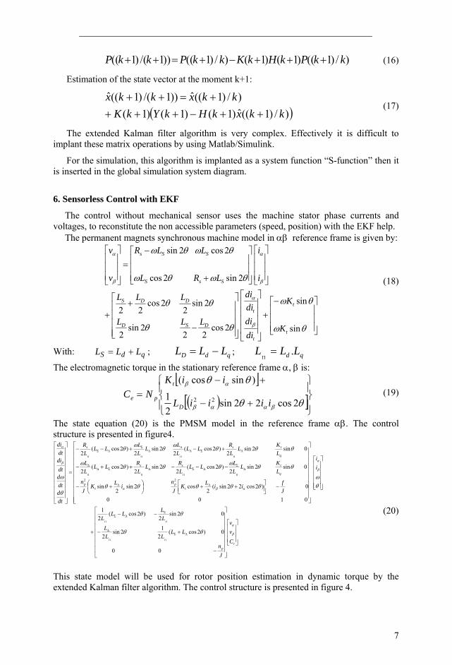
The inputs of the extended Kalman filter are the currents and the voltages. The outputs are the position and the rotor speed.
Fig. 4 : PMSM sensorless vector control
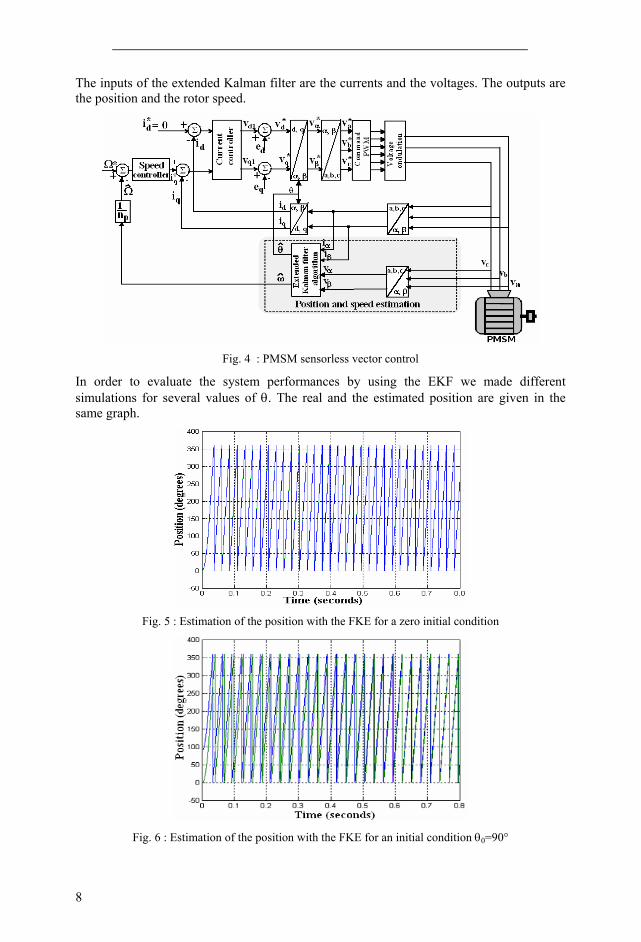
In order to evaluate the system performances by using the EKF we made different simulations for several values of θ. The real and the estimated position are given in the same graph.
Fig. 5 : Estimation of the position with the FKE for a zero initial condition
Fig. 6 : Estimation of the position with the FKE for an initial condition θ0=90°
9
We have concluded that the EKF allows us to estimate accurately the rotor position.
For an initial condition nil the estimation follows perfectly the real values from the starting point.
An incorrect initial rotor position may lead to a loss of decoupling between the magnet flux and stator flux, and a deterioration of the produced electromagnetic torque.
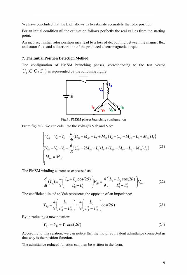
7. The Initial Position Detection Method
The configuration of PMSM branching phases, corresponding to the test vector )( 3211 CCCU is represented by the following figure:
Vaia
E
VbVcibic
Fig.7 : PMSM phases branching configuration
From figure 7, we can calculate the voltages Vab and Vac:
{ }
{ }
⎪⎪⎪
⎩
⎪⎪⎪
⎨
⎧
=
−−−++−=−=
+−−++−−=−=
caac
bcbcacabacacacaac
bbcbacaacbbacabaab
MM
IMLMLILMLdtdVVV
IMLMLIMLMLdtdVVV
)( )2(
)( )(
(21)
The PMSM winding current or expressed as:
( ) acaba VLL
LLVLL
LLIdtd )2cos(
94 )2cos(
94
22
20
2022
20
20⎟⎟⎠
⎞⎜⎜⎝
⎛−
+=⎟⎟
⎠
⎞⎜⎜⎝
⎛−
+=
θθ (22)
The coefficient linked to Vab represents the opposite of an impedance:
)2cos(94
94
22
20
222
20
0 θ⎟⎟⎠
⎞⎜⎜⎝
⎛
−+⎟⎟
⎠
⎞⎜⎜⎝
⎛
−=
LLL
LLL
Yéq (23)
By introducing a new notation:
)2cos(10 θYYYéq += (24)
According to this relation, we can notice that the motor equivalent admittance connected in that way is the position function.
The admittance reduced function can then be written in the form:
10
⎥⎦
⎤⎢⎣
⎡+== )2cos(1)(
0
1
0
θθYY
YY
N éq (25)
This function of period π has two relative extremes in θ=kπ/2. This involves difficulties to estimate the initial position with accuracy.
In transitory running, the peak value of the current depends on the rotor position. Moreover it exists a continuous component I0 corresponding to the admittance constant term.
A The Proposed Method Exploitation
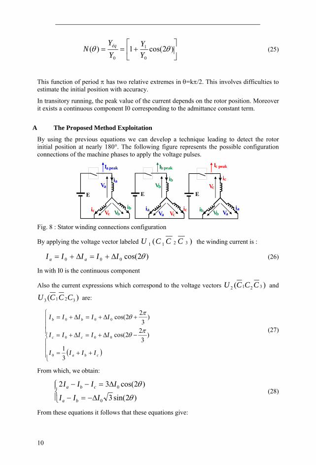
By using the previous equations we can develop a technique leading to detect the rotor initial position at nearly 180°. The following figure represents the possible configuration connections of the machine phases to apply the voltage pulses.
Vaia
Ia peak
E
Ib peak Ic peak
E E
ia iaVa Va
Vb
VbVb
ib
ib ib
ic
ic ic
Vc
Vc Vc Fig. 8 : Stator winding connections configuration
By applying the voltage vector labeled )( 3211 CCCU the winding current is :
)2cos(000 θIIIII aa Δ+=Δ+= (26)
In with I0 is the continuous component
Also the current expressions which correspond to the voltage vectors )( 3212 CCCU and
)( 3213 CCCU are:
( )⎪⎪⎪
⎩
⎪⎪⎪
⎨
⎧
++=
−Δ+=Δ+=
+Δ+=Δ+=
cba
cc
bb
IIII
IIIII
IIIII
31
)3
22cos(
)3
22cos(
0
000
000
πθ
πθ
(27)
From which, we obtain:
⎪⎩
⎪⎨⎧
Δ−=−
Δ=−−
)2sin(3
)2cos(32
0
0
θ
θ
III
IIII
ba
cba (28)
From these equations it follows that these equations give:
11
)2()(
3)2(
)(3
)2cos()2sin()2(
cba
ab
cba
ba
IIIII
IIIII
tg−−
−=
−−−
−==θθ
θ (29)
We can notice that this function is monotonous which allows us to replace the currents by
their increase aIΔ bIΔ cIΔ .
By approximating tg(2�) in the first order, we obtain the expression of the rotor angle in function of peak currents.
⎪⎪⎪
⎩
⎪⎪⎪
⎨
⎧
+Δ−Δ−Δ
Δ−Δ=
Δ−Δ−ΔΔ−Δ
=
πθ
θ
)2()(
321
)2()(
321
cba
ab
cba
ab
IIIII
orIII
II (30)
With
).2(21 θθ tg≅ (31)
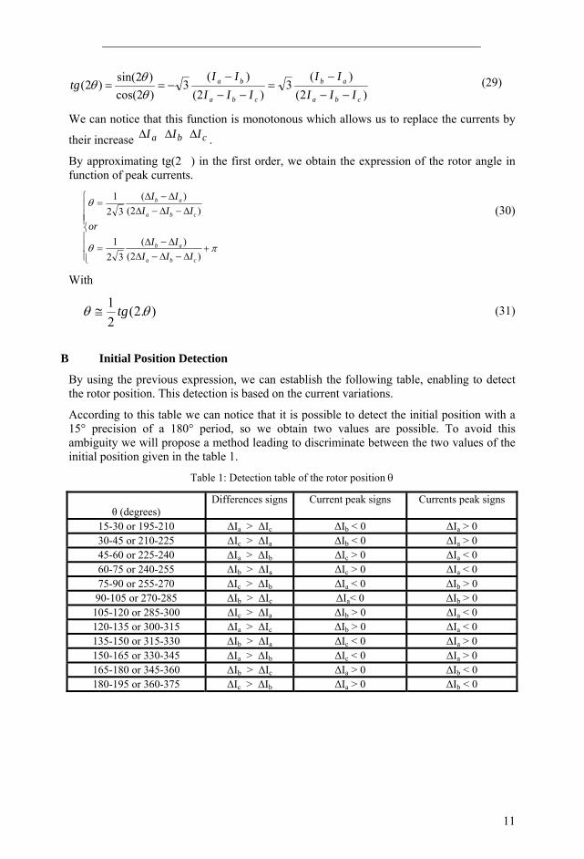
B Initial Position Detection
By using the previous expression, we can establish the following table, enabling to detect the rotor position. This detection is based on the current variations.
According to this table we can notice that it is possible to detect the initial position with a 15° precision of a 180° period, so we obtain two values are possible. To avoid this ambiguity we will propose a method leading to discriminate between the two values of the initial position given in the table 1.
Table 1: Detection table of the rotor position θ
θ (degrees)
Differences signs Current peak signs Currents peak signs
15-30 or 195-210 ΔIa > ΔIc ΔIb < 0 ΔIa > 0 30-45 or 210-225 ΔIc > ΔIa ΔIb < 0 ΔIa > 0 45-60 or 225-240 ΔIa > ΔIb ΔIc > 0 ΔIa < 0 60-75 or 240-255 ΔIb > ΔIa ΔIc > 0 ΔIa < 0 75-90 or 255-270 ΔIc > ΔIb ΔIa < 0 ΔIb > 0 90-105 or 270-285 ΔIb > ΔIc ΔIa< 0 ΔIb > 0
105-120 or 285-300 ΔIc > ΔIa ΔIb > 0 ΔIa < 0 120-135 or 300-315 ΔIa > ΔIc ΔIb > 0 ΔIa < 0 135-150 or 315-330 ΔIb > ΔIa ΔIc < 0 ΔIa > 0 150-165 or 330-345 ΔIa > ΔIb ΔIc < 0 ΔIa > 0 165-180 or 345-360 ΔIb > ΔIc ΔIa > 0 ΔIb < 0 180-195 or 360-375 ΔIc > ΔIb ΔIa > 0 ΔIb < 0
12
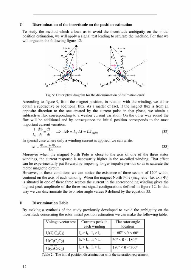
C Discrimination of the incertitude on the position estimation
To study the method which allows us to avoid the incertitude ambiguity on the initial position estimation, we will apply a signal test leading to saturate the machine. For that we will argue on the following figure 12.
Fig. 9: Descriptive diagram for the discrimination of estimation error.
According to figure 9, from the magnet position, in relation with the winding, we either obtain a subtractive or additional flux. As a matter of fact, if the magnet flux is from an opposite direction to the one created by the current pulse in that phase, we obtain a subtractive flux corresponding to a weaker current variation. On the other way round the flux will be additional and by consequence the initial position corresponds to the most important current variation.
dtdI
dtd
LS=
Φ1 ⇒ crêteILILS .. =Δ=ΔΦ (32)
In special case where only a winding current is applied, we can write.
Sstatoraim
LI Φ+Φ=Δ (33)
Moreover when the magnet North Pole is close to the axis of one of the three stator windings, the current response is necessarily higher in the so-called winding. That effect can be experimentally put forward by imposing longer impulse periods so as to saturate the motor magnetic circuit. However, in those conditions we can notice the existence of three sectors of 120° width, centered on the axis of each winding. When the magnet North Pole (magnetic flux axis Φf) is situated in one of these three sectors the current in the corresponding winding gives the highest peak amplitude of the three test signal configurations defined in figure 12. In that way we can discriminate the two rotor angle values θ defined by the equation 33.
D Discrimination Table
By making a synthesis of the study previously developed to avoid the ambiguity on the incertitude concerning the rotor initial position estimation we can make the following table.
Voltage vector test Currents peak in each winding
The rotor angle location
)CCC(U 321 Ia > Ib, Ia > Ic °− 60 < θ < 60°
)CCC(U 321 Ib > Ia, Ib > Ic 60° < θ < 180°°
)CCC(U 321 Ic > Ib, Ic > Ia 180° < θ < 300°
Table 2 : The initial position discrimination with the saturation experiment.
13
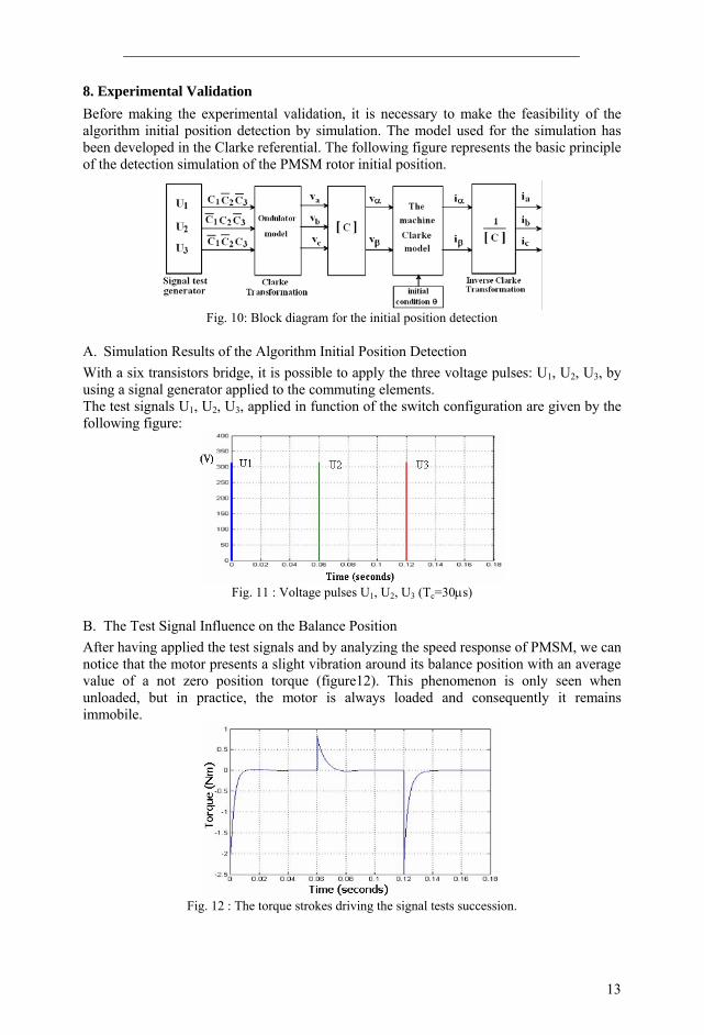
8. Experimental Validation Before making the experimental validation, it is necessary to make the feasibility of the algorithm initial position detection by simulation. The model used for the simulation has been developed in the Clarke referential. The following figure represents the basic principle of the detection simulation of the PMSM rotor initial position.
Fig. 10: Block diagram for the initial position detection
A. Simulation Results of the Algorithm Initial Position Detection With a six transistors bridge, it is possible to apply the three voltage pulses: U1, U2, U3, by using a signal generator applied to the commuting elements. The test signals U1, U2, U3, applied in function of the switch configuration are given by the following figure:
Fig. 11 : Voltage pulses U1, U2, U3 (Tc=30μs)
B. The Test Signal Influence on the Balance Position After having applied the test signals and by analyzing the speed response of PMSM, we can notice that the motor presents a slight vibration around its balance position with an average value of a not zero position torque (figure12). This phenomenon is only seen when unloaded, but in practice, the motor is always loaded and consequently it remains immobile.
Fig. 12 : The torque strokes driving the signal tests succession.

14
If the applied pulse is of short duration, the winding current doesn’t saturate the magnetic circuit. From the currents peak of the stator windings Ia, Ib, Ic we trace their distributions and their variations aIΔ , bIΔ , cIΔ , in relation to the continuous component I0, in function of the rotor position, represented by the following figure:
(b)
Fig. 13: Windings current phase variation in function of θ (a) : Ia, Ib, Ic ; (b) : ΔΙa, ΔIb, ΔIc
The figure 13 shows incertitude of 180 electrical degrees on the rotor position. So, these results are in accordance with our analytical calculation.
Table 1 really confirms the simulation results. According to the table for the same signal test we have two possible rotor positions. To solve this problem, another magnetic circuit saturation test of the machine is necessary to take out that ambiguity. That test principle consists on applying a voltage pulse with a sufficient duration to saturate the machine magnetic circuit, in our case s300TL μ= .
In applying the long duration signal, it will generate in the stator winding the nearest of the north pole of the permanent magnet a peak current higher than the other winding. So, this characteristic allows us to situate the rotor in the limits (0°…+180°) or (180°…360°) electrical. For the simulation, we have a non saturated model and by consequence the simulation results allow us to take out that ambiguity which can be obtained by the experimental test.
15
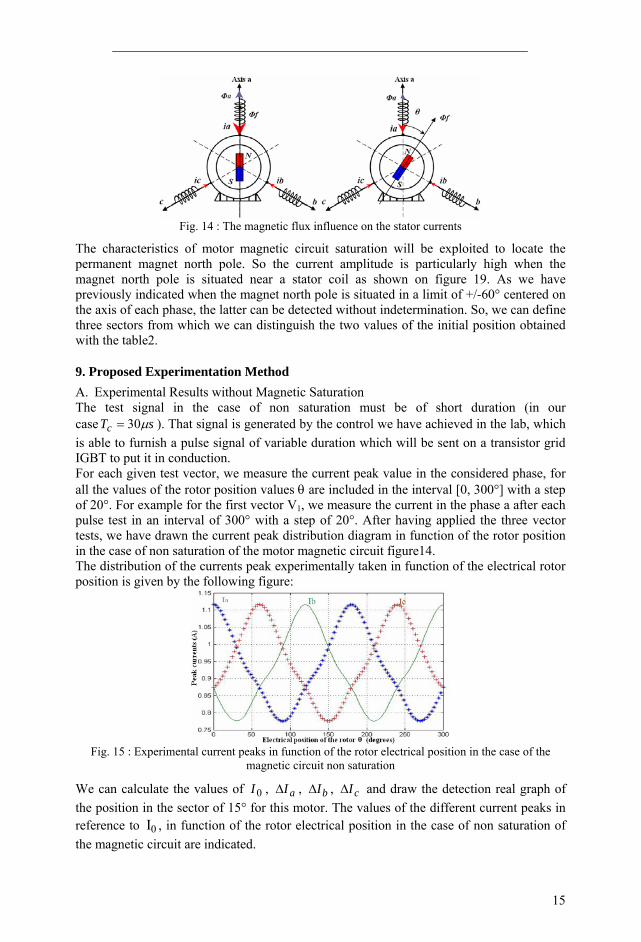
Fig. 14 : The magnetic flux influence on the stator currents
The characteristics of motor magnetic circuit saturation will be exploited to locate the permanent magnet north pole. So the current amplitude is particularly high when the magnet north pole is situated near a stator coil as shown on figure 19. As we have previously indicated when the magnet north pole is situated in a limit of +/-60° centered on the axis of each phase, the latter can be detected without indetermination. So, we can define three sectors from which we can distinguish the two values of the initial position obtained with the table2.
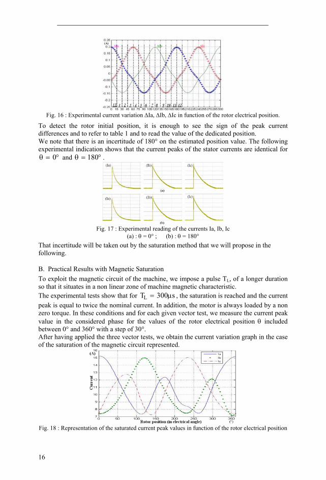
9. Proposed Experimentation Method A. Experimental Results without Magnetic Saturation The test signal in the case of non saturation must be of short duration (in our case sTc μ30= ). That signal is generated by the control we have achieved in the lab, which is able to furnish a pulse signal of variable duration which will be sent on a transistor grid IGBT to put it in conduction. For each given test vector, we measure the current peak value in the considered phase, for all the values of the rotor position values θ are included in the interval [0, 300°] with a step of 20°. For example for the first vector V1, we measure the current in the phase a after each pulse test in an interval of 300° with a step of 20°. After having applied the three vector tests, we have drawn the current peak distribution diagram in function of the rotor position in the case of non saturation of the motor magnetic circuit figure14. The distribution of the currents peak experimentally taken in function of the electrical rotor position is given by the following figure:
Fig. 15 : Experimental current peaks in function of the rotor electrical position in the case of the
magnetic circuit non saturation
We can calculate the values of 0I , aIΔ , bIΔ , cIΔ and draw the detection real graph of the position in the sector of 15° for this motor. The values of the different current peaks in reference to 0I , in function of the rotor electrical position in the case of non saturation of the magnetic circuit are indicated.
16
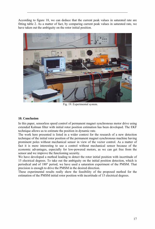
Fig. 16 : Experimental current variation ΔIa, ΔIb, ΔIc in function of the rotor electrical position.
To detect the rotor initial position, it is enough to see the sign of the peak current differences and to refer to table 1 and to read the value of the dedicated position. We note that there is an incertitude of 180° on the estimated position value. The following experimental indication shows that the current peaks of the stator currents are identical for
°=θ 0 and °=θ 180 .
Fig. 17 : Experimental reading of the currents Ia, Ib, Ic
(a) : θ = 0° ; (b) : θ = 180°
That incertitude will be taken out by the saturation method that we will propose in the following.
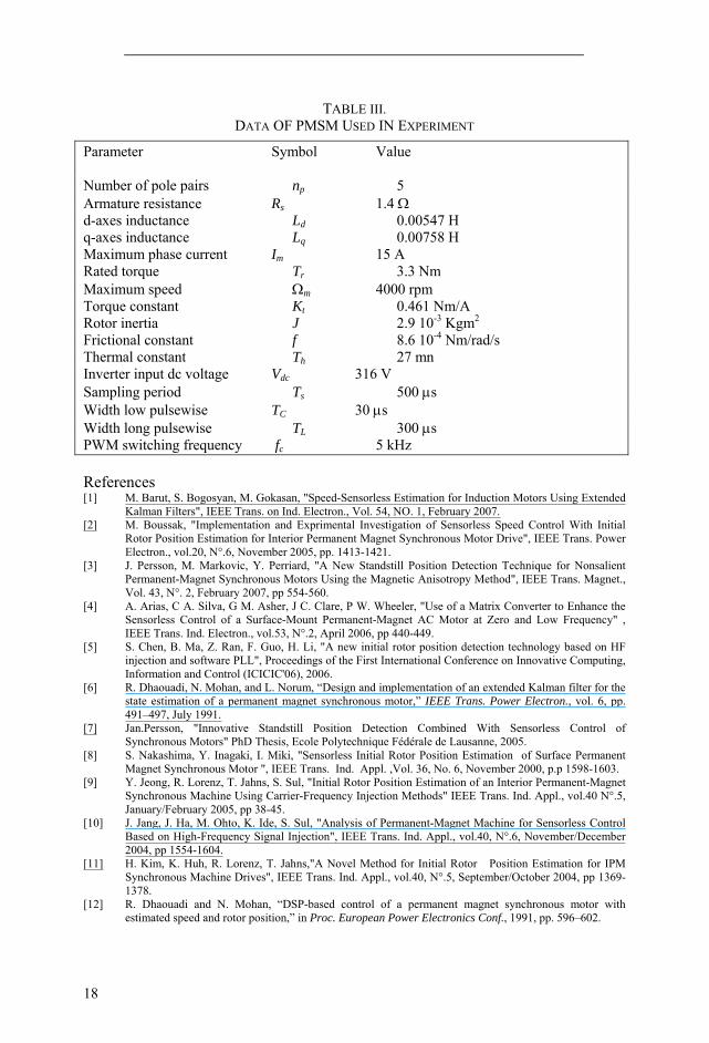
B. Practical Results with Magnetic Saturation To exploit the magnetic circuit of the machine, we impose a pulse TL, of a longer duration so that it situates in a non linear zone of machine magnetic characteristic. The experimental tests show that for s300TL μ= , the saturation is reached and the current peak is equal to twice the nominal current. In addition, the motor is always loaded by a non zero torque. In these conditions and for each given vector test, we measure the current peak value in the considered phase for the values of the rotor electrical position θ included between 0° and 360° with a step of 30°. After having applied the three vector tests, we obtain the current variation graph in the case of the saturation of the magnetic circuit represented.
Fig. 18 : Representation of the saturated current peak values in function of the rotor electrical position
17
According to figure 18, we can deduce that the current peak values in saturated rate are fitting table 2. As a matter of fact, by comparing current peak values in saturated rate, we have taken out the ambiguity on the rotor initial position.
Fig. 19. Experimental system.
10. Conclusion In this paper, sensorless speed control of permanent magnet synchronous motor drive using extended Kalman filter with initial rotor position estimation has been developed. The EKF technique allows us to estimate the position in dynamic rate. The work here presented is listed in a wider context for the research of a new detection technique of the initial rotor position of the permanent magnet synchronous machine having prominent poles without mechanical sensor in view of the vector control. As a matter of fact it is more interesting to use a control without mechanical sensor because of the economic advantages, especially for low-powered motors, as we can get free from the sensor and we improve the functioning security. We have developed a method leading to detect the rotor initial position with incertitude of 15 electrical degrees. To take out the ambiguity on the initial position detection, which is periodical and of 180° period, we have used a saturation experiment of the PMSM. That precision is enough to drive the PMSM in the desired direction. These experimental results really show the feasibility of the proposed method for the estimation of the PMSM initial rotor position with incertitude of 15 electrical degrees.
18
TABLE III.
DATA OF PMSM USED IN EXPERIMENT
Parameter Symbol Value Number of pole pairs np 5 Armature resistance Rs 1.4 Ω d-axes inductance Ld 0.00547 H q-axes inductance Lq 0.00758 H Maximum phase current Im 15 A Rated torque Tr 3.3 Nm Maximum speed Ωm 4000 rpm Torque constant Kt 0.461 Nm/A Rotor inertia J 2.9 10-3 Kgm2 Frictional constant f 8.6 10-4 Nm/rad/s Thermal constant Th 27 mn Inverter input dc voltage Vdc 316 V Sampling period Ts 500 μs Width low pulsewise TC 30 μs Width long pulsewise TL 300 μs PWM switching frequency fc 5 kHz References [1] M. Barut, S. Bogosyan, M. Gokasan, "Speed-Sensorless Estimation for Induction Motors Using Extended
Kalman Filters", IEEE Trans. on Ind. Electron., Vol. 54, NO. 1, February 2007. [2] M. Boussak, "Implementation and Exprimental Investigation of Sensorless Speed Control With Initial
Rotor Position Estimation for Interior Permanent Magnet Synchronous Motor Drive", IEEE Trans. Power Electron., vol.20, N°.6, November 2005, pp. 1413-1421.
[3] J. Persson, M. Markovic, Y. Perriard, "A New Standstill Position Detection Technique for Nonsalient Permanent-Magnet Synchronous Motors Using the Magnetic Anisotropy Method", IEEE Trans. Magnet., Vol. 43, N°. 2, February 2007, pp 554-560.
[4] A. Arias, C A. Silva, G M. Asher, J C. Clare, P W. Wheeler, "Use of a Matrix Converter to Enhance the Sensorless Control of a Surface-Mount Permanent-Magnet AC Motor at Zero and Low Frequency" , IEEE Trans. Ind. Electron., vol.53, N°.2, April 2006, pp 440-449.
[5] S. Chen, B. Ma, Z. Ran, F. Guo, H. Li, "A new initial rotor position detection technology based on HF injection and software PLL", Proceedings of the First International Conference on Innovative Computing, Information and Control (ICICIC'06), 2006.
[6] R. Dhaouadi, N. Mohan, and L. Norum, “Design and implementation of an extended Kalman filter for the state estimation of a permanent magnet synchronous motor,” IEEE Trans. Power Electron., vol. 6, pp. 491–497, July 1991.
[7] Jan.Persson, "Innovative Standstill Position Detection Combined With Sensorless Control of Synchronous Motors" PhD Thesis, Ecole Polytechnique Fédérale de Lausanne, 2005.
[8] S. Nakashima, Y. Inagaki, I. Miki, "Sensorless Initial Rotor Position Estimation of Surface Permanent Magnet Synchronous Motor ", IEEE Trans. Ind. Appl. ,Vol. 36, No. 6, November 2000, p.p 1598-1603.
[9] Y. Jeong, R. Lorenz, T. Jahns, S. Sul, "Initial Rotor Position Estimation of an Interior Permanent-Magnet Synchronous Machine Using Carrier-Frequency Injection Methods" IEEE Trans. Ind. Appl., vol.40 N°.5, January/February 2005, pp 38-45.
[10] J. Jang, J. Ha, M. Ohto, K. Ide, S. Sul, "Analysis of Permanent-Magnet Machine for Sensorless Control Based on High-Frequency Signal Injection", IEEE Trans. Ind. Appl., vol.40, N°.6, November/December 2004, pp 1554-1604.
[11] H. Kim, K. Huh, R. Lorenz, T. Jahns,"A Novel Method for Initial Rotor Position Estimation for IPM Synchronous Machine Drives", IEEE Trans. Ind. Appl., vol.40, N°.5, September/October 2004, pp 1369-1378.
[12] R. Dhaouadi and N. Mohan, “DSP-based control of a permanent magnet synchronous motor with estimated speed and rotor position,” in Proc. European Power Electronics Conf., 1991, pp. 596–602.

19
[13] U. H. Rieder, M. Schroedl, A. Ebner, "Sensorless Control of an External Rotor PMSM in the Whole: Speed Range including Standstill using DC-link Measurements only", 2004 35th Annual IEEE Power Electronics Specialists Conference Aachen, Germany, 2004.
[14] J. Jang, S. Sul, J. Ha, K. Ide, M. Sawamura, "Sensorless Drive of Surface-Mounted Permanent-Magnet Motor by High-Frequency Signal Injection Based on Magnetic Saliency", IEEE Trans. Ind. Applicat. , vol.39, N°.4, July/August 2003, pp.1031-1039.
[15] M.Enamul Haque, L. Zhong, M. Fazlur Rahman, "A Sensorless Initial Rotor Position Estimation Scheme for a Direct Torque Controlled Interior Permanent Magnet Synchronous Motor Drive", IEEE Trans. Power Electron., vol.18, N°.6, November 2003, pp. 1376-1383.
[16] T. Aihara, A. Toba, T. Yanase, A. Mashimo, K. Endo, "Sensorless Torque Control of Salient-Pole Synchronous Motor at Zero-Speed Operation", IEEE Trans. Power Electron., vol.14, N°.1, January 2003, pp. 1376-1383.
[17] D. Howe, Z. Q. Zhu, "Sensorless PM Brushless Drives", IEEE UK chapter seminar, 15 December 2003. [18] M. Tursini, R. Petrella, F. Parasiliti, "Initial Rotor Position Estimation Method for PM Motors ", IEEE
Trans. on Ind. Applicat., vol. 39, n°. 6, Nov./Dec. 2003. [19] S. Bolognani, L. Tubiana, M. Zigliotto, "Extended Kalman Filter Tuning in Sensorless PMSM Drives",
IEEE Trans. Ind. Applicat. , vol.39, N°.6, November/December 2003, pp.1741-1747. [20] M. Boussak "Digital signal processor based sensorless speed control of a permanent magnet synchronous
motor drive using extended Kalman filter", EPE Journal vol. 11 n°3 pp. 7-15, August 2001. [21] J. Holtz, "Sensorless Speed and position Control Of Inductions Motors ", 27 th annual Conference of the
IEEE Industrial Electronics Society, IECON, Denver /Co, Nov.29-Dec.2, 2001. [22] M. J. Corley, R. D. Lorenz, "Rotor Position and Velocity Estimation for a Salient-Pole Permanent Magnet
Synchronous Machine at Standstill and High Speeds", IEEE Trans. Ind. Appl., vol.. 34, n°. 4, July/Aug. 1998.
Related Documents