International Journal of Research and Engineering Volume 2, Issue 2 25 http://www.ijre.org ISSN 2348-7852 (Print) | ISSN 2348-7860 (Online) Sensorless Control of BLDC Motor Drive Using a Hysteresis Comparator and back emf technique S.MEIVEL 1 , & A.VENNILA 2 & A.GOVINDARASU 3 1 ASSISTANT PROFESSOR, JAY SHRIRAM GROUP OF INSTITUTIONS, TIRUPUR, 2,3 , UG STUDENTS, FINAL YEAR-EEE, JAY SHRIRAM GROUP OF INSTITUTIONS, TIRUPUR. Abstract- This paper describes the brushless dc (BLDC) motor sensorless control system for hydraulic oil pump. The sensorless techniques that are based on a hysteresis comparator the basic implementation of hysteresis current control is based on deriving the switching signals from the comparison of the current and voltage method with a high starting torque are suggested. The hysteresis comparator is used to compensate for the phase delay of the back EMFs. The concept of the application is that of a drive using Back-EMF Zero Crossing technique for position detection. It prevent multiple output transitions from noise or ripple in the terminal voltages. The rotor position is aligned at standstill for maximum starting torque. Also, the stator current can be easily adjusted by modulating the pulse width of the switching devices during alignment. Some experiments are implemented on a single chip PIC controller to demonstrate the feasibility of the suggested sensorless and start-up techniques. Index Terms-Brushless dc (BLDC) motor, hysteresis comparator, sensorless control, start-up technique. I. INTRODUCTION In recent years, the brushless dc (BLDC) motor is receiving much interest in automotive applications especially on hydraulic oil pump due to its high efficiency, compact size, and lower maintenance when compared to a brush dc motor. In order to obtain an accurate and ripple-free instantaneous torque of the BLDC motor, the rotor position information for stator current commutation must be known, which can be obtained using hall or position sensors mounted on a rotor. This results in a high costs as well as poor reliability, which are serious problems at the vehicle applications. To cope with the aforementioned restriction, many position sensorless algorithms have been considered as potential solutions. Three phase Brushless DC (BLDC) motors are good candidates because of their high efficiency capability and easy to drive features. The disadvantage of this kind of motor is the fact that commutation of motor phases relies on its rotor position. Although the rotor position is usually sensed by sensors, there are applications that require sensorless control. Benefits of the sensorless solution are elimination of the position sensor and its connections between the control unit and the motor. The sensor less rotor position technique detects the zero crossing points of Back-EMF induced in the motor windings. The phase Back-EMF Zero Crossing points are sensed while one of the three phase windings is not powered. The obtained information is processed in order to commutate energized phase pair and control the phase voltage, using Pulse Width Modulation. The zero-crossing of the back EMF measured from the stator winding is detected and the commutation points can be estimated by shifting 30 from the zero crossing of the back EMFs. The performance of the sensorless drive Deteriorates with the phase shifter in the transient state. Also, it is sensitive to the phase delay especially at the high speed. Several phase shifters to compensate for phase error induced of back EMFs are proposed. They require an additional compensation circuit including the timers. The position information is extracted by integrating the back EMF of the silent phase. This method has an error accumulation problem at low speed. The sensorless control techniques using the phase-locked loop (PLL) and the third-harmonic back EMF are suggested. Furthermore, the drift angle varies as the motor parameters, speed, and load conditions change. The improved sensorless controller by removing the effect of the freewheel diode conduction is suggested. Some approaches use the zero crossing points of three-phase line-to-line voltages, so that they coincide to six commutation points. Although the commutation signals can be obtained without any phase shifter, the phase delay could not be considered and the multiple output transitions of the comparator may occur from the high frequency ripple or noise in the back EMFs. The zero-crossing point of the back EMF for generating proper commutation control of the inverter is calculated by sampling the voltage of the floating phase without using current and position sensors. Most sensorless techniques are based on back EMF estimation. , when a motor is at standstill or very low speed, it is well known that the back EMF is zero to estimate a precise rotor position. Therefore, a specific start-up process in sensorless drive systems is required. The general solution to the problem is the open-loop start-up method named “align and go”. The procedure is to excite two phases of the three phase windings for a preset time. BLDC Motor Targeted by This Application The Brushless DC motor (BLDC motor) is also referred to as an electronically commuted motor. There are no brushes on the rotor and the commutation is performed electronically at certain rotor positions. The stator magnetic circuit is usually made from magnetic steel sheets. The stator phase windings are inserted in the slots (distributed winding) as shown in Figure (a) or it can be wound as one coil on the magnetic pole. The magnetization of the permanent magnets and their displacement on the rotor are chosen such a way that the Back-EMF (the voltage induced into the stator winding due to rotor movement) shape is trapezoidal. This allows the three phase voltage system with a rectangular shape, to be used to create a rotational field with low torque ripples. The permanent magnet rotor will then rotate to align to a specific position. With a known initial rotor position and a given

Welcome message from author
This document is posted to help you gain knowledge. Please leave a comment to let me know what you think about it! Share it to your friends and learn new things together.
Transcript
International Journal of Research and Engineering Volume 2, Issue 2
25 http://www.ijre.org
ISSN 2348-7852 (Print) | ISSN 2348-7860 (Online)
Sensorless Control of BLDC Motor Drive Using a Hysteresis
Comparator and back emf technique
S.MEIVEL1, & A.VENNILA
2 &A.GOVINDARASU
3
1ASSISTANT PROFESSOR, JAY SHRIRAM GROUP OF INSTITUTIONS, TIRUPUR,
2,3 ,UG STUDENTS, FINAL YEAR-EEE, JAY SHRIRAM GROUP OF INSTITUTIONS, TIRUPUR.
Abstract- This paper describes the brushless dc (BLDC)
motor sensorless control system for hydraulic oil pump. The
sensorless techniques that are based on a hysteresis
comparator the basic implementation of hysteresis current
control is based on deriving the switching signals from the
comparison of the current and voltage method with a high
starting torque are suggested. The hysteresis comparator is
used to compensate for the phase delay of the back EMFs. The
concept of the application is that of a drive using Back-EMF
Zero Crossing technique for position detection. It prevent
multiple output transitions from noise or ripple in the terminal
voltages. The rotor position is aligned at standstill for
maximum starting torque. Also, the stator current can be easily
adjusted by modulating the pulse width of the switching
devices during alignment. Some experiments are implemented
on a single chip PIC controller to demonstrate the feasibility
of the suggested sensorless and start-up techniques. Index
Terms-Brushless dc (BLDC) motor, hysteresis comparator,
sensorless control, start-up technique.
I. INTRODUCTION
In recent years, the brushless dc (BLDC) motor is
receiving much interest in automotive applications especially
on hydraulic oil pump due to its high efficiency, compact size,
and lower maintenance when compared to a brush dc motor.
In order to obtain an accurate and ripple-free instantaneous
torque of the BLDC motor, the rotor position information for
stator current commutation must be known, which can be
obtained using hall or position sensors mounted on a rotor.
This results in a high costs as well as poor reliability, which
are serious problems at the vehicle applications. To cope with
the aforementioned restriction, many position sensorless
algorithms have been considered as potential solutions. Three
phase Brushless DC (BLDC) motors are good candidates
because of their high efficiency capability and easy to drive
features. The disadvantage of this kind of motor is the fact that
commutation of motor phases relies on its rotor position.
Although the rotor position is usually sensed by sensors, there
are applications that require sensorless control. Benefits of the
sensorless solution are elimination of the position sensor and
its connections between the control unit and the motor.
The sensor less rotor position technique detects the zero
crossing points of Back-EMF induced in the motor windings.
The phase Back-EMF Zero Crossing points are sensed while
one of the three phase windings is not powered. The obtained
information is processed in order to commutate energized
phase pair and control the phase voltage, using Pulse Width
Modulation. The zero-crossing of the back EMF measured
from the stator winding is detected and the commutation
points can be estimated by shifting 30 from the zero crossing
of the back EMFs. The performance of the sensorless drive
Deteriorates with the phase shifter in the transient state. Also,
it is sensitive to the phase delay especially at the high speed.
Several phase shifters to compensate for phase error induced
of back EMFs are proposed. They require an additional
compensation circuit including the timers. The position
information is extracted by integrating the back EMF of the
silent phase. This method has an error accumulation problem
at low speed. The sensorless control techniques using the
phase-locked loop (PLL) and the third-harmonic back EMF
are suggested. Furthermore, the drift angle varies as the motor
parameters, speed, and load conditions change. The improved
sensorless controller by removing the effect of the freewheel
diode conduction is suggested. Some approaches use the zero
crossing points of three-phase line-to-line voltages, so that
they coincide to six commutation points. Although the
commutation signals can be obtained without any phase
shifter, the phase delay could not be considered and the
multiple output transitions of the comparator may occur from
the high frequency ripple or noise in the back EMFs. The
zero-crossing point of the back EMF for generating proper
commutation control of the inverter is calculated by sampling
the voltage of the floating phase without using current and
position sensors. Most sensorless techniques are based on back
EMF estimation. , when a motor is at standstill or very low
speed, it is well known that the back EMF is zero to estimate a
precise rotor position. Therefore, a specific start-up process in
sensorless drive systems is required. The general solution to
the problem is the open-loop start-up method named “align
and go”. The procedure is to excite two phases of the three
phase windings for a preset time. BLDC Motor Targeted by
This Application The Brushless DC motor (BLDC motor) is
also referred to as an electronically commuted motor. There
are no brushes on the rotor and the commutation is performed
electronically at certain rotor positions. The stator magnetic
circuit is usually made from magnetic steel sheets. The stator
phase windings are inserted in the slots (distributed winding)
as shown in Figure (a) or it can be wound as one coil on the
magnetic pole. The magnetization of the permanent magnets
and their displacement on the rotor are chosen such a way that
the Back-EMF (the voltage induced into the stator winding
due to rotor movement) shape is trapezoidal. This allows the
three phase voltage system with a rectangular shape, to be
used to create a rotational field with low torque ripples. The
permanent magnet rotor will then rotate to align to a specific
position. With a known initial rotor position and a given
International Journal of Research and Engineering Volume 2, Issue 2
26 http://www.ijre.org
ISSN 2348-7852 (Print) | ISSN 2348-7860 (Online)
commutation logic, an open loop control scheme is then
applied to accelerate the motor from a standstill. Although this
technique can be applied to certain automotive applications.
Fig.1 Block diagram
Fig. 1. Block diagram of sensorless control by using a
hysteresis comparator. Smoothly from standstill without any
position sensors by utilizing the inductance variation
technique. This is done by monitoring the current responses to
the inductance variation on the rotor position. Although these
methods can detect a precise rotor position at standstill, they
result in a complex control algorithm and an increase of the
system costs due to an additional current sensor. Instead of the
detection of current, only terminal voltage level is used for
detection of the initial position of the permanent magnet.which
requires the good reliability, a wide speed range from 3000 to
9000 rpm, fast start up, and high starting torque for the
sensorless BLDC motor drive systems. To satisfy these
requirements, this paper presents a sensorless control based on
a hysteresis comparator of terminal voltage and a potential
start-up method with a high starting torque. The hysteresis
comparator is used to compensate for the phase lag due to
prevent multiple output transitions from noise or ripple in the
terminal voltages. It is able to improve both the performance
and reliability for the sensorless BLDC motor drive system.
Some experiments are implemented on a PIC controller to
justify the feasibility of the suggested sensorless and start-up
techniques.
II. SENSORLESS CONTROL USING HYSTERESIS
COMPARATOR
Fig. 1 shows the block diagram of a sensorless control by
using a hysteresis comparator method. It consists for
suppressing the high switching frequency ripples, hysteresis
comparators for generating three-phase commutation signals,
and a gating signals generator for generating six PWM signals.
After sensing the three-phase terminal voltages, each of the
three-phase terminal voltages is fed to suppress the high
switching frequency ripple or noise. As only two phases of the
BLDC motor are energized at any time, the back EMF can be
measured from its terminal voltage in the period of an open
phase. During the two-phase conduction period, the only
difference between the back EMF and its terminal voltage is a
stator impedance voltage drop, which may be considerably
small compared with the dc voltage source. Therefore, Plots of
phase lag to various rotor speeds under a variation of the cut-
off frequency of the LPF. As the rotor speed increases, the
percentage contribution of the phase lag to the overall period
increases. The lag will disturb current alignment with the back
EMF and will cause serious problems for commutation at high
speed. The phase lag in commutation can produce significant
pulsating torques in such drive which may cause oscillations
of the rotor speed, and generate extra copper losses. In this
paper, the cut-off frequency of the determined on 2.5 kHz by
considering both the phase lag and harmonic distribution of
the back EMF. The hysteresis comparator is used to
compensate for the phase lag of the back EMFs due to the LPF
in order to determine the proper commutation sequence of the
inverter according to the rotor position. Also, it can prevent
multiple output transitions by high frequency ripples in the
terminal voltages. The outputs of the three-phase hysteresis
comparators become three commutation signals (Za, Zb, Zc ),
and then six gating signals can be generated through some
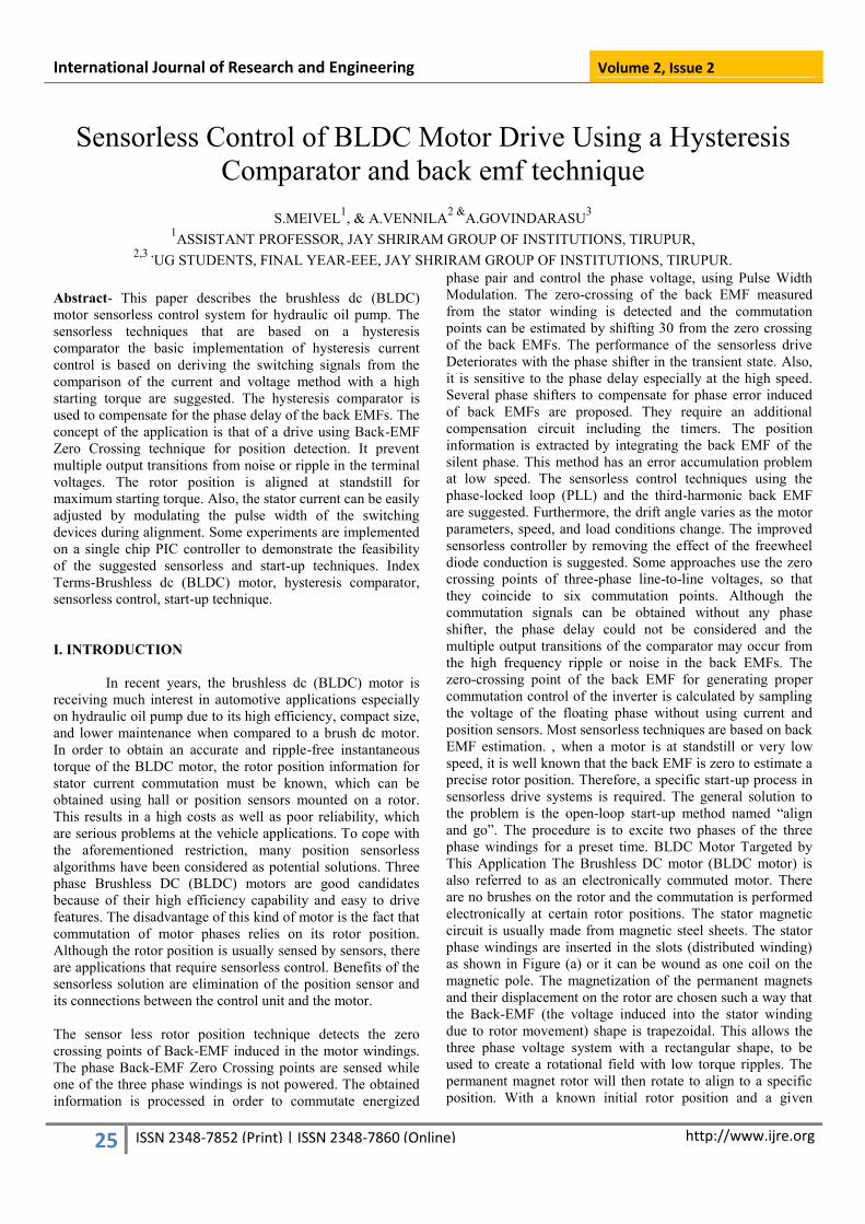
logic equations. The operation of the a-phase hysteresis
comparator is explained in Fig. 3. The filtered a-phase
terminal voltage is applied to the inverting input, and the
filtered c-phase terminal voltage is applied via R1 to the non-
inverting input. A differential voltage of a-phase hysteresis
comparator.
Fig -12 Hysteresis comparator
International Journal of Research and Engineering Volume 2, Issue 2
27 http://www.ijre.org
ISSN 2348-7852 (Print) | ISSN 2348-7860 (Online)
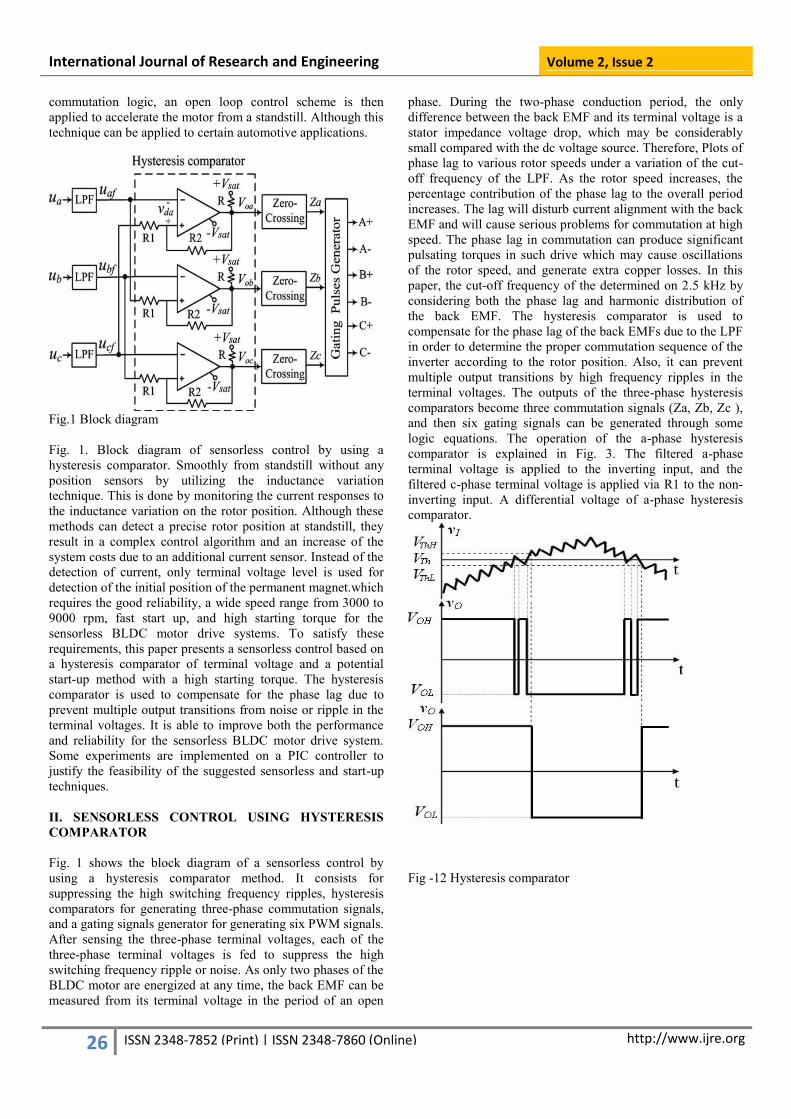
Fig. 2. Plot of the phase delay, the advanced angle, and the
phase shift after compensation.
Fig-12(a) operation of Hysteresis comparator
The advanced angle θa is determined by the values of n, Vsat
,and Vp , where the Vp is nearly proportional to the rotor
speed. Fig. 4 shows plots of the angle θa for various rotor
speeds under various resistance ratios, when the Vsat is +1.2
V. The θa increases as the resistor ratio decreases or the rotor
speed decreases. Therefore, the phase lag at the overall speed
range can be compensated by adjusting the resistance ratio of
the hysteresis comparator. The resistance ratio is determined
to 1.2 in order that the gating signal can be nearly kept in
phase with the back EMF when the motor is at the nominal
speed, 6000 rpm. The hysteresis band can be calculated at +1
V because the Vsat is +1.2 V and the resistance ratio n is 1.2.
Thus, if a peak of ripple voltage in the terminal voltage is
within the hysteresis band+1Vregardless of magnitude of the
terminal voltage, it can prevent multiple output transitions at a
hysteresis comparator by high frequency ripples in the
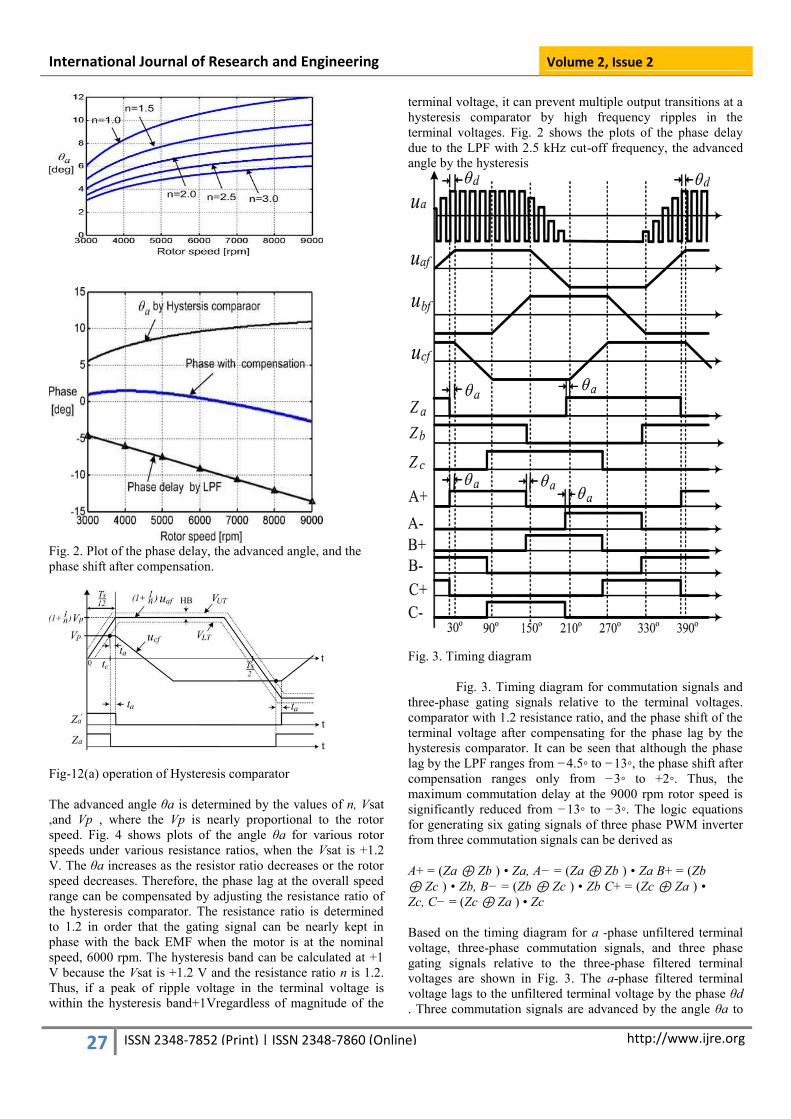
terminal voltages. Fig. 2 shows the plots of the phase delay
due to the LPF with 2.5 kHz cut-off frequency, the advanced
angle by the hysteresis
Fig. 3. Timing diagram
Fig. 3. Timing diagram for commutation signals and
three-phase gating signals relative to the terminal voltages.
comparator with 1.2 resistance ratio, and the phase shift of the
terminal voltage after compensating for the phase lag by the
hysteresis comparator. It can be seen that although the phase
lag by the LPF ranges from −4.5◦ to −13◦, the phase shift after
compensation ranges only from −3◦ to +2◦. Thus, the
maximum commutation delay at the 9000 rpm rotor speed is
significantly reduced from −13◦ to −3◦. The logic equations
for generating six gating signals of three phase PWM inverter
from three commutation signals can be derived as
A+ = (Za ⊕ Zb ) • Za, A− = (Za ⊕ Zb ) • Za B+ = (Zb
⊕ Zc ) • Zb, B− = (Zb ⊕ Zc ) • Zb C+ = (Zc ⊕ Za ) •
Zc, C− = (Zc ⊕ Za ) • Zc
Based on the timing diagram for a -phase unfiltered terminal
voltage, three-phase commutation signals, and three phase
gating signals relative to the three-phase filtered terminal
voltages are shown in Fig. 3. The a-phase filtered terminal
voltage lags to the unfiltered terminal voltage by the phase θd
. Three commutation signals are advanced by the angle θa to
International Journal of Research and Engineering Volume 2, Issue 2
28 http://www.ijre.org
ISSN 2348-7852 (Print) | ISSN 2348-7860 (Online)
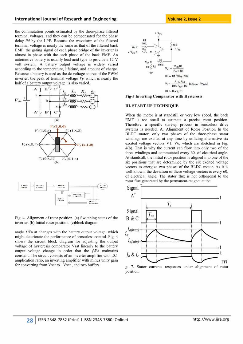
the commutation points estimated by the three-phase filtered
terminal voltages, and they can be compensated for the phase
delay θd by the LPF. Because the waveform of the filtered
terminal voltage is nearly the same as that of the filtered back
EMF, the gating signal of each phase bridge of the inverter is
almost in phase with the each phase of the back EMF. An
automotive battery is usually lead-acid type to provide a 12-V
volt system. A battery output voltage is widely varied
according to the temperature, lifetime, and amount of charge.
Because a battery is used as the dc voltage source of the PWM
inverter, the peak of terminal voltage Vp which is nearly the
half of a battery output voltage, is also varied.
Fig. 4. Alignment of rotor position. (a) Switching states of the
inverter. (b) Initial rotor position. (c)block diagram
angle Įa at changes with the battery output voltage, which
might deteriorate the performance of sensorless control. Fig. 4
shows the circuit block diagram for adjusting the output
voltage of hysteresis comparator Vsat linearly to the battery
output voltage change in order that the Įa maintains
constant. The circuit consists of an inverter amplifier with .0.1
amplication ratio, an inverting amplifier with minus unity gain
for converting from Vsat to +Vsat , and two buffers.
Fig-5 Inverting Comparator with Hysteresis
III. START-UP TECHNIQUE
When the motor is at standstill or very low speed, the back
EMF is too small to estimate a precise rotor position.
Therefore, a specific start-up process in sensorless drive
systems is needed. A. Alignment of Rotor Position In the
BLDC motor, only two phases of the three-phase stator
windings are excited at any time by utilizing alternative six
excited voltage vectors V1. V6, which are sketched in Fig.
4(b). That is why the current can flow into only two of the
three windings and commutated every 60. of electrical angle.
At standstill, the initial rotor position is aligned into one of the
six positions that are determined by the six excited voltage
vectors to energize two phases of the BLDC motor. As it is
well known, the deviation of these voltage vectors is every 60.
of electrical angle. The stator flux is not orthogonal to the
rotor flux generated by the permanent-magnet at the
FFi
g. 7. Stator currents responses under alignment of rotor
position.
International Journal of Research and Engineering Volume 2, Issue 2
29 http://www.ijre.org
ISSN 2348-7852 (Print) | ISSN 2348-7860 (Online)
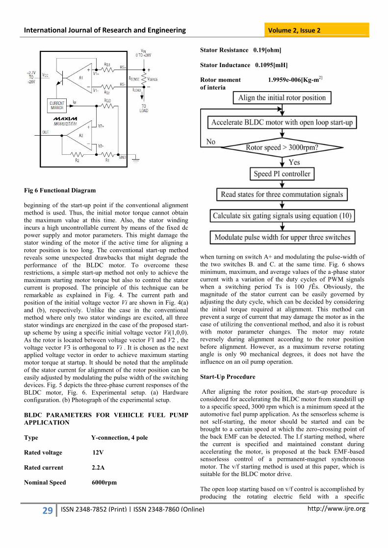
Fig 6 Functional Diagram
beginning of the start-up point if the conventional alignment
method is used. Thus, the initial motor torque cannot obtain
the maximum value at this time. Also, the stator winding
incurs a high uncontrollable current by means of the fixed dc
power supply and motor parameters. This might damage the
stator winding of the motor if the active time for aligning a
rotor position is too long. The conventional start-up method
reveals some unexpected drawbacks that might degrade the
performance of the BLDC motor. To overcome these
restrictions, a simple start-up method not only to achieve the
maximum starting motor torque but also to control the stator
current is proposed. The principle of this technique can be
remarkable as explained in Fig. 4. The current path and
position of the initial voltage vector Vi are shown in Fig. 4(a)
and (b), respectively. Unlike the case in the conventional
method where only two stator windings are excited, all three
stator windings are energized in the case of the proposed start-
up scheme by using a specific initial voltage vector Vi(1,0,0).
As the rotor is located between voltage vector V1 and V2 , the
voltage vector V3 is orthogonal to Vi . It is chosen as the next
applied voltage vector in order to achieve maximum starting
motor torque at startup. It should be noted that the amplitude
of the stator current for alignment of the rotor position can be
easily adjusted by modulating the pulse width of the switching
devices. Fig. 5 depicts the three-phase current responses of the
BLDC motor, Fig. 6. Experimental setup. (a) Hardware
configuration. (b) Photograph of the experimental setup.
BLDC PARAMETERS FOR VEHICLE FUEL PUMP
APPLICATION
Type Y-connection, 4 pole
Rated voltage 12V
Rated current 2.2A
Nominal Speed 6000rpm
Stator Resistance 0.19[ohm]
Stator Inductance 0.1095[mH]
Rotor moment 1.9959e-006[Kg-m2]
of interia
when turning on switch A+ and modulating the pulse-width of
the two switches B. and C. at the same time. Fig. 6 shows
minimum, maximum, and average values of the a-phase stator
current with a variation of the duty cycles of PWM signals
when a switching period Ts is 100 ƒÊs. Obviously, the
magnitude of the stator current can be easily governed by
adjusting the duty cycle, which can be decided by considering
the initial torque required at alignment. This method can
prevent a surge of current that may damage the motor as in the
case of utilizing the conventional method, and also it is robust
with motor parameter changes. The motor may rotate
reversely during alignment according to the rotor position
before alignment. However, as a maximum reverse rotating
angle is only 90 mechanical degrees, it does not have the
influence on an oil pump operation.
Start-Up Procedure
After aligning the rotor position, the start-up procedure is
considered for accelerating the BLDC motor from standstill up
to a specific speed, 3000 rpm which is a minimum speed at the
automotive fuel pump application. As the sensorless scheme is
not self-starting, the motor should be started and can be
brought to a certain speed at which the zero-crossing point of
the back EMF can be detected. The I.f starting method, where
the current is specified and maintained constant during
accelerating the motor, is proposed at the back EMF-based
sensorlesss control of a permanent-magnet synchronous
motor. The v/f starting method is used at this paper, which is
suitable for the BLDC motor drive.
The open loop starting based on v/f control is accomplished by
producing the rotating electric field with a specific
International Journal of Research and Engineering Volume 2, Issue 2
30 http://www.ijre.org
ISSN 2348-7852 (Print) | ISSN 2348-7860 (Online)
relationship to the reference voltage in terms of a rotor speed.
As the frequency is gradually increased, the rotor speed also
increases. The magnitude of a reference voltage is adjusted as
proportional to the rotor speed. A phase angle can be obtained
from integrating the rotor speed and the pulse width of the
gating signals is modulated with the reference voltage
magnitude. The six PWM signals with 60. phase displacement
are generated corresponding to the phase angle without any
rotor position information. When the rotor speed reaches at
3000 rpm, the back EMF can be sensed to provide the rotor
position information and the system is switched to the
sensorless control.
IV. EXPERIMENTAL RESULTS
A. Hardware and Software Configurations the experimental
system that was set up to validate the proposed method is
shown in Fig. 6. The control system is implemented by a 16-
bit PIC type 18F4431 operating with a clock frequency of
16MHz and the sampling interval is 50 ƒÊs for both the start-
up and sensorless controls. As shown in Fig. 6, the PIC
generates six PWM signals and also measures a rotor speed by
using the three-phase commutation signals.The reference
speed, rotor speed, and the reference stator voltage shown in
the experimental results are converted into analog signals
through a 12-bit 4-channel D/A.
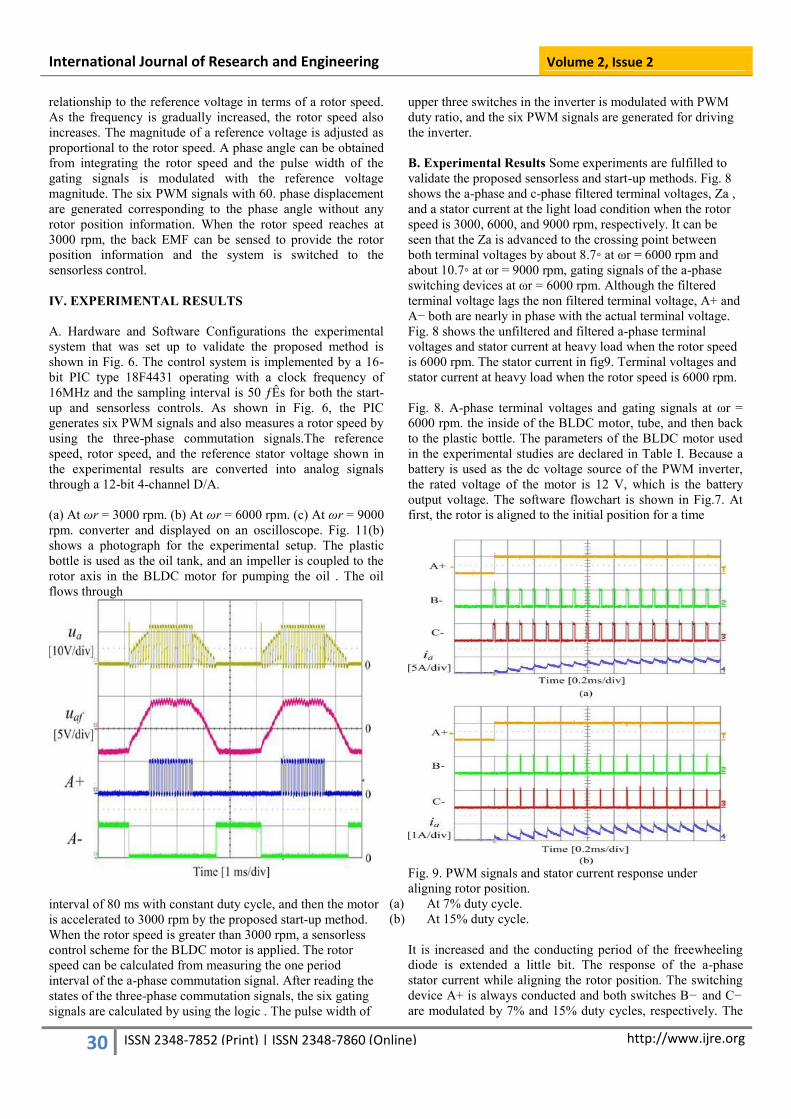
(a) At ωr = 3000 rpm. (b) At ωr = 6000 rpm. (c) At ωr = 9000
rpm. converter and displayed on an oscilloscope. Fig. 11(b)
shows a photograph for the experimental setup. The plastic
bottle is used as the oil tank, and an impeller is coupled to the
rotor axis in the BLDC motor for pumping the oil . The oil
flows through
interval of 80 ms with constant duty cycle, and then the motor
is accelerated to 3000 rpm by the proposed start-up method.
When the rotor speed is greater than 3000 rpm, a sensorless
control scheme for the BLDC motor is applied. The rotor
speed can be calculated from measuring the one period
interval of the a-phase commutation signal. After reading the
states of the three-phase commutation signals, the six gating
signals are calculated by using the logic . The pulse width of
upper three switches in the inverter is modulated with PWM
duty ratio, and the six PWM signals are generated for driving
the inverter.
B. Experimental Results Some experiments are fulfilled to
validate the proposed sensorless and start-up methods. Fig. 8
shows the a-phase and c-phase filtered terminal voltages, Za ,
and a stator current at the light load condition when the rotor
speed is 3000, 6000, and 9000 rpm, respectively. It can be
seen that the Za is advanced to the crossing point between
both terminal voltages by about 8.7◦ at ωr = 6000 rpm and
about 10.7◦ at ωr = 9000 rpm, gating signals of the a-phase
switching devices at ωr = 6000 rpm. Although the filtered
terminal voltage lags the non filtered terminal voltage, A+ and
A− both are nearly in phase with the actual terminal voltage.
Fig. 8 shows the unfiltered and filtered a-phase terminal
voltages and stator current at heavy load when the rotor speed
is 6000 rpm. The stator current in fig9. Terminal voltages and
stator current at heavy load when the rotor speed is 6000 rpm.
Fig. 8. A-phase terminal voltages and gating signals at ωr =
6000 rpm. the inside of the BLDC motor, tube, and then back
to the plastic bottle. The parameters of the BLDC motor used
in the experimental studies are declared in Table I. Because a
battery is used as the dc voltage source of the PWM inverter,
the rated voltage of the motor is 12 V, which is the battery
output voltage. The software flowchart is shown in Fig.7. At
first, the rotor is aligned to the initial position for a time
Fig. 9. PWM signals and stator current response under
aligning rotor position.
(a) At 7% duty cycle.
(b) At 15% duty cycle.
It is increased and the conducting period of the freewheeling
diode is extended a little bit. The response of the a-phase
stator current while aligning the rotor position. The switching
device A+ is always conducted and both switches B− and C−
are modulated by 7% and 15% duty cycles, respectively. The

International Journal of Research and Engineering Volume 2, Issue 2
31 http://www.ijre.org
ISSN 2348-7852 (Print) | ISSN 2348-7860 (Online)
average values of stator current are about 0.8 and 4 A when
the duty cycle is 7% and 15%, respectively.
Fig. 10. Start-up currents with a variation of the initial angle
between stator and rotor fluxes under the light load condition.
(a) At initial angle = 90◦
(b)At initial angle = 60◦
(c) At initial angle = 0◦
the magnitude of stator current can be easily controlled by the
duty cycle for aligning a rotor position. Figs. 7 and 8 show the
start-up current, the reference and rotor speeds with a variation
of the initial angle between the rotor flux of a permanent-
magnet and the stator flux generated by the stator current at
beginning of start-up mode under the light and heavy load
conditions, respectively. The system is switched Start-up
currents with a variation of the initial angle between stator and
rotor fluxes under the heavy load condition.
(a) At initial angle = 90◦
(b) At initial angle = 60◦
(c) At initial angle = 0◦
from the start-up mode to the sensorless control mode, when
the rotor speed reaches at 1500 rpm. It can be seen that the
startup current at the initial angle = 90. is lowest, and the start-
up current increases as the initial angle decreases to 0. under
both load conditions. The start-up current at the same angle is
higher under the heavy load condition. In conclusion, when
the start-up technique proposed by this paper is applied, it is
able to start up
Fig.11. Transient responses from the start-up mode to the
sensorless mode. the BLDC motor with the low current and
the possibility for the start-up failure may be reduced. Fig. 9
shows the experimental results for responses of them reference
and rotor speeds, reference voltage, and a-phase current in
order to verify the start-up technique. At first, the rotor is
aligned to the initial position for a time interval of 80 ms by
adjusting the duty cycle to 15%. After then, the motor is
accelerated to 3000 rpm by the proposed start-up method.
Subsequently, a sensorless control scheme for the BLDC
motor is applied for speeding up the motor to 6000 rpm. The
start-up time is about 0.9s, which is acceptable for hydraulic
oil pump application.
V. CONCLUSION This paper presents a sensorless control based on a hysteresis
comparator of terminal voltage and a potential start-up method
with a high starting torque for hydraulic oil pump application.
As the maximum commutation phase lag is significantly
reduced from −13◦ to −3◦ by adjusting both the resistance
ratio and the output voltage level of the hysteresis comparator,
the commutation signal is nearly in phase with the back EMF.
If a peak of ripple voltage in the terminal voltage is within the
hysteresis band +1 V regardless of magnitude of the terminal
voltage, it can prevent multiple output transitions at a
hysteresis comparator by high frequency ripples in the
terminal voltage. After aligning the rotor position for
achieving the maximum starting torque, the BLDC motor
accelerates from a standstill up to a nominal speed within 0.9 s
and any fault it can be prevented and automatic restart. The
magnitude of the stator current for aligning the rotor position
can be easily controlled by modulating the pulse width of
specific switching devices. Through the experimental results,
it can be seen that the proposed sensorless and start-up
techniques are ideally suited for the hydraulic oil pump
application.
REFERENCES
[1] P. Champa, P. Somrisi, P. Wipasuramonton, and
International Journal of Research and Engineering Volume 2, Issue 2
32 http://www.ijre.org
ISSN 2348-7852 (Print) | ISSN 2348-7860 (Online)
P. Nakmahachalasint,“Initial rotor position
estimation for sensorless brushless DC drives,”
IEEE Trans. Ind. Appl., vol. 45, no. 4, pp. 1318–
1324, Jul./Aug. 2009.
[2] P. Damodharan and K. Vasudevan, “Sensorless
brushless DC motor drive based on the zero-crossing
detection of back electromotive force (EMF) from the
line voltage difference,” IEEE Trans. Energy
Convers., vol. 25, no. 3, pp. 661–668, Sep. 2010.
[3] J. Fang, X. Zhou, and G. Liu, “Precise accelerated
torque control for small inductance brushless DC
motor,” IEEE Trans. Power Electron., vol. 28, no. 3,
pp. 1400–1412, Mar. 2013.
[4] J. Fang, X. Zhou, and G. Liu, “Instantaneous torque
control of small inductance brushless DC motor,”
IEEE Trans. Power Electron., vol. 27, no. 12, pp.
4952–4964, Dec. 2012.
[5] J. Gao and Y. Hu, “Direct self-control for BLDC
motor drives based on three-dimensional coordinate
system,” IEEE Trans. Ind. Electron., vol. 57, no. 8,
pp. 2836–2844, Aug. 2010.
[6] D. H. Jung and I. J. Ha, “Low-cost sensorless control
of brushless DC motors using a frequency-
independent phase shifter,” IEEE Trans. Power
Electron., vol. 15, no. 4, pp. 744–752, Jul. 2000.
[7] G. H. Jang, J. H. Park, and J. H. Chang,
“Position detection and start-up algorithm of a rotor
in a sensorless BLDC motor utilizing inductance
variation,” IEE Proc., Electr. Power Appl., vol. 149,
no. 2, pp. 137–142, 2002.
[8] M. Ku and Y. Li, “A novel sensorless starting
method of BLDC motor for large inertia
system,” in Proc. IEEE Electron. Mech. Eng. Inf.
Technol., 2011, pp. 3449–3452.
[9] W. J. Lee and S. K. Sul, “A new starting method of
BLDC motors without position sensor,” IEEE Trans.
Ind. Appl., vol. 42, no. 6, pp. 1532–1538, Nov./Dec.
2006.
[10] Y. S. Lai and Y. K. Lin, “Novel back-EMF detection
technique of brushless DC motor drives for wide
range control without using current and position
sensors,” IEEE Trans. Power Electron., vol. 23, no.
2, pp. 934–940, Mar. 2008.
[11] Y. S. Lai and Y. K. Lin, “A unified approach to zero-
crossing point detection of back-EMF for brushless
DC motor drives without current and hall
[12] Sensors,” IEEE Trans. Power Electron., vol. 26, no.
6, pp. 1704–1713, Jun. 2011.
[13] N. Matsui, “Sensorless PM brushless dc motor
drives,” IEEE Trans. Ind. Electron., vol. 43, no. 2,
pp. 300–308, Apr. 1996.
[14] J. Shao, “An improved microprocessor-based
sensorless brushless DC (BLDC) motor drive for
automotive applications,” IEEE Trans. Ind. Appl.,
vol. 42, no. 5, pp. 1216–1221, Sep./Oct. 2006.
[15] Y.Wu, Z. Deng, X.Wang, X. Ling, and X. Cao,
“Position sensorless control based on coordinate
transformation for brushless DC motor drives,”
[16] IEEE Trans. Power Electron., vol. 25, no. 9, pp.
2365–2371, Sep. 2010.
[17] L. Zhang,W. Xiao, andW. Qu, “Sensorless control of
BLDC motors using an improved low-cost back-
EMF detection method,” in Proc. IEEE Power
Electron. Spec. Conf., 2006, pp. 1–7.
Related Documents