1 TIDUBH6 – March 2016 Submit Documentation Feedback Copyright © 2016, Texas Instruments Incorporated Sensored BLDC Sinusoidal Drive Controller for Refrigerator Fans TI Designs Sensored BLDC Sinusoidal Drive Controller for Refrigerator Fans Design Overview The DRV10970 is an integrated, three-phase BLDC motor driver for home appliances, fans, and other general-purpose motor control applications. The embedded intelligence, small form factor, and simple pin-out structure reduce the design complexity, board space, and overall system cost. The integrated protections improve the system robustness and reliability. The design is targeted for fans in refrigerators. Design Resources TIDA-00919 Tool Folder Containing Design Files DRV10970 Product Folder DRV5013 Product Folder ASK Our E2E Experts Design Features • Output Stage of DRV10970 Consists of Three Half Bridges With Rds on of 450 mΩ (With Each Half Bridge Capable of Delivering 1-A RMS and 1.5-A Peak Current) • Cost-Effective Single-Side Board Design – Small Form Factor Board With Hall Sensors – Speed Control Through External PWM Control • 180° Sine Wave Commutation Algorithm Helps for High Efficiency, Superior Acoustic Performance, and Low Torque Ripple • Automatic Drive Angle Adjustment Enables Optimized Efficiency • Supports Single Hall- and Three Hall-Based Applications • Features Such as PWM Speed Input, Direction Reversal, FG Output, and Motor Lock Indicator Featured Applications • Cooling Fans • Small Appliances • General-Purpose BLDC Motor Drivers

Welcome message from author
This document is posted to help you gain knowledge. Please leave a comment to let me know what you think about it! Share it to your friends and learn new things together.
Transcript
1TIDUBH6–March 2016Submit Documentation Feedback
Copyright © 2016, Texas Instruments Incorporated
Sensored BLDC Sinusoidal Drive Controller for Refrigerator Fans
TI DesignsSensored BLDC Sinusoidal Drive Controller forRefrigerator Fans
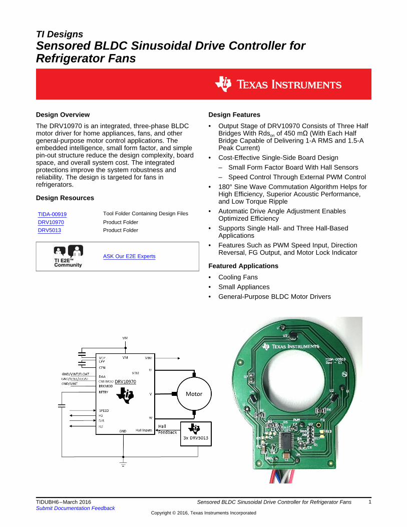
Design OverviewThe DRV10970 is an integrated, three-phase BLDCmotor driver for home appliances, fans, and othergeneral-purpose motor control applications. Theembedded intelligence, small form factor, and simplepin-out structure reduce the design complexity, boardspace, and overall system cost. The integratedprotections improve the system robustness andreliability. The design is targeted for fans inrefrigerators.
Design Resources
TIDA-00919 Tool Folder Containing Design FilesDRV10970 Product FolderDRV5013 Product Folder
ASK Our E2E Experts
Design Features• Output Stage of DRV10970 Consists of Three Half
Bridges With Rdson of 450 mΩ (With Each HalfBridge Capable of Delivering 1-A RMS and 1.5-APeak Current)
• Cost-Effective Single-Side Board Design– Small Form Factor Board With Hall Sensors– Speed Control Through External PWM Control
• 180° Sine Wave Commutation Algorithm Helps forHigh Efficiency, Superior Acoustic Performance,and Low Torque Ripple
• Automatic Drive Angle Adjustment EnablesOptimized Efficiency
• Supports Single Hall- and Three Hall-BasedApplications
• Features Such as PWM Speed Input, DirectionReversal, FG Output, and Motor Lock Indicator
Featured Applications• Cooling Fans• Small Appliances• General-Purpose BLDC Motor Drivers
Key System Specifications www.ti.com
2 TIDUBH6–March 2016Submit Documentation Feedback
Copyright © 2016, Texas Instruments Incorporated
Sensored BLDC Sinusoidal Drive Controller for Refrigerator Fans
An IMPORTANT NOTICE at the end of this TI reference design addresses authorized use, intellectual property matters and otherimportant disclaimers and information.
1 Key System SpecificationsA refrigerator is a very common household appliance which consists of a main compressor motor and amotor for a circulation fan. The circulation fan serves as a blower that rotates cold airflow throughout theunit to keep it cold. The fan for a refrigerator is typically a sensored brushless DC (BLDC) motor, whichrequires an electronic controller. The TIDA-00919 reference design is a ready platform for driving such afan motor.
This reference design is a cost-effective, small-form-factor, three-phase sinusoidal motor drive forsensored BLDC fan motors specified up to a maximum current of 1 A RMS at 18 V maximum. Unlike mostsensored drivers, the DRV10970 drives a motor with a 180° sinusoidal commutation, which results in lowtorque ripple, better acoustics, and a high drive efficiency. The speed input command can be utilized in theform of a pulse width modulation (PWM) input and a direction control by controlling a pin high or low.
Table 1 lists the key system specifications for the design.
Table 1. Key System Specifications
PARAMETER SPECIFICATIONDC input voltage 12 V
Rated power capacity 15 WSpeed input PWM
Operating ambient temperature –20°C to 50°CInverter efficiency ≥ 97% at rated load
Protections Overcurrent, overtemperature, and short circuit
The drive board has been designed for a small form factor in consideration of the small factors of theappliance fans. Because the motor driver has sensors, the printed-circuit board (PCB) is typically housedinside the motor, which explains the requirement for placing Hall sensors on the board. The low-costrequirement also confines the design to a single-side board.

www.ti.com System Description
3TIDUBH6–March 2016Submit Documentation Feedback
Copyright © 2016, Texas Instruments Incorporated
Sensored BLDC Sinusoidal Drive Controller for Refrigerator Fans
2 System DescriptionThe use of permanent-magnet brushless DC motors continue to gain prominence in the field because oftheir high efficiency, low maintenance, high reliability, low rotor inertia, and low noise as compared to thebrushed motor counterpart. A brushless permanent-magnet motor has a wound stator, which is apermanent magnet rotor assembly. These types of motors generally use internal or external devices tosense rotor position. The sensing devices provide logic signals for electronically switching the statorwindings in the proper sequence to maintain rotation of the magnet assembly.
The DRV10970 is an electronic drive which is used to sinusoidally control the drive of a sensored BLDCmotor. The system operates at 12-V power and provides the motor terminal outputs. The designimplements Hall sensors because the electronic components are placed inside the motor for mostsensored BLDC motors. The system also accepts user inputs such as direction and speed also in additionto providing some feedback, such as lock detection and speed feedback.
3 System Design TheoryThe DRV10970 device controls three-phase BLDC motors using a speed command (PWM), direction (FR)interface, and Hall signals from the motor. The device is capable of driving up to 1-A RMS and 1.5-A peakcurrent.
When the DRV10970 device powers up, it starts to drive the motor in trapezoidal communication modebased on Hall sensor information. If all three Hall sensors have been connected, the commutation logicrelies on all three Hall sensors. If a U-phase Hall sensor is the only sensor connected (VHP is floating),then the DRV10970 device starts to drive the motor in a single Hall sensor mode.
After six electrical cycles, the device switches to sinusoidal drive mode if the CMTMOD pin is not floating.If the motor has a 0° placement for the Hall sensor (set on the CMTMOD pin accordingly), the DRV10970device automatically adjusts the driving angle based on the feedback from the motor. The DRV10970device optimizes the efficiency regardless of the motor parameters and the load conditions.
This automatic function that drives the angle adjustment can be disabled by the DAA pin. A fixed drivingangle is available for the user to optimize the motor drive efficiency if this automatic function has beendisabled.
The PWM input duty cycle commands the steady-state motor speed, which converts to an average outputvoltage of VM multiplied by the duty cycle. A floating PWM pin functions as the full-speed command. TheFR input can be used to control the direction of motor rotations. The user can adjust the rotationaldirection while the motor is spinning. The device has a time delay (TLOCK_EX) before reversing direction.
The FG output is aligned with a U-phase Hall sensor signal, which indicates the motor speed. If the motorhas been locked by an external force for TLOCK_EN, then the RD output is asserted to indicate the motor lockcondition and DRV10970 retries after the TLOCK_EX period, which is determined by the capacitor on theRETRY pin.
When the motor is not spinning (either in lock condition or PWM = 0), the state of the phases are selectedby the BRKMOD pin. The phases can be maintained floating (coasting condition) or pulled down to GND(braking condition).
The DRV10970 device enters sleep mode when the PWM has been driven low for TSLEEP time and internalcircuits including regulators are turned off and the power consumption is less than 35 µA.
Overcurrent, current limit, thermal shutdown, and undervoltage protection circuits prevent systemcomponents from being damaged during extreme conditions.
OUT3
VCC1
GND2
U2
DRV5013ADQLPGM
OUT3
VCC1
GND2
U4
DRV5013ADQLPGM
OUT3
VCC1
GND2
U3
DRV5013ADQLPGM
GND
U_HP
W_HP
V_HP
10kR6
10kR8
10kR7
U_HN
W_HN
V_HN
W_HP
V_HP
U_HP
0.1µF
C3
0.1µF
C4
0.1µF
C5
VINT
DNP
DNP
DNP
System Design Theory www.ti.com
4 TIDUBH6–March 2016Submit Documentation Feedback
Copyright © 2016, Texas Instruments Incorporated
Sensored BLDC Sinusoidal Drive Controller for Refrigerator Fans
3.1 Single-Side DesignThe design targets the use of a single-side board because of the extremely cost-sensitive application.
With the constraint of a single-side board, the GND connection is routed to multiple places throughout theboard. To avoid the noise associated with ground loop on current sense and VINT, a provision has beenestablished to connect an optional resistor R13 of 0 Ω, which acts as a jumper if required.
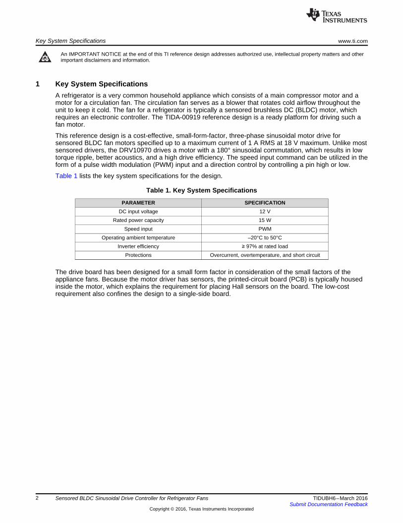
3.2 Hall Sensor ConnectionsHall sensors and their connections are very important parameters to consider while driving a sensoredBLDC motor. The DRV10970 device has been designed to work with Hall sensor elements as well as thelatched output types of Hall sensors. Apart from working with these sensor types, the DRV10970 alsoworks with different Hall sensor placements and with single hall mode and three-hall mode as well.
The TIDA-00919 design has three DRV5013 Hall sensors (U2, U3, and U4), which are of the single-ended, latch output type. The supply to the Hall sensors travels through VINT from the DRV10970 device,which is 5 V. Three Hall sensors are placed at 120° mechanical apart in the slot made for the rotor (seeFigure 1). Because the device has been designed to operate as differential input Hall sensor outputs, thedesign requires the creation of a reference point when being supplied with single-ended Hall sensoroutputs. This reference is created as VINT / 2 by a simple resistor divider formed by R3 and R5. Thisreference connects to all the negative terminals of the Hall sensor connections as Figure 2 shows.
Figure 1. TIDA-00919 Board Image Figure 2. Hall Sensor Connections
LOCK _EX 6 RETRYT 15.36 10 C= ´ ´
( )ILIM_ THR CL
LIMITCS
V AI
R
´=
BRKMOD CMTMOD
DAAVINTVINT
10k
R12
10k
R11
10k
R10
VINT
FR
10k
R9
www.ti.com System Design Theory
5TIDUBH6–March 2016Submit Documentation Feedback
Copyright © 2016, Texas Instruments Incorporated
Sensored BLDC Sinusoidal Drive Controller for Refrigerator Fans
The three capacitors C3, C4, and C5 filter the noise on the Hall sensor outputs. The Hall sensors aretypically located inside the motor; for this reason, the user can connect the Hall sensor outputs acrossthese capacitors if it is not feasible to mount the complete board inside the PCB. Take the appropriatelevel of care with the reference in this configuration. If using the board directly inside the motor and theHall sensors require mounting on the component side (the design is on the top side), the user must modifythe Hall sensor pinout.
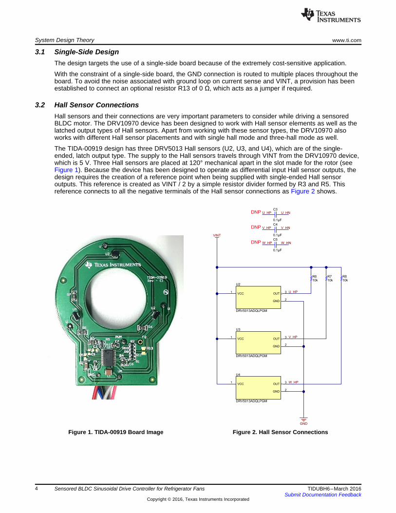
3.3 Hardware SettingsThe DRV10970 is capable of driving a BLDC motor in sinusoidal or trapezoidal way. The user can setother features by hardware, such as adaptive angle adjustment and brake mode adjustment. Configurethe required settings by making the appropriate placements of R9 to R12, as Table 2 details and Figure 3shows.
Table 2. Drive Settings
FUNCTION SETTINGS RESISTOR
Commutation modePlace R11 Sine drive with 30° Hall placement
Remove R11 Trapezoidal driveBrake mode Place R9 Coasting mode
Adaptive angle adjustPlace R12 10° drive angle adjustment
Remove R12 Auto-drive angle adjustmentDirection control Remove R10 Direction reversal
Figure 3. Hardware Settings
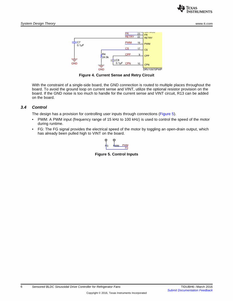
The current sense resistor helps to set the current limit during operation. The current sense resistor iscalculated by Equation 1 (refer to the datasheet for more details).
where• VILIM_THR = 1.2 V (typical)• ACL = 25000 A/A (typical) (1)
During a fault condition, the device stops the drive and attempts to drive the motor again after a certaintime. The capacitor CRETRY determines this retry time, which is controlled by the charging and dischargingof the cap with VRETRY_H (1.2 V) and VRETRY_L (0.6 V) and source and sink current at 10 uA typical(see Equation 2 and Figure 4).
where• TLOCK_EX is in seconds (2)
FG
PWMPWMFG
CPP9
CPN10
CS17
PWM19
RETRY22
FR23
DRV10970PWP
FRRETRY
PWM
CS
CPP
CPN
GND
GND 0.1µFC8
24.0kR4
0.1µFC7
System Design Theory www.ti.com
6 TIDUBH6–March 2016Submit Documentation Feedback
Copyright © 2016, Texas Instruments Incorporated
Sensored BLDC Sinusoidal Drive Controller for Refrigerator Fans
Figure 4. Current Sense and Retry Circuit
With the constraint of a single-side board, the GND connection is routed to multiple places throughout theboard. To avoid the ground loop on current sense and VINT, utilize the optional resistor provision on theboard. If the GND noise is too much to handle for the current sense and VINT circuit, R13 can be addedon the board.
3.4 ControlThe design has a provision for controlling user inputs through connections (Figure 5).• PWM: A PWM input (frequency range of 15 kHz to 100 kHz) is used to control the speed of the motor
during runtime.• FG: The FG signal provides the electrical speed of the motor by toggling an open-drain output, which
has already been pulled high to VINT on the board.
Figure 5. Control Inputs
www.ti.com Block Diagram
7TIDUBH6–March 2016Submit Documentation Feedback
Copyright © 2016, Texas Instruments Incorporated
Sensored BLDC Sinusoidal Drive Controller for Refrigerator Fans
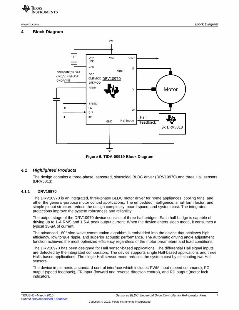
4 Block Diagram
Figure 6. TIDA-00919 Block Diagram
4.1 Highlighted ProductsThe design contains a three-phase, sensored, sinusoidal BLDC driver (DRV10970) and three Hall sensors(DRV5013).
4.1.1 DRV10970The DRV10970 is an integrated, three-phase BLDC motor driver for home appliances, cooling fans, andother the general-purpose motor control applications. The embedded intelligence, small form factor, andsimple pinout structure reduce the design complexity, board space, and system cost. The integratedprotections improve the system robustness and reliability.
The output stage of the DRV10970 device consists of three half bridges. Each half bridge is capable ofdriving up to 1-A RMS and 1.5-A peak output current. When the device enters sleep mode, it consumes atypical 35-μA of current.
The advanced 180° sine-wave commutation algorithm is embedded into the device that achieves highefficiency, low torque ripple, and superior acoustic performance. The automatic driving angle adjustmentfunction achieves the most optimized efficiency regardless of the motor parameters and load conditions.
The DRV10970 has been designed for Hall sensor-based applications. The differential Hall signal inputsare detected by the integrated comparators. The device supports single Hall-based applications and threeHalls-based applications. The single Hall sensor mode reduces the system cost by eliminating two Hallsensors.
The device implements a standard control interface which includes PWM input (speed command), FGoutput (speed feedback), FR input (forward and reverse direction control), and RD output (motor lockindicator).

Block Diagram www.ti.com
8 TIDUBH6–March 2016Submit Documentation Feedback
Copyright © 2016, Texas Instruments Incorporated
Sensored BLDC Sinusoidal Drive Controller for Refrigerator Fans
The DRV10970 supports both 30° and 0° Hall sensors (with respect to the corresponding phase back-electromotive force [BEMF]). The device implements a trapezoidal drive mode to address the higherpower requirement.
The DRV10970 device determines the motor lock condition based on the absence of hall input switching.The device re-attempts to spin the motor after an adjustable auto-retry time, which can be configured by acapacitor connected to the RETRY pin.
The device incorporates multiple protection features such as overcurrent, undervoltage, overtemperature,and locked rotor conditions to improve the system robustness.
The DRV10970 is packaged in a thermally enhanced 24-pin TSSOP package (eco-friendly: RoHS and noSb/Br).
4.1.2 DRV5013The DRV5013 device is a chopper-stabilized Hall effect sensor that offers a magnetic sensing solutionwith superior sensitivity stability over temperature and integrated protection features.
The magnetic field is indicated through a digital bipolar latch output. The integrated circuit (IC) has anopen-drain output stage with a 30-mA current sink capability. A wide operating voltage range from 2.5 V to38 V with reverse polarity protection up to –22 V makes the device suitable for a wide range of industrialapplications.
Internal protection functions have been provided for reverse supply conditions, load dump, and outputshort circuit or overcurrent.
Device features• Digital bipolar-latch Hall sensor• Superior temperature stability
– BOP ±10% overtemperature• High sensitivity options (BOP and BRP)
– +2.7 / –2.7 mT (AD)– +6 / –6 mT (AG)– +12 / –12 mT (BC)
• Supports a wide voltage range– 2.5 to 38 V– No external regulator required
• Wide operating temperature range– TA = –40 to 125°C (Q)
• Open-drain output (30-mA sink)• Fast 35-µs power-on time• Small package and footprint
– Surface mount 3-pin SOT-23 (DBZ)• 2.92 mm × 2.37 mm
– Throughhole 3-pin TO-92 (LPG)• 4.00 mm × 3.15 mm
• Protection features– Reverse supply protection (up to –22 V)– Supports up to 40-V load dump– Output short-circuit protection– Output current limitation
www.ti.com Getting Started
9TIDUBH6–March 2016Submit Documentation Feedback
Copyright © 2016, Texas Instruments Incorporated
Sensored BLDC Sinusoidal Drive Controller for Refrigerator Fans
5 Getting StartedThe hardware is capable of exploring all the available features of the DRV10970 device.
5.1 Hardware SettingsBefore connecting the motor to the board, the user must be aware of the Hall placement if the Hall signalsare being externally provided to the board. Configure the following required hardware settings beforegetting started with the hardware (see Table 2 as well).• CS: Check whether the onboard resistor is correct as per the expected motor current. Change this
resistor if required.• BRKMOD: Check R9 to confirm if either must be present for the appropriate brake mode.• CMTMOD: Check R11 for the appropriate commutation mode. A provision has been provided to either
pull the pin high or keep it floating.• DAA: The DAA settings can be changed while in three-Hall sensor mode by using R12.• Hall sensor: Depending on the type of Hall sensors and placement in the motor, connect the Hall
sensors (if they are being provided externally). Take note of the Hall sensor pinout, as thisconfiguration depends on the way that the PCB has been used inside the motor.
5.2 StartAfter having correctly implemented the hardware settings, connect the power supply to the board andmotor connected to U/V/W terminals on the board.
Switch on the power supply and apply the PWM input to the PWM jumper for speed control. The FGoutput shows the speed as an electrical frequency.
5.3 RuntimeChange the speed command through the PWM input and observe the speed feedback on the FG pin.
Test Setup www.ti.com
10 TIDUBH6–March 2016Submit Documentation Feedback
Copyright © 2016, Texas Instruments Incorporated
Sensored BLDC Sinusoidal Drive Controller for Refrigerator Fans
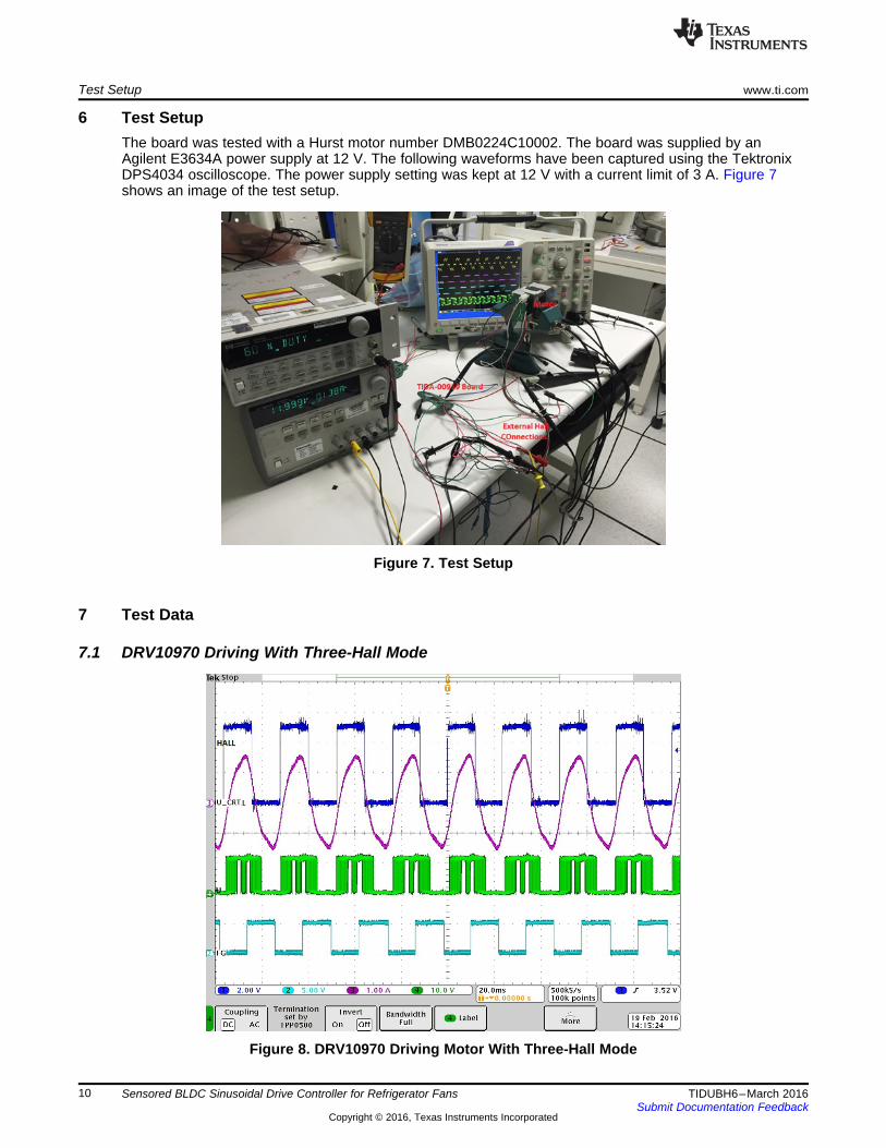
6 Test SetupThe board was tested with a Hurst motor number DMB0224C10002. The board was supplied by anAgilent E3634A power supply at 12 V. The following waveforms have been captured using the TektronixDPS4034 oscilloscope. The power supply setting was kept at 12 V with a current limit of 3 A. Figure 7shows an image of the test setup.
Figure 7. Test Setup
7 Test Data
7.1 DRV10970 Driving With Three-Hall Mode
Figure 8. DRV10970 Driving Motor With Three-Hall Mode
www.ti.com Test Data
11TIDUBH6–March 2016Submit Documentation Feedback
Copyright © 2016, Texas Instruments Incorporated
Sensored BLDC Sinusoidal Drive Controller for Refrigerator Fans
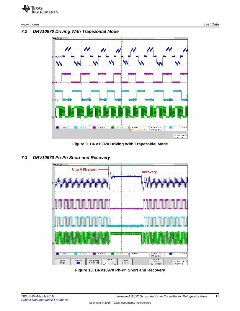
7.2 DRV10970 Driving With Trapezoidal Mode
Figure 9. DRV10970 Driving With Trapezoidal Mode
7.3 DRV10970 Ph-Ph Short and Recovery
Figure 10. DRV10970 Ph-Ph Short and Recovery

Test Data www.ti.com
12 TIDUBH6–March 2016Submit Documentation Feedback
Copyright © 2016, Texas Instruments Incorporated
Sensored BLDC Sinusoidal Drive Controller for Refrigerator Fans
7.4 Thermal Image at 18-V, 1-A Load
Figure 11. Thermal Image at 18-V, 1-A Load

www.ti.com Design Files
13TIDUBH6–March 2016Submit Documentation Feedback
Copyright © 2016, Texas Instruments Incorporated
Sensored BLDC Sinusoidal Drive Controller for Refrigerator Fans
8 Design Files
8.1 SchematicsTo download the schematics, see the design files at TIDA-00919.
8.2 Bill of MaterialsTo download the bill of materials (BOM), see the design files at TIDA-00919.
8.3 Layer PlotsTo download the layer plots, see the design files at TIDA-00919.
8.4 Altium ProjectTo download the Altium project files, see the design files at TIDA-00919.
8.5 Gerber FilesTo download the Gerber files, see the design files at TIDA-00919.
8.6 Assembly DrawingsTo download the assembly drawings, see the design files at TIDA-00919.
9 References
1. Texas Instruments, DRV10970 3-Phase Brushless DC Motor Driver, DRV10970 Datasheet (SLVSCU7)
10 TerminologyBEMF— Back-electromotive force
BLDC— Brushless DC motor
ESD— Electrostatic discharge
FET— Field-effect transistor
MOSFET— Metal-oxide-semiconductor field-effect transistor
PWM— Pulse width modulation
RMS— Root mean square
RPM— Rotations per minute
11 About the AuthorJASRAJ DALVI is an applications engineer at Texas Instruments, where he is responsible for developingreference design solutions and control algorithms for motor control applications. He completed hisBachelors of Engineering degree in Electrical Engineering from University of Pune, India and his PostGraduate Diploma in Marketing Management at S.I.B.M. in Pune, India.

IMPORTANT NOTICE FOR TI REFERENCE DESIGNS
Texas Instruments Incorporated ("TI") reference designs are solely intended to assist designers (“Buyers”) who are developing systems thatincorporate TI semiconductor products (also referred to herein as “components”). Buyer understands and agrees that Buyer remainsresponsible for using its independent analysis, evaluation and judgment in designing Buyer’s systems and products.TI reference designs have been created using standard laboratory conditions and engineering practices. TI has not conducted anytesting other than that specifically described in the published documentation for a particular reference design. TI may makecorrections, enhancements, improvements and other changes to its reference designs.Buyers are authorized to use TI reference designs with the TI component(s) identified in each particular reference design and to modify thereference design in the development of their end products. HOWEVER, NO OTHER LICENSE, EXPRESS OR IMPLIED, BY ESTOPPELOR OTHERWISE TO ANY OTHER TI INTELLECTUAL PROPERTY RIGHT, AND NO LICENSE TO ANY THIRD PARTY TECHNOLOGYOR INTELLECTUAL PROPERTY RIGHT, IS GRANTED HEREIN, including but not limited to any patent right, copyright, mask work right,or other intellectual property right relating to any combination, machine, or process in which TI components or services are used.Information published by TI regarding third-party products or services does not constitute a license to use such products or services, or awarranty or endorsement thereof. Use of such information may require a license from a third party under the patents or other intellectualproperty of the third party, or a license from TI under the patents or other intellectual property of TI.TI REFERENCE DESIGNS ARE PROVIDED "AS IS". TI MAKES NO WARRANTIES OR REPRESENTATIONS WITH REGARD TO THEREFERENCE DESIGNS OR USE OF THE REFERENCE DESIGNS, EXPRESS, IMPLIED OR STATUTORY, INCLUDING ACCURACY ORCOMPLETENESS. TI DISCLAIMS ANY WARRANTY OF TITLE AND ANY IMPLIED WARRANTIES OF MERCHANTABILITY, FITNESSFOR A PARTICULAR PURPOSE, QUIET ENJOYMENT, QUIET POSSESSION, AND NON-INFRINGEMENT OF ANY THIRD PARTYINTELLECTUAL PROPERTY RIGHTS WITH REGARD TO TI REFERENCE DESIGNS OR USE THEREOF. TI SHALL NOT BE LIABLEFOR AND SHALL NOT DEFEND OR INDEMNIFY BUYERS AGAINST ANY THIRD PARTY INFRINGEMENT CLAIM THAT RELATES TOOR IS BASED ON A COMBINATION OF COMPONENTS PROVIDED IN A TI REFERENCE DESIGN. IN NO EVENT SHALL TI BELIABLE FOR ANY ACTUAL, SPECIAL, INCIDENTAL, CONSEQUENTIAL OR INDIRECT DAMAGES, HOWEVER CAUSED, ON ANYTHEORY OF LIABILITY AND WHETHER OR NOT TI HAS BEEN ADVISED OF THE POSSIBILITY OF SUCH DAMAGES, ARISING INANY WAY OUT OF TI REFERENCE DESIGNS OR BUYER’S USE OF TI REFERENCE DESIGNS.TI reserves the right to make corrections, enhancements, improvements and other changes to its semiconductor products and services perJESD46, latest issue, and to discontinue any product or service per JESD48, latest issue. Buyers should obtain the latest relevantinformation before placing orders and should verify that such information is current and complete. All semiconductor products are soldsubject to TI’s terms and conditions of sale supplied at the time of order acknowledgment.TI warrants performance of its components to the specifications applicable at the time of sale, in accordance with the warranty in TI’s termsand conditions of sale of semiconductor products. Testing and other quality control techniques for TI components are used to the extent TIdeems necessary to support this warranty. Except where mandated by applicable law, testing of all parameters of each component is notnecessarily performed.TI assumes no liability for applications assistance or the design of Buyers’ products. Buyers are responsible for their products andapplications using TI components. To minimize the risks associated with Buyers’ products and applications, Buyers should provideadequate design and operating safeguards.Reproduction of significant portions of TI information in TI data books, data sheets or reference designs is permissible only if reproduction iswithout alteration and is accompanied by all associated warranties, conditions, limitations, and notices. TI is not responsible or liable forsuch altered documentation. Information of third parties may be subject to additional restrictions.Buyer acknowledges and agrees that it is solely responsible for compliance with all legal, regulatory and safety-related requirementsconcerning its products, and any use of TI components in its applications, notwithstanding any applications-related information or supportthat may be provided by TI. Buyer represents and agrees that it has all the necessary expertise to create and implement safeguards thatanticipate dangerous failures, monitor failures and their consequences, lessen the likelihood of dangerous failures and take appropriateremedial actions. Buyer will fully indemnify TI and its representatives against any damages arising out of the use of any TI components inBuyer’s safety-critical applications.In some cases, TI components may be promoted specifically to facilitate safety-related applications. With such components, TI’s goal is tohelp enable customers to design and create their own end-product solutions that meet applicable functional safety standards andrequirements. Nonetheless, such components are subject to these terms.No TI components are authorized for use in FDA Class III (or similar life-critical medical equipment) unless authorized officers of the partieshave executed an agreement specifically governing such use.Only those TI components that TI has specifically designated as military grade or “enhanced plastic” are designed and intended for use inmilitary/aerospace applications or environments. Buyer acknowledges and agrees that any military or aerospace use of TI components thathave not been so designated is solely at Buyer's risk, and Buyer is solely responsible for compliance with all legal and regulatoryrequirements in connection with such use.TI has specifically designated certain components as meeting ISO/TS16949 requirements, mainly for automotive use. In any case of use ofnon-designated products, TI will not be responsible for any failure to meet ISO/TS16949.IMPORTANT NOTICE
Mailing Address: Texas Instruments, Post Office Box 655303, Dallas, Texas 75265Copyright © 2016, Texas Instruments Incorporated
Related Documents