Communications Networking Protocols Professor Izhak Rubin Electrical Engineering Department UCLA [email protected] © 2014-2015 by Professor Izhak Rubin

Section 6 Networking Protocols
Dec 21, 2015
hw
Welcome message from author
This document is posted to help you gain knowledge. Please leave a comment to let me know what you think about it! Share it to your friends and learn new things together.
Transcript
Communications
Networking Protocols
Professor Izhak Rubin
Electrical Engineering Department
UCLA
© 2014-2015 by Professor Izhak Rubin
(c) Prof. Izhak Rubin 2
Layered Communications
Networking Protocol Structure
Each layer provides a well defined targeted service
Ordering: a layer provides a service to the layer above it and receives a service from the layer below it
Intelligent message operations/processing between layer-i peer entities

(c) Prof. Izhak Rubin 3
PDUs and SDUs
Protocol Data Unit (PDU) – a message unit as it is intelligently processed (and understood) by peer layer entities Layer i PDU is intelligently understood and processed by
layer i entities
Service Data Unit (SDU) – a message entities, accompanied by primitives (directives) that is transacted between neighboring layers Such transactions can involve an acknowledging
handshake
(c) Prof. Izhak Rubin 4
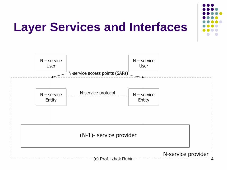
Layer Services and Interfaces
N-service provider
(N-1)- service provider
N – service Entity
N – service Entity
N – service User
N – service User
N-service access points (SAPs)
N-service protocol
(c) Prof. Izhak Rubin 5
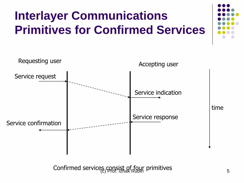
Interlayer Communications
Primitives for Confirmed Services
Requesting user Accepting user
Service request
Service confirmation
Service indication
Service response
time
Confirmed services consist of four primitives
(c) Prof. Izhak Rubin 6
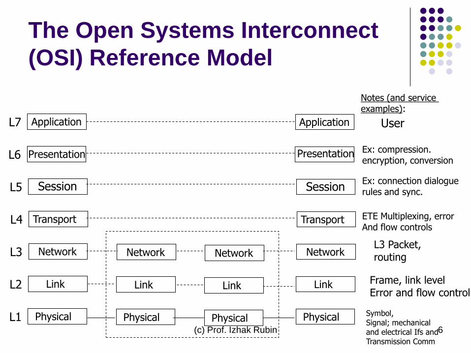
The Open Systems Interconnect
(OSI) Reference Model
Application L7
Presentation L6
Session L5
Transport L4
Network L3
Link L2
Physical L1
Application
Session
Transport
Network
Link
Physical
Presentation
Network
Link
Physical
Network
Link
Physical
L3 Packet, routing
Frame, link level Error and flow control
Symbol, Signal; mechanical and electrical Ifs and Transmission Comm
User
Ex: compression. encryption, conversion
Notes (and service examples):
ETE Multiplexing, error And flow controls
Ex: connection dialogue rules and sync.

(c) Prof. Izhak Rubin 7
Layer 7: Application layer
The application layer is the seventh level of the seven-layer OSI model. It interfaces directly to and performs common application services for the application processes; it also issues requests to the presentation layer. Note carefully that this layer provides services to user-defined application processes, and not to the end user. For example, it defines a file transfer protocol, but the end user must go through an application process to invoke file transfer. The OSI model does not include human interfaces.
The common application services sublayer provides functional elements including the Remote Operations Service Element (comparable to Internet Remote Procedure Call), Association Control, and Transaction Processing (according to the ACID requirements).
Above the common application service sublayer are functions meaningful to user application programs, such as messaging (X.400), directory (X.500), file transfer (FTAM), virtual terminal (VTAM), and batch job manipulation (JTAM).
(c) Prof. Izhak Rubin 8
Layer 6: Presentation layer
The Presentation layer transforms the data to provide a standard interface for the Application layer. MIME encoding, data encryption and similar manipulation of the presentation are done at this layer to present the data as a service or protocol developer sees fit. Examples of this layer are converting an EBCDIC-coded text file to an ASCII-coded file, or serializing objects and other data structures into and out of XML.

(c) Prof. Izhak Rubin 9
Layer 5: Session layer
The Session layer controls the dialogues/connections (sessions) between computers. It establishes, manages and terminates the connections between the local and remote application. It provides for either full-duplex or half-duplex operation, and establishes checkpointing, adjournment, termination, and restart procedures. The OSI model made this layer responsible for "graceful close" of sessions, which is a property of TCP, and also for session checkpointing and recovery, which is not usually used in the Internet protocols suite.
(c) Prof. Izhak Rubin 10
Layer 4: Transport layer
The Transport layer provides transparent transfer of data between end users, providing reliable data transfer services to the upper layers.
The transport layer controls the reliability of a given link through flow control, segmentation/desegmentation, and error control.
Some protocols are state and connection oriented. This means that the transport layer can keep track of the segments and retransmit those that fail.
(c) Prof. Izhak Rubin 11
Transport layer (Cont.)
The best known example of a layer 4 protocol is the Transmission Control Protocol (TCP).
The transport layer is the layer that converts messages into TCP segments or User Datagram Protocol (UDP), Stream Control Transmission Protocol (SCTP), etc. packets.
Perhaps an easy way to visualize the Transport Layer is to compare it with a Post Office, which deals with the dispatch and classification of mail and parcels sent.
(c) Prof. Izhak Rubin 12
Transport layer (Cont.)
Do remember, however, that a post office
manages the outer envelope of mail. Higher
layers may have the equivalent of double
envelopes, such as cryptographic Presentation
services that can be read by the addressee only.
Roughly speaking, tunneling protocols operate at
the transport layer, such as carrying non-IP
protocols such as IBM's SNA or Novell's IPX over an
IP network, or end-to-end encryption with IPsec.
(c) Prof. Izhak Rubin 13
Layer 3: Network layer
The Network layer provides the functional and procedural means of transferring variable length data sequences from a source to a destination via one or more networks while maintaining the quality of service requested by the Transport layer.
The Network layer performs network routing functions, and might also perform fragmentation and reassembly, and report delivery errors.
Routers operate at this layer—sending data throughout the extended network and making the Internet possible.
(c) Prof. Izhak Rubin 14
Network layer (Cont.)
This is a logical addressing scheme – values are chosen by the network engineer.
The addressing scheme is hierarchical.
The best known example of a layer 3 protocol is the Internet Protocol (IP).
Perhaps it's easier to visualize this layer as managing the sequence of human carriers taking a letter from the sender to the local post office, trucks that carry sacks of mail to other post offices or airports, airplanes that carry airmail between major cities, trucks that distribute mail sacks in a city, and carriers that take a letter to its destinations.
Think of fragmentation as splitting a large document into smaller envelopes for shipping, or, in the case of the network layer, splitting an application or transport record into packets.
(c) Prof. Izhak Rubin 15
Layer 2: Data Link layer
The Data Link layer provides the functional and procedural means to transfer data between network entities and to detect and possibly correct errors that may occur in the Physical layer.
The best known example of this is Ethernet.
This layer manages the interaction of devices with a shared medium. (MAC sub-layer)
Other examples of data link protocols are HDLC and ADCCP for point-to-point or packet-switched networks and Aloha for local area networks.

(c) Prof. Izhak Rubin 16
Data Link layer (Cont.)
On IEEE 802 local area networks, and some non-IEEE 802 networks such as FDDI, this layer may be split into a Media Access Control (MAC) layer and the IEEE 802.2 Logical Link Control (LLC) layer.
It arranges bits from the physical layer into logical chunks of data, known as frames.

(c) Prof. Izhak Rubin 17
Data Link layer (Cont.)
This is the layer at which the bridges
and switches operate.
Connectivity is provided only among
locally attached network nodes
forming layer 2 domains for unicast or
broadcast forwarding.
(c) Prof. Izhak Rubin 18
Data Link layer (Cont.)
The data link layer might implement a sliding window flow control and acknowledgment mechanism to provide reliable delivery of frames;
that is the case for SDLC and HDLC, and derivatives of HDLC such as LAPB and LAPD.
Only error detection, not flow control using sliding window, is present in modern data link protocols such as Point-to-Point Protocol (PPP),
On local area networks, the IEEE 802.2 LLC layer is often not used for most protocols on Ethernet, and, on other local area networks, its flow control and acknowledgment mechanisms are rarely used.
Sliding window flow control and acknowledgment is used at the transport layers by protocols such as TCP.
(c) Prof. Izhak Rubin 19
Layer 1: Physical layer
The Physical layer defines all the electrical and physical specifications for devices.
In particular, it defines the relationship between a device and a physical medium.
This includes the layout of pins, voltages, and cable specifications.
Hubs, repeaters, network adapters and Host Bus Adapters (HBAs used in Storage Area Networks) are physical-layer devices.
(c) Prof. Izhak Rubin 20
Physical layer (Cont.)
To understand the function of the physical layer in contrast to the functions of the data link layer, think of the physical layer as concerned primarily with the interaction of a single device with a medium, where the data link layer is concerned more with the interactions of multiple devices (i.e., at least two) with a shared medium.
The physical layer will tell one device how to transmit to the medium, and another device how to receive from it, but not, with modern protocols, how to gain access to the medium.
Older physical layer standards such as RS-232 do use physical wires to control access to the medium.
(c) Prof. Izhak Rubin 21
Physical layer (Cont.)
The major functions and services performed by the physical layer are:
* Establishment and termination of a connection to a communications medium.
* Participation in the process whereby the communication resources are effectively shared among multiple users. For example, contention resolution and flow control.
* Modulation, or conversion between the representation of digital data in user equipment and the corresponding signals transmitted over a communications channel. These are signals operating over the physical cabling (such as copper and fiber optic) or over a radio link.
(c) Prof. Izhak Rubin 22
Physical layer (Cont.)
Parallel SCSI buses operate in this layer, although it must be remembered that the logical SCSI protocol is a transport-layer protocol that runs over this bus.
Ethernet incorporates both this layer and the data-link layer.
The same applies to other local-area networks, such as Token ring, FDDI, and IEEE 802.11, as well as personal area networks such as Bluetooth.
(c) Prof. Izhak Rubin 23
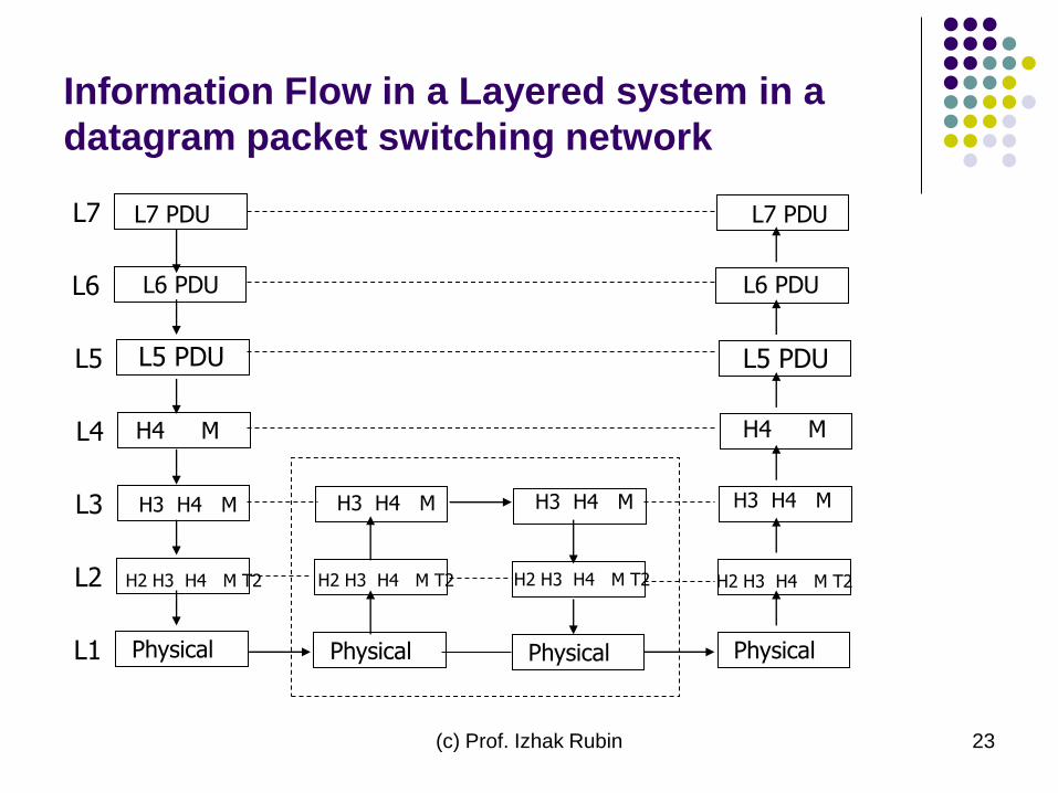
Information Flow in a Layered system in a
datagram packet switching network
L7 PDU L7
L6 PDU L6
L5 PDU L5
H4 M L4
H3 H4 M L3
H2 H3 H4 M T2
L2
Physical L1 Physical
H2 H3 H4 M T2
Physical Physical
H2 H3 H4 M T2
H2 H3 H4 M T2
H3 H4 M H3 H4 M H3 H4 M
H4 M
L5 PDU
L6 PDU
L7 PDU
(c) Prof. Izhak Rubin 24
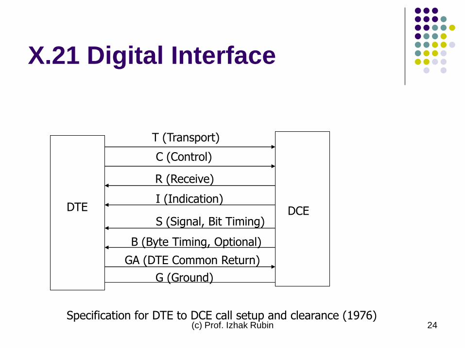
X.21 Digital Interface
DTE DCE
T (Transport)
C (Control)
R (Receive)
I (Indication)
S (Signal, Bit Timing)
B (Byte Timing, Optional)
GA (DTE Common Return)
G (Ground)
Specification for DTE to DCE call setup and clearance (1976)
(c) Prof. Izhak Rubin 25
Data Link Control Protocols
Link layer communications
Typical services: SAP, Error control, flow control, sequencing
Protocol types:
Asynchronous (e.g., teletype, RS232C)
Synchronous character oriented (e.g., BSC)
Synchronous bit oriented (e.g., SDLC, HDLC, X.25, LAP, LAPB and other)
(c) Prof. Izhak Rubin 26
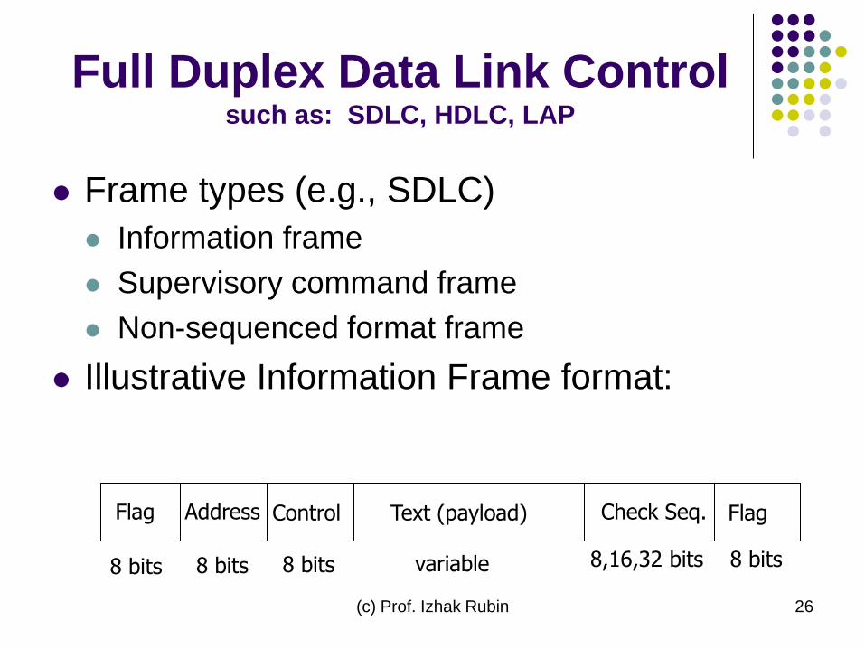
Full Duplex Data Link Control such as: SDLC, HDLC, LAP
Frame types (e.g., SDLC)
Information frame
Supervisory command frame
Non-sequenced format frame
Illustrative Information Frame format:
Flag Address Control Text (payload) Check Seq. Flag
8 bits 8 bits 8 bits variable 8,16,32 bits 8 bits
(c) Prof. Izhak Rubin 27
DLCP: Control Field
ARQ (Go Back N) Error control oriented
control field:
Send count (3 bits) = sequence number for
sent frame
Receive count (3 bits) = sequence number
of next frame expected to receive
Piggyback batch ACK
(c) Prof. Izhak Rubin 28
Network Layer Services:
Datagram vs. Virtual Circuit
Initial Setup:
Datagram: None
VCS: Employed
Destination address:
Datagram: Required in every packet
VCS: used during connection setup phase
Error handling:
Datagram: Performed by host
VCS: Performed by network; transparent to host
(c) Prof. Izhak Rubin 29
Datagram vs. Virtual Circuit
(Cont.)
End-to-end flow control:
Datagram: Not provided by network
VCS: Provided by network
Packet Sequencing:
Datagram: messages passed to host in order of
arrival
VCS: messages delivered to host in order sent
(c) Prof. Izhak Rubin 30
Datagram vs. Virtual Circuit
(Cont.)
Datagram service features: rapidly adaptive
dynamic inter-networking across multiple
sub-network types; fast packet re-routing in
reacting to changes
VCS features: traffic engineering, QoS
guarantees to flows across connections,
dynamic network management through flow
admission control
(c) Prof. Izhak Rubin 31
X.25 DTE-DCE Interface
X.25: DTE-DCE interface with public packet switching networks
Specifications at layers 1, 2 and 3
Principal layer 3 service: Virtual circuit switching
Signaling system for establishment of Logical Channel connections (LCI)
Secondary service: fast select datagram.

(c) Prof. Izhak Rubin 32
X.25 PDUs
Flag ADDR Control Data Packet FSC Flag
N(R) P N(S) Q
Q D 0 1 LCGN LCN P(R) M P(S) Q DATA
Data Packet Seq. #
Data Packet Authorization
DLC Frame
DATA PACKET
(c) Prof. Izhak Rubin 33
X.25: Signaling
Connection establishment phase: Call request packet (at calling DTE/DCE interface)
Incoming call packet (at called DTE/DCE interface)
Call accepted packet (at called DTE/DCE interface)
Call connected packet (at calling DTE/DCE interface)
Disconnect phase: Clear request packet (at interface A)
Clear indication packet (at interface B)
Clear confirmation packet (at interface B)
Clear confirmation packet (at interface A)
(c) Prof. Izhak Rubin 34
Call Request Packet
Call request packet fields include:
Logical channel ID
Type = call request
Calling DTE Address Length
Called DTE Address Length
DTE Address
Facility field length
Facility field
User data
Local Area Networks

(c) Prof. Izhak Rubin 36
Features
Single organization
Broadband communications
Initially: data based
Simplified switching and routing based on topological layout regularity
Star topology
Central switch; switched Ethernet; shared medium switch (backend bus system); shared memory; space switching
Bus medium and topology; passive connection to shared medium; physical layer broadcast
Ring medium; active RIU insertions; point-to-point connections of RIUs
(c) Prof. Izhak Rubin 37
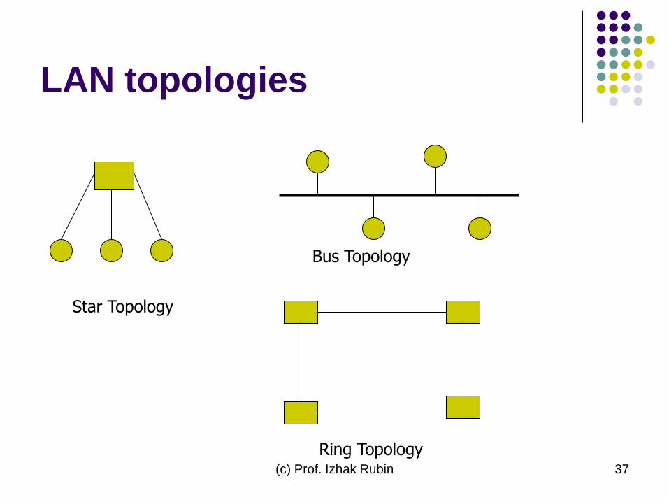
LAN topologies
Star Topology
Bus Topology
Ring Topology
(c) Prof. Izhak Rubin 38
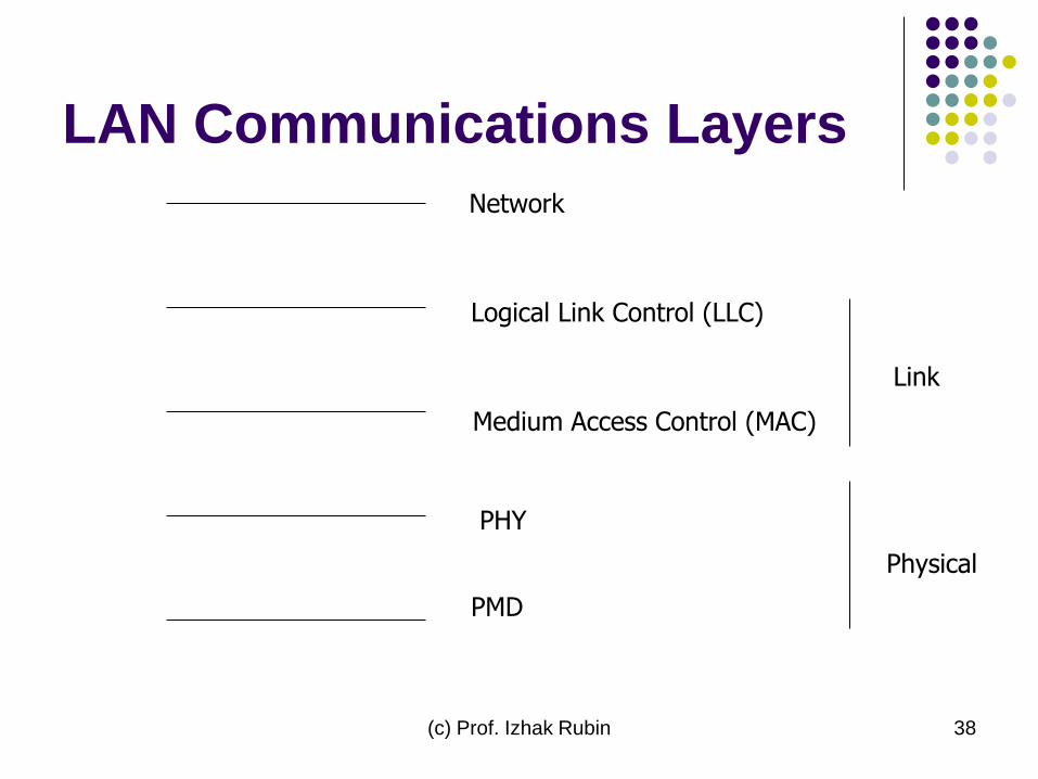
LAN Communications Layers
Network
Logical Link Control (LLC)
Medium Access Control (MAC)
PHY
PMD
Link
Physical

(c) Prof. Izhak Rubin 39
Ethernet Frame
(c) Prof. Izhak Rubin 40
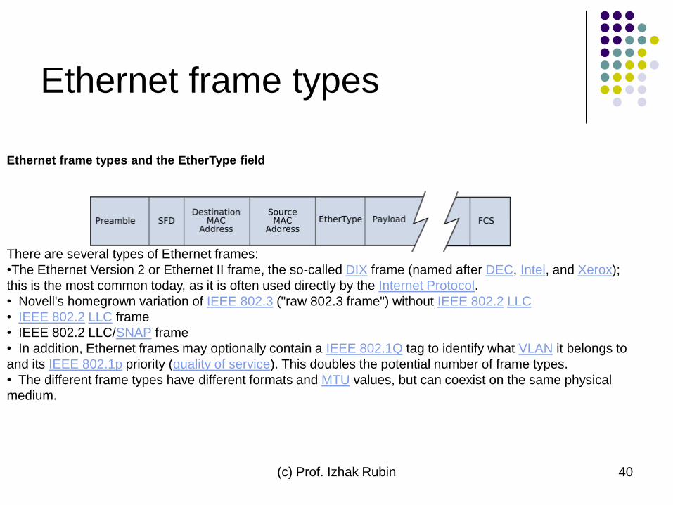
Ethernet frame types
Ethernet frame types and the EtherType field
There are several types of Ethernet frames:
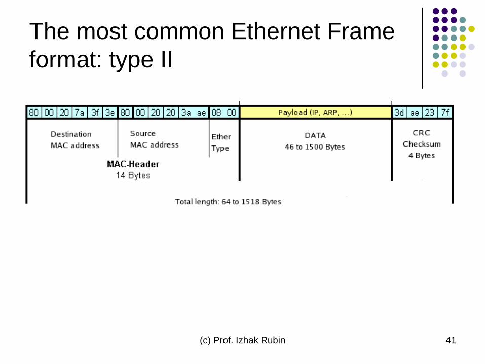
•The Ethernet Version 2 or Ethernet II frame, the so-called DIX frame (named after DEC, Intel, and Xerox);
this is the most common today, as it is often used directly by the Internet Protocol.
• Novell's homegrown variation of IEEE 802.3 ("raw 802.3 frame") without IEEE 802.2 LLC
• IEEE 802.2 LLC frame
• IEEE 802.2 LLC/SNAP frame
• In addition, Ethernet frames may optionally contain a IEEE 802.1Q tag to identify what VLAN it belongs to
and its IEEE 802.1p priority (quality of service). This doubles the potential number of frame types.
• The different frame types have different formats and MTU values, but can coexist on the same physical
medium.
(c) Prof. Izhak Rubin 41
The most common Ethernet Frame
format: type II

(c) Prof. Izhak Rubin 42
Internet Architecture and
Protocols
IEEE 802.2, PPP, LAPB, Ethernet, RS232, 802.3, 802.5 Physical/
Link Layer
ARP IP RARP
Type Code
Internet
Layer
Transport
Layer
Upper
Layer
Protocol Number
IGPs
(OSPF)
EGP TCP UDP ICMP IGMP
BGP RIP Port Number
TELNET, FTP, TFTP, BOOTP, HTTP, SNMP, SMTP
(c) Prof. Izhak Rubin 43
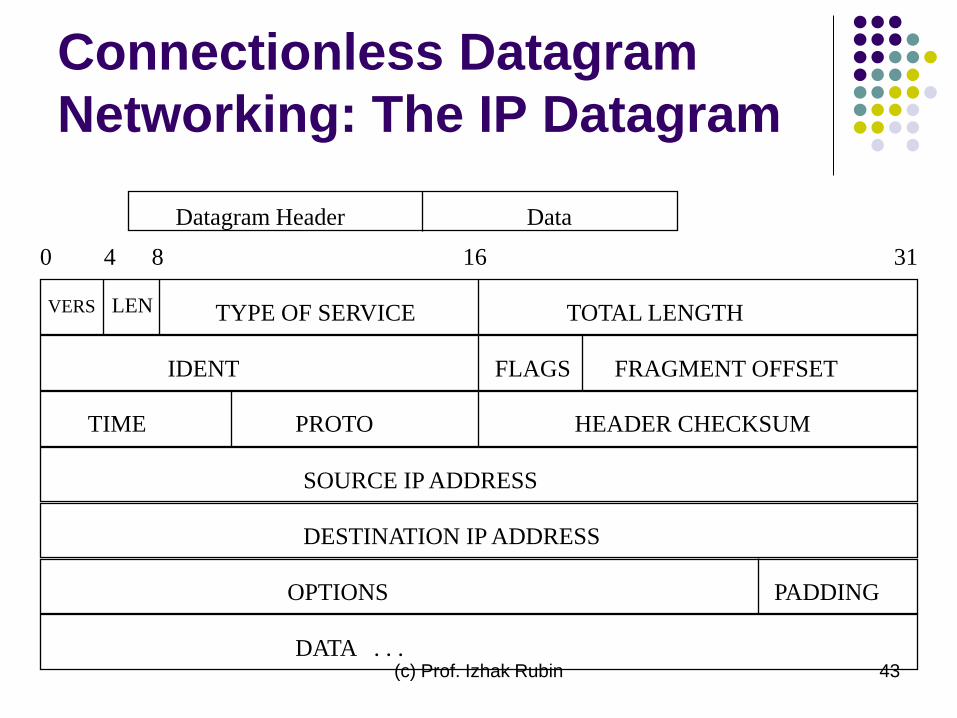
Connectionless Datagram
Networking: The IP Datagram
Datagram Header Data
0 4 8 16 31
VERS LEN TYPE OF SERVICE TOTAL LENGTH
IDENT FLAGS FRAGMENT OFFSET
TIME PROTO HEADER CHECKSUM
SOURCE IP ADDRESS
DESTINATION IP ADDRESS
OPTIONS PADDING
DATA . . .
(c) Prof. Izhak Rubin 44
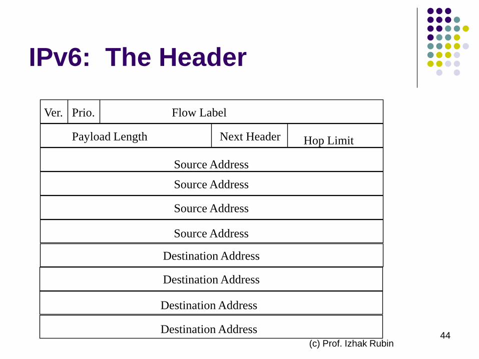
IPv6: The Header
Ver. Prio. Flow Label
Payload Length Next Header Hop Limit
Source Address
Source Address
Source Address
Destination Address
Destination Address
Destination Address
Destination Address
Source Address
(c) Prof. Izhak Rubin 45
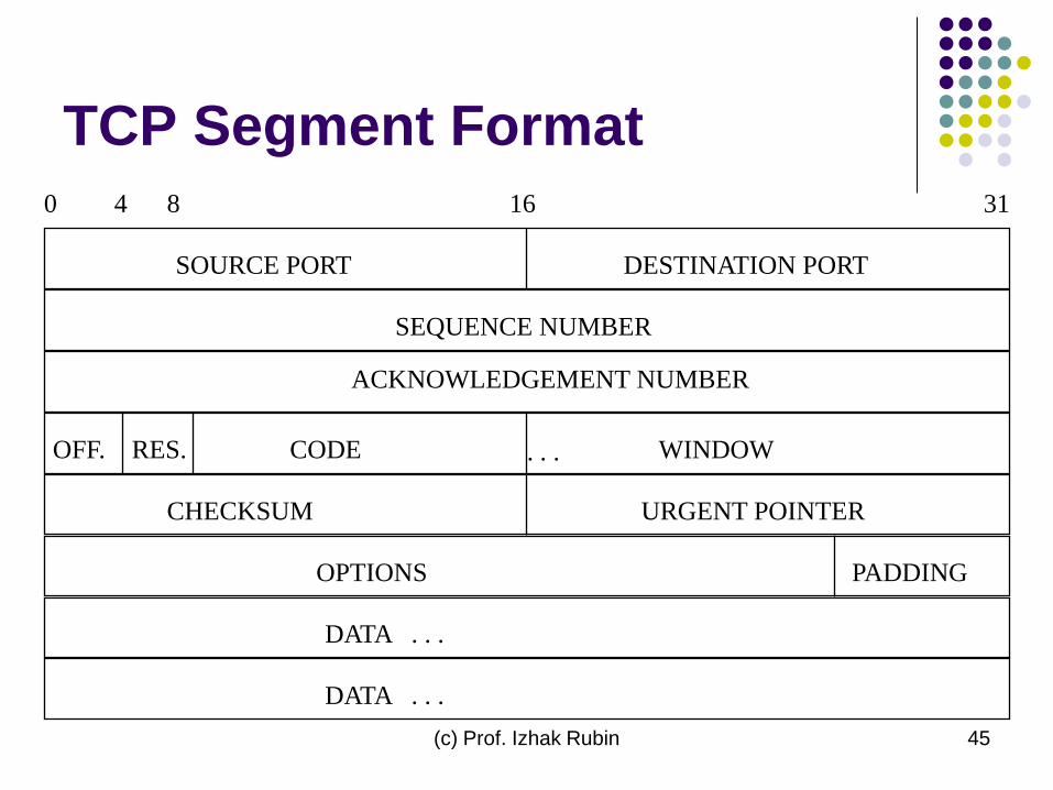
TCP Segment Format
0 4 8 16 31
SOURCE PORT DESTINATION PORT
OPTIONS PADDING
DATA . . .
. . .
DATA . . .
SEQUENCE NUMBER
ACKNOWLEDGEMENT NUMBER
OFF. RES. CODE WINDOW
CHECKSUM URGENT POINTER
Related Documents