Wavetek Wandel Goltermann Communications Test Solutions Wavetek Wandel Goltermann Please ask for : Vol. 3 Pocket Guide SONET Fundamentals and SONET Testing Vol. 2 Pocket Guide GSM Fundamentals in Mobile Radio Networks Vol. 4 Pocket Guide ATM Fundamentals and ATM testing Vol. 5 Pocket Guide E1 The World of E1 Subject to change without notice Nominal charge US $ 10 – TP/EN/PG01/0400/AE repl. 1006 Wavetek Wandel Goltermann Communications Test Solutions VOL. 1 SDH Pocket Guide revised version

Sdh Pocket Guide English
Dec 29, 2015
Welcome message from author
This document is posted to help you gain knowledge. Please leave a comment to let me know what you think about it! Share it to your friends and learn new things together.
Transcript

WavetekWandelGoltermannCommunications Test Solutions
Wavetek Wandel Goltermann
Please ask for :
Vol. 3
Pocket GuideSONETFundamentalsand SONET Testing
Vol. 2
Pocket GuideGSMFundamentals inMobile Radio Networks
Vol. 4
Pocket GuideATMFundamentals andATM testing
Vol. 5
Pocket GuideE1The World of E1
Subject to change without notice
Nominal charge US $ 10 ± TP/EN/PG01/0400/AE repl. 1006
WavetekWandelGoltermannCommunications Test Solutions
VOL. 1
SDHPocket Guide
revised version
Wavetek Wandel Goltermannis ITU-T sector member.
Pocket Guide to Synchronous Communications Systems
Publisher : Wavetek Wandel GoltermannEningen GmbH & Co.Marketing InternationalPostfach 12 6272795 Eningen u. A.GermanyE-mail: [email protected]://www.wwgsolutions.com
Author : Stephan Schultz
Contents
Introduction 1What is the situation in the ªsynchronousº market? 4Why SDH? 6The synchronous digital hierarchie in terms of a layer model 10What are the components of a synchronous network? 12The STM-1 frame format 16How are PDH and ATM signals transported by SDH? 20What is the difference between SDH and SONET? 23Pointer procedures 26AU-4 contiguous concatenation 30AU-4 virtual concatenation 32Transmission at higher hierarchy levels 33Error and alarm monitoring 34Automatic protection switching 39Synchronization 44TMN in the SDH network 47SDH measurement tasks 50
Sensor tests 52APS time measurement 53Performance analysis 55Tandem Connection Monitoring 58Jitter measurements 59
Overview of current ITU-T Recommendations 64Abbreviations 67

The sun is madeof copper . . .
Anyone making a statement like that these days would likely be con-sidered as quite mad, yet with these words, spoken back in 1861,Johann Philipp Reis began something that has completely changed theworld. This meaningless message, just spoken by Reis into his newinvention, was clearly heard by the receiver. The telephone was born.Despite this, the first usable telephone (A.G. Bell, 1876: Patent forelectrical and magnetic transmission of sounds) was thought of as littlemore than a toy.
Today, it would be difficult for us to imagine life without the telephone.World-wide, there are some 750 million telephone connections in useand the number of Internet users has exploded in the last few years.By the year 2000, according to a forecast from Nortel, there will bealmost 475 million Internet users and the number of services providedwill also grow rapidly.
Right from the start, network providers have been faced with copingwith a steadily increasing number of users and thus of telephone traffic.This led to the development of various methods and technologies, de-signed on the one hand to meet the market needs and on the otherhand to be as economical as possible. In the field of communicationsengineering, this resulted in the introduction of frequency division multi-plex (FDM) systems which enabled several telephone connections to betransmitted over a single cable. The idea was to modulate each tele-phone channel with a different carrier frequency to shift the signals intodifferent frequency ranges.
1
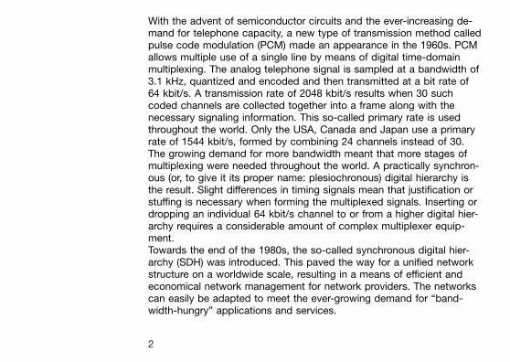
With the advent of semiconductor circuits and the ever-increasing de-mand for telephone capacity, a new type of transmission method calledpulse code modulation (PCM) made an appearance in the 1960s. PCMallows multiple use of a single line by means of digital time-domainmultiplexing. The analog telephone signal is sampled at a bandwidth of3.1 kHz, quantized and encoded and then transmitted at a bit rate of64 kbit/s. A transmission rate of 2048 kbit/s results when 30 suchcoded channels are collected together into a frame along with thenecessary signaling information. This so-called primary rate is usedthroughout the world. Only the USA, Canada and Japan use a primaryrate of 1544 kbit/s, formed by combining 24 channels instead of 30.The growing demand for more bandwidth meant that more stages ofmultiplexing were needed throughout the world. A practically synchron-ous (or, to give it its proper name: plesiochronous) digital hierarchy isthe result. Slight differences in timing signals mean that justification orstuffing is necessary when forming the multiplexed signals. Inserting ordropping an individual 64 kbit/s channel to or from a higher digital hier-archy requires a considerable amount of complex multiplexer equip-ment.Towards the end of the 1980s, the so-called synchronous digital hier-archy (SDH) was introduced. This paved the way for a unified networkstructure on a worldwide scale, resulting in a means of efficient andeconomical network management for network providers. The networkscan easily be adapted to meet the ever-growing demand for ªband-width-hungryº applications and services.
2
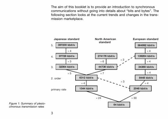
The aim of this booklet is to provide an introduction to synchronouscommunications without going into details about ªbits and bytesº. Thefollowing section looks at the current trends and changes in the trans-mission marketplace.
Figure 1: Summary of plesio-chronous transmission rates
Japanese standard North American European standardstandard
5.
64 64
4.
63 6663
64
3.
65 67 64
2. order
6463
64
primary rate
624 630
3

What is thesituation in theªsynchronousºmarket?
Seen as a whole, the transmission market is in a growth period. Predic-tions are for an average global growth rate of around 5.5%. There are,however, vast regional differences. Growth in Western Europe isexpected to be zero, but growth in Central and Eastern Europe is esti-mated at up to 22 %.
Figure 2: Global developmentin the market for synchronouscommunications(Source: Dataquest, 1997)
Western Europe
Central & E. Europe
United States
Rest of N. America
Latin Amerika
Africa
Japan
Four Tigers
Rest of Asia
Australasia
Worldwide
% growth from 1996±2000
4
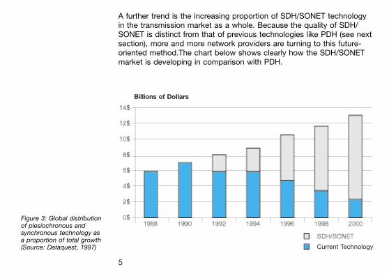
A further trend is the increasing proportion of SDH/SONET technologyin the transmission market as a whole. Because the quality of SDH/SONET is distinct from that of previous technologies like PDH (see nextsection), more and more network providers are turning to this future-oriented method.The chart below shows clearly how the SDH/SONETmarket is developing in comparison with PDH.
Figure 3: Global distributionof plesiochronous andsynchronous technology asa proportion of total growth(Source: Dataquest, 1997)
Billions of Dollars
Current Technology
5
Why SDH? With the introduction of PCM technology in the 1960s, communicationsnetworks were gradually converted to digital technology over the nextfew years. To cope with the demand for ever higher bit rates, a multiplexhierarchy called the plesiochronous digital hierarchy (PDH) evolved. Thebit rates start with the basic multiplex rate of 2 Mbit/s with further stagesof 8, 34 and 140 Mbit/s. In North America and Japan, the primary rate is1.5 Mbit/s. Hierarchy stages of 6 and 44 Mbit/s developed from this.Because of these very different developments, gateways between onenetwork and another were very difficult and expensive to realize.The 1980s saw a start in the development of the synchronous digitalhierarchy (SDH), with the intention of eliminating the disadvantagesinherent in PDH. SDH brings the following advantages to network pro-viders:
1. High transmission ratesTransmission rates of up to 10 Gbit/s can be achieved in modernSDH systems. SDH is therefore the most suitable technology forbackbones, which can be considered as being the super highways intoday's telecommunications networks.
2. Simplified add & drop functionCompared with the older PDH system, it is much easier to extractand insert low-bit rate channels from or into the high-speed bitstreams in SDH. It is no longer necessary to demultiplex and thenremultiplex the plesiochronous structure, a complex and costly pro-cedure at the best of times.
6
3. High availability and capacity matchingWith SDH, network providers can react quickly and easily to the re-quirements of their customers. For example, leased lines can beswitched in a matter of minutes. The network provider can use stan-dardized network elements that can be controlled and monitoredfrom a central location by means of a telecommunications networkmanagement (TMN) system.
4. ReliabilityModern SDH networks include various automatic back-up and repairmechanisms to cope with system faults. Failure of a link or a networkelement does not lead to failure of the entire network which could bea financial disaster for the network provider.These back-up circuits are also monitored by a management system.
5. Future-proof platform for new servicesRight now, SDH is the ideal platform for services ranging from POTS,ISDN and mobile radio through to data communications (LAN, WAN,etc.), and it is able to handle the very latest services, such as videoon demand and digital video broadcasting via ATM that are graduallybecoming established.
7
6. InterconnectionSDH makes it much easier to set up gateways between different net-work providers and to SONET systems. The SDH interfaces are glo-bally standardized, making it possible to combine network elementsfrom different manufacturers into a network. The result is a reductionin equipment costs as compared with PDH.
The driving force behind these developments is the growing demandfor more bandwidth, better quality of service and reliability, coupled withthe need to keep costs down in the face of increasing competition.
What about the future of transport networks? The trend is towards everhigher bit rates, such as STM-64 (time division multiplex, TDM). Thecurrent very high costs of such network elements are a retarding factor,though. The alternative is so-called dense wavelength division multi-plexing (DWDM). This is a technology that makes multiple use ofsingle-mode optical fibers possible. Various wavelengths are used ascarriers for the digital signals and are transmitted through the fiberssimultaneously. Currently-available systems permit transmission of16 wavelengths between 1520 nm and 1580 nm over a single fiber.One STM-16 channel is transmitted at each wavelength, giving a ca-pacity of some 40 Gbit/s per fiber. Expansion to 32 and even 64 wave-lengths has already been announced.Connected with the introduction of DWDM is the trend towards the ªall-optical networkº. Optical add/drop mulitplexers are already availablecommercially and the first field trials are in progress for optical cross-
8
connects. In terms of the ISO-OSI layer model, this development basi-cally means the introduction of an additional DWDM layer below theSDH layer (see figure 4). The future will therefore likely combine highermultiplex rates with the use of DWDM.
9

The synchronousdigital hierarchy interms of a layermodel
Telecommunications technologies are generally explained using so-called layer models. SDH can also be depicted in this way.
SDH networks are subdivided into various layers that are directly re-lated to the network topology. The lowest layer is the physical layer,which represents the transmission medium. This is usually a glass fiberor possibly a radio-link or satellite link. The regenerator section is thepath between regenerators. Part of the overhead (RSOH, regeneratorsection overhead) is available for the signaling required within this layer.
The remainder of the overhead (MSOH, multiplex section overhead) isused for the needs of the multiplex section. The multiplex sectioncovers the part of the SDH link between multiplexers. The carriers (VC,virtual containers) are available as payload at the two ends of this sec-tion.
The two VC layers represent a part of the mapping process. Mapping isthe procedure whereby the tributary signals, such as PDH and ATM sig-nals are packed into the SDH transport modules. VC-4 mapping is usedfor 140 Mbit/s or ATM signals and VC-12 mapping is used for 2 Mbit/ssignals.
10
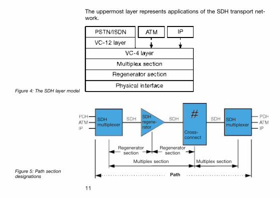
The uppermost layer represents applications of the SDH transport net-work.
Figure 4: The SDH layer model
Figure 5: Path sectiondesignations
SDHmultiplexer
SDHregene-rator
Cross-connect
SDHmultiplexer
Regeneratorsection
Regeneratorsection
Multiplex section Multiplex section
Path
11
What arethe componentsof a synchronousnetwork?
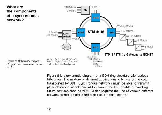
Figure 6: Schematic diagramof hybrid communications net-works
Figure 6 is a schematic diagram of a SDH ring structure with varioustributaries. The mixture of different applications is typical of the datatransported by SDH. Synchronous networks must be able to transmitplesiochronous signals and at the same time be capable of handlingfuture services such as ATM. All this requires the use of various differentnetwork elements; these are discussed in this section.
STM-4/-16ATM-switch
2 Mbit/s
STM-1 / STS-3c Gateway to SONETADM : Add Drop MultiplexerDXC : Digital Cross ConnectTM : Terminal Multiplexer
12
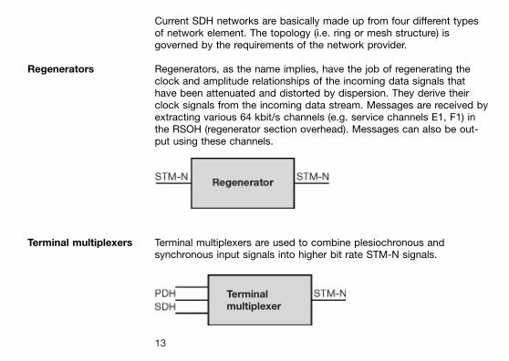
Current SDH networks are basically made up from four different typesof network element. The topology (i.e. ring or mesh structure) isgoverned by the requirements of the network provider.
Regenerators Regenerators, as the name implies, have the job of regenerating theclock and amplitude relationships of the incoming data signals thathave been attenuated and distorted by dispersion. They derive theirclock signals from the incoming data stream. Messages are received byextracting various 64 kbit/s channels (e.g. service channels E1, F1) inthe RSOH (regenerator section overhead). Messages can also be out-put using these channels.
Terminal multiplexers Terminal multiplexers are used to combine plesiochronous andsynchronous input signals into higher bit rate STM-N signals.
Terminalmultiplexer
13
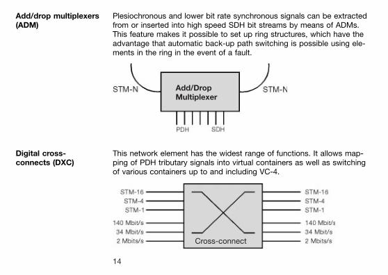
Add/drop multiplexers(ADM)
Plesiochronous and lower bit rate synchronous signals can be extractedfrom or inserted into high speed SDH bit streams by means of ADMs.This feature makes it possible to set up ring structures, which have theadvantage that automatic back-up path switching is possible using ele-ments in the ring in the event of a fault.
Digital cross-connects (DXC)
This network element has the widest range of functions. It allows map-ping of PDH tributary signals into virtual containers as well as switchingof various containers up to and including VC-4.
Add/DropMultiplexer
Cross-connect
14
Network elementmanagement
The telecommunications management network (TMN) is considered asa further element in the synchronous network. All the SDH network ele-ments mentioned so far are software-controlled. This means that theycan be monitored and remotely controlled, one of the most importantfeatures of SDH. Network management is described in more detail inthe section ªTMN in the SDH networkº.
Optical fibers are the physical medium most used for SDH networks.The advantage of optical fibers is that they are not susceptible to inter-ference and they can transmit at very high speeds (also see underDWDM). The disadvantage is the relatively high cost of procurementand installation. Single-mode fibers for the first and second optical win-dows (1310 nm and 1550 nm) are the medium of choice.
A further possible method of transmitting SDH signals is via radio linkor satellite paths. These are particularly suitable for setting up trans-mission paths quickly, or as a part of a mobile radio network or in diffi-cult terrain. Disadvantages here are the limited bandwidth (currently upto STM-4) and the relatively complex business of linking such pathsinto the network management system.
15
The STM-1frame format
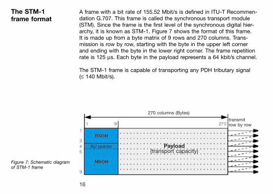
A frame with a bit rate of 155.52 Mbit/s is defined in ITU-T Recommen-dation G.707. This frame is called the synchronous transport module(STM). Since the frame is the first level of the synchronous digital hier-archy, it is known as STM-1. Figure 7 shows the format of this frame.It is made up from a byte matrix of 9 rows and 270 columns. Trans-mission is row by row, starting with the byte in the upper left cornerand ending with the byte in the lower right corner. The frame repetitionrate is 125 ms. Each byte in the payload represents a 64 kbit/s channel.
The STM-1 frame is capable of transporting any PDH tributary signal(£ 140 Mbit/s).
Figure 7: Schematic diagramof STM-1 frame
270 columns (Bytes)
transmitrow by row
AU pointer Payload(transport capacity)
16
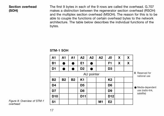
Section overhead(SOH)
The first 9 bytes in each of the 9 rows are called the overhead. G.707makes a distinction between the regenerator section overhead (RSOH)and the multiplex section overhead (MSOH). The reason for this is to beable to couple the functions of certain overhead bytes to the networkarchitecture. The table below describes the individual functions of thebytes.
Figure 8: Overview of STM-1overhead
STM-1 SOH
A1 A1 A1 A2 A2 A2 J0 X X
B1 * * E1 * F1 X X
D1 * * D2 * D3
AU pointer
B2 B2 B2 K1 K2
D4 D5 D6
D7 D8 D9
D10 D11 D12
S1 M1 E2
X Reserved fornational use
*Media-dependentuse (radio-link,satellite)
17
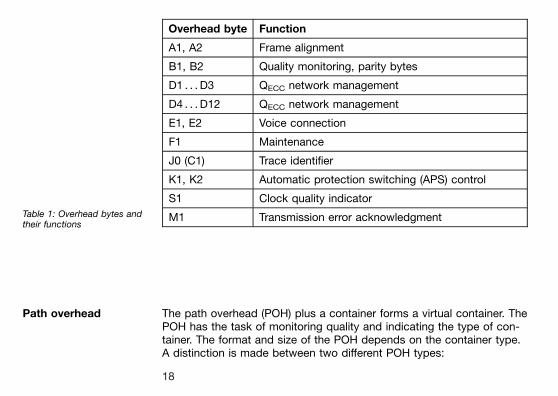
Overhead byte Function
A1, A2 Frame alignment
B1, B2 Quality monitoring, parity bytes
D1 . . . D3 QECC network management
D4 . . . D12 QECC network management
E1, E2 Voice connection
F1 Maintenance
J0 (C1) Trace identifier
K1, K2 Automatic protection switching (APS) control
S1 Clock quality indicator
M1 Transmission error acknowledgmentTable 1: Overhead bytes andtheir functions
Path overhead The path overhead (POH) plus a container forms a virtual container. ThePOH has the task of monitoring quality and indicating the type of con-tainer. The format and size of the POH depends on the container type.A distinction is made between two different POH types:
18
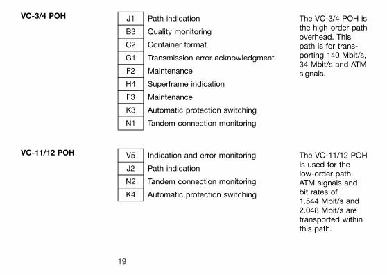
VC-3/4 POH J1 Path indication The VC-3/4 POH isthe high-order pathoverhead. Thispath is for trans-porting 140 Mbit/s,34 Mbit/s and ATMsignals.
B3 Quality monitoring
C2 Container format
G1 Transmission error acknowledgment
F2 Maintenance
H4 Superframe indication
F3 Maintenance
K3 Automatic protection switching
N1 Tandem connection monitoring
VC-11/12 POH V5 Indication and error monitoring The VC-11/12 POHis used for thelow-order path.ATM signals andbit rates of1.544 Mbit/s and2.048 Mbit/s aretransported withinthis path.
J2 Path indication
N2 Tandem connection monitoring
K4 Automatic protection switching
19
How are PDH andATM signals trans-ported by SDH?
The heterogeneous nature of modern network structures has made itnecessary that all PDH and ATM signals are transported over the SDHnetwork. The process of matching the signals to the network is calledmapping. The container is the basic package unit for tributary channels.A special container (C-n) is provided for each PDH tributary signal.These containers are always much larger than the payload to be trans-ported. The remaining capacity is used partly for justification (stuffing)in order to equalize out timing inaccuracies in the PDH signals. Wheresynchronous tributaries are mapped, fixed fill bytes are inserted insteadof justification bytes. A virtual container (VC-n) is made up from thecontainer thus formed together with the path overhead (POH). This istransmitted unchanged over a path through the network. The next steptowards formation of a complete STM-N signal is the addition of apointer indicating the start of the POH. The unit formed by the pointerand the virtual container is called an administrative unit (AU-n) or atributary unit (TU-n).Several TUs taken together form a tributary unit group (TUG-n); theseare in turn collected together into a VC. One or more AUs form an ad-ministrative unit group (AUG). Finally, the AUG plus the section over-head (SOH) forms the STM-N.
20
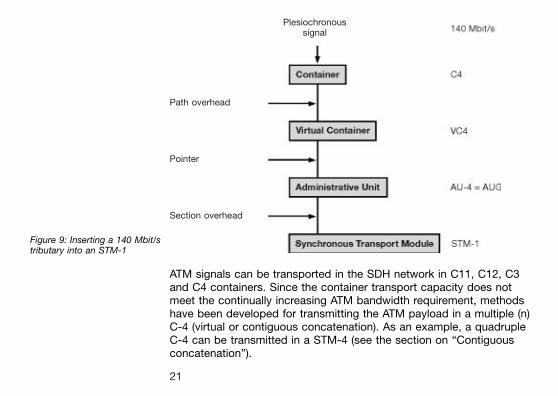
Figure 9: Inserting a 140 Mbit/stributary into an STM-1
ATM signals can be transported in the SDH network in C11, C12, C3and C4 containers. Since the container transport capacity does notmeet the continually increasing ATM bandwidth requirement, methodshave been developed for transmitting the ATM payload in a multiple (n)C-4 (virtual or contiguous concatenation). As an example, a quadrupleC-4 can be transmitted in a STM-4 (see the section on ªContiguousconcatenationº).
Plesiochronoussignal
Path overhead
Pointer
Section overhead
21
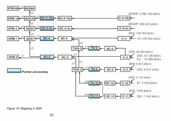
Figure 10: Mapping in SDH
Pointer processing
22
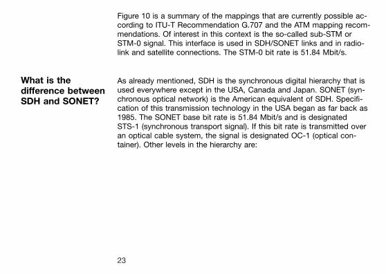
Figure 10 is a summary of the mappings that are currently possible ac-cording to ITU-T Recommendation G.707 and the ATM mapping recom-mendations. Of interest in this context is the so-called sub-STM orSTM-0 signal. This interface is used in SDH/SONET links and in radio-link and satellite connections. The STM-0 bit rate is 51.84 Mbit/s.
What is thedifference betweenSDH and SONET?
As already mentioned, SDH is the synchronous digital hierarchy that isused everywhere except in the USA, Canada and Japan. SONET (syn-chronous optical network) is the American equivalent of SDH. Specifi-cation of this transmission technology in the USA began as far back as1985. The SONET base bit rate is 51.84 Mbit/s and is designatedSTS-1 (synchronous transport signal). If this bit rate is transmitted overan optical cable system, the signal is designated OC-1 (optical con-tainer). Other levels in the hierarchy are:
23
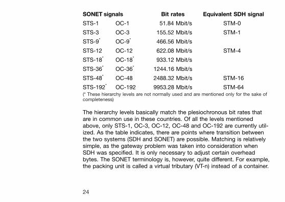
SONET signals Bit rates Equivalent SDH signal
STS-1 OC-1 51.84 Mbit/s STM-0
STS-3 OC-3 155.52 Mbit/s STM-1
STS-9* OC-9* 466.56 Mbit/s
STS-12 OC-12 622.08 Mbit/s STM-4
STS-18* OC-18* 933.12 Mbit/s
STS-36* OC-36* 1244.16 Mbit/s
STS-48* OC-48 2488.32 Mbit/s STM-16
STS-192* OC-192 9953.28 Mbit/s STM-64(* These hierarchy levels are not normally used and are mentioned only for the sake ofcompleteness)
The hierarchy levels basically match the plesiochronous bit rates thatare in common use in these countries. Of all the levels mentionedabove, only STS-1, OC-3, OC-12, OC-48 and OC-192 are currently util-ized. As the table indicates, there are points where transition betweenthe two systems (SDH and SONET) are possible. Matching is relativelysimple, as the gateway problem was taken into consideration whenSDH was specified. It is only necessary to adjust certain overheadbytes. The SONET terminology is, however, quite different. For example,the packing unit is called a virtual tributary (VT-n) instead of a container.
24
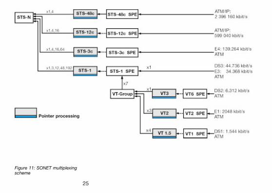
Figure 11: SONET multiplexingscheme
Pointer processing
25
Pointer procedures The use of pointer procedures also gives synchronous communicationsa distinct advantage over the plesiochronous hierarchy. Pointers areused to localize individual virtual containers in the payload of thesynchronous transport module. The pointer may directly indicate asingle VC-n virtual container from the upper level of the STM-1 frame.Chained pointer structures can also be used. The AU-4 pointer initiallyindicates the VC-4 overhead. Three further pointers are located at fixedpositions in the VC-4; these indicate the start of the three VC-3 virtualcontainers relative to the VC-4. Figure 12 describes the pointer pro-cedure using C3 mapping as an example.
26
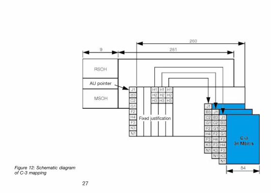
Figure 12: Schematic diagramof C-3 mapping
AU pointer
Fixed justification
27
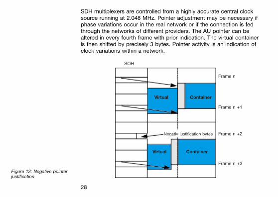
SDH multiplexers are controlled from a highly accurate central clocksource running at 2.048 MHz. Pointer adjustment may be necessary ifphase variations occur in the real network or if the connection is fedthrough the networks of different providers. The AU pointer can bealtered in every fourth frame with prior indication. The virtual containeris then shifted by precisely 3 bytes. Pointer activity is an indication ofclock variations within a network.
Figure 13: Negative pointerjustification
SOH
Virtual Container
Negativ justification bytes
Virtual Container
Frame n
Frame n +1
Frame n +2
Frame n +3
28
If the pointer is shifted to a later point in time (to the right in the dia-gram), the 3 bytes immediately preceding it will be ignored. If the trans-mitting source is in advance of the actual clock, space for extracapacity must be provided. This takes place at the pointer position intowhich three bytes are slipped each time. If a further clock adjustment isnot made, this configuration will be propagated throughout the network.This allows, on the one hand, the free insertion in time of user signalsinto the next higher frame structure in the form of virtual containerswithout the need for larger buffers. On the other hand, changes in thephase location of the virtual container relative to the superior frame canbe corrected by appropriate pointer actions. Such changes and shiftsin phase can be caused by changes in propagation delay in the trans-mission medium or by non-synchronous branches in the real network.When a multiplex bundle is resolved, pointer procedures make it poss-ible to immediately locate every user channel from each STM-N frame,which considerably simplifies drop and insert operations within a net-work node. In contrast, complete demultiplexing of every level of a ple-siochronous hierarchy signal is required in order to access a particulartributary channel.
29
AU-4 contiguousconcatenation
This mechanism is provided to allow bit rates in excess of the capacityof the C-4 container to be transmitted. For example, the AU-4-4c isintended for transporting B-ISDN bit rates. The advantage of thismethod is that the payload must not be split up, since a virtually con-tiguous container is formed within an STM-4. The payloads of severalconsecutive AU-4s are linked by setting all the pointers to a fixed value,the concatenation indicator (CI), with the exception of the pointer forthe first AU-4. If pointer activity becomes necessary, this takes placefor all concatenated AU-4s equally. Figure 14 shows how the payloadof ATM cells can be transmitted as a whole.
30
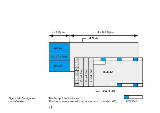
Figure 14: Contiguousconcatenation
Fix
ed
Stu
ff
Fix
ed
Stu
ff
Fix
ed
Stu
ff
469 Bytes 46261 Bytes
STM-4
RSOH
AU-4 Pointers
MSOH
C-4-4c
VC-4-4c
The first pointer indicates J1All other pointers are set to concatenation indication (Cl) ATM Cell
31
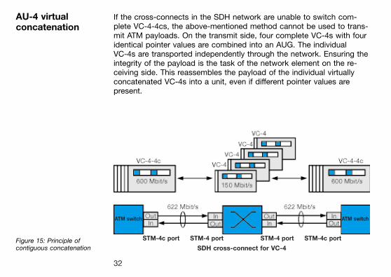
AU-4 virtualconcatenation
If the cross-connects in the SDH network are unable to switch com-plete VC-4-4cs, the above-mentioned method cannot be used to trans-mit ATM payloads. On the transmit side, four complete VC-4s with fouridentical pointer values are combined into an AUG. The individualVC-4s are transported independently through the network. Ensuring theintegrity of the payload is the task of the network element on the re-ceiving side. This reassembles the payload of the individual virtuallyconcatenated VC-4s into a unit, even if different pointer values arepresent.
Figure 15: Principle ofcontiguous concatenation
ATM switch ATM switch
STM-4c port STM-4 port STM-4 port STM-4c port
SDH cross-connect for VC-4
32
Transmissionat higher hierarchylevels
To achieve higher bit rates, AU-3/4s are multiplexed into STM-N frames.The following hierarchy levels are defined in SDH:
STM-1 155.52 Mbit/sSTM-4 622.08 Mbit/sSTM-16 2488.32 Mbit/sSTM-64 9953.28 Mbit/s
The STM-N frame structures are basically N times the STM-1 structure.For example, the STM-4 overhead is four times the size of the STM-1overhead. The SOH content is specified for each stage individually. Forthis, the A1, A2 and B2 bytes are formed N times.
33
Error and alarmmonitoring
Large numbers of alarm and error messages are an integral part ofSDH networks. In SDH, these are referred to as defects and anomalies,respectively. They are coupled to network sections and the correspond-ing overhead information. The advantage of this detailed information isillustrated as follows:Complete failure of a circuit results, for example, in a LOS alarm (lossof signal) in the receiving network element. This alarm triggers a com-plete chain of subsequent messages in the form of AIS (alarm indica-tion signals; see figure 16). The transmitting side is informed of thefailure by the return of an RDI alarm (remote defect indication). Thealarm messages are transmitted in fixed bytes in the SOH or POH. Forexample, byte G1 is used for the HP-RDI alarm.
34
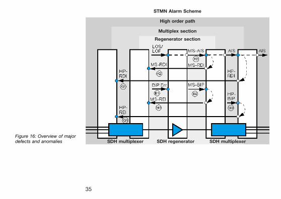
Figure 16: Overview of majordefects and anomalies
STMN Alarm Scheme
High order path
Multiplex section
Regenerator section
SDH multiplexer SDH regenerator SDH multiplexer
± ± ±
35
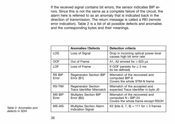
If the received signal contains bit errors, the sensor indicates BIP er-rors. Since this is not the same as a complete failure of the circuit, thealarm here is referred to as an anomaly that is indicated back in thedirection of transmission. The return message is called a REI (remoteerror indication). Table 2 is a list of all possible defects and anomaliesand the corresponding bytes and their meanings.
Anomalies / Defects Detection criteria
LOS Loss of Signal Drop in incoming optical power levelcauses high bit error rate
OOF Out of Frame A1, A2 errored for ³ 625 ms
LOF Loss of Frame If OOF persists for ³ 3 ms(to be defined)
RS BIPError
Regenerator Section BIPError (B1)
Mismatch of the recovered andcomputed BIP-8Covers the whole STM-N frame
RS-TIM Regenerator SectionTrace Identifier Mismatch
Mismatch of the accepted andexpected Trace Identifier in byte J0
MS BIPError
Multiplex Section BIPError (B2)
Mismatch of the recovered andcomputed N6BIP-24Covers the whole frame except RSOH
MS-AIS Multiplex Section AlarmIndication Signal
K2 (bits 6, 7, 8) = 111 for ³ 3 framesTable 2: Anomalies anddefects in SDH
36
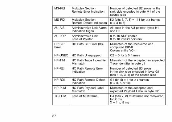
MS-REI Multiplex SectionRemote Error Indication
Number of detected B2 errors in thesink side encoded in byte M1 of thesource side
MS-RDI Multiplex SectionRemote Defect Indication
K2 (bits 6, 7, 8) = 111 for ³ z frames(z = 3 to 5)
AU-AIS Administrative Unit AlarmIndication Signal
All ones in the AU pointer bytes H1and H2
AU-LOP Administrative UnitLoss of Pointer
8 to 10 NDF enable8 to 10 invalid pointers
HP BIPError
HO Path BIP Error (B3) Mismatch of the recovered andcomputed BIP-8Covers entire VC-n
HP-UNEQ HO Path Unequipped C2 = 0 for ³ 5 frames
HP-TIM HO Path Trace IndentifierMismatch
Mismatch of the accepted an expectedTrace Identifier in byte J1
HP-REI HO Path Remote ErrorIndication
Number of detected B3 errorsin the sink side encoded in byte G1(bits 1, 2, 3, 4) of the source side
HP-RDI HO Path Remote DefectIndication
G1 (bit 5) = 1 for ³ z frames(z = 3, 5 or 10)
HP-PLM HO Path Payload LabelMismatch
Mismatch of the accepted andexpected Payload Label in byte C2
TU-LOM Loss of Multiframe H4 (bits 7, 8) multiframe not recoveredfor X msX = 1 to 5 ms
37
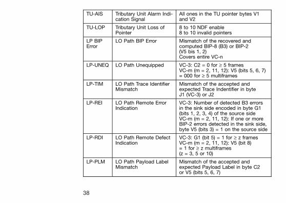
TU-AIS Tributary Unit Alarm Indi-cation Signal
All ones in the TU pointer bytes V1and V2
TU-LOP Tributary Unit Loss ofPointer
8 to 10 NDF enable8 to 10 invalid pointers
LP BIPError
LO Path BIP Error Mismatch of the recovered andcomputed BIP-8 (B3) or BIP-2(V5 bis 1, 2)Covers entire VC-n
LP-UNEQ LO Path Unequipped VC-3: C2 = 0 for ³ 5 framesVC-m (m = 2, 11, 12): V5 (bits 5, 6, 7)= 000 for ³ 5 multiframes
LP-TIM LO Path Trace IdentifierMismatch
Mismatch of the accepted andexpected Trace Indentifier in byteJ1 (VC-3) or J2
LP-REI LO Path Remote ErrorIndication
VC-3: Number of detected B3 errorsin the sink side encoded in byte G1(bits 1, 2, 3, 4) of the source sideVC-m (m = 2, 11, 12): If one or moreBIP-2 errors detected in the sink side,byte V5 (bits 3) = 1 on the source side
LP-RDI LO Path Remote DefectIndication
VC-3: G1 (bit 5) = 1 for ³ z framesVC-m (m = 2, 11, 12): V5 (bit 8)= 1 for ³ z multiframes(z = 3, 5 or 10)
LP-PLM LO Path Payload LabelMismatch
Mismatch of the accepted andexpected Payload Label in byte C2or V5 (bits 5, 6, 7)
38
Back-up networkswitching
Modern society is virtually completely dependent on communicationstechnology. Trying to imagine a modern office without any connectionto telephone or data networks is like trying to work out how a laundrycan operate without water. Network failures, whether due to humanerror or faulty technology, can be very expensive for users and networkproviders alike. As a result, the subject of so-called fall-back mechan-isms is currently one of the most talked about in the SDH world.A wide range of standardized mechanisms is incorporated intosynchronous networks in order to compensate for failures in networkelements.
Automaticprotectionswitching (APS)
Two basic types of protection architecture are distinguished in APS.One is the linear protection mechanism used for point-to-point connec-tions. The other basic form is the so-called ring protection mechanismwhich can take on many different forms. Both mechanisms use sparecircuits or components to provide the back-up path. Switching is con-trolled by the overhead bytes K1 and K2.
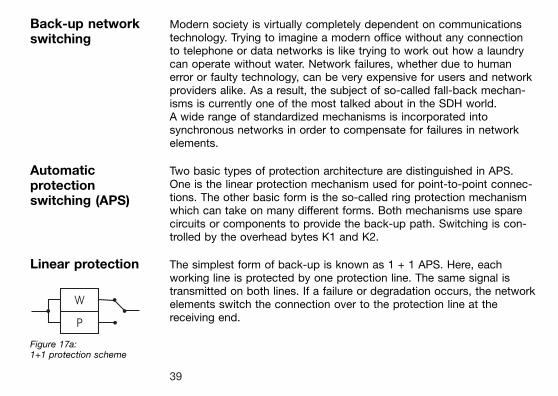
Linear protection The simplest form of back-up is known as 1 + 1 APS. Here, eachworking line is protected by one protection line. The same signal istransmitted on both lines. If a failure or degradation occurs, the networkelements switch the connection over to the protection line at thereceiving end.
Figure 17a:1+1 protection scheme
39
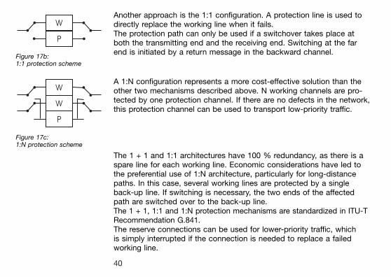
Figure 17b:1:1 protection scheme
Another approach is the 1:1 configuration. A protection line is used todirectly replace the working line when it fails.The protection path can only be used if a switchover takes place atboth the transmitting end and the receiving end. Switching at the farend is initiated by a return message in the backward channel.
Figure 17c:1:N protection scheme
A 1:N configuration represents a more cost-effective solution than theother two mechanisms described above. N working channels are pro-tected by one protection channel. If there are no defects in the network,this protection channel can be used to transport low-priority traffic.
The 1 + 1 and 1:1 architectures have 100 % redundancy, as there is aspare line for each working line. Economic considerations have led tothe preferential use of 1:N architecture, particularly for long-distancepaths. In this case, several working lines are protected by a singleback-up line. If switching is necessary, the two ends of the affectedpath are switched over to the back-up line.The 1 + 1, 1:1 and 1:N protection mechanisms are standardized in ITU-TRecommendation G.841.The reserve connections can be used for lower-priority traffic, whichis simply interrupted if the connection is needed to replace a failedworking line.
40
Ring protection The greater the communications bandwidth carried by optical fibers,the greater the cost advantages of ring structures as compared withlinear structures. A ring is the simplest and most cost-effective way oflinking a number of network elements.Various protection mechanisms are available for this type of networkarchitecture, only some of which have been standardized in ITU-TRecommendation G.841. A basic distinction must be made betweenring structures with unidirectional and bi-directional connections.
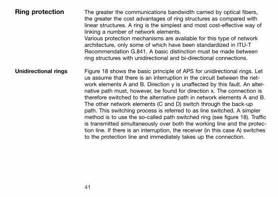
Unidirectional rings Figure 18 shows the basic principle of APS for unidirectional rings. Letus assume that there is an interruption in the circuit between the net-work elements A and B. Direction y is unaffected by this fault. An alter-native path must, however, be found for direction x. The connection istherefore switched to the alternative path in network elements A and B.The other network elements (C and D) switch through the back-uppath. This switching process is referred to as line switched. A simplermethod is to use the so-called path switched ring (see figure 18). Trafficis transmitted simultaneously over both the working line and the protec-tion line. If there is an interruption, the receiver (in this case A) switchesto the protection line and immediately takes up the connection.
41
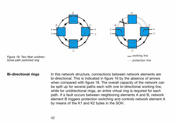
Figure 18: Two fiber unidirec-tional path switched ring
Bi-directional rings In this network structure, connections between network elements arebi-directional. This is indicated in figure 19 by the absence of arrowswhen compared with figure 18. The overall capacity of the network canbe split up for several paths each with one bi-directional working line,while for unidirectional rings, an entire virtual ring is required for eachpath. If a fault occurs between neighboring elements A and B, networkelement B triggers protection switching and controls network element Aby means of the K1 and K2 bytes in the SOH.
working line
protection line
42
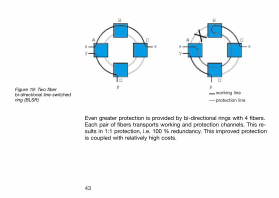
Figure 19: Two fiberbi-directional line-switchedring (BLSR)
Even greater protection is provided by bi-directional rings with 4 fibers.Each pair of fibers transports working and protection channels. This re-sults in 1:1 protection, i.e. 100 % redundancy. This improved protectionis coupled with relatively high costs.
y y
working line
protection line
43
Synchronization Synchronous is the first word in the term SDH for a very good reason.If synchronization is not guaranteed, considerable degradation in net-work function, and even total failure of the network can be the result.To avoid this worst case scenario, all network elements are synchron-ized to a central clock. This central clock is generated by a high-pre-cision primary reference clock (PRC) unit conforming to ITU-TRecommendation G.811. This specifies an accuracy of 1610-11. Thisclock signal must be distributed throughout the entire network. A hier-archical structure is used for this; the signal is passed on by the sub-ordinate synchronization supply units (SSU) and synchronousequipment clocks (SEC). The synchronization signal paths can be thesame as those used for SDH communications.
44
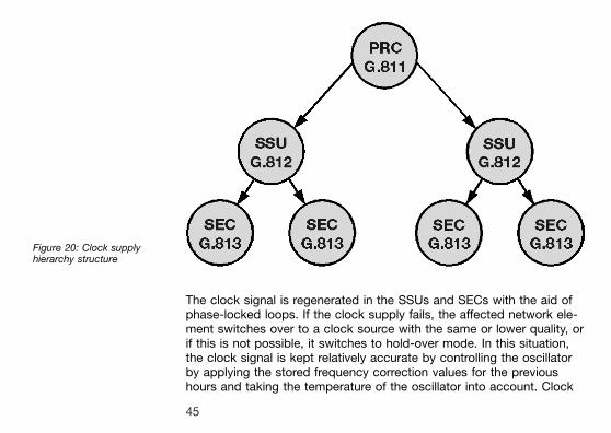
Figure 20: Clock supplyhierarchy structure
The clock signal is regenerated in the SSUs and SECs with the aid ofphase-locked loops. If the clock supply fails, the affected network ele-ment switches over to a clock source with the same or lower quality, orif this is not possible, it switches to hold-over mode. In this situation,the clock signal is kept relatively accurate by controlling the oscillatorby applying the stored frequency correction values for the previoushours and taking the temperature of the oscillator into account. Clock
45
ªislandsº must be avoided at all costs, as these would drift out of syn-chronization with the passage of time and the total failure disasterwould be the result. Such islands are prevented by signaling the net-work elements with the aid of synchronization status messages (SSM,part of the S1 byte). The SSM informs the neighboring network elementabout the status of the clock supply and is part of the overhead.
Special problems arise at gateways between networks with indepen-dent clock supplies. SDH network elements can compensate for clockoffsets within certain limits by means of pointer operations. Pointer ac-tivity is thus a reliable indicator of problems with the clock supply.
46
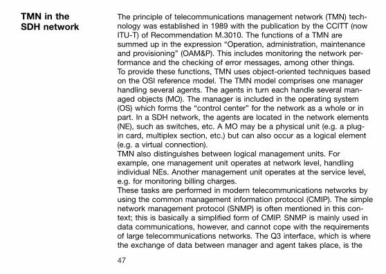
TMN in theSDH network
The principle of telecommunications management network (TMN) tech-nology was established in 1989 with the publication by the CCITT (nowITU-T) of Recommendation M.3010. The functions of a TMN aresummed up in the expression ªOperation, administration, maintenanceand provisioningº (OAM&P). This includes monitoring the network per-formance and the checking of error messages, among other things.To provide these functions, TMN uses object-oriented techniques basedon the OSI reference model. The TMN model comprises one managerhandling several agents. The agents in turn each handle several man-aged objects (MO). The manager is included in the operating system(OS) which forms the ªcontrol centerº for the network as a whole or inpart. In a SDH network, the agents are located in the network elements(NE), such as switches, etc. A MO may be a physical unit (e.g. a plug-in card, multiplex section, etc.) but can also occur as a logical element(e.g. a virtual connection).TMN also distinguishes between logical management units. Forexample, one management unit operates at network level, handlingindividual NEs. Another management unit operates at the service level,e.g. for monitoring billing charges.These tasks are performed in modern telecommunications networks byusing the common management information protocol (CMIP). The simplenetwork management protocol (SNMP) is often mentioned in this con-text; this is basically a simplified form of CMIP. SNMP is mainly used indata communications, however, and cannot cope with the requirementsof large telecommunications networks. The Q3 interface, which is wherethe exchange of data between manager and agent takes place, is the
47
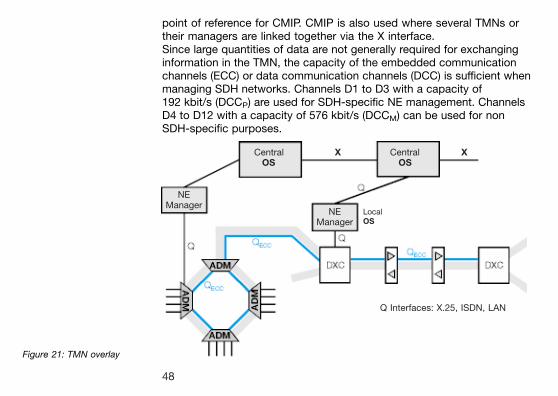
point of reference for CMIP. CMIP is also used where several TMNs ortheir managers are linked together via the X interface.Since large quantities of data are not generally required for exchanginginformation in the TMN, the capacity of the embedded communicationchannels (ECC) or data communication channels (DCC) is sufficient whenmanaging SDH networks. Channels D1 to D3 with a capacity of192 kbit/s (DCCP) are used for SDH-specific NE management. ChannelsD4 to D12 with a capacity of 576 kbit/s (DCCM) can be used for nonSDH-specific purposes.
Figure 21: TMN overlay
Central X Central XOS OS
NEManager
NEManager
LocalOS
Q Interfaces: X.25, ISDN, LAN
48
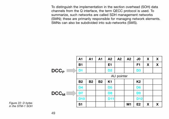
To distinguish the implementation in the section overhead (SOH) datachannels from the Q interface, the term QECC protocol is used. Tosummarize, such networks are called SDH management networks(SMN); these are primarily responsible for managing network elements.SMNs can also be subdivided into sub-networks (SMS).
Figure 22: D bytesin the STM-1 SOH
A1 A1 A1 A2 A2 A2 J0 X X
B1 E1 F1 X X
D1 D2 D3
AU pointer
B2 B2 B2 K1 K2
D4 D5 D6
D7 D8 D9
D10 D11 D12
S1 M1 E2 X X
DCCPá
DCCMá
49
SDH measurementtasks
Why are separate measurement procedures required for today's TMN-controlled SDH networks? Is it in fact possible to do without test equip-ment in general? These or similar questions may arise in your mind,now that you are familiar with the way that SDH networks are con-structed and with the basic principles governing their functions.Although trouble-free operation of all network elements should havebeen guaranteed by standardization on the part of various bodies (ITU,ETSI, ANSI, Bellcore), problems still arise, particularly when networkelements from different sources are linked together. Transmission prob-lems also occur at gateways between networks run by different pro-viders. The measurement facilities built in to the system provide only arough idea of the location of a fault. Separate measuring equipment, incontrast, is of much greater usefulness, particularly when it comes tomonitoring individual channels. Much more data relevant to clearing thefault can be obtained. The only areas that are covered by both networkmanagement and measurement procedures are long term analysis andsystem monitoring.
Separate measuring equipment of course finds further application in thefields of research and development, production and installation. Theseareas in particular require test equipment with widely differing specifi-cations.
Take production and installation as an example: Systems manufacturersconfigure their network elements or entire networks according to cus-tomer requirements and use measuring techniques to check that every-
50
thing operates as it should. Next, the equipment is installed on the cus-tomer's site and put into operation. Test equipment is essential at thisstage to eliminate any faults that may have occurred during productionand installation and to verify correct function. Such test equipmentneeds to be portable and robust, and capable of performing test se-quences in order to reliably and quickly reproduce repeat measure-ments and long-term analyses.
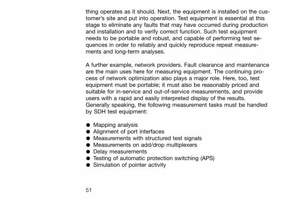
A further example, network providers. Fault clearance and maintenanceare the main uses here for measuring equipment. The continuing pro-cess of network optimization also plays a major role. Here, too, testequipment must be portable; it must also be reasonably priced andsuitable for in-service and out-of-service measurements, and provideusers with a rapid and easily interpreted display of the results.Generally speaking, the following measurement tasks must be handledby SDH test equipment:
* Mapping analysis* Alignment of port interfaces* Measurements with structured test signals* Measurements on add/drop multiplexers* Delay measurements* Testing of automatic protection switching (APS)* Simulation of pointer activity
51
* In-service SDH measurementsAlarm analysisPath trace monitoringPointer analysisChecking the sensors built-in to the systemDrop and insert measurementsChecking network synchronizationMeasurements on the TMN interface
* Quality evaluation as per G.821, G.826 and M.2100* Jitter and wander analysis
Some of these measurements are discussed in more detail below.
Sensor tests These measurements are performed in order to check the reaction ofsystem components to defects and anomalies. Anomalies are faultssuch as parity errors. Defects result in the interruption of a connection.For example, a network element must react to a LOS (loss of signal)alarm by sending AIS (alarm indication signal) to the subsequent net-work elements and transmitting a RDI (remote defect indication) signalin the return path (compare figure 10).
52
APS timemeasurements
A special mechanism operates in SDH networks in the event of a fault.The faulty link is automatically re-routed over a back up circuit (seeªAutomatic protection switching (APS)º, above). This function is con-trolled using overhead bytes K1 and K2. Switching over to the protec-tion line must take place in less than 50 ms. To ensure that this is so,external test equipment is needed.This is used to measure the response time (i.e. loss of a specific testpattern or triggering a pre-set alarm) when a connection is intentionallyinterrupted (see figure 23). The measurement is very important, as a de-layed response can result in considerable degradation in performanceand even to a total failure of the network and major loss of income forthe network provider.
53
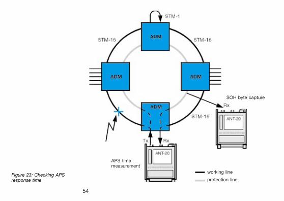
Figure 23: Checking APSresponse time
working line
protection line
SOH byte capture
APS timemeasurement
54
G.821, G.826,M.2100 and M. 2101performanceanalysis
The quality of digital links is determined with the aid of bit error ratiotests (BERT). The results of such measurements must, however, beclassified in some way, not least because the quality of a transmissionpath is often the subject of a contract between the network providerand the telecommunications user. For this reason, an objective meansof classifying a line as either ªgoodº or ªbadº is required. The ITU-TRecommendations G.821, G.826 and M.2100 are internationally recog-nized standards that specify these parameters.
G.821 This Recommendation was originally specified for international circuit-switched n664 kbit/s connections and expanded to include higher bitrates as time went on. A hypothetical reference connection is the basisused for determining quality parameters; this comprises an internationallong-distance segment, a national segment and a subscriber accesssegment.
G.821 definitions:* Errored second (ES): A one-second time interval in which one or
more bit errors occurs.* Severely errored second (SES): A one-second time interval in which
the bit error ratio exceeds 10-3.* Unavailable second (US): A circuit is considered to be unavailable
from the first of at least ten consecutive SES. The circuit is availablefrom the first of at least ten consecutive seconds which are not SES.
55
The original version of G.821 also included:* Degraded minute (DM): A one-minute time interval in which the bit
error ratio exceeds 10-6.
Derived parameter:* Error-free second (EFS): A one-second time interval in which no bit
errors occur.
The disadvantage of this method is that it relies on the evaluation of biterrors and so the test channel must be taken out of service to performthe measurement.
G.826 This Recommendation, issued in 1993, takes higher bit rates into ac-count and allows in-service measurement as it relies on the evaluationof block errors.
G.826 definitions:* Errored second (ES): A one-second time interval containing one or
more errored blocks.* Errored block (EB): A block containing one or more errored bits.* Severely errored second (SES): A one-second time interval in which
more than 30 % of the blocks are errored or which contains at leastone severely disturbed period (SDP).
* Background block error (BBE): An errored block that is not a SES.* Unavailable second (US): see under G.821, above.
56
The results are referred to the measurement time. This gives the follow-ing error parameters: Errored seconds ratio (ESR), severely errored sec-onds ratio (SESR) and background block error ratio (BBER). Thespecified quality requirements refer to a particular path.The recommended measurement time for G.821 and G.826 is 30 days.
M.2100 Recommendation M.2100 specifically applies to commissioning andmaintenance. Commissioning consists of a 15-minute line up phase fol-lowed by a 24-hour in-service measurement. Once the line up phase iscompleted successfully, errors may occur within certain limits. If this isthe case, the line remains in service, but must continue to be monitoredfor a further 7 days. The measurement procedures are defined inM.2110 and M.2120. The limit values are derived form the performanceparameters specified in G.821 and G.826.
M.2101 This Recommendation is very close to M.2100 in terms of purpose andformat, but it deals exclusively with SDH systems. M.2101 includesuseful tables covering bringing-into-service performance objectives andthe computational techniques for determining parameters are essentiallythe same. M.2101 for SDH systems can thus be considered as a sisterRecommendation to M.2100 for PDH systems.
57
Tandem connectionmonitoring (TCM)
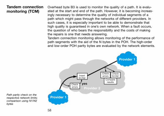
Overhead byte B3 is used to monitor the quality of a path. It is evalu-ated at the start and end of the path. However, it is becoming increas-ingly necessary to determine the quality of individual segments of apath which might pass through the networks of different providers. Insuch cases, it is especially important to be able to demonstrate thathigh quality is guaranteed in one's own network. When a fault occurs,the question of who bears the responsibility and the costs of makingthe repairs is one that needs answering.Tandem connection monitoring allows monitoring of the performance ofpath segments with the aid of the N bytes in the POH. The high-orderand low-order POH parity bytes are evaluated by the network elements.
Path parity check on therespective network limits;comparison using N1/N2bytes
Provider 1
Provider 1
Provider 2
InsertN1/N2
Checkerrors
CheckN1/N2
Compareresults
Checkerrors
yes
58
The number of errors detected is indicated to the end of the TCM usingthe N1 or N2 byte. This error count is then recompared with the numberof parity errors detected at the end of the TCM. The difference is thenumber of errors occurring within the TCM.
Jittermeasurements
The term jitter refers to phase variations in a digital signal. Put anotherway, the edges of the digital signal may differ from the expected idealpositions in time. Jitter is described in terms of its amplitude (expressedin unit intervals, UI) and its frequency. If the jitter frequency is below10 Hz, the term used is wander. Signals that are affected by jitter can-not be sampled accurately; in an extreme situation, this might result inmisinterpretation of the input signal. This results in single errors or errorbursts and a corresponding degradation in transmission quality. Jitterand wander can also be the cause of buffer underflow or overflow,which leads to bit slips. The theoretical limit of correct sampling at highjitter frequencies is half the bit width. Distortion and additive noisemeans that the actual limit must be set much lower than this.What causes jitter? The clock sources for network elements such asregenerators and add/drop multiplexers are one possible cause. Varioustypes of jitter are differentiated as shown in the following table.
59
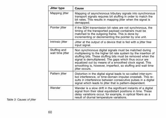
Jitter type Cause
Mapping jitter Mapping of asynchronous tributary signals into synchronoustransport signals requires bit stuffing in order to match thebit rates. This results in mapping jitter when the signal isdemapped.
Pointer jitter If the SDH transmission bit rates are not synchronous, thetiming of the transported payload containers must bematched to the outgoing frame. This is done byincrementing or decrementing the pointer by one unit.
Intrinsic jitter Jitter at the output of a device that is fed with a jitter freeinput signal.
Stuffing andwait time jitter
Non synchronous digital signals must be matched duringmultiplexing to the higher bit rate system by the insertion ofstuffing bits. These stuffing bits must be removed when thesignal is demultiplexed. The gaps which thus occur areequalized out by means of a smoothed clock signal. Thissmoothing is, however, imperfect, so stuffing and wait timejitter occurs.
Pattern jitter Distortion in the digital signal leads to so-called inter-sym-bol interference, or time-domain impulse crosstalk. This re-sults in interference between consecutive pulses in a digitalsignal which leads to jitter that is pattern-dependent.
Wander Wander is a slow drift in the significant instants of a digitalsignal from their ideal equidistant positions in time. Thesedelay variations occur, for example, in optical fibers as aresult of diurnal temperature variations.
Table 3: Causes of jitter
60
Other causes of jitter are interference signals and phase noise. Jittercaused by interference signals is also called non-systematic jitter.Phase noise occurs despite the use of a central clock as a result ofthermal noise and drift in the oscillator used. Various measurementmethods have been developed for the different causes of jitter.
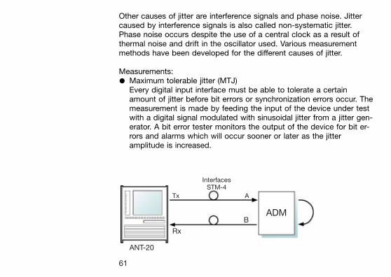
Measurements:* Maximum tolerable jitter (MTJ)
Every digital input interface must be able to tolerate a certainamount of jitter before bit errors or synchronization errors occur. Themeasurement is made by feeding the input of the device under testwith a digital signal modulated with sinusoidal jitter from a jitter gen-erator. A bit error tester monitors the output of the device for bit er-rors and alarms which will occur sooner or later as the jitteramplitude is increased.
InterfacesSTM-4
Tx A
ADMB
Rx
ANT-20
61
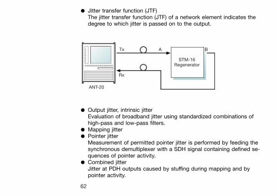
* Jitter transfer function (JTF)The jitter transfer function (JTF) of a network element indicates thedegree to which jitter is passed on to the output.
* Output jitter, intrinsic jitterEvaluation of broadband jitter using standardized combinations ofhigh-pass and low-pass filters.
* Mapping jitter* Pointer jitter
Measurement of permitted pointer jitter is performed by feeding thesynchronous demultiplexer with a SDH signal containing defined se-quences of pointer activity.
* Combined jitterJitter at PDH outputs caused by stuffing during mapping and bypointer activity.
Tx A B
STM-16Regenerator
Rx
ANT-20
62
* Wander analysisAn external, high-precision reference signal is required for performingwander measurements. The phase of the signal under test is com-pared with the reference signal phase. The very low frequency com-ponents require appropriately long measurement times (up to 12days).
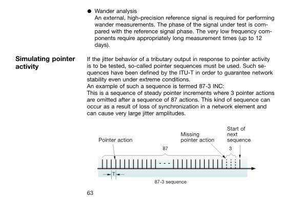
Simulating pointeractivity
If the jitter behavior of a tributary output in response to pointer activityis to be tested, so-called pointer sequences must be used. Such se-quences have been defined by the ITU-T in order to guarantee networkstability even under extreme conditions.An example of such a sequence is termed 87-3 INC:This is a sequence of steady pointer increments where 3 pointer actionsare omitted after a sequence of 87 actions. This kind of sequence canoccur as a result of loss of synchronization in a network element andcan cause very large jitter amplitudes.
Start ofMissing next
Pointer action pointer action sequence
87 3
T
87-3 sequence
63
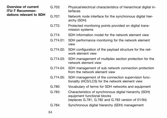
Overview of currentITU-T Recommen-dations relevant to SDH
G.703: Physical/electrical characteristics of hierarchical digital in-terfaces
G.707: Network node interface for the synchronous digital hier-archy (SDH)
G.772: Protected monitoring points provided on digital trans-mission systems
G.774: SDH information model for the network element view
G.774.01: SDH performance monitoring for the network elementview
G.774.02: SDH configuration of the payload structure for the net-work element view
G.774.03: SDH management of multiplex section protection for thenetwork element view
G.774.04: SDH management of sub network connection protectionfrom the network element view
G.774.05: SDH management of the connection supervision func-tionality (HCS/LCS) for the network element view
G.780: Vocabulary of terms for SDH networks and equipment
G.783: Characteristics of synchronous digital hierarchy (SDH)equipment functional blocks(replaces G.781, G.782 and G.783 version of 01/94)
G.784: Synchronous digital hierarchy (SDH) management
64
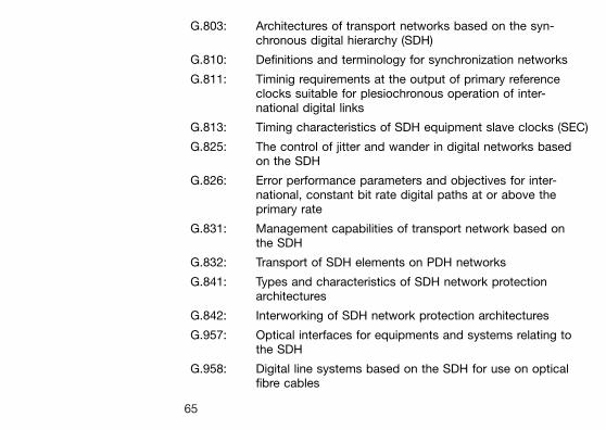
G.803: Architectures of transport networks based on the syn-chronous digital hierarchy (SDH)
G.810: Definitions and terminology for synchronization networks
G.811: Timinig requirements at the output of primary referenceclocks suitable for plesiochronous operation of inter-national digital links
G.813: Timing characteristics of SDH equipment slave clocks (SEC)
G.825: The control of jitter and wander in digital networks basedon the SDH
G.826: Error performance parameters and objectives for inter-national, constant bit rate digital paths at or above theprimary rate
G.831: Management capabilities of transport network based onthe SDH
G.832: Transport of SDH elements on PDH networks
G.841: Types and characteristics of SDH network protectionarchitectures
G.842: Interworking of SDH network protection architectures
G.957: Optical interfaces for equipments and systems relating tothe SDH
G.958: Digital line systems based on the SDH for use on opticalfibre cables
65
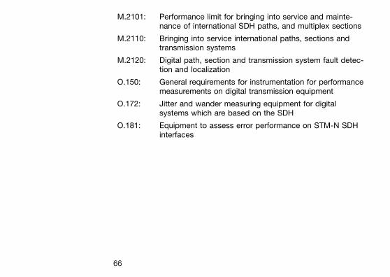
M.2101: Performance limit for bringing into service and mainte-nance of international SDH paths, and multiplex sections
M.2110: Bringing into service international paths, sections andtransmission systems
M.2120: Digital path, section and transmission system fault detec-tion and localization
O.150: General requirements for instrumentation for performancemeasurements on digital transmission equipment
O.172: Jitter and wander measuring equipment for digitalsystems which are based on the SDH
O.181: Equipment to assess error performance on STM-N SDHinterfaces
66
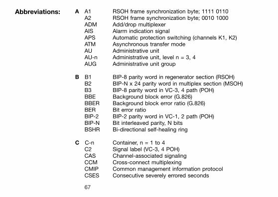
Abbreviations: A A1 RSOH frame synchronization byte; 1111 0110A2 RSOH frame synchronization byte; 0010 1000ADM Add/drop multiplexerAIS Alarm indication signalAPS Automatic protection switching (channels K1, K2)ATM Asynchronous transfer modeAU Administrative unitAU-n Administrative unit, level n = 3, 4AUG Administrative unit group
B B1 BIP-8 parity word in regenerator section (RSOH)B2 BIP-N x 24 parity word in multiplex section (MSOH)B3 BIP-8 parity word in VC-3, 4 path (POH)BBE Background block error (G.826)BBER Background block error ratio (G.826)BER Bit error ratioBIP-2 BIP-2 parity word in VC-1, 2 path (POH)BIP-N Bit interleaved parity, N bitsBSHR Bi-directional self-healing ring
C C-n Container, n = 1 to 4C2 Signal label (VC-3, 4 POH)CAS Channel-associated signalingCCM Cross-connect multiplexingCMIP Common management information protocolCSES Consecutive severely errored seconds
67
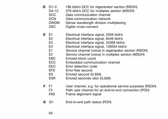
D D1±3 196 kbit/s DCC for regenerator section (RSOH)D4±12 576 kbit/s DCC for multiplex section (MSOH)DCC Data communication channelDCN Data communication networkDWDM Dense wavelength division multiplexingDXC Digital cross-connect
E E1 Electrical interface signal, 2048 kbit/sE2 Electrical interface signal, 8448 kbit/sE3 Electrical interface signal, 34368 kbit/sE4 Electrical interface signal, 139264 kbit/sE1 Service channel (voice) in regenerator section (RSOH)E2 Service channel (voice) in multiplex section (MSOH)EBC Errored block countECC Embedded communication channelEDC Error detection codeEFS Error-free secondES Errored second (G.826)ESR Errored seconds ratio (G.826)
F F1 User channel, e.g. for operational service purposes (RSOH)F2 Path user channel for an end-to-end connection (POH)FAS Frame alignment signal
G G1 End-to-end path status (POH)
68
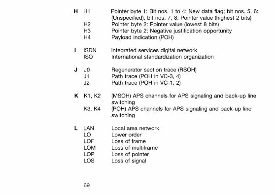
H H1 Pointer byte 1: Bit nos. 1 to 4: New data flag; bit nos. 5, 6:(Unspecified), bit nos. 7, 8: Pointer value (highest 2 bits)
H2 Pointer byte 2: Pointer value (lowest 8 bits)H3 Pointer byte 2: Negative justification opportunityH4 Payload indication (POH)
I ISDN Integrated services digital networkISO International standardization organization
J J0 Regenerator section trace (RSOH)J1 Path trace (POH in VC-3, 4)J2 Path trace (POH in VC-1, 2)
K K1, K2 (MSOH) APS channels for APS signaling and back-up lineswitching
K3, K4 (POH) APS channels for APS signaling and back-up lineswitching
L LAN Local area networkLO Lower orderLOF Loss of frameLOM Loss of multiframeLOP Loss of pointerLOS Loss of signal
69
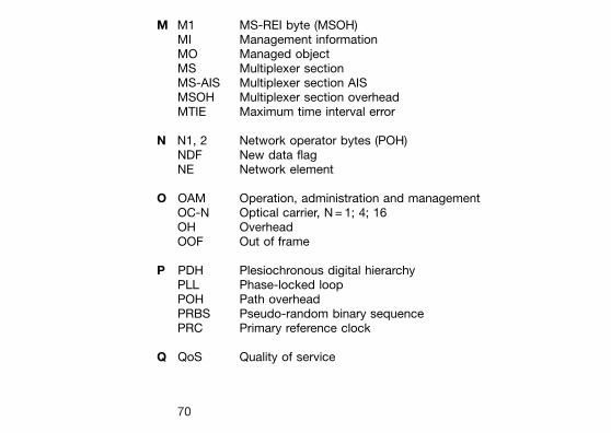
M M1 MS-REI byte (MSOH)MI Management informationMO Managed objectMS Multiplexer sectionMS-AIS Multiplexer section AISMSOH Multiplexer section overheadMTIE Maximum time interval error
N N1, 2 Network operator bytes (POH)NDF New data flagNE Network element
O OAM Operation, administration and managementOC-N Optical carrier, N = 1; 4; 16OH OverheadOOF Out of frame
P PDH Plesiochronous digital hierarchyPLL Phase-locked loopPOH Path overheadPRBS Pseudo-random binary sequencePRC Primary reference clock
Q QoS Quality of service
70
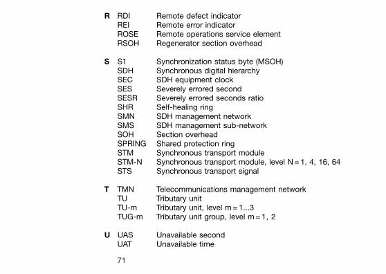
R RDI Remote defect indicatorREI Remote error indicatorROSE Remote operations service elementRSOH Regenerator section overhead
S S1 Synchronization status byte (MSOH)SDH Synchronous digital hierarchySEC SDH equipment clockSES Severely errored secondSESR Severely errored seconds ratioSHR Self-healing ringSMN SDH management networkSMS SDH management sub-networkSOH Section overheadSPRING Shared protection ringSTM Synchronous transport moduleSTM-N Synchronous transport module, level N = 1, 4, 16, 64STS Synchronous transport signal
T TMN Telecommunications management networkTU Tributary unitTU-m Tributary unit, level m = 1...3TUG-m Tributary unit group, level m = 1, 2
U UAS Unavailable secondUAT Unavailable time
71
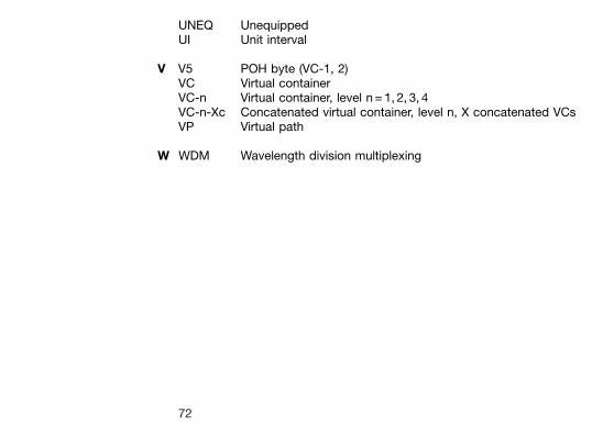
UNEQ UnequippedUI Unit interval
V V5 POH byte (VC-1, 2)VC Virtual containerVC-n Virtual container, level n = 1, 2, 3, 4VC-n-Xc Concatenated virtual container, level n, X concatenated VCsVP Virtual path
W WDM Wavelength division multiplexing
72
Related Documents
![SDH Pocket Guide - Acterna[1]](https://static.cupdf.com/doc/110x72/5529110d5503464d2e8b45f8/sdh-pocket-guide-acterna1.jpg)