ScopeDome.com 2010 Slupsk - Poland sky observatory ver. 1.1 Hereby user guide describes, step by step, all the operations to be accomplished for ScopeDome proper assembling. The manufacturer recommends to set-up the dome according to the procedure hereby referred. Mounting the dome in recommended sequence ensures efficient dome's operation and - at the same time - allows avoiding unnecessary steps and waste of time when fitting-up the dome. The assembly for ScopeDome instructions

Welcome message from author
This document is posted to help you gain knowledge. Please leave a comment to let me know what you think about it! Share it to your friends and learn new things together.
Transcript
ScopeDome.com2010 Slupsk - Poland
sky observatory
ver. 1.1
Hereby user guide describes, step by step, all the operations to be accomplished for ScopeDome proper assembling. The manufacturer recommends to set-up the dome according to the procedure hereby referred. Mounting the dome in recommended sequence ensures efficient dome's operation and - at the same time - allows avoiding unnecessary steps and waste of time when fitting-up the dome.
The assemblyfor ScopeDome
instructions

ScopeDome.com2010 Slupsk - Poland
Necessary tools for dome’s montage
1. Crane (min. 300 kg load)2. Ladder (~5m)3. Mounting platform4. Assurance ropes for positioning the dome's elements5. Automatic screwdriver6. Hexagonal keys (2 sets)7. Driller and drill bits8. Universal meter9. Knife for wires cutting10. At least 5 man for positioning the dome's elements
E
page 2
EN
A
C
B
I
D
F
5 5
6
6
7
7
881
1
2
2
3
3
44
Front panel
A
B
C
D
E
F
H
G
I
Assembly preparation.
1. Make sure you have all dome's parts and suitable tools.2. Prepare the place for dome's assembling. You will need a flat place, aprox.8.0x8.0m.
How to start
Work schedule
Mounting the dome takes about 4 working days:1. Preparing to assembly, checking the
documentation, following steps planing, doubts dispelling.
2.Unloading the dome, checking its parts, preparing construction site.
3.Base ring montage, cog-rim plate and the shutter installation.
4.Main fiber glass dome's parts montage.
Actions sequence
1. Read the manual with understanding2. Install the base ring3. Install the cog-rim plate4. Screw on trolleys to the shutter and brackets of side
rolls of the shutter5. Screw on the blue collar to the cog-rim plate6. Level and center the cog-rim plate7. Check if the cog-rim plate moves easily 8. Screw on all fiber glass panels of the dome with the
cog-rim plate 9. Place the shutter on its right place in the dome's
construction10. Screw on side rolls of the shutter11. Check if the shutter opens and closes easily12. Install azimuth and shutter's driving systems, home
sensor, encoder and its cleaning tape, limit switches, inserters, shutters connecting box, ScopeDome Card
13. Connect all elements according to the diagram14. Check limit switches functioning15. Install controlling software
Check the pictures on CD ROM
Every picture is worth more than 1000 words. Before mounting see the pictures on CD ROM. Look at them in directory: Mounting manual Picture
Fig. 1. The dome's diagram front viewA. Front left sideB. Rear left sideC. Middle left sideD. Front right sideE. Rear right sideF. Middle right sideG. ShutterH. Rear panelI. Front panelK. Apron collar
Fig. 2. The dome's diagram top view, numeration of elements
K

ScopeDome.com2010 Slupsk - Poland
Common solutions
Due to the dome's size the key question is wind resistance. It depenns on the proper attaching the base ring to the observatory's ring beam. Huge volume of the dome returns a special and serious approach to this problem. Keeping all recommendations as for common roofs, is essential. Following drawings show solutions recommended by us.
Mounting the base ring to the observatory's ring beam
Fig. 3. Common solutions
Fig. 4. Other solutions
page 3
base ring
Common(the best)solution
dome roll
cog-rim plate
Dome
Observatory wall
base ring
Solution for concrete
wall
dome roll
cog-rim plate
Dome
EN
Other solutions
We present other possible solutions of fasting the dome on attached CD ROM. If any of these do not satisfy you please, contact us immediately. We may propose some optimal solutions adapted to your architectural plans.
Mounting the base ring to the observatory's ring beam
Observatory creation starts from attachment onto the observatory's crown. It is the main element of the observatory, it determines its wind speed protection. Unfortunately we usually do not know how you have solved this problem. We attach a diagram showing how to do it. You possibly may need special elements to place the base ring onto the observatory's ring beam. It is worth to order them before mounting the dome.
Base ring (including rolls and sides supports) provisionally mounted will be delivered in three or six parts to make assembling easier. The parts of the base ring have to be screwed on in such way to be as round as possible. We recommend to do it directly on the observatory's crown. After centering, the base ring has to be attached to the observatory's ring beam according to Base Ring Attachment.pdf
the base ring
anchor bolt
Observatory ring beam
Observatory wall
apron collar
fastening steel plate
anchor bolt
Apron collar
ScopeDome.com2010 Slupsk - Poland
Numbering of elements
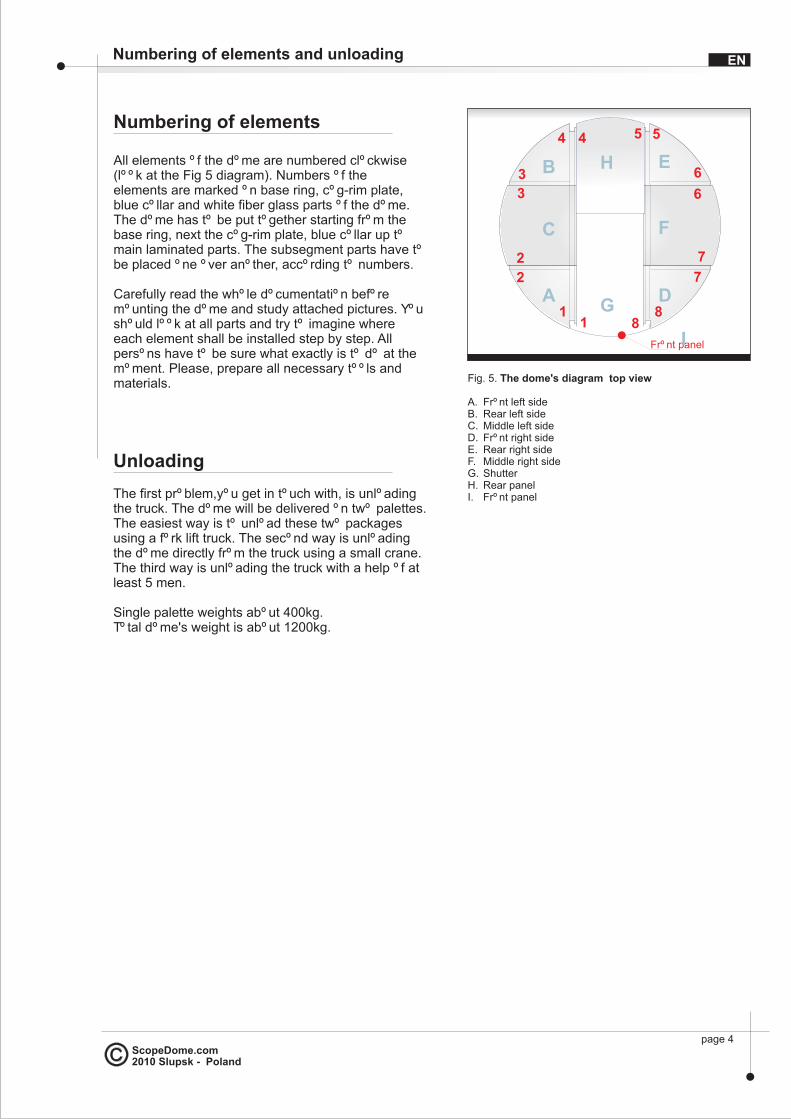
All elements of the dome are numbered clockwise (look at the Fig 5 diagram). Numbers of the elements are marked on base ring, cog-rim plate, blue collar and white fiber glass parts of the dome. The dome has to be put together starting from the base ring, next the cog-rim plate, blue collar up to main laminated parts. The subsegment parts have to be placed one over another, according to numbers.
Carefully read the whole documentation before mounting the dome and study attached pictures. You should look at all parts and try to imagine where each element shall be installed step by step. All persons have to be sure what exactly is to do at the moment. Please, prepare all necessary tools and materials.
ENNumbering of elements and unloading
page 4
5 5
6
6
7
7
881
1
2
2
3
3
44
Front panel
A
B
C
D
E
F
H
G
I
Unloading
The first problem,you get in touch with, is unloading the truck. The dome will be delivered on two palettes. The easiest way is to unload these two packages using a fork lift truck. The second way is unloading the dome directly from the truck using a small crane. The third way is unloading the truck with a help of at least 5 men.
Single palette weights about 400kg. Total dome's weight is about 1200kg.
Fig. 5. The dome's diagram top view
A. Front left sideB. Rear left sideC. Middle left sideD. Front right sideE. Rear right sideF. Middle right sideG. ShutterH. Rear panelI. Front panel

ScopeDome.com2010 Slupsk - Poland
Base ring montage
Successive steps of assembly are shown on figures from Base_Ring_0.pdf to Base_Ring_5.pdf.
Base ring installation shall start with placing its 12 parts on the observatory's ring beam. The next step is screwing on all these parts using bolts and positioning plates to obtain as perfect circle as you can do (fig. 7. element H). To screw on the base ring use M6x15 bolts. Minimum accuracy of the base ring's screwing should be about 3cm (difference between an ellipse axis' lenght).
The next step is screwing on the dome's leading rolls to the base ring. Leading rolls are initially attached to the base ring by us. Next you shall screw on supports of the side movement limiters (fig. 10, element G). Because of need to regulate side movement limiters' height (fig. 10, element H), you shall not screw on the bolts connecting both elements. At the beginning you can screw on G and H elements using only two bolts.
You can screw on the base ring and cog-rim plate simultaneously. Fully mounted base ring and cog-rim plate (after regulation all shifts of side movement limiters) can be attached to the observatory's ring beam permanently.
Base ring montage EN
page 5
A
B
D
E
C
FG
H
M6x15
M10x30
A
B
D
E
C
FG
M6x40
Fig. 6.
A. DomeB. Outer blue collarC. Cog-rim plateD. Observatory's ring beam (concrete)E. Base ringF. Inner blue collarG. Dome's roll
Fig. 7.
A. DomeB. Outer blue collarC. Cog-rim plateD. Observatory's ring beam (concrete)E. Base ringF. Inner blue collarG. Rotating plate mounting bracketH. Base ring mounting bracket

ScopeDome.com2010 Slupsk - Poland
Rotating rolls l
After the base ring is permamently attached to the observatory's ring beam there is a need to level the cog-rim plate accurately. It is very important and a key to correct operation of the dome's rotation driving system. Leveling the cog-rim plate shall be done by using regulation bolts (fig. 10, element G). After precise leveling, the dome shall move round by one hand. All leading rolls shall be strongly subtended to the cog-rim plate. After the dome's assembled, additional regulation of the leading rolls is nessesary, due to their shift after loading full dome's weight.
eveling
ENRotating rolls leveling
page 6
Rys. 9A. Base ringB. Observatory ring beam (concrete)
Fig. 8A. Base ringB. Base ring mounting plateC. Dome RollD. Centering bracket mounting plateE. Centering bracket A
B
AC
D
EB
ScopeDome.com2010 Slupsk - Poland
Cog-rim assembly
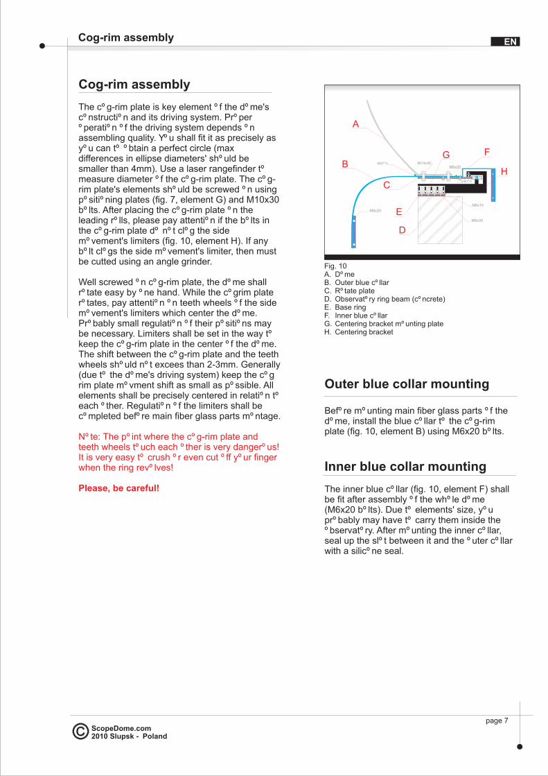
The cog-rim plate is key element of the dome's construction and its driving system. Proper operation of the driving system depends on assembling quality. You shall fit it as precisely as you can to obtain a perfect circle (max differences in ellipse diameters' should be smaller than 4mm). Use a laser rangefinder to measure diameter of the cog-rim plate. The cog-rim plate's elements should be screwed on using positioning plates (fig. 7, element G) and M10x30 bolts. After placing the cog-rim plate on the leading rolls, please pay attention if the bolts in the cog-rim plate do not clog the side movement's limiters (fig. 10, element H). If any bolt clogs the side movement's limiter, then must be cutted using an angle grinder.
Well screwed on cog-rim plate, the dome shall rotate easy by one hand. While the cogrim plate rotates, pay attention on teeth wheels of the side movement's limiters which center the dome. Probably small regulation of their positions may be necessary. Limiters shall be set in the way to keep the cog-rim plate in the center of the dome. The shift between the cog-rim plate and the teeth wheels should not excees than 2-3mm. Generally (due to the dome's driving system) keep the cog rim plate movment shift as small as possible. All elements shall be precisely centered in relation to each other. Regulation of the limiters shall be completed before main fiber glass parts montage.
Note: The point where the cog-rim plate and teeth wheels touch each other is very dangerous! It is very easy to crush or even cut off your finger when the ring revolves!
Please, be careful!
ENCog-rim assembly
page 7
silicon
A
B
D
E
C
FG
HM14x40
M6x20
M6x15
M6x35
M6x20
Fig. 10A. DomeB. Outer blue collarC. Rotate plateD. Observatory ring beam (concrete)E. Base ringF. Inner blue collarG. Centering bracket mounting plateH. Centering bracket
silicon
Outer blue collar mounting
Before mounting main fiber glass parts of the dome, install the blue collar to the cog-rim plate (fig. 10, element B) using M6x20 bolts.
Inner blue collar mounting
The inner blue collar (fig. 10, element F) shall be fit after assembly of the whole dome (M6x20 bolts). Due to elements' size, you probably may have to carry them inside the observatory. After mounting the inner collar, seal up the slot between it and the outer collar with a silicone seal.

ScopeDome.com2010 Slupsk - Poland
Dome’s main parts assembly The dome can be divided in four main sections: sides, front, rear panel and the shutter. It seems that in AMOS case there will be better to orientate the dome's front towards the observatory's roof direction. It will make access to the shutter easier. The shutter should be supported by a wooden bracket during montage.
ENThe dome's side mounting sequence
page 8
Fig. 11. The dome's side mounting sequence
11
2
3
44
A
B
Fig. 13. A-C, B-C elements connecting diagram
A B
C C
M8x35
silicon silicon
1
2
2
3
3
4
C
B
4
A
1
The dome's side mounting sequence
Left part of the dome elements A, B and C
Assembly shall be start at placing A and B elements on the cog-rim plate (after instaling the inner blue collar). Combined surfaces A/B and B/C should be pasted using SIKA glue (fig. 13, silicone gel) before screwing on. The point of contact between elements A, B, C and the cog rim plate shall be pasted in similar way (fig. 10, silicone gel). This shall strengthen the whole construction and make it more water- and wind proof (it is important due to possible extreme weather conditions in high mountains). Using special handles attached to the fiber glass elements A and B, you can put up every part of the dome by a crane and place it on the right position on the observatory's crown according to numeration. Assembling holes shall match each other. If these holes have some shift, simply drill them off a little bit. The next step is screwing on combined A/B parts to the cog rim plate using M14x40 bolts (fig. 10).
After that the C element should be put up by crane and placed on destination. Probably due to its shape at upper sealing connector, it may be the most difficult operation during the whole assembly process. During this operation some help of a few man will be needed. When fitting this element shall be slightly stretched to fit the connector in the upper part of the dome (please do not maind some crashes of the fiber glass parts). In case of bigger problems the upper sealing connector can be simply cutt off and the place where A/C and B/C elements are connected should be sealed using any tape and silicone. It has no influence on the construction's toughness. It helps only to seal the upper part of the dome. Combined elements A, B and C should be screwed on their edges using M8x35 bolts (fig. 13).
Fig. 12. The dome's side mounting sequence

ScopeDome.com2010 Slupsk - Poland
Right part of the dome elements D, E and F
Elements D, E and F should be screwed on in similar way to A, B and C. Before installing the rear panel of the dome, you shall place special bracket which will keep correct distance between left and right sides of the dome (fig. 14).
The domes' sides have a small tendency to fall down into the center of the dome. This may disturb fitting the rear panel. Setting the dome's sides in correct position is possible thanks to special bracket, which shall be placed before rear panel assembly. Distance between sides shall stay around 162.7cm (fig. 15).
Front and rear panel assembly EN
page 9
A D
I
expanding bracket
Fig. 14. Expanding bracket
162.7 cm
B E
Fig. 15. Placing the expanding bracket
162.7 cm
expandingbracket
Rear panel element H
After both sides of the dome next step is fitting rear panel. Using a crane the H element shall be put up and placed on its final position. Before permanent mounting use silicone seal (SIKA) to paste B, E and H elements. The same operation shall proceed in the point of contact H element with the cog-rim plate. After putting on H element shall be screwed on to the cog rim plate at first. After that it can be screwed to B and E elements
assembling the
Front panel element I
This stage of assembly shall proceed in similar way as the rear panel.
ScopeDome.com2010 Slupsk - Poland
Shutter assemby - element G
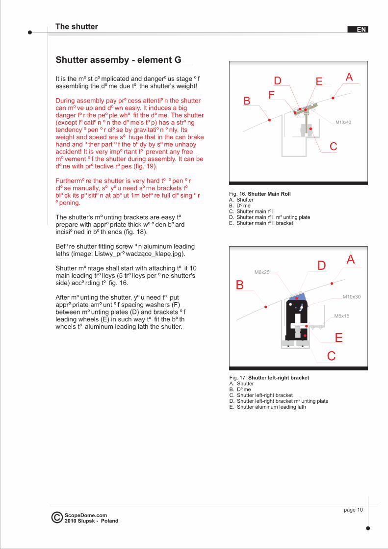
It is the most complicated and dangerous stage of assembling the dome due to the shutter's weight!
The shutter's mounting brackets are easy to prepare with appropriate thick wooden board incisioned in both ends (fig. 18).
Before shutter fitting screw on aluminum leading laths (image: Listwy_prowadz¹ce_klapê.jpg).
Shutter montage shall start with attaching to it 10 main leading trolleys (5 trolleys per one shutter's side) according to fig. 16.
After mounting the shutter, you need to put appropriate amount of spacing washers (F) between mounting plates (D) and brackets of leading wheels (E) in such way to fit the both wheels to aluminum leading lath the shutter.
During assembly pay process attention the shutter can move up and down easly. It induces a big danger for the people who fit the dome. The shutter (except location on the dome's top) has a strong tendency open or close by gravitation only. Its weight and speed are so huge that in the can brake hand and other part of the body by some unhapy accident! It is very important to prevent any free movement of the shutter during assembly. It can be done with protective ropes (fig. 19).
Furthermore the shutter is very hard to open or close manually, so you need some brackets to block its position at about 1m before full closing or opening.
A
B
C
D EF
M10x40
Fig. 16. Shutter Main RollA. ShutterB. DomeC. Shutter main rollD. Shutter main roll mounting plateE. Shutter main roll bracket
A
B
C
D
E
M5x15
M6x25
Fig. 17. Shutter left-right bracketA. ShutterB. DomeC. Shutter left-right bracketD. Shutter left-right bracket mounting plateE. Shutter aluminum leading lath
M10x30
The shutter EN
page 10

ScopeDome.com2010 Slupsk - Poland
Shutter assemby
The next step is to attach 6 mounting plates (trolleys left/right) to the shutter 3 plates per side (fig. 17, element D).
Left-right shutter brackets shall be overthrusted on aluminum laths - 3 brackets per side. The most convenient way is placing two brackets on the ends of aluminum laths before mounting the shutter, one in front and one in the back of the dome (fig. 17, element C).
The shutter with initially mounted trolleys shall be put on the dome by a crane and with help of at least 4 man (fig. 19)
After this operation the shutter shall easly move on the dome. It is necessary to block it by ropes. Movement of the shutter has to be carefully controlled using ropes or stabilizing brackets in its extreme positions.
The following step is screwing on left-right shutter brackets to suitable mounting plates (fig. 17, element C).
After checking that the shutter moves easly, the brackets and assurance ropes can be removed and the shutter can be slightly closed next.
Principally this is the end of the dome assembly. Now, you shall only install azimuth and shutter's driving systems and the necessary electrical wiring.
A
B
C
Fig. 18. Shutter assembly bracketA. ShutterB. Front panelC. Special wood bracket
A
B
C
D
Fig. 19. Shutter securityA. ShutterB. DomeC. CraneD. Shutter positioning and security rope
page 11
The shutter EN

ScopeDome.com2010 Slupsk - Poland
page 12
Additionally dome protect against a strong wind
What can be done in additionto protect the dome againststrong wind?
The dome will be installed in high mountains and for that reason sometimes will work in very hard weather conditions. It is recommended to introduce additional actions to protect it from extremely winds (over 100 km/h). These kind of solutions are very hard to automatic without disproportional costs.
After mounting the dome simple follow weather forecasts. If very strong winds are forecast there is a need, in our opinion, to introduce additional reinforcements using pure mechanics.
First, take care about additional shutter's protection against its detaching by extremely strong wind gusts. The simplest solution is to add two big bolts on the edges of the shutter (connecting it with the dome) manually inserted and removed in case of to unfavorable forecasts.
You can design some rotating clamps (easy to use) which will permanently hold the shutter onto the observational window's edge. Obviously then will be no possibility of remote open without unblocking the window manually. We work on such solution now and we are going to add this support to the new version of our ScopeDome USB Card with dedicated sensors.
The next idea is additional reinforcement for rotating part of the dome fixed to the observatory's crown. The best solution seems to be durable clamps, merging the dome (or the cog-rim plate) with the ring beam.
EN
ScopeDome.com2010 Slupsk - Poland
Dome automatics- introduction
Introduction
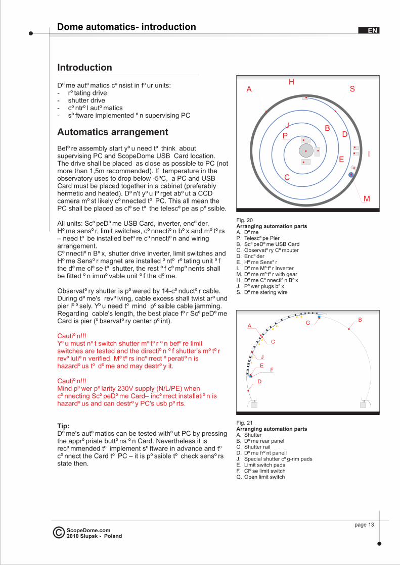
Dome automatics consist in four units:- rotating drive- shutter drive- control automatics- software implemented on supervising PC
Automatics arrangement
Before assembly start you need to think about supervising PC and ScopeDome USB Card location. The drive shall be placed as close as possible to PC (not more than 1,5m recommended). If temperature in the observatory uses to drop below -5oC, a PC and USB Card must be placed together in a cabinet (preferably hermetic and heated). Don't you forget about a CCD camera most likely connected to PC. This all mean the PC shall be placed as close to the telescope as possible.
All units: ScopeDome USB Card, inverter, encoder, Home sensor, limit switches, connection box and motors – need to be installed before connection and wiring arrangement.Connection Box, shutter drive inverter, limit switches and Home Sensor magnet are installed onto rotating unit of the dome close to shutter, the rest of components shall be fitted on immovable unit of the dome.
Observatory shutter is powered by 14-conductor cable. During dome's revolving, cable excess shall twist around pier loosely. You need to mind possible cable jamming. Regarding cable's length, the best place for ScopeDome Card is pier (observatory center point).
Tip:Dome's automatics can be tested without PC by pressing the appropriate buttons on Card. Nevertheless it is recommended to implement software in advance and to connect the Card to PC – it is possible to check sensors state then.
Caution!!!You must not switch shutter motor on before limit switches are tested and the direction of shutter's motor revolution verified. Motors incorrect operation is hazardous to dome and may destroy it.
Caution!!!Mind power polarity 230V supply (N/L/PE) when connecting ScopeDome Card– incorrect installation is hazardous and can destroy PC's usb ports.
Fig. 20 Arranging automation partsA. DomeP. Telescope PierB. ScopeDome USB CardC. Observatory ComputerD. EncoderE. Home SensorI. Dome Motor InverterM. Dome motor with gearH. Dome Connection BoxJ. Power plugs boxS. Dome stering wire
Fig. 20 Arranging automation partsA. DomeP. Telescope PierB. ScopeDome USB CardC. Observatory ComputerD. EncoderE. Home SensorI. Dome Motor InverterM. Dome motor with gearH. Dome Connection BoxJ. Power plugs boxS. Dome stering wire
B
C
P
M
D
E
A
I
H
J
S
Fig. 21Arranging automation partsA. ShutterB. Dome rear panelC. Shutter railD. Dome front panellJ. Special shutter cog-rim padsE. Limit switch padsF. Close limit switchG. Open limit switch
Fig. 21Arranging automation partsA. ShutterB. Dome rear panelC. Shutter railD. Dome front panellJ. Special shutter cog-rim padsE. Limit switch padsF. Close limit switchG. Open limit switch
1
1
2
2
33
4 4
A
C
B
J
D
EF
G
EN
page 13

ScopeDome.com2010 Slupsk - Poland
Routine
Rotating drive1. Install ScopeDome USB Card, inverter, encoder and
Home Sensor.2. Fix dome's rotating motor3. Adjust drive's cog-rim height4. Connect wiring5. Test rotating drive
Shutter drive6. Fix side supports of main beam for shutter drive7. Screw on the beam with its side supports8. Install the shutter motor. Beware, gear-wheel must
not touch guide rails9. Fix ScopeDome USB Card, inverter, encoder and
Home Sensor, install limit switches, switches clamp plate, inverter and Connection Box with ScopeDome Card.
10. Plug wiring of motor, inverter and limit switches, then connect ScopeDome Card with connection box.
11. Check up if the limit switches work properly and verify direction of shutter's motor revolution.
12. Set shutter motor so that gear-wheels are fixed tightly to guide rail.
13. Test shutter drive operation in Open and Close positions at low motor rev.
Caution!!!Absolutely - review carefully all illustrations and photos on CD attached to the manual (pdf files).
Dome automatics- routine EN
page 14

ScopeDome.com2010 Slupsk - Poland
Rotating Drive
Before plugging driving motor you need to adjust carefully rollers and supports of side motion limiters - the idea is the dome shall revolve without resistance. Supports of motion limiters shall be adjusted so that the dome can revolve centrically on the ring, with some loose (1-2mm). All guiding rollers of the dome shall be firmly tightened to cog-rim. If necessary, adjust theirs height .
Home Sensor and EncoderHome sensor serves to establish dome's zero position. The most convenient way is to install sensor contactron onto one of the dome's side supports (choose the nearest to the ScopeDome Card) and to place the magnet at inner side of cog–rim (fig. 23). The gap between magnet and contactron must not exceed 15mm.
Before motor installation check up if Home Sensor works properly, that is – if contractron contacts get circuit while magnet is passing the sensor (use an omometer or plug ScopeDome Card to PC and read sensors status on main program screen).
Place the encoder which reckon dome's position on the same side support where Home Sensor is fixed. Wheel-gear cogs shall pass through inside measurement of encoder sensor, so as one impulse is counted at each cog. Do not insert encoder sensor too deep, preferably fix its end somewhere about middle point of a cog.
Cleaning tape shall be sticked to both sides of the cog-rim. Tape's pile shall clean encoder's sensor while passing it. It prevents dust settlement on the encoder.
Caution!!!Encoder is very fragile and easy to destroy. Pay special attention during installation - in no case cog-rim shall scrape nor catch encoder sensor.
A
B
D
E
C
F
G
W
M
Fig. 22A. DomeB. Outside shieldC. Rotate plateD. Observatory baseE. Base ringF. Inside shieldM. Ra motorG. Ra motor gearW. cog-whell
Fig. 22A. DomeB. Outside shieldC. Rotate plateD. Observatory baseE. Base ringF. Inside shieldM. Ra motorG. Ra motor gearW. cog-whell
M6x20M10x35
A
B
C
Fig. 23A. DomeB. Outside shieldC. Rotate plateD. EncoderE. Home SensorH. Centering bracket
Fig. 23A. DomeB. Outside shieldC. Rotate plateD. EncoderE. Home SensorH. Centering bracket
D
Hmagnet
E
Dome automatics- Rotating Drive EN
page 15
home
ScopeDome.com2010 Slupsk - Poland
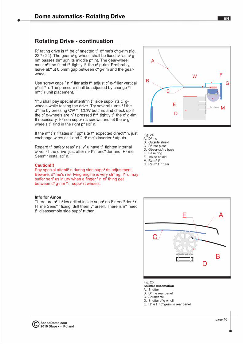
Rotating Drive - continuation
Rotating drive is to be connected to dome's cog-rim (fig. 22 or 24). The gear cog-wheel shall be fixed so as cog-rim passes through its middle point. The gear-wheel must not be fitted to tightly to the cog-rim. Preferably, leave about 0.5mm gap between cog-rim and the gear-wheel.
Use screw caps on roller axis to adjust cog-roller vertical position. The pressure shall be adjusted by change of motor unit placement.
You shall pay special attention to side supports cog-wheels while testing the drive. Try several turns of the dome by pressing CW or CCW buttons and check up if the cog-wheels are not pressed too tightly to the cog-rim. If necessary, loosen supports screws and let the cog-wheels to find in the right position.
If the motor rotates in opposite to expected direction, just exchange wires at 1 and 2 dome's inverter outputs.
Regard to safety reasons, you have to tighten internal cover of the drive just after motor, encoder and Home Sensor installation.
Info for AmosThere are no holes drilled inside supports for encoder or Home Sensor fixing, drill them yourself. There is no need to disassemble side support then.
Caution!!!Pay special attention during side supports adjustment. Beware, dome's revolving engine is very strong. You may suffer serious injury when a finger or clothing get between cog-rim or support wheels.
A
B
D
E
C
F
G
W
M
Fig. 24A. DomeB. Outside shieldC. Rotate plateD. Observatory baseE. Base ringF. Inside shieldM. Ra motorG. Ra motor gear
Fig. 24A. DomeB. Outside shieldC. Rotate plateD. Observatory baseE. Base ringF. Inside shieldM. Ra motorG. Ra motor gear
M10x80
Dome automatics- Rotating Drive
C
BD
E
Fig. 25Shutter AutomationA. ShutterB. Dome rear panelC. Shutter railD. Shutter cog-whellE. Hole for cog-rim in rear panel
A
EN
page 16
ScopeDome.com2010 Slupsk - Poland
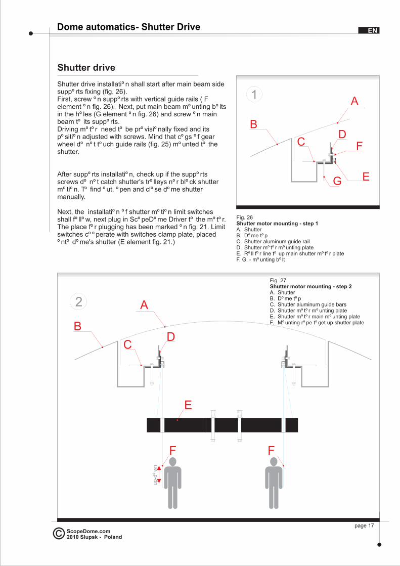
Shutter drive
Shutter drive installation shall start after main beam side supports fixing (fig. 26).First, screw on supports with vertical guide rails ( F element on fig. 26). Next, put main beam mounting bolts in the holes (G element on fig. 26) and screw on main beam to its supports. Driving motor need to be provisionally fixed and its position adjusted with screws. Mind that cogs of gear wheel do not touch guide rails (fig. 25) mounted to the shutter.
After supports installation, check up if the supports screws do not catch shutter's trolleys nor block shutter motion. To find out, open and close dome shutter manually.
Next, the installation of shutter motion limit switches shall follow, next plug in ScopeDome Driver to the motor. The place for plugging has been marked on fig. 21. Limit switches cooperate with switches clamp plate, placed onto dome's shutter (E element fig. 21.)
Dome automatics- Shutter Drive
A
B
CD
1
E
Fig. 26Shutter motor mounting - step 1A. ShutterB. Dome topC. Shutter aluminum guide railD. Shutter motor mounting plateE. Roll for line to up main shutter motor plateF. G. - mounting bolt
A
B
C
2
D
up-d
ow
n
F F
E
EN
page 17
F
G
Fig. 27Shutter motor mounting - step 2A. ShutterB. Dome topC. Shutter aluminum guide barsD. Shutter motor mounting plateE. Shutter motor main mounting plateF. Mounting rope toget up shutter plate

ScopeDome.com2010 Slupsk - Poland
Shutter drive
Test switches operation and shutter motor rotating direction after plugging wires:
- push Close button on ScopeDome Card - motor shall follow shutter shutting direction
- push limit switch Close ( in front of the dome) - the motor shall stop
- push Open button on ScopeDome Card - motor shall rotate to open the shutter
- push limit switch Open (on dome's top) - motor shall stop
If the engine rotates in opposite to expected direction, just exchange wires at 1 and 2 dome's inverter outputs. Limit switches need to be adjusted as to stop the motor 2-3cm before complete shutdown or opening. Preferably, provisionally set switch axis inclination to maximum (as to stop the shutter the most early). Then - only after testing the drive operation, you may change switches position so the shutter stops in proper position. The tests of shutter drive shall be carried out at lowest engine rev (aprox. at 50% of max. speed). Motor rev can be adjusted with an inverter control knob.
After motor rotating direction is checked and limit switches operation inspected, shutter engine may be fixed on its proper place. Using adjustable bolts, lift the engine so the gear wheels get deep (with all its height) into guide rails (fig. 25). Next, lift up the engine again by 2-3 mm so that dome's weight rests on the cog-wheels of shutters drive.
B
C
3
Fig. 28Shutter motor mounting - step 3A. ShutterB. Dome topC. Shutter aluminum guide railsD. Shutter motor mounting plateE. Shutter motor main mounting plate
A
D
E
4 A
B
C
left-right
up-d
ow
n
E
F
WM
H
DG
J
Repeatedly test the effect of the flop in outermost positions (Open and Close).
If the flap works correctly it is end of the mechanical and electric installation of the part of drive of the dome.
Fig. 29Shutter motor mounting - step 4A. ShutterB. Dome topC. Shutter aluminum guide railsD. Shutter motor mounting plateE. Main shutter plate mounting screwF. Shutter motor up-down screwG. GearM. Shutter MotorH. Shutter cog-rimJ. Special shutter guide rails padW. Shutter cog-whell
Shutter Drive - continuation EN
page 18

ScopeDome.com2010 Slupsk - Poland
Dome's wiring system
Most usually our clients accomplish wiring by themselves. You can find some typical wiring schemes on attached CD.
Until you do not have any experience in this sort of wiring work, we recommend to take advantage of some electrician or electric installation service firm (eg. servicing housing etc.). Observatory wiring can be accomplished by any on the firm servicing wiring.
Apart of wiring schemes we can advise as follows:
- mind correct installation of ScopeDome USB Card 230V power supply: it has to be properly connected do electrical zero (N) and to phase (L). Regarding safety, protective wire shall be connected.
- acquaint yourself with observatory diagrams on attached CD
- ScopeDome USB Card Driver has built-in control for common observatory appliances as a telescope, camera, lighting and ventilation. It is worth to provide some essential sockets (connected to ScopeDome Card) to power such equipment
- wires connecting 3-phase dome driving engines and appropriate inverters shall be as short as possible
- supervising PC with ScopeDome Card and all other electronics shall be placed in heated and hermetic cabinet preferably- during the night the temperature often falls below zero °C ; electronics do not "like" low temperatures nor high humidity
- generally there is no need to plug a keyboard nor a monitor to controlling PC (apart of test phase), so it may be closed in a small cabinet; most likely PC's own heat will do. Observatory supervision can be implement by common software for remote access - e.g. VNC Viewer or Team Viewer
- necessary wiring for automatics can be conducted in plastic tubes or in small holes drilled in dome's reinforcements
- if you plan remote access, we strongly recommend to install inner and - preferably, outer CCTV to monitor dome's operation and observatory equipment, especially telescope's mount
Software
Dome's software installation manual is available at www.ScopeDome.com
Dome automatics - Dome's wiring system EN
page 19
Related Documents