SAMSUNG INK-JET MFP SCX-1350F SCX-1300 SERVICE ˘ ‰”‰ˆ ”„» ‰ˆ Manual SAMSUNG INK-JET MFP CONTENTS 1. Precautions 2. Specifications 3. Disassembly and Reassembly 4. Troubleshooting 5. Exploded Views and Parts List 6. Block Diagram

Samsung SCX 1350F and 1300 MFP Service Manual
Oct 23, 2015
Welcome message from author
This document is posted to help you gain knowledge. Please leave a comment to let me know what you think about it! Share it to your friends and learn new things together.
Transcript
SAMSUNG INK-JET MFPSCX-1350FSCX-1300
SERVICE
˘‰”‰ˆ
”„»‰ˆ
Manual
SAMSUNG INK-JET MFP CONTENTS
1. Precautions
2. Specifications
3. Disassembly and Reassembly
4. Troubleshooting
5. Exploded Views and Parts List
6. Block Diagram
PrecautionsService M
anual
Samsung Electrouics
Precautions
1-1
1. Precautions
Follow these safety, ESD, and servicing precautions to prevent personal injury and equipment damage.
1.1 Safety Precautions
1. Be sure that all built-in protective devices are in place. Restore any missing protective shields.2. Make sure there are no cabinet openings through which people- particularly children- might insert fingers or objects and con-
tact dangerous voltages.3. When re-installing chassis and assemblies, be sure to restore all protective devices, including control knobs and compartment covers. 4. Design Alteration Warning : Never alter or add to the mechanical or electrical design of this equipment, such as auxiliary con-
nectors, etc. Such alterations and modifications will void the manufacturer’s warranty.5. Components, parts, and wiring that appear to have overheated or are otherwise damaged should be replaced with parts which
meet the original specifications. Always determine the cause of damage or overheating, and correct any potential hazards.6. Observe the original lead dress, especially near sharp edges, AC, and high voltage power supplies. Always inspect for
pinched, out-of-place, or frayed wiring. Do not change the spacing between components and the printed circuit board. 7. Product Safety Notice : Some electrical and mechanical parts have special safety-related characteristics which might not be
obvious from visual inspection. These safety features and the protection they provide could be lost if a replacement compo-nent differs from the original. This holds true, even though the replacement may be rated for higher voltage, wattage, etc.
Components critical for safety are indicated in the parts list with symbols . Use only replacement components that havethe same ratings, especially for flame resistance and dielectric specifications. A replacement part that does not have the samesafety characteristics as the original may create shock, fire, or other safety hazards.
1.2 ESD Precautions
Certain semiconductor devices can be easily damaged by static electricity. Such components are commonly called“Electrostatically Sensitive (ES) Devices”, or ESDs. Examples of typical ESDs are: integrated circuits, some field effect transistors,and semiconductor “chip” components.The techniques outlined below should be followed to help reduce the incidence of component damage caused by static electricity.
Caution >> Be sure no power is applied to the chassis or circuit, and observe all other safety precautions.
1. Immediately before handling a semiconductor component or semiconductor-equipped assembly, drain off any electrostaticcharge on your body by touching a known earth ground. Alternatively, employ a commercially available wrist strap device,which should be removed for your personal safety reasons prior to applying power to the unit under test.
2. After removing an electrical assembly equipped with ESDs, place the assembly on a conductive surface, such as aluminumor copper foil, or conductive foam, to prevent electrostatic charge buildup in the vicinity of the assembly.
3. Use only a grounded tip soldering iron to solder or desolder ESDs.4. Use only an “anti-static” solder removal device. Some solder removal devices not classified as “anti-static” can generate elec-
trical charges sufficient to damage ESDs.5. Do not use Freon-propelled chemicals. When sprayed, these can generate electrical charges sufficient to damage ESDs.6. Do not remove a replacement ESD from its protective packaging until immediately before installing it. Most replacement ESDs
are packaged with all leads shorted together by conductive foam, aluminum foil, or a comparable conductive material.7. Immediately before removing the protective shorting material from the leads of a replacement ESD, touch the protective mate-
rial to the chassis or circuit assembly into which the device will be installed. 8. Maintain continuous electrical contact between the ESD and the assembly into which it will be installed, until completely
plugged or soldered into the circuit.9. Minimize bodily motions when handling unpackaged replacement ESDs. Normal motions, such as the brushing together of
clothing fabric and lifting one’s foot from a carpeted floor, can generate static electricity sufficient to damage an ESD.
manuals4you.commanuals4you.com
Precautions
1-2
Service Manual
Samsung Electrouics
Precautions
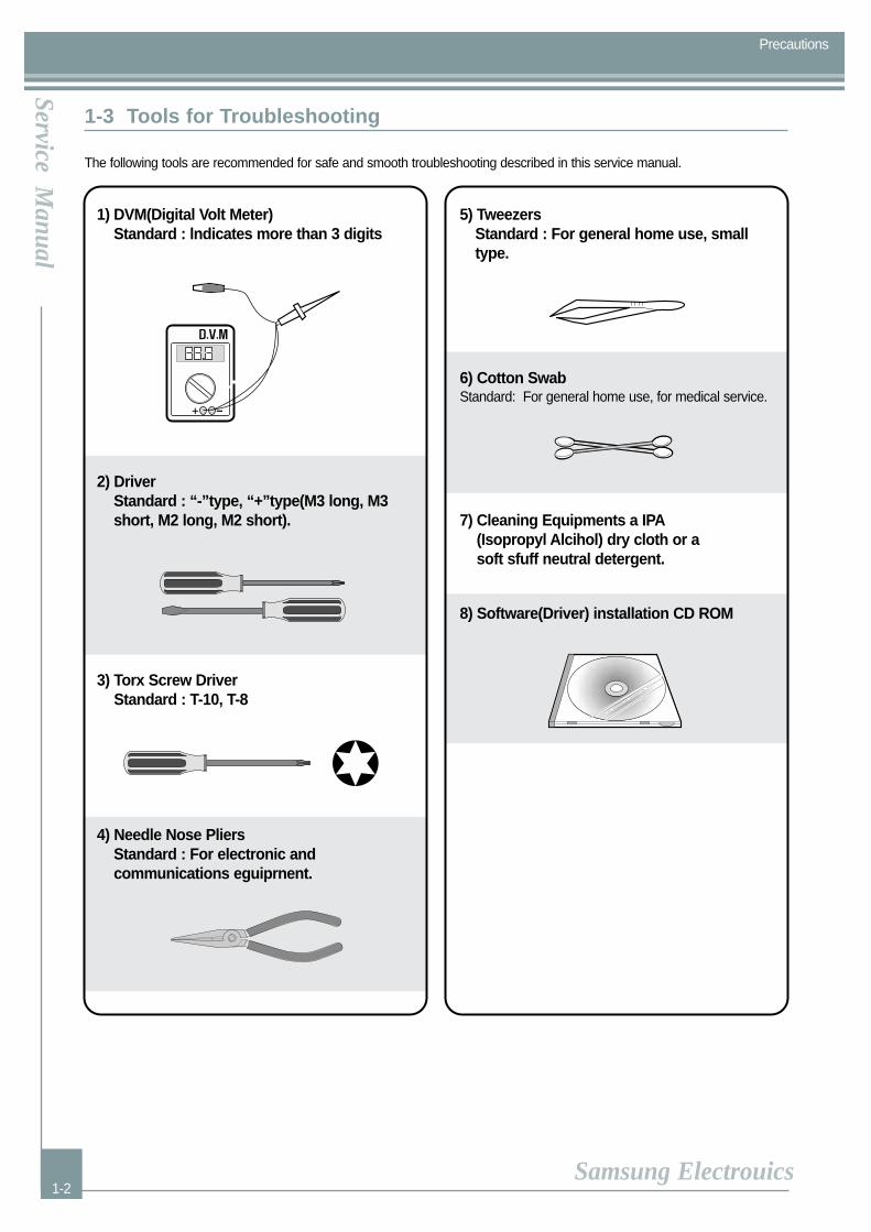
1-3 Tools for Troubleshooting
The following tools are recommended for safe and smooth troubleshooting described in this service manual.
1) DVM(Digital Volt Meter)Standard : lndicates more than 3 digits
2) DriverStandard : “-”type, “+”type(M3 long, M3short, M2 long, M2 short).
3) Torx Screw DriverStandard : T-10, T-8
4) Needle Nose PliersStandard : For electronic and communications eguiprnent.
5) TweezersStandard : For general home use, smalltype.
6) Cotton SwabStandard: For general home use, for medical service.
7) Cleaning Equipments a IPA(Isopropyl Alcihol) dry cloth or asoft sfuff neutral detergent.
8) Software(Driver) installation CD ROM

MemoMemo
manuals4you.commanuals4you.com

2. Specification
Items SCX-1300 SCX-1300F Remark
PrecautionsPrecautionsService M
anual
Samsung Electrouics
Specification
2-1
Print Speed Mono:17 ppm Mono:19 ppm
Color:12 ppm Color:15 ppm
Resolution Mono : 4,800 X 1,200 DPI
Color : 4,800 X 1,200 DPI
Print Method Drop-on demend thermal inkjet printing
OS Compatibility Windows 98,ME,2K,XP
Interface USB 2.0 Full speed(USB 1.1 equivalent)
Dimension 496 X 394 X 212mm 496 X 394 X 300mm
Weight 8.56Kg 10.162Kg
Duty Cycle up to 300 pages per month,maximum
Life Span 36,000 page
Ink Cartridge INK-M90, INK-C90 , INK-P90 Photo Ink:Option
Intput Capacity 150 sheet
Output Capacity 50 sheet
Duplex N/A
Memory 64M
2. Specification
2.1 Product Specifications
INK-M90 INK-C90 INK-P90
Nozzle 416EA 300EA 300EA
Ink Drop Size 16 pi 4.5 pi 5 pi
Ink Color Mono Color(CMY) Color(KMC)
Ink Yield 450 pages 400 pages 125 pages
A4 5% A4 15% A4 15%
2.2 Ink Cartridge
Precautions
2-2
Service Manual
Samsung Electrouics
Specification
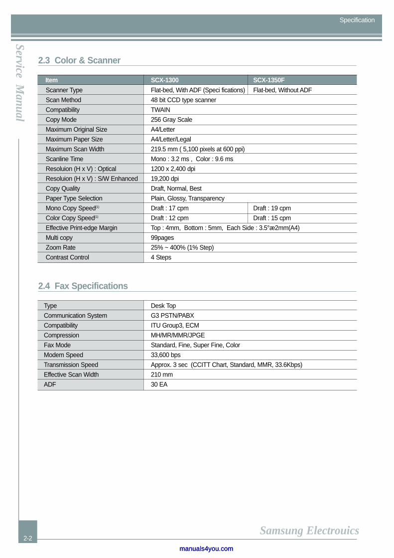
2.3 Color & Scanner
Flat-bed, With ADF (Speci fications) Flat-bed, Without ADF
48 bit CCD type scanner
TWAIN
256 Gray Scale
A4/Letter
A4/Letter/Legal
219.5 mm ( 5,100 pixels at 600 ppi)
Mono : 3.2 ms , Color : 9.6 ms
1200 x 2,400 dpi
19,200 dpi
Draft, Normal, Best
Plain, Glossy, Transparency
Draft : 17 cpm Draft : 19 cpm
Draft : 12 cpm Draft : 15 cpm
Top : 4mm, Bottom : 5mm, Each Side : 3.5°æ2mm(A4)
99pages
25% ~ 400% (1% Step)
4 Steps
Item SCX-1300 SCX-1350F
Scanner Type
Scan Method
Compatibility
Copy Mode
Maximum Original Size
Maximum Paper Size
Maximum Scan Width
Scanline Time
Resoluion (H x V) : Optical
Resoluion (H x V) : S/W Enhanced
Copy Quality
Paper Type Selection
Mono Copy Speed(1)
Color Copy Speed(1)
Effective Print-edge Margin
Multi copy
Zoom Rate
Contrast Control
2.4 Fax Specifications
Type Desk Top
Communication System G3 PSTN/PABX
Compatibility ITU Group3, ECM
Compression MH/MR/MMR/JPGE
Fax Mode Standard, Fine, Super Fine, Color
Modem Speed 33,600 bps
Transmission Speed Approx. 3 sec (CCITT Chart, Standard, MMR, 33.6Kbps)
Effective Scan Width 210 mm
ADF 30 EA
manuals4you.commanuals4you.com
PrecautionsPrecautionsService M
anual
Samsung Electrouics
Specification
2-3
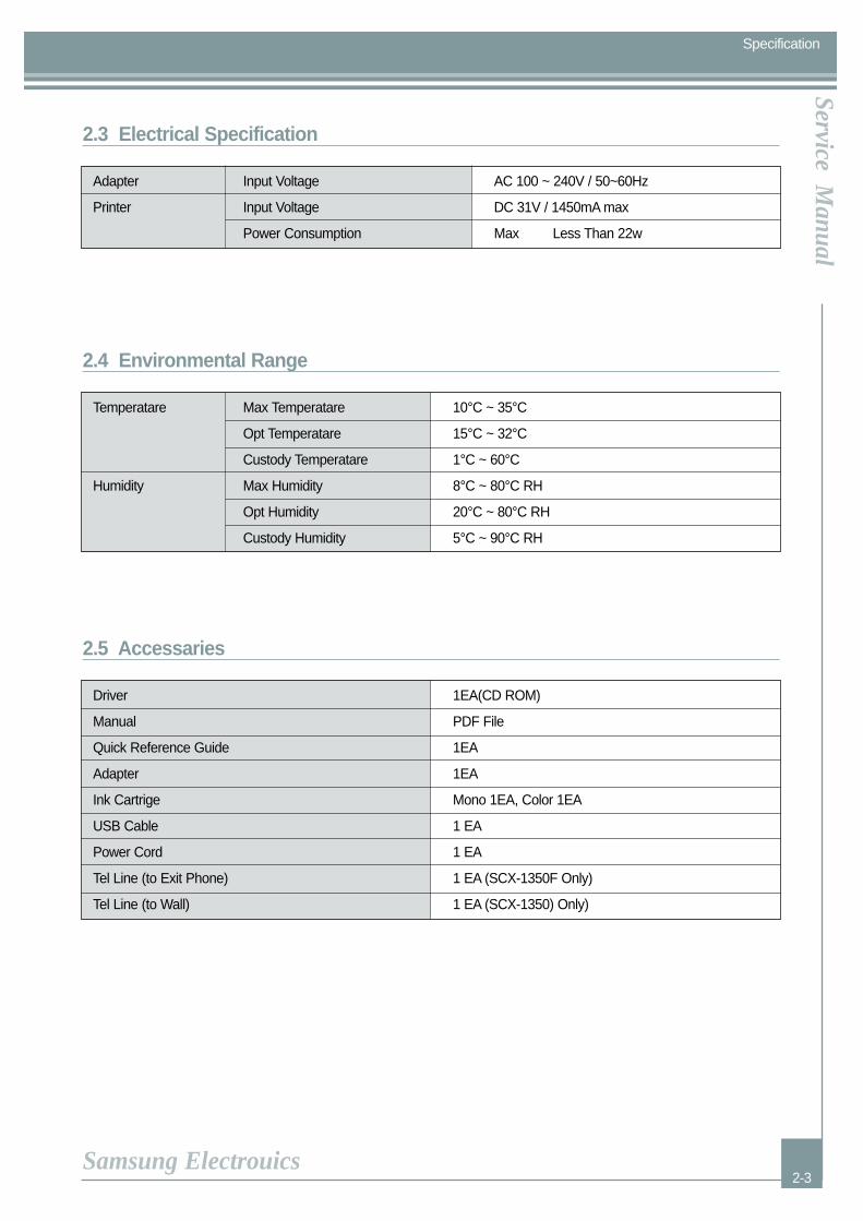
Adapter Input Voltage AC 100 ~ 240V / 50~60Hz
Printer Input Voltage DC 31V / 1450mA max
Power Consumption Max Less Than 22w
2.3 Electrical Specification
Temperatare Max Temperatare 10°C ~ 35°C
Opt Temperatare 15°C ~ 32°C
Custody Temperatare 1°C ~ 60°C
Humidity Max Humidity 8°C ~ 80°C RH
Opt Humidity 20°C ~ 80°C RH
Custody Humidity 5°C ~ 90°C RH
2.4 Environmental Range
Driver 1EA(CD ROM)
Manual PDF File
Quick Reference Guide 1EA
Adapter 1EA
Ink Cartrige Mono 1EA, Color 1EA
USB Cable 1 EA
Power Cord 1 EA
Tel Line (to Exit Phone) 1 EA (SCX-1350F Only)
Tel Line (to Wall) 1 EA (SCX-1350) Only)
2.5 Accessaries

PrecautionsPrecautionsService M
anual
Samsung Electrouics
Disassembly and Reassembly
3-1
3. Disassembly and Procedure
3-1 General Precautions on Disassembly
Required Tools
1. Small Screw Driver.2. Needle Nose Pliers.3. T-10, T-8 Torx screwdriver.4. Lubricant, 6040-1322, when necessary.
When disassemble and reassembling components, use extreme caution. The close proximity of cables to moving partsmakes proper routing a must. If components are removed or replaced, any cables disturbed by the procedure must bereplaced as close as possible to their original positions. Before removing any component from the machine, note the cablerouting that will be affected.
Whenever servicing the machine, you must perform the following:
1. Remove the print cartridge.2. Unplug the power cord.3. Work on a flat and clean surface.4. Replace only with authorized components.5. Do not force plastic components.6. Make sure all components are in their proper position.
Caution about Main PCA service and Mech Assy service.
Mech Assy is built detailed product via minute control at manufacturing process to embody the best productperformance.The cautions in the below are items needed to keep in mind when maintaining and servicing.
* Printer engine prohibits disjointing of parts excepting part parts such as Encoder Srip.* Must achieve work that adjust establishment default value of printer engine and main board after
Main B’d change by new thing necessarily.(Reference: “4.6.2 Media Sensor LTVG Calibration”)
manuals4you.commanuals4you.com

Precautions
3-2
Service Manual
Samsung Electrouics
Disassembly and Reassembly
3-2 Rear Cover
1. Remove the Clean-out Ass'y. Then push theKnob in the drection of arrow, as shown below.
2. Remove the two screws securing the RearCover.
3. Carefully release the Rear Cover latches fromChassis Ass'y and Left Side Cover, RH* in thedirection of arrow, as shown below.
* LF : Left SideRH : Right Side
Knob
Clean-out Ass’y
1
1
2
ˆ
Rear Cover
˘‰”‰ˆ
”„»‰ˆ

PrecautionsPrecautionsService M
anual
Samsung Electrouics
Disassembly and Reassembly
3-3
3-3 Scanner Ass'y (with ADF Ass'y)
1. Before you remove the Scanner Ass'y, youshould remove:- Rear Cover (see chapter 3-2)
2. Open the Scanner Ass'y.
3. Release the two Springs from Door Front, asshown below.
4. Release the Slide Cam from Door Front, asshown below. Then open the Scanner Ass'y.
Note : When the Scanner Ass'y is fully opened,make sure ADF Ass'y doesn't open likebelow. Place ADF Ass'y on CellophaneTape, and make sure it's fixed, beforebreaking apart the assembly.
5. Unplug the two connectors and two Cables(Control Panel, Scanner Module) from MainPCA, as shown below.
ADF Ass'y
Scanner Ass'y
Door Spring
Front Door
Door Spring
Front Door
Front Door
Slide Cam
manuals4you.commanuals4you.com
Precautions
3-4
Service Manual
Samsung Electrouics
Disassembly and Reassembly
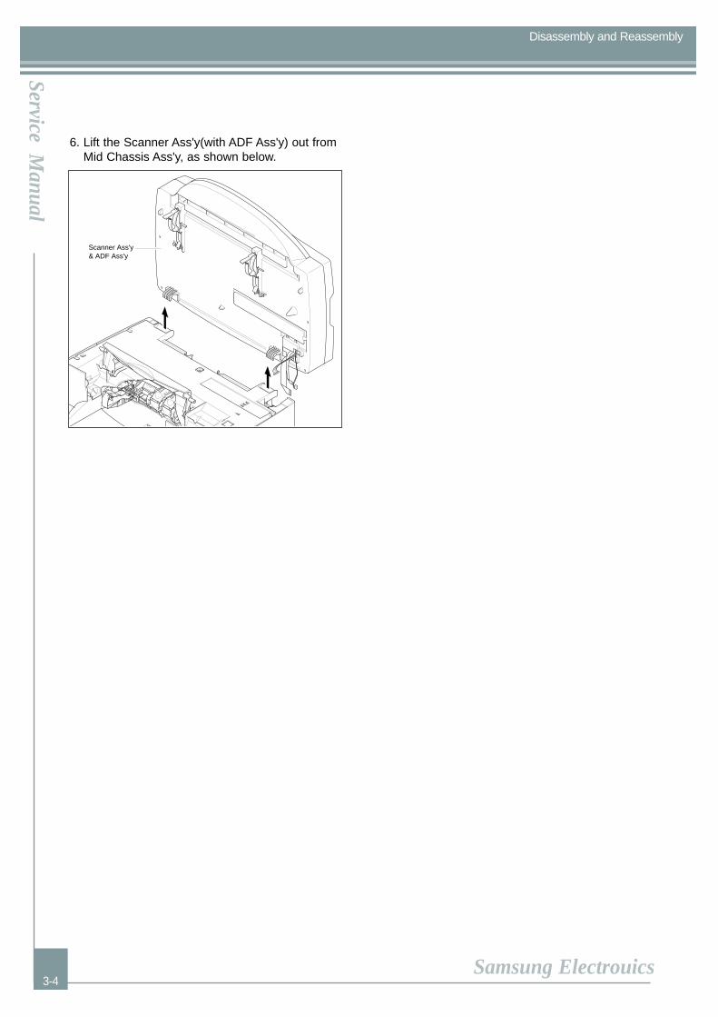
6. Lift the Scanner Ass'y(with ADF Ass'y) out fromMid Chassis Ass'y, as shown below.
Scanner Ass'y & ADF Ass'y
PrecautionsPrecautionsService M
anual
Samsung Electrouics
Disassembly and Reassembly
3-5
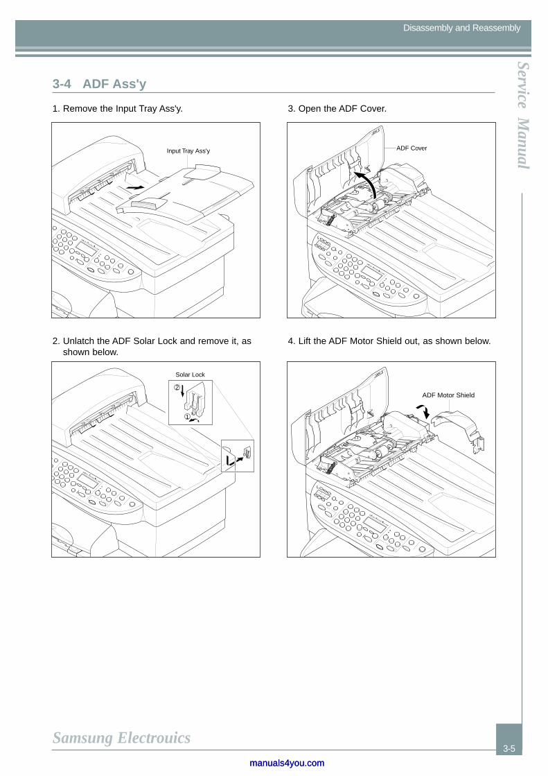
3-4 ADF Ass'y
1. Remove the Input Tray Ass'y.
2. Unlatch the ADF Solar Lock and remove it, asshown below.
3. Open the ADF Cover.
4. Lift the ADF Motor Shield out, as shown below.
Input Tray Ass'y
”„»‰ˆ
Solar Lock
”„»‰ˆ
2
1
ADF Cover
˘‰”‰ˆ
”„»‰ˆ
ADF Motor Shield
˘‰”‰ˆ
”„»‰ˆ
manuals4you.commanuals4you.com
Precautions
3-6
Service Manual
Samsung Electrouics
Disassembly and Reassembly
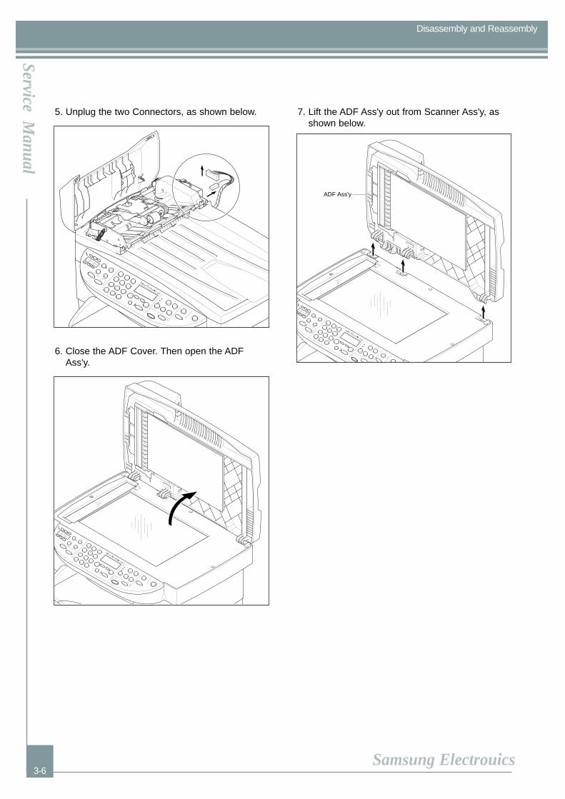
5. Unplug the two Connectors, as shown below.
6. Close the ADF Cover. Then open the ADFAss'y.
7. Lift the ADF Ass'y out from Scanner Ass'y, asshown below.
˘‰”‰ˆ
”„»‰ˆ
˘‰”‰ˆ
”„»‰ˆ
ADF Ass'y
˘‰”‰ˆ
”„»‰ˆ
PrecautionsPrecautionsService M
anual
Samsung Electrouics
Disassembly and Reassembly
3-7
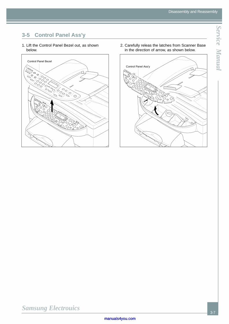
1. Lift the Control Panel Bezel out, as shownbelow.
2. Carefully releas the latches from Scanner Basein the direction of arrow, as shown below.
Control Panel Bezel
˘‰”‰ˆ
”„»‰ˆ
Control Panel Ass'y
3-5 Control Panel Ass'y
manuals4you.commanuals4you.com
Precautions
3-8
Service Manual
Samsung Electrouics
Disassembly and Reassembly
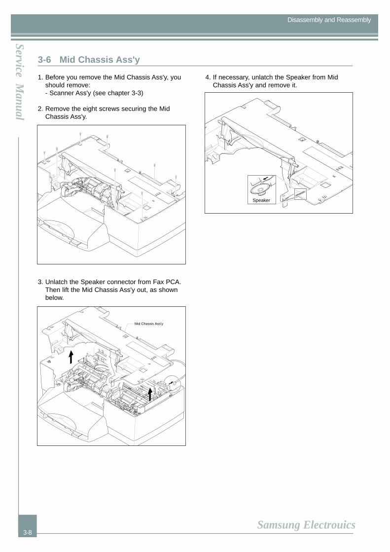
1. Before you remove the Mid Chassis Ass'y, youshould remove:- Scanner Ass'y (see chapter 3-3)
2. Remove the eight screws securing the MidChassis Ass'y.
3. Unlatch the Speaker connector from Fax PCA.Then lift the Mid Chassis Ass'y out, as shownbelow.
4. If necessary, unlatch the Speaker from MidChassis Ass'y and remove it.
3-6 Mid Chassis Ass'y
Speaker
Mid Chassis Ass'y

PrecautionsPrecautionsService M
anual
Samsung Electrouics
Disassembly and Reassembly
3-9
1. Before you remove the Right Side Cover, youshould remove:- Scanner Ass'y (see chapter 3-3)
2. Remove the two screws securing the MidChassis Ass'y, as shown below.
3. Carefully release the Right Side Cover latchesfrom Chassis Ass'y in the direction of arrow, asshown below.
3-7 Right Side Cover
Mid Chassis Ass'y
Side Cover RH
21
1. Before you remove the Left Side Cover, youshould remove:- Scanner Ass'y (see chapter 3-3)
2. Remove the two screws securing the MidChassis Ass'y, as shown below.
3. Carefully release the Left Side Cover latchesfrom Chassis Ass'y in the direction of arrow, asshown below.
3-8 Left Side Cover
Mid Chassis Ass'y
2
1
Side Cover LH
manuals4you.commanuals4you.com

Precautions
3-10
Service Manual
Samsung Electrouics
Disassembly and Reassembly
1. Before you remove the Fax PCA, you shouldremove:- Scanner Ass'y (see chapter 3-3) - Mid Chassis Ass'y (see chapter 3-6) - Right Side Cover (see chapter 3-7)
2. Remove the two screws securing the Fax PCA,as shown below.
3. Carefully release the latches from Main PCA inthe direction of arrow, as shown below.
3-9 Fax PCA
Fax PCA
PrecautionsPrecautionsService M
anual
Samsung Electrouics
Disassembly and Reassembly
3-11
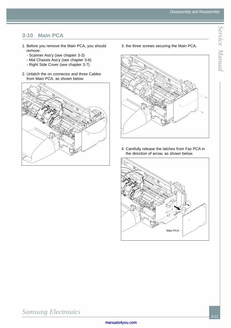
1. Before you remove the Main PCA, you shouldremove:- Scanner Ass'y (see chapter 3-3) - Mid Chassis Ass'y (see chapter 3-6) - Right Side Cover (see chapter 3-7)
2. Unlatch the on connector and three Cablesfrom Main PCA, as shown below.
3. the three screws securing the Main PCA.
4. Carefully release the latches from Fax PCA inthe direction of arrow, as shown below.
3-10 Main PCA
Main PCA
manuals4you.commanuals4you.com

Precautions
3-12
Service Manual
Samsung Electrouics
Disassembly and Reassembly
1. Before you remove the Tray Ass'y, you shouldremove:- Scanner Ass'y (see chapter 3-3) - Mid Chassis Ass'y (see chapter 3-6) - Right Side Cover (see chapter 3-7) - Left Side Cover (see chapter 3-8)
2. Lift up the Output Tray Ass'y in the direction ofarrow, as shown below.
3. Remove the one screw securing the Input TrayAss'y.
4. Push in tab and unlatch the Input Tray Ass'yusing a flat-blade screwdriver, as shown below.
3-11 Tray Ass'y
Output Tray Ass'y
Input Tray Ass'y

PrecautionsPrecautionsService M
anual
Samsung Electrouics
Troubleshooting
4-1
4. Troubleshooting
In this chapter, it was mentioned about the functions for maintaining the product, how to find the causes of the inferior-ity, and troubleshooting method.The service manual is bound the SCX-1350F and SCX-1300 together in one volume.The SCX-1350F has functions such as printer, copy, scanner, and fax. The SCX-1300 has all functions as the SCX-1350F but the fax function.The contents of the manual are standardized for the SCX-1350F. The information about the fax function is not appliedfor the SCX-1300. The differences by each model are explained in a separate way.
The Service Menu is designed for use by trained repair technicians. The following key press definitions will apply:
• [*] and [#] simultaneously then [1] [2] [3] : Provides access to the Service Menu.
• [arrow]: Scrolls through menu functions, advances the cursor
• [enter] : Enter a menu, begins a function, stores a value
• [keypad] : Enters alpha and numerical data
• [cancel] : Stops a test, exits function, exits Service Menu
4.1.1 Service Menu
4.1.1.1 Service Menu User Interface (SCX-1350F)
1. Configuration
enter serial numberenter srvice IDenter model numberset all country parametersset languager/w parameter
2. Special Reports
extended self testparametersfax tracecounter
3. Service Tests
ASF simplex pickASF duplex pickADF simplex ADF duplex pick correct outputADF duplex pick reverse outputcont ADF feedtest scan motortest carriagetest servicetest buttonstest hidden keystest LEDstest LCDtest photo RAM SM CF MStest sensorstest faxtest scan lampDoor snsoradf notch calibration
manuals4you.commanuals4you.com

Precautions
4-2
Service Manual
Samsung Electrouics
Troubleshooting
The Service Menu is designed for use by trained repair technicians. The following key press definitions will apply:
• [<] and [>] simultaneously then [<] [Copy Quality] [>] : Provides access to the Service Menu.
• [arrow] : Scrolls through menu functions, advances the cursor
• [enter] : Enter a menu, begins a function, stores a value
• [cancel] : Stops a test, exits function, exits Service Menu
4.1.1.2 Service Menu User Interface (SCX-1300)
1. Configuration
enter serial numberenter srvice IDenter model numberset all country parametersset languager/w parameter
2. Special Reports
extended self testparametersfax tracecounter
3. Service Tests
ASF simplex pickASF duplex picktest scan motortest carriagetest servicetest buttonstest hidden keystest LEDstest LCDtest photo RAM SM CF MStest sensorstest scan lampDoor snsor
PrecautionsPrecautionsService M
anual
Samsung Electrouics
Troubleshooting
4-3
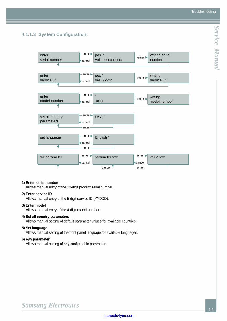
4.1.1.3 System Configuration:
*
enterserial number
pos *val xxxxxxxxxx
writing serialnumber
enterservice ID
pos *val xxxxx
writingservice ID
entermodel number xxxx
set all countryparameters
USA *
set language English *
r/w parameter parameter xxx value xxx
writingmodel number
enterenter
cancel
enterenter
cancel
enter
cancel
enter
cancel
enter
enter
cancel
enter
enter
cancel
enter
cancel
entercancel
enter
1) Enter serial numberAllows manual entry of the 10-digit product serial number.
2) Enter service ID Allows manual entry of the 5-digit service ID (YYDDD).
3) Enter model Allows manual entry of the 4-digit model number.
4) Set all country parametersAllows manual setting of default parameter values for available countries.
5) Set language Allows manual setting of the front panel language for available languages.
6) R/w parameter Allows manual setting of any configurable parameter.
manuals4you.commanuals4you.com
Precautions
4-4
Service Manual
Samsung Electrouics
Troubleshooting
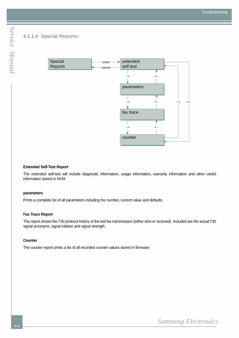
4.1.1.4 Special Reports:
SpecialReports
extendedself test
parameters
fax trace
counter
enter
cancel
-->
-->
-->
<--
<--
<--
--> <--
Extended Self-Test Report
The extended self-test will include diagnostic information, usage information, warranty information and other useful information stored in NVM.
parameters
Prints a complete list of all parameters including the number, current value and defaults.
Fax Trace Report
This report shows the T30 protocol history of the last fax transmission (either sent or received). Included are the actual T30signal acronyms, signal initiator and signal strength.
Counter
The counter report prints a list of all recorded counter values stored in firmware.
PrecautionsPrecautionsService M
anual
Samsung Electrouics
Troubleshooting
4-5
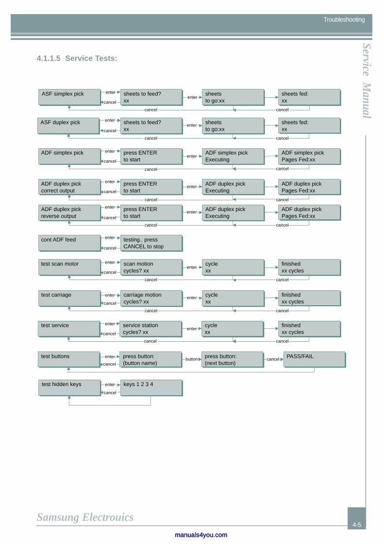
4.1.1.5 Service Tests:
enterenter
cancel
cancel
enterenter
cancel
cancel
enter
cancel
cancel
enter
cancel
cancel
enter
cancel
enter
cancelenter
cancel
enter
cancel
cancel
enter
enter
enter
enter
cancelenter
cancel
buttonenter
cancelcancel
cancel
cancel
cancel
cancel
cancel
cancel
cancel
enter
cancel
enter
cancel
cancel
enter
ASF simplex pick sheets to feed?xx
sheetsto go:xx
ASF duplex pick sheets to feed?xx
sheetsto go:xx
ADF simplex pick press ENTERto start
ADF duplex pickcorrect output
press ENTERto start
cont ADF feed testing.. pressCANCEL to stop
test scan motor scan motioncycles? xx
cyclexx
test carriage carriage motioncycles? xx
ADF simplex pickExecuting
ADF duplex pickExecuting
cyclexx
test service service stationcycles? xx
cyclexx
test buttons press button:(button name)
press button:(next button)
PASS/FAIL
sheets fed:xx
sheets fed:xx
ADF simplex pickPages Fed:xx
ADF duplex pickPages Fed:xx
finishedxx cycles
finishedxx cycles
finishedxx cycles
test hidden keys keys 1 2 3 4
ADF duplex pickreverse output
press ENTERto start
ADF duplex pickExecuting
ADF duplex pickPages Fed:xx
cancel
manuals4you.commanuals4you.com
Precautions
4-6
Service Manual
Samsung Electrouics
Troubleshooting
enter
cancel
enter
cancel
enter
cancel
enter
cancel
enter
cancel
enter
enter
enter
enter
cancel
cancel
cancel
cancel
-->
-->
-->
<--
<--
<--
enter
cancel
1=ON, 0=off2=Rev Video
photo card test1: Basic 2: Extend
PASS/FAIL
sensors DLEPstate 0000
onhook monitor
offhook monitor
eavesdropmonitor
signal power
scan lamp ONCANCEL to end
Door sensorinactive
r=00 00Hz tlp=0
dial tone/no dial tone
f3=0 f2=0 f1=0 0
recv power: XXX
CF SM MS SD P P P P
enter
cancel
test LCD
test photoRAM SAM CF MS
test mediasensor
test sensors
test fax
test scan lamp
Door sensor
adf notchrecalibration
enter
cancel
enter
cancel
performingrecalibration
recalibrationcompleted
enter
cancel

PrecautionsPrecautionsService M
anual
Samsung Electrouics
Troubleshooting
4-7
1) ASF simplex pick Subsystem test of the product ability to pick sheets from the ASF tray.
2) ASF duplex pick Subsystem test of the product duplex media handling. Requires a duplexer.
3) ADF simplex pick Subsystem test of the ADF ability to feed sheets individually.
4) ADF duplex pick Subsystem test of the ADF duplex ability.
5) Cont ADF feed Subsystem test of the ADF motor and drive mechanism.
6) Test scan motor Subsystem test of the flatbed scan motor and scan drive mechanism.
7) Test carriage Subsystem test of the carriage motor, motor control and drive mechanism.
8) Test service Subsystem test of the service station motor and drive mechanism.
9) Test buttons Interactive test of all front panel buttons.
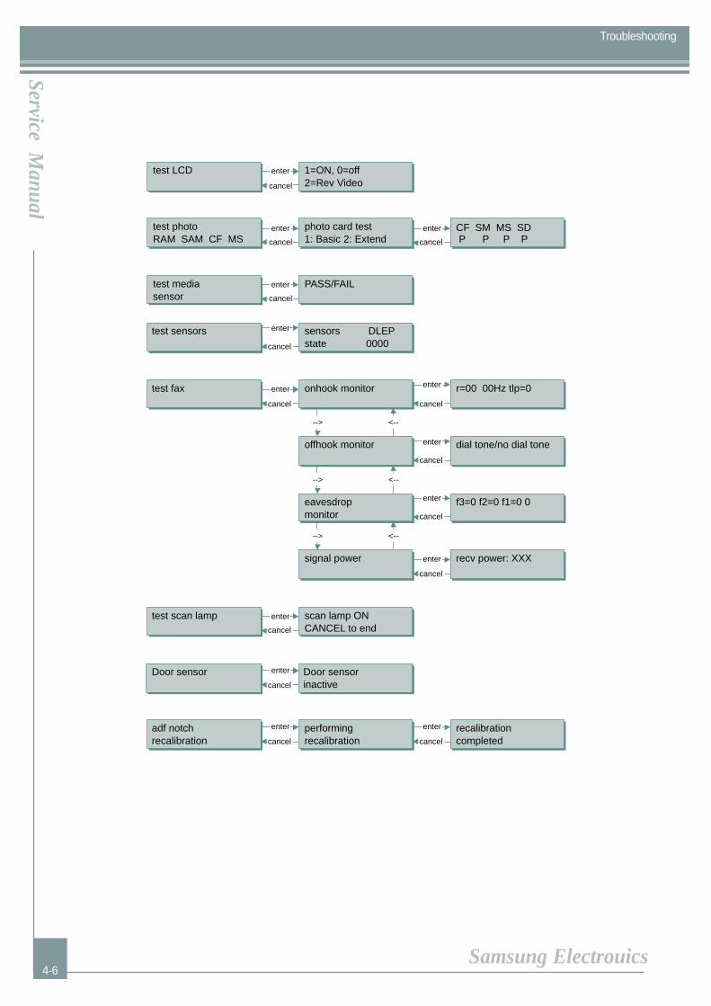
10) Test LEDs Continuous test of LED functionality (blinking and on steady)
11) Test LCD Subsystem functional test of all LCD segments and back light.
12) Test photo Subsystem test of the photo, photo w/memory and memory PCAs.
13) Test media sensor Subsystem functional test of the media sensor.
14) Test sensors Interactive functional test of the door, OOPS, second and ADF optical sensors.
15) Test fax Various monitor test for ring, CNG and dial tone detection and receive power.
16) Test scan lamp Interactive functional test of the scanner lamp.
17) Door sensor Disables the door interlock sensor to allow other tests to run with the door in the open position.
18) adf notch recalibrationPerforms a recalibration of the adf notch.
manuals4you.commanuals4you.com

Precautions
4-8
Service Manual
Samsung Electrouics
Troubleshooting
4.1.2 Information Menu
4.1.2.1 Information Menu user Interface
The Information Menu allows access to key information required for the support of the product without having to print
anything.
The following key press definitions will apply for this product:
• [Menu] [Start Copy Color]: At ready state provides access to the Information Menu
• [arrow]: Scrolls through the information available; [cancel]: Exits the Information Menu
INFORMATION MENU FUNCTION DESCRIPTIONS
1) Info Menu 1) Info MenuAllows access to the Info menu and displays the F/W build
2) Model Number Displays the product model number.
3) Serial NumberDisplays the product serial number.
4) Photo Displays the status of the functionality of the photo card (working or not working)
5) Country/Language Displays the current country and language settings
6) Counters Displays the current page count and power cycles settings
7) Last Error Displays the last know error the product encountered.
2) Model Number
3) Serial Number
4) Photo
5) Country/Language
6) Counters
7) Last Error
PrecautionsPrecautionsService M
anual
Samsung Electrouics
Troubleshooting
4-9
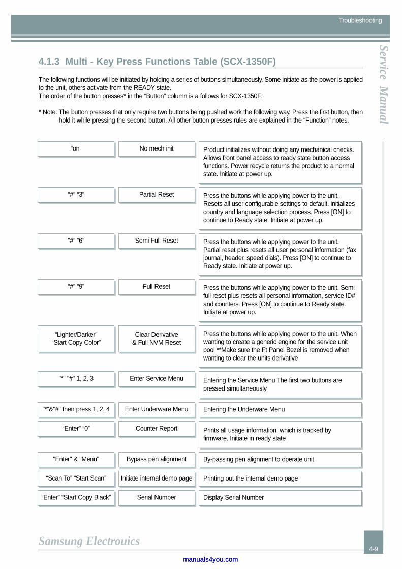
4.1.3 Multi - Key Press Functions Table (SCX-1350F)
The following functions will be initiated by holding a series of buttons simultaneously. Some initiate as the power is appliedto the unit, others activate from the READY state.The order of the button presses* in the “Button” column is a follows for SCX-1350F:
* Note: The button presses that only require two buttons being pushed work the following way. Press the first button, thenhold it while pressing the second button. All other button presses rules are explained in the “Function” notes.
“on” No mech init Product initializes without doing any mechanical checks.Allows front panel access to ready state button accessfunctions. Power recycle returns the product to a normalstate. Initiate at power up.
“#” “3” Partial Reset Press the buttons while applying power to the unit.Resets all user configurable settings to default, initializescountry and language selection process. Press [ON] tocontinue to Ready state. Initiate at power up.
“#” “6” Semi Full Reset Press the buttons while applying power to the unit.Partial reset plus resets all user personal information (faxjournal, header, speed dials). Press [ON] to continue toReady state. Initiate at power up.
“#” “9” Full Reset
"*" "#" 1, 2, 3
"*"&"#" then press 1, 2, 4
Enter Service Menu
Enter Underware Menu
Press the buttons while applying power to the unit. Semifull reset plus resets all personal information, service ID#and counters. Press [ON] to continue to Ready state.Initiate at power up.
“Lighter/Darker” “Start Copy Color”
Clear Derivative & Full NVM Reset
Press the buttons while applying power to the unit. Whenwanting to create a generic engine for the service unitpool **Make sure the Ft Panel Bezel is removed whenwanting to clear the units derivative
Entering the Service Menu The first two buttons arepressed simultaneously
“Enter” “0” Counter Report Prints all usage information, which is tracked byfirmware. Initiate in ready state
Entering the Underware Menu
"Enter" & "Menu" Bypass pen alignment By-passing pen alignment to operate unit
“Scan To” “Start Scan” Initiate internal demo page Printing out the internal demo page
“Enter” “Start Copy Black” Serial Number Display Serial Number
manuals4you.commanuals4you.com
Precautions
4-10
Service Manual
Samsung Electrouics
Troubleshooting
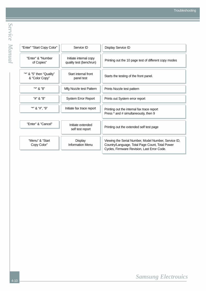
“Enter” “Start Copy Color” Service ID Display Service ID
"*" & "8" Mfg Nozzle test Pattern Prints Nozzle test pattern
"#" & "8" System Error Report
“*” & “#”, “9” Initiate fax trace report
Prints out System error report
"Enter" & "Number of Copies"
Initiate internal copy quality test (benchrun)
Printing out the 10 page test of different copy modes
"*" & "5" then “Quality” & “Color Copy”
Start internal frontpanel test
Starts the testing of the front panel.
Printing out the internal fax trace report Press * and # simultaneously, then 9
"Enter" & "Cancel" Initiate extended self test report
Printing out the extended self test page
“Menu” & “Start Copy Color”
Display Information Menu
Viewing the Serial Number, Model Number, Service ID,Country/Language, Total Page Count, Total PowerCycles, Firmware Revision, Last Error Code.
PrecautionsPrecautionsService M
anual
Samsung Electrouics
Troubleshooting
4-11
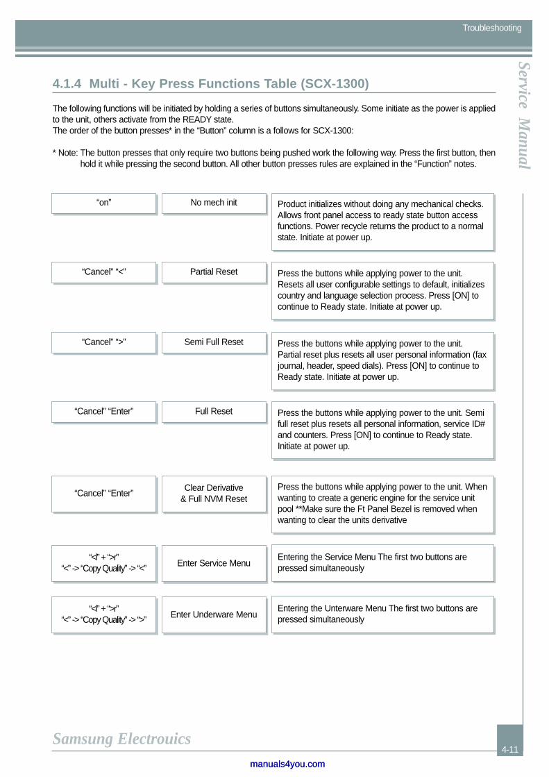
4.1.4 Multi - Key Press Functions Table (SCX-1300)
The following functions will be initiated by holding a series of buttons simultaneously. Some initiate as the power is appliedto the unit, others activate from the READY state.The order of the button presses* in the “Button” column is a follows for SCX-1300:
* Note: The button presses that only require two buttons being pushed work the following way. Press the first button, thenhold it while pressing the second button. All other button presses rules are explained in the “Function” notes.
“on” No mech init Product initializes without doing any mechanical checks.Allows front panel access to ready state button accessfunctions. Power recycle returns the product to a normalstate. Initiate at power up.
“Cancel” “<” Partial Reset Press the buttons while applying power to the unit.Resets all user configurable settings to default, initializescountry and language selection process. Press [ON] tocontinue to Ready state. Initiate at power up.
“Cancel” “>” Semi Full Reset Press the buttons while applying power to the unit.Partial reset plus resets all user personal information (faxjournal, header, speed dials). Press [ON] to continue toReady state. Initiate at power up.
“Cancel” “Enter” Full Reset Press the buttons while applying power to the unit. Semifull reset plus resets all personal information, service ID#and counters. Press [ON] to continue to Ready state.Initiate at power up.
“Cancel” “Enter”
“<l” + “>r”“<” -> “Copy Quality” -> “<”
Clear Derivative & Full NVM Reset
Enter Service Menu
Press the buttons while applying power to the unit. Whenwanting to create a generic engine for the service unitpool **Make sure the Ft Panel Bezel is removed whenwanting to clear the units derivative
Entering the Service Menu The first two buttons arepressed simultaneously
“<l” + “>r”“<” -> “Copy Quality” -> “>” Enter Underware Menu
Entering the Unterware Menu The first two buttons arepressed simultaneously
manuals4you.commanuals4you.com

Precautions
4-12
Service Manual
Samsung Electrouics
Troubleshooting
4.1.5 Service ID (born-on-date)
This product will store the date at which the product was first installed. The date is known as the Service ID# (or born-on-date).The format of the Service ID # should follow that used on past products which is YYDDD. The YY value is added to“1990” to get the current year. The DDD value represent the day. Leap year is not considered.
If the Service ID# is cleared from the unit (full reset) or is not formatted correctly, a new Service ID# will be establishedthe next time the device is contected to the PC and the Software is running. The Service ID# can be manually modifiedby a trained technician using the Service Menu. The Service ID# may be viewed by pressing a front panel key sequenceor via the software (refer to the Seine Software ERS’s).
"Enter" & "Menu" Bypass pen alignment By-passing pen alignment to operate unit
“Scan To” “Start Scan” Initiate internal demo page Printing out the internal demo page
“Enter” “Start Copy Black” Serial Number Display Serial Number
“Enter” “Start Copy Color” Service ID Display Service ID
"Enter" & "Number of Copies"
Initiate internal copy quality test (benchrun)
Printing out the 10 page test of different copy modes
"Enter" & "Cancel" Initiate extended self test report
Printing out the extended self test page
“Menu” & “Start Copy Color”
Display Information Menu
Viewing the Serial Number, Model Number, Service ID,Country/Language, Total Page Count, Total PowerCycles, Firmware Revision, Last Error Code.
PrecautionsPrecautionsService M
anual
Samsung Electrouics
Troubleshooting
4-13
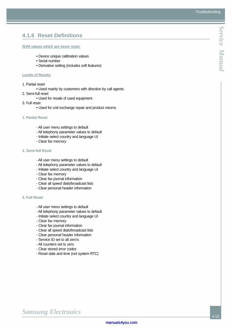
4.1.6 Reset Definitions
NVM values which are never reset:
• Device unique calibration values• Serial number• Derivative setting (includes soft features)
Levels of Resets:
1. Partial reset• Used mainly by customers with direction by call agents.
2. Semi-full reset• Used for resale of used equipment
3. Full reset• Used for unit exchange repair and product returns
1. Partial Reset
- All user menu settings to default- All telephony parameter values to default- Initiate select country and language UI- Clear fax memory
2. Semi-full Reset
- All user menu settings to default- All telephony parameter values to default- Initiate select country and language UI- Clear fax memory- Clear fax journal information- Clear all speed dials/broadcast lists- Clear personal header information
3. Full Reset
- All user menu settings to default- All telephony parameter values to default- Initiate select country and language UI- Clear fax memory- Clear fax journal information- Clear all speed dials/broadcast lists- Clear personal header information- Service ID set to all zero’s- All counters set to zero- Clear stored error codes- Reset date and time (not system RTC)
manuals4you.commanuals4you.com
Precautions
4-14
Service Manual
Samsung Electrouics
Troubleshooting
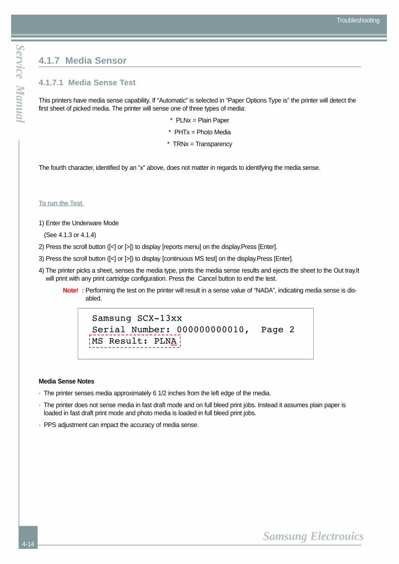
4.1.7 Media Sensor
4.1.7.1 Media Sense Test
This printers have media sense capability. If “Automatic” is selected in “Paper Options Type is” the printer will detect thefirst sheet of picked media. The printer will sense one of three types of media:
* PLNx = Plain Paper
* PHTx = Photo Media
* TRNx = Transparency
The fourth character, identified by an “x” above, does not matter in regards to identifying the media sense.
To run the Test
1) Enter the Underware Mode
(See 4.1.3 or 4.1.4)
2) Press the scroll button ([<] or [>]) to display [reports menu] on the display.Press [Enter].
3) Press the scroll button ([<] or [>]) to display [continuous MS test] on the display.Press [Enter].
4) The printer picks a sheet, senses the media type, prints the media sense results and ejects the sheet to the Out tray.Itwill print with any print cartridge configuration. Press the Cancel button to end the test.
Note! : Performing the test on the printer will result in a sense value of “NADA”, indicating media sense is dis-abled.
Media Sense Notes
· The printer senses media approximately 6 1/2 inches from the left edge of the media.
· The printer does not sense media in fast draft mode and on full bleed print jobs. Instead it assumes plain paper isloaded in fast draft print mode and photo media is loaded in full bleed print jobs.
· PPS adjustment can impact the accuracy of media sense.
PrecautionsPrecautionsService M
anual
Samsung Electrouics
Troubleshooting
4-15
4.1.7.2 Media Sense LTVG Calibration
To run the Test
1) Power on the printer.
2) Insert two sheets of HP Bright White Paper.
3) Enter the Underware Mode
(See 4.1.3 or 4.1.4)
4) Press the scroll button ([<] or [>]) to display [reports menu] on the display.Press [Enter].
5) Press the scroll button ([<] or [>]) to display [Media sense cal] on the display.Press [Enter].
6) The printer picks a sheet, senses the media type.
7) Reenter the Underware Mode
(See 4.1.3 or 4.1.4)
8) Press the scroll button ([<] or [>]) to display [reports menu] on the display.Press [Enter].
9) Press the scroll button ([<] or [>]) to display [techy self test] on the display.Press [Enter]
10)The printer picks a sheet of paper and prints the NVRAM values.
* You can see the test result in the 10th line from prints lower part.
Example) LTVG : (plain) 115, (glossy) 128
Value for plain paper must be 80-180 but not 128 which is the default. The value for glossy media is meaning-less at this point in time.
manuals4you.commanuals4you.com

Samsung Electronics
Service Manual
5-1
5.1 SCX-1300 / XIL
Service Possibility Parts List
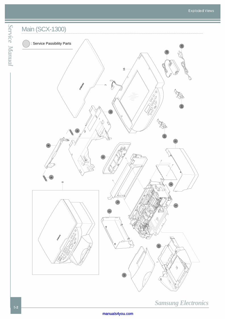
Main-1 AS-ASS’Y PRINT MECH NILE JB81-00423A
Main-2 AS-PANEL LEFT SIDE JB81-00390A
Main-3 AS-PANEL RIGHT SIDE JB81-00391A
Main-4 AS-ASS’Y PCA MAIN FLASH JB81-00398A
Main-5 AS-PANEL REAR JB81-00393A
Main-6 AS-ASS’Y CLEANOUT JB81-00396A
Main-8 AS-DOOR FRONT JB81-00394A
Main-9 AS-SPRING DOOR JB81-00417A
Main-10 AS-CAM SLIDE JB81-00410A
Main-11 AS-COVER ENGINE JB81-00476A
Main-12 AS-ASS’Y PM OUTPUT TRAY JB81-00401A
Main-13 AS-ASS’Y PM INPUT TRAY JB81-00400A
Main-14 ADAPTOR-SEINE JB44-00032A
Main-15 CBF-POWER CORD 3903-000133
Mechanism-1 AS-ASS’Y WINGFRAME LT JB81-00402A
Mechanism-2 AS-ASS’Y WINGFRAME RT JB81-00403A
Mechanism-8 AS-ENCODER STRIP JB81-00373A
Mechanism-10 AS-ASS’Y GROUND PLATE JB81-00399A
Scanner-2 AS-SCANNER MODULE CABLE JB81-00418A
Scanner-3 CCD MODULE JB81-00474A
Scanner-4 AS-ASS’Y CONTROL PANEL JB81-00389A
Scanner-5 AS-WINDOW LCD JB81-00408A
Scanner-6 AS-CONTROL PANEL BEZEL JB81-00432A
Scanner-7 AS-SCANNER GLASS JB81-00407A
Scanner-9 AS-ADF WINDOW COVER JB81-00388A
Scanner-10 AS-PANEL WHITE BACKGROU JB81-00415A
Scanner-12 SCAN BASE ASSY JB81-00475A
Samsung Electronics
Service Manual
5-2
Main (SCX-1300)
”„»
‰̂
0
3
4
5
11
8
9
10
9
10
16
7
˘‰”‰̂
”„»
‰̂
13
12
1
2
14
15
6
: Service Passibility Parts
manuals4you.commanuals4you.com

Samsung Electronics
Service Manual
5-3
Mechanism (SCX-1300)
0
1
2
10
3
3-1
5
67
8
9
4
: Service Passibility Parts

Samsung Electronics
Service Manual
5-4
Scanner (SCX-1300)
7
8
9
10
12
11
1
2
3
4
6
5
: Service Passibility Parts
manuals4you.commanuals4you.com

Samsung Electronics
Service Manual
5-5
5.1 SCX-1350F
Service Possibility Parts List
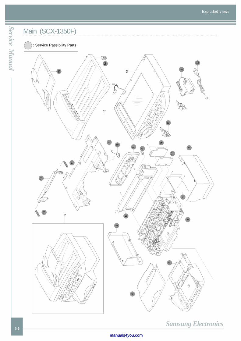
Main-1 AS-ASSY PRINT MECH SEIN JB81-00422A
Main-2 AS-PANEL LEFT SIDE JB81-00390A
Main-3 AS-PANEL RIGHT SIDE JB81-00391A
Main-4 AS-ASSY PCA MAIN FLASH JB81-00397A
Main-5 AS-FAX PCA JB81-00419A
Main-6 AS-PANEL REAR JB81-00393A
Main-7 AS-ASSY CLEANOUT JB81-00396A
Main-8 AS-PLUG_RJ11 JB81-00406A
Main-9 COVER ENGINE JB81-00476A
Main-10 AS-DOOR FRONT JB81-00394A
Main-11 AS-SPRING DOOR JB81-00417A
Main-12 AS-CAM SLIDE JB81-00410A
Main-14 AS-SOLAR LOCK ADF JB81-00411A
Main-16 AS-ASSY INPUT TRAY JB81-00395A
Main-17 AS-ASSY PM OUTPUT TRAY JB81-00401A
Main-18 AS-ASSY PM INPUT TRAY JB81-00400A
Main-19 AS-SPEAKER ASSY JB81-00425A
Main-20 AS-FAX INSULATOR JB81-00424A
Main-21 CBF-POWER CORD 3903-000133
Main-22 ADAPTOR-SEINE JB44-00032A
Mechanism-1 AS-ASSY WINGFRAME LT JB81-00402A
Mechanism-2 AS-ASSY WINGFRAME RT JB81-00403A
Mechanism-8 AS-ENCODER STRIP JB81-00373A
Mechanism-10 AS-ASSY GROUND PLATE JB81-00399A
Scanner-2 AS-SCANNER MODULE CABLE JB81-00418A
Scanner-3 CCD MODULE JB81-00474A
Scanner-4 AS-ASSY CONTROL PANEL JB81-00413A
Scanner-5 AS-WINDOW LCD JB81-00408A
Scanner-6 AS-CONTROL PANEL BEZEL JB81-00430A SCX-1350F/XIL
Scanner-9 AS-SCANNER GLASS JB81-00407A
Scanner-11 AS-ADF WINDOW GLASS JB81-00404A
Scanner-12 AS-ADF WINDOW FRAME JB81-00412A
Scanner-13 AS-ADF ASSEMBLY JB81-00428A
Scanner-14 AS-FOAM PAD ASSY JB81-00414A
Scanner-15 AS-ADF BASE ASSY JB81-00416A
Scanner-16 AS-AY BOGIE JB81-00420A
Scanner-17 AS-ADF MOTOR SHIELD JB81-00409A
Scanner-18 AS-ADF SEPARATOR PAD JB81-00421A
Scanner-20 AS-FLAG_INPUT TRAY JB81-00405A
Scanner-21 AS-COVER ADF JB81-00392A
Scanner-22 AS-ADF FLAG SPRING JB81-00427A
Scanner-23 SCAN BASE ASSY JB81-00475A
Samsung Electronics
Service Manual
5-6
Main (SCX-1350F)
0
9
10
11
11
12
13
1415
16
19
18
17
1
2
3
21
22
4
5
20
6
7 8
: Service Passibility Parts
manuals4you.commanuals4you.com

Samsung Electronics
Service Manual
5-7
Mechanism (SCX-1350F)
0
1
2
10
3
3-1
5
67
8
9
4
: Service Passibility Parts

Samsung Electronics
Service Manual
5-8
Scanner (SCX-1350F)
1
2
34
5
6
7
89
10
1112
14
15
16
17
18
22
19
20
21
13
23
: Service Passibility Parts
manuals4you.commanuals4you.com

PrecautionsPrecautionsService M
anual
Samsung Electrouics
Block Diagram
6-1
6. Block Diagram
Car
riage
Mot
orP
aper
Fee
d M
otor
+31
V+
31V
+31
V+
3.3V
Ser
vice
Sta
tion
Mot
or
Hea
d D
river
Ink
Pen
M90
(P90
)
Ink
Pen
C90
+1.
8V+
3.3V
+32
V
<Car
riag
e P
CA
>
U17
5E
EP
RO
M 6
4kbe
t
U29
An
alo
g A
sic
- V
okta
ge R
egul
ator
- M
otor
Driv
er-
Pap
er E
ncod
er
+3.
3V
+3.
3V
+3.
3V, +
5V
+3.
3V, +
5V
+1.
8V
+31
V
+3.
3V
+1.
8V
Tim
er K
eepe
rU
39S
RA
M
US
B C
onne
ctor
LIU
X-T
al 1
6MH
z
Doo
r S
enso
r
<O
PP
S S
enso
r>
Pap
er E
ncod
er
U19
Fla
sh M
emor
y+
5V
+3.
3V
LCD
LED
Key
s(F
AX
Key
=13
50F
Onl
y)<
OP
E P
anel
>
+3.
3V
U22
64M
bit S
DR
AM
+3.
3V
+3.
3V
CC
D
<Mai
n P
CA
>
Sca
n M
otor
U14
DR
V_A
sic
+3.
3V
U74
DR
V_A
sic
AD
F M
otor
(SC
X-1
350F
Onl
y)
U36
CP
U
US
B D
river
Pen
Driv
erI/O
Ad
apto
r
Inpu
t : 1
00 -
240
V 5
0/60
Hz
Out
put :
+31
V 1
450m
A
G
nd
Related Documents