R/V Hugh R. Sharp Reson 7125 SVP2 Multibeam Echosounder System Calibration March 21-23, 2016 Report prepared by: Kevin Jerram Center for Coastal and Ocean Mapping / Joint Hydrographic Center University of New Hampshire Durham, New Hampshire Vicki Ferrini Lamont-Doherty Earth Observatory Columbia University Palisades, New York This work is supported by the National Science Foundation under Grant No. OCE-1524585

Welcome message from author
This document is posted to help you gain knowledge. Please leave a comment to let me know what you think about it! Share it to your friends and learn new things together.
Transcript
R/V Hugh R. Sharp Reson 7125 SVP2 Multibeam Echosounder System Calibration March 21-23, 2016
Report prepared by:
Kevin Jerram
Center for Coastal and Ocean Mapping / Joint Hydrographic Center
University of New Hampshire
Durham, New Hampshire
Vicki Ferrini
Lamont-Doherty Earth Observatory
Columbia University
Palisades, New York
This work is supported by the National Science Foundation under Grant No. OCE-1524585
2
Table of Contents Survey System Components ................................................................................................................................................... 3
Overview of System Geometry ............................................................................................................................................... 3
Geometric Calibration ............................................................................................................................................................. 5
Principal Findings & Recommendations ................................................................................................................................. 9
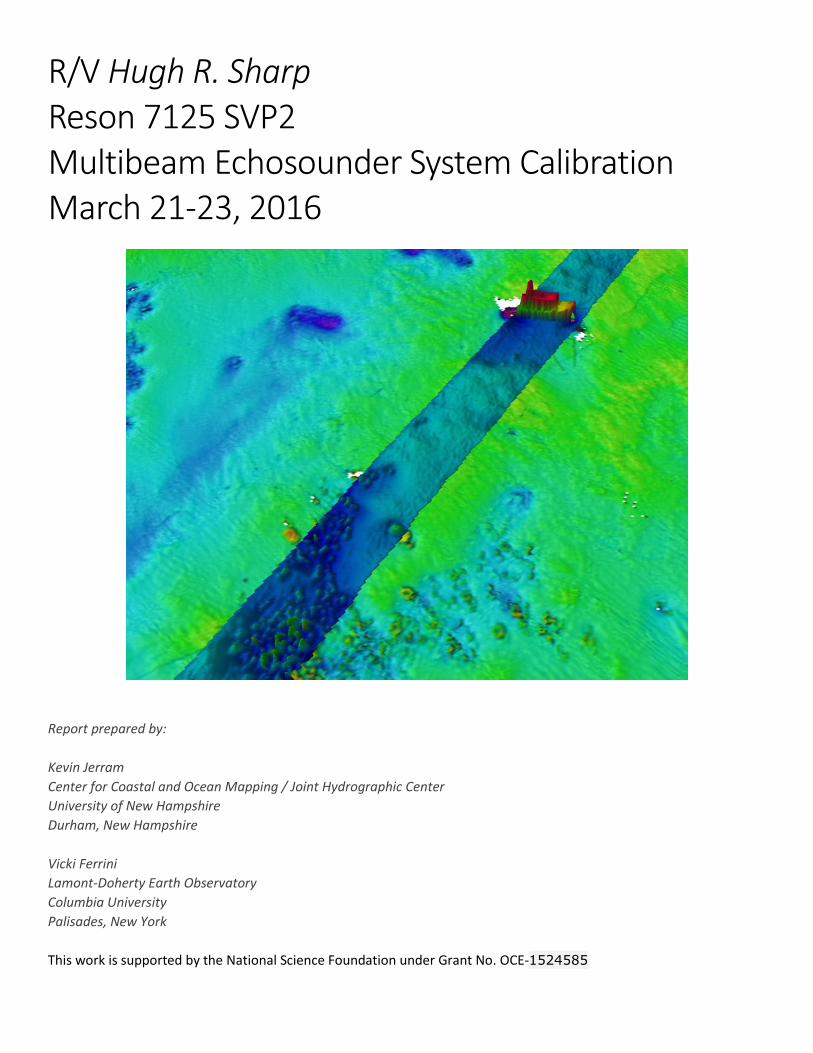
Cover image: A shipwreck and tire dumping ground at the Redbird Reef site observed with the Reson 7125 aboard the
R/V Hugh R. Sharp during HRS1602 overlain on background bathymetry collected by the NOAA Ship Ferdinand R.
Hassler. Vertical scales of the Sharp and Hassler data are 3X and 0X, respectively, with various depth color scales.
3
Introduction
The R/V Hugh R. Sharp is equipped with a Reson 7125 SVP2 (200/400 kHz) multibeam echosounder installed on a drop
keel and an Applanix POS-MV 320 positioning and attitude system. Traditionally, survey planning and data acquisition
are handled using Hypack HYSWEEP software installed on the RESON acquisition machine. These systems were
reviewed by personnel from the Multibeam Advisory Committee (MAC), University of Delaware (UDEL), and Reson
during sea acceptance trials in October 2012 with satisfactory results and have been used for very high quality mapping
exercises (e.g., evaluation of bedform migration at the ‘Redbird Reef’ artificial reef site before and after major storms).
Given the seasonal removal/reinstallation of the Reson 7125, frequent drop keel adjustment (e.g., retracted dockside
and extended at sea), and personnel changes since sea trials in 2012, the MAC was asked to review the most recent
Reson 7125 installation and perform a patch test prior to the summer 2016 operational season. Preliminary review of
the system configuration and functionality testing were performed dockside on March 21 and a patch test was
performed during a public day cruise (HRS1602) on March 22 at the ‘Redbird Reef’ artificial reef site. This site was much
shallower (20-30 m) than ideal depths for calibration of angular offsets, but included many submerged targets making
distinct features for latency, pitch, and yaw calibration, plus ample ‘flat’ seafloor for roll calibration. This document
describes the system geometry review, patch test procedure and results, and recommendations for operation.
In addition to remote support provided by Val Schmidt (UNH), Glen Rice (NOAA), Vitad Pradith (Hypack), and Paul
Johnson (UNH), on-board participants in multibeam operation during HRS1602 included:
1. Timothy Deering (UDEL)
2. Jon Swallow (UDEL)
3. KG Fairbarn (UDEL)
4. Art Trembanis (UDEL)
5. Vicki Ferrini (LDEO)
6. Kevin Jerram (UNH)
Survey System Components The mapping system consists of the following components:
1. Reson 7125 SVP2/FP3 multibeam echosounder (200/400 kHz) with surface velocimeter
2. Applanix POS-MV V5 inertial motion sensor: s/n 5250
3. Seabird 911 conductivity-temperature-depth (CTD) sensor
4. Hypack 2016 data acquisition software
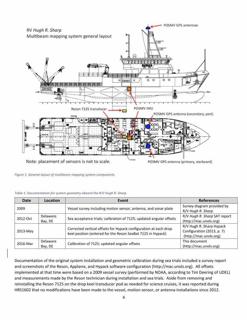
Overview of System Geometry In this report, we use the term ‘system geometry’ to mean the reference frame(s) of the vessel and the linear and
angular offsets of the primary components of the multibeam mapping systems, including the TX array, RX array, and
motion sensor. These parameters are critical for data collection in an unbiased and repeatable manner. Figure 1
provides an overview of the sensor layout and Table 1 provides an outline of available documentation describing the
system geometry.
4
Figure 1. General layout of multibeam mapping system components.
Table 1. Documentation for system geometry aboard the R/V Hugh R. Sharp.
Documentation of the original system installation and geometric calibration during sea trials included a survey report
and screenshots of the Reson, Applanix, and Hypack software configuration (http://mac.unols.org). All offsets
implemented at that time were based on a 2009 vessel survey (performed by NOAA, according to Tim Deering of UDEL)
and measurements made by the Reson technician during installation and sea trials. Aside from removing and
reinstalling the Reson 7125 on the drop keel transducer pod as needed for science cruises, it was reported during
HRS1602 that no modifications have been made to the vessel, motion sensor, or antenna installations since 2012.
Date Location Event References
2009 Vessel survey including motion sensor, antenna, and sonar plate Survey diagram provided by R/V Hugh R. Sharp
2012-Oct Delaware Bay, DE
Sea acceptance trials; calibration of 7125; updated angular offsets R/V Hugh R. Sharp SAT report (http://mac.unols.org)
2013-May Corrected vertical offsets for Hypack configuration at each drop keel position (entered for the Reson SeaBat 7125 in Hypack)
R/V Hugh R. Sharp Hypack Configuration (2013, p. 7) (http://mac.unols.org)
2016-Mar Delaware Bay, DE
Calibration of 7125; updated angular offsets This document (http://mac.unols.org)
5
The vertical position of the transducer pod depends directly on the drop keel position used during survey, and this value
is reflected in the transducer vertical offset applied in Hypack during acquisition. It was discovered after the 2012 sea
trials that the drop keel control bolts designed to provide flush, 1-m, and 2-m extension of the transducer pod were
machined with 1-yard spacing. Updated vertical offsets for the transducer in the Hypack frame (with respect to
waterline, not IMU) were provided in May 2013 (http://mac.unols.org). In the absence of more recent vessel surveys or
further corrections, the vertical offsets for each drop keel position provided in 2013 were applied during HRS1602 and
shall continue to be used for data collection moving forward.
Horizontal control of the transducer drop keel is accomplished with an airbag system that ‘pins’ the drop keel within the
vessel frame. Though this has not been investigated directly, this airbag system likely secures the drop keel within
acceptable tolerances for horizontal positioning uncertainty. Furthermore, the horizontal offsets are assumed to be
constant in the ship reference frame for all drop keel positions (i.e., the drop keel moves purely in the vertical direction
in the vessel reference frame). Dockside review of the available documentation confirmed correct translation of the
sensor linear offsets into the Reson, POS-MV, and Hypack configurations using a vessel reference frame centered at the
IMU. The only exception to this convention is that Hypack uses a waterline reference for vertical offsets; the 2013
updated Hypack configuration relative to waterline was maintained for HRS1602.
It is important to note that all angular offsets in multibeam mapping system are attributed exclusively to the transducer
installation in the vessel reference frame. Several factors lead to this approach, which is different from most vessels
visited by the MAC. First, the motion sensor has not been surveyed for its angular offsets in the vessel reference frame;
these values for IMU pitch, roll, and yaw are thus treated as zero in absence of other information. Second, the high-
frequency Reson 7125 transducers are small compared to the much larger, lower-frequency arrays installed in the hull of
other UNOLS vessels. Whereas larger arrays aboard other vessels are installed separately and require individual
measurements of linear and angular offsets for proper configuration, the Reson 7125 RX and TX transducers are installed
on a high-precision factory bracket with known local offsets. It is thus assumed that both 7125 transducers share
identical angular offsets in the vessel reference frame. Third, the removal and reinstallation of the transducers on the
drop keel is likely the dominant source of angular offset variability in the mapping system.
Geometric Calibration After review and confirmation of all linear offsets, the 7125 was calibrated for angular offsets using the 200-kHz transmit mode and a drop keel position of 3’ below the hull. A sound speed profile was calculated from a CTD profile collected immediately prior to calibration, showing a well-mixed water column and nearly constant sound speed of 1478 m/s. As recommended by ship personnel familiar with the survey site, tide data from Atlantic City, NJ, was applied with zero time offset and a scaling factor of 0.9. To achieve high ping rate and sounding density, the ship was operated at 6 kts for all calibration lines (except latency) and the total swath widths were adjusted as follows: Latency: 30°
Pitch: 30° Roll: 140° Yaw: 110°
Calibration tools in QPS Qimera were used by Jerram and Ferrini to evaluate each set of calibration lines, verify no observable positioning latency in the data available, and determine angular offsets for the Reson 7125. Figures 3-5 provide examples of the sounding subsets used for calibration, and Tables 2-3 provide summaries of the post-HRS1602 mapping system offsets in the vessel and Hypack frames. These results are based on the available vessel survey documentation and calibration results; accordingly, these values are to be applied until sensors are modified or another calibration becomes necessary, such as after removal and reinstallation of the transducers.
6
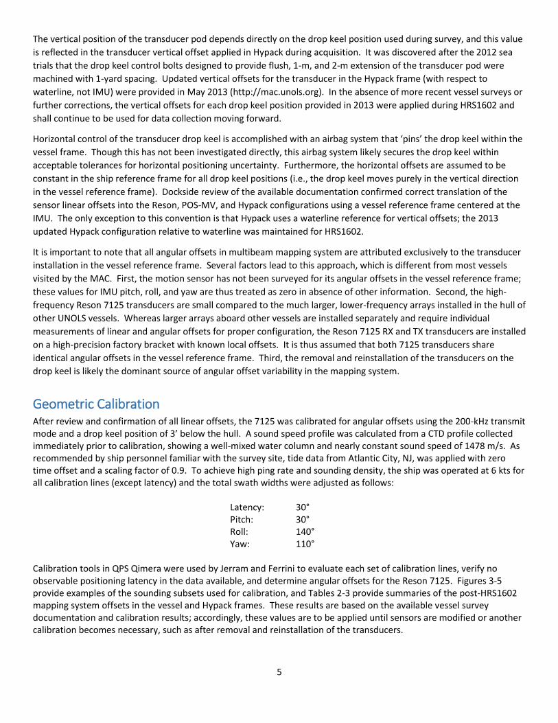
Table 2. Sensor offsets after system geometry review and calibration during HRS1602; only the 7125 angular offsets were modified, with all other linear offsets maintained from the 2013 updated configuration provided by the MAC. Note that the values in this table represent the documented physical layout of sensors using a vessel reference frame centered at the IMU and a given sign convention. The spacing between acoustic centers of the TX and RX arrays at each frequency is given by the Reson schematic copied in Figure 2, showing that the RX array acoustic center is forward of the TX array acoustic center by 0.20 m at 200 kHz and 0.18 m at 400 kHz. At both frequencies, the RX array acoustic center is 0.024 m below the TX array acoustic center. These values are included here for complete description of the physical sensor layout. The sensor and data collection software configurations tend to require only the sonar reference point (TX acoustic center) and use reference frames and/or sign conventions different from those in this table. Table 3 provides the Hypack configuration, and screenshots of all configurations are available in the Appendix.
Drop Keel Sensors in VESSEL frame
Origin at IMU
Alongship Athwartship Vertical Pitch Roll Yaw
BOW + STBD + UP + BOW UP + PORT UP + COMPASS +
-1’ Recessed inside hull
7125 TX -1.767 -0.125 -3.289
0.60 1.04 1.00 7125 RX (200 kHz) -1.567 -0.125 -3.313
7125 RX (400 kHz) -1.587 -0.125 -3.313
0’ Flush with hull
7125 TX -1.767 -0.125 -3.594
0.60 1.04 1.00 7125 RX (200 kHz) -1.567 -0.125 -3.618
7125 RX (400 kHz) -1.587 -0.125 -3.618
3’ Extended below hull
7125 TX -1.767 -0.125 -4.508
0.60 1.04 1.00 7125 RX (200 kHz) -1.567 -0.125 -4.532
7125 RX (400 kHz) -1.587 -0.125 -4.532
6’ Extended below hull
7125 TX -1.767 -0.125 -5.423
0.60 1.04 1.00 7125 RX (200 kHz) -1.567 -0.125 -5.447
7125 RX (400 kHz) -1.587 -0.125 -5.447
POS-MV IMU 0.00 0.00 0.00 0.00 0.00 0.00
POS-MV GPS Antenna – Primary – STBD 4.947 1.940 15.792 - - -
POS-MV GPS Antenna – Secondary - PORT 4.980 -1.804 15.795 - - -
Waterline - - -0.48 - - -
Table 3. Hypack configuration of sensor offsets after system geometry review and calibration during HRS1602. These values reflect the offsets in Table 2 translated into the Hypack reference frame, which takes its vertical reference from waterline and treats downward as positive. Because no new waterline measurement was made during HRS1602, the previous waterline value of 0.48 m below the IMU was maintained. New waterline measurements should be made to update the waterline value in Table 2 and the Hypack vertical reference. For example, if a new waterline measurement of 0.50 m is recorded (e.g., using clear plastic tubing from a through-hull valve near the IMU, as documented in 2012), the difference of 0.02 m (0.50 m new height of IMU above waterline minus the 0.48 m original measurement) should be subtracted from the existing vertical measurements in Hypack. Thus, the IMU height in Hypack would become -0.048 m – 0.02 m = -0.50 m for all drop keel positions. In this hypothetical example, the 7125 vertical offsets for the 3’ drop keel positions would become 4.028 m – 0.02 m = 4.008 m, and so on for the other drop keel positions. This table should be updated whenever new waterline measurements are available. Under the existing data collection setup, the angular offsets should be entered for the Reson transducer in the Hypack configuration prior to data acquisition. Alternatively, data recorded using the Reson software directly (without Hypack) can be adjusted using these angular offsets in post-processing. It was observed that Hypack HSX files correctly preserved the angular offset configuration for post-processing, whereas HSX.s7k files logged in Hypack and native s7k files logged in the Reson software did not.
Drop Keel Sensors in HYPACK frame
Origin at IMU
Alongship Athwartship Vertical Pitch Roll Yaw
BOW + STBD + DOWN + BOW UP + PORT UP + COMPASS +
-1’ Recessed inside hull
7125 Reference Point -1.767 -0.125 2.809 0.60 1.04 1.00
IMU 0.00 0.00 -0.48 0.00 0.00 0.00
0’ Flush with hull
7125 Reference Point -1.767 -0.125 3.114 0.60 1.04 1.00
IMU 0.00 0.00 -0.48 0.00 0.00 0.00
3’ Extended below hull
7125 Reference Point -1.767 -0.125 4.028 0.60 1.04 1.00
IMU 0.00 0.00 -0.48 0.00 0.00 0.00
6’ Extended below hull
7125 Reference Point -1.767 -0.125 4.943 0.60 1.04 1.00
IMU 0.00 0.00 -0.48 0.00 0.00 0.00
7
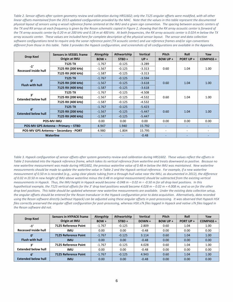
Figure 2. Schematic of a Reson 7125 SVP2 viewed from starboard (Reson SeaBat 7125 Operator Manual, v. 3, p. 179). The acoustic center of the TX array is taken as the sonar reference point, and frequency-specific offsets for the receiver are handled by specifying the SVP2 bracket in configuration. Data processed in Caris should use a vessel configuration file treating the sonar reference point as the Transducer 1 location. In QPS Qimera software testing, the HSX files logged with Hypack successfully preserved the array offsets to populate the Qimera vessel configuration.
Calibration Subsets for Reson 7125 with POS-MV
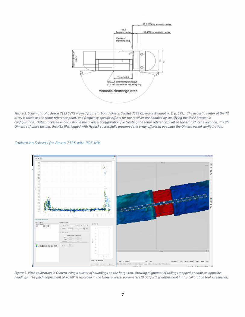
Figure 3. Pitch calibration in Qimera using a subset of soundings on the barge top, showing alignment of railings mapped at nadir on opposite headings. The pitch adjustment of +0.60° is recorded in the Qimera vessel parameters (0.00° further adjustment in this calibration tool screenshot).
8
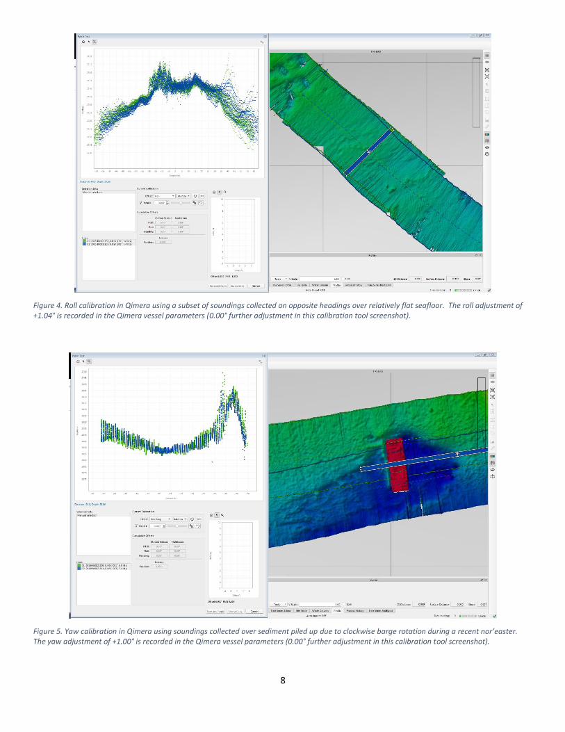
Figure 4. Roll calibration in Qimera using a subset of soundings collected on opposite headings over relatively flat seafloor. The roll adjustment of +1.04° is recorded in the Qimera vessel parameters (0.00° further adjustment in this calibration tool screenshot).
Figure 5. Yaw calibration in Qimera using soundings collected over sediment piled up due to clockwise barge rotation during a recent nor’easter. The yaw adjustment of +1.00° is recorded in the Qimera vessel parameters (0.00° further adjustment in this calibration tool screenshot).
9
Principal Findings & Recommendations The Reson 7125 was successfully calibrated using the POS-MV motion sensor and existing software
configurations. The depths and features available for patch testing limited the angular resolution achievable for
the calibration results, in that small angular differences are not exaggerated by depth. Regardless, the angular
offsets determined during HRS1602 closely match previous results and differed appreciably for only the roll
offset. All results are well within normal patch test ranges and were attributed entirely to the transducer
installation within the vessel reference frame. A patch test must be performed after each removal and
reinstallation of the 7125 or if any sensors are modified.
The POS-MV IMU is rigidly mounted in an engineering space with ample cooling. Based on experience aboard
other vessels, it is strongly recommended that the IMU and its cable be properly labeled with warning messages
to avoid inadvertent human contact or impact. A rigid wire mesh ‘cage’ is common aboard other vessels and
would provide extra protection from accidental stresses on the IMU, its cable, or its mount, all of which would
detrimentally affect multibeam performance and lead to delays for additional patch testing.
The next vessel survey performed should resolve the IMU angular offsets, after which these values can be
entered in the Applanix configuration and a new patch test can be performed. Updated IMU-specific angular
offset could potentially reduce the effect of coupling of the individual angular offsets between the IMU and
transducer installation. This is not a critical issue for the mapping system, but should be addressed with a full
vessel survey (treating the IMU as the origin) during the next major dry-dock period or midlife refit.
The drop keel bolt spacing is in whole yards, not meters. All vertical offset documentation in units of ‘meters’
should be double-checked to ensure that the numerical values correspond to spacing of 1 yd rather than 1 m.
Screenshots of post-HRS1602 Reson, Hypack, and Applanix configurations are included separately. Please
contact the MAC if any discrepancies are found or modifications are made to the configurations which can be
documented with additional screenshots.
It was noted during HRS1602 post-processing that Hypack HSX files opened in Qimera had correctly preserved
the angular offsets entered under the HYSWEEP Survey parameters for the SeaBat 7125 installation, whereas
Hypack HSX.s7k files were much larger and did not properly preserve the offsets. Thus, post-processing HSX files
in Qimera should not require any further adjustment of offsets assuming these (especially vertical for each drop
keel position) are properly entered in HYSWEEP Survey parameters prior to data collection. Other processing
paths may require careful application of the offsets (again, especially vertical for each drop keel position) in
vessel parameters. A set of Caris vessel files with offsets for each frequency and drop keel depth are under
development.
UDEL personnel are presently configuring a new computer with massive storage capability for water column
logging with the Reson 7125. While the existing configuration with Hypack running on the Reson machine
proved stable during HRS1602, the stability of this arrangement has been discussed as a complication during
previous mapping cruises. The MAC recommends moving the Hypack installation to the new water column
logging machine, as this practice of separating the multibeam and logging/planning software is common aboard
other vessels to help improve stability of Hypack operation and minimize data loss when crashes occur. A sheet
of recommendations for water column configuration was provided by V. Pradith of Hypack, available at
ftp://ftp.hypack.com/Documents/SoundingBetterArchives/2014/wcHysweep%20Beta.pdf. The MAC is available
to help in any way it can with setup of this water column logging capability.
The Sharp is the only UNOLS vessel visited by the MAC which using a non-Kongsberg multibeam echosounder;
thus, the tools developed by the MAC to evaluate system noise, swath coverage, and accuracy achieved by other
installations are not readily applied to the data collected aboard the Sharp.

10
Even with the drop keel at 3’ below the hull, bubble sweep plagued the multibeam data when heading into a
swell during HRS1602. Increased acoustic attenuation and noise due to bubble sweep is an extremely common
issue on flush-mounted multibeam installations but is typically remedied with such drop keels and transducer
gondola designs by extending the acoustic sensing faces beyond the mixed bubbly layer. Any upcoming mid-life
vessel refit projects should strongly consider hull modifications to reduce aeration at the bow and improve
bubble diversion away from centerline of the hull.
As a whole, the multibeam system is in satisfactory working condition despite the bubble sweep issue and we do
not anticipate any obvious issues for the 2016 mapping season. All documentation of system offsets and angles
should be maintained and updated carefully as sensor configurations change, in tandem with documentation for
future patch tests. Additional calibration lines in deeper water, collected on an opportunistic basis, can be
forwarded to the MAC for verification of the angular offsets documented in this report.
Related Documents