RTN XMC ODU V100 Hardware Description Issue 07 Date 2011–01–20 HUAWEI TECHNOLOGIES CO., LTD.

Welcome message from author
This document is posted to help you gain knowledge. Please leave a comment to let me know what you think about it! Share it to your friends and learn new things together.
Transcript
RTN XMC ODUV100
Hardware Description
Issue 07
Date 2011–01–20
HUAWEI TECHNOLOGIES CO., LTD.

Copyright © Huawei Technologies Co., Ltd. 2011. All rights reserved.No part of this document may be reproduced or transmitted in any form or by any means without prior writtenconsent of Huawei Technologies Co., Ltd. Trademarks and Permissions
and other Huawei trademarks are trademarks of Huawei Technologies Co., Ltd.All other trademarks and trade names mentioned in this document are the property of their respective holders. NoticeThe purchased products, services and features are stipulated by the contract made between Huawei and thecustomer. All or part of the products, services and features described in this document may not be within thepurchase scope or the usage scope. Unless otherwise specified in the contract, all statements, information,and recommendations in this document are provided "AS IS" without warranties, guarantees or representationsof any kind, either express or implied.
The information in this document is subject to change without notice. Every effort has been made in thepreparation of this document to ensure accuracy of the contents, but all statements, information, andrecommendations in this document do not constitute the warranty of any kind, express or implied.
Huawei Technologies Co., Ltd.Address: Huawei Industrial Base
Bantian, LonggangShenzhen 518129People's Republic of China
Website: http://www.huawei.com
Email: [email protected]
Issue 07 (2011–01–20) Huawei Proprietary and ConfidentialCopyright © Huawei Technologies Co., Ltd.
i

About This Document
OverviewThis document describes the RTN XMC ODU and related devices, which consist of the hybridcoupler, separate mounting components, antenna, antenna adapter, and cables.
Product VersionThe following table lists the product version related to this document.
Product Name Product Version
RTN XMC ODU V100
Intended AudienceThis document is intended for:
l Field engineers
Change HistoryThis provides the changes of the RTN XMC ODU Hardware Description.
l Changes in Issue 07 (20110-01-20)This is the seventh commercial release.The information about the 26 GHz and 38 GHz frequency band of the ODU is added.
l Changes in Issue 06 (2010-11-09)This is the sixth commercial release.The information about the 7 GHz and 23 GHz frequency band of the ODU is updated.
l Changes in Issue 05 (2010-10-22)This is the fifth commercial release.
RTN XMC ODUHardware Description About This Document
Issue 07 (2011–01–20) Huawei Proprietary and ConfidentialCopyright © Huawei Technologies Co., Ltd.
iii
The information about the 7 GHz, 8 GHz 15 GHz and 18 GHz frequency band of the ODUis updated.The rated maximum TX power in 256QAM mode on frequency bands 7 GHz , 8 GHz , 15GHz and 23 GHz is updated.
l Changes in Issue 04 (2010-09-10)This is the fourth commercial release.The Nameplate Label of the ODU is updated.
l Changes in Issue 03 (2010-05-15)This is the third commercial release.The information about the 13 GHz and 18 GHz frequency band of the ODU is added.
l Changes in Issue 02 (2010-04-02)This is the second commercial release.The figure for interfaces of the ODU is updated.
l Changes in Issue 01 (2010-02-05)This is the initial commercial release.
OrganizationThis document is organized as follows.
1 Outdoor Unit (ODU)
This describes the ODU, an outdoor unit of the digital microwave transmission system. It is usedto convert and amplify signals. The ODUs that are described in this document are the RTN XMCODUs.
2 Hybrid coupler
This describes the hybrid coupler. Hybrid coupler is short for the RF signal combiner/divider.It is used to install two ODUs on one antenna. The hybrid couplers that are described in thisdocument are the hybrid couplers adaptive to the RTN XMC ODUs.
3 Separate Mounting Components
This describes the separate mounting components. The separate mounting components consistof the ODU separate mounting bracket and flexible waveguide. The separate mountingcomponents described in this document are the separate mounting components adaptive to theRTN XMC ODUs.
4 Antennas
This describes the antennas. The microwave device uses the parabolic antennas to transmit andreceive electromagnetic waves. The antennas described in this document are the parabolicantennas adaptive to the RTN XMC ODUs.
5 Antenna Adapter
This describes the antenna adapter. In direct mounting mode, the antenna adapter is used fortransfer if the antenna does not adaptive to the RTN XMC ODU.
6 Cables
About This DocumentRTN XMC ODU
Hardware Description
iv Huawei Proprietary and ConfidentialCopyright © Huawei Technologies Co., Ltd.
Issue 07 (2011–01–20)
This describes the cables of the ODU. The cables of the ODU which consist of the IF cable andODU PGND cable.
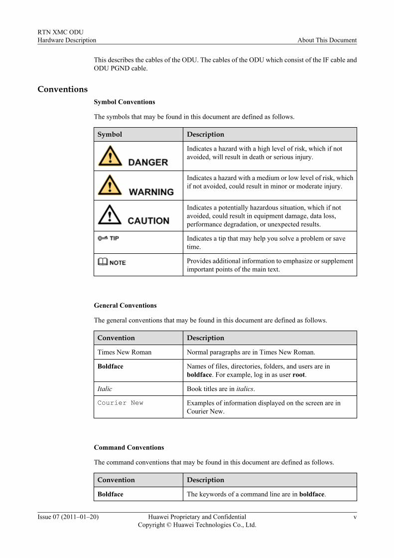
ConventionsSymbol Conventions
The symbols that may be found in this document are defined as follows.
Symbol Description
Indicates a hazard with a high level of risk, which if notavoided, will result in death or serious injury.
Indicates a hazard with a medium or low level of risk, whichif not avoided, could result in minor or moderate injury.
Indicates a potentially hazardous situation, which if notavoided, could result in equipment damage, data loss,performance degradation, or unexpected results.
Indicates a tip that may help you solve a problem or savetime.
Provides additional information to emphasize or supplementimportant points of the main text.
General Conventions
The general conventions that may be found in this document are defined as follows.
Convention Description
Times New Roman Normal paragraphs are in Times New Roman.
Boldface Names of files, directories, folders, and users are inboldface. For example, log in as user root.
Italic Book titles are in italics.
Courier New Examples of information displayed on the screen are inCourier New.
Command Conventions
The command conventions that may be found in this document are defined as follows.
Convention Description
Boldface The keywords of a command line are in boldface.
RTN XMC ODUHardware Description About This Document
Issue 07 (2011–01–20) Huawei Proprietary and ConfidentialCopyright © Huawei Technologies Co., Ltd.
v
Convention Description
Italic Command arguments are in italics.
[ ] Items (keywords or arguments) in brackets [ ] are optional.
{ x | y | ... } Optional items are grouped in braces and separated byvertical bars. One item is selected.
[ x | y | ... ] Optional items are grouped in brackets and separated byvertical bars. One item is selected or no item is selected.
{ x | y | ... }* Optional items are grouped in braces and separated byvertical bars. A minimum of one item or a maximum of allitems can be selected.
[ x | y | ... ]* Optional items are grouped in brackets and separated byvertical bars. Several items or no item can be selected.
GUI Conventions
The GUI conventions that may be found in this document are defined as follows.
Convention Description
Boldface Buttons, menus, parameters, tabs, window, and dialog titlesare in boldface. For example, click OK.
> Multi-level menus are in boldface and separated by the ">"signs. For example, choose File > Create > Folder.
Keyboard Operations
The keyboard operations that may be found in this document are defined as follows.
Format Description
Key Press the key. For example, press Enter and press Tab.
Key 1+Key 2 Press the keys concurrently. For example, pressing Ctrl+Alt+A means the three keys should be pressed concurrently.
Key 1, Key 2 Press the keys in turn. For example, pressing Alt, A meansthe two keys should be pressed in turn.
Mouse Operations
The mouse operations that may be found in this document are defined as follows.
About This DocumentRTN XMC ODU
Hardware Description
vi Huawei Proprietary and ConfidentialCopyright © Huawei Technologies Co., Ltd.
Issue 07 (2011–01–20)
Action Description
Click Select and release the primary mouse button without movingthe pointer.
Double-click Press the primary mouse button twice continuously andquickly without moving the pointer.
Drag Press and hold the primary mouse button and move thepointer to a certain position.
RTN XMC ODUHardware Description About This Document
Issue 07 (2011–01–20) Huawei Proprietary and ConfidentialCopyright © Huawei Technologies Co., Ltd.
vii

Contents
About This Document...................................................................................................................iii
1 Outdoor Unit (ODU)..................................................................................................................1-11.1 Device Type.................................................................................................................................................... 1-31.2 Appearance......................................................................................................................................................1-31.3 Functions.........................................................................................................................................................1-41.4 Working Principles..........................................................................................................................................1-51.5 Installation Mode.............................................................................................................................................1-61.6 Interfaces.........................................................................................................................................................1-81.7 Labels............................................................................................................................................................1-101.8 Technical Specifications...............................................................................................................................1-12
1.8.1 XMC-1 ODU........................................................................................................................................1-121.8.2 XMC-2 ODU........................................................................................................................................1-18
2 Hybrid coupler............................................................................................................................2-12.1 Device Type.................................................................................................................................................... 2-22.2 Appearance......................................................................................................................................................2-22.3 Functions.........................................................................................................................................................2-32.4 Working Principles..........................................................................................................................................2-32.5 Interfaces.........................................................................................................................................................2-32.6 Label................................................................................................................................................................2-52.7 Technical Specifications................................................................................................................................. 2-7
3 Separate Mounting Components............................................................................................3-13.1 ODU Separate Mounting Bracket...................................................................................................................3-23.2 Flexible Waveguide.........................................................................................................................................3-2
4 Antennas......................................................................................................................................4-14.1 Device Type.................................................................................................................................................... 4-24.2 Functions.........................................................................................................................................................4-44.3 Working Principles..........................................................................................................................................4-44.4 Interfaces.........................................................................................................................................................4-64.5 Antenna Diameters..........................................................................................................................................4-64.6 Technical Specifications................................................................................................................................. 4-7
5 Antenna Adapter........................................................................................................................5-1
RTN XMC ODUHardware Description Contents
Issue 07 (2011–01–20) Huawei Proprietary and ConfidentialCopyright © Huawei Technologies Co., Ltd.
ix
6 Cables...........................................................................................................................................6-16.1 IF Cable...........................................................................................................................................................6-26.2 PGND Cable of the ODU................................................................................................................................6-3
ContentsRTN XMC ODU
Hardware Description
x Huawei Proprietary and ConfidentialCopyright © Huawei Technologies Co., Ltd.
Issue 07 (2011–01–20)
Figures
Figure 1-1 Appearance of the ODU..................................................................................................................... 1-3Figure 1-2 Working principles of the ODU......................................................................................................... 1-5Figure 1-3 Direct mounting mode........................................................................................................................1-6Figure 1-4 Separate mounting mode using a single-polarized antenna................................................................1-7Figure 1-5 Separate mounting mode using a dual-polarized antenna.................................................................. 1-8Figure 1-6 Interfaces of the ODU.........................................................................................................................1-9Figure 1-7 Nameplate label of the ODU............................................................................................................1-10Figure 2-1 Appearance of the hybrid coupler.......................................................................................................2-2Figure 2-2 Interfaces of the hybrid coupler..........................................................................................................2-4Figure 2-3 Label of the hybrid coupler.................................................................................................................2-5Figure 3-1 Appearance of the ODU separate mounting bracket..........................................................................3-2Figure 3-2 Appearance of the flexible waveguide............................................................................................... 3-3Figure 4-1 Feed boom of the single-polarized antenna with the diameter less than or equal to 1.8 m................4-2Figure 4-2 Feed boom of the single-polarized antenna with the diameter greater than 1.8 m.............................4-3Figure 4-3 Feed booms of the dual-polarized antenna.........................................................................................4-3Figure 4-4 Structure of the antenna......................................................................................................................4-4Figure 4-5 Polarization directions supported by the rectangular waveguide.......................................................4-5Figure 5-1 Appearance and interfaces of the antenna adapter............................................................................. 5-1Figure 5-2 Nameplate label of the antenna adapter..............................................................................................5-2Figure 6-1 Diagram of the IF cable......................................................................................................................6-2Figure 6-2 Diagram of the ODU protection ground cable .................................................................................. 6-3
RTN XMC ODUHardware Description Figures
Issue 07 (2011–01–20) Huawei Proprietary and ConfidentialCopyright © Huawei Technologies Co., Ltd.
xi

Tables
Table 1-1 Performance attributes of the ODU......................................................................................................1-3Table 1-2 Appearance description of the ODU....................................................................................................1-4Table 1-3 Interfaces of the ODU..........................................................................................................................1-9Table 1-4 Meanings of the parameters on the nameplate label..........................................................................1-10Table 1-5 Bar code, radiation label, and overtemperature label.........................................................................1-11Table 1-6 Working formats of the ODU (XMC-1 ODU)...................................................................................1-12Table 1-7 Working frequency bands of the ODU (XMC-1 ODU).....................................................................1-12Table 1-8 Transceiver specifications of the ODU (XMC-1 ODU)....................................................................1-13Table 1-9 IF specifications of the ODU (XMC-1 ODU)....................................................................................1-13Table 1-10 Integrated system specifications of the ODU (XMC-1 ODU).........................................................1-14Table 1-11 Information about the 7 GHz frequency band (XMC-1 ODU)........................................................1-14Table 1-12 Information about the 8 GHz frequency band (XMC-1 ODU)........................................................1-16Table 1-13 Information about the 13 GHz frequency band (XMC-1 ODU)......................................................1-16Table 1-14 Information about the 15 GHz frequency band (XMC-1 ODU)......................................................1-17Table 1-15 Information about the 18 GHz frequency band (XMC-1 ODU)......................................................1-17Table 1-16 Information about the 23 GHz frequency band (XMC-1 ODU)......................................................1-17Table 1-17 Working formats of the ODU (XMC-2 ODU).................................................................................1-18Table 1-18 Working frequency bands of the ODU (XMC-2 ODU)...................................................................1-18Table 1-19 Transceiver specifications of the ODU (XMC-2 ODU)..................................................................1-19Table 1-20 IF specifications of the ODU (XMC-2 ODU)..................................................................................1-20Table 1-21 Integrated system specifications of the ODU (XMC-2 ODU).........................................................1-20Table 1-22 Information about the 7 GHz frequency band (XMC-2 ODU)........................................................1-21Table 1-23 Information about the 8 GHz frequency band (XMC-2 ODU)........................................................1-22Table 1-24 Information about the 13 GHz frequency band (XMC-2 ODU)......................................................1-23Table 1-25 Information about the 15 GHz frequency band (XMC-2 ODU)......................................................1-23Table 1-26 Information about the 18 GHz frequency band (XMC-2 ODU)......................................................1-24Table 1-27 Information about the 23 GHz frequency band (XMC-2 ODU)......................................................1-24Table 1-28 Information about the 26 GHz frequency band (XMC-2 ODU)......................................................1-25Table 1-29 Information about the 38 GHz frequency band (XMC-2 ODU)......................................................1-25Table 2-1 Appearance description of the hybrid coupler.....................................................................................2-2Table 2-2 Interface description of the hybrid coupler..........................................................................................2-4Table 2-3 Meaning of the hybrid coupler label....................................................................................................2-5Table 2-4 Technical specifications of the hybrid coupler....................................................................................2-7
RTN XMC ODUHardware Description Tables
Issue 07 (2011–01–20) Huawei Proprietary and ConfidentialCopyright © Huawei Technologies Co., Ltd.
xiii
Table 3-1 Technical specifications of the flexible waveguide.............................................................................3-3Table 4-1 Specifications for the feed boom interface of an antenna....................................................................4-6Table 4-2 Diameter of the single-polarized antenna.............................................................................................4-6Table 4-3 Diameter of the dual-polarized antenna...............................................................................................4-7Table 5-1 Technical specifications of the antenna adapter...................................................................................5-1Table 5-2 Meanings of the parameters on the nameplate label............................................................................5-3Table 5-3 Bar code...............................................................................................................................................5-3Table 6-1 Performance of the IF cable.................................................................................................................6-3
TablesRTN XMC ODU
Hardware Description
xiv Huawei Proprietary and ConfidentialCopyright © Huawei Technologies Co., Ltd.
Issue 07 (2011–01–20)
1 Outdoor Unit (ODU)
About This Chapter
This describes the ODU, an outdoor unit of the digital microwave transmission system. It is usedto convert and amplify signals. The ODUs that are described in this document are the RTN XMCODUs.
1.1 Device TypeThis describes the types of the ODU. The XMC-1 ODU is a type of low capacity for PDH ODU.The XMC-2 ODU is a type of ODU in high power.
1.2 AppearanceThis describes the appearance of the ODU. The ODU is an outdoor integrated device that adoptsthe unified design.
1.3 FunctionsThe ODU, a microwave RF unit, has the function of frequency conversion and poweramplification. The ODU determines microwave frequencies of the transmitted and receivedsignals and is not affected by transmission service types such as the TDM serivce and Ethernetservice.
1.4 Working PrinciplesThis describes the working principles of the ODU. The working principles of different types ofODUs are similar.
1.5 Installation ModeThe ODU can be installed on the antenna in two modes: direct mounting mode and separatemounting mode.
1.6 InterfacesThis describes the interfaces of the ODU. The interfaces of the ODU consist of the antennainterface, IF interface, RSSI interface, and grounding screw.
1.7 LabelsThis describes the labels attached to the ODU. The following labels are attached to the ODU:nameplate label, bar code, radiation label, and overtemperature label. These labels are used toidentify the device information, radiation alarm, and overtemperature alarm of the ODU.
1.8 Technical Specifications
RTN XMC ODUHardware Description 1 Outdoor Unit (ODU)
Issue 07 (2011–01–20) Huawei Proprietary and ConfidentialCopyright © Huawei Technologies Co., Ltd.
1-1
This describes the technical specifications of the ODU. The technical specifications of the ODUconsist of working formats, frequency bands, transceiver specifications, IF specifications,integrated system specifications, and frequency information.
1 Outdoor Unit (ODU)RTN XMC ODU
Hardware Description
1-2 Huawei Proprietary and ConfidentialCopyright © Huawei Technologies Co., Ltd.
Issue 07 (2011–01–20)
1.1 Device TypeThis describes the types of the ODU. The XMC-1 ODU is a type of low capacity for PDH ODU.The XMC-2 ODU is a type of ODU in high power.
Table 1-1 shows the performance and attributes of the ODU.
Table 1-1 Performance attributes of the ODU
Item XMC-1 ODU XMC-2 ODU
ODU type Low capacity for PDH ODU ODU in high power
Frequencyband
7 GHz, 8 GHz, 13 GHz, 15 GHz, 18GHz, and 23 GHz
7 GHz, 8 GHz, 13 GHz, 15 GHz, 18GHz, 23 GHz, 26 GHz and 38 GHz
Microwavemodulation format
QPSK and 16QAM QPSK, 16QAM, 32QAM, 64QAM,128QAM, and 256QAM
Channelspacing
3.5 MHz, 7 MHz, 14 MHz, and 28MHz
7 MHz, 14 MHz, 28 MHz, and 56 MHz(7/13/15/18/23/26/38 GHz frequencyband)7 MHz, 14 MHz, 28 MHz, 40 MHz,and 56 MHz (8 GHz frequency band)
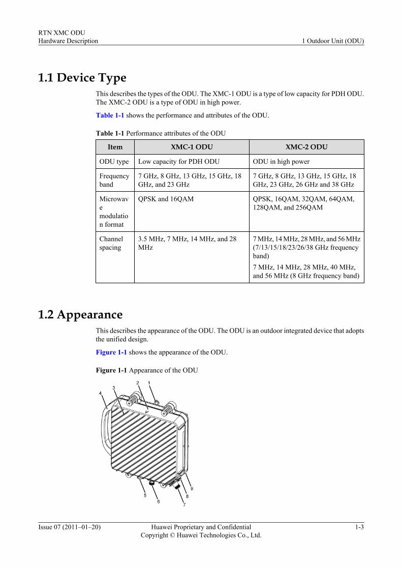
1.2 AppearanceThis describes the appearance of the ODU. The ODU is an outdoor integrated device that adoptsthe unified design.
Figure 1-1 shows the appearance of the ODU.
Figure 1-1 Appearance of the ODU
RTN XMC ODUHardware Description 1 Outdoor Unit (ODU)
Issue 07 (2011–01–20) Huawei Proprietary and ConfidentialCopyright © Huawei Technologies Co., Ltd.
1-3
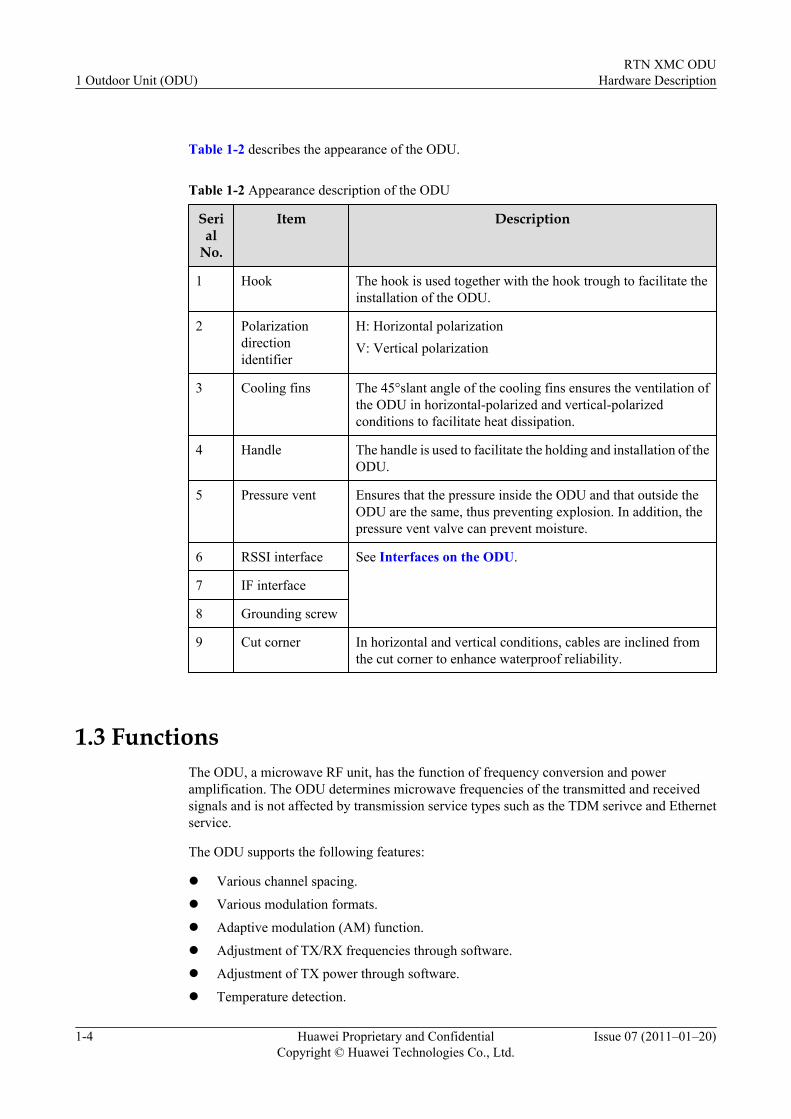
Table 1-2 describes the appearance of the ODU.
Table 1-2 Appearance description of the ODU
Serial
No.
Item Description
1 Hook The hook is used together with the hook trough to facilitate theinstallation of the ODU.
2 Polarizationdirectionidentifier
H: Horizontal polarizationV: Vertical polarization
3 Cooling fins The 45°slant angle of the cooling fins ensures the ventilation ofthe ODU in horizontal-polarized and vertical-polarizedconditions to facilitate heat dissipation.
4 Handle The handle is used to facilitate the holding and installation of theODU.
5 Pressure vent Ensures that the pressure inside the ODU and that outside theODU are the same, thus preventing explosion. In addition, thepressure vent valve can prevent moisture.
6 RSSI interface See Interfaces on the ODU.
7 IF interface
8 Grounding screw
9 Cut corner In horizontal and vertical conditions, cables are inclined fromthe cut corner to enhance waterproof reliability.
1.3 FunctionsThe ODU, a microwave RF unit, has the function of frequency conversion and poweramplification. The ODU determines microwave frequencies of the transmitted and receivedsignals and is not affected by transmission service types such as the TDM serivce and Ethernetservice.
The ODU supports the following features:
l Various channel spacing.
l Various modulation formats.
l Adaptive modulation (AM) function.
l Adjustment of TX/RX frequencies through software.
l Adjustment of TX power through software.
l Temperature detection.
1 Outdoor Unit (ODU)RTN XMC ODU
Hardware Description
1-4 Huawei Proprietary and ConfidentialCopyright © Huawei Technologies Co., Ltd.
Issue 07 (2011–01–20)
l TX power detection.l RX power detection.l Received Signal Strength Indicator (RSSI) interface:
The ODU has an RSSI interface, which indicates the RX power in voltage.l Mute transmission.l Automatic Transmit Power Control (ATPC).l Automatic Gain Control (AGC) function of received signals:
The ODU automatically adjusts the channel gain according to the level of received signals.
1.4 Working PrinciplesThis describes the working principles of the ODU. The working principles of different types ofODUs are similar.
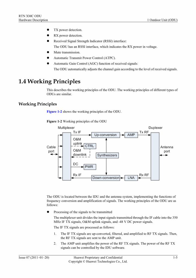
Working PrinciplesFigure 1-2 shows the working principles of the ODU.
Figure 1-2 Working principles of the ODU
The ODU is located between the IDU and the antenna system, implementing the functions offrequency conversion and amplification of signals. The working principles of the ODU are asfollows:
l Processing of the signals to be transmittedThe multiplexer unit divides the input signals transmitted through the IF cable into the 350MHz IF TX signals, O&M uplink signals, and -48 V DC power signals.The IF TX signals are processed as follows:
1. The IF TX signals are up-converted, filtered, and amplified to RF TX signals. Then,the RF TX signals are sent to the AMP unit.
2. The AMP unit amplifies the power of the RF TX signals. The power of the RF TXsignals can be controlled by the IDU software.
RTN XMC ODUHardware Description 1 Outdoor Unit (ODU)
Issue 07 (2011–01–20) Huawei Proprietary and ConfidentialCopyright © Huawei Technologies Co., Ltd.
1-5
3. The amplified RF TX signals are sent to the antenna through the duplexer isolationunit.
The O&M uplink signals are the 5.5 MHz signals modulated in Amplitude Shift Keying(ASK) mode. The signals are sent to the CTRL unit and demodulated.The -48 V DC power signals are sent to the PWR unit. The PWR generates secondary powersupplies for each module of the ODU.
l Processing of the received signals
1. The duplexer isolation unit separates the RF input signals from other signals receivedby the antenna.
2. The RF signals are amplified through the Low Noise Amplifier (LNA) unit.3. The amplified RF signals are down-converted, filtered, and amplified to 140 MHz IF
RX signals and transmitted to the multiplexer unit.4. The multiplexer unit combines the IF RX signals and O&M downlink signals and then
transmits the combined signals to the IDU through IF cable.
The CTRL unit performs the ASK modulation on the O&M downlink signals to generate10 MHz signals. The modulated signals are transmitted to the multiplexer unit. The CTRLunit provides the RSSI interface and monitors the RX level through the RSSI circuit.
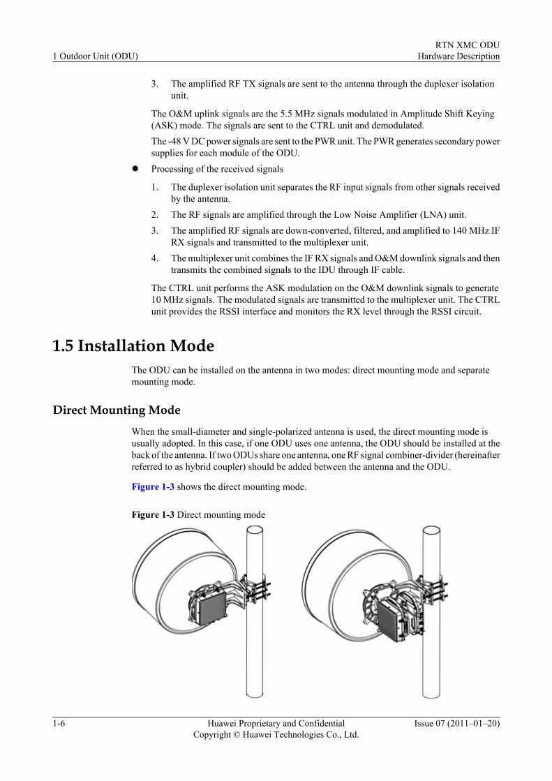
1.5 Installation ModeThe ODU can be installed on the antenna in two modes: direct mounting mode and separatemounting mode.
Direct Mounting Mode
When the small-diameter and single-polarized antenna is used, the direct mounting mode isusually adopted. In this case, if one ODU uses one antenna, the ODU should be installed at theback of the antenna. If two ODUs share one antenna, one RF signal combiner-divider (hereinafterreferred to as hybrid coupler) should be added between the antenna and the ODU.
Figure 1-3 shows the direct mounting mode.
Figure 1-3 Direct mounting mode
1 Outdoor Unit (ODU)RTN XMC ODU
Hardware Description
1-6 Huawei Proprietary and ConfidentialCopyright © Huawei Technologies Co., Ltd.
Issue 07 (2011–01–20)
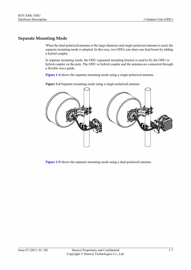
Separate Mounting ModeWhen the dual-polarized antenna or the large-diameter and single-polarized antenna is used, theseparate mounting mode is adopted. In this case, two ODUs can share one feed boom by addinga hybrid coupler.
In separate mounting mode, the ODU separated mounting bracket is used to fix the ODU orhybrid coupler on the pole. The ODU or hybrid coupler and the antenna are connected througha flexible wave guide.
Figure 1-4 shows the separate mounting mode using a single-polarized antenna.
Figure 1-4 Separate mounting mode using a single-polarized antenna
Figure 1-5 shows the separate mounting mode using a dual-polarized antenna.
RTN XMC ODUHardware Description 1 Outdoor Unit (ODU)
Issue 07 (2011–01–20) Huawei Proprietary and ConfidentialCopyright © Huawei Technologies Co., Ltd.
1-7
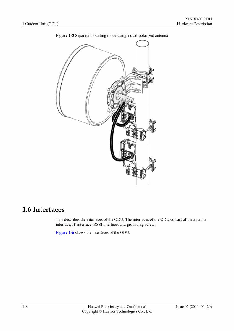
Figure 1-5 Separate mounting mode using a dual-polarized antenna
1.6 InterfacesThis describes the interfaces of the ODU. The interfaces of the ODU consist of the antennainterface, IF interface, RSSI interface, and grounding screw.
Figure 1-6 shows the interfaces of the ODU.
1 Outdoor Unit (ODU)RTN XMC ODU
Hardware Description
1-8 Huawei Proprietary and ConfidentialCopyright © Huawei Technologies Co., Ltd.
Issue 07 (2011–01–20)
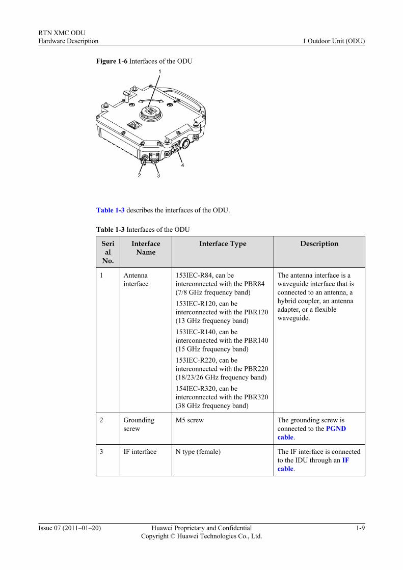
Figure 1-6 Interfaces of the ODU
Table 1-3 describes the interfaces of the ODU.
Table 1-3 Interfaces of the ODU
Serial
No.
InterfaceName
Interface Type Description
1 Antennainterface
153IEC-R84, can beinterconnected with the PBR84(7/8 GHz frequency band)153IEC-R120, can beinterconnected with the PBR120(13 GHz frequency band)153IEC-R140, can beinterconnected with the PBR140(15 GHz frequency band)153IEC-R220, can beinterconnected with the PBR220(18/23/26 GHz frequency band)154IEC-R320, can beinterconnected with the PBR320(38 GHz frequency band)
The antenna interface is awaveguide interface that isconnected to an antenna, ahybrid coupler, an antennaadapter, or a flexiblewaveguide.
2 Groundingscrew
M5 screw The grounding screw isconnected to the PGNDcable.
3 IF interface N type (female) The IF interface is connectedto the IDU through an IFcable.
RTN XMC ODUHardware Description 1 Outdoor Unit (ODU)
Issue 07 (2011–01–20) Huawei Proprietary and ConfidentialCopyright © Huawei Technologies Co., Ltd.
1-9
Serial
No.
InterfaceName
Interface Type Description
4 RSSI interface BNC type (female) The received signal strengthof the ODU can be calculatedbased on the voltage of theinterface that is measuredthrough a multimeter.
1.7 LabelsThis describes the labels attached to the ODU. The following labels are attached to the ODU:nameplate label, bar code, radiation label, and overtemperature label. These labels are used toidentify the device information, radiation alarm, and overtemperature alarm of the ODU.
The ODU labels and the meanings of the labels are describes as follows:
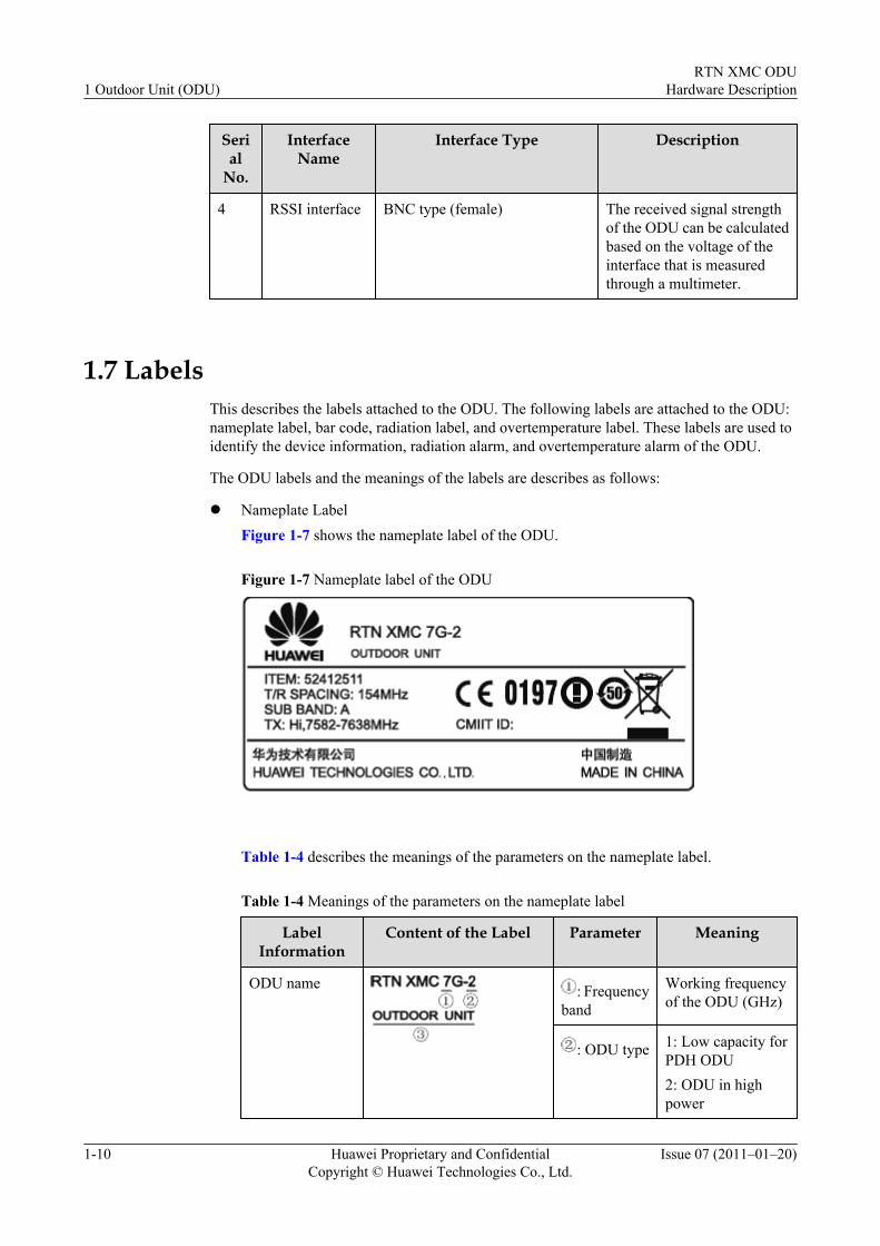
l Nameplate LabelFigure 1-7 shows the nameplate label of the ODU.
Figure 1-7 Nameplate label of the ODU
Table 1-4 describes the meanings of the parameters on the nameplate label.
Table 1-4 Meanings of the parameters on the nameplate label
LabelInformation
Content of the Label Parameter Meaning
ODU name : Frequencyband
Working frequencyof the ODU (GHz)
: ODU type 1: Low capacity forPDH ODU2: ODU in highpower
1 Outdoor Unit (ODU)RTN XMC ODU
Hardware Description
1-10 Huawei Proprietary and ConfidentialCopyright © Huawei Technologies Co., Ltd.
Issue 07 (2011–01–20)
LabelInformation
Content of the Label Parameter Meaning
:Componentname
Indicates that thecomponent is anODU
ODU code(ITEM)
- Used to identify thetype of the ODU
ODU T/Rspacing(T/R SPACING)
- Spacing betweenRX and TXfrequencies (MHz)
ODU subband(SUB BAND)
- Frequencysubbands numberedwith letters
TX statusinformationabout the ODU(TX)
: TX high/low station
Hi: TX high station
Lo: TX low station
: Range ofthe TXfrequency
Range of the ODUTX frequency(MHz)
CMIIT ID - - ID of RadioTransmissionEquipment TypeApprovalCertificate(domestic)
l Bar Code, Radiation Label, and Overtemperature Label
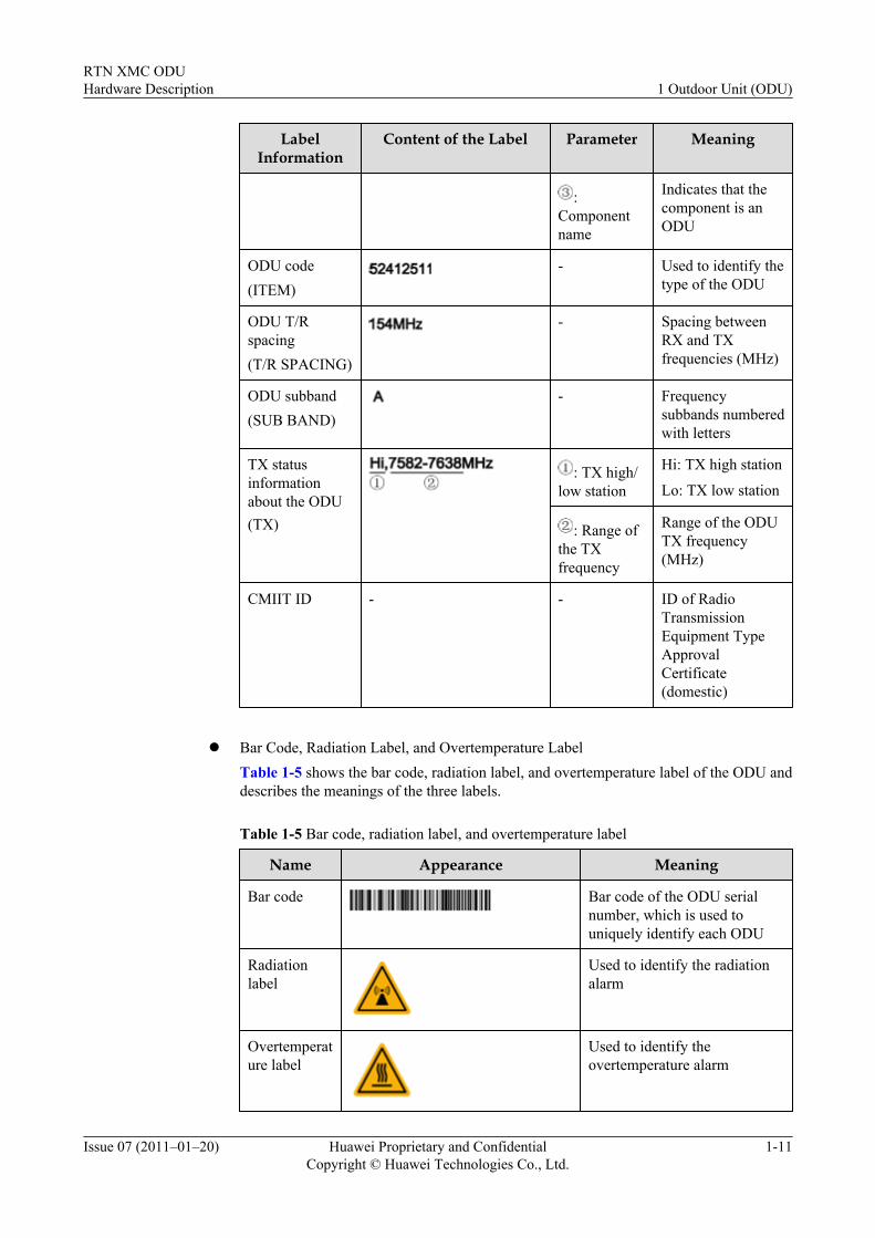
Table 1-5 shows the bar code, radiation label, and overtemperature label of the ODU anddescribes the meanings of the three labels.
Table 1-5 Bar code, radiation label, and overtemperature label
Name Appearance Meaning
Bar code Bar code of the ODU serialnumber, which is used touniquely identify each ODU
Radiationlabel
Used to identify the radiationalarm
Overtemperature label
Used to identify theovertemperature alarm
RTN XMC ODUHardware Description 1 Outdoor Unit (ODU)
Issue 07 (2011–01–20) Huawei Proprietary and ConfidentialCopyright © Huawei Technologies Co., Ltd.
1-11
1.8 Technical SpecificationsThis describes the technical specifications of the ODU. The technical specifications of the ODUconsist of working formats, frequency bands, transceiver specifications, IF specifications,integrated system specifications, and frequency information.
1.8.1 XMC-1 ODUThis describes the technical specifications of the XMC-1 ODU.
1.8.2 XMC-2 ODUThis describes the technical specifications of the XMC-2 ODU.
1.8.1 XMC-1 ODUThis describes the technical specifications of the XMC-1 ODU.
Working Formats
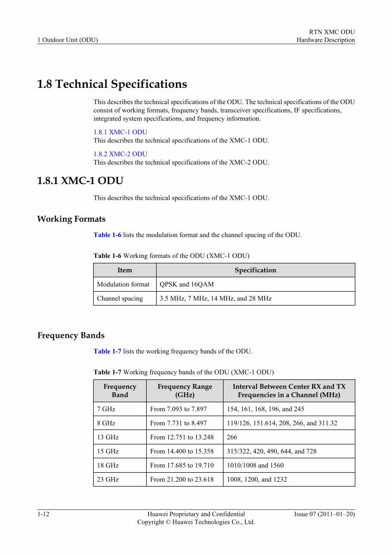
Table 1-6 lists the modulation format and the channel spacing of the ODU.
Table 1-6 Working formats of the ODU (XMC-1 ODU)
Item Specification
Modulation format QPSK and 16QAM
Channel spacing 3.5 MHz, 7 MHz, 14 MHz, and 28 MHz
Frequency Bands
Table 1-7 lists the working frequency bands of the ODU.
Table 1-7 Working frequency bands of the ODU (XMC-1 ODU)
FrequencyBand
Frequency Range(GHz)
Interval Between Center RX and TXFrequencies in a Channel (MHz)
7 GHz From 7.093 to 7.897 154, 161, 168, 196, and 245
8 GHz From 7.731 to 8.497 119/126, 151.614, 208, 266, and 311.32
13 GHz From 12.751 to 13.248 266
15 GHz From 14.400 to 15.358 315/322, 420, 490, 644, and 728
18 GHz From 17.685 to 19.710 1010/1008 and 1560
23 GHz From 21.200 to 23.618 1008, 1200, and 1232
1 Outdoor Unit (ODU)RTN XMC ODU
Hardware Description
1-12 Huawei Proprietary and ConfidentialCopyright © Huawei Technologies Co., Ltd.
Issue 07 (2011–01–20)
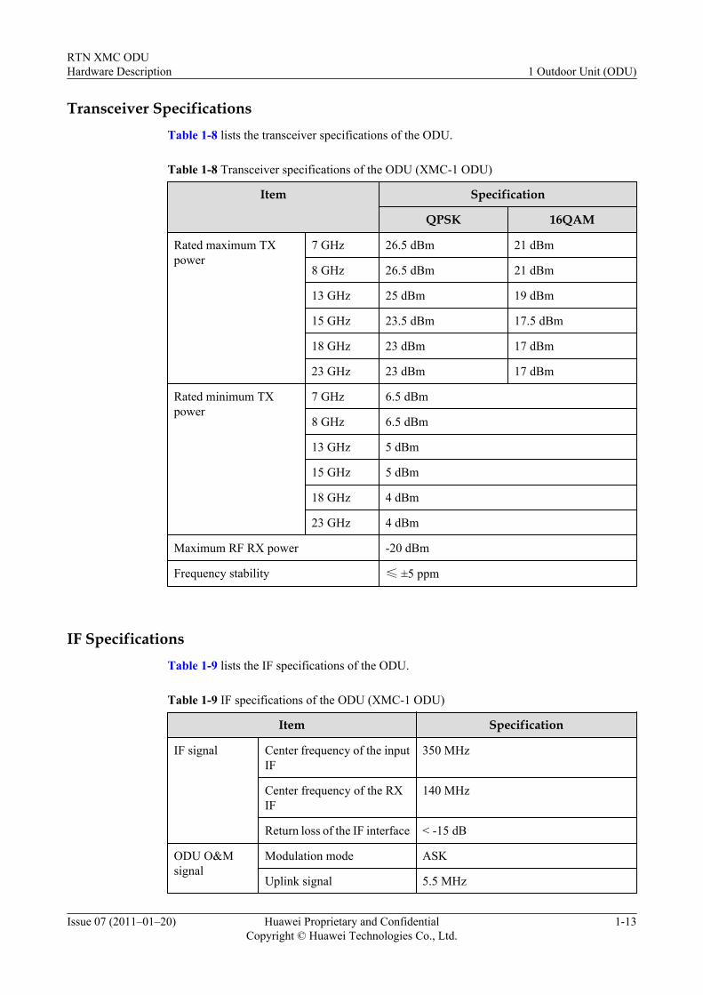
Transceiver SpecificationsTable 1-8 lists the transceiver specifications of the ODU.
Table 1-8 Transceiver specifications of the ODU (XMC-1 ODU)
Item Specification
QPSK 16QAM
Rated maximum TXpower
7 GHz 26.5 dBm 21 dBm
8 GHz 26.5 dBm 21 dBm
13 GHz 25 dBm 19 dBm
15 GHz 23.5 dBm 17.5 dBm
18 GHz 23 dBm 17 dBm
23 GHz 23 dBm 17 dBm
Rated minimum TXpower
7 GHz 6.5 dBm
8 GHz 6.5 dBm
13 GHz 5 dBm
15 GHz 5 dBm
18 GHz 4 dBm
23 GHz 4 dBm
Maximum RF RX power -20 dBm
Frequency stability ≤ ±5 ppm
IF SpecificationsTable 1-9 lists the IF specifications of the ODU.
Table 1-9 IF specifications of the ODU (XMC-1 ODU)
Item Specification
IF signal Center frequency of the inputIF
350 MHz
Center frequency of the RXIF
140 MHz
Return loss of the IF interface < -15 dB
ODU O&Msignal
Modulation mode ASK
Uplink signal 5.5 MHz
RTN XMC ODUHardware Description 1 Outdoor Unit (ODU)
Issue 07 (2011–01–20) Huawei Proprietary and ConfidentialCopyright © Huawei Technologies Co., Ltd.
1-13
Item Specification
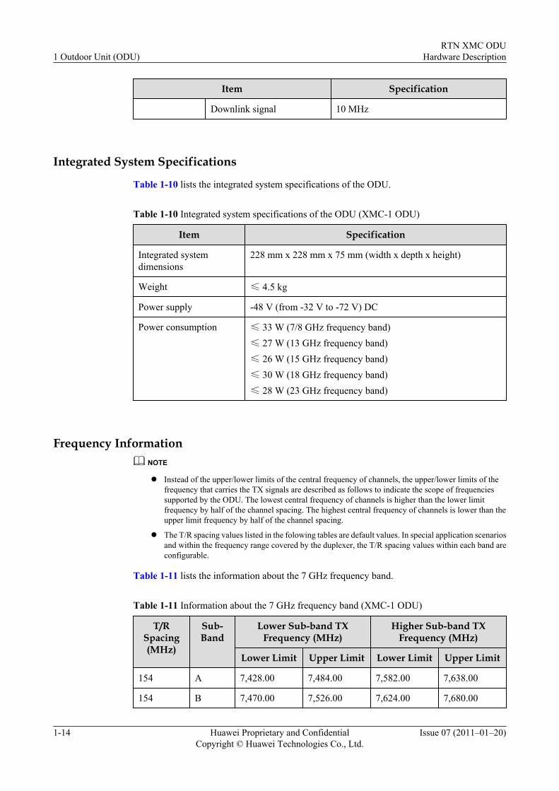
Downlink signal 10 MHz
Integrated System Specifications
Table 1-10 lists the integrated system specifications of the ODU.
Table 1-10 Integrated system specifications of the ODU (XMC-1 ODU)
Item Specification
Integrated systemdimensions
228 mm x 228 mm x 75 mm (width x depth x height)
Weight ≤ 4.5 kg
Power supply -48 V (from -32 V to -72 V) DC
Power consumption ≤ 33 W (7/8 GHz frequency band)≤ 27 W (13 GHz frequency band)≤ 26 W (15 GHz frequency band)≤ 30 W (18 GHz frequency band)≤ 28 W (23 GHz frequency band)
Frequency InformationNOTE
l Instead of the upper/lower limits of the central frequency of channels, the upper/lower limits of thefrequency that carries the TX signals are described as follows to indicate the scope of frequenciessupported by the ODU. The lowest central frequency of channels is higher than the lower limitfrequency by half of the channel spacing. The highest central frequency of channels is lower than theupper limit frequency by half of the channel spacing.
l The T/R spacing values listed in the folowing tables are default values. In special application scenariosand within the frequency range covered by the duplexer, the T/R spacing values within each band areconfigurable.
Table 1-11 lists the information about the 7 GHz frequency band.
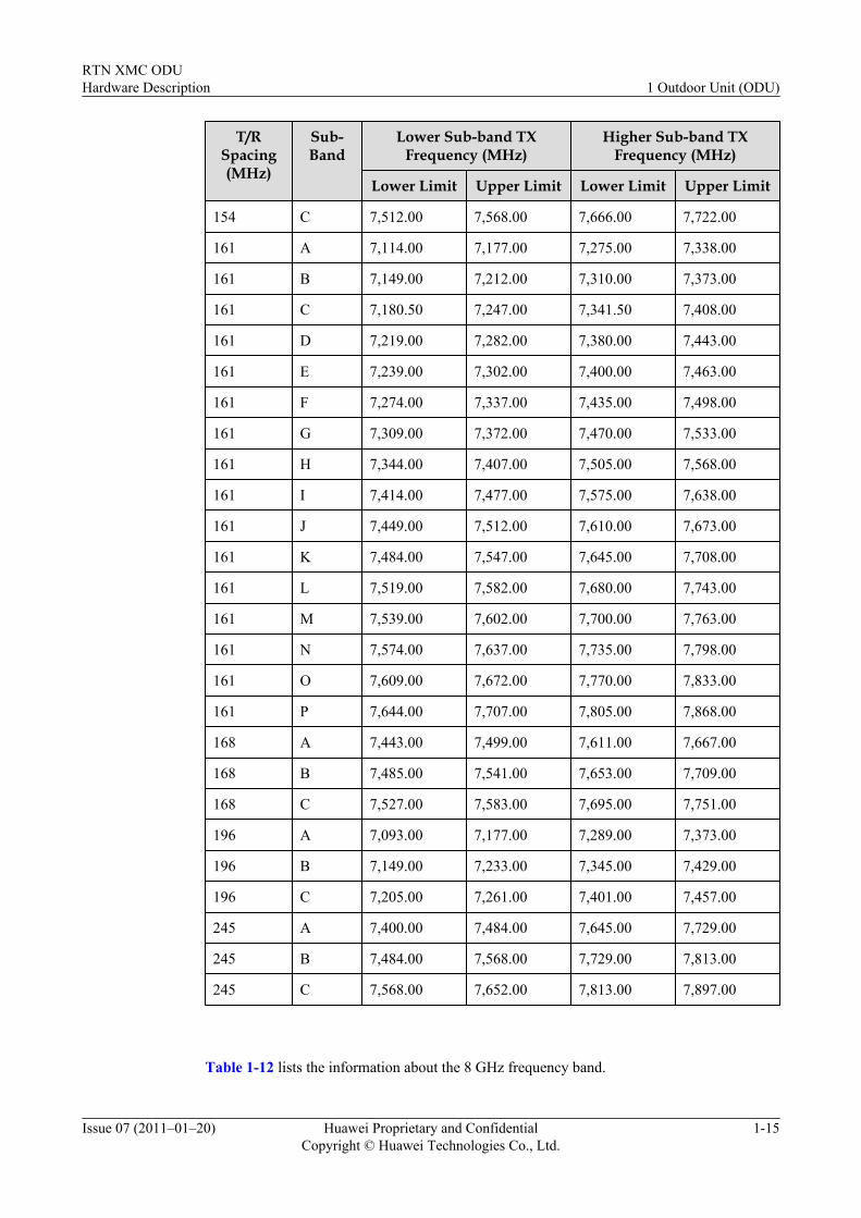
Table 1-11 Information about the 7 GHz frequency band (XMC-1 ODU)
T/RSpacing(MHz)
Sub-Band
Lower Sub-band TXFrequency (MHz)
Higher Sub-band TXFrequency (MHz)
Lower Limit Upper Limit Lower Limit Upper Limit
154 A 7,428.00 7,484.00 7,582.00 7,638.00
154 B 7,470.00 7,526.00 7,624.00 7,680.00
1 Outdoor Unit (ODU)RTN XMC ODU
Hardware Description
1-14 Huawei Proprietary and ConfidentialCopyright © Huawei Technologies Co., Ltd.
Issue 07 (2011–01–20)
T/RSpacing(MHz)
Sub-Band
Lower Sub-band TXFrequency (MHz)
Higher Sub-band TXFrequency (MHz)
Lower Limit Upper Limit Lower Limit Upper Limit
154 C 7,512.00 7,568.00 7,666.00 7,722.00
161 A 7,114.00 7,177.00 7,275.00 7,338.00
161 B 7,149.00 7,212.00 7,310.00 7,373.00
161 C 7,180.50 7,247.00 7,341.50 7,408.00
161 D 7,219.00 7,282.00 7,380.00 7,443.00
161 E 7,239.00 7,302.00 7,400.00 7,463.00
161 F 7,274.00 7,337.00 7,435.00 7,498.00
161 G 7,309.00 7,372.00 7,470.00 7,533.00
161 H 7,344.00 7,407.00 7,505.00 7,568.00
161 I 7,414.00 7,477.00 7,575.00 7,638.00
161 J 7,449.00 7,512.00 7,610.00 7,673.00
161 K 7,484.00 7,547.00 7,645.00 7,708.00
161 L 7,519.00 7,582.00 7,680.00 7,743.00
161 M 7,539.00 7,602.00 7,700.00 7,763.00
161 N 7,574.00 7,637.00 7,735.00 7,798.00
161 O 7,609.00 7,672.00 7,770.00 7,833.00
161 P 7,644.00 7,707.00 7,805.00 7,868.00
168 A 7,443.00 7,499.00 7,611.00 7,667.00
168 B 7,485.00 7,541.00 7,653.00 7,709.00
168 C 7,527.00 7,583.00 7,695.00 7,751.00
196 A 7,093.00 7,177.00 7,289.00 7,373.00
196 B 7,149.00 7,233.00 7,345.00 7,429.00
196 C 7,205.00 7,261.00 7,401.00 7,457.00
245 A 7,400.00 7,484.00 7,645.00 7,729.00
245 B 7,484.00 7,568.00 7,729.00 7,813.00
245 C 7,568.00 7,652.00 7,813.00 7,897.00
Table 1-12 lists the information about the 8 GHz frequency band.
RTN XMC ODUHardware Description 1 Outdoor Unit (ODU)
Issue 07 (2011–01–20) Huawei Proprietary and ConfidentialCopyright © Huawei Technologies Co., Ltd.
1-15
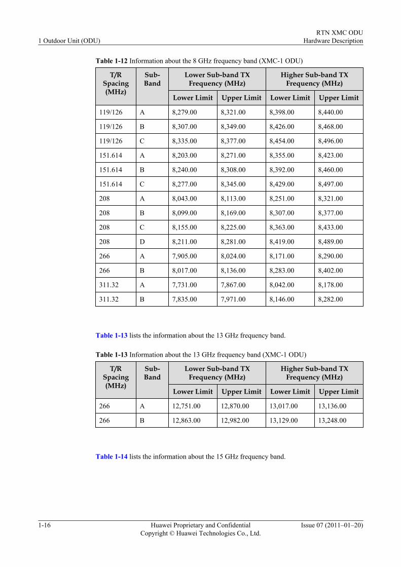
Table 1-12 Information about the 8 GHz frequency band (XMC-1 ODU)
T/RSpacing(MHz)
Sub-Band
Lower Sub-band TXFrequency (MHz)
Higher Sub-band TXFrequency (MHz)
Lower Limit Upper Limit Lower Limit Upper Limit
119/126 A 8,279.00 8,321.00 8,398.00 8,440.00
119/126 B 8,307.00 8,349.00 8,426.00 8,468.00
119/126 C 8,335.00 8,377.00 8,454.00 8,496.00
151.614 A 8,203.00 8,271.00 8,355.00 8,423.00
151.614 B 8,240.00 8,308.00 8,392.00 8,460.00
151.614 C 8,277.00 8,345.00 8,429.00 8,497.00
208 A 8,043.00 8,113.00 8,251.00 8,321.00
208 B 8,099.00 8,169.00 8,307.00 8,377.00
208 C 8,155.00 8,225.00 8,363.00 8,433.00
208 D 8,211.00 8,281.00 8,419.00 8,489.00
266 A 7,905.00 8,024.00 8,171.00 8,290.00
266 B 8,017.00 8,136.00 8,283.00 8,402.00
311.32 A 7,731.00 7,867.00 8,042.00 8,178.00
311.32 B 7,835.00 7,971.00 8,146.00 8,282.00
Table 1-13 lists the information about the 13 GHz frequency band.
Table 1-13 Information about the 13 GHz frequency band (XMC-1 ODU)
T/RSpacing(MHz)
Sub-Band
Lower Sub-band TXFrequency (MHz)
Higher Sub-band TXFrequency (MHz)
Lower Limit Upper Limit Lower Limit Upper Limit
266 A 12,751.00 12,870.00 13,017.00 13,136.00
266 B 12,863.00 12,982.00 13,129.00 13,248.00
Table 1-14 lists the information about the 15 GHz frequency band.
1 Outdoor Unit (ODU)RTN XMC ODU
Hardware Description
1-16 Huawei Proprietary and ConfidentialCopyright © Huawei Technologies Co., Ltd.
Issue 07 (2011–01–20)
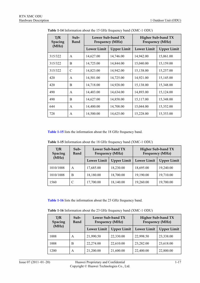
Table 1-14 Information about the 15 GHz frequency band (XMC-1 ODU)
T/RSpacing(MHz)
Sub-Band
Lower Sub-band TXFrequency (MHz)
Higher Sub-band TXFrequency (MHz)
Lower Limit Upper Limit Lower Limit Upper Limit
315/322 A 14,627.00 14,746.00 14,942.00 15,061.00
315/322 B 14,725.00 14,844.00 15,040.00 15,159.00
315/322 C 14,823.00 14,942.00 15,138.00 15,257.00
420 A 14,501.00 14,725.00 14,921.00 15,145.00
420 B 14,718.00 14,928.00 15,138.00 15,348.00
490 A 14,403.00 14,634.00 14,893.00 15,124.00
490 B 14,627.00 14,858.00 15,117.00 15,348.00
644 A 14,400.00 14,708.00 15,044.00 15,352.00
728 A 14,500.00 14,625.00 15,228.00 15,353.00
Table 1-15 lists the information about the 18 GHz frequency band.
Table 1-15 Information about the 18 GHz frequency band (XMC-1 ODU)
T/RSpacing(MHz)
Sub-Band
Lower Sub-band TXFrequency (MHz)
Higher Sub-band TXFrequency (MHz)
Lower Limit Upper Limit Lower Limit Upper Limit
1010/1008 A 17,685.00 18,230.00 18,695.00 19,240.00
1010/1008 B 18,180.00 18,700.00 19,190.00 19,710.00
1560 C 17,700.00 18,140.00 19,260.00 19,700.00
Table 1-16 lists the information about the 23 GHz frequency band.
Table 1-16 Information about the 23 GHz frequency band (XMC-1 ODU)
T/RSpacing(MHz)
Sub-Band
Lower Sub-band TXFrequency (MHz)
Higher Sub-band TXFrequency (MHz)
Lower Limit Upper Limit Lower Limit Upper Limit
1008 A 21,990.50 22,330.00 22,998.50 23,338.00
1008 B 22,274.00 22,610.00 23,282.00 23,618.00
1200 A 21,200.00 21,600.00 22,400.00 22,800.00
RTN XMC ODUHardware Description 1 Outdoor Unit (ODU)
Issue 07 (2011–01–20) Huawei Proprietary and ConfidentialCopyright © Huawei Technologies Co., Ltd.
1-17
T/RSpacing(MHz)
Sub-Band
Lower Sub-band TXFrequency (MHz)
Higher Sub-band TXFrequency (MHz)
Lower Limit Upper Limit Lower Limit Upper Limit
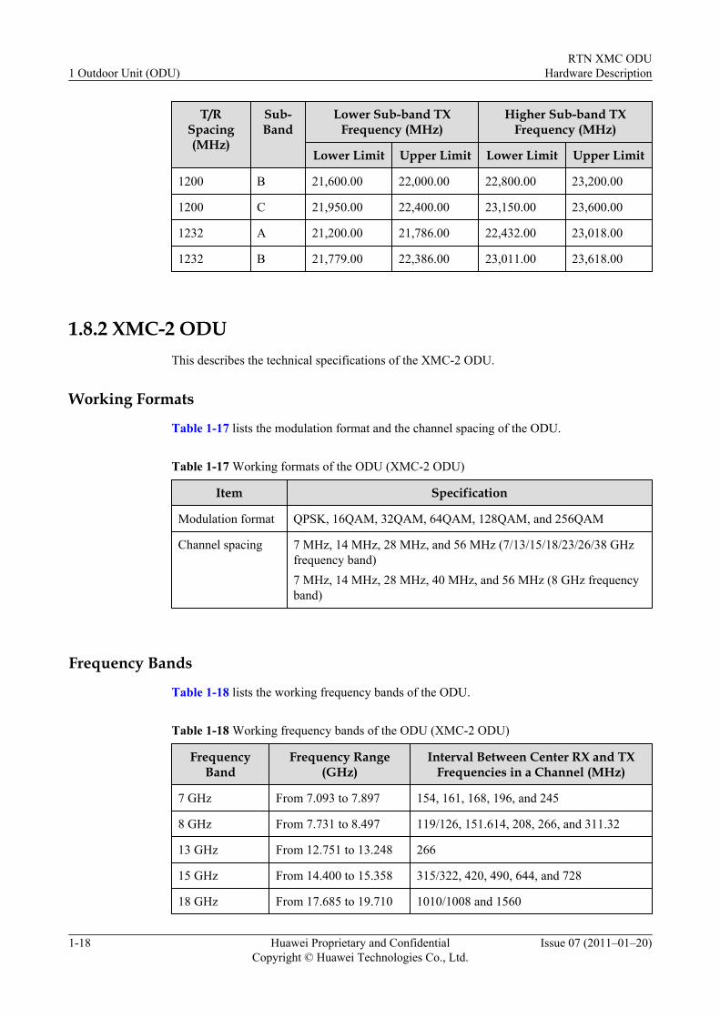
1200 B 21,600.00 22,000.00 22,800.00 23,200.00
1200 C 21,950.00 22,400.00 23,150.00 23,600.00
1232 A 21,200.00 21,786.00 22,432.00 23,018.00
1232 B 21,779.00 22,386.00 23,011.00 23,618.00
1.8.2 XMC-2 ODUThis describes the technical specifications of the XMC-2 ODU.
Working Formats
Table 1-17 lists the modulation format and the channel spacing of the ODU.
Table 1-17 Working formats of the ODU (XMC-2 ODU)
Item Specification
Modulation format QPSK, 16QAM, 32QAM, 64QAM, 128QAM, and 256QAM
Channel spacing 7 MHz, 14 MHz, 28 MHz, and 56 MHz (7/13/15/18/23/26/38 GHzfrequency band)7 MHz, 14 MHz, 28 MHz, 40 MHz, and 56 MHz (8 GHz frequencyband)
Frequency Bands
Table 1-18 lists the working frequency bands of the ODU.
Table 1-18 Working frequency bands of the ODU (XMC-2 ODU)
FrequencyBand
Frequency Range(GHz)
Interval Between Center RX and TXFrequencies in a Channel (MHz)
7 GHz From 7.093 to 7.897 154, 161, 168, 196, and 245
8 GHz From 7.731 to 8.497 119/126, 151.614, 208, 266, and 311.32
13 GHz From 12.751 to 13.248 266
15 GHz From 14.400 to 15.358 315/322, 420, 490, 644, and 728
18 GHz From 17.685 to 19.710 1010/1008 and 1560
1 Outdoor Unit (ODU)RTN XMC ODU
Hardware Description
1-18 Huawei Proprietary and ConfidentialCopyright © Huawei Technologies Co., Ltd.
Issue 07 (2011–01–20)
FrequencyBand
Frequency Range(GHz)
Interval Between Center RX and TXFrequencies in a Channel (MHz)
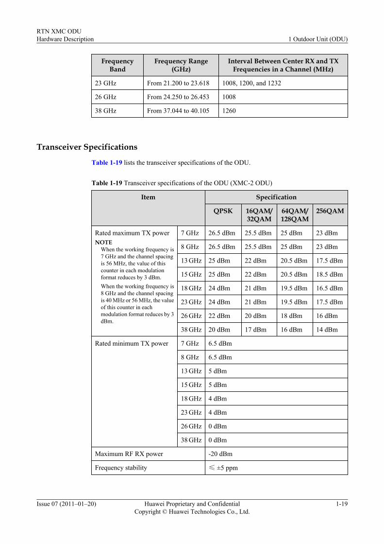
23 GHz From 21.200 to 23.618 1008, 1200, and 1232
26 GHz From 24.250 to 26.453 1008
38 GHz From 37.044 to 40.105 1260
Transceiver Specifications
Table 1-19 lists the transceiver specifications of the ODU.
Table 1-19 Transceiver specifications of the ODU (XMC-2 ODU)
Item Specification
QPSK 16QAM/32QAM
64QAM/128QAM
256QAM
Rated maximum TX powerNOTE
When the working frequency is7 GHz and the channel spacingis 56 MHz, the value of thiscounter in each modulationformat reduces by 3 dBm.When the working frequency is8 GHz and the channel spacingis 40 MHz or 56 MHz, the valueof this counter in eachmodulation format reduces by 3dBm.
7 GHz 26.5 dBm 25.5 dBm 25 dBm 23 dBm
8 GHz 26.5 dBm 25.5 dBm 25 dBm 23 dBm
13 GHz 25 dBm 22 dBm 20.5 dBm 17.5 dBm
15 GHz 25 dBm 22 dBm 20.5 dBm 18.5 dBm
18 GHz 24 dBm 21 dBm 19.5 dBm 16.5 dBm
23 GHz 24 dBm 21 dBm 19.5 dBm 17.5 dBm
26 GHz 22 dBm 20 dBm 18 dBm 16 dBm
38 GHz 20 dBm 17 dBm 16 dBm 14 dBm
Rated minimum TX power 7 GHz 6.5 dBm
8 GHz 6.5 dBm
13 GHz 5 dBm
15 GHz 5 dBm
18 GHz 4 dBm
23 GHz 4 dBm
26 GHz 0 dBm
38 GHz 0 dBm
Maximum RF RX power -20 dBm
Frequency stability ≤ ±5 ppm
RTN XMC ODUHardware Description 1 Outdoor Unit (ODU)
Issue 07 (2011–01–20) Huawei Proprietary and ConfidentialCopyright © Huawei Technologies Co., Ltd.
1-19
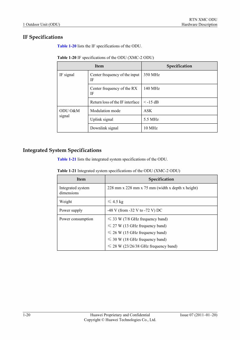
IF SpecificationsTable 1-20 lists the IF specifications of the ODU.
Table 1-20 IF specifications of the ODU (XMC-2 ODU)
Item Specification
IF signal Center frequency of the inputIF
350 MHz
Center frequency of the RXIF
140 MHz
Return loss of the IF interface < -15 dB
ODU O&Msignal
Modulation mode ASK
Uplink signal 5.5 MHz
Downlink signal 10 MHz
Integrated System SpecificationsTable 1-21 lists the integrated system specifications of the ODU.
Table 1-21 Integrated system specifications of the ODU (XMC-2 ODU)
Item Specification
Integrated systemdimensions
228 mm x 228 mm x 75 mm (width x depth x height)
Weight ≤ 4.5 kg
Power supply -48 V (from -32 V to -72 V) DC
Power consumption ≤ 33 W (7/8 GHz frequency band)≤ 27 W (13 GHz frequency band)≤ 26 W (15 GHz frequency band)≤ 30 W (18 GHz frequency band)≤ 28 W (23/26/38 GHz frequency band)
1 Outdoor Unit (ODU)RTN XMC ODU
Hardware Description
1-20 Huawei Proprietary and ConfidentialCopyright © Huawei Technologies Co., Ltd.
Issue 07 (2011–01–20)
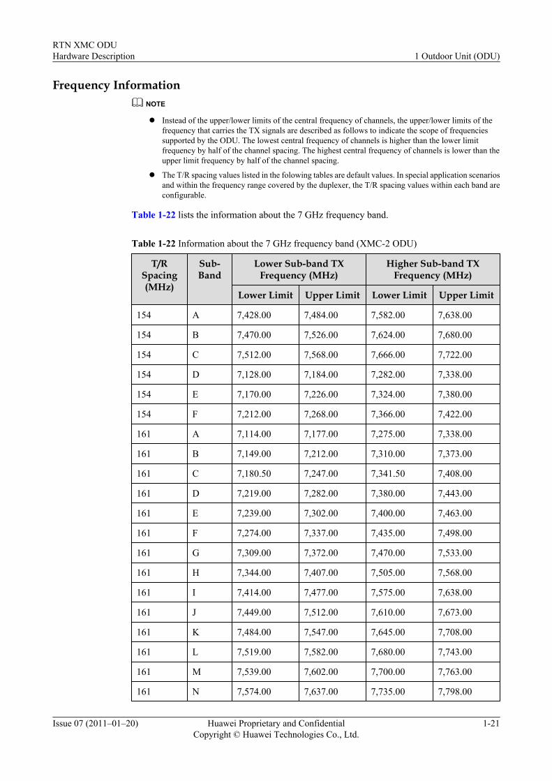
Frequency InformationNOTE
l Instead of the upper/lower limits of the central frequency of channels, the upper/lower limits of thefrequency that carries the TX signals are described as follows to indicate the scope of frequenciessupported by the ODU. The lowest central frequency of channels is higher than the lower limitfrequency by half of the channel spacing. The highest central frequency of channels is lower than theupper limit frequency by half of the channel spacing.
l The T/R spacing values listed in the folowing tables are default values. In special application scenariosand within the frequency range covered by the duplexer, the T/R spacing values within each band areconfigurable.
Table 1-22 lists the information about the 7 GHz frequency band.
Table 1-22 Information about the 7 GHz frequency band (XMC-2 ODU)
T/RSpacing(MHz)
Sub-Band
Lower Sub-band TXFrequency (MHz)
Higher Sub-band TXFrequency (MHz)
Lower Limit Upper Limit Lower Limit Upper Limit
154 A 7,428.00 7,484.00 7,582.00 7,638.00
154 B 7,470.00 7,526.00 7,624.00 7,680.00
154 C 7,512.00 7,568.00 7,666.00 7,722.00
154 D 7,128.00 7,184.00 7,282.00 7,338.00
154 E 7,170.00 7,226.00 7,324.00 7,380.00
154 F 7,212.00 7,268.00 7,366.00 7,422.00
161 A 7,114.00 7,177.00 7,275.00 7,338.00
161 B 7,149.00 7,212.00 7,310.00 7,373.00
161 C 7,180.50 7,247.00 7,341.50 7,408.00
161 D 7,219.00 7,282.00 7,380.00 7,443.00
161 E 7,239.00 7,302.00 7,400.00 7,463.00
161 F 7,274.00 7,337.00 7,435.00 7,498.00
161 G 7,309.00 7,372.00 7,470.00 7,533.00
161 H 7,344.00 7,407.00 7,505.00 7,568.00
161 I 7,414.00 7,477.00 7,575.00 7,638.00
161 J 7,449.00 7,512.00 7,610.00 7,673.00
161 K 7,484.00 7,547.00 7,645.00 7,708.00
161 L 7,519.00 7,582.00 7,680.00 7,743.00
161 M 7,539.00 7,602.00 7,700.00 7,763.00
161 N 7,574.00 7,637.00 7,735.00 7,798.00
RTN XMC ODUHardware Description 1 Outdoor Unit (ODU)
Issue 07 (2011–01–20) Huawei Proprietary and ConfidentialCopyright © Huawei Technologies Co., Ltd.
1-21
T/RSpacing(MHz)
Sub-Band
Lower Sub-band TXFrequency (MHz)
Higher Sub-band TXFrequency (MHz)
Lower Limit Upper Limit Lower Limit Upper Limit
161 O 7,609.00 7,672.00 7,770.00 7,833.00
161 P 7,644.00 7,707.00 7,805.00 7,868.00
168 A 7,443.00 7,499.00 7,611.00 7,667.00
168 B 7,485.00 7,541.00 7,653.00 7,709.00
168 C 7,527.00 7,583.00 7,695.00 7,751.00
168 D 7,110.50 7,170.00 7,278.50 7,338.00
168 E 7,163.00 7,205.00 7,331.00 7,373.00
168 F 7,198.00 7,236.50 7,366.00 7,404.50
168 G 7,226.00 7,261.00 7,394.00 7,429.00
196 A 7,093.00 7,177.00 7,289.00 7,373.00
196 B 7,149.00 7,233.00 7,345.00 7,429.00
196 C 7,205.00 7,261.00 7,401.00 7,457.00
245 A 7,400.00 7,484.00 7,645.00 7,729.00
245 B 7,484.00 7,568.00 7,729.00 7,813.00
245 C 7,568.00 7,652.00 7,813.00 7,897.00
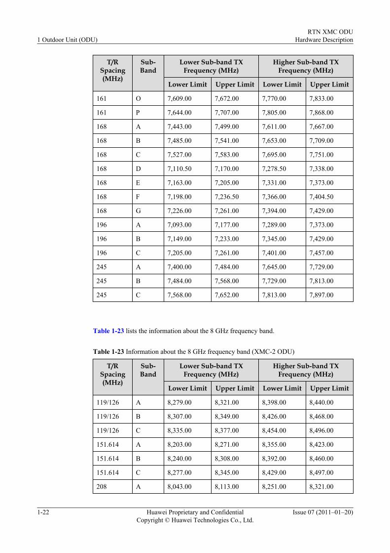
Table 1-23 lists the information about the 8 GHz frequency band.
Table 1-23 Information about the 8 GHz frequency band (XMC-2 ODU)
T/RSpacing(MHz)
Sub-Band
Lower Sub-band TXFrequency (MHz)
Higher Sub-band TXFrequency (MHz)
Lower Limit Upper Limit Lower Limit Upper Limit
119/126 A 8,279.00 8,321.00 8,398.00 8,440.00
119/126 B 8,307.00 8,349.00 8,426.00 8,468.00
119/126 C 8,335.00 8,377.00 8,454.00 8,496.00
151.614 A 8,203.00 8,271.00 8,355.00 8,423.00
151.614 B 8,240.00 8,308.00 8,392.00 8,460.00
151.614 C 8,277.00 8,345.00 8,429.00 8,497.00
208 A 8,043.00 8,113.00 8,251.00 8,321.00
1 Outdoor Unit (ODU)RTN XMC ODU
Hardware Description
1-22 Huawei Proprietary and ConfidentialCopyright © Huawei Technologies Co., Ltd.
Issue 07 (2011–01–20)
T/RSpacing(MHz)
Sub-Band
Lower Sub-band TXFrequency (MHz)
Higher Sub-band TXFrequency (MHz)
Lower Limit Upper Limit Lower Limit Upper Limit
208 B 8,099.00 8,169.00 8,307.00 8,377.00
208 C 8,155.00 8,225.00 8,363.00 8,433.00
208 D 8,211.00 8,281.00 8,419.00 8,489.00
266 A 7,905.00 8,024.00 8,171.00 8,290.00
266 B 8,017.00 8,136.00 8,283.00 8,402.00
311.32 A 7,731.00 7,867.00 8,042.00 8,178.00
311.32 B 7,835.00 7,971.00 8,146.00 8,282.00
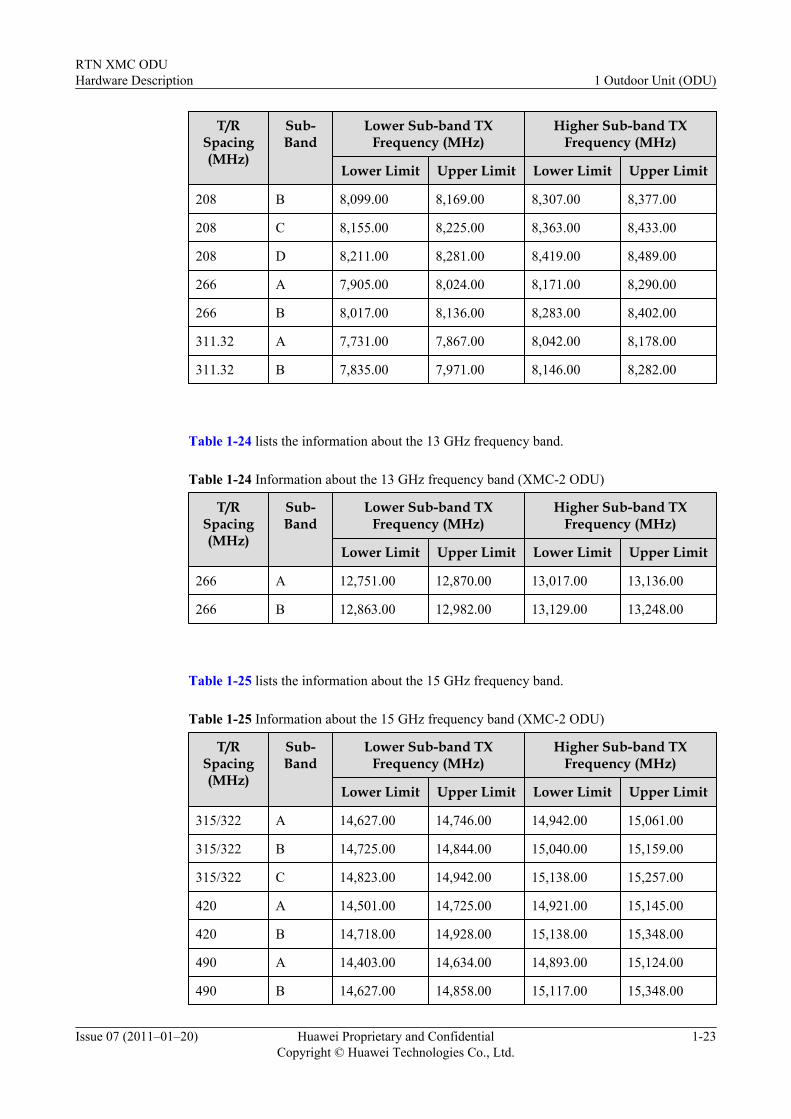
Table 1-24 lists the information about the 13 GHz frequency band.
Table 1-24 Information about the 13 GHz frequency band (XMC-2 ODU)
T/RSpacing(MHz)
Sub-Band
Lower Sub-band TXFrequency (MHz)
Higher Sub-band TXFrequency (MHz)
Lower Limit Upper Limit Lower Limit Upper Limit
266 A 12,751.00 12,870.00 13,017.00 13,136.00
266 B 12,863.00 12,982.00 13,129.00 13,248.00
Table 1-25 lists the information about the 15 GHz frequency band.
Table 1-25 Information about the 15 GHz frequency band (XMC-2 ODU)
T/RSpacing(MHz)
Sub-Band
Lower Sub-band TXFrequency (MHz)
Higher Sub-band TXFrequency (MHz)
Lower Limit Upper Limit Lower Limit Upper Limit
315/322 A 14,627.00 14,746.00 14,942.00 15,061.00
315/322 B 14,725.00 14,844.00 15,040.00 15,159.00
315/322 C 14,823.00 14,942.00 15,138.00 15,257.00
420 A 14,501.00 14,725.00 14,921.00 15,145.00
420 B 14,718.00 14,928.00 15,138.00 15,348.00
490 A 14,403.00 14,634.00 14,893.00 15,124.00
490 B 14,627.00 14,858.00 15,117.00 15,348.00
RTN XMC ODUHardware Description 1 Outdoor Unit (ODU)
Issue 07 (2011–01–20) Huawei Proprietary and ConfidentialCopyright © Huawei Technologies Co., Ltd.
1-23
T/RSpacing(MHz)
Sub-Band
Lower Sub-band TXFrequency (MHz)
Higher Sub-band TXFrequency (MHz)
Lower Limit Upper Limit Lower Limit Upper Limit
644 A 14,400.00 14,708.00 15,044.00 15,352.00
728 A 14,500.00 14,625.00 15,228.00 15,353.00
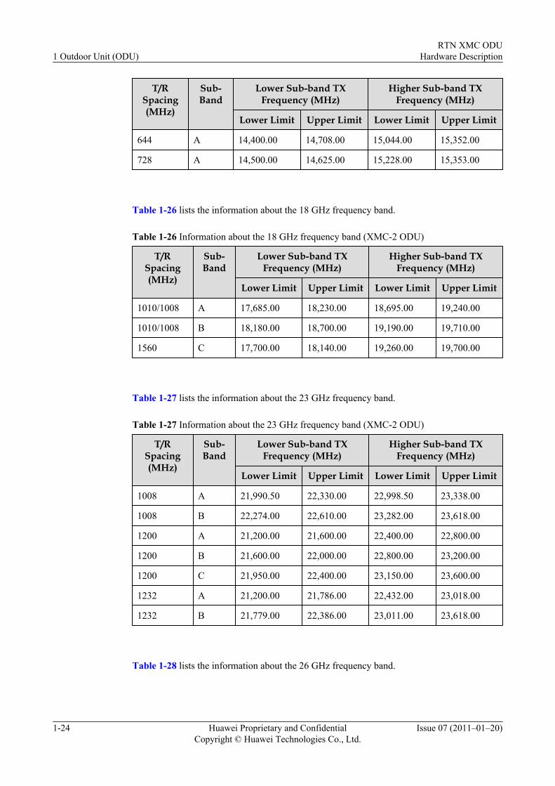
Table 1-26 lists the information about the 18 GHz frequency band.
Table 1-26 Information about the 18 GHz frequency band (XMC-2 ODU)
T/RSpacing(MHz)
Sub-Band
Lower Sub-band TXFrequency (MHz)
Higher Sub-band TXFrequency (MHz)
Lower Limit Upper Limit Lower Limit Upper Limit
1010/1008 A 17,685.00 18,230.00 18,695.00 19,240.00
1010/1008 B 18,180.00 18,700.00 19,190.00 19,710.00
1560 C 17,700.00 18,140.00 19,260.00 19,700.00
Table 1-27 lists the information about the 23 GHz frequency band.
Table 1-27 Information about the 23 GHz frequency band (XMC-2 ODU)
T/RSpacing(MHz)
Sub-Band
Lower Sub-band TXFrequency (MHz)
Higher Sub-band TXFrequency (MHz)
Lower Limit Upper Limit Lower Limit Upper Limit
1008 A 21,990.50 22,330.00 22,998.50 23,338.00
1008 B 22,274.00 22,610.00 23,282.00 23,618.00
1200 A 21,200.00 21,600.00 22,400.00 22,800.00
1200 B 21,600.00 22,000.00 22,800.00 23,200.00
1200 C 21,950.00 22,400.00 23,150.00 23,600.00
1232 A 21,200.00 21,786.00 22,432.00 23,018.00
1232 B 21,779.00 22,386.00 23,011.00 23,618.00
Table 1-28 lists the information about the 26 GHz frequency band.
1 Outdoor Unit (ODU)RTN XMC ODU
Hardware Description
1-24 Huawei Proprietary and ConfidentialCopyright © Huawei Technologies Co., Ltd.
Issue 07 (2011–01–20)
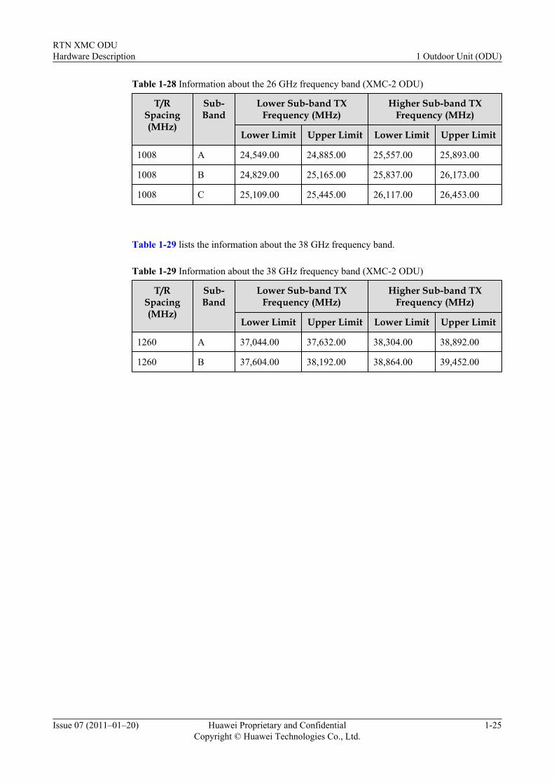
Table 1-28 Information about the 26 GHz frequency band (XMC-2 ODU)
T/RSpacing(MHz)
Sub-Band
Lower Sub-band TXFrequency (MHz)
Higher Sub-band TXFrequency (MHz)
Lower Limit Upper Limit Lower Limit Upper Limit
1008 A 24,549.00 24,885.00 25,557.00 25,893.00
1008 B 24,829.00 25,165.00 25,837.00 26,173.00
1008 C 25,109.00 25,445.00 26,117.00 26,453.00
Table 1-29 lists the information about the 38 GHz frequency band.
Table 1-29 Information about the 38 GHz frequency band (XMC-2 ODU)
T/RSpacing(MHz)
Sub-Band
Lower Sub-band TXFrequency (MHz)
Higher Sub-band TXFrequency (MHz)
Lower Limit Upper Limit Lower Limit Upper Limit
1260 A 37,044.00 37,632.00 38,304.00 38,892.00
1260 B 37,604.00 38,192.00 38,864.00 39,452.00
RTN XMC ODUHardware Description 1 Outdoor Unit (ODU)
Issue 07 (2011–01–20) Huawei Proprietary and ConfidentialCopyright © Huawei Technologies Co., Ltd.
1-25

2 Hybrid coupler
About This Chapter
This describes the hybrid coupler. Hybrid coupler is short for the RF signal combiner/divider.It is used to install two ODUs on one antenna. The hybrid couplers that are described in thisdocument are the hybrid couplers adaptive to the RTN XMC ODUs.
2.1 Device TypeThis describes the device type. The hybrid couplers is available in two series: 3 dB balancedhybrid coupler and 6 dB unbalanced hybrid coupler.
2.2 AppearanceThis describes the appearance of the hybrid coupler. The hybrid coupler is an outdoor three-interface network component of the wireless transmission products.
2.3 FunctionsThis describes the functions of the hybrid coupler. The hybrid coupler is used to combine anddivide RF signals.
2.4 Working PrinciplesThis describes the working principles of the hybrid coupler. The hybrid coupler is mainlycomposed of waveguide cavities.
2.5 InterfacesThis describes the interfaces of the hybrid coupler. The interfaces of the hybrid coupler consistof the antenna interface, main tributary interface, and extension tributary interface.
2.6 LabelThis describes the label of the hybrid coupler. The label of the hybrid coupler is attached to thehybrid coupler and packing case to identify the basic information of the hybrid coupler.
2.7 Technical SpecificationsThis describes the technical specifications of the hybrid coupler. The technical specifications ofthe hybrid coupler consist of the electrical specifications and mechanical specifications.
RTN XMC ODUHardware Description 2 Hybrid coupler
Issue 07 (2011–01–20) Huawei Proprietary and ConfidentialCopyright © Huawei Technologies Co., Ltd.
2-1
2.1 Device TypeThis describes the device type. The hybrid couplers is available in two series: 3 dB balancedhybrid coupler and 6 dB unbalanced hybrid coupler.
The features of the two series of hybrid couplers are as follows:
l The 3 dB balanced hybrid coupler divides one route of RF signals into two routes of RFsignals of the similar power. Compared with the original signal, the power attenuation ofeach tributary signal is about 3 dB.
l The 6 dB unbalanced hybrid coupler divides one route of RF signals into two routes of RFsignals of different power. Compared with the original signal, the power attenuation of thelower tributary signal is about 6 dB, and the power of the higher tributary signal decreasesabout 2 dB.
2.2 AppearanceThis describes the appearance of the hybrid coupler. The hybrid coupler is an outdoor three-interface network component of the wireless transmission products.
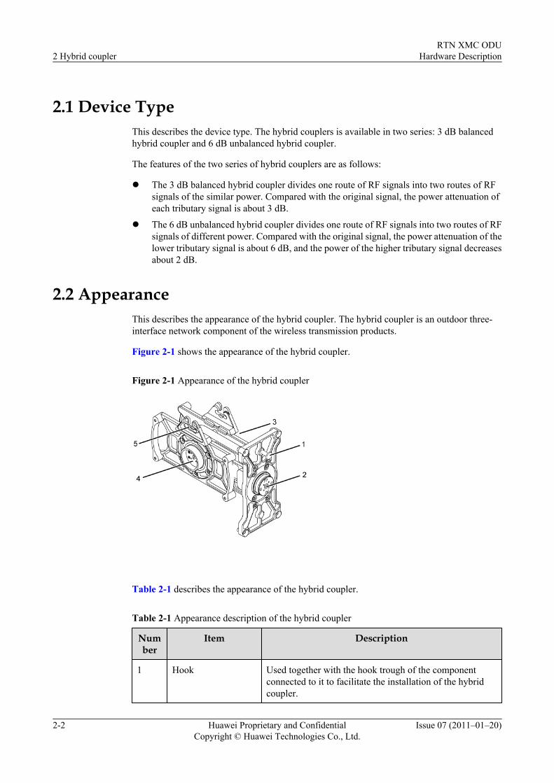
Figure 2-1 shows the appearance of the hybrid coupler.
Figure 2-1 Appearance of the hybrid coupler
Table 2-1 describes the appearance of the hybrid coupler.
Table 2-1 Appearance description of the hybrid coupler
Number
Item Description
1 Hook Used together with the hook trough of the componentconnected to it to facilitate the installation of the hybridcoupler.
2 Hybrid couplerRTN XMC ODU
Hardware Description
2-2 Huawei Proprietary and ConfidentialCopyright © Huawei Technologies Co., Ltd.
Issue 07 (2011–01–20)
Number
Item Description
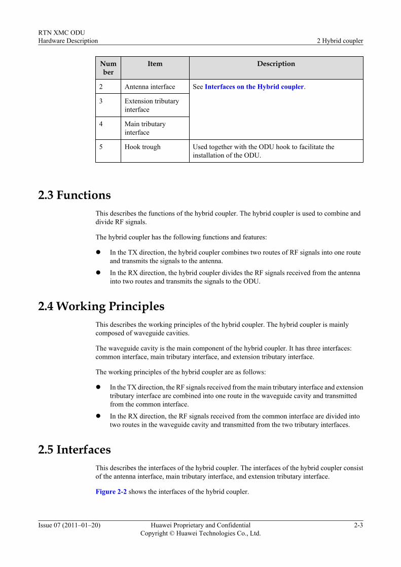
2 Antenna interface See Interfaces on the Hybrid coupler.
3 Extension tributaryinterface
4 Main tributaryinterface
5 Hook trough Used together with the ODU hook to facilitate theinstallation of the ODU.
2.3 FunctionsThis describes the functions of the hybrid coupler. The hybrid coupler is used to combine anddivide RF signals.
The hybrid coupler has the following functions and features:
l In the TX direction, the hybrid coupler combines two routes of RF signals into one routeand transmits the signals to the antenna.
l In the RX direction, the hybrid coupler divides the RF signals received from the antennainto two routes and transmits the signals to the ODU.
2.4 Working PrinciplesThis describes the working principles of the hybrid coupler. The hybrid coupler is mainlycomposed of waveguide cavities.
The waveguide cavity is the main component of the hybrid coupler. It has three interfaces:common interface, main tributary interface, and extension tributary interface.
The working principles of the hybrid coupler are as follows:
l In the TX direction, the RF signals received from the main tributary interface and extensiontributary interface are combined into one route in the waveguide cavity and transmittedfrom the common interface.
l In the RX direction, the RF signals received from the common interface are divided intotwo routes in the waveguide cavity and transmitted from the two tributary interfaces.
2.5 InterfacesThis describes the interfaces of the hybrid coupler. The interfaces of the hybrid coupler consistof the antenna interface, main tributary interface, and extension tributary interface.
Figure 2-2 shows the interfaces of the hybrid coupler.
RTN XMC ODUHardware Description 2 Hybrid coupler
Issue 07 (2011–01–20) Huawei Proprietary and ConfidentialCopyright © Huawei Technologies Co., Ltd.
2-3
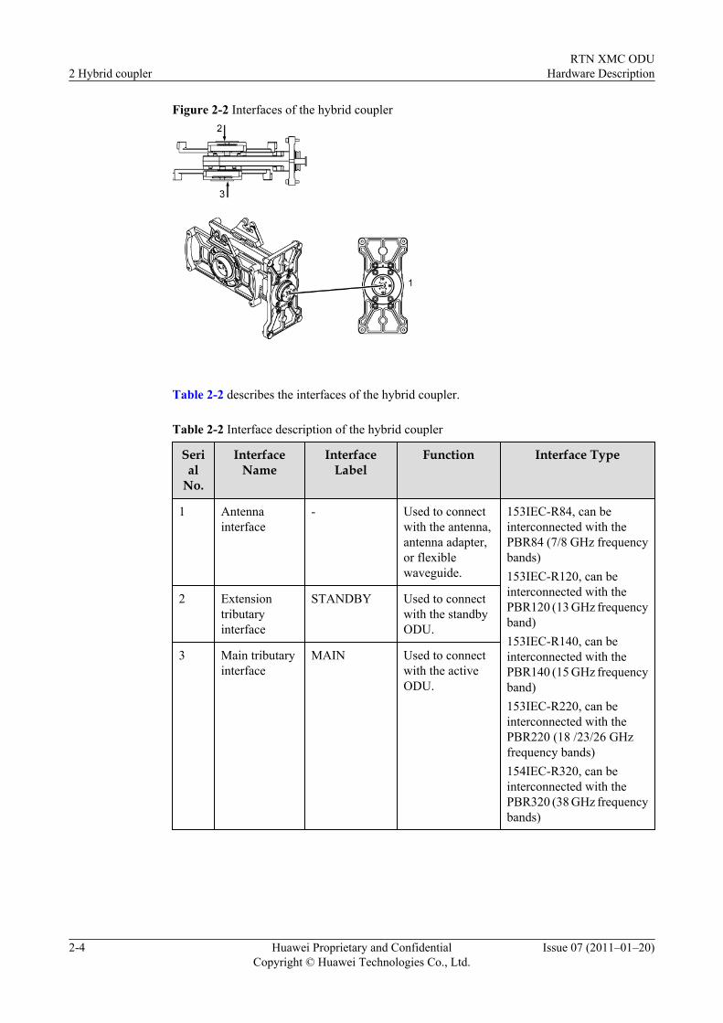
Figure 2-2 Interfaces of the hybrid coupler
Table 2-2 describes the interfaces of the hybrid coupler.
Table 2-2 Interface description of the hybrid coupler
Serial
No.
InterfaceName
InterfaceLabel
Function Interface Type
1 Antennainterface
- Used to connectwith the antenna,antenna adapter,or flexiblewaveguide.
153IEC-R84, can beinterconnected with thePBR84 (7/8 GHz frequencybands)153IEC-R120, can beinterconnected with thePBR120 (13 GHz frequencyband)153IEC-R140, can beinterconnected with thePBR140 (15 GHz frequencyband)153IEC-R220, can beinterconnected with thePBR220 (18 /23/26 GHzfrequency bands)154IEC-R320, can beinterconnected with thePBR320 (38 GHz frequencybands)
2 Extensiontributaryinterface
STANDBY Used to connectwith the standbyODU.
3 Main tributaryinterface
MAIN Used to connectwith the activeODU.
2 Hybrid couplerRTN XMC ODU
Hardware Description
2-4 Huawei Proprietary and ConfidentialCopyright © Huawei Technologies Co., Ltd.
Issue 07 (2011–01–20)
2.6 LabelThis describes the label of the hybrid coupler. The label of the hybrid coupler is attached to thehybrid coupler and packing case to identify the basic information of the hybrid coupler.
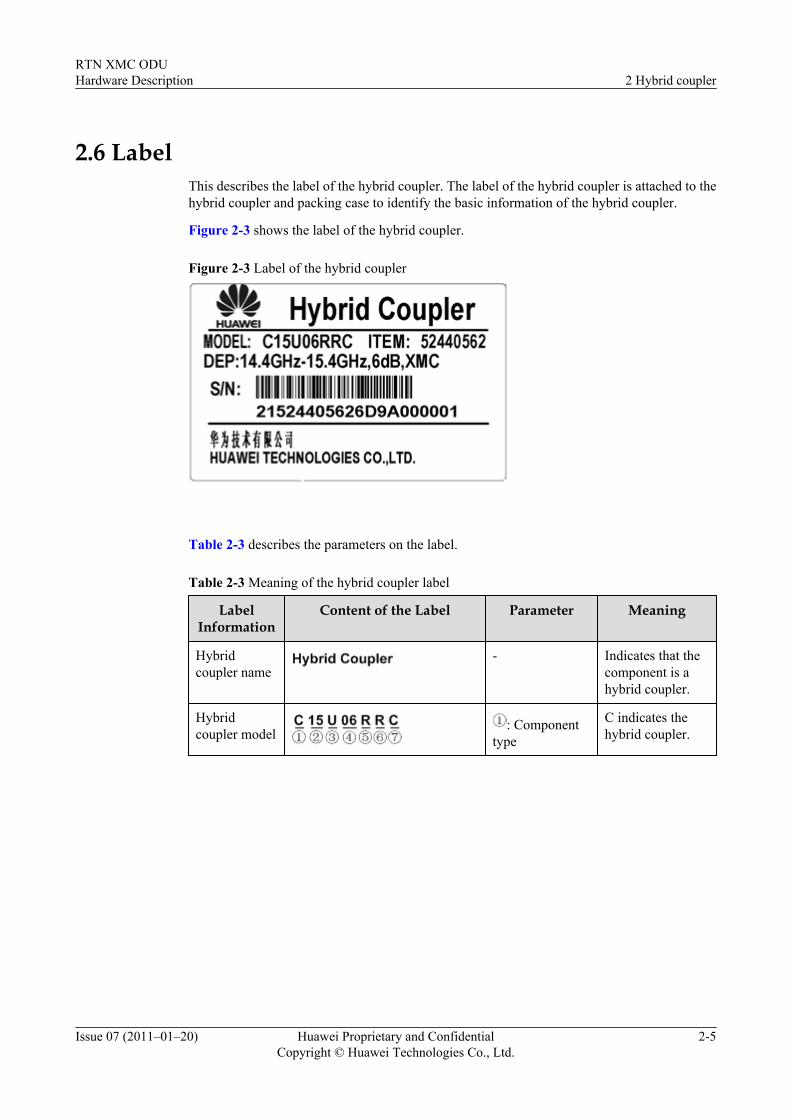
Figure 2-3 shows the label of the hybrid coupler.
Figure 2-3 Label of the hybrid coupler
Table 2-3 describes the parameters on the label.
Table 2-3 Meaning of the hybrid coupler label
LabelInformation
Content of the Label Parameter Meaning
Hybridcoupler name
- Indicates that thecomponent is ahybrid coupler.
Hybridcoupler model
: Componenttype
C indicates thehybrid coupler.
RTN XMC ODUHardware Description 2 Hybrid coupler
Issue 07 (2011–01–20) Huawei Proprietary and ConfidentialCopyright © Huawei Technologies Co., Ltd.
2-5
LabelInformation
Content of the Label Parameter Meaning
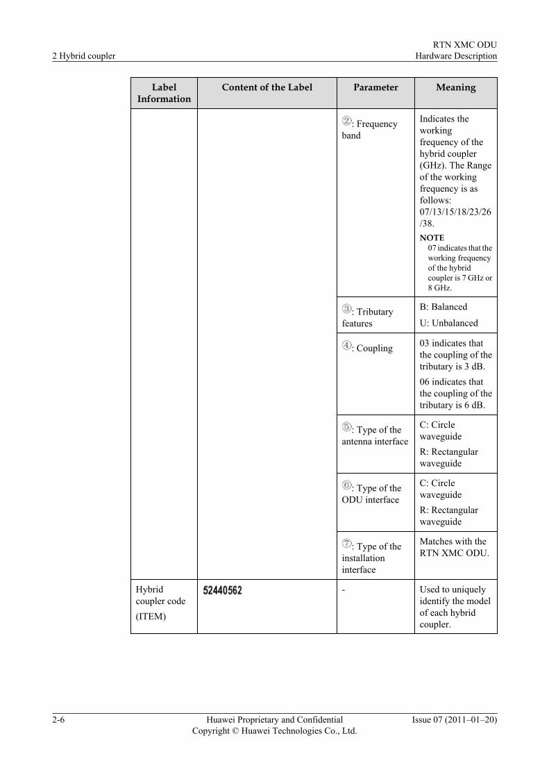
: Frequencyband
Indicates theworkingfrequency of thehybrid coupler(GHz). The Rangeof the workingfrequency is asfollows:07/13/15/18/23/26/38.NOTE
07 indicates that theworking frequencyof the hybridcoupler is 7 GHz or8 GHz.
: Tributaryfeatures
B: Balanced
U: Unbalanced
: Coupling 03 indicates thatthe coupling of thetributary is 3 dB.06 indicates thatthe coupling of thetributary is 6 dB.
: Type of theantenna interface
C: CirclewaveguideR: Rectangularwaveguide
: Type of theODU interface
C: CirclewaveguideR: Rectangularwaveguide
: Type of theinstallationinterface
Matches with theRTN XMC ODU.
Hybridcoupler code(ITEM)
- Used to uniquelyidentify the modelof each hybridcoupler.
2 Hybrid couplerRTN XMC ODU
Hardware Description
2-6 Huawei Proprietary and ConfidentialCopyright © Huawei Technologies Co., Ltd.
Issue 07 (2011–01–20)
LabelInformation
Content of the Label Parameter Meaning
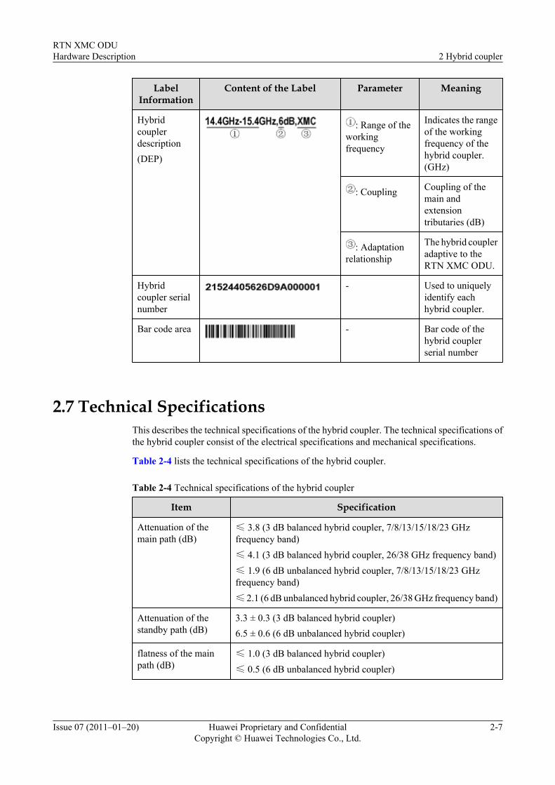
Hybridcouplerdescription(DEP)
: Range of theworkingfrequency
Indicates the rangeof the workingfrequency of thehybrid coupler.(GHz)
: Coupling Coupling of themain andextensiontributaries (dB)
: Adaptationrelationship
The hybrid coupleradaptive to theRTN XMC ODU.
Hybridcoupler serialnumber
- Used to uniquelyidentify eachhybrid coupler.
Bar code area - Bar code of thehybrid couplerserial number
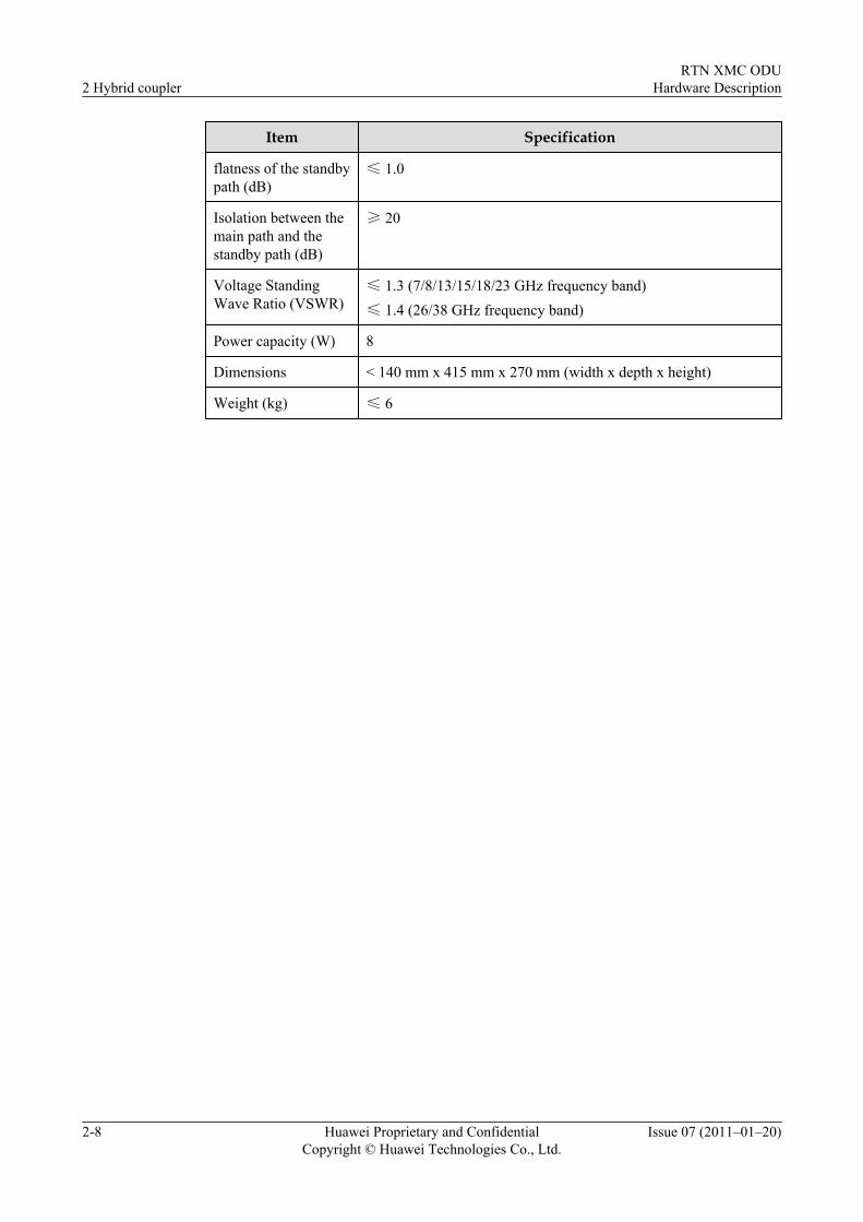
2.7 Technical SpecificationsThis describes the technical specifications of the hybrid coupler. The technical specifications ofthe hybrid coupler consist of the electrical specifications and mechanical specifications.
Table 2-4 lists the technical specifications of the hybrid coupler.
Table 2-4 Technical specifications of the hybrid coupler
Item Specification
Attenuation of themain path (dB)
≤ 3.8 (3 dB balanced hybrid coupler, 7/8/13/15/18/23 GHzfrequency band)≤ 4.1 (3 dB balanced hybrid coupler, 26/38 GHz frequency band)≤ 1.9 (6 dB unbalanced hybrid coupler, 7/8/13/15/18/23 GHzfrequency band)≤ 2.1 (6 dB unbalanced hybrid coupler, 26/38 GHz frequency band)
Attenuation of thestandby path (dB)
3.3 ± 0.3 (3 dB balanced hybrid coupler)6.5 ± 0.6 (6 dB unbalanced hybrid coupler)
flatness of the mainpath (dB)
≤ 1.0 (3 dB balanced hybrid coupler)≤ 0.5 (6 dB unbalanced hybrid coupler)
RTN XMC ODUHardware Description 2 Hybrid coupler
Issue 07 (2011–01–20) Huawei Proprietary and ConfidentialCopyright © Huawei Technologies Co., Ltd.
2-7
Item Specification
flatness of the standbypath (dB)
≤ 1.0
Isolation between themain path and thestandby path (dB)
≥ 20
Voltage StandingWave Ratio (VSWR)
≤ 1.3 (7/8/13/15/18/23 GHz frequency band)≤ 1.4 (26/38 GHz frequency band)
Power capacity (W) 8
Dimensions < 140 mm x 415 mm x 270 mm (width x depth x height)
Weight (kg) ≤ 6
2 Hybrid couplerRTN XMC ODU
Hardware Description
2-8 Huawei Proprietary and ConfidentialCopyright © Huawei Technologies Co., Ltd.
Issue 07 (2011–01–20)
3 Separate Mounting Components
About This Chapter
This describes the separate mounting components. The separate mounting components consistof the ODU separate mounting bracket and flexible waveguide. The separate mountingcomponents described in this document are the separate mounting components adaptive to theRTN XMC ODUs.
3.1 ODU Separate Mounting BracketThis describes the ODU separate mounting bracket. When the ODU or hybrid coupler is installedwith the antenna separately, the ODU separate mounting bracket can be used to fix the ODU orhybrid coupler on the pole.
3.2 Flexible WaveguideThis describes the flexible waveguide. A flexible waveguide is in rectangular form. It is used toconnect the flange interface of the ODU or hybrid coupler with the flange interface of theantenna.
RTN XMC ODUHardware Description 3 Separate Mounting Components
Issue 07 (2011–01–20) Huawei Proprietary and ConfidentialCopyright © Huawei Technologies Co., Ltd.
3-1
3.1 ODU Separate Mounting BracketThis describes the ODU separate mounting bracket. When the ODU or hybrid coupler is installedwith the antenna separately, the ODU separate mounting bracket can be used to fix the ODU orhybrid coupler on the pole.
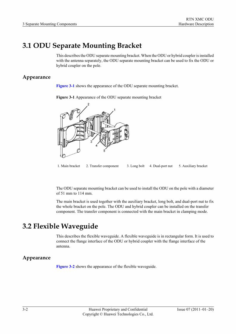
AppearanceFigure 3-1 shows the appearance of the ODU separate mounting bracket.
Figure 3-1 Appearance of the ODU separate mounting bracket
1. Main bracket 2. Transfer component 3. Long bolt 4. Dual-port nut 5. Auxiliary bracket
The ODU separate mounting bracket can be used to install the ODU on the pole with a diameterof 51 mm to 114 mm.
The main bracket is used together with the auxiliary bracket, long bolt, and dual-port nut to fixthe whole bracket on the pole. The ODU and hybrid coupler can be installed on the transfercomponent. The transfer component is connected with the main bracket in clamping mode.
3.2 Flexible WaveguideThis describes the flexible waveguide. A flexible waveguide is in rectangular form. It is used toconnect the flange interface of the ODU or hybrid coupler with the flange interface of theantenna.
AppearanceFigure 3-2 shows the appearance of the flexible waveguide.
3 Separate Mounting ComponentsRTN XMC ODU
Hardware Description
3-2 Huawei Proprietary and ConfidentialCopyright © Huawei Technologies Co., Ltd.
Issue 07 (2011–01–20)
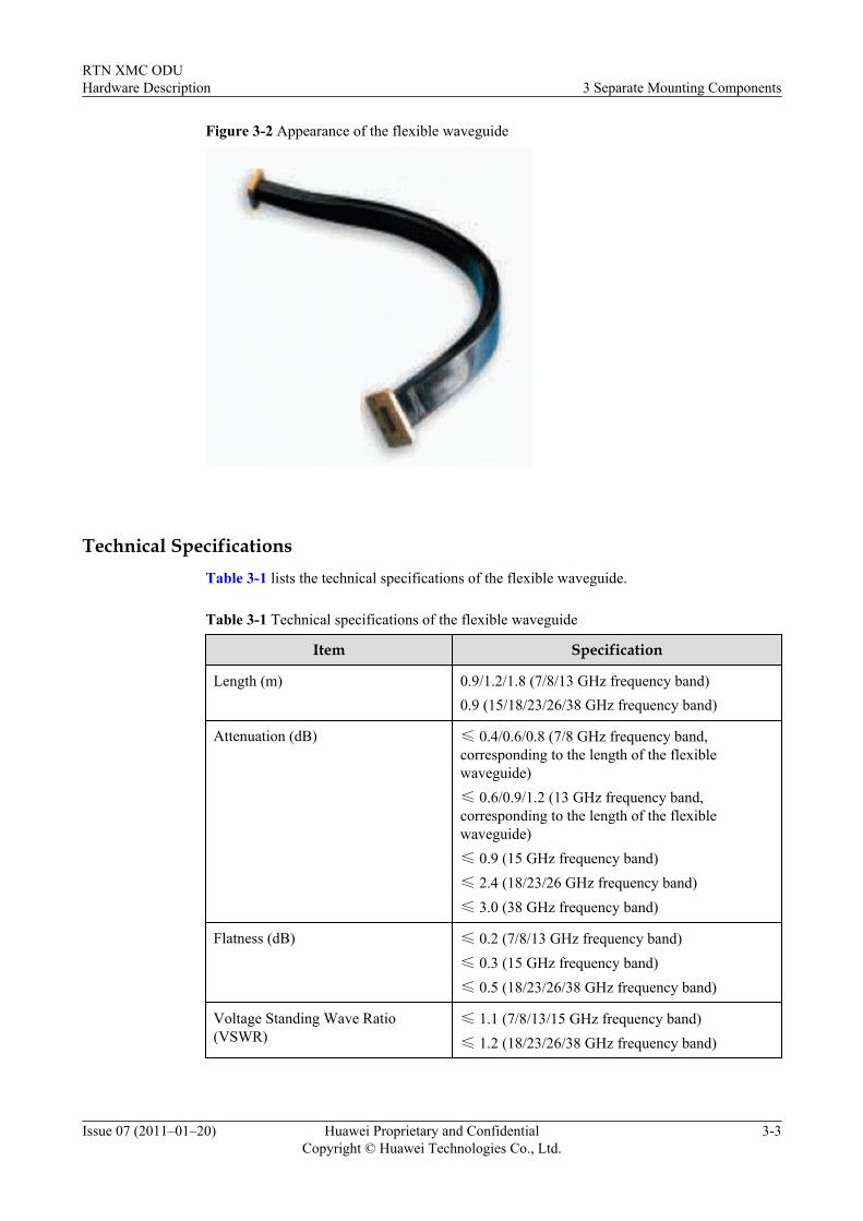
Figure 3-2 Appearance of the flexible waveguide
Technical SpecificationsTable 3-1 lists the technical specifications of the flexible waveguide.
Table 3-1 Technical specifications of the flexible waveguide
Item Specification
Length (m) 0.9/1.2/1.8 (7/8/13 GHz frequency band)0.9 (15/18/23/26/38 GHz frequency band)
Attenuation (dB) ≤ 0.4/0.6/0.8 (7/8 GHz frequency band,corresponding to the length of the flexiblewaveguide)≤ 0.6/0.9/1.2 (13 GHz frequency band,corresponding to the length of the flexiblewaveguide)≤ 0.9 (15 GHz frequency band)≤ 2.4 (18/23/26 GHz frequency band)≤ 3.0 (38 GHz frequency band)
Flatness (dB) ≤ 0.2 (7/8/13 GHz frequency band)≤ 0.3 (15 GHz frequency band)≤ 0.5 (18/23/26/38 GHz frequency band)
Voltage Standing Wave Ratio(VSWR)
≤ 1.1 (7/8/13/15 GHz frequency band)≤ 1.2 (18/23/26/38 GHz frequency band)
RTN XMC ODUHardware Description 3 Separate Mounting Components
Issue 07 (2011–01–20) Huawei Proprietary and ConfidentialCopyright © Huawei Technologies Co., Ltd.
3-3
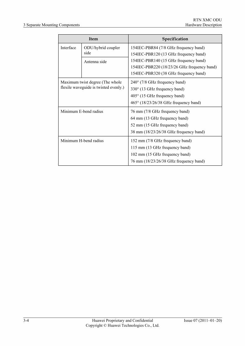
Item Specification
Interface ODU/hybrid couplerside
154IEC-PBR84 (7/8 GHz frequency band)154IEC-PBR120 (13 GHz frequency band)154IEC-PBR140 (15 GHz frequency band)154IEC-PBR220 (18/23/26 GHz frequency band)154IEC-PBR320 (38 GHz frequency band)
Antenna side
Maximum twist degree (The wholeflexile waveguide is twisted evenly.)
240° (7/8 GHz frequency band)330° (13 GHz frequency band)405° (15 GHz frequency band)465° (18/23/26/38 GHz frequency band)
Minimum E-bend radius 76 mm (7/8 GHz frequency band)64 mm (13 GHz frequency band)52 mm (15 GHz frequency band)38 mm (18/23/26/38 GHz frequency band)
Minimum H-bend radius 152 mm (7/8 GHz frequency band)115 mm (13 GHz frequency band)102 mm (15 GHz frequency band)76 mm (18/23/26/38 GHz frequency band)
3 Separate Mounting ComponentsRTN XMC ODU
Hardware Description
3-4 Huawei Proprietary and ConfidentialCopyright © Huawei Technologies Co., Ltd.
Issue 07 (2011–01–20)
4 Antennas
About This Chapter
This describes the antennas. The microwave device uses the parabolic antennas to transmit andreceive electromagnetic waves. The antennas described in this document are the parabolicantennas adaptive to the RTN XMC ODUs.
4.1 Device TypeThis describes the device types of antennas. Antennas are classified into two types, namely, thesingle-polarized antenna and dual-polarized antenna.
4.2 FunctionsThis describes the functions of the microwave antenna. The microwave antenna is used to convertbetween the RF signals transmitted from the ODU and electromagnetic waves radiated in theair.
4.3 Working PrinciplesThis describes the working principles of the antenna. The antenna consists of the reflector, feedboom, radome, shield, and mounting bracket.
4.4 InterfacesThis describes the interfaces of the antenna. The feed boom interface of the single-polarizedantenna in direct mounting mode is a waveguide interface. The feed boom interfaces of thesingle-polarized antenna in separate mounting mode and of the dual-polarized antenna are flangeinterfaces.
4.5 Antenna DiametersThis describes the antenna diameters. The antenna diameters vary according to the antenna typeand the frequency band where the antenna operates.
4.6 Technical SpecificationsThis describes the technical specifications of the antenna. The technical specifications of theantenna include the electrical indexes and mechanical indexes. The electrical indexes of theantenna include the antenna gain, half-power beamwidth, VSWR, and front-to-back ratio. Themechanical indexes of the antenna include the size, weight, wind-protective feature, and ice/snow-protective feature.
RTN XMC ODUHardware Description 4 Antennas
Issue 07 (2011–01–20) Huawei Proprietary and ConfidentialCopyright © Huawei Technologies Co., Ltd.
4-1
4.1 Device TypeThis describes the device types of antennas. Antennas are classified into two types, namely, thesingle-polarized antenna and dual-polarized antenna.
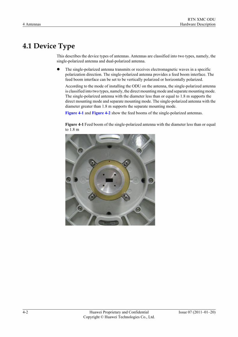
l The single-polarized antenna transmits or receives electromagnetic waves in a specificpolarization direction. The single-polarized antenna provides a feed boom interface. Thefeed boom interface can be set to be vertically polarized or horizontally polarized.According to the mode of installing the ODU on the antenna, the single-polarized antennais classified into two types, namely, the direct mounting mode and separate mounting mode.The single-polarized antenna with the diameter less than or equal to 1.8 m supports thedirect mounting mode and separate mounting mode. The single-polarized antenna with thediameter greater than 1.8 m supports the separate mounting mode.Figure 4-1 and Figure 4-2 show the feed booms of the single-polarized antennas.
Figure 4-1 Feed boom of the single-polarized antenna with the diameter less than or equalto 1.8 m
4 AntennasRTN XMC ODU
Hardware Description
4-2 Huawei Proprietary and ConfidentialCopyright © Huawei Technologies Co., Ltd.
Issue 07 (2011–01–20)
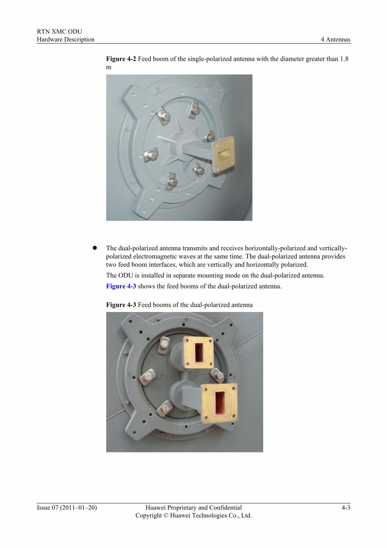
Figure 4-2 Feed boom of the single-polarized antenna with the diameter greater than 1.8m
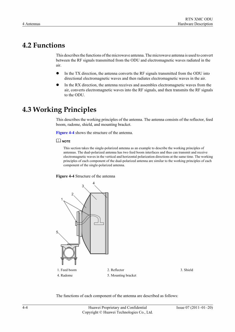
l The dual-polarized antenna transmits and receives horizontally-polarized and vertically-
polarized electromagnetic waves at the same time. The dual-polarized antenna providestwo feed boom interfaces, which are vertically and horizontally polarized.The ODU is installed in separate mounting mode on the dual-polarized antenna.Figure 4-3 shows the feed booms of the dual-polarized antenna.
Figure 4-3 Feed booms of the dual-polarized antenna
RTN XMC ODUHardware Description 4 Antennas
Issue 07 (2011–01–20) Huawei Proprietary and ConfidentialCopyright © Huawei Technologies Co., Ltd.
4-3
4.2 FunctionsThis describes the functions of the microwave antenna. The microwave antenna is used to convertbetween the RF signals transmitted from the ODU and electromagnetic waves radiated in theair.
l In the TX direction, the antenna converts the RF signals transmitted from the ODU intodirectional electromagnetic waves and then radiates electromagnetic waves in the air.
l In the RX direction, the antenna receives and assembles electromagnetic waves from theair, converts electromagnetic waves into the RF signals, and then transmits the RF signalsto the ODU.
4.3 Working PrinciplesThis describes the working principles of the antenna. The antenna consists of the reflector, feedboom, radome, shield, and mounting bracket.
Figure 4-4 shows the structure of the antenna.
NOTE
This section takes the single-polarized antenna as an example to describe the working principles ofantennas. The dual-polarized antenna has two feed boom interfaces and thus can transmit and receiveelectromagnetic waves in the vertical and horizontal polarization directions at the same time. The workingprinciples of each component of the dual-polarized antenna are similar to the working principles of eachcomponent of the single-polarized antenna.
Figure 4-4 Structure of the antenna
1. Feed boom 2. Reflector 3. Shield4. Radome 5. Mounting bracket
The functions of each component of the antenna are described as follows:
4 AntennasRTN XMC ODU
Hardware Description
4-4 Huawei Proprietary and ConfidentialCopyright © Huawei Technologies Co., Ltd.
Issue 07 (2011–01–20)
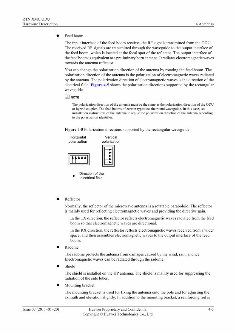
l Feed boom
The input interface of the feed boom receives the RF signals transmitted from the ODU.The received RF signals are transmitted through the waveguide to the output interface ofthe feed boom, which is located at the focal spot of the reflector. The output interface ofthe feed boom is equivalent to a preliminary horn antenna. It radiates electromagnetic wavestowards the antenna reflector.
You can change the polarization direction of the antenna by rotating the feed boom. Thepolarization direction of the antenna is the polarization of electromagnetic waves radiatedby the antenna. The polarization direction of electromagnetic waves is the direction of theelectrical field. Figure 4-5 shows the polarization directions supported by the rectangularwaveguide.
NOTE
The polarization direction of the antenna must be the same as the polarization direction of the ODUor hybrid coupler. The feed booms of certain types use the round waveguide. In this case, seeinstallation instructions of the antenna to adjust the polarization direction of the antenna accordingto the polarization identifier.
Figure 4-5 Polarization directions supported by the rectangular waveguide
Horizontalpolarization
Verticalpolarization
Direction of theelectrical field
l Reflector
Normally, the reflector of the microwave antenna is a rotatable paraboloid. The reflectoris mainly used for reflecting electromagnetic waves and providing the directive gain.
– In the TX direction, the reflector reflects electromagnetic waves radiated from the feedboom so that electromagnetic waves are directional.
– In the RX direction, the reflector reflects electromagnetic waves received from a widerspace, and then assembles electromagnetic waves to the output interface of the feedboom.
l Radome
The radome protects the antenna from damages caused by the wind, rain, and ice.Electromagnetic waves can be radiated through the radome.
l Shield
The shield is installed on the HP antenna. The shield is mainly used for suppressing theradiation of the side lobes.
l Mounting bracket
The mounting bracket is used for fixing the antenna onto the pole and for adjusting theazimuth and elevation slightly. In addition to the mounting bracket, a reinforcing rod is
RTN XMC ODUHardware Description 4 Antennas
Issue 07 (2011–01–20) Huawei Proprietary and ConfidentialCopyright © Huawei Technologies Co., Ltd.
4-5
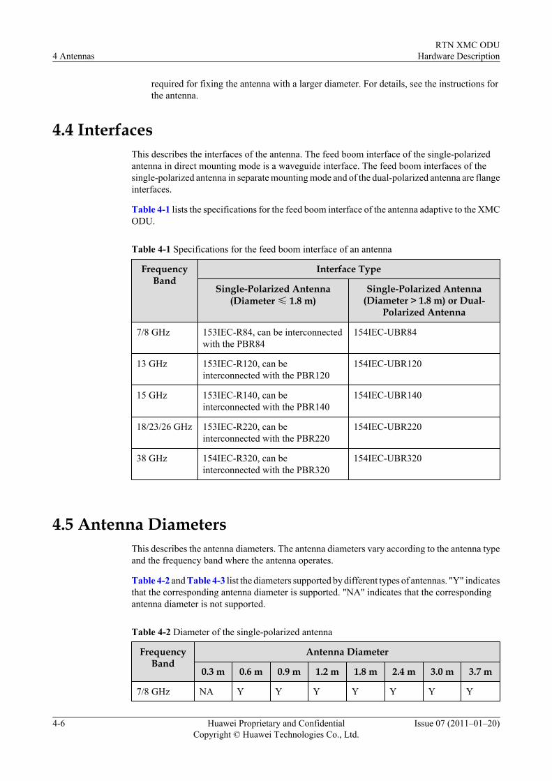
required for fixing the antenna with a larger diameter. For details, see the instructions forthe antenna.
4.4 InterfacesThis describes the interfaces of the antenna. The feed boom interface of the single-polarizedantenna in direct mounting mode is a waveguide interface. The feed boom interfaces of thesingle-polarized antenna in separate mounting mode and of the dual-polarized antenna are flangeinterfaces.
Table 4-1 lists the specifications for the feed boom interface of the antenna adaptive to the XMCODU.
Table 4-1 Specifications for the feed boom interface of an antenna
FrequencyBand
Interface Type
Single-Polarized Antenna(Diameter ≤ 1.8 m)
Single-Polarized Antenna(Diameter > 1.8 m) or Dual-
Polarized Antenna
7/8 GHz 153IEC-R84, can be interconnectedwith the PBR84
154IEC-UBR84
13 GHz 153IEC-R120, can beinterconnected with the PBR120
154IEC-UBR120
15 GHz 153IEC-R140, can beinterconnected with the PBR140
154IEC-UBR140
18/23/26 GHz 153IEC-R220, can beinterconnected with the PBR220
154IEC-UBR220
38 GHz 154IEC-R320, can beinterconnected with the PBR320
154IEC-UBR320
4.5 Antenna DiametersThis describes the antenna diameters. The antenna diameters vary according to the antenna typeand the frequency band where the antenna operates.
Table 4-2 and Table 4-3 list the diameters supported by different types of antennas. "Y" indicatesthat the corresponding antenna diameter is supported. "NA" indicates that the correspondingantenna diameter is not supported.
Table 4-2 Diameter of the single-polarized antenna
FrequencyBand
Antenna Diameter
0.3 m 0.6 m 0.9 m 1.2 m 1.8 m 2.4 m 3.0 m 3.7 m
7/8 GHz NA Y Y Y Y Y Y Y
4 AntennasRTN XMC ODU
Hardware Description
4-6 Huawei Proprietary and ConfidentialCopyright © Huawei Technologies Co., Ltd.
Issue 07 (2011–01–20)
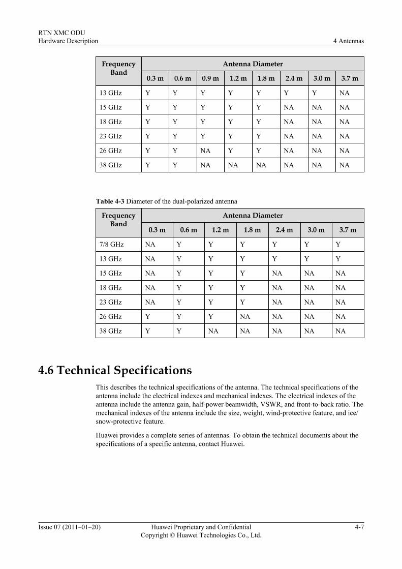
FrequencyBand
Antenna Diameter
0.3 m 0.6 m 0.9 m 1.2 m 1.8 m 2.4 m 3.0 m 3.7 m
13 GHz Y Y Y Y Y Y Y NA
15 GHz Y Y Y Y Y NA NA NA
18 GHz Y Y Y Y Y NA NA NA
23 GHz Y Y Y Y Y NA NA NA
26 GHz Y Y NA Y Y NA NA NA
38 GHz Y Y NA NA NA NA NA NA
Table 4-3 Diameter of the dual-polarized antenna
FrequencyBand
Antenna Diameter
0.3 m 0.6 m 1.2 m 1.8 m 2.4 m 3.0 m 3.7 m
7/8 GHz NA Y Y Y Y Y Y
13 GHz NA Y Y Y Y Y Y
15 GHz NA Y Y Y NA NA NA
18 GHz NA Y Y Y NA NA NA
23 GHz NA Y Y Y NA NA NA
26 GHz Y Y Y NA NA NA NA
38 GHz Y Y NA NA NA NA NA
4.6 Technical SpecificationsThis describes the technical specifications of the antenna. The technical specifications of theantenna include the electrical indexes and mechanical indexes. The electrical indexes of theantenna include the antenna gain, half-power beamwidth, VSWR, and front-to-back ratio. Themechanical indexes of the antenna include the size, weight, wind-protective feature, and ice/snow-protective feature.
Huawei provides a complete series of antennas. To obtain the technical documents about thespecifications of a specific antenna, contact Huawei.
RTN XMC ODUHardware Description 4 Antennas
Issue 07 (2011–01–20) Huawei Proprietary and ConfidentialCopyright © Huawei Technologies Co., Ltd.
4-7

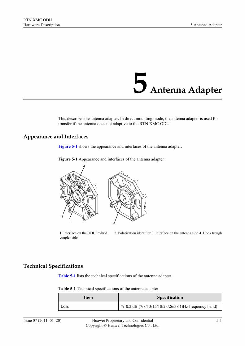
5 Antenna Adapter
This describes the antenna adapter. In direct mounting mode, the antenna adapter is used fortransfer if the antenna does not adaptive to the RTN XMC ODU.
Appearance and Interfaces
Figure 5-1 shows the appearance and interfaces of the antenna adapter.
Figure 5-1 Appearance and interfaces of the antenna adapter
1. Interface on the ODU/ hybridcoupler side
2. Polarization identifier 3. Interface on the antenna side 4. Hook trough
Technical Specifications
Table 5-1 lists the technical specifications of the antenna adapter.
Table 5-1 Technical specifications of the antenna adapter
Item Specification
Loss ≤ 0.2 dB (7/8/13/15/18/23/26/38 GHz frequency band)
RTN XMC ODUHardware Description 5 Antenna Adapter
Issue 07 (2011–01–20) Huawei Proprietary and ConfidentialCopyright © Huawei Technologies Co., Ltd.
5-1
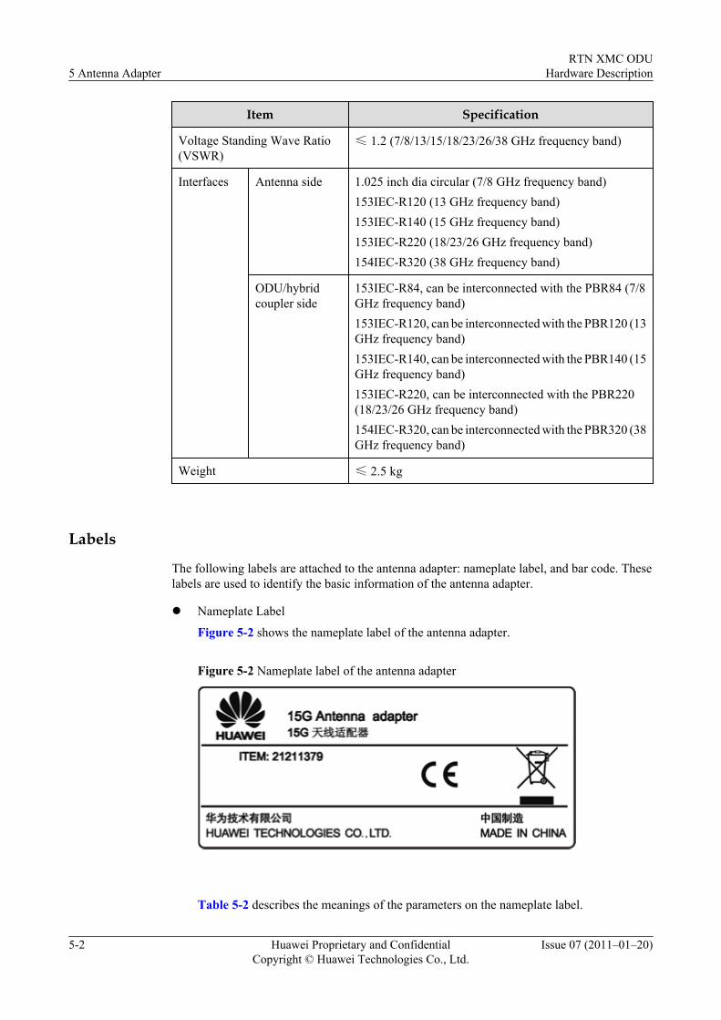
Item Specification
Voltage Standing Wave Ratio(VSWR)
≤ 1.2 (7/8/13/15/18/23/26/38 GHz frequency band)
Interfaces Antenna side 1.025 inch dia circular (7/8 GHz frequency band)153IEC-R120 (13 GHz frequency band)153IEC-R140 (15 GHz frequency band)153IEC-R220 (18/23/26 GHz frequency band)154IEC-R320 (38 GHz frequency band)
ODU/hybridcoupler side
153IEC-R84, can be interconnected with the PBR84 (7/8GHz frequency band)153IEC-R120, can be interconnected with the PBR120 (13GHz frequency band)153IEC-R140, can be interconnected with the PBR140 (15GHz frequency band)153IEC-R220, can be interconnected with the PBR220(18/23/26 GHz frequency band)154IEC-R320, can be interconnected with the PBR320 (38GHz frequency band)
Weight ≤ 2.5 kg
Labels
The following labels are attached to the antenna adapter: nameplate label, and bar code. Theselabels are used to identify the basic information of the antenna adapter.
l Nameplate Label
Figure 5-2 shows the nameplate label of the antenna adapter.
Figure 5-2 Nameplate label of the antenna adapter
Table 5-2 describes the meanings of the parameters on the nameplate label.
5 Antenna AdapterRTN XMC ODU
Hardware Description
5-2 Huawei Proprietary and ConfidentialCopyright © Huawei Technologies Co., Ltd.
Issue 07 (2011–01–20)
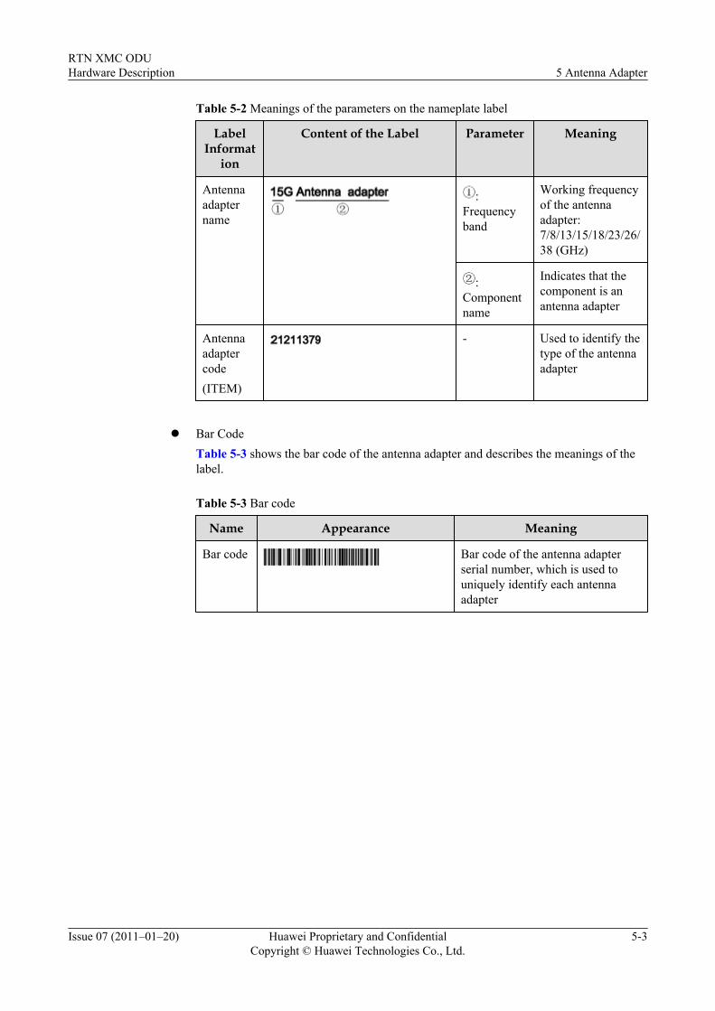
Table 5-2 Meanings of the parameters on the nameplate label
LabelInformat
ion
Content of the Label Parameter Meaning
Antennaadaptername
:Frequencyband
Working frequencyof the antennaadapter:7/8/13/15/18/23/26/38 (GHz)
:Componentname
Indicates that thecomponent is anantenna adapter
Antennaadaptercode(ITEM)
- Used to identify thetype of the antennaadapter
l Bar Code
Table 5-3 shows the bar code of the antenna adapter and describes the meanings of thelabel.
Table 5-3 Bar code
Name Appearance Meaning
Bar code Bar code of the antenna adapterserial number, which is used touniquely identify each antennaadapter
RTN XMC ODUHardware Description 5 Antenna Adapter
Issue 07 (2011–01–20) Huawei Proprietary and ConfidentialCopyright © Huawei Technologies Co., Ltd.
5-3

6 Cables
About This Chapter
This describes the cables of the ODU. The cables of the ODU which consist of the IF cable andODU PGND cable.
6.1 IF CableThis describes the IF cable. The IF cable is used to connect the ODU with the IDU and transmitsthe IF signals O&M signals and -48 V power between the ODU and the IDU.
6.2 PGND Cable of the ODUThis describes the PGND cable of the ODU. The ODU PGND cable is used to connect thegrounding screw of the ODU to the outdoor ground point such as the ground point on the towerso that the ODU can be connected to the outdoor grounding grid.
RTN XMC ODUHardware Description 6 Cables
Issue 07 (2011–01–20) Huawei Proprietary and ConfidentialCopyright © Huawei Technologies Co., Ltd.
6-1
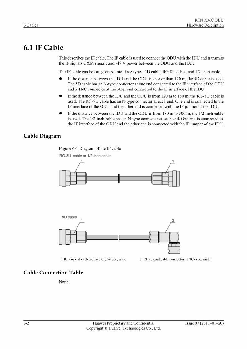
6.1 IF CableThis describes the IF cable. The IF cable is used to connect the ODU with the IDU and transmitsthe IF signals O&M signals and -48 V power between the ODU and the IDU.
The IF cable can be categorized into three types: 5D cable, RG-8U cable, and 1/2-inch cable.l If the distance between the IDU and the ODU is shorter than 120 m, the 5D cable is used.
The 5D cable has an N-type connector at one end connected to the IF interface of the ODUand a TNC connector at the other end connected to the IF interface of the IDU.
l If the distance between the IDU and the ODU is from 120 m to 180 m, the RG-8U cable isused. The RG-8U cable has an N-type connector at each end. One end is connected to theIF interface of the ODU and the other end is connected with the IF jumper of the IDU.
l If the distance between the IDU and the ODU is from 180 m to 300 m, the 1/2-inch cableis used. The 1/2-inch cable has an N-type connector at each end. One end is connected tothe IF interface of the ODU and the other end is connected with the IF jumper of the IDU.
Cable Diagram
Figure 6-1 Diagram of the IF cable
1. RF coaxial cable connector, N-type, male 2. RF coaxial cable connector, TNC-type, male
Cable Connection TableNone.
6 CablesRTN XMC ODU
Hardware Description
6-2 Huawei Proprietary and ConfidentialCopyright © Huawei Technologies Co., Ltd.
Issue 07 (2011–01–20)
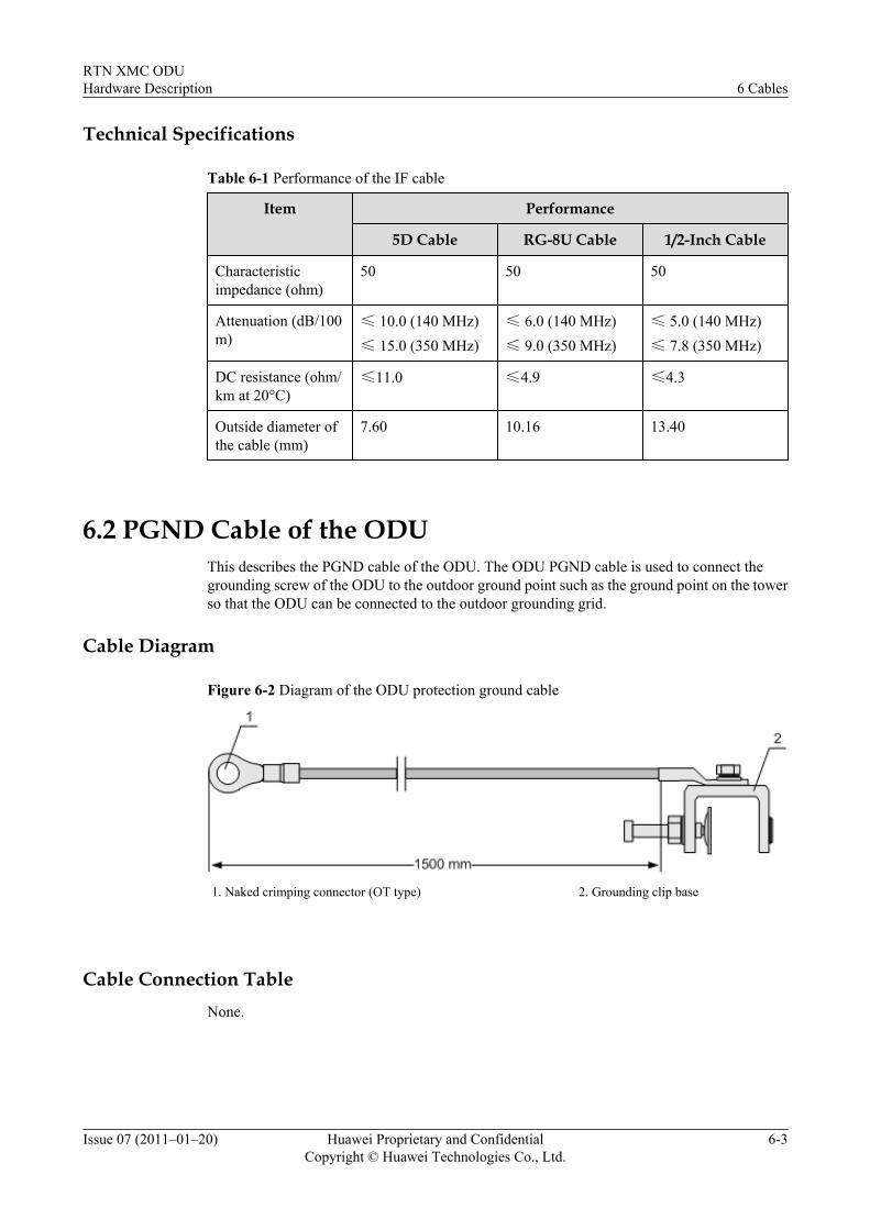
Technical Specifications
Table 6-1 Performance of the IF cable
Item Performance
5D Cable RG-8U Cable 1/2-Inch Cable
Characteristicimpedance (ohm)
50 50 50
Attenuation (dB/100m)
≤ 10.0 (140 MHz)≤ 15.0 (350 MHz)
≤ 6.0 (140 MHz)≤ 9.0 (350 MHz)
≤ 5.0 (140 MHz)≤ 7.8 (350 MHz)
DC resistance (ohm/km at 20°C)
≤11.0 ≤4.9 ≤4.3
Outside diameter ofthe cable (mm)
7.60 10.16 13.40
6.2 PGND Cable of the ODUThis describes the PGND cable of the ODU. The ODU PGND cable is used to connect thegrounding screw of the ODU to the outdoor ground point such as the ground point on the towerso that the ODU can be connected to the outdoor grounding grid.
Cable Diagram
Figure 6-2 Diagram of the ODU protection ground cable
1. Naked crimping connector (OT type) 2. Grounding clip base
Cable Connection TableNone.
RTN XMC ODUHardware Description 6 Cables
Issue 07 (2011–01–20) Huawei Proprietary and ConfidentialCopyright © Huawei Technologies Co., Ltd.
6-3
Related Documents