Exposed Linear Encoders with Singlefield Scanning MS 14 Series ELECTROMATE Toll Free Phone (877) SERVO98 Toll Free Fax (877) SERV099 www.electromate.com [email protected] Sold & Serviced By:

Rsf electronik ms14_series_catalog
Aug 17, 2015
Welcome message from author
This document is posted to help you gain knowledge. Please leave a comment to let me know what you think about it! Share it to your friends and learn new things together.
Transcript
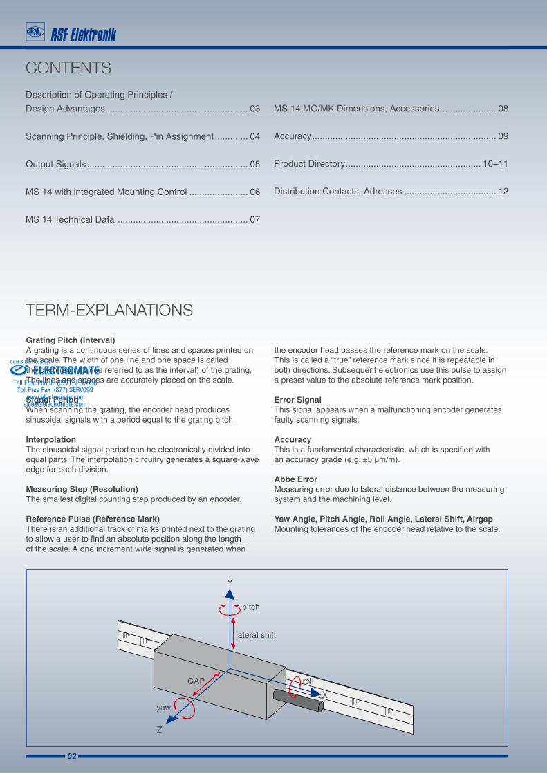
Exposed Linear Encoders with Singlefield Scanning
MS 14 Series
ELECTROMATEToll Free Phone (877) SERVO98
Toll Free Fax (877) SERV099www.electromate.com
Sold & Serviced By:
02
CONTENTSDescription of Operating Principles /
Design Advantages ....................................................... 03
Scanning Principle, Shielding, Pin Assignment ............. 04
Output Signals ............................................................... 05
MS 14 with integrated Mounting Control ....................... 06
MS 14 Technical Data ................................................... 07
Grating Pitch (Interval)A grating is a continuous series of lines and spaces printed on the scale. The width of one line and one space is called the pitch (sometimes referred to as the interval) of the grating. The lines and spaces are accurately placed on the scale.
Signal PeriodWhen scanning the grating, the encoder head produces sinusoidal signals with a period equal to the grating pitch.
InterpolationThe sinusoidal signal period can be electronically divided into equal parts. The interpolation circuitry generates a square-wave edge for each division.
Measuring Step (Resolution)The smallest digital counting step produced by an encoder.
Reference Pulse (Reference Mark)There is an additional track of marks printed next to the grating to allow a user to find an absolute position along the length of the scale. A one increment wide signal is generated when
TERM-EXPLANATIONS
the encoder head passes the reference mark on the scale. This is called a “true” reference mark since it is repeatable in both directions. Subsequent electronics use this pulse to assign a preset value to the absolute reference mark position.
Error SignalThis signal appears when a malfunctioning encoder generates faulty scanning signals.
AccuracyThis is a fundamental characteristic, which is specified with an accuracy grade (e.g. ±5 µm/m).
Abbe ErrorMeasuring error due to lateral distance between the measuring system and the machining level.
Yaw Angle, Pitch Angle, Roll Angle, Lateral Shift, AirgapMounting tolerances of the encoder head relative to the scale.
MS 14 MO/MK Dimensions, Accessories ...................... 08
Accuracy ........................................................................ 09
Product Directory ..................................................... 10–11
Distribution Contacts, Adresses .................................... 12
ELECTROMATEToll Free Phone (877) SERVO98
Toll Free Fax (877) SERV099www.electromate.com
Sold & Serviced By:
03
Contamination resistance
Immunity against aging and temperature changes
High traversing speed
Large mounting tolerances
Extremly small dimensions
The MS 14 series meets all these requirements!
The trend today in motion control applications is for exposed Linear Encoder systems.This is driven by steadily increasing demands for Higher traversing speed Higher operating cycles Lower mechanical backlash Zero frictional force induced by the encoder.Only exposed, non-contact encoders fulfill all these requirements.
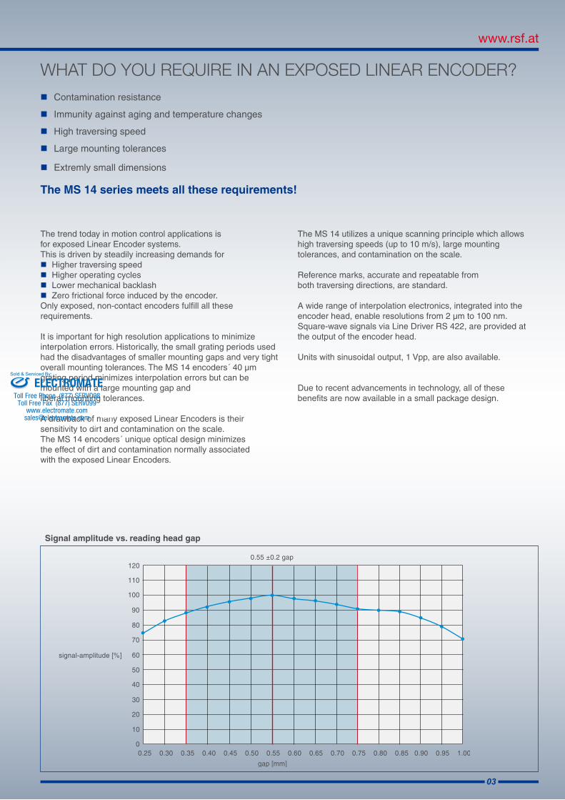
It is important for high resolution applications to minimizeinterpolation errors. Historically, the small grating periods used had the disadvantages of smaller mounting gaps and very tight overall mounting tolerances. The MS 14 encoders´ 40 µm grating period minimizes interpolation errors but can be mounted with a large mounting gap and liberal mounting tolerances.
A drawback of many exposed Linear Encoders is their sensitivity to dirt and contamination on the scale. The MS 14 encoders´ unique optical design minimizes the effect of dirt and contamination normally associated with the exposed Linear Encoders.
The MS 14 utilizes a unique scanning principle which allows high traversing speeds (up to 10 m/s), large mounting tolerances, and contamination on the scale.
Reference marks, accurate and repeatable from both traversing directions, are standard.
A wide range of interpolation electronics, integrated into the encoder head, enable resolutions from 2 µm to 100 nm.Square-wave signals via Line Driver RS 422, are provided at the output of the encoder head.
Units with sinusoidal output, 1 Vpp, are also available.
Due to recent advancements in technology, all of these benefits are now available in a small package design.
Signal amplitude vs. reading head gap
WHAT DO YOU REQUIRE IN AN EXPOSED LINEAR ENCODER?
ELECTROMATEToll Free Phone (877) SERVO98
Toll Free Fax (877) SERV099www.electromate.com
Sold & Serviced By:
04
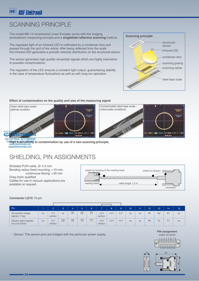
Scanning principle
PIN assignment (view on pins)
The model MS 14 incremental Linear Encoder works with the imaging, photoelectric measuring principle and a singlefield reflective scanning method. The regulated light of an infrared LED is collimated by a condenser lens and passes through the grid of the reticle. After being reflected from the scale the infrared LED generates a periodic intensity distribution on the structured sensor.
The sensor generates high qualitiy sinusoidal signals which are highly insensitive to possible contaminations.
The regulation of the LED ensures a constant light output, guaranteeing stability in the case of temperature fluctuations as well as with long-run operation.
SCANNING PRINCIPLE
Effect of contamination on the quality and size of the measuring signal
High insensitivity to contamination by use of a new scanning principle.
Shielded PUR-cable, Ø: 4.3 mmBending radius fixed mounting: > 10 mm, continuous flexing: > 20 mm Drag chain qualifiedCables for use in vacuum applications are available on request.
SHIELDING, PIN ASSIGNMENTS
Contaminated steel tape scale -unfavorable conditions
Connector LD15 15-pin
- Sensor: The sensor-pins are bridged with the particular power supply.
Pin 1 2 3 4 5 6 7 8 9 10 11 12 13 14 15
Sinusoidal voltage signals 1 Vpp
nc 0 Vsensor
nc RI A2 A1 +5 Vsensor
+5 V 0 V nc nc RI A2 A1 nc
Square-wave signals via Line Driver
nc 0 Vsensor
US RI T2 T1 +5 Vsensor
+5 V 0 V nc nc RI T2 T1 nc
Clean steel tape scale -optimal condition
ELECTROMATEToll Free Phone (877) SERVO98
Toll Free Fax (877) SERV099www.electromate.com
Sold & Serviced By:
05
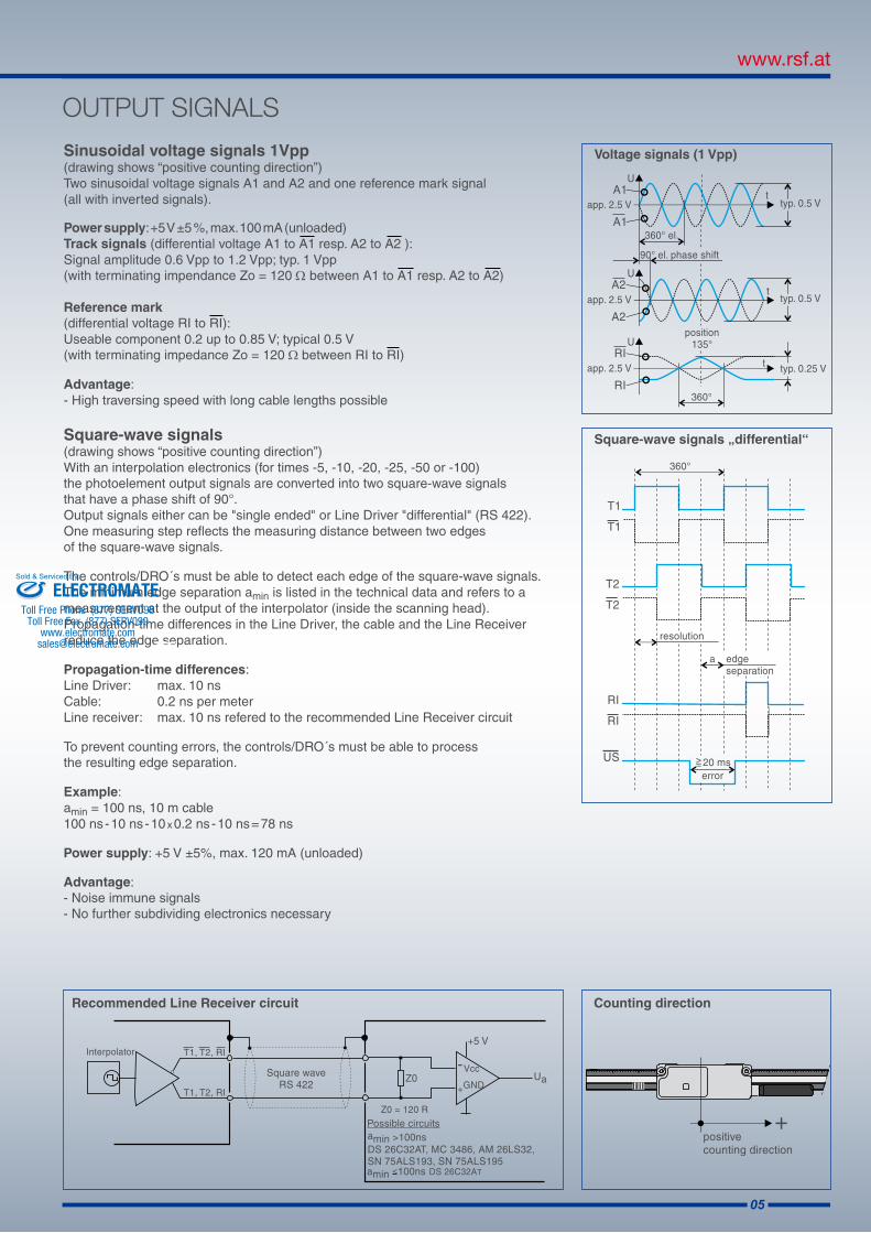
Voltage signals (1 Vpp)
Counting directionRecommended Line Receiver circuit
Square-wave signals „differential“
OUTPUT SIGNALS
Sinusoidal voltage signals 1Vpp (drawing shows “positive counting direction”)Two sinusoidal voltage signals A1 and A2 and one reference mark signal(all with inverted signals).
Power supply: +5 V ±5 %, max. 100 mA (unloaded)Track signals (differential voltage A1 to A1 resp. A2 to A2 ): Signal amplitude 0.6 Vpp to 1.2 Vpp; typ. 1 Vpp (with terminating impendance Zo = 120 Ω between A1 to A1 resp. A2 to A2)
Reference mark (differential voltage RI to RI): Useable component 0.2 up to 0.85 V; typical 0.5 V (with terminating impedance Zo = 120 Ω between RI to RI) Advantage:- High traversing speed with long cable lengths possible
Square-wave signals (drawing shows “positive counting direction”) With an interpolation electronics (for times -5, -10, -20, -25, -50 or -100) the photoelement output signals are converted into two square-wave signals that have a phase shift of 90°. Output signals either can be "single ended" or Line Driver "differential" (RS 422).One measuring step reflects the measuring distance between two edges of the square-wave signals.
The controls/DRO´s must be able to detect each edge of the square-wave signals.The minimum edge separation amin is listed in the technical data and refers to ameasurement at the output of the interpolator (inside the scanning head).Propagation-time differences in the Line Driver, the cable and the Line Receiverreduce the edge separation.
Propagation-time differences:Line Driver: max. 10 nsCable: 0.2 ns per meterLine receiver: max. 10 ns refered to the recommended Line Receiver circuit
To prevent counting errors, the controls/DRO´s must be able to process the resulting edge separation.
Example: amin = 100 ns, 10 m cable100 ns - 10 ns - 10 x 0.2 ns - 10 ns = 78 ns
Power supply: +5 V ±5%, max. 120 mA (unloaded)
Advantage:- Noise immune signals- No further subdividing electronics necessary
ELECTROMATEToll Free Phone (877) SERVO98
Toll Free Fax (877) SERV099www.electromate.com
Sold & Serviced By:
06
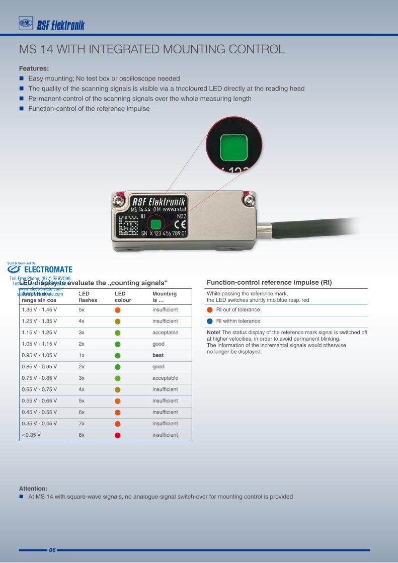
Features:
Easy mounting; No test box or oscilloscope needed
The quality of the scanning signals is visible via a tricoloured LED directly at the reading head
Permanent-control of the scanning signals over the whole measuring length
Function-control of the reference impulse
MS 14 WITH INTEGRATED MOUNTING CONTROL
LED-display to evaluate the „counting signals“
RI out of tolerance
RI within tolerance
Note! The status display of the reference mark signal is switched off at higher velocities, in order to avoid permanent blinking. The information of the incremental signals would otherwise no longer be displayed.
Function-control reference impulse (RI)
While passing the reference mark, the LED switches shortly into blue resp. red
Attention: At MS 14 with square-wave signals, no analogue-signal switch-over for mounting control is provided
Amplitude- range sin cos
LED flashes
LED colour
Mounting is …
1.35 V - 1.45 V 5x insufficient
1.25 V - 1.35 V 4x insufficient
1.15 V - 1.25 V 3x acceptable
1.05 V - 1.15 V 2x good
0.95 V - 1.05 V 1x best
0.85 V - 0.95 V 2x good
0.75 V - 0.85 V 3x acceptable
0.65 V - 0.75 V 4x insufficient
0.55 V - 0.65 V 5x insufficient
0.45 V - 0.55 V 6x insufficient
0.35 V - 0.45 V 7x insufficient
< 0.35 V 8x insufficient
ELECTROMATEToll Free Phone (877) SERVO98
Toll Free Fax (877) SERV099www.electromate.com
Sold & Serviced By:
07
MS 14 TECHNICAL DATA
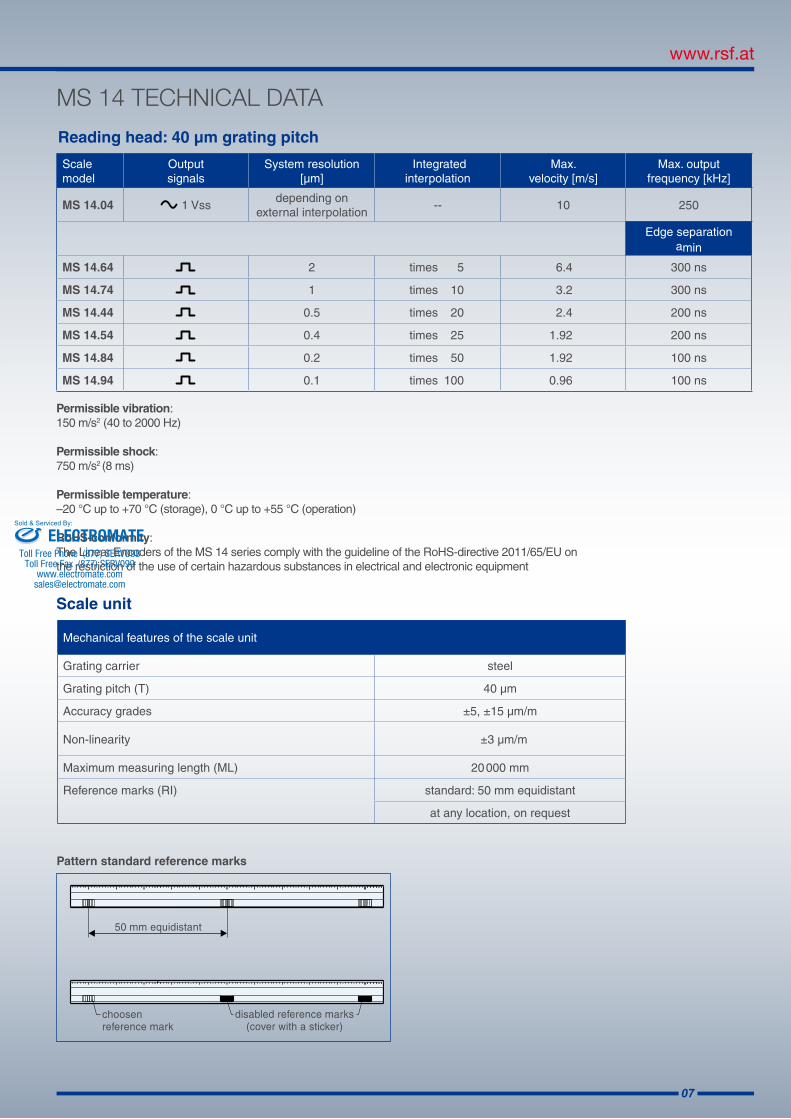
Reading head: 40 µm grating pitch
Scale unit
Permissible vibration: 150 m/s2 (40 to 2000 Hz)
Permissible shock: 750 m/s2 (8 ms)
Permissible temperature:–20 °C up to +70 °C (storage), 0 °C up to +55 °C (operation)
RoHS-conformity: The Linear Encoders of the MS 14 series comply with the guideline of the RoHS-directive 2011/65/EU onthe restriction of the use of certain hazardous substances in electrical and electronic equipment
Mechanical features of the scale unit
Grating carrier steel
Grating pitch (T) 40 µm
Accuracy grades ±5, ±15 µm/m
Non-linearity ±3 µm/m
Maximum measuring length (ML) 20 000 mm
Reference marks (RI) standard: 50 mm equidistant
at any location, on request
Scale model
Output signals
System resolution[µm]
Integrated interpolation
Max. velocity [m/s]
Max. output frequency [kHz]
MS 14.04 1 Vssdepending on
external interpolation-- 10 250
Edge separationamin
MS 14.64 2 times 5 6.4 300 ns
MS 14.74 1 times 10 3.2 300 ns
MS 14.44 0.5 times 20 2.4 200 ns
MS 14.54 0.4 times 25 1.92 200 ns
MS 14.84 0.2 times 50 1.92 100 ns
MS 14.94 0.1 times 100 0.96 100 ns
Pattern standard reference marks
ELECTROMATEToll Free Phone (877) SERVO98
Toll Free Fax (877) SERV099www.electromate.com
Sold & Serviced By:
08
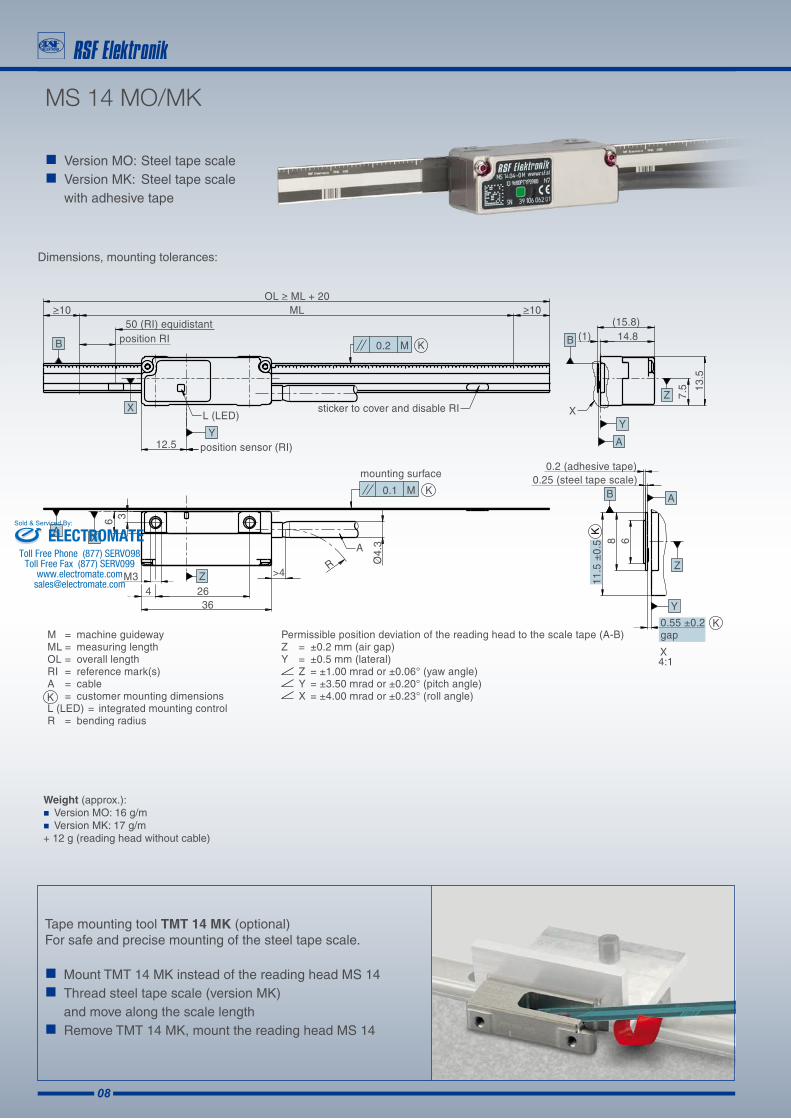
Version MO: Steel tape scale Version MK: Steel tape scale
with adhesive tape
MS 14 MO/MK
Dimensions, mounting tolerances:
Weight (approx.): Version MO: 16 g/m Version MK: 17 g/m + 12 g (reading head without cable)
Tape mounting tool TMT 14 MK (optional)For safe and precise mounting of the steel tape scale.
Mount TMT 14 MK instead of the reading head MS 14 Thread steel tape scale (version MK)
and move along the scale length Remove TMT 14 MK, mount the reading head MS 14
ELECTROMATEToll Free Phone (877) SERVO98
Toll Free Fax (877) SERV099www.electromate.com
Sold & Serviced By:

09
The accuracy of the Linear Encoder is classified with a „± tolerance“ in µm/m (e.g. ± 5 µm/m).
The accuracy refers to any meter within the measuring length.For measuring lengths less than 1000 mm, the accuracy specification applies to the whole measuring length.
For best system accuracy, the encoder should be mounted near the machining level and as parallel as possible to the motion direction.
Example of a typical calibration chart for a MS 14 scale tape:
ACCURACY
ELECTROMATEToll Free Phone (877) SERVO98
Toll Free Fax (877) SERV099www.electromate.com
Sold & Serviced By:
10
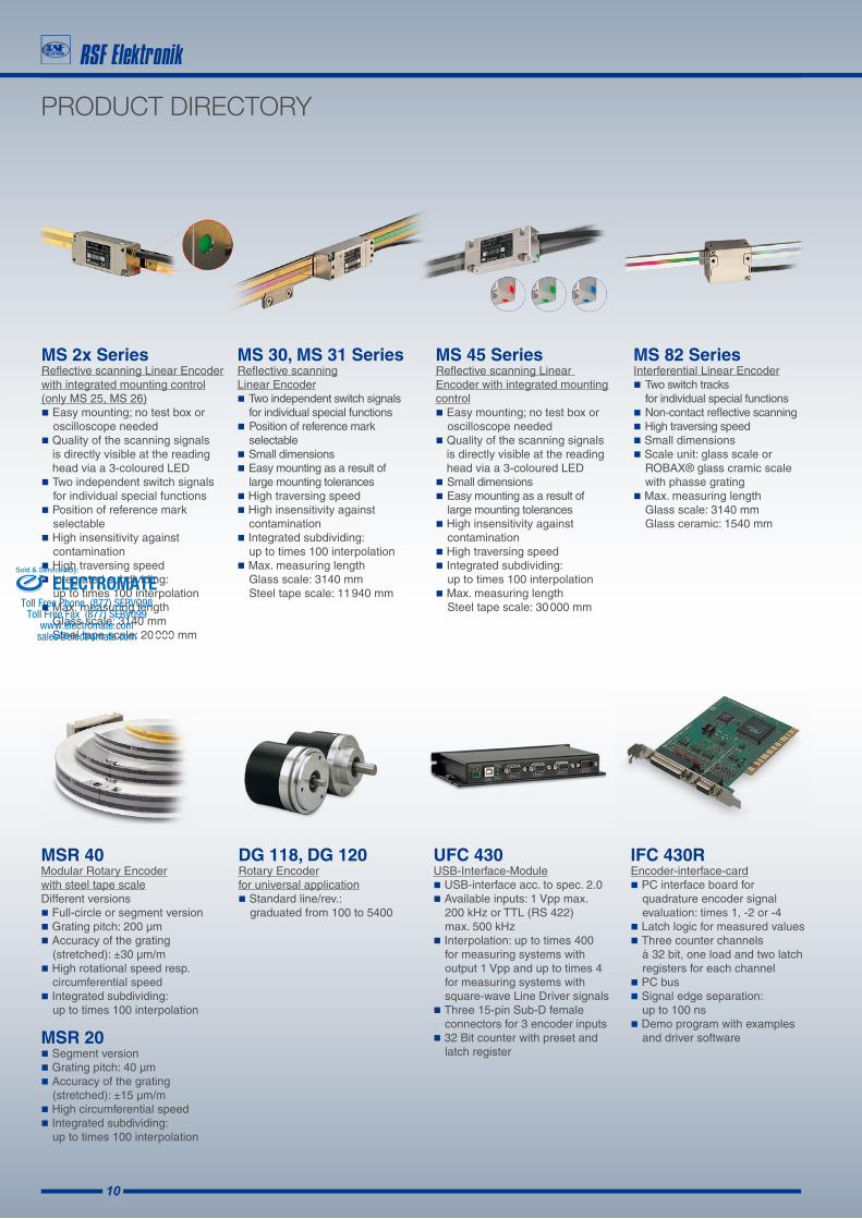
PRODUCT DIRECTORY
MS 2x SeriesReflective scanning Linear Encoder with integrated mounting control (only MS 25, MS 26)Easy mounting; no test box or oscilloscope needed Quality of the scanning signals is directly visible at the reading head via a 3-coloured LED Two independent switch signals for individual special functions Position of reference mark selectable High insensitivity against contaminationHigh traversing speedIntegrated subdividing: up to times 100 interpolationMax. measuring length
Glass scale: 3140 mmSteel tape scale: 20 000 mm
MS 30, MS 31 SeriesReflective scanning Linear EncoderTwo independent switch signals for individual special functions Position of reference mark selectableSmall dimensionsEasy mounting as a result of large mounting tolerancesHigh traversing speedHigh insensitivity against contaminationIntegrated subdividing: up to times 100 interpolationMax. measuring length Glass scale: 3140 mm Steel tape scale: 11 940 mm
MS 82 SeriesInterferential Linear EncoderTwo switch tracks for individual special functionsNon-contact reflective scanningHigh traversing speedSmall dimensionsScale unit: glass scale or ROBAX® glass cramic scale with phasse grating Max. measuring length Glass scale: 3140 mm Glass ceramic: 1540 mm
MS 45 SeriesReflective scanning Linear Encoder with integrated mounting control Easy mounting; no test box or oscilloscope needed Quality of the scanning signals is directly visible at the reading head via a 3-coloured LEDSmall dimensionsEasy mounting as a result of large mounting tolerancesHigh insensitivity against contaminationHigh traversing speedIntegrated subdividing: up to times 100 interpolationMax. measuring length Steel tape scale: 30 000 mm
MSR 40Modular Rotary Encoder with steel tape scale Different versionsFull-circle or segment version Grating pitch: 200 µm Accuracy of the grating (stretched): ±30 µm/m High rotational speed resp. circumferential speed Integrated subdividing: up to times 100 interpolation
MSR 20Segment version Grating pitch: 40 µmAccuracy of the grating (stretched): ±15 µm/mHigh circumferential speedIntegrated subdividing: up to times 100 interpolation
UFC 430 USB-Interface-Module USB-interface acc. to spec. 2.0 Available inputs: 1 Vpp max. 200 kHz or TTL (RS 422) max. 500 kHzInterpolation: up to times 400 for measuring systems with output 1 Vpp and up to times 4 for measuring systems with square-wave Line Driver signalsThree 15-pin Sub-D female connectors for 3 encoder inputs 32 Bit counter with preset and latch register
IFC 430R Encoder-interface-card PC interface board for quadrature encoder signal evaluation: times 1, -2 or -4Latch logic for measured values Three counter channels à 32 bit, one load and two latch registers for each channelPC busSignal edge separation: up to 100 ns Demo program with examples and driver software
DG 118, DG 120Rotary Encoder for universal applicationStandard line/rev.: graduated from 100 to 5400
ELECTROMATEToll Free Phone (877) SERVO98
Toll Free Fax (877) SERV099www.electromate.com
Sold & Serviced By:
11
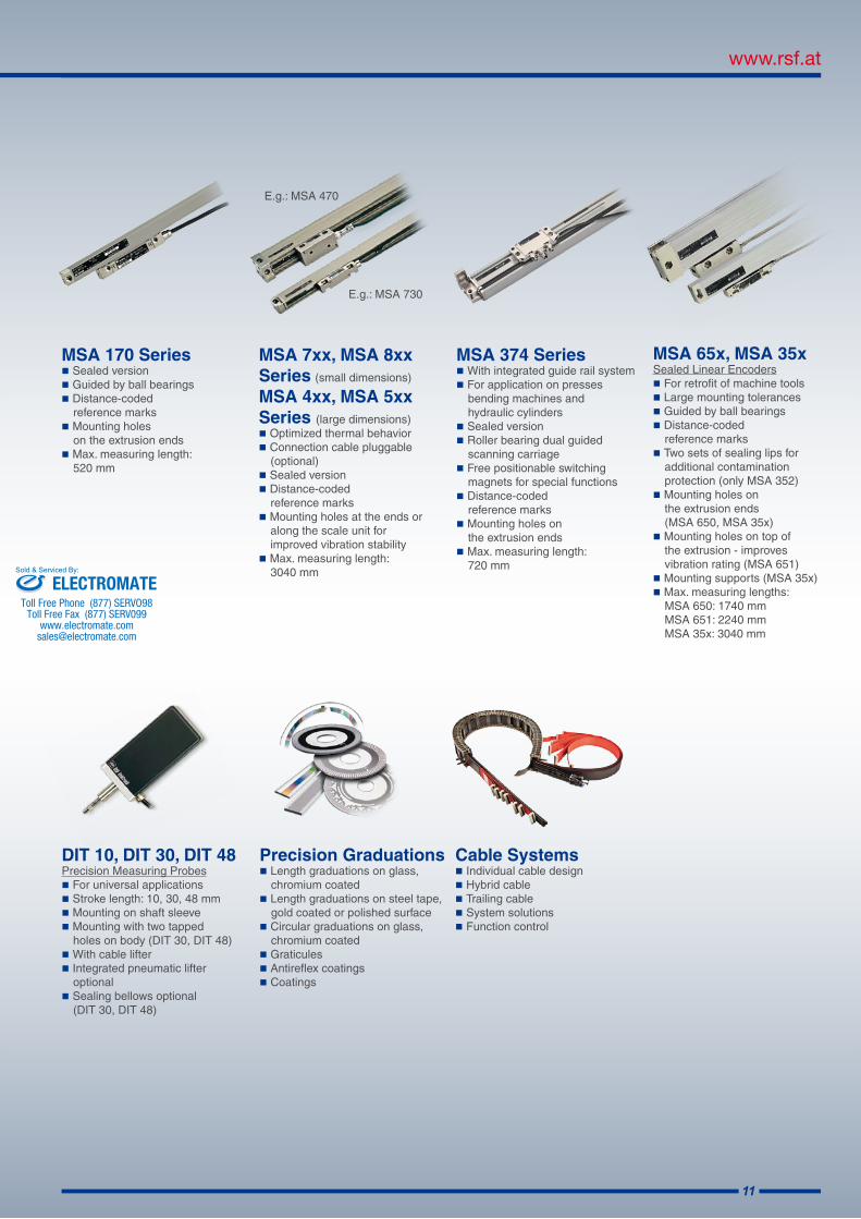
E.g.: MSA 730
E.g.: MSA 470
MSA 65x, MSA 35xSealed Linear EncodersFor retrofit of machine toolsLarge mounting tolerances Guided by ball bearingsDistance-coded reference marks Two sets of sealing lips for additional contamination protection (only MSA 352)Mounting holes on the extrusion ends (MSA 650, MSA 35x)Mounting holes on top of the extrusion - improves vibration rating (MSA 651) Mounting supports (MSA 35x)Max. measuring lengths: MSA 650: 1740 mm MSA 651: 2240 mm MSA 35x: 3040 mm
MSA 170 SeriesSealed versionGuided by ball bearingsDistance-coded reference marks Mounting holes on the extrusion endsMax. measuring length: 520 mm
MSA 7xx, MSA 8xx Series (small dimensions) MSA 4xx, MSA 5xx Series (large dimensions)Optimized thermal behavior Connection cable pluggable (optional) Sealed versionDistance-coded reference marksMounting holes at the ends or along the scale unit for improved vibration stabilityMax. measuring length: 3040 mm
MSA 374 SeriesWith integrated guide rail systemFor application on presses bending machines and hydraulic cylindersSealed versionRoller bearing dual guided scanning carriageFree positionable switching magnets for special functionsDistance-coded reference marks Mounting holes on the extrusion endsMax. measuring length: 720 mm
Cable SystemsIndividual cable designHybrid cableTrailing cableSystem solutionsFunction control
DIT 10, DIT 30, DIT 48Precision Measuring ProbesFor universal applicationsStroke length: 10, 30, 48 mmMounting on shaft sleeveMounting with two tapped holes on body (DIT 30, DIT 48)With cable lifterIntegrated pneumatic lifter optionalSealing bellows optional (DIT 30, DIT 48)
Precision GraduationsLength graduations on glass, chromium coatedLength graduations on steel tape, gold coated or polished surfaceCircular graduations on glass, chromium coatedGraticules Antireflex coatings Coatings
ELECTROMATEToll Free Phone (877) SERVO98
Toll Free Fax (877) SERV099www.electromate.com
Sold & Serviced By:

A-5121 Tarsdorf +43 (0)6278 / 8192-0 FAX +43 (0)6278 / 8192-79 e-mail: [email protected] internet: www.rsf.at
Ges.m.b.H.
Date 12/2012 Art.Nr. 827373-01 Doc.Nr. D827373-01-A-01 Technical adjustments in reserve!
Certified acc. toDIN EN ISO 9001
DIN EN ISO 14001
Linear EncodersDigital ReadoutsPrecision Graduations Cable Systems
DISTRIBUTION CONTACTS
AustriaCorporate
Head Quarters
RSF Elektronik Ges.m.b.H.A-5121 Tarsdorf
+43 (0) 62 78 81 92-0 +43 (0) 62 78 81 92-79
e-mail: [email protected]: www.rsf.at
China RSF Elektronik GmbH Tian Wei San Jie,Area A, Beijing Tianzhu Airport Industrial ZoneShunyi District101312 BeijingP.R. China
+86 (0) 10 80 42 02 88 +86 (0) 10 80 42 02 90
e-mail: [email protected]: www.rsf.cn
Korea HEIDENHAIN LTD. 202 Namsung Plaza, 9th Ace Techno Tower, 130, Digital-Ro, Geumcheon-Gu, Seoul, Korea 153-782
+82 (0) 2 20 28 74 30e-mail: [email protected]: www.rsf.co.kr
USA HEIDENHAIN CORPORATION333 East State ParkwaySchaumburg, IL 60173-5337
+1 847 490 11 91e-mail: [email protected]: www.rsf.net
HEIDENHAIN (GB) Ltd.200 London RoadBurgess HillWest Sussex RH15 9RD
+44 (0)1444 238550 +44 (0)1444 870024
e-mail: [email protected]
HEIDENHAIN FRANCE sarl2 Avenue de la Christallerie92310 Sèvres
+33 1 41 14 30 00 +33 1 41 14 30 30
e-mail: [email protected]
United Kingdom
France
Switzerland RSF Elektronik (Schweiz) AGVieristrasse 14CH-8603 Schwerzenbach
+41 44 955 10 50 +41 44 955 10 51
e-mail: [email protected]: www.rsf.ch
HEIDENHAIN ITALIANA S.r.l.Via Asiago, 1420128 Milano (MI)
+39 02 27075-1 +39 02 27075-210
e-mail: [email protected]
Italy
Slovenia RSF Elektronik prodaja, d.o.o.Jozeta Jame 14SI-1210 Ljubljana
+386 (0) 1 519 88 80 +386 (0) 1 519 88 80
e-mail: [email protected]
ELECTROMATEToll Free Phone (877) SERVO98
Toll Free Fax (877) SERV099www.electromate.com
Sold & Serviced By:
Related Documents