Product Data Sheet 00813-0100-2654, Rev GB April 2010 Sensors and Accessories (English) www.rosemount.com • Standard Immersion Sensors • Available with Many Standard Process Connections • Calibration Capabilities Content Introduction . . . . . . . . . . . . . . . . . . . . . . . . . . . . . . . . . . . . . . . . . . . . . . . . . . . . . . . . . . . . . . page 2 Threaded Mount Sensors and Assemblies . . . . . . . . . . . . . . . . . . . . . . . . . . . . . . . . . . . . . page 10 Ordering Tables Series 68 RTD Sensor Assemblies WITHOUT Thermowell. . . . . . . . . . . . . . . . . . . . . . page 13 Series 68 RTD Sensor Assemblies WITH Thermowell. . . . . . . . . . . . . . . . . . . . . . . . . page 17 Series 78 RTD Sensor Assemblies WITHOUT Thermowell. . . . . . . . . . . . . . . . . . . . . . page 25 Series 78 RTD Sensor Assemblies WITH Thermowell. . . . . . . . . . . . . . . . . . . . . . . . . . page 29 Series 68Q Sanitary Platinum RTD Sensor Assemblies . . . . . . . . . . . . . . . . . . . . . . . . page 37 Series 58C Cut-to-Fit RTD Sensors . . . . . . . . . . . . . . . . . . . . . . . . . . . . . . . . . . . . . . . . page 40 Series 183 Thermocouple Sensor Assemblies WITHOUT Thermowell . . . . . . . . . . . . . page 42 Series 183 Thermocouple Sensor Assemblies WITH Thermowell . . . . . . . . . . . . . . . . page 45 Calibration . . . . . . . . . . . . . . . . . . . . . . . . . . . . . . . . . . . . . . . . . . . . . . . . . . . . . . . . . . . . . . page 51 Mounting Accessories . . . . . . . . . . . . . . . . . . . . . . . . . . . . . . . . . . . . . . . . . . . . . . . . . . . . . page 63 Ordering Tables Connection Head Model Numbers . . . . . . . . . . . . . . . . . . . . . . . . . . . . . . . . . . . . . . . . . page 64 Extension . . . . . . . . . . . . . . . . . . . . . . . . . . . . . . . . . . . . . . . . . . . . . . . . . . . . . . . . . . . . page 65 Compression Fittings, 316 SST . . . . . . . . . . . . . . . . . . . . . . . . . . . . . . . . . . . . . . . . . . . page 66 Series 91 Thermowell . . . . . . . . . . . . . . . . . . . . . . . . . . . . . . . . . . . . . . . . . . . . . . . . . . page 71 Hazardous Area Approvals . . . . . . . . . . . . . . . . . . . . . . . . . . . . . . . . . . . . . . . . . . . . . . . . . page 82 Temperature Sensors and Accessories (English)

Welcome message from author
This document is posted to help you gain knowledge. Please leave a comment to let me know what you think about it! Share it to your friends and learn new things together.
Transcript

Product Data Sheet00813-0100-2654, Rev GBApril 2010 Sensors and Accessories (English)
Temperature Sensors and Accessories
• Standard Immersion Sensors
• Available with Many Standard Process Connections
• Calibration Capabilities
(English)
www.ro
Content
Introduction . . . . . . . . . . . . . . . . . . . . . . . . . . . . . . . . . . . . . . . . . . . . . . . . . . . . . . . . . . . . . . page 2
Threaded Mount Sensors and Assemblies . . . . . . . . . . . . . . . . . . . . . . . . . . . . . . . . . . . . . page 10
Ordering Tables
Series 68 RTD Sensor Assemblies WITHOUT Thermowell. . . . . . . . . . . . . . . . . . . . . . page 13
Series 68 RTD Sensor Assemblies WITH Thermowell. . . . . . . . . . . . . . . . . . . . . . . . . page 17
Series 78 RTD Sensor Assemblies WITHOUT Thermowell. . . . . . . . . . . . . . . . . . . . . . page 25
Series 78 RTD Sensor Assemblies WITH Thermowell. . . . . . . . . . . . . . . . . . . . . . . . . . page 29
Series 68Q Sanitary Platinum RTD Sensor Assemblies . . . . . . . . . . . . . . . . . . . . . . . . page 37
Series 58C Cut-to-Fit RTD Sensors . . . . . . . . . . . . . . . . . . . . . . . . . . . . . . . . . . . . . . . . page 40
Series 183 Thermocouple Sensor Assemblies WITHOUT Thermowell . . . . . . . . . . . . . page 42
Series 183 Thermocouple Sensor Assemblies WITH Thermowell . . . . . . . . . . . . . . . . page 45
Calibration . . . . . . . . . . . . . . . . . . . . . . . . . . . . . . . . . . . . . . . . . . . . . . . . . . . . . . . . . . . . . . page 51
Mounting Accessories . . . . . . . . . . . . . . . . . . . . . . . . . . . . . . . . . . . . . . . . . . . . . . . . . . . . . page 63
Ordering Tables
Connection Head Model Numbers . . . . . . . . . . . . . . . . . . . . . . . . . . . . . . . . . . . . . . . . . page 64
Extension . . . . . . . . . . . . . . . . . . . . . . . . . . . . . . . . . . . . . . . . . . . . . . . . . . . . . . . . . . . . page 65
Compression Fittings, 316 SST . . . . . . . . . . . . . . . . . . . . . . . . . . . . . . . . . . . . . . . . . . . page 66
Series 91 Thermowell . . . . . . . . . . . . . . . . . . . . . . . . . . . . . . . . . . . . . . . . . . . . . . . . . . page 71
Hazardous Area Approvals . . . . . . . . . . . . . . . . . . . . . . . . . . . . . . . . . . . . . . . . . . . . . . . . . page 82
semount.com
Administrator
Rectangle
Product Data Sheet00813-0100-2654, Rev GB
April 2010Sensors and Accessories (English)
Introduction
OVERVIEWEmerson Process Management offers a wide variety of RTD and thermocouple sensors that are available alone or as complete assemblies including connection heads, thermowells, and extension fittings. In addition to complete assemblies, Emerson Process Management offers heads, coupling/nipple and union/nipple extensions, compression fittings, and thermowells.
Using this Product Data Sheet (PDS)Use this PDS to order complete temperature sensor assemblies, which include sensors, thermowells, extensions, and connection heads. These options can also be ordered separately. For example, you can order a thermowell, extension, or connection head for use with an existing sensor. In each case it is important to know and understand the sections of this PDS when specifying the items.
Threaded Sensors and Assemblies• Includes descriptions, specifications, and ordering information
for Series 58C, 68, 68Q, and 78 RTDs, and the Series 183 thermocouples.
• Includes information for ordering sensors, connection heads, extensions, and thermowells as complete assemblies.
Calibration• Includes characterization schedules and information for
ordering calibrated Series 68, 68Q, and 78 RTD Sensors.
• Includes information regarding the use of Callendar-Van Dusen constants to match specific Series 68, 68Q, and 78 RTDs to Rosemount Smart Temperature Transmitters.
Mounting Accessories• Includes descriptions, specifications, and ordering information
for temperature accessories such as thermowells, extensions, connection heads, mounting adapters, lead wire extensions, connectors, seals, and thermowells.
Hazardous Area Approvals• Includes descriptions of the FM, CSA, SAA, and ATEX
approvals for sensors and connection heads.
Configuration Data Sheet• Provides a form used for thermowell application calculations.
Series 58C, 68, 68Q, and 78 platinum RTD temperature sensors are primarily used when high accuracy, durability, and long-term stability are required. These sensors conform to international standards: IEC-751, EN 60751, and BS EN 60751.(1)
Series 58C platinum RTD temperature sensors:
• Combine an economical thin-film design with a sheath that can be shortened to any length with tubing cutter.
Series 68Q Quick Response Sanitary RTD sensors:
• Conform to 3–A Sanitary Standards and feature product contact surfaces designed for CIP cleaning.
Series 68 platinum RTD temperature sensors:
• Provide high performance in an economical thin-film design.
Series 78 platinum RTDs temperature sensors:
• Use a wire-wound element which allows for a broader measurement range.
ThermocouplesSeries 183 thermocouple temperature sensors conform to ASTM E-230, and are available in types J, K, E, and T.
Series 183 thermocouple temperature sensors are available:
• grounded or ungrounded
• isolated or unisolated
• with immersion lengths from 2 to 48 inches.
(1) 100 ohms at 0 °C, � = 0.00385 ohms/ohm/°C
2

Product Data Sheet00813-0100-2654, Rev GBApril 2010 Sensors and Accessories (English)
The Use of 2-, 3-, and 4- wire RTDsTo help you attain the highest possible temperature measurement accuracy, Rosemount provides 4-wire sensors for all single element RTDs. You can use these RTDs in 2-, 3-, or 4-wire configurations by simply securing the unneeded leads with tape. To properly wire the 4-wire RTD for use in a 2-, 3-, or 4-wire configuration, refer to the following wiring diagrams:
2-wire Configuration2-wire RTDs provide one connection to each end of the sensor. In a 2-wire configuration, lead wires add resistance to the circuit which cannot be compensated. The 2-wire configuration is rarely used because the added lead wire resistance can cause substantial errors in the temperature reading.
3-wire Configuration3-wire RTDs provide one connection to one end of the sensor, and two connections to the other end. The 3-wire approach does not eliminate all lead wire effects. However, for sensors with lead wires of the same length, lead wire effects are slight, and the approach provides reasonable accuracy.
4-wire ConfigurationThe most effective way to eliminate lead wire effects is with two connections at each end of the sensor. 4-wire RTDs fully compensate for lead wire effects.
Benefits and Limitations of RTDs when compared to Thermocouples
Benefits:• Higher accuracy
• Better linearity and long-term stability
• Cold junction compensation not required
• Special extension lead wire not required
• Less susceptible to noise
• Can be “matched” to a Rosemount transmitter with transmitter sensor matching
Limitations• Lower maximum temperature limit
• Slower response time in applications without a thermowell
3

Product Data Sheet00813-0100-2654, Rev GB
April 2010Sensors and Accessories (English)
HOW TO DECIDE WHAT TO ORDER
If Rosemount sensor and model code is visible on the Sensor:
1. If the thermowell is ordered separately (0078P23C30N060) 11th digit = ‘N’
a. Start with immersion length - digits 12-14; 060 = 6.0 in.
b. Add extension length - digits 9 & 10; 30 = 3.0 in. (3 + 6 = 9)
Order the replacement sensor for the total length without connection heads (5th digit N) and extension (8th digit N) 0078N23N00N090
2. If the thermowell is ordered integral to sensor (0078P23C30A060W40) 11th digit = not ‘N’
a. Immersion length ‘U’ is defined by the 12-14th digits; 060 = 6.0 in.
b. Look up ‘L’ length from the correct order chart for given ‘U’ length. This will be 4 inches for short sensors, or a whole number divisible by 3 for sensors longer than 4 inches (4, 6, 9, 12, 15, 18... inches);‘U’ 060 = 9 inches ‘L’
c. Add extension length as defined by 9th and 10th digits; 30 = 3.0 in. to the ‘L’ length found in table. (9” + 3” = 12”, Length code 120)
d. This will be the replacement sensor length ‘X’.
Order sensor without connection head (5th digit N) or extension (8th digit N) 0078N23N00N120
Start (Select One)
Is a sensor and a thermowell needed?
Is a sensor for an existing thermowell
needed?
Is a thermowell for an existing sensor
needed?
YesYesYes
Refer to Table 1. Do any standard lagging length/immersion length combinations meet the requirements?
Yes No
Select a sensor with a thermowell combination
1. Select a sensor without a thermowell combination
2. Select a thermowell
Select a sensor without a thermowell
Select a thermowell
Finish
4

Product Data Sheet00813-0100-2654, Rev GBApril 2010 Sensors and Accessories (English)
If model code is NOT visible on the sensor, follow one of the three instructions below:
1. Measure the inside depth of the thermowell *preferred*
a. Measure down the inside of the thermowell hole to the top-most face of the extension used, or the thermowell if no extension
b. This will be the replacement sensor length if depth = 12.0 in., sensor length will be 12 in.
Order sensor without connection heads (5th digit N) or extension (8th digit N) 0078N23N00N120
2. Measure the overall outside length of the thermowell from end to end.
a. Measure down the outside of the thermowell from the tip to the end face of the extension if used, or the thermowell if no extension.
b. Subtract 1/4 in. to account for thickness of the thermowell at the tip.
c. This will be the replacement sensor length. Overall length = 12.25 in., the replacement will be 12 in.
Order sensor without connection heads (5th digit N) or extension (8th digit N) 0078N23N00N120
3. Measure the old sensor length from tip to the flat face of the threaded process connection.
a. Determine if the sensor is spring loaded or general purpose (welded) where the sensor sheath meets the threaded adaptor.
b. For spring loaded sensors, the measurement of the exposed sheath from tip of the start of the threaded portion will be the same as the replacement sensor length.
• Normal spring compression for a Rosemount sensor is assumed to be 1/2 in. and the normal thread engagement is also assumed to be 1/2 in.
• Round to the nearest whole 1/4 in. increment as the spring will make up any small differences
• Replacement sensor for a spring loaded sensor measuring 6.5 inches will be 6.5 in. lengthOrder sensor without connection heads (5th digit N) or extension (8th digit N) 0078N15N00N065
c. For general purpose sensors with the distance from tip to threaded adapter:
• Add 1/4 in. to allow clearance, preventing bottoming sensor during installation.
• Add 1/2 in. for the thread engagement of the sensor in the thermowell.
• The replacement sensor for a general purpose sensor measuring 5.75 in. from the tip to the threaded adaptor is 6.5 in. (53/4 + 1/4 + 1/2 = 61/2 in).
Order sensor without connection heads (5th digit N) or extension (8th digit N) 0078N15N00N065
If model code is visible on the thermowell (0091A060W40T015P) follow the instructions below to determine sensor model number:
a. Start with immersion length digits 6-8, 060 = 6.0 in.
b. Add additional lagging length digits 13-15, 015 = 1.5 in.
c. To those lengths add 1.5 in. (this is the additional standard lagging length on all Rosemount thermowells) 1.75 in. minus (0.25 in. thermowell tip thickness) = 1.50 in.
d. 6.0 +1.5 +1.5 = 9 in.
Order replacement sensor 0078N23N00N090
5

Product Data Sheet00813-0100-2654, Rev GB
April 2010Sensors and Accessories (English)
SPRING-LOADED SENSOR DIMENSIONSWhen a spring-loaded sensor is used properly, the spring should be compressed approximately 1/2-inch. Therefore, all measurements of spring-loaded sensors are made with the spring compressed. If you measure an existing spring-loaded sensor while it is in a relaxed state, you must subtract 1/2-inch to arrive at the installed length (X) that must be ordered. See Figure 1.
FIGURE 1. Spring Loaded Sensors Dimensions
Determining the Length (L) of a spring-loaded sensor to be used with an existing non-Rosemount ThermowellSee Figure 1, Figure 3, and Figure 4.
Compressed Spring Loaded Sensor
Spring loaded sensor in a compressed state: The actual sensor length is measured when the spring is compressed approximately 1/2-in. shorter than the relaxed sensor.
Relaxed Spring Loaded Sensor
Spring loaded sensor in a relaxed state: Normally, when a spring loaded sensor is measured, it is in a relaxed state. You must subtract 1/2-in. from your measurement to order a replacement sensor. Rosemount Inc. assumes that the sensor length you specify is that of a compressed sensor.
Installed (X) Length[Spring Compressed
0.5 (13) nominal]
3.45 (88) Max.
0.5
Installed (X) Length + 0.5 in.2.95 (88) Max.
1. Remove the existing generic sensor from the installed thermowell. Length Code Key
2. Measure the sensor length with the spring in the relaxed state (as shown inFigure 1). Measure from the tip of the sensor to the maximum thread engagement point (0.53 in. into the threads).
L Thermowell length minus 0.25 in.U Immersion length into processT Lagging length
3. Subtract 0.5 inches from your measurement. The resulting length is (X). E Extension fitting length4. If the sensor is installed with an extension, measure the extension length (E), as
shown in Figure 4. If the sensor is not installed with an extension, let (E) = 0.X Sensor lengthUse the following equations to determine all lengths
L = U + T + 1.5X = E + LX = E + U + T + 1.5
5. Since (X) = (E) + (L), subtract (E) from (X) to find (L). Use the resulting length (L) in the Section 2 ordering tables to choose the correct length of sensor.
6

Product Data Sheet00813-0100-2654, Rev GBApril 2010 Sensors and Accessories (English)
FIGURE 2. Thermowell Dimensions (use with Table 1)
TABLE 1. Dimensions for thermowells when ordered with sensors (U), (L), and (T). Use with Figure 2.
Ordering a Sensor and a ThermowellSee Figure 2 and Table 1 and Figure 3 and Figure 4. Use the following Procedure to determine if a standard lagging length can be use with the sensor and thermowell.
Sensor with Thermowell (no extensions)
0.25-in.
T1.75-in.
U
L
Dimensions (in.)(1)
Code (U) (L) (T) Code (U) (L) (T) Code (U) (L) (T)
020 2.0 4.0 0.5 090 9.0 12.0 1.5 160 16.0 18.0 0.5025 2.5 4.0 0.0 095 9.5 12.0 1.0 165 16.5 18.0 0.0030 3.0 6.0 1.5 100 10.0 12.0 0.5 170 17.0 21.0 2.5035 3.5 6.0 1.0 105 10.5 12.0 0.0 175 17.5 21.0 2.0040 4.0 6.0 0.5 110 11.0 15.0 2.5 180 18.0 21.0 1.5045 4.5 6.0 0.0 115 11.5 15.0 2.0 185 18.5 21.0 1.0050 5.0 9.0 2.5 120 12.0 15.0 1.5 190 19.0 21.0 0.5055 5.5 9.0 2.0 125 12.5 15.0 1.0 195 19.5 21.0 0.0060 6.0 9.0 1.5 130 13.0 15 0.5 200 20.0 24.0 2.5065 6.5 9.0 1.0 135 13.5 15.0 0.0 205 20.5 24.0 2.0070 7.0 9.0 0.5 140 14.0 18.0 2.5 210 21.0 24.0 1.5075 7.5 9.0 0.0 145 14.5 18.0 2.0 215 21.5 24.0 1.0080 8.0 12.0 2.5 150 15.0 18.0 1.5 220 22.0 24.0 0.5085 8.5 12.0 2.0 155 15.5 18.0 1.0 225 22.5 24.0 0.0
(1) L = U + T + 1.5
1. Determine the (U), (T), and (E) lengths necessary for your installation. If you do not need an extension, (E) = 0 (zero).Note: If your existing sensor/thermowell combination is different than Figure 3, refer to the drawings on the following pages.
Length Code Key
L Thermowell length minus 0.25 in.U Immersion length into processT Lagging length
2. Find your immersion length (U) on Table 1 above and compare the corresponding lagging length (T) to the lagging length that you previously determined.
E Extension fitting lengthX Sensor length
3. If your lengths match the values on the line that corresponds to your required immersion length, order your sensor and thermowell together.
If your lengths do not match the values on the line that corresponds to your measured immersion length, order your sensor and thermowell separately. Solve for (L) using the equation (L) = (U) + (T) + 1.5 (since (L) is required when ordering the sensor separately from the thermowell).
Use the following equations to determine all lengths
L = U + T + 1.5X = E + LX = E + U + T + 1.5
7
Product Data Sheet00813-0100-2654, Rev GB
April 2010Sensors and Accessories (English)
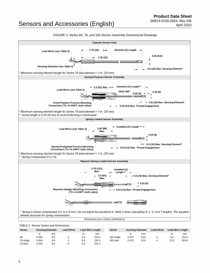
FIGURE 3. Series 68, 78, and 183 Sensor Assembly Dimensional Drawings
TABLE 2. Sensor Series and Dimensions
Capsule Sensor Only
* Maximum sensing element length for Series 78 dual-element = 1-in. (25 mm)General Purpose Sensor Assembly
* Maximum sensing element length for Series 78 dual-element = 1-in. (25 mm)** Actual length is 0.25 (6) less to avoid bottoming in thermowell
Spring Loaded Sensor Assembly
* Maximum sensing element length for Series 78 dual-element = 1-in. (25 mm)** Spring Compressed 0.5 (13)
Bayonet Spring Loaded Sensor Assembly
* Spring is shown compressed 0.5 -in.(13 mm.) Do not adjust the equations in Table 2 when calculating X, L, U, and T lengths. The equation already accounts for spring compression.
Dimensions are in inches (millimeters)
Housing Diameter (see Table 2)
Lead Wires (see Table 2) 1.75 (44) Nominal (X) Length
1.25 (32)0.35 (8.9)
0.6 (15) Max. Sensing Element*
3.2 (81) Max.Lead Wires (see Table 2)
Fixed-Position Process MountingConnection (1/2–14 ANPT, both sides)
Weld 360°0.25 (6)
0.25 (6)
0.6 (15) Max. Sensing Element*
0.53 (13) Max. Thread Engagement
Nominal (X) Length**
0.53 (13) Max. Thread Engagement
0.6 (15) Max. Sensing Element*
0.25 (6)
Installed (X) Length **
Spring-Positioned Process MountingConnection (1/2–14 ANPT, both sides)
3.45 (88) Max.
Lead Wires (see Table 2)
Bayonet Adapter Mounting Connection(1/2–14 ANPT, both sides)
0.53 (13) Max. Thread Engagement
0.25 (6)
Installed (X) Length **
4.75 (121) Max.
2.5 (64) Max.
0.6 (15) Max. Sensing Element*
Series Housing Diameter Lead Wires Lead Wire Length Series Housing Diameter Lead Wires Lead Wire Length
in mm in mm in mm in mm68 0.350 8.0 4 6.0 152.4 183 single 0.375 9.53 2 6.0 152.478 single 0.350 8.0 4 6.0 152.4 183 dual 0.375 9.53 4 12.0 304.878 dual 0.350 8.0 6 6.0 152.4
8

Product Data Sheet00813-0100-2654, Rev GBApril 2010 Sensors and Accessories (English)
FIGURE 4. Series 68, 78, and 183 Sensor Assembly Length Code Drawings
Sensor with Thermowell (No Extension)
Sensor with Extension (No Thermowell)
Sensor Installed in Connection Head (Flat Cover) with Union and Nipple Extensions and Thermowell
Dimensions are in inches (millimeters)
Sensor Mounting Connection0.25 (6)
T + 1.75 (44)
X
L
U
Sensor Mounting Connection
Coupling
Nipple
1/2–14 ANPT Thread
E
X
L
5.5 (140)Extended Cover
Sensor Mounting Connection
3/4–14 ANPT
Chain
0.25 (6)
Thermowell
3.5 (89)Flat
Cover
Nipple
Union
T + 1.75 (44)
E L
X
U
9

Product Data Sheet00813-0100-2654, Rev GB
April 2010Sensors and Accessories (English)
Threaded Sensors and Assemblies
Series 68, 68Q, and 78 RTD and Series 183 Thermocouple Sensors may be ordered as complete assemblies. These assemblies provide a complete, yet simple means of specifying the proper industrial hardware for most temperature measurements.
One assembly model number, derived from one ordering table, completely defines the type of sensing element, as well as the material, length, and style of both the extension fittings and thermowells. All sensor assemblies are sized and inspected by Rosemount Inc. to ensure complete component compatibility and performance.
FIGURE 5. Individual Components of a Complete Temperature Assembly
Dimensions are in inches (millimeters)
0.5 (13) Nominal Engagement
Standard Adapter Sensor Assembly
Threaded
Welded
Flanged
Union-Nipple
Coupling-Nipple
Th
ermo
wells
Lead Wire Extensions and Seals
Flat or Extended Cover Aluminum Connection Heads
Polypropylene Connection Head
Optional Identification TagX
0.5 (13) Nominal Engagement
E
Exte
nsio
ns
L
Rosemount Aluminum Connection Head
T+1.75
U
10
Product Data Sheet00813-0100-2654, Rev GBApril 2010 Sensors and Accessories (English)
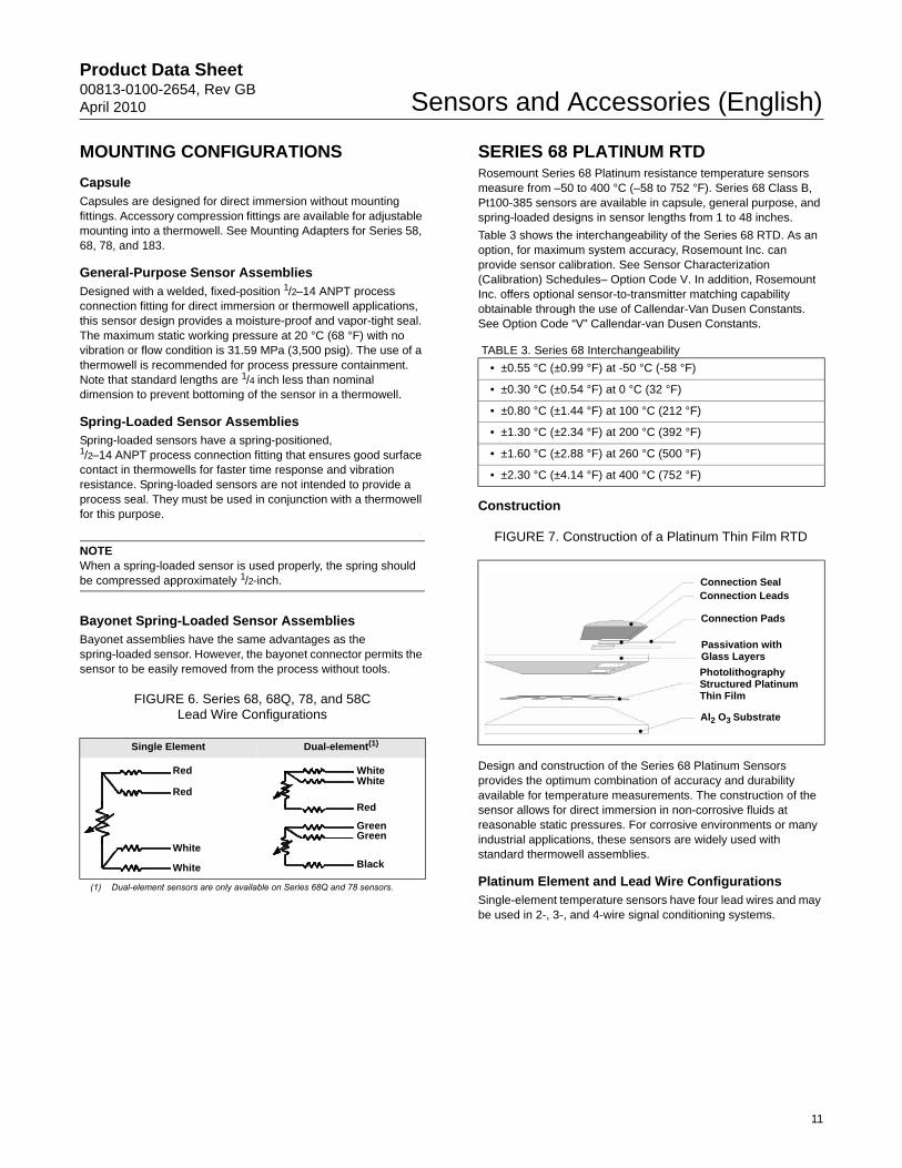
MOUNTING CONFIGURATIONS
CapsuleCapsules are designed for direct immersion without mounting fittings. Accessory compression fittings are available for adjustable mounting into a thermowell. See Mounting Adapters for Series 58, 68, 78, and 183.
General-Purpose Sensor AssembliesDesigned with a welded, fixed-position 1/2–14 ANPT process connection fitting for direct immersion or thermowell applications, this sensor design provides a moisture-proof and vapor-tight seal. The maximum static working pressure at 20 °C (68 °F) with no vibration or flow condition is 31.59 MPa (3,500 psig). The use of a thermowell is recommended for process pressure containment. Note that standard lengths are 1/4 inch less than nominal dimension to prevent bottoming of the sensor in a thermowell.
Spring-Loaded Sensor AssembliesSpring-loaded sensors have a spring-positioned,1/2–14 ANPT process connection fitting that ensures good surface contact in thermowells for faster time response and vibration resistance. Spring-loaded sensors are not intended to provide a process seal. They must be used in conjunction with a thermowell for this purpose.
NOTEWhen a spring-loaded sensor is used properly, the spring should be compressed approximately 1/2-inch.
Bayonet Spring-Loaded Sensor AssembliesBayonet assemblies have the same advantages as the spring-loaded sensor. However, the bayonet connector permits the sensor to be easily removed from the process without tools.
FIGURE 6. Series 68, 68Q, 78, and 58C Lead Wire Configurations
SERIES 68 PLATINUM RTDRosemount Series 68 Platinum resistance temperature sensors measure from –50 to 400 °C (–58 to 752 °F). Series 68 Class B, Pt100-385 sensors are available in capsule, general purpose, and spring-loaded designs in sensor lengths from 1 to 48 inches.
Table 3 shows the interchangeability of the Series 68 RTD. As an option, for maximum system accuracy, Rosemount Inc. can provide sensor calibration. See Sensor Characterization (Calibration) Schedules– Option Code V. In addition, Rosemount Inc. offers optional sensor-to-transmitter matching capability obtainable through the use of Callendar-Van Dusen Constants. See Option Code “V” Callendar-van Dusen Constants.
TABLE 3. Series 68 Interchangeability
Construction
FIGURE 7. Construction of a Platinum Thin Film RTD
Design and construction of the Series 68 Platinum Sensors provides the optimum combination of accuracy and durability available for temperature measurements. The construction of the sensor allows for direct immersion in non-corrosive fluids at reasonable static pressures. For corrosive environments or many industrial applications, these sensors are widely used with standard thermowell assemblies.
Platinum Element and Lead Wire ConfigurationsSingle-element temperature sensors have four lead wires and may be used in 2-, 3-, and 4-wire signal conditioning systems.
Single Element Dual-element(1)
(1) Dual-element sensors are only available on Series 68Q and 78 sensors.
Red
Red
White
White
WhiteWhite
GreenGreen
Red
Black
• ±0.55 °C (±0.99 °F) at -50 °C (-58 °F)
• ±0.30 °C (±0.54 °F) at 0 °C (32 °F)
• ±0.80 °C (±1.44 °F) at 100 °C (212 °F)
• ±1.30 °C (±2.34 °F) at 200 °C (392 °F)
• ±1.60 °C (±2.88 °F) at 260 °C (500 °F)
• ±2.30 °C (±4.14 °F) at 400 °C (752 °F)
Connection SealConnection Leads
Connection Pads
Passivation with Glass Layers
Photolithography Structured Platinum Thin Film
Al2 O3 Substrate
11

Product Data Sheet00813-0100-2654, Rev GB
April 2010Sensors and Accessories (English)
Specifications
Performance
Temperature Range–50 to 400 °C (–58 to 752 °F)
Effect of Temperature Cycling±0.05% (0.13 °C or 0.23 °F) maximum ice-point resistance shift following 10 cycles over the specified temperature range.
Stability±0.11% maximum ice-point resistance shift following 1,000 hours at maximum specified temperature (400 °C).
Maximum Hysteresis±0.1% of operating temperature range.
Time Constant12 seconds maximum required to reach 63.2% sensor response in water flowing at 3 ft/s (0.91 m/s).
Nominal R0 100 OhmNominal alpha .00385 C-1
Physical Specifications
Sheath Material316 SST. / 321 SST.
Lead WirePTFE insulated, nickel-coated, 22-gauge stranded copper wire.
Identification DataThe model, serial numbers, and up to six lines of permanent tagging information are etched on each sensor. Stainless steel tags are available upon request.
Weight• Capsule sensors: 5 oz
• General-purpose and spring-loaded sensors: 9 oz
Environmental Humidity Limits
• Lead seal can withstanding 100% relative humidity.
Vibration Limits• ±0.05% maximum ice-point resistance shift due to 30 minutes
of 14 g peak vibration from 5 to 350 Hz at 20 °C (68 °F) for unsupported stem length of less than 6 inches.
Quality Assurance
• Each sensor is subjected to a resistance accuracy test at 0 °C and a insulation resistance test.
Enclosure Ratings• When installed properly, Rosemount Series 68 sensors are
suitable for indoor and outdoor NEMA 4X and CSA Enclosure Type 4X installations. See Hazardous Area Approvals for complete installation information.
Insulation Resistance 1000 � 106 ohms minimum insulation resistance when measured at 500 Vdc at room temperature.
12

Product Data Sheet00813-0100-2654, Rev GBApril 2010 Sensors and Accessories (English)
ORDERING INFORMATIONTABLE 4. Series 68 RTD Sensor Assemblies WITHOUT Thermowell★ The Standard offering represents the most common options. The starred options (★) should be selected for best delivery.__The Expanded offering is subject to additional delivery lead time.
Model Product Description Available Safety Approvals
0068 Platinum Temperature Sensor WITHOUT thermowell
FM
AT
EX
CS
A
SA
A
Sensor Lead Wire Termination
Standard Standard
R Aluminum Connection Head, Six Terminals, Flat Cover, Unpainted Y Y Y N ★
T Aluminum Connection Head, Six Terminals, Extended Cover, Unpainted Y Y Y N ★
P Aluminum Connection Head, Six Terminals, Flat Cover, Painted Y Y Y N ★
L Aluminum Connection Head, Six Terminals, Extended Cover, Painted Y Y Y N ★
N Sensor only with 6-in. Teflon® -insulated, 22-gauge lead wires Y Y Y N ★
D Rosemount Aluminum Connection Head with 1/2-in. Entries Y Y Y Y ★
Expanded
C Polypropylene Connection Head N N N N
G Rosemount SST Connection Head with 1/2-in. Entries Y Y Y Y
Sensor Type (single element -50 to 400 °C (-58 to 752 °F))
Standard Standard
01(1)(2) Capsule Style ★
11(3) General-purpose style ★
21(4) Spring-loaded style ★
Expanded
31(5) Bayonet spring-loaded style (not available in (X) lengths over 21 inches)
Extension Type
Standard Standard
A Nipple Coupling ★
C Nipple Union ★
N None ★
Extension Length (E)
Standard Standard
00 0.0 in. ★
30 3.0 in. ★
60 6.0 in. ★
Thermowell Material
Standard Standard
N No thermowell required ★
Immersion Length (L)
Standard Standard
010(1)(6) 1.0-in. ★
015 1.5-in. ★
020 2.0-in. ★
025 2.5-in. ★
030 3.0-in. ★
035 3.5-in. ★
040 4.0-in. ★
045 4.5-in. ★
050 5.0-in. ★
055 5.5-in. ★
060 6.0-in. ★
065 6.5-in. ★
070 7.0-in. ★
075 7.5-in. ★
080 8.0-in. ★
085 8.5-in. ★
090 9.0-in. ★
13

Product Data Sheet00813-0100-2654, Rev GB
April 2010Sensors and Accessories (English)
Standard Standard
095 9.5-in. ★
100 10.0-in. ★
105 10.5-in. ★
110 11.0-in. ★
115 11.5-in. ★
120 12.0-in. ★
125 12.5-in. ★
130 13.0-in. ★
135 13.5-in. ★
140 14.0-in. ★
145 14.5-in. ★
150 15.0-in. ★
155 15.5-in. ★
160 16.0-in. ★
165 16.5-in. ★
170 17.0-in. ★
175 17.5-in. ★
180 18.0-in. ★
185 18.5-in. ★
190 19.0-in. ★
195 19.5-in. ★
200 20.0-in. ★
205 20.5-in. ★
210 21.0-in. ★
210 21.5-in. ★
220 22.0-in. ★
225 22.5-in. ★
230 23.0-in. ★
235 23.5-in. ★
240 24.0-in. ★
245 15.5-in. ★
250 25.0-in. ★
260 26.0-in. ★
270 27.0-in. ★
280 28.0-in. ★
290 29.0-in. ★
300 30.0-in. ★
310 31.0-in. ★
320 32.0-in. ★
330 33.0-in. ★
340 34.0-in. ★
350 35.0-in. ★
360 36.0-in. ★
370 37.0-in. ★
380 38.0-in. ★
390 39.0-in. ★
400 40.0-in. ★
410 41.0-in. ★
TABLE 4. Series 68 RTD Sensor Assemblies WITHOUT Thermowell★ The Standard offering represents the most common options. The starred options (★) should be selected for best delivery.__The Expanded offering is subject to additional delivery lead time.
14

Product Data Sheet00813-0100-2654, Rev GBApril 2010 Sensors and Accessories (English)
Standard Standard
420 42.0-in. ★
430 43.0-in. ★
440 44.0-in. ★
450 45.0-in. ★
460 46.0-in. ★
470 47.0-in. ★
480 48.0-in. ★
OPTIONS
Approval Options
Standard Standard
E5 FM Explosion-proof approval (See Figure 26) ★
E6 CSA Explosion-proof approval (See Figure 27) ★
E7(7) SAA Flameproof approval (See Figure 30) ★
Callendar-Van Dussen Constants
Standard Standard
V1-V8 V-Callendar-van Dussen Constant (V4 not available with series 68 sensors) ★
Calibration Schedule
Standard Standard
X8 Customer-Specified Temperature Range Calibration ★
X9 Customer-Specified Single Temperature Point Calibration ★
Calibration Certification
Standard Standard
Q4 Calibration Certification, Customer-Specified Temperature ★
Mounting Adapters
Standard Standard
M5-M7 Mounting adapter: Sensor Compression Fitting: M5= 1/8 - 27 NPT, M6 = 1/4 - 18 NPT, M7 = 1/2 - 14 NPT ★
A Leadkit
Standard Standard
A1-A8 Twisted lead wire extension: A1 = 1.5 ft, A2 = 3.0 ft, A3 = 6.0 ft, A4 = 12 ft, A5 = 24 ft, A6 = 50 ft, A7 = 75 ft, A8 = 100 ft ★
B Leadkit
Standard Standard
B1-B8(8) Shielded cable lead wire extension: B1 = 1.5 ft, B2 = 3.0 ft, B3 = 6.0 ft, B4 = 12 ft, B5 = 24 ft, B6 = 50 ft, B7 = 75 ft, B8 = 100 ft ★
C Leadkit
Standard Standard
C1-C8(8) Armored cable lead wire extension: C1 = 1.5 ft, C2 = 3.0 ft, C3 = 6.0 ft, C4 = 12 ft, C5 = 24 ft, C6 = 50 ft, C7 = 75 ft, C8 = 100 ft ★
D Leadkit
Standard Standard
D1-D8(8) Armored cable lead wire extensions with electrical plug: D1 = 1.5 ft, D2 = 3.0 ft, D3 = 6.0 ft, D4 = 12 ft, D5 = 24 ft, D6 = 50 ft, D7 = 75 ft, D8 = 100 ft
★
L Leadkit
Standard Standard
L1-L8 Armored cable mating plugs with lead wire extension: L1 = 1.5 ft, L2 = 3.0 ft, L3 = 6.0 ft, L4 = 12 ft, L5 = 24 ft, L6 = 50 ft, L7 = 75 ft, L8 = 100 ft
★
F Leadkit
Standard Standard
F1 4-pin bayonet connector ★
H Leadkit
Standard Standard
H1-H8 4-pin connector mating plugs with lead wire extension: H1 = 1.5 ft, H2 = 3.0 ft, H3 = 6.0 ft, H4 = 12 ft, H5 = 24 ft, H6 = 50 ft, H7 = 75 ft, H8 = 100 ft
★
J Leadkit
Standard Standard
J1 Moisture-proof seal assembly for armored cables ★
TABLE 4. Series 68 RTD Sensor Assemblies WITHOUT Thermowell★ The Standard offering represents the most common options. The starred options (★) should be selected for best delivery.__The Expanded offering is subject to additional delivery lead time.
15
Product Data Sheet00813-0100-2654, Rev GB
April 2010Sensors and Accessories (English)
Ordering Example
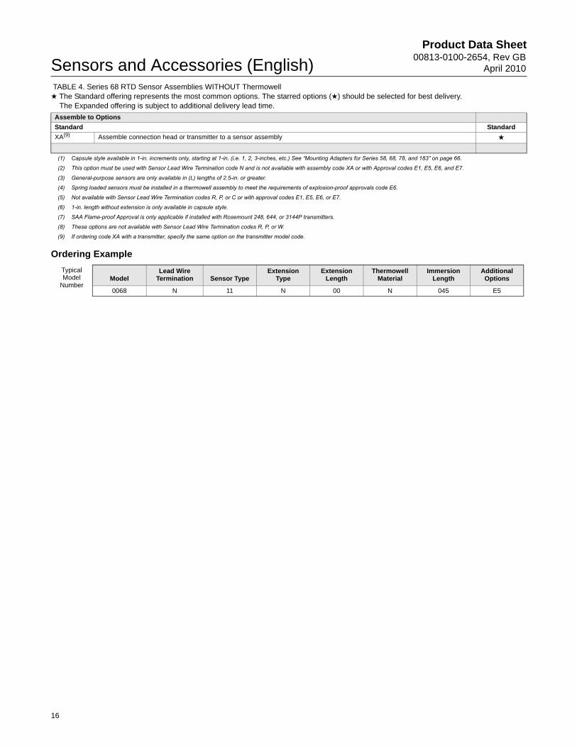
Assemble to Options
Standard Standard
XA(9) Assemble connection head or transmitter to a sensor assembly ★
(1) Capsule style available in 1-in. increments only, starting at 1-in. (i.e. 1, 2, 3-inches, etc.) See “Mounting Adapters for Series 58, 68, 78, and 183” on page 66.
(2) This option must be used with Sensor Lead Wire Termination code N and is not available with assembly code XA or with Approval codes E1, E5, E6, and E7.
(3) General-purpose sensors are only available in (L) lengths of 2.5-in. or greater.
(4) Spring loaded sensors must be installed in a thermowell assembly to meet the requirements of explosion-proof approvals code E6.
(5) Not available with Sensor Lead Wire Termination codes R, P, or C or with approval codes E1, E5, E6, or E7.
(6) 1-in. length without extension is only available in capsule style.
(7) SAA Flame-proof Approval is only applicable if installed with Rosemount 248, 644, or 3144P transmitters.
(8) These options are not available with Sensor Lead Wire Termination codes R, P, or W.
(9) If ordering code XA with a transmitter, specify the same option on the transmitter model code.
TABLE 4. Series 68 RTD Sensor Assemblies WITHOUT Thermowell★ The Standard offering represents the most common options. The starred options (★) should be selected for best delivery.__The Expanded offering is subject to additional delivery lead time.
Typical Model
NumberModel
Lead Wire Termination Sensor Type
Extension Type
Extension Length
Thermowell Material
Immersion Length
Additional Options
0068 N 11 N 00 N 045 E5
16
Product Data Sheet00813-0100-2654, Rev GBApril 2010 Sensors and Accessories (English)
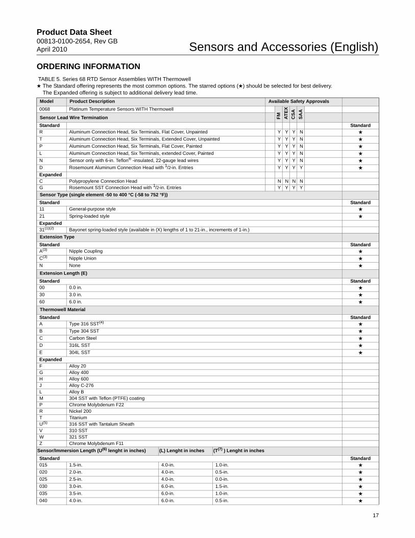
ORDERING INFORMATION
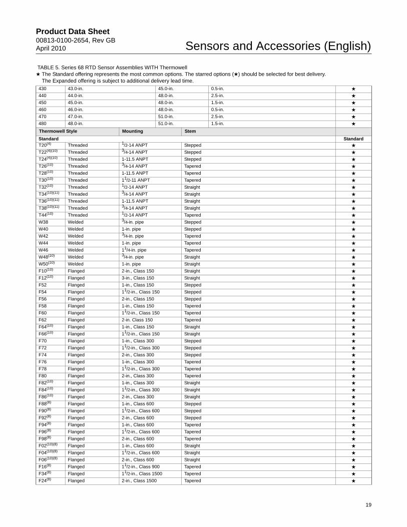
TABLE 5. Series 68 RTD Sensor Assemblies WITH Thermowell ★ The Standard offering represents the most common options. The starred options (★) should be selected for best delivery.__The Expanded offering is subject to additional delivery lead time.
Model Product Description Available Safety Approvals
0068 Platinum Temperature Sensors WITH Thermowell
FM
AT
EX
CS
A
SA
A
Sensor Lead Wire Termination
Standard StandardR Aluminum Connection Head, Six Terminals, Flat Cover, Unpainted Y Y Y N ★
T Aluminum Connection Head, Six Terminals, Extended Cover, Unpainted Y Y Y N ★
P Aluminum Connection Head, Six Terminals, Flat Cover, Painted Y Y Y N ★
L Aluminum Connection Head, Six Terminals, extended Cover, Painted Y Y Y N ★
N Sensor only with 6-in. Teflon® -insulated, 22-gauge lead wires Y Y Y N ★
D Rosemount Aluminum Connection Head with 1/2-in. Entries Y Y Y Y ★
ExpandedC Polypropylene Connection Head N N N NG Rosemount SST Connection Head with 1/2-in. Entries Y Y Y Y
Sensor Type (single element -50 to 400 °C (-58 to 752 °F))
Standard Standard11 General-purpose style ★
21 Spring-loaded style ★
Expanded31(1)(2) Bayonet spring-loaded style (available in (X) lengths of 1 to 21-in., increments of 1-in.)
Extension Type
Standard StandardA(3) Nipple Coupling ★
C(3) Nipple Union ★
N None ★
Extension Length (E)
Standard Standard00 0.0 in. ★
30 3.0 in. ★
60 6.0 in. ★
Thermowell Material
Standard StandardA Type 316 SST(4) ★
B Type 304 SST ★
C Carbon Steel ★
D 316L SST ★
E 304L SST ★
ExpandedF Alloy 20G Alloy 400H Alloy 600J Alloy C-276L Alloy BM 304 SST with Teflon (PTFE) coatingP Chrome Molybdenum F22R Nickel 200T TitaniumU(5) 316 SST with Tantalum SheathV 310 SSTW 321 SSTZ Chrome Molybdenum F11
Sensor/Immersion Length (U(6) lenght in inches) (L) Lenght in inches (T(7) ) Lenght in inches
Standard Standard015 1.5-in. 4.0-in. 1.0-in. ★
020 2.0-in. 4.0-in. 0.5-in. ★
025 2.5-in. 4.0-in. 0.0-in. ★
030 3.0-in. 6.0-in. 1.5-in. ★
035 3.5-in. 6.0-in. 1.0-in. ★
040 4.0-in. 6.0-in. 0.5-in. ★
17

Product Data Sheet00813-0100-2654, Rev GB
April 2010Sensors and Accessories (English)
045 4.5-in. 6.0-in. 0.0-in. ★
050 5.0-in. 9.0-in. 2.5-in. ★
055 5.5-in. 9.0-in. 2.0-in. ★
060 6.0-in. 9.0-in. 1.5-in. ★
065 6.5-in. 9.0-in. 1.0-in. ★
070 7.0-in. 9.0-in. 0.5-in. ★
075 7.5-in. 9.0-in. 0.0-in. ★
080 8.0-in. 12.0-in. 2.5-in. ★
085 8.5-in. 12.0-in. 2.0-in. ★
090 9.0-in. 12.0 1.5-in. ★
095 9.5-in. 12.0-in. 1.0-in. ★
100 10.0-in. 12.0-in. 0.5-in. ★
105 10.5-in. 12.0-in. 0.0-in. ★
110 11.0-in. 15.0-in. 2.5-in. ★
115 11.5-in. 15.0-in. 2.0-in. ★
120 12.0-in. 15.0-in. 1.5-in. ★
125 12.5-in. 15.0-in. 1.0-in. ★
130 13.0-in. 15.0-in. 0.5-in. ★
135 13.5-in. 15.0-in. 0.0-in. ★
140 14.0-in. 18.0-in. 2.5-in. ★
145 14.5-in. 18.0-in. 2.0-in. ★
150 15.0-in. 18.0-in. 1.5-in. ★
155 15.5-in. 18.0-in. 1.0-in. ★
160 16.0-in. 18.0-in. 0.5-in. ★
165 16.5-in. 18.0-in. 0.0-in. ★
170 17.0-in. 21.0-in. 2.5-in. ★
175 17.5-in. 21.0-in. 2.0-in. ★
180 18.0-in. 21.0-in. 1.5-in. ★
185 18.5-in. 21.0-in. 1.0-in. ★
190 19.0-in. 21.0-in. 0.5-in. ★
195 19.5-in. 21.0-in. 0.0-in. ★
200 20.0-in. 24.0-in. 2.5-in. ★
205 20.5-in. 24.0-in. 2.0-in. ★
210 21.0-in. 24.0-in. 1.5-in. ★
215 21.5-in. 24.0-in. 1.0-in. ★
220 22.0-in. 24.0-in. 0.5-in. ★
225 22.5-in. 24.0-in. 0.0-in. ★
230 23.0-in. 27.0-in. 2.5-in. ★
240 24.0-in. 27.0-in. 1.5-in. ★
250 25.0-in. 27.0-in. 0.5-in. ★
260 26.0-in. 30.0-in. 2.5-in. ★
270 27.0-in. 30.0-in. 1.5-in. ★
280 28.0-in. 30.0-in. 0.5-in. ★
290 29.0-in. 33.0-in. 2.5-in. ★
300 30.0-in. 33.0-in. 1.5-in. ★
310 31.0-in. 33.0-in. 0.5-in. ★
320 32.0-in. 36.0-in. 2.5-in. ★
330 33.0-in. 36.0-in. 1.5-in. ★
340 34.0-in. 36.0-in. 0.5-in. ★
350 35.0-in. 39.0-in. 2.5-in. ★
360 36.0-in. 39.0-in. 1.5-in. ★
370 37.0-in. 39.0-in. 0.5-in. ★
380 38.0-in. 42.0-in. 2.5-in. ★
390 39.0-in. 42.0-in. 1.5-in. ★
400 40.0-in. 42.0-in. 0.5-in. ★
410 41.0-in. 45.0-in. 2.5-in. ★
420 42.0-in. 45.0-in. 1.5-in. ★
TABLE 5. Series 68 RTD Sensor Assemblies WITH Thermowell ★ The Standard offering represents the most common options. The starred options (★) should be selected for best delivery.__The Expanded offering is subject to additional delivery lead time.
18
Product Data Sheet00813-0100-2654, Rev GBApril 2010 Sensors and Accessories (English)
430 43.0-in. 45.0-in. 0.5-in. ★
440 44.0-in. 48.0-in. 2.5-in. ★
450 45.0-in. 48.0-in. 1.5-in. ★
460 46.0-in. 48.0-in. 0.5-in. ★
470 47.0-in. 51.0-in. 2.5-in. ★
480 48.0-in. 51.0-in. 1.5-in. ★
Thermowell Style Mounting Stem
Standard StandardT20(4) Threaded 1/2-14 ANPT Stepped ★
T22(4)(10) Threaded 3/4-14 ANPT Stepped ★
T24(4)(10) Threaded 1-11.5 ANPT Stepped ★
T26(10) Threaded 3/4-14 ANPT Tapered ★
T28(10) Threaded 1-11.5 ANPT Tapered ★
T30(10) Threaded 11/2-11 ANPT Tapered ★
T32(10) Threaded 1/2-14 ANPT Straight ★
T34(10)(11) Threaded 3/4-14 ANPT Straight ★
T36(10)(11) Threaded 1-11.5 ANPT Straight ★
T38(10)(11) Threaded 3/4-14 ANPT Straight ★
T44(10) Threaded 1/2-14 ANPT Tapered ★
W38 Welded 3/4-in. pipe Stepped ★
W40 Welded 1-in. pipe Stepped ★
W42 Welded 3/4-in. pipe Tapered ★
W44 Welded 1-in. pipe Tapered ★
W46 Welded 11/4-in. pipe Tapered ★
W48(10) Welded 3/4-in. pipe Straight ★
W50(10) Welded 1-in. pipe Straight ★
F10(10) Flanged 2-in., Class 150 Straight ★
F12(10) Flanged 3-in., Class 150 Straight ★
F52 Flanged 1-in., Class 150 Stepped ★
F54 Flanged 11/2-in., Class 150 Stepped ★
F56 Flanged 2-in., Class 150 Stepped ★
F58 Flanged 1-in., Class 150 Tapered ★
F60 Flanged 11/2-in., Class 150 Tapered ★
F62 Flanged 2-in. Class 150 Tapered ★
F64(10) Flanged 1-in., Class 150 Straight ★
F66(10) Flanged 11/2-in., Class 150 Straight ★
F70 Flanged 1-in., Class 300 Stepped ★
F72 Flanged 11/2-in., Class 300 Stepped ★
F74 Flanged 2-in., Class 300 Stepped ★
F76 Flanged 1-in., Class 300 Tapered ★
F78 Flanged 11/2-in., Class 300 Tapered ★
F80 Flanged 2-in., Class 300 Tapered ★
F82(10) Flanged 1-in., Class 300 Straight ★
F84(10) Flanged 11/2-in., Class 300 Straight ★
F86(10) Flanged 2-in., Class 300 Straight ★
F88(8) Flanged 1-in., Class 600 Stepped ★
F90(8) Flanged 11/2-in., Class 600 Stepped ★
F92(8) Flanged 2-in., Class 600 Stepped ★
F94(8) Flanged 1-in., Class 600 Tapered ★
F96(8) Flanged 11/2-in., Class 600 Tapered ★
F98(8) Flanged 2-in., Class 600 Tapered ★
F02(10)(8) Flanged 1-in., Class 600 Straight ★
F04(10)(8) Flanged 11/2-in., Class 600 Straight ★
F06(10)(8) Flanged 2-in., Class 600 Straight ★
F16(8) Flanged 11/2-in., Class 900 Tapered ★
F34(8) Flanged 11/2-in., Class 1500 Tapered ★
F24(8) Flanged 2-in., Class 1500 Tapered ★
TABLE 5. Series 68 RTD Sensor Assemblies WITH Thermowell ★ The Standard offering represents the most common options. The starred options (★) should be selected for best delivery.__The Expanded offering is subject to additional delivery lead time.
19

Product Data Sheet00813-0100-2654, Rev GB
April 2010Sensors and Accessories (English)
F08(8) Flanged 11/2-in., Class 2500 Tapered ★
Q02(9) Sanitary, Tri-Clamp 1-in., Tri-Clamp Stepped ★
Q04(9) Sanitary, Tri-Clamp 11/2-in., Tri-Clamp Stepped ★
Q06(9) Sanitary, Tri-Clamp 2-in., Tri-Clamp Stepped ★
Q08(9) Sanitary, Tri-Clamp 3-in., Tri-Clamp Stepped ★
Q20(9) Sanitary, Tri-Clamp 3/4-in., Tri-Clamp Straight ★
Q22(9) Sanitary, Tri-Clamp 1-in., Tri-Clamp Straight ★
Q24(9) Sanitary, Tri-Clamp 11/2-in., Tri-Clamp Straight ★
Q26(9) Sanitary, Tri-Clamp 2-in., Tri-Clamp Straight ★
Q28(9) Sanitary, Tri-Clamp 3-in., Tri-Clamp Straight ★
Options (Include with selected model number)
Product CertificationsStandard StandardE5 FM Explosion-proof approval (See Figure 26) ★
E6 CSA Explosion-proof approval (See Figure 27) ★
E7(10) SAA Flameproof approval (See Figure 30) ★
Callendar-Van Dusen ConstantsStandard StandardV1-V7 V-Callendar-van Dusen Constants (V4 not available with series 68 sensors) ★
Calibration ScheduleStandard StandardX8 Customer-Specified Temperature Calibration ★
X9 Customer-Specified Single Temperature Point Calibration ★
Calibration CertificationStandard StandardQ4 Calibration Certification, Customer-Specified Temperature ★
Mounting AdaptersStandard StandardM5-M7 Mounting adapter; Sensor Compression Fitting: M5= 1/8-27 NPT, M6 = 1/4-18 NPT, M7 = 1/2-14 NPT ★
A LeadkitStandard StandardA1-A8 Twisted lead wire extension: A1 = 1.5 ft, A2 = 3.0 ft, A3 = 6.0 ft, A4 = 12 ft, A5 = 24 ft, A6 = 50 ft, A7 = 75 ft, A8 = 100 ft ★
B LeadkitStandard StandardB1-B8(1) Shielded cable lead wire extension: B1 = 1.5 ft, B2 = 3.0 ft, B3 = 6.0 ft, B4 = 12 ft, B5 = 24 ft, B6 = 50 ft, B7 = 75 ft, B8 = 100 ft ★
C LeadkitStandard StandardC1-C8(1) Armored cable lead wire extension: C1 = 1.5 ft, C2 = 3.0 ft, C3 = 6.0 ft, C4 = 12 ft, C5 = 24 ft, C6 = 50 ft, C7 = 75 ft, C8 = 100 ft ★
D LeadkitStandard StandardD1-D8(1) Armored cable lead wire extensions with electrical plug: D1 = 1.5 ft, D2 = 3.0 ft, D3 = 6.0 ft, D4 = 12 ft, D5 = 24 ft, D6 = 50 ft,
D7 = 75 ft, D8 = 100 ft★
L LeadkitStandard StandardL1-L8 Armored cable mating plugs with lead wire extension: L1 = 1.5 ft, L2 = 3.0 ft, L3 = 6.0 ft, L4 = 12 ft, L5 = 24 ft, L6 = 50 ft,
L7 = 75 ft, L8 = 100 ft★
F LeadkitStandard StandardF1(1) 4-pin bayonet connector ★
H LeadkitStandard StandardH1-H8 4-pin connector mating plugs with lead wire extension: H1 = 1.5 ft, H2 = 3.0 ft, H3 = 6.0 ft, H4 = 12 ft, H5 = 24 ft, H6 = 50 ft,
H7 = 75 ft, H8 = 100 ft★
J LeadkitStandard StandardJ1 Moisture-proof seal assembly for armored cables ★
Special External Pressure TestStandard StandardR01 Special External Pressure Test ★
TABLE 5. Series 68 RTD Sensor Assemblies WITH Thermowell ★ The Standard offering represents the most common options. The starred options (★) should be selected for best delivery.__The Expanded offering is subject to additional delivery lead time.
20

Product Data Sheet00813-0100-2654, Rev GBApril 2010 Sensors and Accessories (English)
Material CertificationStandard StandardQ8 Material Certification ★
Surface Finish CertificationStandard StandardQ16 Surface Finish Certification ★
Dye Penetration TestStandard StandardR03 Dye Penetration Test ★
Thermowell Special CleaningStandard StandardR04 Thermowell Special Cleaning ★
NACE ApprovalStandard StandardR05 NACE Approval ★
SST Plug and ChainStandard StandardR06 Stainless steel plug and chain ★
Full Penetration WeldStandard StandardR07(11) Full penetration weld ★
Thermowell Concentric SerrationsStandard StandardR09(11)(12) Concentric serrations of thermowell flange face ★
Flat Faced FlangeStandard StandardR10 (11)(12) Flat Faced Flange ★
Vent HoleStandard StandardR11 Vent Hole ★
Thermowell XrayStandard StandardR12 Thermowell Xray ★
Special Surface FinishStandard StandardR14 Special Surface Finish (12 Ra Maximum “U” lenght = 22.5-in.) ★
Ring Joint FlangeStandard StandardR16(11)(12) Ring joint flange (Not available with 0-in. (T) length) ★
ElectropolishStandard StandardR20 Electropolish ★
Wake Frequrency Standard StandardR21 Wake Frequency-Thermowell Strength Calculation ★
Internal Pressure TestStandard StandardR22 Internal pressure test ★
Brass Plug & ChainStandard StandardR23 Brass plug & chain ★
Canadian Registration No.ExpandedR24 CRN Marking for British ColumbiaR25 CRN Marking for AlbertaR26 CRN Marking for SaskatchewanR27 CRN Marking for ManitobaR28 CRN Marking for OntarioR29 CRN Marking for QuebecR30 CRN Marking for New BrunswickR31 CRN Marking for Nova ScotiaR32 CRN Marking for Prince Edward IslandR33 CRN Marking for Yukon TerritoryR34 CRN Marking for Northwest Territory
TABLE 5. Series 68 RTD Sensor Assemblies WITH Thermowell ★ The Standard offering represents the most common options. The starred options (★) should be selected for best delivery.__The Expanded offering is subject to additional delivery lead time.
21
Product Data Sheet00813-0100-2654, Rev GB
April 2010Sensors and Accessories (English)
22
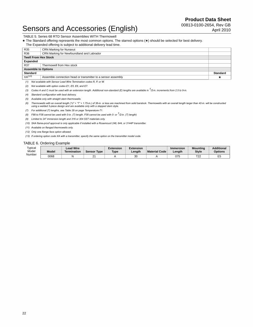
TABLE 6. Ordering Example
R35 CRN Marking for NunavutR36 CRN Marking for Newfoundland and LabradorTwell From Hex StockExpandedR37 Thermowell from Hex stockAssemble to OptionsStandard StandardXA(13) Assemble connection head or transmitter to a sensor assembly ★
(1) Not available with Sensor Lead Wire Termination codes R, P, or W.
(2) Not available with option codes E1, E5, E6, and E7.
(3) Codes A and C must be used with an extension length. Additional non-standard (E) lengths are available in 1/2-in. increments from 2.5 to 9-in.
(4) Standard configuration with best delivery.
(5) Available only with straight stem thermowells.
(6) Thermowells with an overall length (“U” + “T” + 1.75-in.) of 36-in. or less are machined from solid barstock. Thermowells with an overall length larger than 42-in. will be constructed using a welded 3-piece design and are available only with a stepped stem style.
(7) For additional (T) lengths, see Table 28 on page Temperature-71.
(8) F88 to F08 cannot be used with 0-in. (T) length. F08 cannot be used with 0- or 1/2-in. (T) length)
(9) Limited to 24” immersion length and 316 or 304 SST materials only.
(10) SAA flame-proof approval is only applicable if installed with a Rosemount 248, 644, or 3144P transmitter.
(11) Available on flanged thermowells only.
(12) Only one flange face option allowed.
(13) If ordering option code XA with a transmitter, specify the same option on the transmitter model code.
Typical Model
NumberModel
Lead Wire Termination Sensor Type
Extension Type
Extension Length Material Code
Immersion Length
Mounting Style
Additional Options
0068 N 21 A 30 A 075 T22 E5
TABLE 5. Series 68 RTD Sensor Assemblies WITH Thermowell ★ The Standard offering represents the most common options. The starred options (★) should be selected for best delivery.__The Expanded offering is subject to additional delivery lead time.

Product Data Sheet00813-0100-2654, Rev GBApril 2010 Sensors and Accessories (English)
SERIES 78 PLATINUM RTDSeries 78 sensors are intended for applications that require high accuracy, dual-elements, and/or are subjected to high temperatures. Rosemount Series 78 Platinum Resistance temperature sensors measure from –200 to 600 °C (–328 to 1112 °F). These sensors are available in capsule, general-purpose, spring-loaded, and bayonet spring-loaded designs in sensor (X) lengths from 1 to 68 inches.Table 7 shows the interchangeability of the Series 78 Pt100-385 sensors. The performance of the standard Series 78 sensor conforms to the standard set by IEC 751 Class B. Additionally, IEC-751 Class A accuracy is available as an option. For maximum system accuracy, Rosemount Inc. can provide sensor calibration. See Sensor Characterization (Calibration) Schedules– Option Code V. Rosemount Inc. also offers optional sensor-to-transmitter matching capability obtainable through the use of Callendar-Van Dusen Constants. See Option Code “V” Callendar-van Dusen Constantsand Option X8Q4: Sensor Calibrated to a Customer-Specified Temperature Range.
The wire-wound design and construction of the General-Purpose Series 78 sensor allows direct immersion in non-corrosive fluids at reasonable static pressures. For corrosive environments and in many industrial applications, these sensors are commonly used with standard thermowell assemblies.
Platinum Element and Lead Wire ConfigurationsSingle-element high-temperature sensors have four lead wires and may be used in 2-, 3-, and 4-wire signal conditioning systems.
Dual-element sensors have redundant elements to provide separate readout and control signals from a single measurement point. Dual-element sensors have three lead wires for each element and may be used with 2- or 3-wire systems. Dual-element sensors can also be wired to be used as compensation loop sensors (see Figure 8).
FIGURE 8. Wiring Configuration of a Dual-Element Sensor to Function as a Single Element Sensor with a Compensation Loop
Construction
FIGURE 9. Construction of a Platinum Wire-wound RTD
Single Element Dual-element(1)
(1) Dual-element sensors are only available on Series 68Q and 78 sensors.
Red
Red
White
White
WhiteWhite
GreenGreen
Red
Black
Lead Wires
Seal
Platinum Resistance Element
High Purity Insulator
23
Product Data Sheet00813-0100-2654, Rev GB
April 2010Sensors and Accessories (English)
24
Specifications
Performance
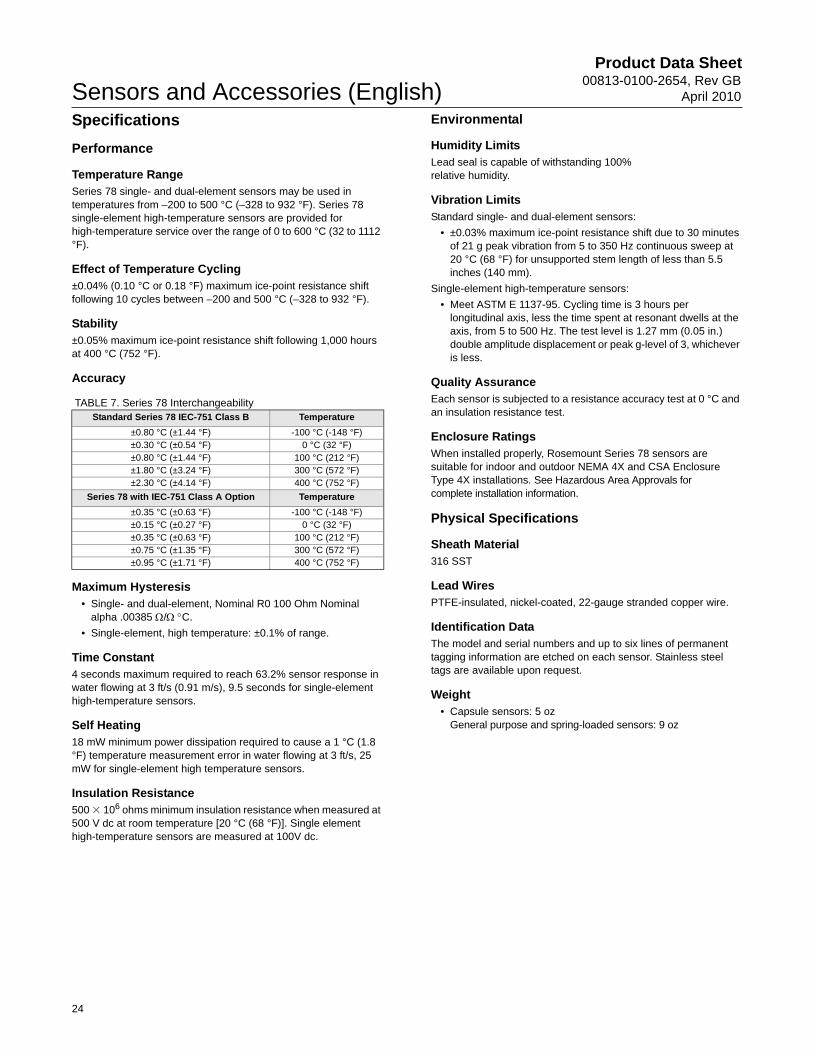
Temperature RangeSeries 78 single- and dual-element sensors may be used in temperatures from –200 to 500 °C (–328 to 932 °F). Series 78 single-element high-temperature sensors are provided for high-temperature service over the range of 0 to 600 °C (32 to 1112 °F).
Effect of Temperature Cycling±0.04% (0.10 °C or 0.18 °F) maximum ice-point resistance shift following 10 cycles between –200 and 500 °C (–328 to 932 °F).
Stability±0.05% maximum ice-point resistance shift following 1,000 hours at 400 °C (752 °F).
Accuracy
TABLE 7. Series 78 Interchangeability
Maximum Hysteresis• Single- and dual-element, Nominal R0 100 Ohm Nominal
alpha .00385 / C.
• Single-element, high temperature: ±0.1% of range.
Time Constant4 seconds maximum required to reach 63.2% sensor response in water flowing at 3 ft/s (0.91 m/s), 9.5 seconds for single-element high-temperature sensors.
Self Heating18 mW minimum power dissipation required to cause a 1 °C (1.8 °F) temperature measurement error in water flowing at 3 ft/s, 25 mW for single-element high temperature sensors.
Insulation Resistance 500 � 106 ohms minimum insulation resistance when measured at 500 V dc at room temperature [20 °C (68 °F)]. Single element high-temperature sensors are measured at 100V dc.
Environmental
Humidity LimitsLead seal is capable of withstanding 100% relative humidity.
Vibration LimitsStandard single- and dual-element sensors:
• ±0.03% maximum ice-point resistance shift due to 30 minutes of 21 g peak vibration from 5 to 350 Hz continuous sweep at 20 °C (68 °F) for unsupported stem length of less than 5.5 inches (140 mm).
Single-element high-temperature sensors:
• Meet ASTM E 1137-95. Cycling time is 3 hours per longitudinal axis, less the time spent at resonant dwells at the axis, from 5 to 500 Hz. The test level is 1.27 mm (0.05 in.) double amplitude displacement or peak g-level of 3, whichever is less.
Quality AssuranceEach sensor is subjected to a resistance accuracy test at 0 °C and an insulation resistance test.
Enclosure RatingsWhen installed properly, Rosemount Series 78 sensors are suitable for indoor and outdoor NEMA 4X and CSA Enclosure Type 4X installations. See Hazardous Area Approvals for complete installation information.
Physical Specifications
Sheath Material316 SST
Lead WiresPTFE-insulated, nickel-coated, 22-gauge stranded copper wire.
Identification DataThe model and serial numbers and up to six lines of permanent tagging information are etched on each sensor. Stainless steel tags are available upon request.
Weight • Capsule sensors: 5 oz
General purpose and spring-loaded sensors: 9 oz
Standard Series 78 IEC-751 Class B Temperature
±0.80 °C (±1.44 °F) -100 °C (-148 °F)±0.30 °C (±0.54 °F) 0 °C (32 °F)±0.80 °C (±1.44 °F) 100 °C (212 °F)±1.80 °C (±3.24 °F) 300 °C (572 °F)±2.30 °C (±4.14 °F) 400 °C (752 °F)
Series 78 with IEC-751 Class A Option Temperature
±0.35 °C (±0.63 °F) -100 °C (-148 °F)±0.15 °C (±0.27 °F) 0 °C (32 °F)±0.35 °C (±0.63 °F) 100 °C (212 °F)±0.75 °C (±1.35 °F) 300 °C (572 °F)±0.95 °C (±1.71 °F) 400 °C (752 °F)
Product Data Sheet00813-0100-2654, Rev GBApril 2010 Sensors and Accessories (English)
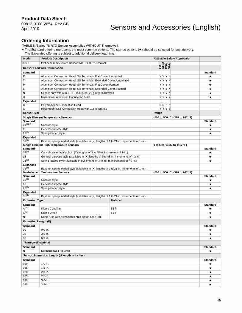
Ordering Information TABLE 8. Series 78 RTD Sensor Assemblies WITHOUT Thermowell★ The Standard offering represents the most common options. The starred options (★) should be selected for best delivery.__The Expanded offering is subject to additional delivery lead time.
Model Product Description Available Safety Approvals
0078 Platinum Temperature Sensor WITHOUT Thermowell
FM
AT
EX
CS
AS
AA
Sensor Lead Wire Termination
Standard StandardR Aluminum Connection Head, Six Terminals, Flat Cover, Unpainted Y Y Y N ★
T Aluminum Connection Head, Six Terminals, Extended Cover, Unpainted Y Y Y N ★
P Aluminum Connection Head, Six Terminals, Flat Cover, Painted Y Y Y N ★
L Aluminum Connection Head, Six Terminals, Extended Cover, Painted Y Y Y N ★
N Sensor only with 6-in. PTFE-insulated, 22-gauge lead wires Y Y Y N ★
D Rosemount Aluminum Connection head Y Y Y Y ★
ExpandedC Polypropylene Connection Head N N N NG Rosemount SST Connection Head with 1/2 in. Entries Y Y Y Y
Sensor Type Range
Single Element Temperature Sensors -200 to 500 °C (-328 to 932 °F)Standard Standard01(1)(2) Capsule style ★
11 General-purpose style ★
21(3) Spring-loaded style ★
Expanded31(4) Bayonet spring-loaded style (available in (X) lengths of 1 to 21-in, increments of 1-in.)Single Element High Temperature Sensors 0 to 600 °C (32 to 1112 °F)Standard Standard03(1) Capsule style (available in (X) lengths of 3 to 48-in, increments of 1-in.) ★
13 General-purpose style (available in (X) lengths of 3 to 48-in, increments of 1/2-in.) ★
23(3) Spring-loaded style (available in (X) lengths of 3 to 48-in, increments of 1/2-in.) ★
Expanded33(4) Bayonet spring-loaded style (available in (X) lengths of 3 to 21-in, increments of 1-in.)Dual-element Temperature Sensors -200 to 500 °C (-328 to 932 °F)Standard Standard05(1) Capsule style ★
15 General-purpose style ★
25(3) Spring-loaded style ★
Expanded35(4) Bayonet spring-loaded style (available in (X) lengths of 1 to 21-in, increments of 1-in.)
Extension Type Material
Standard StandardA(5) Nipple Coupling SST ★
C(5) Nipple Union SST ★
N None (Use with extension length option code 00) ★
Extension Length (E)
Standard Standard00 0.0 in. ★
30 3.0 in. ★
60 6.0 in. ★
Thermowell Material
Standard StandardN No thermowell required ★
Sensor/ Immersion Length (U length in inches)
Standard Standard010 1.0-in. ★
015 1.5-in. ★
020 2.0-in. ★
025 2.5-in. ★
030 3.0-in. ★
035 3.5-in. ★
25

Product Data Sheet00813-0100-2654, Rev GB
April 2010Sensors and Accessories (English)
040 4.0-in. ★
045 4.5-in. ★
050 5.0-in. ★
055 5.5-in. ★
060 6.0-in. ★
065 6.5-in. ★
070 7.0-in. ★
075 7.5-in. ★
080 8.0-in. ★
085 8.5-in. ★
090 9.0-in. ★
095 9.5-in. ★
100 10.0-in. ★
105 10.5-in. ★
110 11.0-in. ★
115 11.5-in. ★
120 12.0-in. ★
125 12.5-in. ★
130 13.0-in. ★
135 13.5-in. ★
140 14.0-in. ★
145 14.5-in. ★
150 15.0-in. ★
155 15.5-in. ★
160 16.0-in. ★
165 16.5-in. ★
170 17.0-in. ★
175 17.5-in. ★
180 18.0-in. ★
185 18.5-in. ★
190 19.0-in. ★
195 19.5-in. ★
200 20.0-in. ★
205 20.5-in. ★
210 21.0-in. ★
215 21.5-in. ★
220 22.0-in. ★
225 22.5-in. ★
230 23.0-in. ★
235 23.5-in. ★
240 24.0-in. ★
245 24.5-in. ★
250 25.0-in. ★
260 26.0-in. ★
270 27.0-in. ★
280 28.0-in. ★
290 29.0-in. ★
300 30.0-in. ★
310 31.0-in. ★
320 32.0-in. ★
330 33.0-in. ★
340 34.0-in. ★
350 35.0-in. ★
360 36.0-in. ★
370 37.0-in. ★
380 38.0-in. ★
390 39.0-in. ★
400 40.0-in. ★
TABLE 8. Series 78 RTD Sensor Assemblies WITHOUT Thermowell★ The Standard offering represents the most common options. The starred options (★) should be selected for best delivery.__The Expanded offering is subject to additional delivery lead time.
26

Product Data Sheet00813-0100-2654, Rev GBApril 2010 Sensors and Accessories (English)
410 41.0-in. ★
420 42.0-in. ★
430 43.0-in. ★
440 44.0-in. ★
450 45.0-in. ★
460 46.0-in. ★
470 47.0-in. ★
480(6) 48.0-in. ★
Options (Include with selected model number)
SensorExpandedA(7) IEC – 751 Class A SensorApproval OptionsStandard StandardE5 FM Explosion-proof approval (See Figure 26) ★
E6 CSA Explosion-proof approval (See Figure 27) ★
E7(8) SAA Flameproof approval (See Figure 30) ★
Callendar-Van Dusen ConstantsStandard StandardV1-V7 V-Callendar-van Dusen Constants ★
Calibration ScheduleStandard StandardX8 Customer-Specified Temperature Range Calibration ★
X9 Customer-Specified Single Temperature Point Calibration ★
Calibration CertificationStandard StandardQ4 Calibration Certification, Customer-Specified Temperature ★
Mounting AdaptersStandard StandardM5-M7 Mounting adapter; Sensor Compression Fitting: M5= 1/8-27 NPT, M6 = 1/4-18 NPT, M7 = 1/2-14 NPT ★
A LeadkitStandard StandardA1-A8 Twisted lead wire extension: A1 = 1.5 ft, A2 = 3.0 ft, A3 = 6.0 ft, A4 = 12 ft, A5 = 24 ft, A6 = 50 ft, A7 = 75 ft, A8 = 100 ft ★
B LeadkitStandard StandardB1-B8(9) Shielded cable lead wire extension: B1 = 1.5 ft, B2 = 3.0 ft, B3 = 6.0 ft, B4 = 12 ft, B5 = 24 ft, B6 = 50 ft, B7 = 75 ft, B8 = 100 ft ★
C LeadkitStandard StandardC1-C8(9) Armored cable lead wire extension: C1 = 1.5 ft, C2 = 3.0 ft, C3 = 6.0 ft, C4 = 12 ft, C5 = 24 ft, C6 = 50 ft, C7 = 75 ft, C8 = 100 ft ★
D LeadkitStandard StandardD1-D8(9) Armored cable lead wire extensions with electrical plug: D1 = 1.5 ft, D2 = 3.0 ft, D3 = 6.0 ft, D4 = 12 ft, D5 = 24 ft, D6 = 50 ft,
D7 = 75 ft, D8 = 100 ft★
L LeadkitStandard StandardL1-L8 Armored cable mating plugs with lead wire extension: L1 = 1.5 ft, L2 = 3.0 ft, L3 = 6.0 ft, L4 = 12 ft, L5 = 24 ft, L6 = 50 ft,
L7 = 75 ft, L8 = 100 ft★
F LeadkitStandard StandardF1(9) 4-pin bayonet connector ★
H LeadkitStandard StandardH1-H8 4-pin connector mating plugs with lead wire extension: H1 = 1.5 ft, H2 = 3.0 ft, H3 = 6.0 ft, H4 = 12 ft, H5 = 24 ft, H6 = 50 ft,
H7 = 75 ft, H8 = 100 ft★
J LeadkitStandard StandardJ1 Moisture-proof seal assembly for armored cables ★
Assemble to OptionsStandard StandardXA(10) Assemble connection head or transmitter to a sensor assembly (PTFE paste where appropriate, fully wired.) ★
TABLE 8. Series 78 RTD Sensor Assemblies WITHOUT Thermowell★ The Standard offering represents the most common options. The starred options (★) should be selected for best delivery.__The Expanded offering is subject to additional delivery lead time.
27

Product Data Sheet00813-0100-2654, Rev GB
April 2010Sensors and Accessories (English)
TABLE 9. Ordering Example
(1) Capsule style available in 1-in. increments only. See “Mounting Adapters for Series 58, 68, 78, and 183” on page Temperature-66.
(2) Must be used with Sensor Lead Wire Termination code N and is not available with assembly option XA or with approval option codes E1, E5, E6, or E7.
(3) Spring loaded sensors must be installed in a thermowell assembly to meet the requirements of explosion-proof approval option code E6.
(4) This option is not available with Sensor Lead Wire Termination codes R, P or C or approval code E1, E6, and E7.
(5) Codes A and C must be used with an extension length. Additional non-standard (E) lengths are available in 1/2-in. increments from 2.5 to 9-in.
(6) Additional lengths are available up to 68-in., increments of 1-in.
(7) The IEC 751 Class A option is not available with high-temperature sensors.
(8) SAA Flameproof approvals only applicable if installed with a Rosemount 248, 644, or 3144P transmitter.
(9) Requires Sensor lead wire termination code N
(10) If ordering option code XA with a transmitter, specify the same option on the transmitter model code.
Typical Model
NumberModel
Lead Wire Termination Sensor Type
Extension Type
Extension Length
Thermowell Material
Immersion Length
Additional Options
0078 N 21 N 00 N 045 E5
28

Product Data Sheet00813-0100-2654, Rev GBApril 2010 Sensors and Accessories (English)
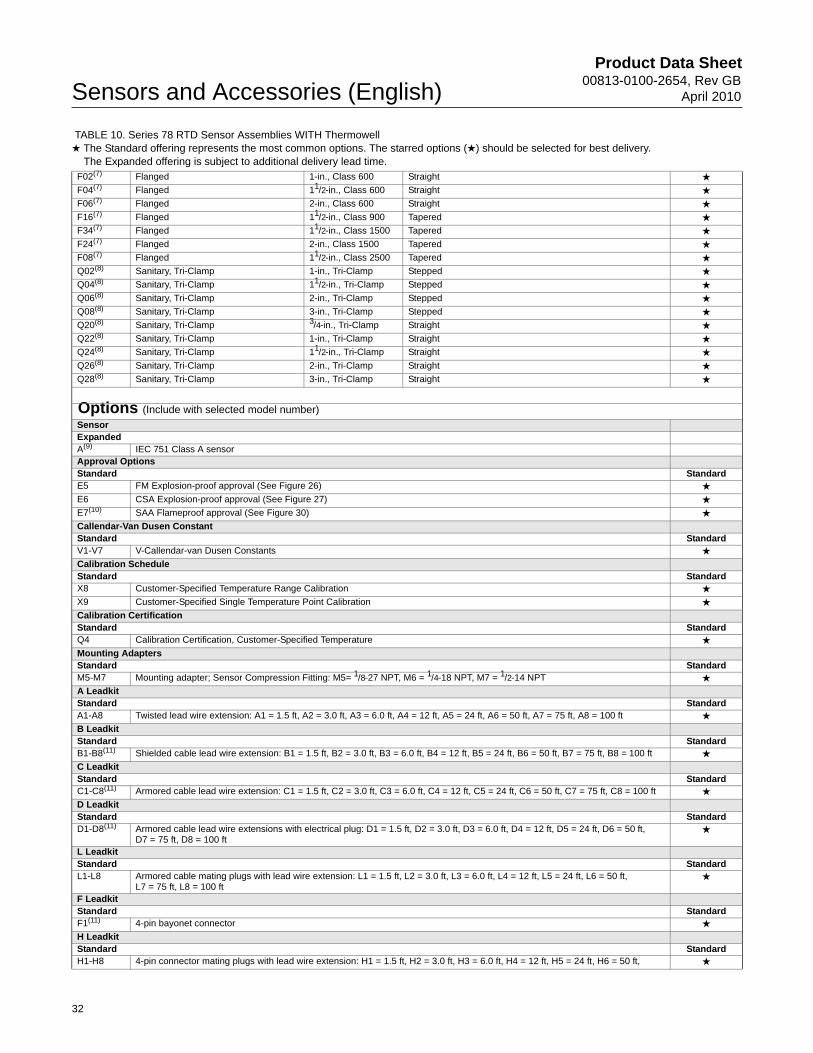
Ordering Information TABLE 10. Series 78 RTD Sensor Assemblies WITH Thermowell★ The Standard offering represents the most common options. The starred options (★) should be selected for best delivery.__The Expanded offering is subject to additional delivery lead time.
Model Product Description Available Safety Approvals
0078 Platinum Temperature Sensor WITH Thermowell
FM
AT
EX
CS
AS
AA
Sensor Lead Wire Termination
Standard StandardR Aluminum Connection Head, Six Terminals, Flat Cover, Unpainted Y Y Y N ★T Aluminum Connection Head, Six Terminals, Extended Cover, Unpainted Y Y Y N ★P Aluminum Connection Head, Six Terminals, Flat Cover, Painted Y Y Y N ★L Aluminum Connection Head, Six Terminals, Extended Cover, Painted Y Y Y N ★N Sensor only with 6-in. Teflon®-insulated, 22-gauge lead wires Y Y Y N ★D Rosemount Aluminum Connection head with 1/2- in. Entries Y Y Y Y ★ExpandedC Polypropylene Connection Head N N N NG Rosemount SST Connection Head with 1/2- in. Entries Y Y Y Y
Sensor Type Temperature
Single Element Temperature Sensors -200 to 500 °C (-328 to 932 °F)Standard Standard11 General-purpose style ★21 Spring-loaded style ★Expanded31(1)(2) Bayonet spring-loaded style (available in (X) lengths over 21-in.)Single Element High Temperature Sensors 0 to 500 °C (32 to 1112 °F)Standard Standard13 General-purpose style (available in (X) lengths of 3 to 24-in., increments of 1/2-in.) ★23 Spring-loaded style (available in (X) lengths of 3 to 24-in., increments of 1/2-in.) ★Expanded33(1)(2) Bayonet spring-loaded style (available in (X) lengths of 3 to 21-in., increments of 1-in.)Dual-element Temperature Sensors -200 to 500 °C (-328 to 932 °F)Standard Standard15 General-purpose style ★25 Spring-loaded style ★Expanded35(1)(2) Bayonet spring-loaded style (available in (X) lengths of 1 to 21-in., increments of 1-in.)
Extension Type Material
Standard StandardA(3) Nipple Coupling SST ★C(3) Nipple Union SST ★N None (Use with extension length option code 00) ★
Extension Length (E)
Standard Standard00 0.0 in. ★30 3.0 in. ★60 6.0 in. ★
Thermowell Material
Standard StandardA Type 316 SST(4) ★B Type 304 SST ★C Carbon Steel ★D 316L SST ★E 304L SST ★ExpandedF Alloy 20G Alloy 400H Alloy 600J Alloy C-276L Alloy BM 304 SST with Teflon (PTFE) coatingP Chrome Molybdenum F22R Nickel 200T TitaniumU(5) 316 SST with Tantalum Sheath
29

Product Data Sheet00813-0100-2654, Rev GB
April 2010Sensors and Accessories (English)
V 310 SSTW 321 SSTZ Chrome Molybdenum F11
Sensor/Immersion Length (U) length in inches) (L) Length in inches (T) Length in inches
Standard Standard015(6) 1.5-in. 4.0-in. 1.0-in. ★020(6) 2.0-in. 4.0-in. 0.5-in. ★025(6) 2.5-in. 4.0-in. 0.0-in. ★030 3.0-in. 6.0-in. 1.5-in. ★035 3.5-in. 6.0-in. 1.0-in. ★040 4.0-in. 6.0-in. 0.5-in. ★045 4.5-in. 6.0-in. 0.0-in. ★050 5.0-in. 9.0-in. 2.5-in. ★055 5.5-in. 9.0-in. 2.0-in. ★060 6.0-in. 9.0-in. 1.5-in. ★065 6.5-in. 9.0-in. 1.0-in. ★070 7.0-in. 9.0-in. 0.5-in. ★075 7.5-in. 9.0-in. 0.0-in. ★080 8.0-in. 12.0-in. 2.5-in. ★085 8.5-in. 12.0-in. 2.0-in. ★090 9.0-in. 12.0-in. 1.5-in. ★095 9.5-in. 12.0-in. 1.0-in. ★100 10.0-in. 12.0-in. 0.5-in. ★105 10.5-in. 12.0-in. 0.0-in. ★110 11.0-in. 15.0-in. 2.5-in. ★115 11.5-in. 15.0-in. 2.0-in. ★120 12.0-in. 15.0-in. 1.5-in. ★125 12.5-in. 15.0-in. 1.0-in. ★130 13.0-in. 15.0-in. 0.5-in. ★135 13.5-in. 15.0-in. 0.0-in. ★140 14.0-in. 18.0-in. 2.5-in. ★145 14.5-in. 18.0-in. 2.0-in. ★150 15.0-in. 18.0-in. 1.5-in. ★155 15.5-in. 18.0-in. 1.0-in. ★160 16.0-in. 18.0-in. 0.5-in. ★165 16.5-in. 18.0-in. 0.0-in. ★170 17.0-in. 21.0-in. 2.5-in. ★175 17.5-in. 21.0-in. 2.0-in. ★180 18.0-in. 21.0-in. 1.5-in. ★185 18.5-in. 21.0-in. 1.0-in. ★190 19.0-in. 21.0-in. 0.5-in. ★195 19.5-in. 21.0-in. 0.0-in. ★200 20.0-in. 24.0-in. 2.5-in. ★205 20.5-in. 24.0-in. 2.0-in. ★210 21.0-in. 24.0-in. 1.5-in. ★215 21.5-in. 24.0-in. 1.0-in. ★220 22.0-in. 24.0-in. 0.5-in. ★225 22.5-in. 24.0-in. 0.0-in. ★230 23.0-in. 27.0-in. 2.5-in. ★240 24.0-in. 27.0-in. 1.5-in. ★250 25.0-in. 27.0-in. 0.5-in. ★260 26.0-in. 30.0-in. 2.5-in. ★270 27.0-in. 30.0-in. 1.5-in. ★280 28.0-in. 30.0-in. 0.5-in. ★290 29.0-in. 33.0-in. 2.5-in. ★300 30.0-in. 33.0-in. 1.5-in. ★310 31.0-in. 33.0-in. 0.5-in. ★320 32.0-in. 36.0-in. 2.5-in. ★330 33.0-in. 36.0-in. 1.5-in. ★340 34.0-in. 36.0-in. 0.5-in. ★
TABLE 10. Series 78 RTD Sensor Assemblies WITH Thermowell★ The Standard offering represents the most common options. The starred options (★) should be selected for best delivery.__The Expanded offering is subject to additional delivery lead time.
30

Product Data Sheet00813-0100-2654, Rev GBApril 2010 Sensors and Accessories (English)
350 35.0-in. 39.0-in. 2.5-in. ★360 36.0-in. 39.0-in. 1.5-in. ★370 37.0-in. 39.0-in. 0.5-in. ★380 38.0-in. 42.0-in. 2.5-in. ★390 39.0-in. 42.0-in. 1.5-in. ★400 40.0-in. 42.0-in. 0.5-in. ★410 41.0-in. 45.0-in. 2.5-in. ★420 42.0-in. 45.0-in. 1.5-in. ★430 43.0-in. 45.0-in. 0.5-in. ★440 44.0-in. 48.0-in. 2.5-in. ★450 45.0-in. 48.0-in. 1.5-in. ★460 46.0-in. 48.0-in. 0.5-in. ★470 47.0-in. 51.0-in. 2.5-in. ★480 48.0-in. 51.0-in. 1.5-in. ★
Thermowell Style Mounting Stem
Standard StandardT20(4) Threaded 1/2-14 ANPT Stepped ★T22(4) Threaded 3/4-14 ANPT Stepped ★T24(4) Threaded 1-11.5 ANPT Stepped ★T26 Threaded 3/4-14 ANPT Tapered ★T28 Threaded 1-11.5 ANPT Tapered ★T30 Threaded 11/2-11 ANPT Tapered ★T32 Threaded 1/2-14 ANPT Straight ★T34 Threaded 3/4-14 ANPT Straight ★T36 Threaded 1-11.5 ANPT Straight ★T38 Threaded 3/4-14 ANPT Straight ★T44 Threaded 1/2-14 ANPT Tapered ★W38 Welded 3/4-in. pipe Stepped ★W40 Welded 1-in. pipe Stepped ★W42 Welded 3/4-in. pipe Tapered ★W44 Welded 1-in. pipe Tapered ★W46 Welded 11/4-in. pipe Tapered ★W48 Welded 3/4-in. pipe Straight ★W50 Welded 1-in. pipe Straight ★F10 Flanged 2-in., Class 150 Straight ★F12 Flanged 3-in., Class 150 Straight ★F52 Flanged 1-in., Class 150 Stepped ★F54 Flanged 11/2-in., Class 150 Stepped ★F56 Flanged 2-in., Class 150 Stepped ★F58 Flanged 1-in., Class 150 Tapered ★F60 Flanged 11/2-in., Class 150 Tapered ★F62 Flanged 2-in. Class 150 Tapered ★F64 Flanged 1-in., Class 150 Straight ★F66 Flanged 11/2-in., Class 150 Straight ★F70 Flanged 1-in., Class 300 Stepped ★F72 Flanged 11/2-in., Class 300 Stepped ★F74 Flanged 2-in., Class 300 Stepped ★F76 Flanged 1-in., Class 300 Tapered ★F78 Flanged 11/2-in., Class 300 Tapered ★F80 Flanged 2-in., Class 300 Tapered ★F82 Flanged 1-in., Class 300 Straight ★F84 Flanged 11/2-in., Class 300 Straight ★F86 Flanged 2-in., Class 300 Straight ★F88(7) Flanged 1-in., Class 600 Stepped ★F90(7) Flanged 11/2-in., Class 600 Stepped ★F92(7) Flanged 2-in., Class 600 Stepped ★F94(7) Flanged 1-in., Class 600 Tapered ★F96(7) Flanged 11/2-in., Class 600 Tapered ★F98(7) Flanged 2-in., Class 600 Tapered ★
TABLE 10. Series 78 RTD Sensor Assemblies WITH Thermowell★ The Standard offering represents the most common options. The starred options (★) should be selected for best delivery.__The Expanded offering is subject to additional delivery lead time.
31
Product Data Sheet00813-0100-2654, Rev GB
April 2010Sensors and Accessories (English)
F02(7) Flanged 1-in., Class 600 Straight ★F04(7) Flanged 11/2-in., Class 600 Straight ★F06(7) Flanged 2-in., Class 600 Straight ★F16(7) Flanged 11/2-in., Class 900 Tapered ★F34(7) Flanged 11/2-in., Class 1500 Tapered ★F24(7) Flanged 2-in., Class 1500 Tapered ★F08(7) Flanged 11/2-in., Class 2500 Tapered ★Q02(8) Sanitary, Tri-Clamp 1-in., Tri-Clamp Stepped ★Q04(8) Sanitary, Tri-Clamp 11/2-in., Tri-Clamp Stepped ★Q06(8) Sanitary, Tri-Clamp 2-in., Tri-Clamp Stepped ★Q08(8) Sanitary, Tri-Clamp 3-in., Tri-Clamp Stepped ★Q20(8) Sanitary, Tri-Clamp 3/4-in., Tri-Clamp Straight ★Q22(8) Sanitary, Tri-Clamp 1-in., Tri-Clamp Straight ★Q24(8) Sanitary, Tri-Clamp 11/2-in., Tri-Clamp Straight ★Q26(8) Sanitary, Tri-Clamp 2-in., Tri-Clamp Straight ★Q28(8) Sanitary, Tri-Clamp 3-in., Tri-Clamp Straight ★
Options (Include with selected model number)
SensorExpandedA(9) IEC 751 Class A sensorApproval OptionsStandard StandardE5 FM Explosion-proof approval (See Figure 26) ★E6 CSA Explosion-proof approval (See Figure 27) ★E7(10) SAA Flameproof approval (See Figure 30) ★Callendar-Van Dusen ConstantStandard StandardV1-V7 V-Callendar-van Dusen Constants ★Calibration ScheduleStandard StandardX8 Customer-Specified Temperature Range Calibration ★X9 Customer-Specified Single Temperature Point Calibration ★Calibration CertificationStandard StandardQ4 Calibration Certification, Customer-Specified Temperature ★Mounting AdaptersStandard StandardM5-M7 Mounting adapter; Sensor Compression Fitting: M5= 1/8-27 NPT, M6 = 1/4-18 NPT, M7 = 1/2-14 NPT ★A LeadkitStandard StandardA1-A8 Twisted lead wire extension: A1 = 1.5 ft, A2 = 3.0 ft, A3 = 6.0 ft, A4 = 12 ft, A5 = 24 ft, A6 = 50 ft, A7 = 75 ft, A8 = 100 ft ★B LeadkitStandard StandardB1-B8(11) Shielded cable lead wire extension: B1 = 1.5 ft, B2 = 3.0 ft, B3 = 6.0 ft, B4 = 12 ft, B5 = 24 ft, B6 = 50 ft, B7 = 75 ft, B8 = 100 ft ★C LeadkitStandard StandardC1-C8(11) Armored cable lead wire extension: C1 = 1.5 ft, C2 = 3.0 ft, C3 = 6.0 ft, C4 = 12 ft, C5 = 24 ft, C6 = 50 ft, C7 = 75 ft, C8 = 100 ft ★D LeadkitStandard StandardD1-D8(11) Armored cable lead wire extensions with electrical plug: D1 = 1.5 ft, D2 = 3.0 ft, D3 = 6.0 ft, D4 = 12 ft, D5 = 24 ft, D6 = 50 ft,
D7 = 75 ft, D8 = 100 ft★
L LeadkitStandard StandardL1-L8 Armored cable mating plugs with lead wire extension: L1 = 1.5 ft, L2 = 3.0 ft, L3 = 6.0 ft, L4 = 12 ft, L5 = 24 ft, L6 = 50 ft,
L7 = 75 ft, L8 = 100 ft★
F LeadkitStandard StandardF1(11) 4-pin bayonet connector ★H LeadkitStandard StandardH1-H8 4-pin connector mating plugs with lead wire extension: H1 = 1.5 ft, H2 = 3.0 ft, H3 = 6.0 ft, H4 = 12 ft, H5 = 24 ft, H6 = 50 ft, ★
TABLE 10. Series 78 RTD Sensor Assemblies WITH Thermowell★ The Standard offering represents the most common options. The starred options (★) should be selected for best delivery.__The Expanded offering is subject to additional delivery lead time.
32

Product Data Sheet00813-0100-2654, Rev GBApril 2010 Sensors and Accessories (English)
J LeadkitStandard StandardJ1 Moisture-proof seal assembly for armored cables ★Special External Pressure TestStandard StandardR01 Special External Pressure Test ★Material CertificationsStandard StandardQ8 Thermowell material certificate ★Surface Finish CertificationStandard StandardQ16 Surface Finish Certification ★Dye Penetration TestStandard StandardR03 Dye Penetration Test ★Thermowell Special CleaningStandard StandardR04 Thermowell Special Cleaning ★NACE ApprovalStandard StandardR05 NACE Approval ★SST Plug and ChainStandard StandardR06 SST Plug and Chain ★Full Penetration WeldStandard StandardR07(12) Full Penetration Weld ★Themowell Concentric SerrationsStandard StandardR09(12)(13) Concentric Serrations of Thermowell Flange Face ★Flat Faced FlangeStandard StandardR10 (12)(13) Flat Faced Flange ★Vent HoleStandard StandardR11 Vent Hole ★Thermowell XrayStandard StandardR12 Thermowell Xray ★Special Surface FinishStandard StandardR14 Special Surface Finish (12 RA Maximum “U” length = 22.5-in.) ★Ring Joint FlangeStandard StandardR16(12)(13) Ring Joint Flange (not available with 0-in. (T) length) ★ElectropolishStandard StandardR20 Electropolish ★Wake FrequencyStandard StandardR21 Wake Frequency - Thermowell Strength Calculation ★Internal Pressure TestStandard StandardR22 Internal Pressure Test ★Brass Plug & ChainStandard StandardR23 Brass Plug & Chain ★Canadian Registration No.ExpandedR24 CRN Marking for British ColumbiaR25 CRN Marking for AlbertaR26 CRN Marking for SaskatchewanR27 CRN Marking for ManitobaR28 CRN Marking for OntarioR29 CRN Marking for Quebec
TABLE 10. Series 78 RTD Sensor Assemblies WITH Thermowell★ The Standard offering represents the most common options. The starred options (★) should be selected for best delivery.__The Expanded offering is subject to additional delivery lead time.
33

Product Data Sheet00813-0100-2654, Rev GB
April 2010Sensors and Accessories (English)
34
TABLE 11. Ordering Example
R30 CRN Marking for New BrunswickR31 CRN Marking for Nova ScotiaR32 CRN Marking for Prince Edward IslandR33 CRN Marking for Yukon TerritoryR34 CRN Marking for Northwest TerritoryR35 CRN Marking for NunavutR36 CRN Marking for Newfoundland and LabradorTwell From Hex StockExpandedR37 Thermowell From Hex StockAssemble to OptionStandard StandardXA(2)(14) Assemble connection head or transmitter to a sensor assembly (PTFE paste where appropriate, fully wired.) ★
(1) Not available with Sensor Lead Wire Termination codes R, P or W.(2) Not available with Approval codes E1, E6, or E7.(3) Codes A and C must be used with an extension length. Additional non-standard (E) lengths are available in 1/2-in. increments from 2.5 to 9-in.(4) Standard configuration with best delivery.(5) Available only with straight stem flanged thermowells.(6) Straight or Tapered stem only.(7) F88 to F08 cannot be used with 0-in. (T) length. F08 cannot be used with 0- or 1/2-in. (T) length(8) Limited to 24” immersion length and 316 or 304 SST materials only.
(9) The IEC 751 Class A option is not available with high-temperature sensors.(10) SAA Flameproof approvals only applicable if installed with a Rosemount 248, 644, or 3144 transmitter.(11) These options are not available with Sensor Lead Wire Termination codes R, P, or W.(12) Available on flanged thermowells only.(13) Only one flange face option allowed.(14) If ordering option code XA with a transmitter, specify the same option on the transmitter model code.
Typical Model
NumberModel
Lead Wire Termination Sensor Type
Extension Type
Extension Length Material Code
Immersion Length
Mounting Style
Additional Options
0078 N 21 A 30 A 075 T22 E5
TABLE 10. Series 78 RTD Sensor Assemblies WITH Thermowell★ The Standard offering represents the most common options. The starred options (★) should be selected for best delivery.__The Expanded offering is subject to additional delivery lead time.
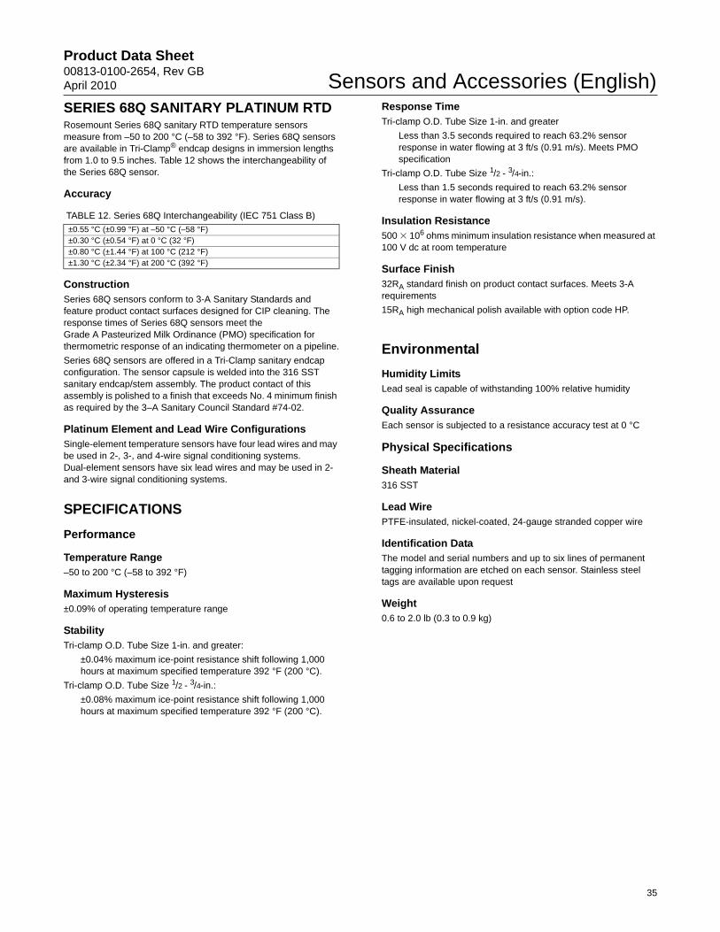
Product Data Sheet00813-0100-2654, Rev GBApril 2010 Sensors and Accessories (English)
35
SERIES 68Q SANITARY PLATINUM RTD Rosemount Series 68Q sanitary RTD temperature sensors measure from –50 to 200 °C (–58 to 392 °F). Series 68Q sensors are available in Tri-Clamp® endcap designs in immersion lengths from 1.0 to 9.5 inches. Table 12 shows the interchangeability of the Series 68Q sensor.
Accuracy
ConstructionSeries 68Q sensors conform to 3-A Sanitary Standards and feature product contact surfaces designed for CIP cleaning. The response times of Series 68Q sensors meet the Grade A Pasteurized Milk Ordinance (PMO) specification for thermometric response of an indicating thermometer on a pipeline.
Series 68Q sensors are offered in a Tri-Clamp sanitary endcap configuration. The sensor capsule is welded into the 316 SST sanitary endcap/stem assembly. The product contact of this assembly is polished to a finish that exceeds No. 4 minimum finish as required by the 3–A Sanitary Council Standard #74-02.
Platinum Element and Lead Wire ConfigurationsSingle-element temperature sensors have four lead wires and may be used in 2-, 3-, and 4-wire signal conditioning systems. Dual-element sensors have six lead wires and may be used in 2- and 3-wire signal conditioning systems.
SPECIFICATIONS
Performance
Temperature Range–50 to 200 °C (–58 to 392 °F)
Maximum Hysteresis±0.09% of operating temperature range
StabilityTri-clamp O.D. Tube Size 1-in. and greater:
±0.04% maximum ice-point resistance shift following 1,000 hours at maximum specified temperature 392 °F (200 °C).
Tri-clamp O.D. Tube Size 1/2 - 3/4-in.:
±0.08% maximum ice-point resistance shift following 1,000 hours at maximum specified temperature 392 °F (200 °C).
Response TimeTri-clamp O.D. Tube Size 1-in. and greater
Less than 3.5 seconds required to reach 63.2% sensor response in water flowing at 3 ft/s (0.91 m/s). Meets PMO specification
Tri-clamp O.D. Tube Size 1/2 - 3/4-in.:
Less than 1.5 seconds required to reach 63.2% sensor response in water flowing at 3 ft/s (0.91 m/s).
Insulation Resistance 500 � 106 ohms minimum insulation resistance when measured at 100 V dc at room temperature
Surface Finish32RA standard finish on product contact surfaces. Meets 3-A requirements
15RA high mechanical polish available with option code HP.
Environmental
Humidity LimitsLead seal is capable of withstanding 100% relative humidity
Quality AssuranceEach sensor is subjected to a resistance accuracy test at 0 °C
Physical Specifications
Sheath Material316 SST
Lead WirePTFE-insulated, nickel-coated, 24-gauge stranded copper wire
Identification DataThe model and serial numbers and up to six lines of permanent tagging information are etched on each sensor. Stainless steel tags are available upon request
Weight0.6 to 2.0 lb (0.3 to 0.9 kg)
TABLE 12. Series 68Q Interchangeability (IEC 751 Class B)
±0.55 °C (±0.99 °F) at –50 °C (–58 °F)±0.30 °C (±0.54 °F) at 0 °C (32 °F)±0.80 °C (±1.44 °F) at 100 °C (212 °F)±1.30 °C (±2.34 °F) at 200 °C (392 °F)

Product Data Sheet00813-0100-2654, Rev GB
April 2010Sensors and Accessories (English)
Dimensional Drawings
FIGURE 10. 68Q Sanitary Sensor and Polypropylene Connection Head Dimensional Drawings
68Q Sanitary Sensor with Tri-Clamp® Endcap
STEPPED STEM STRAIGHT STEM
68Q Mini General Purpose Sensor with Cable and Strain Relief
68Q Mini General Purpose Sensor with 1/2-in. NPT Threaded Adapter
68Q Mini Spring Loaded Sensor with Thermowell and Replaceable Sensor
Dimensions are in inches (millimeters)
TABLE 13. Series 68Q Spare Parts List
Mini Spring-Loaded Sanitary Replacement Sensors and Thermowells
Immersion Length (U) Replacement Sensor Part Number Replacement Thermowell Part Number
2.0 00068-4035-0020 00068-4035-10202.5 00068-4035-0025 00068-4035-10253.0 00068-4035-0030 00068-4035-1030
0.84 (21)
3.00 (76)
U
Stem
R 0.250 (6.35)R 0.250 (6.35)
0.5
Tri-ClampEndcap
½–14 ANPT
0.250 (6.35)
1.5 (6.35)
0.5 (13) 0.250 (6.35)
1/2-in 1/2-in NPT
Tri-Clamp Process Connection 1 to 3 inch O.D.tube size
U3.00 (76.2)
0.825 (20.96)
Tri-Clamp Process Connection 1/2 to 3/4 inch O.D. tube size
Lead Wire Length 2.2 (55.9) 0.25 (6.4)
0.125 (3.2)
0.375 (9.5)Vinyl Strain Relief
U
Tri-Clamp Process Connection 1/2 to 3/4 inch O.D. tube size
2.2 (55.9) 0.25 (6.4)
0.125 (3.2)
0.405 (10.3)
1/2-in. NPT / 1/2-in.
6 (152.4)
U
1/2-in. NPT / 1/2-in. NPSM
0.188 (4.8)
6 (152.4)±1.0
2.2 (55.9) ±1.25 U
36

Product Data Sheet00813-0100-2654, Rev GBApril 2010 Sensors and Accessories (English)
37
Ordering Information TABLE 14. Series 68Q Sanitary Platinum RTD Sensor Assemblies★ The Standard offering represents the most common options. The starred options (★) should be selected for best delivery.__The Expanded offering is subject to additional delivery lead time.
Model Product Description
0068Q Sanitary Platinum RTD Sensor Assembly
Sensor Lead Wire Termination
Standard Standard
P Aluminum Connection Head, Six Terminals, Flat Cover, Painted ★
L Aluminum Connection Head, Six Terminals, Extended Cover, Painted ★
N Sensor only ★
D Rosemount Aluminum Connection Head with 1/2-in. Entries ★
Expanded
C Polypropylene Connection Head
G Rosemount SST Connection Head with 1/2-in. Entries
Sensor Type Temperature
Standard Standard
11 Single Stepped Stem -50 to 200 °C (-58 to 392 °F) ★
15 Dual Stepped Stem -50 to 200 °C (-58 to 392 °F) ★
21 Single Straight Stem -50 to 200 °C (-58 to 392 °F) ★
25 Dual Straight Stem -50 to 200 °C (-58 to 392 °F) ★
30(1) (2) Mini General Purpose 6-in. lead with 1/2-in. NPT Threaded Adapter -50 to 200 °C (-58 to 392 °F) ★
31(1)(2)(3) Mini General Purpose 6-in. lead with 1/2-in. NPSM Threaded Adapter -50 to 200 °C (-58 to 392 °F) ★
32(1)(2)(3) Mini General Purpose 180-in. cable with strain relief -50 to 200 °C (-58 to 392 °F) ★
33(1)(2)(3) Mini General Purpose 300-in. cable with strain relief -50 to 200 °C (-58 to 392 °F) ★
41(4) Mini Spring Loaded with thermowell replacement sensor -50 to 200 °C (-58 to 392 °F) ★
Sensor Immersion Length (L) (inches
Standard Standard
U010 1.00 in. ★
U011 1.10 in. ★
U012 1.20 in. ★
U013 1.25 in. ★
U014 1.40 in. ★
U015 1.50 in. ★
U016 1.60 in. ★
U017 1.70 in. ★
U018 1.80 in. ★
U019 1.90 in. ★
U020 2.00 in. ★
U025 2.50 in. ★
U030 3.00 in. ★
U035 3.50 in. ★
U040(5) 4.00 in. ★
U045 4.50 in. ★
U050(5) 5.00 in. ★
U055 5.50 in. ★
U060 6.00 in. ★
U065 6.50 in. ★
U070 7.00 in. ★
U075 7.50 in. ★
U080 8.00 in. ★
U085 8.50 in. ★
U090 9.00 in. ★
U095 9.50 in. ★
Endcap Type O.D. Tube Size (inches)
Standard Standard
L050(6) Tri-Clamp 1/2 to 3/4 in. ★
L100 Tri-Clamp 1.00 in. ★
L150(5) Tri-Clamp 1.50 in. ★
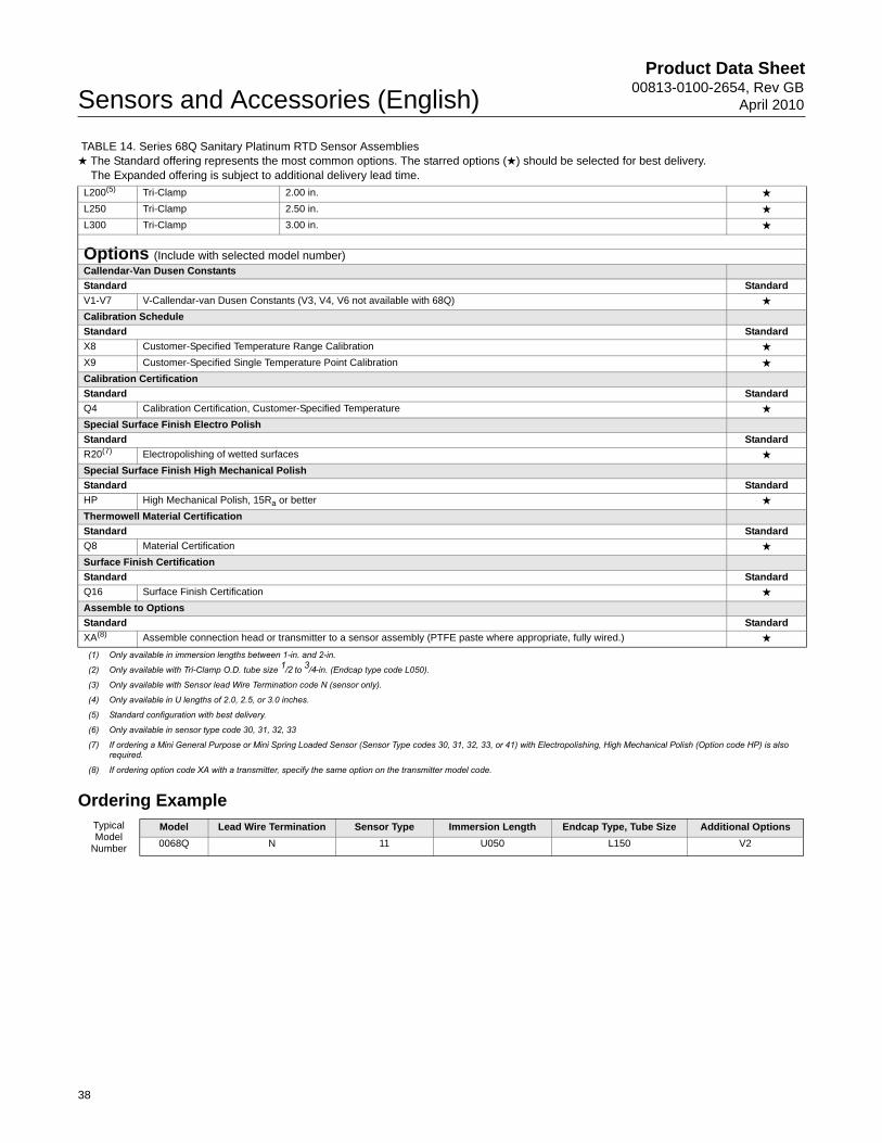
Product Data Sheet00813-0100-2654, Rev GB
April 2010Sensors and Accessories (English)
Ordering Example
L200(5) Tri-Clamp 2.00 in. ★
L250 Tri-Clamp 2.50 in. ★
L300 Tri-Clamp 3.00 in. ★
Options (Include with selected model number)Callendar-Van Dusen Constants
Standard Standard
V1-V7 V-Callendar-van Dusen Constants (V3, V4, V6 not available with 68Q) ★
Calibration Schedule
Standard Standard
X8 Customer-Specified Temperature Range Calibration ★
X9 Customer-Specified Single Temperature Point Calibration ★
Calibration Certification
Standard Standard
Q4 Calibration Certification, Customer-Specified Temperature ★
Special Surface Finish Electro Polish
Standard Standard
R20(7) Electropolishing of wetted surfaces ★
Special Surface Finish High Mechanical Polish
Standard Standard
HP High Mechanical Polish, 15Ra or better ★
Thermowell Material Certification
Standard Standard
Q8 Material Certification ★
Surface Finish Certification
Standard Standard
Q16 Surface Finish Certification ★
Assemble to Options
Standard Standard
XA(8) Assemble connection head or transmitter to a sensor assembly (PTFE paste where appropriate, fully wired.) ★
(1) Only available in immersion lengths between 1-in. and 2-in.
(2) Only available with Tri-Clamp O.D. tube size 1/2 to 3/4-in. (Endcap type code L050).
(3) Only available with Sensor lead Wire Termination code N (sensor only).
(4) Only available in U lengths of 2.0, 2.5, or 3.0 inches.
(5) Standard configuration with best delivery.
(6) Only available in sensor type code 30, 31, 32, 33
(7) If ordering a Mini General Purpose or Mini Spring Loaded Sensor (Sensor Type codes 30, 31, 32, 33, or 41) with Electropolishing, High Mechanical Polish (Option code HP) is also required.
(8) If ordering option code XA with a transmitter, specify the same option on the transmitter model code.
TABLE 14. Series 68Q Sanitary Platinum RTD Sensor Assemblies★ The Standard offering represents the most common options. The starred options (★) should be selected for best delivery.__The Expanded offering is subject to additional delivery lead time.
Typical Model
Number
Model Lead Wire Termination Sensor Type Immersion Length Endcap Type, Tube Size Additional Options
0068Q N 11 U050 L150 V2
38

Product Data Sheet00813-0100-2654, Rev GBApril 2010 Sensors and Accessories (English)
SERIES 58C PLATINUM RTDRosemount Series 58C sensors are available in 12-, 24-, 36-, and 48-inch (X) lengths and may be shortened to any desired length with an ordinary tubing cutter. This cut-to-fit feature eliminates the need to stock a large selection of sensors in many specific lengths. Table 15 shows the interchangeability of the Series 58C Sensor.
Specifications
Performance Specifications
Temperature Range–50 to 200 °C (–58 to 392 °F)
Maximum Hysteresis±0.09% of operating temperature range.
Stability±0.035% maximum ice-point resistance shift following 1,000 hours at maximum specified temperature (200 °C).
Insulation Resistance 500 � 106 ohms minimum insulation resistance when measured at 50 V dc at room temperature.
Environmental Specifications
Humidity LimitsNo permanent rear seal is installed
Quality AssuranceEach sensor is subjected to a resistance accuracy test at 0 °C and an insulation resistance test
Physical Specifications
Sheath Material316 SST
Lead WiresPTFE-insulated, nickel-coated, 24-gauge stranded copper wire
Dimensional Drawings
TABLE 15. Series 58C Interchangeability (IEC 751 Class B)
±0.55 °C (±0.99 °F) at –50 °C (–58 °F)±0.30 °C (±0.54 °F) at 0 °C (32 °F)±0.80 °C (±1.44 °F) at 100 °C (212 °F)±1.30 °C (±2.34 °F) at 200 °C (392 °F)
Series 58C Sensor
Do not cut all the way through the sensor sheath when cutting the sensor to length. Damage to the sensor wires could result. To prevent damage to the sensor wires, score the sheath considerably with a tubing cutter and gently break off the excess.
Option Code SNN Spring-Loaded Fitting 303 SST. 1/2–14 ANPT
Option Codes C01, C02, Swagelok Compression Fitting 316 SST. 1/2–14 ANPT
Dimensions are in inches (millimeters)
4 Lead Wires 6 (152) Long
Nylon Sleeve
0.25 ±0.002 (6.35 ±0.13) Diameter
0.6 (15) Max. Sensing Element
Do Not Cut or Bend Sheath within 2 (51)
X Length ±0.25 (±6)
for 0.25 (6)Diameter Sensors
2.51 (64) Max.
for 0.25 (6)Diameter Sensors
1.75 (44) Max.
39
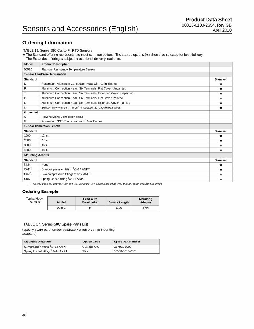
Product Data Sheet00813-0100-2654, Rev GB
April 2010Sensors and Accessories (English)
Ordering Information
Ordering Example
TABLE 17. Series 58C Spare Parts List(specify spare part number separately when ordering mounting adapters)
TABLE 16. Series 58C Cut-to-Fit RTD Sensors★ The Standard offering represents the most common options. The starred options (★) should be selected for best delivery.__The Expanded offering is subject to additional delivery lead time.
Model Product Description
0058C Platinum Resistance Temperature Sensor
Sensor Lead Wire Termination
Standard Standard
D Rosemount Aluminum Connection Head with 1/2-in. Entries ★
R Aluminum Connection Head, Six Terminals, Flat Cover, Unpainted ★
T Aluminum Connection Head, Six Terminals, Extended Cover, Unpainted ★
P Aluminum Connection Head, Six Terminals, Flat Cover, Painted ★
L Aluminum Connection Head, Six Terminals, Extended Cover, Painted ★
N Sensor only with 6-in. Teflon® -insulated, 22-gauge lead wires ★
Expanded
C Polypropylene Connection Head
G Rosemount SST Connection with 1/2-in. Entries
Sensor Immersion Length
Standard Standard
1200 12 in. ★
2400 24 in. ★
3600 36 in. ★
4800 48 in. ★
Mounting Adapter
Standard Standard
NNN None ★
C01(1) One-compression fitting 1/2–14 ANPT ★
C02(1) Two-compression fittings 1/2–14 ANPT ★
SNN Spring-loaded fitting 1/2–14 ANPT ★
(1) The only difference between C01 and C02 is that the C01 includes one fitting while the C02 option includes two fittings.
Typical Model Number Model
Lead Wire Termination Sensor Length
Mounting Adapter
0058C R 1200 SNN
Mounting Adapters Option Code Spare Part Number
Compression fitting 1/2–14 ANPT C01 and C02 C07961-0008
Spring loaded fitting 1/2–14 ANPT SNN 00058-0010-0001
40
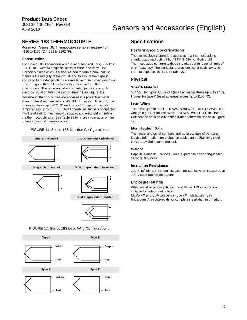
Product Data Sheet00813-0100-2654, Rev GBApril 2010 Sensors and Accessories (English)
SERIES 183 THERMOCOUPLERosemount Series 183 Thermocouple sensors measure from –180 to 1150 °C (–292 to 2102 °F).
ConstructionThe Series 183 Thermocouples are manufactured using ISA Type J, K, E, or T wire with “special limits of error” accuracy. The junction of these wires is fusion-welded to form a pure joint, to maintain the integrity of the circuit, and to ensure the highest accuracy. Grounded junctions are available for improved response time and good thermal contact with protection from the environment. The ungrounded and isolated junctions provide electrical isolation from the sensor sheath (see Figure 11).
Rosemount thermocouples are encased in a protective metal sheath. The sheath material is 304 SST for types J, E, and T, used at temperatures up to 871 °C and Inconel for type K, used at temperatures up to 1150 °C. Metallic oxide insulation is compacted into the sheath to mechanically support and electrically insulate the thermocouple wire. See Table 22 for more information on the different types of thermocouples.
FIGURE 11. Series 183 Junction Configurations
FIGURE 12. Series 183 Lead Wire Configurations
Specifications
Performance SpecificationsThe thermoelectric current relationship in a thermocouple is standardized and defined by ASTM E-230. All Series 183 Thermocouples conform to these standards with “special limits of error” accuracy. The particular characteristics of each ISA type thermocouple are outlined in Table 22.
Physical
Sheath Material304 SST for types J, E, and T (used at temperatures up to 871 °C). Inconel for type K (used at temperatures up to 1150 °C).
Lead WiresThermocouple, internal—16 AWG solid wire (max), 18 AWG solid wire (min.). External lead wires—20 AWG wire, PTFE-insulated. Color coded per lead wire configuration schematic shown in Figure 12.
Identification DataThe model and serial numbers and up to six lines of permanent tagging information are etched on each sensor. Stainless steel tags are available upon request.
Weight Capsule sensors: 5 ounces. General-purpose and spring-loaded sensors: 9 ounces.
Insulation Resistance 100 � 106 ohms minimum insulation resistance when measured at 100 V dc at room temperature.
Enclosure RatingsWhen installed properly, Rosemount Series 183 sensors are suitable for indoor and outdoor NEMA 4X and CSA Enclosure Type 4X installations. See Hazardous Area Approvals for complete installation information.
Single, Grounded Dual, Grounded, Unisolated
Single, Ungrounded Dual, Ungrounded, Unisolated
Dual, Ungrounded, Isolated
Type J Type E
Type K Type T
+
–
++
––
+
–
++
––
++
––
+ White
– Red
+ Purple
– Red
+ Yellow
– Red
+ Blue
– Red
41

Product Data Sheet00813-0100-2654, Rev GB
April 2010Sensors and Accessories (English)
Ordering Information
TABLE 18. Series 183 Thermocouple Sensor Assemblies WITHOUT Thermowell★ The Standard offering represents the most common options. The starred options (★) should be selected for best delivery.__The Expanded offering is subject to additional delivery lead time.
Model Product Description Available Safety Approvals
0183 Thermocouple Sensor WITHOUT Thermowell
FM
AT
EX
CS
A
SA
A
Sensor Lead Wire Termination
Standard Standard
R Aluminum Connection Head, Six Terminals, Flat Cover, Unpainted Y Y Y N ★
T Aluminum Connection Head, Six Terminals, Extended Cover, Unpainted Y Y Y N ★
P Aluminum Connection Head, Six Terminals, Flat Cover, Painted Y Y Y N ★
L Aluminum Connection Head, Six Terminals, Extended Cover, Painted Y Y Y N ★
N Sensor only with 6-in. Teflon®-insulated, 20-gauge lead wires Y Y Y N ★
D Rosemount Aluminum Connection Head with 1/2-in. Entries Y Y Y Y ★
Expanded
C Polypropylene Connection Head N N N N
G Rosemount SST Connection Head with 1/2-in. Entries N N N N
Sensor Type Junction
Capsule Sensor(1)(2)
Standard Standard
01(1) Single Grounded ★
02 Dual Grounded ★
03 Single Ungrounded ★
04 Dual, Unisolated Ungrounded ★
05 Dual, Isolated Ungrounded ★
General Purpose Sensors
Standard Standard
11 Single Grounded ★
12 Dual Grounded ★
13 Single Ungrounded ★
14 Dual, Unisolated Ungrounded ★
15 Dual, Isolated Ungrounded ★
Spring-Loaded Sensors(3)
Standard Standard
21 Single Grounded ★
22 Dual Grounded ★
23 Single Ungrounded ★
24 Dual, Unisolated Ungrounded ★
25 Dual, Isolated Ungrounded ★
Bayonet Spring-Loaded Sensors(4)(5) ★
Expanded
31 Single Grounded
32 Dual Grounded
33 Single Ungrounded
34 Dual, Unisolated Ungrounded
35 Dual, Isolated Ungrounded
Thermocouple Type Temperature Range
Standard Standard
J2 J 0 to 760 °C (32 to 1400 °F) ★
K2 K 0 to 1150 °C (32 to 2102 °F) ★
E2 E 0 to 871 °C (32 to 1600°F) ★
T2 T –180 to 371 °C (–292 to 700 °F) ★
Extension Type Material
Standard Standard
A(6) Nipple Coupling SST ★
C(6) Nipple Union SST ★
N None (Use with extension length option code 00) ★
42

Product Data Sheet00813-0100-2654, Rev GBApril 2010 Sensors and Accessories (English)
Extension Length (E)
Standard Standard
00 0.0 in. ★
30 3.0 in. (X) sensor length = (E) extension length + (L) thermowell length minus 0.25 in. (see Figure 4.)
★
60 6.0 in. ★
Thermowell Material
Standard Standard
N No thermowell required ★
Code Sensor/Immersion Length (U length in inches)
Standard Standard
020 2.0-in. ★
025 2.5-in. ★
030 3.0-in. ★
035 3.5-in. ★
040 4.0-in. ★
045 4.5-in. ★
050 5.0-in. ★
055 5.5-in. ★
060 6.0-in. ★
065 6.5-in. ★
070 7.0-in. ★
075 7.5-in. ★
080 8.0-in. ★
085 8.5-in. ★
090 9.0-in. ★
095 9.5-in. ★
100 10.0-in. ★
105 10.5-in. ★
110 11.0-in. ★
115 11.5-in. ★
120 12.0-in. ★
125 12.5-in. ★
130 13.0-in. ★
135 13.5-in. ★
140 14.0-in. ★
145 14.5-in. ★
150 15.0-in. ★
155 15.5-in. ★
160 16.0-in. ★
165 16.5-in. ★
170 17.0-in. ★
175 17.5-in. ★
180 18.0-in. ★
185 18.5-in. ★
190 19.0-in. ★
195 19.5-in. ★
200 20.0-in. ★
205 20.5-in. ★
210 21.0-in. ★
215 21.5-in. ★
220 22.0-in. ★
225 22.5-in. ★
230 23.0-in. ★
235 23.5-in. ★
TABLE 18. Series 183 Thermocouple Sensor Assemblies WITHOUT Thermowell★ The Standard offering represents the most common options. The starred options (★) should be selected for best delivery.__The Expanded offering is subject to additional delivery lead time.
43
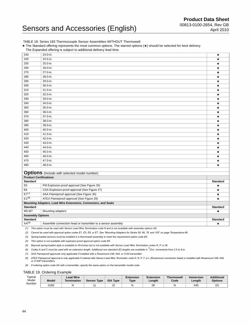
Product Data Sheet00813-0100-2654, Rev GB
April 2010Sensors and Accessories (English)
TABLE 19. Ordering Example
240 24.0-in. ★
245 24.5-in. ★
250 25.0-in. ★
260 26.0-in. ★
270 27.0-in. ★
280 28.0-in. ★
290 29.0-in. ★
300 30.0-in. ★
310 31.0-in. ★
320 32.0-in. ★
330 33.0-in. ★
340 34.0-in. ★
350 35.0-in. ★
360 36.0-in. ★
370 37.0-in. ★
380 38.0-in. ★
390 39.0-in. ★
400 40.0-in. ★
410 41.0-in. ★
420 42.0-in. ★
430 43.0-in. ★
440 44.0-in. ★
450 45.0-in. ★
460 46.0-in. ★
470 47.0-in. ★
480 48.0-in. ★
Options (Include with selected model number)Product Certifications
Standard Standard
E5 FM Explosion-proof approval (See Figure 26) ★
E6 CSA Explosion-proof approval (See Figure 27) ★
E7(7) SAA Flameproof approval (See Figure 30) ★
E1(8) ATEX Flameproof approval (See Figure 29) ★
Mounting Adapters, Lead Wire Extensions, Connectors, and Seals
Standard Standard
M5-M7 Mounting adapters ★
Assembly Options
Standard Standard
XA(9) Assemble connection head or transmitter to a sensor assembly ★
(1) This option must be used with Sensor Lead Wire Termination code N and is not available with assembly options XA.
(2) Cannot be used with approval option codes E1, E5, E6, or E7. See “Mounting Adapters for Series 58, 68, 78, and 183” on page Temperature-66.
(3) Spring-loaded sensors must be installed in a thermowell assembly to meet the requirement option code E6.
(4) This option is not available with explosion-proof approval option code E6.
(5) Bayonet spring-loaded style is available to 45-inches but is not available with Sensor Lead Wire Termination codes R, P, or W.
(6) Codes A and C must be used with an extension length. Additional non-standard (E) lengths are available in 1/2-in. increments from 2.5 to 9-in.
(7) SAA Flameproof approvals only applicable if installed with a Rosemount 248, 644, or 3144 transmitter.
(8) ATEX Flameproof approval is only applicable if ordered with Sensor Lead Wire Terminator code D, R, P. T. or L (Rosemount connection head) or installed with Rosemount 248, 644, or 3144P transmitters.
(9) If ordering option code XA with a transmitter, specify the same option on the transmitter model code.
Typical Model
NumberModel
Lead Wire Termination Sensor Type ISA Type
Extension Type
Extension Length
Thermowell Code
Immersion Length
Additional Options
0183 N 11 J2 N 00 N 045 E5
TABLE 18. Series 183 Thermocouple Sensor Assemblies WITHOUT Thermowell★ The Standard offering represents the most common options. The starred options (★) should be selected for best delivery.__The Expanded offering is subject to additional delivery lead time.
44
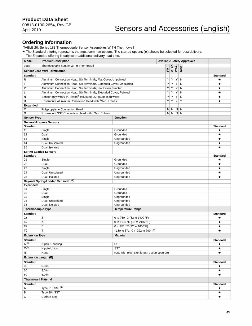
Product Data Sheet00813-0100-2654, Rev GBApril 2010 Sensors and Accessories (English)
Ordering Information TABLE 20. Series 183 Thermocouple Sensor Assemblies WITH Thermowell★ The Standard offering represents the most common options. The starred options (★) should be selected for best delivery.__The Expanded offering is subject to additional delivery lead time.
Model Product Description Available Safety Approvals
0183 Thermocouple Sensor WITH Thermowell
FM
AT
EX
CS
A
SA
A
Sensor Lead Wire Termination
Standard StandardR Aluminum Connection Head, Six Terminals, Flat Cover, Unpainted Y Y Y N ★
T Aluminum Connection Head, Six Terminals, Extended Cover, Unpainted Y Y Y N ★
P Aluminum Connection Head, Six Terminals, Flat Cover, Painted Y Y Y N ★
L Aluminum Connection Head, Six Terminals, Extended Cover, Painted Y Y Y N ★
N Sensor only with 6-in. Teflon®-insulated, 22-gauge lead wires Y Y Y N ★
D Rosemount Aluminum Connection Head with 1/2-in. Entries Y Y Y Y ★
ExpandedC Polypropylene Connection Head N N N NG Rosemount SST Connection Head with 1/2-in. Entries N N N N
Sensor Type Junction
General-Purpose SensorsStandard Standard11 Single Grounded ★
12 Dual Grounded ★
13 Single Ungrounded ★
14 Dual, Unisolated Ungrounded ★
15 Dual, Isolated ★
Spring-Loaded SensorsStandard Standard21 Single Grounded ★
22 Dual Grounded ★
23 Single Ungrounded ★
24 Dual, Unisolated Ungrounded ★
25 Dual, Isolated Ungrounded ★
Bayonet Spring-Loaded Sensors(1)(2)
Expanded31 Single Grounded32 Dual Grounded33 Single Ungrounded34 Dual, Unisolated Ungrounded35 Dual, Isolated Ungrounded
Thermocouple Type Temperature Range
Standard StandardJ2 J 0 to 760 °C (32 to 1400 °F) ★
K2 K 0 to 1150 °C (32 to 2102 °F) ★
E2 E 0 to 871 °C (32 to 1600°F) ★
T2 T –180 to 371 °C (–292 to 700 °F) ★
Extension Type Material
Standard StandardA(3) Nipple Coupling SST ★
C(3) Nipple Union SST ★
N None (Use with extension length option code 00) ★
Extension Length (E)
Standard Standard00 0.0 in. ★
30 3.0 in. ★
60 6.0 in. ★
Thermowell Material
Standard StandardA Type 316 SST(4) ★
B Type 304 SST ★
C Carbon Steel ★
45

Product Data Sheet00813-0100-2654, Rev GB
April 2010Sensors and Accessories (English)
D 316L SST ★
E 304L SSTExpandedF Alloy 20G Alloy 400H Alloy 600J Alloy C-276L Alloy BM 304 SST with Teflon (PTFE) coatingP Chrome Molybdenum F22R Nickel 200T TitaniumU(5) 316 SST with Tantalum SheathV 310 SSTW 321 SSTZ Chrome Molybdenum F11
Sensor/Immersion Length (U(6) length in inches) (L) Length in Inches T(7) Length in Inches
Standard Standard015(8) 1.5-in. 4.0-in. 1.0-in. ★
020(6) 2.0-in. 4.0-in. 0.5-in. ★
025(6) 2.5-in. 4.0-in. 0.0-in. ★
030 3.0-in. 6.0-in. 1.5-in. ★
035 3.5-in. 6.0-in. 1.0-in. ★
040 4.0-in. 6.0-in. 0.5-in. ★
045 4.5-in. 6.0-in. 0.0-in. ★
050 5.0-in. 9.0-in. 2.5-in. ★
055 5.5-in. 9.0-in. 2.0-in. ★
060 6.0-in. 9.0-in. 1.5-in. ★
065 6.5-in. 9.0-in. 1.0-in. ★
070 7.0-in. 9.0-in. 0.5-in. ★
075 7.5-in. 9.0-in. 0.0-in. ★
080 8.0-in. 12.0-in. 2.5-in. ★
085 8.5-in. 12.0-in. 2.0-in. ★
090 9.0-in. 12.0-in. 1.5-in. ★
095 9.5-in. 12.0-in. 1.0-in. ★
100 10.0-in. 12.0-in. 0.5-in. ★
105 10.5-in. 12.0-in. 0.0-in. ★
110 11.0-in. 15.0-in. 2.5-in. ★
115 11.5-in. 15.0-in. 2.0-in. ★
120 12.0-in. 15.0-in. 1.5-in. ★
125 12.5-in. 15.0-in. 1.0-in. ★
130 13.0-in. 15.0-in. 0.5-in. ★
135 13.5-in. 15.0-in. 0.0-in. ★
140 14.0-in. 18.0-in. 2.5-in. ★
145 14.5-in. 18.0-in. 2.0-in. ★
150 15.0-in. 18.0-in. 1.5-in. ★
155 15.5-in. 18.0-in. 1.0-in. ★
160 16.0-in. 18.0-in. 0.5-in. ★
165 16.5-in. 18.0-in. 0.0-in. ★
170 17.0-in. 21.0-in. 2.5-in. ★
175 17.5-in. 21.0-in. 2.0-in. ★
180 18.0-in. 21.0-in. 1.5-in. ★
185 18.5-in. 21.0-in. 1.0-in. ★
190 19.0-in. 21.0-in. 0.5-in. ★
195 19.5-in. 21.0-in. 0.0-in. ★
200 20.0-in. 24.0-in. 2.5-in. ★
205 20.5-in. 24.0-in. 2.0-in. ★
210 21.0-in. 24.0-in. 1.5-in. ★
215 21.5-in. 24.0-in. 1.0-in. ★
TABLE 20. Series 183 Thermocouple Sensor Assemblies WITH Thermowell★ The Standard offering represents the most common options. The starred options (★) should be selected for best delivery.__The Expanded offering is subject to additional delivery lead time.
46
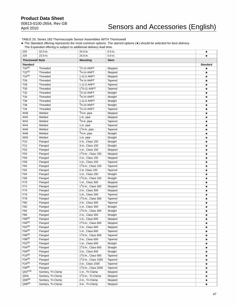
Product Data Sheet00813-0100-2654, Rev GBApril 2010 Sensors and Accessories (English)
220 22.0-in. 24.0-in. 0.5-in. ★
225 22.5-in. 24.0-in. 0.0-in. ★
Thermowell Style Mounting Stem
Standard StandardT20(4) Threaded 1/2-14 ANPT Stepped ★
T22(4) Threaded 3/4-14 ANPT Stepped ★
T24(4) Threaded 1-11.5 ANPT Stepped ★
T26 Threaded 3/4-14 ANPT Tapered ★
T28 Threaded 1-11.5 ANPT Tapered ★
T30 Threaded 11/2-11 ANPT Tapered ★
T32 Threaded 1/2-14 ANPT Straight ★
T34 Threaded 3/4-14 ANPT Straight ★
T36 Threaded 1-11.5 ANPT Straight ★
T38 Threaded 3/4-14 ANPT Straight ★
T44 Threaded 1/2-14 ANPT Tapered ★
W38 Welded 3/4-in. pipe Stepped ★
W40 Welded 1-in. pipe Stepped ★
W42 Welded 3/4-in. pipe Tapered ★
W44 Welded 1-in. pipe Tapered ★
W46 Welded 11/4-in. pipe Tapered ★
W48 Welded 3/4-in. pipe Straight ★
W50 Welded 1-in. pipe Straight ★
F10 Flanged 2-in., Class 150 Straight ★
F12 Flanged 3-in., Class 150 Straight ★
F52 Flanged 1-in., Class 150 Stepped ★
F54 Flanged 11/2-in., Class 150 Stepped ★
F56 Flanged 2-in., Class 150 Stepped ★
F58 Flanged 1-in., Class 150 Tapered ★
F60 Flanged 11/2-in., Class 150 Tapered ★
F62 Flanged 2-in. Class 150 Tapered ★
F64 Flanged 1-in., Class 150 Straight ★
F66 Flanged 11/2-in., Class 150 Straight ★
F70 Flanged 1-in., Class 300 Stepped ★
F72 Flanged 11/2-in., Class 300 Stepped ★
F74 Flanged 2-in., Class 300 Stepped ★
F76 Flanged 1-in., Class 300 Tapered ★
F78 Flanged 11/2-in., Class 300 Tapered ★
F80 Flanged 2-in., Class 300 Tapered ★
F82 Flanged 1-in., Class 300 Straight ★
F84 Flanged 11/2-in., Class 300 Straight ★
F86 Flanged 2-in., Class 300 Straight ★
F88(9) Flanged 1-in., Class 600 Stepped ★
F90(9) Flanged 11/2-in., Class 600 Stepped ★
F92(9) Flanged 2-in., Class 600 Stepped ★
F94(9) Flanged 1-in., Class 600 Tapered ★
F96(9) Flanged 11/2-in., Class 600 Tapered ★
F98(9) Flanged 2-in., Class 600 Tapered ★
F02(9) Flanged 1-in., Class 600 Straight ★
F04(9) Flanged 11/2-in., Class 600 Straight ★
F06(9) Flanged 2-in., Class 600 Straight ★
F16(9) Flanged 11/2-in., Class 900 Tapered ★
F34(9) Flanged 11/2-in., Class 1500 Tapered ★
F24(9) Flanged 2-in., Class 1500 Tapered ★
F08(9) Flanged 11/2-in., Class 2500 Tapered ★
Q02(10) Sanitary, Tri-Clamp 1-in., Tri-Clamp Stepped ★
Q04c Sanitary, Tri-Clamp 11/2-in., Tri-Clamp Stepped ★
Q06(9) Sanitary, Tri-Clamp 2-in., Tri-Clamp Stepped ★
Q08(9) Sanitary, Tri-Clamp 3-in., Tri-Clamp Stepped ★
TABLE 20. Series 183 Thermocouple Sensor Assemblies WITH Thermowell★ The Standard offering represents the most common options. The starred options (★) should be selected for best delivery.__The Expanded offering is subject to additional delivery lead time.
47

Product Data Sheet00813-0100-2654, Rev GB
April 2010Sensors and Accessories (English)
Q20(9) Sanitary, Tri-Clamp 3/4-in., Tri-Clamp Straight ★
Q22(9) Sanitary, Tri-Clamp 1-in., Tri-Clamp Straight ★
Q24(9) Sanitary, Tri-Clamp 11/2-in., Tri-Clamp Straight ★
Q26(9) Sanitary, Tri-Clamp 2-in., Tri-Clamp Straight ★
Q28(9) Sanitary, Tri-Clamp 3-in., Tri-Clamp Straight ★
Options (Include with selected model number)Product CertificationsStandard StandardE5 FM Explosion-proof approval (See Figure 26) ★
E6 CSA Explosion-proof approval (See Figure 27) ★
E7(11) SAA Flameproof approval (See Figure 30) ★
Mounting AdaptersStandard StandardM5-M7 Mounting adapter: Sensor Compression Fitting: M5 = 1/8-27 NPT, M6 = 1/4-18 NPT, M7 = 1/2-14 NPT ★
Special External Pressure TestStandard StandardR01 Special External Pressure Test ★
Material CertificationStandard StandardQ8 Material Certification ★
Dye Penetration TestStandard StandardR03 Dye Penetration Test ★
Thermowell Special CleaningStandard StandardR04 Thermowell Special Cleaning ★
NACE ApprovalStandard StandardR05 NACE Approval ★
SST Plug and ChainStandard StandardR06 SST Plug and Chain ★
Full Penetration WeldStandard StandardR07(12) Full Penetration Weld ★
Thermowell Concentric SerrationsStandard StandardR09(12)(13) Concentric Serrations of Thermowell Flange Face ★
Flat Faced FlangeStandard StandardR10 (11)(12) Flat Faced Flange ★
Vent HoleStandard StandardR11 Vent Hole ★
Thermowell XrayStandard StandardR12 Thermowell Xray ★
Special Surface FinishStandard StandardR14 Special Surface Finish (12 Ra Maximum “U” length = 22.5-in.) ★
Ring Joint FlangeStandard StandardR16(11)(12) Ring joint flange (Not available with 0-in. (T) length) ★
ElectropolishStandard StandardR20 Electropolish ★
Wake FrequencyStandard StandardR21 Wake Frequency-Thermowell Strength Calculation ★
TABLE 20. Series 183 Thermocouple Sensor Assemblies WITH Thermowell★ The Standard offering represents the most common options. The starred options (★) should be selected for best delivery.__The Expanded offering is subject to additional delivery lead time.
48

Product Data Sheet00813-0100-2654, Rev GBApril 2010 Sensors and Accessories (English)
TABLE 21. Ordering Example
Internal Pressure TestStandard StandardR22 Internal Pressure Test ★
Brass Plug & ChainStandard StandardR23 Brass Plug & Chain ★
Canadian Registration No.ExpandedR24 CRN Marking for British ColumbiaR25 CRN Marking for AlbertaR26 CRN Marking for SaskatchewanR27 CRN Marking for ManitobaR28 CRN Marking for OntarioR29 CRN Marking for QuebecR30 CRN Marking for New BrunswickR31 CRN Marking for Nova ScotiaR32 CRN Marking for Prince Edward IslandR33 CRN Marking for Yukon TerritoryR34 CRN Marking for Northwest TerritoryR35 CRN Marking for NunavutR36 CRN Marking for Newfoundland and LabradorTwell From Hex StockExpandedR37 Thermowell from Hex stockAssemble to OptionsStandard StandardXA(14) Assemble connection head or transmitter to a sensor assembly ★
(1) This option is not available with explosion-proof approval option codes E1, E5, E6, or E7.(2) Bayonet spring-loaded style available to 45 inches. Codes 31 - 35 are not available with Sensor Lead Wire Termination codes R or P.(3) Codes A and C must be used with an extension length. Additional non-standard (E) lengths are available in 1/2-in. increments from 2.5 to 9-in.(4) Standard configuration with best delivery.(5) Available only with straight stem thermowells.(6) Thermowells with an overall length (“U” + “T” + 1.75-in.) of 36-in. or less are machined from solid barstock. Thermowells with an overall length larger than 42-in. will be constructed
using a welded 3-piece design and are available only with a stepped stem style.
(7) For additional (T) lengths, see Table 28 on page Temperature-71.(8) Straight or Tapered stem thermowells only.(9) Cannot be used with 0-in. (T) length. F08 cannot be used with 0- or 1/2-in. (T) length(10) Limited to 24” immersion length and 316 or 304 SST materials only.(11) SAA Flameproof approvals only applicable if installed with a Rosemount 248, 644, or 3144P transmitter.(12) Available on flanged thermowells only.(13) Only one flange face option allowed.(14) If ordering option code XA with a transmitter, specify the same option on the transmitter model code.
Typical Model
NumberModel
Lead Wire Termination
Sensor Type ISA Type
Extension Type
Extension Length
Material Code
Immersion Length
Mounting Style
Additional Options
0183 N 21 J2 A 30 A 075 T22 E5
TABLE 20. Series 183 Thermocouple Sensor Assemblies WITH Thermowell★ The Standard offering represents the most common options. The starred options (★) should be selected for best delivery.__The Expanded offering is subject to additional delivery lead time.
49
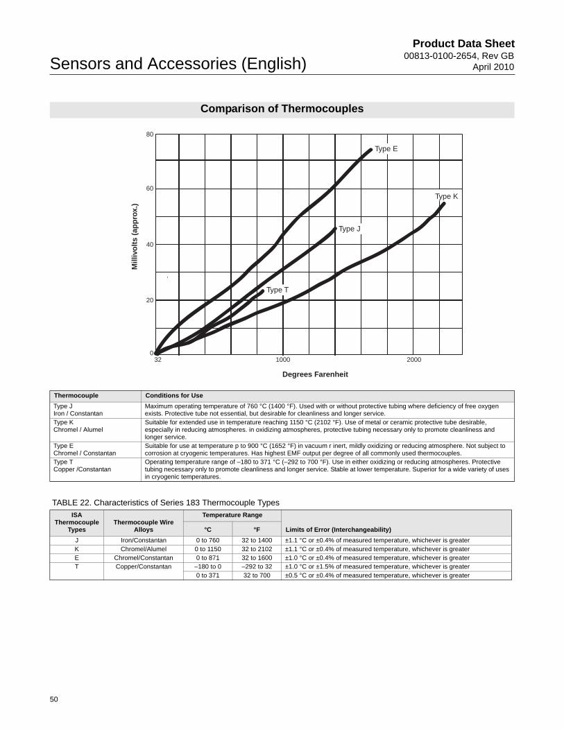
Product Data Sheet00813-0100-2654, Rev GB
April 2010Sensors and Accessories (English)
Comparison of Thermocouples
Thermocouple Conditions for Use
Type JIron / Constantan
Maximum operating temperature of 760 °C (1400 °F). Used with or without protective tubing where deficiency of free oxygen exists. Protective tube not essential, but desirable for cleanliness and longer service.
Type KChromel / Alumel
Suitable for extended use in temperature reaching 1150 °C (2102 °F). Use of metal or ceramic protective tube desirable, especially in reducing atmospheres. in oxidizing atmospheres, protective tubing necessary only to promote cleanliness and longer service.
Type EChromel / Constantan
Suitable for use at temperature p to 900 °C (1652 °F) in vacuum r inert, mildly oxidizing or reducing atmosphere. Not subject to corrosion at cryogenic temperatures. Has highest EMF output per degree of all commonly used thermocouples.
Type TCopper /Constantan
Operating temperature range of –180 to 371 °C (–292 to 700 °F). Use in either oxidizing or reducing atmospheres. Protective tubing necessary only to promote cleanliness and longer service. Stable at lower temperature. Superior for a wide variety of uses in cryogenic temperatures.
32 1000 2000
Degrees Farenheit
0
20
40
60
80M
illiv
olt
s (a
pp
rox.
)
Type E
Type J
Type T
Type KType K
TABLE 22. Characteristics of Series 183 Thermocouple Types
ISA Thermocouple
TypesThermocouple Wire
Alloys
Temperature Range
Limits of Error (Interchangeability)°C °F
J Iron/Constantan 0 to 760 32 to 1400 ±1.1 °C or ±0.4% of measured temperature, whichever is greaterK Chromel/Alumel 0 to 1150 32 to 2102 ±1.1 °C or ±0.4% of measured temperature, whichever is greaterE Chromel/Constantan 0 to 871 32 to 1600 ±1.0 °C or ±0.4% of measured temperature, whichever is greaterT Copper/Constantan –180 to 0 –292 to 32 ±1.0 °C or ±1.5% of measured temperature, whichever is greater
0 to 371 32 to 700 ±0.5 °C or ±0.4% of measured temperature, whichever is greater
50

Product Data Sheet00813-0100-2654, Rev GBApril 2010 Sensors and Accessories (English)
Calibration
CALIBRATION OPTIONSSensor calibration may be required for input to quality systems, or for control system enhancement. More frequently, it is used to improve the overall temperature measurement performance by matching the sensor to a temperature transmitter. Transmitter-Sensor matching is available for RTD sensors used with Rosemount 644, 3144P, and 3244MV temperature transmitters where the inherent stability and repeatability of the RTD technology is well established.
Transmitter-Sensor Matching Using Callendar-Van Dusen ConstantsSignificant temperature measurement accuracy improvement can be attained using a temperature sensor that is matched to a temperature transmitter. This matching process entails teaching the temperature transmitter the relationship between resistance and temperature for a specific RTD sensor. This relationship, approximated by the Callendar-Van Dusen equation, described as:
Rt = Ro + Ro[t –(0.01t – 1)(0.01t) – (0.01t – 1)(0.01t)3], where:
The exact values for R0, – known as Callendar-Van Dusen (CVD) constants – are specific to each RTD sensor, and are established by testing each individual sensor at various temperatures.
The calibration temperature values using the CVD equation are divided into two major temperature areas: above 0 °C and below 0 °C. The calibration for the temperature range between 0 and 660 °C is obtained from the following formula:
Note that this is a modification of the fourth-order CVD equation where � = 0 for temperatures greater than 0 °C. Since this modified equation is a second-order degree equation, at least three distinct temperature values are needed in order to curve fit the behavior of the RTD. For the temperature range from 0 to 100 °C only these two end points are used, and an approximation is made to render the constants.
Once the sensor-specific constants are entered, the transmitter uses them to generate a custom curve to best describe the relationship between resistance and temperature for the particular sensor and transmitter system. Matching a Series 68 or 78 RTD sensor to a 644, 3144P, and 3244MV transmitter typically results in a 3- or 4-fold improvement in temperature measurement accuracy for the total system. This substantial system accuracy improvement is realized as a result of the transmitter’s ability to use the sensor’s actual resistance-vs.-temperature curve instead of an ideal curve.
An example of the benefits of using the sensor matching capability of a Rosemount 3144P Temperature transmitter along with a matched Series 68 RTD sensor are shown in Typical Transmitter-Sensor Matching Uncertainty Improvements.
Calibration UncertaintyCalibration uncertainties of the lab are equal to or better than 1/10 IEC 751 Class B interchangeability:
Rt = Resistance (ohms) at Temperature t (°C)
Ro = Sensor-Specific Constant (Resistance at t = 0 °C)
=Sensor-Specific Constant
=Sensor-Specific Constant
=Sensor-Specific Constant (0 at t > 0 °C, 0.11 at t < 0°C)
Rt R0 1 � t �–t
100--------- t
100--------- 1– +
=
Uncertainty 0.03 0.0005 t+=
t absolute value of temperature in °C=
51
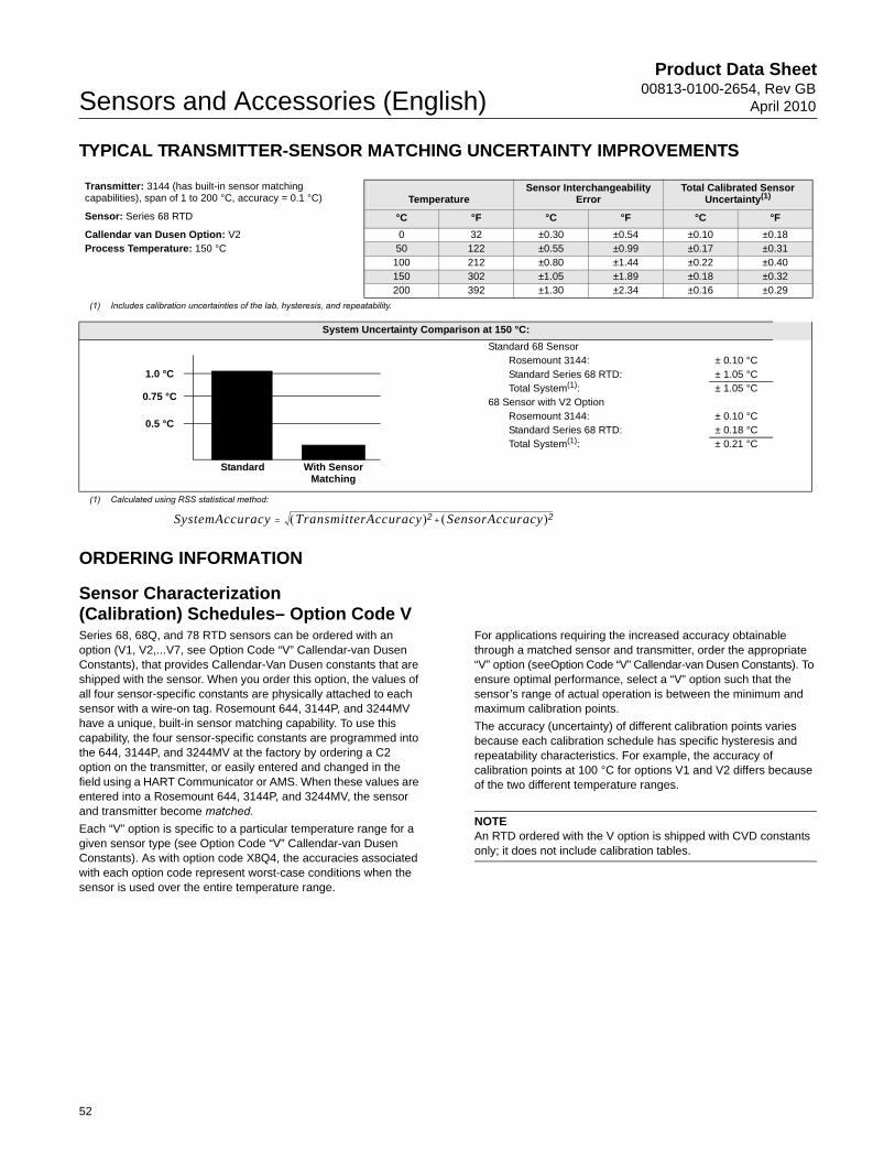
Product Data Sheet00813-0100-2654, Rev GB
April 2010Sensors and Accessories (English)
TYPICAL TRANSMITTER-SENSOR MATCHING UNCERTAINTY IMPROVEMENTS
ORDERING INFORMATION
Sensor Characterization(Calibration) Schedules– Option Code VSeries 68, 68Q, and 78 RTD sensors can be ordered with an option (V1, V2,...V7, see Option Code “V” Callendar-van Dusen Constants), that provides Callendar-Van Dusen constants that are shipped with the sensor. When you order this option, the values of all four sensor-specific constants are physically attached to each sensor with a wire-on tag. Rosemount 644, 3144P, and 3244MV have a unique, built-in sensor matching capability. To use this capability, the four sensor-specific constants are programmed into the 644, 3144P, and 3244MV at the factory by ordering a C2 option on the transmitter, or easily entered and changed in the field using a HART Communicator or AMS. When these values are entered into a Rosemount 644, 3144P, and 3244MV, the sensor and transmitter become matched.Each “V” option is specific to a particular temperature range for a given sensor type (see Option Code “V” Callendar-van Dusen Constants). As with option code X8Q4, the accuracies associated with each option code represent worst-case conditions when the sensor is used over the entire temperature range.
For applications requiring the increased accuracy obtainable through a matched sensor and transmitter, order the appropriate “V” option (seeOption Code “V” Callendar-van Dusen Constants). To ensure optimal performance, select a “V” option such that the sensor’s range of actual operation is between the minimum and maximum calibration points.
The accuracy (uncertainty) of different calibration points varies because each calibration schedule has specific hysteresis and repeatability characteristics. For example, the accuracy of calibration points at 100 °C for options V1 and V2 differs because of the two different temperature ranges.
NOTEAn RTD ordered with the V option is shipped with CVD constants only; it does not include calibration tables.
Transmitter: 3144 (has built-in sensor matching capabilities), span of 1 to 200 °C, accuracy = 0.1 °C) Temperature
Sensor Interchangeability Error
Total Calibrated Sensor Uncertainty(1)
Sensor: Series 68 RTD °C °F °C °F °C °F
Callendar van Dusen Option: V2 0 32 ±0.30 ±0.54 ±0.10 ±0.18Process Temperature: 150 °C 50 122 ±0.55 ±0.99 ±0.17 ±0.31
100 212 ±0.80 ±1.44 ±0.22 ±0.40150 302 ±1.05 ±1.89 ±0.18 ±0.32200 392 ±1.30 ±2.34 ±0.16 ±0.29
(1) Includes calibration uncertainties of the lab, hysteresis, and repeatability.
System Uncertainty Comparison at 150 °C:
Standard 68 SensorRosemount 3144: ± 0.10 °CStandard Series 68 RTD: ± 1.05 °CTotal System(1): ± 1.05 °C
68 Sensor with V2 OptionRosemount 3144: ± 0.10 °CStandard Series 68 RTD: ± 0.18 °CTotal System(1): ± 0.21 °C
(1) Calculated using RSS statistical method:
1.05 °C
0.22 °C
1.0 °C
0.75 °C
0.5 °C
Standard With Sensor Matching
SystemAccuracy TransmitterAccuracy 2 SensorAccuracy 2+=
52
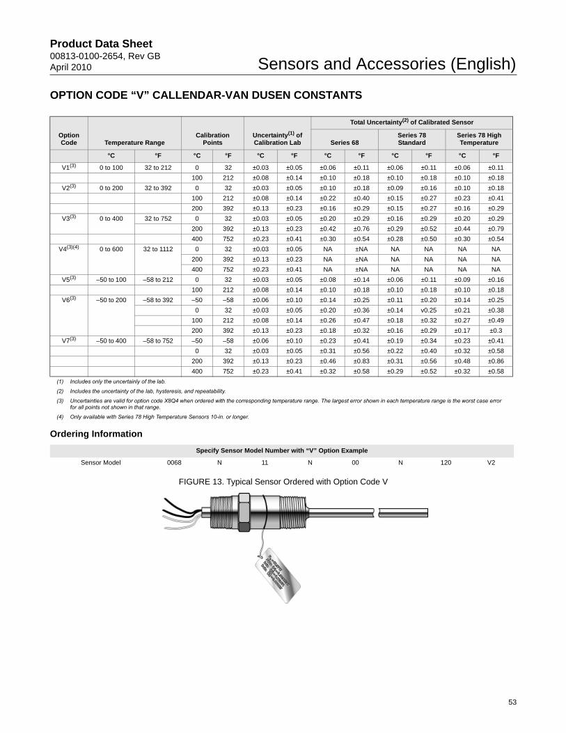
Product Data Sheet00813-0100-2654, Rev GBApril 2010 Sensors and Accessories (English)
OPTION CODE “V” CALLENDAR-VAN DUSEN CONSTANTS
Ordering Information
FIGURE 13. Typical Sensor Ordered with Option Code V
Option Code Temperature Range
Calibration Points
Uncertainty(1) of Calibration Lab
Total Uncertainty(2) of Calibrated Sensor
Series 68Series 78 Standard
Series 78 High Temperature
°C °F °C °F °C °F °C °F °C °F °C °F
V1(3) 0 to 100 32 to 212 0 32 ±0.03 ±0.05 ±0.06 ±0.11 ±0.06 ±0.11 ±0.06 ±0.11
100 212 ±0.08 ±0.14 ±0.10 ±0.18 ±0.10 ±0.18 ±0.10 ±0.18
V2(3) 0 to 200 32 to 392 0 32 ±0.03 ±0.05 ±0.10 ±0.18 ±0.09 ±0.16 ±0.10 ±0.18
100 212 ±0.08 ±0.14 ±0.22 ±0.40 ±0.15 ±0.27 ±0.23 ±0.41
200 392 ±0.13 ±0.23 ±0.16 ±0.29 ±0.15 ±0.27 ±0.16 ±0.29
V3(3) 0 to 400 32 to 752 0 32 ±0.03 ±0.05 ±0.20 ±0.29 ±0.16 ±0.29 ±0.20 ±0.29
200 392 ±0.13 ±0.23 ±0.42 ±0.76 ±0.29 ±0.52 ±0.44 ±0.79
400 752 ±0.23 ±0.41 ±0.30 ±0.54 ±0.28 ±0.50 ±0.30 ±0.54
V4(3)(4) 0 to 600 32 to 1112 0 32 ±0.03 ±0.05 NA ±NA NA NA NA NA
200 392 ±0.13 ±0.23 NA ±NA NA NA NA NA
400 752 ±0.23 ±0.41 NA ±NA NA NA NA NA
V5(3) –50 to 100 –58 to 212 0 32 ±0.03 ±0.05 ±0.08 ±0.14 ±0.06 ±0.11 ±0.09 ±0.16
100 212 ±0.08 ±0.14 ±0.10 ±0.18 ±0.10 ±0.18 ±0.10 ±0.18
V6(3) –50 to 200 –58 to 392 –50 –58 ±0.06 ±0.10 ±0.14 ±0.25 ±0.11 ±0.20 ±0.14 ±0.25
0 32 ±0.03 ±0.05 ±0.20 ±0.36 ±0.14 v0.25 ±0.21 ±0.38
100 212 ±0.08 ±0.14 ±0.26 ±0.47 ±0.18 ±0.32 ±0.27 ±0.49
200 392 ±0.13 ±0.23 ±0.18 ±0.32 ±0.16 ±0.29 ±0.17 ±0.3
V7(3) –50 to 400 –58 to 752 –50 –58 ±0.06 ±0.10 ±0.23 ±0.41 ±0.19 ±0.34 ±0.23 ±0.41
0 32 ±0.03 ±0.05 ±0.31 ±0.56 ±0.22 ±0.40 ±0.32 ±0.58
200 392 ±0.13 ±0.23 ±0.46 ±0.83 ±0.31 ±0.56 ±0.48 ±0.86
400 752 ±0.23 ±0.41 ±0.32 ±0.58 ±0.29 ±0.52 ±0.32 ±0.58
(1) Includes only the uncertainly of the lab.
(2) Includes the uncertainty of the lab, hysteresis, and repeatability.
(3) Uncertainties are valid for option code X8Q4 when ordered with the corresponding temperature range. The largest error shown in each temperature range is the worst case error for all points not shown in that range.
(4) Only available with Series 78 High Temperature Sensors 10-in. or longer.
Specify Sensor Model Number with “V” Option Example
Sensor Model 0068 N 11 N 00 N 120 V2
53
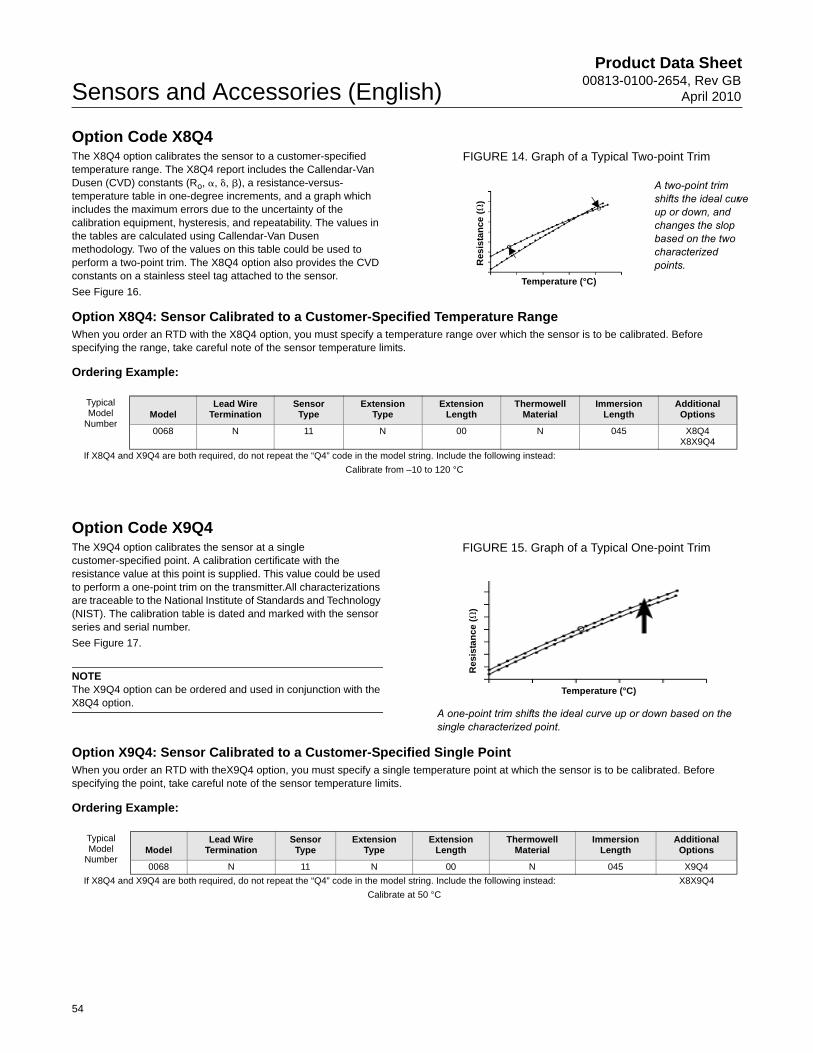
Product Data Sheet00813-0100-2654, Rev GB
April 2010Sensors and Accessories (English)
Option Code X8Q4The X8Q4 option calibrates the sensor to a customer-specified temperature range. The X8Q4 report includes the Callendar-Van Dusen (CVD) constants (Ro, �, �, �), a resistance-versus- temperature table in one-degree increments, and a graph which includes the maximum errors due to the uncertainty of the calibration equipment, hysteresis, and repeatability. The values in the tables are calculated using Callendar-Van Dusen methodology. Two of the values on this table could be used to perform a two-point trim. The X8Q4 option also provides the CVD constants on a stainless steel tag attached to the sensor.
See Figure 16.
FIGURE 14. Graph of a Typical Two-point Trim
Option X8Q4: Sensor Calibrated to a Customer-Specified Temperature RangeWhen you order an RTD with the X8Q4 option, you must specify a temperature range over which the sensor is to be calibrated. Before specifying the range, take careful note of the sensor temperature limits.
Ordering Example:
Option Code X9Q4The X9Q4 option calibrates the sensor at a single customer-specified point. A calibration certificate with the resistance value at this point is supplied. This value could be used to perform a one-point trim on the transmitter.All characterizations are traceable to the National Institute of Standards and Technology (NIST). The calibration table is dated and marked with the sensor series and serial number.
See Figure 17.
NOTEThe X9Q4 option can be ordered and used in conjunction with the X8Q4 option.
FIGURE 15. Graph of a Typical One-point Trim
Option X9Q4: Sensor Calibrated to a Customer-Specified Single PointWhen you order an RTD with theX9Q4 option, you must specify a single temperature point at which the sensor is to be calibrated. Before specifying the point, take careful note of the sensor temperature limits.
Ordering Example:
A two-point trim shifts the ideal curve up or down, and changes the slop based on the two characterized points.
Temperature (°C)
Res
ista
nce
(�
)
Typical Model
NumberModel
Lead Wire Termination
Sensor Type
Extension Type
Extension Length
Thermowell Material
Immersion Length
Additional Options
0068 N 11 N 00 N 045 X8Q4X8X9Q4
If X8Q4 and X9Q4 are both required, do not repeat the “Q4” code in the model string. Include the following instead:
Calibrate from –10 to 120 °C
A one-point trim shifts the ideal curve up or down based on the single characterized point.
Temperature (°C)
Re
sis
tan
ce
(�
)
Typical Model
NumberModel
Lead Wire Termination
Sensor Type
Extension Type
Extension Length
Thermowell Material
Immersion Length
Additional Options
0068 N 11 N 00 N 045 X9Q4
If X8Q4 and X9Q4 are both required, do not repeat the “Q4” code in the model string. Include the following instead: X8X9Q4
Calibrate at 50 °C
54

Product Data Sheet00813-0100-2654, Rev GBApril 2010 Sensors and Accessories (English)
FIGURE 16. Example of Report Provided with X8Q4 Option
55

Product Data Sheet00813-0100-2654, Rev GB
April 2010Sensors and Accessories (English)
56

Product Data Sheet00813-0100-2654, Rev GBApril 2010 Sensors and Accessories (English)
57

Product Data Sheet00813-0100-2654, Rev GB
April 2010Sensors and Accessories (English)
58

Product Data Sheet00813-0100-2654, Rev GBApril 2010 Sensors and Accessories (English)
59
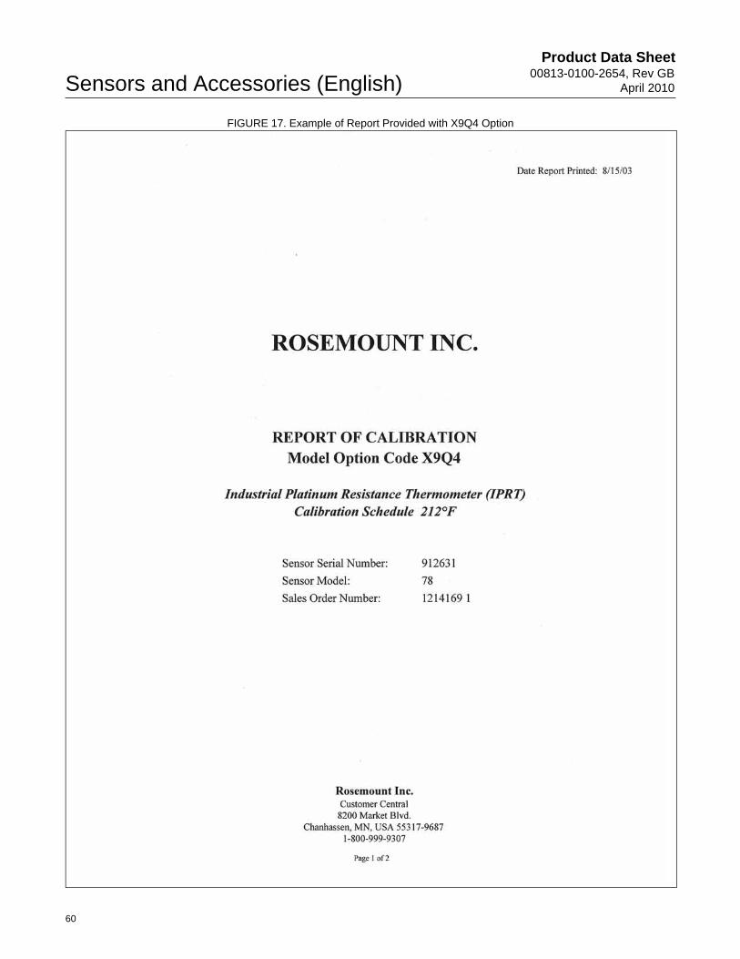
Product Data Sheet00813-0100-2654, Rev GB
April 2010Sensors and Accessories (English)
FIGURE 17. Example of Report Provided with X9Q4 Option
60
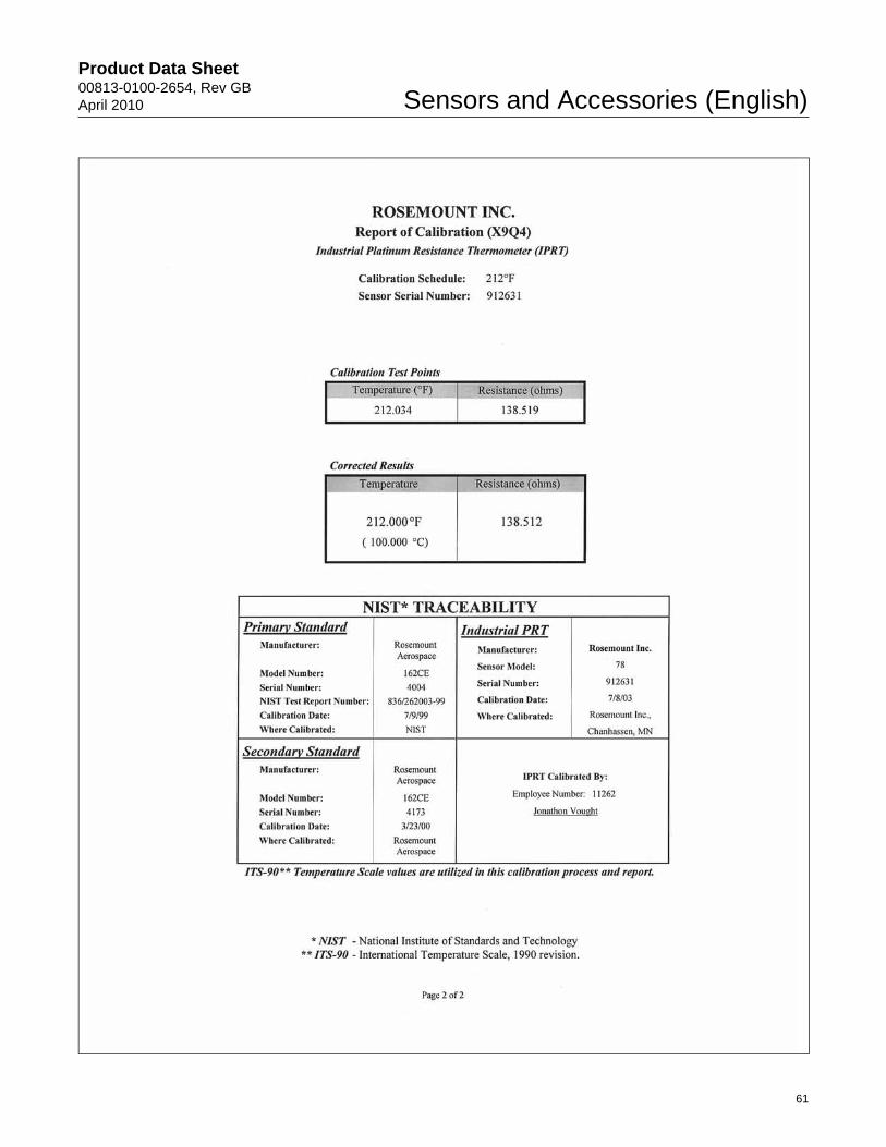
Product Data Sheet00813-0100-2654, Rev GBApril 2010 Sensors and Accessories (English)
61
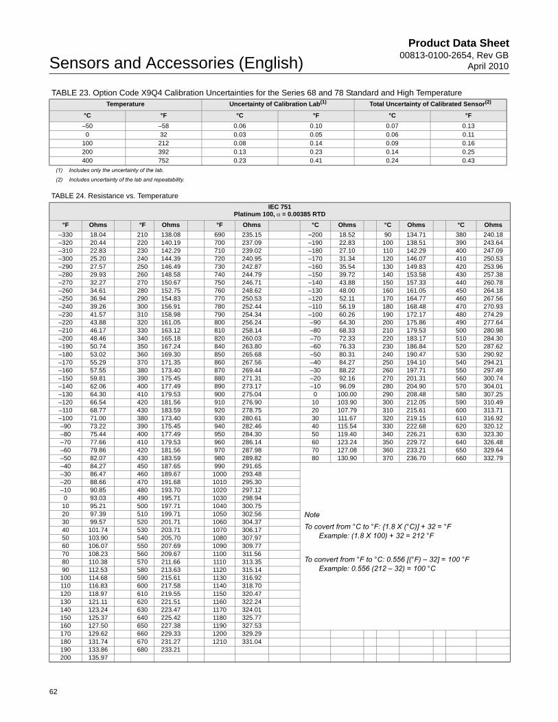
Product Data Sheet00813-0100-2654, Rev GB
April 2010Sensors and Accessories (English)
TABLE 23. Option Code X9Q4 Calibration Uncertainties for the Series 68 and 78 Standard and High Temperature
TABLE 24. Resistance vs. Temperature
Temperature Uncertainty of Calibration Lab(1)
(1) Includes only the uncertainty of the lab.
Total Uncertainty of Calibrated Sensor(2)
(2) Includes uncertainty of the lab and repeatability.
°C °F °C °F °C °F
–50 –58 0.06 0.10 0.07 0.130 32 0.03 0.05 0.06 0.11
100 212 0.08 0.14 0.09 0.16200 392 0.13 0.23 0.14 0.25400 752 0.23 0.41 0.24 0.43
IEC 751Platinum 100, = 0.00385 RTD
°F Ohms °F Ohms °F Ohms °C Ohms °C Ohms °C Ohms
–330 18.04 210 138.08 690 235.15 –200 18.52 90 134.71 380 240.18–320 20.44 220 140.19 700 237.09 –190 22.83 100 138.51 390 243.64–310 22.83 230 142.29 710 239.02 –180 27.10 110 142.29 400 247.09–300 25.20 240 144.39 720 240.95 –170 31.34 120 146.07 410 250.53–290 27.57 250 146.49 730 242.87 –160 35.54 130 149.83 420 253.96–280 29.93 260 148.58 740 244.79 –150 39.72 140 153.58 430 257.38–270 32.27 270 150.67 750 246.71 –140 43.88 150 157.33 440 260.78–260 34.61 280 152.75 760 248.62 –130 48.00 160 161.05 450 264.18–250 36.94 290 154.83 770 250.53 –120 52.11 170 164.77 460 267.56–240 39.26 300 156.91 780 252.44 –110 56.19 180 168.48 470 270.93–230 41.57 310 158.98 790 254.34 –100 60.26 190 172.17 480 274.29–220 43.88 320 161.05 800 256.24 –90 64.30 200 175.86 490 277.64–210 46.17 330 163.12 810 258.14 –80 68.33 210 179.53 500 280.98–200 48.46 340 165.18 820 260.03 –70 72.33 220 183.17 510 284.30–190 50.74 350 167.24 840 263.80 –60 76.33 230 186.84 520 287.62–180 53.02 360 169.30 850 265.68 –50 80.31 240 190.47 530 290.92–170 55.29 370 171.35 860 267.56 –40 84.27 250 194.10 540 294.21–160 57.55 380 173.40 870 269.44 –30 88.22 260 197.71 550 297.49–150 59.81 390 175.45 880 271.31 –20 92.16 270 201.31 560 300.74–140 62.06 400 177.49 890 273.17 –10 96.09 280 204.90 570 304.01–130 64.30 410 179.53 900 275.04 0 100.00 290 208.48 580 307.25–120 66.54 420 181.56 910 276.90 10 103.90 300 212.05 590 310.49–110 68.77 430 183.59 920 278.75 20 107.79 310 215.61 600 313.71–100 71.00 380 173.40 930 280.61 30 111.67 320 219.15 610 316.92–90 73.22 390 175.45 940 282.46 40 115.54 330 222.68 620 320.12–80 75.44 400 177.49 950 284.30 50 119.40 340 226.21 630 323.30–70 77.66 410 179.53 960 286.14 60 123.24 350 229.72 640 326.48–60 79.86 420 181.56 970 287.98 70 127.08 360 233.21 650 329.64–50 82.07 430 183.59 980 289.82 80 130.90 370 236.70 660 332.79–40 84.27 450 187.65 990 291.65
NoteTo covert from °C to °F: {1.8 X (°C)] + 32 = °F
Example: (1.8 X 100) + 32 = 212 °F
To convert from °F to °C: 0.556 [(°F) – 32] = 100 °FExample: 0.556 (212 – 32) = 100 °C
–30 86.47 460 189.67 1000 293.48–20 88.66 470 191.68 1010 295.30–10 90.85 480 193.70 1020 297.12
0 93.03 490 195.71 1030 298.9410 95.21 500 197.71 1040 300.7520 97.39 510 199.71 1050 302.5630 99.57 520 201.71 1060 304.3740 101.74 530 203.71 1070 306.1750 103.90 540 205.70 1080 307.9760 106.07 550 207.69 1090 309.7770 108.23 560 209.67 1100 311.5680 110.38 570 211.66 1110 313.3590 112.53 580 213.63 1120 315.14100 114.68 590 215.61 1130 316.92110 116.83 600 217.58 1140 318.70120 118.97 610 219.55 1150 320.47130 121.11 620 221.51 1160 322.24140 123.24 630 223.47 1170 324.01150 125.37 640 225.42 1180 325.77160 127.50 650 227.38 1190 327.53170 129.62 660 229.33 1200 329.29180 131.74 670 231.27 1210 331.04190 133.86 680 233.21200 135.97
62

Product Data Sheet00813-0100-2654, Rev GBApril 2010 Sensors and Accessories (English)
Mounting Accessories
ROSEMOUNT CONNECTION HEADThe Rosemount Connection head is for general-purpose and spring-loaded sensors. The terminal block has six terminals for either single or dual element sensors. If the sensor assembly is ordered assembled to a Rosemount 248 or 644H head mount transmitter then the terminal block is replaced by the transmitters.
SpecificationsSensor Connection
• 1/2–14 NPT mounting thread. Screw terminals for lead wire connections.
Electrical Connection
• 1/2–14 NPT conduit
Materials of Construction
• Housing: Low copper aluminum
• Paint: Polyurethane
• Cover O-ring: Buna-N
Weight
• 18.5 oz (524 g)
Enclosure Rating
• NEMA 4X, IP66, and IP68
POLYPROPYLENE CONNECTION HEADThe polypropylene connection head (part number 00644-4198-0011) is designed for use with sanitary sensors. It is FDA-compliant, and is resistant to attack by acids, alkalies, and organic solvents.
SpecificationsSensor Connection
• 1/2–14 NPT mounting thread. Screw terminals for lead wire connections
Electrical Connection
• 1/2–14 NPT conduit
Materials of Construction
• Housing: White polypropylene polymer
• O-Ring Seal: Silicone rubber
• Terminals: Nickel-plated brass
Temperature Limits
• –73 to 104 °C (–100 to 220 °F)
Weight
• 0.5 lb
CONNECTION HEADThe Extended Cover Connection Head (P/N 00079-0324-xxxx) provides the additional space required by sensors that have bayonet connectors. This model can also be used with general-purpose and spring-loaded sensors. The terminal block has six terminals for either single- or dual-element sensors.
The Flat Cover Connection Head (P/N 00079-0325-xxxx) is for general-purpose and spring-loaded sensors. The terminal block has six terminals for either single- or dual-element sensors.
SpecificationsSensor Connection
• 1/2–14 ANPT mounting thread. Screw terminals for lead wire connections
Electrical Connection
• 3/4–14 ANPT conduit
Materials of Construction
• Housing: Low-copper aluminum alloy
• O-Ring Seal: Silicone rubber
• Terminals: Nickel-plated brass
Temperature Limits
Enclosure Ratings
• When installed properly, painted connection heads are suitable for indoor and outdoor NEMA 4X and CSA Enclosure Type 4X installations. When installed properly, unpainted connection heads are suitable for NEMA 4 and CSA Enclosure Type 4 installations. See Hazardous Area Approvals for complete installation information
Weight
• 2 lb 8 oz (extended cover)
• 1 lb 9 oz (flat cover)
Head Type Unapproved E5 option E6 option E1 option
Painted –100 to 100 °C–148 to 212 °F
–50 to 85 °C–58 to 185 °F
–50 to 85 °C–58 to 185 °F
–40 to 65 °C–40 to 149 °F
Unpainted –100 to 200 °C–148 to 392 °F
–50 to 85 °C–58 to 185 °F
–50 to 200 °C–58 to 392 °
–40 to 65 °C–40 to 149 °F
63

Product Data Sheet00813-0100-2654, Rev GB
April 2010Sensors and Accessories (English)
Connection Head Model Numbers Connection Head Dimensional Drawing
Model Description
00644-4410-0011 Rosemount Connection Head, painted aluminum
007903252003 Six Terminals with Flat Cover, Unapproved, Unpainted
007903242003 Six Terminals with Extended Cover, Unapproved, Unpainted
007903250002 Six Terminals with Flat Cover, FM Approved, Unpainted
007903240002 Six Terminals with Extended Cover, FM Approved, Unpainted
007903250003 Six Terminals with Flat Cover, CSA Approved, Unpainted
007903240003 Six Terminals with Extended Cover, CSA Approved, Unpainted
007903252005 Six Terminals with Flat Cover, Unapproved, Painted
007903242005 Six Terminals with Extended Cover, Unapproved, Painted
007903250004 Six Terminals with Flat Cover, FM Approved, Painted
007903240004 Six Terminals with Extended Cover, FM Approved, Painted
007903250005 Six Terminals with Flat Cover, CSA Approved, Painted
007903240005 Six Terminals with Extended Cover, CSA Approved, Painted
00644-4198-0011 No Approval Options, White Polypropylene
00065-0305-0001 Round Terminal Block for Rosemount and Polypropylene heads
006444-4431-0001 External ground Screw Assembly for Rosemount Connection Head
00644-4435-0011 Polypropelyne Connection Head with Terminal Block 1/2 in. NPT entries
00079-0329-0001 Kit of 12 Silicone Rubber O-rings for Flat/Extended Heads
Rosemount Connection Head
Polypropylene
Flat Cover Extended Cover Terminal View
Dimensions are in inches (millimeters)
104
100
78
84 (3.331)
118 (4.65)
5.5 (140)
Terminal Block (6 terminals)
1/2–14 ANPT
3/4–14 ANPT
3.5(89)
Chain
4.9 (124)
64
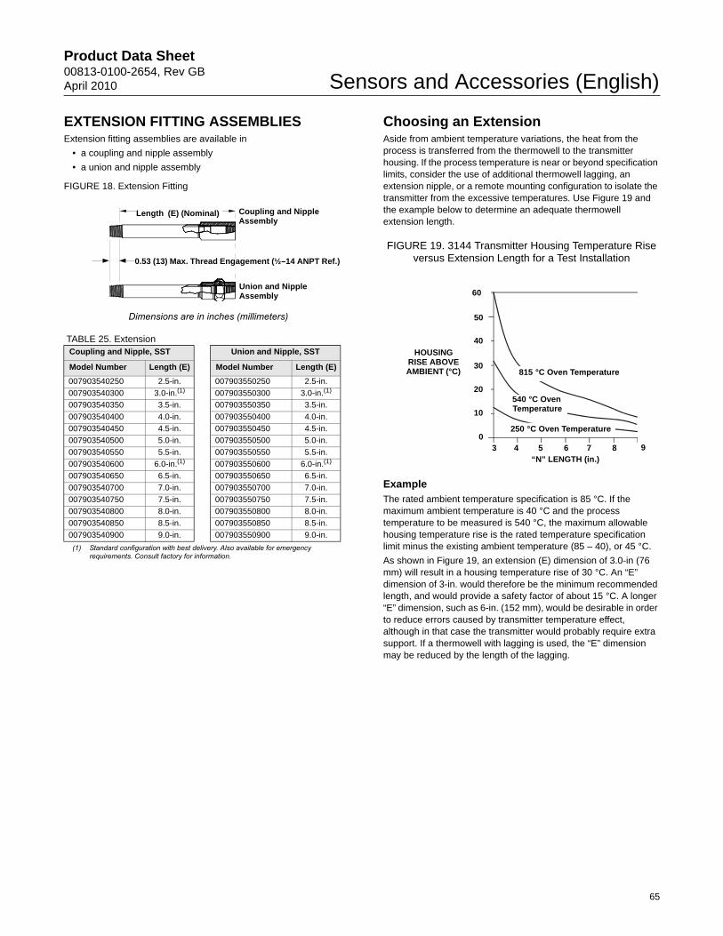
Product Data Sheet00813-0100-2654, Rev GBApril 2010 Sensors and Accessories (English)
EXTENSION FITTING ASSEMBLIESExtension fitting assemblies are available in
• a coupling and nipple assembly
• a union and nipple assembly
TABLE 25. Extension
Choosing an ExtensionAside from ambient temperature variations, the heat from the process is transferred from the thermowell to the transmitter housing. If the process temperature is near or beyond specification limits, consider the use of additional thermowell lagging, an extension nipple, or a remote mounting configuration to isolate the transmitter from the excessive temperatures. Use Figure 19 and the example below to determine an adequate thermowell extension length.
FIGURE 19. 3144 Transmitter Housing Temperature Rise versus Extension Length for a Test Installation
ExampleThe rated ambient temperature specification is 85 °C. If the maximum ambient temperature is 40 °C and the process temperature to be measured is 540 °C, the maximum allowable housing temperature rise is the rated temperature specification limit minus the existing ambient temperature (85 – 40), or 45 °C.
As shown in Figure 19, an extension (E) dimension of 3.0-in (76 mm) will result in a housing temperature rise of 30 °C. An “E” dimension of 3-in. would therefore be the minimum recommended length, and would provide a safety factor of about 15 °C. A longer “E” dimension, such as 6-in. (152 mm), would be desirable in order to reduce errors caused by transmitter temperature effect, although in that case the transmitter would probably require extra support. If a thermowell with lagging is used, the “E” dimension may be reduced by the length of the lagging.
FIGURE 18. Extension Fitting
Dimensions are in inches (millimeters)
Coupling and Nipple, SST Union and Nipple, SST
Model Number Length (E) Model Number Length (E)
007903540250 2.5-in. 007903550250 2.5-in.
007903540300 3.0-in.(1) 007903550300 3.0-in.(1)
(1) Standard configuration with best delivery. Also available for emergency requirements. Consult factory for information.
007903540350 3.5-in. 007903550350 3.5-in.
007903540400 4.0-in. 007903550400 4.0-in.
007903540450 4.5-in. 007903550450 4.5-in.
007903540500 5.0-in. 007903550500 5.0-in.
007903540550 5.5-in. 007903550550 5.5-in.
007903540600 6.0-in.(1) 007903550600 6.0-in.(1)
007903540650 6.5-in. 007903550650 6.5-in.
007903540700 7.0-in. 007903550700 7.0-in.
007903540750 7.5-in. 007903550750 7.5-in.
007903540800 8.0-in. 007903550800 8.0-in.
007903540850 8.5-in. 007903550850 8.5-in.
007903540900 9.0-in. 007903550900 9.0-in.
0.53 (13) Max. Thread Engagement (½–14 ANPT Ref.)
Coupling and Nipple Assembly
Union and Nipple Assembly
Length (E) (Nominal)
HOUSING RISE ABOVE AMBIENT (°C)
“N” LENGTH (in.)3 4 5 6 7 8 9
0
60
50
20
10
30
40
815 °C Oven Temperature
540 °C Oven Temperature
250 °C Oven Temperature
65
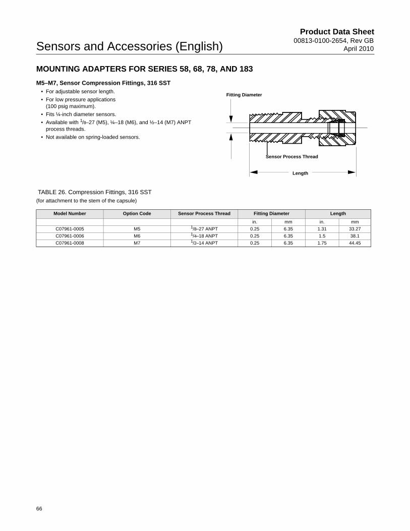
Product Data Sheet00813-0100-2654, Rev GB
April 2010Sensors and Accessories (English)
MOUNTING ADAPTERS FOR SERIES 58, 68, 78, AND 183
M5–M7, Sensor Compression Fittings, 316 SST • For adjustable sensor length.
• For low pressure applications(100 psig maximum).
• Fits ¼-inch diameter sensors.
• Available with 1/8–27 (M5), ¼–18 (M6), and ½–14 (M7) ANPT process threads.
• Not available on spring-loaded sensors.
TABLE 26. Compression Fittings, 316 SST (for attachment to the stem of the capsule)
Sensor Process Thread
Fitting Diameter
Length
Model Number Option Code Sensor Process Thread Fitting Diameter Length
in. mm in. mm
C07961-0005 M5 1/8–27 ANPT 0.25 6.35 1.31 33.27
C07961-0006 M6 1/4–18 ANPT 0.25 6.35 1.5 38.1
C07961-0008 M7 1/2–14 ANPT 0.25 6.35 1.75 44.45
66

Product Data Sheet00813-0100-2654, Rev GBApril 2010 Sensors and Accessories (English)
LEAD WIRE EXTENSIONS, CONNECTORS, AND SEALSThe following options are available on most Series 68 and 78 sensors. They are not available for use on Series 58C, 68Q, and 183 sensors or with SAA or ATEX/ISSeP Flameproof approval (Option Codes E7 or E1).
A1–A8, Twisted Lead Wire Extension• Lead wire connections are silver brazed and
individually insulated by shrinkable PTFE tubes
• Withstands 95 percent relative humidity
• 200° C (392° F) maximum temperature
• Available with single or dual-element sensors
Twisted Lead WIre Extension(Option Codes A1 – A8)
Shielded Cable Lead Wire Extension(Option Codes B1 – B8)
Armored Cable Lead Wire Extension(Option Codes C1 – C8)
Armored CableMating Plug with Lead
Wire Extension(Option Codes L1 – L8) Armored Cable Lead Wire Extension with
Electrical Plug(Option Codes D1 – D8)
4-Pin Connector(Option Codes H1 – H8) Bayonet Connector
(Option Code F1)
3244MV Transmitter
Moisture-Proof Seal Assembly for Armored Cable (Option Code J1)
Armored Cable Lead Wire Extension (Option Codes C1 – C8)
(Capsule Sensor Only)
(Capsule Sensor with Standard Adapter)
Option Code Y Length (ft) Option Code Y Length (ft)
A1 11/2 A5 24A2 3 A6 50A3 6 A7 75A4 12 A8 100
Not available for use with Series 68Q Sanitary RTDs and 183 thermocouples or with SAA or ATEX/ISSeP flameproof approval (option codes E7 or E1)
Dimensions are in inches (millimeters)
22-Gauge PTFE Lead Wire
6 (152) [Ref.]
Sensor PTFE
Y
67

Product Data Sheet00813-0100-2654, Rev GB
April 2010Sensors and Accessories (English)
B1–B8, Shielded Cable Lead Wire Extension• Copper shielded cable prevents electrical noise distortions to
sensor signal output
• Withstands 95 percent relative humidity
• 200° C (392° F) maximum temperature
C1–C8, Armored Cable Lead Wire Extension• Provides lead wire protection
in heavy duty environments.
• Withstands 95 percent relative humidity
• 200° C (392° F) maximum temperature
• Available with single or dual-element sensors
D1–D8, ARMORED CABLE LEAD WIRE EXTENSION WITH ELECTRICAL PLUG
• Provides lead wire protection in heavy-duty environments
• Provides quick-disconnect capability
• Withstands 95 percent relative humidity
Option Code Y Length (ft) Option Code Y Length (ft)
B1 11/2 B5 24B2 3 B6 50B3 6 B7 75B4 12 B8 100
Not available for 58C, 68Q, and 183 sensors or with SAA or ATEX/ISSeP flameproof approval (option codes E7 or E1)Dimensions are in inches (millimeters)
2.75 (70) [max.]
0.375 (10) DiameterSensor0.25 (6) [Approx.]
Rubber SealShielded Cable PTFE Jacket22-Gauge PTFE-Insulated Wires
Y
Option Code Y Length (ft) Option Code Y Length (ft)
C1 11/2 C5 24C2 3 C6 50C3 6 C7 75C4 12 C8 100
Not available for 58C, 68Q, and 183 sensors or with SAA or ATEX/ISSeP flameproof approval (option codes E7 or E1)Dimensions are in inches (millimeters)
6.0(152)
22-Gauge PTFE-Insulated Wire
2.75 (70) [Max.]
0.375 (10) Diameter 0.445 (11)Sensor
Armor Cable 0.34 (8.64) O.D.
Y
Option Code Y Length (ft) Option Code Y Length (ft)
D1 11/2 D5 24D2 3 D6 50D3 6 D7 75D4 12 D8 100
Not available for 58C, 68Q, and 183 sensors or with SAA or ATEX/ISSeP flameproof approval (option codes E7 or E1)Dimensions are in inches (millimeters)
Mates with Option Codes L1–L8
Armor Cable 0.34 (8.64) OD)
2.75 (70) [Max.]
0.375 (10) DiameterSensor
Y
68

Product Data Sheet00813-0100-2654, Rev GBApril 2010 Sensors and Accessories (English)
L1–L8, ARMORED CABLE MATING PLUG WITH LEAD WIRE EXTENSION
• Completes quick-disconnect capability for armored cable
• Withstands 95 percent relative humidity
• Twisted lead wire extension for lowest cost installation
F1, 4-PIN BAYONET CONNECTOR• Provides quick-disconnect capability
• Withstands 100 percent relative humidity with connector mate
• Available for capsule and general purpose with 4-wire lead wire configuration only
H1–H8, 4-PIN CONNECTOR MATING PLUG WITH LEAD WIRE EXTENSION
• Completes the quick-disconnect capability of connector
• Provides twisted lead wire extension for remote installations
• Withstands 100 percent relative humidity with connector mate
• F1 connector is required if H1–H8 lead wire extension is used
Option Code Y Length (ft) Option Code Y Length (ft)
L1 11/2 L5 24L2 3 L6 50L3 6 L7 75L4 12 L8 100
Not available for 58C, 68Q, and 183 sensors or with SAA or ATEX/ISSeP flameproof approval (option codes E7 or E1)Dimensions are in inches (millimeters)
Mates with Option Codes D1–D822-Gauge PTFE Lead Wire
Y
Not available for 58C, 68Q, and 183 sensors, or with FM or CSA explosion-proof, or with SAA or ATEX/ISSeP flameproof approval (option codes E5, E6, E7, or E1)
Dimensions are in inches (millimeters)
Receptance Shell and PinFinish Are Nickel Plate
2.0 (51)
Mates with Option Codes H1–H80.652 (17)Dia. Max.
3.0 (76)
150 °C Max. for Series 68 and 78
Wiring SchematicA
4-Wire
Sensor
0.375 (10) Diameter
BCD
Option Code Y Length (ft) Option Code Y Length (ft)
H1 11/2 H5 24H2 3 H6 50H3 6 H7 75H4 12 H8 100
Not available for 58C, 68Q, and 183 sensors, or with FM or CSA explosion-proof, or with SAA or ATEX/ISSeP flameproof approval (option codes E5, E6, E7, or E1)
Dimensions are in inches (millimeters)
22-Gauge PTFE Lead Wire
4-Pin Connector (Mates with Option Code F1)
Y
69

Product Data Sheet00813-0100-2654, Rev GB
April 2010Sensors and Accessories (English)
J1, MOISTURE-PROOF SEAL ASSEMBLY FOR ARMORED CABLE
• Prevents moisture migration through armored cable
• For use in humid environments but not for direct liquid immersion
• Non-disconnectable type assembly with armored cable and sensor
THERMOWELLSTo simplify ordering, the previous Series 79, 80, and 81 thermowell offerings are all included in the new Series 91 thermowell option.
MaterialsRosemount Thermowells are supplied in most materials required for industrial applications. Standard materials are 316 SST, 304 SST, and C1018 carbon steel. For corrosive environments, special materials such as Monel®, Hastelloy®, and Inconel 600 are available. Consult factory for other material availability.
Strength (Pressure and Flow Vibration) The strength of a thermowell depends on several parameters that relate thermowell construction to the installation environment. For most industrial applications, standard Rosemount thermowells provide the necessary strength if the material, style, and length are correct for the application. The proper selection of a thermowell depends on fluid type, temperature, pressure, and fluid velocity. It is important to note that most thermowell failures are caused by vibration that is induced by fluid flow. If static pressure strength is a major consideration, refer to Table 27 for standard material ratings for a 1/2-inch tip. Tapered thermowells are offered for additional strength.
Strength CalculationRosemount Inc. has the ability to perform thermowell frequency calculations to verify that the thermowell dimensions you provide are appropriate for your specific application. To take advantage of this calculation, fill out and return the Configuration Data Sheet.
ConstructionAll thermowell bodies with an overall length less than 42-in. are machined from solid bar stock to ensure water-tightness. Flange mounts are welded to the thermowell body. Standard construction provides immersion lengths (U) from 2½ to 48 inches with overall lengths (L) from 4 to 59 inches respectively. Thermowells with overall lengths larger than 42-in. will be a 3-piece welded construction. Consult the factory for more information on welded 3-piece construction thermowells.
Identification DataThe part number is etched on each thermowell. Additional tagging for specific customer requirements is available.
InstallationFor dimensional drawings of Thread Mounted, Weld Mounted, and Flange Mounted Thermowells, refer to Figure 20, 22, and 24.
Not available for 58C, 68Q, and 183 sensors, or with FM or CSA explosion-proof, or with SAA or ATEX/ISSeP flameproof approval (option codes E5, E6, E7, or E1).Moisture-proof seal assembly must be ordered with armored cable lead wire extension (option codes C1 – C8)
Dimensions are in inches (millimeters)
Armored Cable Lead Wire (Specify Option Codes C1–C8)
Sensor
Nipple, 304 SST, 1/2–14 ANPT 1.12 (28.45) Long
Moisture-Proof Seal (J1)Compression Fitting
J1
TABLE 27. Thermowell Material Rating
Process Rating(1) (psi) at Temperature (°F)
Material Recommended Usage 0 °F 300 °F 500 °F 700 °F 900 °F 1100 °F 1300 °F
304 SST Good resistance to oxidation 5600 4800 4700 4600 3400 2400 780316 SST Good resistance to corrosion. Better resistance to
chemical attack than 304 SST5600 5400 5300 5200 4400 3200 1250
Carbon Steel For non-corrosive service 3700 3700 3700 3650 2000 — —
(1) In case of an explosion, the integrity of the thermowell is maintained to the specified pressures.
70

Product Data Sheet00813-0100-2654, Rev GBApril 2010 Sensors and Accessories (English)
ORDERING INFORMATION
TABLE 28. Series 91 Thermowells★ The Standard offering represents the most common options. The starred options (★) should be selected for best delivery.__The Expanded offering is subject to additional delivery lead time.
Model Description
0091 Thermowells
Thermowell Material
Standard Standard
A Type 316 SST ★
B Type 304 SST ★
C Carbon Steel ★
D 316L SST ★
E 304L SST ★
Expanded
F Alloy 20
G Alloy 400
H Alloy 600
J Alloy C-276
L Alloy B
M 304 SST with Teflon (PTFE) coating
P Chrome Molybdenum F22
R Nickel 200
T Titanium
U(2) 316 SST with tantalum sheath
V 310 SST
W 321 SST
X Special Material
Y 316Ti SST
Z Chrome Molybdenum F11
Sensor/Immersion Length (U) in inches(1)
Standard Standard
015(2) 1.5 in. ★
020 2.0 in. ★
025 2.5 in. ★
030 3.0 in. ★
035 3.5 in. ★
040 4.0 in. ★
045 4.5 in. ★
050 5.0 in. ★
055 5.5 in. ★
060 6.0 in. ★
065 6.5 in. ★
070 7.0 in. ★
075 7.5 in. ★
080 8.0 in. ★
085 8.5 in. ★
090 9.0 in. ★
095 9.5 in. ★
100 10.0 in. ★
105 10.5 in. ★
110 11.0 in. ★
115 11.5 in. ★
120 12.0 in. ★
125 12.5 in. ★
130 13.0 in. ★
135 13.5 in. ★
71

Product Data Sheet00813-0100-2654, Rev GB
April 2010Sensors and Accessories (English)
140 14.0 in. ★
145 14.5 in. ★
150 15.0 in. ★
155 15.5 in. ★
160 16.0 in. ★
165 16.5 in. ★
170 17.0 in. ★
175 17.5 in. ★
180 18.0 in. ★
185 18.5 in. ★
190 19.0 in. ★
195 19.5 in. ★
200 20.0 in. ★
205 20.5 in. ★
210 21.0 in. ★
215 21.5 in. ★
220 22.0 in. ★
225 22.5 in. ★
230 23.0 in. ★
240 24.0 in. ★
250 25.0 in. ★
260 26.0 in. ★
270 27.0 in. ★
280 28.0 in. ★
290 29.0 in. ★
300 30.0 in. ★
310 31.0 in. ★
320 32.0 in. ★
330 33.0 in. ★
340 34.0 in. ★
350 35.0 in. ★
360 36.0 in. ★
370 37.0 in. ★
380 38.0 in. ★
390 39.0 in. ★
400 40.0 in. ★
410 41.0 in. ★
420 42.0 in. ★
430 43.0 in. ★
440 44.0 in. ★
450 45.0 in. ★
460 46.0 in. ★
470 47.0 in. ★
480 48.0 in. ★
Thermowell Mounting Style Stem Style Tip A (in.) Root B (in.)
Standard Standard
T20 Thread, 1/2–14 ANPT Stepped 0.50 0.63 ★
T22 Thread, 3/4–14 ANPT Stepped 0.50 0.75 ★
T24 Thread, 1–11.5 ANPT Stepped 0.50 0.88 ★
T26 Thread, 3/4–14 ANPT Tapered 0.63 0.88 ★
T28 Thread, 1–11.5 ANPT Tapered 0.63 1.06 ★
T30 Thread, 11/2–11.5 ANPT Tapered 0.75 1.50 ★
T32 Thread, 1/2–14 ANPT Straight 0.50 0.50 ★
TABLE 28. Series 91 Thermowells★ The Standard offering represents the most common options. The starred options (★) should be selected for best delivery.__The Expanded offering is subject to additional delivery lead time.
72

Product Data Sheet00813-0100-2654, Rev GBApril 2010 Sensors and Accessories (English)
T34 Thread, 3/4–14 ANPT Straight 0.75 0.75 ★
T36 Thread, 1–11.5 ANPT Straight 0.75 0.75 ★
T38 Thread, 3/4–14 ANPT Straight 0.50 0.50 ★
T44 Thread, 1/2–14 ANPT Tapered 0.50 0.63 ★
W38 Weld, 3/4-in. pipe Stepped 0.50 0.75 ★
W40 Weld, 1-in. pipe Stepped 0.50 0.88 ★
W42 Weld, 3/4-in. pipe Tapered 0.63 0.88 ★
W44 Weld, 1-inch Pipe, Tapered 0.75 1.00 ★
W46 Weld, 11/4-inch Pipe Tapered 0.75 1.25 ★
W48 Weld, 3/4-inch Pipe Straight 0.75 0.75 ★
W50 Weld, 1-inch Pipe Straight 0.75 0.75 ★
F10 Flange, F = 2-inch, Class 150 Straight 0.75 0.75 ★
F12 Flange, F = 3-inch, Class 150 Straight 0.75 0.75 ★
F52 Flange, F = 1-inch, Class 150 Stepped 0.50 0.75 ★
F54 Flange, F = 1½-inch, Class 150 Stepped 0.50 0.75 ★
F56 Flange, F = 2-inch, Class 150 Stepped 0.50 0.75 ★
F58 Flange, F = 1-inch, Class 150 Tapered 0.75 1.00 ★
F60 Flange, F = 1½-inch, Class 150 Tapered 0.75 1.00 ★
F62 Flange, F = 2-inch, Class 150 Tapered 0.75 1.25 ★
F64 Flange, F = 1-inch, Class 150 Straight 0.75 0.75 ★
F66 Flange, F = 1½-inch, Class 150 Straight 0.75 0.75 ★
F70 Flange, F = 1-inch, Class 300 Stepped 0.50 0.75 ★
F72 Flange, F = 1½-inch, Class 300 Stepped 0.50 0.75 ★
F74 Flange, F = 2-inch, Class 300 Stepped 0.50 0.75 ★
F76 Flange, F = 1-inch, Class 300 Tapered 0.75 1.00 ★
F78 Flange, F = 1½-inch, Class 300 Tapered 0.75 1.00 ★
F80 Flange, F = 2-inch, Class 300 Tapered 0.75 1.25 ★
F82 Flange, F = 1-inch, Class 300 Straight 0.75 0.75 ★
F84 Flange, F = 1½-inch, Class 300 Straight 0.75 0.75 ★
F86 Flange, F = 2-inch, Class 300 Straight 0.75 0.75 ★
F88(3) Flange, F = 1-inch, Class 600 Stepped 0.50 0.75 ★
F90(3) Flange, F = 1½-inch, Class 600 Stepped 0.50 0.75 ★
F92(3) Flange, F = 2-inch, Class 600 Stepped 0.50 0.75 ★
F94(3) Flange, F = 1-inch, Class 600 Tapered 0.75 1.00 ★
F96(3) Flange, F = 1½-inch, Class 600 Tapered 0.75 1.00 ★
F98(3) Flange, F = 2-inch, Class 600 Tapered 0.75 1.25 ★
F02(3) Flange, F = 1-inch, Class 600 Straight 0.75 0.75 ★
F04(3) Flange, F = 1½-inch, Class 600 Straight 0.75 0.75 ★
F06(3) Flange, F = 2-inch, Class 600 Straight 0.75 0.75 ★
F16(3) Flange, F = 1½-inch, Class 900 Tapered 0.75 1.00 ★
F34(3) Flange, F = 1½-inch, Class 1500 Tapered 0.75 1.00 ★
F24(3) Flange, F = 2-inch, Class 1500 Tapered 0.75 1.25 ★
F08(4) Flange, F = 1½-inch, Class 2500 Tapered 0.75 1.00 ★
Q02(5) Sanitary, 1-in.,Tri-Clamp Stepped 0.50 0.75 ★
Q04(6) Sanitary, 11/2-in., Tri-Clamp Stepped 0.50 0.75 ★
Q06(6) Sanitary, 2-in., Tri-Clamp Stepped 0.50 0.75 ★
Q08(6) Sanitary, 3-in.,Tri-Clamp Stepped 0.50 0.75 ★
Q20(6) Sanitary, 3/4-in., Tri-Clamp Straight 0.44 0.44 ★
Q22(6) Sanitary, 1-in.,Tri-Clamp Straight 0.50 0.50 ★
Q24(6) Sanitary, 11/2-in., Tri-Clamp Straight 0.50 0.50 ★
Q26(6) Sanitary, 2-in., Tri-Clamp Straight 0.50 0.50 ★
Q28(6) Sanitary, 3-in.,Tri-Clamp Straight 0.50 0.50 ★
TABLE 28. Series 91 Thermowells★ The Standard offering represents the most common options. The starred options (★) should be selected for best delivery.__The Expanded offering is subject to additional delivery lead time.
73
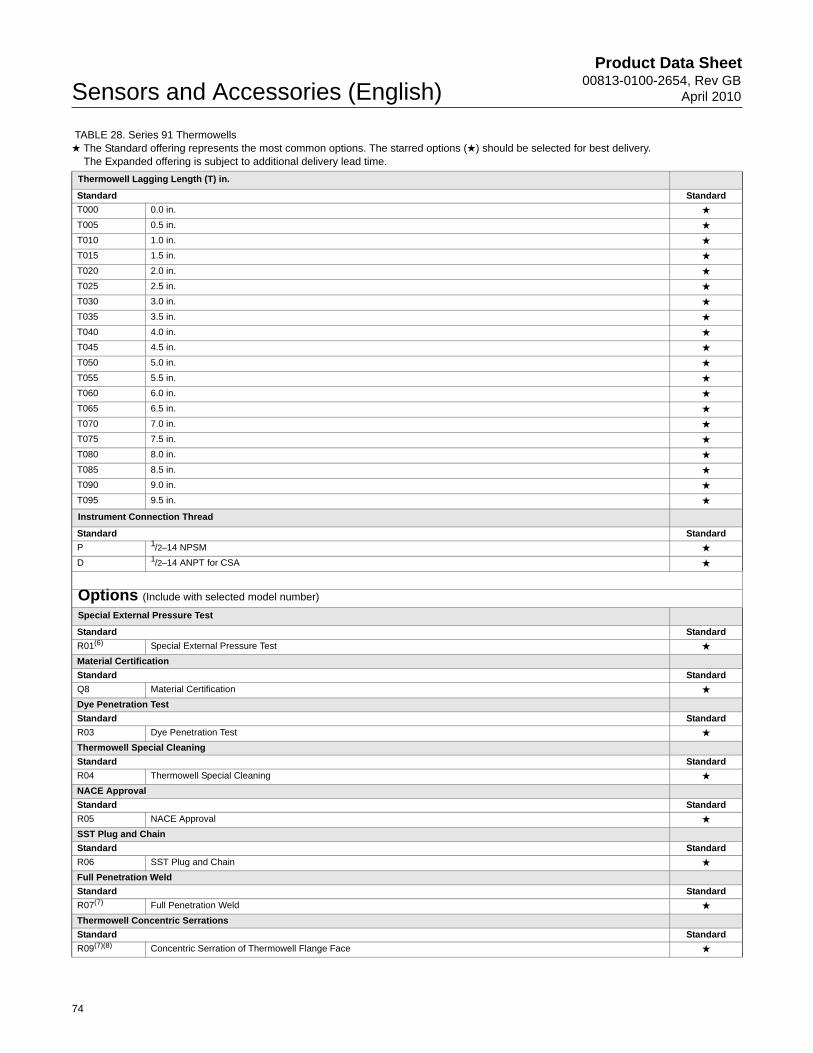
Product Data Sheet00813-0100-2654, Rev GB
April 2010Sensors and Accessories (English)
Thermowell Lagging Length (T) in.
Standard Standard
T000 0.0 in. ★
T005 0.5 in. ★
T010 1.0 in. ★
T015 1.5 in. ★
T020 2.0 in. ★
T025 2.5 in. ★
T030 3.0 in. ★
T035 3.5 in. ★
T040 4.0 in. ★
T045 4.5 in. ★
T050 5.0 in. ★
T055 5.5 in. ★
T060 6.0 in. ★
T065 6.5 in. ★
T070 7.0 in. ★
T075 7.5 in. ★
T080 8.0 in. ★
T085 8.5 in. ★
T090 9.0 in. ★
T095 9.5 in. ★
Instrument Connection Thread
Standard Standard
P 1/2–14 NPSM ★
D 1/2–14 ANPT for CSA ★
Options (Include with selected model number)
Special External Pressure Test
Standard Standard
R01(6) Special External Pressure Test ★
Material Certification
Standard Standard
Q8 Material Certification ★
Dye Penetration Test
Standard Standard
R03 Dye Penetration Test ★
Thermowell Special Cleaning
Standard Standard
R04 Thermowell Special Cleaning ★
NACE Approval
Standard Standard
R05 NACE Approval ★
SST Plug and Chain
Standard Standard
R06 SST Plug and Chain ★
Full Penetration Weld
Standard Standard
R07(7) Full Penetration Weld ★
Thermowell Concentric Serrations
Standard Standard
R09(7)(8) Concentric Serration of Thermowell Flange Face ★
TABLE 28. Series 91 Thermowells★ The Standard offering represents the most common options. The starred options (★) should be selected for best delivery.__The Expanded offering is subject to additional delivery lead time.
74

Product Data Sheet00813-0100-2654, Rev GBApril 2010 Sensors and Accessories (English)
75
Ordering Example
Flat Faced Flange
Standard Standard
R10 (7)(8) Flat Face Flange ★
Vent Hole
Standard Standard
R11 Vent Hole ★
Special Surface Finish
Standard Standard
R14(9) Thermowell Special Surface Finish (12 Ra Max) (Maximum (U) length = 22.5 in.) ★
Ring Joint Flange
Standard Standard
R16(3)(7)(8) Ring Joint Flange (Not available with 0-in. (T) length) ★
Electropolish
Standard Standard
R20(10) Electropolish ★
Wake Frequency
Standard Standard
R21 Wake Frequency-Thermowell Strength Calculation ★
Internal Pressure Test
Standard Standard
R22 Internal Pressure Test ★
Brass Plug & Chain
Standard Standard
R23 Brass Plug & Chain ★
Canadian Registration No.
Expanded
R24 CRN Marking for British Columbia
R25 CRN Marking for Alberta
R26 CRN Marking for Saskatchewan
R27 CRN Marking for Manitoba
R28 CRN Marking for Ontario
R29 CRN Marking for Quebec
R30 CRN Marking for New Brunswick
R31 CRN Marking for Nova Scotia
R32 CRN Marking for Prince Edward Island
R33 CRN Marking for Yukon Territory
R34 CRN Marking for Northwest Territory
R35 CRN Marking for Nunavut
R36 CRN Marking for Newfoundland and Labrador
Twell From Hex Stock
Expanded
R37 Thermowell From Hex stock
(1) Thermowells with an overall lengths (“U” + “T” + 1.75-in.) of 36-in. or less are machined from solid bar stock. Thermowells with an overall length larger than 42-in. will be constructed using a welded 3-piece design and are available only with a stepped stem style.
(2) Available in straight stem only
(3) Not available with 0-in. (T) length.
(4) Not available with 0- or 1/2-in. (T) length.
(5) Limited to 24” immersion length and 316 or 304 SST materials only.
(6) Maximum (U) length = 42.0-in.
(7) Available on flanged thermowells only.
(8) Only one flange face option allowed.
(9) Maximum (U) length = 22.5 inches.
(10) Not available on flanged thermowells and L lengths longer than 24”.
TABLE 28. Series 91 Thermowells★ The Standard offering represents the most common options. The starred options (★) should be selected for best delivery.__The Expanded offering is subject to additional delivery lead time.
Typical Model Number Model Material
Immersion Length Mounting Style
LaggingLength Connection Thread Additional Options
0091 A 030 F52 T040 P R01R05R07

Product Data Sheet00813-0100-2654, Rev GB
April 2010Sensors and Accessories (English)
FIGURE 20. Thread Mounted Thermowells
Straight
Thread (P) Hex Size Inches (H)
0.5 – 0.75 ANPT 1.125
1–11.5 ANPT 1.375
Tapered
Thread (P) Hex Size Inches (H)
0.5 – 0.75 ANPT 1.125
1–11.5 ANPT 1.375
* 1/2–14 ANPT threads are availableDimensions are in inches (millimeters)
Lagging Extension, Nom.
½–14 NPSM*
0.875 (22) Max.
0.25 (6)Nominal
Inside Diameter 0.26 (7)
L
A Tip Diameter
H
T U
P Process Mounting Thread
R37 Option Hex Stock
Wrench and ThreadAllowance1.75 (44)
Lagging Extension, Nom.
½–14 NPSM*
0.25 (6)Nominal
Inside Diameter0.26 (7)
0.875 (22) Max.
U
A Tip Diameter
P Process Mounting Thread
L
T
H
Root Diameter B
Wrench and ThreadAllowance1.75 (44)
76

Product Data Sheet00813-0100-2654, Rev GBApril 2010 Sensors and Accessories (English)
FIGURE 21. Thread Mounted Thermowells (continued)
Stepped
Stepped, For Thermowells with Overall Length Greater than 42-in. (3-Piece Construction)
Thread (P) Hex Size Inches (H)
0.5 – 0.75 ANPT 1.125
1–11.5 ANPT 1.375
* 1/2–14 ANPT threads are availableDimensions are in inches (millimeters)
Lagging Extension, Nom.
½–14 NPSM*
0.25 (6)Nominal
Inside Diameter0.26 (7)
2.5 (64)
P Process Mounting Thread0.875
(22) Max.L
H
T U
B
A Tip Diameter
Root Diameter
R37 Option Hex Stock
Wrench and ThreadAllowance1.75 (44)
2.5 (64)U
Welds
L
T
0.25 (6)
Pipe
H
0.26 (7) Nominal
½–14 NPSM*B
A TipDiameter
R37 Option Hex Stock
Wrench and ThreadAllowance1.75 (44)
77

Product Data Sheet00813-0100-2654, Rev GB
April 2010Sensors and Accessories (English)
FIGURE 22. Weld Mounted Thermowells
Straight
Pipe Size Socket Size (S) Diameter
0.75-in. 1.050 ±0.010
1-in. 1.315 ±0.010
Tapered
Pipe Size Socket Size (S) Diameter
0.75-in. 1.050 ±0.010
1-in. 1.315 ±0.010
* 1/2–14 ANPT threads are availableDimensions are in inches (millimeters)
½–14 NPSM*
0.25 (6) Nominal
Inside Diameter 0.26 (7)
1.75(44)
0.875 (22) Max.
L
T U
A Tip Diameter
S Socket Weld Diameter
Root Diameter B½–14 NPSM*
0.25 (6) Nominal
Inside Diameter 0.26 (7)
1.75(44)
0.875 (22)
A Tip Diameter
S Socket Weld Diameter
T U
L
78

Product Data Sheet00813-0100-2654, Rev GBApril 2010 Sensors and Accessories (English)
FIGURE 23. Weld Mounted Thermowells (continued)
Stepped
Stepped, For Thermowells with Overall Length Greater than 42-in. (3-Piece Construction)
Pipe Size Socket Size (S) Diameter
0.75-in. 1.050 ±0.010
1-in. 1.315 ±0.010
* 1/2–14 ANPT threads are availableDimensions are in inches (millimeters)
½–14 NPSM*
0.25 (6)Nominal
Inside Diameter 0.26 (7)
1.75(44)
2.5 (64)
L
A Tip Diameter
U
B Root Diameter
T
0.875 (22) Max.S Socket Weld Diameter
U
T 1.75 (44)
Pipe
0.25 (6)
2.5 (64)
L
Welds
0.26 (7) Nominal
S Socket Weld Diameter
½–14
79

Product Data Sheet00813-0100-2654, Rev GB
April 2010Sensors and Accessories (English)
FIGURE 24. Flange Mounted Thermowells
Straight
Tapered
Class 150 Class 600
Size (in.) O.D. (E) Circle (F) # of holes and dia. (G)
thickness (in.) (H)
Size (in.) O.D. (E) Circle (F) # of holes and dia. (G)
thickness (in.) (H)
1.0 4.25 3.12 four-0.625 0.5625 1.0 4.88 3.5 four-0.75 0.94
1.5 5.0 3.88 four-0.625 0.6875 1.5 6.12 4.5 four-0.88 1.13
2.0 6.0 4.75 four-0.75 0.75 2.0 6.5 5.0 eight-0.75 1.25
3.0 7.5 6.00 four-0.75 0.94 Class 900 and 1500
Class 300 1.5 7.0 4.88 four-1.12 1.5
1.0 4.88 3.5 four-0.75 0.69 Class 2500
1.5 6.12 4.5 four-0.88 0.81 1.5 8.0 5.75 four-1.25 2.0
2.0 6.5 5.0 eight-0.75 0.88
* 1/2–14 ANPT threads are availableDimensions are in inches (millimeters)
Flange Mount
0.25 (6) Nominal
1.25 (32) Diameter
1.75
½–14 NPSM*
0.875 (22) Max.
Inside Diameter 0.26 (7)
U
H
LF
E
GT
A Tip Diameter
Flange Mount
Inside Diameter 0.26 (7)
0.25 (6) Nominal
1.25 (32) Diameter
R Root Diameter
1.75(44)
0.875 (22) Max.
A Tip Diameter
UT
½–14NPSM*
F
E
G
H
L
80

Product Data Sheet00813-0100-2654, Rev GBApril 2010 Sensors and Accessories (English)
FIGURE 25. Flange Mounted Thermowells (continued)
Stepped
Stepped, For Thermowells with Overall Length Greater than 42-in. (3-Piece Construction)
Class 150 Class 600
Size (in.) O.D. (E) Circle (F) # of holes and dia. (G)
thickness (in.) (H)
Size (in.) O.D. (E) Circle (F) # of holes and dia. (G)
thickness (in.) (H)
1.0 4.25 3.12 four-0.625 0.5625 1.0 4.88 3.5 four-0.75 0.94
1.5 5.0 3.88 four-0.625 0.6875 1.5 6.12 4.5 four-0.88 1.13
2.0 6.0 4.75 four-0.75 0.75 2.0 6.5 5.0 eight-0.75 1.25
3.0 7.5 6.00 four-0.75 0.94 Class 900 and 1500
Class 300 1.5 7.0 4.88 four-1.12 1.5
1.0 4.88 3.5 four-0.75 0.69 Class 2500
1.5 6.12 4.5 four-0.88 0.81 1.5 8.0 5.75 four-1.25 2.0
2.0 6.5 5.0 eight-0.75 0.88
* 1/2–14 ANPT threads are availableDimensions are in inches (millimeters)
1.75(44)
Flange Mount
0.25 (6) Nominal
1.25 (32) Diameter ½–14NPSM*
0.875 (22) Max.
Inside Diameter 0.26 (7)
A Tip Diameter
H
L
R RootDiameter
GT
F
E
U
2.5
0.26 (7) Nominal
0.25 (7) NominalWelds
2.5 (64)PipeWeld
U
L
1.75 (44.5)T
Weld
1.25 (32) Diameter
G
F
E
½–14NPSM*
Flange
81

Product Data Sheet00813-0100-2654, Rev GB
April 2010Sensors and Accessories (English)
Hazardous Area Approvals
SENSORSFactory Mutual (FM) ApprovalE5 Explosion Proof for Class I, Division 1, Groups B, C, and D.
Dust-Ignition Proof for Class II/III, Division 1, Groups E, F, and G. Suitable for indoor and outdoor (NEMA 4X) hazardous locations. Install in accordance with Rosemount drawing 00068-0013.
Canadian Standards Association (CSA) ApprovalE6 Explosion Proof for Class I, Division 1, Groups B, C, and D.
Dust-Ignition Proof for Class II/III, Division 1, Groups E, F, and G. Suitable for Class I, Division 2, Groups A, B, C, and D. Suitable for indoor and outdoor (CSA Enclosure Type 4X) hazardous locations. Install in accordance with Rosemount drawing 00068-0033.
To ensure approval compliance install sensors in exact accordance with the specified installation drawings (see Figure 27).
CONNECTION HEADSFactory Mutual (FM) ApprovalE5 Explosion Proof for Class I, Division 1, Groups B, C, and D.
Dust-Ignition Proof for Class II/III, Division 1, Groups E, F, and G. Painted models are suitable for indoor and outdoor (NEMA 4X) hazardous locations. Unpainted models are suitable for indoor and outdoor (NEMA 4) hazardous locations. When used with temperature sensors, connection heads must be installed in accordance with Rosemount drawing 00068-0013.
Canadian Standards Association (CSA) ApprovalE6 Explosion Proof for Class I, Division 1, Groups C, and D.
Dust-Ignition Proof for Class II/III, Division 1, Groups E, F, and G. Suitable for Class I, Division 2, Groups A, B, C, and D. Painted models are suitable for indoor and outdoor (CSA Enclosure Type 4X) hazardous locations. Unpainted models are suitable for indoor and outdoor (CSA Enclosure Type 4) hazardous locations. When used with temperature sensors, connection heads must be installed in accordance with Rosemount drawing 00068-0033.
To ensure approval compliance, install connection heads in exact accordance with the specified installation drawings (see Figure 27).
SENSOR AND TRANSMITTER ASSEMBLIESATEX ApprovalE1 ATEX Explosion- proof
Certificate Number: KEMA99ATEX8715ATEX Marking: II 2 GEEx d IIC T6 (– 40°C Tamb +65°C)
Rosemount Series 68 and 78 RTD and Series 183 thermocouple temperature sensors with spring-loaded or general purpose style sensors are approved only for direct mount to the Rosemount 3144P, 3244MV, 644, 244E, 144H, and 248 or mounted to the Rosemount Connection Head.
To ensure approval compliance, specify the E1 option on both the sensor and the transmitter at the time of ordering.
NOTERosemount series 68 and 78 RTD and Series 183 Thermocouple Temperature Sensors can be supplied as a replacement part with the E1 option for installation in an existing temperature measurement assembly.
Standard Association of Australia (SAA) Flameproof Approval E7 Ex d IIC T6 (Tamb = –20 to 60 °C)
Rosemount Series 68 and 78 RTD and Series 183 thermocouple temperature sensors with spring-loaded or general purpose style sensor adapters are approved for direct mount to the Rosemount 144, 244E, 644, 3144 and 3244MV Smart Temperature Transmitters or mounted to the Rosemount Connection Head.
To ensure approval compliance, specify the E7 option on both the sensor and the transmitter at the time of ordering, and install in exact accordance with Rosemount drawing 03144-0225 (see Figure 30).
82

Product Data Sheet00813-0100-2654, Rev GBApril 2010 Sensors and Accessories (English)
Factory Mutual (FM) Explosion-Proof
FIGURE 26. Installation Drawing 00068-0013, Rev. AD
NOTEFor Hand-Tight Assembly Option XA: End-User (installer) must unscrew threaded joints, then reassemble and tighten all joints per installation drawing 00068-0013.
83

Product Data Sheet00813-0100-2654, Rev GB
April 2010Sensors and Accessories (English)
Canadian Standards Association (CSA) Explosion-Proof
FIGURE 27. Installation Drawing 00068-0033, Rev. AB Page 1 of 2
NOTEFor Hand-Tight Assembly Option XA: End-User (installer) must unscrew threaded joints, then reassemble and tighten all joints per installation drawing 00068-0033.
84

Product Data Sheet00813-0100-2654, Rev GBApril 2010 Sensors and Accessories (English)
FIGURE 28. Installation Drawing 00068-0033, Rev. AB Page 2 of 2
85

Product Data Sheet00813-0100-2654, Rev GB
April 2010Sensors and Accessories (English)
ATEX Flameproof
FIGURE 29. Installation Drawing 03144-0324, Rev. AB
86

Product Data Sheet00813-0100-2654, Rev GBApril 2010 Sensors and Accessories (English)
Standard Association of Australia (SAA) Flameproof
FIGURE 30. Drawing 03144-0325, Rev. AD
87

Product Data Sheet00813-0100-2654, Rev GBApril 2010 Sensors and Accessories (English)
Emerson Process Management
00813-0100-2654 Rev GB 4/10
Rosemount and the Rosemount logotype are registered trademarks of Rosemount Inc.Teflon is a registered trademark of E.I. du Pont de Nemours & Co.Hastelloy is a registered trademark of Haynes International.Monel and Inconel is a registered trademark of International Nickel Co. All other marks are the property of their respective owners.
Standard Terms and Conditions of Sale can be found at www.rosemount.com\terms_of_sale
Emerson Process Management Heath PlaceBognor RegisWest Sussex PO22 9SHEnglandT 44 (1243) 863 121F 44 (1243) 867 554
Emerson Process Management Asia Pacific Private Limited1 Pandan CrescentSingapore 128461T (65) 6777 8211F (65) 6777 [email protected]
Rosemount Inc.8200 Market BoulevardChanhassen, MN 55317 USAT (U.S.) 1-800-999-9307T (International) (952) 906-8888F (952) 949-7001
www.rosemount.com
Administrator
Rectangle
Related Documents