www.rosemount.com Reference Manual 00809-0100-4841, Rev. AA May 2007 Rosemount 3490 Series Universal Control Unit

Welcome message from author
This document is posted to help you gain knowledge. Please leave a comment to let me know what you think about it! Share it to your friends and learn new things together.
Transcript
www.rosemount.com
Reference Manual 00809-0100-4841, Rev. AA May 2007
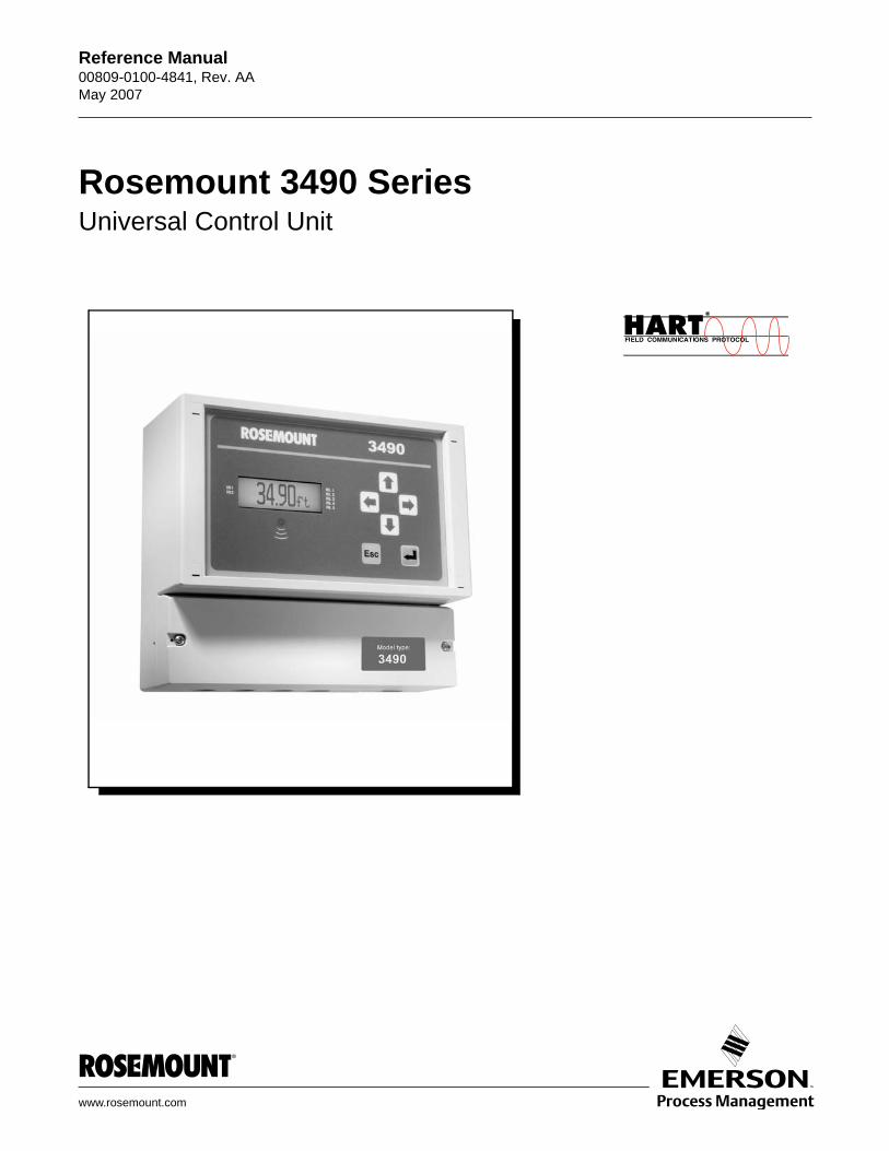
Rosemount 3490 SeriesUniversal Control Unit

Reference Manual 00809-0100-4841, Rev. AA May 2007 Rosemount 3490 Series
www.rosemount.com
Rosemount 3490 SeriesUniversal Control Unit
Rosemount and the Rosemount logotype are registered trademarks of Rosemount Inc.HART is a registered trademark of the HART Communication Foundation.
NOTICE
Read this manual before working with the product. For personal and system safety, and for optimum product performance, make sure you thoroughly understand the contents before installing, using, or maintaining this product.
Within the United States, Rosemount Inc. has two toll-free assistance numbers.
Customer Central: 1-800-999-9307(7:00 a.m. to 7:00 p.m. CST)Technical support, quoting, and order-related questions.
North American Response Center:Equipment service needs.
1-800-654-7768 (24 hours a day – Includes Canada)
For equipment service or support needs outside the United States, contact your local Rosemount representative.
The products described in this document are NOT designed for nuclear-qualified applications.
Using non-nuclear qualified products in applications that require nuclear-qualified hardware or products may cause inaccurate readings.
For information on Rosemount nuclear-qualified products, contact your local Rosemount Sales Representative.
This device complies with part 15 of the FCC rules. Operation is subject to the following two conditions: (1) This device may not cause harmful interference, and (2) this device must accept any interference received, including interference that may cause undesired operation.

Reference Manual 00809-0100-4841, Rev. AA May 2007 Rosemount 3490 Series
www.rosemount.com
Table of ContentsSECTION 1Introduction
Safety Messages . . . . . . . . . . . . . . . . . . . . . . . . . . . . . . . . . . . . . . . . . 1-1Manual Overview . . . . . . . . . . . . . . . . . . . . . . . . . . . . . . . . . . . . . . . . . 1-2Service Support . . . . . . . . . . . . . . . . . . . . . . . . . . . . . . . . . . . . . . . . . . 1-3
SECTION 2Overview
Introduction To The 3490 Series . . . . . . . . . . . . . . . . . . . . . . . . . . . . . 2-1Summary of Features . . . . . . . . . . . . . . . . . . . . . . . . . . . . . . . . . . . 2-1Two mounting options . . . . . . . . . . . . . . . . . . . . . . . . . . . . . . . . . . 2-1Transmitter input. . . . . . . . . . . . . . . . . . . . . . . . . . . . . . . . . . . . . . . 2-2Control functionality . . . . . . . . . . . . . . . . . . . . . . . . . . . . . . . . . . . . 2-2Front Panel . . . . . . . . . . . . . . . . . . . . . . . . . . . . . . . . . . . . . . . . . . . 2-2
Control Unit Functions . . . . . . . . . . . . . . . . . . . . . . . . . . . . . . . . . . . . . 2-3Standard functions (Models 3491/3492/3493) . . . . . . . . . . . . . . . . 2-3Difference, sum and product functions (Model 3492). . . . . . . . . . . 2-3Logging functions (Model 3493) . . . . . . . . . . . . . . . . . . . . . . . . . . . 2-3
Control Unit Front Panel . . . . . . . . . . . . . . . . . . . . . . . . . . . . . . . . . . . 2-4Keypad . . . . . . . . . . . . . . . . . . . . . . . . . . . . . . . . . . . . . . . . . . . . . . 2-4Display . . . . . . . . . . . . . . . . . . . . . . . . . . . . . . . . . . . . . . . . . . . . . . 2-5Status LED . . . . . . . . . . . . . . . . . . . . . . . . . . . . . . . . . . . . . . . . . . . 2-6
SECTION 3Installation
Safety messages . . . . . . . . . . . . . . . . . . . . . . . . . . . . . . . . . . . . . . . . . 3-1Before You Install . . . . . . . . . . . . . . . . . . . . . . . . . . . . . . . . . . . . . . . . 3-2
General considerations. . . . . . . . . . . . . . . . . . . . . . . . . . . . . . . . . . 3-2Mounting the Rosemount 3490 Series Control Unit . . . . . . . . . . . . . . 3-3
Mounting the IP-rated Wall Mount Models . . . . . . . . . . . . . . . . . . . 3-3Mounting the NEMA 4X-rated Wall Mount Models. . . . . . . . . . . . . . . . . . . . . . . . 3-3Mounting Panel Models . . . . . . . . . . . . . . . . . . . . . . . . . . . . . . . . . 3-4
Electrical installation . . . . . . . . . . . . . . . . . . . . . . . . . . . . . . . . . . . . . . 3-6Electrical Connections on Wall Mount Models . . . . . . . . . . . . . . . . 3-6Electrical connections on Panel Mount Model . . . . . . . . . . . . . . . . 3-8Transmitter Connections and Cabling . . . . . . . . . . . . . . . . . . . . . . 3-9Connecting HART Transmitters to 3492. . . . . . . . . . . . . . . . . . . . 3-10Power Connections . . . . . . . . . . . . . . . . . . . . . . . . . . . . . . . . . . . 3-11Earthing Connections . . . . . . . . . . . . . . . . . . . . . . . . . . . . . . . . . . 3-11Relay Connections . . . . . . . . . . . . . . . . . . . . . . . . . . . . . . . . . . . . 3-12Current Output Connections. . . . . . . . . . . . . . . . . . . . . . . . . . . . . 3-12Digital Control Voltage free Contact Inputs . . . . . . . . . . . . . . . . . 3-12RS232 Connections . . . . . . . . . . . . . . . . . . . . . . . . . . . . . . . . . . . 3-13
SECTION 4Getting started
Safety messages . . . . . . . . . . . . . . . . . . . . . . . . . . . . . . . . . . . . . . . . . 4-1Switching on . . . . . . . . . . . . . . . . . . . . . . . . . . . . . . . . . . . . . . . . . . . . 4-2
Switching on the 3491/3493 . . . . . . . . . . . . . . . . . . . . . . . . . . . . . . 4-2Switching-on the 3492 . . . . . . . . . . . . . . . . . . . . . . . . . . . . . . . . . . 4-3
Reference Manual00809-0100-4841, Rev. AA
May 2007Rosemount 3490 Series
1-2
The Hierarchical menu system . . . . . . . . . . . . . . . . . . . . . . . . . . . . . . 4-4How to navigate the menu system . . . . . . . . . . . . . . . . . . . . . . . . . 4-4About parameter screens . . . . . . . . . . . . . . . . . . . . . . . . . . . . . . . . 4-6
Programming . . . . . . . . . . . . . . . . . . . . . . . . . . . . . . . . . . . . . . . . . . . . 4-8Before you begin . . . . . . . . . . . . . . . . . . . . . . . . . . . . . . . . . . . . . . 4-8Comfort (system) settings. . . . . . . . . . . . . . . . . . . . . . . . . . . . . . . 4-11Transmitter inputs to the 3490 . . . . . . . . . . . . . . . . . . . . . . . . . . . . . . . . . . . . . . . . . . 4-12Profile Calculations for Contents and Flow Applications . . . . . . . 4-23Digital Inputs IN1 and IN2. . . . . . . . . . . . . . . . . . . . . . . . . . . . . . . 4-33Logging (3493 Only) . . . . . . . . . . . . . . . . . . . . . . . . . . . . . . . . . . . 4-34Current Output . . . . . . . . . . . . . . . . . . . . . . . . . . . . . . . . . . . . . . . 4-38Relays. . . . . . . . . . . . . . . . . . . . . . . . . . . . . . . . . . . . . . . . . . . . . . 4-39About Alarms . . . . . . . . . . . . . . . . . . . . . . . . . . . . . . . . . . . . . . . . 4-59About Totalising On Model 3491 . . . . . . . . . . . . . . . . . . . . . . . . . 4-62About Totalising on Model 3492 . . . . . . . . . . . . . . . . . . . . . . . . . . 4-63About Totalising on Model 3493 . . . . . . . . . . . . . . . . . . . . . . . . . . 4-64Totalising examples . . . . . . . . . . . . . . . . . . . . . . . . . . . . . . . . . . . 4-67Primary Display Options . . . . . . . . . . . . . . . . . . . . . . . . . . . . . . . . 4-71Serial Communications. . . . . . . . . . . . . . . . . . . . . . . . . . . . . . . . . 4-73PIN Security . . . . . . . . . . . . . . . . . . . . . . . . . . . . . . . . . . . . . . . . . 4-74
SECTION 5Service and Health Checks
Safety messages . . . . . . . . . . . . . . . . . . . . . . . . . . . . . . . . . . . . . . . . . 5-1Servicing . . . . . . . . . . . . . . . . . . . . . . . . . . . . . . . . . . . . . . . . . . . . . . . 5-2Health Checks . . . . . . . . . . . . . . . . . . . . . . . . . . . . . . . . . . . . . . . . . . . 5-2
Health Check: 3490 Series Control Unit. . . . . . . . . . . . . . . . . . . . . 5-2Health Check: Rosemount 3102/3105 Series transmitters. . . . . . . 5-8
APPENDIX AReference Data
Specifications. . . . . . . . . . . . . . . . . . . . . . . . . . . . . . . . . . . . . . . . . . . .A-1Dimensional drawings . . . . . . . . . . . . . . . . . . . . . . . . . . . . . . . . . . . . .A-3Ordering Information . . . . . . . . . . . . . . . . . . . . . . . . . . . . . . . . . . . . . .A-6
Model Code 3491, Standard Control Unit. . . . . . . . . . . . . . . . . . . .A-6Model Code 3492, Differential Control Unit . . . . . . . . . . . . . . . . . .A-7Model Code 3493, Logging Control Unit . . . . . . . . . . . . . . . . . . . .A-8
APPENDIX BProduct Certifications
Safety Messages . . . . . . . . . . . . . . . . . . . . . . . . . . . . . . . . . . . . . . . . .B-1European Directive Information . . . . . . . . . . . . . . . . . . . . . . . . . . . . . .B-2Hazardous Locations Certifications . . . . . . . . . . . . . . . . . . . . . . . . . . .B-3
ATEX Approvals . . . . . . . . . . . . . . . . . . . . . . . . . . . . . . . . . . . . . . .B-3Underwriters Laboratories Inc. (UL) Approvals . . . . . . . . . . . . . . .B-3Canadian Standards Association (CSA) Approvals . . . . . . . . . . . .B-4IECEx Approvals . . . . . . . . . . . . . . . . . . . . . . . . . . . . . . . . . . . . . .B-4
Approval Drawings. . . . . . . . . . . . . . . . . . . . . . . . . . . . . . . . . . . . . . . .B-5
APPENDIX CMenus and Parameters
Menus and parameters . . . . . . . . . . . . . . . . . . . . . . . . . . . . . . . . . . . .C-1
APPENDIX DAdditional Features
Restoring the factory defaults . . . . . . . . . . . . . . . . . . . . . . . . . . . . . . .D-1How to restore the factory default settings . . . . . . . . . . . . . . . . . . .D-1
DIRECT Menu screen . . . . . . . . . . . . . . . . . . . . . . . . . . . . . . . . . . . . .D-2

Reference Manual 000809-0100-4841, Rev. AA May 2007
1-3
Rosemount 3490 Series
APPENDIX ESupport for HART® Transmitters
Overview . . . . . . . . . . . . . . . . . . . . . . . . . . . . . . . . . . . . . . . . . . . . . . .E-1Fully Supported Transmitters. . . . . . . . . . . . . . . . . . . . . . . . . . . . . . . .E-1Universal and Common Practice Commands . . . . . . . . . . . . . . . . . . .E-1
Universal Commands . . . . . . . . . . . . . . . . . . . . . . . . . . . . . . . . . . .E-1Common Practice commands . . . . . . . . . . . . . . . . . . . . . . . . . . . .E-2

Reference Manual00809-0100-4841, Rev. AA
May 2007Rosemount 3490 Series
1-4
Reference Manual 00809-0100-4841, Rev. AA May 2007 Rosemount 3490 Series
www.rosemount.com
Section 1 Introduction
Safety Messages . . . . . . . . . . . . . . . . . . . . . . . . . . . . . . . . . page 1-1Manual Overview . . . . . . . . . . . . . . . . . . . . . . . . . . . . . . . . page 1-2Service Support . . . . . . . . . . . . . . . . . . . . . . . . . . . . . . . . . page 1-3
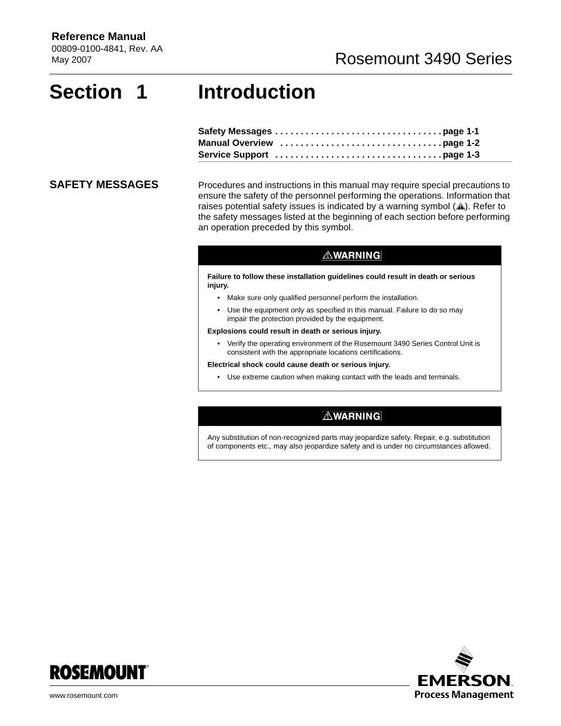
SAFETY MESSAGES Procedures and instructions in this manual may require special precautions to ensure the safety of the personnel performing the operations. Information that raises potential safety issues is indicated by a warning symbol ( ). Refer to the safety messages listed at the beginning of each section before performing an operation preceded by this symbol.
Failure to follow these installation guidelines could result in death or serious injury.
• Make sure only qualified personnel perform the installation.
• Use the equipment only as specified in this manual. Failure to do so may impair the protection provided by the equipment.
Explosions could result in death or serious injury.• Verify the operating environment of the Rosemount 3490 Series Control Unit is
consistent with the appropriate locations certifications.
Electrical shock could cause death or serious injury.• Use extreme caution when making contact with the leads and terminals.
Any substitution of non-recognized parts may jeopardize safety. Repair, e.g. substitution of components etc., may also jeopardize safety and is under no circumstances allowed.
Reference Manual00809-0100-4841, Rev. AA
May 2007Rosemount 3490 Series
1-2
MANUAL OVERVIEW This manual provides installation, configuration and maintenance information for the Rosemount 3490 Series Control Unit.
Section 2: Overview
Section 3: Installation
Section 4: Getting Started
Section 5: Service and Health Checks
Appendix A: Reference Data
Appendix B: Product Certifications
Appendix C: Menus and Parameters
Appendix D: Additional Features
Appendix E: Support for HART® Transmitters
1-3
Rosemount 3490 SeriesReference Manual 00809-0100-4841, Rev. AA May 2007
SERVICE SUPPORT To expedite the return process outside of the United States, contact the nearest Rosemount representative.
Within the United States, call the Rosemount National Response Center using the 1-800-654-RSMT (7768) toll-free number. This center, available 24 hours a day, will assist you with any needed information or materials.
The center will ask for product model and serial numbers, and will provide a Return Material Authorization (RMA) number. The center will also ask for the process material to which the product was last exposed.
Rosemount National Response Center representatives will explain the additional information and procedures necessary to return goods exposed to hazardous substances. This can avoid injury if they are informed of and understand the hazard. If the product being returned was exposed to a hazardous substance as defined by OSHA, a copy of the required Material Safety Data Sheet (MSDS) for each hazardous substance identified must be included with the returned goods.

Reference Manual00809-0100-4841, Rev. AA
May 2007Rosemount 3490 Series
1-4
Reference Manual 00809-0100-4841, Rev. AA May 2007 Rosemount 3490 Series
www.rosemount.com
Section 2 Overview
Introduction To The 3490 Series . . . . . . . . . . . . . . . . . . . . page 2-1Control Unit Functions . . . . . . . . . . . . . . . . . . . . . . . . . . . . page 2-3Control Unit Front Panel . . . . . . . . . . . . . . . . . . . . . . . . . . page 2-4
INTRODUCTION TO THE 3490 SERIES
The Rosemount 3490 Series is a range of control units, providing a wide range of control functions and display of the measured variable.
Summary of Features • Full support for Rosemount 3100 Series ultrasonic transmitters.• Intrinsically Safe power supply to transmitters.• 4-line LCD display with back light - for text and graphics.• 6-button keypad - for local interrogation and programming.• Intuitive menu system.• 4-20mA / HART input.• Two digital inputs.• 5 relay outputs.• Isolated 4-20mA output.• LED indicator for system health.
Two mounting options There are two mounting versions of the control unit available:• Wall mounted.• Panel mounted.
The wall mounting version has a tough rated housing for installation indoors or outdoors, whilst the panel mounting version is for installation in a control room panel/cabinet.
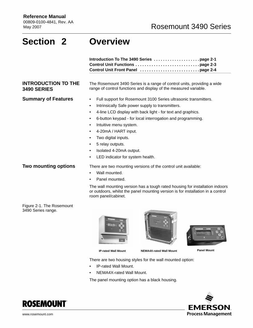
Figure 2-1. The Rosemount 3490 Series range.
There are two housing styles for the wall mounted option:• IP-rated Wall Mount.• NEMA4X-rated Wall Mount.
The panel mounting option has a black housing.
IP-rated Wall Mount NEMA4X-rated Wall Mount Panel Mount
Reference Manual00809-0100-4841, Rev. AA
May 2007Rosemount 3490 Series
2-2
Transmitter input The Control Unit will accept input from a 4-20mA / HART transmitter. Model 3492 will accept inputs from two HART transmitters.
NOTEThe Rosemount 3490 Series is designed for non-hazardous (safe) area installation, but can be connected to a transmitter installed in a hazardous area. For certifications of the Control Unit, see Appendix B.
Control functionality Control functionality is provided by five SPCO voltage-free contact relays in the control unit. There is also an isolated 4-20mA signal output.
For applications where the functionality of the control unit is linked to other external events, the two digital input ports will accept contact closure signals.
Front Panel The Rosemount 3490 Series is programmed simply using the 6-button membrane keypad on the front panel. Menu structured programming is employed, with the display assisting the user with dynamic help text.
A full specification for the control unit is in Appendix A.
Reference Manual 00809-0100-4841, Rev. AA May 2007
2-3
Rosemount 3490 Series
CONTROL UNIT FUNCTIONS
For a full guide to programming the Rosemount 3490 Series Control Unit, see “Programming” on page 4-9.
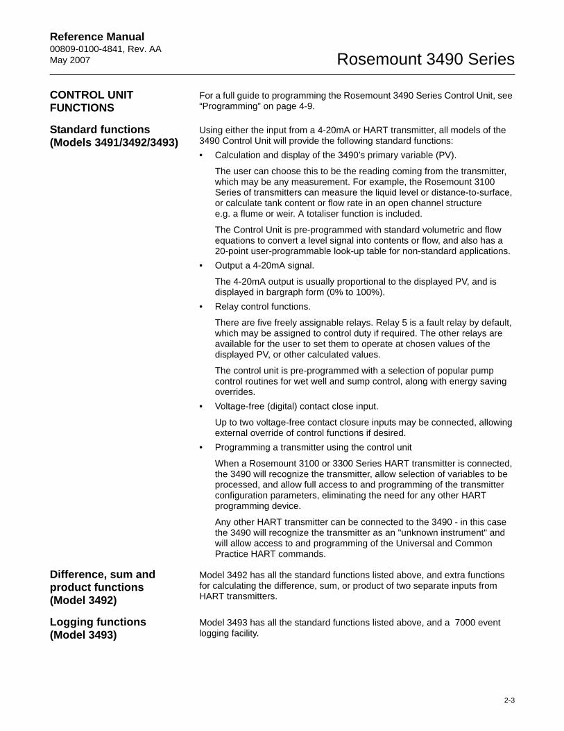
Standard functions(Models 3491/3492/3493)
Using either the input from a 4-20mA or HART transmitter, all models of the 3490 Control Unit will provide the following standard functions:• Calculation and display of the 3490’s primary variable (PV).
The user can choose this to be the reading coming from the transmitter, which may be any measurement. For example, the Rosemount 3100 Series of transmitters can measure the liquid level or distance-to-surface, or calculate tank content or flow rate in an open channel structure e.g. a flume or weir. A totaliser function is included.
The Control Unit is pre-programmed with standard volumetric and flow equations to convert a level signal into contents or flow, and also has a 20-point user-programmable look-up table for non-standard applications.
• Output a 4-20mA signal.
The 4-20mA output is usually proportional to the displayed PV, and is displayed in bargraph form (0% to 100%).
• Relay control functions.
There are five freely assignable relays. Relay 5 is a fault relay by default, which may be assigned to control duty if required. The other relays are available for the user to set them to operate at chosen values of the displayed PV, or other calculated values.
The control unit is pre-programmed with a selection of popular pump control routines for wet well and sump control, along with energy saving overrides.
• Voltage-free (digital) contact close input.
Up to two voltage-free contact closure inputs may be connected, allowing external override of control functions if desired.
• Programming a transmitter using the control unit
When a Rosemount 3100 or 3300 Series HART transmitter is connected, the 3490 will recognize the transmitter, allow selection of variables to be processed, and allow full access to and programming of the transmitter configuration parameters, eliminating the need for any other HART programming device.
Any other HART transmitter can be connected to the 3490 - in this case the 3490 will recognize the transmitter as an "unknown instrument" and will allow access to and programming of the Universal and Common Practice HART commands.
Difference, sum and product functions(Model 3492)
Model 3492 has all the standard functions listed above, and extra functions for calculating the difference, sum, or product of two separate inputs from HART transmitters.
Logging functions (Model 3493)
Model 3493 has all the standard functions listed above, and a 7000 event logging facility.
Reference Manual00809-0100-4841, Rev. AA
May 2007Rosemount 3490 Series
2-4
CONTROL UNIT FRONT PANEL
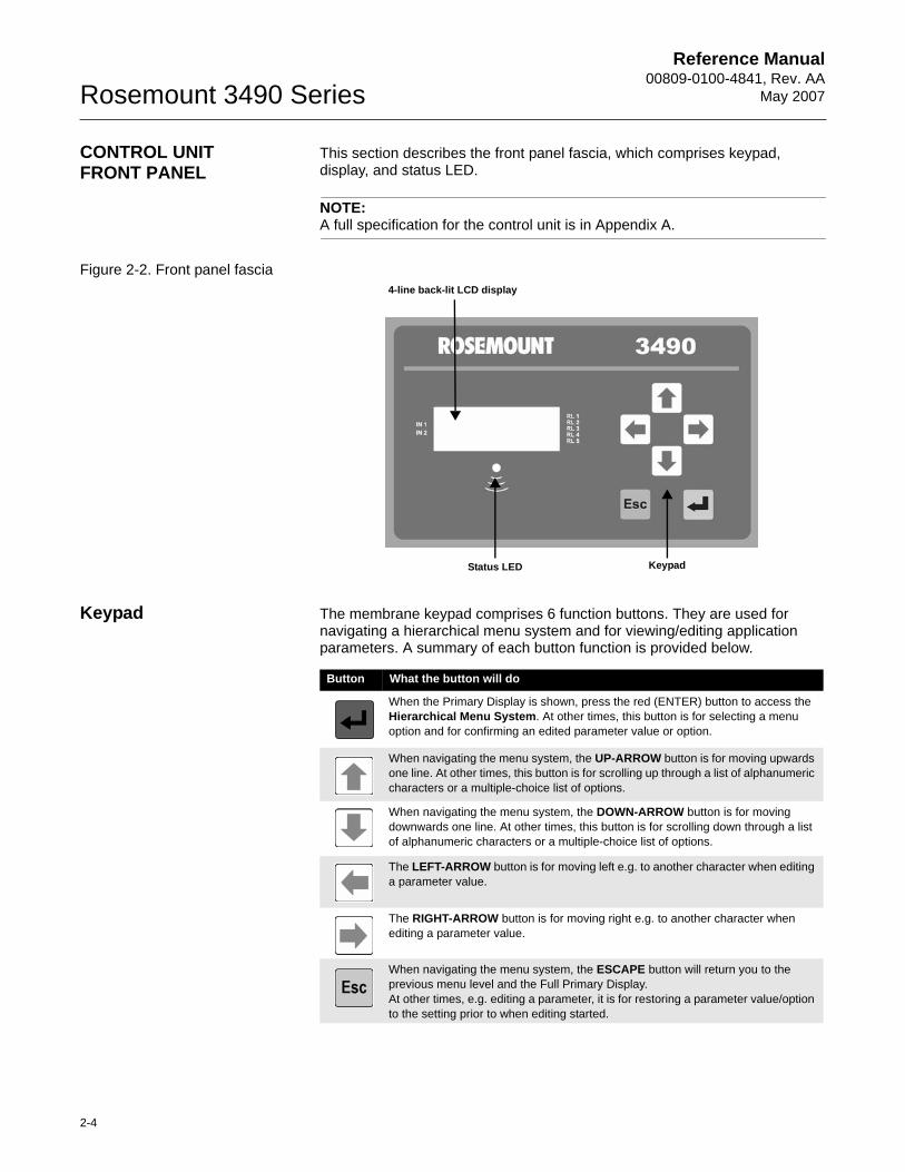
This section describes the front panel fascia, which comprises keypad, display, and status LED.
NOTE:A full specification for the control unit is in Appendix A.
Figure 2-2. Front panel fascia
Keypad The membrane keypad comprises 6 function buttons. They are used for navigating a hierarchical menu system and for viewing/editing application parameters. A summary of each button function is provided below.
4-line back-lit LCD display
Status LED Keypad
Button What the button will do
When the Primary Display is shown, press the red (ENTER) button to access the Hierarchical Menu System. At other times, this button is for selecting a menu option and for confirming an edited parameter value or option.
When navigating the menu system, the UP-ARROW button is for moving upwards one line. At other times, this button is for scrolling up through a list of alphanumeric characters or a multiple-choice list of options.
When navigating the menu system, the DOWN-ARROW button is for moving downwards one line. At other times, this button is for scrolling down through a list of alphanumeric characters or a multiple-choice list of options.
The LEFT-ARROW button is for moving left e.g. to another character when editing a parameter value.
The RIGHT-ARROW button is for moving right e.g. to another character when editing a parameter value.
When navigating the menu system, the ESCAPE button will return you to the previous menu level and the Full Primary Display.At other times, e.g. editing a parameter, it is for restoring a parameter value/option to the setting prior to when editing started.
Reference Manual 00809-0100-4841, Rev. AA May 2007
2-5
Rosemount 3490 Series
Display The LCD display shows both text and graphical information. After the power-up and self-checks are completed, the Primary Display is presented.
The default display typically features a digital clock, measured variable with display units, and status icons.
There are some display differences between the models:• On models 3491 and 3492, a bar graph represents the 4-20mA output
signal. (Model 3493 display can be programmed to show the bar graph.)• On model 3492, there are extra graphics relating to having two
transmitters connected to the control unit.• On model 3493, there are two totalisers displayed; one above and one
below the measured variable.
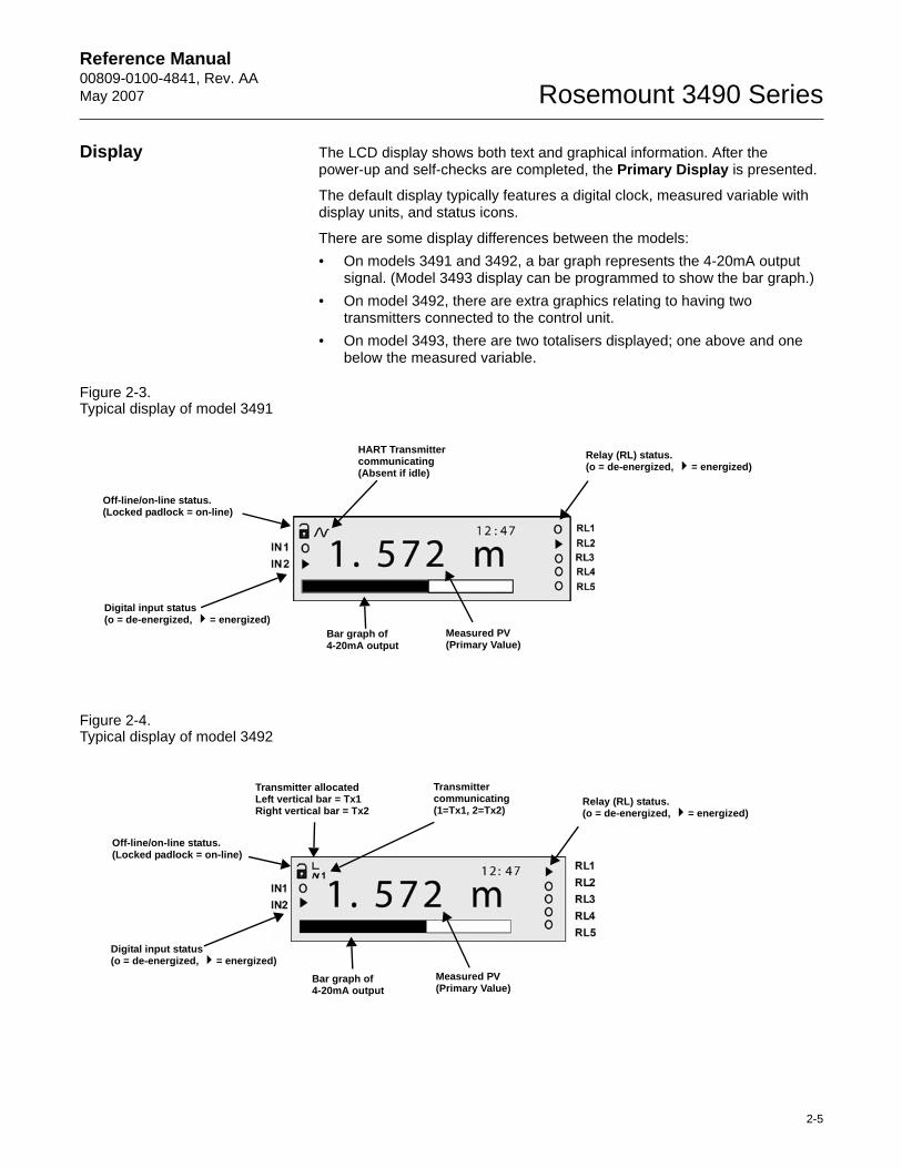
Figure 2-3. Typical display of model 3491
Figure 2-4. Typical display of model 3492
HART Transmittercommunicating(Absent if idle)
Measured PV (Primary Value)
Bar graph of 4-20mA output
Off-line/on-line status. (Locked padlock = on-line)
Relay (RL) status.(o = de-energized, = energized)
Digital input status(o = de-energized, = energized)
Transmitter allocatedLeft vertical bar = Tx1Right vertical bar = Tx2
Transmittercommunicating(1=Tx1, 2=Tx2)
Measured PV(Primary Value)
Bar graph of 4-20mA output
Off-line/on-line status.(Locked padlock = on-line)
Relay (RL) status.(o = de-energized, = energized)
Digital input status(o = de-energized, = energized)
Reference Manual00809-0100-4841, Rev. AA
May 2007Rosemount 3490 Series
2-6
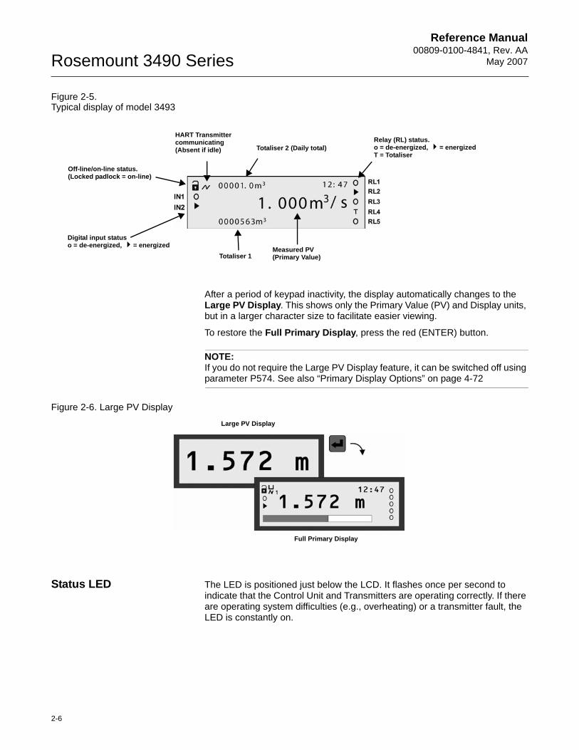
Figure 2-5. Typical display of model 3493
After a period of keypad inactivity, the display automatically changes to the Large PV Display. This shows only the Primary Value (PV) and Display units, but in a larger character size to facilitate easier viewing.
To restore the Full Primary Display, press the red (ENTER) button.
NOTE:If you do not require the Large PV Display feature, it can be switched off using parameter P574. See also “Primary Display Options” on page 4-72
Figure 2-6. Large PV Display
Status LED The LED is positioned just below the LCD. It flashes once per second to indicate that the Control Unit and Transmitters are operating correctly. If there are operating system difficulties (e.g., overheating) or a transmitter fault, the LED is constantly on.
HART Transmittercommunicating(Absent if idle)
Measured PV (Primary Value)Totaliser 1
Off-line/on-line status.(Locked padlock = on-line)
Relay (RL) status.o = de-energized, = energizedT = Totaliser
Totaliser 2 (Daily total)
Digital input statuso = de-energized, = energized
Full Primary Display
Large PV Display
Reference Manual 00809-0100-4841, Rev. AA May 2007 Rosemount 3490 Series
www.rosemount.com
Section 3 Installation
Safety messages . . . . . . . . . . . . . . . . . . . . . . . . . . . . . . . . . page 3-1Before You Install . . . . . . . . . . . . . . . . . . . . . . . . . . . . . . . . page 3-2Mounting the Rosemount 3490 Series Control Unit . . . . page 3-3Electrical installation . . . . . . . . . . . . . . . . . . . . . . . . . . . . . page 3-6
SAFETY MESSAGES Procedures and instructions in this section may require special precautions to ensure the safety of the personnel performing the operations. Information that raises potential safety issues is indicated by a warning symbol ( ). Please refer to the following safety messages before performing an operation preceded by this symbol.
Explosions could result in death or serious injury:Verify that the operating environment is consistent with the appropriate locations certifications (see Appendix B).
Do not remove the housing cover in explosive atmospheres when the circuit is alive.
Failure to follow safe installation and servicing guidelines could result in death or serious injury:Make sure only qualified personnel perform the installation.
Use the equipment only as specified in this manual. Failure to do so may impair the protection provided by the equipment.
Do not perform any service other than those contained in this manual unless you are qualified.
High voltage that may be present on leads could cause electrical shock:Avoid contact with leads and terminals.
Make sure the main power to the Rosemount 3490 Series is off, and the lines to any other external power source are disconnected or not powered while wiring.
Reference Manual00809-0100-4841, Rev. AA
May 2007Rosemount 3490 Series
3-2
BEFORE YOU INSTALL The Rosemount 3490 Series Control Unit may be connected to a transmitter located in a hazardous area. The Control Unit must not itself be located in a hazardous area.
General considerations • Do not mount the Control Unit on a structure that is subject to vibration, or in a position where damage may be caused by impact, thermal stress or liquid ingress.
• The fuse must only be replaced with the type specified.• If the equipment is likely to come into contact with aggressive substances,
it is the responsibility of the user to take suitable precautions that prevent it from being adversely affected, thus ensuring that the type of protection is not compromised.
Aggressive Substances - e.g. acidic liquids or gases that may attack metals or solvents that may affect polymeric materials.
Suitable Precautions - e.g. regular checks as part of routine inspections or establishing from the material's data sheet that it is resistant to specific chemicals.
• The user should not repair this equipment.• Terminal 30 (Intrinsically Safe Earth) of the Control Unit must be
connected to a High Integrity Earth.• A mains powered Control Unit must not be connected to a supply
exceeding 250V r.m.s. or dc, or to apparatus containing a source of voltage exceeding 250V r.m.s. or dc.
• A dc powered Control Unit must not be connected to a supply exceeding 30V dc, or to apparatus containing a source of voltage exceeding 30V dc.
• The Intrinsically Safe outputs of the Control Unit may be connected to certified equipment used in a hazardous area. Refer to Appendix B for details of relevant certifications.
• Refer to the technical data in Appendix A.
Reference Manual 00809-0100-4841, Rev. AA May 2007
3-3
Rosemount 3490 Series
MOUNTING THE ROSEMOUNT 3490 SERIES CONTROL UNIT
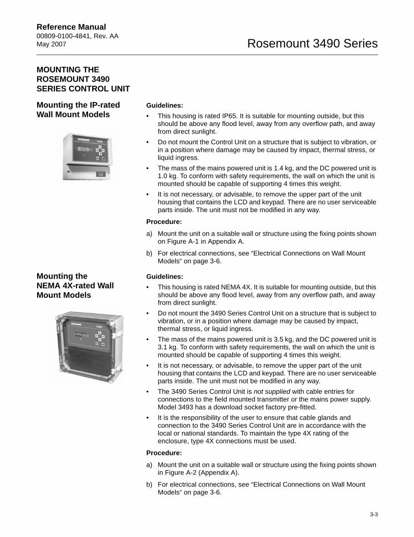
Mounting the IP-rated Wall Mount Models
Guidelines:• This housing is rated IP65. It is suitable for mounting outside, but this
should be above any flood level, away from any overflow path, and away from direct sunlight.
• Do not mount the Control Unit on a structure that is subject to vibration, or in a position where damage may be caused by impact, thermal stress, or liquid ingress.
• The mass of the mains powered unit is 1.4 kg, and the DC powered unit is 1.0 kg. To conform with safety requirements, the wall on which the unit is mounted should be capable of supporting 4 times this weight.
• It is not necessary, or advisable, to remove the upper part of the unit housing that contains the LCD and keypad. There are no user serviceable parts inside. The unit must not be modified in any way.
Procedure:
a) Mount the unit on a suitable wall or structure using the fixing points shown on Figure A-1 in Appendix A.
b) For electrical connections, see “Electrical Connections on Wall Mount Models“ on page 3-6.
Mounting the NEMA 4X-rated Wall Mount Models
Guidelines:• This housing is rated NEMA 4X. It is suitable for mounting outside, but this
should be above any flood level, away from any overflow path, and away from direct sunlight.
• Do not mount the 3490 Series Control Unit on a structure that is subject to vibration, or in a position where damage may be caused by impact, thermal stress, or liquid ingress.
• The mass of the mains powered unit is 3.5 kg, and the DC powered unit is 3.1 kg. To conform with safety requirements, the wall on which the unit is mounted should be capable of supporting 4 times this weight.
• It is not necessary, or advisable, to remove the upper part of the unit housing that contains the LCD and keypad. There are no user serviceable parts inside. The unit must not be modified in any way.
• The 3490 Series Control Unit is not supplied with cable entries for connections to the field mounted transmitter or the mains power supply. Model 3493 has a download socket factory pre-fitted.
• It is the responsibility of the user to ensure that cable glands and connection to the 3490 Series Control Unit are in accordance with the local or national standards. To maintain the type 4X rating of the enclosure, type 4X connections must be used.
Procedure:
a) Mount the unit on a suitable wall or structure using the fixing points shown in Figure A-2 (Appendix A).
b) For electrical connections, see “Electrical Connections on Wall Mount Models“ on page 3-6.
Reference Manual00809-0100-4841, Rev. AA
May 2007Rosemount 3490 Series
3-4
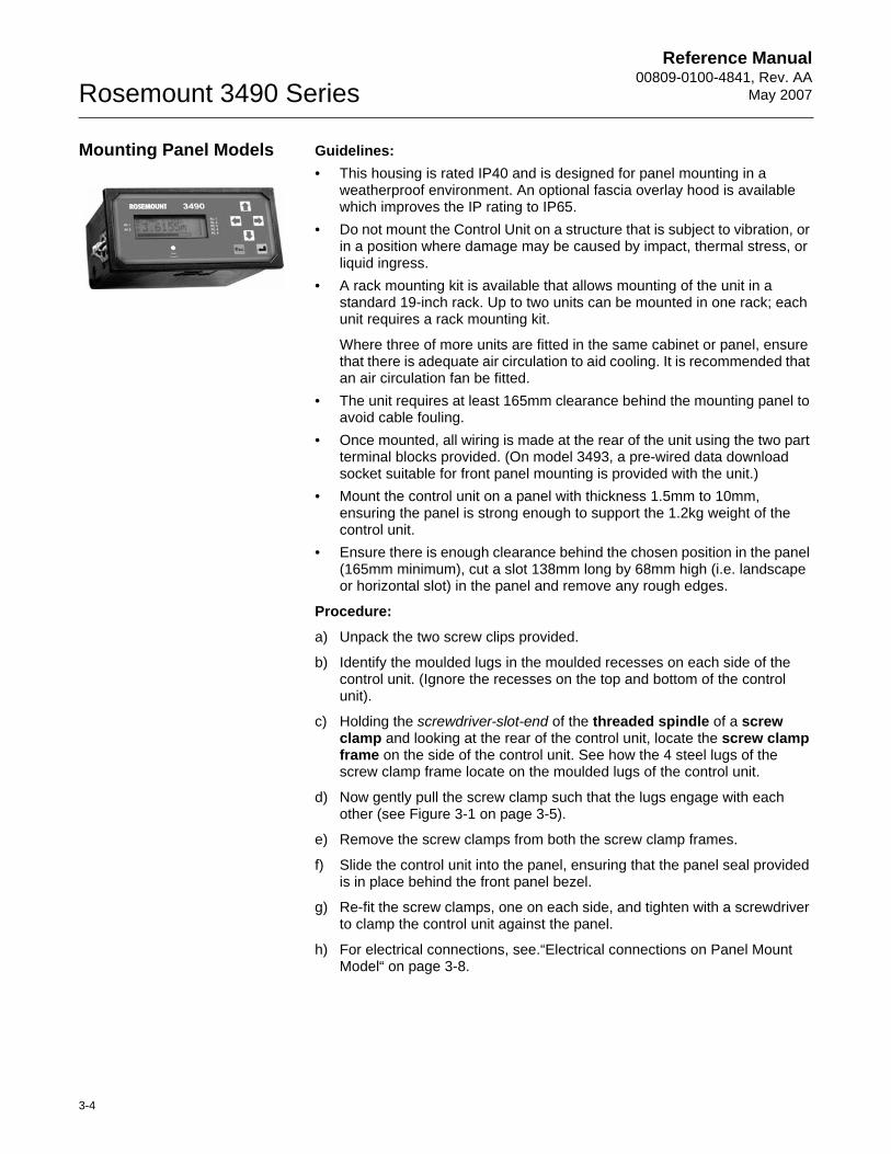
Mounting Panel Models Guidelines:• This housing is rated IP40 and is designed for panel mounting in a
weatherproof environment. An optional fascia overlay hood is available which improves the IP rating to IP65.
• Do not mount the Control Unit on a structure that is subject to vibration, or in a position where damage may be caused by impact, thermal stress, or liquid ingress.
• A rack mounting kit is available that allows mounting of the unit in a standard 19-inch rack. Up to two units can be mounted in one rack; each unit requires a rack mounting kit.
Where three of more units are fitted in the same cabinet or panel, ensure that there is adequate air circulation to aid cooling. It is recommended that an air circulation fan be fitted.
• The unit requires at least 165mm clearance behind the mounting panel to avoid cable fouling.
• Once mounted, all wiring is made at the rear of the unit using the two part terminal blocks provided. (On model 3493, a pre-wired data download socket suitable for front panel mounting is provided with the unit.)
• Mount the control unit on a panel with thickness 1.5mm to 10mm, ensuring the panel is strong enough to support the 1.2kg weight of the control unit.
• Ensure there is enough clearance behind the chosen position in the panel (165mm minimum), cut a slot 138mm long by 68mm high (i.e. landscape or horizontal slot) in the panel and remove any rough edges.
Procedure:
a) Unpack the two screw clips provided.
b) Identify the moulded lugs in the moulded recesses on each side of the control unit. (Ignore the recesses on the top and bottom of the control unit).
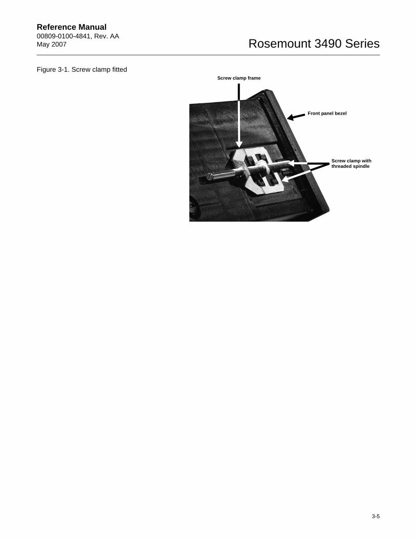
c) Holding the screwdriver-slot-end of the threaded spindle of a screw clamp and looking at the rear of the control unit, locate the screw clamp frame on the side of the control unit. See how the 4 steel lugs of the screw clamp frame locate on the moulded lugs of the control unit.
d) Now gently pull the screw clamp such that the lugs engage with each other (see Figure 3-1 on page 3-5).
e) Remove the screw clamps from both the screw clamp frames.
f) Slide the control unit into the panel, ensuring that the panel seal provided is in place behind the front panel bezel.
g) Re-fit the screw clamps, one on each side, and tighten with a screwdriver to clamp the control unit against the panel.
h) For electrical connections, see.“Electrical connections on Panel Mount Model“ on page 3-8.
Reference Manual 00809-0100-4841, Rev. AA May 2007
3-5
Rosemount 3490 Series
Figure 3-1. Screw clamp fitted
Screw clamp with threaded spindle
Front panel bezel
Screw clamp frame
Reference Manual00809-0100-4841, Rev. AA
May 2007Rosemount 3490 Series
3-6
ELECTRICAL INSTALLATION
Electrical Connections on Wall Mount Models
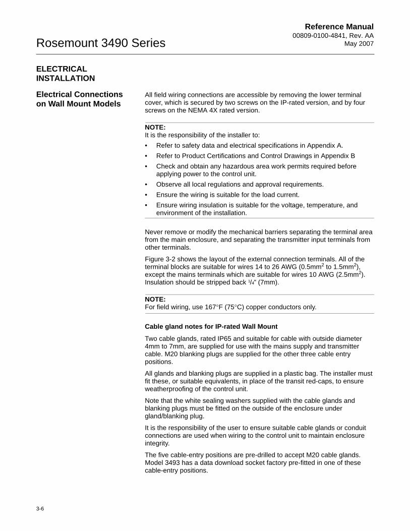
All field wiring connections are accessible by removing the lower terminal cover, which is secured by two screws on the IP-rated version, and by four screws on the NEMA 4X rated version.
NOTE:It is the responsibility of the installer to:• Refer to safety data and electrical specifications in Appendix A.• Refer to Product Certifications and Control Drawings in Appendix B• Check and obtain any hazardous area work permits required before
applying power to the control unit.• Observe all local regulations and approval requirements.• Ensure the wiring is suitable for the load current.• Ensure wiring insulation is suitable for the voltage, temperature, and
environment of the installation.
Never remove or modify the mechanical barriers separating the terminal area from the main enclosure, and separating the transmitter input terminals from other terminals.
Figure 3-2 shows the layout of the external connection terminals. All of the terminal blocks are suitable for wires 14 to 26 AWG (0.5mm2 to 1.5mm2), except the mains terminals which are suitable for wires 10 AWG (2.5mm2). Insulation should be stripped back 1/4” (7mm).
NOTE:For field wiring, use 167°F (75°C) copper conductors only.
Cable gland notes for IP-rated Wall Mount
Two cable glands, rated IP65 and suitable for cable with outside diameter 4mm to 7mm, are supplied for use with the mains supply and transmitter cable. M20 blanking plugs are supplied for the other three cable entry positions.
All glands and blanking plugs are supplied in a plastic bag. The installer must fit these, or suitable equivalents, in place of the transit red-caps, to ensure weatherproofing of the control unit.
Note that the white sealing washers supplied with the cable glands and blanking plugs must be fitted on the outside of the enclosure under gland/blanking plug.
It is the responsibility of the user to ensure suitable cable glands or conduit connections are used when wiring to the control unit to maintain enclosure integrity.
The five cable-entry positions are pre-drilled to accept M20 cable glands. Model 3493 has a data download socket factory pre-fitted in one of these cable-entry positions.
Reference Manual 00809-0100-4841, Rev. AA May 2007
3-7
Rosemount 3490 Series
Cable gland and conduit notes for NEMA4X-rated Wall Mount
It is the responsibility of the user to ensure suitable cable glands or conduit connections are used when wiring to the 3490 Series Control Unit to maintain the enclosure integrity.
Protective earth cables must be connected to at least one of the bonding points on the inside of the enclosure. Bonding between conduit entries is not automatic and must be provided as part of the installation.
Model 3493 has a data download socket factory pre-fitted.
NOTE:In Intrinsically Safe systems, apparatus connected to the 3490 Series Control Unit must not be supplied from a voltage greater than 250V r.m.s. or 250V dc.
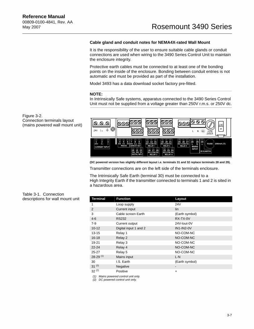
Figure 3-2. Connection terminals layout (mains powered wall mount unit)
(DC powered version has slightly different layout i.e. terminals 31 and 32 replace terminals 28 and 29).
Transmitter connections are on the left side of the terminals enclosure.
The Intrinsically Safe Earth (terminal 30) must be connected to aHigh Integrity Earth if the transmitter connected to terminals 1 and 2 is sited in a hazardous area.
Table 3-1. Connection descriptions for wall mount unit
10 11 120VIN2IN1
7 8 924V Iout 0V
4 5 6RX TX 0V
13
16
14
17
15
18
NO COM NC
NCCOMNO
25 26 27NO COM NC
19
22
20
23
21
24
NO COM NC
NCCOMNO
124V Iin
2 3FUSE 200mA (T)
28L N
29 30
IS EARTH
Terminal Function Layout1 Loop supply 24V2 Current input Iin3 Cable screen Earth (Earth symbol)4-6 RS232 RX-TX-0V7-9 Current output 24V-Iout-0V10-12 Digital input 1 and 2 IN1-IN2-0V13-15 Relay 1 NO-COM-NC16-18 Relay 2 NO-COM-NC19-21 Relay 3 NO-COM-NC22-24 Relay 4 NO-COM-NC25-27 Relay 5 NO-COM-NC28-29 (1)
(1) Mains powered control unit only.
Mains input L-N 30 I.S. Earth (Earth symbol)31 (2)
(2) DC powered control unit only.
Negative - 32 (2) Positive +
Reference Manual00809-0100-4841, Rev. AA
May 2007Rosemount 3490 Series
3-8
Electrical connections on Panel Mount Model
All connections are made to the rear of the control unit using the two part terminal connectors provided.
NOTE
It is the responsibility of the installer to:• Refer to safety data and electrical specifications in Appendix A.• Refer to Product Certifications and Control Drawings in Appendix B• Observe all local regulations and approval requirements.• Check and obtain any hazardous area work permits required before
applying power to the control unit.• Ensure the wiring is suitable for the load current.• Ensure wiring insulation is suitable for the voltage, temperature, and
environment of the installation.
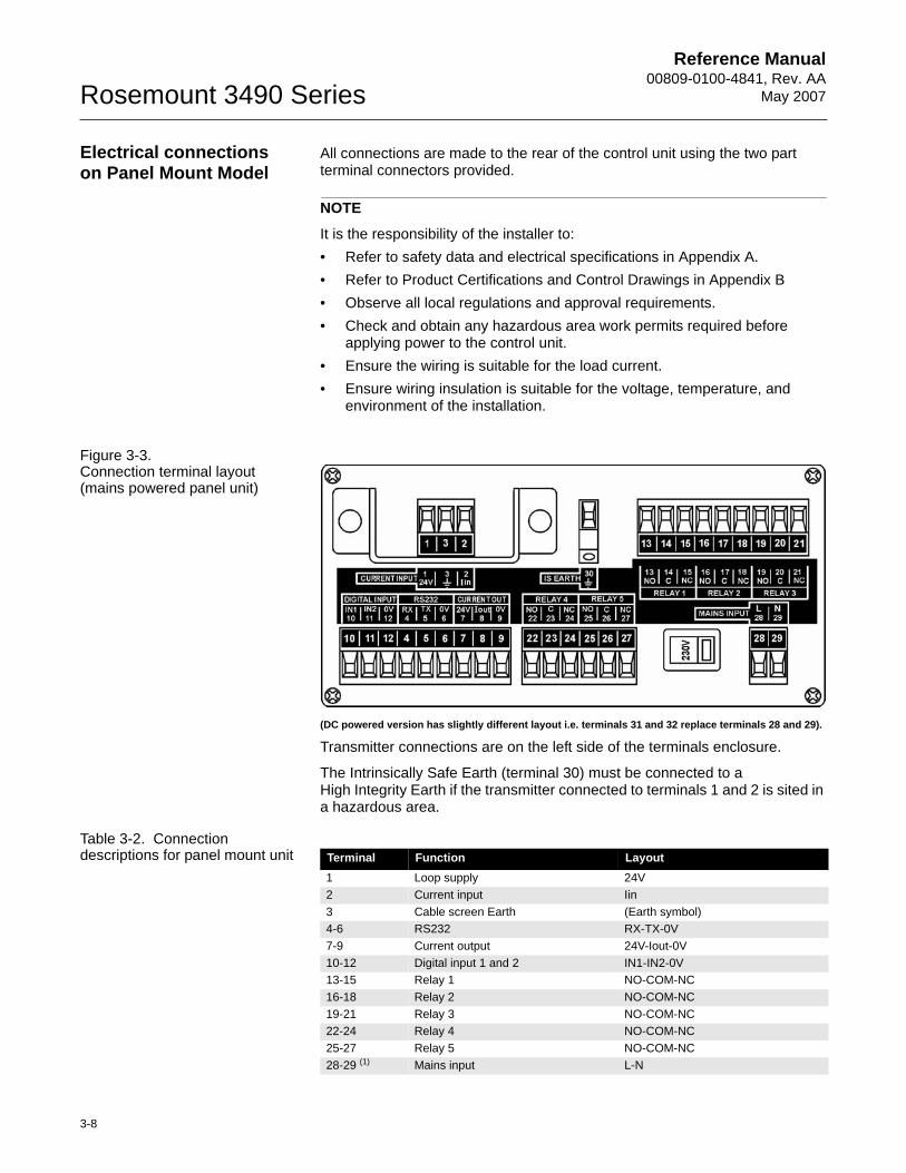
Figure 3-3. Connection terminal layout (mains powered panel unit)
(DC powered version has slightly different layout i.e. terminals 31 and 32 replace terminals 28 and 29).
Transmitter connections are on the left side of the terminals enclosure.
The Intrinsically Safe Earth (terminal 30) must be connected to aHigh Integrity Earth if the transmitter connected to terminals 1 and 2 is sited in a hazardous area.
Table 3-2. Connection descriptions for panel mount unit Terminal Function Layout
1 Loop supply 24V2 Current input Iin3 Cable screen Earth (Earth symbol)4-6 RS232 RX-TX-0V7-9 Current output 24V-Iout-0V10-12 Digital input 1 and 2 IN1-IN2-0V13-15 Relay 1 NO-COM-NC16-18 Relay 2 NO-COM-NC19-21 Relay 3 NO-COM-NC22-24 Relay 4 NO-COM-NC25-27 Relay 5 NO-COM-NC28-29 (1) Mains input L-N
Reference Manual 00809-0100-4841, Rev. AA May 2007
3-9
Rosemount 3490 Series
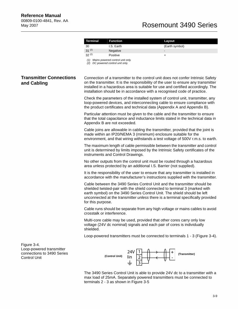
Transmitter Connections and Cabling
Connection of a transmitter to the control unit does not confer Intrinsic Safety on the transmitter. It is the responsibility of the user to ensure any transmitter installed in a hazardous area is suitable for use and certified accordingly. The installation should be in accordance with a recognised code of practice.
Check the parameters of the installed system of control unit, transmitter, any loop-powered devices, and interconnecting cable to ensure compliance with the product certificates and technical data (Appendix A and Appendix B).
Particular attention must be given to the cable and the transmitter to ensure that the total capacitance and inductance limits stated in the technical data in Appendix B are not exceeded.
Cable joins are allowable in cabling the transmitter, provided that the joint is made within an IP20/NEMA 3 (minimum) enclosure suitable for the environment, and that wiring withstands a test voltage of 500V r.m.s. to earth.
The maximum length of cable permissible between the transmitter and control unit is determined by limits imposed by the Intrinsic Safety certificates of the instruments and Control Drawings.
No other outputs from the control unit must be routed through a hazardous area unless protected by an additional I.S. Barrier (not supplied).
It is the responsibility of the user to ensure that any transmitter is installed in accordance with the manufacturer’s instructions supplied with the transmitter.
Cable between the 3490 Series Control Unit and the transmitter should be shielded twisted-pair with the shield connected to terminal 3 (marked with earth symbol) on the 3490 Series Control Unit. The shield should be left unconnected at the transmitter unless there is a terminal specifically provided for this purpose.
Cable runs should be separate from any high voltage or mains cables to avoid crosstalk or interference.
Multi-core cable may be used, provided that other cores carry only low voltage (24V dc nominal) signals and each pair of cores is individually shielded.
Loop-powered transmitters must be connected to terminals 1 - 3 (Figure 3-4).
Figure 3-4. Loop-powered transmitter connections to 3490 Series Control Unit
The 3490 Series Control Unit is able to provide 24V dc to a transmitter with a max load of 25mA. Separately powered transmitters must be connected to terminals 2 - 3 as shown in Figure 3-5
30 I.S. Earth (Earth symbol)31 (2) Negative - 32 (2) Positive + (1) Mains powered control unit only.(2) DC powered control unit only.
Terminal Function Layout
123
24VIin(Control Unit)
(Transmitter)
Reference Manual00809-0100-4841, Rev. AA
May 2007Rosemount 3490 Series
3-10
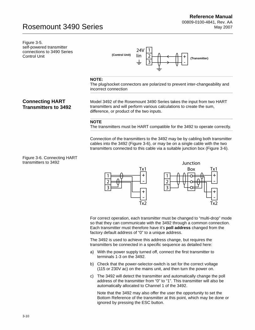
Figure 3-5. self-powered transmitter connections to 3490 Series Control Unit
NOTE:The plug/socket connectors are polarized to prevent inter-changeability and incorrect connection
Connecting HART Transmitters to 3492
Model 3492 of the Rosemount 3490 Series takes the input from two HART transmitters and will perform various calculations to create the sum, difference, or product of the two inputs.
NOTEThe transmitters must be HART compatible for the 3492 to operate correctly.
Connection of the transmitters to the 3492 may be by cabling both transmitter cables into the 3492 (Figure 3-6), or may be on a single cable with the two transmitters connected to this cable via a suitable junction box (Figure 3-6).
Figure 3-6. Connecting HART transmitters to 3492
For correct operation, each transmitter must be changed to “multi-drop” mode so that they can communicate with the 3492 through a common connection. Each transmitter must therefore have it’s poll address changed from the factory default address of “0” to a unique address.
The 3492 is used to achieve this address change, but requires the transmitters be connected in a specific sequence as detailed here:
a) With the power supply turned off, connect the first transmitter toterminals 1-3 on the 3492.
b) Check that the power-selector-switch is set for the correct voltage(115 or 230V ac) on the mains unit, and then turn the power on.
c) The 3492 will detect the transmitter and automatically change the poll address of the transmitter from “0” to “1”. This transmitter will also be automatically allocated to Channel 1 of the 3492.
Note that the 3492 may also offer the user the opportunity to set the Bottom Reference of the transmitter at this point, which may be done or ignored by pressing the ESC button.
123
24VIin(Control Unit)
(Transmitter)
123
Tx1
Tx2
123
Tx1
Tx2
JunctionBox
Reference Manual 00809-0100-4841, Rev. AA May 2007
3-11
Rosemount 3490 Series
d) Turn the power supply off and connect the second transmitter, either at the same terminals 1-3 as the first transmitter or at the junction box, such that both transmitters are now connected.
e) Turn the power supply on. The 3492 will once again search for and detect connected transmitters. After the second transmitter is found, the 3492 will automatically change the poll address from “0” to “2”. The second transmitter will also be automatically allocated to Channel 2 of the 3492.
Note that the 3492 may also offer the user the opportunity to set the Bottom Reference of the transmitter at this point, which may be done or ignored by press the ESC button.
Power Connections If the 3490 Series Control Unit is powered by mains AC power, select the AC voltage as 115V or 230V using the voltage-selector slide switch.
If the 3490 Series Control Unit is DC powered, ensure the supply is adequate (15 - 30V dc). Do not exceed 30V dc.
A switch or circuit breaker should be installed in close proximity to the instrument, and labelled as such.
Although the 3490 Series Control Unit meets all European standards for surge immunity on power and signal lines, it is recommended that lightning suppressors, such as made by Telematic Limited, are fitted if local conditions make this advisable.
Earthing Connections The IP-rated Rosemount 3490 Series of Control Units are double insulated and DO NOT require a mains earth.
DO NOT connect a mains earth to terminal 30.
Terminal 30 is provided for use as an Intrinsically Safe (or functional) earth connection, which MUST be used when a transmitter is mounted in a hazardous area and is connected to terminals 1 and 2.
Terminal 3 is to be used for connection of the shield of the twisted-pair transmitter cable when the 3490 Series Control Unit is powering the transmitter (as in Figure 3-4 on page 3-9). Note that this shield should be left unconnected at the transmitter end unless there is a terminal provided for this purpose.
On the NEMA4X-rated Control Unit, protective earth cables must be connected to at least one of the bonding points on the inside of the enclosure. Bonding between conduit entries is not automatic and must be provided as part of the installation.
When connected to equipment located in a hazardous area, not meeting the requirements of clause 6.3.12 (Isolation of circuits from earth or frame) in IEC 60079-11:2006 (EN 60079-11:2007), equipotential earthing must be ensured between the equipment and the intrinsically safe earth. An example of equipotential earthing is a cable with a cross sectional area greater than 4mm2 and a resistance of less than 1ohm.
Reference Manual00809-0100-4841, Rev. AA
May 2007Rosemount 3490 Series
3-12
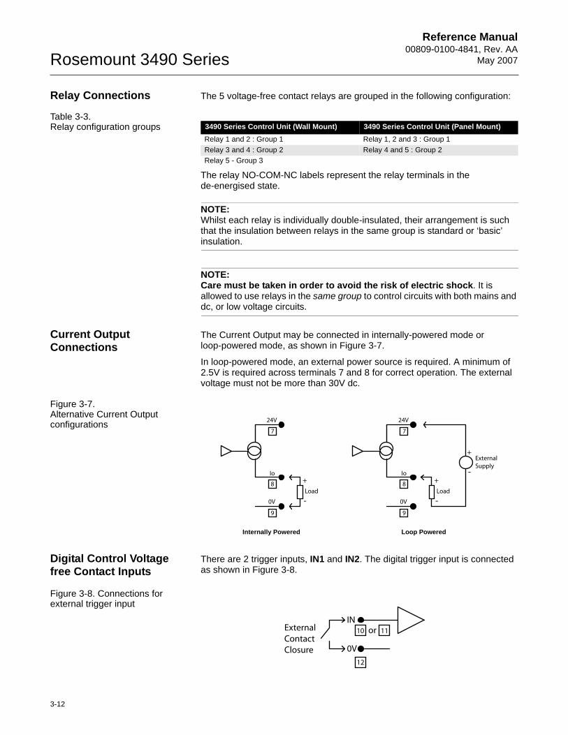
Relay Connections The 5 voltage-free contact relays are grouped in the following configuration:
Table 3-3. Relay configuration groups
The relay NO-COM-NC labels represent the relay terminals in the de-energised state.
NOTE:Whilst each relay is individually double-insulated, their arrangement is such that the insulation between relays in the same group is standard or ‘basic’ insulation.
NOTE:Care must be taken in order to avoid the risk of electric shock. It is allowed to use relays in the same group to control circuits with both mains and dc, or low voltage circuits.
Current Output Connections
The Current Output may be connected in internally-powered mode or loop-powered mode, as shown in Figure 3-7.
In loop-powered mode, an external power source is required. A minimum of 2.5V is required across terminals 7 and 8 for correct operation. The external voltage must not be more than 30V dc.
Figure 3-7. Alternative Current Output configurations
Digital Control Voltage free Contact Inputs
There are 2 trigger inputs, IN1 and IN2. The digital trigger input is connected as shown in Figure 3-8.
Figure 3-8. Connections for external trigger input
3490 Series Control Unit (Wall Mount) 3490 Series Control Unit (Panel Mount)Relay 1 and 2 : Group 1 Relay 1, 2 and 3 : Group 1Relay 3 and 4 : Group 2 Relay 4 and 5 : Group 2Relay 5 - Group 3
7
8
9
0V
Io
24V
Load
+
-
7
8
9
0V
Io
24V
Load
External Supply
+
+
-
-
Internally Powered Loop Powered
INExternalContactClosure 0V
or10 11
12
Reference Manual 00809-0100-4841, Rev. AA May 2007
3-13
Rosemount 3490 Series
RS232 Connections The RS232 connections, terminals 4-6, may be used for exchanging data with a PC or a handheld device.
Model 3493 is supplied with a data-download socket. Connect theflying leads from the socket provided as follows:• 4 - white (RX)• 5 - Red (TX)• 6 - Black (0V)

Reference Manual00809-0100-4841, Rev. AA
May 2007Rosemount 3490 Series
3-14
Reference Manual 00809-0100-4841, Rev. AA May 2007
4-1
Rosemount 3490 Series
Section 4 Getting started
Safety messages . . . . . . . . . . . . . . . . . . . . . . . . . . . . . . . . . page 4-1Switching on . . . . . . . . . . . . . . . . . . . . . . . . . . . . . . . . . . . . page 4-2The Hierarchical menu system . . . . . . . . . . . . . . . . . . . . . page 4-4Programming . . . . . . . . . . . . . . . . . . . . . . . . . . . . . . . . . . . page 4-8
SAFETY MESSAGES Procedures and instructions in this section may require special precautions to ensure the safety of the personnel performing the operations. Information that raises potential safety issues is indicated by a warning symbol ( ). Refer to the safety messages listed at the beginning of each section before performing an operation preceded by this symbol.
Explosions could result in death or serious injury:Verify that the operating environment of the 3490 Series Control Unit is consistent with the appropriate hazardous locations certifications.
Failure to follow safe installation and servicing guidelines could result in death or serious injury:Make sure only qualified personnel perform the installation.
Use the equipment only as specified in this manual. Failure to do so may impair the protection provided by the equipment.
Do not perform any service other than those contained in this manual unless you are qualified.
Reference Manual00809-0100-4841, Rev. AA
May 2007Rosemount 3490 Series
4-2
SWITCHING ON
Switching on the 3491/3493
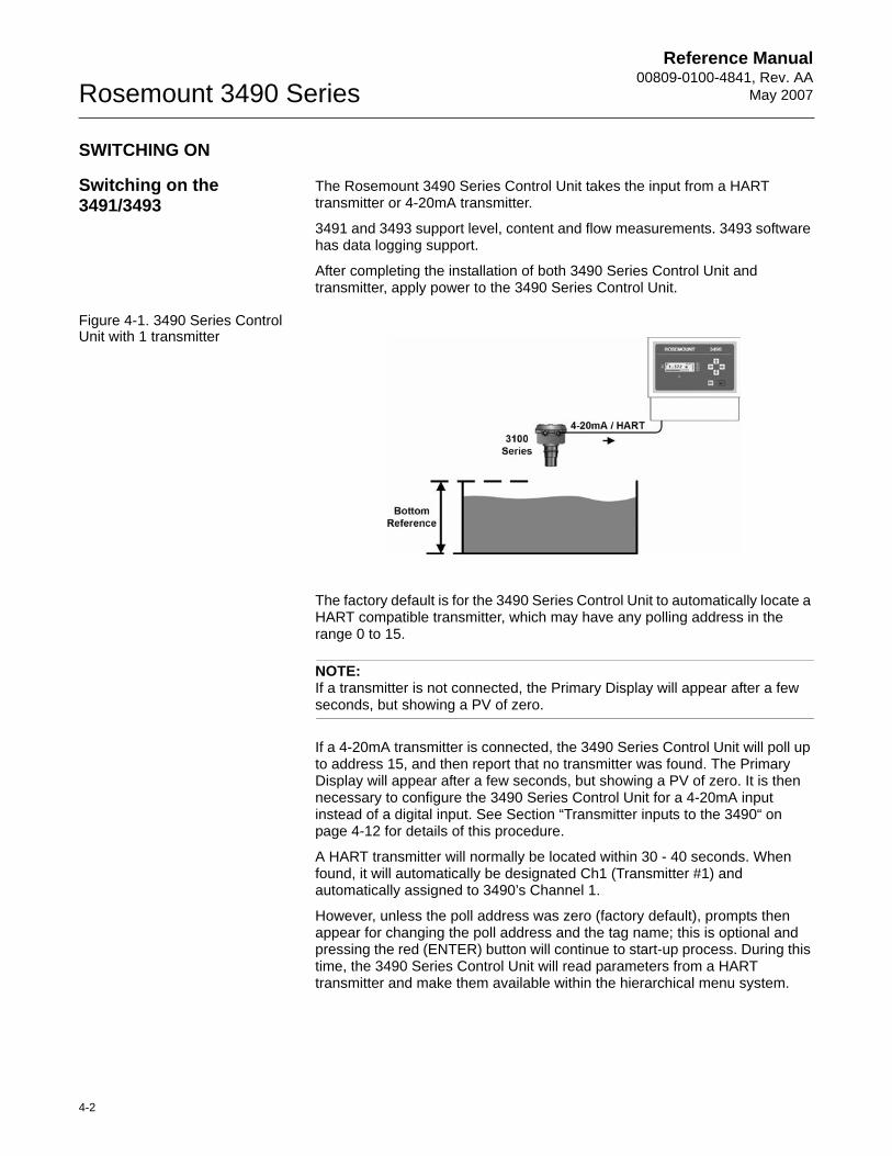
The Rosemount 3490 Series Control Unit takes the input from a HART transmitter or 4-20mA transmitter.
3491 and 3493 support level, content and flow measurements. 3493 software has data logging support.
After completing the installation of both 3490 Series Control Unit and transmitter, apply power to the 3490 Series Control Unit.
Figure 4-1. 3490 Series Control Unit with 1 transmitter
The factory default is for the 3490 Series Control Unit to automatically locate a HART compatible transmitter, which may have any polling address in the range 0 to 15.
NOTE:If a transmitter is not connected, the Primary Display will appear after a few seconds, but showing a PV of zero.
If a 4-20mA transmitter is connected, the 3490 Series Control Unit will poll up to address 15, and then report that no transmitter was found. The Primary Display will appear after a few seconds, but showing a PV of zero. It is then necessary to configure the 3490 Series Control Unit for a 4-20mA input instead of a digital input. See Section “Transmitter inputs to the 3490“ on page 4-12 for details of this procedure.
A HART transmitter will normally be located within 30 - 40 seconds. When found, it will automatically be designated Ch1 (Transmitter #1) and automatically assigned to 3490’s Channel 1.
However, unless the poll address was zero (factory default), prompts then appear for changing the poll address and the tag name; this is optional and pressing the red (ENTER) button will continue to start-up process. During this time, the 3490 Series Control Unit will read parameters from a HART transmitter and make them available within the hierarchical menu system.
Reference Manual 00809-0100-4841, Rev. AA May 2007
4-3
Rosemount 3490 Series
NOTE: If being used for the first time with a Rosemount 3100 Series transmitter, there will be a prompt for the Bottom Reference of the transmitter. This value will then be used to automatically set-up the transmitter 4-20mA output span over this range.If you do not want to commission the system now, simply switch off the power and the same prompt will re-appear when switching on the next time.If you are commissioning the system now, edit the Bottom Reference with the arrow buttons and then press the red (ENTER) button to confirm the programmed value. The Bottom Reference can be changed at a later stage, but it is better to get it correct now. If you press the ESC button, the start-up process will continue and the Bottom Reference prompt will re-appear when switching on the next time.
After the start-up process is complete, the Primary Display appears showing a measurement e.g. depth of the liquid in the tank. The value on the Primary Display is the 3490’s PV (Primary Variable).
Whenever the 3490 Series Control Unit is switched off and then on, it will re-establish digital communications with the HART transmitter and then the Primary Display will appear.
Continue with a tour of the hierarchical menu system on page 4-4, or turn to the Section “Programming“ on page 4-8.
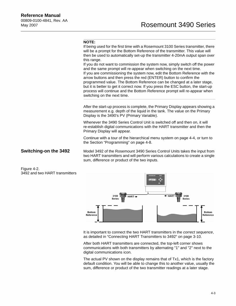
Switching-on the 3492 Model 3492 of the Rosemount 3490 Series Control Units takes the input from two HART transmitters and will perform various calculations to create a single sum, difference or product of the two inputs.
Figure 4-2. 3492 and two HART transmitters
It is important to connect the two HART transmitters in the correct sequence, as detailed in “Connecting HART Transmitters to 3492“ on page 3-10.
After both HART transmitters are connected, the top-left corner shows communications with both transmitters by alternating "1" and "2" next to the digital communications icon.
The actual PV shown on the display remains that of Tx1, which is the factory default condition. You will be able to change this to another value, usually the sum, difference or product of the two transmitter readings at a later stage.
Reference Manual00809-0100-4841, Rev. AA
May 2007Rosemount 3490 Series
4-4
THE HIERARCHICAL MENU SYSTEM
How to navigate the menu system
If you wish to have a quick tour of the menu system, follow instructions in this section, otherwise feel free to explore on your own. Should you get lost, use the ESC button repeatedly until the primary display re-appears.
Tour of menu system:
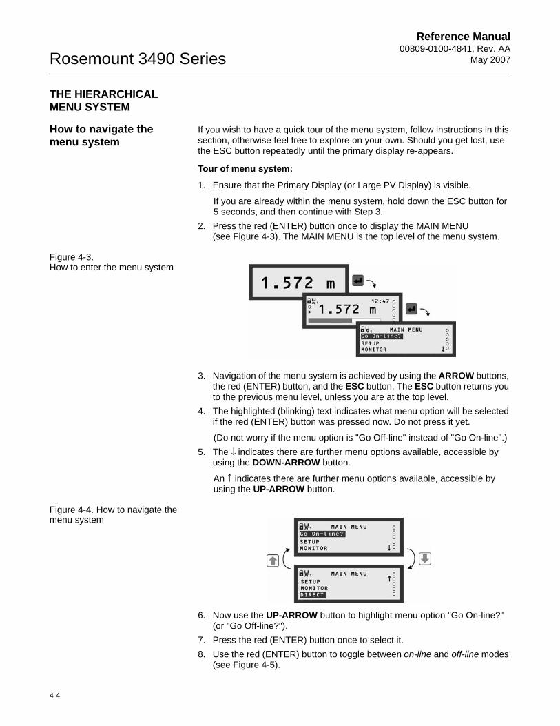
1. Ensure that the Primary Display (or Large PV Display) is visible.
If you are already within the menu system, hold down the ESC button for5 seconds, and then continue with Step 3.
2. Press the red (ENTER) button once to display the MAIN MENU (see Figure 4-3). The MAIN MENU is the top level of the menu system.
Figure 4-3. How to enter the menu system
3. Navigation of the menu system is achieved by using the ARROW buttons, the red (ENTER) button, and the ESC button. The ESC button returns you to the previous menu level, unless you are at the top level.
4. The highlighted (blinking) text indicates what menu option will be selected if the red (ENTER) button was pressed now. Do not press it yet.
(Do not worry if the menu option is "Go Off-line" instead of "Go On-line".)5. The ↓ indicates there are further menu options available, accessible by
using the DOWN-ARROW button.
An ↑ indicates there are further menu options available, accessible by using the UP-ARROW button.
Figure 4-4. How to navigate the menu system
6. Now use the UP-ARROW button to highlight menu option "Go On-line?" (or "Go Off-line?").
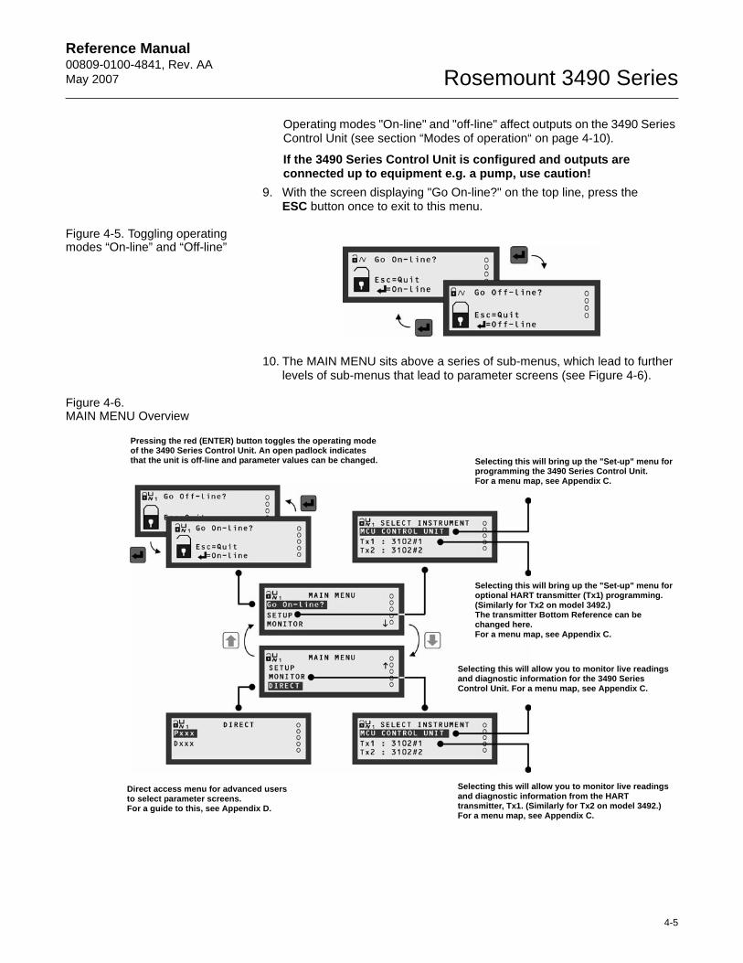
7. Press the red (ENTER) button once to select it.8. Use the red (ENTER) button to toggle between on-line and off-line modes
(see Figure 4-5).
Reference Manual 00809-0100-4841, Rev. AA May 2007
4-5
Rosemount 3490 Series
Operating modes "On-line" and "off-line" affect outputs on the 3490 Series Control Unit (see section “Modes of operation“ on page 4-10).
If the 3490 Series Control Unit is configured and outputs are connected up to equipment e.g. a pump, use caution!
9. With the screen displaying "Go On-line?" on the top line, press theESC button once to exit to this menu.
Figure 4-5. Toggling operating modes “On-line” and “Off-line”
10. The MAIN MENU sits above a series of sub-menus, which lead to further levels of sub-menus that lead to parameter screens (see Figure 4-6).
Figure 4-6. MAIN MENU Overview
Pressing the red (ENTER) button toggles the operating mode of the 3490 Series Control Unit. An open padlock indicates that the unit is off-line and parameter values can be changed. Selecting this will bring up the "Set-up" menu for
programming the 3490 Series Control Unit. For a menu map, see Appendix C.
Selecting this will bring up the "Set-up" menu for optional HART transmitter (Tx1) programming. (Similarly for Tx2 on model 3492.)The transmitter Bottom Reference can be changed here. For a menu map, see Appendix C.
Selecting this will allow you to monitor live readings and diagnostic information for the 3490 Series Control Unit. For a menu map, see Appendix C.
Selecting this will allow you to monitor live readings and diagnostic information from the HART transmitter, Tx1. (Similarly for Tx2 on model 3492.)For a menu map, see Appendix C.
Direct access menu for advanced users to select parameter screens.For a guide to this, see Appendix D.
Reference Manual00809-0100-4841, Rev. AA
May 2007Rosemount 3490 Series
4-6
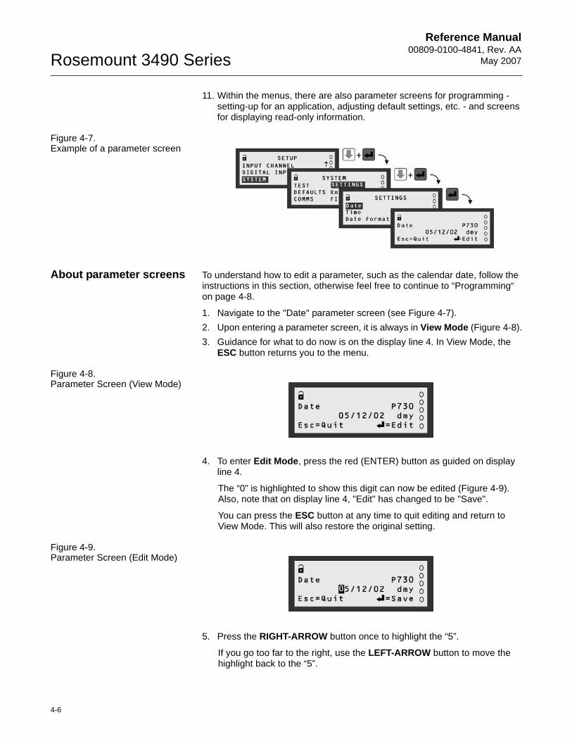
11. Within the menus, there are also parameter screens for programming - setting-up for an application, adjusting default settings, etc. - and screens for displaying read-only information.
Figure 4-7. Example of a parameter screen
About parameter screens To understand how to edit a parameter, such as the calendar date, follow the instructions in this section, otherwise feel free to continue to “Programming“ on page 4-8.
1. Navigate to the "Date" parameter screen (see Figure 4-7).2. Upon entering a parameter screen, it is always in View Mode (Figure 4-8).3. Guidance for what to do now is on the display line 4. In View Mode, the
ESC button returns you to the menu.
Figure 4-8. Parameter Screen (View Mode)
4. To enter Edit Mode, press the red (ENTER) button as guided on display line 4.
The “0” is highlighted to show this digit can now be edited (Figure 4-9). Also, note that on display line 4, "Edit" has changed to be "Save".
You can press the ESC button at any time to quit editing and return to View Mode. This will also restore the original setting.
Figure 4-9. Parameter Screen (Edit Mode)
5. Press the RIGHT-ARROW button once to highlight the “5”.
If you go too far to the right, use the LEFT-ARROW button to move the highlight back to the “5”.
Reference Manual 00809-0100-4841, Rev. AA May 2007
4-7
Rosemount 3490 Series
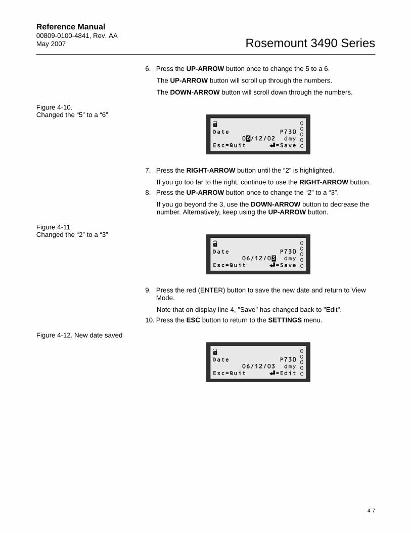
6. Press the UP-ARROW button once to change the 5 to a 6.
The UP-ARROW button will scroll up through the numbers.
The DOWN-ARROW button will scroll down through the numbers.
Figure 4-10. Changed the “5” to a “6”
7. Press the RIGHT-ARROW button until the “2” is highlighted.
If you go too far to the right, continue to use the RIGHT-ARROW button.8. Press the UP-ARROW button once to change the “2” to a “3”.
If you go beyond the 3, use the DOWN-ARROW button to decrease the number. Alternatively, keep using the UP-ARROW button.
Figure 4-11. Changed the “2” to a “3”
9. Press the red (ENTER) button to save the new date and return to View Mode.
Note that on display line 4, "Save" has changed back to "Edit".10. Press the ESC button to return to the SETTINGS menu.
Figure 4-12. New date saved
Reference Manual00809-0100-4841, Rev. AA
May 2007Rosemount 3490 Series
4-8
PROGRAMMING
Before you begin Before embarking on programming (configuring) the 3490 Series Control Unit, it is recommended that you have a working knowledge of important features and programming philosophies.
All setting up is achieved from the front panel of the 3490 Series Control Unit; this includes optional adjustments to the set-up of a HART transmitter.
Parameters
The 3490 Series Control Unit has menu-based parameters for programming - setting up for an application, adjusting default settings, etc. - and for viewing information.
Parameters are populated throughout the menu system. They are grouped in sub-menus, which are organised by association with a specific function or application. Each parameter has a unique 3-digit identification number, prefixed by a 'P' - if programmable - or a 'D' - if for display purposes only. Full menu maps are provided in Appendix C.
With some experience, it becomes easy to locate parameters. Alternatively, parameters can be accessed directly by knowing their unique 3-digit identification number. (See Appendix D for details.)
To make programming of functions and applications easier, various Wizards are provided - See “Wizards“ on page 4-9.
Menu Navigation
In this chapter, a simple notation has been used to guide you to a particular menu screen or parameter screen. This avoids the need for detailed navigation instructions.
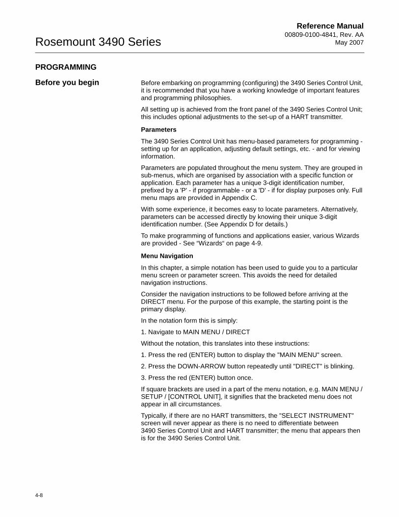
Consider the navigation instructions to be followed before arriving at the DIRECT menu. For the purpose of this example, the starting point is the primary display.
In the notation form this is simply:
1. Navigate to MAIN MENU / DIRECT
Without the notation, this translates into these instructions:
1. Press the red (ENTER) button to display the "MAIN MENU" screen.
2. Press the DOWN-ARROW button repeatedly until "DIRECT" is blinking.
3. Press the red (ENTER) button once.
If square brackets are used in a part of the menu notation, e.g. MAIN MENU / SETUP / [CONTROL UNIT], it signifies that the bracketed menu does not appear in all circumstances.
Typically, if there are no HART transmitters, the "SELECT INSTRUMENT" screen will never appear as there is no need to differentiate between3490 Series Control Unit and HART transmitter; the menu that appears then is for the 3490 Series Control Unit.
Reference Manual 00809-0100-4841, Rev. AA May 2007
4-9
Rosemount 3490 Series
Figure 4-13. Navigating to the DIRECT menu
Wizards
Programming is best achieved through easy-to-follow Wizards. They are simply a sequence of on-screen prompts, allowing you to easily set-up an individual function or a large application without fuss.
There is a collection of Wizards for most functions and applications. They are selected and started through the menu system. Look out for how to use these Wizards in later sections.
Wizard hints:• Display line 4 normally instructs what will occur when pressing the ESC
button and red (ENTER) button.• Arrow buttons scroll through multiple-choice options and edit values.• The red (ENTER) button confirms an edited option/value and then
displays the next prompt.
Approach to setting-up
To make setting-up straightforward, proceed in a structured manner:
First Step:
Put the 3490 Series Control Unit off-line (see Modes of operation below). The factory default is for it to be on-line.
Comfort settings:
This includes how to switch off the keyboard sound, setting the date/time, and changing language - see Section “Comfort (system) settings“ on page 4-11.
Inputs:
This includes setting-up the Input Channels to obtain PV (Primary Variable) values from a transmitter. Also, includes how to allocate actions to digital inputs (IN1 and IN2) - see Sections “Transmitter inputs to the 3490“ on page 4-12 and “Digital Inputs IN1 and IN2“ on page 4-33.
Application:
This includes further processing of PV values to get content (volume) and flow rate values, which can be shown on the Primary Display - see Section “Profile Calculations for Contents and Flow Applications“ on page 4-23.
In addition, a totaliser function can be set-up.
Reference Manual00809-0100-4841, Rev. AA
May 2007Rosemount 3490 Series
4-10
Outputs:
This includes setting-up:• 4-20mA Current Output (see Section “Current Output“ on page 4-38).• Relays (see “Relays“ on page 4-39).
Other features:
This includes configuring Data Logging, Alarm handling, the Primary Display, Serial Communications and Pin Security.
Final Step:
Put the 3490 Series Control Unit on-line (see “Modes of operation”, below). For checks (e.g. Auto-Cycle), diagnostics and faultfinding, seeSection 5: Service and Health Checks.
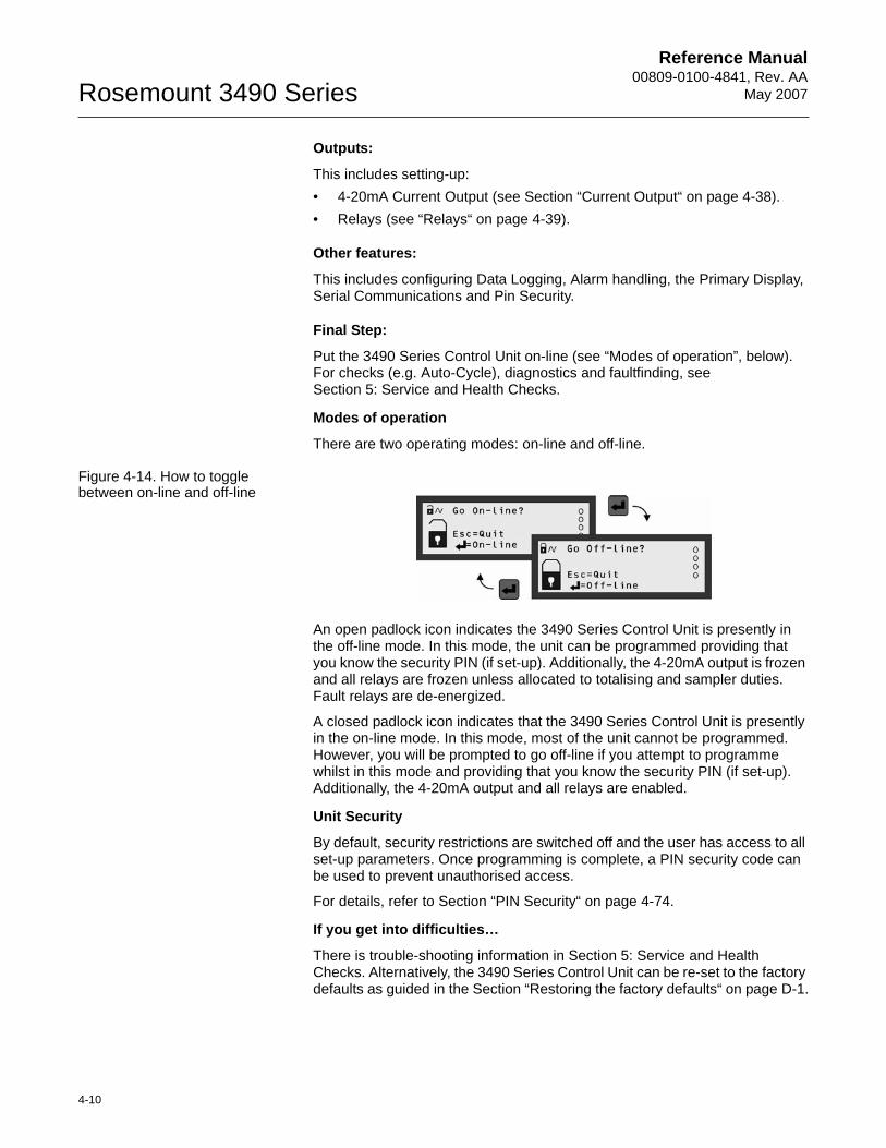
Modes of operation
There are two operating modes: on-line and off-line.
Figure 4-14. How to toggle between on-line and off-line
An open padlock icon indicates the 3490 Series Control Unit is presently in the off-line mode. In this mode, the unit can be programmed providing that you know the security PIN (if set-up). Additionally, the 4-20mA output is frozen and all relays are frozen unless allocated to totalising and sampler duties. Fault relays are de-energized.
A closed padlock icon indicates that the 3490 Series Control Unit is presently in the on-line mode. In this mode, most of the unit cannot be programmed. However, you will be prompted to go off-line if you attempt to programme whilst in this mode and providing that you know the security PIN (if set-up). Additionally, the 4-20mA output and all relays are enabled.
Unit Security
By default, security restrictions are switched off and the user has access to all set-up parameters. Once programming is complete, a PIN security code can be used to prevent unauthorised access.
For details, refer to Section “PIN Security“ on page 4-74.
If you get into difficulties…
There is trouble-shooting information in Section 5: Service and Health Checks. Alternatively, the 3490 Series Control Unit can be re-set to the factory defaults as guided in the Section “Restoring the factory defaults“ on page D-1.
Reference Manual 00809-0100-4841, Rev. AA May 2007
4-11
Rosemount 3490 Series
Comfort (system) settings
Prior to setting up, it is advisable to check the settings of these parameters and, if necessary, make changes. This includes setting the time and date, switching off the keypad sound and changing language.
Menu: MAIN MENU / SETUP / [CONTROL UNIT /] SYSTEM / SETTINGS
Setting the real-time clock
P730 Date
The date format is determined by P734.
P731 Time
The 24-hour clock format is supported.
P734 Date format (Default setting is "dd/mm/yy")
Choose between "dd/mm/yy", "yy/mm/dd" and "mm/dd/yy".
Keypad Sound
P735 Keypad Sound (Default setting is "On")
If you want the keypad sound switched off, select "Off" from the multiple-choice list.
Language
P737 Language (Default setting is "English")
If you wish to change the language used on-screen, there is a choice of other languages.
Reference Manual00809-0100-4841, Rev. AA
May 2007Rosemount 3490 Series
4-12
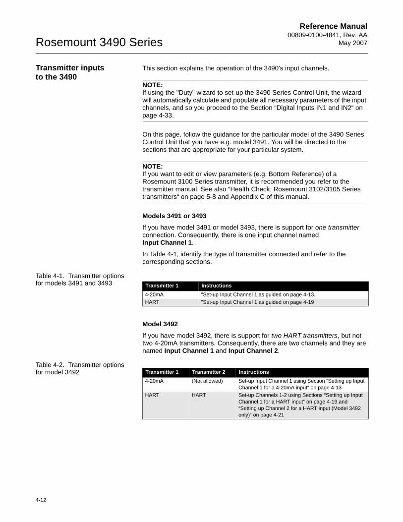
Transmitter inputs to the 3490
This section explains the operation of the 3490’s input channels.
NOTE:If using the "Duty" wizard to set-up the 3490 Series Control Unit, the wizard will automatically calculate and populate all necessary parameters of the input channels, and so you proceed to the Section “Digital Inputs IN1 and IN2“ on page 4-33.
On this page, follow the guidance for the particular model of the 3490 Series Control Unit that you have e.g. model 3491. You will be directed to the sections that are appropriate for your particular system.
NOTE:If you want to edit or view parameters (e.g. Bottom Reference) of a Rosemount 3100 Series transmitter, it is recommended you refer to the transmitter manual. See also “Health Check: Rosemount 3102/3105 Series transmitters“ on page 5-8 and Appendix C of this manual.
Models 3491 or 3493
If you have model 3491 or model 3493, there is support for one transmitter connection. Consequently, there is one input channel namedInput Channel 1.
In Table 4-1, identify the type of transmitter connected and refer to the corresponding sections.
Table 4-1. Transmitter options for models 3491 and 3493
Model 3492
If you have model 3492, there is support for two HART transmitters, but not two 4-20mA transmitters. Consequently, there are two channels and they are named Input Channel 1 and Input Channel 2.
Table 4-2. Transmitter options for model 3492
Transmitter 1 Instructions4-20mA "Set-up Input Channel 1 as guided on page 4-13.HART "Set-up Input Channel 1 as guided on page 4-19
Transmitter 1 Transmitter 2 Instructions4-20mA (Not allowed) Set-up Input Channel 1 using Section “Setting up Input
Channel 1 for a 4-20mA input“ on page 4-13HART HART Set-up Channels 1-2 using Sections “Setting up Input
Channel 1 for a HART input“ on page 4-19.and “Setting up Channel 2 for a HART input (Model 3492 only)“ on page 4-21
Reference Manual 00809-0100-4841, Rev. AA May 2007
4-13
Rosemount 3490 Series
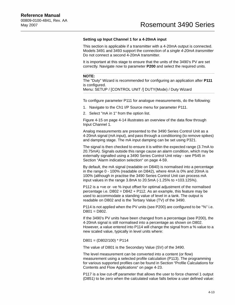
Setting up Input Channel 1 for a 4-20mA input
This section is applicable if a transmitter with a 4-20mA output is connected. Models 3491 and 3493 support the connection of a single 4-20mA transmitter Do not connect a second 4-20mA transmitter.
It is important at this stage to ensure that the units of the 3490’s PV are set correctly. Navigate now to parameter P200 and select the required units.
NOTE: The "Duty" Wizard is recommended for configuring an application after P111 is configured.Menu: SETUP / [CONTROL UNIT /] DUTY(Mode) / Duty Wizard
To configure parameter P111 for analogue measurements, do the following:
1. Navigate to the Ch1 I/P Source menu for parameter P111.2. Select "mA in 1" from the option list.
Figure 4-15 on page 4-14 illustrates an overview of the data flow through Input Channel 1.
Analog measurements are presented to the 3490 Series Control Unit as a 4-20mA signal (mA input), and pass through a conditioning (to remove spikes) and damping stage. The mA input damping can be set using P321.
The signal is then checked to ensure it is within the expected range (3.7mA to 20.75mA). Signals outside this range cause an alarm condition, which may be externally signalled using a 3490 Series Control Unit relay - see P545 in Section “Alarm indication selection“ on page 4-59.
By default, the mA signal (readable on D840) is normalised into a percentage in the range 0 - 100% (readable on D842), where 4mA is 0% and 20mA is 100% (although in practise the 3490 Series Control Unit can process mA input values in the range 3.8mA to 20.5mA (-1.25% to +103.125%).
P112 is a +ve or -ve % input offset for optimal adjustment of the normalised percentage i.e. D802 = D842 + P112. As an example, this feature may be used to accommodate a standing value of level in a tank. The output is readable on D802 and is the Tertiary Value (TV) of the 3490.
P114 is not applied when the PV units (see P200) are configured to be "%" i.e. D801 = D802.
If the 3490’s PV units have been changed from a percentage (see P200), the 4-20mA signal is still normalised into a percentage as shown on D802. However, a value entered into P114 will change the signal from a % value to a new scaled value, typically in level units where:
D801 = (D802/100) * P114
The value of D801 is the Secondary Value (SV) of the 3490.
The level measurement can be converted into a content (or flow) measurement using a selected profile calculation (P113). The programming for various supported profiles can be found in Section “Profile Calculations for Contents and Flow Applications“ on page 4-23.
P117 is a low cut-off parameter that allows the user to force channel 1 output (D851) to be zero when the calculated value falls below a user defined value:
Reference Manual00809-0100-4841, Rev. AA
May 2007Rosemount 3490 Series
4-14
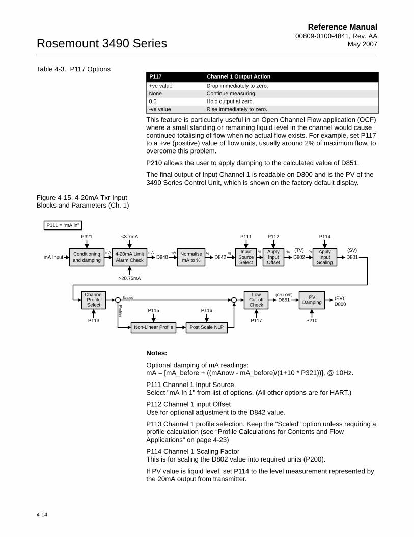
Table 4-3. P117 Options
This feature is particularly useful in an Open Channel Flow application (OCF) where a small standing or remaining liquid level in the channel would cause continued totalising of flow when no actual flow exists. For example, set P117 to a +ve (positive) value of flow units, usually around 2% of maximum flow, to overcome this problem.
P210 allows the user to apply damping to the calculated value of D851.
The final output of Input Channel 1 is readable on D800 and is the PV of the 3490 Series Control Unit, which is shown on the factory default display.
Figure 4-15. 4-20mA Txr Input Blocks and Parameters (Ch. 1)
Notes:
Optional damping of mA readings:mA = [mA_before + ((mAnow - mA_before)/(1+10 * P321))], @ 10Hz.
P111 Channel 1 Input SourceSelect "mA In 1" from list of options. (All other options are for HART.)
P112 Channel 1 input OffsetUse for optional adjustment to the D842 value.
P113 Channel 1 profile selection. Keep the "Scaled" option unless requiring a profile calculation (see “Profile Calculations for Contents and Flow Applications“ on page 4-23)
P114 Channel 1 Scaling FactorThis is for scaling the D802 value into required units (P200).
If PV value is liquid level, set P114 to the level measurement represented by the 20mA output from transmitter.
P117 Channel 1 Output Action+ve value Drop immediately to zero.None Continue measuring.0.0 Hold output at zero.-ve value Rise immediately to zero.
Conditioning and dampingmA Input
P321
Normalise mA to %
InputSourceSelect
P111
D842mA mA % % Apply
InputOffset
P112
ChannelProfile Select
D802(TV)
D840ApplyInput
Scaling
P114
% % %mAD801(SV)
P113
LowCut-off Check
ScaledProfiles
Non-Linear Profile Post Scale NLP
(PV)D800
4-20mA Limit Alarm Check
<3.7mA
>20.75mA
P117
P115 P116
D851(CH1 O/P)
P111 = “mA in”
PVDamping
P210
Reference Manual 00809-0100-4841, Rev. AA May 2007
4-15
Rosemount 3490 Series
P117 Channel 1 Low Cut-offUse for forcing D800 to zero while D851 is less than P117
P20x Displayed measurement unitsP200 for PV (D800), P201 for SV (D801) and P202 for TV (D802)
P210 Optional damping of MCU PV (at 10 Hz)Using D800 = [D800_before + ((D800_now - D800_before)/(1+10 * P210))]
For use of P115 and P116, refer to Section “Profile Calculations for Contents and Flow Applications“ on page 4-23.
D800 is the PV (Process Variable) value of the 3490 Series Control Unit.
D801, D802, D840 and D842 are intermediate results. (They are useful for trouble-shooting - see “Service and Health Checks“ on page 5-1.)
Reference Manual00809-0100-4841, Rev. AA
May 2007Rosemount 3490 Series
4-16
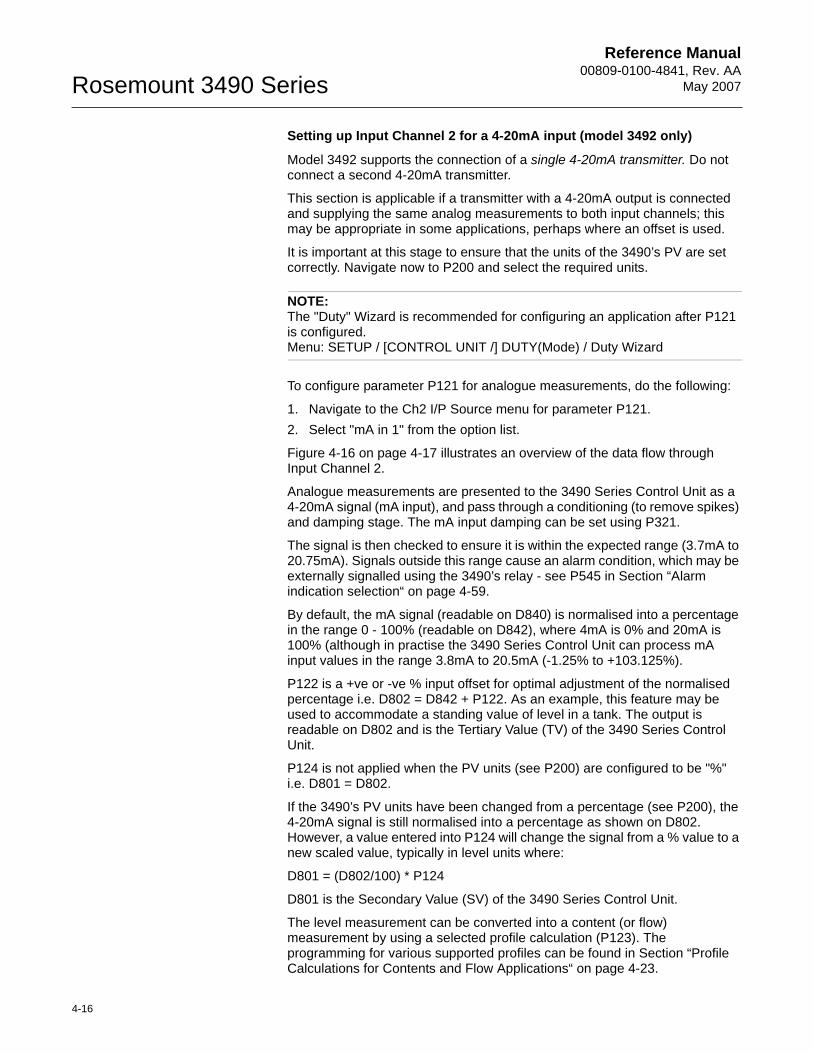
Setting up Input Channel 2 for a 4-20mA input (model 3492 only)
Model 3492 supports the connection of a single 4-20mA transmitter. Do not connect a second 4-20mA transmitter.
This section is applicable if a transmitter with a 4-20mA output is connected and supplying the same analog measurements to both input channels; this may be appropriate in some applications, perhaps where an offset is used.
It is important at this stage to ensure that the units of the 3490’s PV are set correctly. Navigate now to P200 and select the required units.
NOTE:The "Duty" Wizard is recommended for configuring an application after P121 is configured.Menu: SETUP / [CONTROL UNIT /] DUTY(Mode) / Duty Wizard
To configure parameter P121 for analogue measurements, do the following:
1. Navigate to the Ch2 I/P Source menu for parameter P121.2. Select "mA in 1" from the option list.
Figure 4-16 on page 4-17 illustrates an overview of the data flow through Input Channel 2.
Analogue measurements are presented to the 3490 Series Control Unit as a 4-20mA signal (mA input), and pass through a conditioning (to remove spikes) and damping stage. The mA input damping can be set using P321.
The signal is then checked to ensure it is within the expected range (3.7mA to 20.75mA). Signals outside this range cause an alarm condition, which may be externally signalled using the 3490’s relay - see P545 in Section “Alarm indication selection“ on page 4-59.
By default, the mA signal (readable on D840) is normalised into a percentage in the range 0 - 100% (readable on D842), where 4mA is 0% and 20mA is 100% (although in practise the 3490 Series Control Unit can process mA input values in the range 3.8mA to 20.5mA (-1.25% to +103.125%).
P122 is a +ve or -ve % input offset for optimal adjustment of the normalised percentage i.e. D802 = D842 + P122. As an example, this feature may be used to accommodate a standing value of level in a tank. The output is readable on D802 and is the Tertiary Value (TV) of the 3490 Series Control Unit.
P124 is not applied when the PV units (see P200) are configured to be "%" i.e. D801 = D802.
If the 3490’s PV units have been changed from a percentage (see P200), the 4-20mA signal is still normalised into a percentage as shown on D802. However, a value entered into P124 will change the signal from a % value to a new scaled value, typically in level units where:
D801 = (D802/100) * P124
D801 is the Secondary Value (SV) of the 3490 Series Control Unit.
The level measurement can be converted into a content (or flow) measurement by using a selected profile calculation (P123). The programming for various supported profiles can be found in Section “Profile Calculations for Contents and Flow Applications“ on page 4-23.
Reference Manual 00809-0100-4841, Rev. AA May 2007
4-17
Rosemount 3490 Series
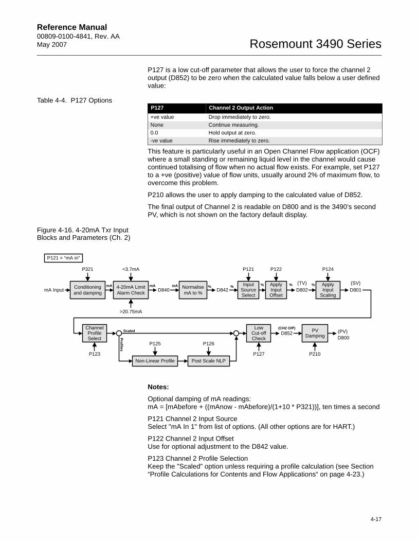
P127 is a low cut-off parameter that allows the user to force the channel 2 output (D852) to be zero when the calculated value falls below a user defined value:
Table 4-4. P127 Options
This feature is particularly useful in an Open Channel Flow application (OCF) where a small standing or remaining liquid level in the channel would cause continued totalising of flow when no actual flow exists. For example, set P127 to a +ve (positive) value of flow units, usually around 2% of maximum flow, to overcome this problem.
P210 allows the user to apply damping to the calculated value of D852.
The final output of Channel 2 is readable on D800 and is the 3490’s second PV, which is not shown on the factory default display.
Figure 4-16. 4-20mA Txr Input Blocks and Parameters (Ch. 2)
Notes:
Optional damping of mA readings:mA = [mAbefore + ((mAnow - mAbefore)/(1+10 * P321))], ten times a second
P121 Channel 2 Input SourceSelect "mA In 1" from list of options. (All other options are for HART.)
P122 Channel 2 Input OffsetUse for optional adjustment to the D842 value.
P123 Channel 2 Profile SelectionKeep the "Scaled" option unless requiring a profile calculation (see Section “Profile Calculations for Contents and Flow Applications“ on page 4-23.)
P127 Channel 2 Output Action+ve value Drop immediately to zero.None Continue measuring.0.0 Hold output at zero.-ve value Rise immediately to zero.
Conditioning and dampingmA Input
P321
Normalise mA to %
InputSourceSelect
P121
D842mA mA % % Apply
InputOffset
P122
ChannelProfile Select
D802(TV)
D840ApplyInput
Scaling
P124
% % %mAD801(SV)
P123
LowCut-off Check
Scaled
Profiles
Non-Linear Profile Post Scale NLP
(PV)D800
4-20mA Limit Alarm Check
<3.7mA
>20.75mA
P127
P125 P126
D852(CH2 O/P)
P121 = “mA in”
PVDamping
P210
Reference Manual00809-0100-4841, Rev. AA
May 2007Rosemount 3490 Series
4-18
P124 Channel 2 Scaling FactorThis is for scaling the D802 value into required units (P200). If PV value is the liquid level, set P124 to the level measurement represented by the 20mA output from transmitter.
P127 Channel 2 Low Cut-offUse for forcing D800 to zero while D851 is less than P127
P20x Displayed Measurement UnitsP200 for PV (D800), P201 for SV (D801) and P202 for TV (D802)
P210 Optional damping of MCU PV whereD800 = [D800before + ((D800now - D800before)/(1+10 * P210))], at 10 Hz.
For an explanation of P125 and P126, see P115 and P116 in “Profile Calculations for Contents and Flow Applications“ on page 4-23.
D800 is the PV (Process Variable) value of the 3490 Series Control Unit
D801, D802, D840 and D842 are intermediate results. (They are useful for trouble-shooting - see “Service and Health Checks“ on page 5-1.)
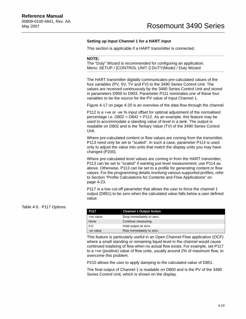
Reference Manual 00809-0100-4841, Rev. AA May 2007
4-19
Rosemount 3490 Series
Setting up Input Channel 1 for a HART input
This section is applicable if a HART transmitter is connected.
NOTE:The "Duty" Wizard is recommended for configuring an application.Menu: SETUP / [CONTROL UNIT /] DUTY(Mode) / Duty Wizard
The HART transmitter digitally communicates pre-calculated values of the four variables (PV, SV, TV and FV) to the 3490 Series Control Unit. The values are received continuously by the 3490 Series Control Unit and stored in parameters D900 to D903. Parameter P111 nominates one of these four variables to be the source for the PV value of Input Channel 1.
Figure 4-17 on page 4-20 is an overview of the data flow through the channel.
P112 is a +ve or -ve % input offset for optimal adjustment of the normalised percentage i.e. D802 = D842 + P112. As an example, this feature may be used to accommodate a standing value of level in a tank. The output is readable on D802 and is the Tertiary Value (TV) of the 3490 Series Control Unit.
Where pre-calculated content or flow values are coming from the transmitter, P113 need only be set to "scaled". In such a case, parameter P114 is used only to adjust the value into units that match the display units you may have changed (P200).
Where pre-calculated level values are coming in from the HART transmitter, P113 can be set to "scaled" if wanting just level measurement; use P114 as above. Otherwise, P113 can be set to a profile for generating content or flow values. For the programming details involving various supported profiles, refer to Section “Profile Calculations for Contents and Flow Applications“ on page 4-23.
P117 is a low cut-off parameter that allows the user to force the channel 1 output (D851) to be zero when the calculated value falls below a user defined value:
Table 4-5. P117 Options
This feature is particularly useful in an Open Channel Flow application (OCF) where a small standing or remaining liquid level in the channel would cause continued totalising of flow when no actual flow exists. For example, set P117 to a +ve (positive) value of flow units, usually around 2% of maximum flow, to overcome this problem.
P210 allows the user to apply damping to the calculated value of D851.
The final output of Channel 1 is readable on D800 and is the PV of the 3490 Series Control Unit, which is shown on the display.
P117 Channel 1 Output Action+ve value Drop immediately to zero.None Continue measuring.0.0 Hold output at zero.-ve value Rise immediately to zero.
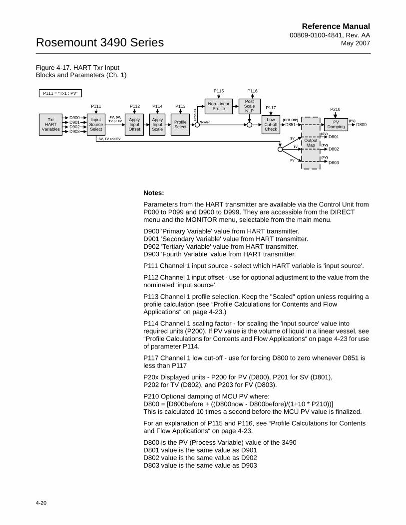
Reference Manual00809-0100-4841, Rev. AA
May 2007Rosemount 3490 Series
4-20
Figure 4-17. HART Txr Input Blocks and Parameters (Ch. 1)
Notes:
Parameters from the HART transmitter are available via the Control Unit from P000 to P099 and D900 to D999. They are accessible from the DIRECT menu and the MONITOR menu, selectable from the main menu.
D900 'Primary Variable' value from HART transmitter.D901 'Secondary Variable' value from HART transmitter.D902 'Tertiary Variable' value from HART transmitter.D903 'Fourth Variable' value from HART transmitter.
P111 Channel 1 input source - select which HART variable is 'input source'.
P112 Channel 1 input offset - use for optional adjustment to the value from the nominated 'input source'.
P113 Channel 1 profile selection. Keep the "Scaled" option unless requiring a profile calculation (see “Profile Calculations for Contents and Flow Applications“ on page 4-23.)
P114 Channel 1 scaling factor - for scaling the 'input source' value into required units (P200). If PV value is the volume of liquid in a linear vessel, see “Profile Calculations for Contents and Flow Applications“ on page 4-23 for use of parameter P114.
P117 Channel 1 low cut-off - use for forcing D800 to zero whenever D851 is less than P117
P20x Displayed units - P200 for PV (D800), P201 for SV (D801), P202 for TV (D802), and P203 for FV (D803).
P210 Optional damping of MCU PV where:D800 = [D800before + ((D800now - D800before)/(1+10 * P210))]This is calculated 10 times a second before the MCU PV value is finalized.
For an explanation of P115 and P116, see “Profile Calculations for Contents and Flow Applications“ on page 4-23.
D800 is the PV (Process Variable) value of the 3490D801 value is the same value as D901D802 value is the same value as D902D803 value is the same value as D903
InputSourceSelect
P111
D900TxrHART
VariablesD901D902D903
PV, SV, TV or FV
P112
ApplyInputOffset
P114
ApplyInputScale
(SV)D801
(TV)D802
(FV)
D803
SV, TV and FV
LowCut-off Check
D800Profile Select
P113
Scaled
Prof
iles
Non-Linear Profile
PostScaleNLP
(PV)
OutputMap
P117
SV
P115 P116
TV
FV
D851(CH1 O/P)
P111 = “Tx1 : PV”
PVDamping
P210
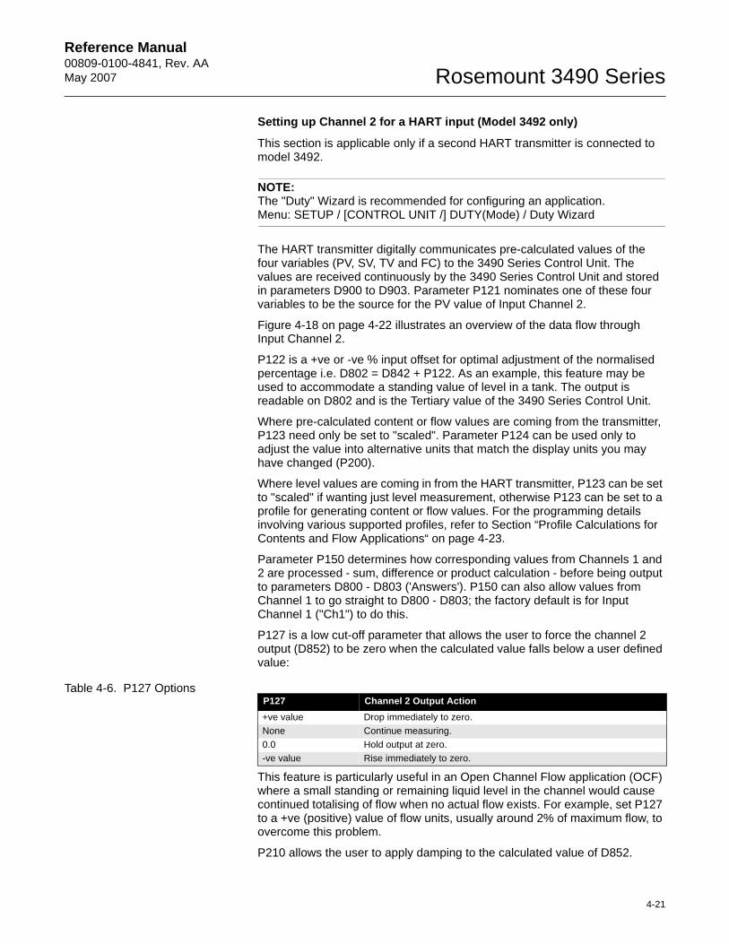
Reference Manual 00809-0100-4841, Rev. AA May 2007
4-21
Rosemount 3490 Series
Setting up Channel 2 for a HART input (Model 3492 only)
This section is applicable only if a second HART transmitter is connected to model 3492.
NOTE:The "Duty" Wizard is recommended for configuring an application.Menu: SETUP / [CONTROL UNIT /] DUTY(Mode) / Duty Wizard
The HART transmitter digitally communicates pre-calculated values of the four variables (PV, SV, TV and FC) to the 3490 Series Control Unit. The values are received continuously by the 3490 Series Control Unit and stored in parameters D900 to D903. Parameter P121 nominates one of these four variables to be the source for the PV value of Input Channel 2.
Figure 4-18 on page 4-22 illustrates an overview of the data flow through Input Channel 2.
P122 is a +ve or -ve % input offset for optimal adjustment of the normalised percentage i.e. D802 = D842 + P122. As an example, this feature may be used to accommodate a standing value of level in a tank. The output is readable on D802 and is the Tertiary value of the 3490 Series Control Unit.
Where pre-calculated content or flow values are coming from the transmitter, P123 need only be set to "scaled". Parameter P124 can be used only to adjust the value into alternative units that match the display units you may have changed (P200).
Where level values are coming in from the HART transmitter, P123 can be set to "scaled" if wanting just level measurement, otherwise P123 can be set to a profile for generating content or flow values. For the programming details involving various supported profiles, refer to Section “Profile Calculations for Contents and Flow Applications“ on page 4-23.
Parameter P150 determines how corresponding values from Channels 1 and 2 are processed - sum, difference or product calculation - before being output to parameters D800 - D803 ('Answers'). P150 can also allow values from Channel 1 to go straight to D800 - D803; the factory default is for Input Channel 1 ("Ch1") to do this.
P127 is a low cut-off parameter that allows the user to force the channel 2 output (D852) to be zero when the calculated value falls below a user defined value:
Table 4-6. P127 Options
This feature is particularly useful in an Open Channel Flow application (OCF) where a small standing or remaining liquid level in the channel would cause continued totalising of flow when no actual flow exists. For example, set P127 to a +ve (positive) value of flow units, usually around 2% of maximum flow, to overcome this problem.
P210 allows the user to apply damping to the calculated value of D852.
P127 Channel 2 Output Action+ve value Drop immediately to zero.None Continue measuring.0.0 Hold output at zero.-ve value Rise immediately to zero.
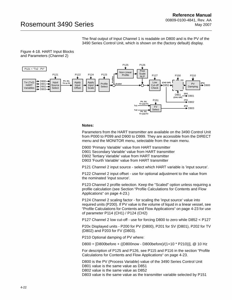
Reference Manual00809-0100-4841, Rev. AA
May 2007Rosemount 3490 Series
4-22
The final output of Input Channel 1 is readable on D800 and is the PV of the 3490 Series Control Unit, which is shown on the (factory default) display.
Figure 4-18. HART Input Blocks and Parameters (Channel 2)
Notes:
Parameters from the HART transmitter are available on the 3490 Control Unit from P000 to P099 and D900 to D999. They are accessible from the DIRECT menu and the MONITOR menu, selectable from the main menu.
D900 'Primary Variable' value from HART transmitterD901 Secondary Variable' value from HART transmitterD902 Tertiary Variable' value from HART transmitterD903 'Fourth Variable' value from HART transmitter
P121 Channel 2 input source - select which HART variable is 'input source'.
P122 Channel 2 input offset - use for optional adjustment to the value from the nominated 'input source'.
P123 Channel 2 profile selection. Keep the "Scaled" option unless requiring a profile calculation (see Section “Profile Calculations for Contents and Flow Applications“ on page 4-23.)
P124 Channel 2 scaling factor - for scaling the 'input source' value into required units (P200). If PV value is the volume of liquid in a linear vessel, see “Profile Calculations for Contents and Flow Applications“ on page 4-23 for use of parameter P114 (CH1) / P124 (CH2)
P127 Channel 2 low cut-off - use for forcing D800 to zero while D852 < P127
P20x Displayed units - P200 for PV (D800), P201 for SV (D801), P202 for TV (D802) and P203 for FV (D803).
P210 Optional damping of PV where:
D800 = [D800before + ((D800now - D800before)/(1+10 * P210))], @ 10 Hz
For description of P125 and P126, see P115 and P116 in the section “Profile Calculations for Contents and Flow Applications“ on page 4-23.
D800 is the PV (Process Variable) value of the 3490 Series Control UnitD801 value is the same value as D851D802 value is the same value as D852D803 value is the same value as the transmitter variable selected by P151
InputSourceSelect
P121
D900Txr (Tx2)HART
VariablesD901D902D903
PV, SV, TV or FV
P122
ApplyInputOffset
P124
ApplyInputScale
(SV)D801
(TV)D802
(FV)D803
LowCut-off Check
D800Profile Select
P123
Scaled
Prof
iles
Non-Linear Profile
Post Scale NLP
(PV)
P127 P150
D851(CH1 O/P)
P125 P126
D852(CH2 O/P)
FV Select
Tx1
Tx2
PV, SV,TV and FV
PV, SV,TV and FV
P151
PVDamping
P210
P121 = “Tx2 : PV”
Reference Manual 00809-0100-4841, Rev. AA May 2007
4-23
Rosemount 3490 Series
Profile Calculations for Contents and Flow Applications
The 3490 Series Control Unit can use level measurements to calculate the content in linear or non-linear shaped closed-vessels. In addition, flow in open-channels can be calculated and totalled. The 3490 Series Control Unit has a library of pre-programmed profiles and supports a user-defined profile.
The data flow diagrams in “Transmitter inputs to the 3490“ on page 4-12 show how the various parameters are used to calculate the final 3490’s PV.
NOTE:You are strongly recommended to use the "Duty" Wizard for setting up content and flow applications, as this will automatically calculate and populate the relevant parameters. The Wizard will guide you through all the setting up and populate parameters with values and settings.Menu: SETUP / [CONTROL UNIT /] DUTY(Mode) / Duty Wizard
Linear Profile (Content from Level)
Parameter P113 must be set to "Scaled", which establishes that the relationship between the liquid level and the content (PV value) derived from that level is linear.
For the linear profile, e.g. vertical cylinder or rectangular vessel, parameter P114 either defines the maximum content (if 4-20mA transmitter used) or area of the vessel's cross-section (if HART transmitter used). The PV value (D800) for the content is then calculated as the live level measurement multiplied by the value in parameter P114.
Standard 4-20mA input (Figure 4-15 on page 4-14):• P200 (units) must have changed from "%" to the required units of
measurement.• P114 is used to define maximum contents of the linear profile vessel.• The PV value (D800) is calculated using: D800 = P114 x (D802 / 100)• Note that P115 and P116 are bypassed in this scenario.
HART digital input (Figure 4-17 on page 4-20):• P200 (PV units) must be set to the required units of measurement.• P114 is used to define the contents of the linear vessel per unit of level
measurement. If the input from the HART transmitter is in metres, the value of P114 is the contents of the vessel per metre of height. If the input from the HART transmitter is in feet, the value of P114 is the contents of the vessel per foot of height.
• The PV value (D800) is calculated using: D800 = ( P114 x Level measurement).
• Note that P115 and P116 are bypassed in this scenario.
Non-linear Profiles (Content from Level)• Non-linear profiles for content:• Horizontal cylinder with flat ends.• Spherical vessel.• Horizontal cylinder with domed ends.• Special (plotted).
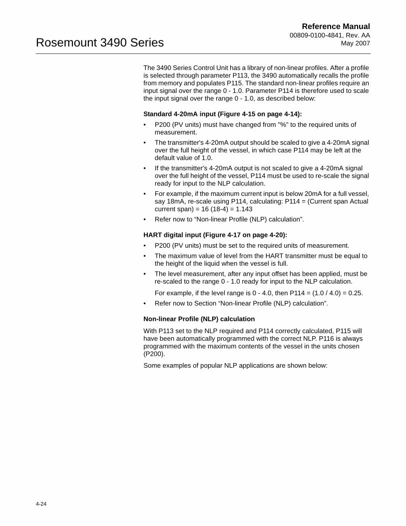
Reference Manual00809-0100-4841, Rev. AA
May 2007Rosemount 3490 Series
4-24
The 3490 Series Control Unit has a library of non-linear profiles. After a profile is selected through parameter P113, the 3490 automatically recalls the profile from memory and populates P115. The standard non-linear profiles require an input signal over the range 0 - 1.0. Parameter P114 is therefore used to scale the input signal over the range 0 - 1.0, as described below:
Standard 4-20mA input (Figure 4-15 on page 4-14):• P200 (PV units) must have changed from "%" to the required units of
measurement.• The transmitter's 4-20mA output should be scaled to give a 4-20mA signal
over the full height of the vessel, in which case P114 may be left at the default value of 1.0.
• If the transmitter's 4-20mA output is not scaled to give a 4-20mA signal over the full height of the vessel, P114 must be used to re-scale the signal ready for input to the NLP calculation.
• For example, if the maximum current input is below 20mA for a full vessel, say 18mA, re-scale using P114, calculating: P114 = (Current span Actual current span) = 16 (18-4) = 1.143
• Refer now to “Non-linear Profile (NLP) calculation”.
HART digital input (Figure 4-17 on page 4-20):• P200 (PV units) must be set to the required units of measurement.• The maximum value of level from the HART transmitter must be equal to
the height of the liquid when the vessel is full.• The level measurement, after any input offset has been applied, must be
re-scaled to the range 0 - 1.0 ready for input to the NLP calculation.
For example, if the level range is 0 - 4.0, then P114 = (1.0 / 4.0) = 0.25.• Refer now to Section “Non-linear Profile (NLP) calculation”.
Non-linear Profile (NLP) calculation
With P113 set to the NLP required and P114 correctly calculated, P115 will have been automatically programmed with the correct NLP. P116 is always programmed with the maximum contents of the vessel in the units chosen (P200).
Some examples of popular NLP applications are shown below:
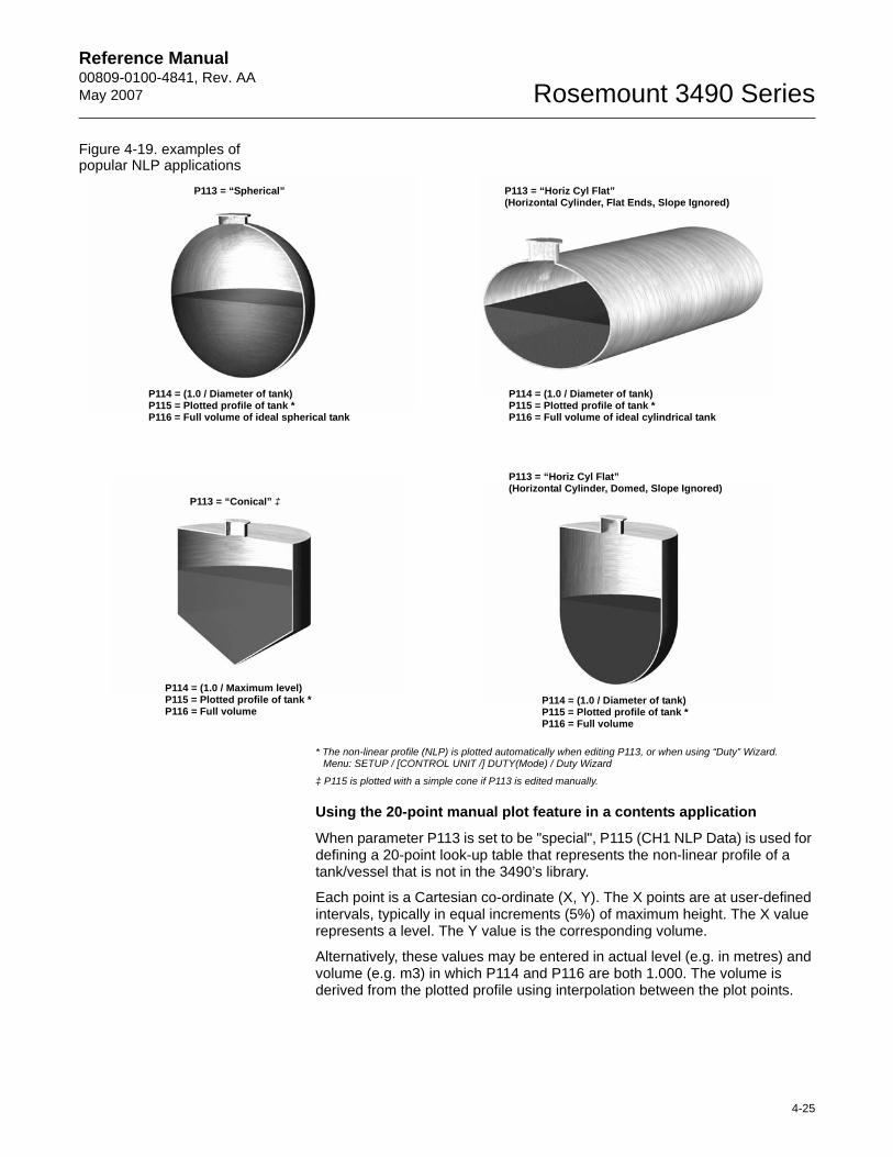
Reference Manual 00809-0100-4841, Rev. AA May 2007
4-25
Rosemount 3490 Series
Figure 4-19. examples of popular NLP applications
* The non-linear profile (NLP) is plotted automatically when editing P113, or when using “Duty” Wizard.Menu: SETUP / [CONTROL UNIT /] DUTY(Mode) / Duty Wizard
‡ P115 is plotted with a simple cone if P113 is edited manually.
Using the 20-point manual plot feature in a contents application
When parameter P113 is set to be "special", P115 (CH1 NLP Data) is used for defining a 20-point look-up table that represents the non-linear profile of a tank/vessel that is not in the 3490’s library.
Each point is a Cartesian co-ordinate (X, Y). The X points are at user-defined intervals, typically in equal increments (5%) of maximum height. The X value represents a level. The Y value is the corresponding volume.
Alternatively, these values may be entered in actual level (e.g. in metres) and volume (e.g. m3) in which P114 and P116 are both 1.000. The volume is derived from the plotted profile using interpolation between the plot points.
P113 = “Spherical”
P114 = (1.0 / Diameter of tank)P115 = Plotted profile of tank *P116 = Full volume of ideal spherical tank
P113 = “Horiz Cyl Flat”(Horizontal Cylinder, Flat Ends, Slope Ignored)
P114 = (1.0 / Diameter of tank)P115 = Plotted profile of tank *P116 = Full volume of ideal cylindrical tank
P113 = “Conical” ‡
P114 = (1.0 / Maximum level)P115 = Plotted profile of tank *P116 = Full volume
P113 = “Horiz Cyl Flat”(Horizontal Cylinder, Domed, Slope Ignored)
P114 = (1.0 / Diameter of tank)P115 = Plotted profile of tank *P116 = Full volume
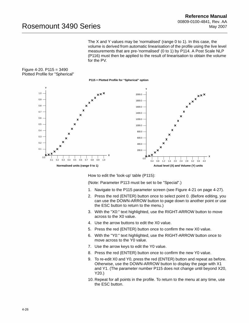
Reference Manual00809-0100-4841, Rev. AA
May 2007Rosemount 3490 Series
4-26
The X and Y values may be 'normalised' (range 0 to 1). In this case, the volume is derived from automatic linearisation of the profile using the live level measurements that are pre-'normalised' (0 to 1) by P114. A Post Scale NLP (P116) must then be applied to the result of linearisation to obtain the volume for the PV.
Figure 4-20. P115 = 3490 Plotted Profile for "Spherical"
How to edit the 'look-up' table (P115):
(Note: Parameter P113 must be set to be "Special".)
1. Navigate to the P115 parameter screen (see Figure 4-21 on page 4-27).2. Press the red (ENTER) button once to select point 0. (Before editing, you
can use the DOWN-ARROW button to page down to another point or use the ESC button to return to the menu.)
3. With the "X0:" text highlighted, use the RIGHT-ARROW button to move across to the X0 value.
4. Use the arrow buttons to edit the X0 value.5. Press the red (ENTER) button once to confirm the new X0 value.6. With the "Y0:" text highlighted, use the RIGHT-ARROW button once to
move across to the Y0 value.7. Use the arrow keys to edit the Y0 value.8. Press the red (ENTER) button once to confirm the new Y0 value.9. To re-edit X0 and Y0, press the red (ENTER) button and repeat as before.
Otherwise, use the DOWN-ARROW button to display the page with X1 and Y1. (The parameter number P115 does not change until beyond X20, Y20.)
10. Repeat for all points in the profile. To return to the menu at any time, use the ESC button.
0.1
0.2
0.3
0.4
0.5
0.6
0.7
0.8
0.9
1.0
0.1 0.2 0.3 0.4 0.5 0.6 0.7 0.8 0.9 1.00.0
Y
X
200.0
400.0
600.0
800.0
1000.0
1200.0
1400.0
1600.0
1800.0
2000.0
0.4 0.8 1.2 1.6 2.0 2.4 2.8 3.2 3.6 4.00.0
Y
X
P115 = Plotted Profile for “Spherical” option
Normalised units (range 0 to 1) Actual level (X) and Volume (Y) units
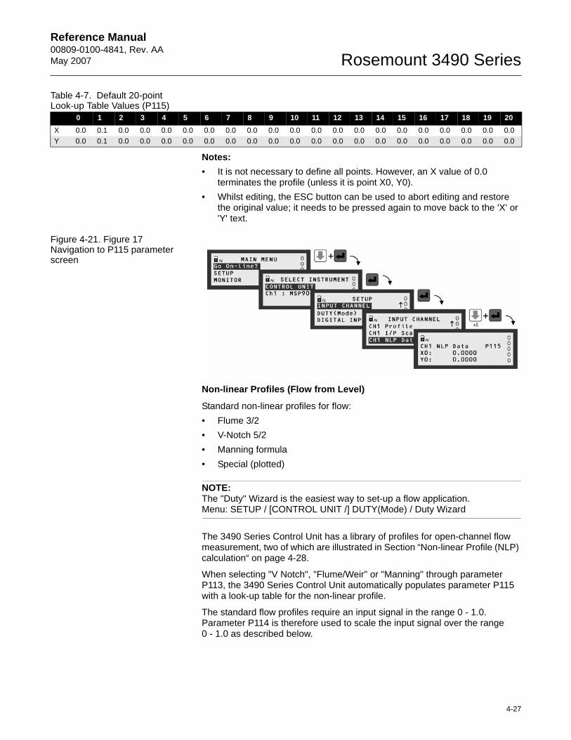
Reference Manual 00809-0100-4841, Rev. AA May 2007
4-27
Rosemount 3490 Series
Table 4-7. Default 20-point Look-up Table Values (P115)
Notes:• It is not necessary to define all points. However, an X value of 0.0
terminates the profile (unless it is point X0, Y0).• Whilst editing, the ESC button can be used to abort editing and restore
the original value; it needs to be pressed again to move back to the 'X' or 'Y' text.
Figure 4-21. Figure 17 Navigation to P115 parameter screen
Non-linear Profiles (Flow from Level)
Standard non-linear profiles for flow:• Flume 3/2• V-Notch 5/2• Manning formula• Special (plotted)
NOTE:The "Duty" Wizard is the easiest way to set-up a flow application. Menu: SETUP / [CONTROL UNIT /] DUTY(Mode) / Duty Wizard
The 3490 Series Control Unit has a library of profiles for open-channel flow measurement, two of which are illustrated in Section “Non-linear Profile (NLP) calculation“ on page 4-28.
When selecting "V Notch", "Flume/Weir" or "Manning" through parameter P113, the 3490 Series Control Unit automatically populates parameter P115 with a look-up table for the non-linear profile.
The standard flow profiles require an input signal in the range 0 - 1.0. Parameter P114 is therefore used to scale the input signal over the range0 - 1.0 as described below.
0 1 2 3 4 5 6 7 8 9 10 11 12 13 14 15 16 17 18 19 20X 0.0 0.1 0.0 0.0 0.0 0.0 0.0 0.0 0.0 0.0 0.0 0.0 0.0 0.0 0.0 0.0 0.0 0.0 0.0 0.0 0.0Y 0.0 0.1 0.0 0.0 0.0 0.0 0.0 0.0 0.0 0.0 0.0 0.0 0.0 0.0 0.0 0.0 0.0 0.0 0.0 0.0 0.0
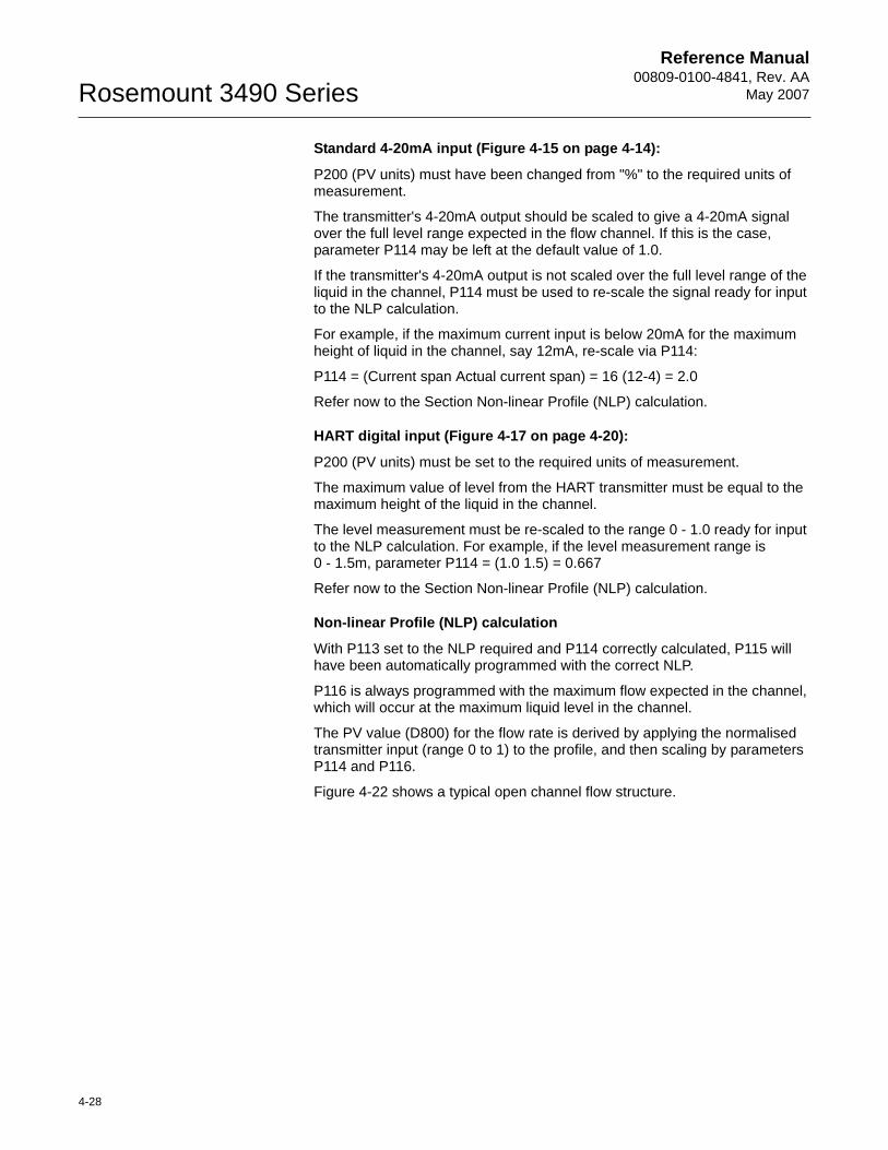
Reference Manual00809-0100-4841, Rev. AA
May 2007Rosemount 3490 Series
4-28
Standard 4-20mA input (Figure 4-15 on page 4-14):
P200 (PV units) must have been changed from "%" to the required units of measurement.
The transmitter's 4-20mA output should be scaled to give a 4-20mA signal over the full level range expected in the flow channel. If this is the case, parameter P114 may be left at the default value of 1.0.
If the transmitter's 4-20mA output is not scaled over the full level range of the liquid in the channel, P114 must be used to re-scale the signal ready for input to the NLP calculation.
For example, if the maximum current input is below 20mA for the maximum height of liquid in the channel, say 12mA, re-scale via P114:
P114 = (Current span Actual current span) = 16 (12-4) = 2.0
Refer now to the Section Non-linear Profile (NLP) calculation.
HART digital input (Figure 4-17 on page 4-20):
P200 (PV units) must be set to the required units of measurement.
The maximum value of level from the HART transmitter must be equal to the maximum height of the liquid in the channel.
The level measurement must be re-scaled to the range 0 - 1.0 ready for input to the NLP calculation. For example, if the level measurement range is 0 - 1.5m, parameter P114 = (1.0 1.5) = 0.667
Refer now to the Section Non-linear Profile (NLP) calculation.
Non-linear Profile (NLP) calculation
With P113 set to the NLP required and P114 correctly calculated, P115 will have been automatically programmed with the correct NLP.
P116 is always programmed with the maximum flow expected in the channel, which will occur at the maximum liquid level in the channel.
The PV value (D800) for the flow rate is derived by applying the normalised transmitter input (range 0 to 1) to the profile, and then scaling by parameters P114 and P116.
Figure 4-22 shows a typical open channel flow structure.
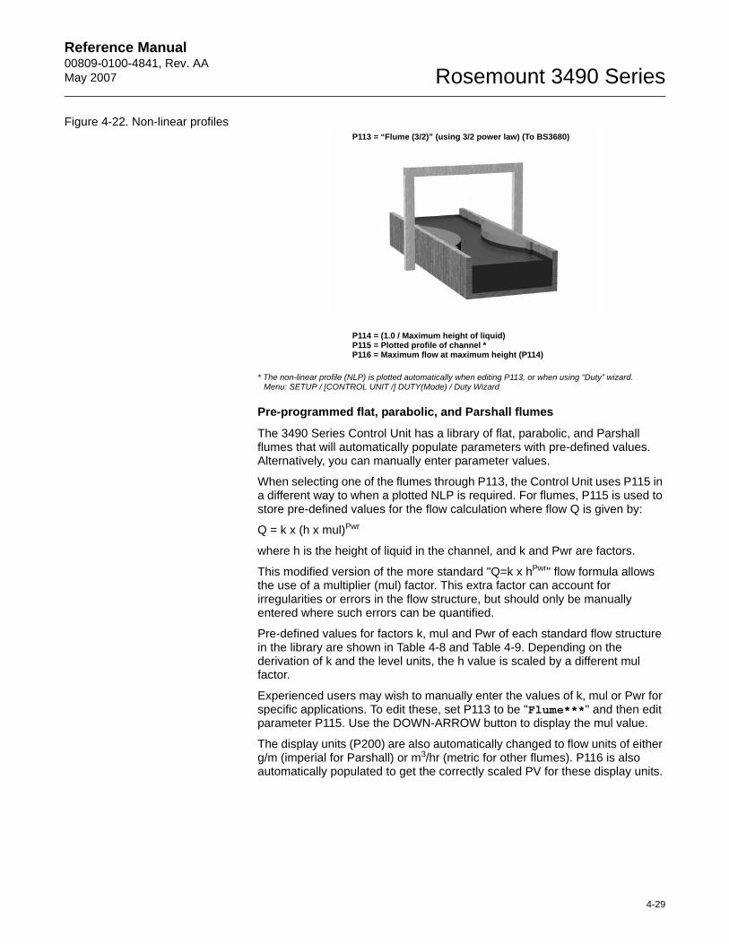
Reference Manual 00809-0100-4841, Rev. AA May 2007
4-29
Rosemount 3490 Series
Figure 4-22. Non-linear profiles
* The non-linear profile (NLP) is plotted automatically when editing P113, or when using “Duty” wizard.Menu: SETUP / [CONTROL UNIT /] DUTY(Mode) / Duty Wizard
Pre-programmed flat, parabolic, and Parshall flumes
The 3490 Series Control Unit has a library of flat, parabolic, and Parshall flumes that will automatically populate parameters with pre-defined values. Alternatively, you can manually enter parameter values.
When selecting one of the flumes through P113, the Control Unit uses P115 in a different way to when a plotted NLP is required. For flumes, P115 is used to store pre-defined values for the flow calculation where flow Q is given by:
Q = k x (h x mul)Pwr
where h is the height of liquid in the channel, and k and Pwr are factors.
This modified version of the more standard "Q=k x hPwr" flow formula allows the use of a multiplier (mul) factor. This extra factor can account for irregularities or errors in the flow structure, but should only be manually entered where such errors can be quantified.
Pre-defined values for factors k, mul and Pwr of each standard flow structure in the library are shown in Table 4-8 and Table 4-9. Depending on the derivation of k and the level units, the h value is scaled by a different mul factor.
Experienced users may wish to manually enter the values of k, mul or Pwr for specific applications. To edit these, set P113 to be "Flume***" and then edit parameter P115. Use the DOWN-ARROW button to display the mul value.
The display units (P200) are also automatically changed to flow units of either g/m (imperial for Parshall) or m3/hr (metric for other flumes). P116 is also automatically populated to get the correctly scaled PV for these display units.
P113 = “Flume (3/2)” (using 3/2 power law) (To BS3680)
P114 = (1.0 / Maximum height of liquid)P115 = Plotted profile of channel *P116 = Maximum flow at maximum height (P114)
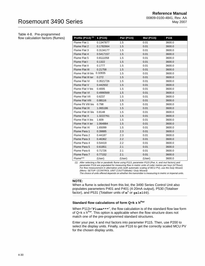
Reference Manual00809-0100-4841, Rev. AA
May 2007Rosemount 3490 Series
4-30
Table 4-8. Pre-programmed flow calculation factors (flumes)
NOTE:When a flume is selected from this list, the 3490 Series Control Unit also populates parameters P401 and P401 (4-20mA output), P530 (Totaliser factor), and P531 (Totaliser units of m3 or galx100).
Standard flow calculations of form Q=k x hPwr
When P113=“Flume***”, the flow calculation is of the standard flow law form of Q=k x hPwr. This option is applicable when the flow structure does not match one of the pre-programmed standard structures.
Enter your pwr, k and mul factors into parameter P115. Then, use P200 to select the display units. Finally, use P116 to get the correctly scaled MCU PV for the chosen display units.
Profile (P113) (1)
(1) After selecting a flat or parabolic flume using P113, parameter P115 (Pwr, k, and mul factors) and parameter P116 are populated for measuring flow in metric units of cubic metres per hour (m3/hour). For flow measurement in alternative units (with automatic scaling of MCU PV), use the Duty Wizard.(Menu: SETUP / [CONTROL UNIT /] DUTY(Mode) / Duty Wizard)The choice of units offered depends on whether the transmitter is measuring in metric or imperial units.
k (P115) Pwr (P115) Mul (P115) P116Flume Flat 1 0.1347877 1.5 0.01 3600.0Flume Flat 2 0.1782664 1.5 0.01 3600.0Flume Flat 3 0.3134177 1.5 0.01 3600.0Flume Flat 4 0.5417157 1.5 0.01 3600.0Flume Flat 5 0.8111058 1.5 0.01 3600.0Flume Flat I 0.1322 1.5 0.01 3600.0Flume Flat II 0.1777 1.5 0.01 3600.0Flume Flat III 0.21758 1.5 0.01 3600.0Flume Flat III bis 0.32835 1.5 0.01 3600.0Flume Flat III ter 0.272 1.5 0.01 3600.0Flume Flat IV 0.3521726 1.5 0.01 3600.0Flume Flat V 0.442932 1.5 0.01 3600.0Flume Flat V bis 0.4005 1.5 0.01 3600.0Flume Flat VI 0.4990569 1.5 0.01 3600.0Flume Flat VII 0.6237 1.5 0.01 3600.0Flume Flat VIII 0.88116 1.5 0.01 3600.0Flume Flt VIII bis 0.798 1.5 0.01 3600.0Flume Flat IX 1.065186 1.5 0.01 3600.0Flume Flat IX bis 0.8148 1.5 0.01 3600.0Flume Flat X 1.3222761 1.5 0.01 3600.0Flume Flat X bis 1.609 1.5 0.01 3600.0Flume Flat X ter 1.064884 1.5 0.01 3600.0Flume Flat XI 1.65099 1.5 0.01 3600.0Flume Para 1 0.39885 2.3 0.01 3600.0Flume Para 2 0.44187 2.3 0.01 3600.0Flume Para 3 0.46362 2.2 0.01 3600.0Flume Para 4 0.54419 2.2 0.01 3600.0Flume Para 5 0.61851 2.1 0.01 3600.0Flume Para 6 0.71726 2.1 0.01 3600.0Flume Para 7 0.77152 2.1 0.01 3600.0Flume*** (User) (User) (User) 3600.0
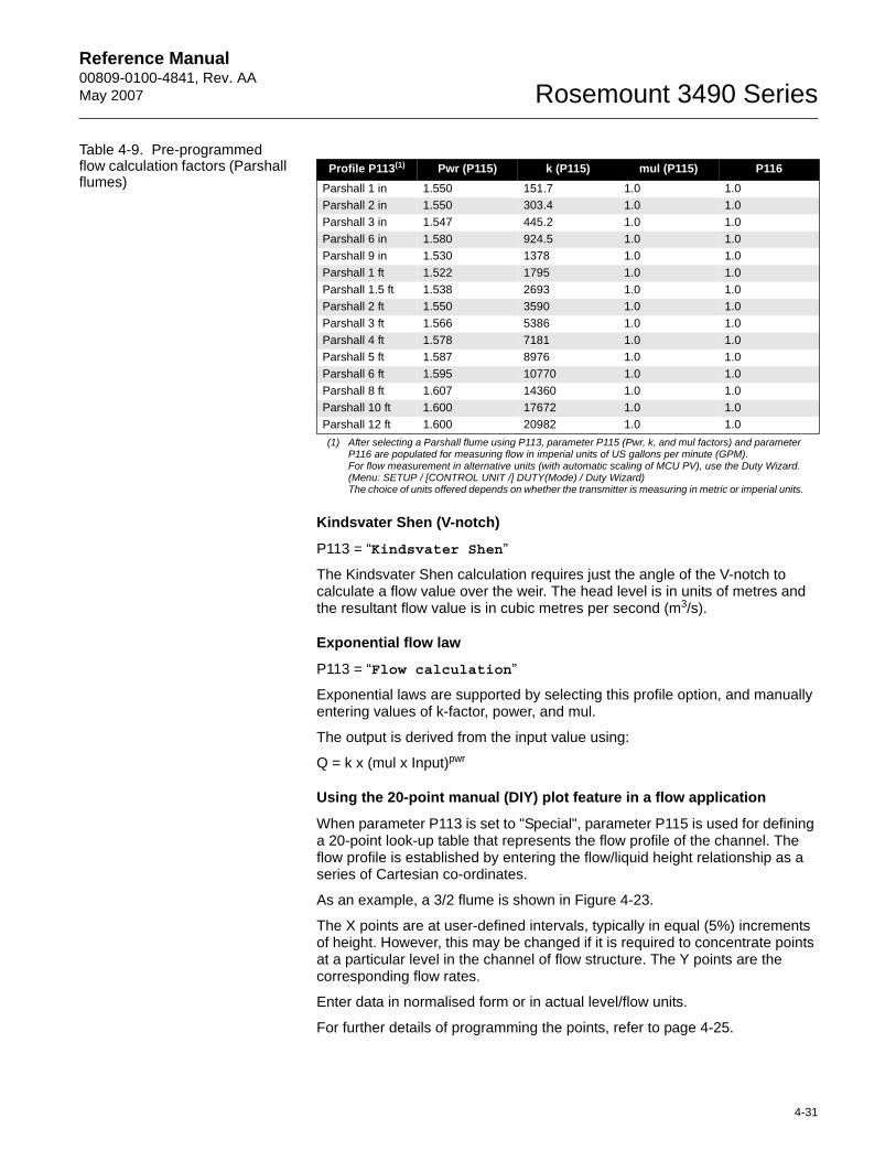
Reference Manual 00809-0100-4841, Rev. AA May 2007
4-31
Rosemount 3490 Series
Table 4-9. Pre-programmed flow calculation factors (Parshall flumes)
Kindsvater Shen (V-notch)
P113 = “Kindsvater Shen”
The Kindsvater Shen calculation requires just the angle of the V-notch to calculate a flow value over the weir. The head level is in units of metres and the resultant flow value is in cubic metres per second (m3/s).
Exponential flow law
P113 = “Flow calculation”
Exponential laws are supported by selecting this profile option, and manually entering values of k-factor, power, and mul.
The output is derived from the input value using:
Q = k x (mul x Input)pwr
Using the 20-point manual (DIY) plot feature in a flow application
When parameter P113 is set to "Special", parameter P115 is used for defining a 20-point look-up table that represents the flow profile of the channel. The flow profile is established by entering the flow/liquid height relationship as a series of Cartesian co-ordinates.
As an example, a 3/2 flume is shown in Figure 4-23.
The X points are at user-defined intervals, typically in equal (5%) increments of height. However, this may be changed if it is required to concentrate points at a particular level in the channel of flow structure. The Y points are the corresponding flow rates.
Enter data in normalised form or in actual level/flow units.
For further details of programming the points, refer to page 4-25.
Profile P113(1)
(1) After selecting a Parshall flume using P113, parameter P115 (Pwr, k, and mul factors) and parameter P116 are populated for measuring flow in imperial units of US gallons per minute (GPM). For flow measurement in alternative units (with automatic scaling of MCU PV), use the Duty Wizard. (Menu: SETUP / [CONTROL UNIT /] DUTY(Mode) / Duty Wizard)The choice of units offered depends on whether the transmitter is measuring in metric or imperial units.
Pwr (P115) k (P115) mul (P115) P116Parshall 1 in 1.550 151.7 1.0 1.0Parshall 2 in 1.550 303.4 1.0 1.0Parshall 3 in 1.547 445.2 1.0 1.0Parshall 6 in 1.580 924.5 1.0 1.0Parshall 9 in 1.530 1378 1.0 1.0Parshall 1 ft 1.522 1795 1.0 1.0Parshall 1.5 ft 1.538 2693 1.0 1.0Parshall 2 ft 1.550 3590 1.0 1.0Parshall 3 ft 1.566 5386 1.0 1.0Parshall 4 ft 1.578 7181 1.0 1.0Parshall 5 ft 1.587 8976 1.0 1.0Parshall 6 ft 1.595 10770 1.0 1.0Parshall 8 ft 1.607 14360 1.0 1.0Parshall 10 ft 1.600 17672 1.0 1.0Parshall 12 ft 1.600 20982 1.0 1.0
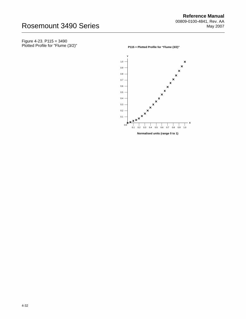
Reference Manual00809-0100-4841, Rev. AA
May 2007Rosemount 3490 Series
4-32
Figure 4-23. P115 = 3490 Plotted Profile for "Flume (3/2)"
0.1
0.2
0.3
0.4
0.5
0.6
0.7
0.8
0.9
1.0
0.1 0.2 0.3 0.4 0.5 0.6 0.7 0.8 0.9 1.00.0
Y
X
Normalised units (range 0 to 1)
P115 = Plotted Profile for “Flume (3/2)”
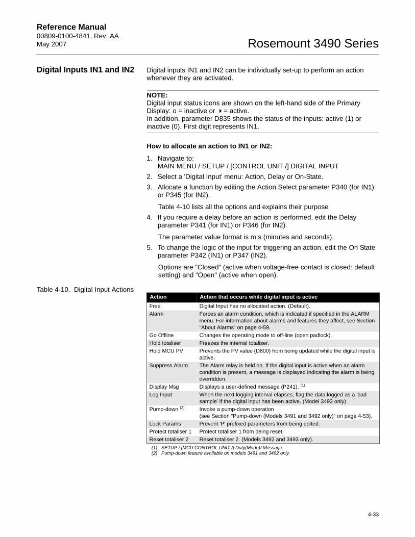
Reference Manual 00809-0100-4841, Rev. AA May 2007
4-33
Rosemount 3490 Series
Digital Inputs IN1 and IN2 Digital inputs IN1 and IN2 can be individually set-up to perform an action whenever they are activated.
NOTE:Digital input status icons are shown on the left-hand side of the Primary Display: o = inactive or = active. In addition, parameter D835 shows the status of the inputs: active (1) or inactive (0). First digit represents IN1.
How to allocate an action to IN1 or IN2:
1. Navigate to: MAIN MENU / SETUP / [CONTROL UNIT /] DIGITAL INPUT
2. Select a 'Digital Input' menu: Action, Delay or On-State.3. Allocate a function by editing the Action Select parameter P340 (for IN1)
or P345 (for IN2).
Table 4-10 lists all the options and explains their purpose4. If you require a delay before an action is performed, edit the Delay
parameter P341 (for IN1) or P346 (for IN2).
The parameter value format is m:s (minutes and seconds).5. To change the logic of the input for triggering an action, edit the On State
parameter P342 (IN1) or P347 (IN2).
Options are "Closed" (active when voltage-free contact is closed: default setting) and "Open" (active when open).
Table 4-10. Digital Input ActionsAction Action that occurs while digital input is activeFree Digital Input has no allocated action. (Default).Alarm Forces an alarm condition, which is indicated if specified in the ALARM
menu. For information about alarms and features they affect, see Section “About Alarms“ on page 4-59.
Go Offline Changes the operating mode to off-line (open padlock).Hold totaliser Freezes the internal totaliser.Hold MCU PV Prevents the PV value (D800) from being updated while the digital input is
active.Suppress Alarm The Alarm relay is held on. If the digital input is active when an alarm
condition is present, a message is displayed indicating the alarm is being overridden.
Display Msg Displays a user-defined message (P241). (1)
(1) SETUP / [MCU CONTROL UNIT /] Duty(Mode)/ Message.
Log Input When the next logging interval elapses, flag the data logged as a 'bad sample' if the digital input has been active. (Model 3493 only)
Pump-down (2)
(2) Pump-down feature available on models 3491 and 3492 only.
Invoke a pump-down operation(see Section “Pump-down (Models 3491 and 3492 only)“ on page 4-53).
Lock Params Prevent 'P' prefixed parameters from being edited.Protect totaliser 1 Protect totaliser 1 from being reset.Reset totaliser 2 Reset totaliser 2. (Models 3492 and 3493 only).
Reference Manual00809-0100-4841, Rev. AA
May 2007Rosemount 3490 Series
4-34
Logging (3493 Only) Menu: MAIN MENU / SETUP / [CONTROL UNIT /] LOGGING
Overview
Model 3493 will log up to 7000 events at regular intervals. An event is the value of a parameter. The parameter to be logged is the one selected for the middle section of the Primary Display (see “Primary Display Options“ on page 4-71). This parameter is typically the MCU Primary Variable (MCU PV).
If model 3493 has been set-up to totalise the parameter value, the daily value of the totaliser at midnight is also logged. Up to 60 midnight totalised values will be held in memory. (This is in addition to the memory for 7000 events.)
In addition, the maximum instantaneous value of the parameter recorded in each 24-hour period is logged.
Logged data may be downloaded at any time using the RS232 data port socket provided for connection details (see “RS232 Connections“ on page 3-13). You can download data using a PC with optional logger software.
NOTE:See “Serial Communications“ on page 4-73 for associated parameters.
Model 3493 gives a visual indication that logging of data is underway by flashing "LOG" in the bottom, right-hand corner of the Primary Display.
P590: Logging Interval
The logging interval is the period over which the parameter-to-be-logged(e.g. MCU PV) is sampled every 5 seconds and then averaged at the end. The averaged value is then logged.
An interval value of 15 minutes will log the averaged value at 15-minute intervals, which equates to 50 days elapsed time.
P591: Fast Log Mode
If the (logged) parameter value exceeds a user-entered value (P591), model 3493 automatically moves to a fast log mode and then logs the PV once every minute until the (logged) parameter value falls below that user-entered value. Fast log values are tagged, and so are easily identified when examining logged data.
P593: Low Memory Alarm
The user may allocate an alarm to indicate when the memory remaining falls to a user-defined percentage (P593). The user must also set the action to be taken when this occurs. A choice of activating a relay, driving the output current to a set level, or doing both is available (P542).
If no action is taken, the memory will fill, and then logged data will either be overwritten or the logging will stop, as determined by parameter P592.
Parameter D846 shows the percentage of free memory remaining for data logging.
P592: Do/Do not Overwrite Old Data
Once the logging memory is full, there is a choice to continue logging, in which case the earliest data is overwritten, or logging may be stopped at that time.
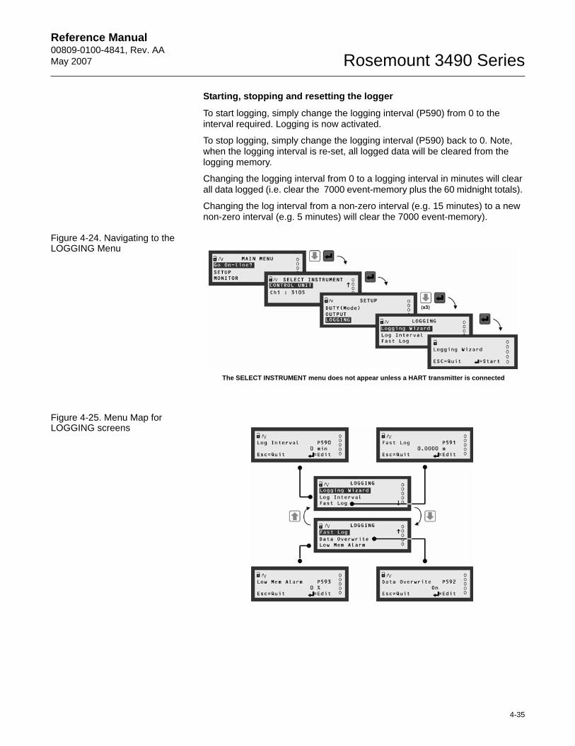
Reference Manual 00809-0100-4841, Rev. AA May 2007
4-35
Rosemount 3490 Series
Starting, stopping and resetting the logger
To start logging, simply change the logging interval (P590) from 0 to the interval required. Logging is now activated.
To stop logging, simply change the logging interval (P590) back to 0. Note, when the logging interval is re-set, all logged data will be cleared from the logging memory.
Changing the logging interval from 0 to a logging interval in minutes will clear all data logged (i.e. clear the 7000 event-memory plus the 60 midnight totals).
Changing the log interval from a non-zero interval (e.g. 15 minutes) to a new non-zero interval (e.g. 5 minutes) will clear the 7000 event-memory).
Figure 4-24. Navigating to the LOGGING Menu
Figure 4-25. Menu Map for LOGGING screens
The SELECT INSTRUMENT menu does not appear unless a HART transmitter is connected
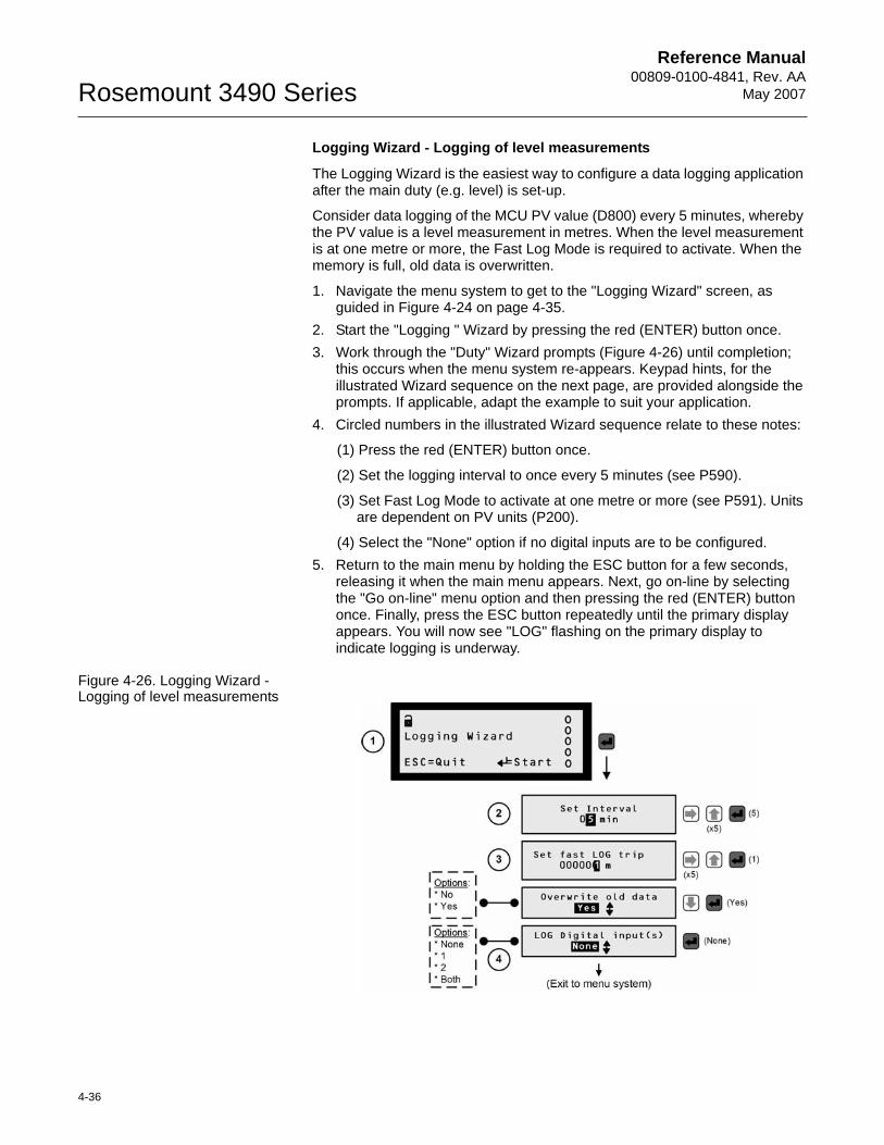
Reference Manual00809-0100-4841, Rev. AA
May 2007Rosemount 3490 Series
4-36
Logging Wizard - Logging of level measurements
The Logging Wizard is the easiest way to configure a data logging application after the main duty (e.g. level) is set-up.
Consider data logging of the MCU PV value (D800) every 5 minutes, whereby the PV value is a level measurement in metres. When the level measurement is at one metre or more, the Fast Log Mode is required to activate. When the memory is full, old data is overwritten.
1. Navigate the menu system to get to the "Logging Wizard" screen, as guided in Figure 4-24 on page 4-35.
2. Start the "Logging " Wizard by pressing the red (ENTER) button once.3. Work through the "Duty" Wizard prompts (Figure 4-26) until completion;
this occurs when the menu system re-appears. Keypad hints, for the illustrated Wizard sequence on the next page, are provided alongside the prompts. If applicable, adapt the example to suit your application.
4. Circled numbers in the illustrated Wizard sequence relate to these notes:
(1) Press the red (ENTER) button once.
(2) Set the logging interval to once every 5 minutes (see P590).
(3) Set Fast Log Mode to activate at one metre or more (see P591). Units are dependent on PV units (P200).
(4) Select the "None" option if no digital inputs are to be configured.5. Return to the main menu by holding the ESC button for a few seconds,
releasing it when the main menu appears. Next, go on-line by selecting the "Go on-line" menu option and then pressing the red (ENTER) button once. Finally, press the ESC button repeatedly until the primary display appears. You will now see "LOG" flashing on the primary display to indicate logging is underway.
Figure 4-26. Logging Wizard - Logging of level measurements
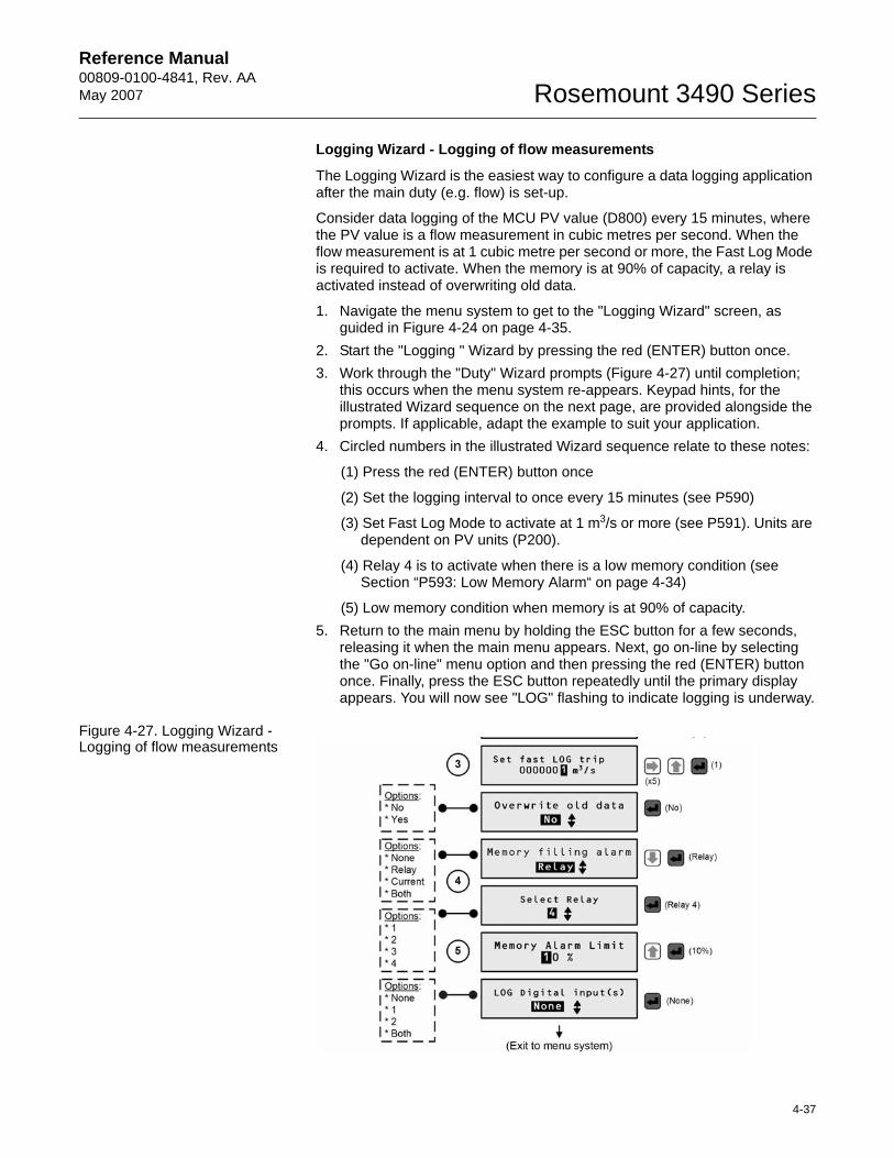
Reference Manual 00809-0100-4841, Rev. AA May 2007
4-37
Rosemount 3490 Series
Logging Wizard - Logging of flow measurements
The Logging Wizard is the easiest way to configure a data logging application after the main duty (e.g. flow) is set-up.
Consider data logging of the MCU PV value (D800) every 15 minutes, where the PV value is a flow measurement in cubic metres per second. When the flow measurement is at 1 cubic metre per second or more, the Fast Log Mode is required to activate. When the memory is at 90% of capacity, a relay is activated instead of overwriting old data.
1. Navigate the menu system to get to the "Logging Wizard" screen, as guided in Figure 4-24 on page 4-35.
2. Start the "Logging " Wizard by pressing the red (ENTER) button once.3. Work through the "Duty" Wizard prompts (Figure 4-27) until completion;
this occurs when the menu system re-appears. Keypad hints, for the illustrated Wizard sequence on the next page, are provided alongside the prompts. If applicable, adapt the example to suit your application.
4. Circled numbers in the illustrated Wizard sequence relate to these notes:
(1) Press the red (ENTER) button once
(2) Set the logging interval to once every 15 minutes (see P590)
(3) Set Fast Log Mode to activate at 1 m3/s or more (see P591). Units are dependent on PV units (P200).
(4) Relay 4 is to activate when there is a low memory condition (see Section “P593: Low Memory Alarm“ on page 4-34)
(5) Low memory condition when memory is at 90% of capacity. 5. Return to the main menu by holding the ESC button for a few seconds,
releasing it when the main menu appears. Next, go on-line by selecting the "Go on-line" menu option and then pressing the red (ENTER) button once. Finally, press the ESC button repeatedly until the primary display appears. You will now see "LOG" flashing to indicate logging is underway.
Figure 4-27. Logging Wizard - Logging of flow measurements
Reference Manual00809-0100-4841, Rev. AA
May 2007Rosemount 3490 Series
4-38
Current Output NOTE: The current output of the 3490 Series Control Unit is FROZEN when the unit is in the "off-line" mode.
The Current Output Channel
The Current Output channel is for transmitting the MCU PV value (D800) as a 4-20mA signal.
For example, consider a PV value of 5 metres and the PV range is 0 to 10 metres. This would mean 0 metres is represented by a 4mA signal (0%), 10 metres is represented by 20mA signal (100%) and 5 metres is represented by a 12mA signal (50%). Therefore, the Current Output channel would output the PV value as a 4-12mA signal.
Programming involves specifying the PV range with low range (minimum) and upper range (maximum) values.
Menu:MAIN MENU / SETUP / [CONTROL UNIT /] OUTPUT / CURRENT OUTPUT
P400 Low Range Val (Factory default is 0.0)
This is the PV value represented by 4mA.
P401 Up Range Val (Factory default is 100.0)
This is the PV value represented by 20mA.
P402 Alarm Actions (Factory default is 3.6mA)
Optional parameter for determining how an alarm, if selected in the ALARM menu, is indicated on the Current Output channel. Options for P402 are:• "3.6mA" - fix current output to 3.6 mA to force a low current limit alarm.• "3.75mA" - fix current output to 3.75 mA to force a low current limit alarm.• "Hold"- freeze the current output at the present value.• "21mA"- fix current output to 21 mA to force high current limit alarm.• "21.75mA"- fix current output to 21.75 mA to force high current limit alarm.• "22.5mA"- fix current output to 22.5 mA to force high current limit alarm.
NOTE:The “3.75mA” and “21.75mA” options are the Rosemount standard. The “3.6 mA” and “22.5 mA” options are the NAMUR NE43 standard.
Alarms and indications are as explained in “About Alarms“ on page 4-59. See also Table 4-15 on page 4-61 for summary of reporting methods for Alarms.
NOTE:There is another alarm condition when the current output has reached the linear limit i.e. saturated. For the Rosemount Standard, this is ≤ 3.9mA or≥ 20.8mA. For the NAMUR NE43 standard, this is ≤ 3.8mA or ≥ 20.5mA.
Reference Manual 00809-0100-4841, Rev. AA May 2007
4-39
Rosemount 3490 Series
P404 mA Mode (Factory default is “Instantaneous”)
On model 3493, this optional parameter is for assigning the Current Output to follow a rolling average of the calculated MCU PV (typically flow). To do this, select the Rolling option.
The time period for the rolling averaging is defined using P590, which is also for defining the logging interval (see “Logging (3493 Only)“ on page 4-34).
P210 MCU PV Damping (Factory default is 0)
The 3490’s current output is proportional to the calculated MCU PV. It is possible to apply damping to the MCU PV using P210, which will have the effect of damping the current output.
Relays NOTE:Relay states are frozen when 3490 Series Control Unit is in "off-line" mode.
Menu Navigation List: (for locating relay parameters)
1. MAIN MENU / SETUP / [CONTROL UNIT /] OUTPUT / RELAY2. MAIN MENU / SETUP / [CONTROL UNIT /] DUTY(Mode) / OVERRIDES3. MAIN MENU / SETUP / [CONTROL UNIT /] DUTY(Mode) / CUSTOM
Overview of Relay Functions
Relay outputs 1 to 4 are normally On Point / Off Point control relays which may be used to start/stop pumps or open/close valves at different levels. They normally energise at one level and de-energise at a different level. For further details, see Section “On/Off Point Control“ on page 4-41.
Alternatively, they can be programmed as out-of-limit alarms; they energise between defined points and will de-energise outside those points. They may also be programmed to perform a variety of auto-sequences and auxiliary functions, such as pump-down operations, pump rotations to equalise wear, and de-sludge/cleaning. For further details, see Section “Alternative Duties“ on page 4-42.
Relay output 5 is normally a fail safe fault relay but may be re-allocated to another duty.
NOTE:Relays are frozen while the 3490 Series Control Unit is off-line, preventing all relay operations apart from Totaliser and Sampler relays.
Relay Wizard
Relay outputs can be set-up easily using the "Relay" Wizard, accessible by navigating to the RELAYS menu screen. The Wizard also forms a part of the "Duty" Wizard.
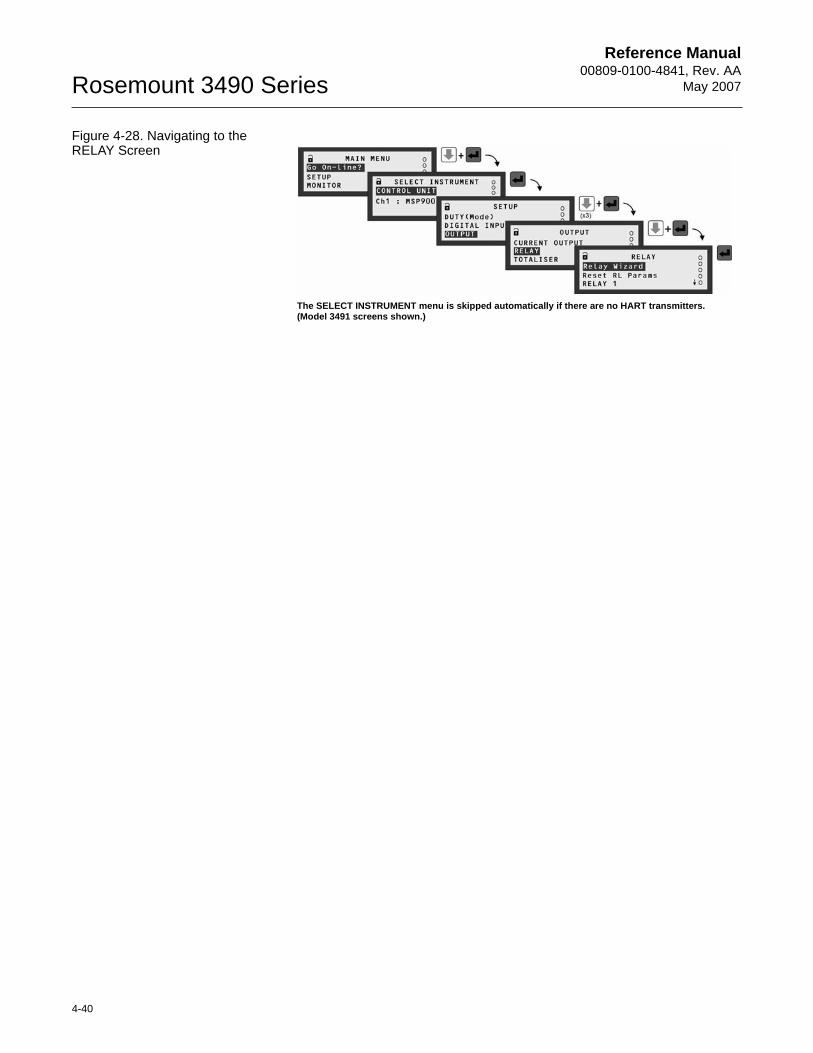
Reference Manual00809-0100-4841, Rev. AA
May 2007Rosemount 3490 Series
4-40
Figure 4-28. Navigating to the RELAY Screen
The SELECT INSTRUMENT menu is skipped automatically if there are no HART transmitters. (Model 3491 screens shown.)
Reference Manual 00809-0100-4841, Rev. AA May 2007
4-41
Rosemount 3490 Series
Relay (RL) Status
The relay status icons on the primary display have the following meanings:
= energised: Relay is presently energised.
0 = de-energised: Relay is presently de-energised.
A = Alarm: Relay allocated to alarm duty (see page 4-59 about alarms.)
S = Sampler: Relay is allocated to sampling duty.
T = Totalising: Relay is allocated to totalising duty.
Relay parameter reset
To reset all relay parameters to their factory defaults, do the following:4. Navigate to:
MAIN MENU / SETUP / [C. UNIT /] OUTPUT / RELAY / Reset RL param5. If you wish to proceed, press the red (ENTER) button once. (Otherwise,
use the ESC button to exit to the menu).6. Wait until the "Please wait…" message disappears.7. Press the ESC button to return to the menu.
NOTE:Setting the relays to their factory default state in this way does NOT reset any other parameters to their default state.
On/Off Point Control
Relay outputs 1 to 4 can be set-up to be On Point and Off Point control relays:
Menu: MAIN MENU / SETUP / [CONTROL UNIT /] OUTPUT / RELAY
Relay 1 (RL1):
If mode is "Set Point" (P410) - relay energised at P411 (On) and de-energised at P412 (Off)
Relay 2 (RL2):
If mode is "Set Point" (P420) - relay energised at P421 (On) and de-energised at P422 (Off)
Relay 3 (RL3):
If mode is "Set Point" (P430) - relay energised at P431 (On) and de-energised at P432 (Off)
Relay 4 (RL4):
If mode is "Set Point" (P440) - relay energised at P441 (On) and de-energised at P442 (Off)
In a basic emptying application, the On point (e.g. P411) is programmed to be greater than the Off point (e.g. P412). Relay 1 in this case will energise when the PV value (D800) exceeds the On point (P411) and de-energise when the PV value drops below the Off point (P412).
Reference Manual00809-0100-4841, Rev. AA
May 2007Rosemount 3490 Series
4-42
In a basic filling applications, the On point (e.g. P411) is programmed to be less than the Off point (e.g. P412). Relay 1 in this case will energise when the PV value (D800) drops below the On point (P411) and de-energise when the PV value rises above the Off point (P412).
When the relay mode is "Set Point" (as above), the PV value is used to control the relays. There are set point modes for the SV value (D801), TV value (D802) and FV value (D803). For details of these, see Section “Transmitter inputs to the 3490“ on page 4-12.
Relay Safeguard Options
Menu: MAIN MENU / SETUP / [CONTROL UNIT /] OUTPUT / RELAY
P413 RL1 Min On (Factory default: 0:00 m:s)
Defines the minimum time (minutes and seconds) that relay RL1 will stay energised before de-energising. This is an optional override (safeguard) to allow sufficient time for connected equipment to respond.
P414 RL1 Max On Factory default: 0:00 m:s)
Defines the maximum time (minutes and seconds) that relay RL1 will stay energised before de-energising. This is an optional override (safeguard) to prevent overuse of connected equipment.
P415 RL1 Min Off (Factory default: 0:00 m:s)
Defines the minimum time (minutes and seconds) that relay RL1 will stay de-energised before energising. This is an optional override (safeguard) to avoid overuse of connected equipment.
P423 to P425 are the equivalents for relay RL2
P433 to P435 are the equivalents for relay RL3
P443 to P445 are the equivalents for relay RL4
P453 to P455 are the equivalents for relay RL5
Alternative Duties
Relays can perform alternative duties beside the "On/Off point control" operation described in Section “On/Off Point Control“ on page 4-41.
Menu: MAIN MENU / SETUP / [CONTROL UNIT /] OUTPUT / RELAY
P410 Relay 1 Mode (Factory default is "None")
P420 Relay 2 Mode (Factory default is "None")
P430 Relay 3 Mode (Factory default is "None")
P440 Relay 4 Mode (Factory default is "None")
P450 Relay 5 Mode (Factory default is "Fault")
Table 4-11 on page 4-43 lists all relay modes (duties) and what they do. Relay modes automatically enable and disable special control functions, special alarms and pumped volume totalising as shown in Table 4-12 on page 4-44. Descriptions of the relay modes and the auxiliary functions follow Table 4-12.
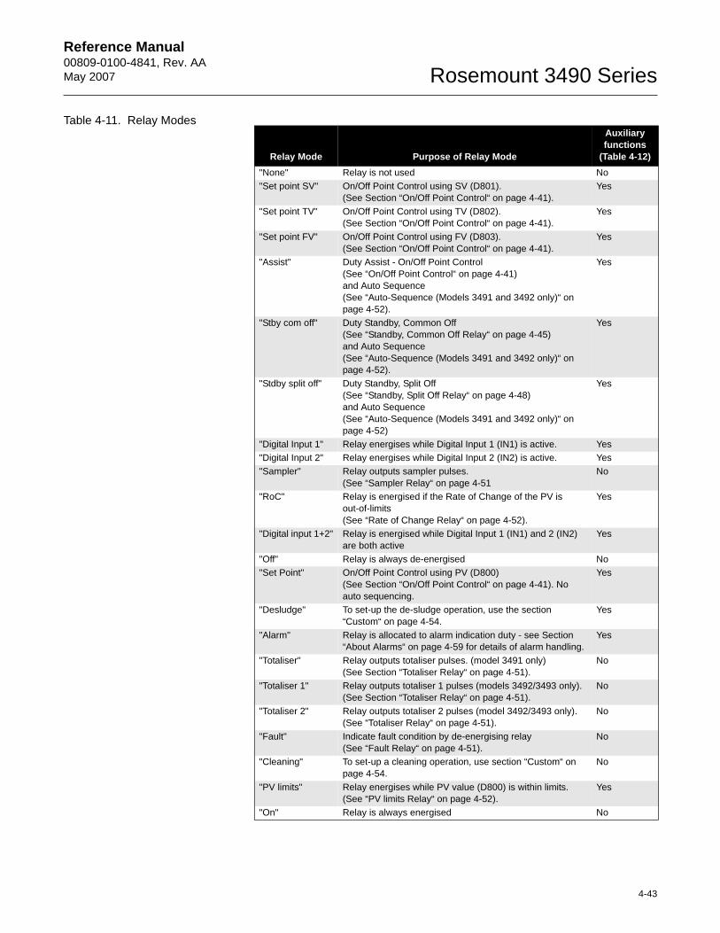
Reference Manual 00809-0100-4841, Rev. AA May 2007
4-43
Rosemount 3490 Series
Table 4-11. Relay Modes
Relay Mode Purpose of Relay Mode
Auxiliary functions
(Table 4-12)"None" Relay is not used No"Set point SV" On/Off Point Control using SV (D801).
(See Section “On/Off Point Control“ on page 4-41).Yes
"Set point TV" On/Off Point Control using TV (D802).(See Section “On/Off Point Control“ on page 4-41).
Yes
"Set point FV" On/Off Point Control using FV (D803).(See Section “On/Off Point Control“ on page 4-41).
Yes
"Assist" Duty Assist - On/Off Point Control(See “On/Off Point Control“ on page 4-41)and Auto Sequence(See “Auto-Sequence (Models 3491 and 3492 only)“ on page 4-52).
Yes
"Stby com off" Duty Standby, Common Off(See “Standby, Common Off Relay“ on page 4-45)and Auto Sequence(See “Auto-Sequence (Models 3491 and 3492 only)“ on page 4-52).
Yes
"Stdby split off" Duty Standby, Split Off (See “Standby, Split Off Relay“ on page 4-48)and Auto Sequence(See “Auto-Sequence (Models 3491 and 3492 only)“ on page 4-52)
Yes
"Digital Input 1" Relay energises while Digital Input 1 (IN1) is active. Yes"Digital Input 2" Relay energises while Digital Input 2 (IN2) is active. Yes"Sampler" Relay outputs sampler pulses.
(See “Sampler Relay“ on page 4-51No
"RoC" Relay is energised if the Rate of Change of the PV is out-of-limits (See “Rate of Change Relay“ on page 4-52).
Yes
"Digital input 1+2" Relay is energised while Digital Input 1 (IN1) and 2 (IN2) are both active
Yes
"Off" Relay is always de-energised No"Set Point" On/Off Point Control using PV (D800)
(See Section “On/Off Point Control“ on page 4-41). No auto sequencing.
Yes
"Desludge" To set-up the de-sludge operation, use the section “Custom“ on page 4-54.
Yes
"Alarm" Relay is allocated to alarm indication duty - see Section “About Alarms“ on page 4-59 for details of alarm handling.
Yes
"Totaliser" Relay outputs totaliser pulses. (model 3491 only)(See Section “Totaliser Relay“ on page 4-51).
No
"Totaliser 1" Relay outputs totaliser 1 pulses (models 3492/3493 only).(See Section “Totaliser Relay“ on page 4-51).
No
"Totaliser 2" Relay outputs totaliser 2 pulses (model 3492/3493 only).(See “Totaliser Relay“ on page 4-51).
No
"Fault" Indicate fault condition by de-energising relay(See “Fault Relay“ on page 4-51).
No
"Cleaning" To set-up a cleaning operation, use section “Custom“ on page 4-54.
No
"PV limits" Relay energises while PV value (D800) is within limits.(See “PV limits Relay“ on page 4-52).
Yes
"On" Relay is always energised No
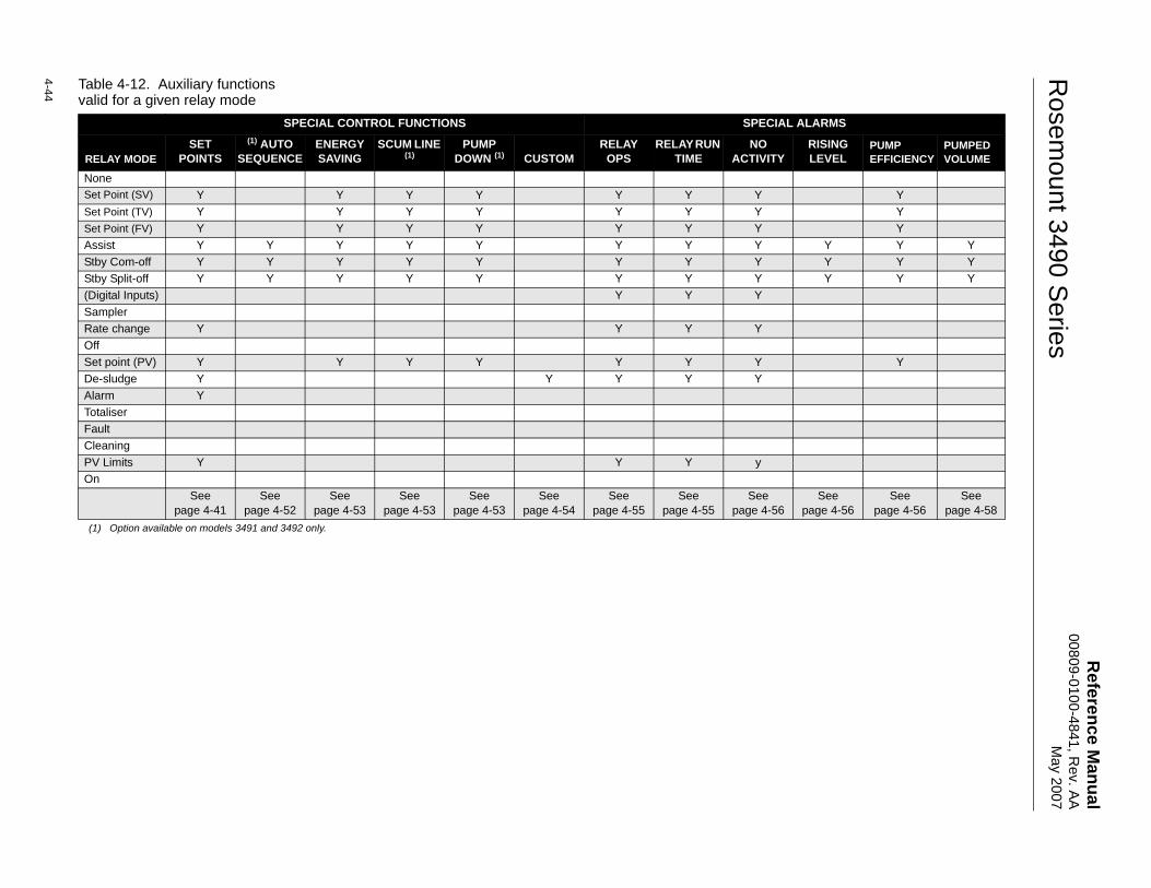
Reference M
anual00809-0100-4841, R
ev. AA
May 2007
Rosem
ount 3490 Series
4-44 Table 4-12. Auxiliary functions valid for a given relay mode
SPECIAL CONTROL FUNCTIONS SPECIAL ALARMS
RELAY MODESET
POINTS(1) AUTO
SEQUENCE ENERGY SAVING
SCUM LINE (1)
PUMP DOWN (1) CUSTOM
RELAYOPS
RELAY RUN TIME
NO ACTIVITY
RISING LEVEL
PUMP EFFICIENCY
PUMPED VOLUME
NoneSet Point (SV) Y Y Y Y Y Y Y YSet Point (TV) Y Y Y Y Y Y Y YSet Point (FV) Y Y Y Y Y Y Y YAssist Y Y Y Y Y Y Y Y Y Y YStby Com-off Y Y Y Y Y Y Y Y Y Y YStby Split-off Y Y Y Y Y Y Y Y Y Y Y(Digital Inputs) Y Y YSamplerRate change Y Y Y YOffSet point (PV) Y Y Y Y Y Y Y YDe-sludge Y Y Y Y YAlarm YTotaliserFaultCleaningPV Limits Y Y Y yOn
See page 4-41
See page 4-52
See page 4-53
See page 4-53
See page 4-53
See page 4-54
See page 4-55
See page 4-55
See page 4-56
See page 4-56
See page 4-56
See page 4-58
(1) Option available on models 3491 and 3492 only.
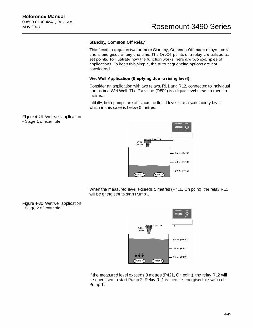
Reference Manual 00809-0100-4841, Rev. AA May 2007
4-45
Rosemount 3490 Series
Standby, Common Off Relay
This function requires two or more Standby, Common Off mode relays - only one is energised at any one time. The On/Off points of a relay are utilised as set points. To illustrate how the function works, here are two examples of applications. To keep this simple, the auto-sequencing options are not considered.
Wet Well Application (Emptying due to rising level):
Consider an application with two relays, RL1 and RL2, connected to individual pumps in a Wet Well. The PV value (D800) is a liquid level measurement in metres.
Initially, both pumps are off since the liquid level is at a satisfactory level, which in this case is below 5 metres.
Figure 4-29. Wet well application - Stage 1 of example
When the measured level exceeds 5 metres (P411, On point), the relay RL1 will be energised to start Pump 1.
Figure 4-30. Wet well application - Stage 2 of example
If the measured level exceeds 8 metres (P421, On point), the relay RL2 will be energised to start Pump 2. Relay RL1 is then de-energised to switch off Pump 1.
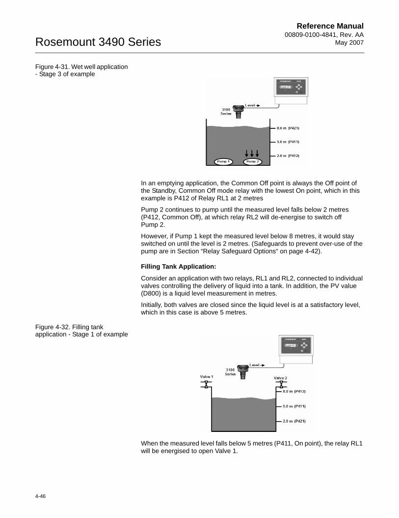
Reference Manual00809-0100-4841, Rev. AA
May 2007Rosemount 3490 Series
4-46
Figure 4-31. Wet well application - Stage 3 of example
In an emptying application, the Common Off point is always the Off point of the Standby, Common Off mode relay with the lowest On point, which in this example is P412 of Relay RL1 at 2 metres
Pump 2 continues to pump until the measured level falls below 2 metres (P412, Common Off), at which relay RL2 will de-energise to switch off Pump 2.
However, if Pump 1 kept the measured level below 8 metres, it would stay switched on until the level is 2 metres. (Safeguards to prevent over-use of the pump are in Section “Relay Safeguard Options“ on page 4-42).
Filling Tank Application:
Consider an application with two relays, RL1 and RL2, connected to individual valves controlling the delivery of liquid into a tank. In addition, the PV value (D800) is a liquid level measurement in metres.
Initially, both valves are closed since the liquid level is at a satisfactory level, which in this case is above 5 metres.
Figure 4-32. Filling tank application - Stage 1 of example
When the measured level falls below 5 metres (P411, On point), the relay RL1 will be energised to open Valve 1.
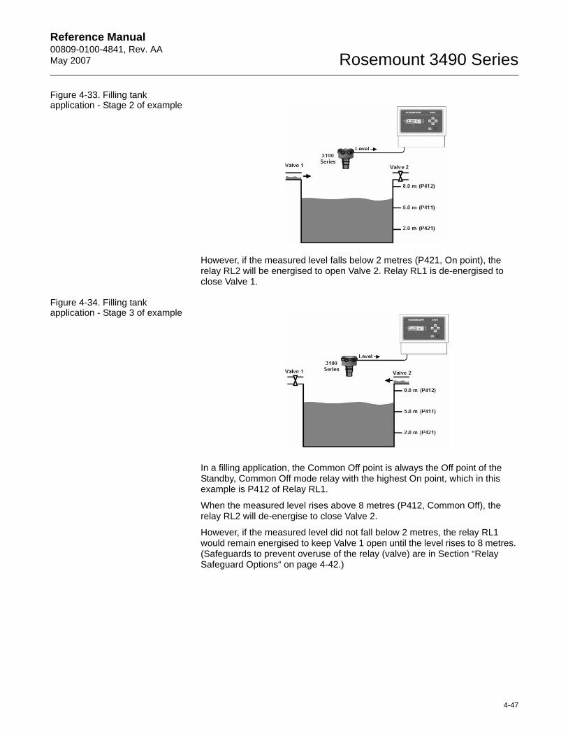
Reference Manual 00809-0100-4841, Rev. AA May 2007
4-47
Rosemount 3490 Series
Figure 4-33. Filling tank application - Stage 2 of example
However, if the measured level falls below 2 metres (P421, On point), the relay RL2 will be energised to open Valve 2. Relay RL1 is de-energised to close Valve 1.
Figure 4-34. Filling tank application - Stage 3 of example
In a filling application, the Common Off point is always the Off point of the Standby, Common Off mode relay with the highest On point, which in this example is P412 of Relay RL1.
When the measured level rises above 8 metres (P412, Common Off), the relay RL2 will de-energise to close Valve 2.
However, if the measured level did not fall below 2 metres, the relay RL1 would remain energised to keep Valve 1 open until the level rises to 8 metres. (Safeguards to prevent overuse of the relay (valve) are in Section “Relay Safeguard Options“ on page 4-42.)
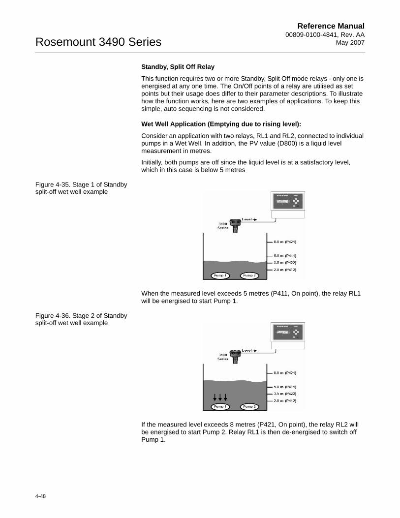
Reference Manual00809-0100-4841, Rev. AA
May 2007Rosemount 3490 Series
4-48
Standby, Split Off Relay
This function requires two or more Standby, Split Off mode relays - only one is energised at any one time. The On/Off points of a relay are utilised as set points but their usage does differ to their parameter descriptions. To illustrate how the function works, here are two examples of applications. To keep this simple, auto sequencing is not considered.
Wet Well Application (Emptying due to rising level):
Consider an application with two relays, RL1 and RL2, connected to individual pumps in a Wet Well. In addition, the PV value (D800) is a liquid level measurement in metres.
Initially, both pumps are off since the liquid level is at a satisfactory level, which in this case is below 5 metres
Figure 4-35. Stage 1 of Standby split-off wet well example
When the measured level exceeds 5 metres (P411, On point), the relay RL1 will be energised to start Pump 1.
Figure 4-36. Stage 2 of Standby split-off wet well example
If the measured level exceeds 8 metres (P421, On point), the relay RL2 will be energised to start Pump 2. Relay RL1 is then de-energised to switch off Pump 1.

Reference Manual 00809-0100-4841, Rev. AA May 2007
4-49
Rosemount 3490 Series
Figure 4-37. Stage 3 of Standby split-off wet well example
When the measured level falls below 3.5 metres (P422, Off point), relay RL2 will de-energise to switch off Pump 2.
Relay RL1 is then energised to start Pump 1 again.
When the measured level falls below 2 metres (P412, Off point), relay RL1 will de-energise to switch off Pump 1.
However, if Pump 1 kept the measured level below 8 metres, it would stay switched on until the level is 2 metres. (Safeguards to prevent overuse of the pump are in Section “Relay Safeguard Options“ on page 4-42.)
Filling Tank Application:
Consider an application with two relays, RL1 and RL2, connected to individual valves controlling the delivery of liquid into a tank. In addition, the PV value (D800) is a liquid level measurement in metres.
Initially, both valves are closed since the liquid level is at a satisfactory level, which in this case is above 5 metres.
Figure 4-38. Stage 1 of Standby split-off filling tank example
When the measured level falls below 5 metres (P411, On point), the relay RL1 will be energised to open Valve 1.
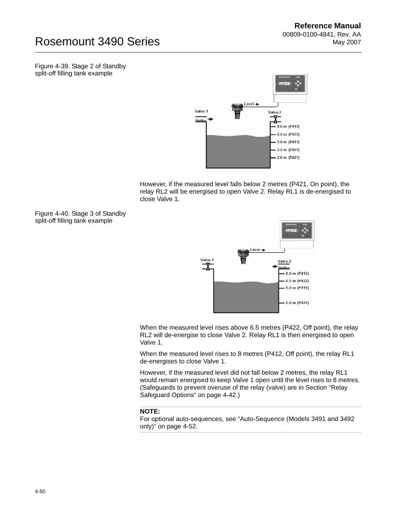
Reference Manual00809-0100-4841, Rev. AA
May 2007Rosemount 3490 Series
4-50
Figure 4-39. Stage 2 of Standby split-off filling tank example
However, if the measured level falls below 2 metres (P421, On point), the relay RL2 will be energised to open Valve 2. Relay RL1 is de-energised to close Valve 1.
Figure 4-40. Stage 3 of Standby split-off filling tank example
When the measured level rises above 6.5 metres (P422, Off point), the relay RL2 will de-energise to close Valve 2. Relay RL1 is then energised to open Valve 1.
When the measured level rises to 8 metres (P412, Off point), the relay RL1 de-energises to close Valve 1.
However, if the measured level did not fall below 2 metres, the relay RL1 would remain energised to keep Valve 1 open until the level rises to 8 metres. (Safeguards to prevent overuse of the relay (valve) are in Section “Relay Safeguard Options“ on page 4-42.)
NOTE:For optional auto-sequences, see “Auto-Sequence (Models 3491 and 3492 only)“ on page 4-52.
Reference Manual 00809-0100-4841, Rev. AA May 2007
4-51
Rosemount 3490 Series
Totaliser Relay
Menu:MAIN MENU / SETUP / [CONTROL UNIT /] OUTPUT / TOTALISER
Each time the internal totaliser count (D828) increments, a relay may be allocated to provide a pulse. The duration of the pulse may set via P534.
P534 Totaliser Pulse Width (Factory default is 100)
The duration controls both the 'On' time and the 'Off' time - i.e. the pulse width - and may be set to a value between 10ms and 2.5 seconds in steps of 10ms.
If the totaliser count is running faster than the relay can produce pulses, an internal accumulator stores the excess pulses; they will be produced by the Totaliser relay once the totaliser count rate reduces.
Sampler Relay
Sampler relays output pulses at a slower rate than a Totaliser relay. The Sampler relay can be used as a coarse totaliser or as a trigger to an external event.
Menu:MAIN MENU / SETUP / [CONTROL UNIT /] OUTPUT / TOTALISER
P535 Sampler Factor (Factory default is 0)
This is for defining the frequency of the Sampler pulse. For example, a value of 100 means that the Sampler relay outputs a single pulse for every 100th increment to the Totaliser Count (D828/D829). The pulse width is the same as selected for the Totaliser relay (P534). For information on setting up the totaliser, see page 4-62 onwards.
Fault Relay
A Fault relay is de-energised when a particular fault condition exists. Parameter D831 is a fault report and shows a list of active faults. Table 4-15 on page 4-61 has a summary of reporting methods for faults.
Menu: MAIN MENU / SETUP / [CONTROL UNIT /] OUTPUT / FAULT
P560 System Fault (Factory default is "Both")
The Fault relay is de-energised when there is a system fault and the option selected is "Both" or "Relay".
P561 CU Temp Fault (Factory default setting is "None")
The Fault relay is de-energised if the temperature of the CPU rises above 65°C, and the option selected is "Both" or "Relay". Parameter D844 shows the operating temperature of the 3490 Series Control Unit.
P562 Xmtr Fault (Factory default setting is "None")
The Fault relay is de-energised when the transmitter signals a fault and the option selected is "Both" or "Relay".
Faults can be indicated on the Current Output if you select the "Current" or "Both" options. See also the Alarm Action parameter (P402) description in Section “Current Output“ on page 4-38.
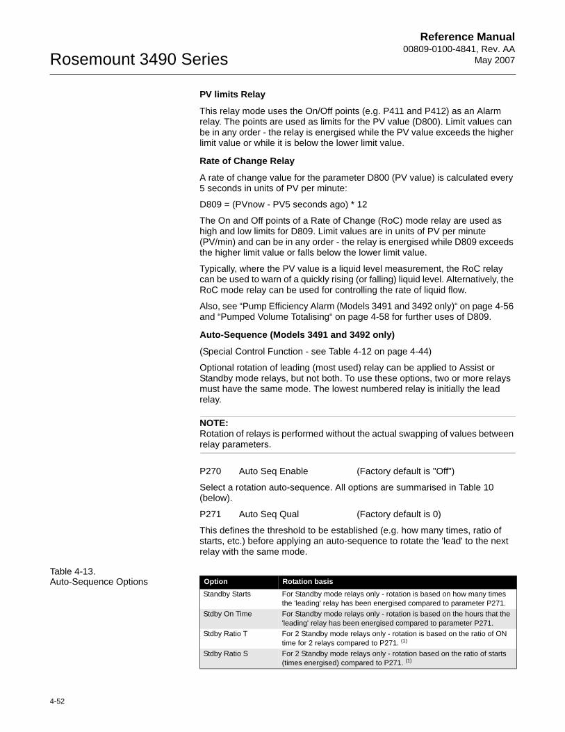
Reference Manual00809-0100-4841, Rev. AA
May 2007Rosemount 3490 Series
4-52
PV limits Relay
This relay mode uses the On/Off points (e.g. P411 and P412) as an Alarm relay. The points are used as limits for the PV value (D800). Limit values can be in any order - the relay is energised while the PV value exceeds the higher limit value or while it is below the lower limit value.
Rate of Change Relay
A rate of change value for the parameter D800 (PV value) is calculated every 5 seconds in units of PV per minute:
D809 = (PVnow - PV5 seconds ago) * 12
The On and Off points of a Rate of Change (RoC) mode relay are used as high and low limits for D809. Limit values are in units of PV per minute (PV/min) and can be in any order - the relay is energised while D809 exceeds the higher limit value or falls below the lower limit value.
Typically, where the PV value is a liquid level measurement, the RoC relay can be used to warn of a quickly rising (or falling) liquid level. Alternatively, the RoC mode relay can be used for controlling the rate of liquid flow.
Also, see “Pump Efficiency Alarm (Models 3491 and 3492 only)“ on page 4-56 and “Pumped Volume Totalising“ on page 4-58 for further uses of D809.
Auto-Sequence (Models 3491 and 3492 only)
(Special Control Function - see Table 4-12 on page 4-44)
Optional rotation of leading (most used) relay can be applied to Assist or Standby mode relays, but not both. To use these options, two or more relays must have the same mode. The lowest numbered relay is initially the lead relay.
NOTE:Rotation of relays is performed without the actual swapping of values between relay parameters.
P270 Auto Seq Enable (Factory default is "Off")
Select a rotation auto-sequence. All options are summarised in Table 10 (below).
P271 Auto Seq Qual (Factory default is 0)
This defines the threshold to be established (e.g. how many times, ratio of starts, etc.) before applying an auto-sequence to rotate the 'lead' to the next relay with the same mode.
Table 4-13. Auto-Sequence Options Option Rotation basis
Standby Starts For Standby mode relays only - rotation is based on how many times the 'leading' relay has been energised compared to parameter P271.
Stdby On Time For Standby mode relays only - rotation is based on the hours that the 'leading' relay has been energised compared to parameter P271.
Stdby Ratio T For 2 Standby mode relays only - rotation is based on the ratio of ON time for 2 relays compared to P271. (1)
Stdby Ratio S For 2 Standby mode relays only - rotation based on the ratio of starts (times energised) compared to P271. (1)
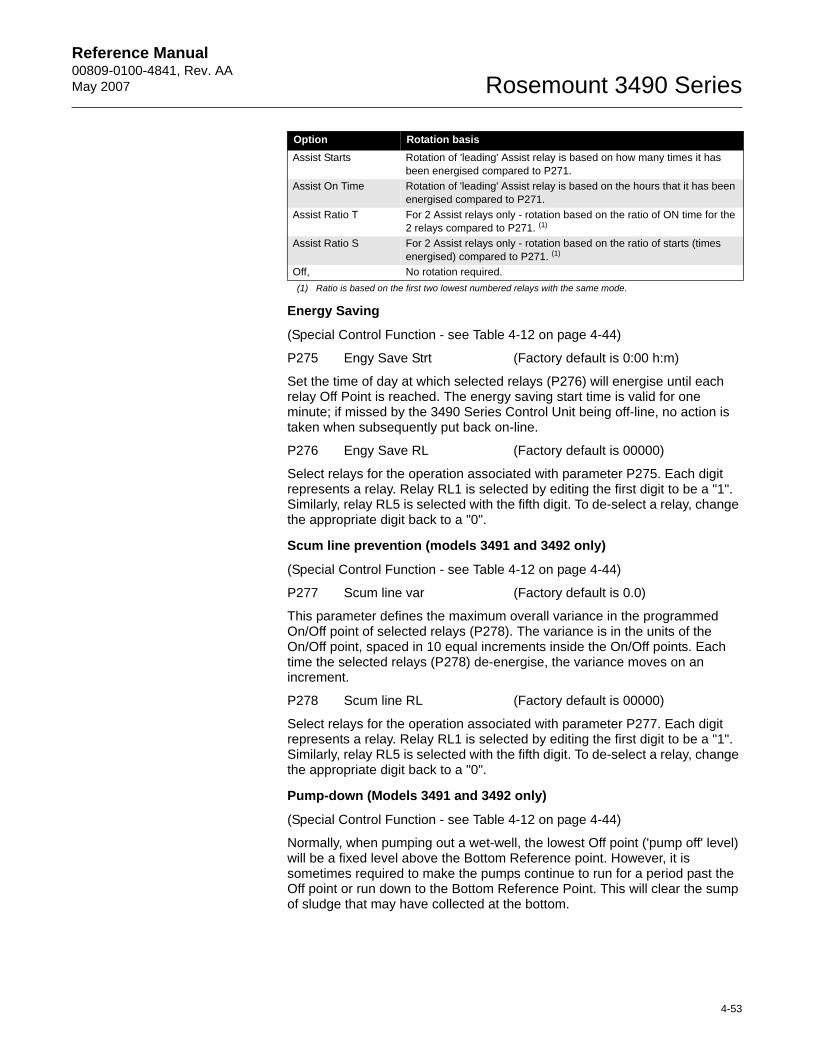
Reference Manual 00809-0100-4841, Rev. AA May 2007
4-53
Rosemount 3490 Series
Energy Saving
(Special Control Function - see Table 4-12 on page 4-44)
P275 Engy Save Strt (Factory default is 0:00 h:m)
Set the time of day at which selected relays (P276) will energise until each relay Off Point is reached. The energy saving start time is valid for one minute; if missed by the 3490 Series Control Unit being off-line, no action is taken when subsequently put back on-line.
P276 Engy Save RL (Factory default is 00000)
Select relays for the operation associated with parameter P275. Each digit represents a relay. Relay RL1 is selected by editing the first digit to be a "1". Similarly, relay RL5 is selected with the fifth digit. To de-select a relay, change the appropriate digit back to a "0".
Scum line prevention (models 3491 and 3492 only)
(Special Control Function - see Table 4-12 on page 4-44)
P277 Scum line var (Factory default is 0.0)
This parameter defines the maximum overall variance in the programmed On/Off point of selected relays (P278). The variance is in the units of the On/Off point, spaced in 10 equal increments inside the On/Off points. Each time the selected relays (P278) de-energise, the variance moves on an increment.
P278 Scum line RL (Factory default is 00000)
Select relays for the operation associated with parameter P277. Each digit represents a relay. Relay RL1 is selected by editing the first digit to be a "1". Similarly, relay RL5 is selected with the fifth digit. To de-select a relay, change the appropriate digit back to a "0".
Pump-down (Models 3491 and 3492 only)
(Special Control Function - see Table 4-12 on page 4-44)
Normally, when pumping out a wet-well, the lowest Off point ('pump off' level) will be a fixed level above the Bottom Reference point. However, it is sometimes required to make the pumps continue to run for a period past the Off point or run down to the Bottom Reference Point. This will clear the sump of sludge that may have collected at the bottom.
Assist Starts Rotation of 'leading' Assist relay is based on how many times it has been energised compared to P271.
Assist On Time Rotation of 'leading' Assist relay is based on the hours that it has been energised compared to P271.
Assist Ratio T For 2 Assist relays only - rotation based on the ratio of ON time for the 2 relays compared to P271. (1)
Assist Ratio S For 2 Assist relays only - rotation based on the ratio of starts (times energised) compared to P271. (1)
Off, No rotation required.(1) Ratio is based on the first two lowest numbered relays with the same mode.
Option Rotation basis
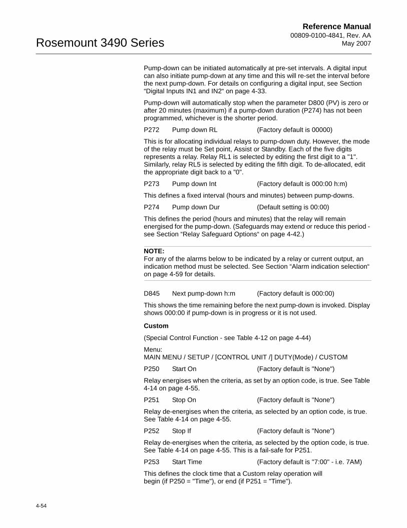
Reference Manual00809-0100-4841, Rev. AA
May 2007Rosemount 3490 Series
4-54
Pump-down can be initiated automatically at pre-set intervals. A digital input can also initiate pump-down at any time and this will re-set the interval before the next pump-down. For details on configuring a digital input, see Section “Digital Inputs IN1 and IN2“ on page 4-33.
Pump-down will automatically stop when the parameter D800 (PV) is zero or after 20 minutes (maximum) if a pump-down duration (P274) has not been programmed, whichever is the shorter period.
P272 Pump down RL (Factory default is 00000)
This is for allocating individual relays to pump-down duty. However, the mode of the relay must be Set point, Assist or Standby. Each of the five digits represents a relay. Relay RL1 is selected by editing the first digit to a "1". Similarly, relay RL5 is selected by editing the fifth digit. To de-allocated, edit the appropriate digit back to a "0".
P273 Pump down Int (Factory default is 000:00 h:m)
This defines a fixed interval (hours and minutes) between pump-downs.
P274 Pump down Dur (Default setting is 00:00)
This defines the period (hours and minutes) that the relay will remain energised for the pump-down. (Safeguards may extend or reduce this period - see Section “Relay Safeguard Options“ on page 4-42.)
NOTE:For any of the alarms below to be indicated by a relay or current output, an indication method must be selected. See Section “Alarm indication selection“ on page 4-59 for details.
D845 Next pump-down h:m (Factory default is 000:00)
This shows the time remaining before the next pump-down is invoked. Display shows 000:00 if pump-down is in progress or it is not used.
Custom
(Special Control Function - see Table 4-12 on page 4-44)
Menu:MAIN MENU / SETUP / [CONTROL UNIT /] DUTY(Mode) / CUSTOM
P250 Start On (Factory default is "None")
Relay energises when the criteria, as set by an option code, is true. See Table 4-14 on page 4-55.
P251 Stop On (Factory default is "None")
Relay de-energises when the criteria, as selected by an option code, is true. See Table 4-14 on page 4-55.
P252 Stop If (Factory default is "None")
Relay de-energises when the criteria, as selected by the option code, is true. See Table 4-14 on page 4-55. This is a fail-safe for P251.
P253 Start Time (Factory default is "7:00" - i.e. 7AM)
This defines the clock time that a Custom relay operation will begin (if P250 = "Time"), or end (if P251 = "Time").
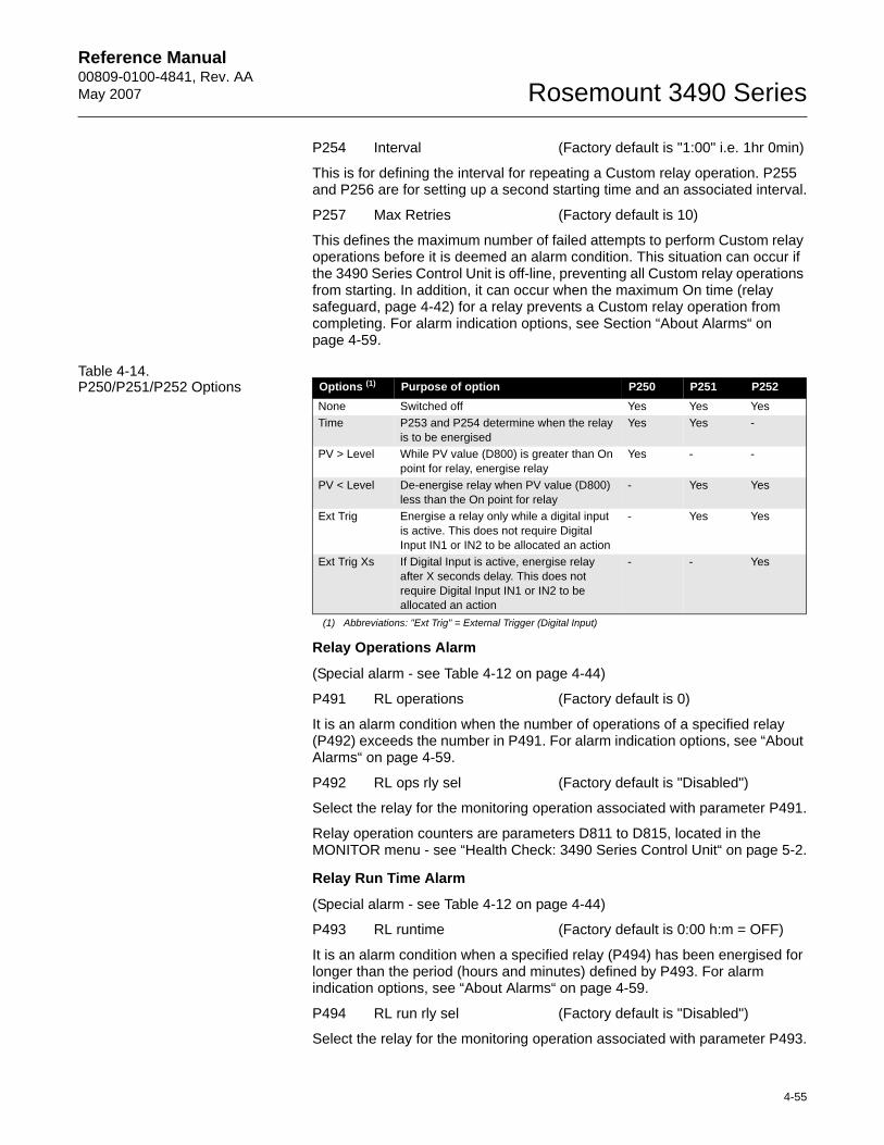
Reference Manual 00809-0100-4841, Rev. AA May 2007
4-55
Rosemount 3490 Series
P254 Interval (Factory default is "1:00" i.e. 1hr 0min)
This is for defining the interval for repeating a Custom relay operation. P255 and P256 are for setting up a second starting time and an associated interval.
P257 Max Retries (Factory default is 10)
This defines the maximum number of failed attempts to perform Custom relay operations before it is deemed an alarm condition. This situation can occur if the 3490 Series Control Unit is off-line, preventing all Custom relay operations from starting. In addition, it can occur when the maximum On time (relay safeguard, page 4-42) for a relay prevents a Custom relay operation from completing. For alarm indication options, see Section “About Alarms“ on page 4-59.
Table 4-14. P250/P251/P252 Options
Relay Operations Alarm
(Special alarm - see Table 4-12 on page 4-44)
P491 RL operations (Factory default is 0)
It is an alarm condition when the number of operations of a specified relay (P492) exceeds the number in P491. For alarm indication options, see “About Alarms“ on page 4-59.
P492 RL ops rly sel (Factory default is "Disabled")
Select the relay for the monitoring operation associated with parameter P491.
Relay operation counters are parameters D811 to D815, located in the MONITOR menu - see “Health Check: 3490 Series Control Unit“ on page 5-2.
Relay Run Time Alarm
(Special alarm - see Table 4-12 on page 4-44)
P493 RL runtime (Factory default is 0:00 h:m = OFF)
It is an alarm condition when a specified relay (P494) has been energised for longer than the period (hours and minutes) defined by P493. For alarm indication options, see “About Alarms“ on page 4-59.
P494 RL run rly sel (Factory default is "Disabled")
Select the relay for the monitoring operation associated with parameter P493.
Options (1)
(1) Abbreviations: "Ext Trig" = External Trigger (Digital Input)
Purpose of option P250 P251 P252None Switched off Yes Yes YesTime P253 and P254 determine when the relay
is to be energisedYes Yes -
PV > Level While PV value (D800) is greater than On point for relay, energise relay
Yes - -
PV < Level De-energise relay when PV value (D800) less than the On point for relay
- Yes Yes
Ext Trig Energise a relay only while a digital input is active. This does not require Digital Input IN1 or IN2 to be allocated an action
- Yes Yes
Ext Trig Xs If Digital Input is active, energise relay after X seconds delay. This does not require Digital Input IN1 or IN2 to be allocated an action
- - Yes
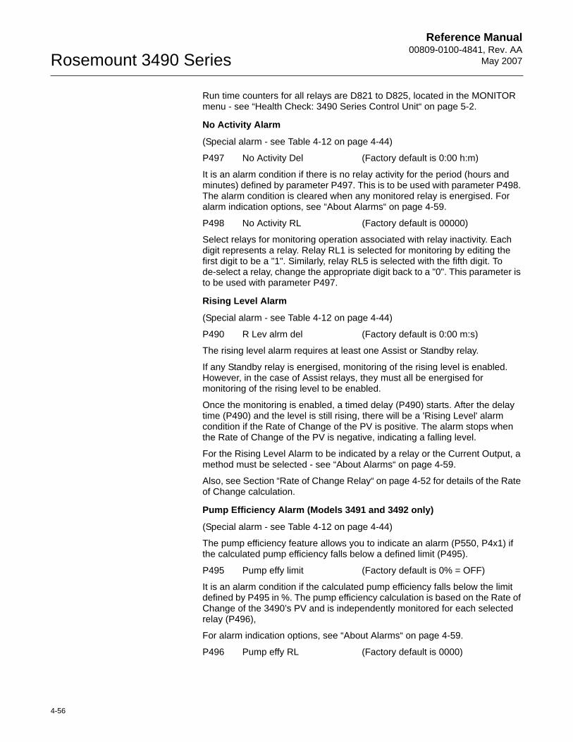
Reference Manual00809-0100-4841, Rev. AA
May 2007Rosemount 3490 Series
4-56
Run time counters for all relays are D821 to D825, located in the MONITOR menu - see “Health Check: 3490 Series Control Unit“ on page 5-2.
No Activity Alarm
(Special alarm - see Table 4-12 on page 4-44)
P497 No Activity Del (Factory default is 0:00 h:m)
It is an alarm condition if there is no relay activity for the period (hours and minutes) defined by parameter P497. This is to be used with parameter P498. The alarm condition is cleared when any monitored relay is energised. For alarm indication options, see “About Alarms“ on page 4-59.
P498 No Activity RL (Factory default is 00000)
Select relays for monitoring operation associated with relay inactivity. Each digit represents a relay. Relay RL1 is selected for monitoring by editing the first digit to be a "1". Similarly, relay RL5 is selected with the fifth digit. To de-select a relay, change the appropriate digit back to a "0". This parameter is to be used with parameter P497.
Rising Level Alarm
(Special alarm - see Table 4-12 on page 4-44)
P490 R Lev alrm del (Factory default is 0:00 m:s)
The rising level alarm requires at least one Assist or Standby relay.
If any Standby relay is energised, monitoring of the rising level is enabled. However, in the case of Assist relays, they must all be energised for monitoring of the rising level to be enabled.
Once the monitoring is enabled, a timed delay (P490) starts. After the delay time (P490) and the level is still rising, there will be a 'Rising Level' alarm condition if the Rate of Change of the PV is positive. The alarm stops when the Rate of Change of the PV is negative, indicating a falling level.
For the Rising Level Alarm to be indicated by a relay or the Current Output, a method must be selected - see “About Alarms“ on page 4-59.
Also, see Section “Rate of Change Relay“ on page 4-52 for details of the Rate of Change calculation.
Pump Efficiency Alarm (Models 3491 and 3492 only)
(Special alarm - see Table 4-12 on page 4-44)
The pump efficiency feature allows you to indicate an alarm (P550, P4x1) if the calculated pump efficiency falls below a defined limit (P495).
P495 Pump effy limit (Factory default is 0% = OFF)
It is an alarm condition if the calculated pump efficiency falls below the limit defined by P495 in %. The pump efficiency calculation is based on the Rate of Change of the 3490’s PV and is independently monitored for each selected relay (P496),
For alarm indication options, see “About Alarms“ on page 4-59.
P496 Pump effy RL (Factory default is 0000)
Reference Manual 00809-0100-4841, Rev. AA May 2007
4-57
Rosemount 3490 Series
Select relays for monitoring operation associated with the pump efficiency limit. Each digit represents a relay. Relay RL1 is selected by editing the first digit to be a "1". Similarly, relay RL4 is selected with the fourth digit. (Relay RL5 does not support this feature.) To de-select a relay, change the appropriate digit to a "0". This parameter is to be used with parameter P495.
Pump efficiency values for relays are saved in D861 to D864, located in the MONITOR menu - see “Health Check: 3490 Series Control Unit“ on page 5-2.
Pump Efficiency Explanation
Pump efficiency (PE) is calculated based upon the rate of Change (RoC) of the MCU PV whilst any single pump is on.
The pump efficiency value, (D86*, where “*” is the number of the associated pump relay 1 - 4) is calculated only whilst that pump is operating. The calculations will pause when the pump stops or when other pumps start. Calculations re-start when the relevant pump starts again.
To calculate the pump efficiency, the 3490 Series Control Unit assumes that liquid continues to enter the well or tank during pump operation at the rate just prior to the pump starting.
The 3490 Series Control Unit continuously calculates the RoC of the PV, making a new measurement every 5 seconds, as described in Section “Rate of Change Relay“ on page 4-52. Once the selected pump starts, the 3490 Series Control Unit will monitor and record the change in RoC over the next 5 measurements. Over the next 9 pump starts, a further 9 change of RoC values are stored such that the 3490 can then calculate an average value in change of RoC. This average value, "RoC100" is then taken as being equivalent to the pump operating at 100% efficiency. A value of 100% is then stored in D86*.
Each pump start, and change in RoC thereafter, is used in a rolling average calculation for a new average value in change of RoC, RoCnew, which is then compared to the previous value "RoC100" and a new PE percentage value calculated using:
PE % = (RoCnew / RoC100) * 100
If the resulting percentage is greater than 100%, then the RoC100 is updated to the new value and the PE re-stated as 100% based on this new value.
If the resulting percentage is less than 100%, then the PE is calculated as above and stored in D86*
If the PE is below the limit set (P495), the PE alarm condition is true - to indicate an alarm by relay or current output, a method must be selected - refer to “About Alarms“ on page 4-59.
NOTE:The alarm condition is automatically cleared if the calculated PE rises above the limit (P495) by 5% or more.
Reference Manual00809-0100-4841, Rev. AA
May 2007Rosemount 3490 Series
4-58
Pumped Volume Totalising
(Totaliser Option - see Table 4-12 on page 4-44)
This function may be used to determine the total throughput of a well.
NOTE:The "Totaliser" Wizard can be used to set-up Pumped Volume Totalising - see Section “Totaliser Wizard“ on page 4-66.
The 3490 Series Control Unit monitors what goes into the well when no pumps are running. It calculates the Rate of Change (RoC) of PV every 5 seconds and then converts it to a Rate of Change per minute for displaying as parameter D809.
When a pump is turned on, the 3490 Series Control Unit assumes that the rate of inflow remains the same as it was just before starting the pumps. The RoC value (D809) is frozen whilst the pumps are on, i.e. when any Assist or Standby relay is energised.
In order to totalise pumped volume, the PV value (D800) must be in volume units so that the RoC value is in volume units per minute. The 3490 Series Control Unit integrates this volume every second and increments the totaliser for every integer unit.
Therefore, if the RoC value (D809) is 12m3 per minute and the total factor (P530) is set to 1.0 (m3), the Totaliser Count (D828) will increment every5 seconds (1/12th of a minute = 5 seconds).
Menu: MAIN MENU / SETUP / [CONTROL UNIT /] OUTPUT / TOTALISER
P530 Total factor (Factor default is 0.0)
One count is added to the Totaliser Count (D828) for a quantity of liquid as defined by this parameter.
P531 Total units (Factory default is "None")
Pumped Volume Totalising is selected by the totaliser units (P531) being set to "PVol". (This parameter defines the display units for parameter D828).
NOTE:For other associated parameters, see “About Totalising On Model 3491“ on page 4-62.
Reference Manual 00809-0100-4841, Rev. AA May 2007
4-59
Rosemount 3490 Series
About Alarms Alarms
The 3490 Series Control Unit can detect the following alarm conditions:• PV value out-of-limits.• Current Output saturated
(Standard: ≤ 3.9mA or ≥ 20.8mA, NAMUR NE43: ≤ 3.8mA or ≥ 20.5mA)• Logging memory filling (model 3493 only).• Logging memory full (model 3493 only).• Digital input is configured to force an alarm when active.• Maximum number of failed Custom relay operation attempts.• Current Input saturated.• Rising liquid level.• Relay operation count limit exceeded.• Relay run time limit exceeded.• Low pump efficiency (models 3491 and 3492 only).• Relay inactivity.
Parameter D830 shows a list of active alarms. In addition, alarms are indicated by means of Relays, Current Output, or both (see below).Table 4-15 on page 4-61 has a summary of reporting methods for alarms.
Alarm indication selection
For each alarm listed in Section “Alarms“ on page 4-59, there is a dedicated parameter in the ALARM menu for selecting the method of indication for that alarm.
Menu: MAIN MENU / SETUP / [CONTROL UNIT /] OUTPUT / ALARM
P540 PV Over Limits (Factory default is "None")
Select the indication method for the alarm condition that occurs if the PV value is outside pre-set limits.
See also Section “PV limits Relay“ on page 4-52.
P541 mA Out Sat (Factory default is "None")
Select the indication method for the alarm condition that occurs if theCurrent Output is ≤ 3.8mA or ≥ 20.5mA
P542 Log mem filling (Factory default is "None")
Select the indication method for the alarm condition that occurs if the available logging memory is low. See also Section “P593: Low Memory Alarm“ on page 4-34.
P543 Digital Input (Factory default is "None")
Select the indication method for the alarm condition that only occurs if a digital input is configured to force this alarm and that digital input is active - see Section “Digital Inputs IN1 and IN2“ on page 4-33.
P544 Max retries (Factory default is "None")
Select the indication method for the alarm condition that only occurs if a Custom relay operation is unable to complete as specified, even after a pre-set number of attempts (P257). See also Section “Custom“ on page 4-54.
Reference Manual00809-0100-4841, Rev. AA
May 2007Rosemount 3490 Series
4-60
P545 mA In Sat (Factory default is "None")
Select the indication method for the alarm condition that occurs if the Current Input is ≤ 3.7mA or ≥ 20.75mA.
P547 Rising Level (Factory default is "None")
Select the indication method for the alarm condition that occurs if the PV value is increasing (or decreasing) at a rate that exceeds is a programmed threshold. See also Section “Rising Level Alarm“ on page 4-56.
P548 RL Operations (Factory default is "None")
Select the indication method for the alarm condition that occurs if a relay operation counter exceeds a pre-set limit.
See also Section “Relay Operations Alarm“ on page 4-55.
P549 RL runtime (Factory default is "None")
Select the indication method for the alarm condition that occurs if a relay is energised for longer than a pre-set period.
See also Section “Relay Run Time Alarm“ on page 4-55.
P550 Pump efficiency (Factory default is "None")
On models 3491/3492 only. Select the indication method for the alarm condition that occurs if the calculated pump efficiency falls below a pre-set limit. See also Section “Pump Efficiency Alarm (Models 3491 and 3492 only)“ on page 4-56.
P531 No activity (Factory default is "None")
Select the indication method for the alarm condition that occurs if any selected relay is de-energised for longer than a pre-set period. See also Section “No Activity Alarm“ on page 4-56.
Options for parameters P540 to P551 are:• None - if the alarm will not to be indicated • Both - alarm indicated by Relay Output (see below) and Current Output• Current - alarm will be indicated by the Current Output• Relay - alarm will be indicated by Relay Output (see below)
If the indication method for a particular alarm is a Relay Output (e.g. RL1), the mode of a relay (e.g. P411) must first be set to the "Alarm" option. After this is set-up, all 'Alarm duty' relays are energised while the alarm condition exists. When there is no alarm condition (or the alarm condition has ceased), 'Alarm duty' relays are de-energised.
More than one Relay Output can be allocated to alarm duty, if required. On the primary display, the relay status icon shows an "A" if it is allocated to alarm duty and the relay is energised.
(For information on relays, see also “Relays“ on page 4-39.)
If the indication method is the Current Output, parameter P402 is used to determine how the Current Output will indicate an alarm condition - see Section “Current Output“ on page 4-38 for alarm action options.
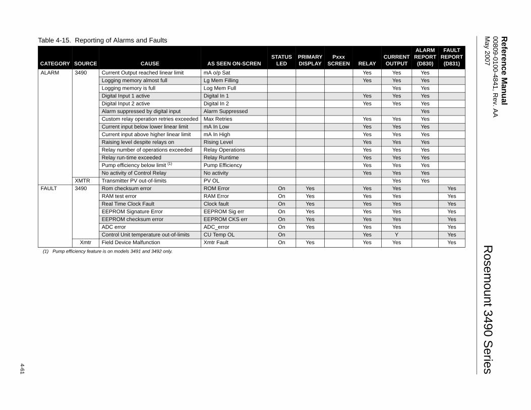
Reference M
anual 00809-0100-4841, R
ev. AA
M
ay 2007
4-61
Rosem
ount 3490 Series
Table 4-15. Reporting of Alarms and Faults
CATEGORY SOURCE CAUSE AS SEEN ON-SCRENSTATUS
LEDPRIMARY DISPLAY
Pxxx SCREEN RELAY
CURRENT OUTPUT
ALARM REPORT
(D830)
FAULT REPORT
(D831)ALARM 3490 Current Output reached linear limit mA o/p Sat Yes Yes Yes
Logging memory almost full Lg Mem Filling Yes Yes YesLogging memory is full Log Mem Full Yes YesDigital Input 1 active Digital In 1 Yes Yes YesDigital Input 2 active Digital In 2 Yes Yes YesAlarm suppressed by digital input Alarm Suppressed YesCustom relay operation retries exceeded Max Retries Yes Yes YesCurrent input below lower linear limit mA In Low Yes Yes YesCurrent input above higher linear limit mA In High Yes Yes YesRaising level despite relays on Rising Level Yes Yes YesRelay number of operations exceeded Relay Operations Yes Yes YesRelay run-time exceeded Relay Runtime Yes Yes YesPump efficiency below limit (1)
(1) Pump efficiency feature is on models 3491 and 3492 only.
Pump Efficiency Yes Yes YesNo activity of Control Relay No activity Yes Yes Yes
XMTR Transmitter PV out-of-limits PV OL Yes YesFAULT 3490 Rom checksum error ROM Error On Yes Yes Yes Yes
RAM test error RAM Error On Yes Yes Yes YesReal Time Clock Fault Clock fault On Yes Yes Yes YesEEPROM Signature Error EEPROM Sig err On Yes Yes Yes YesEEPROM checksum error EEPROM CKS err On Yes Yes Yes YesADC error ADC_error On Yes Yes Yes YesControl Unit temperature out-of-limits CU Temp OL On Yes Y Yes
Xmtr Field Device Malfunction Xmtr Fault On Yes Yes Yes Yes
Reference Manual00809-0100-4841, Rev. AA
May 2007Rosemount 3490 Series
4-62
About Totalising On Model 3491
Totaliser (Cumulative totalised flow) on Model 3491
Model 3491 has one internal, 8-digit, totaliser, which is updated several times per second. A Totaliser relay can be configured to output a pulse for each increment to the Totaliser Count parameter. For information on setting up a relay to output 'totaliser' pulses, see “Relays“ on page 4-39.
NOTE:For totalising examples, see “Totalising examples“ on page 4-67.
NOTE:Totalisers are set-up to operate with an input of PV in units/second. If the PV value is a volumetric flow rate (e.g. m3/hour), the totaliser can accumulate this volume of flow, therefore giving the total volume throughput.
Menu: MAIN MENU / SETUP / [CONTROL UNIT /] OUTPUT / TOTALISER
P530 Total factor (Factor default is 0.0)
One count is added to the Totaliser Count (D828) for a quantity of liquid as defined by this parameter. The display units for D828 is defined by P531.
P531 Total units (Factory default is "None")
This parameter defines the units for the Totaliser Count (D828).
When using units of gal (US gallons), an 8-digit totaliser increments rapidly and rolls over too frequently. To help with this, alternative totaliser units of galx10, galx100, and galx1000 are available for selection. When these special units are selected after selecting gal units, the totaliser factor (P530) is automatically re-scaled by x10, x100, or x1000 depending on the selection.
NOTE:If requiring Pumped Volume Totalising, see page 4-58.
P534 Pulse Width (Factory default is "100ms")
A Totaliser relay is energised for a programmed duration (P534) each time the Totaliser Count (D828) is incriminated. Parameter P534 controls the 'On' time and 'Off' time - i.e. the pulse width - and may be a value of between 10ms and 2.5s, changeable in steps of 10ms.
The rate at which the unit can output a totaliser pulse is entirely dependent on the pulse width. Parameter P534 also determines the width of a pulse that is output by a Sampler relay (see “Sampler Relay Output“ on page 4-66).
Menu:MAIN MENU / MONITOR / [CONTROL UNIT /] READINGS / TOTALISER
D828 Totaliser
This parameter displays the Totaliser Count. To add this to the primary display, see “Primary Display Options“ on page 4-71.
Resetting the totaliser On Model 3491
To re-set a totaliser to zero, display the Totaliser Count parameter e.g. D828, and then press the button corresponding to "Reset" on display line 4.
Reference Manual 00809-0100-4841, Rev. AA May 2007
4-63
Rosemount 3490 Series
About Totalising on Model 3492
Model 3492 has two independent, internal, 8-digit, totalisers - Totaliser 1 and Totaliser 2 - which are updated several times per second.
Totaliser 1 is dedicated to totalising the PV value (D800). When the PV value is a volumetric flow rate (e.g. m3/hour), the totaliser can accumulate this flow, therefore giving the total volume throughput.
Totaliser 2 operates in the same way as Totaliser 1, but counts the parameter selected by P536. Parameter P536 offers a choice of PV, SV, TV, and FV.
A Totaliser relay can be configured to output a pulse for each increment (by one) to the Totaliser 1 or 2 Count parameter. For information on setting up a relay to output 'totaliser' pulses, see Sections “Relays“ on page 4-39 and “Totalising examples“ on page 4-67.
NOTE:For totalising examples, see “Totalising examples“ on page 4-67.
Menu: MAIN MENU / SETUP / [CONTROL UNIT /] OUTPUT / TOTALISER
P530 Total 1 factor (Factor default is 0.0)
One count is added to the Totaliser Count (D828) for a quantity of flow as defined by this parameter. The unit of measurement for D828 is defined by parameter P531.
P531 Total 1 units (Factory default is "None")
This parameter defines the units for the Totaliser 1 Count (D828)
When using units of gal (US gallons), an 8-digit totaliser increments rapidly and rolls over too frequently. To help with this, alternative totaliser units of galx10, galx100, and galx1000 are available for selection. When these special units are selected after selecting gal units, the totaliser factor (P530) is automatically re-scaled by x10, x100, or x1000 depending on the selection.
NOTE:If requiring Pumped Volume Totalising, see page 4-58.
P532 Total 2 factor (Factor default is 0.0)
One count is added to the Totaliser 2 Count (D829) for a quantity of liquid as defined by this parameter. The units for D829 is defined by P533.
P533 Total 2 units (Factory default is "None")
This parameter defines the units for the Totaliser 2 Count (D829).
When using units of gal (US gallons), an 8-digit totaliser increments rapidly and rolls over too frequently. To help with this, alternative totaliser units of galx10, galx100, and galx1000 are available for selection. When these special units are selected after selecting gal units, the totaliser factor (P530) is automatically re-scaled by x10, x100, or x1000 depending on the selection.
NOTE:If requiring Pumped Volume Totalising, see page 4-58.
Reference Manual00809-0100-4841, Rev. AA
May 2007Rosemount 3490 Series
4-64
P534 Pulse Width (Factory default is "100ms")
A Totaliser relay is energised for a programmed duration (P534) each time a Totaliser Count (D828/D829) is incriminated. Parameter P534 controls the 'On' time and 'Off' time - i.e. the pulse width - and may be a value of between 10ms and 2.5s, changeable in steps of 10ms.
The rate at which the unit can output a totaliser pulse is entirely dependent on the pulse width. Parameter P534 also determines the width of a pulse that is output by a Sampler relay - see “Sampler Relay Output“ on page 4-66.
P536 Totaliser 2 Source (Factory default is "None")
If requiring Totaliser 2, select a parameter to be totalised.Menu: <MAIN MENU>/<MONITOR>/[<CONTROL UNIT>/] <READINGS>/ <TOTALISER>
D828 Totaliser 1
This parameter displays the Totaliser 1 Count. To add this to the primary display, see “Primary Display Options“ on page 4-71.
D829 Totaliser 2
This parameter displays the Totaliser 2 Count. To add this to the primary display, see “Primary Display Options“ on page 4-71.
Resetting the totaliser
To re-set a totaliser to zero, display the Totaliser Count parameter e.g. D828, and then press the button corresponding to "Reset" on display line 4.
About Totalising on Model 3493
Model 3493 has two totalisers:
Totaliser 1 (Cumulative totalised flow) on Model 3493
This is an 8-digit totaliser showing cumulative totalised flow through a flow structure. It can only be re-set manually.
Menu: MAIN MENU / SETUP / [CONTROL UNIT /] OUTPUT / TOTALISER
P530 Total 1 Factor (Factor default is 0.0)
One count is added to the Totaliser Count (D828) for a quantity of liquid as defined by this parameter. The display units for D828 is defined by P531.
P531 Total 1 Units (Factory default is "None")
This parameter defines the units for the Totaliser Count (D828).
When using units of gal (US gallons), an 8-digit totaliser increments rapidly and rolls over too frequently. To help with this, alternative totaliser units of galx10, galx100, and galx1000 are available for selection. When these special units are selected after selecting gal units, the totaliser factor (P530) is automatically re-scaled by x10, x100, or x1000 depending on the selection
P534 Pulse Width (Factory default is "100ms")
A Totaliser relay is energised for a programmed duration (P534) each time the Totaliser Count (D828 / D829) is incremented. Parameter P534 controls the 'On' time and 'Off' time - i.e. pulse width - and may be a value of between 10ms and 2500ms (0.01 to 2.5 seconds), changeable in steps of 10ms.
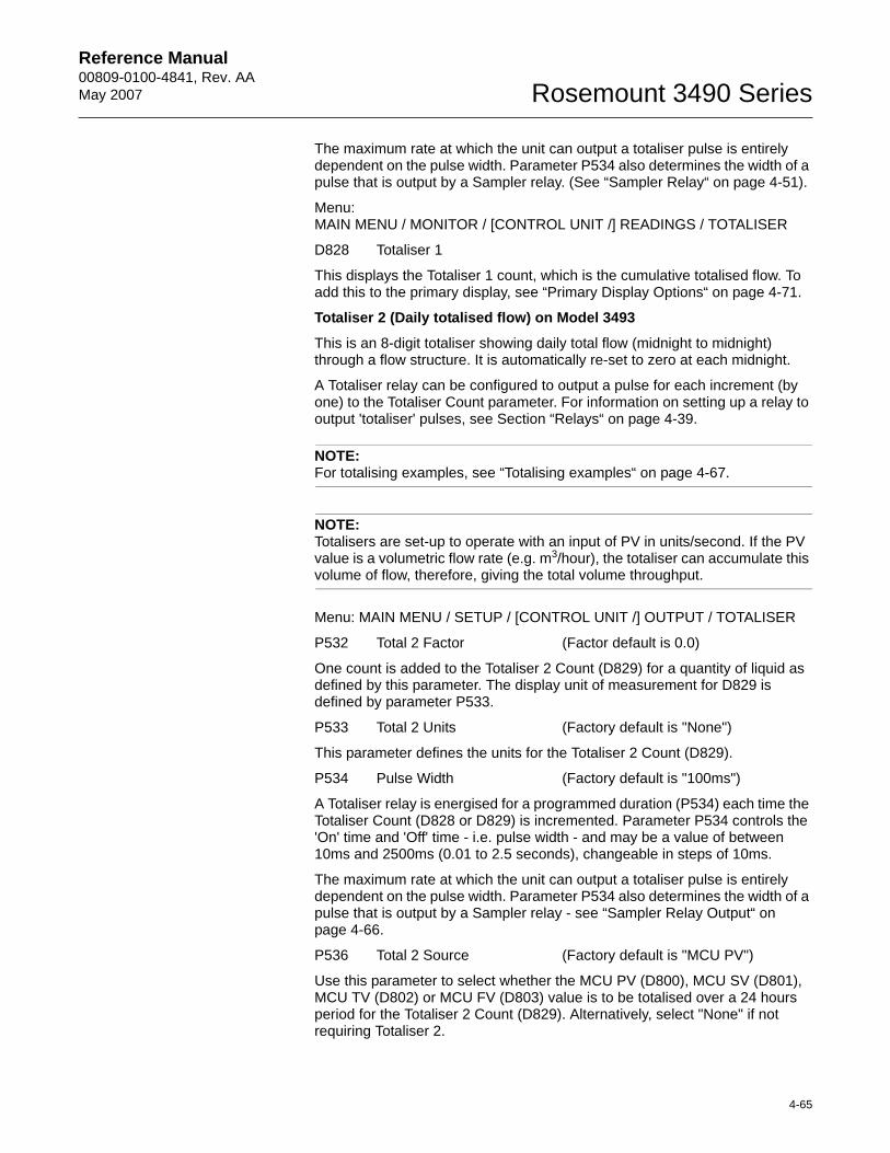
Reference Manual 00809-0100-4841, Rev. AA May 2007
4-65
Rosemount 3490 Series
The maximum rate at which the unit can output a totaliser pulse is entirely dependent on the pulse width. Parameter P534 also determines the width of a pulse that is output by a Sampler relay. (See “Sampler Relay“ on page 4-51).
Menu:MAIN MENU / MONITOR / [CONTROL UNIT /] READINGS / TOTALISER
D828 Totaliser 1
This displays the Totaliser 1 count, which is the cumulative totalised flow. To add this to the primary display, see “Primary Display Options“ on page 4-71.
Totaliser 2 (Daily totalised flow) on Model 3493
This is an 8-digit totaliser showing daily total flow (midnight to midnight) through a flow structure. It is automatically re-set to zero at each midnight.
A Totaliser relay can be configured to output a pulse for each increment (by one) to the Totaliser Count parameter. For information on setting up a relay to output 'totaliser' pulses, see Section “Relays“ on page 4-39.
NOTE:For totalising examples, see “Totalising examples“ on page 4-67.
NOTE:Totalisers are set-up to operate with an input of PV in units/second. If the PV value is a volumetric flow rate (e.g. m3/hour), the totaliser can accumulate this volume of flow, therefore, giving the total volume throughput.
Menu: MAIN MENU / SETUP / [CONTROL UNIT /] OUTPUT / TOTALISER
P532 Total 2 Factor (Factor default is 0.0)
One count is added to the Totaliser 2 Count (D829) for a quantity of liquid as defined by this parameter. The display unit of measurement for D829 is defined by parameter P533.
P533 Total 2 Units (Factory default is "None")
This parameter defines the units for the Totaliser 2 Count (D829).
P534 Pulse Width (Factory default is "100ms")
A Totaliser relay is energised for a programmed duration (P534) each time the Totaliser Count (D828 or D829) is incremented. Parameter P534 controls the 'On' time and 'Off' time - i.e. pulse width - and may be a value of between 10ms and 2500ms (0.01 to 2.5 seconds), changeable in steps of 10ms.
The maximum rate at which the unit can output a totaliser pulse is entirely dependent on the pulse width. Parameter P534 also determines the width of a pulse that is output by a Sampler relay - see “Sampler Relay Output“ on page 4-66.
P536 Total 2 Source (Factory default is "MCU PV")
Use this parameter to select whether the MCU PV (D800), MCU SV (D801), MCU TV (D802) or MCU FV (D803) value is to be totalised over a 24 hours period for the Totaliser 2 Count (D829). Alternatively, select "None" if not requiring Totaliser 2.
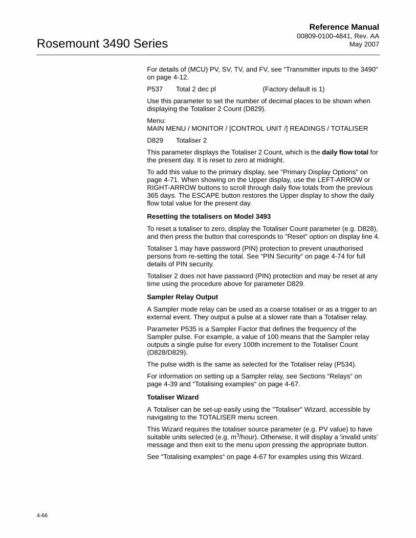
Reference Manual00809-0100-4841, Rev. AA
May 2007Rosemount 3490 Series
4-66
For details of (MCU) PV, SV, TV, and FV, see “Transmitter inputs to the 3490“ on page 4-12.
P537 Total 2 dec pl (Factory default is 1)
Use this parameter to set the number of decimal places to be shown when displaying the Totaliser 2 Count (D829).
Menu:MAIN MENU / MONITOR / [CONTROL UNIT /] READINGS / TOTALISER
D829 Totaliser 2
This parameter displays the Totaliser 2 Count, which is the daily flow total for the present day. It is reset to zero at midnight.
To add this value to the primary display, see “Primary Display Options“ on page 4-71. When showing on the Upper display, use the LEFT-ARROW or RIGHT-ARROW buttons to scroll through daily flow totals from the previous 365 days. The ESCAPE button restores the Upper display to show the daily flow total value for the present day.
Resetting the totalisers on Model 3493
To reset a totaliser to zero, display the Totaliser Count parameter (e.g. D828), and then press the button that corresponds to "Reset" option on display line 4.
Totaliser 1 may have password (PIN) protection to prevent unauthorised persons from re-setting the total. See “PIN Security“ on page 4-74 for full details of PIN security.
Totaliser 2 does not have password (PIN) protection and may be reset at any time using the procedure above for parameter D829.
Sampler Relay Output
A Sampler mode relay can be used as a coarse totaliser or as a trigger to an external event. They output a pulse at a slower rate than a Totaliser relay.
Parameter P535 is a Sampler Factor that defines the frequency of the Sampler pulse. For example, a value of 100 means that the Sampler relay outputs a single pulse for every 100th increment to the Totaliser Count (D828/D829).
The pulse width is the same as selected for the Totaliser relay (P534).
For information on setting up a Sampler relay, see Sections “Relays“ on page 4-39 and “Totalising examples“ on page 4-67.
Totaliser Wizard
A Totaliser can be set-up easily using the "Totaliser" Wizard, accessible by navigating to the TOTALISER menu screen.
This Wizard requires the totaliser source parameter (e.g. PV value) to have suitable units selected (e.g. m3/hour). Otherwise, it will display a 'invalid units' message and then exit to the menu upon pressing the appropriate button.
See “Totalising examples“ on page 4-67 for examples using this Wizard.
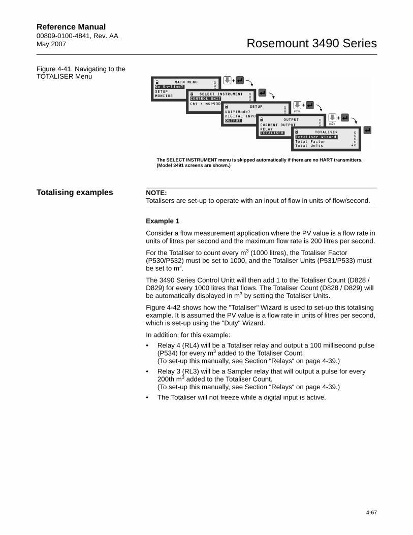
Reference Manual 00809-0100-4841, Rev. AA May 2007
4-67
Rosemount 3490 Series
Figure 4-41. Navigating to the TOTALISER Menu
Totalising examples NOTE:Totalisers are set-up to operate with an input of flow in units of flow/second.
Example 1
Consider a flow measurement application where the PV value is a flow rate in units of litres per second and the maximum flow rate is 200 litres per second.
For the Totaliser to count every m3 (1000 litres), the Totaliser Factor (P530/P532) must be set to 1000, and the Totaliser Units (P531/P533) must be set to m3.
The 3490 Series Control Unitt will then add 1 to the Totaliser Count (D828 / D829) for every 1000 litres that flows. The Totaliser Count (D828 / D829) will be automatically displayed in m3 by setting the Totaliser Units.
Figure 4-42 shows how the "Totaliser" Wizard is used to set-up this totalising example. It is assumed the PV value is a flow rate in units of litres per second, which is set-up using the "Duty" Wizard.
In addition, for this example:• Relay 4 (RL4) will be a Totaliser relay and output a 100 millisecond pulse
(P534) for every m3 added to the Totaliser Count. (To set-up this manually, see Section “Relays“ on page 4-39.)
• Relay 3 (RL3) will be a Sampler relay that will output a pulse for every 200th m3 added to the Totaliser Count. (To set-up this manually, see Section “Relays“ on page 4-39.)
• The Totaliser will not freeze while a digital input is active.
The SELECT INSTRUMENT menu is skipped automatically if there are no HART transmitters. (Model 3491 screens are shown.)
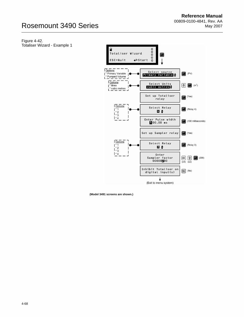
Reference Manual00809-0100-4841, Rev. AA
May 2007Rosemount 3490 Series
4-68
Figure 4-42. Totaliser Wizard - Example 1
(Model 3491 screens are shown.)
Reference Manual 00809-0100-4841, Rev. AA May 2007
4-69
Rosemount 3490 Series
Example 2
Consider a flow measurement application where the PV value is a flow rate in units of cubic metres per hour (m3/hour).
As the totalisers are set-up to operate with an input of flow in units of flow/second, the input of m3/hour in this example must be scaled. This is achieved by multiplying the totaliser factor, 1.0 in this example, by 60 x 60 to get flow in units of flow/second.
For the Totaliser to count every 100 m3, the Totaliser Factor (P530/P532) must be set to 3600 (1 x 60 x 60) and the Totaliser Units (P531/P533) must be set to m3.
The 3490 Series Control Unit will then add 1 to the Totaliser Count (D828 / D829) for every 100 cubic metres that flows. The Totaliser Count will be automatically displayed in m3 by setting the Totaliser Units.
Figure 4-43 on page 4-70 shows how the "Totaliser" Wizard can be used to set-up this totalising example. It is assumed the PV value is a flow rate in units of cubic metres per hour, which can be set-up using the "Duty" Wizard.
In addition, for this example:• Relay 4 (RL4) will be a Totaliser relay and output a 200 millisecond pulse
(P534) for every 100 m3 added to the Totaliser Count. (To set-up this manually, see “Relays“ on page 4-39.)
• No Sampler relay is required.• The Totaliser will freeze immediately when any digital input is active i.e.
when the voltage-free contact is closed.(To set-up this manually, see “Digital Inputs IN1 and IN2“ on page 4-33.)
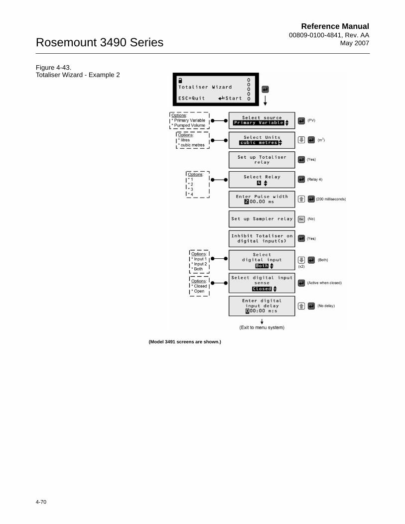
Reference Manual00809-0100-4841, Rev. AA
May 2007Rosemount 3490 Series
4-70
Figure 4-43. Totaliser Wizard - Example 2
(Model 3491 screens are shown.)
Reference Manual 00809-0100-4841, Rev. AA May 2007
4-71
Rosemount 3490 Series
Primary Display Options The factory default configuration of the primary display can be changed to show different graphic and text information.
Three areas of the primary display can be re-configured:• Upper display• Middle display• Lower display
In addition, the number of decimal places and the back light operation can be adjusted.
Menu: MAIN MENU / SETUP / [CONTROL UNIT /] OUTPUT / DISPLAY
P570 Display Upper (Factory default is "P731-Time")
Select from the multiple-choice list of parameters (see Table 4-16 on page 4-72). For example, you can display the Totaliser count when "D828-Totaliser" is selected. If it will fit, the clock time will also be displayed alongside the selected parameter.
P571 Display Middle (Factory default is "D800-PV")
Select from the multiple-choice list of parameters (see Table 4-16 on page 4-72). For example, you can display the (3490) SV value when "D801-SV" is selected.
P572 Display Lower (Factory default is "Bargraph")
(Bargraph represents the 4-20mA output)
Select from the multiple-choice list of parameters (see Table 4-16 on page 4-72). For example, you can display a user-defined message (P241) when the 'P241' option is selected.
P573 Decimal places (Factory default is 3)
Use this to adjust the number of decimal places. Range 0 to 5. Alternatively, select "Disabled" (Auto) for the 3490 Series Control Unit to automatically choose the number of decimal places for a displayed parameter value.
P574 Display size (Factory default is “Large”)
Use this to adjust whether the Primary Display shows the Large PV Display after a period of keypad inactivity, or remains showing the Full PV Display.
P575 Back light (Factory default is "On")
Select from "On" (always on), "Off" (always off) or "Auto" (goes on when using keypad; goes off after 5 minutes of inactivity).
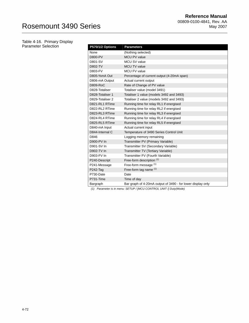
Reference Manual00809-0100-4841, Rev. AA
May 2007Rosemount 3490 Series
4-72
Table 4-16. Primary Display Parameter Selection P570/1/2 Options Parameters
None (Nothing selected)D800-PV MCU PV valueD801-SV MCU SV valueD802-TV MCU TV valueD803-FV MCU FV valueD805-%mA Out Percentage of current output (4-20mA span)D806-mA Output Actual current outputD809-RoC Rate of Change of PV valueD828-Totaliser Totaliser value (model 3491)D828-Totaliser 1 Totaliser 1 value (models 3492 and 3493)D829-Totaliser 2 Totaliser 2 value (models 3492 and 3493)D821-RL1 RTime Running time for relay RL1 if energisedD822-RL2 RTime Running time for relay RL2 if energisedD823-RL3 RTime Running time for relay RL3 if energisedD824-RL4 RTime Running time for relay RL4 if energisedD825-RL5 RTime Running time for relay RL5 if energisedD840-mA Input Actual current inputD844-Internal C Temperature of 3490 Series Control UnitD846 Logging memory remainingD900-PV In Transmitter PV (Primary Variable)D901-SV In Transmitter SV (Secondary Variable)D902-TV In Transmitter TV (Tertiary Variable)D903-FV In Transmitter FV (Fourth Variable)P240-Descript Free-form description (1)
(1) Parameter is in menu: SETUP / [MCU CONTROL UNIT /] Duty(Mode)
P241-Message Free-form message (1)
P242-Tag Free-form tag name (1)
P730-Date DateP731-Time Time of dayBargraph Bar graph of 4-20mA output of 3490 - for lower display only
Reference Manual 00809-0100-4841, Rev. AA May 2007
4-73
Rosemount 3490 Series
Serial Communications This section is applicable if an RS232 serial port of a communication device (e.g. PC) is connected to the RS232 terminals of the 3490 Series Control Unit or data download socket of the 3493. (For connections details, refer to Section 3: The plug/socket connectors are polarized to prevent inter-changeability and incorrect connection).
Menu:
MAIN MENU / SETUP / [CONTROL UNIT /] OUTPUT / SYSTEM / COMMS
P710 Address (Factory default is 0)
Leave this at the factory default setting.
P711 Interface
Choose between "Log download" (model 3493), "RS232 HART", or "None".
P712 Baud Rate (Factory default is "1200" or "9600)
This must be the same as set for the RS232 serial port of the communication device. Range is 1200 to 115200.
P713 Start Bits (Factory default is 1)
This must be the same as set for the RS232 serial port of the communication device. Range is 0 to 9.
P714 Data Bits (Factory default is 8)
This must be the same as set for the RS232 serial port of the communication device. Range is 0 to 9.
P715 Parity (Factory default is "Even")
This must be the same as set for the RS232 serial port of the communication device. Options are "Even", "Odd" or "None".
P716 Stop Bits (Factory default is 1)
This must be the same as set for the RS232 serial port of the communication device. Range is 0 to 9
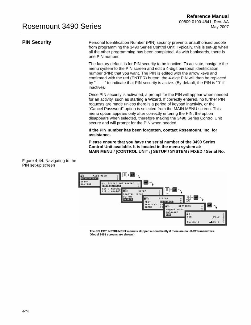
Reference Manual00809-0100-4841, Rev. AA
May 2007Rosemount 3490 Series
4-74
PIN Security Personal Identification Number (PIN) security prevents unauthorised people from programming the 3490 Series Control Unit. Typically, this is set-up when all the other programming has been completed. As with bankcards, there is one PIN number.
The factory default is for PIN security to be inactive. To activate, navigate the menu system to the PIN screen and edit a 4-digit personal identification number (PIN) that you want. The PIN is edited with the arrow keys and confirmed with the red (ENTER) button; the 4-digit PIN will then be replaced by "- - - -" to indicate that PIN security is active. (By default, the PIN is "0" if inactive).
Once PIN security is activated, a prompt for the PIN will appear when needed for an activity, such as starting a Wizard. If correctly entered, no further PIN requests are made unless there is a period of keypad inactivity, or the"Cancel Password" option is selected from the MAIN MENU screen. This menu option appears only after correctly entering the PIN; the option disappears when selected, therefore making the 3490 Series Control Unit secure and will prompt for the PIN when needed.
If the PIN number has been forgotten, contact Rosemount, Inc. for assistance.
Please ensure that you have the serial number of the 3490 Series Control Unit available. It is located in the menu system at:MAIN MENU / [CONTROL UNIT /] SETUP / SYSTEM / FIXED / Serial No.
Figure 4-44. Navigating to the PIN set-up screen
The SELECT INSTRUMENT menu is skipped automatically if there are no HART transmitters. (Model 3491 screens are shown.)

Reference Manual 00809-0100-4841, Rev. AA May 2007
4-75
Rosemount 3490 Series

Reference Manual00809-0100-4841, Rev. AA
May 2007Rosemount 3490 Series
4-76
Reference Manual 00809-0100-4841, Rev. AA May 2007 Rosemount 3490 Series
www.rosemount.com
Section 5 Service and Health Checks
Safety messages . . . . . . . . . . . . . . . . . . . . . . . . . . . . . . . . . page 5-1Servicing . . . . . . . . . . . . . . . . . . . . . . . . . . . . . . . . . . . . . . . page 5-2Health Checks . . . . . . . . . . . . . . . . . . . . . . . . . . . . . . . . . . . page 5-2
SAFETY MESSAGES Procedures and instructions in this section may require special precautions to ensure the safety of the personnel performing the operations. Information that raises potential safety issues is indicated by a warning symbol ( ). Please refer to the following safety messages before performing an operation preceded by this symbol..
Explosions could result in death or serious injury.Verify that the operating environment of the Rosemount 3490 Series Control Unit is consistent with the appropriate approval certifications.
Do not remove the housing cover in explosive atmospheres when the circuit is alive.
Failure to follow safe installation and servicing guidelines could result in death or serious injury.Make sure only qualified personnel perform the installation.
Use the equipment only as specified in this manual. Failure to do so may impair the protection provided by the equipment.
Do not perform any service other than those contained in this manual unless you are qualified.
High voltage that may be present on leads could cause electrical shock.Avoid contact with leads and terminals.
Make sure the main power to the Rosemount 3490 Series Control Unit is off, and the lines to any other external power source are disconnected or not powered while wiring.
Reference Manual00809-0100-4841, Rev. AA
May 2007Rosemount 3490 Series
5-2
SERVICING Before servicing, disconnect power to prevent ignition of flammable or combustible atmospheres. Substitution of components may impair intrinsic safety
No maintenance is required beyond occasional cleaning of the enclosure with a damp cloth. Solvents or bleaches should not be used. Do not modify or repair the unit.
There are no spare parts for the Rosemount 3490 Series Control Unit. If a problem persists, contact Rosemount, Inc. for advice.
HEALTH CHECKS This is a guide to system health check matters, which includes tests, Current Input/Output calibration, live readings and diagnostic data for the 3490 Series Control Unit, and for HART transmitters.
In addition, there is a guide to permanent data of the 3490 Series Control Unit e.g. Serial Number.
Health Check: 3490 Series Control Unit
Simulation (Self-Test)
Menu:MAIN MENU / SETUP / [CONTROL UNIT /] SYSTEM / TEST / SIMULATION
The Simulation (or Self-Test) function is selected by pressing the red (ENTER) button at the SIMULATION screen.
To start, press the UP-ARROW button once.
When started, the PV value is driven up to the maximum value (P401) and then driven down to the minimum value (P400), continuously, therefore exercising the Current Output and relays. It always begins at the 4mA point.
A single cycle takes approximately 100 seconds to complete.
The operating mode of the 3490 Series Control Unit may Off-line or On-line, although the outputs are frozen when Off-line. During this simulation, the 3490’s operations e.g. totalizing continue as normal.
To pause at any time, press the UP-ARROW button. When paused, pressing the UP-ARROW button once will resume the cycle. You can also press the DOWN-ARROW to pause, and press again to change direction of the cycle.
To quit at any time, even when paused, use the ESC button once to exit immediately to the primary display. Upon exiting, the PV value immediately takes on the value based on the transmitter inputs.
Display Test
Menu:MAIN MENU / SETUP / [CONTROL UNIT /] SYSTEM / TEST / DISPLAY
The Display Test function is started by pressing the red (ENTER) button at the DISPLAY screen.
When started, a pre-defined pattern sequence exercises all the LCD pixels. After a few seconds, the test ends by displaying the 3490’s model code and software version number.
To re-run the Display Test, press the red (ENTER) button again. Otherwise, use the ESC button to exit to the menu.
Reference Manual 00809-0100-4841, Rev. AA May 2007
5-3
Rosemount 3490 Series
Current Input Calibration
Menu:MAIN MENU / SETUP / [CONTROL UNIT /] SYSTEM / TEST / CURRENT INPUT
4mA Input Calibration:
Step 1: Apply 4mA to the Current Input.
Step 2: Select the "4mA In Adjust" menu option (from the above menu).
Step 3: Press the red (ENTER) button once.
20mA Input Calibration:
Step 1: Apply 20mA to the Current Input.
Step 2: Select the "20mA In Adjust" menu option (from the above menu).
Step 3: Press the red (ENTER) button once.
Fixing The Output Current
Menu:MAIN MENU / SETUP / [CONTROL UNIT /] SYSTEM / TEST /CURRENT OUTPUT
Set Current to fixed output, temporarily (P702):
Step 1: Select the "Set Current" menu option (from the above menu)
Step 2: Edit a suitable mA value (in the range 4-20mA)
Step 3: Save the mA value to then fix the Current Output at that level
Pressing the ESC button will exit to the menu and restore the Current Output to the level appropriate for the PV value.
Current Output Calibration
Menu:MAIN MENU / SETUP / [CONTROL UNIT /] SYSTEM / TEST /CURRENT OUTPUT
4mA Output Calibration (P700):
Step 1: Select the "4mA Out Adjust" menu option (from the above menu)
Step 2: Measure the output current
Step 3: If the output current is not 4mA, edit the existing value to be the actual mA reading and then save it.
20mA Output Calibration (P701):
Step 1: Select the "20mA Out Adjust" menu option (from the above menu)
Step 2: Measure the output current
Step 3: If the output current is not 20mA, edit the existing value to be the actual mA reading and then save it.
Reference Manual00809-0100-4841, Rev. AA
May 2007Rosemount 3490 Series
5-4
Monitoring The 3490 Series Control Unit Readings
Menu:MAIN MENU / MONITOR / [CONTROL UNIT /] READINGS
Answers:
D800 PV ANSWERS / PV
This is the live PV (Process Variable) value as seen in Section “Transmitter inputs to the 3490” on page 4-13.
D801 SV ANSWERS / SV
This is the live (3490) SV value as seen in Section “Transmitter inputs to the 3490” on page 4-13.
D802 TV ANSWERS / TV
This is the live (3490) SV value as seen in Section “Transmitter inputs to the 3490” on page 4-13.
D803 FV ANSWERS / FV
This is the live (3490) FV value as seen in Section “Transmitter inputs to the 3490” on page 4-13.
D804 Ullage
This is an indication of by how much a vessel or open-channel falls short of being full. It is calculated as the difference between the upper range value (URV) of the Current Output and the PV value i.e. D804 = (P401 - D800)
D805 % Current Output ANSWERS / % Current Out
This is the percentage of actual current from the 4-20mA output of the 3490 Series Control Unit.
NOTE:The current output is frozen when the 3490 Series Control Unit is in the Off-line operating mode.
D806 Current O/P ANSWERS / Current Output
Actual current output from the 4-20mA output of the 3490 Series Control Unit.
NOTE:The current output is frozen when the 3490 Series Control Unit is in the Off-line operating mode.
Rate of change:
D809 Rate of change Rate of Change
This displays the calculated Rate of Change of the PV value. See also “Rate of Change Relay” on page 4-53 for use of parameter D809.
Relay:
D811 RL1 Ops RELAY / RELAY OPERATIONS
Reference Manual 00809-0100-4841, Rev. AA May 2007
5-5
Rosemount 3490 Series
Displays the number of operations carried out by relay RL1. It can be re-set to zero by pressing the red (ENTER) button when displaying D811. The operation count is used by the Relay Operations Alarm (see “Relay Operations Alarm” on page 4-56).
D812 to D815 are the operation counters for other relays.
D820 Relay Status RELAY / Relay Status
This indicates whether relays are energized (1) or de-energized (0). First digit represents Relay RL1.
D821 RL1 Run-Time RELAY / RELAY RUN TIME
Displays the total time that relay RL1 has been energized for the present relay operation. It is reset to 0 hours and 0 minutes when it is de-energized. Parameter D821 is used by the Relay Run Time Alarm.
D822 to D825 are the running times for the other relays.
Totaliser (Model 3491):
D828 Totaliser Totaliser
This displays the Totaliser Count. See also, see “About Totalising On Model 3491” on page 4-63 for details of totalizing.
Totaliser (Models 3492 and 3493):
D828 Totaliser 1 Totaliser
This displays the Totaliser 1 Count.
See also “About Totalising on Model 3492” on page 4-64 or “About Totalising on Model 3493” on page 4-65 for details of totalizing.
D829 Totaliser 2 Totaliser
This displays the Totaliser 2 Count.
See also “About Totalising on Model 3492” on page 4-64 or “About Totalising on Model 3493” on page 4-65 for details of totalizing.
Alarm Report:
D830 Alarm Report
This is for viewing active alarms. The highest priority alarm listed first. Use the UP/DOWN-ARROW buttons to scroll through list if more than one alarm exists. If there are no live alarms, D830 shows the word "none". See also Table 4-15 on page 4-62 for a summary of other reporting methods for Alarms.
Fault Report:
D831 Fault Report
This is for viewing active faults. The highest priority fault listed first. Use the UP/DOWN-ARROW buttons to scroll through list if more than one fault exists. If there are no live faults, D831 shows the word "none". See also Table 4-15 on page 4-62 for a summary of other reporting methods for Faults.
Reference Manual00809-0100-4841, Rev. AA
May 2007Rosemount 3490 Series
5-6
Diagnostic data available from the 3490 Series Control Unit
Menu: MAIN MENU / MONITOR / [CONTROL UNIT /] DIAGNOSTICS
I/P Status (Input Status):
D835 Input Status
This indicates whether digital inputs are active (1) or inactive (0). First digit represents the state of Digital Input IN1.
Current I/P (Current Input):
D840 Current I/P
This shows the actual input current. For the purpose for parameter D840, see Section “Transmitter inputs to the 3490” on page 4-13.
mA Input
D842 mA Input %
This shows the percentage of actual current input. For the purpose for parameter D842, see Section “Transmitter inputs to the 3490” on page 4-13.
CU Temperature:
D844 CU Temperature
This shows the operating temperature of the 3490 Series Control Unit. If above 65°C, it is a fault condition - see Section “Fault Relay” on page 4-52.
Next Pump down:
D845 Next Pump down
This shows the time remaining before the next pump-down is invoked. See also Section “Pump-down (Models 3491 and 3492 only)” on page 4-54 for pump-down details.
Free Memory (Model 3493 only):
D846 Free Memory
This shows the percentage of free memory remaining for data logging. See also Section “P593: Low Memory Alarm” on page 4-35.
Date of Change:
D848 Date of Change
This shows the date on which a 3490 Series Control Unit parameter was last edited.
1st Pwr Date:
D849 1st Pwr Date
This shows the date on which the 3490 Series Control Unit was first powered-up.
Reference Manual 00809-0100-4841, Rev. AA May 2007
5-7
Rosemount 3490 Series
Channels:
D851 CH1 Output
This shows the Input Channel 1 output value. See also “Transmitter inputs to the 3490” on page 4-13.
D852 CH2 Output
This shows the Input Channel 2 output value on the 3492 model. See also Section “Transmitter inputs to the 3490” on page 4-13.
Pump Efficiency:
D861 Pump effy RL1
This shows the pump efficiency percentage for relay RL1. See also Section “Pump Efficiency Alarm (Models 3491 and 3492 only)” on page 4-57.
D862 to D864 show the pump efficiencies for the relays RL2, RL3 and RL4. (Relay RL5 does not support this.)
Fixed data of the 3490 Series Control Unit
The values of the following parameters may be requested from you if you ever contact Rosemount, Inc. for help with this product.
Menu:MAIN MENU / MONITOR / [CONTROL UNIT /] SYSTEM / FIXED
D750 Model Code
This is the full model number of your 3490 Series Control Unit. See also Section “Ordering Information” on page A-6 for understanding the codes.
D751 Serial Number
This is the unique serial number of your 3490 Series Control Unit.
D752 H/W Revision
This is the revision number of the particular build of your3490 Series Control Unit.
D753 S/W Revision
This is the revision number of the software release that is running on your 3490 Series Control Unit.
Reference Manual00809-0100-4841, Rev. AA
May 2007Rosemount 3490 Series
5-8
Health Check: Rosemount 3102/3105 Series transmitters
This section is for health checking HART transmitters. Parameters mentioned here relate specifically to the Rosemount 3102 and 3105 HART transmitters.
For a full menu map of these HART transmitter parameters, see Appendix C.
Readings from the HART transmitter
Menu: MAIN MENU / MONITOR / Transmitter Tag / READINGS
Variables:
D900 Xmtr PV (Live PV value in feet or metres)
Primary Variable values from the HART transmitter.
D901 Level (SV) (Live level value in feet or metres)
Secondary Variable values from the HART transmitter.
D902 Distance (TV) (Live distance value in feet or metres)
Tertiary Variable values from the HART transmitter.
D903 Xducer Temp (Live temperature value in °F or °C)
Fourth Variable values from the HART transmitter.
Current:
D906 Current Output (Live mA measurement)
Displays the actual current output from the HART transmitter.
D905 % Current Out (Live %)
Displays the percentage of 4-20mA range output from the HART transmitter.
Diagnostics available from the HART transmitter
Menu: MAIN MENU / MONITOR / Transmitter Tag / DIAGNOSTICS
Diagnostics:
D910 Distance (Live measurement in metres or feet)
This displays the live distance to target.
D911 Echo Size (Live %)
This displays the strength of the return echo on a scale of 0 to 100%.
D912 Echo Success (Live %)
This is the echo success rate, which is 100% unless echoes are being lost. Generally, echo loss may be due to positioning of transmitter, obstructions, poor surface conditions, etc. For guidance, refer to Section 3: Installation.
D913 Target Echoes (Live maximum value of 3)
This is the number of recognized echoes within the measurement range shown in Figure 5-1.
D914 Speed of Sound (Value in m/s or ft/s)
Displays the speed of sound in metres per second or feet per second, as applicable.
Reference Manual 00809-0100-4841, Rev. AA May 2007
5-9
Rosemount 3490 Series
D915 Temp SoS Calc (Live measurement in °F or °C)
This is the ambient temperature measured by the HART transmitter, and is used in the transducer’s Speed of Sound calculation.
D916 Xducer Freq (Value in kHz)
This is the operating frequency of the transmitter, which is fixed at the time of manufacture.
D917 Threshold in Use (Value in %)
The threshold limit below which false echoes are rejected. Normally, the Rosemount 3100 Series ultrasonic transmitter automatically sets the threshold level for optimum performance based on echo sizes being received.
D918 Pulses in Use (Number of pulses)
Number of pulses being transmitted every second.
D919 Transmit Power (Power level)
If feature is enabled on the Rosemount 3100 Series ultrasonic transmitter, the transmitter will be optimizing the power needed for pulse transmission. The lower the number, the less power is being transmitted. The higher the number, the more power is being transmitted.
History:
P003 Date of Change (Date)
View the date on which the transmitter tag or description was changed.
P046 Max Temp (Value in °C)
This is the record of a maximum temperature in excess of 50 C.
P047 Min Temp (Value in °C)
This is the record of a minimum temperature below -10 C.
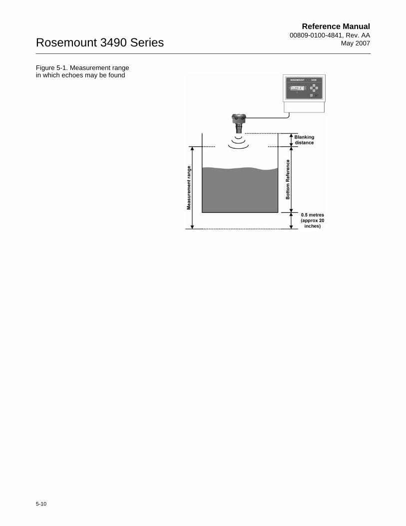
Reference Manual00809-0100-4841, Rev. AA
May 2007Rosemount 3490 Series
5-10
Figure 5-1. Measurement range in which echoes may be found
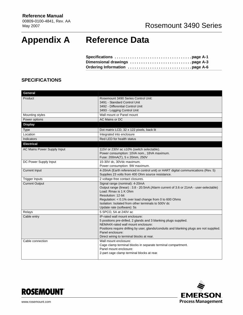
Reference Manual 00809-0100-4841, Rev. AA May 2007 Rosemount 3490 Series
www.rosemount.com
Appendix A Reference Data
Specifications . . . . . . . . . . . . . . . . . . . . . . . . . . . . . . . . . . . page A-1Dimensional drawings . . . . . . . . . . . . . . . . . . . . . . . . . . . . page A-3Ordering Information . . . . . . . . . . . . . . . . . . . . . . . . . . . . . page A-6
SPECIFICATIONS
GeneralProduct Rosemount 3490 Series Control Unit:
3491 - Standard Control Unit3492 - Differential Control Unit3493 - Logging Control Unit
Mounting styles Wall mount or Panel mountPower options AC Mains or DCDisplayType Dot matrix LCD, 32 x 122 pixels, back litLocation Integrated into enclosureIndicators Red LED for health statusElectricalAC Mains Power Supply Input 115V or 230V ac ±10% (switch selectable).
Power consumption: 10VA nom., 18VA maximum.Fuse: 200mA(T), 5 x 20mm, 250V
DC Power Supply Input 15-30V dc, 30Vdc maximum.Power consumption: 9W maximum.
Current Input 4-20mA (Earth referenced in control unit) or HART digital communications (Rev. 5)Supplies 23 volts from 400 Ohm source resistance.
Trigger Inputs 2 voltage-free contact closures.Current Output Signal range (nominal): 4-20mA
Output range (linear) : 3.8 - 20.5mA.(Alarm current of 3.6 or 21mA - user-selectable)Load: Rmax is 1 K OhmResolution: 12-bitRegulation: < 0.1% over load change from 0 to 600 OhmsIsolation: Isolated from other terminals to 500V dcUpdate rate (software): 5s
Relays 5 SPCO, 5A at 240V acCable entry IP-rated wall mount enclosure:
5 positions pre-drilled, 2 glands and 3 blanking plugs supplied.NEMA4X-rated wall mount enclosure:Positions require drilling by user, glands/conduits and blanking plugs are not supplied.Panel enclosure:Direct wiring to terminal blocks at rear.
Cable connection Wall mount enclosure:Cage clamp terminal blocks in separate terminal compartment.Panel mount enclosure:2-part cage clamp terminal blocks at rear.
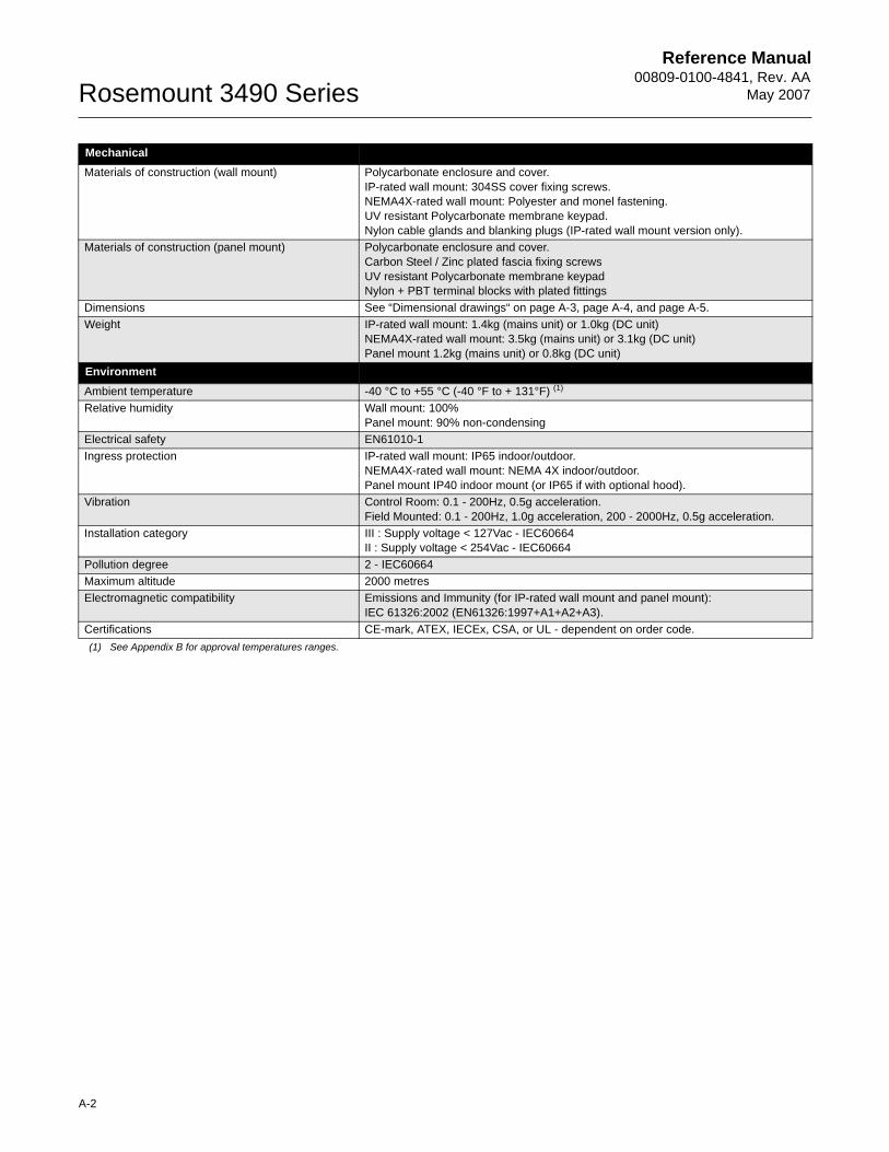
Reference Manual00809-0100-4841, Rev. AA
May 2007Rosemount 3490 Series
A-2
MechanicalMaterials of construction (wall mount) Polycarbonate enclosure and cover.
IP-rated wall mount: 304SS cover fixing screws.NEMA4X-rated wall mount: Polyester and monel fastening.UV resistant Polycarbonate membrane keypad.Nylon cable glands and blanking plugs (IP-rated wall mount version only).
Materials of construction (panel mount) Polycarbonate enclosure and cover.Carbon Steel / Zinc plated fascia fixing screwsUV resistant Polycarbonate membrane keypadNylon + PBT terminal blocks with plated fittings
Dimensions See “Dimensional drawings“ on page A-3, page A-4, and page A-5.Weight IP-rated wall mount: 1.4kg (mains unit) or 1.0kg (DC unit)
NEMA4X-rated wall mount: 3.5kg (mains unit) or 3.1kg (DC unit)Panel mount 1.2kg (mains unit) or 0.8kg (DC unit)
EnvironmentAmbient temperature -40 °C to +55 °C (-40 °F to + 131°F) (1)
Relative humidity Wall mount: 100%Panel mount: 90% non-condensing
Electrical safety EN61010-1Ingress protection IP-rated wall mount: IP65 indoor/outdoor.
NEMA4X-rated wall mount: NEMA 4X indoor/outdoor.Panel mount IP40 indoor mount (or IP65 if with optional hood).
Vibration Control Room: 0.1 - 200Hz, 0.5g acceleration.Field Mounted: 0.1 - 200Hz, 1.0g acceleration, 200 - 2000Hz, 0.5g acceleration.
Installation category III : Supply voltage < 127Vac - IEC60664II : Supply voltage < 254Vac - IEC60664
Pollution degree 2 - IEC60664Maximum altitude 2000 metresElectromagnetic compatibility Emissions and Immunity (for IP-rated wall mount and panel mount):
IEC 61326:2002 (EN61326:1997+A1+A2+A3). Certifications CE-mark, ATEX, IECEx, CSA, or UL - dependent on order code.(1) See Appendix B for approval temperatures ranges.
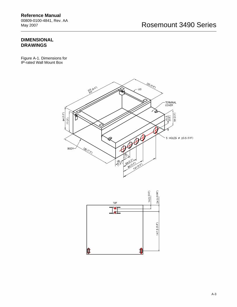
Reference Manual 00809-0100-4841, Rev. AA May 2007
A-3
Rosemount 3490 Series
DIMENSIONAL DRAWINGS
Figure A-1. Dimensions for IP-rated Wall Mount Box
(3”)
(7.3”)
(8.4”)(4.9”)
(1.4”)
(1.1”)
(2.2”)
(3.3”)(5.5”)
(0.8”)
(2.3
”)
(0.8
”)(3.3
”)
(0.6
”)
(0.9
6”)
(5.8
”)
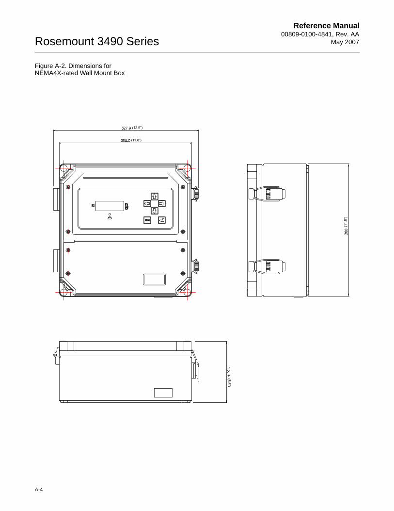
Reference Manual00809-0100-4841, Rev. AA
May 2007Rosemount 3490 Series
A-4
Figure A-2. Dimensions for NEMA4X-rated Wall Mount Box
(11.
8”)
(5.5”)
(11.8”)
(12.9”)
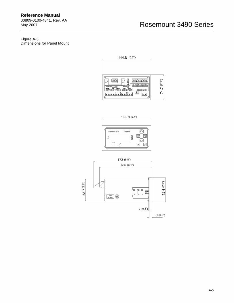
Reference Manual 00809-0100-4841, Rev. AA May 2007
A-5
Rosemount 3490 Series
Figure A-3. Dimensions for Panel Mount
(5.7”)
(6.8”)
(6.1”)(2
.9”)
(0.3”)
(0.1”)
(2.6
”)
(5.7”)
(2.9
”)
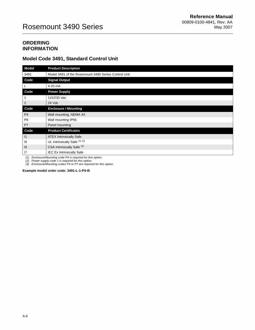
Reference Manual00809-0100-4841, Rev. AA
May 2007Rosemount 3490 Series
A-6
ORDERING INFORMATION
Model Code 3491, Standard Control Unit
Model Product Description
3491 Model 3491 of the Rosemount 3490 Series Control Unit
Code Signal Output
L 4-20 mA
Code Power Supply
1 115/230 Vac2 24 Vdc
Code Enclosure / Mounting
P4 Wall mounting, NEMA 4XP6 Wall mounting IP65P7 Panel mounting
Code Product Certificates
I1 ATEX Intrinsically SafeI5 UL Intrinsically Safe (1) (2)
(1) Enclosure/Mounting code P4 is required for this option.(2) Power supply code 1 is required for this option.
I6 CSA Intrinsically Safe (3)
(3) Enclosure/Mounting codes P4 or P7 are required for this option.
Example model order code: 3491-L-1-P4-I5
I7 IEC Ex Intrinsically Safe
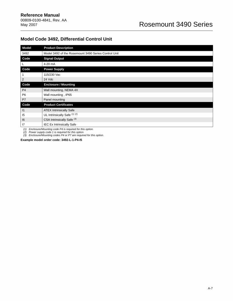
Reference Manual 00809-0100-4841, Rev. AA May 2007
A-7
Rosemount 3490 Series
Model Code 3492, Differential Control Unit
Model Product Description
3492 Model 3492 of the Rosemount 3490 Series Control Unit
Code Signal Output
L 4-20 mA
Code Power Supply
1 115/230 Vac2 24 Vdc
Code Enclosure / Mounting
P4 Wall mounting, NEMA 4XP6 Wall mounting , IP65P7 Panel mounting
Code Product Certificates
I1 ATEX Intrinsically SafeI5 UL Intrinsically Safe (1) (2)
(1) Enclosure/Mounting code P4 is required for this option.(2) Power supply code 1 is required for this option.
I6 CSA Intrinsically Safe (3)
(3) Enclosure/Mounting codes P4 or P7 are required for this option.
Example model order code: 3492-L-1-P4-I5
I7 IEC Ex Intrinsically Safe
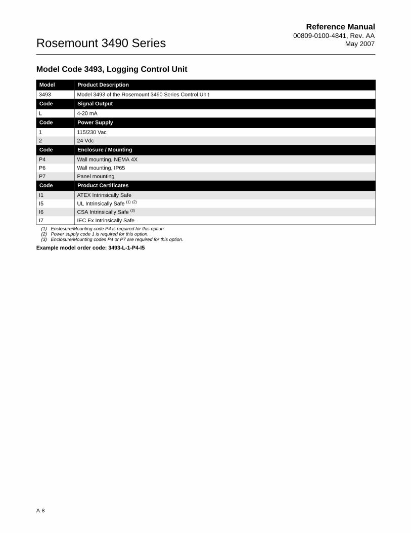
Reference Manual00809-0100-4841, Rev. AA
May 2007Rosemount 3490 Series
A-8
Model Code 3493, Logging Control Unit
Model Product Description
3493 Model 3493 of the Rosemount 3490 Series Control Unit
Code Signal Output
L 4-20 mA
Code Power Supply
1 115/230 Vac2 24 Vdc
Code Enclosure / Mounting
P4 Wall mounting, NEMA 4XP6 Wall mounting, IP65P7 Panel mounting
Code Product Certificates
I1 ATEX Intrinsically SafeI5 UL Intrinsically Safe (1) (2)
(1) Enclosure/Mounting code P4 is required for this option.(2) Power supply code 1 is required for this option.
I6 CSA Intrinsically Safe (3)
(3) Enclosure/Mounting codes P4 or P7 are required for this option.
Example model order code: 3493-L-1-P4-I5
I7 IEC Ex Intrinsically Safe
Reference Manual 00809-0100-4841, Rev. AA May 2007 Rosemount 3490 Series
www.rosemount.com
Appendix B Product Certifications
Safety Messages . . . . . . . . . . . . . . . . . . . . . . . . . . . . . . . . . page B-1European Directive Information . . . . . . . . . . . . . . . . . . . . page B-2Hazardous Locations Certifications . . . . . . . . . . . . . . . . . page B-3Approval Drawings . . . . . . . . . . . . . . . . . . . . . . . . . . . . . . . page B-5
SAFETY MESSAGES Procedures and instructions in this section may require special precautions to ensure the safety of the personnel performing the operations. Information that raises potential safety issues is indicated by a warning symbol ( ). Please refer to the following safety messages before performing an operation preceded by this symbol.
Explosions could result in death or serious injury:Verify that the operating environment of the 3490 Series Control Unit is consistent with the appropriate hazardous locations certifications.
Failure to follow safe installation and servicing guidelines could result in death or serious injury:Make sure the 3490 Series Control Unit is installed by qualified personnel and in accordance with applicable code of practice.
Use the equipment only as specified in this manual. Failure to do so may impair the protection provided by the equipment.
Do not perform any service other than those contained in this manual unless you are qualified.
High voltage that may be present on leads could cause electrical shock:Avoid contact with leads and terminals.
Make sure the main power to the 3490 Series Control Unit is off.
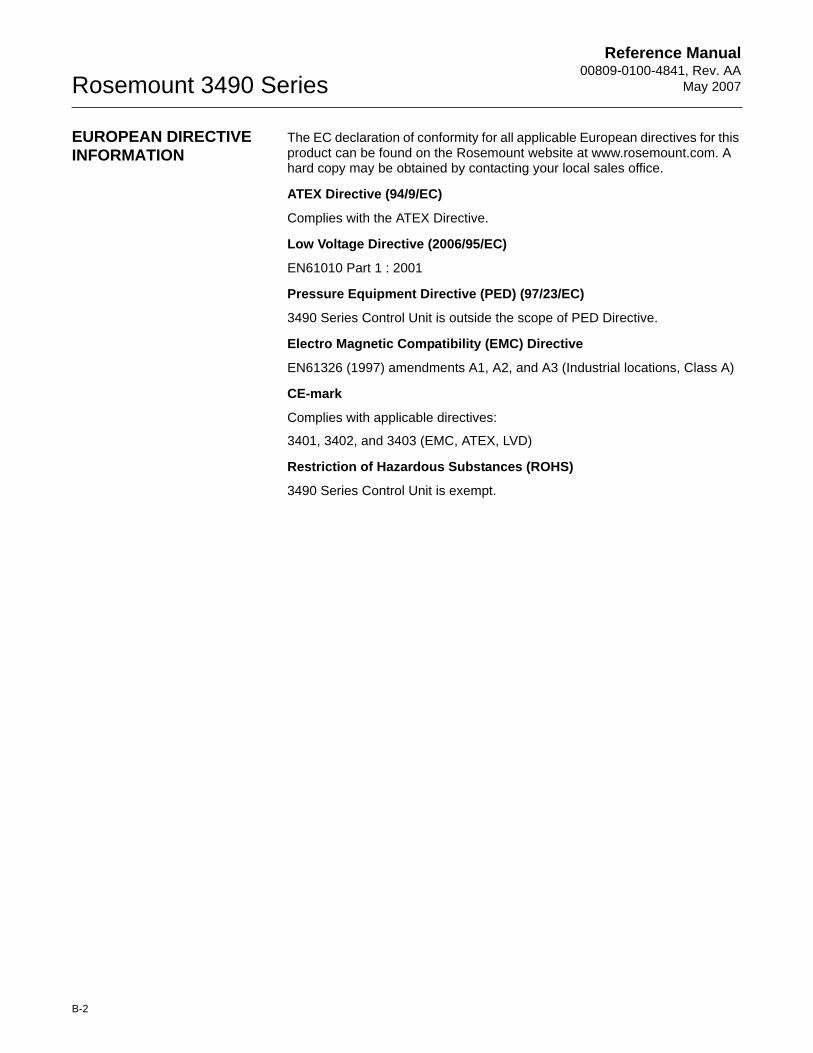
Reference Manual00809-0100-4841, Rev. AA
May 2007Rosemount 3490 Series
B-2
EUROPEAN DIRECTIVE INFORMATION
The EC declaration of conformity for all applicable European directives for this product can be found on the Rosemount website at www.rosemount.com. A hard copy may be obtained by contacting your local sales office.
ATEX Directive (94/9/EC)
Complies with the ATEX Directive.
Low Voltage Directive (2006/95/EC)
EN61010 Part 1 : 2001
Pressure Equipment Directive (PED) (97/23/EC)
3490 Series Control Unit is outside the scope of PED Directive.
Electro Magnetic Compatibility (EMC) Directive
EN61326 (1997) amendments A1, A2, and A3 (Industrial locations, Class A)
CE-mark
Complies with applicable directives:
3401, 3402, and 3403 (EMC, ATEX, LVD)
Restriction of Hazardous Substances (ROHS)
3490 Series Control Unit is exempt.
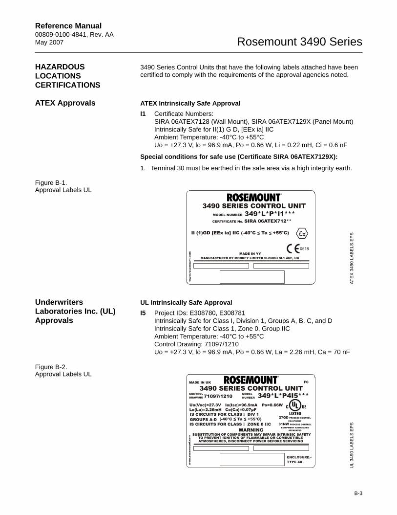
Reference Manual 00809-0100-4841, Rev. AA May 2007
B-3
Rosemount 3490 Series
HAZARDOUS LOCATIONS CERTIFICATIONS
3490 Series Control Units that have the following labels attached have been certified to comply with the requirements of the approval agencies noted.
ATEX Approvals ATEX Intrinsically Safe ApprovalI1 Certificate Numbers:
SIRA 06ATEX7128 (Wall Mount), SIRA 06ATEX7129X (Panel Mount)Intrinsically Safe for II(1) G D, [EEx ia] IICAmbient Temperature: -40°C to +55°CUo = +27.3 V, lo = 96.9 mA, Po = 0.66 W, Li = 0.22 mH, Ci = 0.6 nF
Special conditions for safe use (Certificate SIRA 06ATEX7129X):
1. Terminal 30 must be earthed in the safe area via a high integrity earth.
Figure B-1. Approval Labels UL
Underwriters Laboratories Inc. (UL) Approvals
UL Intrinsically Safe ApprovalI5 Project IDs: E308780, E308781
Intrinsically Safe for Class I, Division 1, Groups A, B, C, and DIntrinsically Safe for Class 1, Zone 0, Group IICAmbient Temperature: -40°C to +55°CControl Drawing: 71097/1210Uo = +27.3 V, lo = 96.9 mA, Po = 0.66 W, La = 2.26 mH, Ca = 70 nF
Figure B-2. Approval Labels UL
0518
ww
w.r
osem
ount
.com
II (1)GD [EEx ia] IIC (-40°C ≤ Ta ≤ +55°C)°
CERTIFICATE No. SIRA 06ATEX712**
3490 SERIES CONTROL UNITMODEL NUMBER 349*L*P*I1***
MANUFACTURED BY MOBREY LIMITED SLOUGH SL1 4UE, UKMADE IN YY
ATEX
349
0 LA
BE
LS.E
PS
Uo(Voc)=27.3V Io(Isc)=96.9mA Po=0.66WLo(La)=2.26mH Co(Ca)=0.07μF
WARNINGSUBSTITUTION OF COMPONENTS MAY IMPAIR INTRINSIC SAFETY
TO PREVENT IGNITION OF FLAMMABLE OR COMBUSTIBLEATMOSPHERES, DISCONNECT POWER BEFORE SERVICING
IS CIRCUITS FOR CLASS DIV 1 I
IS CIRCUITS FOR CLASS ZONE 0 CIII(-40°C ≤ Ta ≤ +55°C)GROUPS A-D
31NW PROCESS CONTROLEQUIPMENT ASSOCIATED
APPARATUS
27GD PROCESS CONTROLEQUIPMENT
MADE IN UK FC
3490 SERIES CONTROL UNIT
ww
w.r
osem
ount
.com
CONTROLDRAWING
MODELNUMBER71097/1210 349*L*P4I5***
ENCLOSURE:-TYPE 4X
UL
3490
LA
BEL
S.E
PS
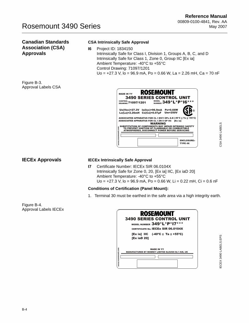
Reference Manual00809-0100-4841, Rev. AA
May 2007Rosemount 3490 Series
B-4
Canadian Standards Association (CSA) Approvals
CSA Intrinsically Safe ApprovalI6 Project ID: 1834150
Intrinsically Safe for Class I, Division 1, Groups A, B, C, and DIntrinsically Safe for Class 1, Zone 0, Group IIC [Ex ia]Ambient Temperature: -40°C to +55°CControl Drawing: 71097/1201Uo = +27.3 V, lo = 96.9 mA, Po = 0.66 W, La = 2.26 mH, Ca = 70 nF
Figure B-3. Approval Labels CSA
IECEx Approvals IECEx Intrinsically Safe ApprovalI7 Certificate Number: IECEx SIR 06.0104X
Intrinsically Safe for Zone 0, 20, [Ex ia] IIC, [Ex iaD 20]Ambient Temperature: -40°C to +55°CUo = +27.3 V, lo = 96.9 mA, Po = 0.66 W, Li = 0.22 mH, Ci = 0.6 nF
Conditions of Certification (Panel Mount):
1. Terminal 30 must be earthed in the safe area via a high integrity earth.
Figure B-4. Approval Labels IECEx
Uo(Voc)=27.3V Io(Isc)=96.9mA Po=0.66WLo(La)=2.26mH Co(Ca)=0.07μF Um=250V
ASSOCIATED APPARATUS FOR CL I ZN 0 GP IIC [Ex ia]WARNING
ww
w.r
osem
ount
.com
SUBSTITUTION OF COMPONENTS MAY IMPAIR INTRINSIC SAFETYTO PREVENT IGNITION OF FLAMMABLE OR COMBUSTIBLEATMOSPHERES, DISCONNECT POWER BEFORE SERVICING
ASSOCIATED APPARATUS FOR CL I DIV1 (-40°C < Ta < +55°C)GPs A-D
MADE IN YY
3490 SERIES CONTROL UNITCONTROLDRAWING
MODELNUMBER71097/1201 349*L*P*I6***
ENCLOSURE:-TYPE 4X
CS
A 3
490
LAB
ELS
Uo(Voc)=27.3V Io(Isc)=96.9mA Po=0.66WLo(La)=2.26mH Co(Ca)=0.07μF
WARNINGSUBSTITUTION OF COMPONENTS MAY IMPAIR INTRINSIC SAFETY
TO PREVENT IGNITION OF FLAMMABLE OR COMBUSTIBLEATMOSPHERES, DISCONNECT POWER BEFORE SERVICING
IS CIRCUITS FOR CLASS DIV 1 I
IS CIRCUITS FOR CLASS ZONE 0 CIII(-40°C ≤ Ta ≤ +55°C)GROUPS A-D
31NW PROCESS CONTROLEQUIPMENT ASSOCIATED
APPARATUS
27GD PROCESS CONTROLEQUIPMENT
MADE IN UK FC
3490 SERIES CONTROL UNIT
ww
w.r
osem
ount
.com
CONTROLDRAWING
MODELNUMBER71097/1210 349*L*P4I5***
ENCLOSURE:-TYPE 4X
MANUFACTURED BY MOBREY LIMITED SLOUGH SL1 4UE, UK
ww
w.r
osem
ount
.com
CERTIFICATE No. IECEx SIR 06.0104X
[Ex ia] IIC (-40ºC ≤ Ta ≤ +55ºC)[Ex iaD 20]
MADE IN YY
3490 SERIES CONTROL UNITMODEL NUMBER 349*L*P*I7***
IEC
EX
3490
LA
BELS
.EPS
Reference Manual 00809-0100-4841, Rev. AA May 2007
B-5
Rosemount 3490 Series
APPROVAL DRAWINGS This section contains installation drawings. You must follow the installation guidelines presented in order to maintain certified ratings.
This section contains the following drawings:• Rosemount Control Drawing 71097/1201, Issue 2:
System Control Drawing for hazardous location installation of intrinsically safe CSA approved apparatus.
• Rosemount Control Drawing 71097/1210, Issue 2:
System Control Drawing for hazardous location installation of intrinsically safe UL approved apparatus.
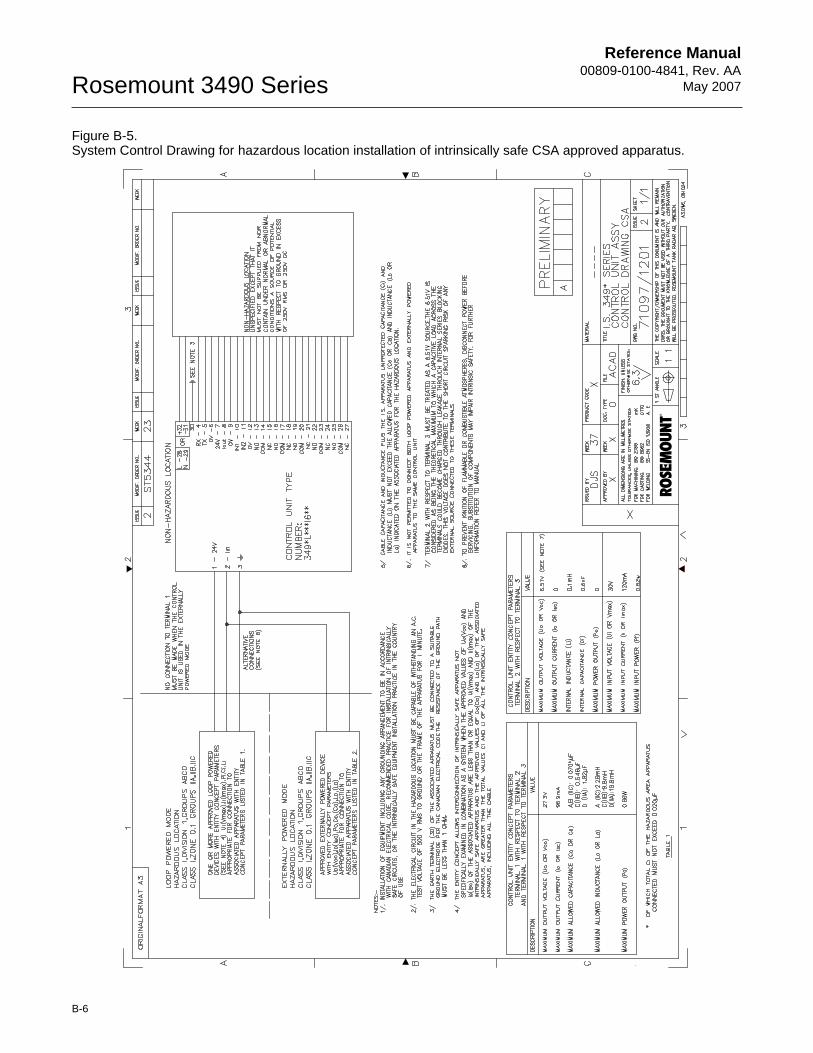
Reference Manual00809-0100-4841, Rev. AA
May 2007Rosemount 3490 Series
B-6
Figure B-5. System Control Drawing for hazardous location installation of intrinsically safe CSA approved apparatus.
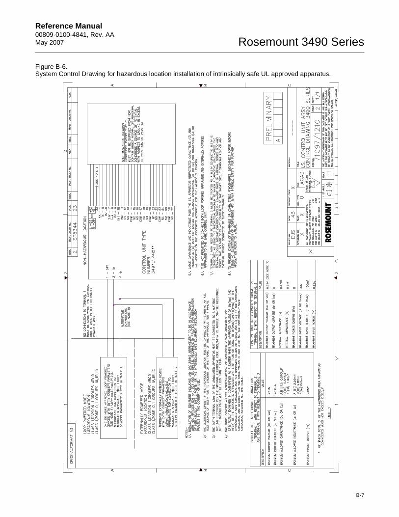
Reference Manual 00809-0100-4841, Rev. AA May 2007
B-7
Rosemount 3490 Series
Figure B-6. System Control Drawing for hazardous location installation of intrinsically safe UL approved apparatus.

Reference Manual00809-0100-4841, Rev. AA
May 2007Rosemount 3490 Series
B-8
Reference Manual 00809-0100-4841, Rev. AA May 2007
C-1
Rosemount 3490 Series
Appendix C Menus and Parameters
Rosemount 3490 Series Control Unit . . . . . . . . . . . . . . . . page C-2Rosemount 3100 Series Transmitter (3102/3105) . . . . . . page C-8
MENUS AND PARAMETERS
This Section contains the menu system maps for:• Rosemount 3490 Series Control Units• Rosemount 3100 Series transmitter (as viewed from the 3490).
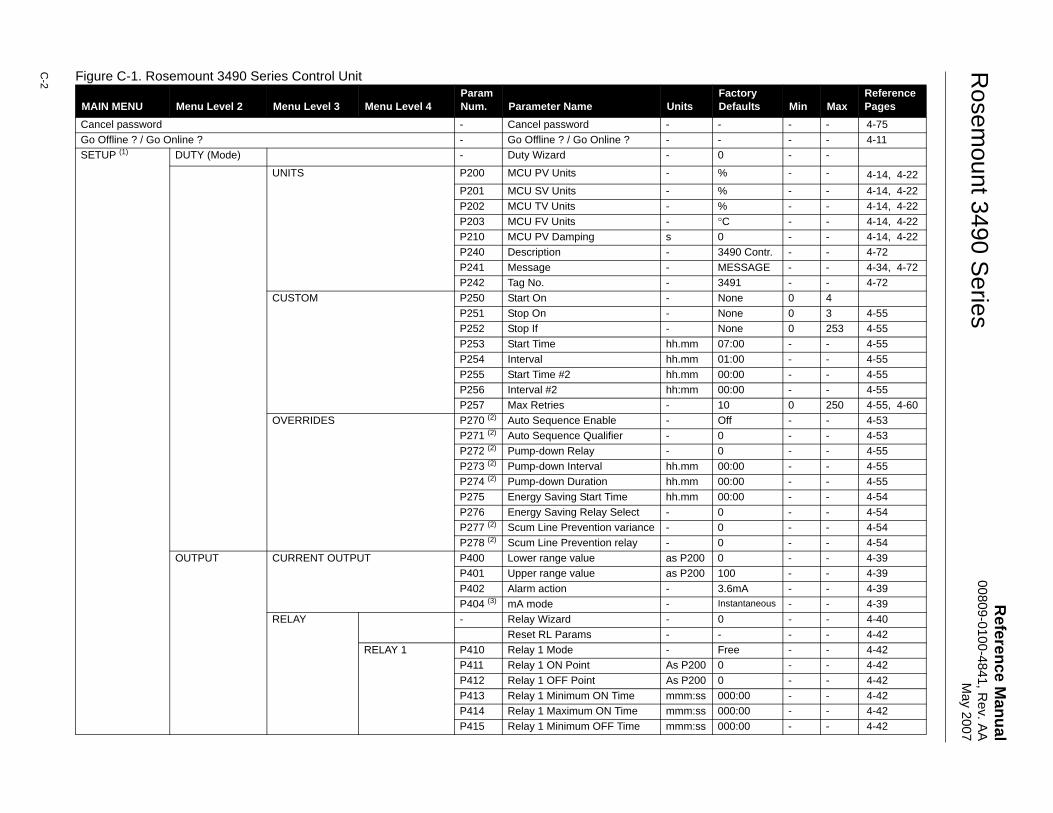
Reference M
anual00809-0100-4841, R
ev. AA
May 2007
Rosem
ount 3490 Series
C-2 Figure C-1. Rosemount 3490 Series Control Unit
MAIN MENU Menu Level 2 Menu Level 3 Menu Level 4ParamNum. Parameter Name Units
Factory Defaults Min Max
Reference Pages
Cancel password - Cancel password - - - - 4-75Go Offline ? / Go Online ? - Go Offline ? / Go Online ? - - - - 4-11SETUP (1) DUTY (Mode) - Duty Wizard - 0 - -
UNITS P200 MCU PV Units - % - - 4-14, 4-22P201 MCU SV Units - % - - 4-14, 4-22P202 MCU TV Units - % - - 4-14, 4-22P203 MCU FV Units - °C - - 4-14, 4-22P210 MCU PV Damping s 0 - - 4-14, 4-22P240 Description - 3490 Contr. - - 4-72P241 Message - MESSAGE - - 4-34, 4-72P242 Tag No. - 3491 - - 4-72
CUSTOM P250 Start On - None 0 4P251 Stop On - None 0 3 4-55P252 Stop If - None 0 253 4-55P253 Start Time hh.mm 07:00 - - 4-55P254 Interval hh.mm 01:00 - - 4-55P255 Start Time #2 hh.mm 00:00 - - 4-55P256 Interval #2 hh:mm 00:00 - - 4-55P257 Max Retries - 10 0 250 4-55, 4-60
OVERRIDES P270 (2) Auto Sequence Enable - Off - - 4-53P271 (2) Auto Sequence Qualifier - 0 - - 4-53P272 (2) Pump-down Relay - 0 - - 4-55P273 (2) Pump-down Interval hh.mm 00:00 - - 4-55P274 (2) Pump-down Duration hh.mm 00:00 - - 4-55P275 Energy Saving Start Time hh.mm 00:00 - - 4-54P276 Energy Saving Relay Select - 0 - - 4-54P277 (2) Scum Line Prevention variance - 0 - - 4-54P278 (2) Scum Line Prevention relay - 0 - - 4-54
OUTPUT CURRENT OUTPUT P400 Lower range value as P200 0 - - 4-39P401 Upper range value as P200 100 - - 4-39P402 Alarm action - 3.6mA - - 4-39P404 (3) mA mode - Instantaneous - - 4-39
RELAY - Relay Wizard - 0 - - 4-40Reset RL Params - - - - 4-42
RELAY 1 P410 Relay 1 Mode - Free - - 4-42P411 Relay 1 ON Point As P200 0 - - 4-42P412 Relay 1 OFF Point As P200 0 - - 4-42P413 Relay 1 Minimum ON Time mmm:ss 000:00 - - 4-42P414 Relay 1 Maximum ON Time mmm:ss 000:00 - - 4-42P415 Relay 1 Minimum OFF Time mmm:ss 000:00 - - 4-42
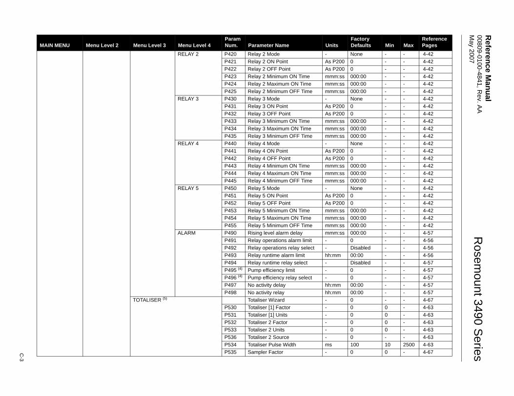
Reference M
anual 00809-0100-4841, R
ev. AA
M
ay 2007
C-3
Rosem
ount 3490 Series
RELAY 2 P420 Relay 2 Mode - None - - 4-42P421 Relay 2 ON Point As P200 0 - - 4-42P422 Relay 2 OFF Point As P200 0 - - 4-42P423 Relay 2 Minimum ON Time mmm:ss 000:00 - - 4-42P424 Relay 2 Maximum ON Time mmm:ss 000:00 - - 4-42P425 Relay 2 Minimum OFF Time mmm:ss 000:00 - - 4-42
RELAY 3 P430 Relay 3 Mode - None - - 4-42P431 Relay 3 ON Point As P200 0 - - 4-42P432 Relay 3 OFF Point As P200 0 - - 4-42P433 Relay 3 Minimum ON Time mmm:ss 000:00 - - 4-42P434 Relay 3 Maximum ON Time mmm:ss 000:00 - - 4-42P435 Relay 3 Minimum OFF Time mmm:ss 000:00 - - 4-42
RELAY 4 P440 Relay 4 Mode - None - - 4-42P441 Relay 4 ON Point As P200 0 - - 4-42P442 Relay 4 OFF Point As P200 0 - - 4-42P443 Relay 4 Minimum ON Time mmm:ss 000:00 - - 4-42P444 Relay 4 Maximum ON Time mmm:ss 000:00 - - 4-42P445 Relay 4 Minimum OFF Time mmm:ss 000:00 - - 4-42
RELAY 5 P450 Relay 5 Mode - None - - 4-42P451 Relay 5 ON Point As P200 0 - - 4-42P452 Relay 5 OFF Point As P200 0 - - 4-42P453 Relay 5 Minimum ON Time mmm:ss 000:00 - - 4-42P454 Relay 5 Maximum ON Time mmm:ss 000:00 - - 4-42P455 Relay 5 Minimum OFF Time mmm:ss 000:00 - - 4-42
ALARM P490 Rising level alarm delay mmm:ss 000:00 - - 4-57P491 Relay operations alarm limit - 0 - - 4-56P492 Relay operations relay select - Disabled - - 4-56P493 Relay runtime alarm limit hh:mm 00:00 - - 4-56P494 Relay runtime relay select - Disabled - - 4-57P495 (4) Pump efficiency limit - 0 - - 4-57P496 (4) Pump efficiency relay select - 0 - - 4-57P497 No activity delay hh:mm 00:00 - - 4-57P498 No activity relay hh:mm 00:00 - - 4-57
TOTALISER (5) Totaliser Wizard - 0 - - 4-67P530 Totaliser [1] Factor - 0 0 - 4-63P531 Totaliser [1] Units - 0 0 - 4-63P532 Totaliser 2 Factor - 0 0 - 4-63P533 Totaliser 2 Units - 0 0 - 4-63P536 Totaliser 2 Source - 0 - - 4-63P534 Totaliser Pulse Width ms 100 10 2500 4-63P535 Sampler Factor - 0 0 - 4-67
MAIN MENU Menu Level 2 Menu Level 3 Menu Level 4ParamNum. Parameter Name Units
Factory Defaults Min Max
Reference Pages
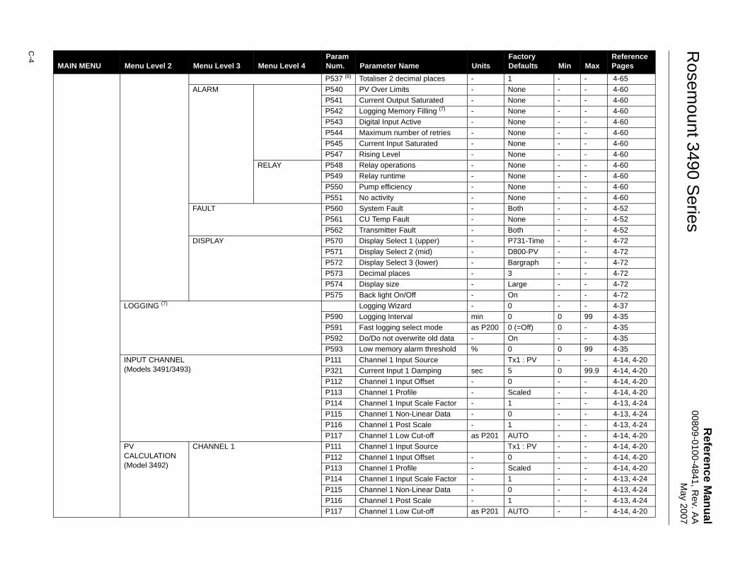
Reference M
anual00809-0100-4841, R
ev. AA
May 2007
Rosem
ount 3490 Series
C-4
P537 (6) Totaliser 2 decimal places - 1 - - 4-65ALARM P540 PV Over Limits - None - - 4-60
P541 Current Output Saturated - None - - 4-60P542 Logging Memory Filling (7) - None - - 4-60P543 Digital Input Active - None - - 4-60P544 Maximum number of retries - None - - 4-60P545 Current Input Saturated - None - - 4-60P547 Rising Level - None - - 4-60
RELAY P548 Relay operations - None - - 4-60P549 Relay runtime - None - - 4-60P550 Pump efficiency - None - - 4-60P551 No activity - None - - 4-60
FAULT P560 System Fault - Both - - 4-52P561 CU Temp Fault - None - - 4-52P562 Transmitter Fault - Both - - 4-52
DISPLAY P570 Display Select 1 (upper) - P731-Time - - 4-72P571 Display Select 2 (mid) - D800-PV - - 4-72P572 Display Select 3 (lower) - Bargraph - - 4-72P573 Decimal places - 3 - - 4-72P574 Display size - Large - - 4-72P575 Back light On/Off - On - - 4-72
LOGGING (7) Logging Wizard - 0 - - 4-37P590 Logging Interval min 0 0 99 4-35P591 Fast logging select mode as P200 0 (=Off) 0 - 4-35P592 Do/Do not overwrite old data - On - - 4-35P593 Low memory alarm threshold % 0 0 99 4-35
INPUT CHANNEL(Models 3491/3493)
P111 Channel 1 Input Source Tx1 : PV - - 4-14, 4-20P321 Current Input 1 Damping sec 5 0 99.9 4-14, 4-20P112 Channel 1 Input Offset - 0 - - 4-14, 4-20P113 Channel 1 Profile - Scaled - - 4-14, 4-20P114 Channel 1 Input Scale Factor - 1 - - 4-13, 4-24P115 Channel 1 Non-Linear Data - 0 - - 4-13, 4-24P116 Channel 1 Post Scale - 1 - - 4-13, 4-24P117 Channel 1 Low Cut-off as P201 AUTO - - 4-14, 4-20
PV CALCULATION(Model 3492)
CHANNEL 1 P111 Channel 1 Input Source Tx1 : PV - - 4-14, 4-20P112 Channel 1 Input Offset - 0 - - 4-14, 4-20P113 Channel 1 Profile - Scaled - - 4-14, 4-20P114 Channel 1 Input Scale Factor - 1 - - 4-13, 4-24P115 Channel 1 Non-Linear Data - 0 - - 4-13, 4-24P116 Channel 1 Post Scale - 1 - - 4-13, 4-24P117 Channel 1 Low Cut-off as P201 AUTO - - 4-14, 4-20
MAIN MENU Menu Level 2 Menu Level 3 Menu Level 4ParamNum. Parameter Name Units
Factory Defaults Min Max
Reference Pages
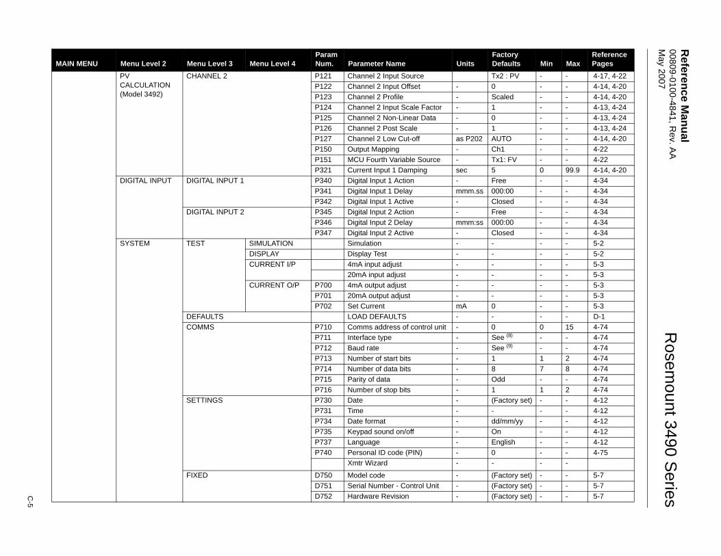
Reference M
anual 00809-0100-4841, R
ev. AA
M
ay 2007
C-5
Rosem
ount 3490 Series
PV CALCULATION(Model 3492)
CHANNEL 2 P121 Channel 2 Input Source Tx2 : PV - - 4-17, 4-22P122 Channel 2 Input Offset - 0 - - 4-14, 4-20P123 Channel 2 Profile - Scaled - - 4-14, 4-20P124 Channel 2 Input Scale Factor - 1 - - 4-13, 4-24P125 Channel 2 Non-Linear Data - 0 - - 4-13, 4-24P126 Channel 2 Post Scale - 1 - - 4-13, 4-24P127 Channel 2 Low Cut-off as P202 AUTO - - 4-14, 4-20P150 Output Mapping - Ch1 - - 4-22P151 MCU Fourth Variable Source - Tx1: FV - - 4-22P321 Current Input 1 Damping sec 5 0 99.9 4-14, 4-20
DIGITAL INPUT DIGITAL INPUT 1 P340 Digital Input 1 Action - Free - - 4-34P341 Digital Input 1 Delay mmm.ss 000:00 - - 4-34P342 Digital Input 1 Active - Closed - - 4-34
DIGITAL INPUT 2 P345 Digital Input 2 Action - Free - - 4-34P346 Digital Input 2 Delay mmm:ss 000:00 - - 4-34P347 Digital Input 2 Active - Closed - - 4-34
SYSTEM TEST SIMULATION Simulation - - - - 5-2DISPLAY Display Test - - - - 5-2CURRENT I/P 4mA input adjust - - - - 5-3
20mA input adjust - - - - 5-3CURRENT O/P P700 4mA output adjust - - - - 5-3
P701 20mA output adjust - - - - 5-3P702 Set Current mA 0 - - 5-3
DEFAULTS LOAD DEFAULTS - - - - D-1COMMS P710 Comms address of control unit - 0 0 15 4-74
P711 Interface type - See (8) - - 4-74P712 Baud rate - See (9) - - 4-74P713 Number of start bits - 1 1 2 4-74P714 Number of data bits - 8 7 8 4-74P715 Parity of data - Odd - - 4-74P716 Number of stop bits - 1 1 2 4-74
SETTINGS P730 Date - (Factory set) - - 4-12P731 Time - - - - 4-12P734 Date format - dd/mm/yy - - 4-12P735 Keypad sound on/off - On - - 4-12P737 Language - English - - 4-12P740 Personal ID code (PIN) - 0 - - 4-75
Xmtr Wizard - - - -
FIXED D750 Model code - (Factory set) - - 5-7D751 Serial Number - Control Unit - (Factory set) - - 5-7D752 Hardware Revision - (Factory set) - - 5-7
MAIN MENU Menu Level 2 Menu Level 3 Menu Level 4ParamNum. Parameter Name Units
Factory Defaults Min Max
Reference Pages
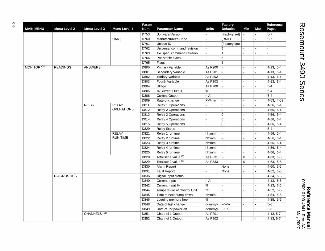
Reference M
anual00809-0100-4841, R
ev. AA
May 2007
Rosem
ount 3490 Series
C-6
D753 Software Version - (Factory set) - - 5-7HART D760 Manufacturer’s Code - (RMT) - - 5-7
D761 Unique ID - (Factory set) - - -D762 Universal command revision - 5 - - -D763 Txr spec. command revision - 1 - - -D764 Pre-amble bytes - 5 - - -D765 Flags - 1 - - -
MONITOR (10) READINGS ANSWERS D800 Primary Variable As P200 - - - 4-13, 5-4D801 Secondary Variable As P201 - - - 4-13, 5-4D802 Tertiary Variable As P202 - - - 4-13, 5-4D803 Fourth Variable As P203 - - - 4-13, 5-4D804 Ullage As P200 - - - 5-4D805 % Current Output % - - - 5-4D806 Current Output mA - - - 5-4D809 Rate of change PV/min - - - 4-53, 4-59
RELAY RELAY OPERATIONS
D811 Relay 1 Operations - 0 - - 4-56, 5-4D812 Relay 2 Operations - 0 - - 4-56, 5-4D813 Relay 3 Operations - 0 - - 4-56, 5-4D814 Relay 4 Operations - 0 - - 4-56, 5-4D815 Relay 5 Operations - 0 - - 4-56, 5-4D820 Relay Status - - - - 5-4
RELAYRUN TIME
D821 Relay 1 runtime hh:mm - - - 4-56, 5-4D822 Relay 2 runtime hh:mm - - - 4-56, 5-4D823 Relay 3 runtime hh:mm - - - 4-56, 5-4D824 Relay 4 runtime hh:mm - - - 4-56, 5-4D825 Relay 5 runtime hh:mm - - - 4-56, 5-4D828 Totaliser 1 value (5) As P531 - 0 - 4-63, 5-5D829 Totaliser 2 value (5) As P533 - 0 - 4-63, 5-5D830 Alarm Report - None - - 4-60, 5-5D831 Fault Report - None - - 4-52, 5-5
DIAGNOSTICS D835 Digital Input status - - - - 4-34, 5-6D840 Current Input mA - - - 4-13, 5-6D842 Current Input % % - - - 4-13, 5-6D844 Temperature of Control Unit °C - - - 4-52, 5-6D845 Time to next pump-down hh:mm - - - 4-54, 5-6D846 Logging memory free (7) % - - - 4-35, 5-6D848 Date of last change ddmmyy --/--/-- - - 5-6D849 Data of 1st power-on ddmmyy --/--/-- - - 5-6
CHANNELS (11) D851 Channel 1 Output As P201 - - - 4-13, 5-7D852 Channel 2 Output As P202 - - - 4-13, 5-7
MAIN MENU Menu Level 2 Menu Level 3 Menu Level 4ParamNum. Parameter Name Units
Factory Defaults Min Max
Reference Pages
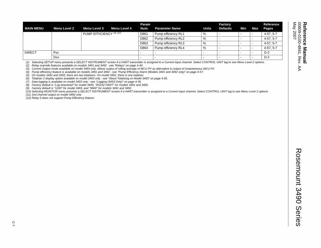
Reference M
anual 00809-0100-4841, R
ev. AA
M
ay 2007
C-7
Rosem
ount 3490 Series
PUMP EFFICIENCY (4) (12) D861 Pump efficiency RL1 % - - - 4-57, 5-7D862 Pump efficiency RL2 % - - - 4-57, 5-7D863 Pump efficiency RL3 % - - - 4-57, 5-7D864 Pump efficiency RL4 % - - - 4-57, 5-7
DIRECT Pxx - - - - - - D-2Dxx - - - - - - D-2
(1) Selecting SETUP menu presents a SELECT INSTRUMENT screen if a HART transmitter is assigned to a Current Input channel. Select CONTROL UNIT tag to see Menu Level 2 options.(2) Relay override features available on models 3491 and 3492 - see “Relays” on page 4-40.(3) Current Output mode available on model 3493 only. Allows output of rolling average of MCU PV as alternative to output of instantaneous MCU PV.(4) Pump efficiency feature is available on models 3491 and 3492 - see “Pump Efficiency Alarm (Models 3491 and 3492 only)” on page 4-57.(5) On models 3492 and 3493, there are two totalisers. On model 3491, there is one totaliser.(6) Totaliser 2 display option available on model 3493 only - see “About Totalising on Model 3493” on page 4-65.(7) Data logging is available on model 3493 only - see “Logging (3493 Only)” on page 4-35.(8) Factory default is "Log download" for model 3493, "RS232 HART" for models 3491 and 3492.(9) Factory default is "1200" for model 3493, and "9600" for models 3491 and 3492.(10) Selecting MONITOR menu presents a SELECT INSTRUMENT screen if a HART transmitter is assigned to a Current Input channel. Select CONTROL UNIT tag to see Menu Level 2 options.(11) 2nd channel output on model 3492 only.(12) Relay 5 does not support Pump Efficiency feature.
MAIN MENU Menu Level 2 Menu Level 3 Menu Level 4ParamNum. Parameter Name Units
Factory Defaults Min Max
Reference Pages
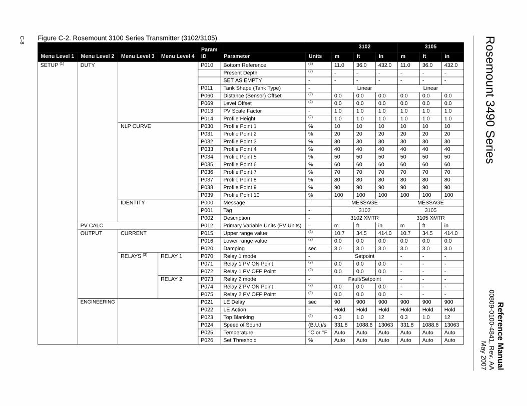
Reference M
anual00809-0100-4841, R
ev. AA
May 2007
Rosem
ount 3490 Series
C-8 Figure C-2. Rosemount 3100 Series Transmitter (3102/3105)
ParamID
3102 3105
Menu Level 1 Menu Level 2 Menu Level 3 Menu Level 4 Parameter Units m ft In m ft inSETUP (1) DUTY P010 Bottom Reference (2) 11.0 36.0 432.0 11.0 36.0 432.0
Present Depth (2) - - - - - -SET AS EMPTY - - - - - - -
P011 Tank Shape (Tank Type) - Linear LinearP060 Distance (Sensor) Offset (2) 0.0 0.0 0.0 0.0 0.0 0.0P069 Level Offset (2) 0.0 0.0 0.0 0.0 0.0 0.0P013 PV Scale Factor - 1.0 1.0 1.0 1.0 1.0 1.0P014 Profile Height (2) 1.0 1.0 1.0 1.0 1.0 1.0
NLP CURVE P030 Profile Point 1 % 10 10 10 10 10 10P031 Profile Point 2 % 20 20 20 20 20 20P032 Profile Point 3 % 30 30 30 30 30 30P033 Profile Point 4 % 40 40 40 40 40 40P034 Profile Point 5 % 50 50 50 50 50 50P035 Profile Point 6 % 60 60 60 60 60 60P036 Profile Point 7 % 70 70 70 70 70 70P037 Profile Point 8 % 80 80 80 80 80 80P038 Profile Point 9 % 90 90 90 90 90 90P039 Profile Point 10 % 100 100 100 100 100 100
IDENTITY P000 Message - MESSAGE MESSAGEP001 Tag - 3102 3105P002 Description - 3102 XMTR 3105 XMTR
PV CALC P012 Primary Variable Units (PV Units) - m ft in m ft inOUTPUT CURRENT P015 Upper range value (2) 10.7 34.5 414.0 10.7 34.5 414.0
P016 Lower range value (2) 0.0 0.0 0.0 0.0 0.0 0.0P020 Damping sec 3.0 3.0 3.0 3.0 3.0 3.0
RELAYS (3) RELAY 1 P070 Relay 1 mode - Setpoint - - -P071 Relay 1 PV ON Point (2) 0.0 0.0 0.0 - - -P072 Relay 1 PV OFF Point (2) 0.0 0.0 0.0 - - -
RELAY 2 P073 Relay 2 mode - Fault/Setpoint - - -P074 Relay 2 PV ON Point (2) 0.0 0.0 0.0 - - -P075 Relay 2 PV OFF Point (2) 0.0 0.0 0.0 - - -
ENGINEERING P021 LE Delay sec 90 900 900 900 900 900P022 LE Action - Hold Hold Hold Hold Hold HoldP023 Top Blanking (2) 0.3 1.0 12 0.3 1.0 12P024 Speed of Sound (B.U.)/s 331.8 1088.6 13063 331.8 1088.6 13063P025 Temperature °C or °F Auto Auto Auto Auto Auto AutoP026 Set Threshold % Auto Auto Auto Auto Auto Auto
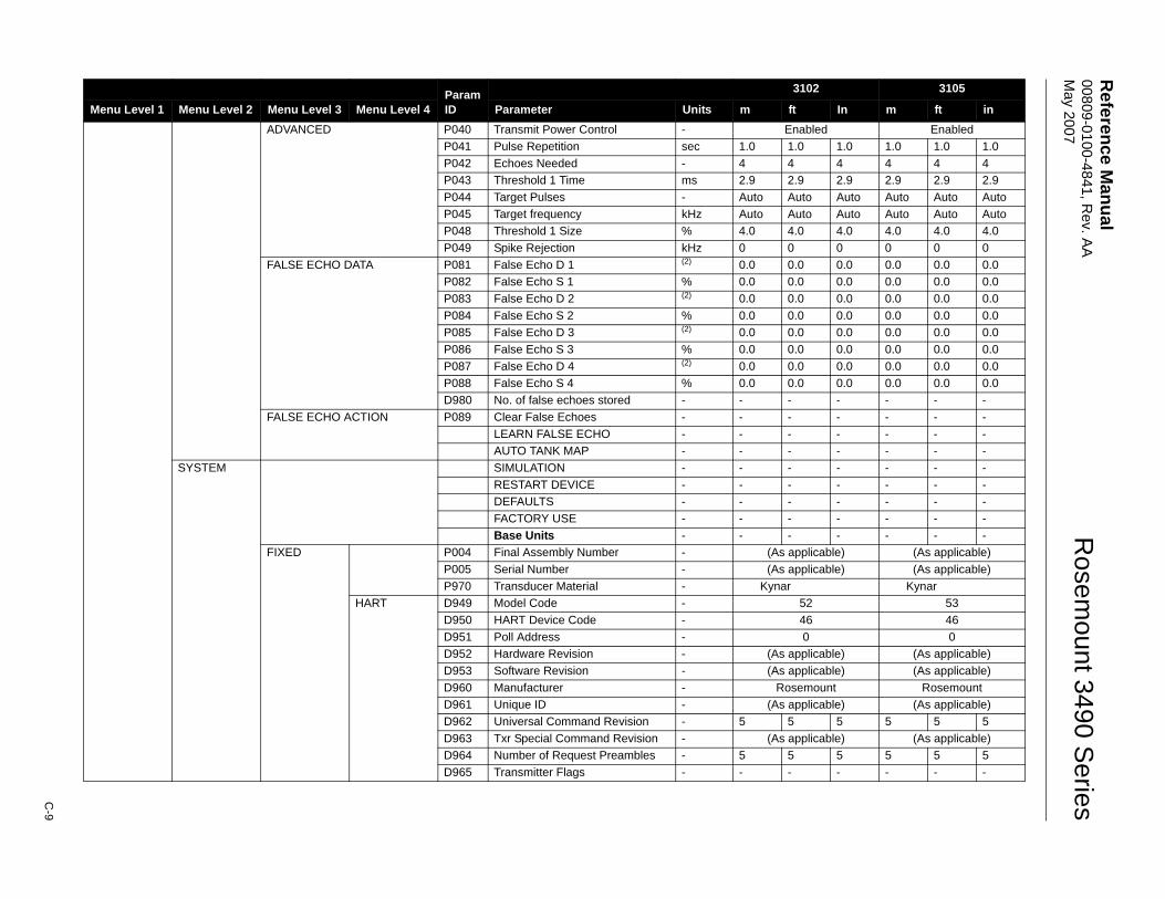
Reference M
anual 00809-0100-4841, R
ev. AA
M
ay 2007
C-9
Rosem
ount 3490 Series
ADVANCED P040 Transmit Power Control - Enabled EnabledP041 Pulse Repetition sec 1.0 1.0 1.0 1.0 1.0 1.0P042 Echoes Needed - 4 4 4 4 4 4P043 Threshold 1 Time ms 2.9 2.9 2.9 2.9 2.9 2.9P044 Target Pulses - Auto Auto Auto Auto Auto AutoP045 Target frequency kHz Auto Auto Auto Auto Auto AutoP048 Threshold 1 Size % 4.0 4.0 4.0 4.0 4.0 4.0P049 Spike Rejection kHz 0 0 0 0 0 0
FALSE ECHO DATA P081 False Echo D 1 (2) 0.0 0.0 0.0 0.0 0.0 0.0P082 False Echo S 1 % 0.0 0.0 0.0 0.0 0.0 0.0P083 False Echo D 2 (2) 0.0 0.0 0.0 0.0 0.0 0.0P084 False Echo S 2 % 0.0 0.0 0.0 0.0 0.0 0.0P085 False Echo D 3 (2) 0.0 0.0 0.0 0.0 0.0 0.0P086 False Echo S 3 % 0.0 0.0 0.0 0.0 0.0 0.0P087 False Echo D 4 (2) 0.0 0.0 0.0 0.0 0.0 0.0P088 False Echo S 4 % 0.0 0.0 0.0 0.0 0.0 0.0D980 No. of false echoes stored - - - - - - -
FALSE ECHO ACTION P089 Clear False Echoes - - - - - - -LEARN FALSE ECHO - - - - - - -AUTO TANK MAP - - - - - - -
SYSTEM SIMULATION - - - - - - -RESTART DEVICE - - - - - - -DEFAULTS - - - - - - -FACTORY USE - - - - - - -Base Units - - - - - - -
FIXED P004 Final Assembly Number - (As applicable) (As applicable)P005 Serial Number - (As applicable) (As applicable)P970 Transducer Material - Kynar Kynar
HART D949 Model Code - 52 53D950 HART Device Code - 46 46D951 Poll Address - 0 0D952 Hardware Revision - (As applicable) (As applicable)D953 Software Revision - (As applicable) (As applicable)D960 Manufacturer - Rosemount RosemountD961 Unique ID - (As applicable) (As applicable)D962 Universal Command Revision - 5 5 5 5 5 5D963 Txr Special Command Revision - (As applicable) (As applicable)D964 Number of Request Preambles - 5 5 5 5 5 5D965 Transmitter Flags - - - - - - -
ParamID
3102 3105
Menu Level 1 Menu Level 2 Menu Level 3 Menu Level 4 Parameter Units m ft In m ft in
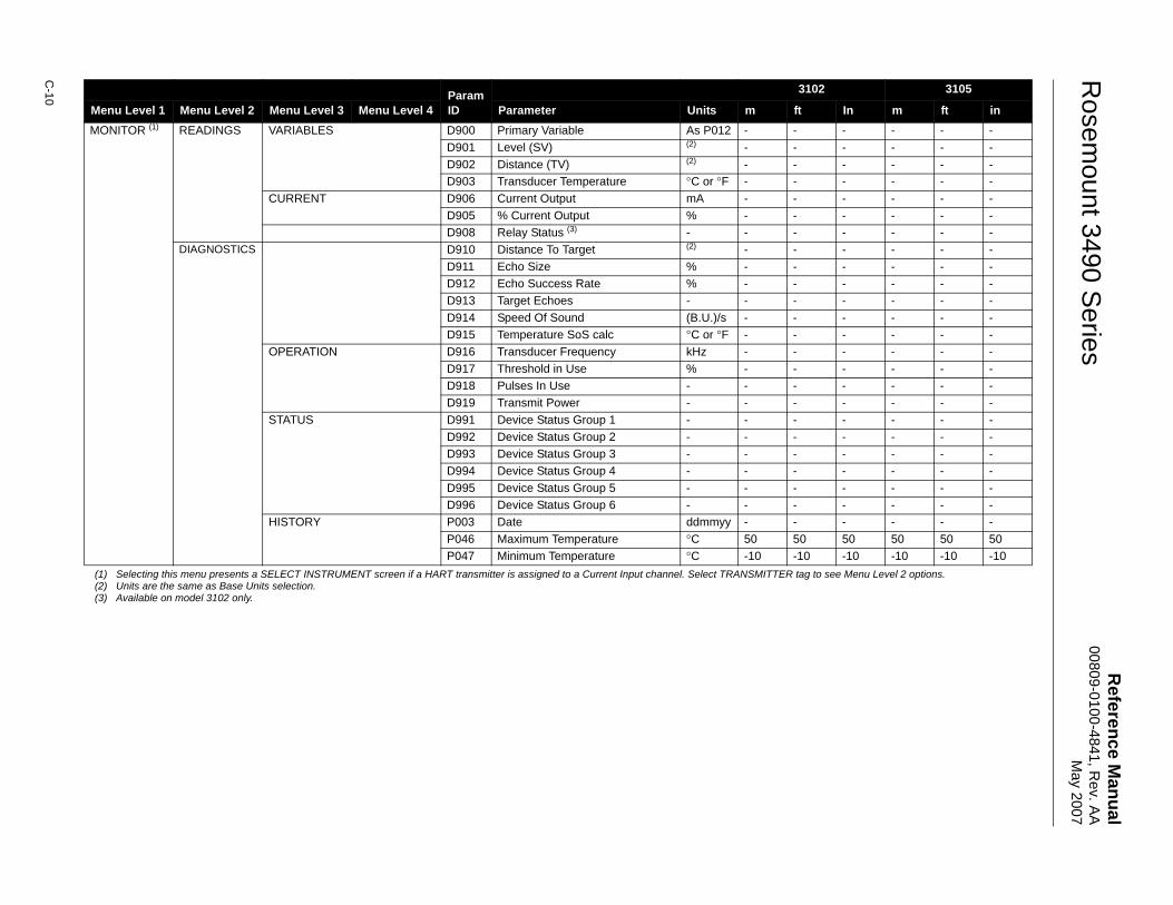
Reference M
anual00809-0100-4841, R
ev. AA
May 2007
Rosem
ount 3490 Series
C-10
MONITOR (1) READINGS VARIABLES D900 Primary Variable As P012 - - - - - -D901 Level (SV) (2) - - - - - -D902 Distance (TV) (2) - - - - - -D903 Transducer Temperature °C or °F - - - - - -
CURRENT D906 Current Output mA - - - - - -D905 % Current Output % - - - - - -D908 Relay Status (3) - - - - - - -
DIAGNOSTICS D910 Distance To Target (2) - - - - - -D911 Echo Size % - - - - - -D912 Echo Success Rate % - - - - - -D913 Target Echoes - - - - - - -D914 Speed Of Sound (B.U.)/s - - - - - -D915 Temperature SoS calc °C or °F - - - - - -
OPERATION D916 Transducer Frequency kHz - - - - - -D917 Threshold in Use % - - - - - -D918 Pulses In Use - - - - - - -D919 Transmit Power - - - - - - -
STATUS D991 Device Status Group 1 - - - - - - -D992 Device Status Group 2 - - - - - - -D993 Device Status Group 3 - - - - - - -D994 Device Status Group 4 - - - - - - -D995 Device Status Group 5 - - - - - - -D996 Device Status Group 6 - - - - - - -
HISTORY P003 Date ddmmyy - - - - - -P046 Maximum Temperature °C 50 50 50 50 50 50P047 Minimum Temperature °C -10 -10 -10 -10 -10 -10
(1) Selecting this menu presents a SELECT INSTRUMENT screen if a HART transmitter is assigned to a Current Input channel. Select TRANSMITTER tag to see Menu Level 2 options.(2) Units are the same as Base Units selection.(3) Available on model 3102 only.
ParamID
3102 3105
Menu Level 1 Menu Level 2 Menu Level 3 Menu Level 4 Parameter Units m ft In m ft in
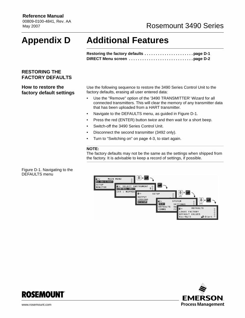
Reference Manual 00809-0100-4841, Rev. AA May 2007 Rosemount 3490 Series
www.rosemount.com
Appendix D Additional FeaturesRestoring the factory defaults . . . . . . . . . . . . . . . . . . . . . . page D-1DIRECT Menu screen . . . . . . . . . . . . . . . . . . . . . . . . . . . . . page D-2
RESTORING THE FACTORY DEFAULTS
How to restore the factory default settings
Use the following sequence to restore the 3490 Series Control Unit to the factory defaults, erasing all user entered data:• Use the "Remove" option of the '3490 TRANSMITTER' Wizard for all
connected transmitters. This will clear the memory of any transmitter data that has been uploaded from a HART transmitter.
• Navigate to the DEFAULTS menu, as guided in Figure D-1.• Press the red (ENTER) button twice and then wait for a short beep.• Switch-off the 3490 Series Control Unit.• Disconnect the second transmitter (3492 only).• Turn to “Switching on” on page 4-3, to start again.
NOTE:The factory defaults may not be the same as the settings when shipped from the factory. It is advisable to keep a record of settings, if possible.
Figure D-1. Navigating to the DEFAULTS menu
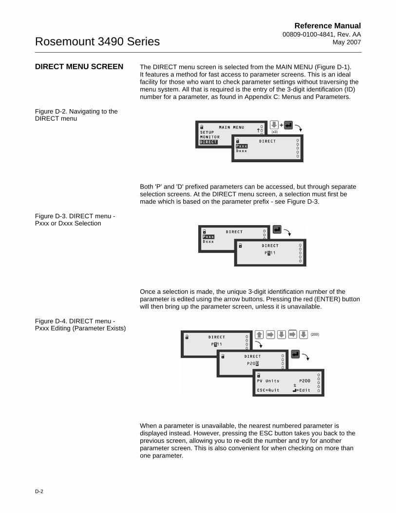
Reference Manual00809-0100-4841, Rev. AA
May 2007Rosemount 3490 Series
D-2
DIRECT MENU SCREEN The DIRECT menu screen is selected from the MAIN MENU (Figure D-1).It features a method for fast access to parameter screens. This is an ideal facility for those who want to check parameter settings without traversing the menu system. All that is required is the entry of the 3-digit identification (ID) number for a parameter, as found in Appendix C: Menus and Parameters.
Figure D-2. Navigating to the DIRECT menu
Both 'P' and 'D' prefixed parameters can be accessed, but through separate selection screens. At the DIRECT menu screen, a selection must first be made which is based on the parameter prefix - see Figure D-3.
Figure D-3. DIRECT menu - Pxxx or Dxxx Selection
Once a selection is made, the unique 3-digit identification number of the parameter is edited using the arrow buttons. Pressing the red (ENTER) button will then bring up the parameter screen, unless it is unavailable.
Figure D-4. DIRECT menu - Pxxx Editing (Parameter Exists)
When a parameter is unavailable, the nearest numbered parameter is displayed instead. However, pressing the ESC button takes you back to the previous screen, allowing you to re-edit the number and try for another parameter screen. This is also convenient for when checking on more than one parameter.
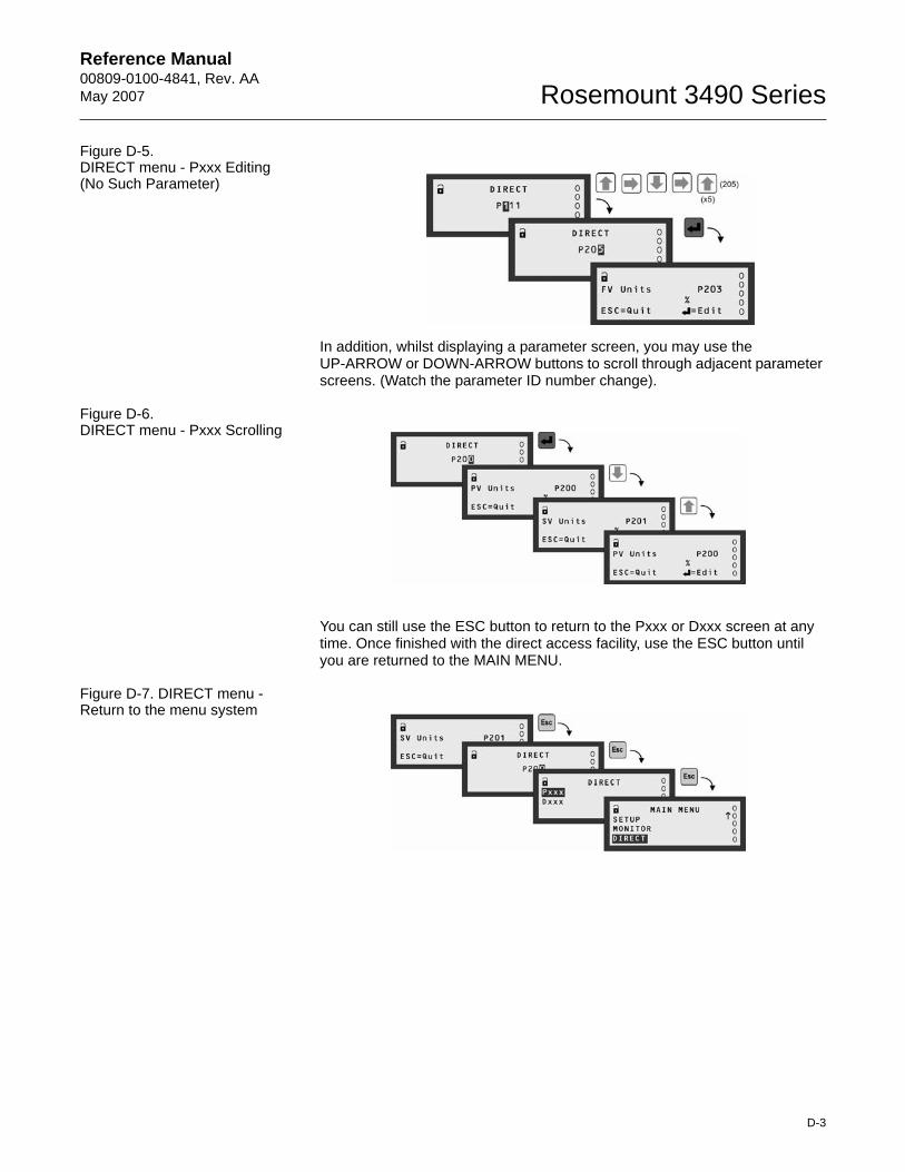
Reference Manual 00809-0100-4841, Rev. AA May 2007
D-3
Rosemount 3490 Series
Figure D-5. DIRECT menu - Pxxx Editing (No Such Parameter)
In addition, whilst displaying a parameter screen, you may use the UP-ARROW or DOWN-ARROW buttons to scroll through adjacent parameter screens. (Watch the parameter ID number change).
Figure D-6. DIRECT menu - Pxxx Scrolling
You can still use the ESC button to return to the Pxxx or Dxxx screen at any time. Once finished with the direct access facility, use the ESC button until you are returned to the MAIN MENU.
Figure D-7. DIRECT menu - Return to the menu system

Reference Manual00809-0100-4841, Rev. AA
May 2007Rosemount 3490 Series
D-4
Reference Manual 00809-0100-4841, Rev. AA May 2007 Rosemount 3490 Series
www.rosemount.com
Appendix E Support for HART® TransmittersOVERVIEW The Rosemount 3490 Series Control Unit is able to accept digital data from
any HART compatible transmitter. However, the Control Unit is not Device Descriptor (DD) based, and so will only fully support transmitters that have been factory programmed into the on-board library.
Support for the Universal and Common Practice commands of all other HART transmitters is provided in accordance with HART practice.
FULLY SUPPORTED TRANSMITTERS
Fully supported transmitters, where all parameters of the transmitter are accessible for reading and writing by the 3490 Series Control Unit:• Rosemount 3100 Series transmitter Model 3102.• Rosemount 3100 Series transmitter Model 3105.
UNIVERSAL AND COMMON PRACTICE COMMANDS
The table (below) shows the supported Universal and Common Practice commands for all HART transmitters.
Universal Commands • #0 Read unique identifier.• #1 Read primary variable.• #2 Read loop current and percent of range. • #3 Read dynamic variables and loop current. • #6 Write polling address.• #11 Read unique identifier. • #12 Read message.• #13 Read tag, descriptor, date. • #14 Read primary variable transducer information. • #15 Read device information.• #16 Read final assembly number. • #17 Write message.• #18 Write tag, descriptor, date. • #19 Write final assembly number.
Reference Manual00809-0100-4841, Rev. AA
May 2007Rosemount 3490 Series
E-2
Common Practice commands
• #33 Read device variables.• #34 Write primary variable damping value.• #35 Write primary variable range values.• #36 Set primary variable upper range value.• #37 Set primary variable lower range value.• #40 Enter/exit fixed current mode.• #41 Perform self test.• #42 Perform device reset.• #43 Set primary variable zero.• #44 Write primary variable units.• #45 Trim loop current zero.• #46 Trim loop current gain.• #47 Write primary variable transfer function.• #48 Read additional device status.• #49 Write primary variable transducer serial number.• #50 Read dynamic variable assignments.• #51 Write dynamic variable assignments.

Reference Manual 00809-0100-4841, Rev. AA May 2007 Rosemount 3490 Series
Emerson Process Management
© 2007 Rosemount Inc. All rights reserved.
The Emerson logo is a trademark and service mark of Emerson Electric Co.Rosemount and the Rosemount logotype are registered trademarks of Rosemount Inc.All other marks are the property of their respective owners.
Standard Terms and Conditions of Sale can be found at www.rosemount.com\terms_of_sale
Rosemount Inc.8200 Market BoulevardChanhassen, MN 55317 USAT (U.S.) 1-800-999-9307T (International) (952) 906-8888F (952) 949-7001
www.rosemount.com
Emerson Process Management Shared Services Ltd.Heath PlaceBognor RegisWest Sussex PO22 9SHEnglandTel 44 (1243) 863121Fax 44 (1243) 867554
Emerson Process Management Asia Pacific Private Limited1 Pandan CrescentSingapore 128461Tel (65) 777-8211Fax (65) [email protected]
Related Documents