Role of Welding Parameters Using the Flux Cored Arc Welding Process of Low Alloy Steels on Bead Geometry and Mechanical Properties A. Aloraier, A. Almazrouee, T. Shehata, and John W.H. Price (Submitted June 10, 2010; in revised form December 18, 2010) Welding parameters have direct effects on the bead geometry, microstructure, and mechanical properties of low alloy steels. A series of experiments have been carried out to examine some of these parameters using the flux cored arc welding process (FCAW). In this article, an experimental study was conducted to investigate the influence of welding parameters in FCAW process particularly welding voltage and travel speed on weld bead dimensions. The study also includes the effects of bead overlap and deposition sequence on the parent material and the heat-affected zone (HAZ) properties. It was found that an increase in the welding voltage leads to an increase in the weld bead width, and the increase in the welding traverse speed leads to a decrease in the weld bead width. When studying the bead overlap percentages, it was found that the 50% bead overlap can be considered to be practically a better option than the higher percentages of bead overlap (i.e., 70-90%). The experimental investigation of studying the deposition sequence showed that there were no significant differences in the microstructure, hardness, and the size of the refined HAZ between the two proposed deposition sequences. However, a significant improvement in the microstructure and the size of the refined HAZ, and a reduction in the hardness were achieved after depositing the second welding bead, irrespective of the depositing sequence. Keywords bead geometry, deposition sequence, heat-affected zone, overlap percentage, traverse speed 1. Introduction Flux Cored Arc Welding (FCAW) is a high deposition rate process increasingly used in fabrication and repair (Ref 1-3). FCAW can provide better control over current and heat input (Ref 4, 5). Better control leads to better composition, dilution, and grain size, enhancing the mechanical properties of the used components. The welding pool is protected by the flux inside the tube and also often by shielding gases. The shielding gas can be either inert, like argon or active like CO 2 , or a mixture of both. FCAW is a semi-automatic or fully automatic process and thus should also have cost advantages over the other commonly used processes. The welding process and parameters plays a decisive role in controlling the bead geometry. Weld bead geometry is the first indication of the weld bead quality. It results from the solidification of liquid metal so that interfacial tensions determine the ultimate bead geometry (Ref 6, 7). The bead cross-sectional area affects the total shrinkage and, consequently, the residual stress and distortion (Ref 8). Controlling bead geometry is important for minimizing crack- ing susceptibility of weldments (Ref 9). Weld bead geometry plays an important and critical role in determining the mechanical properties of the welded structure (Ref 10). Weld bead geometry includes the weld bead width (W), the weld bead height (H), or the weld bead reinforcement (R), and the depth of penetration (P). These elements, W, R, and P are sensitive to the welding input parameters, namely, welding voltage and traverse speed. Bead geometry and the microstruc- ture of both weld metal and the heat-affected zone (HAZ) are affected to a great degree by these welding parameters. The relationship between arc welding parameters and weld bead geometry is complex, since a number of factors are involved (Ref 10-13). Therefore, the aim of this study is to provide an insight into the role of different welding parameters on the weld bead geometry, microstructure, and hardness of FCAW. These welding parameters include the welding voltage, the traverse speed, the bead’s overlap percentage, and the bead deposition sequence. The practical significance of this study is found in achieving soundness integrity of welded components using FCAW. 2. Experimental Procedures A series of experiments were carried out to investigate the welding parameters and their effects on bead geometry, microstructure, and hardness. A UNI-MIG 375 K welding machine was used with an ARGOSHIELD 52 (77% Ar + 23% CO 2 ) shielding gas. The specimens were mounted under an A. Aloraier and A. Almazrouee, Mechanical Production Engineering Department, College of Technological Studies, PAAET, Kuwait City, Kuwait; T. Shehata, Mechanical Engineering Department, Taibah University, Taibah, Kingdom of Saudi Arabia; and John W.H. Price, Mechanical Engineering Department, Monash University, Clayton, VIC 3800, Australia. Contact e-mail: [email protected]. JMEPEG (2012) 21:540–547 ÓASM International DOI: 10.1007/s11665-011-9948-6 1059-9495/$19.00 540—Volume 21(4) April 2012 Journal of Materials Engineering and Performance

Welcome message from author
This document is posted to help you gain knowledge. Please leave a comment to let me know what you think about it! Share it to your friends and learn new things together.
Transcript
Role of Welding Parameters Using the Flux Cored ArcWelding Process of Low Alloy Steels on Bead Geometry
and Mechanical PropertiesA. Aloraier, A. Almazrouee, T. Shehata, and John W.H. Price
(Submitted June 10, 2010; in revised form December 18, 2010)
Welding parameters have direct effects on the bead geometry, microstructure, and mechanical properties oflow alloy steels. A series of experiments have been carried out to examine some of these parameters usingthe flux cored arc welding process (FCAW). In this article, an experimental study was conducted toinvestigate the influence of welding parameters in FCAW process particularly welding voltage and travelspeed on weld bead dimensions. The study also includes the effects of bead overlap and deposition sequenceon the parent material and the heat-affected zone (HAZ) properties. It was found that an increase in thewelding voltage leads to an increase in the weld bead width, and the increase in the welding traverse speedleads to a decrease in the weld bead width. When studying the bead overlap percentages, it was found thatthe 50% bead overlap can be considered to be practically a better option than the higher percentages ofbead overlap (i.e., 70-90%). The experimental investigation of studying the deposition sequence showed thatthere were no significant differences in the microstructure, hardness, and the size of the refined HAZbetween the two proposed deposition sequences. However, a significant improvement in the microstructureand the size of the refined HAZ, and a reduction in the hardness were achieved after depositing the secondwelding bead, irrespective of the depositing sequence.
Keywords bead geometry, deposition sequence, heat-affectedzone, overlap percentage, traverse speed
1. Introduction
Flux Cored Arc Welding (FCAW) is a high deposition rateprocess increasingly used in fabrication and repair (Ref 1-3).FCAW can provide better control over current and heat input(Ref 4, 5). Better control leads to better composition, dilution,and grain size, enhancing the mechanical properties of the usedcomponents. The welding pool is protected by the flux insidethe tube and also often by shielding gases. The shielding gascan be either inert, like argon or active like CO2, or a mixture ofboth. FCAW is a semi-automatic or fully automatic process andthus should also have cost advantages over the other commonlyused processes.
The welding process and parameters plays a decisive role incontrolling the bead geometry. Weld bead geometry is thefirst indication of the weld bead quality. It results from thesolidification of liquid metal so that interfacial tensionsdetermine the ultimate bead geometry (Ref 6, 7). The beadcross-sectional area affects the total shrinkage and,
consequently, the residual stress and distortion (Ref 8).Controlling bead geometry is important for minimizing crack-ing susceptibility of weldments (Ref 9). Weld bead geometryplays an important and critical role in determining themechanical properties of the welded structure (Ref 10).
Weld bead geometry includes the weld bead width (W), theweld bead height (H), or the weld bead reinforcement (R), andthe depth of penetration (P). These elements, W, R, and P aresensitive to the welding input parameters, namely, weldingvoltage and traverse speed. Bead geometry and the microstruc-ture of both weld metal and the heat-affected zone (HAZ) areaffected to a great degree by these welding parameters. Therelationship between arc welding parameters and weld beadgeometry is complex, since a number of factors are involved(Ref 10-13). Therefore, the aim of this study is to provide aninsight into the role of different welding parameters on the weldbead geometry, microstructure, and hardness of FCAW. Thesewelding parameters include the welding voltage, the traversespeed, the bead’s overlap percentage, and the bead depositionsequence. The practical significance of this study is found inachieving soundness integrity of welded components usingFCAW.
2. Experimental Procedures
A series of experiments were carried out to investigate thewelding parameters and their effects on bead geometry,microstructure, and hardness. A UNI-MIG 375 K weldingmachine was used with an ARGOSHIELD 52 (77% Ar + 23%CO2) shielding gas. The specimens were mounted under an
A. Aloraier and A. Almazrouee, Mechanical Production EngineeringDepartment, College of Technological Studies, PAAET, Kuwait City,Kuwait; T. Shehata, Mechanical Engineering Department, TaibahUniversity, Taibah, Kingdom of Saudi Arabia; and John W.H. Price,Mechanical Engineering Department, Monash University, Clayton,VIC 3800, Australia. Contact e-mail: [email protected].
JMEPEG (2012) 21:540–547 �ASM InternationalDOI: 10.1007/s11665-011-9948-6 1059-9495/$19.00
540—Volume 21(4) April 2012 Journal of Materials Engineering and Performance
automatic speed-controlled welding torch. The aims of theseexperiments are as follows:
1. To study the effect of voltage and traverse speed on beadgeometry;
2. To examine the effects of bead overlap on the micro-structure and hardness; and
3. To investigate the effect of deposition sequence on themicrostructure, size of the HAZ, and hardness.
2.1 Materials and Consumables
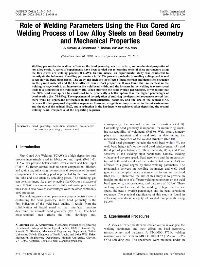
The bead-on-plate technique was used to perform theexperiments as shown in Fig. 1(a). The parent material and thetubular welding wire used in this study were, respectively, low-carbon steel (AS 3678-250) and Super-COR 5 (conforming toAWS A5.20). The chemical composition and mechanicalproperties of both the parent material and consumable weldmetal are shown in Tables 1 and 2, respectively.
2.2 Welding Parameters and Bead Geometry
Four welding traverse speeds (360, 420, 480, and 540 mm/min) with respective welding voltages (23, 25, 28, and 32 V)were employed using a tubular welding wire of 1.2 mmdiameter. The plate was then left to cool down to ambienttemperature. A coupon of 10 mm width was taken fromthe center of each specimen as shown in Fig. 1(a) and (b).The welding voltage and amperage were recorded during thewelding process. Three samples were produced for eachtraverse speed and voltage to ensure repeatability. A wire-feeding rate of 3600 mm/min was used. Figure 1(b) shows the
weld bead geometry elements: weld bead width (W), weld beadheight (H), depth of penetration (P) and depth of HAZ(DHAZ). These elements were measured, and then wereaveraged for the three samples. Specimens were polished andetched using a 2% nital solution to reveal the microstructureand display the bead dimensions. Measurements of beaddimensions were carried out using a binocular microscopeequipped with a calibrated reticule.
2.3 Percentage of Bead Overlap
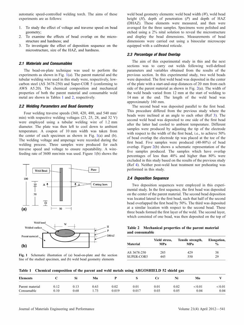
The aim of this experimental study in this and the nextsections was to carry out welds following well-definedparameters and variables obtained from the results of theprevious section. In this experimental study, two weld beadswere deposited. The first weld bead was deposited in the centerof the plate with a start-and-stop distances of 20 mm from eachside of the parent material as shown in Fig. 2(a). The width ofthe weld beads varied from 12 mm at the start of welding to14 mm at the end. The length of the weld bead wasapproximately 160 mm.
The second bead was deposited parallel to the first bead.This procedure differed from the previous study where thebeads were inclined at an angle to each other (Ref 3). Thesecond weld bead was deposited to one side of the first beadafter the latter had cooled to ambient temperature. Differentsamples were produced by adjusting the tip of the electrodewith respect to the width of the first bead, i.e., to achieve 50%of bead overlap the electrode tip was placed at the toe of thefirst bead. Five samples were produced (40-80%) of beadoverlap. Figure 2(b) shows a schematic representation of thefive samples produced. The samples which have overlappercentages of less than 40% and higher than 80% wereexcluded in this study based on the results of the previous study(Ref 4). Neither post-weld heat treatment nor preheating wasperformed in this study.
2.4 Deposition Sequence
Two deposition sequences were employed in this experi-mental study. In the first sequence, the first bead was depositedon the center of the parent material. The second bead depositionwas located lateral to the first bead, such that half of the secondbead overlapped the first bead by 50%. The third was depositedat a similar location with respect to the second bead. Thesethree beads formed the first layer of the weld. The second layer,which consisted of one bead, was then deposited on the top of
Fig. 1 Schematic illustration of (a) bead-on-plate and the sectionline of the studied specimen, and (b) weld bead geometry elements
Table 1 Chemical composition of the parent and weld metals using ARGOSHIELD 52 shield gas
Elements C Si Mn P S Cr Ni Mo V
Parent material 0.12 0.13 0.63 0.02 0.01 0.01 0.02 <0.01 <0.01Consumable 0.10 0.68 1.73 0.019 0.017 0.03 0.05 0.04 0.04
Table 2 Mechanical properties of the parent materialand consumable
MaterialYield stress,
MPaTensile strength,
MPaElongation,
%
AS 3678-250 285 429 38SUPER-COR5 445 550 29
Journal of Materials Engineering and Performance Volume 21(4) April 2012—541
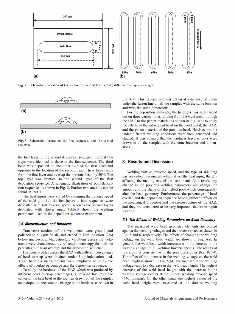
the first layer. In the second deposition sequence, the first twosteps were identical to those in the first sequence. The thirdbead was deposited on the other side of the first bead andopposite to the location of the second bead. These three beadsform the first layer and overlap the previous bead by 50%. Thetop layer was identical to the second layer of the firstdeposition sequence. A schematic illustration of both deposi-tion sequences is shown in Fig. 3. Further explanations can befound in Ref 5.
The heat inputs were varied by changing the traverse speedof the weld gun, i.e., the first layers in both sequences weredeposited with fast traverse speed, whereas the second layersdeposited with slower ones. Table 3 shows the weldingparameters used in the deposition sequence experiment.
2.5 Microstructure and Hardness
Transverse sections of the weldments were ground andpolished to a 3 lm finish, and etched in Nital solution (2%)before microscopy. Microstructure variations across the weld-ments were characterized by reflected microscopy for both thepercentage of bead overlap and the deposition sequence.
Hardness profiles across the HAZ with different percentagesof bead overlap were obtained under 5 kg indentation load.These hardness measurements were employed to study theeffects of overlap percentage and the deposition sequence.
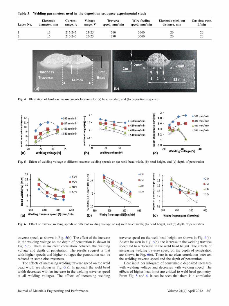
To study the hardness of the HAZ which was produced bydifferent bead overlap percentages, a traverse line from thecenter of the first bead to the toe was drawn on all the samplesand adopted to measure the change in the hardness as shown in
Fig. 4(a). This traverse line was drawn at a distance of 1 mmunder the fusion line on all the samples with the same locationand with the same dimensions.
For the deposition sequence, the hardness was also carriedout on three vertical lines moving from the weld metal throughthe HAZ to the parent material as shown in Fig. 4(b) to studythe effects of the subsequent bead on the weld metal, the HAZ,and the parent material of the previous bead. Hardness profileunder different welding conditions were then generated andstudied. It was ensured that the hardness traverse lines weredrawn in all the samples with the same location and dimen-sions.
3. Results and Discussion
Welding voltage, traverse speed, and the type of shieldinggas are critical parameters which affect the heat input, therebyaffecting the melting rate of the base metal. As a result, anychange in the previous welding parameters will change theamount and the shape of the melted pool which consequentlyalter the bead geometry. Furthermore, the percentage of beadoverlap and the deposition sequence have significant effects onthe mechanical properties and the microstructure of the HAZ,and they are considered to be very important factors in repairwelding.
3.1 The Effects of Welding Parameters on Bead Geometry
The measured weld bead geometry elements are plottedagainst the welding voltages and the traverse speed as shown inFig. 5 and 6, respectively. The effects of changing the weldingvoltage on the weld bead width are shown in Fig. 5(a). Ingeneral, the weld bead width increases with the increase in thewelding voltage, at all welding traverse speeds. The results ofthis study is consistent with the previous studies (Ref 9, 14).The effect of the increase in the welding voltage on the weldbead height is shown in Fig. 5(b). The increase in the weldingvoltage leads to a decrease in the weld bead height. The highestdecrease of the weld bead height with the increase in thewelding voltage occurs at the highest welding traverse speed(540 mm/min). On the other hand, the highest values of theweld bead height were measured at the slowest welding
Fig. 2 Schematic illustration of (a) position of the first bead and (b) different overlap percentages
1 2 4
3
1 3 4 2
(a)
(b)
Fig. 3 Schematic illustration: (a) first sequence, and (b) secondsequence
542—Volume 21(4) April 2012 Journal of Materials Engineering and Performance
traverse speed, as shown in Fig. 5(b). The effect of the increasein the welding voltage on the depth of penetration is shown inFig. 5(c). There is no clear correlation between the weldingvoltage and depth of penetration. The results suggest is thatwith higher speeds and higher voltages the penetration can bereduced in some circumstances.
The effects of increasing welding traverse speed on the weldbead width are shown in Fig. 6(a). In general, the weld beadwidth decreases with an increase in the welding traverse speedat all welding voltages. The effects of increasing welding
traverse speed on the weld bead height are shown in Fig. 6(b).As can be seen in Fig. 6(b), the increase in the welding traversespeed led to a decrease in the weld bead height. The effects ofincreasing welding traverse speed on the depth of penetrationare shown in Fig. 6(c). There is no clear correlation betweenthe welding traverse speed and the depth of penetration.
Heat input per kilogram of consumable deposited increaseswith welding voltage and decreases with welding speed. Theeffects of higher heat input are critical to weld bead geometry.From Fig. 5 and 6, it can be seen that there is a correlation
Table 3 Welding parameters used in the deposition sequence experimental study
Layer No.Electrode
diameter, mmCurrentrange, A
Voltagerange, V
Traversespeed, mm/min
Wire feedingspeed, mm/min
Electrode stick-outdistance, mm
Gas flow rate,L/min
1 1.6 215-245 23-25 560 3600 20 202 1.6 215-245 23-25 290 3600 20 20
Fig. 4 Illustration of hardness measurements locations for (a) bead overlap, and (b) deposition sequence
Fig. 5 Effect of welding voltage at different traverse welding speeds on (a) weld bead width, (b) bead height, and (c) depth of penetration
Fig. 6 Effect of traverse welding speeds at different welding voltage on (a) weld bead width, (b) bead height, and (c) depth of penetration
Journal of Materials Engineering and Performance Volume 21(4) April 2012—543
between the heat input and both the weld bead width andheight. The increase in the welding heat input leads to anincrease in the melted volume under the weld arc and therebyresults in an increase in the width and a decrease in the heightof the weld pool. However, the depth of penetration does notshow a clear trend and penetration at high voltages and weldspeed is reduced.
3.2 The Effects of Bead Overlap Percentage
Different percentages of bead overlaps were studied toexamine their effects on the mechanical properties as well asthe microstructure of the HAZ. In industry, welding repairs tendto be performed using 50% bead overlap, and it is usuallyachieved by placing the tip of the electrode on the toe of theprevious bead (Ref 4). However, there is little research on thejustification and validation for the use of this percentage ofbead overlap. In this study, the parallel deposition method wasused to produce quantitative results with 40-80% overlap asshown in Fig. 2(b). The parallel deposition method used wasalso to be compared with the results of previous study wherethe two beads were inclined at an angle to each other and thusvarying in percentage overlap (Ref 4). All the samples in thisexperimental study consisted of two weld beads only. Sectionsof each percentage of bead overlap were examined to assess thedegree of microstructure tempering in the HAZ and to carry outhardness survey.
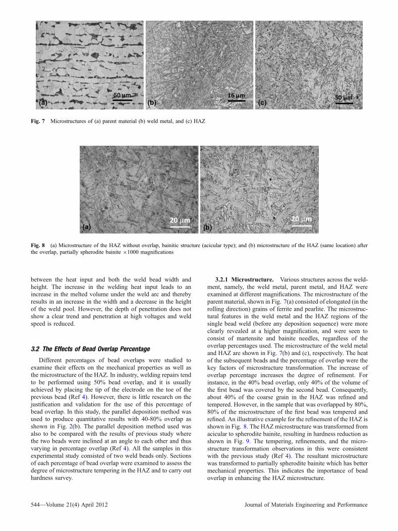
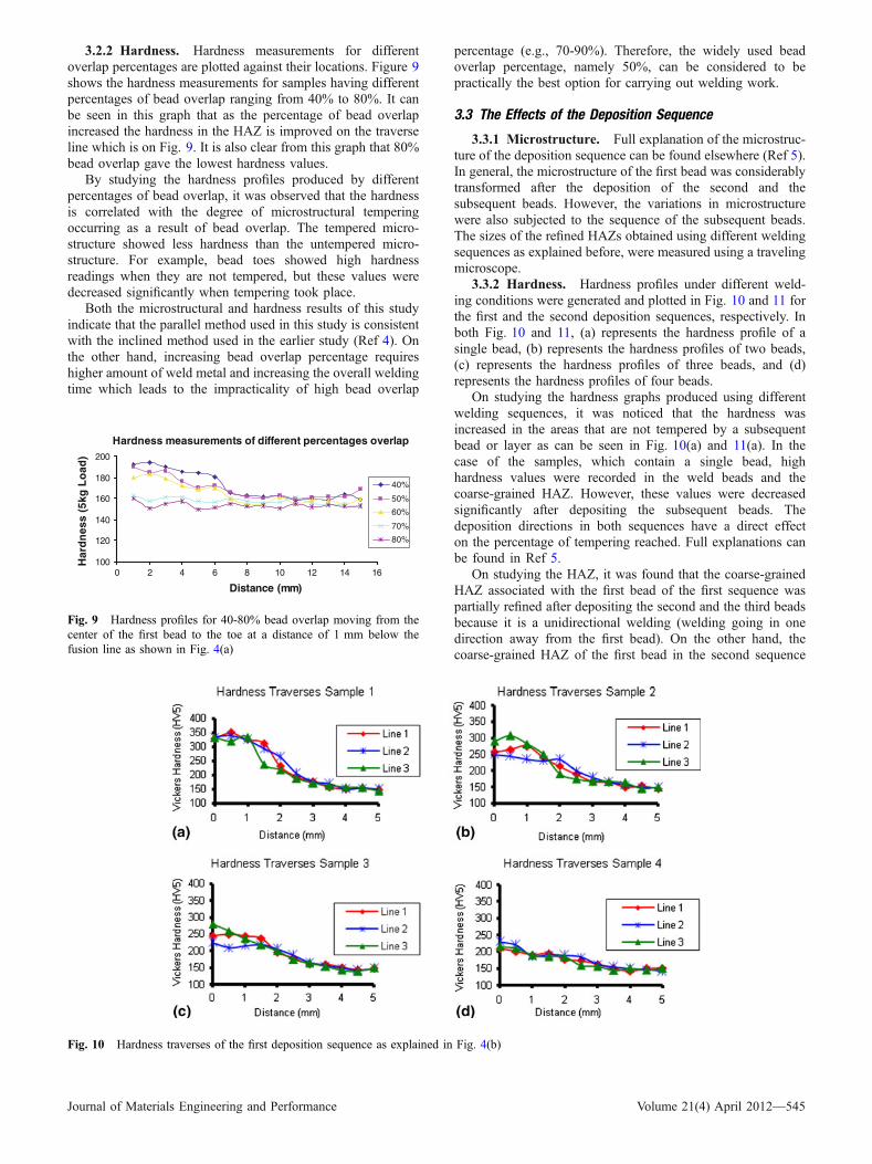
3.2.1 Microstructure. Various structures across the weld-ment, namely, the weld metal, parent metal, and HAZ wereexamined at different magnifications. The microstructure of theparent material, shown in Fig. 7(a) consisted of elongated (in therolling direction) grains of ferrite and pearlite. The microstruc-tural features in the weld metal and the HAZ regions of thesingle bead weld (before any deposition sequence) were moreclearly revealed at a higher magnification, and were seen toconsist of martensite and bainite needles, regardless of theoverlap percentages used. The microstructure of the weld metaland HAZ are shown in Fig. 7(b) and (c), respectively. The heatof the subsequent beads and the percentage of overlap were thekey factors of microstructure transformation. The increase ofoverlap percentage increases the degree of refinement. Forinstance, in the 40% bead overlap, only 40% of the volume ofthe first bead was covered by the second bead. Consequently,about 40% of the coarse grain in the HAZ was refined andtempered. However, in the sample that was overlapped by 80%,80% of the microstructure of the first bead was tempered andrefined. An illustrative example for the refinement of the HAZ isshown in Fig. 8. The HAZ microstructure was transformed fromacicular to spherodite bainite, resulting in hardness reduction asshown in Fig. 9. The tempering, refinements, and the micro-structure transformation observations in this were consistentwith the previous study (Ref 4). The resultant microstructurewas transformed to partially spherodite bainite which has bettermechanical properties. This indicates the importance of beadoverlap in enhancing the HAZ microstructure.
Fig. 7 Microstructures of (a) parent material (b) weld metal, and (c) HAZ
Fig. 8 (a) Microstructure of the HAZ without overlap, bainitic structure (acicular type); and (b) microstructure of the HAZ (same location) afterthe overlap, partially spherodite bainite 91000 magnifications
544—Volume 21(4) April 2012 Journal of Materials Engineering and Performance
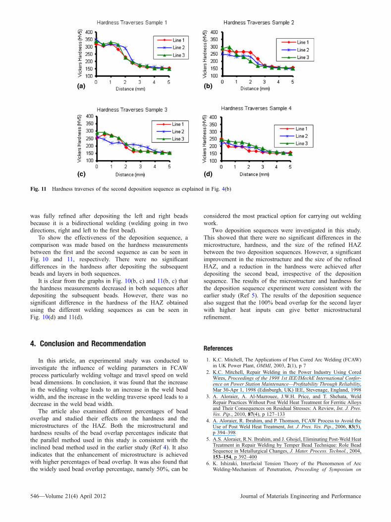
3.2.2 Hardness. Hardness measurements for differentoverlap percentages are plotted against their locations. Figure 9shows the hardness measurements for samples having differentpercentages of bead overlap ranging from 40% to 80%. It canbe seen in this graph that as the percentage of bead overlapincreased the hardness in the HAZ is improved on the traverseline which is on Fig. 9. It is also clear from this graph that 80%bead overlap gave the lowest hardness values.
By studying the hardness profiles produced by differentpercentages of bead overlap, it was observed that the hardnessis correlated with the degree of microstructural temperingoccurring as a result of bead overlap. The tempered micro-structure showed less hardness than the untempered micro-structure. For example, bead toes showed high hardnessreadings when they are not tempered, but these values weredecreased significantly when tempering took place.
Both the microstructural and hardness results of this studyindicate that the parallel method used in this study is consistentwith the inclined method used in the earlier study (Ref 4). Onthe other hand, increasing bead overlap percentage requireshigher amount of weld metal and increasing the overall weldingtime which leads to the impracticality of high bead overlap
percentage (e.g., 70-90%). Therefore, the widely used beadoverlap percentage, namely 50%, can be considered to bepractically the best option for carrying out welding work.
3.3 The Effects of the Deposition Sequence
3.3.1 Microstructure. Full explanation of the microstruc-ture of the deposition sequence can be found elsewhere (Ref 5).In general, the microstructure of the first bead was considerablytransformed after the deposition of the second and thesubsequent beads. However, the variations in microstructurewere also subjected to the sequence of the subsequent beads.The sizes of the refined HAZs obtained using different weldingsequences as explained before, were measured using a travelingmicroscope.
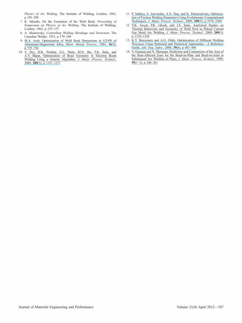
3.3.2 Hardness. Hardness profiles under different weld-ing conditions were generated and plotted in Fig. 10 and 11 forthe first and the second deposition sequences, respectively. Inboth Fig. 10 and 11, (a) represents the hardness profile of asingle bead, (b) represents the hardness profiles of two beads,(c) represents the hardness profiles of three beads, and (d)represents the hardness profiles of four beads.
On studying the hardness graphs produced using differentwelding sequences, it was noticed that the hardness wasincreased in the areas that are not tempered by a subsequentbead or layer as can be seen in Fig. 10(a) and 11(a). In thecase of the samples, which contain a single bead, highhardness values were recorded in the weld beads and thecoarse-grained HAZ. However, these values were decreasedsignificantly after depositing the subsequent beads. Thedeposition directions in both sequences have a direct effecton the percentage of tempering reached. Full explanations canbe found in Ref 5.
On studying the HAZ, it was found that the coarse-grainedHAZ associated with the first bead of the first sequence waspartially refined after depositing the second and the third beadsbecause it is a unidirectional welding (welding going in onedirection away from the first bead). On the other hand, thecoarse-grained HAZ of the first bead in the second sequence
Hardness measurements of different percentages overlap
100
120
140
160
180
200
0 2 4 6 8 10 12 14 16
Distance (mm)
Har
dn
ess
(5kg
Lo
ad)
40%
50%
60%
70%
80%
Fig. 9 Hardness profiles for 40-80% bead overlap moving from thecenter of the first bead to the toe at a distance of 1 mm below thefusion line as shown in Fig. 4(a)
Fig. 10 Hardness traverses of the first deposition sequence as explained in Fig. 4(b)
Journal of Materials Engineering and Performance Volume 21(4) April 2012—545
was fully refined after depositing the left and right beadsbecause it is a bidirectional welding (welding going in twodirections, right and left to the first bead).
To show the effectiveness of the deposition sequence, acomparison was made based on the hardness measurementsbetween the first and the second sequence as can be seen inFig. 10 and 11, respectively. There were no significantdifferences in the hardness after depositing the subsequentbeads and layers in both sequences.
It is clear from the graphs in Fig. 10(b, c) and 11(b, c) thatthe hardness measurements decreased in both sequences afterdepositing the subsequent beads. However, there was nosignificant difference in the hardness of the HAZ obtainedusing the different welding sequences as can be seen inFig. 10(d) and 11(d).
4. Conclusion and Recommendation
In this article, an experimental study was conducted toinvestigate the influence of welding parameters in FCAWprocess particularly welding voltage and travel speed on weldbead dimensions. In conclusion, it was found that the increasein the welding voltage leads to an increase in the weld beadwidth, and the increase in the welding traverse speed leads to adecrease in the weld bead width.
The article also examined different percentages of beadoverlap and studied their effects on the hardness and themicrostructures of the HAZ. Both the microstructural andhardness results of the bead overlap percentages indicate thatthe parallel method used in this study is consistent with theinclined bead method used in the earlier study (Ref 4). It alsoindicates that the enhancement of microstructure is achievedwith higher percentages of bead overlap. It was also found thatthe widely used bead overlap percentage, namely 50%, can be
considered the most practical option for carrying out weldingwork.
Two deposition sequences were investigated in this study.This showed that there were no significant differences in themicrostructure, hardness, and the size of the refined HAZbetween the two deposition sequences. However, a significantimprovement in the microstructure and the size of the refinedHAZ, and a reduction in the hardness were achieved afterdepositing the second bead, irrespective of the depositionsequence. The results of the microstructure and hardness forthe deposition sequence experiment were consistent with theearlier study (Ref 5). The results of the deposition sequencealso suggest that the 100% bead overlap for the second layerwith higher heat inputs can give better microstructuralrefinement.
References
1. K.C. Mitchell, The Applications of Flux Cored Arc Welding (FCAW)in UK Power Plant, OMMI, 2003, 2(1), p 7
2. K.C. Mitchell, Repair Welding in the Power Industry Using CoredWires, Proceedings of the 1998 1st IEE/IMechE International Confer-ence on Power Station Maintenance—Profitability Through Reliability,Mar 30-Apr 1, 1998 (Edinburgh, UK) IEE, Stevenage, England, 1998
3. A. Aloraier, A. Al-Mazrouee, J.W.H. Price, and T. Shehata, WeldRepair Practices Without Post Weld Heat Treatment for Ferritic Alloysand Their Consequences on Residual Stresses: A Review, Int. J. Pres.Ves. Pip., 2010, 87(4), p 127–133
4. A. Aloraier, R. Ibrahim, and P. Thomson, FCAW Process to Avoid theUse of Post Weld Heat Treatment, Int. J. Pres. Ves. Pip., 2006, 83(5),p 394–398
5. A.S. Aloraier, R.N. Ibrahim, and J. Ghojel, Eliminating Post-Weld HeatTreatment in Repair Welding by Temper Bead Technique: Role BeadSequence in Metallurgical Changes, J. Mater. Process. Technol., 2004,153–154, p 392–400
6. K. Ishizaki, Interfacial Tension Theory of the Phenomenon of ArcWelding-Mechanism of Penetration, Proceeding of Symposium on
Fig. 11 Hardness traverses of the second deposition sequence as explained in Fig. 4(b)
546—Volume 21(4) April 2012 Journal of Materials Engineering and Performance
Physics of Arc Welding, The Institute of Welding, London, 1962,p 195–209
7. K. Ishizaki, On the Formation of the Weld Bead, Proceeding ofSymposium on Physics of Arc Welding, The Institute of Welding,London, 1962, p 155–157
8. A. Shumovsky, Controlling Welding Shrinkage and Distortion, TheCanadian Welder, 1952, p 179–180
9. M.A. Aesh, Optimization of Weld Bead Dimensions in GTAW ofAluminum-Magnesium Alloy, Mater. Manuf. Process., 2001, 16(5),p 725–736
10. V. Dey, D.K. Pratihar, G.L. Datta, M.N. Jha, T.K. Saha, andA.V. Bapat, Optimization of Bead Geometry in Electron BeamWelding Using a Genetic Algorithm, J. Mater. Process. Technol.,2009, 209(3), p 1151–1157
11. P. Sathiya, S. Aravindan, A.N. Haq, and K. Paneerselvam, Optimiza-tion of Friction Welding Parameters Using Evolutionary ComputationalTechniques, J. Mater. Process. Technol., 2009, 209(5), p 2576–2584
12. V.K. Goyal, P.K. Ghosh, and J.S. Saini, Analytical Studies onThermal Behaviour and Geometry of Weld Pool in Pulsed CurrentGas Metal Arc Welding, J. Mater. Process. Technol., 2009, 209(3),p 1318–1336
13. K.Y. Benyounis and A.G. Olabi, Optimization of Different WeldingProcesses Using Statistical and Numerical Approaches—A ReferenceGuide, Adv. Eng. Softw., 2008, 39(6), p 483–496
14. V. Gunaraj and N. Murugan, Prediction and Comparison of the Area ofthe Heat-Affected Zone for the Bead-on-Plate and Bead-on-Joint inSubmerged Arc Welding of Pipes, J. Mater. Process. Technol., 1999,95(1–3), p 246–261
Journal of Materials Engineering and Performance Volume 21(4) April 2012—547
Related Documents