Welcome message from author
This document is posted to help you gain knowledge. Please leave a comment to let me know what you think about it! Share it to your friends and learn new things together.
Transcript
Risk analysis of islanding ofphotovoltaic power systemswithin low voltage distribution networks
Task VReport IEA-PVPS T5-08: 2002March 2002

IEA PVPS International Energy Agency
Implementing Agreement on Photovoltaic Power Systems
TASK V Grid Interconnection of Building Integrated
and Other Dispersed Photovoltaic Power Systems
Report IEA PVPS T5-08: 2002 RISK ANALYSIS OF ISLANDING OF PHOTOVOLTAIC
POWER SYSTEMS WITHIN LOW VOLTAGE DISTRIBUTION NETWORKS
March 2002
Authors:
Neil Cullen Freelance Consultant
Hillside House Swindon, UK
SN1 3QA.
Jim Thornycroft Halcrow Group Ltd
Burderop Park Swindon, UK
SN4 0QD.
Alan Collinson EA Technology
Capenhurst Technology Park Chester, UK CH1 6ES.
To obtain additional copies of this report or information on other IEA-PVPS publications, contact the IEA website: http://www.iea.org

Risk analysis of islanding of photovoltaic power systems within low voltage distribution networks Page i
CONTENTS FOREWORD................................................................................................................................. II
ABSTRACT AND KEYWORDS................................................................................................. II
EXECUTIVE SUMMARY.......................................................................................................... III
1 INTRODUCTION..................................................................................................................1 1.1 Objectives of the Report.....................................................................................................1
2 PROBABILITY OF ISLANDING.........................................................................................2 2.1 Background ........................................................................................................................2
2.2 The Power Island Zone.......................................................................................................2
2.3 Stability of a Power Island .................................................................................................3 2.4 Load/Generation Match......................................................................................................4
2.5 Loss of Mains Protection and Islanding Detection ............................................................4
3 RISK ASSESSMENT OF ISLANDING USING IEC STD 61508 .......................................5 3.1 Safety Integrity Levels .......................................................................................................6 3.2 PV Risk Analysis ‘Fault Tree’ ...........................................................................................7
4 LV DISTRIBUTION NETWORKS ......................................................................................8 4.1 Types and characteristics of distribution network..............................................................8 4.3 P(LOM) – The Probability of Loss of Mains Supply.........................................................8 4.4 P(Match) – The Probability of Load/Generation Match ....................................................9
5 INVERTER ..........................................................................................................................13 5.1 Inverter Risk Analysis Fault Tree ....................................................................................13 5.2 Protection Failure .............................................................................................................13 5.3 Incorrect Installation.........................................................................................................14 5.4 Islanding Non-Detection Zone (NDZ) .............................................................................14
6 OPERATORS.......................................................................................................................16 6.1 Network Operators ...........................................................................................................16 6.2 Customer ..........................................................................................................................16
7 ISLANDING AND RISK ....................................................................................................17
8 CONCLUSIONS AND RECOMMENDATIONS...............................................................21
REFERENCES................................................................................................................................I
ACKNOWLEDGEMENTS .......................................................................................................... II
APPENDIX A: TABLE OF RELATIVE RISK........................................................................... III
LIST OF IEA PVPS TASK V PARTICIPANTS:........................................................................IV
Risk analysis of islanding of photovoltaic power systems within low voltage distribution networks Page ii
FOREWORD The International Energy Agency (IEA), founded in November 1974, is an autonomous body within the framework of the Organisation for Economic Co-operation and Development (OECD) which carries out a comprehensive programme of energy co-operation among its 22 member countries. The European Commission also participates in the work of the Agency. The IEA Photovoltaic Power Systems Programme (PVPS) is one of the collaborative R&D agreements established within the IEA, and since 1993 its participants have conducted various joint projects on the photovoltaic conversion of solar energy into electricity. The twenty-two members are: Australia, Austria, Canada, Denmark, European Commission, Finland, France, Germany, Israel, Italy, Japan, Korea, Mexico, Netherlands, Norway, Portugal, Spain, Sweden, Switzerland, Turkey, United Kingdom and United States. This report has been prepared under the supervision of PVPS Task V by: Neil Cullen Freelance Consultant Hillside House Swindon, UK SN1 3QA. [email protected] Tel: +44 (0) 1793 345 659
Jim Thornycroft Halcrow Burderop Park Swindon, UK SN4 0QD. [email protected] Tel: +44 (0) 1793 812 479
Alan Collinson EA Technology Capenhurst Technology Park Chester, UK CH6 5SD. [email protected] Tel: +44 (0) 151 347 2396
in co-operation with experts of the following countries: Australia, Austria, Denmark, Germany, Italy, Japan, Netherlands, Portugal, Switzerland, United Kingdom and United States and approved by the Executive Committee of the PVPS programme. The report expresses as accurately as possible the international consensus of opinion on the subjects addressed.
ABSTRACT AND KEYWORDS The purpose of this study was to apply formal risk analysis techniques to the issue of islanding of photovoltaic power systems within low voltage distribution networks. The aim was to perform a first pass calculation to determine the additional level of risk that islanding could present to the safety of customers and network maintenance staff. In the event of a loss of mains supply, grid-connected PV systems are required to automatically disconnect from the grid in order to prevent the network from islanding. This study has identified the reliability required of the islanding detection and control systems and their installation, based on standard procedures for developing a safety assurance strategy. Keywords: Photovoltaics, islanding, risk analysis, probability, safety, low voltage networks,
grid connected, non-detection zone, installation, safety integrity level

Risk analysis of islanding of photovoltaic power systems within low voltage distribution networks Page iii
EXECUTIVE SUMMARY The International Energy Agency (IEA) Implementing Agreement on Photovoltaic Power Systems (PVPS) Task V Working Group is entitled: “Grid Interconnection of Building Integrated and Other Dispersed Photovoltaic Power Systems" and since its formation in 1993 has investigated grid interconnection issues through international collaboration. The main objective was to develop and verify technical requirements which may serve as technical guidelines for grid interconnection of building integrated and other dispersed PV systems. The development of technical guidelines will enable safe and reliable interconnection of PV systems to the utility grid at the lowest possible cost. It is generally accepted that grid interconnection of photovoltaic (PV) power generation systems enables effective utilisation of the generated power from PV. However, technical requirements of both the utility power system grid and the PV system must be satisfied to ensure the safety of the PV operator and the reliability of the utility grid. Clarifying the technical requirements for grid interconnection and solving the problems are therefore very important issues for the widespread application of grid-connected PV systems. The requirements for grid-connected systems are closely related to the configuration and operational regime of the power distribution system, which are often country-specific. However, one of the technical issues of concern that is common to all network operators around the world is that of islanding. The purpose of this study was to apply formal risk analysis techniques to the issue of islanding of photovoltaic power systems within low voltage distribution networks. The aim was to perform a first pass calculation to determine the additional level of risk that islanding could present to the safety of customers and network maintenance staff. In the event of a loss of mains supply, grid-connected PV systems are required to automatically disconnect from the grid in order to prevent the network from islanding. This study has identified the reliability required of the islanding detection and control systems and their installation, based on standard procedures for developing a safety assurance strategy. The main conclusions from the study are: • The “benchmark” risk that already exists for network operators and customers is of the order
of 10-6 per year for an individual person • The risk of electric shock associated with islanding of PV systems under worst-case PV
penetration scenarios to both network operators and customers is typically <10-9 per year • Thus, the additional risk presented by islanding does not materially increase the risk that
already exists as long as the risk is managed properly • Loss of mains (LOM) protection functionality provides additional safety, up to a point:
• An inverter’s designed safety integrity level (SIL) affects the level of risk • The quality of the installation and any subsequent maintenance will also affect the risk
• There is a need to inform and educate both network operators and customers about the implications of the use of PV as an embedded micro-generator, as PV systems become more widespread.

Risk analysis of islanding of photovoltaic power systems within low voltage distribution networks Page iv
It is recommended that: • Since LOM functionality is included in many PV inverters already, it is appropriate to
maintain this requirement, but emphasis should be put on simple, robust, verifiable and cost-effective solutions (e.g: software-based).
• The findings of this report should be:
i) incorporated into the training and education programmes of network operators and PV system installers
ii) reviewed by appropriate interconnection standards working groups
iii) publicised in appropriate professional institutional journals and subjected to thorough public peer review

Risk analysis of islanding of photovoltaic power systems within low voltage distribution networks Page 1
1 INTRODUCTION Task V is a technical working group of the International Energy Agency (IEA), Implementing Agreement on Photovoltaic Power Systems (PVPS). The title of the working group is “Grid Interconnection of Building Integrated and Other Dispersed Photovoltaic Power Systems.” The main objective of Task V is to develop and verify technical requirements that may serve as technical guidelines for the network interconnection of building-integrated and other dispersed photovoltaic (PV) systems. These technical guidelines are intended to ensure the safe, reliable and low-cost interconnection of PV systems to the electric power network. It is generally accepted that grid interconnection of photovoltaic (PV) power generation systems enables effective utilisation of the generated power from PV. However, technical requirements of both the utility power system grid and the PV system must be satisfied to ensure the safety of the PV operator and the reliability of the utility grid [1]. Clarifying the technical requirements for grid interconnection and solving the problems are therefore very important issues for the widespread application of grid-connected PV systems. The requirements for grid-connected systems are closely related to the configuration and operational regime of the power distribution system, which are often country-specific [2]. However, one of the technical issues of concern that is common to all network operators around the world is that of unintentional power islands, commonly referred to as islanding [3]. This phenomenon is common to all embedded generation and not just PV. It is the role of distribution network operators to provide a reliable, secure and safe power network that meets certain performance criteria and at a reasonable cost to its customers. Traditionally, these customers have been almost exclusively “demand” customers. However, the general liberalisation of the electricity industry which is taking place globally means that small generators now have certain rights to connect their generators to the distribution network in many countries. This right normally has to be balanced by the costs associated with connection. The occurrence of unintentional power islands within distribution networks is of major concern to network operators. Islanding impacts on many of the operational and safety requirements of networks to both network maintenance operations and customers and therefore network operators are keen to ensure that islanding cannot occur.
1.1 Objectives of the Report The purpose of this study was to apply formal risk analysis techniques to the issue of islanding of photovoltaic power systems within low voltage distribution networks. The aim was to perform a first pass calculation to determine the additional level of risk that islanding could present to the safety of customers and network maintenance staff. In the event of a loss of mains supply, grid-connected PV systems are required to automatically disconnect from the grid in order to prevent the network from islanding. This study has identified the reliability required of the islanding detection and control systems and their installation, based on standard procedures for developing a safety assurance strategy. In addition to design issues, the study outlines other issues which must be included in system assessment, approval and management in order to ensure adequate safety.

Risk analysis of islanding of photovoltaic power systems within low voltage distribution networks Page 2
2 PROBABILITY OF ISLANDING
2.1 Background Islanding of inverter-connected PV-generator systems means “… any situation where the source of power from the network operator’s distribution system is disconnected from the network section in which the generator is connected, and one or more inverters maintain a supply to that section of the distribution system or consumer’s installation” [4]. Thus, in the event of a loss of mains supply, grid-connected PV systems are required to automatically disconnect from the grid in order to prevent the power network from islanding. Many techniques, using either active or passive detection methods, have been developed over the years. A comprehensive review of loss of mains detection techniques is contained in a complementary IEA report [5]. This study has considered the risk of islanding to operators as a combination of the probability of load/generation match combined with the simultaneous loss of mains supply and the failure of the protection to detect the island on demand, i.e. • Risk(islanding) = P(match) * P(LOM) * P(protection failure) [2.1] The probability of the loss of mains supply, P(LOM), can be estimated reasonably accurately from existing data. In this study, actual data relating to the probability of power outage in typical UK distribution systems is used in conjunction with estimates for the frequency of maintenance operations carried out by network maintenance staff. However, the probability of load/generation match, P(match) is harder to define, therefore more information is needed. This information has been provided by a parallel study carried out as part of the co-ordinated IEA PVPS Task V activities in the form of a comprehensive Dutch study examining probability of load/generation match [6]. The third component in the risk analysis is the failure of the protection. The probability of the protection failing to detect an island is a function of several factors:
• the islanding detection method (e.g. non-detection zone), • the inverter designed safety integrity level (SIL), as well as • the quality of the installation.
Before examining the risk analysis of islanding in detail, it is important to answer some fundamental questions, such as:
• what is the boundary for a power island? • how long does islanding have to occur to be a problem? • how close a match between load & generation is needed to produce an island? • how can an inverter reduce the risk of islanding occurring to an appropriate level?
2.2 The Power Island Zone Given the definition of islanding above, power island zones could exist within any of the domains illustrated in Figure 1, ranging from a single house to a whole section of network up to

Risk analysis of islanding of photovoltaic power systems within low voltage distribution networks Page 3 the distribution transformer and including a single phase or multiple phases.
Figure 1: Potential Power Island Zones
However, the boundary for an island is likely to conform to the following constraints: i) occur under no-fault conditions ii) every switch/fuse/breaker forms a possible boundary iii) a ‘single house’ island would not normally concern network operators, since the public
network is not energised, and therefore will not affect network maintenance staff. However, network operators do have a ‘duty of care’ towards their customers to ensure adequate provisions for their safe use of the network and so some consideration is required of a power island consisting of a single house.
Under these constraints, the most likely island boundary on the public network will be at the distribution transformer fuse (LV side or MV side). For a single house, the most likely island boundary is at the consumer unit (e.g. cut-out fuse, MCB or main switch).
2.3 Stability of a Power Island The stability of a power island is governed by how long it is able to sustain itself. For the purposes of this study we define three states of island stability: i) unstable island – an island condition that lasts for less than 5 seconds ii) quasi-stable island – an island condition that lasts for 5 to 60 seconds iii) stable island – an island condition lasting longer than 60 seconds In this study, it is assumed that unstable islands (i.e. islands lasting < 5 seconds) do not present a significant risk, since there is a natural human response time delay between disconnecting an electrical circuit and performing any manual work on the disconnected circuit. Similarly, the results of the Dutch study has shown that islanding conditions are unlikely to persist for >60 seconds and so islands of duration longer than one minute are also not considered in order to simplify the analysis.

Risk analysis of islanding of photovoltaic power systems within low voltage distribution networks Page 4 Thus, data related to “quasi-stable” islands has been extracted from the Dutch data for the purposes of this study.
2.4 Load/Generation Match The probability of load/generation match conditions being met at any time is a function of the load/generation match criteria. The match criteria depends on the degree of closeness required to be considered as “matched”. It also depends on the parameters that need to be considered to be matched, such as load/generation current, real power and reactive power.
2.5 Loss of Mains Protection and Islanding Detection The risks associated with islanding can be reduced if the inverter has the ability to detect a loss of mains supply. Many islanding detection methods have been developed, where each method has its own inherent strengths and weaknesses. However, the detection of a loss of mains supply can never be absolute. For example, many of the detection methods have a “non-detection zone” (NDZ), where under certain conditions the loss of mains supply cannot be detected. In practice, designers strive to make the NDZ as small as practically possible. There are other factors that also limit the practical ability of the protection to detect loss of mains. These include the inherent designed safety integrity level (SIL) of the inverter and also the installation and commissioning procedures for the PV inverter system.
Risk analysis of islanding of photovoltaic power systems within low voltage distribution networks Page 5
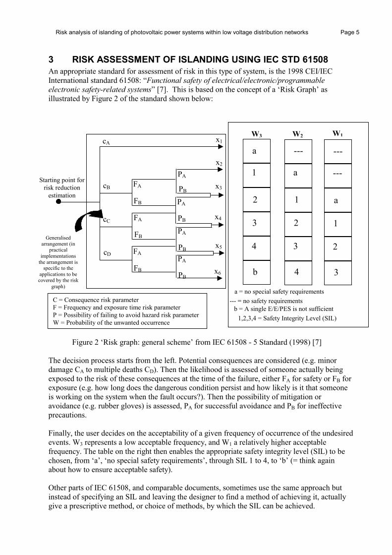
3 RISK ASSESSMENT OF ISLANDING USING IEC STD 61508 An appropriate standard for assessment of risk in this type of system, is the 1998 CEI/IEC International standard 61508: “Functional safety of electrical/electronic/programmable electronic safety-related systems” [7]. This is based on the concept of a ‘Risk Graph’ as illustrated by Figure 2 of the standard shown below:
Figure 2 ‘Risk graph: general scheme’ from IEC 61508 - 5 Standard (1998) [7]
The decision process starts from the left. Potential consequences are considered (e.g. minor damage CA to multiple deaths CD). Then the likelihood is assessed of someone actually being exposed to the risk of these consequences at the time of the failure, either FA for safety or FB for exposure (e.g. how long does the dangerous condition persist and how likely is it that someone is working on the system when the fault occurs?). Then the possibility of mitigation or avoidance (e.g. rubber gloves) is assessed, PA for successful avoidance and PB for ineffective precautions. Finally, the user decides on the acceptability of a given frequency of occurrence of the undesired events. W3 represents a low acceptable frequency, and W1 a relatively higher acceptable frequency. The table on the right then enables the appropriate safety integrity level (SIL) to be chosen, from ‘a’, ‘no special safety requirements’, through SIL 1 to 4, to ‘b’ (= think again about how to ensure acceptable safety). Other parts of IEC 61508, and comparable documents, sometimes use the same approach but instead of specifying an SIL and leaving the designer to find a method of achieving it, actually give a prescriptive method, or choice of methods, by which the SIL can be achieved.
Generalised arrangement (in
practical implementations
the arrangement is specific to the
applications to be covered by the risk
graph)
a
b
1
3
2
4
---
4
a
2
1
3
---
3
---
1
a
2
--- = no safety requirements a = no special safety requirements
b = A single E/E/PES is not sufficient 1,2,3,4 = Safety Integrity Level (SIL)
W3 W2 W1x1
x2
x3
x4
x5
x6
cA
cB
cC
cD
FA
FB
FA
FB
FA
FB
PA
PB
PA
PB
PA
PB
PA
PB
Starting point for risk reduction
estimation
C = Consequence risk parameter F = Frequency and exposure time risk parameter P = Possibility of failing to avoid hazard risk parameter W = Probability of the unwanted occurrence
Risk analysis of islanding of photovoltaic power systems within low voltage distribution networks Page 6
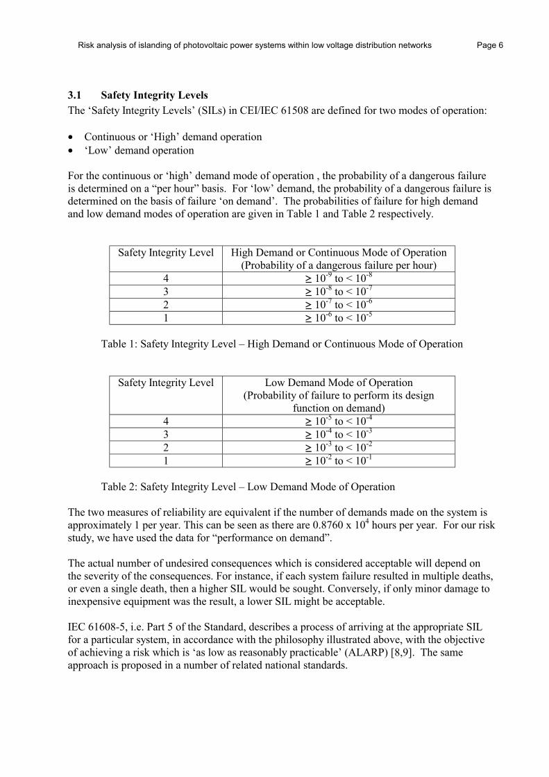
3.1 Safety Integrity Levels The ‘Safety Integrity Levels’ (SILs) in CEI/IEC 61508 are defined for two modes of operation: • Continuous or ‘High’ demand operation • ‘Low’ demand operation For the continuous or ‘high’ demand mode of operation , the probability of a dangerous failure is determined on a “per hour” basis. For ‘low’ demand, the probability of a dangerous failure is determined on the basis of failure ‘on demand’. The probabilities of failure for high demand and low demand modes of operation are given in Table 1 and Table 2 respectively.
Safety Integrity Level High Demand or Continuous Mode of Operation (Probability of a dangerous failure per hour)
4 ≥ 10-9 to < 10-8 3 ≥ 10-8 to < 10-7 2 ≥ 10-7 to < 10-6 1 ≥ 10-6 to < 10-5
Table 1: Safety Integrity Level – High Demand or Continuous Mode of Operation
Safety Integrity Level Low Demand Mode of Operation (Probability of failure to perform its design
function on demand) 4 ≥ 10-5 to < 10-4 3 ≥ 10-4 to < 10-3 2 ≥ 10-3 to < 10-2 1 ≥ 10-2 to < 10-1
Table 2: Safety Integrity Level – Low Demand Mode of Operation
The two measures of reliability are equivalent if the number of demands made on the system is approximately 1 per year. This can be seen as there are 0.8760 x 10⁴ hours per year. For our risk study, we have used the data for “performance on demand”. The actual number of undesired consequences which is considered acceptable will depend on the severity of the consequences. For instance, if each system failure resulted in multiple deaths, or even a single death, then a higher SIL would be sought. Conversely, if only minor damage to inexpensive equipment was the result, a lower SIL might be acceptable. IEC 61608-5, i.e. Part 5 of the Standard, describes a process of arriving at the appropriate SIL for a particular system, in accordance with the philosophy illustrated above, with the objective of achieving a risk which is ‘as low as reasonably practicable’ (ALARP) [8,9]. The same approach is proposed in a number of related national standards.

Risk analysis of islanding of photovoltaic power systems within low voltage distribution networks Page 7 3.2 PV Risk Analysis ‘Fault Tree’ The ‘fault tree’ method used to structure the PV risk analysis in this study is based on the IEC 61805 risk graph methodology. In this case we are initially able to consider the distribution network and the PV inverter separately to identify the potential for islanding and then assess how this impacts on the risk to operators (i.e. network operator maintenance staff and domestic customers). This methodology is illustrated in Figure 3.
Figure 3: PV Islanding Risk Analysis Fault Tree
• Network – load/generation match and loss of mains supply • Inverter – inverter protection does not detect loss of mains • Operator – operator touches conductor
Figure 3 indicates that for an island to occur there has to be a match between load and generation at the same time as a loss of mains supply occurs. Furthermore, the inverter protection must fail to detect the loss of mains condition. Finally, for an operator to be at risk, he must touch the energised live conductor. Each of the elements of the fault tree are examined in more detail in the following sections. Section 4 gives individual consideration to distribution networks, Section 5 examines the inverter aspects and Section 6 looks at the operator issues. The three elements are then brought together in the full risk analysis in Section 7.
AND
NETWORK
INVERTER
ISLANDING
RISK
AND
OPERATOR
Risk analysis of islanding of photovoltaic power systems within low voltage distribution networks Page 8
4 LV DISTRIBUTION NETWORKS This section is based on UK network data as this information was most readily available for this ‘first pass’ calculation.
4.1 Types and characteristics of distribution network The UK uses a mixture of overhead lines and underground cables to supply customers at low voltages (i.e. 230 volts). Typically, overhead line networks have slightly different characteristics to cable networks (in terms of fault levels, types of fault {earth fault, phase-to-phase fault, etc.} and numbers of faults per customer and duration of fault/outage). The majority of LV networks in the UK are cable rather than overhead line (approximately 80% of the UK’s LV network is cable network, measured by distance). As one might expect, LV cable networks typically have higher customer densities (approximately 85 customers per km of cable) compared with LV overhead line networks (approximately 22 customers per km of overhead line). This means that approx 95% of LV domestic customers are supplied by LV cable, leaving 5% of domestic customers supplied by LV overhead line. The fault rate for overhead line customers is likely to be higher – say two supply interruptions per year, against cable customers with typically less than one supply interruption every five years. Note that the fault rates are not directly applicable to islanding, since a short circuit fault should mean that the inverter’s overcurrent protection should operate (i.e. does not have to rely on island detection). However, fault rate can be used as a proxy to indicate the level of maintenance activity on the network, requiring re-configuration of other sections of the network where no fault exists, resulting in the potential for loss of supply to other parts of the network. 4.2 Probability of a power island The probability of a power island can be split into two separate, independent events which need to occur at the same time, as described previously. These are: i) P(LOM) - the network zone becomes disconnected from the main network ii) P(match) - the simultaneous match of load and generation within a network zone
4.3 P(LOM) – The Probability of Loss of Mains Supply If an approximate value for the potential “exposure rate” for domestic customers is estimated using network fault rates as a proxy, we have: • 2 faults per year for a rural overhead line network, leading to a customer exposure rate of 2/(days*hours*minutes*seconds) per second where
days = days in a year hours = hours in a day minutes = minutes in an hour seconds = seconds in a minute
= 2/(365*24*60*60) = 6.34 x 10⁻⁸ per second [4.1]
Risk analysis of islanding of photovoltaic power systems within low voltage distribution networks Page 9 • 0.2 faults per year for a urban cable network leads to a customer exposure rate of 0.2/(days*hours*minutes*seconds) per second
= 0.2/(365*24*60*60) = 6.34 x 10⁻⁹ per second [4.2] For network maintenance staff, if a working year is divided into 250 working days and each day has two ‘jobs’, each with four switching operations, then a maintenance engineer performs 2000 switching operations per year. Thus, if an approximate value for the potential “exposure rate” for network maintenance staff can be estimated on this basis, we have: • 2000 switching operations per year leads to a network maintenance staff exposure rate of 2000/(days*hours*minutes*seconds) per second where
days = working days in a year hours = working hours in a day minutes = minutes in an hour seconds = seconds in a minute
= 2000/(250*8*60*60) = 2.78x10⁻⁴ per second [4.3] These values will be used in the Risk Calculation carried out in Section 7.
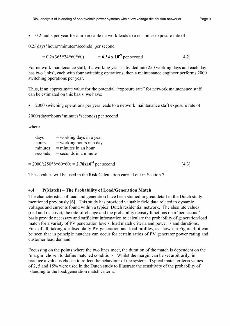
4.4 P(Match) – The Probability of Load/Generation Match The characteristics of load and generation have been studied in great detail in the Dutch study mentioned previously [6]. This study has provided valuable field data related to dynamic voltages and currents found within a typical Dutch residential network. The absolute values (real and reactive), the rate-of-change and the probability density functions on a ‘per second’ basis provide necessary and sufficient information to calculate the probability of generation/load match for a variety of PV penetration levels, load match criteria and power island durations. First of all, taking idealised daily PV generation and load profiles, as shown in Figure 4, it can be seen that in principle matches can occur for certain ratios of PV generator power rating and customer load demand. Focussing on the points where the two lines meet, the duration of the match is dependent on the ‘margin’ chosen to define matched conditions. Whilst the margin can be set arbitrarily, in practice a value is chosen to reflect the behaviour of the system. Typical match criteria values of 2, 5 and 15% were used in the Dutch study to illustrate the sensitivity of the probability of islanding to the load/generation match criteria.
Risk analysis of islanding of photovoltaic power systems within low voltage distribution networks Page 10
Figure 4: Idealised Load and Generation Profiles, Illustrating ‘Match’ Criteria.
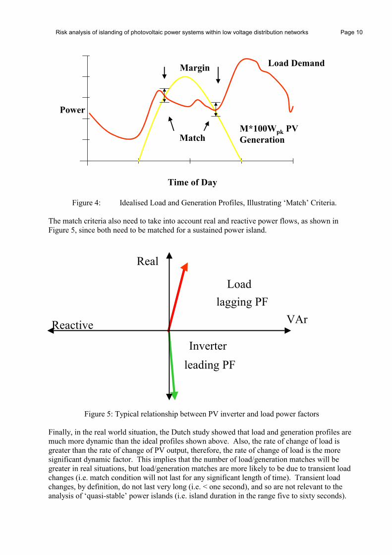
The match criteria also need to take into account real and reactive power flows, as shown in Figure 5, since both need to be matched for a sustained power island.
Figure 5: Typical relationship between PV inverter and load power factors
Finally, in the real world situation, the Dutch study showed that load and generation profiles are much more dynamic than the ideal profiles shown above. Also, the rate of change of load is greater than the rate of change of PV output, therefore, the rate of change of load is the more significant dynamic factor. This implies that the number of load/generation matches will be greater in real situations, but load/generation matches are more likely to be due to transient load changes (i.e. match condition will not last for any significant length of time). Transient load changes, by definition, do not last very long (i.e. < one second), and so are not relevant to the analysis of ‘quasi-stable’ power islands (i.e. island duration in the range five to sixty seconds).
M*100Wpk PVGeneration
Load Demand
Match
Power
Time of Day
Margin
Real
Reactive
Load
lagging PF
Inverter
leading PF
VAr

Risk analysis of islanding of photovoltaic power systems within low voltage distribution networks Page 11 The Dutch study also showed that the probability of load/generation match is a function of PV penetration which can be characterised by a curve of the form shown in Figure 6. This provides us with some useful benchmark values for the risk analysis as calculated below:
Figure 6: Probability of load/generation match for different PV penetration factors
Using round numbers, if the average uptake of PV within an LV fused zone is less than 400Wp per house (corresponding roughly to 3 times the minimum demand or 1/3 of the after-diversity maximum demand, ADMD), the potential for islanding tends to zero as shown in Figure 6. The worst-case scenario is reached when the PV rating reaches approximately six times the minimum (night-time) load or 2/3 of the ADMD. In this case, using typical match criteria, the probability of a load/generation match lasting for one second is in the region of:
10-5 per second. [4.4] The Dutch study also showed how the stability of a power island has an exponentially decaying characteristic, similar to that shown in Figure 7.
Figure 7: Probability of islanding versus island duration
0
0.2
0.4
0.6
0.8
1
0 0.5 1 1.5 2 2.5 3PV Array Size (kWp)
Freq
uenc
y
890Wp
400Wp
0 5 10 15 20 25Island Duration (Seconds)
Risk analysis of islanding of photovoltaic power systems within low voltage distribution networks Page 12 Based on the Dutch data, the probability of load/generation match typically reduces by a factor of ten for island durations > 5 seconds. This reduces the probability of load/generation match to:
10-6 per second [4.5] This highlights the appropriateness of the “5 second delay” used in some countries as a safety precaution following disconnection of the mains supply. This delay allows any unstable island to decay before any manual operation is carried out on the LV network. Based on the data from the Dutch Study, it can be concluded that: • The probability of load/generation match (islanding) conditions is extremely small for PV
penetrations less than a certain level (typically <400Wp/house in the Dutch example) and so islanding is not an issue at low penetration levels.
• The probability of an island remaining stable for >60 seconds becomes extremely small for realistic load/generation match criteria and so ‘stable’ power islands are unlikely to occur at all in practice.
• A reasonable estimate for the probability of load/generation match conditions lasting up to a second is of the order of 10-5/second.
• The recommended ‘5 second time-delay’ corresponds well with the exponential decay of unstable island probabilities and so this is an appropriate delay for practical network maintenance activities, assuming safe working practices are adopted (e.g. “live-line” working practices) and reduces the probability to <10-6/second.
This information forms the basis for the estimate of load/generation match conditions, which is one of the key components of the risk analysis. These values will be used in the risk calculation carried out in Section 7.

Risk analysis of islanding of photovoltaic power systems within low voltage distribution networks Page 13
5 INVERTER
5.1 Inverter Risk Analysis Fault Tree For an inverter to detect loss of mains supply, three conditions need to be satisfied. Firstly, the protection must be designed correctly and be operational. Secondly, the inverter must be installed correctly (i.e. with the protection enabled and the correct limits set). Thirdly, the inverter must be operating within its “detection zone”. Thus, failure to meet of any one of these criteria will lead to the inverter failing to detect loss of mains. This is shown in the inverter risk analysis fault tree in Figure 8.
Figure 8: Inverter Risk analysis Fault Tree
5.2 Protection Failure The success of the protection system will depend on its correct design and the reliability of its components, often expressed as the ‘availability’ of the protection system. For example, the islanding software could detect the presence of an island but fail to disconnect the inverter. Failure modes include either hardware failure or software failure. With hardware failure, it is important to distinguish between failure of the device (e.g. MTBF 10000 hours of operation) and failure in an unsafe way. The latter could arise from such things as failure of the control circuits that normally cause the inverter to shut down or a failure of the disconnect device itself. Software failure includes the software actually used to detect the island and the software communicating with the disconnect relay. Loss of mains supply is an infrequent event. The ‘low demand mode of operation’ means that ‘performance on demand’ is the appropriate assessment criterion. Functional loss of mains tests have been developed by many countries to provide a measure of this ‘performance on demand’. A combination of repeat tests and stringent test parameter values provides some indication as to the safety integrity level of the inverter. We have chosen a value of:
10-3 (boundary between SIL 2 and SIL 3) [5.1]
OR
NON-DETECTION ZONE (NDZ) (V, F, LOM)
PROTECTION FAILURE (Design/
Reliability)
INSTALLATION INCORRECT
(Limits set incorrectly)

Risk analysis of islanding of photovoltaic power systems within low voltage distribution networks Page 14 for the SIL level of the inverter protection, based on type testing of inverter loss of mains. This corresponds to 10 consecutive successful operations when asked to perform on demand (i.e. (1/2)10 ≈ 10-3).
Note: reliability and safety are not the same: it is possible that the safety of a system with relatively unreliable components, in a redundant structure, could be higher than the safety of a system with a simpler structure but with more reliable components (See BE EN 954-1). The probability of the islanding protection failing to operate could be reduced by:
• Selection of components: the use of accredited suppliers (i.e ISO9001 or similar)
• System structure – design for redundancy
• Self test function within the unit
• Periodic checking (difficult to implement)
5.3 Incorrect Installation The inverter, although designed and working correctly, could still fail to provide the required protection if it is installed incorrectly. This could arise from:
• incompetent installation • vandalism/tampering • illegal connection (e.g. ‘Guerrilla Solar’)
This could pose a hazard in one of two ways: i) Use of a non-approved inverter. This may contain ‘sufficient’ islanding protection but
there is no guarantee. ii) Software settings (protection, voltage/frequency) are incorrect. The risk can be reduced in three ways: i) Training of installers (see definition of Competence of persons in IEC 61508 –
awareness of critical failure modes) ii) Use of a self-testing inverter (see Sunny Boy technical description) i.e. inverter will
disconnect itself unless correctly installed iii) Protect voltage and frequency setpoints with passwords or other suitable means
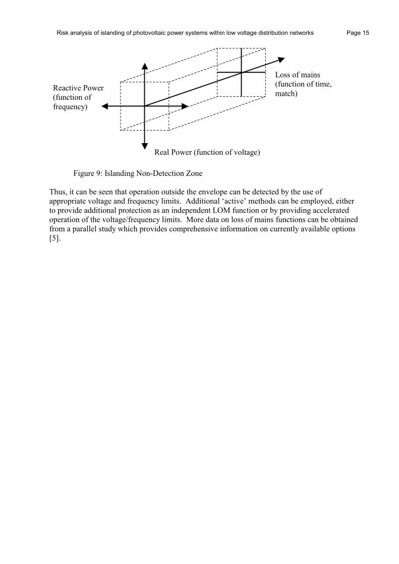
5.4 Islanding Non-Detection Zone (NDZ) The non-detection zone [5], as shown in Figure 9, can be used as a way to visualise the normal operating ‘envelope’ for the inverter. The NDZ boundaries reflect the match of both real and reactive power (function of voltage/phase/frequency) sustained for a long enough period to qualify as an ‘island’ (this is taken as 5 seconds in several countries).
Risk analysis of islanding of photovoltaic power systems within low voltage distribution networks Page 15
Figure 9: Islanding Non-Detection Zone
Thus, it can be seen that operation outside the envelope can be detected by the use of appropriate voltage and frequency limits. Additional ‘active’ methods can be employed, either to provide additional protection as an independent LOM function or by providing accelerated operation of the voltage/frequency limits. More data on loss of mains functions can be obtained from a parallel study which provides comprehensive information on currently available options [5].
Reactive Power (function of frequency)
Real Power (function of voltage)
Loss of mains (function of time, match)

Risk analysis of islanding of photovoltaic power systems within low voltage distribution networks Page 16
6 OPERATORS This section can be divided conveniently into ‘network operators’ and ‘domestic customers’ (i.e. operators of PV systems). A table of relative risks, derived from readily available publications, is given in the appendix to put the risk values we have chosen in perspective.
6.1 Network Operators The nature of the electricity industry means that strict working practices have been developed over a long period of time to ensure that the working environment is as safe as possible. It is necessary to establish some form of benchmark for the level of safety within the industry in order to put the risk analysis of PV islanding in context. Whilst it is a rather crude measure of safety, the number of deaths per year provides some form of benchmark which can be used in this study. Exact statistics are hard to establish, but it is generally agreed when performing risk assessments in the work environment from UK data that a ‘broadly acceptable’ level of risk at work is in the region of: 10-5 per year [6.1] Our benchmark of: 10-6 per year [6.2] for death by electric shock of a UK electricity operative has been derived from available statistics and confirmed approximately by our specific enquiries in UK electricity distribution companies. Live-line working practices are well established in many countries, including the UK. When following these procedures on LV networks, it is part of the procedure to take all reasonable steps to make the circuit dead and to check that the circuit is dead and earthed before performing any activity which could involve touching the conductor. During the maintenance operation, the conductors are then still treated as if they were live, just in case a mistake is made.
6.2 Customer Network operators have a duty of care to ensure appropriate safety for its customers, and so consideration needs to be given to the safety of customers who operate grid-connected PV systems. The risks associated with electric shock on conventional systems are commonly well understood by the general public, but we do not have any data readily available on electric shock in the home. All accidents in the home have an individual risk similar to that for road accidents, which is relatively high. A better benchmark for this study is perhaps the risk to the general public from all uses of gas. This is just over
2x10⁻⁶/year [6.3] which is the figure we have used.

Risk analysis of islanding of photovoltaic power systems within low voltage distribution networks Page 17 7 ISLANDING AND RISK Having analysed the sub-components of the risk analysis, it is now possible to assess the risk of islanding for network operators and customers. Based on the data presented in the previous sections, the risk of islanding to network operators and customers can be examined first using a scenario where there are no safety measures (i.e. no loss of mains protection, unsafe working practices by the operator, where islands with duration greater than one second are a cause for concern). The detailed mathematics behind the risk calculation is contained in Information Box 7.1, whilst the basic framework is illustrated in Figure 10.
INVERTER
Worst-case (no LOM) 1.0(Typical <1.0E-3)
INVERTER
Worst-case (no LOM) 1.0(Typical: 10-3)
AND
OPERATOR
Worst Case: 1.0(Typical: 1.0E-03)
OPERATOR
Worst Case: 1.0(Typical: 10-3)
RISK
8.3E-07/year (cable)8.3E-06/year (o/h)
RISK
8.3*10-7/year (cable)8.3*10-6/year (o/h)
AND
NETWORK
Load/Generation Match1.0E-5/secxNetwork Zone - loss of supply0.2/year (cable) 6.3E-09/sec2/year (o/h line)6.3E-08/sec
NETWORK
Load/Generation Match10-5/secxNetwork Zone - loss of supply0.2/year (cable) 6.3*10-9/sec2/year (o/h line)6.3*10-8/sec
ISLANDING(>2 seconds)
1.3E07 seconds/year8.3E-07/year (cable)or 8.3E-06/year (o/h)
ISLANDING(>1 second)
1.3*107 seconds/year8.3*10-7/year (cable)or 8.3*10-6/year (o/h)
Figure 10: Risk Calculation with “No Safety Measures” As described previously, based on equation 2.1, the risk of islanding is calculated as: Risk(islanding) = P(match) * P(LOM) * P(protection failure) Using the method described in Information Box 7.1 and the values given in Figure 10, we have:
Cable network, Risk(islanding) = (1.0*10-5) * (6.3*10-9) * (1.3*107) = 8.19*10-7 [7.1] Overhead line, Risk(islanding) = (1.0*10-5) * (6.3*10-8) * (1.3*107) = 8.19*10-6 [7.2]
From Section 6, the benchmark risk for network operators is 10-6 per year and for a customer is 2x10⁻⁶. In this case, we see that the additional risk posed by islanding is of the same order as the risk that already exits, which is not acceptable. Thus, some additional safety measures are necessary. If we first consider the network operator and his network maintenance staff, we have the revised

Risk analysis of islanding of photovoltaic power systems within low voltage distribution networks Page 18 scenario, as shown in Figure 11. In this case, we are using a value of 10-3 for the contribution from the inverter loss of mains protection, with safe working practices providing an additional improvement in safety of 10-3. In addition, working practices are assumed to be in place such that only islands of duration >5 seconds are of concern. This gives an additional reduction of risk by a factor of 10-1. Also, the exposure rate of maintenance staff is higher than the base case, since they are actually working on networks on a daily basis. This is reflected in the risk calculation.
INVERTER
(Worst-case (no LOM) 1.0)Typical <1.0E-3
INVERTER
(Worst-case (no LOM) 1.0)Typical: 10-3
ISLANDING(>5 seconds)
2.0E-06/year
ISLANDING(>5 seconds)
2.0*10-6/year
AND
OPERATOR
(Worst Case: 1.0)Typical: 1.0E-03
OPERATOR
(Worst Case: 1.0)Typical: 10-3
RISK
2.0E-09/year
RISK
2.0*10-9/year
AND
NETWORK
Load/Generation Match1.0E-5/secxNetwork Zone - loss of supply8 ops per day = 2000/year =2.8E-04/sec
NETWORK
Load/Generation Match10-5/secxNetwork Zone - loss of supply8 ops per day = 2000/year =2.8*10-4/sec
ISLANDING(>2 seconds)
7.2E06 seconds/year
2.0E-05/year
ISLANDING(>1 second)
7.2*106 seconds/year
2.0*10-5/year
X0.1
Figure 11: Risk Calculation for Network Maintenance Staff Thus, the revised calculation for the Risk (islanding) becomes:
= (1.0*10-5) * (2.8*10-4) * (10-3) * (10-3) * (7.2*106) * (10-1) = 2.0*10-9 [7.3] In this scenario, the additional risk is reduced to 2.0x10⁻⁹, which is approximately three orders of magnitude better than the risk that already exists. This is within the limits of acceptability, since the additional risk should be more than offset by improvements in safety as a result of greater awareness of the risk of electric shock in general, brought about by the introduction of grid-connected PV systems. Finally, if the scenario for domestic customers is considered, we assume a conservative value for safe working practices of only 10-1. The exposure rate reverts to the base case model, whilst the contribution of the LOM protection and the >5 second island duration is the same as in the network maintenance staff scenario. This scenario is illustrated in Figure 12.

Risk analysis of islanding of photovoltaic power systems within low voltage distribution networks Page 19
NETWORK
Load/Generation Match1.0E-5/secxNetwork Zone - loss of supply0.2/year (cable) 6.3E-09/sec2/year (o/h line)6.3E-08/sec
NETWORK
Load/Generation Match10-5/secxNetwork Zone - loss of supply0.2/year (cable) 6.3*10-9/sec2/year (o/h line)6.3*10-9/sec
INVERTER
(Worst-case (no LOM) 1.0)Typical <1.0E-3
INVERTER
(Worst-case (no LOM) 1.0)Typical: 10-3
ISLANDING(>5 seconds)
8.3E-11/year (cable)8.3E-10/year (o/h line)
ISLANDING(>5 seconds)
8.3*10-11/year (cable)8.3*10-10/year (o/h line)
AND
OPERATOR
(Worst Case: 1.0)Typical: 1.0E-01
OPERATOR
(Worst Case: 1.0)Typical: 10-1
RISK
8.3E-12/year (cable)8.3E-11/year (o/h)
RISK
8.3*10-12/year (cable)8.3*10-11/year (o/h)
AND
ISLANDING(>2 seconds)
1.3E07 seconds/year8.3E-10/year (cable)
8.3E-09/year (o/h line)
ISLANDING(>1 second)
1.3*107 seconds/year8.3*10-10/year (cable)
8.3*10-9/year (o/h line)
1X0.1
Figure 12: Risk Calculation for a Customer with PV system In this case, the calculation for Risk(islanding) in overhead line networks becomes:
= (1.0*10-5) * (6.3*10-8) * (10-3) * (10-1) * (1.3*107) * (10-1) = 8.3*10-11 [7.4] In this case, the additional risk is calculated at better than 10-10, which is four orders of magnitude better than the risk that already exists, which is well within the limits of acceptability. The additional risk that grid-connected PV systems may pose can be addressed by the use of suitable warning signs at the main locations where the additional danger may be present. Indeed, the use of warning labels at the consumer unit is recommended practice in many countries. A method of confirmation that the circuit is dead before manual work commences also forms part of recommended practices in many countries as well.
Risk analysis of islanding of photovoltaic power systems within low voltage distribution networks Page 20
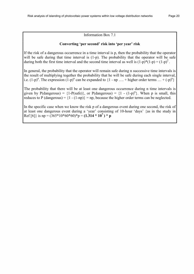
Information Box 7.1
Converting ‘per second’ risk into ‘per year’ risk If the risk of a dangerous occurrence in a time interval is p, then the probability that the operator will be safe during that time interval is (1-p). The probability that the operator will be safe during both the first time interval and the second time interval as well is (1-p)*(1-p) = (1-p)2 . In general, the probability that the operator will remain safe during n successive time intervals is the result of multiplying together the probability that he will be safe during each single interval, i.e. (1-p)n. The expression (1-p)n can be expanded to {1 - np …. + higher order terms … + (-p)n} The probability that there will be at least one dangerous occurrence during n time intervals is given by P(dangerous) = {1-P(safe)}, or P(dangerous) = {1 - (1-p)n}. When p is small, this reduces to P (dangerous) = {1 - (1-np)} = np, because the higher order terms can be neglected. In the specific case when we know the risk p of a dangerous event during one second, the risk of at least one dangerous event during a ‘year’ consisting of 10-hour ‘days’ {as in the study in Ref [6]} is np = (365*10*60*60)*p = (1.314 * 107 ) * p

Risk analysis of islanding of photovoltaic power systems within low voltage distribution networks Page 21
8 CONCLUSIONS AND RECOMMENDATIONS • The “benchmark” risk that already exists for network operators and customers is of the order
of 10-6 per year for an individual person • The risk of electric shock associated with islanding of PV systems under worst-case PV
penetration scenarios to both network operators and customers is typically <10-9 per year • Thus, the additional risk presented by islanding does not materially increase the risk that
already exists as long as the risk is managed properly • Loss of mains (LOM) protection functionality provides additional safety, up to a point:
• An inverter’s designed safety integrity level (SIL) affects the level of risk • The quality of the installation and any subsequent maintenance will also affect the risk
• There is a need to inform and educate both network operators and customers about the implications of the use of PV as an embedded micro-generator, as PV systems become more widespread.
It is recommended that: • Since LOM functionality is included in many PV inverters already, it is appropriate to
maintain this requirement, but emphasis should be put on simple, robust, verifiable and cost-effective solutions (e.g: software-based).
• The findings of this report should be:
i) incorporated into the training and education programmes of network operators and PV
system installers
ii) reviewed by appropriate interconnection standards working groups
iii) publicised in appropriate professional institutional journals and subjected to thorough public peer review

Risk analysis of islanding of photovoltaic power systems within low voltage distribution networks Page i
REFERENCES 1 IEA Task V: report IEA-PVPS V-1-04: ‘Information on electrical distribution systems in
related IEA countries (revised version)’, March 1998. 2 IEA Task V: report T5-01:1998: ‘Utility aspects of grid connected photovoltaic systems’,
December 1998. 3 IEA Task V: “Proceedings of the Task V Workshop on Islanding”, Zurich, September
1997. 4 UK Electricity Association, “Recommendations for the connection of inverter-connected
single-phase photovoltaic (PV) generators up to 5kVA to public distribution networks”, UK Engineering Recommendation G77, 2000.
5 Ward Bower and Michael Ropp: “Evaluation of Islanding detection methods for
photovoltaic utility-interactive power systems”, Task V Report, January 2002. 6 Bas Verhoeven: “Probability of Islanding in utility networks due to grid connected
photovoltaic power systems”, Task V Report, January 2002. 7 Risk Standard IEC 61508: “Functional safety of electrical/electronic/programmable
electronic safety-related systems”, 1998. 8 The Tolerability of Risks from Nuclear Power Stations. UK Health and Safety Executive
publication. HSE Books 1992. ISBN 0 11 88368 1 9 Reducing Risks, Protecting People - HSE’s decision-making process. UK Health and
Safety Executive publication. HSE Books 2001. ISBN 0 7176 2151 0. {Discussion Version (DV)was published in 1999}
10 Godfrey PS. Control of Risk: A Guide to the Systematic Management of Risk from
Construction. UK Construction Industry Research and Information Association (CIRIA) Special Report SP 125, 1996.
11 Hambly EC. Risk evaluation and Realism. In Proceedings of UK Institution of Civil
Engineers, Civil Engineering, Vol 102 Issue 2, May 1994. 12 UK Annual Abstract of Statistics, 1999 Edition, HMSO

Risk analysis of islanding of photovoltaic power systems within low voltage distribution networks Page ii
ACKNOWLEDGEMENTS The authors would like to acknowledge the IEA PVPS Programme for providing the international collaborative framework for this project and the other related complementary studies. Thanks are also due to the members of the IEA PVPS Task V Working Group, for providing invaluable peer review of this report, with special thanks to Bas Verhoeven (KEMA), without whose data on the Dutch islanding study this risk analysis report would not have been possible. In addition, thanks are also due to the DTI, through ETSU, for supporting this work. Finally, the authors would also like to express thanks for the assistance of several UK network operators who kindly supplied information related to network performance and operational practices for this study.

Risk analysis of islanding of photovoltaic power systems within low voltage distribution networks Page iii
APPENDIX A: TABLE OF RELATIVE RISK
1 UK population, 1993 1.14 * 10-2 1 [9, DV, Table 1]
2 Injury only, from burn or scald in the home 1.64 * 10-3 7 [9, App 4, Table 4]
3 Women, UK, aged 35-44 1.10 * 10-3 10 [9, DV, Table 1]
4Upper limit of tolerability for workers 1.00 * 10-3 11 [9, Box in Para 128]
5 All accidents, UK 2.46 * 10-4 46 [9, App 4, Table 2]
6 Boys, UK, aged 5-14 2.00 * 10-4 57 [9, DV, Table 1]
7
Upper limit of tolerability for members of the public who have a risk 'imposed' on them 'in the wider interest of society'
1.00 * 10-4 114[9, Box in Para 128]
& [ 9, Para 132]
8 All accidents at homeless than
8.76 * 10-5 130 [D] from [11, Table 1]
9 All road accidents, UK 5.95 * 10-5 191 [9, App 4, Table 2]
10 Construction Worker 4.66 * 10-5 244 [9, Box in Para 128]
11All deaths in electricity, gas and water supply (2 p.a. for over 200,000 employees)
less than 1.00 * 10-5 1,136 [12, Tables 9.8 and 7.5]
12 Service Sector Worker 3.00 * 10-6 3,784 [9, App 4, Table 3]
13General Public from all uses of gas(fire, explosion, poisoning) 1.96 * 10-6 5,795 [9, Box in Para 128]
14Electric shock to electricity distribution operative 1.00 * 10-6 11,364
Derived from [12] using: 1/20 of construction deaths
are by electric shock [10], but only 50% of workers are at
risk [D]
15Lightning (England and Wales) 5.35 * 10-8 212,500 [9, App 4, Table 2]
Rank
Relative Risk (in orders of magnitude)
Values
Individual risk,
per year
Relative likelihood,
1 in
Risk Description (Death unless otherwise stated)
Source of Information[D] = Derived by authorsNumbers refer to References Section
Risk analysis of islanding of photovoltaic power systems within low voltage distribution networks Page iv
LIST OF IEA PVPS TASK V PARTICIPANTS: AUSTRALIA Mr. Phil GATES Energy Australia L14 570 George St. Sydney, New South Wales 2000 +612-9269-7366 +612-9269 7372 email: [email protected]
AUSTRIA Mr. Christoph PANHUBER Fronius International GmbH Gunter-Fronius-Strasse 1 Wels-Thalheim A-4600 +43-7242-241-199 +43-7242-241-224 email - [email protected]
AUSTRIA Dr. Gerd SCHAUER Verbundplan Parkring 12 Wien A-1010 +43-1-53113-52439 +43-1-53113-52469 email: [email protected]
DENMARK Mr. Arne Faaborg POVLSEN Elsam A/S M. SC. Elec. Eng. Overgade 45 DK-7000 Fredericia +45-7622-2408 +45-7522-2450 email - [email protected]
GERMANY Mr. Hermann LAUKAMP Fraunhofer Institut fuer Solare Energiesysteme Heidenhofster. 2 Freiburg, D-79770 +49-761-4588-5275 +49-761-4588-9000 email – [email protected]
ITALY Mr. Francesco GROPPI CESI S.p.A. Via Rubattino, 54, Milano 20134 +39-(0)2-2125 5686 +39-(0)2-2125 5626 email: [email protected]
JAPAN Mr. Tadashi KANBAYASHI (TaskV Operating Agent) NEDO, New Energy Promotion Dept. Sunshine 60, 29F; 1-1,3-Chome Higashi-Ikebukuro, Toshima-ku Tokyo, 170-6028, +81-3-3987-9367 +81-3-3590-5803 email – [email protected]
JAPAN Mr. Tadao ISHIKAWA (Task V Chairman) CRIEPI Customer Systems Department 2-11-1 Iwado-kita, Komae-shi Tokyo 201-8511 +81-3-3480-2111 +81-3-3480-3866 email: [email protected]
Risk analysis of islanding of photovoltaic power systems within low voltage distribution networks Page v
JAPAN Mr. Hiromu KOBAYASHI CRIEPI Customer Systems Dept., 2-11-1 Iwado-kita, Komae-shi Tokyo, 201 +81-3-3480-2111 +81-3-3430-4014 email - [email protected]
JAPAN Mr. Hiroaki MIZUNAGA NEDO, New Energy Promotion Dept. Sunshine 60, 27F; 1-1,3-Chome Higashi-Ikebukuro, Toshima-ku Tokyo, 170-6028, +81-3-3987-9319 +81-3-3590-5803 email – [email protected]
JAPAN NEDO, Mr. Masaki HOSODA New Energy Promotion Dept. Sunshine 60, 27F; 1-1,3-Chome Higashi-Ikebukuro, Toshima-ku Tokyo, 170-6028, +81-3-3987-9319 +81-3-3590-5803 email – [email protected]
MEXICO Mr. Oscar ARTEAGA Institudo de Investigationes Electricas (IIE) Non Conventional Energies Unit Av. Reforma No. 113, Temixco Morelos, 62490 +13 18 38 11 Ext. 7244, +13 18 24 36, email: [email protected]
NETHERLANDS Mr. Bas VERHOEVEN KEMA Utrechtseweg 310 Arnhem 6812 AR +31-263-56-3581 +31-263-51-3843 email: [email protected]
PORTUGAL Mr. Petro Sassetti PAES EDP-Electriciadade de Portugal, S.A. Gabinete de Investigacao e Desenvolvimento Av. Infante Santo, 17-6 Lisbon, 1350 +351-1-395-5900 +351-1-390-2531 email: [email protected]
SWITZERLAND Mr. Sergio TAIANA ewz Tramstrasse 35 Postfach, Zurich 8050 +31-1-319-44-55 +31-1-319-41-97 email: [email protected]
SWITZERLAND Mr. Daniel RUOSS Enecolo Lindhofstrasse 52 Mönchaltorf CH-8617 +41-(0)1-994-9001 +41-(0)1-994-9005 email: [email protected]

Risk analysis of islanding of photovoltaic power systems within low voltage distribution networks Page vi
UNITED KINGDOM Dr. Alan COLLINSON EA Technology Capenhurst Chester CH1 6ES +44-151-347-2396 +44-151-347-2135 email: [email protected]
UNITED KINGDOM Mr. Harry EDWARDS, AEA Technology Harwell, Didcot, Oxfordshire OX11 0RA +44 1235-436457 +44-1235-432331 e-mail - [email protected]
USA Mr. Ward BOWER Sandia National Laboratories Photovoltaic System Applications, MS0753 Albuquerque, NM 87185-0753 +1-505-844-5206 +1-505-844-6541 e-mail: [email protected]
UNITED KINGDOM Mr. James THORNYCROFT Halcrow, Ltd. Burderop Park, Swindon Wiltshire SN4 0QD +44-793-814756 +44-793-815020 e-mail: [email protected]
Related Documents