Your new table saw has been engineered and manufactured to our high standards for dependability, ease of operation, and operator safety. When properly cared for, it will give you years of rugged, trouble-free performance. WARNING: To reduce the risk of injury, the user must read and understand the operator’s manual before using this product. Thank you for buying a RIDGID product. OPERATOR’S MANUAL 10 in. CAST IRON TABLE SAW TS3650 SAVE THIS MANUAL FOR FUTURE REFERENCE

Welcome message from author
This document is posted to help you gain knowledge. Please leave a comment to let me know what you think about it! Share it to your friends and learn new things together.
Transcript

Your new table saw has been engineered and manufactured to our high standards for dependability, ease of operation, and operator safety. When properly cared for, it will give you years of rugged, trouble-free performance.
WARNING:To reduce the risk of injury, the user must read and understand the operator’s manual before using this product.
Thank you for buying a RIDGID product.
OPERATOR’S MANUAL10 in. CAST IRON TABLE SAWTS3650
SAVE THIS MANUAL FOR FUTURE REFERENCE
Æ
®
®

2 3
n Introduction ...................................................................................................................................................................... 2
n General Safety Rules .....................................................................................................................................................3-4
n Specific Safety Rules.....................................................................................................................................................4-5
n Symbols.........................................................................................................................................................................6-7
n Electrical ......................................................................................................................................................................8-10
n Glossary of Terms........................................................................................................................................................... 11
n Features.....................................................................................................................................................................12-13
n Tools Needed ................................................................................................................................................................. 14
n Loose Parts................................................................................................................................................................15-16
n Assembly ...................................................................................................................................................................17-27
n Operation...................................................................................................................................................................28-39
n Adjustments...............................................................................................................................................................40-46
n Maintenance ................................................................................................................................................................... 47
n Accessories .................................................................................................................................................................... 47
n Troubleshooting .........................................................................................................................................................48-49
n Warranty ......................................................................................................................................................................... 51
n Parts Ordering/Service ................................................................................................................................................... 52
TABLE OF CONTENTS
This tool has many features for making the use of this product more pleasant and enjoyable. Safety, performance, and dependability have been given top priority in the design of this product making it easy to maintain and operate.
INTRODUCTION
2 3
WARNING:Read and understand all instructions. Failure to follow all instructions listed below, may result in electric shock, fire and/or serious personal injury.
READ ALL INSTRUCTIONSn KNOW YOUR POWER TOOL. Read the operator's
manual carefully. Learn the tool’s applications and limitations as well as the specific potential hazards related to this tool.
n GUARD AGAINST ELECTRICAL SHOCK BY PREVENTING BODY CONTACT WITH GROUNDED SURFACES. For example: pipes, radiators, ranges, refrigerator enclosures.
n KEEP GUARDS IN PLACE and in working order. Never operate the tool with any guard or cover removed. Make sure all guards are operating properly before each use.
n REMOVE ADJUSTING KEYS AND WRENCHES. Form habit of checking to see that keys and adjusting wrenches are removed from tool before turning it on.
n KEEP WORK AREA CLEAN. Cluttered areas and benches invite accidents. DO NOT leave tools or pieces of wood on the saw while it is in operation.
n AVOID DANGEROUS ENVIRONMENT. Don't use power tools in damp or wet locations or expose to rain. Keep work area well lit.
n KEEP CHILDREN AND VISITORS AWAY. All visitors should wear safety glasses and be kept a safe distance from work area. Do not let visitors contact tool or extension cord while operating.
n MAKE WORKSHOP CHILDPROOF with padlocks or master switches, or by removing starter keys.
n DON'T FORCE TOOL. It will do the job better and safer at the feed rate for which it was designed.
n USE RIGHT TOOL. Don't force tool or attachment to do a job it was not designed for. Don't use it for a purpose not intended.
n MAKE SURE YOUR EXTENSION CORD IS IN GOOD CONDITION. When using an extension cord, be sure to use one heavy enough to carry the current your product will draw. An undersized cord will cause a drop in line voltage resulting in loss of power and overheating. A wire gauge size (A.W.G.) of at least 14 is recommended for an extension cord 25 feet or less in length. If in doubt, use the next heavier gauge. The smaller the gauge number, the heavier the cord.
GENERAL SAFETY RULES
n DRESS PROPERLY. Do not wear loose clothing, gloves, neckties, or jewelry. They can get caught and draw you into moving parts. Rubber gloves and nonskid footwear are recommended when working outdoors. Also wear protective hair covering to contain long hair.
n ALWAYS WEAR SAFETY GLASSES WITH SIDE SHIELDS. Everyday eyeglasses have only impact-resistant lenses; they are NOT safety glasses.
n SECURE WORK. Use clamps or a vise to hold work when practical. It's safer than using your hand and frees both hands to operate tool.
n DON'T OVERREACH. Keep proper footing and balance at all times.
n MAINTAIN TOOLS WITH CARE. Keep tools sharp and clean for better and safer performance. Follow instructions for lubricating and changing accessories.
n DISCONNECT TOOLS. When not in use, before servicing, or when changing attachments, blades, bits, cutters, etc., all tools should be disconnected.
n AVOID ACCIDENTAL STARTING. Be sure switch is off when plugging in.
n USE RECOMMENDED ACCESSORIES. The use of improper accessories may cause risk of injury.
n NEVER STAND ON TOOL. Serious injury could occur if the tool is tipped or if the cutting tool is unintentionally contacted.
n CHECK DAMAGED PARTS. Before further use of the tool, a guard or other part that is damaged should be carefully checked to determine that it will operate properly and perform its intended function. Check for alignment of moving parts, binding of moving parts, breakage of parts, mounting and any other conditions that may affect its operation. A guard or other part that is damaged must be properly repaired or replaced by an authorized service center to avoid risk of personal injury.
n USE THE RIGHT DIRECTION OF FEED. Feed work into a blade or cutter against the direction of rotation of blade or cutter only.
n NEVER LEAVE TOOL RUNNING UNATTENDED. TURN POWER OFF. Don't leave tool until it comes to a complete stop.
n PROTECT YOUR LUNGS. Wear a face or dust mask if the cutting operation is dusty.
n PROTECT YOUR HEARING. Wear hearing protection during extended periods of operation.
n DON'T ABUSE CORD. Never yank cord to disconnect from receptacle. Keep cord from heat, oil, and sharp edges.
4 5
n USE OUTDOOR EXTENSION CORDS. When tool is used outdoors, use only extension cords with approved ground connection that are intended for use outdoors and so marked.
n KEEP BLADES CLEAN AND SHARP. Sharp blades minimize stalling and kickback.
n BLADES COAST AFTER TURN OFF.
n NEVER USE IN AN EXPLOSIVE ATMOSPHERE. Normal sparking of the motor could ignite fumes.
n INSPECT TOOL CORDS PERIODICALLY. If damaged, have repaired by a qualified service technician at an authorized service facility. The conductor with insulation having an outer surface that is green with or without yellow stripes is the equipment-grounding conductor. If repair or replacement of the electric cord or plug is necessary, do not connect the equipment-grounding conductor to a live terminal. Repair or replace a damaged or worn cord immediately. Stay constantly aware of cord location and keep it well away from the rotating blade.
n INSPECT EXTENSION CORDS PERIODICALLY and replace if damaged.
n KEEP TOOL DRY, CLEAN, AND FREE FROM OIL AND GREASE. Always use a clean cloth when cleaning. Never use brake fluids, gasoline, petroleum-based products, or any solvents to clean tool.
n STAY ALERT AND EXERCISE CONTROL. Watch what you are doing and use common sense. Do not operate tool when you are tired. Do not rush.
n DO NOT USE TOOL IF SWITCH DOES NOT TURN IT ON AND OFF. Have defective switches replaced by an authorized service center.
n USE ONLY CORRECT BLADES. Do not use blades with incorrect size holes. Never use blade washers or bolts that are defective or incorrect. The maximum blade capacity of your saw is 10 in. (254 mm).
n BEFORE MAKING A CUT, BE SURE ALL ADJUSTMENTS ARE SECURE.
n AVOID CUTTING NAILS. Inspect for and remove all nails from lumber before cutting.
n NEVER TOUCH BLADE or other moving parts during use.
n NEVER START A TOOL WHEN ANY ROTATING COMPONENT IS IN CONTACT WITH THE WORK-PIECE.
n DO NOT OPERATE THIS TOOL WHILE UNDER THE INFLUENCE OF DRUGS, ALCOHOL, OR ANY MEDICATION.
n GROUND ALL TOOLS. If tool is equipped with three-prong plug, it should be plugged into a three-hole electrical receptacle.
n WHEN SERVICING use only identical replacement parts. Use of any other parts may create a hazard or cause product damage.
n CHECK WITH A QUALIFIED ELECTRICIAN or service personnel if the grounding instructions are not completely understood or if in doubt as to whether the tool is properly grounded.
n DO NOT MODIFY the plug provided. If it will not fit the outlet, have the proper outlet installed by a qualified electrician.
n USE ONLY RECOMMENDED ACCESSORIES listed in this manual or addendums. Use of accessories that are not listed may cause the risk of personal injury. Instructions for safe use of accessories are included with the accessory.
n DOUBLE CHECK ALL SETUPS. Make sure blade is tight and not making contact with saw or workpiece before connecting to power supply.
n MAKE SURE THE WORK AREA HAS AMPLE LIGHT-ING to see the work and that no obstructions willinterfere with safe operation BEFORE performing any work using the table saw.
GENERAL SAFETY RULES
SPECIFIC SAFETY RULES
n ALWAYS KEEP THE BLADE GUARD AND SPREADER (SPLITTER) IN PLACE and in working order.
n KEEP HANDS AWAY FROM CUTTING AREA. Keep hands away from blades. Do not reach underneath work or around or over the blade while blade is rotating. Do not attempt to remove cut material when blade is moving.
n GUARD AGAINST KICKBACK. Kickback occurs when the blade stalls rapidly and workpiece is driven back towards the operator. It can pull your hand into the blade resulting in serious personal injury. Stay out of blade path and turn switch off immediately if blade binds or stalls.
n USE RIP FENCE. Always use a fence or straight edge guide when ripping.
4 5
WARNING: Some dust created by power sanding, sawing, grinding, drilling, and other construction activities contains chemi-
cals known to cause cancer, birth defects or other reproductive harm. Some examples of these chemicals are:
• lead from lead-based paints, • crystalline silica from bricks and cement and other masonry products, and • arsenic and chromium from chemically-treated lumber. Your risk from these exposures varies, depending on how often you do this type of work. To reduce your ex-
posure to these chemicals: work in a well ventilated area, and work with approved safety equipment, such as those dust masks that are specially designed to filter out microscopic particles.
SPECIFIC SAFETY RULES
n SUPPORT LARGE PANELS. To minimize risk of blade pinching and kickback, always support large panels.
n REMOVE ALL FENCES AND AUXILIARY TABLES before transporting saw. Failure to do so can result in an accident causing possible serious personal injury.
n ALWAYS USE BLADE GUARD, SPREADER, AND ANTI-KICKBACK PAWLS on all "through-sawing" operations. Through-sawing operations are those in which the blade cuts completely through the workpiece as in ripping or crosscutting. Keep the blade guard down, the anti-kickback pawls down, and the spreader in place over the blade.
n ALWAYS SECURE WORK firmly against rip fence or miter fence.
n ALWAYS USE A PUSH STICK FOR RIPPING NARROW STOCK. A push stick is a device used to push a workpiece through the blade instead of using your hands. Size and shape can vary but the push stick must always be narrower than the workpiece to prevent the push stick from contacting the saw blade. When ripping narrow stock, always use a push stick, so your hand does not come close to the saw blade. Use a featherboard and push blocks for non-through cuts.
n NEVER perform any operation "freehand" which means using only your hands to support or guide the workpiece. Always use either the rip fence or miter fence to position and guide the work.
n NEVER stand or have any part of your body in line with the path of the saw blade.
n NEVER reach behind, over, or within three inches of the blade or cutter with either hand for any reason.
n MOVE THE RIP FENCE out of the way when cross-cutting.
n NEVER use r ip fence as cutoff gauge when crosscutting.
n NEVER attempt to free a stalled saw blade without first turning the saw OFF and disconnecting the saw from the power source.
n AVOID KICKBACKS (work thrown back toward you) by:
A. Keeping blade sharp.
B. Keeping rip fence parallel to the saw blade.
C. Keeping spreader, anti-kickback pawls, and blade guard in place and operating.
D. Not releasing the work before it is pushed all the way past the saw blade using a push stick.
E. Not ripping work that is twisted or warped or does not have a straight edge to guide along the fence.
n PROVIDE ADEQUATE SUPPORT to the rear and sides of the saw table for wide or long workpieces. Use a sturdy "outrigger" support if a table extension more than24 inches long is attached to the saw.
n AVOID AWKWARD OPERATIONS AND HAND POSITIONS where a sudden slip could cause your hand to move into the cutting tool.
n ALWAYS TURN OFF SAW before disconnecting it, to avoid accidental starting when reconnecting to power supply.
n SAVE THESE INSTRUCTIONS. Refer to them frequently and use to instruct other users. If you loan someone this tool, loan them these instructions also.

6 7
SYMBOLS
Some of the following symbols may be used on this tool. Please study them and learn their meaning. Proper interpreta-tion of these symbols will allow you to operate the tool better and safer.
Read The Operator’s Manual
Safety Alert
No Hands Symbol
No Hands Symbol
No Hands Symbol
No Hands Symbol
SYMBOL NAME DESIGNATION/EXPLANATION
Voltage
Current
Frequency (cycles per second)
Power
Time
Type of current
Type or a characteristic of current
Rotational speed, at no load
Double-insulated construction
Revolutions, strokes, surface speed, orbits etc., per minute
Do not expose to rain or use in damp locations.
To reduce the risk of injury, user must read and understand operator’s manual before using this product.
Eye ProtectionAlways wear safety goggles or safety glasses with side shields and a full face shield when operating this product.
Precautions that involve your safety.
Failure to keep your hands away from the blade will result in serious personal injury.
Failure to keep your hands away from the blade will result in serious personal injury.
Failure to keep your hands away from the blade will result in serious personal injury.
Failure to keep your hands away from the blade will result in serious personal injury.
Wet Conditions Alert
.../min Per Minute
Class II Construction
no No Load Speed
Direct Current
Alternating Current
min Minutes
W Watt
Hz Hertz
A Amperes
V Volts
Hot Surface To reduce the risk of injury or damage, avoid contact with any hot surface.
6 7
SYMBOLS
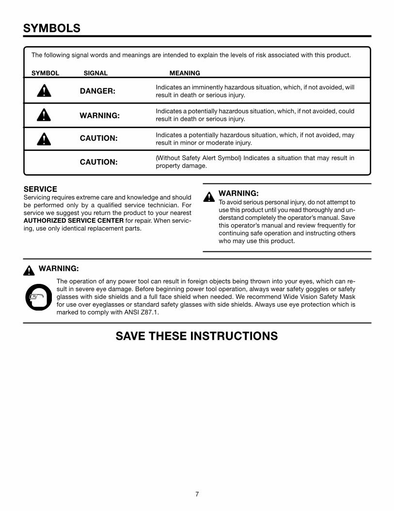
Indicates an imminently hazardous situation, which, if not avoided, will result in death or serious injury.
Indicates a potentially hazardous situation, which, if not avoided, could result in death or serious injury.
Indicates a potentially hazardous situation, which, if not avoided, may result in minor or moderate injury.
(Without Safety Alert Symbol) Indicates a situation that may result in property damage.
SYMBOL SIGNAL MEANING
SERVICEServicing requires extreme care and knowledge and should be performed only by a qualified service technician. For service we suggest you return the product to your nearest AUTHORIZED SERVICE CENTER for repair. When servic-ing, use only identical replacement parts.
WARNING:To avoid serious personal injury, do not attempt to use this product until you read thoroughly and un-derstand completely the operator’s manual. Save this operator’s manual and review frequently for continuing safe operation and instructing others who may use this product.
The operation of any power tool can result in foreign objects being thrown into your eyes, which can re-sult in severe eye damage. Before beginning power tool operation, always wear safety goggles or safety glasses with side shields and a full face shield when needed. We recommend Wide Vision Safety Mask for use over eyeglasses or standard safety glasses with side shields. Always use eye protection which is marked to comply with ANSI Z87.1.
WARNING:
SAVE THESE INSTRUCTIONS
DANGER:
CAUTION:
CAUTION:
WARNING:
The following signal words and meanings are intended to explain the levels of risk associated with this product.
8 9
ELECTRICAL
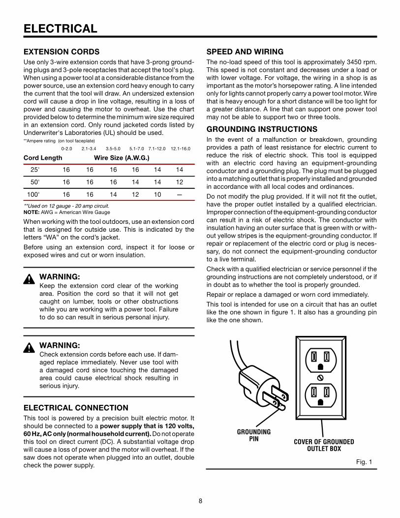
EXTENSION CORDSUse only 3-wire extension cords that have 3-prong ground-ing plugs and 3-pole receptacles that accept the tool's plug. When using a power tool at a considerable distance from the power source, use an extension cord heavy enough to carry the current that the tool will draw. An undersized extension cord will cause a drop in line voltage, resulting in a loss of power and causing the motor to overheat. Use the chart provided below to determine the minimum wire size required in an extension cord. Only round jacketed cords listed by Underwriter's Laboratories (UL) should be used.**Ampere rating (on tool faceplate)
0-2.0 2.1-3.4 3.5-5.0 5.1-7.0 7.1-12.0 12.1-16.0
Cord Length Wire Size (A.W.G.)
25' 16 16 16 16 14 14
50' 16 16 16 14 14 12
100' 16 16 14 12 10 —
**Used on 12 gauge - 20 amp circuit.NOTE: AWG = American Wire Gauge
When working with the tool outdoors, use an extension cord that is designed for outside use. This is indicated by the letters “WA” on the cord’s jacket.
Before using an extension cord, inspect it for loose or exposed wires and cut or worn insulation.
WARNING:Keep the extension cord clear of the working area. Position the cord so that it will not get caught on lumber, tools or other obstructions while you are working with a power tool. Failure to do so can result in serious personal injury.
WARNING:Check extension cords before each use. If dam-aged replace immediately. Never use tool with a damaged cord since touching the damaged area could cause electrical shock resulting in serious injury.
ELECTRICAL CONNECTIONThis tool is powered by a precision built electric motor. It should be connected to a power supply that is 120 volts, 60 Hz, AC only (normal household current). Do not operate this tool on direct current (DC). A substantial voltage drop will cause a loss of power and the motor will overheat. If the saw does not operate when plugged into an outlet, double check the power supply.
SPEED AND WIRINGThe no-load speed of this tool is approximately 3450 rpm. This speed is not constant and decreases under a load or with lower voltage. For voltage, the wiring in a shop is as important as the motor’s horsepower rating. A line intended only for lights cannot properly carry a power tool motor. Wire that is heavy enough for a short distance will be too light for a greater distance. A line that can support one power tool may not be able to support two or three tools.
GROUNDING INSTRUCTIONSIn the event of a malfunction or breakdown, grounding provides a path of least resistance for electric current to reduce the risk of electric shock. This tool is equipped with an electric cord having an equipment-grounding conductor and a grounding plug. The plug must be plugged into a matching outlet that is properly installed and grounded in accordance with all local codes and ordinances.
Do not modify the plug provided. If it will not fit the outlet, have the proper outlet installed by a qualified electrician. Improper connection of the equipment-grounding conductor can result in a risk of electric shock. The conductor with insulation having an outer surface that is green with or with-out yellow stripes is the equipment-grounding conductor. If repair or replacement of the electric cord or plug is neces-sary, do not connect the equipment-grounding conductor to a live terminal.
Check with a qualified electrician or service personnel if the grounding instructions are not completely understood, or if in doubt as to whether the tool is properly grounded.
Repair or replace a damaged or worn cord immediately.
This tool is intended for use on a circuit that has an outlet like the one shown in figure 1. It also has a grounding pin like the one shown.
Fig. 1
GROUNDING PIN COVER OF GROUNDED
OUTLET BOX
8 9
ELECTRICAL
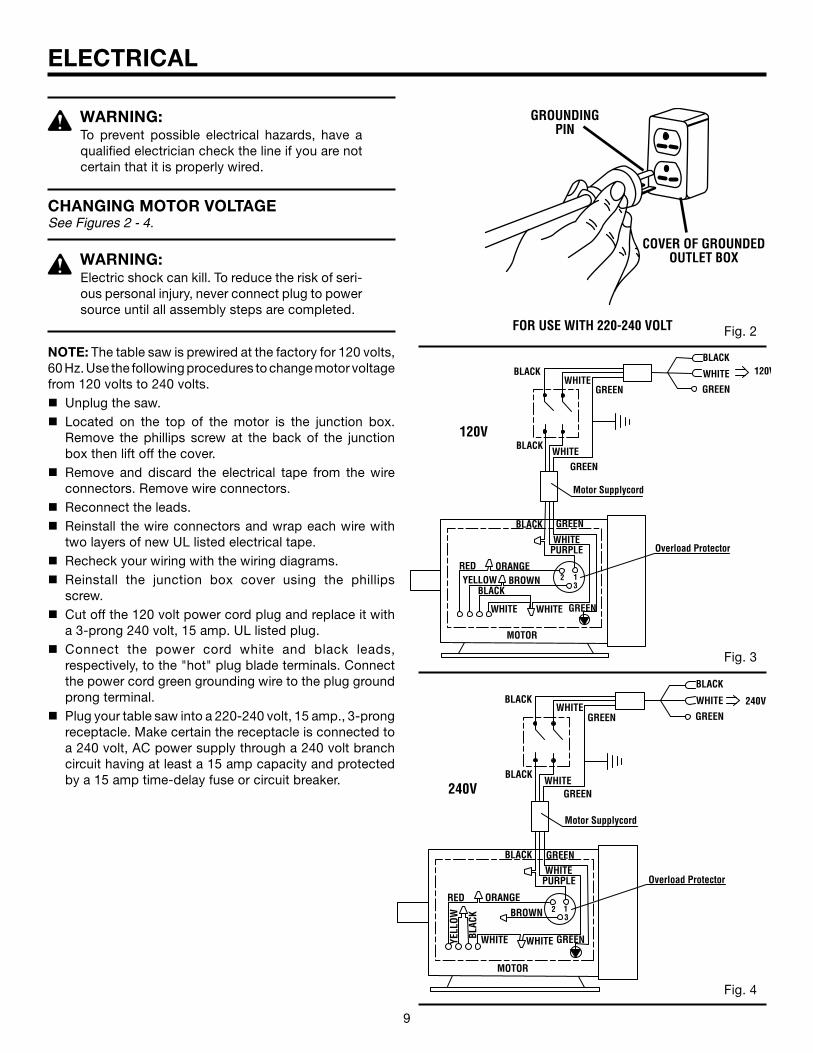
WARNING:To prevent possible electrical hazards, have a qualified electrician check the line if you are not certain that it is properly wired.
CHANGING MOTOR VOLTAGESee Figures 2 - 4.
WARNING:Electric shock can kill. To reduce the risk of seri-ous personal injury, never connect plug to power source until all assembly steps are completed.
NOTE: The table saw is prewired at the factory for 120 volts, 60 Hz. Use the following procedures to change motor voltage from 120 volts to 240 volts.n Unplug the saw.n Located on the top of the motor is the junction box.
Remove the phillips screw at the back of the junction box then lift off the cover.
n Remove and discard the electrical tape from the wire connectors. Remove wire connectors.
n Reconnect the leads.n Reinstall the wire connectors and wrap each wire with
two layers of new UL listed electrical tape.n Recheck your wiring with the wiring diagrams. n Reinstall the junction box cover using the phillips
screw.n Cut off the 120 volt power cord plug and replace it with
a 3-prong 240 volt, 15 amp. UL listed plug. n Connect the power cord white and black leads,
respectively, to the "hot" plug blade terminals. Connect the power cord green grounding wire to the plug ground prong terminal.
n Plug your table saw into a 220-240 volt, 15 amp., 3-prong receptacle. Make certain the receptacle is connected to a 240 volt, AC power supply through a 240 volt branch circuit having at least a 15 amp capacity and protected by a 15 amp time-delay fuse or circuit breaker.
Fig. 4
Fig. 2
Fig. 3
FOR USE WITH 220-240 VOLT
GROUNDING PIN
COVER OF GROUNDED OUTLET BOX
10 11
ELECTRICAL
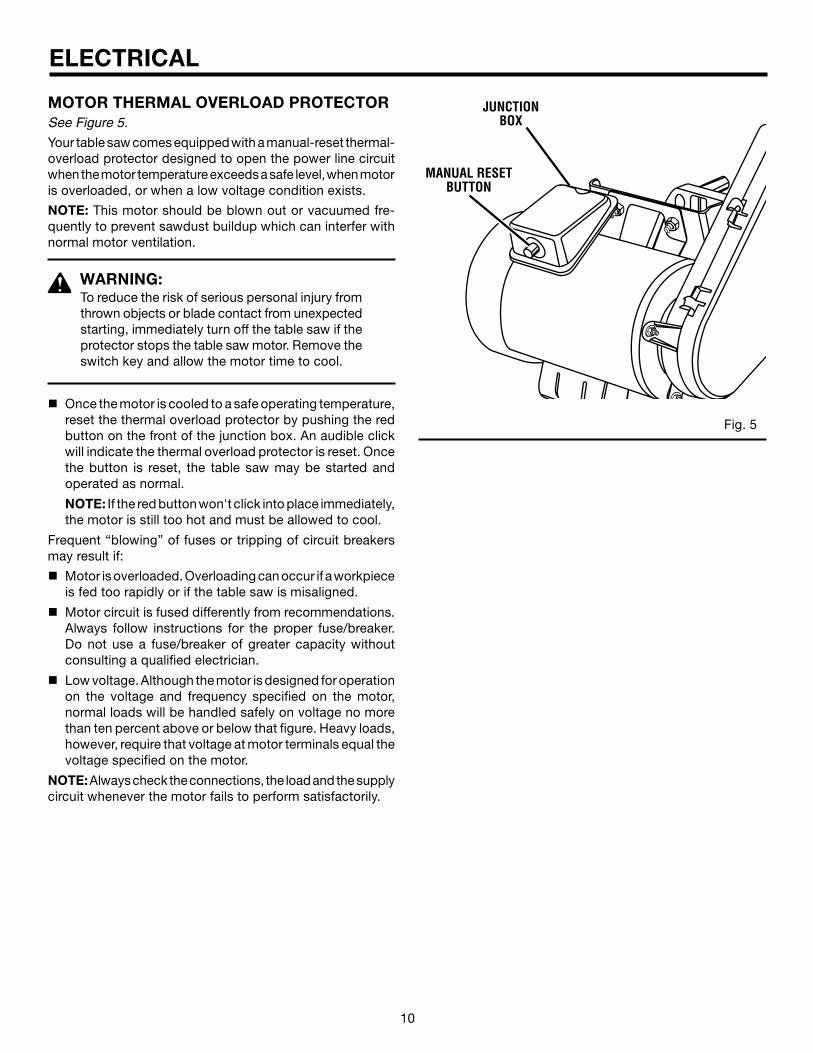
MOTOR THERMAL OVERLOAD PROTECTORSee Figure 5.
Your table saw comes equipped with a manual-reset thermal-overload protector designed to open the power line circuit when the motor temperature exceeds a safe level, when motor is overloaded, or when a low voltage condition exists.
NOTE: This motor should be blown out or vacuumed fre-quently to prevent sawdust buildup which can interfer with normal motor ventilation.
WARNING:To reduce the risk of serious personal injury from thrown objects or blade contact from unexpected starting, immediately turn off the table saw if the protector stops the table saw motor. Remove the switch key and allow the motor time to cool.
n Once the motor is cooled to a safe operating temperature, reset the thermal overload protector by pushing the red button on the front of the junction box. An audible click will indicate the thermal overload protector is reset. Once the button is reset, the table saw may be started and operated as normal.
NOTE: If the red button won't click into place immediately, the motor is still too hot and must be allowed to cool.
Frequent “blowing” of fuses or tripping of circuit breakers may result if:
n Motor is overloaded. Overloading can occur if a workpiece is fed too rapidly or if the table saw is misaligned.
n Motor circuit is fused differently from recommendations. Always follow instructions for the proper fuse/breaker. Do not use a fuse/breaker of greater capacity without consulting a qualified electrician.
n Low voltage. Although the motor is designed for operation on the voltage and frequency specified on the motor, normal loads will be handled safely on voltage no more than ten percent above or below that figure. Heavy loads, however, require that voltage at motor terminals equal the voltage specified on the motor.
NOTE: Always check the connections, the load and the supply circuit whenever the motor fails to perform satisfactorily.
Fig. 5
MANUAL RESET BUTTON
JUNCTION BOX

10 11
GLOSSARY OF TERMS
Non-Through CutsAny cutting operation where the blade does not extend completely through the thickness of the workpiece.
Push Blocks and Push SticksDevices used to feed the workpiece through the saw blade during cutting operations. A push stick (not a push block) should be used for narrow ripping operations. These aids help keep the operator's hands well away from the blade.
Pilot Hole (drill presses)A small hole drilled in a workpiece that serves as a guide for drilling large holes accurately.
ResawA cutting operation to reduce the thickness of the work-piece to make thinner pieces.
ResinA sticky, sap-based substance that has hardened.
Revolutions Per Minute (RPM)The number of turns completed by a spinning object in one minute.
Ripping or Rip CutA cutting operation along the length of the workpiece.
Riving Knife (table saws)Also known as a spreader or splitter. A metal piece, slightly thinner than the saw blade, which helps keep the kerf open and also helps to prevent kickback.
Saw Blade PathThe area over, under, behind, or in front of the blade. As it applies to the workpiece, that area which will be or has been cut by the blade.
SetThe distance that the tip of the saw blade tooth is bent (or set) outward from the face of the blade.
Snipe (planers)Depression made at either end of a workpiece by cutter blades when the workpiece is not properly supported.
Throw-BackThe throwing back of a workpiece usually caused by the workpiece being dropped into the blade or being placed inadvertently in contact with the blade.
Through SawingAny cutting operation where the blade extends completely through the thickness of the workpiece.
Workpiece or MaterialThe item on which the operation is being done.
WorktableSurface where the workpiece rests while performing acutting, drilling, planing, or sanding operation.
Anti-Kickback Pawls (radial arm and table saws)A device which, when properly installed and maintained, is designed to stop the workpiece from being kicked back toward the front of the saw during a ripping operation.
ArborThe shaft on which a blade or cutting tool is mounted.
Bevel CutA cutting operation made with the blade at any angle other than 90° to the table surface.
ChamferA cut removing a wedge from a block so the end (or part of the end) is angled rather than at 90°.
Compound CutA cross cut made with both a miter and a bevel angle.
CrosscutA cutting or shaping operation made across the grain or the width of the workpiece.
Cutter Head (planers and jointers)A rotating piece of adjustable blades. The cutter headremoves material from the workpiece.
Dado CutA non-through cut which produces a square-sided notch or trough in the workpiece (requires a special blade).
FeatherboardA device used to help control the workpiece by guiding it securely against the table or fence during any rippingoperation.
FPM or SPMFeet per minute (or strokes per minute), used in reference to blade movement.
FreehandPerforming a cut without the workpiece being guided by a fence, miter gauge, or other aids.
GumA sticky, sap-based residue from wood products.
HeelAlignment of the blade to the fence.
KerfThe material removed by the blade in a through cut or the slot produced by the blade in a non-through or partial cut.
KickbackA hazard that can occur when the blade binds or stalls, throwing the workpiece back toward operator.
Leading EndThe end of the workpiece pushed into the tool first.
Miter CutA cutting operation made with the workpiece at any angle to the blade other than 90°.
12 13
Æ
®
®
FEATURES
RIP FENCE
SWITCH
LEG STAND
LOCKING LEVER
SAW BLADE
ANTI-KICKBACK PAWLS
BLADE GUARD ASSEMBLY
FRONT RAIL
LEVELING FOOT
SEPARATOR (SPLITTER)
HEIGHT ADJUSTING
HANDWHEEL
BEVEL SCALE
MITER GAUGE
Fig. 6
RIP FENCE STORAGE HOOKS MITER GAUGE
STORAGE HOOKS
HERC-U-LIFT™ MOBILE BASE
BEVEL LOCK LEVER
BEVEL ADJUSTING HANDWHEEL
BLADE HEIGHT LOCK KNOB
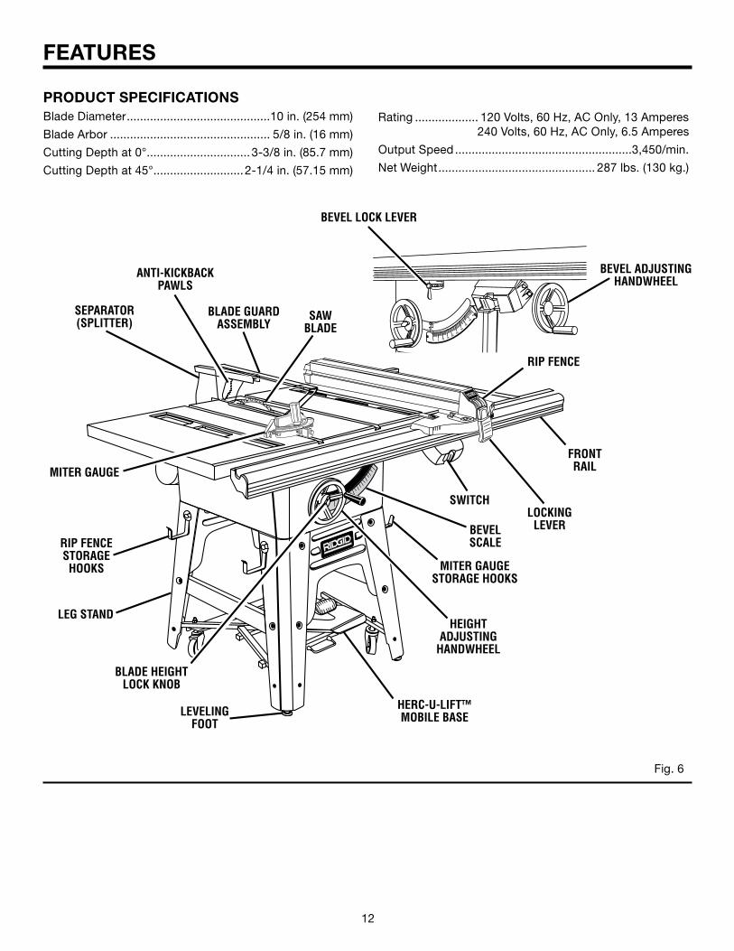
PRODUCT SPECIFICATIONSBlade Diameter...........................................10 in. (254 mm)
Blade Arbor ................................................ 5/8 in. (16 mm)
Cutting Depth at 0°...............................3-3/8 in. (85.7 mm)
Cutting Depth at 45°...........................2-1/4 in. (57.15 mm)
Rating ................... 120 Volts, 60 Hz, AC Only, 13 Amperes 240 Volts, 60 Hz, AC Only, 6.5 Amperes
Output Speed.....................................................3,450/min.
Net Weight............................................... 287 lbs. (130 kg.)
12 13
FEATURES
BLADE GUARD - Always keep the guard down over the blade for through-sawing cuts.
BLADE HEIGHT LOCK KNOB - This knob, in the center of the height adjusting handwheel, locks the handwheel into place and must be unlocked before turning the handwheel.
BEVEL LOCK LEVER - This lever, placed just under the worktable surface on the front of the cabinet, locks the angle setting of the blade. Be sure the lever is unlocked before tilting the blade. If it is not unlocked, it may jam and bend the locking bolt.
HEIGHT ADJUSTING HANDWHEEL - Use this handwheel to lower and raise the blade for adjustments or replacement. It is located on the front of the cabinet.
HERC-U-LIFT MOBILE BASETM - This saw comes with a mobile base that allows for easy mobility.
IND-I-CUT™ ALIGNMENT DISC - A plastic insert on which marks may be made to indicate the location of the cut on the workpiece.
LOCKING LEVER - The lever on the front of the rip fence releases the rip fence or locks it in place.
MITER GAUGE - This miter gauge aligns the wood for a crosscut. The easy-to-read indicator shows the exact angle for a miter cut, with positive stops at 90° and 45°.
MITER GAUGE GROOVES - The miter gauge rides in these grooves on either side of the blade.
MOTOR - The powerful induction motor, with capacitor start and poly V-belt drive, is housed in a sturdy steel base.
RAILS - Front and rear rails provide support for the rip fence and extension tables.
RIP FENCE - A sturdy metal fence guides the workpiece and is secured with the locking lever. Grooves run along the top and sides of the rip fence for use with clamps and jigs.
SCALE - Found on the front rail, the easy-to-read scale provides precise measurements in rip cuts.
SEPARATOR OR SPLITTER - A metal piece, slightly thin-ner than the saw blade which helps keep the kerf open and prevent kickback.
SWITCH ASSEMBLY - Your table saw has an easy access power switch located below the front rail. The yellow switch key must be removed from the blister pack and inserted into the switch before the saw can be operated. To lock the switch in the OFF position, remove the switch key from the switch. Place the key in a location that is inaccessible to children and others not qualified to use the tool.
KNOW YOUR TABLE SAWSee Figure 6.
Before attempting to use this product, familiarize yourself with all operating features and safety rules.
OVERVIEWThe upper portion of the blade projects up through the table, surrounded by an insert called the throat plate. The height of the blade is set with a height adjusting handwheel on the front of the cabinet. Detailed instructions are provided in the Operation section of this manual for the basic cuts: rip cuts, cross cuts, miter cuts, bevel cuts, and compound cuts.
For cuts with the blade straight up and cutting across the grain (cross cuts or miter cuts), use the miter gauge to set the angle and push the wood into the blade. To cut with the blade straight up, along the grain of the wood (rip cuts), use the rip fence to guide the wood. Push smaller pieces with a push block or push stick.
To tilt the blade for a bevel cut, use the bevel adjusting hand-wheel on the side of the cabinet. A bevel scale on the front of the cabinet shows the blade angle. Inside the cabinet, adjustable positive stops control the degree of tilt which can be adjusted with the screws in the top of the saw table. Use the miter gauge for a bevel cross cut (compound cut) and the rip fence for a bevel rip cut.
Your saw is designed to perform as a versatile, accurate, precision cutting tool that is easy to operate. It is equipped with the following features for convenience, ease of use, and high-quality performance:
ANTI-KICKBACK PAWLS - Kickback is a hazard in which the workpiece is thrown back toward the operator. The toothed pawls are designed to snag the workpiece to prevent or reduce injury should kickback occur.
BEVEL ADJUSTING HANDWHEEL - Use this handwheel to set the angle of the blade for bevel cuts. It is located on the side of the cabinet.
BEVEL SCALE - The easy-to-read scale on the front of the workstand shows the exact blade angle.
BLADE - For maximum performance, it is recommended that you use the 40-tooth, 10 in. (254 mm) carbide tipped combination blade provided with your saw. Additional blade styles of the same high quality are available for specific op-erations such as ripping. Your local dealer can provide you with complete information.
WARNING:Do not use blades rated less than the speed of this tool. Failure to heed this warning could result in personal injury.
14 15
TOOLS NEEDED
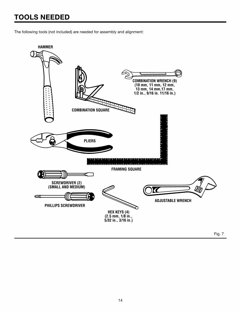
The following tools (not included) are needed for assembly and alignment:
COMBINATION WRENCH (9) (10 mm, 11 mm, 12 mm,13 mm, 14 mm,17 mm,
1/2 in., 9/16 in. 11/16 in.)
FRAMING SQUARE
Fig. 7
PLIERS
HAMMER
PHILLIPS SCREWDRIVER
SCREWDRIVER (2) (SMALL AND MEDIUM)
ADJUSTABLE WRENCH
HEX KEYS (4)(2.5 mm, 1/8 in., 5/32 in., 3/16 in.)
COMBINATION SQUARE
14 15
®
LOOSE PARTS LIST
Fig. 8
KeyNo. Description Qty.
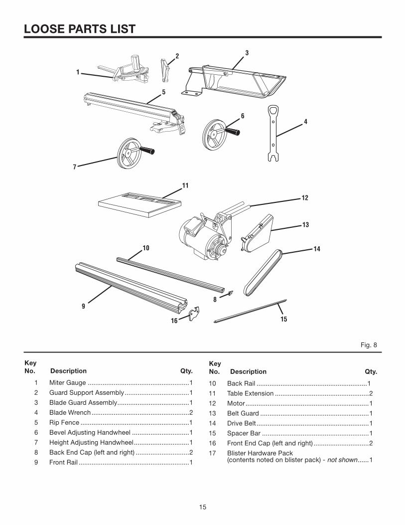
1 Miter Gauge .......................................................1
2 Guard Support Assembly...................................1
3 Blade Guard Assembly.......................................1
4 Blade Wrench.....................................................2
5 Rip Fence ...........................................................1
6 Bevel Adjusting Handwheel ...............................1
7 Height Adjusting Handwheel..............................1
8 Back End Cap (left and right) .............................2
9 Front Rail ............................................................1
1
3
4
2
6
11
7
9
KeyNo. Description Qty.
10
15
12
14
13
16
8
10 Back Rail ............................................................1
11 Table Extension ...................................................2
12 Motor...................................................................1
13 Belt Guard ...........................................................1
14 Drive Belt.............................................................1
15 Spacer Bar ..........................................................1
16 Front End Cap (left and right) ..............................2
17 Blister Hardware Pack (contents noted on blister pack) - not shown ......1
5
16 17
LOOSE PARTS LIST
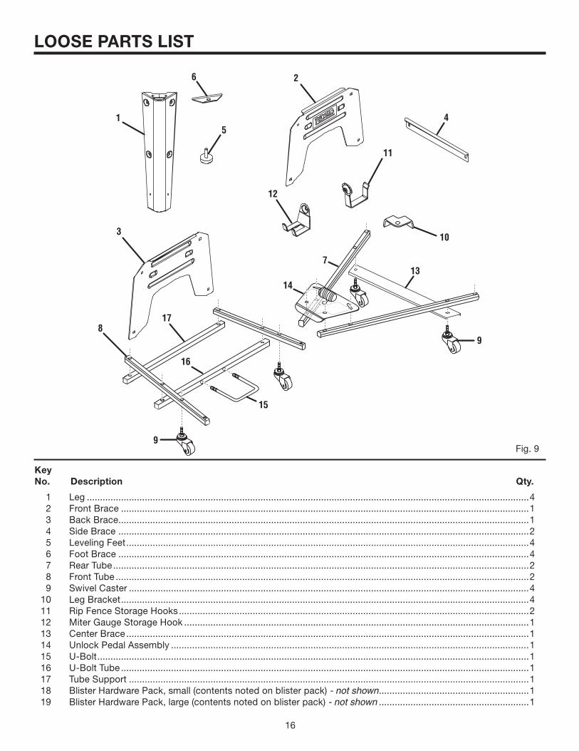
1 Leg ........................................................................................................................................................................4 2 Front Brace ...........................................................................................................................................................1 3 Back Brace............................................................................................................................................................1 4 Side Brace ............................................................................................................................................................2 5 Leveling Feet.........................................................................................................................................................4 6 Foot Brace ............................................................................................................................................................4 7 Rear Tube..............................................................................................................................................................2 8 Front Tube .............................................................................................................................................................2 9 Swivel Caster ........................................................................................................................................................4 10 Leg Bracket...........................................................................................................................................................4 11 Rip Fence Storage Hooks.....................................................................................................................................2 12 Miter Gauge Storage Hook ...................................................................................................................................1 13 Center Brace.........................................................................................................................................................1 14 Unlock Pedal Assembly ........................................................................................................................................1 15 U-Bolt....................................................................................................................................................................1 16 U-Bolt Tube...........................................................................................................................................................1 17 Tube Support ........................................................................................................................................................1 18 Blister Hardware Pack, small (contents noted on blister pack) - not shown.........................................................1 19 Blister Hardware Pack, large (contents noted on blister pack) - not shown .........................................................1
KeyNo. Description Qty.
Fig. 9
1
2
3
13
6
5
7
8
10
12
11
9
14
15
9
17
16
4
16 17
ASSEMBLY
UNPACKINGThis product requires assembly.n Remove the packing materials from around your tool. Do
not discard the packing material until you have carefully inspected and satisfactorily operated the tool.
n Separate and remove all loose parts from the carton. Check parts against the list of loose parts.
n Carefully lift the tool from the carton and place it on a level work surface.
NOTE: This tool is heavy. To avoid back injury, lift with your legs, not your back, and get help when needed.
n Remove the protective oil that is applied to all unpainted metal surfaces. Use any ordinary household type grease and spot remover.
n Apply coat of paste wax to the table and table extensions.n Inspect the tool carefully to make sure no breakage or
damage occurred during shipping.n The saw is factory set for accurate cutting. After assem-
bling it, check for accuracy. If shipping has influenced the settings, refer to specific procedures explained in this manual.
n If any parts are damaged or missing, please call1-866-539-1710 for assistance.
WARNING:If any parts are missing do not operate this tool until the missing parts are replaced. Failure to do so could result in possible serious personal injury.
WARNING:Do not connect to power supply until assembly iscomplete. Failure to comply could result in ac-cidental starting and possible serious personal injury.
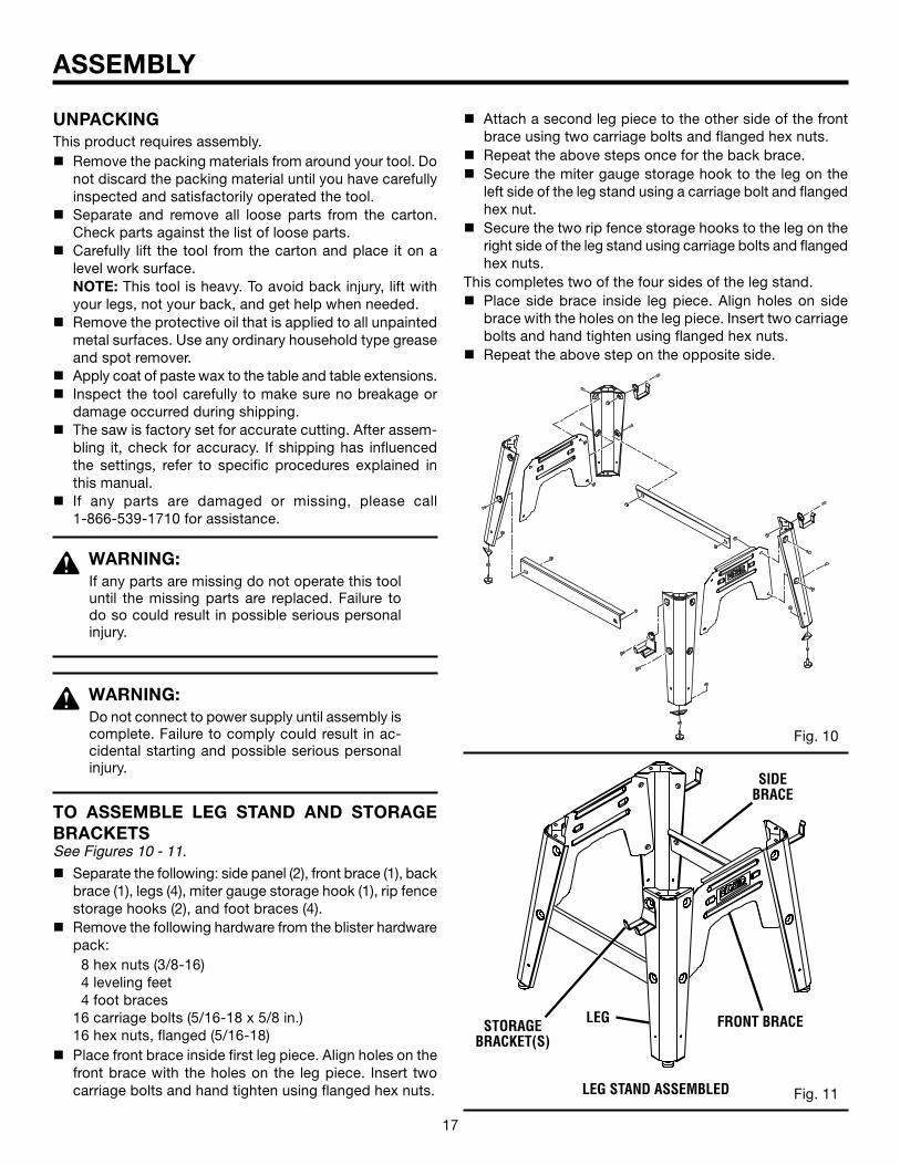
TO ASSEMBLE LEG STAND AND STORAGE BRACKETSSee Figures 10 - 11.
n Separate the following: side panel (2), front brace (1), back brace (1), legs (4), miter gauge storage hook (1), rip fence storage hooks (2), and foot braces (4).
n Remove the following hardware from the blister hardware pack:
8 hex nuts (3/8-16) 4 leveling feet 4 foot braces 16 carriage bolts (5/16-18 x 5/8 in.) 16 hex nuts, flanged (5/16-18)n Place front brace inside first leg piece. Align holes on the
front brace with the holes on the leg piece. Insert two carriage bolts and hand tighten using flanged hex nuts.
Fig. 10
Fig. 11LEG STAND ASSEMBLED
LEG FRONT BRACE
SIDE BRACE
STORAGE BRACKET(S)
n Attach a second leg piece to the other side of the front brace using two carriage bolts and flanged hex nuts.
n Repeat the above steps once for the back brace.n Secure the miter gauge storage hook to the leg on the
left side of the leg stand using a carriage bolt and flanged hex nut.
n Secure the two rip fence storage hooks to the leg on the right side of the leg stand using carriage bolts and flanged hex nuts.
This completes two of the four sides of the leg stand.n Place side brace inside leg piece. Align holes on side
brace with the holes on the leg piece. Insert two carriage bolts and hand tighten using flanged hex nuts.
n Repeat the above step on the opposite side.
18 19
ASSEMBLY
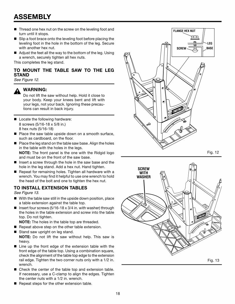
n Thread one hex nut on the screw on the leveling foot and turn until it stops.
n Slip a foot brace onto the leveling foot before placing the leveling foot in the hole in the bottom of the leg. Secure with another hex nut.
n Adjust the feet all the way to the bottom of the leg. Using a wrench, securely tighten all hex nuts.
This completes the leg stand.
TO MOUNT THE TABLE SAW TO THE LEG STANDSee Figure 12.
WARNING:Do not lift the saw without help. Hold it close to your body. Keep your knees bent and lift with your legs, not your back. Ignoring these precau-tions can result in back injury.
n Locate the following hardware: 8 screws (5/16-18 x 5/8 in.) 8 hex nuts (5/16-18)n Place the saw table upside down on a smooth surface,
such as cardboard, on the floor. n Place the leg stand on the table saw base. Align the holes
in the table with the holes in the legs. NOTE: The front panel is the one with the Ridgid logo
and must be on the front of the saw base.n Insert a screw through the hole in the saw base and the
hole in the leg stand. Add a hex nut. Hand tighten.n Repeat for remaining holes. Tighten all hardware with a
wrench. You may find it helpful to use one wrench to hold the head of the bolt and one to tighten the hex nut.
TO INSTALL EXTENSION TABLESSee Figure 13.
n With the table saw still in the upside down position, place a table extension against the table top.
n Insert four screws (5/16-18 x 3/4 in. with washer) through the holes in the table extension and screw into the table top. Do not tighten.
NOTE: The holes in the table top are threaded.n Repeat above step on the other table extension.n Stand saw upright on leg stand. NOTE: Do not lift the saw without help. This saw is
heavy.n Line up the front edge of the extension table with the
front edge of the table top. Using a combination square, check the alignment of the table top edge to the extension rail edge. Tighten the two corner nuts only with a 1/2 in. wrench.
n Check the center of the table top and extension table. If necessary, use a C-clamp to align the edges. Tighten the center nuts with a 1/2 in. wrench.
n Repeat steps for the other extension table.
Fig. 13
®
Fig. 12
®
SCREW WITH
WASHER
18 19
ASSEMBLY
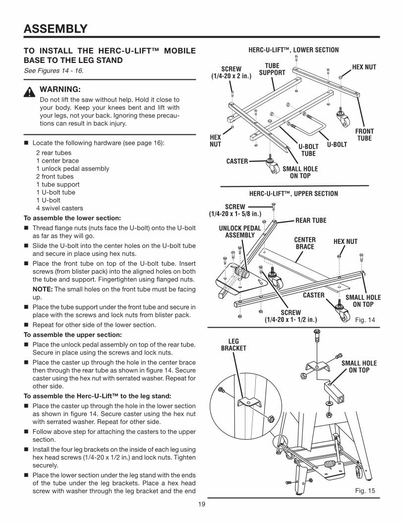
TO INSTALL THE HERC-U-LIFT™ MOBILE BASE TO THE LEG STANDSee Figures 14 - 16.
WARNING:Do not lift the saw without help. Hold it close to your body. Keep your knees bent and lift with your legs, not your back. Ignoring these precau-tions can result in back injury.
n Locate the following hardware (see page 16):
2 rear tubes 1 center brace 1 unlock pedal assembly 2 front tubes 1 tube support 1 U-bolt tube 1 U-bolt 4 swivel casters
To assemble the lower section:
n Thread flange nuts (nuts face the U-bolt) onto the U-bolt as far as they will go.
n Slide the U-bolt into the center holes on the U-bolt tube and secure in place using hex nuts.
n Place the front tube on top of the U-bolt tube. Insert screws (from blister pack) into the aligned holes on both the tube and support. Fingertighten using flanged nuts.
NOTE: The small holes on the front tube must be facing up.
n Place the tube support under the front tube and secure in place with the screws and lock nuts from blister pack.
n Repeat for other side of the lower section.
To assemble the upper section:
n Place the unlock pedal assembly on top of the rear tube. Secure in place using the screws and lock nuts.
n Place the caster up through the hole in the center brace then through the rear tube as shown in figure 14. Secure caster using the hex nut with serrated washer. Repeat for other side.
To assemble the Herc-U-Lift™ to the leg stand:
n Place the caster up through the hole in the lower section as shown in figure 14. Secure caster using the hex nut with serrated washer. Repeat for other side.
n Follow above step for attaching the casters to the upper section.
n Install the four leg brackets on the inside of each leg using hex head screws (1/4-20 x 1/2 in.) and lock nuts. Tighten securely.
n Place the lower section under the leg stand with the ends of the tube under the leg brackets. Place a hex head screw with washer through the leg bracket and the end
CASTER
Fig. 14
Fig. 15
LEG BRACKET
HERC-U-LIFT™, LOWER SECTION
HERC-U-LIFT™, UPPER SECTION
UNLOCK PEDAL ASSEMBLY
SMALL HOLE ON TOP
SMALL HOLE ON TOP
SMALL HOLE ON TOP
HEX NUT
U-BOLT
TUBE SUPPORT
FRONT TUBE
CENTER BRACE
CASTER
REAR TUBE
HEX NUT
HEX NUT
SCREW(1/4-20 x 1- 5/8 in.)
SCREW(1/4-20 x 2 in.)
U-BOLTTUBE
SCREW(1/4-20 x 1- 1/2 in.)
20 21
ASSEMBLY
Fig. 16
Fig. 17
Fig. 18
UNLOCK PEDAL
CENTER U-BOLT WITHIN THE LATCH MECHANISM
®
0 5 1015
2025
30
35
40
45
®
0 5 1015
2025
30
35
40
45
HEIGHT ADJUSTING
HANDWHEEL
BEVEL ADJUSTING
HANDWHEEL
LOCK TUBEBLADE
HEIGHT LOCK KNOB
SCREW
of the tube of the lower section as shown in figure 15. Secure using the flat washer and lock nut.
NOTE: Tighten the lock nuts until flush with the bottom of the screw. The screw should freely pivot.
n Repeat above step for the upper section of the Herc-U-Lift™.
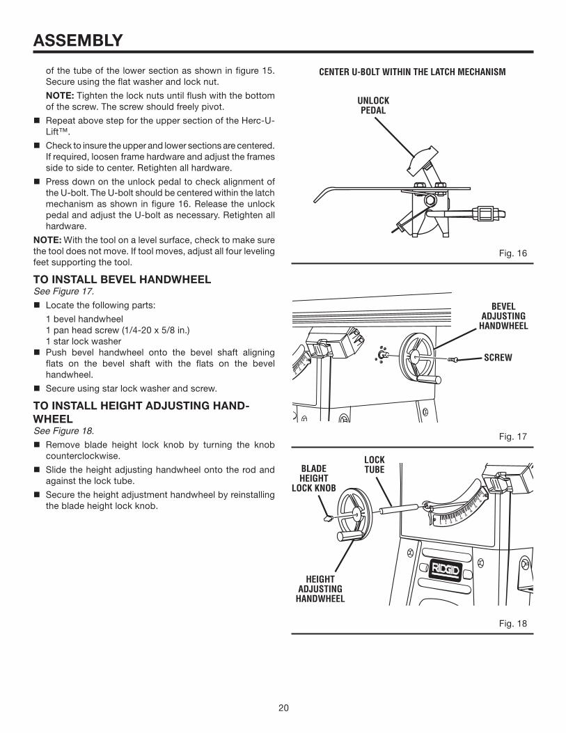
n Check to insure the upper and lower sections are centered. If required, loosen frame hardware and adjust the frames side to side to center. Retighten all hardware.
n Press down on the unlock pedal to check alignment of the U-bolt. The U-bolt should be centered within the latch mechanism as shown in figure 16. Release the unlock pedal and adjust the U-bolt as necessary. Retighten all hardware.
NOTE: With the tool on a level surface, check to make sure the tool does not move. If tool moves, adjust all four leveling feet supporting the tool.
TO INSTALL BEVEL HANDWHEELSee Figure 17.
n Locate the following parts:
1 bevel handwheel 1 pan head screw (1/4-20 x 5/8 in.) 1 star lock washer n Push bevel handwheel onto the bevel shaft aligning
flats on the bevel shaft with the flats on the bevel handwheel.
n Secure using star lock washer and screw.
TO INSTALL HEIGHT ADJUSTING HAND-WHEELSee Figure 18.
n Remove blade height lock knob by turning the knob counterclockwise.
n Slide the height adjusting handwheel onto the rod and against the lock tube.
n Secure the height adjustment handwheel by reinstalling the blade height lock knob.
20 21
ASSEMBLY
Fig. 19
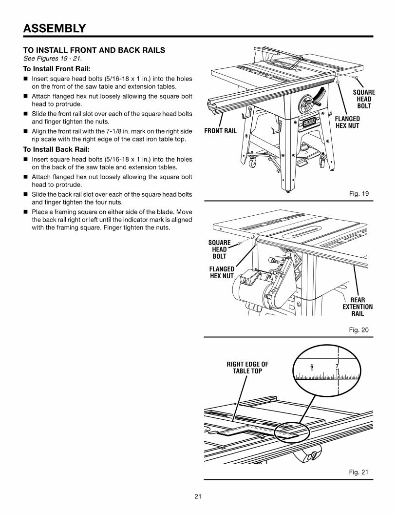
TO INSTALL FRONT AND BACK RAILSSee Figures 19 - 21.
To Install Front Rail:n Insert square head bolts (5/16-18 x 1 in.) into the holes
on the front of the saw table and extension tables.
n Attach flanged hex nut loosely allowing the square bolt head to protrude.
n Slide the front rail slot over each of the square head bolts and finger tighten the nuts.
n Align the front rail with the 7-1/8 in. mark on the right side rip scale with the right edge of the cast iron table top.
To Install Back Rail:n Insert square head bolts (5/16-18 x 1 in.) into the holes
on the back of the saw table and extension tables.
n Attach flanged hex nut loosely allowing the square bolt head to protrude.
n Slide the back rail slot over each of the square head bolts and finger tighten the four nuts.
n Place a framing square on either side of the blade. Move the back rail right or left until the indicator mark is aligned with the framing square. Finger tighten the nuts.
Fig. 20
®
Fig. 21
SQUARE HEAD BOLT
FLANGED HEX NUT
FRONT RAIL
SQUARE HEAD BOLT
FLANGED HEX NUT
REAR EXTENTION
RAIL
®
6 7RIGHT EDGE OF TABLE TOP
22 23
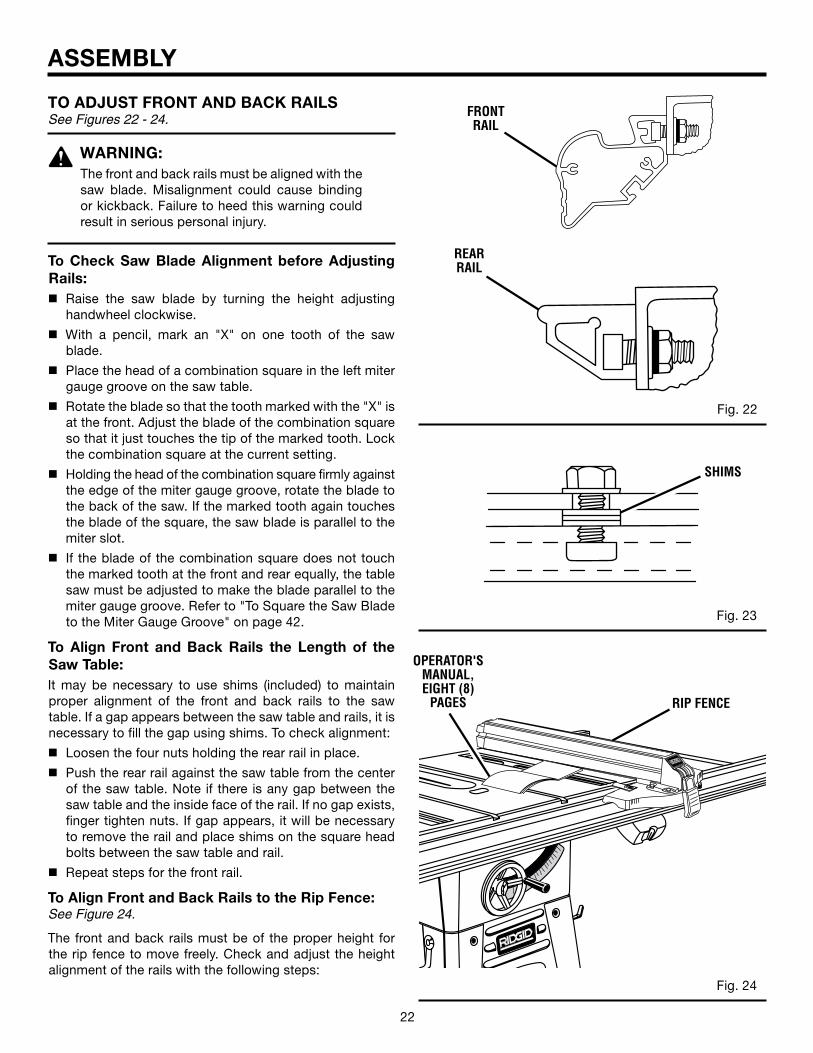
TO ADJUST FRONT AND BACK RAILS See Figures 22 - 24.
WARNING:The front and back rails must be aligned with the saw blade. Misalignment could cause binding or kickback. Failure to heed this warning could result in serious personal injury.
To Check Saw Blade Alignment before Adjusting Rails:n Raise the saw blade by turning the height adjusting
handwheel clockwise.
n With a pencil, mark an "X" on one tooth of the saw blade.
n Place the head of a combination square in the left miter gauge groove on the saw table.
n Rotate the blade so that the tooth marked with the "X" is at the front. Adjust the blade of the combination square so that it just touches the tip of the marked tooth. Lock the combination square at the current setting.
n Holding the head of the combination square firmly against the edge of the miter gauge groove, rotate the blade to the back of the saw. If the marked tooth again touches the blade of the square, the saw blade is parallel to the miter slot.
n If the blade of the combination square does not touch the marked tooth at the front and rear equally, the table saw must be adjusted to make the blade parallel to the miter gauge groove. Refer to "To Square the Saw Blade to the Miter Gauge Groove" on page 42.
To Align Front and Back Rails the Length of the Saw Table:It may be necessary to use shims (included) to maintain proper alignment of the front and back rails to the saw table. If a gap appears between the saw table and rails, it is necessary to fill the gap using shims. To check alignment:
n Loosen the four nuts holding the rear rail in place.
n Push the rear rail against the saw table from the center of the saw table. Note if there is any gap between the saw table and the inside face of the rail. If no gap exists, finger tighten nuts. If gap appears, it will be necessary to remove the rail and place shims on the square head bolts between the saw table and rail.
n Repeat steps for the front rail.
To Align Front and Back Rails to the Rip Fence:See Figure 24.
The front and back rails must be of the proper height for the rip fence to move freely. Check and adjust the height alignment of the rails with the following steps:
ASSEMBLY
Fig. 22
Fig. 23
Fig. 24
REAR RAIL
FRONT RAIL
®
®
SHIMS
RIP FENCE
OPERATOR'S MANUAL, EIGHT (8)
PAGES
22 23
ASSEMBLY
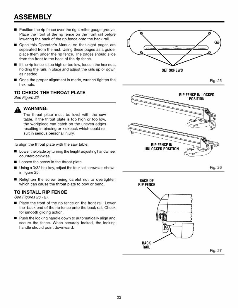
n Position the rip fence over the right miter gauge groove. Place the front of the rip fence on the front rail before lowering the back of the rip fence onto the back rail.
n Open this Operator's Manual so that eight pages are separated from the rest. Using these pages as a guide, place them under the rip fence. The pages should slide from the front to the back of the rip fence.
n If the rip fence is too high or too low, loosen the hex nuts holding the rails in place and adjust the rails up or down as needed.
n Once the proper alignment is made, wrench tighten the hex nuts.
TO CHECK THE THROAT PLATESee Figure 25.
WARNING:The throat plate must be level with the saw table. If the throat plate is too high or too low, the workpiece can catch on the uneven edges resulting in binding or kickback which could re-sult in serious personal injury.
To align the throat plate with the saw table:
n Lower the blade by turning the height adjusting handwheel counterclockwise.
n Loosen the screw in the throat plate.
n Using a 3/32 hex key, adjust the four set screws as shown in figure 25.
n Retighten the screw being careful not to overtighten which can cause the throat plate to bow or bend.
TO INSTALL RIP FENCESee Figures 26 - 27.
n Place the front of the rip fence on the front rail. Lower the back end of the rip fence onto the back rail. Check for smooth gliding action.
n Push the locking handle down to automatically align and secure the fence. When securely locked, the locking handle should point downward.
Fig. 25
Fig. 26
Fig. 27
®
®
BACK RAIL
RIP FENCE IN LOCKED POSITION
RIP FENCE IN UNLOCKED POSITION
BACK OF RIP FENCE
SET SCREWS
24 25
Fig. 28
ASSEMBLY
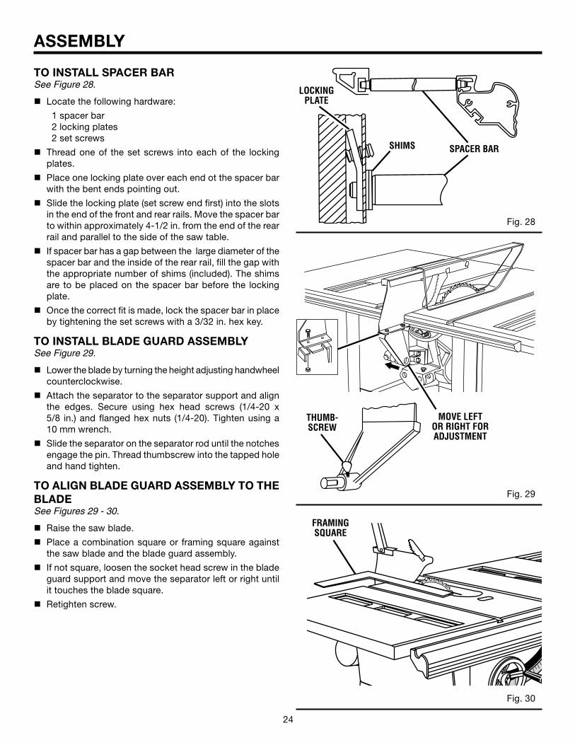
TO INSTALL SPACER BARSee Figure 28.
n Locate the following hardware:
1 spacer bar 2 locking plates 2 set screws
n Thread one of the set screws into each of the locking plates.
n Place one locking plate over each end ot the spacer bar with the bent ends pointing out.
n Slide the locking plate (set screw end first) into the slots in the end of the front and rear rails. Move the spacer bar to within approximately 4-1/2 in. from the end of the rear rail and parallel to the side of the saw table.
n If spacer bar has a gap between the large diameter of the spacer bar and the inside of the rear rail, fill the gap with the appropriate number of shims (included). The shims are to be placed on the spacer bar before the locking plate.
n Once the correct fit is made, lock the spacer bar in place by tightening the set screws with a 3/32 in. hex key.
TO INSTALL BLADE GUARD ASSEMBLYSee Figure 29.
n Lower the blade by turning the height adjusting handwheel counterclockwise.
n Attach the separator to the separator support and align the edges. Secure using hex head screws (1/4-20 x 5/8 in.) and flanged hex nuts (1/4-20). Tighten using a 10 mm wrench.
n Slide the separator on the separator rod until the notches engage the pin. Thread thumbscrew into the tapped hole and hand tighten.
TO ALIGN BLADE GUARD ASSEMBLY TO THE BLADESee Figures 29 - 30.
n Raise the saw blade.
n Place a combination square or framing square against the saw blade and the blade guard assembly.
n If not square, loosen the socket head screw in the blade guard support and move the separator left or right until it touches the blade square.
n Retighten screw.
Fig. 29
Fig. 30
®
SHIMS SPACER BAR
LOCKING PLATE
THUMB- SCREW
MOVE LEFT OR RIGHT FOR ADJUSTMENT
FRAMING SQUARE
24 25
Fig. 31
Fig. 32
ASSEMBLY
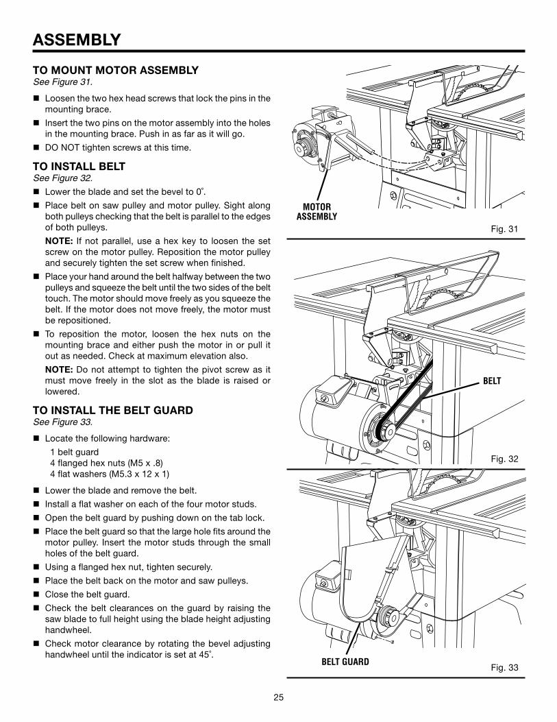
TO MOUNT MOTOR ASSEMBLYSee Figure 31.
n Loosen the two hex head screws that lock the pins in the mounting brace.
n Insert the two pins on the motor assembly into the holes in the mounting brace. Push in as far as it will go.
n DO NOT tighten screws at this time.
TO INSTALL BELTSee Figure 32.
n Lower the blade and set the bevel to 0˚.
n Place belt on saw pulley and motor pulley. Sight along both pulleys checking that the belt is parallel to the edges of both pulleys.
NOTE: If not parallel, use a hex key to loosen the set screw on the motor pulley. Reposition the motor pulley and securely tighten the set screw when finished.
n Place your hand around the belt halfway between the two pulleys and squeeze the belt until the two sides of the belt touch. The motor should move freely as you squeeze the belt. If the motor does not move freely, the motor must be repositioned.
n To reposition the motor, loosen the hex nuts on the mounting brace and either push the motor in or pull it out as needed. Check at maximum elevation also.
NOTE: Do not attempt to tighten the pivot screw as it must move freely in the slot as the blade is raised or lowered.
TO INSTALL THE BELT GUARDSee Figure 33.
n Locate the following hardware:
1 belt guard 4 flanged hex nuts (M5 x .8) 4 flat washers (M5.3 x 12 x 1)
n Lower the blade and remove the belt.
n Install a flat washer on each of the four motor studs.
n Open the belt guard by pushing down on the tab lock.
n Place the belt guard so that the large hole fits around the motor pulley. Insert the motor studs through the small holes of the belt guard.
n Using a flanged hex nut, tighten securely.
n Place the belt back on the motor and saw pulleys.
n Close the belt guard.
n Check the belt clearances on the guard by raising the saw blade to full height using the blade height adjusting handwheel.
n Check motor clearance by rotating the bevel adjusting handwheel until the indicator is set at 45˚.
Fig. 33
MOTOR ASSEMBLY
BELT GUARD
BELT
26 27
Fig. 38
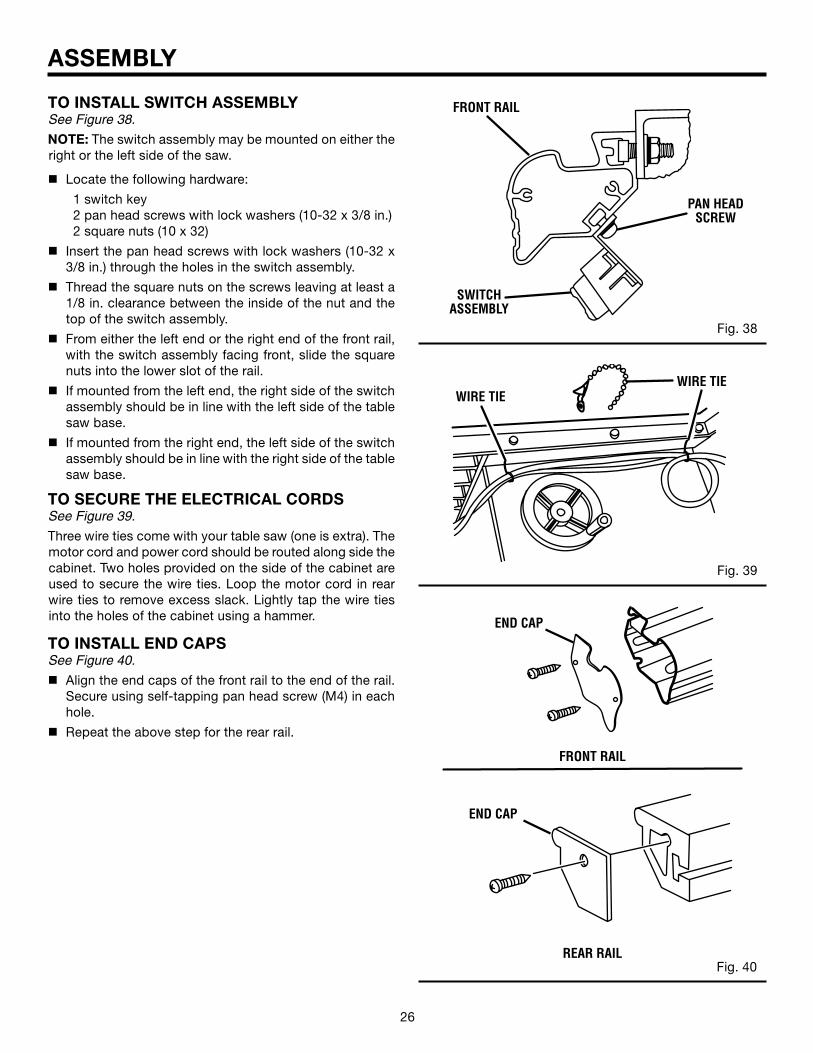
TO INSTALL SWITCH ASSEMBLYSee Figure 38.
NOTE: The switch assembly may be mounted on either the right or the left side of the saw.
n Locate the following hardware:
1 switch key 2 pan head screws with lock washers (10-32 x 3/8 in.) 2 square nuts (10 x 32)
n Insert the pan head screws with lock washers (10-32 x 3/8 in.) through the holes in the switch assembly.
n Thread the square nuts on the screws leaving at least a 1/8 in. clearance between the inside of the nut and the top of the switch assembly.
n From either the left end or the right end of the front rail, with the switch assembly facing front, slide the square nuts into the lower slot of the rail.
n If mounted from the left end, the right side of the switch assembly should be in line with the left side of the table saw base.
n If mounted from the right end, the left side of the switch assembly should be in line with the right side of the table saw base.
TO SECURE THE ELECTRICAL CORDSSee Figure 39.
Three wire ties come with your table saw (one is extra). The motor cord and power cord should be routed along side the cabinet. Two holes provided on the side of the cabinet are used to secure the wire ties. Loop the motor cord in rear wire ties to remove excess slack. Lightly tap the wire ties into the holes of the cabinet using a hammer.
TO INSTALL END CAPSSee Figure 40.
n Align the end caps of the front rail to the end of the rail. Secure using self-tapping pan head screw (M4) in each hole.
n Repeat the above step for the rear rail.
Fig. 39
Fig. 40
ASSEMBLY
END CAP
END CAP
PAN HEAD SCREW
FRONT RAIL
REAR RAIL
WIRE TIEWIRE TIE
SWITCH ASSEMBLY
FRONT RAIL

26 27
®
0 5 1015
2025
30
35
40
45
®
0 5 1015
2025
30
35
40
45
ASSEMBLY
TO ADJUST BLADE DEPTHSee Figure 41.
The saw blade depth should be set so that the outer points of the saw blade are higher than the workpiece by approximately 1/8 in. to 1/4 in. but the lowest points (gullets) are below the workpiece.
n Loosen the blade height lock knob by turning counter-clockwise.
n Raise the saw blade by turning the height adjusting handwheel clockwise or lower the saw blade by turning the height adjusting handwheel counterclockwise.
n Once the desired saw blade height is achieved, lock the blade height lock knob by turning it clockwise.
TO ADJUST BLADE ANGLESee Figure 42.
The saw blade angle is set by turning the bevel adjusting handwheel. Loosen the bevel lock lever then turn the bevel adjusting handwheel. Turning the handwheel clockwise will tilt the saw blade to the left; turning the handwheel counterclockwise will tilt the saw blade to the right.
n When the saw blade is tilted to the left as far as it will go, the blade should be at a 45˚ angle to the saw table and the bevel indicator should point to 45˚.
n When the saw blade is tilted to the right as far as it will go, the blade should be at 90˚ to the saw table and the bevel indicator should point to 0˚.
NOTE: When the saw blade is 90˚ to the saw table, the saw blade should be square with the saw table. (See the Adjustments section of this manual to square the saw blade.)
n Retighten the bevel lock lever.
NOTE: When locked, the bevel lock lever will keep the bevel adjusting handwheel locked securely in place to maintain blade angle.
Fig. 41
Fig. 42
BEVEL ADJUSTING HANDWHEEL
BEVEL LOCK LEVER
HEIGHT ADJUSTING
HANDWHEEL
BLADE HEIGHT LOCK KNOB
28 29
OPERATION
WARNING:Do not allow familiarity with tools to make you careless. Remember that a careless fraction of a second is sufficient to inflict serious injury.
WARNING:Always wear safety goggles or safety glasses with side shields when operating power tools. Failure to do so could result in objects being thrown into your eyes resulting in possible seri-ous injury.
WARNING:Do not use any attachments or accessories not recommended by the manufacturer of this tool. The use of attachments or accessories not recommended can result in serious personal injury.
APPLICATIONSYou may use this tool for the purposes listed below:
n Straight line cutting operations such as cross cutting, ripping, mitering, beveling, and compound cutting.
n Cabinet making and woodworking
BASIC OPERATION OF THE TABLE SAWA table saw can be used for straight-line cutting operations such as cross cutting, ripping, mitering, beveling, and compound cutting. It can make dado or molding cuts with optional accessories.
The 3-prong plug must be plugged into a matching outlet that is properly installed and grounded according to all local codes and ordinances. Improper connection of the equip-ment can result in electric shock. Check with an electrician or service personnel if you are unsure about proper grounding. Do not modify the plug; if it will not fit the outlet, have the correct outlet installed by a qualified electrician. Refer to the Electrical page of this manual.
NOTE: This table saw is designed to cut wood and wood composition products only. Do not use to cut other materials.
CAUSES OF KICKBACKKickback can occur when the blade stalls or binds, kicking the workpiece back toward you with great force and speed. If your hands are near the saw blade, they may be jerked loose from the workpiece and may contact the blade. Obviously, kickback can cause serious injury, and it is well worth using precautions to avoid the risks.
Kickback can be caused by any action that pinches the blade in the wood, such as the following:
n Making a cut with incorrect blade depth
n Sawing into knots or nails in the workpiece
n Twisting the wood while making a cut
n Failing to support work
n Forcing a cut
n Cutting warped or wet lumber
n Using the wrong blade for the type of cut
n Not following correct operating procedures
n Misusing the saw
n Failing to use the anti-kickback pawls
n Cutting with a dull, gummed-up, or improperly set blade
AVOIDING KICKBACKn Always use the correct blade depth setting. The top of
the blade teeth should clear the workpiece by 1/8 in. to 1/4 in.
n Inspect the work for knots or nails before beginning a cut. Knock out any loose knots with a hammer. Never saw into a loose knot or nail.
n Always use the rip fence when rip cutting and the miter gauge when cross cutting. This helps prevent twisting the wood in the cut.
n Always use clean, sharp, and properly-set blades. Never make cuts with dull blades.
n To avoid pinching the blade, support the work properly before beginning a cut.
n When making a cut, use steady, even pressure. Never force cuts.
n Do not cut wet or warped lumber.
n Always hold your workpiece firmly with both hands or with push sticks. Keep your body in a balanced position to be ready to resist kickback should it occur. Never stand directly in line with the blade.
n Use the right type of blade for the cut being made.
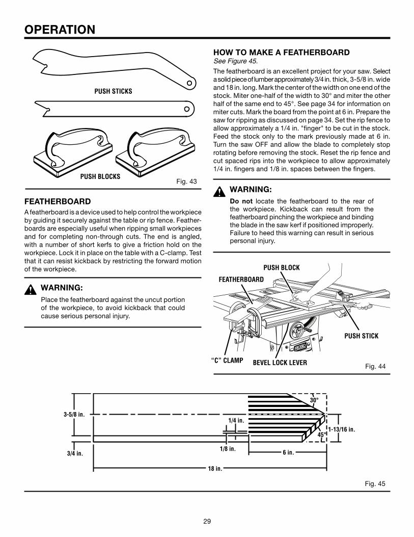
CUTTING AIDSSee Figure 43.
Push sticks are devices used for safely pushing a workpiece through the blade instead of using your hands. They can be made in various sizes and shapes from scrap wood to use in a specific project. The stick must be narrower than the workpiece, with a 90˚ notch in one end and shaping for a grip on the other end.
A push block has a handle fastened by recessed screws from the underside. Be sure the screw is recessed. Use it on non-through cuts.
28 29
Fig. 43PUSH BLOCKS
PUSH STICKS
OPERATION
FEATHERBOARDA featherboard is a device used to help control the workpiece by guiding it securely against the table or rip fence. Feather-boards are especially useful when ripping small workpieces and for completing non-through cuts. The end is angled, with a number of short kerfs to give a friction hold on the workpiece. Lock it in place on the table with a C-clamp. Test that it can resist kickback by restricting the forward motion of the workpiece.
WARNING: Place the featherboard against the uncut portion of the workpiece, to avoid kickback that could cause serious personal injury.
HOW TO MAKE A FEATHERBOARDSee Figure 45.
The featherboard is an excellent project for your saw. Select a solid piece of lumber approximately 3/4 in. thick, 3-5/8 in. wide and 18 in. long. Mark the center of the width on one end of the stock. Miter one-half of the width to 30° and miter the other half of the same end to 45°. See page 34 for information on miter cuts. Mark the board from the point at 6 in. Prepare the saw for ripping as discussed on page 34. Set the rip fence to allow approximately a 1/4 in. "finger" to be cut in the stock. Feed the stock only to the mark previously made at 6 in. Turn the saw OFF and allow the blade to completely stop rotating before removing the stock. Reset the rip fence and cut spaced rips into the workpiece to allow approximately 1/4 in. fingers and 1/8 in. spaces between the fingers.
WARNING:Do not locate the featherboard to the rear of the workpiece. Kickback can result from the featherboard pinching the workpiece and binding the blade in the saw kerf if positioned improperly. Failure to heed this warning can result in serious personal injury.
Fig. 44
Æ
Æ
PUSH BLOCK
“C” CLAMP
FEATHERBOARD
PUSH STICK
BEVEL LOCK LEVER
Fig. 45
1/8 in.
1/4 in.
3/4 in.
3-5/8 in.
1-13/16 in.
30°
45°
18 in.
6 in.
30 31
OPERATION
BEVEL RIP CUT
RIP CUT
CROSS CUT
MITER CUT
COMPOUND (BEVEL) MITER CUT
BEVEL CROSS CUT
1
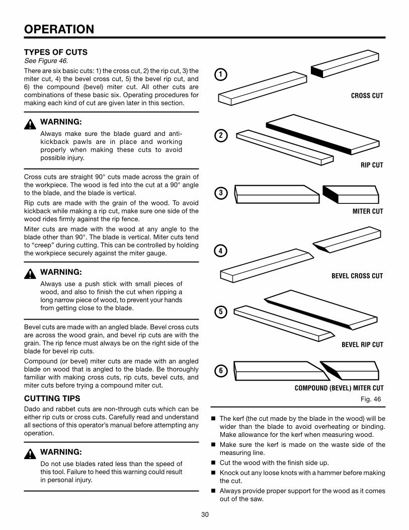
TYPES OF CUTSSee Figure 46.
There are six basic cuts: 1) the cross cut, 2) the rip cut, 3) the miter cut, 4) the bevel cross cut, 5) the bevel rip cut, and 6) the compound (bevel) miter cut. All other cuts arecombinations of these basic six. Operating procedures for making each kind of cut are given later in this section.
WARNING:Always make sure the blade guard and anti-kickback pawls are in place and working properly when making these cuts to avoid possible injury.
Cross cuts are straight 90° cuts made across the grain of the workpiece. The wood is fed into the cut at a 90° angle to the blade, and the blade is vertical.
Rip cuts are made with the grain of the wood. To avoid kickback while making a rip cut, make sure one side of the wood rides firmly against the rip fence.
Miter cuts are made with the wood at any angle to the blade other than 90°. The blade is vertical. Miter cuts tend to “creep” during cutting. This can be controlled by holding the workpiece securely against the miter gauge.
WARNING: Always use a push stick with small pieces of wood, and also to finish the cut when ripping a long narrow piece of wood, to prevent your hands from getting close to the blade.
Bevel cuts are made with an angled blade. Bevel cross cuts are across the wood grain, and bevel rip cuts are with the grain. The rip fence must always be on the right side of the blade for bevel rip cuts.
Compound (or bevel) miter cuts are made with an angled blade on wood that is angled to the blade. Be thoroughly familiar with making cross cuts, rip cuts, bevel cuts, and miter cuts before trying a compound miter cut.
CUTTING TIPSDado and rabbet cuts are non-through cuts which can be either rip cuts or cross cuts. Carefully read and understand all sections of this operator’s manual before attempting any operation.
WARNING:Do not use blades rated less than the speed of this tool. Failure to heed this warning could result in personal injury.
2
6
4
5
3
n The kerf (the cut made by the blade in the wood) will be wider than the blade to avoid overheating or binding. Make allowance for the kerf when measuring wood.
n Make sure the kerf is made on the waste side of the measuring line.
n Cut the wood with the finish side up.
n Knock out any loose knots with a hammer before making the cut.
n Always provide proper support for the wood as it comes out of the saw.
Fig. 46
30 31
OPERATION
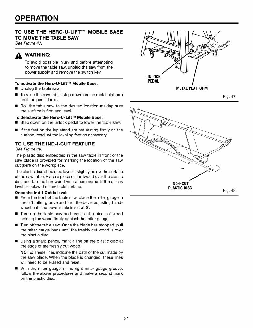
TO USE THE HERC-U-LIFT™ MOBILE BASE TO MOVE THE TABLE SAWSee Figure 47.
WARNING:To avoid possible injury and before attempting to move the table saw, unplug the saw from the power supply and remove the switch key.
To activate the Herc-U-Lift™ Mobile Base:n Unplug the table saw.
n To raise the saw table, step down on the metal platform until the pedal locks.
n Roll the table saw to the desired location making sure the surface is firm and level.
To deactivate the Herc-U-Lift™ Mobile Base:n Step down on the unlock pedal to lower the table saw.
n If the feet on the leg stand are not resting firmly on the surface, readjust the leveling feet as necessary.
TO USE THE IND-I-CUT FEATURESee Figure 48.
The plastic disc embedded in the saw table in front of the saw blade is provided for marking the location of the saw cut (kerf) on the workpiece.
The plastic disc should be level or slightly below the surface of the saw table. Place a piece of hardwood over the plastic disc and tap the hardwood with a hammer until the disc is level or below the saw table surface.
Once the Ind-I-Cut is level:n From the front of the table saw, place the miter gauge in
the left miter groove and turn the bevel adjusting hand-wheel until the bevel scale is set at 0˚.
n Turn on the table saw and cross cut a piece of wood holding the wood firmly against the miter gauge.
n Turn off the table saw. Once the blade has stopped, pull the miter gauge back until the freshly cut wood is over the plastic disc.
n Using a sharp pencil, mark a line on the plastic disc at the edge of the freshly cut wood.
NOTE: These lines indicate the path of the cut made by the saw blade. When the blade is changed, these lines will need to be erased and reset.
n With the miter gauge in the right miter gauge groove, follow the above procedures and make a second mark on the plastic disc.
®
Fig. 47
UNLOCK PEDAL
METAL PLATFORM
Fig. 48
IND-I-CUT PLASTIC DISC
32 33
OPERATION
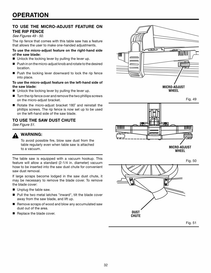
TO USE THE MICRO-ADJUST FEATURE ON THE RIP FENCESee Figures 49 - 50.
The rip fence that comes with this table saw has a feature that allows the user to make one-handed adjustments.
To use the micro-adjust feature on the right-hand side of the saw blade:n Unlock the locking lever by pulling the lever up.
n Push in on the micro-adjust knob and rotate to the desired location.
n Push the locking lever downward to lock the rip fence into place.
To use the micro-adjust feature on the left-hand side of the saw blade:n Unlock the locking lever by pulling the lever up.
n Turn the rip fence over and remove the two phillips screws on the micro-adjust bracket.
n Rotate the micro-adjust bracket 180˚ and reinstall the phillips screws. The rip fence is now set up to be used on the left-hand side of the saw blade.
TO USE THE SAW DUST CHUTESee Figure 51.
WARNING:To avoid possible fire, blow saw dust from the table regularly even when table saw is attached to a vacuum.
The table saw is equipped with a vacuum hookup. This feature will allow a standard (2-1/4 in. diameter) vacuum hose to be inserted into the saw dust chute for convenient saw dust removal.
lf large scraps become lodged in the saw dust chute, it may be necessary to remove the blade cover. To remove the blade cover:
n Unplug the table saw.
n Pull the two metal latches "inward", tilt the blade cover away from the saw blade, and lift up.
n Remove scraps of wood and blow any accumulated saw dust out of the area.
n Replace the blade cover.
Fig. 49
Fig. 50
Fig. 51
MICRO-ADJUST WHEEL
MICRO-ADJUST WHEEL
DUST CHUTE
32 33
OPERATION
MAKING CUTSThe blade provided with your saw is a high-quality combi-nation blade suitable for ripping and crosscut operations. Carefully check all setups and rotate the blade one full revolution to assure proper clearance before connecting saw to power source.
WARNING:Do not use blades rated less than the speed of this tool. Failure to heed this warning could result in personal injury.
Use the miter gauge when making cross, miter, bevel, and compound miter cuts. To secure the angle, lock the miter gauge in place by twisting the lock knob clockwise. Always tighten the lock knob securely in place when before use.
NOTE: It is recommended that you place the piece to be saved on the left side of the blade and that you make a test cut on scrap wood first.
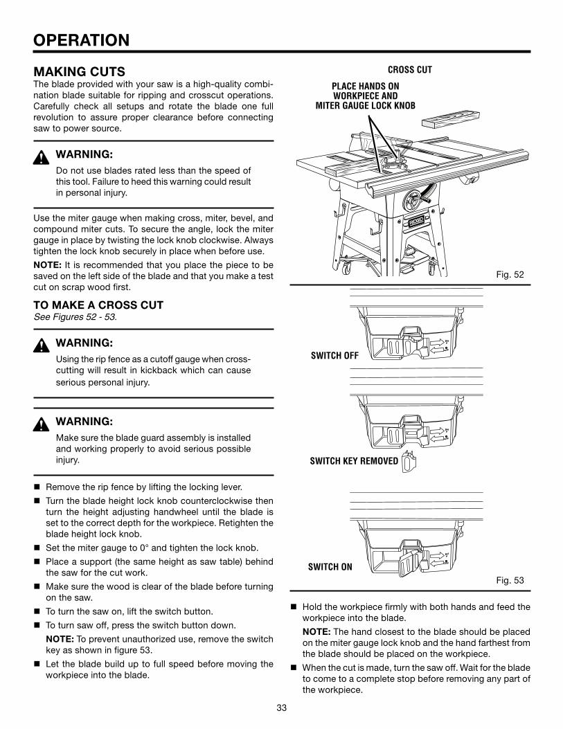
TO MAKE A CROSS CUTSee Figures 52 - 53.
WARNING:Using the rip fence as a cutoff gauge when cross-cutting will result in kickback which can cause serious personal injury.
WARNING:Make sure the blade guard assembly is installed and working properly to avoid serious possible injury.
n Remove the rip fence by lifting the locking lever.
n Turn the blade height lock knob counterclockwise then turn the height adjusting handwheel until the blade is set to the correct depth for the workpiece. Retighten the blade height lock knob.
n Set the miter gauge to 0° and tighten the lock knob.
n Place a support (the same height as saw table) behind the saw for the cut work.
n Make sure the wood is clear of the blade before turning on the saw.
n To turn the saw on, lift the switch button.
n To turn saw off, press the switch button down.
NOTE: To prevent unauthorized use, remove the switch key as shown in figure 53.
n Let the blade build up to full speed before moving the workpiece into the blade.
SWITCH OFF
SWITCH ON
SWITCH KEY REMOVED
PLACE HANDS ONWORKPIECE AND
MITER GAUGE LOCK KNOB
CROSS CUT
Æ
Fig. 53
Fig. 52
n Hold the workpiece firmly with both hands and feed the workpiece into the blade.
NOTE: The hand closest to the blade should be placed on the miter gauge lock knob and the hand farthest from the blade should be placed on the workpiece.
n When the cut is made, turn the saw off. Wait for the blade to come to a complete stop before removing any part of the workpiece.

34 35
Æ
Æ
Æ
OPERATION
TO MAKE A RIP CUTSee Figure 54.
WARNING: Make sure the blade guard assembly is installed and working properly to avoid serious possible injury.
n Turn the blade height lock knob counterclockwise then turn the height adjusting handwheel until the blade is set to the correct depth for the workpiece. Retighten the blade height lock knob.
n Set the blade to 0˚ (see "To Square the Saw Blade to the Miter Gauge Groove" in the Adjustments section).
n Position the rip fence the desired distance from the blade for the cut and securely lock the handle.
n Place a support (the same height as the saw table) behind the table saw for the cut work.
n Make sure the wood is clear of the blade before turning on the table saw.
n Use a push block or push stick to move the wood through the cut past the blade. Never push a small piece of wood into the blade with your hand, always use a push stick. The use of push blocks, push sticks, and featherboards are necessary when making non-through cuts.
n Stand to the side of the wood as it contacts the blade to reduce the chance of injury should kickback occur. Never stand directly in the line of cut.
n Make sure the wood is clear of the blade before turning on the table saw.
n Let the blade build up to full speed before feeding the workpiece into the blade.
n When the cut is made, turn the saw off. Wait for the blade to come to a complete stop before removing any part of the workpiece.
TO MAKE A MITER CUTSee Figure 55.
WARNING:Make sure the blade guard assembly is installed and working properly to avoid serious possible injury.
n Remove the rip fence by lifting the locking lever.
n Turn the blade height lock knob counterclockwise then turn the height adjusting handwheel until the blade is set to the correct depth for the workpiece. Retighten the blade height lock knob.
n Set miter gauge to desired angle and tighten bevel lock lever.
Fig. 54
MITER CUT
RIP CUT
BLADESTRAIGHT
MITER GAUGE ANGLED
BLADE
RIPFENCE
SCALE
HEIGHT ADJUSTING
HANDWHEEL
Fig. 55
n Place a support (the same height as saw table) behind the saw for the cut work.
n Make sure the wood is clear of the blade before turning on the saw.
n Let the blade build up to full speed before moving the workpiece into the blade.
n Hold the workpiece firmly with both hands and feed the workpiece into the blade.
NOTE: The hand closest to the blade should be placed on the miter gauge lock knob and the hand farthest from the blade should be placed on the workpiece.
n When the cut is made, turn the saw off. Wait for the blade to come to a complete stop before removing any part of the workpiece.
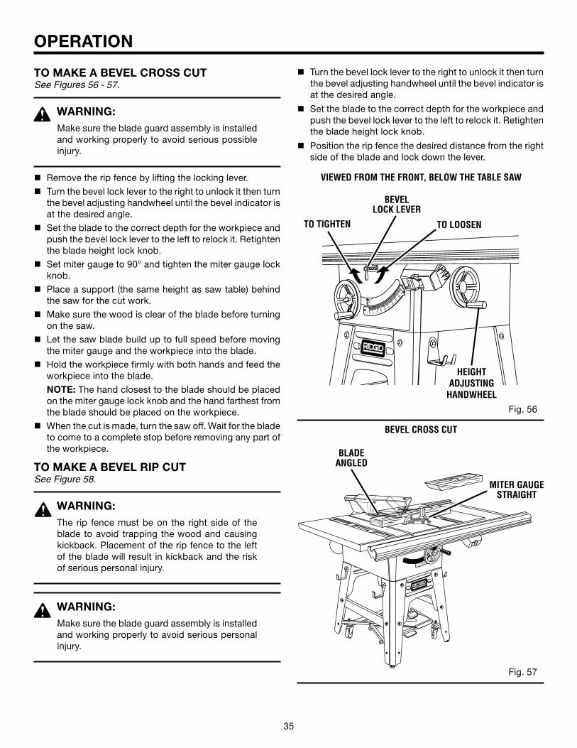
34 35
Æ
OPERATION
VIEWED FROM THE FRONT, BELOW THE TABLE SAW
BEVELLOCK LEVER
TO LOOSENTO TIGHTEN
HEIGHTADJUSTING
HANDWHEEL
TO MAKE A BEVEL CROSS CUTSee Figures 56 - 57.
WARNING:Make sure the blade guard assembly is installed and working properly to avoid serious possible injury.
n Remove the rip fence by lifting the locking lever.n Turn the bevel lock lever to the right to unlock it then turn
the bevel adjusting handwheel until the bevel indicator is at the desired angle.
n Set the blade to the correct depth for the workpiece and push the bevel lock lever to the left to relock it. Retighten the blade height lock knob.
n Set miter gauge to 90° and tighten the miter gauge lock knob.
n Place a support (the same height as saw table) behind the saw for the cut work.
n Make sure the wood is clear of the blade before turning on the saw.
n Let the saw blade build up to full speed before moving the miter gauge and the workpiece into the blade.
n Hold the workpiece firmly with both hands and feed the workpiece into the blade.
NOTE: The hand closest to the blade should be placed on the miter gauge lock knob and the hand farthest from the blade should be placed on the workpiece.
n When the cut is made, turn the saw off. Wait for the blade to come to a complete stop before removing any part of the workpiece.
TO MAKE A BEVEL RIP CUTSee Figure 58.
WARNING:The rip fence must be on the right side of the blade to avoid trapping the wood and causing kickback. Placement of the rip fence to the left of the blade will result in kickback and the risk of serious personal injury.
WARNING:Make sure the blade guard assembly is installed and working properly to avoid serious personal injury.
BEVEL CROSS CUT
BLADEANGLED
MITER GAUGESTRAIGHT
Fig. 56
Fig. 57
Æ
n Turn the bevel lock lever to the right to unlock it then turn the bevel adjusting handwheel until the bevel indicator is at the desired angle.
n Set the blade to the correct depth for the workpiece and push the bevel lock lever to the left to relock it. Retighten the blade height lock knob.
n Position the rip fence the desired distance from the right side of the blade and lock down the lever.
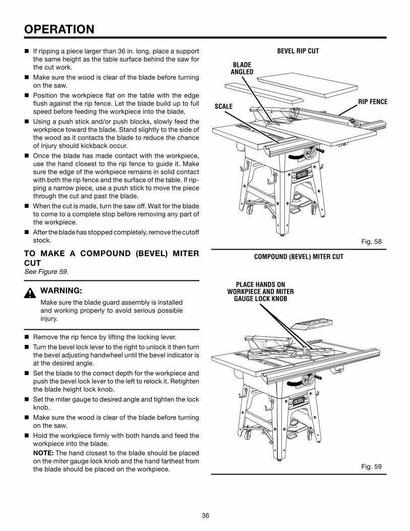
36 37
Æ
Æ
Æ
OPERATION
n If ripping a piece larger than 36 in. long, place a support the same height as the table surface behind the saw for the cut work.
n Make sure the wood is clear of the blade before turning on the saw.
n Position the workpiece flat on the table with the edge flush against the rip fence. Let the blade build up to full speed before feeding the workpiece into the blade.
n Using a push stick and/or push blocks, slowly feed the workpiece toward the blade. Stand slightly to the side of the wood as it contacts the blade to reduce the chance of injury should kickback occur.
n Once the blade has made contact with the workpiece, use the hand closest to the rip fence to guide it. Make sure the edge of the workpiece remains in solid contact with both the rip fence and the surface of the table. If rip-ping a narrow piece, use a push stick to move the piece through the cut and past the blade.
n When the cut is made, turn the saw off. Wait for the blade to come to a complete stop before removing any part of the workpiece.
n After the blade has stopped completely, remove the cutoff stock.
TO MAKE A COMPOUND (BEVEL) MITER CUTSee Figure 59.
WARNING:Make sure the blade guard assembly is installed and working properly to avoid serious possible injury.
n Remove the rip fence by lifting the locking lever.
n Turn the bevel lock lever to the right to unlock it then turn the bevel adjusting handwheel until the bevel indicator is at the desired angle.
n Set the blade to the correct depth for the workpiece and push the bevel lock lever to the left to relock it. Retighten the blade height lock knob.
n Set the miter gauge to desired angle and tighten the lock knob.
n Make sure the wood is clear of the blade before turning on the saw.
n Hold the workpiece firmly with both hands and feed the workpiece into the blade.
NOTE: The hand closest to the blade should be placed on the miter gauge lock knob and the hand farthest from the blade should be placed on the workpiece.
BEVEL RIP CUT
RIP FENCESCALE
BLADEANGLED
Fig. 58
Fig. 59
PLACE HANDS ON WORKPIECE AND MITER
GAUGE LOCK KNOB
COMPOUND (BEVEL) MITER CUT
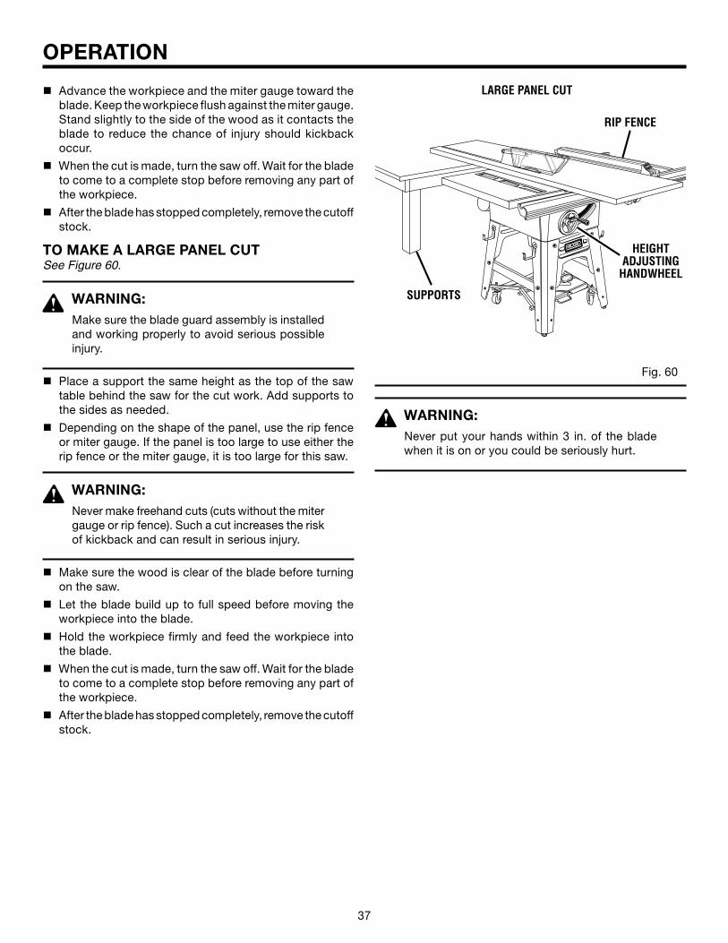
36 37
Æ
Æ
OPERATION
n Advance the workpiece and the miter gauge toward the blade. Keep the workpiece flush against the miter gauge. Stand slightly to the side of the wood as it contacts the blade to reduce the chance of injury should kickback occur.
n When the cut is made, turn the saw off. Wait for the blade to come to a complete stop before removing any part of the workpiece.
n After the blade has stopped completely, remove the cutoff stock.
TO MAKE A LARGE PANEL CUTSee Figure 60.
WARNING:Make sure the blade guard assembly is installed and working properly to avoid serious possible injury.
n Place a support the same height as the top of the saw table behind the saw for the cut work. Add supports to the sides as needed.
n Depending on the shape of the panel, use the rip fence or miter gauge. If the panel is too large to use either the rip fence or the miter gauge, it is too large for this saw.
WARNING:Never make freehand cuts (cuts without the miter gauge or rip fence). Such a cut increases the risk of kickback and can result in serious injury.
n Make sure the wood is clear of the blade before turning on the saw.
n Let the blade build up to full speed before moving the workpiece into the blade.
n Hold the workpiece firmly and feed the workpiece into the blade.
n When the cut is made, turn the saw off. Wait for the blade to come to a complete stop before removing any part of the workpiece.
n After the blade has stopped completely, remove the cutoff stock.
Fig. 60
LARGE PANEL CUT
SUPPORTS
HEIGHT ADJUSTING
HANDWHEEL
RIP FENCE
WARNING:Never put your hands within 3 in. of the blade when it is on or you could be seriously hurt.
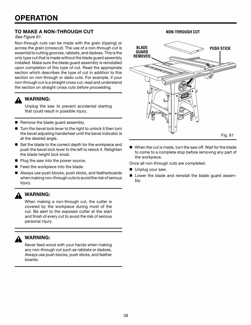
38 39
Æ
Æ
NON-THROUGH CUT
BLADE GUARD
REMOVED
PUSH STICK
Fig. 61
OPERATION
TO MAKE A NON-THROUGH CUTSee Figure 61.
Non-through cuts can be made with the grain (ripping) or across the grain (crosscut). The use of a non-through cut is essential to cutting grooves, rabbets, and dadoes. This is the only type cut that is made without the blade guard assembly installed. Make sure the blade guard assembly is reinstalled upon completion of this type of cut. Read the appropriate section which describes the type of cut in addition to this section on non-through or dado cuts. For example, if your non-through cut is a straight cross cut, read and understand the section on straight cross cuts before proceeding.
WARNING:Unplug the saw to prevent accidental starting that could result in possible injury.
n Remove the blade guard assembly.
n Turn the bevel lock lever to the right to unlock it then turn the bevel adjusting handwheel until the bevel indicator is at the desired angle.
n Set the blade to the correct depth for the workpiece and push the bevel lock lever to the left to relock it. Retighten the blade height lock knob.
n Plug the saw into the power source.
n Feed the workpiece into the blade.
n Always use push blocks, push sticks, and featherboards when making non-through cuts to avoid the risk of serious injury.
WARNING:When making a non-through cut, the cutter is covered by the workpiece during most of the cut. Be alert to the exposed cutter at the start and finish of every cut to avoid the risk of serious personal injury.
WARNING:Never feed wood with your hands when making any non-through cut such as rabbets or dadoes. Always use push blocks, push sticks, and feather boards.
n When the cut is made, turn the saw off. Wait for the blade to come to a complete stop before removing any part of the workpiece.
Once all non-through cuts are completed:
n Unplug your saw.
n Lower the blade and reinstall the blade guard assem-bly.
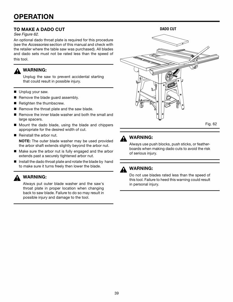
38 39
TO MAKE A DADO CUTSee Figure 62.
An optional dado throat plate is required for this procedure (see the Accessories section of this manual and check with the retailer where the table saw was purchased). All blades and dado sets must not be rated less than the speed of this tool.
WARNING:Unplug the saw to prevent accidental starting that could result in possible injury.
n Unplug your saw.
n Remove the blade guard assembly.
n Retighten the thumbscrew.
n Remove the throat plate and the saw blade.
n Remove the inner blade washer and both the small and large spacers.
n Mount the dado blade, using the blade and chippers appropriate for the desired width of cut.
n Reinstall the arbor nut.
NOTE: The outer blade washer may be used provided the arbor shaft extends slightly beyond the arbor nut.
n Make sure the arbor nut is fully engaged and the arbor extends past a securely tightened arbor nut.
n Install the dado throat plate and rotate the blade by hand to make sure it turns freely then lower the blade.
WARNING:Always put outer blade washer and the saw's throat plate in proper location when changing back to saw blade. Failure to do so may result in possible injury and damage to the tool.
OPERATION
WARNING:Always use push blocks, push sticks, or feather-boards when making dado cuts to avoid the risk of serious injury.
WARNING:Do not use blades rated less than the speed of this tool. Failure to heed this warning could result in personal injury.
DADO CUT
Fig. 62
®
®
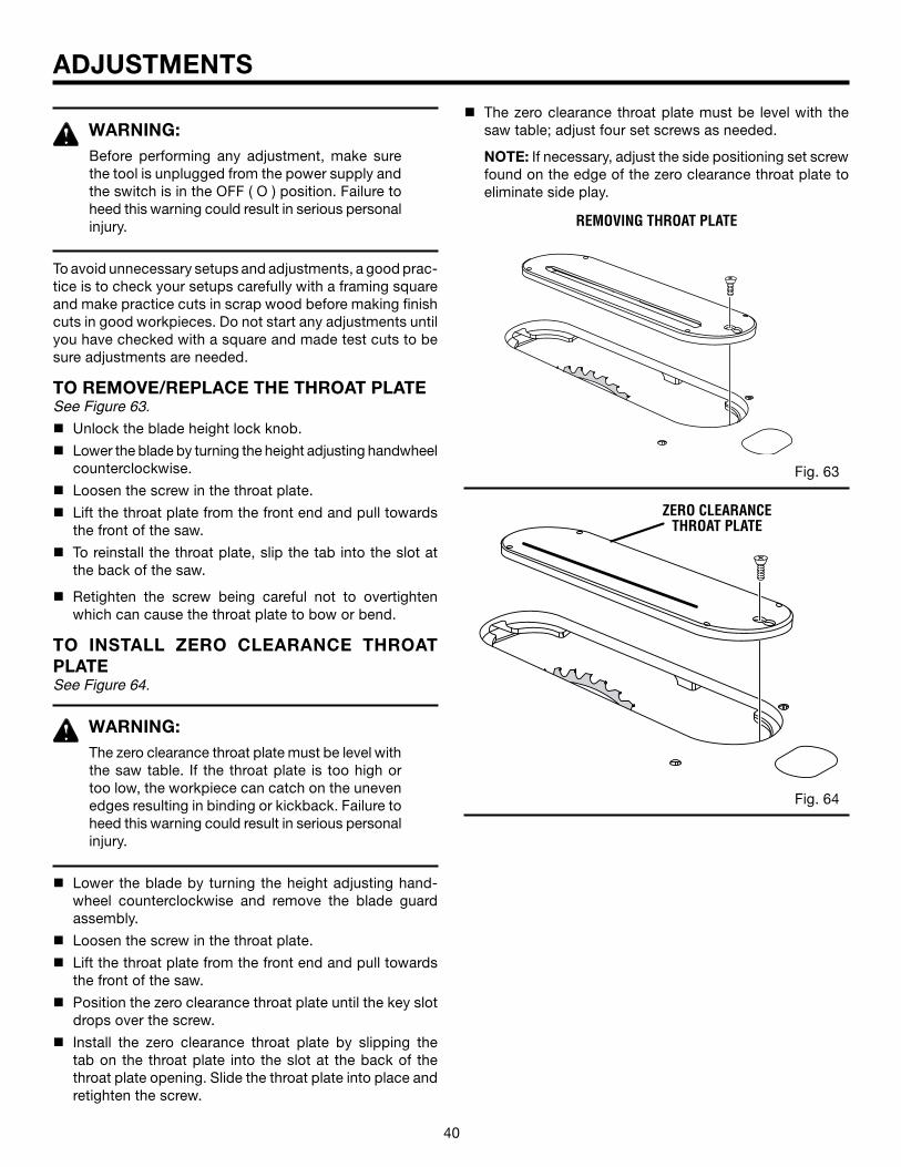
40 41
ADJUSTMENTS
WARNING:Before performing any adjustment, make sure the tool is unplugged from the power supply and the switch is in the OFF ( O ) position. Failure to heed this warning could result in serious personal injury.
To avoid unnecessary setups and adjustments, a good prac-tice is to check your setups carefully with a framing square and make practice cuts in scrap wood before making finish cuts in good workpieces. Do not start any adjustments until you have checked with a square and made test cuts to be sure adjustments are needed.
TO REMOVE/REPLACE THE THROAT PLATESee Figure 63.
n Unlock the blade height lock knob.
n Lower the blade by turning the height adjusting handwheel counterclockwise.
n Loosen the screw in the throat plate.
n Lift the throat plate from the front end and pull towards the front of the saw.
n To reinstall the throat plate, slip the tab into the slot at the back of the saw.
n Retighten the screw being careful not to overtighten which can cause the throat plate to bow or bend.
TO INSTALL ZERO CLEARANCE THROAT PLATESee Figure 64.
WARNING:The zero clearance throat plate must be level with the saw table. If the throat plate is too high or too low, the workpiece can catch on the uneven edges resulting in binding or kickback. Failure to heed this warning could result in serious personal injury.
n Lower the blade by turning the height adjusting hand-wheel counterclockwise and remove the blade guard assembly.
n Loosen the screw in the throat plate.
n Lift the throat plate from the front end and pull towards the front of the saw.
n Position the zero clearance throat plate until the key slot drops over the screw.
n Install the zero clearance throat plate by slipping the tab on the throat plate into the slot at the back of the throat plate opening. Slide the throat plate into place and retighten the screw.
Fig. 63
Fig. 64
REMOVING THROAT PLATE
ZERO CLEARANCE THROAT PLATE
n The zero clearance throat plate must be level with the saw table; adjust four set screws as needed.
NOTE: If necessary, adjust the side positioning set screw found on the edge of the zero clearance throat plate to eliminate side play.
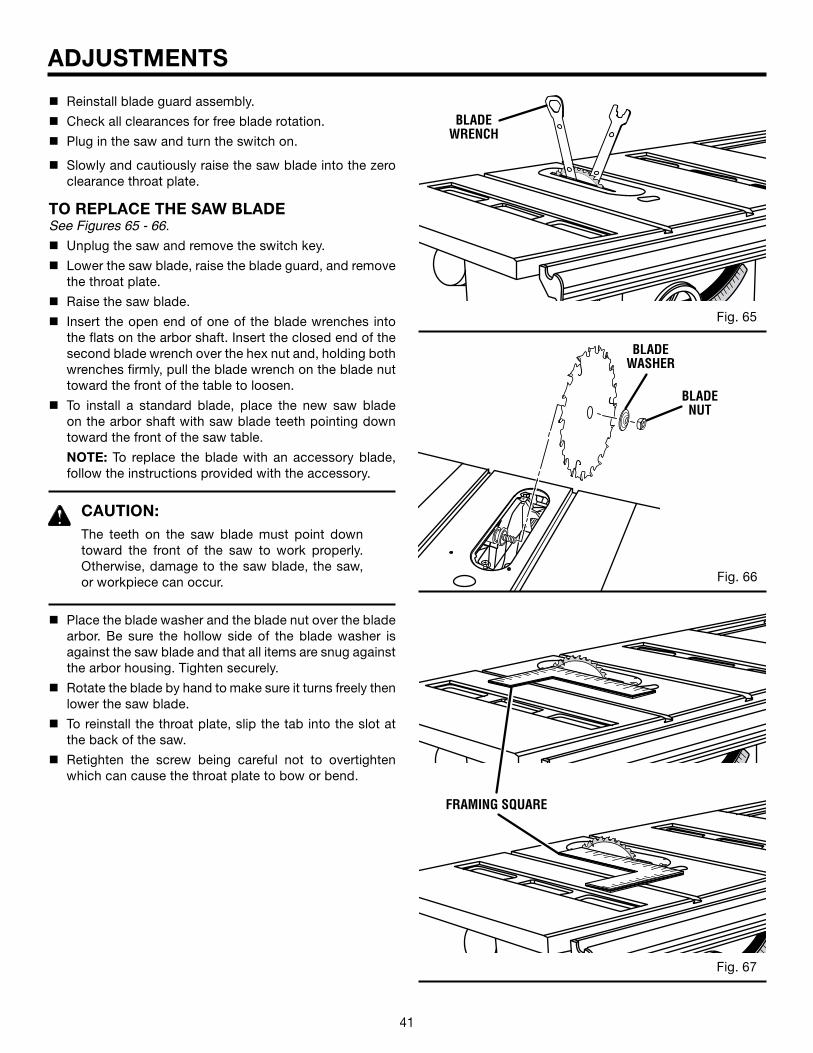
40 41
ADJUSTMENTS
n Reinstall blade guard assembly.
n Check all clearances for free blade rotation.
n Plug in the saw and turn the switch on.
n Slowly and cautiously raise the saw blade into the zero clearance throat plate.
TO REPLACE THE SAW BLADESee Figures 65 - 66.
n Unplug the saw and remove the switch key.
n Lower the saw blade, raise the blade guard, and remove the throat plate.
n Raise the saw blade.
n Insert the open end of one of the blade wrenches into the flats on the arbor shaft. Insert the closed end of the second blade wrench over the hex nut and, holding both wrenches firmly, pull the blade wrench on the blade nut toward the front of the table to loosen.
n To install a standard blade, place the new saw blade on the arbor shaft with saw blade teeth pointing down toward the front of the saw table.
NOTE: To replace the blade with an accessory blade, follow the instructions provided with the accessory.
CAUTION:The teeth on the saw blade must point down toward the front of the saw to work properly. Otherwise, damage to the saw blade, the saw, or workpiece can occur.
n Place the blade washer and the blade nut over the blade arbor. Be sure the hollow side of the blade washer is against the saw blade and that all items are snug against the arbor housing. Tighten securely.
n Rotate the blade by hand to make sure it turns freely then lower the saw blade.
n To reinstall the throat plate, slip the tab into the slot at the back of the saw.
n Retighten the screw being careful not to overtighten which can cause the throat plate to bow or bend.
Fig. 65
Fig. 66
Fig. 67
®
BLADE WRENCH
BLADE WASHER
BLADE NUT
®
®
FRAMING SQUARE
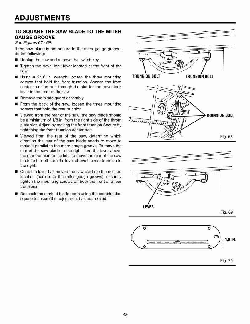
42 43
ADJUSTMENTS
TO SQUARE THE SAW BLADE TO THE MITER GAUGE GROOVESee Figures 67 - 69.
If the saw blade is not square to the miter gauge groove, do the following:
n Unplug the saw and remove the switch key.
n Tighten the bevel lock lever located at the front of the saw.
n Using a 9/16 in. wrench, loosen the three mounting screws that hold the front trunnion. Access the front center trunnion bolt through the slot for the bevel lock lever in the front of the saw.
n Remove the blade guard assembly.
n From the back of the saw, loosen the three mounting screws that hold the rear trunnion.
n Viewed from the rear of the saw, the saw blade should be a minimum of 1/8 in. from the right side of the throat plate slot. Adjust by moving the front trunnion.Secure by tightening the front trunnion center bolt.
n Viewed from the rear of the saw, determine which direction the rear of the saw blade needs to move to make it parallel to the miter gauge groove. To move the rear of the saw blade to the right, turn the lever above the rear trunnion to the left. To move the rear of the saw blade to the left, turn the lever above the rear trunnion to the right.
n Once the lever has moved the saw blade to the desired location (parallel to the miter gauge groove), securely tighten the mounting screws on both the front and rear trunnions.
n Recheck the marked blade tooth using the combination square to insure the adjustment has not moved.
Fig. 68
Fig. 69
Fig. 70
TRUNNION BOLT TRUNNION BOLT
TRUNNION BOLT
LEVER
1/8 IN.
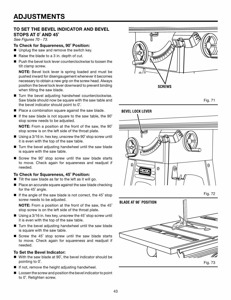
42 43
®
0 5 1015
2025
30
35
40
45
ADJUSTMENTS
TO SET THE BEVEL INDICATOR AND BEVEL STOPS AT 0˚ AND 45˚See Figures 70 - 73.
To Check for Squareness, 90˚ Position:n Unplug the saw and remove the switch key.
n Raise the blade to a 3 in. depth of cut.
n Push the bevel lock lever counterclockwise to loosen the tilt clamp screw.
NOTE: Bevel lock lever is spring loaded and must be pushed inward for disengaugement whenever it becomes necessary to obtain a new grip on the screw head. Always position the bevel lock lever downward to prevent binding when tilting the saw blade.
n Turn the bevel adjusting handwheel counterclockwise. Saw blade should now be square with the saw table and the bevel indicator should point to 0˚.
n Place a combination square against the saw blade.
n If the saw blade is not square to the saw table, the 90˚ stop screw needs to be adjusted.
NOTE: From a position at the front of the saw, the 90˚ stop screw is on the left side of the throat plate.
n Using a 3/16 in. hex key, unscrew the 90˚ stop screw until it is even with the top of the saw table.
n Turn the bevel adjusting handwheel until the saw blade is square with the saw table.
n Screw the 90˚ stop screw until the saw blade starts to move. Check again for squareness and readjust if needed.
To Check for Squareness, 45˚ Position:n Tilt the saw blade as far to the left as it will go.
n Place an accurate square against the saw blade checking for the 45˚ angle.
n If the angle of the saw blade is not correct, the 45˚ stop screw needs to be adjusted.
NOTE: From a position at the front of the saw, the 45˚ stop screw is on the left side of the throat plate.
n Using a 3/16 in. hex key, unscrew the 45˚ stop screw until it is even with the top of the saw table.
n Turn the bevel adjusting handwheel until the saw blade is square with the saw table.
n Screw the 45˚ stop screw until the saw blade starts to move. Check again for squareness and readjust if needed.
To Set the Bevel Indicator:n With the saw blade at 90˚, the bevel indicator should be
pointing to 0˚.
n If not, remove the height adjusting handwheel.
n Loosen the screw and position the bevel indicator to point to 0˚. Retighten screw.
Fig. 71
Fig. 72
Fig. 73
®
®
0 5 1015
2025
30
35
40
45
SCREWS
BLADE AT 90˚ POSITION
BEVEL LOCK LEVER
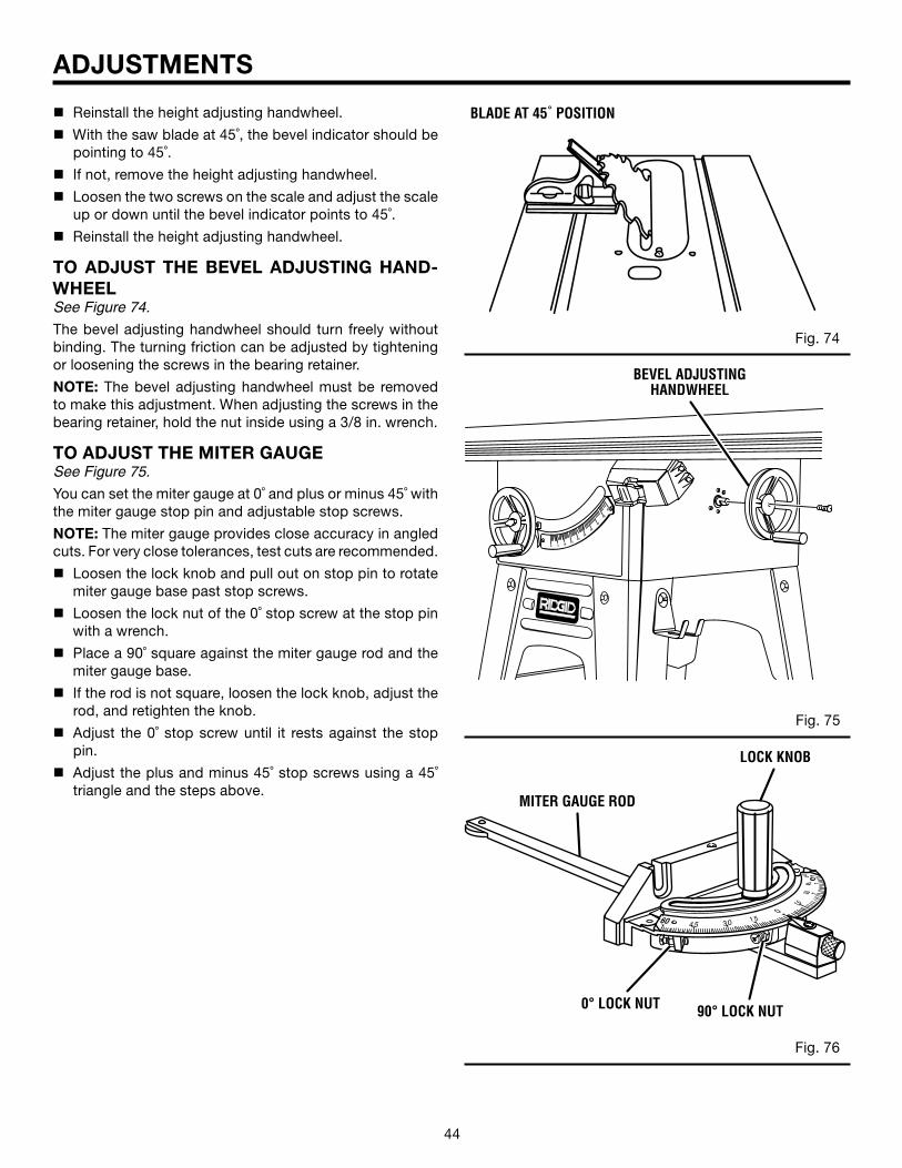
44 45
®
0 5 1015
2025
30
35
40
45
n Reinstall the height adjusting handwheel.
n With the saw blade at 45˚, the bevel indicator should be pointing to 45˚.
n If not, remove the height adjusting handwheel.
n Loosen the two screws on the scale and adjust the scale up or down until the bevel indicator points to 45˚.
n Reinstall the height adjusting handwheel.
TO ADJUST THE BEVEL ADJUSTING HAND- WHEELSee Figure 74.
The bevel adjusting handwheel should turn freely without binding. The turning friction can be adjusted by tightening or loosening the screws in the bearing retainer.
NOTE: The bevel adjusting handwheel must be removed to make this adjustment. When adjusting the screws in the bearing retainer, hold the nut inside using a 3/8 in. wrench.
TO ADJUST THE MITER GAUGESee Figure 75.
You can set the miter gauge at 0˚ and plus or minus 45˚ with the miter gauge stop pin and adjustable stop screws.
NOTE: The miter gauge provides close accuracy in angled cuts. For very close tolerances, test cuts are recommended.
n Loosen the lock knob and pull out on stop pin to rotate miter gauge base past stop screws.
n Loosen the lock nut of the 0˚ stop screw at the stop pin with a wrench.
n Place a 90˚ square against the miter gauge rod and the miter gauge base.
n If the rod is not square, loosen the lock knob, adjust the rod, and retighten the knob.
n Adjust the 0˚ stop screw until it rests against the stop pin.
n Adjust the plus and minus 45˚ stop screws using a 45˚ triangle and the steps above.
ADJUSTMENTS
Fig. 74
Fig. 75
Fig. 76
45 30 15
60
60
45
15
30
0
0° LOCK NUT
BLADE AT 45˚ POSITION
BEVEL ADJUSTING HANDWHEEL
90° LOCK NUT
MITER GAUGE ROD
LOCK KNOB
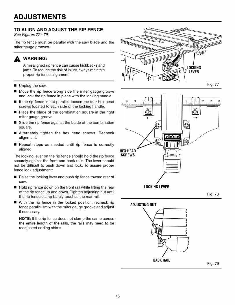
44 45
1918 25 26242322171615
®
ADJUSTMENTS
TO ALIGN AND ADJUST THE RIP FENCESee Figures 77 - 79.
The rip fence must be parallel with the saw blade and the miter gauge grooves.
WARNING:A misaligned rip fence can cause kickbacks and jams. To reduce the risk of injury, aways maintain proper rip fence alignment
n Unplug the saw.
n Move the rip fence along side the miter gauge groove and lock the rip fence in place with the locking handle.
n If the rip fence is not parallel, loosen the four hex head screws located to each side of the locking handle.
n Place the blade of the combination square in the right miter gauge groove.
n Slide the rip fence against the blade of the combination square.
n Alternately tighten the hex head screws. Recheck alignment.
n Repeat steps as needed until rip fence is correctly aligned.
The locking lever on the rip fence should hold the rip fence securely against the front and back rails. The lever should not be difficult to push down and lock. To assure proper fence lock adjustment:
n Raise the locking lever and push rip fence toward rear of saw.
n Hold rip fence down on the front rail while lifting the rear of the rip fence up and down. Tighten adjusting nut until the rip fence clamp barely touches the rear rail.
n With the rip fence in the locked position, recheck rip fence parallelism with the miter gauge groove and adjust if necessary.
NOTE: If the rip fence does not clamp the same across the entire length of the rails, the rails may need to be readjusted adding shims.
Fig. 77
Fig. 79
®
®
Fig. 78
LOCKING LEVER
HEX HEAD SCREWS
ADJUSTING NUT
BACK RAIL
LOCKING LEVER
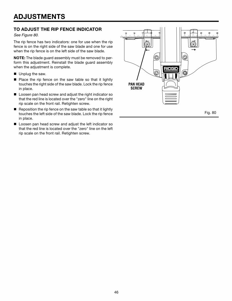
46
ADJUSTMENTS
TO ADJUST THE RIP FENCE INDICATORSee Figure 80.
The rip fence has two indicators: one for use when the rip fence is on the right side of the saw blade and one for use when the rip fence is on the left side of the saw blade.
NOTE: The blade guard assembly must be removed to per-form this adjustment. Reinstall the blade guard assembly when the adjustment is complete.
n Unplug the saw.
n Place the rip fence on the saw table so that it lightly touches the right side of the saw blade. Lock the rip fence in place.
n Loosen pan head screw and adjust the right indicator so that the red line is located over the "zero" line on the right rip scale on the front rail. Retighten screw.
n Reposition the rip fence on the saw table so that it lightly touches the left side of the saw blade. Lock the rip fence in place.
n Loosen pan head screw and adjust the left indicator so that the red line is located over the "zero" line on the left rip scale on the front rail. Retighten screw.
Fig. 80
1918 25 26242322171615
®
PAN HEAD SCREW
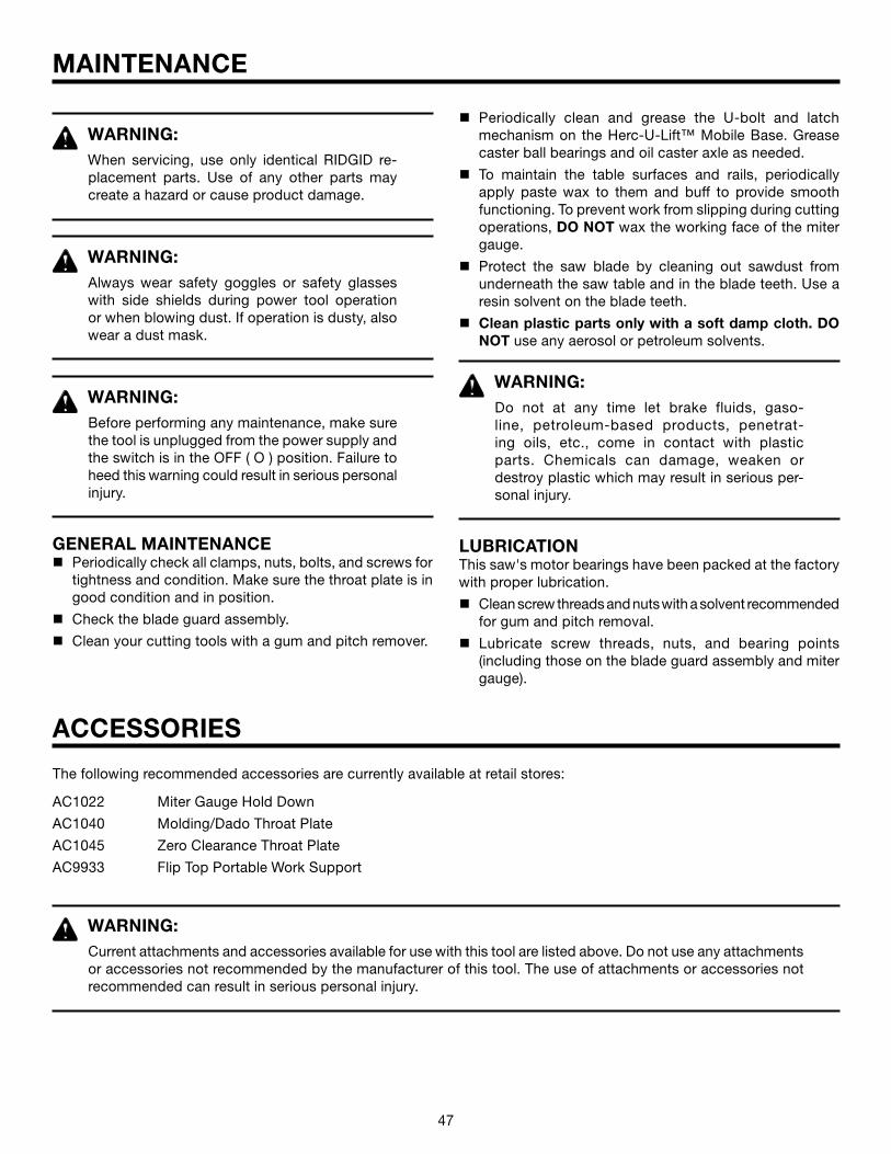
47
MAINTENANCE
The following recommended accessories are currently available at retail stores:
AC1022 Miter Gauge Hold Down
AC1040 Molding/Dado Throat Plate
AC1045 Zero Clearance Throat Plate
AC9933 Flip Top Portable Work Support
ACCESSORIES
WARNING:When servicing, use only identical RIDGID re-placement parts. Use of any other parts may create a hazard or cause product damage.
WARNING:Always wear safety goggles or safety glasses with side shields during power tool operation or when blowing dust. If operation is dusty, also wear a dust mask.
WARNING:Before performing any maintenance, make sure the tool is unplugged from the power supply and the switch is in the OFF ( O ) position. Failure to heed this warning could result in serious personal injury.
GENERAL MAINTENANCEn Periodically check all clamps, nuts, bolts, and screws for
tightness and condition. Make sure the throat plate is in good condition and in position.
n Check the blade guard assembly.
n Clean your cutting tools with a gum and pitch remover.
n Periodically clean and grease the U-bolt and latch mechanism on the Herc-U-Lift™ Mobile Base. Grease caster ball bearings and oil caster axle as needed.
n To maintain the table surfaces and rails, periodically apply paste wax to them and buff to provide smooth functioning. To prevent work from slipping during cutting operations, DO NOT wax the working face of the miter gauge.
n Protect the saw blade by cleaning out sawdust from underneath the saw table and in the blade teeth. Use a resin solvent on the blade teeth.
n Clean plastic parts only with a soft damp cloth. DO NOT use any aerosol or petroleum solvents.
WARNING:Do not at any time let brake fluids, gaso-line, petroleum-based products, penetrat-ing oils, etc., come in contact with plastic parts. Chemicals can damage, weaken ordestroy plastic which may result in serious per-sonal injury.
LUBRICATIONThis saw's motor bearings have been packed at the factory with proper lubrication.
n Clean screw threads and nuts with a solvent recommended for gum and pitch removal.
n Lubricate screw threads, nuts, and bearing points (including those on the blade guard assembly and miter gauge).
WARNING:Current attachments and accessories available for use with this tool are listed above. Do not use any attachments or accessories not recommended by the manufacturer of this tool. The use of attachments or accessories not recommended can result in serious personal injury.
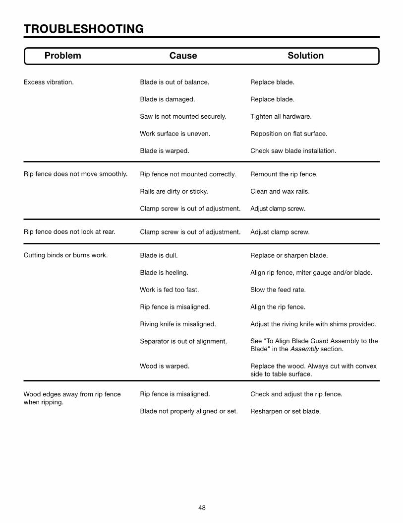
48 49
TROUBLESHOOTING
Problem Cause Solution
Excess vibration.
Rip fence does not move smoothly.
Rip fence does not lock at rear.
Cutting binds or burns work.
Wood edges away from rip fence when ripping.
Blade is out of balance.
Blade is damaged.
Saw is not mounted securely.
Work surface is uneven.
Blade is warped.
Rip fence not mounted correctly.
Rails are dirty or sticky.
Clamp screw is out of adjustment.
Clamp screw is out of adjustment.
Blade is dull.
Blade is heeling.
Work is fed too fast.
Rip fence is misaligned.
Riving knife is misaligned.
Separator is out of alignment.
Wood is warped.
Rip fence is misaligned.
Blade not properly aligned or set.
Replace blade.
Replace blade.
Tighten all hardware.
Reposition on flat surface.
Check saw blade installation.
Remount the rip fence.
Clean and wax rails.
Adjust clamp screw.
Adjust clamp screw.
Replace or sharpen blade.
Align rip fence, miter gauge and/or blade.
Slow the feed rate.
Align the rip fence.
Adjust the riving knife with shims provided.
See "To Align Blade Guard Assembly to the Blade" in the Assembly section.
Replace the wood. Always cut with convex side to table surface.
Check and adjust the rip fence.
Resharpen or set blade.

48 49
TROUBLESHOOTING
Problem Cause Solution
Saw does not make 90˚ or 45˚ cuts.
Height and Bevel Adjusting Hand-wheels are hard to turn.
Saw does not start.
Blade makes poor cuts.
Motor overheats.
Bevel stops not properly adjusted.
Miter gauge is misaligned (Miter Cuts).
Gears or Screw Post inside cabinet are clogged with sawdust.
Bearing retainer too tight.
Handwheel is locked.
Power cord not plugged in.
Circuit fuse is blown.
Circuit breaker is tripped.
Cord, switch, or motor is damaged.
Blade is dull or dirty.
Blade is wrong type for cut being made.
Blade is mounted backwards.
Work is fed too fast; motor over-loaded.
Blade not proper for rip cut, has fewer teeth.
See "To Set the Bevel Indicator and Bevel Stops at 0˚ and 45˚" in the Adjustments section.
See "To Adjust the Miter Gauge" in the Adjustments section.
Clean the gears or screw posts.
See "To Adjust the Bevel Adjusting Hand-wheel" in the Adjustments section.
Unlock the bevel adjusting handwheel by loosening the bevel lock lever. Unlock the height adjusting handwheel by turning the blade height lock knob counterclockwise.
Plug in power cord.
Replace circuit fuse.
Reset circuit breaker.
Have replaced by qualified service center.
Clean, sharpen, or replace blade.
Replace with correct type.
Remount blade.
Feed work slower into the blade.
Change blade; rip blade typically.Motor labors in rip cut.

50 51
NOTES
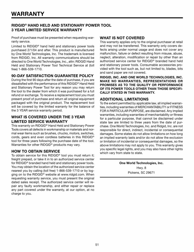
50 51
WARRANTY
Proof of purchase must be presented when requesting war-ranty service.
Limited to RIDGID® hand held and stationary power tools purchased 2/1/04 and after. This product is manufactured by One World Technologies, Inc. The trademark is licensed from RIDGID, Inc. All warranty communications should be directed to One World Technologies, Inc., attn: RIDGID Hand Held and Stationary Power Tool Technical Service at (toll free) 1-866-539-1710.
90-DAY SATISFACTION GUARANTEE POLICY During the first 90 days after the date of purchase, if you are dissatisfied with the performance of this RIDGID® Hand Held and Stationary Power Tool for any reason you may return the tool to the dealer from which it was purchased for a full refund or exchange. To receive a replacement tool you must present proof of purchase and return all original equipment packaged with the original product. The replacement tool will be covered by the limited warranty for the balance of the 3 YEAR service warranty period.
WHAT IS COVERED UNDER THE 3 YEAR LIMITED SERVICE WARRANTY This warranty on RIDGID® Hand Held and Stationary Power Tools covers all defects in workmanship or materials and nor-mal wear items such as brushes, chucks, motors, switches, cords, gears and even cordless batteries in this RIDGID®
tool for three years following the purchase date of the tool. Warranties for other RIDGID® products may vary.
HOW TO OBTAIN SERVICETo obtain service for this RIDGID® tool you must return it; freight prepaid, or take it in to an authorized service center for RIDGID® branded hand held and stationary power tools. You may obtain the location of the authorized service center nearest you by calling (toll free) 1-866-539-1710 or by log-ging on to the RIDGID® website at www.ridgid.com. When requesting warranty service, you must present the original dated sales receipt. The authorized service center will re-pair any faulty workmanship, and either repair or replace any part covered under the warranty, at our option, at no charge to you.
One World Technologies, Inc.
Hwy. 8
Pickens, SC 29671
RIDGID® HAND HELD AND STATIONARY POWER TOOL3 YEAR LIMITED SERVICE WARRANTY
WHAT IS NOT COVEREDThis warranty applies only to the original purchaser at retail and may not be transferred. This warranty only covers de-fects arising under normal usage and does not cover any malfunction, failure or defect resulting from misuse, abuse, neglect, alteration, modification or repair by other than an authorized service center for RIDGID® branded hand held and stationary power tools. Consumable accessories pro-vided with the tool such as, but not limited to, blades, bits and sand paper are not covered.
RIDGID, INC. AND ONE WORLD TECHNOLOGIES, INC. MAKE NO WARRANTIES, REPRESENTATIONS OR PROMISES AS TO THE QUALITY OR PERFORMANCE OF ITS POWER TOOLS OTHER THAN THOSE SPECIFI-CALLY STATED IN THIS WARRANTY.
ADDITIONAL LIMITATIONSTo the extent permitted by applicable law, all implied warran-ties, including warranties of MERCHANTABILITY or FITNESS FOR A PARTICULAR PURPOSE, are disclaimed. Any implied warranties, including warranties of merchantability or fitness for a particular purpose, that cannot be disclaimed under state law are limited to three years from the date of pur-chase. One World Technologies, Inc. and Ridgid, Inc. are not responsible for direct, indirect, incidental or consequential damages. Some states do not allow limitations on how long an implied warranty lasts and/or do not allow the exclusion or limitation of incidental or consequential damages, so the above limitations may not apply to you. This warranty gives you specific legal rights, and you may also have other rights which vary from state to state.

52
CUSTOMER SERVICE INFORMATIONFor parts or service, contact your nearest RIDGID authorized service center. Be sure to provide all relevant information when you call or visit. For the location of the authorized service center nearest you, please call 1-866-539-1710 or visit us online at www.ridgidwoodworking.com.
The model number of this tool is found on a plate attached to the motor housing. Please record the serial number in the space provided below. When ordering repair parts, always give the following information:
Model No.
Serial No.
TS3650
983000-402 11-05 (REV: 01)
OPERATOR'S MANUAL10 in. CAST IRON TABLE SAWTS3650
Related Documents