Instruction Manual PRINTED IN THE U.S.A 0606 PART NO. 197425-001 KEEP THIS MANUAL IN THE POCKET ON HEATER FOR FUTURE REFERENCE WHENEVER MAINTENANCE ADJUSTMENT OR SERVICE IS REQUIRED. POWER VENTED GAS MODELS W/HOT SURFACE IGNITION NOT FOR USE IN MANUFACTURED (MOBILE) HOMES ALL TECHNICAL AND WARRANTY QUESTIONS: SHOULD BE DIRECTED TO THE LOCAL DEALER FROM WHOM THE WATER HEATER WAS PURCHASED. IF YOU ARE UNSUCCESSFUL, PLEASE WRITE TO THE COMPANY LISTED ON THE RATING PLATE ON THE WATER HEATER. RESIDENTIAL GAS WATER HEATERS • For Your Safety • AN ODORANT IS ADDED TO THE GAS USED BY THIS WATER HEATER. www.statewaterheaters.com

Welcome message from author
This document is posted to help you gain knowledge. Please leave a comment to let me know what you think about it! Share it to your friends and learn new things together.
Transcript
1
Instruction Manual
PRINTED IN THE U.S.A 0606 PART NO. 197425-001
KEEP THIS MANUAL IN THE POCKET ON HEATER FOR FUTURE REFERENCEWHENEVER MAINTENANCE ADJUSTMENT OR SERVICE IS REQUIRED.
POWER VENTED GAS MODELS W/HOT SURFACE IGNITIONNOT FOR USE IN MANUFACTURED (MOBILE) HOMES
ALL TECHNICAL AND WARRANTY QUESTIONS: SHOULD BE DIRECTED TO THE LOCAL DEALER FROM WHOM THE WATER HEATER WASPURCHASED. IF YOU ARE UNSUCCESSFUL, PLEASE WRITE TO THE COMPANY LISTED ON THE RATING PLATE ON THE WATER HEATER.
RESIDENTIAL GAS WATER HEATERS
• For Your Safety •AN ODORANT IS ADDED TO THE GAS USED
BY THIS WATER HEATER.
www.statewaterheaters.com

2
SAFE INSTALLATION, USE AND SERVICEYour safety and the safety of others is extremely important in the installation, use and servicing of this water heater.
Many safety-related messages and instructions have been provided in this manual and on your own water heater to warn you andothers of a potential injury hazard. Read and obey all safety messages and instructions throughout this manual. It is veryimportant that the meaning of each safety message is understood by you and others who install, use or service this water heater.
All safety messages will generally tell you about the type of hazard, what can happen if you do not follow the safety message andhow to avoid the risk of injury.
IMPORTANT DEFINITIONS
• Qualified Installer: A qualified installer must have ability equivalent to a licensed tradesman in the fields of plumbing,air supply, venting and gas supply, including a thorough understanding of the requirements of the National Fuel GasCode as it relates to the installation of gas fired water heaters. The qualified installer must also be familiar with thedesign features of water heaters, and have a thorough understanding of this instruction manual.
• Service Agency: A service agency also must have ability equivalent to a licensed tradesman in the fields of plumbing,air supply, venting and gas supply, including a thorough understanding of the requirements of the National Fuel GasCode as it relates to the installation of gas fired water heaters. The service agency must also have a thoroughunderstanding of this instruction manual, and be able to perform repairs strictly in accordance with the service guidelinesprovided by the manufacturer.
• Gas Supplier: The Natural Gas or Propane Utility or service who supplies gas for utilization by the gas burningappliances within this application. The gas supplier typically has responsibility for the inspection and code approval ofgas piping up to and including the Natural Gas meter or Propane storage tank of a building. Many gas suppliers alsooffer service and inspection of appliances within the building.
3
GENERAL SAFETY
4
GENERAL SAFETY

5
Thank You for purchasing this water heater. Properly installed andmaintained, it should give you years of trouble free service.
Abbreviations Found In This Instruction Manual:• CSA - Canadian Standards Association• ANSI - American National Standards Institute• NFPA - National Fire Protection Association• ASME - American Society of Mechanical Engineers• GAMA - Gas Appliance Manufacturer’s Association• UL - Underwriters Laboratories Inc.
This gas-fired water heater is design certified by UnderwritersLaboratories Inc. under American National Standard/CSA Standardfor Gas Water Heaters ANSI Z21.10.3 • CSA 4.3 (current edition).
PREPARING FOR THE INSTALLATION
1. Read the “General Safety” section, page 3 and 4 of this manualfirst and then the entire manual carefully. If you don’t follow thesafety rules, the water heater will not operate properly. It couldcause DEATH, SERIOUS BODILY INJURY AND/OR PROPERTYDAMAGE.
This manual contains instructions for the installation, operation, andmaintenance of the gas-fired water heater. It also contains warningsthroughout the manual that you must read and be aware of. Allwarnings and all instructions are essential to the proper operation ofthe water heater and your safety. Since we cannot put everythingon the first few pages, READ THE ENTIRE MANUAL BEFOREATTEMPTING TO INSTALL OR OPERATE THE WATER HEATER.
2. The installation must conform with these instructions and thelocal code authority having jurisdiction. In the absence of localcodes, installations shall comply with the National Fuel Gas Code(ANSI Z223.1/NFPA 54) or the Natural Gas and PropaneInstallation Code (CAN/CSA B149.1) and the National ElectricalCode (NFPA 70), or the Canadian Electrical Code (C22.1). Thesepublications are available from The National Fire ProtectionAssociation, 1 Batterymarch Park, Quincy, MA 02269.
3. The water heater when installed must be grounded in accordancewith the local codes, or in the absence of local codes: the NationalElectrical Code (NFPA 70) or the Canadian Electrical Code (C22.1).
4. If after reading this manual you have any questions or do notunderstand any portion of the instructions, call the local gas utilityor the manufacturer whose name appears on the rating plate.
5. Carefully plan the place where you are going to put the waterheater. Correct combustion, vent action, and vent pipe installationare very important in preventing death from possible carbonmonoxide poisoning and fires, see Figures 1 and 2.
Examine the location to ensure the water heater complies withthe “Locating the New Water Heater” section in this manual.
6. For California installation this water heater must be braced,anchored, or strapped to avoid falling or moving during anearthquake. See instructions for correct installation procedures.Instructions may be obtained from California Office of the StateArchitect, 400 P Street, Sacramento, CA 95814.
7. Massachusetts Code requires this water heater to be installed inaccordance with Massachusetts 248-CMR 2.00: State PlumbingCode and 248-CMR 5.00.
8. Complies with SCAQMD rule #1146 and districts having equivalentNOx requirements.
INTRODUCTION
TABLE OF CONTENTSSAFE INSTALLATION, USE AND SERVICE ........................... 2GENERAL SAFETY ............................................................. 3-4TABLE OF CONTENTS ........................................................... 5INTRODUCTION ..................................................................... 5
Preparing for the Installation ............................................ 5TYPICAL INSTALLATION .................................................... 6-8LOCATING THE NEW WATER HEATER ........................... 9-11
Facts to Consider About Location .............................. 9-10Insulation Blankets ......................................................... 10Combustion Air and Ventilation for AppliancesLocated in Unconfined Spaces ....................................... 10Combustion Air and Ventilation for AppliancesLocated in Confined Spaces ..................................... 10-11
INSTALLING THE WATER HEATER ............................... 12-24Chemical Vapor Corrosion ............................................. 12Water Piping ............................................................. 12-13Temperature-Pressure Relief Valve ............................... 13Gas Piping ...................................................................... 14Sediment Traps .............................................................. 15Filling the Water Heater ................................................. 15Vent Pipe Assembly ....................................................... 15Venting ........................................................................... 15Vent Pipe Termination .................................................... 16Planning the Vent System .............................................. 17Condensate .............................................................. 17-18Blower Assembly Installation .......................................... 18Installation of Vent System ....................................... 18-20
Vent Attenuation Assembly Installation Instructions ....... 21-22Vent Pipe Preparation .............................................. 23-24
LIGHTING & OPERATING LABEL ........................................25TEMPERATURE REGULATION ............................................ 26FOR YOUR INFORMATION ..................................................27
Start Up ConditionsSmoke/Odor ...........................................................27Thermal Expansion ................................................. 27Strange Sounds ...................................................... 27
Operational Conditions ................................................... 27Smelly Water .......................................................... 27“Air” in Hot Water Faucets ...................................... 27High Temperature Shut Off System ........................ 27
PERIODIC MAINTENANCE ............................................ 28-30Venting System Inspection .............................................28Burner Operation and Inspection ...................................28Burner Cleaning ............................................................. 28Housekeeping .......................................................... 28-29Anode Rod Inspection .................................................... 29Temperature-Pressure Relief Valve Operation .............. 29Draining ..........................................................................29Service ........................................................................... 30
LEAKAGE CHECKPOINTS ................................................... 30REPAIR PARTS .....................................................................31TROUBLESHOOTING ..................................................... 32-34WARRANTY ..........................................................................35
6
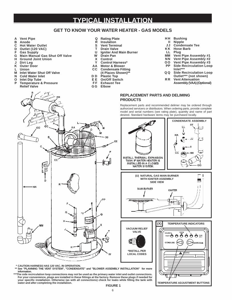
TYPICAL INSTALLATION
* CAUTION HARNESS HAS 120 VAC. IN OPERATION.** See "PLANNING THE VENT SYSTEM", "CONDENSATE" and "BLOWER ASSEMBLY INSTALLATION" for more
information.***The side recirculation loop connections may not be used as the primary water inlet and outlet connections.
For your convenience, plugs are installed in these fittings at the factory. Remove these plugs if needed foryour specific installation. Otherwise (as with all connections) check for leaks while filling the tank withwater and after completing the installation.
FIGURE 1
VACUUM RELIEFVALVE
*INSTALL PERLOCAL CODES
TEMPERATURE ADJUSTMENT BUTTONS
TEMPERATURE INDICATORS(X)
Q Rating PlateR InsulationS Vent TerminalT Drain ValveU Igniter And Main BurnerW Drain PanX ControlY Control Harness*
AA Motor & BlowerCC Condensate Fitting
(4 Places Shown)**D D Plastic TopE E On/Off SwitchF F Exhaust Tee
G G Elbow
GET TO KNOW YOUR WATER HEATER - GAS MODELS
A Vent PipeB AnodeC Hot Water OutletD Outlet (120 VAC)F Gas SupplyG Main Manual Gas Shut Off ValveH Ground Joint UnionJ Dirt LegK Outer DoorL UnionM Inlet Water Shut Off ValveN Cold Water InletO Inlet Dip TubeP Temperature & Pressure
Relief Valve
H H BushingII Nipple
J J Condensate TeeK K Hose BarbLL Plug
MM Vent Pipe Assembly #1NN Vent Pipe Assembly #2O O Vent Pipe Assembly #3PP Side Recirculation Loop
Inlet***Q Q Side Recirculation Loop
Outlet*** (not shown)R R Vent Attenuation
Assembly (VAA) (Optional)
CONDENSATE ASSEMBLY
(U) NATURAL GAS MAIN BURNERWITH IGNITER ASSEMBLY
SIDE VIEW
REPLACEMENT PARTS AND DELIMINGPRODUCTSReplacement parts and recommended delimer may be ordered throughauthorized servicers or distributors. When ordering parts, provide completemodel and serial numbers (see rating plate), quantity and name of partdesired. Standard hardware items may be purchased locally.
7
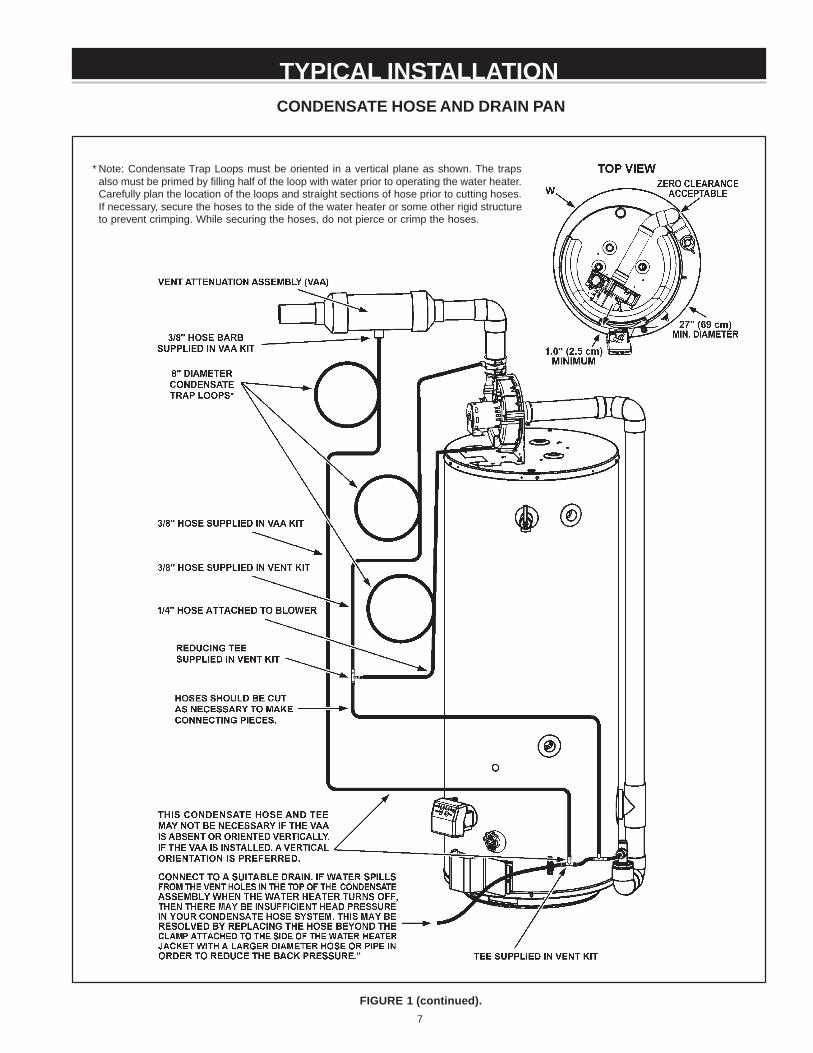
TYPICAL INSTALLATIONCONDENSATE HOSE AND DRAIN PAN
FIGURE 1 (continued).
* Note: Condensate Trap Loops must be oriented in a vertical plane as shown. The trapsalso must be primed by filling half of the loop with water prior to operating the water heater.Carefully plan the location of the loops and straight sections of hose prior to cutting hoses.If necessary, secure the hoses to the side of the water heater or some other rigid structureto prevent crimping. While securing the hoses, do not pierce or crimp the hoses.

8
TYPICAL INSTALLATION
FIGURE 2.
MIXING VALVE USAGE
This appliance has been design certified as complying with AmericanNational Standard/CSA Standard for water heaters and is consideredsuitable for:
Water (Potable) Heating and Space Heating: All models areconsidered suitable for water (potable) heating and space heating.
HOTTER WATER CAN SCALD:
Water heaters are intended to produce hot water. Water heated to atemperature which will satisfy space heating, clothes washing, dishwashing, and other sanitizing needs can scald and permanently injureyou upon contact. Some people are more likely to be permanentlyinjured by hot water than others. These include the elderly, children,the infirm, or physically/mentally handicapped. If anyone using hotwater in your home fits into one of these groups or if there is a localcode or state law requiring a certain temperature water at the hotwater tap, then you must take special precautions. In addition tousing the lowest possible temperature setting that satisfies your hotwater needs, a means such as a *Mixing Valve, shall be used at thehot water taps used by these people or at the water heater. Mixingvalves are available at plumbing supply or hardware stores. Consulta Qualified Installer or Service Agency. Follow mixing valvemanufacturer’s instructions for installation of the valves. Beforechanging the factory setting on the thermostat, read the “TemperatureRegulation” section in this manual, see Figure 26.
9
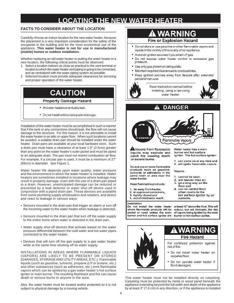
FACTS TO CONSIDER ABOUT THE LOCATION
Carefully choose an indoor location for the new water heater, becausethe placement is a very important consideration for the safety of theoccupants in the building and for the most economical use of theappliance. This water heater is not for use in manufactured(mobile) homes or outdoor installation.
Whether replacing an old water heater or putting the water heater in anew location, the following critical points must be observed:1. Select a location indoors as close as practical to the vent terminal or
location to which the water heater vent piping is going to be connected,and as centralized with the water piping system as possible.
2. Selected location must provide adequate clearances for servicingand proper operation of the water heater.
Installation of the water heater must be accomplished in such a mannerthat if the tank or any connections should leak, the flow will not causedamage to the structure. For this reason, it is not advisable to installthe water heater in an attic or upper floor. When such locations cannotbe avoided, a suitable drain pan should be installed under the waterheater. Drain pans are available at your local hardware store. Sucha drain pan must have a clearance of at least 1.0" (2.5cm) greaterthan any point on the water heater’s outer jacket and must be pipedto an adequate drain. The pan must not restrict combustion air flow.For example, if a circular pan is used, it must be a minimum of 27"(69cm) in diameter. See Figure 1.
Water heater life depends upon water quality, water pressureand the environment in which the water heater is installed. Waterheaters are sometimes installed in locations where leakage mayresult in property damage, even with the use of a drain pan pipedto a drain. However, unanticipated damage can be reduced orprevented by a leak detector or water shut-off device used inconjunction with a piped drain pan. These devices are availablefrom some plumbing supply wholesalers and retailers, and detectand react to leakage in various ways:
• Sensors mounted in the drain pan that trigger an alarm or turn offthe incoming water to the water heater when leakage is detected.
• Sensors mounted in the drain pan that turn off the water supplyto the entire home when water is detected in the drain pan.
• Water supply shut-off devices that activate based on the waterpressure differential between the cold water and hot water pipesconnected to the water heater.
• Devices that will turn off the gas supply to a gas water heaterwhile at the same time shutting off its water supply.
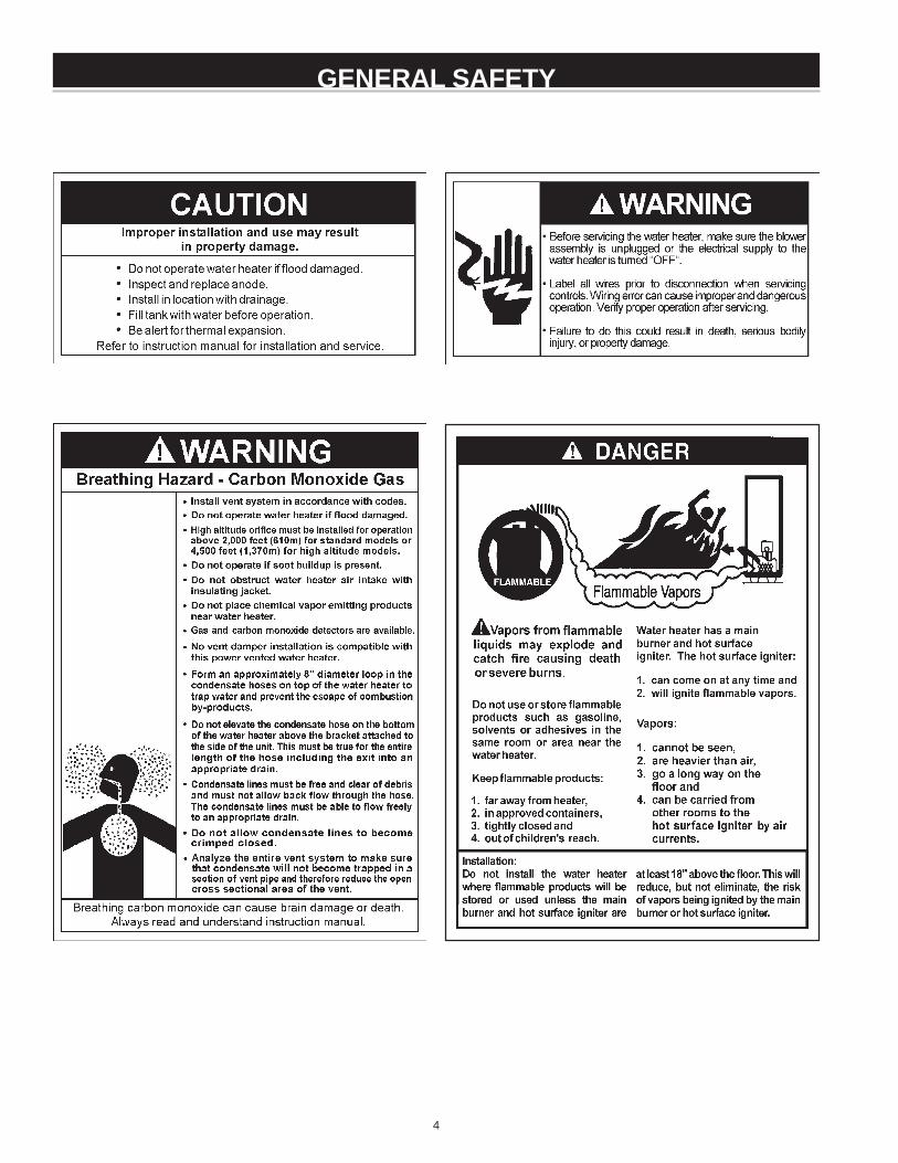
INSTALLATIONS IN AREAS WHERE FLAMMABLE LIQUIDS(VAPORS) ARE LIKELY TO BE PRESENT OR STORED(GARAGES, STORAGE AND UTILITY AREAS, ETC.): Flammableliquids (such as gasoline, solvents, propane (LP or butane, etc.)and other substances (such as adhesives, etc.) emit flammablevapors which can be ignited by a gas water heater’s hot surfaceigniter or main burner. The resulting flashback and fire can causedeath or serious burns to anyone in the area.
Also, the water heater must be located and/or protected so it is notsubject to physical damage by a moving vehicle.
LOCATING THE NEW WATER HEATER
This water heater must not be installed directly on carpeting.Carpeting must be protected by metal or wood panel beneath theappliance extending beyond the full width and depth of the applianceby at least 3" (7.6 cm) in any direction, or if the appliance is installed
10
in an alcove or closet, the entire floor must be covered by the panel.Failure to heed this warning may result in a fire hazard.
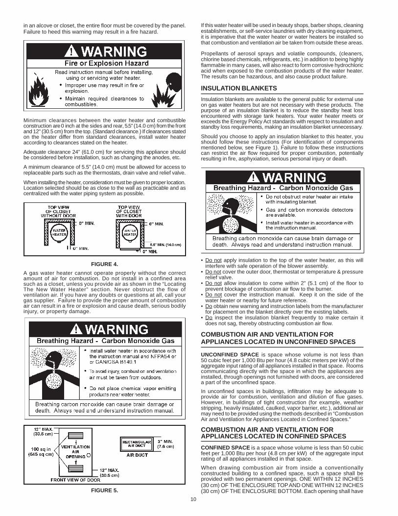
Minimum clearances between the water heater and combustibleconstruction are 0 inch at the sides and rear, 5.5" (14.0 cm) from the frontand 12" (30.5 cm) from the top. (Standard clearance.) If clearances statedon the heater differ from standard clearances, install water heateraccording to clearances stated on the heater.
Adequate clearance 24" (61.0 cm) for servicing this appliance shouldbe considered before installation, such as changing the anodes, etc.
A minimum clearance of 5.5" (14.0 cm) must be allowed for access toreplaceable parts such as the thermostats, drain valve and relief valve.
When installing the heater, consideration must be given to proper location.Location selected should be as close to the wall as practicable and ascentralized with the water piping system as possible.
FIGURE 4.A gas water heater cannot operate properly without the correctamount of air for combustion. Do not install in a confined areasuch as a closet, unless you provide air as shown in the “LocatingThe New Water Heater” section. Never obstruct the flow ofventilation air. If you have any doubts or questions at all, call yourgas supplier. Failure to provide the proper amount of combustionair can result in a fire or explosion and cause death, serious bodilyinjury, or property damage.
FIGURE 5.
If this water heater will be used in beauty shops, barber shops, cleaningestablishments, or self-service laundries with dry cleaning equipment,it is imperative that the water heater or water heaters be installed sothat combustion and ventilation air be taken from outside these areas.
Propellants of aerosol sprays and volatile compounds, (cleaners,chlorine based chemicals, refrigerants, etc.) in addition to being highlyflammable in many cases, will also react to form corrosive hydrochloricacid when exposed to the combustion products of the water heater.The results can be hazardous, and also cause product failure.
INSULATION BLANKETSInsulation blankets are available to the general public for external useon gas water heaters but are not necessary with these products. Thepurpose of an insulation blanket is to reduce the standby heat lossencountered with storage tank heaters. Your water heater meets orexceeds the Energy Policy Act standards with respect to insulation andstandby loss requirements, making an insulation blanket unnecessary.
Should you choose to apply an insulation blanket to this heater, youshould follow these instructions (For identification of componentsmentioned below, see Figure 1). Failure to follow these instructionscan restrict the air flow required for proper combustion, potentiallyresulting in fire, asphyxiation, serious personal injury or death.
• Do not apply insulation to the top of the water heater, as this willinterfere with safe operation of the blower assembly.
• Do not cover the outer door, thermostat or temperature & pressurerelief valve.
• Do not allow insulation to come within 2" (5.1 cm) of the floor toprevent blockage of combustion air flow to the burner.
• Do not cover the instruction manual. Keep it on the side of thewater heater or nearby for future reference.
• Do obtain new warning and instruction labels from the manufacturerfor placement on the blanket directly over the existing labels.
• Do inspect the insulation blanket frequently to make certain itdoes not sag, thereby obstructing combustion air flow.
COMBUSTION AIR AND VENTILATION FORAPPLIANCES LOCATED IN UNCONFINED SPACES
UNCONFINED SPACE is space whose volume is not less than50 cubic feet per 1,000 Btu per hour (4.8 cubic meters per kW) of theaggregate input rating of all appliances installed in that space. Roomscommunicating directly with the space in which the appliances areinstalled, through openings not furnished with doors, are considereda part of the unconfined space.In unconfined spaces in buildings, infiltration may be adequate toprovide air for combustion, ventilation and dilution of flue gases.However, in buildings of tight construction (for example, weatherstripping, heavily insulated, caulked, vapor barrier, etc.), additional airmay need to be provided using the methods described in “CombustionAir and Ventilation for Appliances Located in Confined Spaces.”
COMBUSTION AIR AND VENTILATION FORAPPLIANCES LOCATED IN CONFINED SPACESCONFINED SPACE is a space whose volume is less than 50 cubicfeet per 1,000 Btu per hour (4.8 cm per kW) of the aggregate inputrating of all appliances installed in that space.When drawing combustion air from inside a conventionallyconstructed building to a confined space, such a space shall beprovided with two permanent openings. ONE WITHIN 12 INCHES(30 cm) OF THE ENCLOSURE TOP AND ONE WITHIN 12 INCHES(30 cm) OF THE ENCLOSURE BOTTOM. Each opening shall have
11
a free area of one square inch per 1000 Btu/hr (22 cm2/kW) of thetotal input of all appliances in the enclosure, but not less than 100square inches (645 cm2).
If the confined space is within a building of tight construction, air forcombustion and ventilation must be obtained from outdoors. Whendirectly communicating with the outdoors or communicating throughvertical ducts, two permanent openings, located in the above manner,shall be provided. Each opening shall have a free area of not lessthan one square inch per 4000 Btu/hr (5.5 cm2/kW) of total input ofall appliances in the enclosure. If horizontal ducts are used, eachopening shall have a free area of not less than one square inch per2000 Btu/hr (11cm2/kW) of the total input of all appliances in the enclosure.
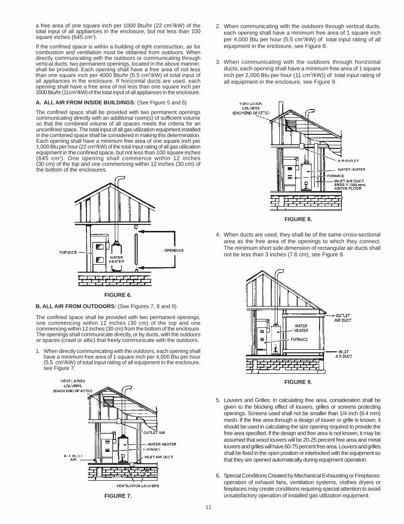
A. ALL AIR FROM INSIDE BUILDINGS: (See Figure 5 and 6)
The confined space shall be provided with two permanent openingscommunicating directly with an additional room(s) of sufficient volumeso that the combined volume of all spaces meets the criteria for anunconfined space. The total input of all gas utilization equipment installedin the combined space shall be considered in making this determination.Each opening shall have a minimum free area of one square inch per1,000 Btu per hour (22 cm2/kW) of the total input rating of all gas utilizationequipment in the confined space, but not less than 100 square inches(645 cm2). One opening shall commence within 12 inches(30 cm) of the top and one commencing within 12 inches (30 cm) ofthe bottom of the enclosures.
FIGURE 6.
B. ALL AIR FROM OUTDOORS: (See Figures 7, 8 and 9)
The confined space shall be provided with two permanent openings,one commencing within 12 inches (30 cm) of the top and onecommencing within 12 inches (30 cm) from the bottom of the enclosure.The openings shall communicate directly, or by ducts, with the outdoorsor spaces (crawl or attic) that freely communicate with the outdoors.
1. When directly communicating with the outdoors, each opening shallhave a minimum free area of 1 square inch per 4,000 Btu per hour(5.5 cm2/kW) of total input rating of all equipment in the enclosure,see Figure 7.
FIGURE 7.
2. When communicating with the outdoors through vertical ducts,each opening shall have a minimum free area of 1 square inchper 4,000 Btu per hour (5.5 cm2/kW) of total input rating of allequipment in the enclosure, see Figure 8.
3. When communicating with the outdoors through horizontalducts, each opening shall have a minimum free area of 1 squareinch per 2,000 Btu per hour (11 cm2/kW)) of total input rating ofall equipment in the enclosure, see Figure 9.
FIGURE 8.
4. When ducts are used, they shall be of the same cross-sectionalarea as the free area of the openings to which they connect.The minimum short side dimension of rectangular air ducts shallnot be less than 3 inches (7.6 cm), see Figure 9.
FIGURE 9.
5. Louvers and Grilles: In calculating free area, consideration shall begiven to the blocking effect of louvers, grilles or screens protectingopenings. Screens used shall not be smaller than 1/4 inch (6.4 mm)mesh. If the free area through a design of louver or grille is known, itshould be used in calculating the size opening required to provide thefree area specified. If the design and free area is not known, it may beassumed that wood louvers will be 20-25 percent free area and metallouvers and grilles will have 60-75 percent free area. Louvers and grillesshall be fixed in the open position or interlocked with the equipment sothat they are opened automatically during equipment operation.
6. Special Conditions Created by Mechanical Exhausting or Fireplaces:operation of exhaust fans, ventilation systems, clothes dryers orfireplaces may create conditions requiring special attention to avoidunsatisfactory operation of installed gas utilization equipment.
12
Water supply systems may, because of such events as high line pressure,frequent cut-offs, the effects of water hammer among others, haveinstalled devices such as pressure reducing valves, check valves, backflow preventers, etc. to control these types of problems. When thesedevices are not equipped with an internal by-pass, and no other measuresare taken, the devices cause the water system to be closed. As water isheated, it expands (thermal expansion) and closed systems do not allowfor the expansion of heated water.
The water within the water heater tank expands as it is heated and increasesthe pressure of the water system. If the relieving point of the water heater’stemperature-pressure relief valve is reached, the valve will relieve theexcess pressure. The temperature-pressure relief valve is not intendedfor the constant relief of thermal expansion. This is an unacceptablecondition and must be corrected.
It is recommended that any devices installed which could create a closedsystem have a by-pass and/or the system have an expansion tank torelieve the pressure built by thermal expansion in the water system.Expansion tanks are available for ordering through a local plumbingcontractor. Contact the local water supplier and/or a service agency forassistance in controlling these situations.
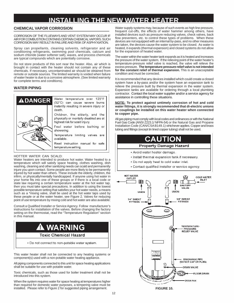
NOTE: To protect against untimely corrosion of hot and coldwater fittings, it is strongly recommended that di-electric unionsor couplings be installed on this water heater when connectedto copper pipe.All gas piping must comply with local codes and ordinances or with the NationalFuel Gas Code (ANSI Z223.1/ NFPA-54) or the Natural Gas and PropaneInstallation Code (CAN/CSA B149.1) whichever applies. Copper and brasstubing and fittings (except tin lined copper tubing) shall not be used.
FIGURE 10.
CHEMICAL VAPOR CORROSION
CORROSION OF THE FLUEWAYS AND VENT SYSTEM MAY OCCUR IFAIR FOR COMBUSTION CONTAINS CERTAIN CHEMICAL VAPORS. SUCHCORROSION MAY RESULT IN FAILURE AND RISK OF ASPHYXIATION.
Spray can propellants, cleaning solvents, refrigerator and airconditioning refrigerants, swimming pool chemicals, calcium andsodium chloride (water softener salt), waxes, and process chemicalsare typical compounds which are potentially corrosive.
Do not store products of this sort near the heater. Also, air which isbrought in contact with the heater should not contain any of thesechemicals. If necessary, uncontaminated air should be obtained fromremote or outside sources. The limited warranty is voided when failureof water heater is due to a corrosive atmosphere. (See limited warrantyfor complete terms and conditions).
WATER PIPING
HOTTER WATER CAN SCALD:Water heaters are intended to produce hot water. Water heated to atemperature which will satisfy space heating, clothes washing, dishwashing, cleaning and other sanitizing needs can scald and permanentlyinjure you upon contact. Some people are more likely to be permanentlyinjured by hot water than others. These include the elderly, children, theinfirm, or physically/mentally handicapped. If anyone using hot water inyour home fits into one of these groups or if there is a local code orstate law requiring a certain temperature water at the hot water tap,then you must take special precautions. In addition to using the lowestpossible temperature setting that satisfies your hot water needs, a meanssuch as a *mixing valve, shall be used at the hot water taps used bythese people or at the water heater, see Figure 2. Valves for reducingpoint of use temperature by mixing cold and hot water are also available:
Consult a Qualified Installer or Service Agency. Follow manufacturer’sinstructions for installation of the valves. Before changing the factorysetting on the thermostat, read the “Temperature Regulation” sectionin this manual.
This water heater shall not be connected to any heating systems orcomponent(s) used with a non-potable water heating appliance.
All piping components connected to this unit for space heating applicationsshall be suitable for use with potable water.
Toxic chemicals, such as those used for boiler treatment shall not beintroduced into this system.
When the system requires water for space heating at temperatures higherthan required for domestic water purposes, a tempering valve must beinstalled. Please refer to Figure 2 for suggested piping arrangement.
INSTALLING THE NEW WATER HEATER
13
Figure 10 shows the typical attachment of the water piping to thewater heater. The water heater is equipped with 3/4 inch NPTwater connections.
NOTE: If using copper tubing, solder tubing to an adapter beforeattaching the adapter to the water heater connections. Do notsolder the water lines directly to the water heater connections.It will harm the dip tube and damage the tank.
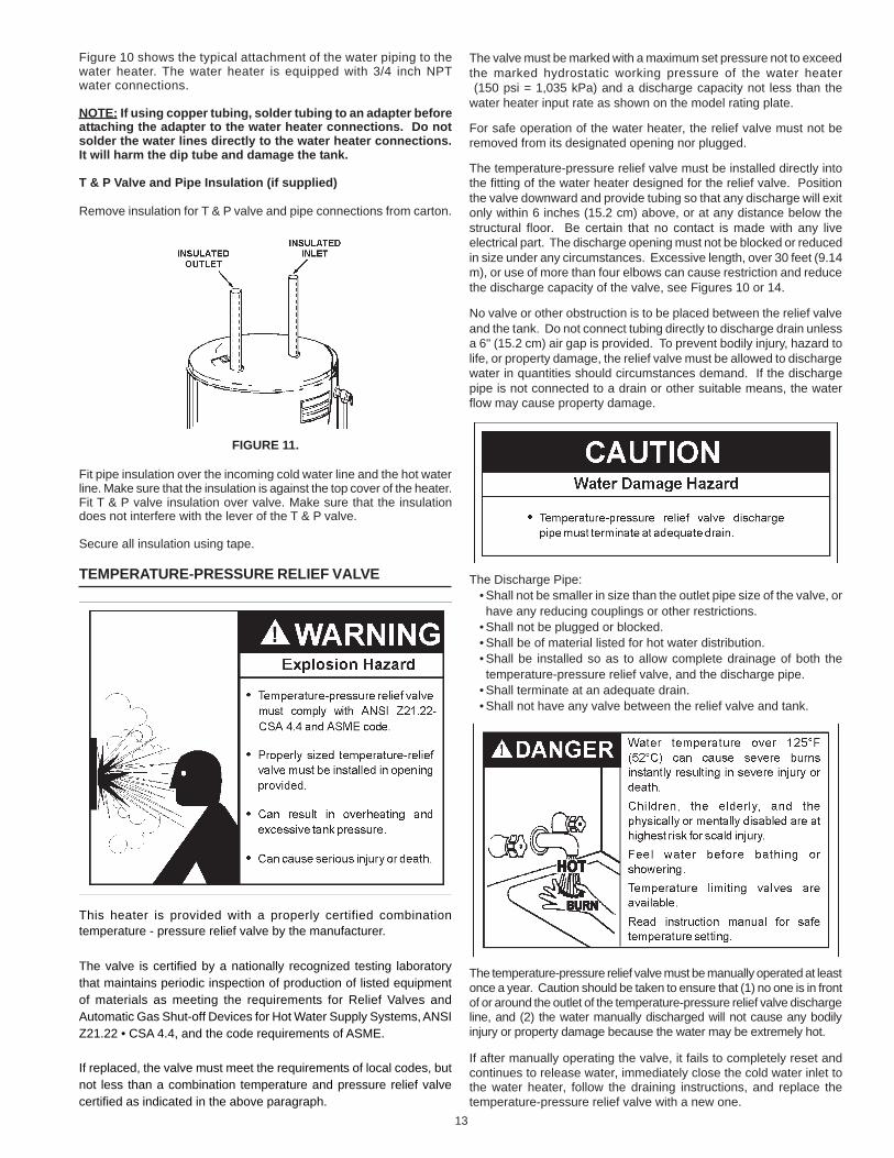
T & P Valve and Pipe Insulation (if supplied)
Remove insulation for T & P valve and pipe connections from carton.
FIGURE 11.
Fit pipe insulation over the incoming cold water line and the hot waterline. Make sure that the insulation is against the top cover of the heater.Fit T & P valve insulation over valve. Make sure that the insulationdoes not interfere with the lever of the T & P valve.
Secure all insulation using tape.
TEMPERATURE-PRESSURE RELIEF VALVE
This heater is provided with a properly certified combinationtemperature - pressure relief valve by the manufacturer.
The valve is certified by a nationally recognized testing laboratorythat maintains periodic inspection of production of listed equipmentof materials as meeting the requirements for Relief Valves andAutomatic Gas Shut-off Devices for Hot Water Supply Systems, ANSIZ21.22 • CSA 4.4, and the code requirements of ASME.
If replaced, the valve must meet the requirements of local codes, butnot less than a combination temperature and pressure relief valvecertified as indicated in the above paragraph.
The valve must be marked with a maximum set pressure not to exceedthe marked hydrostatic working pressure of the water heater (150 psi = 1,035 kPa) and a discharge capacity not less than thewater heater input rate as shown on the model rating plate.
For safe operation of the water heater, the relief valve must not beremoved from its designated opening nor plugged.
The temperature-pressure relief valve must be installed directly intothe fitting of the water heater designed for the relief valve. Positionthe valve downward and provide tubing so that any discharge will exitonly within 6 inches (15.2 cm) above, or at any distance below thestructural floor. Be certain that no contact is made with any liveelectrical part. The discharge opening must not be blocked or reducedin size under any circumstances. Excessive length, over 30 feet (9.14m), or use of more than four elbows can cause restriction and reducethe discharge capacity of the valve, see Figures 10 or 14.
No valve or other obstruction is to be placed between the relief valveand the tank. Do not connect tubing directly to discharge drain unlessa 6" (15.2 cm) air gap is provided. To prevent bodily injury, hazard tolife, or property damage, the relief valve must be allowed to dischargewater in quantities should circumstances demand. If the dischargepipe is not connected to a drain or other suitable means, the waterflow may cause property damage.
The Discharge Pipe:• Shall not be smaller in size than the outlet pipe size of the valve, orhave any reducing couplings or other restrictions.
• Shall not be plugged or blocked.• Shall be of material listed for hot water distribution.• Shall be installed so as to allow complete drainage of both thetemperature-pressure relief valve, and the discharge pipe.
• Shall terminate at an adequate drain.• Shall not have any valve between the relief valve and tank.
The temperature-pressure relief valve must be manually operated at leastonce a year. Caution should be taken to ensure that (1) no one is in frontof or around the outlet of the temperature-pressure relief valve dischargeline, and (2) the water manually discharged will not cause any bodilyinjury or property damage because the water may be extremely hot.
If after manually operating the valve, it fails to completely reset andcontinues to release water, immediately close the cold water inlet tothe water heater, follow the draining instructions, and replace thetemperature-pressure relief valve with a new one.
14
GAS PIPING
Make sure the gas supplied is the same type listed on the model ratingplate. The inlet gas pressure must not exceed 14 inch water column (3.5kPa) for natural and propane gas (L.P.). The minimum inlet gas pressureshown on the rating plate is that which will permit firing at rated input.
All gas piping must comply with local codes and ordinances or with theNational Fuel Gas Code (ANSI Z223.1/ NFPA-54) or the Natural Gas andPropane Installation Code (CAN/CSA B149.1) whichever applies. Copperand brass tubing and fittings (except tin lined copper tubing) shall not be used.
If the gas control valve is subjected to pressures exceeding 1/2 psi(3.5 kPa), the damage to the gas control valve could result in a fireor explosion from leaking gas.
If the main gas line Shut-off serving all gas appliances is used, alsoturn “off” the gas at each appliance. Leave all gas appliances shut“off” until the water heater installation is complete.
A gas line of sufficient size must be run to the water heater. Consultthe current edition of National Fuel Gas Code (ANSI Z223.1/NFPA54) or the Natural Gas and Propane Installation Code (CAN/CSAB149.1) and your gas supplier concerning pipe size.
There must be:• A readily accessible manual shut off valve in the gas supply line
serving the water heater, and• A drip leg (sediment trap) ahead of the gas control valve to help
prevent dirt and foreign materials from entering the gas control valve.• A flexible gas connector or a ground joint union between the shut
off valve and control valve to permit servicing of the unit.
Be sure to check all the gas piping for leaks before lighting the waterheater. Use a soapy water solution, not a match or open flame.Rinse off soapy solution and wipe dry.
When installed at elevations above 2,000 feet (610 meters) forstandard models or 4,500 feet (1,370m) for high altitude models, inputrating should be reduced at the rate of 4 percent for each 1,000 feet(305 meters) above sea level which requires replacement of the burnerorifice in accordance with National Fuel Gas Code (ANSI Z223.1/NFPA 54) or the Natural Gas and Propane Installation Code (CAN/CSA B149.1). Contact your local gas supplier for further information.
Failure to replace the standard orifice with a high altitude orifice wheninstalled could result in improper and inefficient operation of theappliance, producing carbon monoxide gas in excess of safe limits,which could result in serious injury or death. Contact your gas supplierfor any specific changes which may be required in your area.
Use pipe joint compound or teflon tape marked as being resistant tothe action of petroleum [Propane (L.P.)] gases.
The appliance and its gas connection must be leak tested beforeplacing the appliance in operation.
The appliance and its individual Shut-off valve shall be disconnectedfrom the gas supply piping system during any pressure testing ofthat system at test pressures in excess of 1/2 pound per squareinch (3.5 kPa). It shall be isolated from the gas supply piping systemby closing its individual manual Shut-off valve during any pressuretesting of the gas supply piping system at test pressures equal to orless than 1/2 pound per square inch (3.5 kPa).
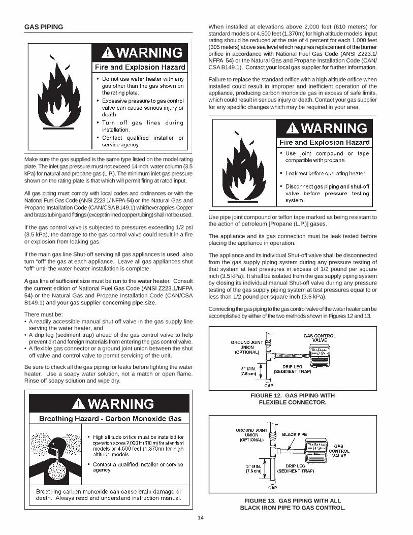
Connecting the gas piping to the gas control valve of the water heater can beaccomplished by either of the two methods shown in Figures 12 and 13.
FIGURE 12. GAS PIPING WITHFLEXIBLE CONNECTOR.
FIGURE 13. GAS PIPING WITH ALLBLACK IRON PIPE TO GAS CONTROL.
15
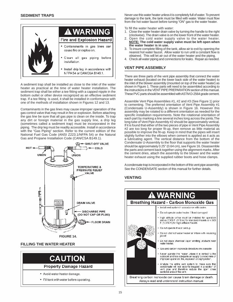
SEDIMENT TRAPS
A sediment trap shall be installed as close to the inlet of the waterheater as practical at the time of water heater installation. Thesediment trap shall be either a tee fitting with a capped nipple in thebottom outlet or other device recognized as an effective sedimenttrap. If a tee fitting is used, it shall be installed in conformance withone of the methods of installation shown in Figures 12 and 13.
Contaminants in the gas lines may cause improper operation of thegas control valve that may result in fire or explosion. Before attachingthe gas line be sure that all gas pipe is clean on the inside. To trapany dirt or foreign material in the gas supply line, a drip leg(sometimes called a sediment trap) must be incorporated in thepiping. The drip leg must be readily accessible. Install in accordancewith the “Gas Piping” section. Refer to the current edition of theNational Fuel Gas Code (ANSI Z223.1/NFPA 54) or the NaturalGas and Propane Installation Code (CAN/CSA B149.1).
FIGURE 14.
FILLING THE WATER HEATER
Never use this water heater unless it is completely full of water. To preventdamage to the tank, the tank must be filled with water. Water must flowfrom the hot water faucet before turning “ON” gas to the water heater.
To fill the water heater with water:1. Close the water heater drain valve by turning the handle to the right
(clockwise). The drain valve is on the lower front of the water heater.2. Open the cold water supply valve to the water heater.
NOTE: The cold water supply valve must be left open whenthe water heater is in use.
3. To insure complete filling of the tank, allow air to exit by opening thenearest hot water faucet. Allow water to run until a constant flow isobtained. This will let air out of the water heater and the piping.
4. Check all water piping and connections for leaks. Repair as needed.
VENT PIPE ASSEMBLY
There are three parts of the vent pipe assembly that connect the waterheater exhaust (located on the lower back side of the water heater) tothe inlet of the blower assembly (mounted on top of the water heater) asshown in Figure 1. These parts will need to be assembled according tothe instructions in the VENT PIPE PREPARATION section of this manual.These PVC parts should be assembled with ASTM D-2564 grade cement.
Assemble Vent Pipe Assemblies #1, #2 and #3 (See Figure 1) priorto cementing. The preferred orientation of Vent Pipe Assembly #1(Condensate U-Assembly) is shown in Figure 16. However thisassembly may be rotated to a different orientation as needed for thespecific installation requirements. Note the rotational orientation ofeach part by marking a line several inches long across the joints.Thelong tube of Vent Pipe Assembly #2 should be approximately vertical.If it is found that either of the two pieces of pipe in Vent Pipe Assembly#2 are too long for proper fit-up, then remove as little material aspossible to improve the fit-up. Keep in mind that the pipes will insertslightly further into the elbows when cement is applied as it acts asa lubricating agent. The vertical distance from the bottom of theCondensate U-Assembly to the floor that supports the water heatershould be approximately 0.25" (0.64 cm), see Figure 16. Disassemblethe parts and cement back together using the alignment marks. Afterthe cement dries, attach the assembly to the blower and the waterheater exhaust using the supplied rubber boots and hose clamps.
A condensate trap is incorporated in the bottom of this vent pipe assembly.See the CONDENSATE section of this manual for further details.
VENTING
16
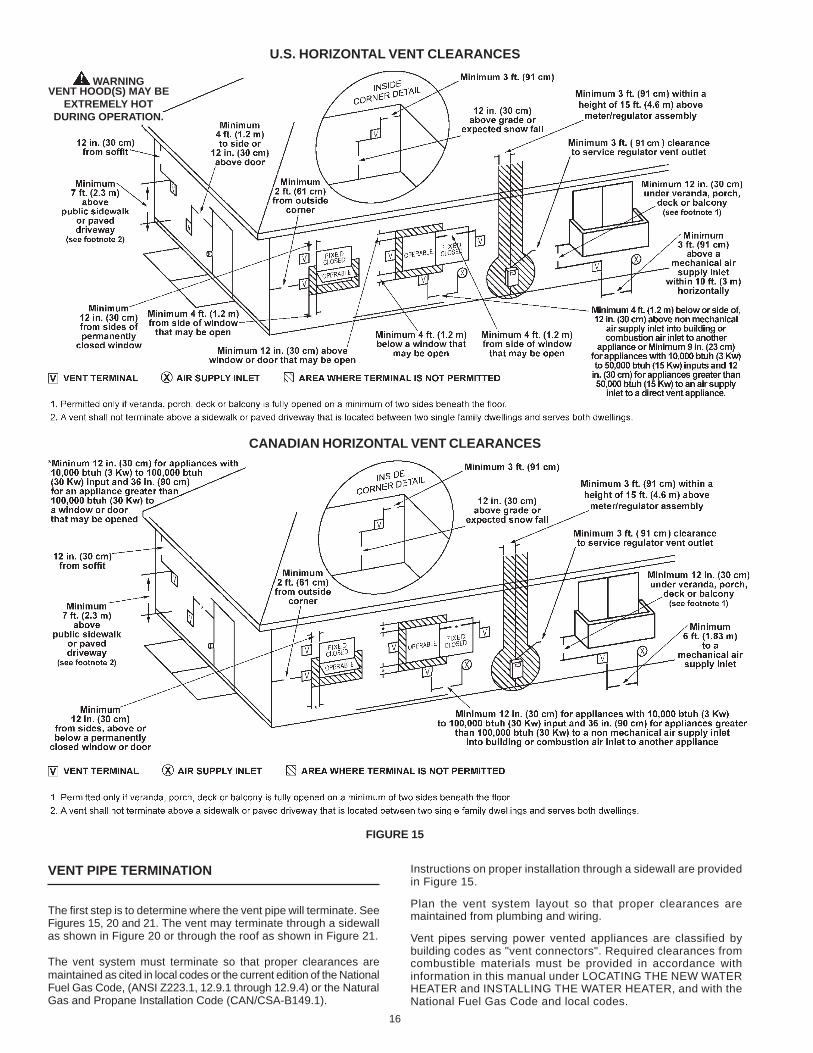
VENT PIPE TERMINATION
The first step is to determine where the vent pipe will terminate. SeeFigures 15, 20 and 21. The vent may terminate through a sidewallas shown in Figure 20 or through the roof as shown in Figure 21.
The vent system must terminate so that proper clearances aremaintained as cited in local codes or the current edition of the NationalFuel Gas Code, (ANSI Z223.1, 12.9.1 through 12.9.4) or the NaturalGas and Propane Installation Code (CAN/CSA-B149.1).
Instructions on proper installation through a sidewall are providedin Figure 15.
Plan the vent system layout so that proper clearances aremaintained from plumbing and wiring.
Vent pipes serving power vented appliances are classified bybuilding codes as "vent connectors". Required clearances fromcombustible materials must be provided in accordance withinformation in this manual under LOCATING THE NEW WATERHEATER and INSTALLING THE WATER HEATER, and with theNational Fuel Gas Code and local codes.
FIGURE 15
U.S. HORIZONTAL VENT CLEARANCES
CANADIAN HORIZONTAL VENT CLEARANCES
WARNINGVENT HOOD(S) MAY BE
EXTREMELY HOTDURING OPERATION.

17
PLANNING THE VENT SYSTEM
Plan the route of the vent system from the discharge of the blowerto the planned location of the vent terminal.
1. Layout total vent system to use a minimum of vent pipe and elbows.
2. This water heater is capable of venting flue gases equivalent to25' (7.6 m) of 2" pipe, 65' (19.8 m) of 3" pipe, or 128' (39.0 m) of4" pipe as listed in Table 1.
TABLE 1
Number of 2" Maximum 3" Maximum 4" Maximum90° Elbows Pipe - ft. (m) Pipe - ft. (m) Pipe - ft. (m)
1 20 (6.1) 60 (18.3) 120 (36.6)2 15 (4.6) 55 (16.8) 112 (34.1)3 10 (3.0) 50 (15.2) 104 (31.7)4 -- 45 (13.7) 96 (29.3)5 -- 40 (12.2) 88 (26.8)6 -- 35 (10.7) 80 (24.3)
The minimum vent lengths for each of the pipe sizes is one 90° ontop of the unit plus 2' (61 cm) of straight pipe and the appropriatetermination.
NOTE: The equivalent feet (m) of pipe listed above are exclusiveof the termination. That is, the termination, with an installedscreen, is assumed to be in the system and the remainder of thesystem must not exceed the lengths discussed above.
3. The blower discharge adapter is made to accept only straightsections of 2" pipe. To start, a minimum of 2 inches (5.1 cm) of2" pipe must be attached to the blower discharge, see Figure 17.
If using 2" inch vent pipe:A minimum of 2 inches (5.1 cm) must be attached to the blowerbefore the first elbow. After the first elbow add the additionalventing required for the installation. The total system cannotexceed the lengths discussed above, where each elbow isequal to 5 feet (1.5 m) of straight pipe.
If using 3" or 4" inch vent pipe:Two inches (5.1 cm) of pipe must be attached to the blower dischargebefore adding a reducer to acquire the desired pipe diameter. Anappropriately sized 45 degree elbow (supplied locally-a schedule 40DWV) vent terminal must be obtained with an equivalent screen(supplied in vent kit). The total system cannot exceed the equivalentpipe lengths discussed above where each elbow is equal to 5 feet(1.5 m) of straight pipe (3" vent pipe) or 8 feet (2.4 m) of straight pipe(4" vent pipe).
NOTE: This unit can be vented with PVC pipe materials (CellularCore ASTM-F891; DWV ASTM-D2665 or CSA B181.2; Schedule40, 80, 120 ASTM-D1785 or CSA B137.3; or SDR Series ASTM-D2241 or CSA B137.3), CPVC pipe materials (CPVC41 ASTM-D2846 or CSA B137.6; Schedule 40, 80 ASTM-F441 or CSAB137.6; or SDR Series ASTM-F442), ABS pipe materials(Schedule 40 DWV ASTM-D2661 or CSA B181.1 or Schedule40 DWV Cellular Core ASTM-F628). The fittings, other than theTERMINATION should be equivalent to PVC-DWV fittings meetingASTM D-2665 (Use CPVC fittings, ASTM F-438 for CPVC pipe andABS fittings, ASTM D-2661/3311 for ABS pipe). If CPVC or ABSpipe and fittings are used, then the proper cement must be used forall joints, including joining the pipe to the Termination (PVC Material).If local codes do not allow the use of the PVC termination when amaterial other than PVC is used for venting, then an equivalentfitting of that material may be substituted if the screen in the PVCterminal is removed and inserted into the new fitting.
PVC Materials should use ASTM D-2564 Grade Cement; CPVCMaterials should use ASTM F-493 Grade Cement and ABSMaterials should use ASTM D-2235 Grade Cement.
If the water heater is being installed as a replacement for an existingpower vented heater in pre-existing venting, a thorough inspection
of the existing venting system must be performed prior to anyinstallation work. Verify that the correct material as detailed abovehas been used, and that the minimum or maximum vent lengthsand terminal location as detailed in this manual have been met.Carefully inspect the entire venting system for any signs of cracksor fractures, particularly at the joints between elbows and otherfittings and the straight runs of vent pipe. Check the system forsigns of sagging or other stresses in the joints as a result ofmisalignment of any components in the system. If any of theseconditions are found, they must be corrected in accordance withthe venting instructions in this manual before completing theinstallation and putting the water heater into service.
NOTE: A. For water heaters in locations with high ambienttemperatures (above 100°F) it is recommended that CPVC orABS pipe and fittings be used. B. A 22.5 degree elbow (2" ventpipe) or a 45 degree elbow (3" and 4" vent pipe) with an installedscreen VENT TERMINAL must be used in all cases.
4. There will be some installations where condensate will be formedin the horizontal runs of the vent system. This condensate willrun into the condensate boot attached to the blower and out thefitting. The water heater is shipped with condensate hose thatattaches to the fitting on the condensate boot. No other Tee orfitting is required. See Figures 17, 20 and 21.
CONDENSATE
This water heater is a condensing unit and requires a drain to belocated in close proximity to allow the condensate to drain safely. Thecondensate drains from the unit at the exhaust tee located at thebottom of the unit (see figure 16) and from two places on the blowerassembly (see figure 17). Condensate from this water heater is mildlyacidic. Please note that some local codes require that condensate istreated by using a pH neutralizing filter prior to disposal.
NOTE: It is important that the condensate hose on the bottom of theunit is not installed elevated above the clamp that is secured to the sideof the jacket, see figure 16. This must be true for the entire length of thehose from the clamp to the exit into an appropriate drain. If theseinstructions are not followed or if the condensate hose is blocked, waterwill spill from the condensate trap. As with every water heater installation,a drain pan should be used to prevent water damage to the surroundingarea. If necessary, a condensate pump with an incorporated reservoirmay be used to pump the water to an appropriate drain. To avoidcondensate spillage, select a pump with an overflow switch.
Caution must be used to ensure that the drain is free and clear ofdebris and will not allow backflow through the condensate hose.Consideration must be given to avoid freezing of the condensatelines which could result in excessive build up of condensate insidethe water heater. Waterproof heat tape may be required to preventfreezing of the condensate lines. Please ensure that the outlet of thecondensate drain does not create a slippery condition which couldlead to personal injury.
18
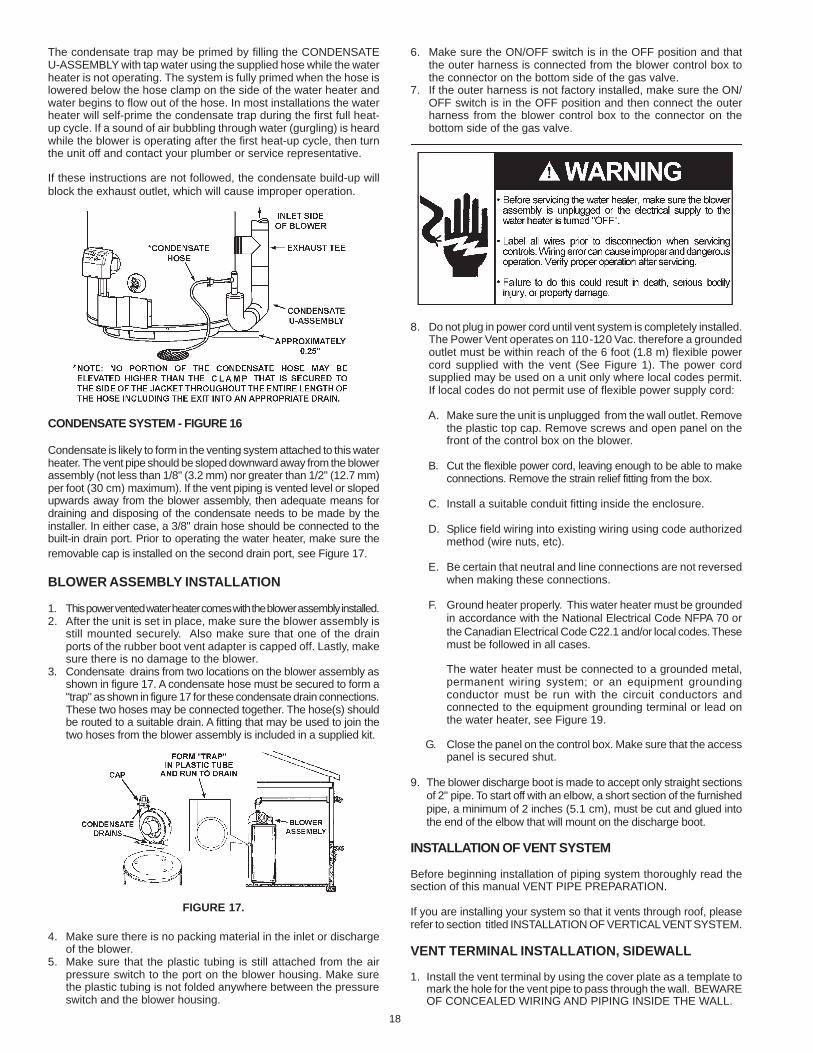
The condensate trap may be primed by filling the CONDENSATEU-ASSEMBLY with tap water using the supplied hose while the waterheater is not operating. The system is fully primed when the hose islowered below the hose clamp on the side of the water heater andwater begins to flow out of the hose. In most installations the waterheater will self-prime the condensate trap during the first full heat-up cycle. If a sound of air bubbling through water (gurgling) is heardwhile the blower is operating after the first heat-up cycle, then turnthe unit off and contact your plumber or service representative.
If these instructions are not followed, the condensate build-up willblock the exhaust outlet, which will cause improper operation.
CONDENSATE SYSTEM - FIGURE 16
Condensate is likely to form in the venting system attached to this waterheater. The vent pipe should be sloped downward away from the blowerassembly (not less than 1/8" (3.2 mm) nor greater than 1/2" (12.7 mm)per foot (30 cm) maximum). If the vent piping is vented level or slopedupwards away from the blower assembly, then adequate means fordraining and disposing of the condensate needs to be made by theinstaller. In either case, a 3/8" drain hose should be connected to thebuilt-in drain port. Prior to operating the water heater, make sure theremovable cap is installed on the second drain port, see Figure 17.
BLOWER ASSEMBLY INSTALLATION
1. This power vented water heater comes with the blower assembly installed.2. After the unit is set in place, make sure the blower assembly is
still mounted securely. Also make sure that one of the drainports of the rubber boot vent adapter is capped off. Lastly, makesure there is no damage to the blower.
3. Condensate drains from two locations on the blower assembly asshown in figure 17. A condensate hose must be secured to form a"trap" as shown in figure 17 for these condensate drain connections.These two hoses may be connected together. The hose(s) shouldbe routed to a suitable drain. A fitting that may be used to join thetwo hoses from the blower assembly is included in a supplied kit.
FIGURE 17.
4. Make sure there is no packing material in the inlet or dischargeof the blower.
5. Make sure that the plastic tubing is still attached from the airpressure switch to the port on the blower housing. Make surethe plastic tubing is not folded anywhere between the pressureswitch and the blower housing.
6. Make sure the ON/OFF switch is in the OFF position and thatthe outer harness is connected from the blower control box tothe connector on the bottom side of the gas valve.
7. If the outer harness is not factory installed, make sure the ON/OFF switch is in the OFF position and then connect the outerharness from the blower control box to the connector on thebottom side of the gas valve.
8. Do not plug in power cord until vent system is completely installed.The Power Vent operates on 110-120 Vac. therefore a groundedoutlet must be within reach of the 6 foot (1.8 m) flexible powercord supplied with the vent (See Figure 1). The power cordsupplied may be used on a unit only where local codes permit.If local codes do not permit use of flexible power supply cord:
A. Make sure the unit is unplugged from the wall outlet. Removethe plastic top cap. Remove screws and open panel on thefront of the control box on the blower.
B. Cut the flexible power cord, leaving enough to be able to makeconnections. Remove the strain relief fitting from the box.
C. Install a suitable conduit fitting inside the enclosure.
D. Splice field wiring into existing wiring using code authorizedmethod (wire nuts, etc).
E. Be certain that neutral and line connections are not reversedwhen making these connections.
F. Ground heater properly. This water heater must be groundedin accordance with the National Electrical Code NFPA 70 orthe Canadian Electrical Code C22.1 and/or local codes. Thesemust be followed in all cases.
The water heater must be connected to a grounded metal,permanent wiring system; or an equipment groundingconductor must be run with the circuit conductors andconnected to the equipment grounding terminal or lead onthe water heater, see Figure 19.
G. Close the panel on the control box. Make sure that the accesspanel is secured shut.
9. The blower discharge boot is made to accept only straight sectionsof 2" pipe. To start off with an elbow, a short section of the furnishedpipe, a minimum of 2 inches (5.1 cm), must be cut and glued intothe end of the elbow that will mount on the discharge boot.
INSTALLATION OF VENT SYSTEM
Before beginning installation of piping system thoroughly read thesection of this manual VENT PIPE PREPARATION.
If you are installing your system so that it vents through roof, pleaserefer to section titled INSTALLATION OF VERTICAL VENT SYSTEM.
VENT TERMINAL INSTALLATION, SIDEWALL
1. Install the vent terminal by using the cover plate as a template tomark the hole for the vent pipe to pass through the wall. BEWAREOF CONCEALED WIRING AND PIPING INSIDE THE WALL.
19
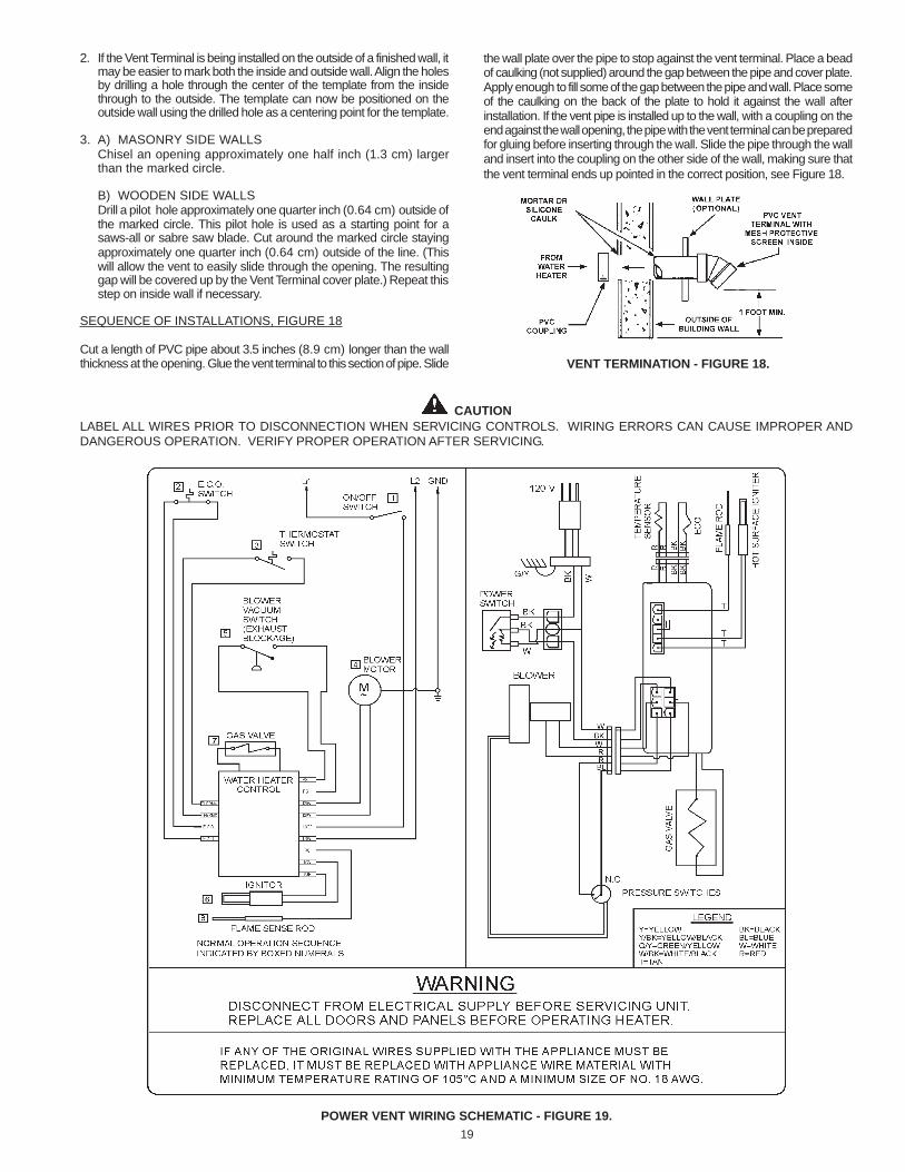
CAUTIONLABEL ALL WIRES PRIOR TO DISCONNECTION WHEN SERVICING CONTROLS. WIRING ERRORS CAN CAUSE IMPROPER ANDDANGEROUS OPERATION. VERIFY PROPER OPERATION AFTER SERVICING.
POWER VENT WIRING SCHEMATIC - FIGURE 19.
2. If the Vent Terminal is being installed on the outside of a finished wall, itmay be easier to mark both the inside and outside wall. Align the holesby drilling a hole through the center of the template from the insidethrough to the outside. The template can now be positioned on theoutside wall using the drilled hole as a centering point for the template.
3. A) MASONRY SIDE WALLSChisel an opening approximately one half inch (1.3 cm) largerthan the marked circle.
B) WOODEN SIDE WALLSDrill a pilot hole approximately one quarter inch (0.64 cm) outside ofthe marked circle. This pilot hole is used as a starting point for asaws-all or sabre saw blade. Cut around the marked circle stayingapproximately one quarter inch (0.64 cm) outside of the line. (Thiswill allow the vent to easily slide through the opening. The resultinggap will be covered up by the Vent Terminal cover plate.) Repeat thisstep on inside wall if necessary.
SEQUENCE OF INSTALLATIONS, FIGURE 18
Cut a length of PVC pipe about 3.5 inches (8.9 cm) longer than the wallthickness at the opening. Glue the vent terminal to this section of pipe. Slide
the wall plate over the pipe to stop against the vent terminal. Place a beadof caulking (not supplied) around the gap between the pipe and cover plate.Apply enough to fill some of the gap between the pipe and wall. Place someof the caulking on the back of the plate to hold it against the wall afterinstallation. If the vent pipe is installed up to the wall, with a coupling on theend against the wall opening, the pipe with the vent terminal can be preparedfor gluing before inserting through the wall. Slide the pipe through the walland insert into the coupling on the other side of the wall, making sure thatthe vent terminal ends up pointed in the correct position, see Figure 18.
VENT TERMINATION - FIGURE 18.
20
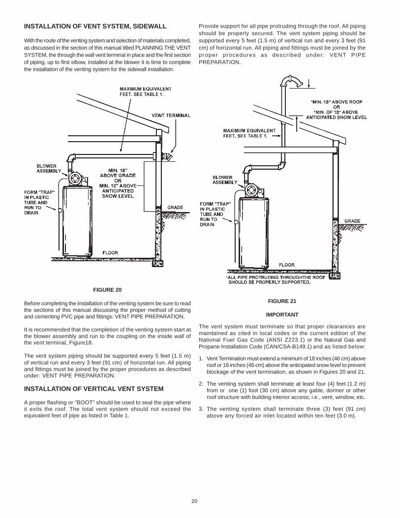
INSTALLATION OF VENT SYSTEM, SIDEWALL
With the route of the venting system and selection of materials completed,as discussed in the section of this manual titled PLANNING THE VENTSYSTEM, the through the wall vent terminal in place and the first sectionof piping, up to first elbow, installed at the blower it is time to completethe installation of the venting system for the sidewall installation.
FIGURE 20
Before completing the installation of the venting system be sure to readthe sections of this manual discussing the proper method of cuttingand cementing PVC pipe and fittings: VENT PIPE PREPARATION.
It is recommended that the completion of the venting system start atthe blower assembly and run to the coupling on the inside wall ofthe vent terminal, Figure18.
The vent system piping should be supported every 5 feet (1.5 m)of vertical run and every 3 feet (91 cm) of horizontal run. All pipingand fittings must be joined by the proper procedures as describedunder: VENT PIPE PREPARATION.
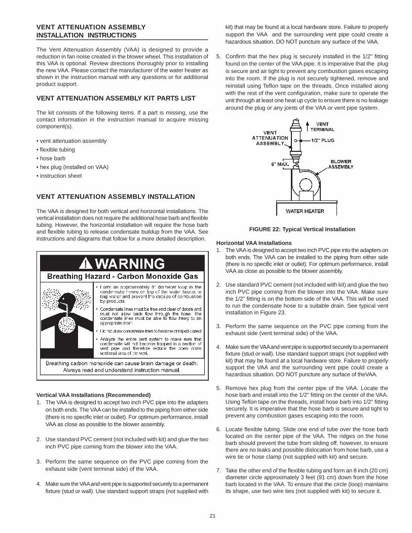
INSTALLATION OF VERTICAL VENT SYSTEM
A proper flashing or "BOOT" should be used to seal the pipe whereit exits the roof. The total vent system should not exceed theequivalent feet of pipe as listed in Table 1.
Provide support for all pipe protruding through the roof. All pipingshould be properly secured. The vent system piping should besupported every 5 feet (1.5 m) of vertical run and every 3 feet (91cm) of horizontal run. All piping and fittings must be joined by theproper procedures as descr ibed under: VENT PIPEPREPARATION.
FIGURE 21
IMPORTANT
The vent system must terminate so that proper clearances aremaintained as cited in local codes or the current edition of theNational Fuel Gas Code (ANSI Z223.1) or the Natural Gas andPropane Installation Code (CAN/CSA-B149.1) and as listed below:
1. Vent Termination must extend a minimum of 18 inches (46 cm) aboveroof or 18 inches (46 cm) above the anticipated snow level to preventblockage of the vent termination, as shown in Figures 20 and 21.
2. The venting system shall terminate at least four (4) feet (1.2 m)from or one (1) foot (30 cm) above any gable, dormer or otherroof structure with building interior access; i.e., vent, window, etc.
3. The venting system shall terminate three (3) feet (91 cm)above any forced air inlet located within ten feet (3.0 m).
21
VENT ATTENUATION ASSEMBLYINSTALLATION INSTRUCTIONS
The Vent Attenuation Assembly (VAA) is designed to provide areduction in fan noise created in the blower wheel. This installation ofthis VAA is optional. Review directions thoroughly prior to installingthe new VAA. Please contact the manufacturer of the water heater asshown in the instruction manual with any questions or for additionalproduct support.
VENT ATTENUATION ASSEMBLY KIT PARTS LIST
The kit consists of the following items. If a part is missing, use thecontact information in the instruction manual to acquire missingcomponent(s).
• vent attenuation assembly• flexible tubing• hose barb• hex plug (installed on VAA)• instruction sheet
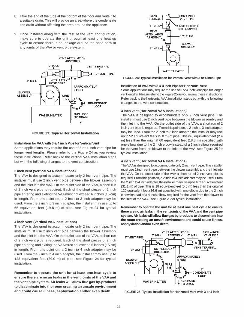
VENT ATTENUATION ASSEMBLY INSTALLATION
The VAA is designed for both vertical and horizontal installations. Thevertical installation does not require the additional hose barb and flexibletubing. However, the horizontal installation will require the hose barband flexible tubing to release condensate buildup from the VAA. Seeinstructions and diagrams that follow for a more detailed description.
Vertical VAA Installations (Recommended)1. The VAA is designed to accept two inch PVC pipe into the adapters
on both ends. The VAA can be installed to the piping from either side(there is no specific inlet or outlet). For optimum performance, installVAA as close as possible to the blower assembly.
2. Use standard PVC cement (not included with kit) and glue the twoinch PVC pipe coming from the blower into the VAA.
3. Perform the same sequence on the PVC pipe coming from theexhaust side (vent terminal side) of the VAA.
4. Make sure the VAA and vent pipe is supported securely to a permanentfixture (stud or wall). Use standard support straps (not supplied with
kit) that may be found at a local hardware store. Failure to properlysupport the VAA and the surrounding vent pipe could create ahazardous situation. DO NOT puncture any surface of the VAA.
5. Confirm that the hex plug is securely installed in the 1/2" fittingfound on the center of the VAA pipe. It is imperative that the plugis secure and air tight to prevent any combustion gases escapinginto the room. If the plug is not securely tightened, remove andreinstall using Teflon tape on the threads. Once installed alongwith the rest of the vent configuration, make sure to operate theunit through at least one heat up cycle to ensure there is no leakagearound the plug or any joints of the VAA or vent pipe system.
FIGURE 22: Typical Vertical Installation
Horizontal VAA Installations1. The VAA is designed to accept two inch PVC pipe into the adapters on
both ends. The VAA can be installed to the piping from either side(there is no specific inlet or outlet). For optimum performance, installVAA as close as possible to the blower assembly.
2. Use standard PVC cement (not included with kit) and glue the twoinch PVC pipe coming from the blower into the VAA. Make surethe 1/2" fitting is on the bottom side of the VAA. This will be usedto run the condensate hose to a suitable drain. See typical ventinstallation in Figure 23.
3. Perform the same sequence on the PVC pipe coming from theexhaust side (vent terminal side) of the VAA.
4. Make sure the VAA and vent pipe is supported securely to a permanentfixture (stud or wall). Use standard support straps (not supplied withkit) that may be found at a local hardware store. Failure to properlysupport the VAA and the surrounding vent pipe could create ahazardous situation. DO NOT puncture any surface of theVAA.
5. Remove hex plug from the center pipe of the VAA. Locate thehose barb and install into the 1/2" fitting on the center of the VAA.Using Teflon tape on the threads, install hose barb into 1/2" fittingsecurely. It is imperative that the hose barb is secure and tight toprevent any combustion gases escaping into the room.
6. Locate flexible tubing. Slide one end of tube over the hose barblocated on the center pipe of the VAA. The ridges on the hosebarb should prevent the tube from sliding off, however, to ensurethere are no leaks and possible dislocation from hose barb, use awire tie or hose clamp (not supplied with kit) and secure.
7. Take the other end of the flexible tubing and form an 8 inch (20 cm)diameter circle approximately 3 feet (91 cm) down from the hosebarb located in the VAA. To ensure that the circle (loop) maintainsits shape, use two wire ties (not supplied with kit) to secure it.
22
8. Take the end of the tube at the bottom of the floor and route it toa suitable drain. This will provide an area where the condensatecan drain without affecting the area around the appliance.
9. Once installed along with the rest of the vent configuration,make sure to operate the unit through at least one heat upcycle to ensure there is no leakage around the hose barb orany joints of the VAA or vent pipe system.
FIGURE 23: Typical Horizontal Installation
Installation for VAA with 3 & 4 inch Pipe for Vertical VentSome applications may require the use of 3 or 4 inch vent pipe forlonger vent lengths. Please refer to the Figure 24 as you reviewthese instructions. Refer back to the vertical VAA installation stepsbut with the following changes to the vent construction.
3 inch vent (Vertical VAA Installations)The VAA is designed to accommodate only 2 inch vent pipe. Theinstaller must use 2 inch vent pipe between the blower assemblyand the inlet into the VAA. On the outlet side of the VAA, a short runof 2 inch vent pipe is required. Each of the short pieces of 2 inchpipe entering and exiting the VAA must not exceed 6 inches (15 cm)in length. From this point on, a 2 inch to 3 inch adapter may beused. From the 2 inch to 3 inch adapter, the installer may use up to65 equivalent feet (19.8 m) of pipe, see Figure 24 for typicalinstallation.
4 inch vent (Vertical VAA Installations)The VAA is designed to accommodate only 2 inch vent pipe. Theinstaller must use 2 inch vent pipe between the blower assemblyand the inlet into the VAA. On the outlet side of the VAA, a short runof 2 inch vent pipe is required. Each of the short pieces of 2 inchpipe entering and exiting the VAA must not exceed 6 inches (15 cm)in length. From this point on, a 2 inch to 4 inch adapter may beused. From the 2 inch to 4 inch adapter, the installer may use up to128 equivalent feet (39.0 m) of pipe, see Figure 24 for typicalinstallation.
Remember to operate the unit for at least one heat cycle toensure there are no air leaks in the vent joints of the VAA andthe vent pipe system. Air leaks will allow flue gas by-productsto disseminate into the room creating an unsafe environmentand could cause illness, asphyxiation and/or even death.
FIGURE 24: Typical Installation for Vertical Vent with 3 or 4 inch Pipe
Installation of VAA with 3 & 4 inch Pipe for Horizontal VentSome applications may require the use of 3 or 4 inch vent pipe for longervent lengths. Please refer to the Figure 25 as you review these instructions.Refer back to the horizontal VAA installation steps but with the followingchanges to the vent construction.
3 inch vent (Horizontal VAA Installations)The VAA is designed to accommodate only 2 inch vent pipe. Theinstaller must use 2 inch vent pipe between the blower assembly andthe inlet into the VAA. On the outlet side of the VAA, a short run of 2inch vent pipe is required. From this point on, a 2 inch to 3 inch adaptermay be used. From the 2 inch to 3 inch adapter, the installer may useup to 52 equivalent feet (15.8 m) of pipe. This is 8 equivalent feet (2.4m) less than the original 60 equivalent feet (18.3 m) specified withone elbow due to the 2 inch elbow instead of a 3 inch elbow requiredfor the vent from the blower to the inlet of the VAA, see Figure 25 fortypical installation.
4 inch vent (Horizontal VAA Installations)The VAA is designed to accommodate only 2 inch vent pipe. The installermust use 2 inch vent pipe between the blower assembly and the inlet intothe VAA. On the outlet side of the VAA a short run of 2 inch vent pipe isrequired. From this point on, a 2 inch to 4 inch adapter may be used. Fromthe 2 inch to 4 inch adapter, the installer may use up to 102 equivalent feet(31.1 m) of pipe. This is 18 equivalent feet (5.5 m) less than the original120 equivalent feet (36.6 m) specified with one elbow due to the 2 inchelbow instead of a 4 inch elbow required for the vent from the blower tothe inlet of the VAA, see Figure 25 for typical installation.
Remember to operate the unit for at least one heat cycle to ensurethere are no air leaks in the vent joints of the VAA and the vent pipesystem. Air leaks will allow flue gas by-products to disseminate intothe room creating an unsafe environment and could cause illness,asphyxiation and/or even death.
FIGURE 25: Typical Installation for Horizontal Vent with 3 or 4 inch
23
VENT PIPE PREPARATION
1. INITIAL PREPARATION
A. Make sure the solvent cement you are planning to use isdesigned for the specific application you are attempting.
B. Know the physical and chemical characteristics and limitations ofthe PVC and CPVC piping materials that you are about to use.
C. Know the reputation of your manufacturer and their products.
D. Know your own qualifications or those of your contractor. Thesolvent welding technique of joining PVC and CPVC pipe is aspecialized skill just as any other pipe fitting technique.
E. Closely supervise the installation and inspect the finishedjob before start-up.
F. Contact the manufacturer, supplier, or competent consultingagency if you have any questions about the application orinstallation of PVC and CPVC pipe.
G. Take the time and effort to do a professional job. Shortcutswill only cause you problems and delays in start-up. By far,the majority of failures in PVC and CPVC systems are theresult of shortcuts and/or improper joining techniques.
2. SELECTION OF MATERIALS
• Cutting Device - Saw or Pipe Cutter
• Deburring Tool, Knife, File, or Beveling Machine (2" and above)
• Brush - Pure Bristle
• Rag - Cotton (Not Synthetic)
• Primer and Cleaner
• Solvent Cement - PVC for PVC Components and CPVC forCPVC Components
• Containers - Metal or Glass to hold Primer and Cement. Selectthe type of PVC or CPVC materials to be used on the basis oftheir application with respect to chemical resistance, pressurerating, temperature characteristics, etc.
• Insertion Tool - Helpful for larger diameter pipe and fittings 6inches (15.2 cm) and above.
PRIMER
It is recommended that Tetrahydrofuran (THF) be used to preparethe surfaces of pipe and fittings for solvent welding. Do not usewater, rags, gasoline or any other substitutes for cleaning PVC orCPVC surfaces. A chemical cleaner such as MEK may be used.
CEMENT
The cement should be a bodied cement of approximately 500 to1600 centipoise viscosity containing 10-20% (by weight) virgin PVCmaterial solvated with tetrahydrofuran (THF). Small quantities ofdimethyl formamide (DMF) may be included to act as a retardingagent to extend curing time. Select the proper cement; Schedule40 cement should be used for Schedule 40 pipe. Never use all-purpose cements, commercial glues and adhesives or ABS cementto join PVC or CPVC pipe and fittings.
APPLICATORS
Select a suitable pure bristle type paint brush. Use a proper widthbrush or roller to apply the primer and cement (see chart below).Speedy application of cement is important due to its fast dryingcharacteristics. IMPORTANT NOTE: A dauber type applicator shouldonly be used on pipe sizes 2" and below. For larger diameter pipe, abrush or roller must be used.
RECOMMENDED BRUSH* SIZE FOR PRIMERAND CEMENT APPLICATIONS
Nominal Pipe Size Brush Width(IPS)
2 1.5" (3.8 cm)3 1.5" - 2.5" (3.8 cm - 6.4 cm)
*USE ONLY NATURAL BRISTLE
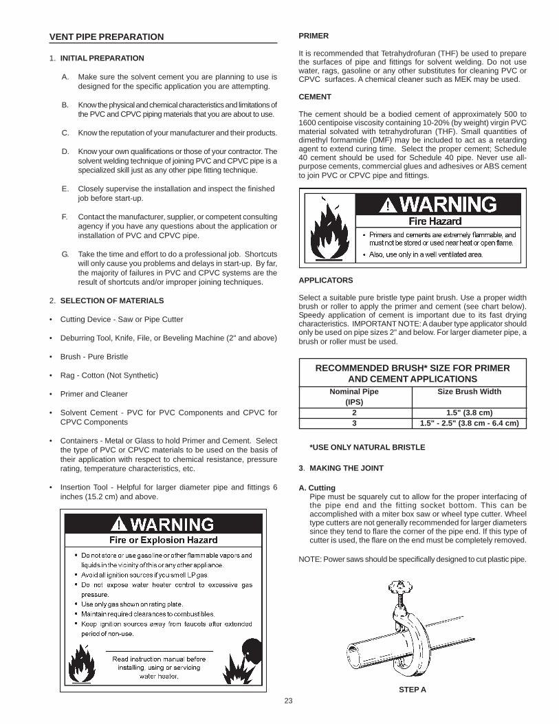
3. MAKING THE JOINT
A. CuttingPipe must be squarely cut to allow for the proper interfacing ofthe pipe end and the fitting socket bottom. This can beaccomplished with a miter box saw or wheel type cutter. Wheeltype cutters are not generally recommended for larger diameterssince they tend to flare the corner of the pipe end. If this type ofcutter is used, the flare on the end must be completely removed.
NOTE: Power saws should be specifically designed to cut plastic pipe.
STEP A
24
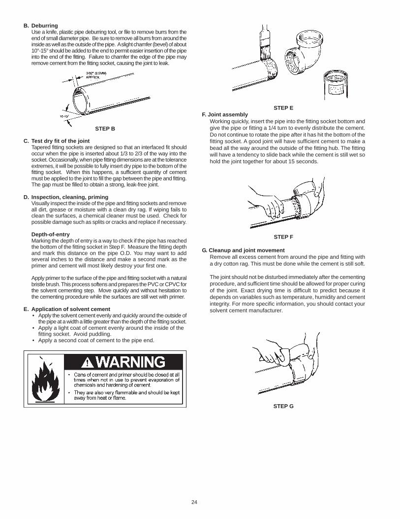
B. DeburringUse a knife, plastic pipe deburring tool, or file to remove burrs from theend of small diameter pipe. Be sure to remove all burrs from around theinside as well as the outside of the pipe. A slight chamfer (bevel) of about10°-15° should be added to the end to permit easier insertion of the pipeinto the end of the fitting. Failure to chamfer the edge of the pipe mayremove cement from the fitting socket, causing the joint to leak.
STEP B
C. Test dry fit of the jointTapered fitting sockets are designed so that an interfaced fit shouldoccur when the pipe is inserted about 1/3 to 2/3 of the way into thesocket. Occasionally, when pipe fitting dimensions are at the toleranceextremes, it will be possible to fully insert dry pipe to the bottom of thefitting socket. When this happens, a sufficient quantity of cementmust be applied to the joint to fill the gap between the pipe and fitting.The gap must be filled to obtain a strong, leak-free joint.
D. Inspection, cleaning, primingVisually inspect the inside of the pipe and fitting sockets and removeall dirt, grease or moisture with a clean dry rag. If wiping fails toclean the surfaces, a chemical cleaner must be used. Check forpossible damage such as splits or cracks and replace if necessary.
Depth-of-entryMarking the depth of entry is a way to check if the pipe has reachedthe bottom of the fitting socket in Step F. Measure the fitting depthand mark this distance on the pipe O.D. You may want to addseveral inches to the distance and make a second mark as theprimer and cement will most likely destroy your first one.
Apply primer to the surface of the pipe and fitting socket with a naturalbristle brush. This process softens and prepares the PVC or CPVC forthe solvent cementing step. Move quickly and without hesitation tothe cementing procedure while the surfaces are still wet with primer.
E. Application of solvent cement• Apply the solvent cement evenly and quickly around the outside of
the pipe at a width a little greater than the depth of the fitting socket.• Apply a light coat of cement evenly around the inside of the
fitting socket. Avoid puddling.• Apply a second coat of cement to the pipe end.
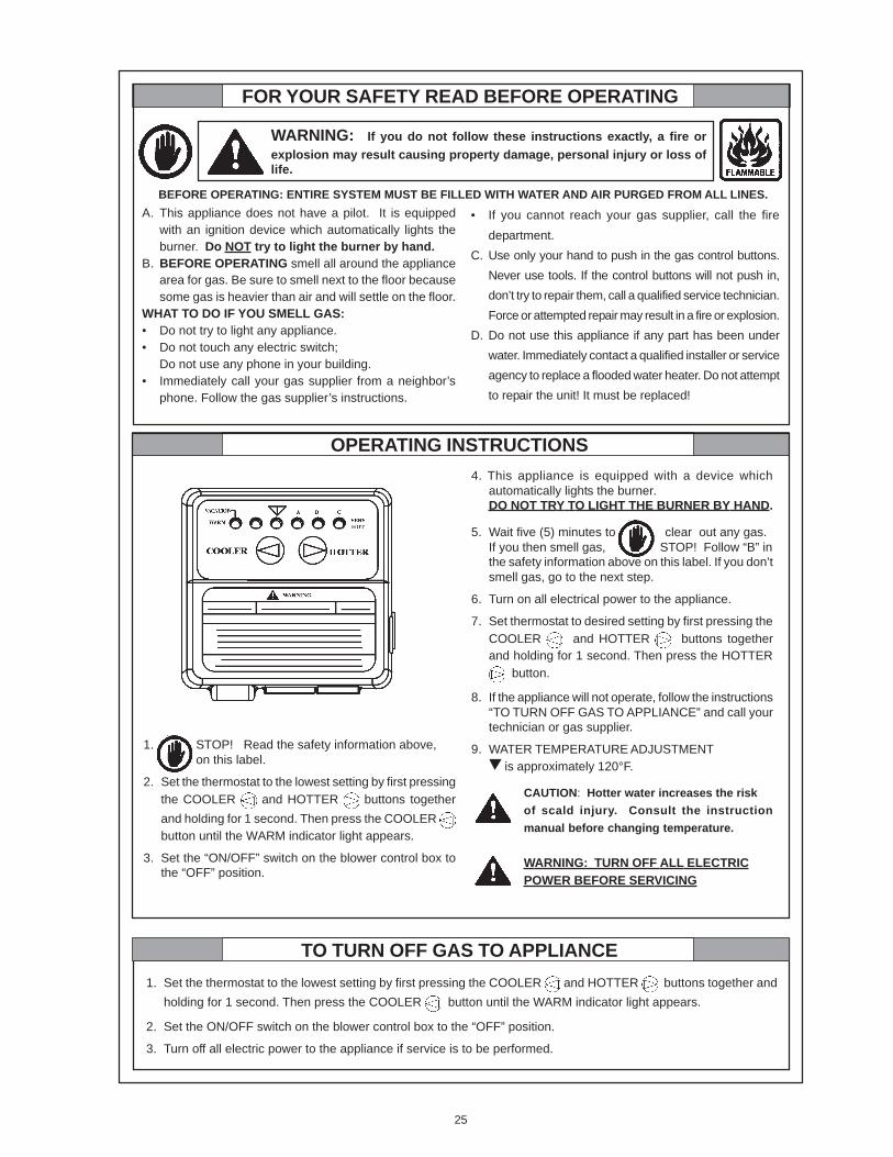
STEP EF. Joint assembly
Working quickly, insert the pipe into the fitting socket bottom andgive the pipe or fitting a 1/4 turn to evenly distribute the cement.Do not continue to rotate the pipe after it has hit the bottom of thefitting socket. A good joint will have sufficient cement to make abead all the way around the outside of the fitting hub. The fittingwill have a tendency to slide back while the cement is still wet sohold the joint together for about 15 seconds.
STEP F
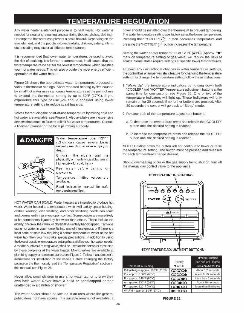
G. Cleanup and joint movementRemove all excess cement from around the pipe and fitting witha dry cotton rag. This must be done while the cement is still soft.
The joint should not be disturbed immediately after the cementingprocedure, and sufficient time should be allowed for proper curingof the joint. Exact drying time is difficult to predict because itdepends on variables such as temperature, humidity and cementintegrity. For more specific information, you should contact yoursolvent cement manufacturer.
STEP G
25
FOR YOUR SAFETY READ BEFORE OPERATING
WARNING: If you do not follow these instructions exactly, a fire orexplosion may result causing property damage, personal injury or loss oflife.
A. This appliance does not have a pilot. It is equippedwith an ignition device which automatically lights theburner. Do NOT try to light the burner by hand.
B. BEFORE OPERATING smell all around the appliancearea for gas. Be sure to smell next to the floor becausesome gas is heavier than air and will settle on the floor.
WHAT TO DO IF YOU SMELL GAS:• Do not try to light any appliance.• Do not touch any electric switch;
Do not use any phone in your building.• Immediately call your gas supplier from a neighbor’s
phone. Follow the gas supplier’s instructions.
• If you cannot reach your gas supplier, call the firedepartment.
C. Use only your hand to push in the gas control buttons.Never use tools. If the control buttons will not push in,don’t try to repair them, call a qualified service technician.Force or attempted repair may result in a fire or explosion.
D. Do not use this appliance if any part has been underwater. Immediately contact a qualified installer or serviceagency to replace a flooded water heater. Do not attemptto repair the unit! It must be replaced!
OPERATING INSTRUCTIONS
1. Set the thermostat to the lowest setting by first pressing the COOLER and HOTTER buttons together andholding for 1 second. Then press the COOLER button until the WARM indicator light appears.
2. Set the ON/OFF switch on the blower control box to the “OFF” position.
3. Turn off all electric power to the appliance if service is to be performed.
BEFORE OPERATING: ENTIRE SYSTEM MUST BE FILLED WITH WATER AND AIR PURGED FROM ALL LINES.
1. STOP! Read the safety information above,on this label.
2. Set the thermostat to the lowest setting by first pressingthe COOLER and HOTTER buttons togetherand holding for 1 second. Then press the COOLER button until the WARM indicator light appears.
3. Set the “ON/OFF” switch on the blower control box tothe “OFF” position.
4. This appliance is equipped with a device whichautomatically lights the burner.DO NOT TRY TO LIGHT THE BURNER BY HAND.
5. Wait five (5) minutes to clear out any gas.If you then smell gas, STOP! Follow “B” inthe safety information above on this label. If you don’tsmell gas, go to the next step.
6. Turn on all electrical power to the appliance.
7. Set thermostat to desired setting by first pressing theCOOLER and HOTTER buttons togetherand holding for 1 second. Then press the HOTTER
button.
8. If the appliance will not operate, follow the instructions“TO TURN OFF GAS TO APPLIANCE” and call yourtechnician or gas supplier.
9. WATER TEMPERATURE ADJUSTMENT is approximately 120°F.
CAUTION: Hotter water increases the riskof scald injury. Consult the instructionmanual before changing temperature.
WARNING: TURN OFF ALL ELECTRICPOWER BEFORE SERVICING
TO TURN OFF GAS TO APPLIANCE
26
Any water heater’s intended purpose is to heat water. Hot water isneeded for cleansing, cleaning, and sanitizing (bodies, dishes, clothing).Untempered hot water can present a scald hazard. Depending on thetime element, and the people involved (adults, children, elderly, infirm,etc.) scalding may occur at different temperatures.
It is recommended that lower water temperatures be used to avoidthe risk of scalding. It is further recommended, in all cases, that thewater temperature be set for the lowest temperature which satisfiesyour hot water needs. This will also provide the most energy efficientoperation of the water heater.
Figure 26 shows the approximate water temperatures produced atvarious thermostat settings. Short repeated heating cycles causedby small hot water uses can cause temperatures at the point of useto exceed the thermostat setting by up to 30°F (17°C). If youexperience this type of use you should consider using lowertemperature settings to reduce scald hazards.
Valves for reducing the point-of-use temperature by mixing cold andhot water are available, see Figure 2. Also available are inexpensivedevices that attach to faucets to limit hot water temperatures. Contacta licensed plumber or the local plumbing authority.
HOT WATER CAN SCALD: Water heaters are intended to produce hotwater. Water heated to a temperature which will satisfy space heating,clothes washing, dish washing, and other sanitizing needs can scaldand permanently injure you upon contact. Some people are more likelyto be permanently injured by hot water than others. These include theelderly, children, the infirm, or physically/mentally handicapped. If anyoneusing hot water in your home fits into one of these groups or if there is alocal code or state law requiring a certain temperature water at the hotwater tap, then you must take special precautions. In addition to usingthe lowest possible temperature setting that satisfies your hot water needs,a means such as a mixing valve, shall be used at the hot water taps usedby these people or at the water heater. Mixing valves are available atplumbing supply or hardware stores, see Figure 2. Follow manufacturer’sinstructions for installation of the valves. Before changing the factorysetting on the thermostat, read the “Temperature Regulation” section inthis manual, see Figure 26.
Never allow small children to use a hot water tap, or to draw theirown bath water. Never leave a child or handicapped personunattended in a bathtub or shower.
The water heater should be located in an area where the generalpublic does not have access. If a suitable area is not available, a
TEMPERATURE REGULATIONcover should be installed over the thermostat to prevent tampering.The water temperature setting was factory set at the lowest temperature;Pressing the “COOLER” button decreases temperature andpressing the “HOTTER” button increases the temperature.
Setting the water heater temperature at 120°F (49°C) (Approx. “ ”mark on temperature setting of gas valve) will reduce the risks ofscalds. Some states require settings at specific lower temperatures.
To avoid any unintentional changes in water temperature settings,the control has a tamper resistant feature for changing the temperaturesetting. To change the temperature setting follow these instructions:
1. “Wake Up” the temperature indicators by holding down both“COOLER” and “HOTTER” temperature adjustment buttons at thesame time for one second, see Figure 26. One or two of thetemperature indicators will light up. These indicators will onlyremain on for 30 seconds if no further buttons are pressed. After30 seconds the control will go back to “Sleep” mode.
2. Release both of the temperature adjustment buttons.
a. To decrease the temperature press and release the “COOLER”button until the desired setting is reached.
b. To increase the temperature press and release the “HOTTER”button until the desired setting is reached.
NOTE: Holding down the button will not continue to lower or raisethe temperature setting. The button must be pressed and releasedfor each temperature change desired.
Should overheating occur or the gas supply fail to shut off, turn offthe manual gas control valve to the appliance.
Time to ProduceDisplay 2nd and 3rd Degree
Temperature Setting A B C Burns on Adult Skin C-Flashing = approx. 160°F (71°C) About 1/2 seconds C = approx. 150°F (66°C) About 1-1/2 seconds B = approx. 140°F (60°C) Less than 5 seconds A = approx. 130°F (54°C) About 30 seconds = approx. 120°F (49°C) More than 5 minutes WARM = approx. 80°F (27°C) - - - - - - - - - - - - -
FIGURE 26.
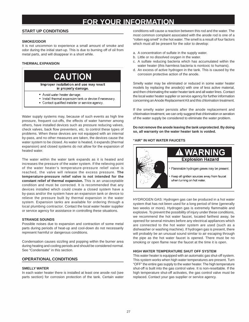
27
FOR YOUR INFORMATIONSTART UP CONDITIONS
SMOKE/ODORIt is not uncommon to experience a small amount of smoke andodor during the initial start-up. This is due to burning off of oil frommetal parts, and will disappear in a short while.
THERMAL EXPANSION
Water supply systems may, because of such events as high linepressure, frequent cut-offs, the effects of water hammer amongothers, have installed devices such as pressure reducing valves,check valves, back flow preventers, etc. to control these types ofproblems. When these devices are not equipped with an internalby-pass, and no other measures are taken, the devices cause thewater system to be closed. As water is heated, it expands (thermalexpansion) and closed systems do not allow for the expansion ofheated water.
The water within the water tank expands as it is heated andincreases the pressure of the water system. If the relieving pointof the water heater ’s temperature-pressure relief valve isreached, the valve will release the excess pressure. Thetemperature-pressure relief valve is not intended for theconstant relief of thermal expansion. This is an unacceptablecondition and must be corrected. It is recommended that anydevices installed which could create a closed system have aby-pass and/or the system have an expansion tank or device torelieve the pressure built by thermal expansion in the watersystem. Expansion tanks are available for ordering through alocal plumbing contractor. Contact the local water heater supplieror service agency for assistance in controlling these situations.
STRANGE SOUNDSPossible noises due to expansion and contraction of some metalparts during periods of heat-up and cool-down do not necessarilyrepresent harmful or dangerous conditions.
Condensation causes sizzling and popping within the burner areaduring heating and cooling periods and should be considered normal.See “Condensate” in this section.
OPERATIONAL CONDITIONS
SMELLY WATERIn each water heater there is installed at least one anode rod (seeparts section) for corrosion protection of the tank. Certain water
conditions will cause a reaction between this rod and the water. Themost common complaint associated with the anode rod is one of a“rotten egg smell” in the hot water. The smell is a result of four factorswhich must all be present for the odor to develop:
a. A concentration of sulfate in the supply water.b. Little or no dissolved oxygen in the water.c. A sulfate reducing bacteria which has accumulated within the
water heater (this harmless bacteria is nontoxic to humans).d. An excess of active hydrogen in the tank. This is caused by the
corrosion protective action of the anode.
Smelly water may be eliminated or reduced in some water heatermodels by replacing the anode(s) with one of less active material,and then chlorinating the water heater tank and all water lines. Contactthe local water heater supplier or service agency for further informationconcerning an Anode Replacement Kit and this chlorination treatment.
If the smelly water persists after the anode replacement andchlorination treatment, we can only suggest that chlorination or aerationof the water supply be considered to eliminate the water problem.
Do not remove the anode leaving the tank unprotected. By doingso, all warranty on the water heater tank is voided.
“AIR” IN HOT WATER FAUCETS
HYDROGEN GAS: Hydrogen gas can be produced in a hot watersystem that has not been used for a long period of time (generallytwo weeks or more). Hydrogen gas is extremely flammable andexplosive. To prevent the possibility of injury under these conditions,we recommend the hot water faucet, located farthest away, beopened for several minutes before any electrical appliances whichare connected to the hot water system are used (such as adishwasher or washing machine). If hydrogen gas is present, therewill probably be an unusual sound similar to air escaping throughthe pipe as the hot water faucet is opened. There must be nosmoking or open flame near the faucet at the time it is open.
HIGH WATER TEMPERATURE SHUT OFF SYSTEMThis water heater is equipped with an automatic gas shut-off system.This system works when high water temperatures are present. Turn“OFF” the entire gas supply to the water heater. The high temperatureshut-off is built into the gas control valve. It is non-resettable. If thehigh temperature shut-off activates, the gas control valve must bereplaced. Contact your gas supplier or service agency.
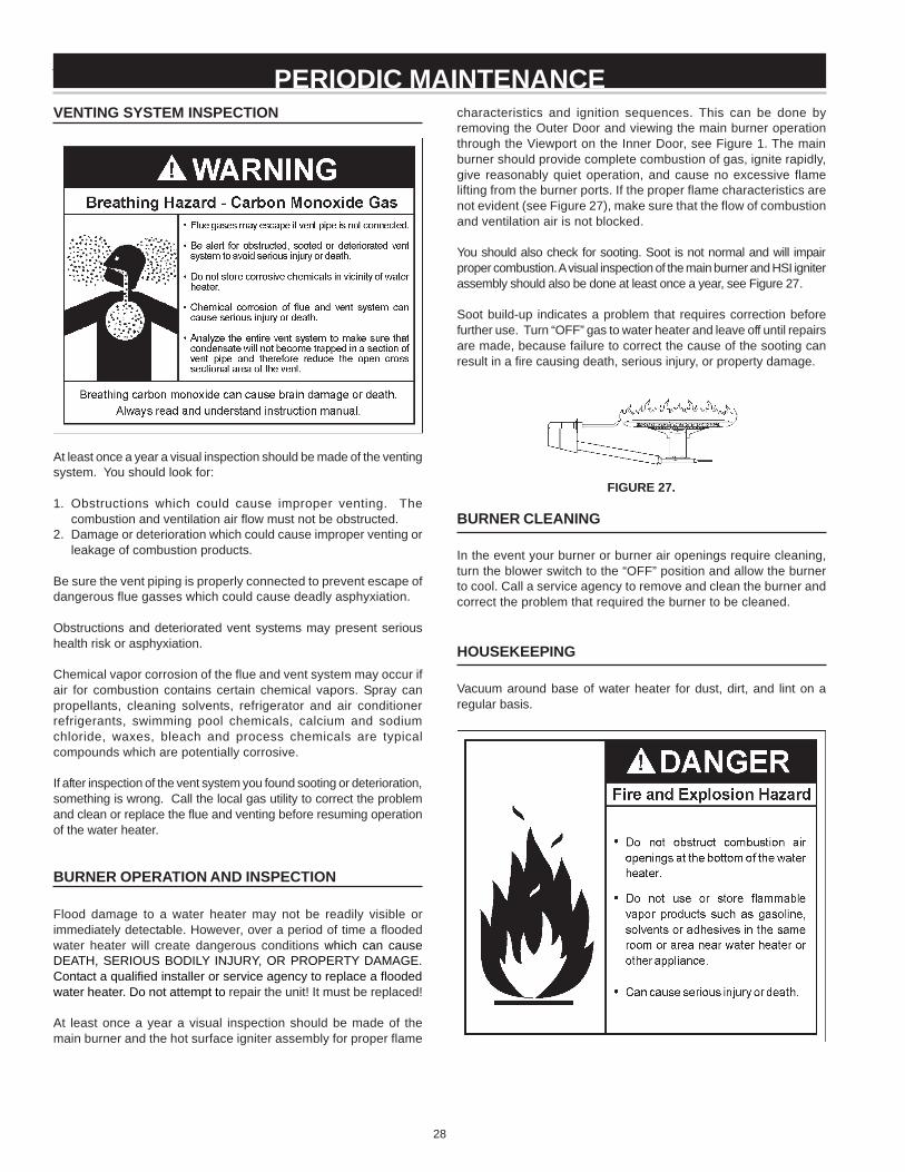
28
VENTING SYSTEM INSPECTION
At least once a year a visual inspection should be made of the ventingsystem. You should look for:
1. Obstructions which could cause improper venting. Thecombustion and ventilation air flow must not be obstructed.
2. Damage or deterioration which could cause improper venting orleakage of combustion products.
Be sure the vent piping is properly connected to prevent escape ofdangerous flue gasses which could cause deadly asphyxiation.
Obstructions and deteriorated vent systems may present serioushealth risk or asphyxiation.
Chemical vapor corrosion of the flue and vent system may occur ifair for combustion contains certain chemical vapors. Spray canpropellants, cleaning solvents, refrigerator and air conditionerrefrigerants, swimming pool chemicals, calcium and sodiumchloride, waxes, bleach and process chemicals are typicalcompounds which are potentially corrosive.
If after inspection of the vent system you found sooting or deterioration,something is wrong. Call the local gas utility to correct the problemand clean or replace the flue and venting before resuming operationof the water heater.
BURNER OPERATION AND INSPECTION
Flood damage to a water heater may not be readily visible orimmediately detectable. However, over a period of time a floodedwater heater will create dangerous conditions which can causeDEATH, SERIOUS BODILY INJURY, OR PROPERTY DAMAGE.Contact a qualified installer or service agency to replace a floodedwater heater. Do not attempt to repair the unit! It must be replaced!
At least once a year a visual inspection should be made of themain burner and the hot surface igniter assembly for proper flame
PERIODIC MAINTENANCEcharacteristics and ignition sequences. This can be done byremoving the Outer Door and viewing the main burner operationthrough the Viewport on the Inner Door, see Figure 1. The mainburner should provide complete combustion of gas, ignite rapidly,give reasonably quiet operation, and cause no excessive flamelifting from the burner ports. If the proper flame characteristics arenot evident (see Figure 27), make sure that the flow of combustionand ventilation air is not blocked.
You should also check for sooting. Soot is not normal and will impairproper combustion. A visual inspection of the main burner and HSI igniterassembly should also be done at least once a year, see Figure 27.
Soot build-up indicates a problem that requires correction beforefurther use. Turn “OFF” gas to water heater and leave off until repairsare made, because failure to correct the cause of the sooting canresult in a fire causing death, serious injury, or property damage.
FIGURE 27.
BURNER CLEANING
In the event your burner or burner air openings require cleaning,turn the blower switch to the “OFF” position and allow the burnerto cool. Call a service agency to remove and clean the burner andcorrect the problem that required the burner to be cleaned.
HOUSEKEEPING
Vacuum around base of water heater for dust, dirt, and lint on aregular basis.
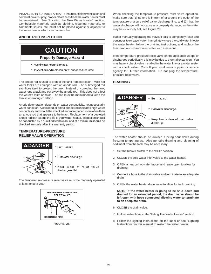
29
INSTALLED IN SUITABLE AREA: To insure sufficient ventilation andcombustion air supply, proper clearances from the water heater mustbe maintained. See “Locating the New Water Heater” section.Combustible materials such as clothing, cleaning materials, orflammable liquids, etc. must not be placed against or adjacent tothe water heater which can cause a fire.
ANODE ROD INSPECTION
The anode rod is used to protect the tank from corrosion. Most hotwater tanks are equipped with an anode rod. The submerged rodsacrifices itself to protect the tank. Instead of corroding the tank,water ions attack and eat away the anode rod. This does not affectthe water’s taste or color. The rod must be maintained to keep thetank in operating condition.
Anode deterioration depends on water conductivity, not necessarilywater condition. A corroded or pitted anode rod indicates high waterconductivity and should be checked and/or replaced more often thanan anode rod that appears to be intact. Replacement of a depletedanode rod can extend the life of your water heater. Inspection shouldbe conducted by a qualified technician, and at a minimum should bechecked annually after the warranty period.
TEMPERATURE-PRESSURERELIEF VALVE OPERATION
The temperature-pressure relief valve must be manually operatedat least once a year.
FIGURE 28.
When checking the temperature-pressure relief valve operation,make sure that (1) no one is in front of or around the outlet of thetemperature-pressure relief valve discharge line, and (2) that thewater discharge will not cause any property damage, as the watermay be extremely hot, see Figure 28.
If after manually operating the valve, it fails to completely reset andcontinues to release water, immediately close the cold water inlet tothe water heater, follow the draining instructions, and replace thetemperature-pressure relief valve with a new one.
If the temperature-pressure relief valve on the appliance weeps ordischarges periodically, this may be due to thermal expansion. Youmay have a check valve installed in the water line or a water meterwith a check valve. Consult your local water supplier or serviceagency for further information. Do not plug the temperature-pressure relief valve.
DRAINING
The water heater should be drained if being shut down duringfreezing temperatures. Also periodic draining and cleaning ofsediment from the tank may be necessary.
1. Set the blower switch to the “OFF” position.
2. CLOSE the cold water inlet valve to the water heater.
3. OPEN a nearby hot water faucet and leave open to allow fordraining.
4. Connect a hose to the drain valve and terminate to an adequatedrain.
5. OPEN the water heater drain valve to allow for tank draining.
NOTE: If the water heater is going to be shut down anddrained for an extended period, the drain valve should beleft open with hose connected allowing water to terminateto an adequate drain.
6. CLOSE the drain valve.
7. Follow instructions in the “Filling The Water Heater” section.
8. Follow the lighting instructions on the label or see “LightingInstructions” in this manual to restart the water heater.
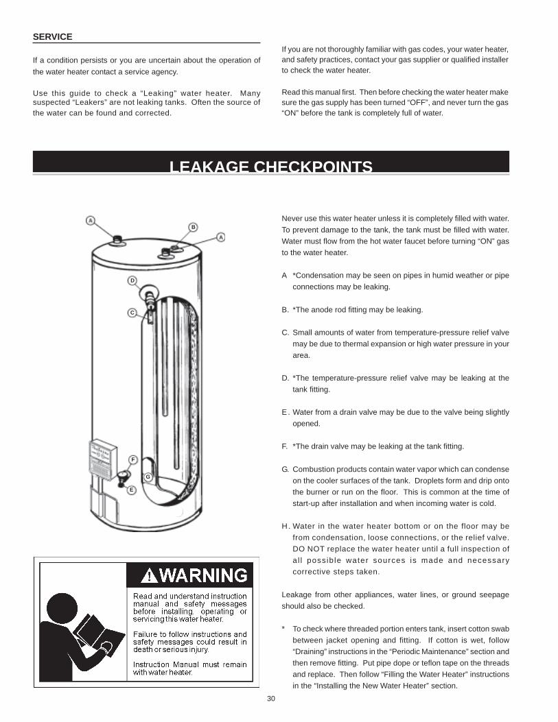
30
LEAKAGE CHECKPOINTS
Never use this water heater unless it is completely filled with water.To prevent damage to the tank, the tank must be filled with water.Water must flow from the hot water faucet before turning “ON” gasto the water heater.
A *Condensation may be seen on pipes in humid weather or pipeconnections may be leaking.
B. *The anode rod fitting may be leaking.
C. Small amounts of water from temperature-pressure relief valvemay be due to thermal expansion or high water pressure in yourarea.
D. *The temperature-pressure relief valve may be leaking at thetank fitting.
E . Water from a drain valve may be due to the valve being slightlyopened.
F. *The drain valve may be leaking at the tank fitting.
G. Combustion products contain water vapor which can condenseon the cooler surfaces of the tank. Droplets form and drip ontothe burner or run on the floor. This is common at the time ofstart-up after installation and when incoming water is cold.
H . Water in the water heater bottom or on the floor may befrom condensation, loose connections, or the relief valve.DO NOT replace the water heater until a full inspection ofa l l possib le water sources is made and necessarycorrective steps taken.
Leakage from other appliances, water lines, or ground seepageshould also be checked.
* To check where threaded portion enters tank, insert cotton swabbetween jacket opening and fitting. If cotton is wet, follow“Draining” instructions in the “Periodic Maintenance” section andthen remove fitting. Put pipe dope or teflon tape on the threadsand replace. Then follow “Filling the Water Heater” instructionsin the “Installing the New Water Heater” section.
SERVICE
If a condition persists or you are uncertain about the operation ofthe water heater contact a service agency.
Use this guide to check a “Leaking” water heater. Manysuspected “Leakers” are not leaking tanks. Often the source ofthe water can be found and corrected.
If you are not thoroughly familiar with gas codes, your water heater,and safety practices, contact your gas supplier or qualified installerto check the water heater.
Read this manual first. Then before checking the water heater makesure the gas supply has been turned “OFF”, and never turn the gas“ON” before the tank is completely full of water.
B
D
C
F
G
E
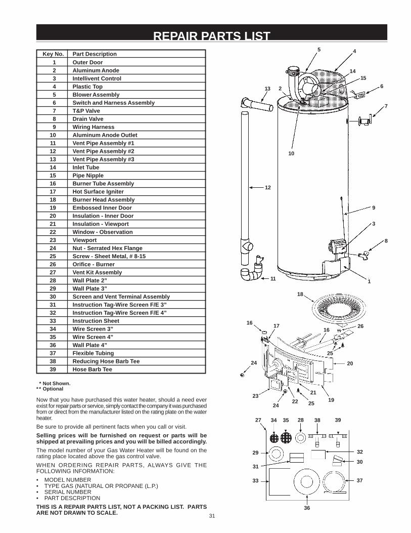
31
Key No. Part Description1 Outer Door2 Aluminum Anode3 Intellivent Control4 Plastic Top5 Blower Assembly6 Switch and Harness Assembly7 T&P Valve8 Drain Valve9 Wiring Harness
10 Aluminum Anode Outlet11 Vent Pipe Assembly #112 Vent Pipe Assembly #213 Vent Pipe Assembly #314 Inlet Tube15 Pipe Nipple16 Burner Tube Assembly17 Hot Surface Igniter18 Burner Head Assembly19 Embossed Inner Door20 Insulation - Inner Door21 Insulation - Viewport22 Window - Observation23 Viewport24 Nut - Serrated Hex Flange25 Screw - Sheet Metal, # 8-1526 Orifice - Burner27 Vent Kit Assembly28 Wall Plate 2”29 Wall Plate 3”30 Screen and Vent Terminal Assembly31 Instruction Tag-Wire Screen F/E 3”32 Instruction Tag-Wire Screen F/E 4”33 Instruction Sheet34 Wire Screen 3”35 Wire Screen 4”36 Wall Plate 4”37 Flexible Tubing38 Reducing Hose Barb Tee39 Hose Barb Tee
REPAIR PARTS LIST
* Not Shown.* * Optional
Now that you have purchased this water heater, should a need everexist for repair parts or service, simply contact the company it was purchasedfrom or direct from the manufacturer listed on the rating plate on the waterheater.Be sure to provide all pertinent facts when you call or visit.Selling prices will be furnished on request or parts will beshipped at prevailing prices and you will be billed accordingly.The model number of your Gas Water Heater will be found on therating place located above the gas control valve.WHEN ORDERING REPAIR PARTS, ALWAYS GIVE THEFOLLOWING INFORMATION:• MODEL NUMBER• TYPE GAS (NATURAL OR PROPANE (L.P.)• SERIAL NUMBER• PART DESCRIPTIONTHIS IS A REPAIR PARTS LIST, NOT A PACKING LIST. PARTSARE NOT DRAWN TO SCALE.
2
10
1
8
3
9
7
6
45
16 17
18
1921
2223
24 25
24
27 2834
2930
31
32
35
36
37
38
13
12
11
1415
16 26
20
25
33
39
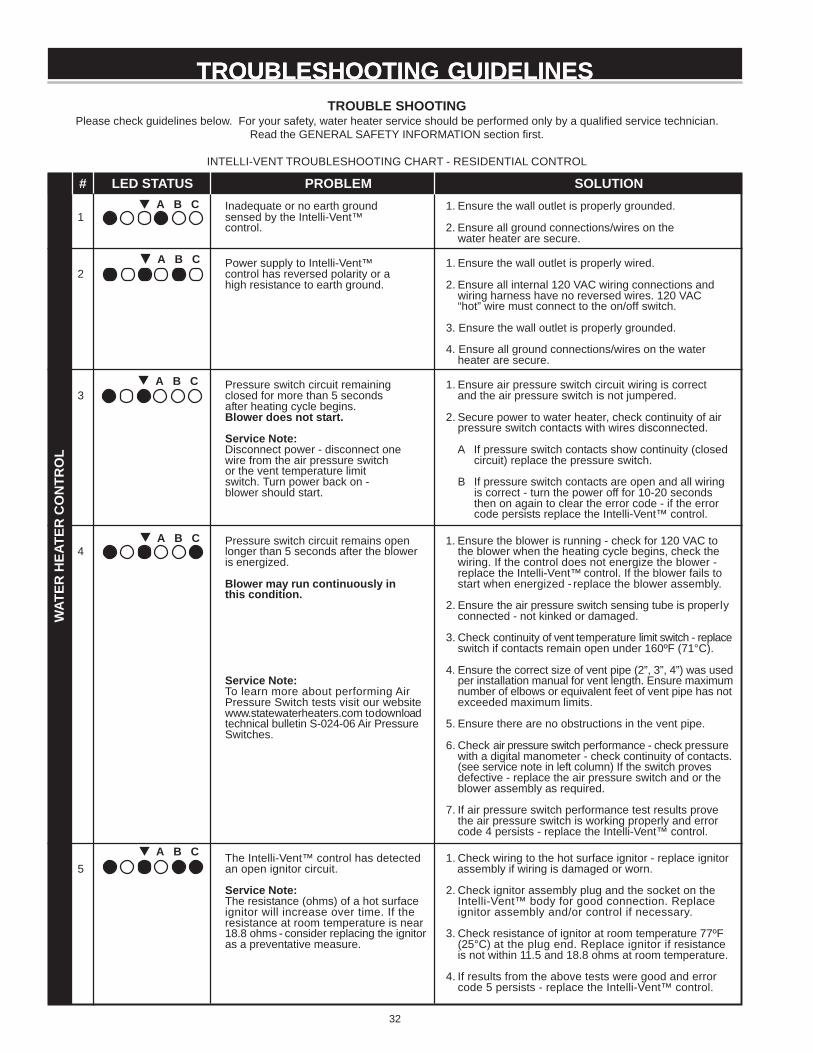
32
TROUBLESHOOTING GUIDELINESTROUBLESHOOTING GUIDELINESTROUBLE SHOOTING
Please check guidelines below. For your safety, water heater service should be performed only by a qualified service technician.Read the GENERAL SAFETY INFORMATION section first.
INTELLI-VENT TROUBLESHOOTING CHART - RESIDENTIAL CONTROL
PROBLEM SOLUTIONInadequate or no earth ground 1. Ensure the wall outlet is properly grounded.
1 sensed by the Intelli-Vent™control. 2. Ensure all ground connections/wires on the
water heater are secure.
Power supply to Intelli-Vent™ 1. Ensure the wall outlet is properly wired.2 control has reversed polarity or a
high resistance to earth ground. 2. Ensure all internal 120 VAC wiring connections andwiring harness have no reversed wires. 120 VAC“hot” wire must connect to the on/off switch.
3. Ensure the wall outlet is properly grounded.
4. Ensure all ground connections/wires on the waterheater are secure.
Pressure switch circuit remaining 1. Ensure air pressure switch circuit wiring is correct3 closed for more than 5 seconds and the air pressure switch is not jumpered.
after heating cycle begins.Blower does not start. 2. Secure power to water heater, check continuity of air
pressure switch contacts with wires disconnected.Service Note:Disconnect power - disconnect one A If pressure switch contacts show continuity (closedwire from the air pressure switch circuit) replace the pressure switch.or the vent temperature limitswitch. Turn power back on - B If pressure switch contacts are open and all wiringblower should start. is correct - turn the power off for 10-20 seconds
then on again to clear the error code - if the errorcode persists replace the Intelli-Vent™ control.
Pressure switch circuit remains open 1. Ensure the blower is running - check for 120 VAC to4 longer than 5 seconds after the blower the blower when the heating cycle begins, check the
is energized. wiring. If the control does not energize the blower -replace the Intelli-Vent™ control. If the blower fails to
Blower may run continuously in start when energized - replace the blower assembly.this condition.
2. Ensure the air pressure switch sensing tube is properlyconnected - not kinked or damaged.
3. Check continuity of vent temperature limit switch - replaceswitch if contacts remain open under 160ºF (71°C).
4. Ensure the correct size of vent pipe (2”, 3”, 4”) was usedService Note: per installation manual for vent length. Ensure maximumTo learn more about performing Air number of elbows or equivalent feet of vent pipe has notPressure Switch tests visit our website exceeded maximum limits.www.statewaterheaters.com to downloadtechnical bulletin S-024-06 Air Pressure 5. Ensure there are no obstructions in the vent pipe.Switches.
6. Check air pressure switch performance - check pressurewith a digital manometer - check continuity of contacts.(see service note in left column) If the switch provesdefective - replace the air pressure switch and or theblower assembly as required.
7. If air pressure switch performance test results provethe air pressure switch is working properly and errorcode 4 persists - replace the Intelli-Vent™ control.
The Intelli-Vent™ control has detected 1. Check wiring to the hot surface ignitor - replace ignitor5 an open ignitor circuit. assembly if wiring is damaged or worn.
Service Note: 2. Check ignitor assembly plug and the socket on theThe resistance (ohms) of a hot surface Intelli-Vent™ body for good connection. Replaceignitor will increase over time. If the ignitor assembly and/or control if necessary.resistance at room temperature is near18.8 ohms - consider replacing the ignitor 3. Check resistance of ignitor at room temperature 77ºFas a preventative measure. (25°C) at the plug end. Replace ignitor if resistance
is not within 11.5 and 18.8 ohms at room temperature.
4. If results from the above tests were good and errorcode 5 persists - replace the Intelli-Vent™ control.
A B C
A B C
A B C
A B C
A B C
# LED STATUS
WAT
ER H
EATE
R C
ON
TRO
L
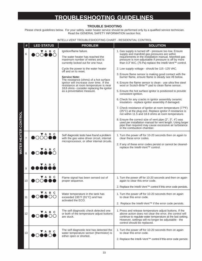
33
TROUBLESHOOTING GUIDELINESTROUBLE SHOOTING
Please check guidelines below. For your safety, water heater service should be performed only by a qualified service technician.Read the GENERAL SAFETY INFORMATION section first.
INTELLI-VENT TROUBLESHOOTING CHART - RESIDENTIAL CONTROL
PROBLEM SOLUTIONIgnition/flame failure. 1. Gas supply is turned off - pressure too low. Ensure
6 supply and manifold gas pressures are withinThe water heater has reached the requirements in the installation manual. Manifold gasmaximum number of retries and is pressure is non-adjustable if pressure is off by morecurrently locked out for one hour. than 0.3” W.C. (75 Pa) replace the Intelli-Vent™ control.
Cycle the power to the water heater 2. Low supply voltage - should be 115 -125 VAC.off and on to reset.
3. Ensure flame sensor is making good contact with theService Note: burner flame, ensure flame is steady see #8 below.The resistance (ohms) of a hot surfaceignitor will increase over time. If the 4. Ensure the flame sensor is clean - use ultra fine steelresistance at room temperature is near wool or Scotch-Brite™ pad to clean flame sensor.18.8 ohms - consider replacing the ignitoras a preventative measure. 5. Ensure the hot surface ignitor is positioned to provide
consistent ignition.
6. Check for any cracks in ignitor assembly ceramicinsulators - replace ignitor assembly if damaged.
7. Check resistance of ignitor at room temperature (77ºF)(25°C) at the plug end. Replace ignitor if resistance isnot within 11.5 and 18.8 ohms at room temperature.
8. Ensure the correct size of vent pipe (2”, 3”, 4”) wasused per installation manual for vent length. Using largerpipe than required may cause excessive air turbulancein the combustion chamber.
Self diagnostic tests have found a problem 1. Turn the power off for 10-20 seconds then on again to7 with the gas valve driver circuit, internal clear these error codes.
microprocessor, or other internal circuits.2. If any of these error codes persist or cannot be cleared-
replace the Intelli-Vent™ control.
8
9
Flame signal has been sensed out of 1. Turn the power off for 10-20 seconds and then on again10 proper sequence. again to clear this error code.
2. Replace the Intelli-Vent™ control if this error code persists.
Water temperature in the tank has 1. Turn the power off for 10-20 seconds then on again11 exceeded 195°F (91°C) and has to clear this error code.
activated the ECO.2. Replace the Intelli-Vent™ if the error code persists.
The self diagnostic check detected one 1. Press and release temperature adjust buttons. If the12 or both of the temperature adjust buttons above action does not clear the error, the control will
are stuck. continue to regulate water temperature at the last setting.However, settings will no longer be adjustable - thecontrol should be replaced.
The self diagnostic test has detected the 1. Turn the power off for 10-20 seconds then on again13 water temperature sensor (thermistor) is to clear this error code.
either open or shorted.2. Replace the Intelli-Vent™ control if this error code persist.
A B C
A B C
A B C
# LED STATUS
WAT
ER H
EATE
R C
ON
TRO
L
A B C
A B C
A B C
A B C
A B C
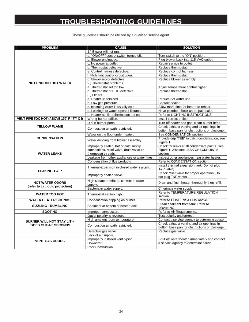
34
These guidelines should be utilized by a qualified service agent.
TROUBLESHOOTING GUIDELINESTROUBLESHOOTING GUIDELINES
PROBLEM CAUSE SOLUTION 1.) Blower will not run. a. “ON/OFF” control switch turned off. Turn switch to the “ON” position. b. Blower unplugged. Plug blower back into 115 VAC outlet. c. No power at outlet. Repair service to outlet. d. Thermostat defective. Replace thermostat. e. Control harness defective. Replace control harness. f. High limit control circuit open. Replace thermostat. g. Blower motor defective. Replace blower assembly. 2.) Thermostat problems a. Thermostat set too low. Adjust temperature control higher. b. Thermostat or ECO defective. Replace thermostat. 3.) Others a. Heater undersized. Reduce hot water use. b. Low gas pressure. Contact dealer. c. Incoming water is usually cold. Allow more time for heater to reheat. d. Leaking hot water pipes of fixtures. Have plumber check and repair leaks.
NOT ENOUGH HOT WATER
e. Heater not lit or thermostat not on. Refer to LIGHTING INSTRUCTIONS. VENT PIPE TOO HOT (ABOVE 170° F [ 77° C ]) Wrong burner orifice. Install correct orifice.
Dirt in burner ports. Turn off heater and gas, clean burner head. YELLOW FLAME Combustion air path restricted. Check exhaust venting and air openings in
bottom base pan for obstructions or blockage. Water on the floor under heater. See CONDENSATION section.
CONDENSATION Water dripping from blower assembly. Provide drip “TEE” to catch condensation, see Figure 1.
Improperly sealed, hot or cold supply connections, relief valve, drain valve or thermostat threads.
Check for leaks at all condensate points. See Figure 1. Also see LEAK CHECKPOINTS section.
Leakage from other appliances or water lines. Inspect other appliances near water heater. WATER LEAKS
Condensation of flue products. Refer to CONDENSATION section.
Thermal expansion in closed water system. Install thermal expansion tank (Do not plug T&P valve). LEAKING T & P
Improperly sealed valve. Check relief valve for proper operation (Do not plug T&P valve).
High sulfate or mineral content in water supply. Drain and flush heater thoroughly then refill. HOT WATER ODORS
(refer to cathodic protection) Bacteria in water supply. Chlorinate water supply.
WATER TOO HOT Thermostat set too high. Refer to TEMPERATURE REGULATION section.
WATER HEATER SOUNDS Condensation dripping on burner. Refer to CONDENSATION above.
SIZZLING - RUMBLING Sediment at bottom of heater tank. Clean sediment from tank. Refer to DRAINING.
SOOTING Improper combustion. Refer to Air Requirements. Outlet polarity is reversed. Test polarity and correct. High ambient room temperature. Contact a service agency to determine cause.
Combustion air path restricted. Check exhaust venting and air openings in bottom base pan for obstructions or blockage.
BURNER WILL NOT STAY LIT – GOES OUT 4-5 SECONDS
Defective gas valve. Replace gas valve. Lack of air supply. Improperly installed vent piping. Downdraft VENT GAS ODORS
Poor Combustion
Shut off water heater immediately and contact a service agency to determine cause.
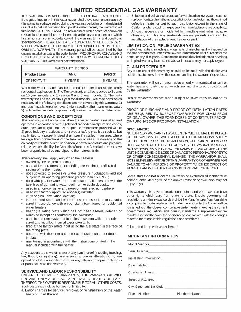
35
THIS WARRANTY IS APPLICABLE TO THE ORIGINAL OWNER ONLY.If the glass lined tank in this water heater shall prove upon examination by(the warrantor) to have leaked during the warranty period in normal residentialuse, due to natural corrosion from potable water therein, the warrantor willfurnish the ORIGINAL OWNER a replacement water heater of equivalentsize and current model, or a replacement part for any component part whichfails in normal use, in accordance with the warranty terms and conditionsspecified below. THE WATER HEATER REPLACEMENT MODEL OR PARTWILL BE WARRANTED FOR ONLY THE UNEXPIRED PORTION OF THEORIGINAL WARRANTY. The warranty period will be determined by theoriginal installation date of the water heater. PROOF-OF-PURCHASE ANDPROOF-OF-INSTALLATION ARE NECESSARY TO VALIDATE THISWARRANTY. This warranty is not transferable.
WARRANTY PERIOD
Product Line TANK1 PARTS2
GP650YTVIT 6 YEARS 6 YEARS
When the water heater has been used for other than single familyresidential application: 1. The Tank warranty shall be reduced to 3 yearson 10 year models and 1 year on 6 and 8 year models. 2. The partswarranty shall be reduced to 1 year for all models. Returned parts whichmeet any of the following conditions are not covered by this warranty: 1)improper installation or removal; 2) damaged by other than normal wear;3) replaced for cosmetic purposes; or 4) returned with defaced date codes.
CONDITIONS AND EXCEPTIONSThis warranty shall apply only when the water heater is installed andoperated in accordance with: 1) all local fire codes and plumbing codes,ordinances and regulations; 2) the printed instructions provided with it;3) good industry practices; and 4) proper safety practices such as butnot limited to a properly sized drain pan if installed in an area whereleakage from connections of the tank would result in damage to thearea adjacent to the heater. In addition, a new temperature and pressurerelief valve, certified by the Canadian Standards Association must havebeen properly installed and piped to the nearest drain.
This warranty shall apply only when the heater is:• owned by the original purchaser;• used at temperatures not exceeding the maximum calibrated
setting of its thermostat;• not subjected to excessive water pressure fluctuations and not
subject to an operating pressure greater than 150 P.S.I.;• filled with potable water, free to circulate at all times and with the
tank free of damaging water sediment or scale deposits;• used in a non-corrosive and non-contaminated atmosphere;• used with factory approved anode(s) installed;• in its original installation location;• in the United States and its territories or possessions or Canada;• sized in accordance with proper sizing techniques for residential
water heaters;• bearing a rating plate which has not been altered, defaced or
removed except as required by the warrantor;• used in an open system or in a closed system with a properly
sized and installed thermal expansion tank;• fired at the factory rated input using the fuel stated in the face of
the rating plate;• operated with the inner and outer combustion chamber doors
in place;• maintained in accordance with the instructions printed in the
manual included with the heater.
Any accident to the water heater or any part thereof (including freezing,fire, floods, or lightning), any misuse, abuse or alteration of it, anyoperation of it in a modified form, or any attempt to repair tank leaksor parts, will void this warranty.
SERVICE AND LABOR RESPONSIBILITYUNDER THIS LIMITED WARRANTY, THE WARRANTOR WILLPROVIDE ONLY A REPLACEMENT WATER HEATER OR PARTTHEREOF. THE OWNER IS RESPONSIBLE FOR ALL OTHER COSTS.Such costs may include but are not limited to:a. Labor charges for service, removal, or reinstallation of the water
heater or part thereof.
LIMITED RESIDENTIAL GAS WARRANTYb. Shipping and delivery charges for forwarding the new water heater or
replacement part from the nearest distributor and returning the claimeddefective heater or part to such distributor except in the state ofCalifornia where such charges are the manufacturer’s responsibility.
c. All cost necessary or incidental for handling and administrativecharges, and for any materials and/or permits required forinstallation of the replacement heater or part.
LIMITATION ON IMPLIED WARRANTIESImplied warranties, including any warranty of merchantability imposed onthe sale of this heater under state law are limited to one year duration for theheater or any of its parts. Some states do not allow limitations on how longan implied warranty lasts, so the above limitations may not apply to you.
CLAIM PROCEDUREAny claim under this warranty should be initiated with the dealer whosold the heater, or with any other dealer handling the warrantor’s products.
The warrantor will only honor replacement with identical or similarwater heater or parts thereof which are manufactured or distributedby the warrantor.
Dealer replacements are made subject to in-warranty validation bywarrantor.
PROOF-OF-PURCHASE AND PROOF-OF-INSTALLATION DATESARE REQUIRED TO SUPPORT WARRANTY FOR CLAIM FROMORIGINAL OWNER. THIS FORM DOES NOT CONSTITUTE PROOF-OF-PURCHASE OR PROOF-OF-INSTALLATION.
DISCLAIMERSNO EXPRESS WARRANTY HAS BEEN OR WILL BE MADE IN BEHALFOF THE WARRANTOR WITH RESPECT TO THE MERCHANTABILITYOF THE HEATER OR THE INSTALLATION, OPERATION, REPAIR ORREPLACEMENT OF THE HEATER OR PARTS. THE WARRANTOR SHALLNOT BE RESPONSIBLE FOR WATER DAMAGE, LOSS OF USE OF THEUNIT, INCONVENIENCE, LOSS OR DAMAGE TO PERSONAL PROPERTY,OR OTHER CONSEQUENTIAL DAMAGE. THE WARRANTOR SHALLNOT BE LIABLE BY VIRTUE OF THIS WARRANTY OR OTHERWISE FORDAMAGE TO ANY PERSONS OR PROPERTY, WHETHER DIRECT ORINDIRECT, AND WHETHER ARISING IN CONTRACT OR IN TORT.
Some states do not allow the limitation or exclusion of incidental orconsequential damages, so the above limitation or exclusion may notapply to you.
This warranty gives you specific legal rights, and you may also haveother rights which vary from state to state. Should governmentalregulations or industry standards prohibit the Manufacturer from furnishinga comparable model replacement under this warranty, the Owner will befurnished with the closest comparable water heater meeting the currentgovernmental regulations and industry standards. A supplementary feemay be assessed to cover the additional cost associated with the changesmade to meet applicable regulations and standards.
Fill out and keep with water heater.
IMPORTANT INFORMATION
Model Number____________________________________________
Serial Number_____________________________________________
Installation Information:
Date Installed _____________________________________________
Company’s Name _________________________________________
Street or P.O. Box _________________________________________
City, State, and Zip Code ___________________________________
Phone Number _______________Plumber’s Name_______________

36
Related Documents