July 2017 ResidenƟal Electric Water Heater InstallaƟon InstrucƟons and Use & Care Guide Keep this manual in the pocket on heater for future reference whenever maintenance, adjustment or service is required. Retain your original receipt as proof of purchase. DO NOT RETURN THIS UNIT TO THE STORE Read this manual and the labels on the water heater before you install, operate, or service it. If you have difficulty following the direcƟons, or aren’t sure you can safely and properly do any of this work yourself: • Call our Technical Assistance Hotline at 1-877-817-6750 or visit http:// www. AOSmithAtLowes.com . We can help you with installation, operations, trouble- shooting, or maintenance. Before you call, write down the model and serial number from the water heater’s data plate. • Call your Lowe’s® store to have this water heater installed. Lowe’s® Professional Installation is available for this product and the work is guaranteed. Incorrect installaƟon, operaƟon, or service can damage the water heater, your house and other property, and present risks including fire, scalding, electric shock, and explosion, causing serious injury or death. Table of Contents Page IMPORTANT SAFETY INFORMATION ................................. 3 GETTING STARTED ............................................................ 6 INSTALLATION ................................................................... 7 TROUBLESHOOTING ....................................................... 16 MAINTENANCE ............................................................... 19 REPAIR PARTS .......................................................... 22 WIRE DIAGRAM .............................................................. 23 100288224 (REV A)/2000546003

Welcome message from author
This document is posted to help you gain knowledge. Please leave a comment to let me know what you think about it! Share it to your friends and learn new things together.
Transcript
July 2017
Residen al ElectricWater Heater
Installa on Instruc ons and Use & Care Guide
Keep this manual in the pocket on heater for future reference whenever maintenance, adjustment or service is required.Retain your original receipt as proof of purchase.
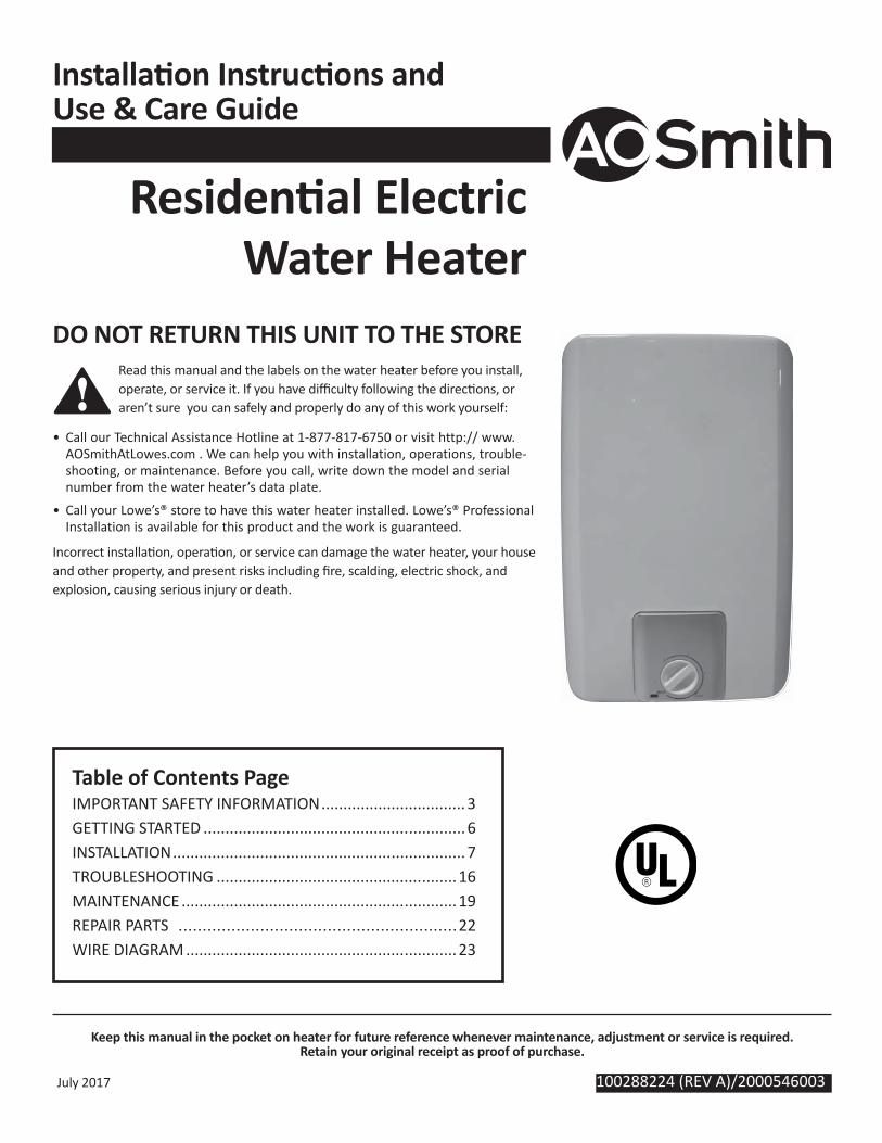
DO NOT RETURN THIS UNIT TO THE STORE Read this manual and the labels on the water heater before you install, operate, or service it. If you have diffi culty following the direc ons, or aren’t sure you can safely and properly do any of this work yourself:
• Call our Technical Assistance Hotline at 1-877-817-6750 or visit http:// www.AOSmithAtLowes.com . We can help you with installation, operations, trouble-shooting, or maintenance. Before you call, write down the model and serial number from the water heater’s data plate.
• Call your Lowe’s® store to have this water heater installed. Lowe’s® Professional Installation is available for this product and the work is guaranteed.
Incorrect installa on, opera on, or service can damage the water heater, your house and other property, and present risks including fi re, scalding, electric shock, and explosion, causing serious injury or death.
Table of Contents PageIMPORTANT SAFETY INFORMATION .................................3GETTING STARTED ............................................................6INSTALLATION ...................................................................7TROUBLESHOOTING .......................................................16MAINTENANCE ...............................................................19REPAIR PARTS ..........................................................22WIRE DIAGRAM ..............................................................23
100288224 (REV A)/2000546003
2 • Electric Mini Tank Water Heater
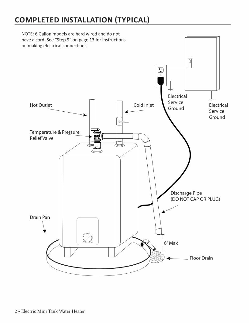
COMPLETED INSTALLATION TYPICAL
MAX
1
2
125°F
Hot Outlet Cold Inlet
Temperature & Pressure Relief Valve
Discharge Pipe(DO NOT CAP OR PLUG)
Floor Drain
6” Max
Drain Pan
Electrical Service Ground
Electrical Service Ground
NOTE: 6 Gallon models are hard wired and do not have a cord. See “Step 9” on page 13 for instruc ons on making electrical connec ons.
Electric Mini Tank Water Heater • 3
SAFE
TY
IMPORTANT SAFETY INFORMATION
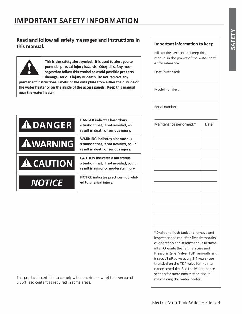
Important informa on to keep
Fill out this sec on and keep thismanual in the pocket of the water heat-er for reference.
Date Purchased:
Model number:
Serial number:
Maintenance performed:* Date:
This is the safety alert symbol. It is used to alert you topoten al physical injury hazards. Obey all safety mes-sages that follow this symbol to avoid possible property damage, serious injury or death. Do not remove any
permanent instruc ons, labels, or the data plate from either the outside of the water heater or on the inside of the access panels. Keep this manual near the water heater.
DANGER
Read and follow all safety messages and instruc ons in this manual.
DANGER indicates hazardous situa on that, if not avoided, will result in death or serious injury.
WARNINGWARNING indicates a hazardous situa on that, if not avoided, could result in death or serious injury.
CAUTIONCAUTION indicates a hazardous situa on that, if not avoided, could result in minor or moderate injury.
NOTICENOTICE indicates prac ces not relat-ed to physical injury.
*Drain and fl ush tank and remove and inspect anode rod a er fi rst six months of opera on and at least annually there-a er. Operate the Temperature and Pressure Relief Valve (T&P) annually and inspect T&P valve every 2-4 years (see the label on the T&P valve for mainte-nance schedule). See the Maintenance sec on for more informa on about maintaining this water heater.This product is certified to comply with a maximum weighted average of
0.25% lead content as required in some areas.
4 • Electric Mini Tank Water Heater
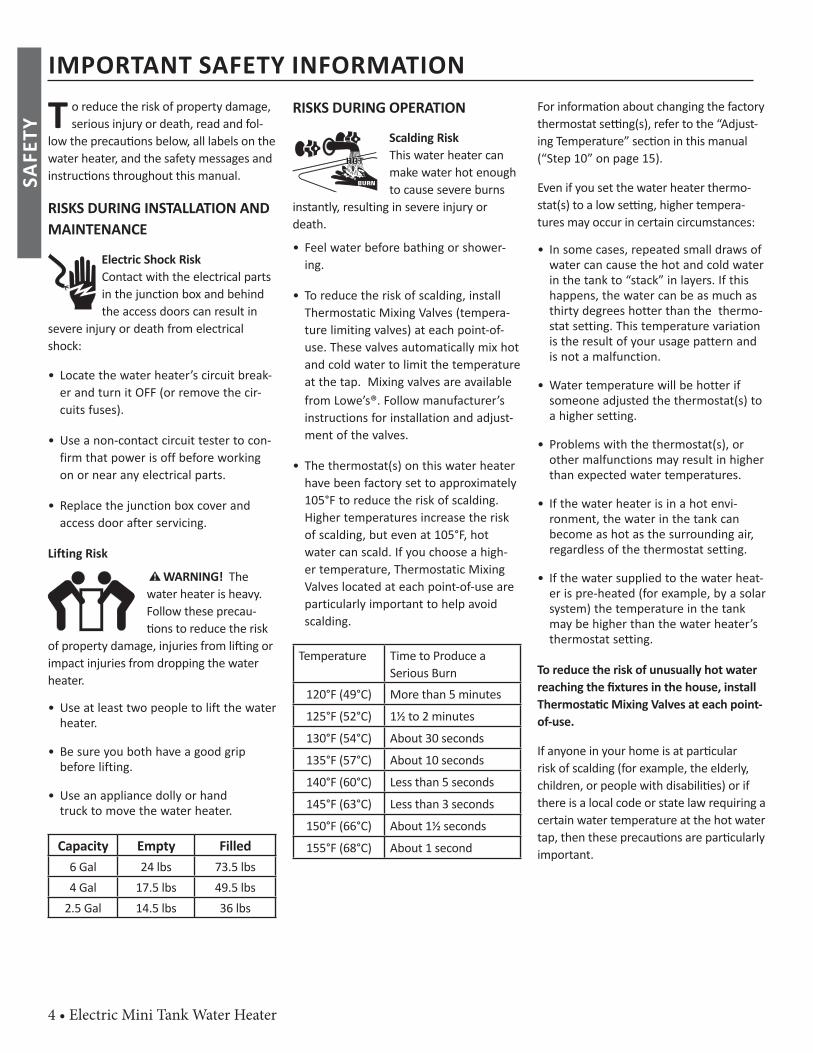
T o reduce the risk of property damage, serious injury or death, read and fol-
low the precau ons below, all labels on the water heater, and the safety messages and instruc ons throughout this manual.
RISKS DURING INSTALLATION AND MAINTENANCE
Electric Shock RiskContact with the electrical parts in the junction box and behind the access doors can result in
severe injury or death from electrical shock:
• Locate the water heater’s circuit break-er and turn it OFF (or remove the cir-cuits fuses).
• Use a non-contact circuit tester to con-firm that power is off before working on or near any electrical parts.
• Replace the junction box cover and access door after servicing.
Lifting Risk
WARNING! The water heater is heavy. Follow these precau- ons to reduce the risk
of property damage, injuries from li ing or impact injuries from dropping the water heater.
• Use at least two people to lift the water heater.
• Be sure you both have a good grip before lifting.
• U se an appliance dolly or hand truck to move the water heater.
Capacity Empty Filled6 Gal 24 lbs 73.5 lbs4 Gal 17.5 lbs 49.5 lbs
2.5 Gal 14.5 lbs 36 lbs
RISKS DURING OPERATION
Scalding RiskThis water heater can make water hot enough to cause severe burns
instantly, resulting in severe injury or death.
• Feel water before bathing or s hower-ing.
• To reduce the risk of scalding, install Thermostatic Mixing Valves (tempera-ture limiting valves) at each point-of-use. These valves automatically mix hot and cold water to limit the temperature at the tap. Mixing valves are available from Lowe’s®. Follow manufacturer’s instructions for installation and adjust-ment of the valves.
• The thermostat(s) on this water heater have been factory set to approximately 105°F to reduce the risk of scalding. Higher temperatures increase the risk of scalding, but even at 105°F, hot water can scald. If you choose a high-er temperature, Thermostatic Mixing Valves located at each point-of-use are particularly important to help avoid scalding.
Temperature Time to Produce a Serious Burn
120°F (49°C) More than 5 minutes125°F (52°C) 1½ to 2 minutes130°F (54°C) About 30 seconds135°F (57°C) About 10 seconds140°F (60°C) Less than 5 seconds145°F (63°C) Less than 3 seconds150°F (66°C) About 1½ seconds155°F (68°C) About 1 second
For informa on about changing the factory thermostat se ng(s), refer to the “Adjust-ing Temperature” sec on in this manual (“Step 10” on page 15).
Even if you set the water heater thermo-stat(s) to a low se ng, higher tempera-tures may occur in certain circumstances:
• In some cases, repeated small draws of water can cause the hot and cold water in the tank to “stack” in layers. If this happens, the water can be as much as thirty degrees hotter than the thermo-stat setting. This temperature variation is the result of your usage pattern and is not a malfunction.
• Water temperature will be hotter if someone adjusted the thermostat(s) to a higher setting.
• Problems with the thermostat(s), or other malfunctions may result in higher than expected water temperatures.
• If the water heater is in a hot envi-ronment, the water in the tank can become as hot as the surrounding air, regardless of the thermostat setting.
• If the water supplied to the water heat-er is pre-heated (for example, by a solar system) the temperature in the tank may be higher than the water heater’s thermostat setting.
To reduce the risk of unusually hot water reaching the fi xtures in the house, install Thermosta c Mixing Valves at each point-of-use.
If anyone in your home is at par cular risk of scalding (for example, the elderly, children, or people with disabili es) or if there is a local code or state law requiring a certain water temperature at the hot water tap, then these precau ons are par cularly important.
IMPORTANT SAFETY INFORMATIONSA
FETY
Electric Mini Tank Water Heater • 5
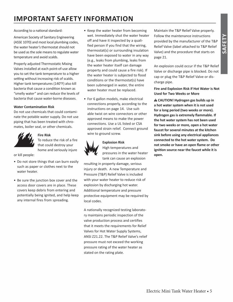
According to a na onal standard:
American Society of Sanitary Engineering (ASSE 1070) and most local plumbing codes, the water heater’s thermostat should not be used as the sole means to regulate water temperature and avoid scalds.
Properly adjusted Thermosta c Mixing Valves installed at each point-of-use allow you to set the tank temperature to a higher se ng without increasing risk of scalds. Higher tank temperatures (140°F) also kill bacteria that cause a condi on known as “smelly water” and can reduce the levels of bacteria that cause water-borne diseases.
Water Contamination RiskDo not use chemicals that could contami-nate the potable water supply. Do not use piping that has been treated with chro-mates, boiler seal, or other chemicals.
Fire RiskTo reduce the risk of a fire that could destroy your home and seriously injure
or kill people:
• D o not store things that can burn easily such as paper or clothes next to the water heater.
• Be sure the junction box cover and the access door covers are in place. These covers keep debris from entering and potentially being ignited, and help keep any internal fires from spreading.
• Keep the water heater from becoming wet. Immediately shut the water heater off and have it inspected by a quali-fied person if you find that the wiring, thermostat(s) or surrounding insulation have been exposed to water in any way (e.g., leaks from plumbing, leaks from the water heater itself can damage property and could cause a fire risk). If the water heater is subjected to flood conditions or the thermostat(s) have been submerged in water, the entire water heater must be replaced.
• For 6 gallon models, make electrical connections properly, according to the instructions on page 14. Use suit-able twist on wire connectors or other approved means to make the power connections. Use a UL listed or CSA approved strain relief. Connect ground wire to ground screw.
Explosion RiskHigh temperatures and pressures in the water heater tank can cause an explosion
resulting in property damage, serious injury or death. A new Temperature and Pressure (T&P) Relief Valve is included with your water heater to reduce risk of explosion by discharging hot water. Additional temperature and pressure protective equipment may be required by local codes.
A nationally recognized testing laborato-ry maintains periodic inspection of the valve production process and certifies that it meets the requirements for Relief Valves for Hot Water Supply Systems, ANSI Z21.22. The T&P Relief Valve’s relief pressure must not exceed the working pressure rating of the water heater as stated on the rating plate.
Maintain the T&P Relief Valve properly. Follow the maintenance instructions provided by the manufacturer of the T&P Relief Valve (label attached to T&P Relief Valve) and the procedure that starts on page 21.
An explosion could occur if the T&P Relief Valve or discharge pipe is blocked. Do not cap or plug the T&P Relief Valve or dis-charge pipe.
Fire and Explosion Risk if Hot Water is Not Used for Two Weeks or More
C AUTION! Hydrogen gas builds up in a hot water system when it is not used for a long period (two weeks or more). Hydrogen gas is extremely fl ammable. If the hot water system has not been used for two weeks or more, open a hot water faucet for several minutes at the kitchen sink before using any electrical appliances connected to the hot water system. Do not smoke or have an open fl ame or other igni on source near the faucet while it is open.
IMPORTANT SAFETY INFORMATION
SAFE
TY
6 • Electric Mini Tank Water Heater
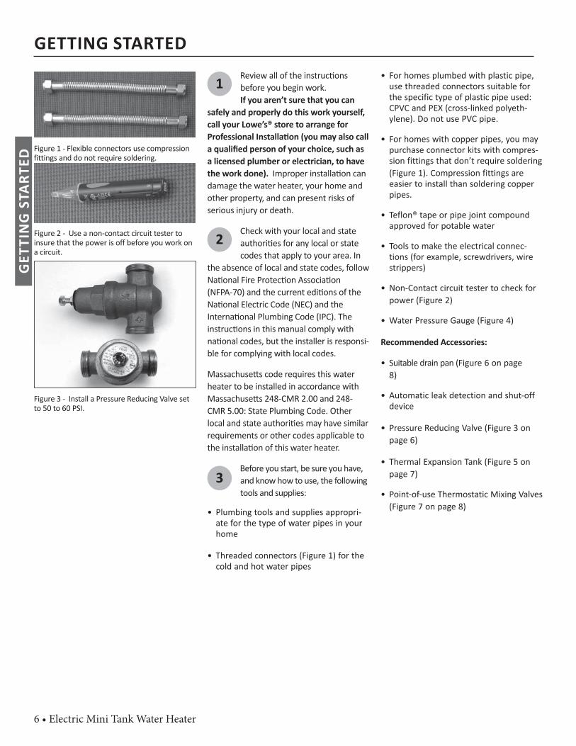
Figure 1 - Flexible connectors use compression fittings and do not require soldering.
Figure 2 - Use a non-contact circuit tester to insure that the power is off before you work on a circuit.
Figure 3 - Install a Pressure Reducing Valve set to 50 to 60 PSI.
1 Review all of the instruc ons before you begin work. If you aren’t sure that you can
safely and properly do this work yourself, call your Lowe’s® store to arrange for Professional Installa on (you may also call a qualifi ed person of your choice, such as a licensed plumber or electrician, to have the work done). Improper installa on can damage the water heater, your home and other property, and can present risks of serious injury or death.
2Check with your local and state authori es for any local or state codes that apply to your area. In
the absence of local and state codes, follow Na onal Fire Protec on Associa on (NFPA-70) and the current edi ons of the Na onal Electric Code (NEC) and the Interna onal Plumbing Code (IPC). The instruc ons in this manual comply with na onal codes, but the installer is responsi-ble for complying with local codes.
Massachuse s code requires this water heater to be installed in accordance with Massachuse s 248-CMR 2.00 and 248-CMR 5.00: State Plumbing Code. Other local and state authori es may have similar requirements or other codes applicable to the installa on of this water heater.
3Before you start, be sure you have, and know how to use, the following tools and supplies:
• Plumbing tools and supplies appropri-ate for the type of water pipes in your home
• Threaded connectors (Figure 1) for the cold and hot water pipes
• For homes plumbed with plastic pipe, use threaded connectors suitable for the specific type of plastic pipe used: CPVC and PEX (cross-linked polyeth-ylene). Do not use PVC pipe.
• For homes with copper pipes, you may purchase connector kits with compres-sion fittings that don’t require soldering (Figure 1). Compression fittings are easier to install than soldering copper pipes.
• Teflon® tape or pipe joint compound approved for potable water
• Tools to make the electrical connec-tions (for example, screwdrivers, wire strippers)
• Non-Contact circuit tester to check for power (Figure 2)
• Water Pressure Gauge (Figure 4)
Recommended Accessories:
• Suitable drain pan (Figure 6 on page 8)
• Automatic leak detection and shut-off device
• Pressure Reducing Valve (Figure 3 on page 6)
• Thermal Expansion Tank (Figure 5 on page 7)
• Point-of-use Thermostatic Mixing Valves (Figure 7 on page 8)
GETTING STARTEDG
ETTI
NG
STA
RTED

Electric Mini Tank Water Heater • 7
Completely read all instruc ons before beginning. If you are not sure if you can complete the installa on, DO NOT RETURN THIS UNIT TO THE STORE. Seek assistance from any of the following sources: Schedule an appointment with a qualified person to install your water heater. Follow these steps for properinstalla on:
Step 1:
✓ Verify that your home is equipped
and up-to-date forproper opera onInstalling a new water heater is the perfect me to examine your home’s plumbing sys-
tem and make sure the system is up to cur-rent code standards. There have likely been plumbing code changes since the old water heater was installed. We recommend installing the following accessories and any other needed changes to bring your home up to the latest code requirements.
Use the checklist below and inspect your home. Install any devices you need to com-ply with codes and assure that your new water heater performs at its best. Check with your local plumbing offi cial for more informa on.
✓ Water pressureWe recommend checking your
home’s water pressure with a pressure gauge (Figure 4.) Most codes allow a maximum incoming water pressure of 80 psi. We recommend a working pressure no higher than 50-60 psi.
HOW: Purchase an inexpensive water pressure gauge available at Lowe’s®. Connect the Water Pressure Gauge to an outside faucet and measure the maximum water pressure experienced throughout the day (highest water pressures o en occur at night).
Figure 4 - Use a Water Pressure Gauge to make sure your home’s water pressure is not too high. To limit your home’s water pressure: Lo-cate your home’s Pressure Reducing Valve (PRV) on the main incoming (cold) water supply line and adjust the water pressure control to between 50 and 60 psi. If your home does not have a Pressure Reducing Valve, install a PRV on the home’s main water supply line and set it to between 50 and 60 psi. Pressure Reducing Valves are available at Lowe’s®.
BACKGROUND: Over the years, many u li es have increased water supply pressures so they can serve more homes. In some homes today, pressures exceed 100 psi. High water pressures can damage water heaters, causing premature leaks. If you have replaced toilet valves, had a wa-ter heater leak, or had to repair applianc-es connected to the plumbing system, pay par cular a en on to your home’s water pressure. When purchasing a PRV, make sure the PRV has a built-in bypass.
✓ Water pressureincrease caused by
thermal expansion Verify that you have a properly sized Thermal Expansion Tank (Figure 5). We recommend installing an expansion tank if your home does not have one. Codes require a properly pressurized, properly sized Thermal Expansion Tank in almost all homes. (See photo on inside front cover.)
Figure 5 - A Thermal Expansion Tank helps pro-tect the home’s plumbing system from pressure spikes.
INSTALLATION
INST
ALLA
TIO
N
8 • Electric Mini Tank Water Heater
HOW: Connect the Thermal Expansion Tank (available at Lowe’s® ) to the cold wa-ter supply line near the water heater. The expansion tank contains a bladder and an air charge. To work properly, the Thermal Expansion Tank must be sized according to the water heater’s tank capacity and pressurized to match the home’s incoming water pressure. Refer to the installa on instruc ons provided with the Thermal Expansion Tank for installa on details.BACKGROUND: Water expands when heated, and the increased volume of water must have a place to go, or thermal expansion will cause large increases in wa-ter pressure (despite the use of a Pressure Reducing Valve on the home’s main water supply line). The Safe Drinking Water Act of 1974 requires the use of backfl ow pre-venters and check valves to restrict water from your home reentering the public water system. Backfl ow preventers are o en installed in water meters and may not be readily visible. As a result, most all plumbing systems today are now “closed,” and almost all homes now need a Thermal Expansion Tank.
A Thermal Expansion Tank is a prac -cal and inexpensive way to help avoid damage to the water heater, washing machine, dishwasher, ice maker and even toilet valves. If your toilet occasionally runs for no apparent reason (usually brief-ly at night), that may be due to thermal expansion increasing the water pressure temporarily.
Water pipe and tank leaks Leaks from plumbing pipes or from the water heater itself can damage property and could cause a fi re risk. • Install an automatic leak detection and
shutoff device (available at Lowe’s® ). These devices can detect water leaks and can shut off the water heater’s water supply if a leak occurs.
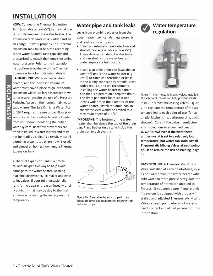
• Install a suitable drain pan (available at Lowe’s®) under the water heater (Fig-ure 6) to catch condensation or leaks in the piping connections or tank. Most codes require, and we recommend, installing the water heater in a drain pan that is piped to an adequate drain. The drain pan must be at least two inches wider than the diameter of the water heater. Install the drain pan so the water level would be limited to a maximum depth of 1-3/4”.
IMPORTANT: The bottom of the water heater shall be above the top of the drain pan. Place heater on a stand inside the drain pan to achieve this.
MAX
1
2
125°F
Figure 6 - A suitable drain pan piped to an adequate drain can help protect flooring from leaks and drips.
✓ Water temperature regula on
Figure 7 - Thermostatic Mixing Valves installed at each point -of-use can help prevent scalds.Install Thermosta c Mixing Valves (Figure 7) to regulate the temperature of the wa-ter supplied to each point-of-use (for ex-ample, kitchen sink, bathroom sink, bath, shower). Consult the valve manufactur-er’s instruc ons or a qualifi ed person.
WARNING! Even if the water heat-er thermostat is set to a rela vely low temperature, hot water can scald. Install Thermosta c Mixing Valves at each point-of-use to reduce the risk of scalding (page 4).
BACKGROUND: A Thermosta c Mixing Valve, installed at each point-of-use, mix-es hot water from the water heater with cold water to more precisely regulate the temperature of hot water supplied to fi xtures. If you aren’t sure if your plumb-ing system is equipped with properly in-stalled and adjusted Thermosta c Mixing Valves at each point where hot water is used, contact a qualifi ed person for more informa on.
INSTALLATIONIN
STAL
LATI
ON
Electric Mini Tank Water Heater • 9
Step 2:
Verify that the loca on is appropriatePlacement of water heater is very im-portant to consider, for the safety and economical use of the appliance.Before installing your water heater, ensure that:
1The water heater will be:• Installed indoors close to the center of the plumbing
system.
• In a suitable drain pan piped to an adequate floor drain or external to the building (Figure 6 on page 8).
• In an area that will not freeze
• In an area that is suitable for installing the water heater vertically
2The loca on has adequate space (clearances) for periodic servic-ing.
3The selected wall or cabinet must be capable of suppor ng at least two mes the weight of the
water heater when fi lled with water (see weight table on page 4).
4The water heater must be installed in a ver cal posi on with water inlet and outlet
connec ons facing upwards and easily accesible.
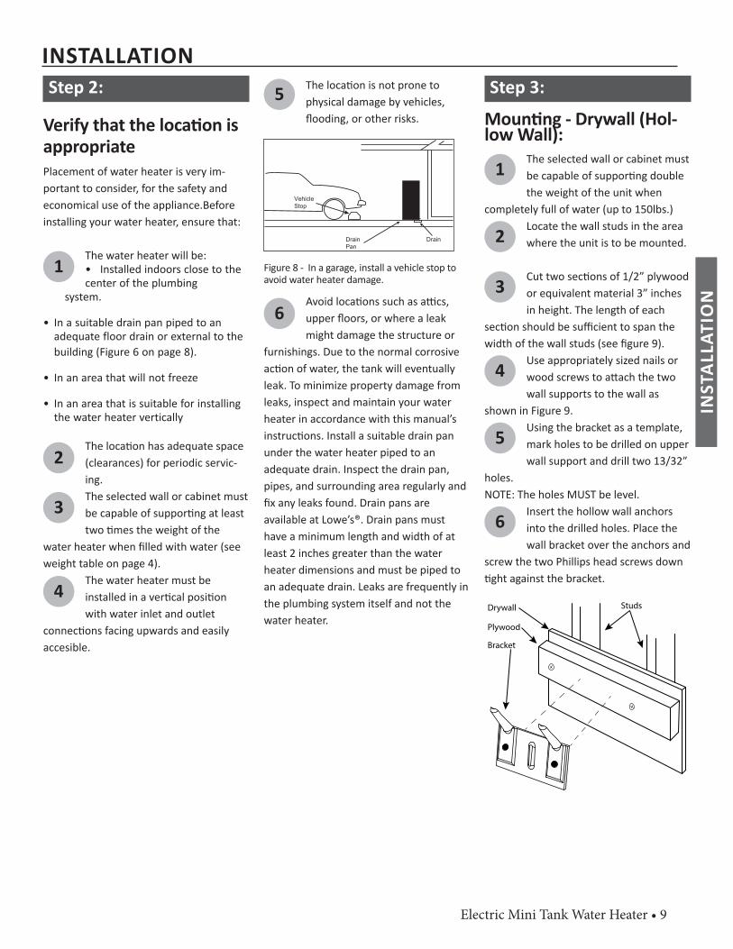
5 The loca on is not prone to physical damage by vehicles, fl ooding, or other risks.
Vehicle Stop
Drain Drain Pan
Figure 8 - In a garage, install a vehicle stop to avoid water heater damage.
6Avoid loca ons such as a cs, upper fl oors, or where a leak might damage the structure or
furnishings. Due to the normal corrosive ac on of water, the tank will eventually leak. To minimize property damage from leaks, inspect and maintain your water heater in accordance with this manual’s instruc ons. Install a suitable drain pan under the water heater piped to an adequate drain. Inspect the drain pan, pipes, and surrounding area regularly and fi x any leaks found. Drain pans are available at Lowe’s®. Drain pans must have a minimum length and width of at least 2 inches greater than the water heater dimensions and must be piped to an adequate drain. Leaks are frequently in the plumbing system itself and not the water heater.
Step 3:
Moun ng - Drywall (Hol-low Wall):
1 The selected wall or cabinet must be capable of suppor ng double the weight of the unit when
completely full of water (up to 150lbs.)
2 Locate the wall studs in the area where the unit is to be mounted.
3 Cut two sec ons of 1/2” plywood or equivalent material 3” inches in height. The length of each
sec on should be suffi cient to span the width of the wall studs (see fi gure 9).
4 Use appropriately sized nails or wood screws to a ach the two wall supports to the wall as
shown in Figure 9.
5 Using the bracket as a template, mark holes to be drilled on upper wall support and drill two 13/32”
holes.NOTE: The holes MUST be level.
6 Insert the hollow wall anchors into the drilled holes. Place the wall bracket over the anchors and
screw the two Phillips head screws down ght against the bracket.
StudsDrywall
Plywood
Bracket
INSTALLATION
INST
ALLA
TIO
N
10 • Electric Mini Tank Water Heater
Figure 9 - Mounting for Drywall
Moun ng - Masonry Wall (Solid Wall):
1 The selected wall or cabinet must be capable of suppor ng double the weight of the unit when
completely full of water (up to 150lbs).
2 The installa on area must provide adequate clearances for removal of the front panel and
servicing the unit.
3 Drill two 13/32” holes in the masonry wall.NOTE: The holes MUST be level
and at least 3-1/2” deep.. 4 Insert the masonry wall anchors
into the drilled holes. Place the wall bracket over the anchors
and screw the two Phillips head screws ght against the bracket.
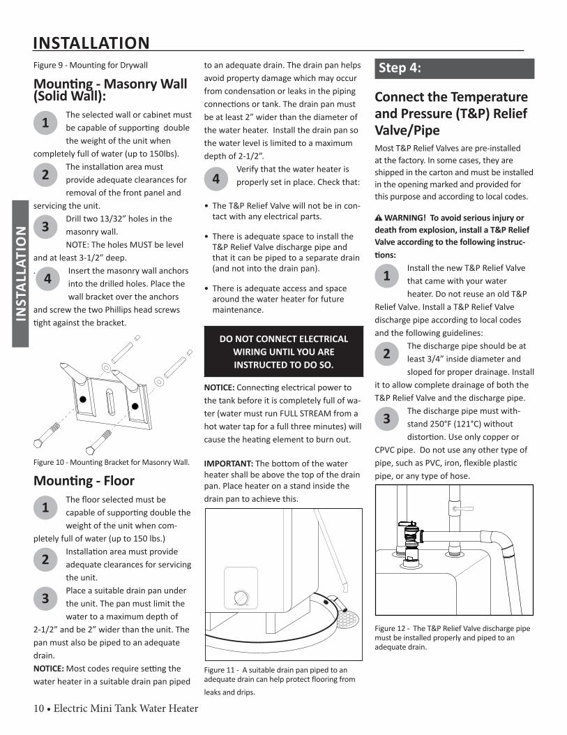
Figure 10 - Mounting Bracket for Masonry Wall.
Moun ng - Floor
1 The fl oor selected must be capable of suppor ng double the weight of the unit when com-
pletely full of water (up to 150 lbs.)
2 Installa on area must provide adequate clearances for servicing the unit.
3 Place a suitable drain pan under the unit. The pan must limit the water to a maximum depth of
2-1/2” and be 2” wider than the unit. The pan must also be piped to an adequate drain.NOTICE: Most codes require se ng the water heater in a suitable drain pan piped
to an adequate drain. The drain pan helps avoid property damage which may occur from condensa on or leaks in the piping connec ons or tank. The drain pan must be at least 2” wider than the diameter of the water heater. Install the drain pan so the water level is limited to a maximum depth of 2-1/2”.
4Verify that the water heater is properly set in place. Check that:
• The T&P Relief Valve will not be in con-tact with any electrical parts.
• There is adequate space to install the T&P Relief Valve discharge pipe and that it can be piped to a separate drain (and not into the drain pan).
• There is adequate access and space around the water heater for future maintenance.
DO NOT CONNECT ELECTRICALWIRING UNTIL YOU AREINSTRUCTED TO DO SO.
NOTICE: Connec ng electrical power to the tank before it is completely full of wa-ter (water must run FULL STREAM from a hot water tap for a full three minutes) will cause the hea ng element to burn out.
IMPORTANT: The bottom of the water heater shall be above the top of the drain pan. Place heater on a stand inside the drain pan to achieve this.
MAX
1
2
125°F
Figure 11 - A suitable drain pan piped to an adequate drain can help protect flooring from leaks and drips.
Step 4:
Connect the Temperature and Pressure (T&P) Relief Valve/PipeMost T&P Relief Valves are pre-installed at the factory. In some cases, they are shipped in the carton and must be installed in the opening marked and provided for this purpose and according to local codes.
WARNING! To avoid serious injury or death from explosion, install a T&P Relief Valve according to the following instruc- ons:
1 Install the new T&P Relief Valve that came with your water heater. Do not reuse an old T&P
Relief Valve. Install a T&P Relief Valve discharge pipe according to local codes and the following guidelines:
2 The discharge pipe should be at least 3/4” inside diameter and sloped for proper drainage. Install
it to allow complete drainage of both the T&P Relief Valve and the discharge pipe.
3 The discharge pipe must with-stand 250°F (121°C) without distor on. Use only copper or
CPVC pipe. Do not use any other type of pipe, such as PVC, iron, fl exible plas c pipe, or any type of hose.
Figure 12 - The T&P Relief Valve discharge pipe must be installed properly and piped to an adequate drain.
INSTALLATIONIN
STAL
LATI
ON
Electric Mini Tank Water Heater • 11
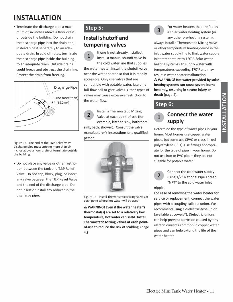
• Terminate the discharge pipe a maxi-mum of six inches above a fl oor drain or outside the building. Do not drain the discharge pipe into the drain pan; instead pipe it separately to an ade-quate drain. In cold climates, terminate the discharge pipe inside the building to an adequate drain. Outside drains could freeze and obstruct the drain line. Protect the drain from freezing.
Discharge Pipe
6 “ (15.2cm)(no more than)
Figure 13 - The end of the T&P Relief Valve discharge pipe must stop no more than six inches above a floor drain or terminate outside the building.
• Do not place any valve or other restric- on between the tank and T&P Relief
Valve. Do not cap, block, plug, or insert any valve between the T&P Relief Valve and the end of the discharge pipe. Do not insert or install any reducer in the discharge pipe.
Step 5:
Install shutoff andtempering valves
1If one is not already installed, install a manual shutoff valve in the cold water line that supplies
the water heater. Install the shutoff valve near the water heater so that it is readily accessible. Only use valves that are compa ble with potable water. Use only full-fl ow ball or gate valves. Other types of valves may cause excessive restric on to the water fl ow.
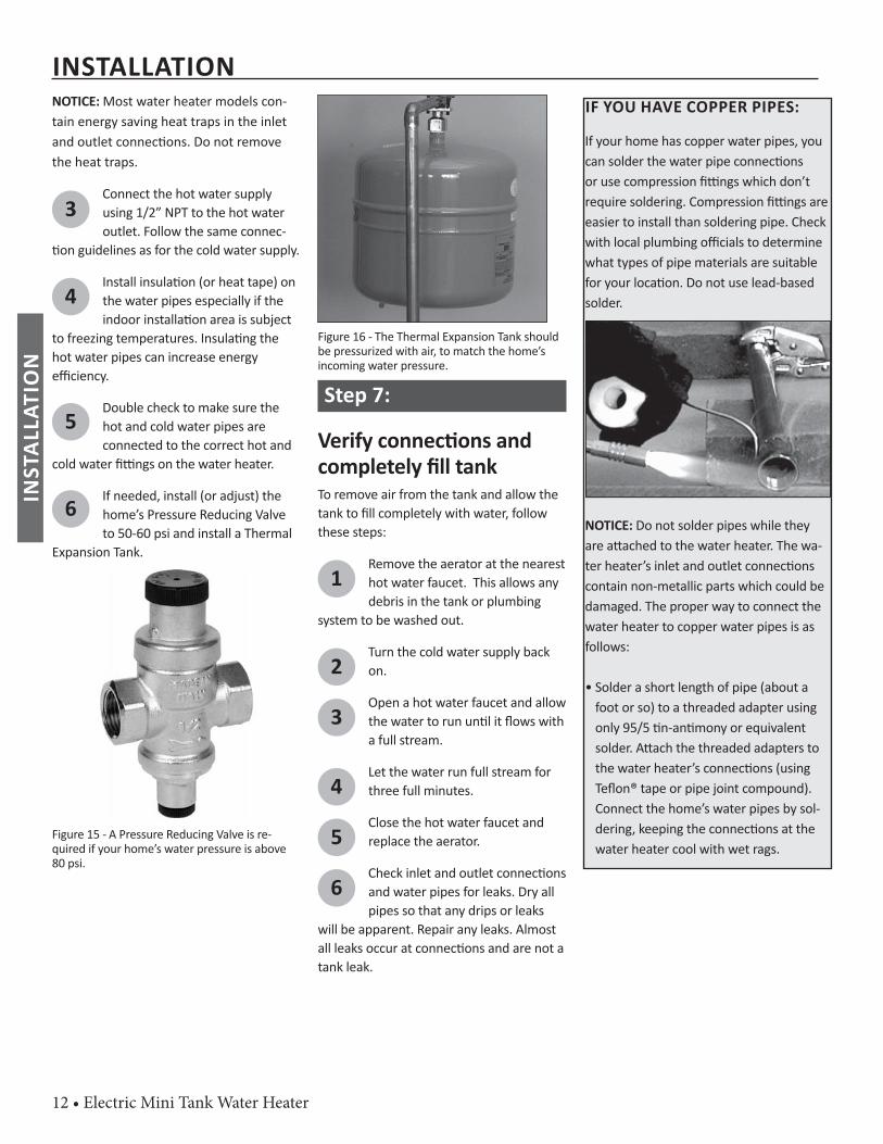
2Install a Thermosta c Mixing Valve at each point-of-use (for example, kitchen sink, bathroom
sink, bath, shower). Consult the valve manufacturer’s instruc ons or a qualifi ed person.
Figure 14 - Install Thermostatic Mixing Valves at each point where hot water will be used.
WARNING! Even if the water heater’s thermostat(s) are set to a rela vely low temperature, hot water can scald. Install Thermosta c Mixing Valves at each point-of-use to reduce the risk of scalding. (page 4.)
3For water heaters that are fed by a solar water hea ng system (or any other pre-hea ng system),
always install a Thermosta c Mixing Valve or other temperature limi ng device in the inlet water supply line to limit water supply inlet temperature to 120°F. Solar water hea ng systems can supply water with temperatures exceeding 170°F and may result in water heater malfunc on.
WARNING! Hot water provided by solar hea ng systems can cause severe burns instantly, resul ng in severe injury or death (page 4).
Step 6:
1 Connect the watersupply
Determine the type of water pipes in your home. Most homes use copper water pipes, but some use CPVC or cross-linked polyethylene (PEX). Use fi ngs appropri-ate for the type of pipe in your home. Do not use iron or PVC pipe – they are not suitable for potable water.
2Connect the cold water supply using 1/2” Na onal Pipe Thread “NPT” to the cold water inlet
nipple. For ease of removing the water heater for service or replacement, connect the water pipes with a coupling called a union. We recommend using a dielectric-type union (available at Lowe’s®). Dielectric unions can help prevent corrosion caused by ny electric currents common in copper water pipes and can help extend the life of the water heater.
INSTALLATION
INST
ALLA
TIO
N
12 • Electric Mini Tank Water Heater
NOTICE: Most water heater models con-tain energy saving heat traps in the inlet and outlet connec ons. Do not remove the heat traps.
3Connect the hot water supply using 1/2” NPT to the hot water outlet. Follow the same connec-
on guidelines as for the cold water supply.
4Install insula on (or heat tape) on the water pipes especially if the indoor installa on area is subject
to freezing temperatures. Insula ng the hot water pipes can increase energy effi ciency.
5Double check to make sure the hot and cold water pipes are connected to the correct hot and
cold water fi ngs on the water heater.
6If needed, install (or adjust) the home’s Pressure Reducing Valve to 50-60 psi and install a Thermal
Expansion Tank.
Figure 15 - A Pressure Reducing Valve is re-quired if your home’s water pressure is above 80 psi.
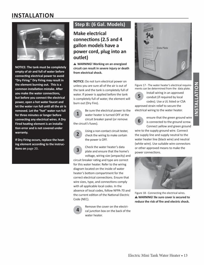
Figure 16 - The Thermal Expansion Tank should be pressurized with air, to match the home’s incoming water pressure.
Step 7:
Verify connec ons and completely fi ll tankTo remove air from the tank and allow the tank to fi ll completely with water, follow these steps:
1Remove the aerator at the nearest hot water faucet. This allows any debris in the tank or plumbing
system to be washed out.
2Turn the cold water supply back on.
3Open a hot water faucet and allow the water to run un l it fl ows with a full stream.
4Let the water run full stream for three full minutes.
5Close the hot water faucet and replace the aerator.
6Check inlet and outlet connec ons and water pipes for leaks. Dry all pipes so that any drips or leaks
will be apparent. Repair any leaks. Almost all leaks occur at connec ons and are not a tank leak.
IF YOU HAVE COPPER PIPES:
If your home has copper water pipes, you can solder the water pipe connec ons or use compression fi ngs which don’t require soldering. Compression fi ngs are easier to install than soldering pipe. Check with local plumbing offi cials to determine what types of pipe materials are suitable for your loca on. Do not use lead-based solder.
NOTICE: Do not solder pipes while they are a ached to the water heater. The wa-ter heater’s inlet and outlet connec ons contain non-metallic parts which could be damaged. The proper way to connect the water heater to copper water pipes is as follows:
• Solder a short length of pipe (about a foot or so) to a threaded adapter using only 95/5 n-an mony or equivalent solder. A ach the threaded adapters to the water heater’s connec ons (using Tefl on® tape or pipe joint compound). Connect the home’s water pipes by sol-dering, keeping the connec ons at the water heater cool with wet rags.
INSTALLATIONIN
STAL
LATI
ON
Electric Mini Tank Water Heater • 13
NOTICE: The tank must be completely empty of air and full of water before connec ng electrical power to avoid “Dry Firing.” Dry Firing may result in the element burning out. This is a common installa on mistake. A er you make the water connec ons, but before you connect the electrical power, open a hot water faucet and let the water run full un l all the air is removed. Let the “hot” water run full for three minutes or longer before connec ng any electrical wires. A Dry Fired hea ng element is an installa- on error and is not covered under
warranty.
If Dry Firing occurs, replace the heat-ing element according to the instruc- ons on page 20.
Step 8: (6 Gal. Models)
Make electricalconnec ons (2.5 and 4 gallon models have a power cord, plug into an outlet)
WARNING! Working on an energized circuit can result in severe injury or death from electrical shock.
NOTICE: Do not turn electrical power on unless you are sure all of the air is out of the tank and the tank is completely full of water. If power is applied before the tank is completely full of water, the element will burn out (Dry Fire).
1Be sure the electrical power to the water heater is turned OFF at the circuit breaker panel (or remove
the circuit’s fuses).
2Using a non-contact circuit tester, check the wiring to make certain the power is OFF.
3Check the water heater’s data plate and ensure that the home’s voltage, wiring size (ampacity) and
circuit breaker ra ng and type are correct for this water heater. Refer to the wiring diagram located on the inside of water heater’s bo om compartment for the correct electrical connec ons. Ensure that wire sizes, type, and connec ons comply with all applicable local codes. In the absence of local codes, follow NFPA-70 and the current edi on of the Na onal Electric Code (NEC).
4Remove the cover on the electri-cal junc on box on the back of the water heater.
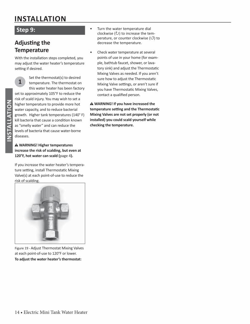
Figure 17 - The water heater’s electrical require-ments can be determined from the data plate.
5Install wiring in an approved conduit (if required by local codes). Use a UL listed or CSA
approved strain relief to secure the electrical wiring to the water heater.
6ensure that the green ground wire is connected to the ground screw. Connect yellow and green ground
wire to the supply ground wire. Connect the supply line and supply neutral to the water heater line (black wire) and neutral (white wire). Use suitable wire connectors or other approved means to make the power connec ons.
Figure 18 - Connecting the electrical wires. WARNING! Be sure cover is secured to
reduce the risk of fi re and electric shock.
INSTALLATION
INST
ALLA
TIO
N
14 • Electric Mini Tank Water Heater
Step 9:
Adjus ng theTemperatureWith the installa on steps completed, you may adjust the water heater’s temperature se ng if desired.
1Set the thermostat(s) to desired temperature. The thermostat on this water heater has been factory
set to approximately 105°F to reduce the risk of scald injury. You may wish to set a higher temperature to provide more hot water capacity, and to reduce bacterial growth. Higher tank temperatures (140° F) kill bacteria that cause a condi on known as “smelly water” and can reduce the levels of bacteria that cause water-borne diseases.
WARNING! Higher temperatures increase the risk of scalding, but even at 120°F, hot water can scald (page 4).
If you increase the water heater’s tempera-ture se ng, install Thermosta c Mixing Valve(s) at each point-of-use to reduce the risk of scalding.
Figure 19 - Adjust Thermostat Mixing Valves at each point-of-use to 120°F or lower.To adjust the water heater’s thermostat:
• Turn the water temperature dial clockwise () to increase the tem-perature, or counter clockwise () to decrease the temperature.
• Check water temperature at several points of use in your home (for exam-ple, bathtub faucet, shower, or lava-tory sink) and adjust the Thermosta c Mixing Valves as needed. If you aren’t sure how to adjust the Thermosta c Mixing Valve se ngs, or aren’t sure if you have Thermosta c Mixing Valves, contact a qualifi ed person.
WARNING! If you have increased the temperature se ng and the Thermosta c Mixing Valves are not set properly (or not installed) you could scald yourself while checking the temperature.
INSTALLATIONIN
STAL
LATI
ON
Electric Mini Tank Water Heater • 15
Step 10: Opera onThe water heater is now ready for normal opera on. To keep your water heater working safely and effi ciently and extend its life, perform maintenance according to the schedule on page 19.
Vaca onTo save energy, lower the temperature se ng on the thermostat(s) if you plan to be gone for an extended me. Follow the instruc ons in Step 9 for adjus ng the thermostat to a lower temperature se ng before you leave and to properly raise the temperature se ng when you return.
C AUTION! Hydrogen gas builds up in a hot water system when it is not used for a long period (two weeks or more). Hydrogen gas is extremely fl ammable. If the hot water system has not been used for two weeks or more, open a hot water faucet for several minutes at the kitchen sink before using any electrical appliances connected to the hot water system. Do not smoke or have an open fl ame or other igni on source near the faucet while it is open.
Need Assistance?
Call our Technical Assistance Hotline at 1-877-817-6750.We can help you with installa on, opera on, troubleshoo ng, or maintenance.
Before you call, write down the model and serial number from thewater heater’s data plate.
INSTALLATION
INST
ALLA
TIO
N
16 • Electric Mini Tank Water Heater
WARNING! Working near an energized circuit can result in severe injury or death from electrical shock.
WARNING! When you are fi nished, be sure all covers are secured to reduce the risk of fi re and electric shock.
No Hot WaterThe most likely reasons for an electric water heater to produce NO hot water are:
• No electric power—a common problem with new installations
• Burned out element (Dry Fired) — a common problem with new installa-tions
• The water heater’s inlet and outlet con-nections are reversed (usually only in new installations)
• Broken thermostat (or wiring)
• A leak in the hot water side of the plumb-ing system that exceeds the water heat-er’s heating capacity and makes it appear that the water heater is producing little to no hot water
Follow these steps to diagnose and cor-rect common electrical problems:
1Check the electric power to the water heater. No hot water is o en caused by a problem with
the home’s electrical wiring or circuit breakers. You’ll need a non-contact circuit tester. For six (6) gallon water heaters, follow these guidelines:
• Locate the water heater’s circuit break-er and turn it off (or remove the cir-cuit’s fuses).
• Drain the water heater (see “Drain the Water Heater” section).
• Locate the electrical junction box on the botton of the water heater and remove the cover.
• Identify the two power wires. The power wires are usually black/white or black/red—the green or copper wire is the ground wire.
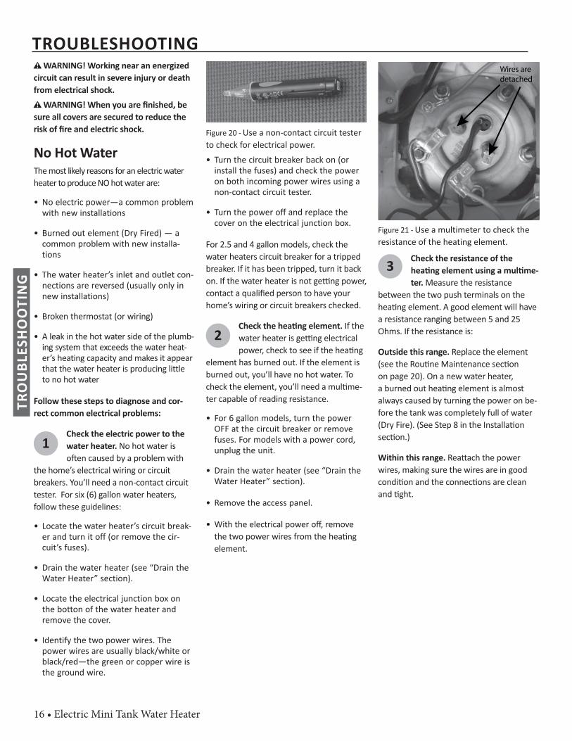
Figure 20 - Use a non-contact circuit tester to check for electrical power.• Turn the circuit breaker back on (or
install the fuses) and check the power on both incoming power wires using a non-contact circuit tester.
• Turn the power off and replace the cover on the electrical junction box.
For 2.5 and 4 gallon models, check the water heaters circuit breaker for a tripped breaker. If it has been tripped, turn it back on. If the water heater is not ge ng power, contact a qualifi ed person to have your home’s wiring or circuit breakers checked.
2Check the hea ng element. If the water heater is ge ng electrical power, check to see if the hea ng
element has burned out. If the element is burned out, you’ll have no hot water. To check the element, you’ll need a mul me-ter capable of reading resistance.
• For 6 gallon models, turn the power OFF at the circuit breaker or remove fuses. For models with a power cord, unplug the unit.
• Drain the water heater (see “Drain the Water Heater” section).
• Remove the access panel.
• With the electrical power off , remove the two power wires from the hea ng element.
Wires are detached
Figure 21 - Use a multimeter to check the resistance of the heating element.
3 Check the resistance of the hea ng element using a mul me-ter. Measure the resistance
between the two push terminals on the hea ng element. A good element will have a resistance ranging between 5 and 25 Ohms. If the resistance is:
Outside this range. Replace the element (see the Rou ne Maintenance sec on on page 20). On a new water heater, a burned out hea ng element is almost always caused by turning the power on be-fore the tank was completely full of water (Dry Fire). (See Step 8 in the Installa on sec on.)
Within this range. Rea ach the power wires, making sure the wires are in good condi on and the connec ons are clean and ght.
TROUBLESHOOTINGTR
OU
BLES
HO
OTI
NG
Electric Mini Tank Water Heater • 17
Insuffi cient Hot Water or Slow Hot WaterRecovery
WARNING! Be sure all covers are secured to reduce the risk of fi re and electric shock.
WARNING! Because of the increased risk from scalding, if you set the water heater’s thermostat(s) higher than 120°F, Thermo-sta c Mixing Valves at each point-of-use are par cularly important (page 4).
If the hot water is simply not warm enough, there are several possible causes:• Faulty Thermostatic Mixing Valve in a faucet
or shower control (check other faucets in the house for hot water)
• Thermostat set too low• Water heater’s capacity too small (or usage
too high)• Reversed plumbing connections or melted
dip tube (usually found soon after new installation)
• Plumbing leak• Bad element• Low supply voltageThermosta c Mixing Valves. If the hot water is simply not warm enough, make sure the faucet you are checking doesn’t have a defec- ve Thermosta c Mixing Valve. Many shower
controls now have built-in mixing valves. If these devices fail, they can reduce the amount of hot water the shower or faucet delivers even though there is plenty of hot water in the tank. Always check the water temperature at several faucets to make sure the problem is not in a faucet or shower control. Thermostats set too low. If the water tem-perature is too cool, adjust the thermostat by turning dial clockwise for a higher tempera-ture.
Undersized water heater. If your water heater runs out of hot water too quickly, it may be too small for your needs. If the water heater is old, consider replacing it with a larger model. If the water heater is in good condi on, you may be able to meet your family’s hot water needs with the exis ng water heater by installing Thermosta c Mixing Valves at each point-of-use and then turning the thermostat(s) to a higher se ng. See “Step 10” on page 14.You can also reduce your home’s hot water needs by washing clothes in cold water, install-ing fl ow restrictors on shower heads, repairing leaky faucets, and taking other conserva on steps. Reversed connec ons. Check the hot and cold connec ons and make sure your home’s hot water pipe is connected to the hot water outlet on the water heater. Usually, reversed connec ons are found soon a er the installa- on of a new unit.
Plumbing leak. Even a small leak in the hot water side of the home’s plumbing system can make it appear that the water heater is producing li le to no hot water. Locate and repair the leak.
TROUBLESHOOTING
TRO
UBL
ESH
OO
TIN
G

18 • Electric Mini Tank Water Heater
Temperature Too HighIf the water temperature is too hot:
• Install or adjust the Thermostatic Mix-ing Valves for each point-of-use (see manufacturer’s instructions), or
• Adjust the temperature by turning the dial counter-clockwise.
A nonfunc oning thermostat or a shorted hea ng element can cause extremely hot water. If the Temperature and Pressure Relief Valve (T&P Valve) releases large amounts of very hot water, it is likely due to a shorted hea ng element, or more rarely a nonfunc oning thermostat.
Low Water PressureCheck both the cold and hot water at a sink to determine if the lower pressure is only on the hot water side. If both hot and cold fau-cets have low pressure, call your local water u lity. If the low pressure is only on the hot water side, the primary causes of this are:
• Partially closed supply valve. Open the water heater’s supply valve fully.
Drips from T&P Relief Valve Discharge PipeA small amount of water dripping from the Temperature and Pressure (T&P) Relief Valve usually means the home’s water pressure is too high or you need a properly sized and pressurized Thermal Expansion Tank. Refer to Step 1 in the Installa on sec- on of this manual for more informa on.
A large amount of hot water coming from the T&P discharge pipe may be due to the tank overhea ng.
WARNING! Do not cap or plug the T&P relief valve or discharge pipe, and do not operate the water heater without a func- oning T&P Relief Valve - this could cause
an explosion.
Water pressure too high. High water pres-sure can cause the T&P Relief Valve to drip. Install a Pressure Reducing Valve (PRV) on the main cold water supply line. Adjust the PRV to between 50 and 60 psi.
Thermal Expansion Tank. Install a Thermal Expansion Tank. If a Thermal Expansion Tank is already installed and the T&P Relief Valve discharge pipe drips, the Thermal Expansion Tank may be pressurized to the wrong pressure or the internal bladder may be defec ve. Refer to the instruc ons that came with the Thermal Expansion Tank for more informa on.
Debris. In rare cases, debris can s ck inside the T&P Relief Valve preven ng the valve from sea ng fully. In that case, the T&P Relief Valve discharge pipe will drip. You may be able to clear debris from the T&P Relief Valve by manually opera ng the valve, allowing small quan es of water to fl ush out the debris. See the label on the T&P Relief Valve for instruc ons.
If the water pressure is between 50 and 60 psi, a Thermal Expansion Tank is installed and properly pressurized, and the valve has been cleared of any debris, and it s ll drips, the valve may be broken—have a qualifi ed person replace the T&P relief valve.
Water OdorHarmless bacteria normally present in tap water can mul ply in water heaters and give off a “ro en egg” smell. Although elimina ng the bacteria that causes “smelly water” with a Chlorina on system the only sure treatment is increasing the water temperature.
In cases where the “ro en egg” smell is pronounced, you can raise the tank temperature to “MAX” in order to reduce bacteria growth in the tank.
WARNING! Because higher tempera-tures increase the risk of scalding, if you set the thermostat(s) higher than 120°F, Thermosta c Mixing Valves at each point-of-use are par cularly important (page 4).
NOTE: To protect the tank, an anode rod must be installed in the water heater at all mes or the warranty is void.
TROUBLESHOOTINGTR
OU
BLES
HO
OTI
NG
Electric Mini Tank Water Heater • 19
Rou ne Maintenance Rou ne maintenance will help your water heater last longer and work be er. If you can’t perform these rou ne maintenance tasks yourself, contact a qualifi ed person.
A er the fi rst six months, drain and fl ush the water heater and inspect the anode rod. Depending on the hardness of your water, repeat this process at least annually, or more frequently if needed. From me to me, you may need to replace a hea ng element or a thermostat. All three mainte-nance tasks are described below.
Draining and Flushing theWater HeaterTap water contains minerals that can form lime deposits on hea ng elements or sediment in the bo om of the tank. The amount of lime deposits or sediment depends on the hardness of your tap water. The rate at which sediment builds up depends on water quality and hardness in your area, the temperature se ngs, and other variables. We recommend draining and fl ushing the water heater a er the fi rst six months of opera on to determine the amount of sediment build up. Draining sed-iment extends the life of the tank, hea ng elements, and drain valves.
• In areas with very hard water, remove and check the heating element when-ever you drain the tank. If you have heavy lime deposits on heating ele-ment, you will need to replace it more often.
• Sediment may form large masses that can prevent the tank from draining. Have a qualified person use a de-liming agent suitable for potable water to remove the sediment buildup.
• In most cases, it is easier and cheaper to replace lime-encrusted elements than trying to remove heavy lime deposits.
To drain and fl ush the tank:
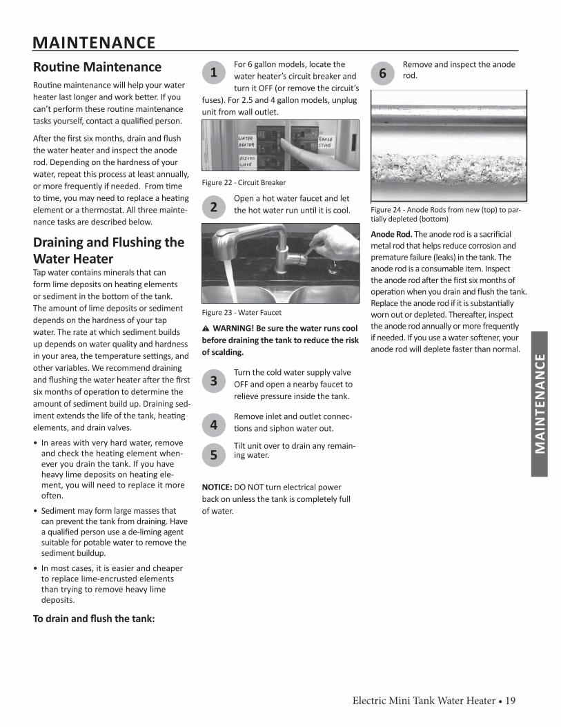
1For 6 gallon models, locate the water heater’s circuit breaker and turn it OFF (or remove the circuit’s
fuses). For 2.5 and 4 gallon models, unplug unit from wall outlet.
Figure 22 - Circuit Breaker
2Open a hot water faucet and let the hot water run un l it is cool.
Figure 23 - Water Faucet
WARNING! Be sure the water runs cool before draining the tank to reduce the risk of scalding.
3Turn the cold water supply valve OFF and open a nearby faucet to relieve pressure inside the tank.
4Remove inlet and outlet connec- ons and siphon water out.
5Tilt unit over to drain any remain-ing water.
NOTICE: DO NOT turn electrical power back on unless the tank is completely full of water.
6Remove and inspect the anode rod.
Figure 24 - Anode Rods from new (top) to par-tially depleted (bottom)
Anode Rod. The anode rod is a sacrifi cial metal rod that helps reduce corrosion and premature failure (leaks) in the tank. The anode rod is a consumable item. Inspect the anode rod a er the fi rst six months of opera on when you drain and fl ush the tank. Replace the anode rod if it is substan ally worn out or depleted. Therea er, inspect the anode rod annually or more frequently if needed. If you use a water so ener, your anode rod will deplete faster than normal.
MAINTENANCE
MAI
NTE
NAN
CE
20 • Electric Mini Tank Water Heater
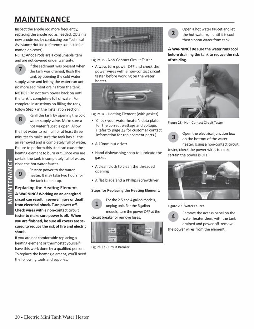
Inspect the anode rod more frequently, replacing the anode rod as needed. Obtain a new anode rod by contac ng our Technical Assistance Hotline (reference contact infor-ma on on cover). NOTE: Anode rods are a consumable item and are not covered under warranty.
7 If the sediment was present when the tank was drained, fl ush the tank by opening the cold water
supply valve and le ng the water run un l no more sediment drains from the tank. NOTICE: Do not turn power back on un l the tank is completely full of water. For complete instruc ons on fi lling the tank, follow Step 7 in the Installa on sec on.
8Refi ll the tank by opening the cold water supply valve. Make sure a hot water faucet is open. Allow
the hot water to run full for at least three minutes to make sure the tank has all the air removed and is completely full of water. Failure to perform this step can cause the hea ng element to burn out. Once you are certain the tank is completely full of water, close the hot water faucet.
9Restore power to the water heater. It may take two hours for the tank to heat up.
Replacing the Hea ng Element WARNING! Working on an energized
circuit can result in severe injury or death from electrical shock. Turn power off . Check wires with a non-contact circuit tester to make sure power is off . When you are fi nished, be sure all covers are se-cured to reduce the risk of fi re and electric shock. If you are not comfortable replacing a hea ng element or thermostat yourself, have this work done by a qualifi ed person. To replace the hea ng element, you’ll need the following tools and supplies:
Figure 25 - Non-Contact Circuit Tester• Always turn power OFF and check the
power wires with a non-contact circuit tester before working on the water heater.
Figure 26 - Heating Element (with gasket)• Check your water heater’s data plate
for the correct wattage and voltage. (Refer to page 22 for customer contact information for replacement parts.)
• A 10mm nut driver.
• Hand dishwashing soap to lubricate the gasket
• A clean cloth to clean the threaded opening
• A flat blade and a Phillips screwdriver
Steps for Replacing the Hea ng Element:
1For the 2.5 and 4 gallon models, unplug unit. For the 6 gallon models, turn the power OFF at the
circuit breaker or remove fuses.
Figure 27 - Circuit Breaker
2Open a hot water faucet and let the hot water run un l it is cool then siphon water from tank.
WARNING! Be sure the water runs cool before draining the tank to reduce the risk of scalding.
Figure 28 - Non-Contact Circuit Tester
3Open the electrical junc on box on the bo om of the water heater. Using a non-contact circuit
tester, check the power wires to make certain the power is OFF.
Figure 29 - Water Faucet
4 Remove the access panel on the water heater then, with the tank drained and power off , remove
the power wires from the element.
MAINTENANCEM
AIN
TEN
ANCE
Electric Mini Tank Water Heater • 21
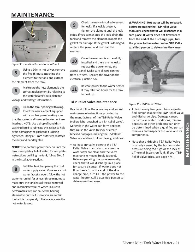
Junction Box
Access Panel
Figure 30 - Junction Box and Access Panel
5Using a 10mm nut driver, remove the fi ve (5) nuts a aching the element to the tank and extract
the element from the tank.
6Make sure the new element is the correct replacement by referring to the water heater’s data plate for
voltage and wa age informa on.
7 Clean the tank opening with a rag. Insert the new element equipped with a rubber gasket making sure
that the gasket and holes in the element are lined up.. NOTE: Use a drop of hand dish-washing liquid to lubricate the gasket to help avoid damaging the gasket as it is being ghtened. Using a 10mm nutdriver, rea ach
the nuts and hand ghten.
NOTICE: Do not turn power back on un l the tank is completely full of water. For complete instruc ons on fi lling the tank, follow Step 7 in the Installa on sec on.
8Refi ll the tank by opening the cold water supply valve. Make sure a hot water faucet is open. Allow the hot
water to run full for at least three minutes to make sure the tank has all the air removed and is completely full of water. Failure to perform this step can cause the hea ng element to burn out. Once you are certain the tank is completely full of water, close the hot water faucet.
9Check the newly installed element for leaks. If a leak is present, ghten the element un l the leak
stops. If you cannot stop the leak, drain the tank and remove the element. Inspect the gasket for damage. If the gasket is damaged, replace the gasket and re-install the element.
10Once the element is successfully installed and there are no leaks, replace the power wires, and
access panel. Make sure all wire connec- ons are ght. Replace the cover on the
electrical junc on box.
11Restore power to the water heater. It may take two hours for the tank to heat up.
T&P Relief Valve Maintenance
Read and follow the opera ng and annual maintenance instruc ons provided by the manufacturer of the T&P Relief Valve (yellow label a ached to T&P Relief Valve). Minerals in the water can form deposits that cause the valve to s ck or create blocked passages, making the T&P Relief Valve inopera ve. Follow these guidelines:
• At least annually, operate the T&P Relief Valve manually to ensure the waterways are clear and the valve mechanism moves freely (above). Before operating the valve manually, check that it will discharge in a place for secure disposal. If water does not flow freely from the end of the dis-charge pipe, turn OFF the power to the water heater. Call a qualified person to determine the cause.
WARNING! Hot water will be released. Before opera ng the T&P relief valve manually, check that it will discharge in a safe place. If water does not fl ow freely from the end of the discharge pipe, turn the power to the water heater OFF. Call a qualifi ed person to determine the cause.
Figure 31 - T&P Relief Valve• At least every five years, have a quali-
fied person inspect the T&P Relief Valve and discharge pipe. Damage caused by corrosive water conditions, mineral deposits, or other problems can only be determined when a qualified person removes and inspects the valve and its components.
• Note that a dripping T&P Relief Valve is usually caused by the home’s water pressure being too high or the lack of a Thermal Expansion Tank. If your T&P Relief Valve drips, see page <?>.
MAINTENANCE
MAI
NTE
NAN
CE
22 • Electric Mini Tank Water Heater
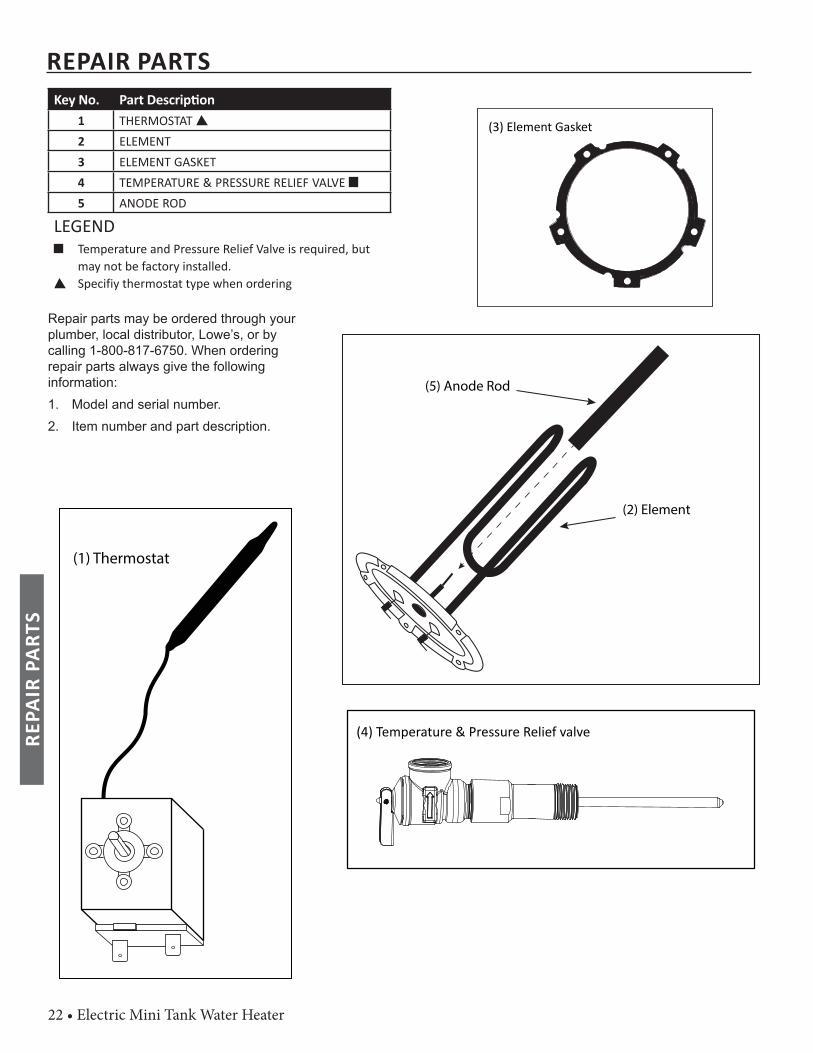
Key No. Part Descrip on1 THERMOSTAT 2 ELEMENT3 ELEMENT GASKET4 TEMPERATURE & PRESSURE RELIEF VALVE 5 ANODE ROD
LEGEND Temperature and Pressure Relief Valve is required, but
may not be factory installed. Specifiy thermostat type when ordering
Repair parts may be ordered through your plumber, local distributor, Lowe’s, or by calling 1-800-817-6750. When ordering repair parts always give the following information:1. Model and serial number. 2. Item number and part description.
REPAIR PARTS
(5) Anode Rod
(2) Element
(4) Temperature & Pressure Relief valve
(3) Element Gasket
(1) Thermostat
REPA
IR P
ARTS
Electric Mini Tank Water Heater • 23
WIRE DIAGRAM
WIR
E D
IAG
RAM
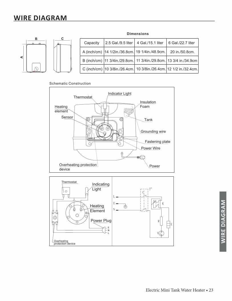
2.5 Gal./9.5 liter 4 Gal./15.1 liter 6 Gal./22.7 literCapacity
A (inch/cm)
B (inch/cm)
C (inch/cm)
14 1/2in./36.8cm. 19 1/4in./48.9cm. 20 in./50.8cm.
11 3/4in./29.8cm. 11 3/4in./29.8cm. 13 3/4 in./34.9cm
10 3/8in./26.4cm. 10 3/8in./26.4cm. 12 1/2 in./32.4cm.

®Tefl on is a registered trademark of E.I. Du Pont De Nemours and Company LOWE’S is a registered trademark of LF, LLC.Limited Warranty provided by Manufacturer.
Related Documents