Hindawi Publishing Corporation International Journal of Antennas and Propagation Volume 2013, Article ID 548610, 5 pages http://dx.doi.org/10.1155/2013/548610 Research Article Simplified Printed Log-Periodic Dipole Array Antenna Fed by CBCPW Guohua Zhai, 1 Yong Cheng, 2 Qiuyan Yin, 1 Shouzheng Zhu, 1 and Jianjun Gao 1 1 School of Information and Science Technology, East China Normal University, Shanghai 200241, China 2 Shanghai Normal University, Tianhua College, Shanghai 201815, China Correspondence should be addressed to Guohua Zhai; [email protected] Received 29 August 2013; Accepted 3 September 2013 Academic Editor: Xiao Ping Chen Copyright © 2013 Guohua Zhai et al. is is an open access article distributed under the Creative Commons Attribution License, which permits unrestricted use, distribution, and reproduction in any medium, provided the original work is properly cited. A novel simple approach for designing single-layer printed log-periodic dipole array (PLPDA) antenna fed by conductor-backed coplanar waveguide (CBCPW) is presented. e PLPDA antenna has the merits of wide bandwidth, low profile, and stable radiation pattern, which should be fed by the balanced line. e balanced line, created by the geometric features of the CBCPW, provides a balun with a considerably wide bandwidth with low profile, broad bandwidth, low insertion loss, and so forth. e prototype of the proposed CBCPW-fed printed log-periodic array at Ka band is designed and fabricated; the measured data are in good agreement with the simulated results. 1. Introduction As an end-fire type antenna, the log-periodic dipole array (LPDA) antenna has the merits of fixed peak radiation and stable radiation pattern within the operating frequency, so it is one of the candidates for the modern wireless communi- cations system. Numerous studies have been documented on the design method and the performance of the conventional LPDA antenna since the 1960s [1–7]. In order to achieve low profile, printed log-periodic dipole arrays (PLPDA) antenna was proposed based on the printed integrated board (PCB) technology [8–14]. Practi- cally, the performance of the PLPDA antenna is determined by the feeding network. At an early stage, the PLPDA antenna was designed on a piece of the double-layer printed circuit board [8–11], but it increases the fabrication cost and limits the productivity. en, the fabrication cost is reduced by using single-layer printed circuit, so the single-layer PLPDA antennas with two coaxial cables as the feeding network were proposed [12, 13]. However, soldering coaxial cables bring significant fabrication error and misalignment, especially at millimeter-wave frequencies. A single-layer slot PLPDA antenna fed by coplanar waveguide (CPW) was proposed [14], the CPW transmission line has been widely used in the monolithic millimeter-wave integrated circuits (MMIC), but this transmission line suffers from high insertion loss in the transition, radiation loss, serious crosstalk, and lower power handling capability because of its open structure. Recently, the substrate integrated circuits (SIC) concept, in particular substrate integrated waveguide (SIW) tech- nique, has been demonstrated as a promising scheme for low-cost, small size, relatively high power, low radiation loss, and high-density integrated microwave and millimeter-wave components and systems, which has been widely used in the low profile antenna design [15–18]. And the substrate integrated PLPDA antenna is proposed [19]. However, this new feeding network is larger, especially at lower frequency. And the printed dipoles of the PLPDA antenna mentioned above are all cross-symmetrically spaced along the parallel feed lines on both sides of the dielectric substrate. So, it necessitates two sides of the substrate to be etched. In this paper, a simplified PLPDA antenna fed by CBCPW is presented, which can be called CBCPW PLPDA antenna. e geometry of the proposed antenna is shown in Figure 1. It has advantages of low profile, broadband, light weight, and ease of integration to the planar circuits. e entire structure is fabricated on a piece of PCB. And all the printed dipoles and

Welcome message from author
This document is posted to help you gain knowledge. Please leave a comment to let me know what you think about it! Share it to your friends and learn new things together.
Transcript
Hindawi Publishing CorporationInternational Journal of Antennas and PropagationVolume 2013, Article ID 548610, 5 pageshttp://dx.doi.org/10.1155/2013/548610
Research ArticleSimplified Printed Log-Periodic Dipole Array AntennaFed by CBCPW
Guohua Zhai,1 Yong Cheng,2 Qiuyan Yin,1 Shouzheng Zhu,1 and Jianjun Gao1
1 School of Information and Science Technology, East China Normal University, Shanghai 200241, China2 Shanghai Normal University, Tianhua College, Shanghai 201815, China
Correspondence should be addressed to Guohua Zhai; [email protected]
Received 29 August 2013; Accepted 3 September 2013
Academic Editor: Xiao Ping Chen
Copyright © 2013 Guohua Zhai et al. This is an open access article distributed under the Creative Commons Attribution License,which permits unrestricted use, distribution, and reproduction in any medium, provided the original work is properly cited.
A novel simple approach for designing single-layer printed log-periodic dipole array (PLPDA) antenna fed by conductor-backedcoplanar waveguide (CBCPW) is presented.The PLPDA antenna has themerits of wide bandwidth, low profile, and stable radiationpattern, which should be fed by the balanced line. The balanced line, created by the geometric features of the CBCPW, provides abalun with a considerably wide bandwidth with low profile, broad bandwidth, low insertion loss, and so forth.The prototype of theproposed CBCPW-fed printed log-periodic array at Ka band is designed and fabricated; the measured data are in good agreementwith the simulated results.
1. Introduction
As an end-fire type antenna, the log-periodic dipole array(LPDA) antenna has the merits of fixed peak radiation andstable radiation pattern within the operating frequency, so itis one of the candidates for the modern wireless communi-cations system. Numerous studies have been documented onthe design method and the performance of the conventionalLPDA antenna since the 1960s [1–7].
In order to achieve low profile, printed log-periodicdipole arrays (PLPDA) antenna was proposed based on theprinted integrated board (PCB) technology [8–14]. Practi-cally, the performance of the PLPDA antenna is determinedby the feeding network. At an early stage, the PLPDA antennawas designed on a piece of the double-layer printed circuitboard [8–11], but it increases the fabrication cost and limitsthe productivity. Then, the fabrication cost is reduced byusing single-layer printed circuit, so the single-layer PLPDAantennas with two coaxial cables as the feeding network wereproposed [12, 13]. However, soldering coaxial cables bringsignificant fabrication error and misalignment, especiallyat millimeter-wave frequencies. A single-layer slot PLPDAantenna fed by coplanar waveguide (CPW) was proposed[14], the CPW transmission line has been widely used in
the monolithic millimeter-wave integrated circuits (MMIC),but this transmission line suffers from high insertion lossin the transition, radiation loss, serious crosstalk, and lowerpower handling capability because of its open structure.
Recently, the substrate integrated circuits (SIC) concept,in particular substrate integrated waveguide (SIW) tech-nique, has been demonstrated as a promising scheme forlow-cost, small size, relatively high power, low radiation loss,and high-density integrated microwave and millimeter-wavecomponents and systems, which has been widely used inthe low profile antenna design [15–18]. And the substrateintegrated PLPDA antenna is proposed [19]. However, thisnew feeding network is larger, especially at lower frequency.And the printed dipoles of the PLPDA antenna mentionedabove are all cross-symmetrically spaced along the parallelfeed lines on both sides of the dielectric substrate. So, itnecessitates two sides of the substrate to be etched.
In this paper, a simplified PLPDAantenna fed byCBCPWis presented, which can be called CBCPW PLPDA antenna.The geometry of the proposed antenna is shown in Figure 1.It has advantages of low profile, broadband, light weight, andease of integration to the planar circuits. The entire structureis fabricated on a piece of PCB.And all the printed dipoles and

2 International Journal of Antennas and Propagation
L
W4
W3
W2
W1
L4
L3
L2
L1
S4
S3
S2
S1
d2d1
Wg
a1 a2
Wsef
Wsef
(a) Top layer
drdv
(b) Bottom layer
Figure 1: Geometry of the proposed CBCPW PLPDA antenna.
the feed lines of the PLPDA antenna are printed on only oneside of the dielectric substrate. Therefore, this novel antennaalleviates the deign complexity, reduces the cost, and can beeasy to integrate with MMIC.
2. CBCPW PLPDA Antenna Design
For the proposed antenna design, the 50ΩCBCPWis directlytransited to the two parallel transmission strip lines, alongwhich the dipole elements are symmetrically distributed onthe top metallic layer of the substrate. One parallel line isconnected to the central line of the CBCPW, and the otherone is connected to one side of the ground on the top sideof the CBCPW.The bottom ground of the CBCPW is etchedon the bottom layer of the substrate; the top and the bottommetallic layers of the CBCPW are connected by the metallicvias to balance the transmission line.
Figure 2 depicts the dominant mode in the cross-sectionof the CBCPW, which clearly shows the 180∘ phase differencebetween the central line and the ground of the CBCPW.Therefore, the structure of CBCPW can provide a goodperformance over a fairly wide bandwidth and perform agood balun line for the feeding network of the single-layerPLPDA antenna.
The electromagnetic power excited by the feeder istransmitted from CBCPW to the dipole elements along the
Figure 2: Simulated electric field distribution of the dominantmodein the cross-section of the CBCPW.
two parallel transmission strips line, which is shown inFigure 3. And the parallel transmission strip lines acts as atransformer between the CBCPW and the PLPDA antenna;it also performs as the balun. Therefore, the currents of thedipole elements on the left side are in phasewith those printedin the opposite direction on the right side of the substrate,which results in mono-directional radiation towards theshorter elements.
The parameters of the proposed antenna are determinedby the modified Carrel method [2], including an effectiverelative dielectric permittivity in computations to dipolelengths and spacing. According to the principle of the PLPDAantenna, the optimumvalues of the parameters𝐿
𝑛, 𝑆𝑛, and𝑊
𝑛

International Journal of Antennas and Propagation 3
Figure 3: Simulated electric field density distributions of theproposed antenna (35GHz).
can be determined by the scale factor 𝜏 and spacing factor 𝜎as given by [7, 8]
𝜏 =𝐿(𝑛+1)
𝐿𝑛
=𝑊𝑛+1
𝑊𝑛
, (1)
𝜎 =1 − 𝜏
4 ∗ tan𝛼=𝑆𝑛
4 ∗ 𝐿𝑛
. (2)
The value of the structure bandwidth 𝐵𝑠= 𝐵×𝐵ar, where 𝐵 is
the desired bandwidth ratio and 𝐵ar is the bandwidth for theactive region given by [7, 8]
𝐵ar = 1.1 + 7.7(1 − 𝜏)2cot𝛼. (3)
The number of the dipole elements𝑁 is obtained from [7, 8]
𝑁 = 1 +log𝐵𝑠
log (1/𝜏). (4)
The actual half-length of the largest dipole element adjacentto the feed point is given by [7, 8]
𝐿1=𝜆eff min2=𝑐
2𝑓max√𝜀eff,
𝜀eff =𝜀𝑟+ 1
2+𝜀𝑟+ 1
2
1
√1 + 12ℎ/𝑊1
,
(5)
where 𝜆eff min is the shortest effective working wavelength,𝜀eff is the effective dielectric permittivity, 𝜀
𝑟is the dielectric
constant, ℎ is the substrate thickness, and𝑊1is the width of
the first dipole element.Hence, the parameters of this structure to be tuned
are 𝜏, 𝜎, 𝑊1, 𝑆1, and 𝑊sef, which can be optimized to
further enhance the performance. In this paper, the proposedCBCPW PLPDA antenna is designed at 25–40GHz, which isprinted on one side of a 0.5mm thick FR-4 substrate with thepermittivity of 4.3. The size parameters of the 50Ω CBCPWcan be first decided, and then the length of the longest dipole𝐿1can be calculated from (5). Then, the length of the other
elements can be calculated from (1); meanwhile, the width of
Table 1: Dimensions of CBCPW PLPDA antenna.
Symbol Quantity𝑊1
1𝑊4
0.2𝐿3
4.3𝑆2
1𝑊sef 0.5𝑑1
1𝑎2
2𝑊2
0.2𝐿1
7𝐿4
3.2𝑆3
1𝑊𝑔
0.15𝑑2
1𝑑𝑟
0.25𝑊3
0.2𝐿2
5𝑆1
1.2𝑆4
0.6ℎ 0.5𝑎1
2𝑑V 0.8Unit: mm.
the longest dipole𝑊1, the feed line𝑊sef, and the distance from
the feed point to the first dipole 𝑆1can be optimized by the
full-wave simulation software HFSS. The width of the otherelements𝑊
𝑛and the spacing between the elements 𝑆
𝑛can be
obtained from (1) and (2). After optimization with the full-wave simulation software HFSS, the dipole element 𝑁 is 4,and the other geometry parameters of the proposed antennaare shown in Table 1.
3. Experimental Results
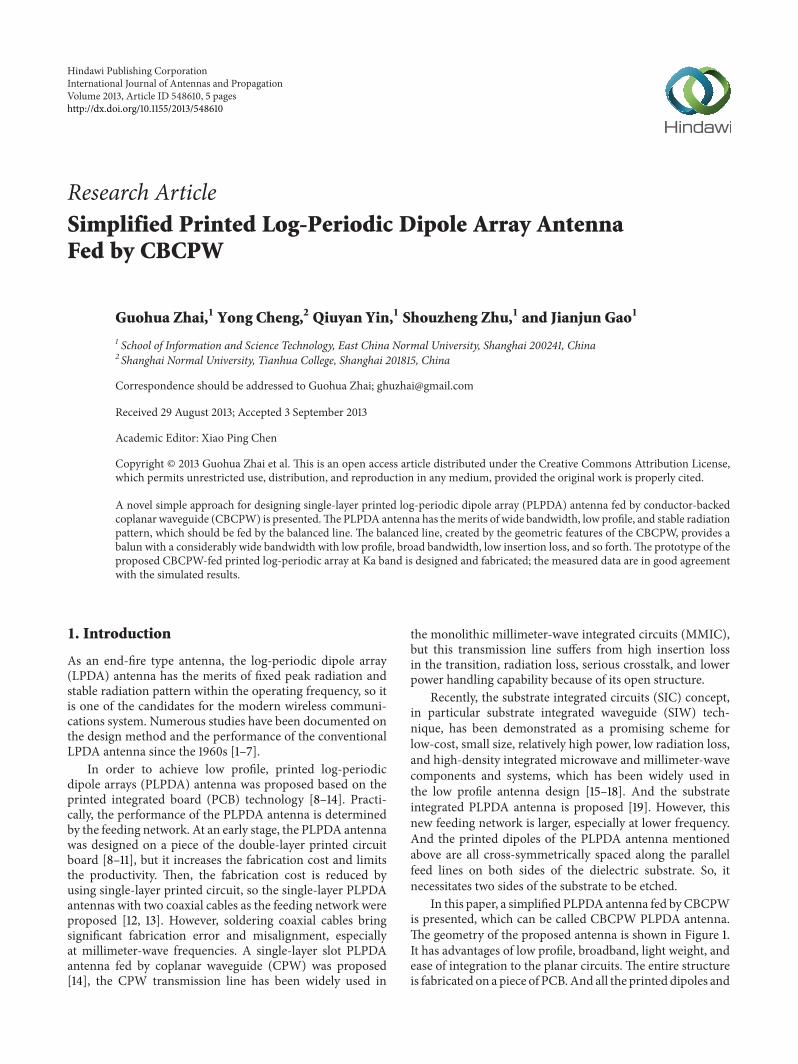
The proposed PLPDA antenna at 25GHz–40GHz isdesigned, fabricated, and measured. The measured andsimulated return losses of the proposed PLPDA antenna areshown in Figure 4. All of the measured results shown belowinclude the losses of 50Ω CBCPW insertion loss, the 2.4mmto 3.5mm adapters, and the SMA connectors. It can beseen that the |𝑆
11| is below −10 dB from 28GHz to 40GHz.
There is a little difference in the center frequency betweenmeasurement and simulation, which may be brought bythe fabrication errors and frequency dependent dielectricpermittivity without consideration in the simulation.
Figure 5 shows the measured antenna gain of the pro-posed antennas. The peak antenna gain of the CBCPWPLPDA antenna is 4.3 dBi at 34GHz. The measured antennagain of the CBCPW PLPDA antenna is less than that ofthe simulated results, which maybe brought by the losses ofthe SMA connector and the increasing substrate loss of theantenna at millimeter-waves.
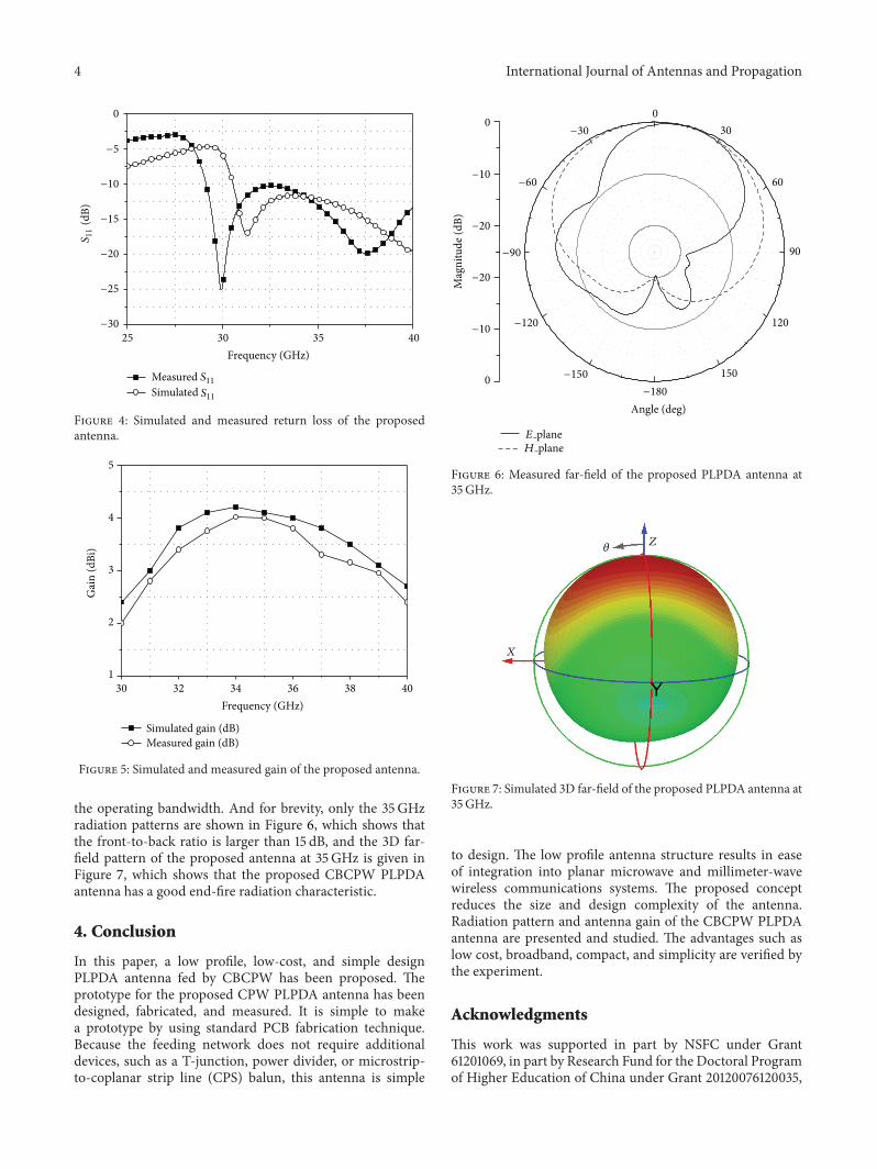
The far-field radiation pattern of the proposed antennais measured which shows the similar characteristics across
4 International Journal of Antennas and Propagation
25 30 35 40
0
Frequency (GHz)
−5
−10
−20
−25
−30
−15
S11
(dB)
Measured S11
S11Simulated
Figure 4: Simulated and measured return loss of the proposedantenna.
30 32 34 36 38 401
2
3
4
5
Gai
n (d
Bi)
Frequency (GHz)
Simulated gain (dB)Measured gain (dB)
Figure 5: Simulated and measured gain of the proposed antenna.
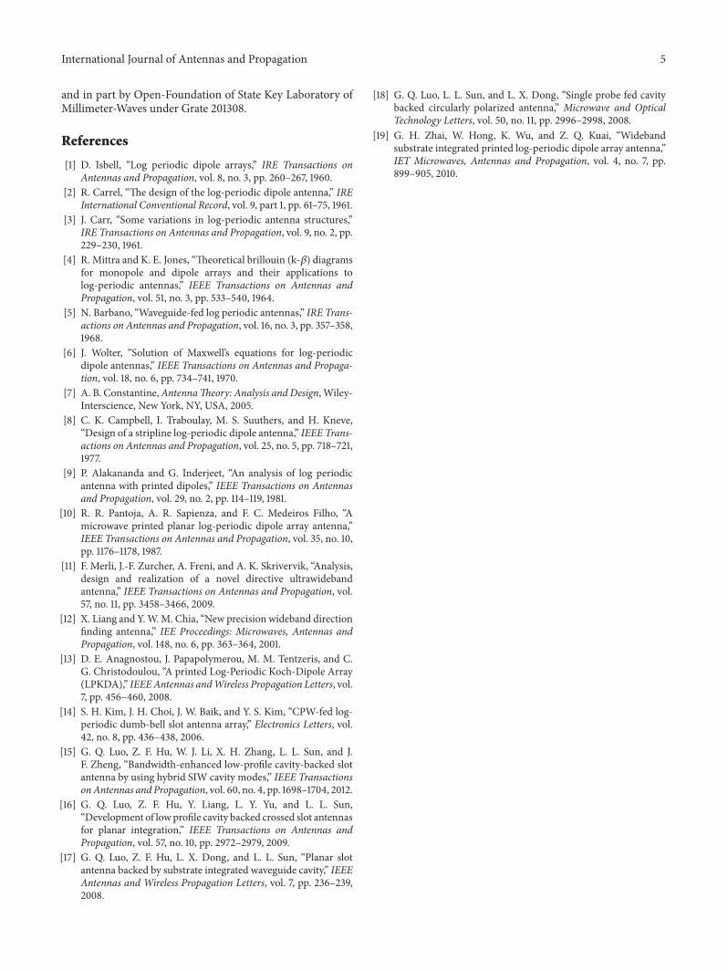
the operating bandwidth. And for brevity, only the 35GHzradiation patterns are shown in Figure 6, which shows thatthe front-to-back ratio is larger than 15 dB, and the 3D far-field pattern of the proposed antenna at 35GHz is given inFigure 7, which shows that the proposed CBCPW PLPDAantenna has a good end-fire radiation characteristic.
4. Conclusion
In this paper, a low profile, low-cost, and simple designPLPDA antenna fed by CBCPW has been proposed. Theprototype for the proposed CPW PLPDA antenna has beendesigned, fabricated, and measured. It is simple to makea prototype by using standard PCB fabrication technique.Because the feeding network does not require additionaldevices, such as a T-junction, power divider, or microstrip-to-coplanar strip line (CPS) balun, this antenna is simple
00
30
60
90
120
1500
−30
−60
−90
−120
−150
−180
−10
−10
−20
−20
Angle (deg)
Mag
nitu
de (d
B)
E planeH plane
Figure 6: Measured far-field of the proposed PLPDA antenna at35GHz.
𝜃Z
X
Figure 7: Simulated 3D far-field of the proposed PLPDA antenna at35GHz.
to design. The low profile antenna structure results in easeof integration into planar microwave and millimeter-wavewireless communications systems. The proposed conceptreduces the size and design complexity of the antenna.Radiation pattern and antenna gain of the CBCPW PLPDAantenna are presented and studied. The advantages such aslow cost, broadband, compact, and simplicity are verified bythe experiment.
Acknowledgments
This work was supported in part by NSFC under Grant61201069, in part by Research Fund for the Doctoral Programof Higher Education of China under Grant 20120076120035,
International Journal of Antennas and Propagation 5
and in part by Open-Foundation of State Key Laboratory ofMillimeter-Waves under Grate 201308.
References
[1] D. Isbell, “Log periodic dipole arrays,” IRE Transactions onAntennas and Propagation, vol. 8, no. 3, pp. 260–267, 1960.
[2] R. Carrel, “The design of the log-periodic dipole antenna,” IREInternational Conventional Record, vol. 9, part 1, pp. 61–75, 1961.
[3] J. Carr, “Some variations in log-periodic antenna structures,”IRE Transactions on Antennas and Propagation, vol. 9, no. 2, pp.229–230, 1961.
[4] R. Mittra and K. E. Jones, “Theoretical brillouin (k-𝛽) diagramsfor monopole and dipole arrays and their applications tolog-periodic antennas,” IEEE Transactions on Antennas andPropagation, vol. 51, no. 3, pp. 533–540, 1964.
[5] N. Barbano, “Waveguide-fed log periodic antennas,” IRE Trans-actions on Antennas and Propagation, vol. 16, no. 3, pp. 357–358,1968.
[6] J. Wolter, “Solution of Maxwell’s equations for log-periodicdipole antennas,” IEEE Transactions on Antennas and Propaga-tion, vol. 18, no. 6, pp. 734–741, 1970.
[7] A. B. Constantine,AntennaTheory: Analysis and Design, Wiley-Interscience, New York, NY, USA, 2005.
[8] C. K. Campbell, I. Traboulay, M. S. Suuthers, and H. Kneve,“Design of a stripline log-periodic dipole antenna,” IEEE Trans-actions on Antennas and Propagation, vol. 25, no. 5, pp. 718–721,1977.
[9] P. Alakananda and G. Inderjeet, “An analysis of log periodicantenna with printed dipoles,” IEEE Transactions on Antennasand Propagation, vol. 29, no. 2, pp. 114–119, 1981.
[10] R. R. Pantoja, A. R. Sapienza, and F. C. Medeiros Filho, “Amicrowave printed planar log-periodic dipole array antenna,”IEEE Transactions on Antennas and Propagation, vol. 35, no. 10,pp. 1176–1178, 1987.
[11] F. Merli, J.-F. Zurcher, A. Freni, and A. K. Skrivervik, “Analysis,design and realization of a novel directive ultrawidebandantenna,” IEEE Transactions on Antennas and Propagation, vol.57, no. 11, pp. 3458–3466, 2009.
[12] X. Liang and Y.W.M. Chia, “New precision wideband directionfinding antenna,” IEE Proceedings: Microwaves, Antennas andPropagation, vol. 148, no. 6, pp. 363–364, 2001.
[13] D. E. Anagnostou, J. Papapolymerou, M. M. Tentzeris, and C.G. Christodoulou, “A printed Log-Periodic Koch-Dipole Array(LPKDA),” IEEEAntennas andWireless Propagation Letters, vol.7, pp. 456–460, 2008.
[14] S. H. Kim, J. H. Choi, J. W. Baik, and Y. S. Kim, “CPW-fed log-periodic dumb-bell slot antenna array,” Electronics Letters, vol.42, no. 8, pp. 436–438, 2006.
[15] G. Q. Luo, Z. F. Hu, W. J. Li, X. H. Zhang, L. L. Sun, and J.F. Zheng, “Bandwidth-enhanced low-profile cavity-backed slotantenna by using hybrid SIW cavity modes,” IEEE TransactionsonAntennas and Propagation, vol. 60, no. 4, pp. 1698–1704, 2012.
[16] G. Q. Luo, Z. F. Hu, Y. Liang, L. Y. Yu, and L. L. Sun,“Development of lowprofile cavity backed crossed slot antennasfor planar integration,” IEEE Transactions on Antennas andPropagation, vol. 57, no. 10, pp. 2972–2979, 2009.
[17] G. Q. Luo, Z. F. Hu, L. X. Dong, and L. L. Sun, “Planar slotantenna backed by substrate integrated waveguide cavity,” IEEEAntennas and Wireless Propagation Letters, vol. 7, pp. 236–239,2008.
[18] G. Q. Luo, L. L. Sun, and L. X. Dong, “Single probe fed cavitybacked circularly polarized antenna,” Microwave and OpticalTechnology Letters, vol. 50, no. 11, pp. 2996–2998, 2008.
[19] G. H. Zhai, W. Hong, K. Wu, and Z. Q. Kuai, “Widebandsubstrate integrated printed log-periodic dipole array antenna,”IET Microwaves, Antennas and Propagation, vol. 4, no. 7, pp.899–905, 2010.

International Journal of
AerospaceEngineeringHindawi Publishing Corporationhttp://www.hindawi.com Volume 2014
RoboticsJournal of
Hindawi Publishing Corporationhttp://www.hindawi.com Volume 2014
Hindawi Publishing Corporationhttp://www.hindawi.com Volume 2014
Active and Passive Electronic Components
Control Scienceand Engineering
Journal of
Hindawi Publishing Corporationhttp://www.hindawi.com Volume 2014
International Journal of
RotatingMachinery
Hindawi Publishing Corporationhttp://www.hindawi.com Volume 2014
Hindawi Publishing Corporation http://www.hindawi.com
Journal ofEngineeringVolume 2014
Submit your manuscripts athttp://www.hindawi.com
VLSI Design
Hindawi Publishing Corporationhttp://www.hindawi.com Volume 2014
Hindawi Publishing Corporationhttp://www.hindawi.com Volume 2014
Shock and Vibration
Hindawi Publishing Corporationhttp://www.hindawi.com Volume 2014
Civil EngineeringAdvances in
Acoustics and VibrationAdvances in
Hindawi Publishing Corporationhttp://www.hindawi.com Volume 2014
Hindawi Publishing Corporationhttp://www.hindawi.com Volume 2014
Electrical and Computer Engineering
Journal of
Advances inOptoElectronics
Hindawi Publishing Corporation http://www.hindawi.com
Volume 2014
The Scientific World JournalHindawi Publishing Corporation http://www.hindawi.com Volume 2014
SensorsJournal of
Hindawi Publishing Corporationhttp://www.hindawi.com Volume 2014
Modelling & Simulation in EngineeringHindawi Publishing Corporation http://www.hindawi.com Volume 2014
Hindawi Publishing Corporationhttp://www.hindawi.com Volume 2014
Chemical EngineeringInternational Journal of Antennas and
Propagation
International Journal of
Hindawi Publishing Corporationhttp://www.hindawi.com Volume 2014
Hindawi Publishing Corporationhttp://www.hindawi.com Volume 2014
Navigation and Observation
International Journal of
Hindawi Publishing Corporationhttp://www.hindawi.com Volume 2014
DistributedSensor Networks
International Journal of
Related Documents