Design of CO Emission Monitoring System for Motorized Vehicle Based on ATMEGA8535 Microcontroller Tika Iswara Engineering Physics Department, Faculty of Engineering, Gadjah Mada University, Yogyakarta - Indonesia http://tf.ugm.ac.id e-mail : [email protected] Abstract According to decision Minister of Environmental Affair number 141, 2003, since January 2005 every new motorized vehicle must obey to EURO 2 emission standart, while the old type of motorized vehicle have a chance to adapted until 2007. Carbonmonoxide is one of parameter which measured on EURO 2 emission standart. Until now, the quantity of emission monitoring instrument, especially for CO is limited, if compared with amount of motorized vehicle that operating on the road. A carbonmonoxide emission monitoring system had been made based on ATMEGA8535 microcontroller which had on chip 10-bit ADC. The system used an electrochemical sensor, TGS5042. Liquid Crystal Display M1632 and 5 colors LED used as output of the system. The system have measurement range 0 ppm until 1.000 ppm, accuracy + 20 % (0 ppm until 100 ppm), + 15 % (100 ppm until 500 ppm), resolution 1 ppm, respon time + 1 second and sensor have life time 7 years under natural residental condition such as 20 0 C/40% RH. The system real time and portable operated, which can valued result of the measurement into 5 category, there are good (0 ppm until 50 ppm), bad (51 ppm until 200 ppm), indisposed (201 ppm until 400 ppm), very indisposed (401 ppm until 800 ppm) and dangerous (biger 801 ppm). Keywords : EURO 2 emission standart, motorized vehicle, ATMEGA8535 microcontroller, TGS5042, real time, portable, LCD M1632, LED. 1. INTRODUCTION The relation between environmental and engineering design is one aspect which influence human life. An instrument that created, some time not safety for environment or surrounding because this side effects such us CO, SO, HC and NOx. Today people have insteresting about healty and safety instrument. It’s mean that all technology product must have concern about environment or people will leaving this product from market. Air quality is one factor that used for monitoring healthy of environment. The growth of fosil fuel today, had effects decreasing the air quality, because their gas emission such as carbonmonoxice, hydrocarbon, sulfur dioksida and nitrogen dioksida. It’s toxic gas and will attack the human live. Carbonmonoxide can kill people, in some ppm amount and periode. Indonesia Minister of Environmental had the regulation about gas emission from motorized vehicle. This regulation said that since January 2005 every new motorized vehicle must obey to EURO 2 emission standart, while the old type of motorized vehicle have a chance to machine adapted until 2007. Carbonmonoxide is one of parameter which

Welcome message from author
This document is posted to help you gain knowledge. Please leave a comment to let me know what you think about it! Share it to your friends and learn new things together.
Transcript

Design of CO Emission Monitoring System for Motorized VehicleBased on ATMEGA8535 Microcontroller
Tika IswaraEngineering Physics Department,
Faculty of Engineering, Gadjah Mada University, Yogyakarta - Indonesiahttp://tf.ugm.ac.id e-mail : [email protected]
Abstract
According to decision Minister of Environmental Affair number 141, 2003, since January 2005every new motorized vehicle must obey to EURO 2 emission standart, while the old type of motorizedvehicle have a chance to adapted until 2007. Carbonmonoxide is one of parameter which measured onEURO 2 emission standart. Until now, the quantity of emission monitoring instrument, especially for CO islimited, if compared with amount of motorized vehicle that operating on the road.
A carbonmonoxide emission monitoring system had been made based on ATMEGA8535microcontroller which had on chip 10-bit ADC. The system used an electrochemical sensor, TGS5042.Liquid Crystal Display M1632 and 5 colors LED used as output of the system. The system havemeasurement range 0 ppm until 1.000 ppm, accuracy + 20 % (0 ppm until 100 ppm), + 15 % (100 ppm until500 ppm), resolution 1 ppm, respon time + 1 second and sensor have life time 7 years under naturalresidental condition such as 200C/40% RH. The system real time and portable operated, which can valuedresult of the measurement into 5 category, there are good (0 ppm until 50 ppm), bad (51 ppm until 200ppm), indisposed (201 ppm until 400 ppm), very indisposed (401 ppm until 800 ppm) and dangerous (biger801 ppm).
Keywords : EURO 2 emission standart, motorized vehicle, ATMEGA8535 microcontroller, TGS5042, real time, portable, LCD M1632, LED.
1. INTRODUCTION
The relation between environmental and engineering design is one aspect whichinfluence human life. An instrument that created, some time not safety for environment orsurrounding because this side effects such us CO, SO, HC and NOx. Today people haveinsteresting about healty and safety instrument. It’s mean that all technology product musthave concern about environment or people will leaving this product from market.
Air quality is one factor that used for monitoring healthy of environment. The growthof fosil fuel today, had effects decreasing the air quality, because their gas emission suchas carbonmonoxice, hydrocarbon, sulfur dioksida and nitrogen dioksida. It’s toxic gas andwill attack the human live. Carbonmonoxide can kill people, in some ppm amount andperiode.
Indonesia Minister of Environmental had the regulation about gas emission frommotorized vehicle. This regulation said that since January 2005 every new motorizedvehicle must obey to EURO 2 emission standart, while the old type of motorized vehiclehave a chance to machine adapted until 2007. Carbonmonoxide is one of parameter which

measured on EURO 2 emission standart. Until now, the quantity of emission monitoringinstrument, especially for CO is limited, if compared with number of motorized vehiclethat operating on the road. 1.1 Problem Definition Design of CO emission monitoring system for motorized vehicle based onATMEGA85835 microcontroller. This system portable and real time.1.2 Purpose of Research
This research to get a portable CO monitoring system based on AVR microcontrollerATMEGA8535, displayed by a modul LCD M1632 and LED indicator. The system willused for measure carbonmonoxide concentration from 0 ppm until 1.000 ppm.
2. CARBONMONOXIDE
Carbon and oxygen will create carbonmonoxide when unperfect chemical reactionoccurred in machine. Based on research in America 60,6 % CO emission from motorizedvehicle, 16,8 % CO from industry, 5,6 % CO from power plant and 3,5 % from waste(City of Fort Collins home page/air quality/carbon-monoxide.php). This modestlychemical reaction occurred in motorized vehicle combustion.
Fuel + αO2 βCO + γH2O
CO + 1/2O2 CO2
Carbonmonoxide is a toxic gas, because the stronger reaction with haemoglobin thanoksigen reaction with haemoglobin. If occured reaction with haemoglobin in blood ofhuman, oksigen can’t spread in blood because carbosihaemoglobin more stable thanoksihaemoglobin. The decrease of oksigen in blood make human died. This is thecomplete reaction.
CO(g) + Hb(l) HbCO(l)
O2(g) + Hb(l) HbO2(l)
3. ATMEGA8535 MICROCONTROLLER
ATmega835 is a low-power CMOS 8-bit microcontroller based on the AVR enhancedRISC architecture. By executing instructions in a single clock cycle, the ATmega8535achieves throughputs approaching 1 MIPS per MHZ allowing the system designer tooptimize power consumption versus processing speed. This microcontroller created byATMEL inc.
The ATmega8535 feature consist of 32 x 8 General Purpose Working Registers, up to16 MIPS throughput at 16 MHZ, 130 Powerful Instruction, 8K bytes of In-System Self-Programmable Flash, Endurance : 10,000 Write/Erase Cycles, 512 Bytes EEPROM withEndurance : 100,000 Write/Erase Cycles, 8-channel 10-bit ADC, Programmable SerialUSART, 512 Bytes Internal SRAM, etc.
2
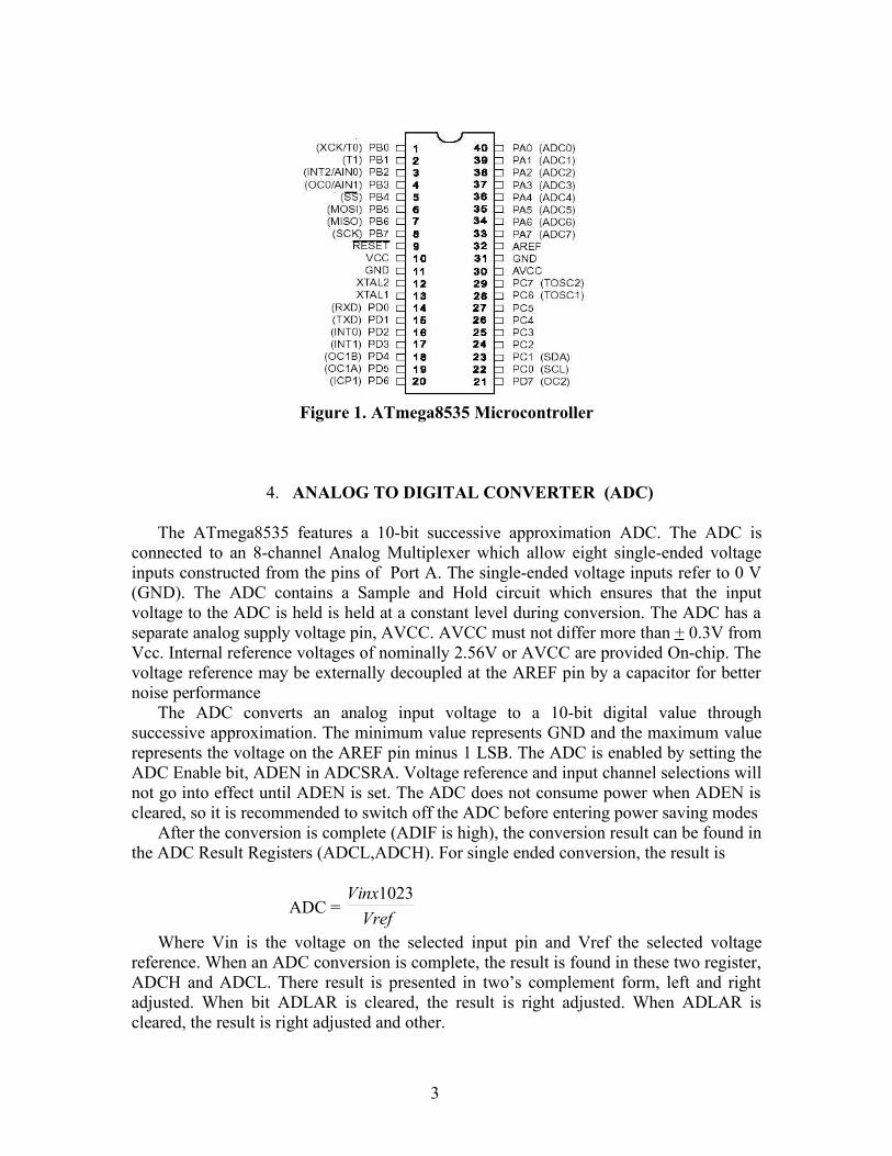
Figure 1. ATmega8535 Microcontroller
4. ANALOG TO DIGITAL CONVERTER (ADC)
The ATmega8535 features a 10-bit successive approximation ADC. The ADC isconnected to an 8-channel Analog Multiplexer which allow eight single-ended voltageinputs constructed from the pins of Port A. The single-ended voltage inputs refer to 0 V(GND). The ADC contains a Sample and Hold circuit which ensures that the inputvoltage to the ADC is held is held at a constant level during conversion. The ADC has aseparate analog supply voltage pin, AVCC. AVCC must not differ more than + 0.3V fromVcc. Internal reference voltages of nominally 2.56V or AVCC are provided On-chip. Thevoltage reference may be externally decoupled at the AREF pin by a capacitor for betternoise performance
The ADC converts an analog input voltage to a 10-bit digital value throughsuccessive approximation. The minimum value represents GND and the maximum valuerepresents the voltage on the AREF pin minus 1 LSB. The ADC is enabled by setting theADC Enable bit, ADEN in ADCSRA. Voltage reference and input channel selections willnot go into effect until ADEN is set. The ADC does not consume power when ADEN iscleared, so it is recommended to switch off the ADC before entering power saving modes
After the conversion is complete (ADIF is high), the conversion result can be found inthe ADC Result Registers (ADCL,ADCH). For single ended conversion, the result is
ADC = VrefVinx1023
Where Vin is the voltage on the selected input pin and Vref the selected voltagereference. When an ADC conversion is complete, the result is found in these two register,ADCH and ADCL. There result is presented in two’s complement form, left and rightadjusted. When bit ADLAR is cleared, the result is right adjusted. When ADLAR iscleared, the result is right adjusted and other.
3
The Right Adjusted ResultBit 15 Bit 14 Bit 13 Bit 12 Bit 11 Bit 10 Bit 9 Bit 8- - - - - - ADC9 ADC8ADC7 ADC6 ADC5 ADC4 ADC3 ADC2 ADC1 ADC0Bit 7 Bit 6 Bit 5 Bit 4 Bit 3 Bit 2 Bit 1 Bit 0
The Left Adjusted ResultBit 15 Bit 14 Bit 13 Bit 12 Bit 11 Bit 10 Bit 9 Bit 8ADC9 ADC8 ADC7 ADC6 ADC5 ADC4 ADC3 ADC2ADC1 ADC0 - - - - - -Bit 7 Bit 6 Bit 5 Bit 4 Bit 3 Bit 2 Bit 1 Bit 0
5. LIQUID CRYSTAL DISPLAY
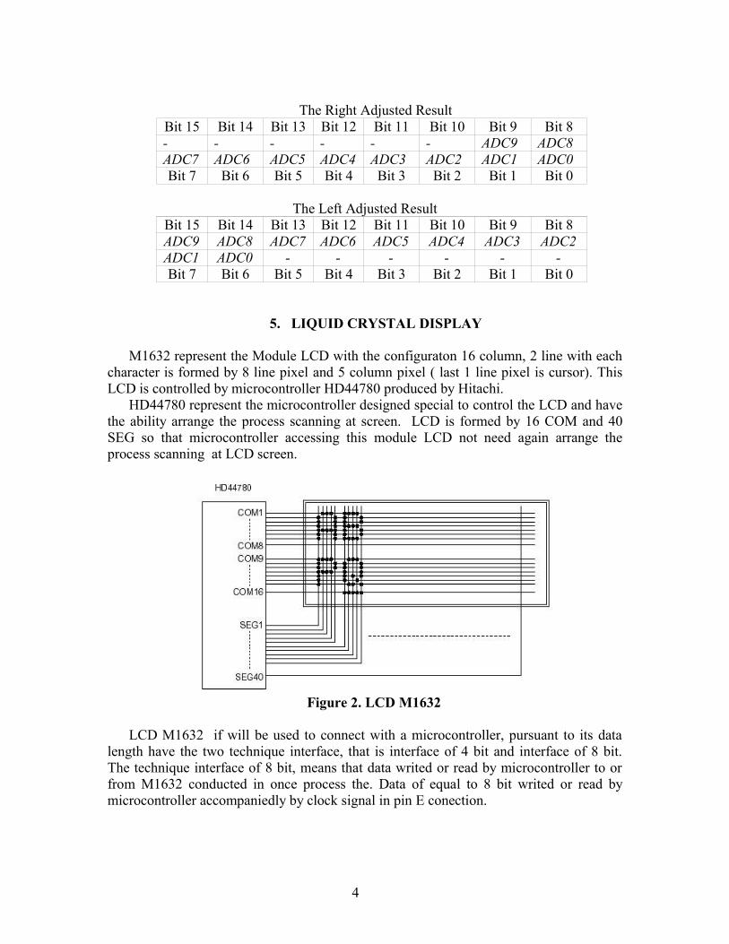
M1632 represent the Module LCD with the configuraton 16 column, 2 line with eachcharacter is formed by 8 line pixel and 5 column pixel ( last 1 line pixel is cursor). ThisLCD is controlled by microcontroller HD44780 produced by Hitachi.
HD44780 represent the microcontroller designed special to control the LCD and havethe ability arrange the process scanning at screen. LCD is formed by 16 COM and 40SEG so that microcontroller accessing this module LCD not need again arrange theprocess scanning at LCD screen.
Figure 2. LCD M1632
LCD M1632 if will be used to connect with a microcontroller, pursuant to its datalength have the two technique interface, that is interface of 4 bit and interface of 8 bit.The technique interface of 8 bit, means that data writed or read by microcontroller to orfrom M1632 conducted in once process the. Data of equal to 8 bit writed or read bymicrocontroller accompaniedly by clock signal in pin E conection.
4
6. RESEARCH EXECUTION
The substance used in research is 1. Microcontroller AVR ATMEGA8535 ATMEL 2. LCD M1632, LED 3. Sensor of CO TGS5042, IC Op-Amp OP-07 4. Oscillator Crystal 12 MHZ, Voltage Regulator 7805 5. Resistor, capacitor, diode 6. Acrylic 1,5 mm, 3mm, PCB 7. Rainbow Cable 10 band, cable socket, socket 10 pin 8. Motor DC 9 V, nut, saklar 9. Battery 9 V, 12 V pile alkaline
Appliance used by 1. Digital multimeter 2. Mechanic Equipments ( drill the, saw, tight-fisted, screwdriver)3. Solder and ekstractor, motorbike 4. Power Supply 5V, 9V 5. Personal Computer, dongle, software of AVR Studio 4, Ponyprog2000, OrCAD 9.2
Research managery cover the phase 1. Literature study concerning measurement instrument of CO 2. Ready of appliance and substance 3. Software design use the AVR Studio 4 4. Scheme of PCB microcontroller and system sensor used Orcad 9.2 5. Examination the sensor ouput through circuit of sensor substitution 6. Examination the amplifier circuit for sensor TGS5042 7. Comparing data of ADC reference and result of circuit examination sensor to determine amount of gain factor 8. Examination ADC of microcontroller ATMEGA8535 9. Determination voltage input of ADC showing conversion value which equal to 1.000.10. System examination with the input in the form of electrics current variation yielding output in the form of conversion value of ADC displayed on LCD M1632
11. Determination rectify result of measurement. 12. Making of appliance tidiness.
13. Field examination. 14. Analysis the result and making of research report
5
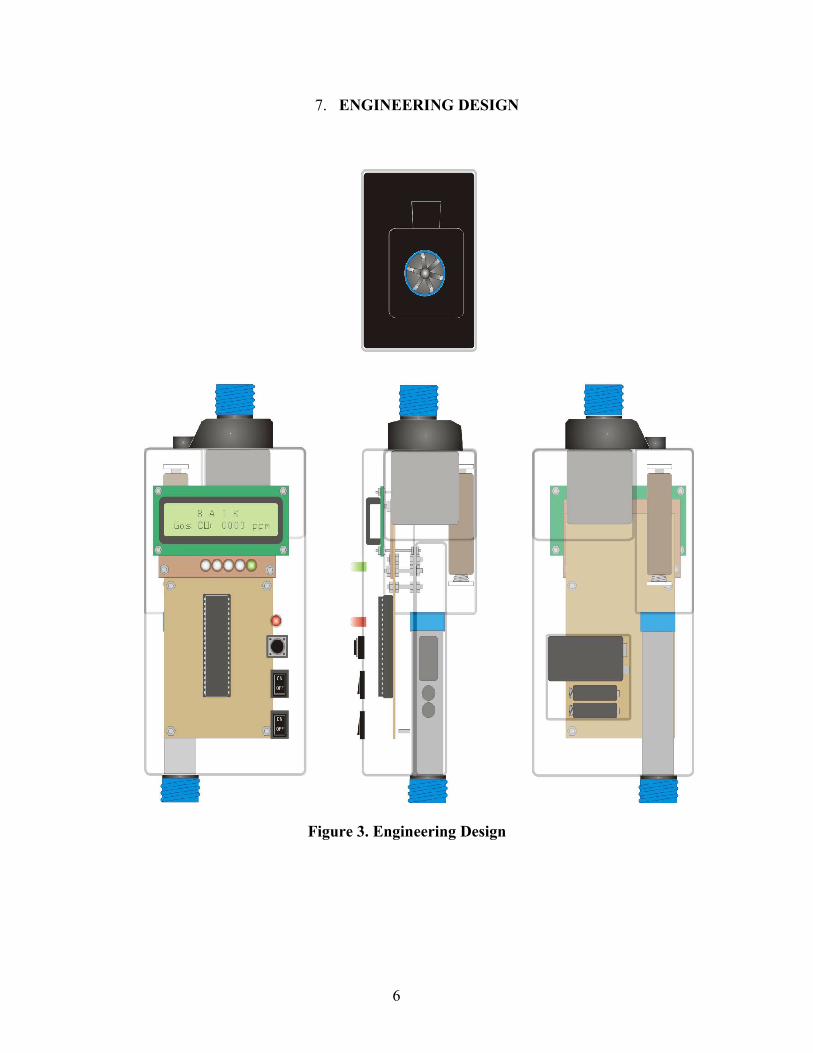
7. ENGINEERING DESIGN
Figure 3. Engineering Design
6

Figure 4. Schematic of CO Monitoring System
8. ANALYSE RESULT
Intake of examination data conducted to use the measuring instrument which havebeen ascertained good in a condition. Though the measuring instrument own the mistakevalue, measurement mistake coming from measuring instrument disregarded in analysisresult. Data of the result of examination then processed by software of MATLAB 6..Equation in the following is utilized to obtain the value of measurement deviation.
%100xR
RTDeviation −=
in this case, T : Result of Measurement R : Assess The Component Reference
Method of calibrate usually done by comparing new instrument with standartmeasuring instrument. Method utilized for the gauging of appliance made by comparingthe data result of system examination with the data of component reference weared, thatis sensor TGS5042. This is simple means that compare electric current of TGS5042 withADC result of ATmega8535 microcontroller.
The result of deviation system which have been made smaller than deviation ofsensor TGS5042 reference, big hence deviation coming from reference data utilized by asdeviation determination of entire all system, conversely; because in fact assess thedeviation of larger ones represent the smaller deviation contribution. So that assess thelarger ones deviation, more dominant give the measurement mistake.
As according to used sensor type, measurement parameter determined fromexamination result, that is accuration, resolution, and time respon. The parameterrepresent the value which is ever determined at measuring instrument being based onelectrochemical sensor.
7

9. RESULT AND SOLUTION
9.1 Examination of Current to Voltage Circuit The circuit of current to voltage convertion have function to obtain voltage
characteristic from input which is in the form of electrics current. Span the voltageyielded by sensor, when there are CO in the range 0 ppm till 1.000 ppm important toknow, because microcontroller will use the change of voltage gyration to be translatedinto binary logic. Figure 5 representing circuit of examination of current to voltageconvertion.
Figure 5. Circuit of Current to Voltage Convertion
Sensor of TGS5042 which used own function as source of electrics current. Asaccording to reference data, sensor will awaken the electrics current in the range 0 A till2,4 A. Battery 1,5 V and resistor 2 M have function to replace the sensor function.Electrics current of equal to 0 A till 2,4 A obtained from battery 1,5 V stringed up breakevenly by resistor variable 2 M.
8
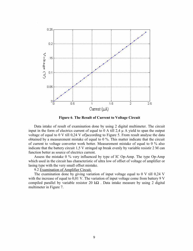
Figure 6. The Result of Current to Voltage Circuit
Data intake of result of examination done by using 2 digital multimeter. The circuitinput in the form of electrics current of equal to 0 A till 2,4 µ A yield to span the outputvoltage of equal to 0 V till 0,24 V of]according to Figure 5. From result analyse the dataobtained by a measurement mistake of equal to 0 %. This matter indicate that the circuitof current to voltage converter work better. Measurement mistake of equal to 0 % alsoindicate that the battery circuit 1,5 V stringed up break evenly by variable resistir 2 M canfunction better as source of electrics current.
Assess the mistake 0 % very influenced by type of IC Op-Amp. The type Op-Ampwhich used in the circuit has characteristic of ultra low of offset of voltage of amplifier orlasing type with the very small offset mistake.
9.2 Examination of Amplifier Circuit. The examination done by giving variation of input voltage equal to 0 V till 0,24 V
with the increase of equal to 0,01 V. The variation of input voltage come from battery 9 Vcompiled parallel by variable resistor 20 kΩ . Data intake measure by using 2 digitalmultimeter in Figure 7.
9
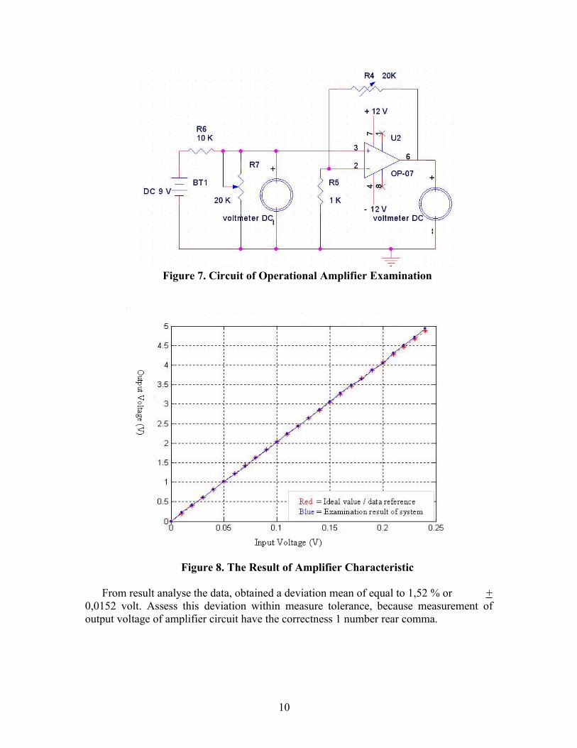
Figure 7. Circuit of Operational Amplifier Examination
Figure 8. The Result of Amplifier Characteristic
From result analyse the data, obtained a deviation mean of equal to 1,52 % or +0,0152 volt. Assess this deviation within measure tolerance, because measurement ofoutput voltage of amplifier circuit have the correctness 1 number rear comma.
10

9.3 Examination of ADC ATMEGA8535 Examination ADC conducted with giving input in the form of voltage variation of 0
V till 5 V with the increase equal to 0,1 V. Pin A0 at port A function as analogous voltageinput. The result of conversion in the form of binary value ‘ 0000000000’ till ‘1111111111’. The binary value then processed and converted by microcontroller becomethe value equal to 0 till 1023, then displayed at LCD. Graph the result of examinationADC like at Figure 9.
Figure 9. The Result of ADC Examination
From the result analyse the data, a deviation mean of equal to 3,04 % or + 0,0304volt.
9.4 System Examination Examination to system or engineering design which have been designed to be
conducted without entangling sensor TGS5042. System examination [done/conducted][blike Picture 5.7 with giving input in the form of variation [of] of electrics current [of]equal to 0 A till 2,4 A.
System output in the form of conversion value of ADC presented at LCD ( showingrate of gas CO in set of ppm), assessment of quality of gas CO, and blaze the lamp LED 5colour. The result of system examination presented by graph at Figure 10.
11

Figure 10. Result of Monitoring System Examination
Assessment the examination result of CO become 5 category of pursuant to data atTable 1. While determination of colour of LED adapted by condition of assessment of COconcentration. The system which have been made show 5 category, there are green colouris good condition indication, yellow mean bad, pink mean indisposed, red mean veryindisposed, and blue mean dangerous.
Table 1. The Category of CO Concentration Effect for Human BodySecond Row of
LCD ScreenADC RegisterADCH/ADCL
First Row ofLCD Screen
Color of LED
0 – 50 $0000 - $0032 good Green51 – 200 $0033 - $00C8 bad Yellow201 – 400 $00C9 - $0190 indisposed Pink401 – 800 $0191 - $0320 very indisposed Red
Biger of 801 $0321 - $03FF dangerous Blue
From result analyse the data, obtained by deviation average value equal to 2,87 %.The deviation average of equal to 2,87 % will be used to determine the system accurationwhich have been designed.
12

10. CONCLUSION
1. Monitoring system of CO can work by portable and real time, capable to beoperated to measure the rate of CO motorized vehicle.
2. Monitoring system have measurement span 0 ppm till 1.000 ppm, accuration + 20% ( 0 ppm till 100 ppm), + 15 % ( 100 ppm till 500 ppm) and 1 ppm resolution.
3. System which have been made able to give the assessment of CO quality pursuantinto 5 category, that is goodness ( 0 ppm till 50 ppm of CO), bad ( 51 ppm till 200ppm of CO), indisposed ( 201 ppm till 400 ppm of CO), very indisposed ( 401ppm till 800 ppm of CO) and dangerous ( above 801 ppm of CO).
13

ENCLOSURE
[ Top Side ]
ATmega8535 microcontroller LCD M1632 LED indicator
14

;***********************************************************************; Title : Sistem Monitoring Gas CO Kendaraan Bermotor; Target : ATmega8535; Hari/Tanggal : Jum'at/21 Januari 2006; Engineer : Iswara;***********************************************************************
; Bismillaahirrahmaanirraahiim
.include "m8535def.inc"
.def tmp =r16
.def tmpa =r17
.def tout =r18
.def tmpT1 =r19
.def tmpLCD =r20
.def tmpLed =r23
.def plus =r24
.def plus1 =r25;LCD.equ RS =0 ;kaki pin 0 pada portd.equ RW =1 ;kaki pin 1 pada portd.equ E =2 ;kaki pin 2 pada portd;Bin2BCD16.equ AtBCD0 =13 ;alamat tBCD0.equ AtBCD2 =15 ;alamat tBCD1.def tBCD0 =r13 ;nilai digit BCD 1 dan 0.def tBCD1 =r14 ;nilai digit BCD 3 dan 2.def tBCD2 =r15 ;nilai digit BCD 4.def fbinL =r16 ;nilai biner dari bit rendah.def fbinH =r17 ;nilai biner dari bit tinggi.def cnt16a =r18 ;kalang pencacah.def tmp16a =r19 ;nilai register sementara
;******************************; Interupsi;******************************.cseg.org 0000
rjmp Mulai ;menuju preparasi.org $00E ;vektor interupsi ADC
rjmp St_con ;loncatan agar terjadi interupsi
;*******************************************; Prosedur-prosedur;*******************************************;******************************; Prosedur interupsi ADC;******************************St_con:
in r21,ADCL in r22,ADCHldi tmp,0b11101111out ADCSRA,tmpseireti
;*****************************; Prosedur tampilan LCD awal;*****************************Tampil:
lpmtst r0breq PL
15

mov tmpa,r0rcall lcdputadiw ZL,1rjmp Tampil
PL:ret
AWAL:rcall baris1ldi ZH,HIGH(2*StAWAL1)ldi ZL,LOW(2*StAWAL1)rcall tampilrcall baris2ldi ZH,HIGH(2*StAWAL2)ldi ZL,LOW(2*StAWAL2)rcall tampilret
;============================================================PENYUSUNAN:
rcall baris1ldi ZH,HIGH(2*StNama)ldi ZL,LOW(2*StNama)rcall tampilrcall baris2ldi ZH,HIGH(2*StNIM)ldi ZL,LOW(2*StNIM)rcall tampilret
;============================================================kampus:
rcall baris1ldi ZH,HIGH(2*StKampus)ldi ZL,LOW(2*StKampus)rcall tampilrcall baris2ldi ZH,HIGH(2*StKota)ldi ZL,LOW(2*StKota)rcall tampilret
Judul:rcall baris1ldi Zh,high(2*StAwal1)ldi Zl,low(2*StAwal1)rcall tampil
rcall baris2ldi Zh,high(2*StJudul2)ldi Zl,low(2*StJudul2)rcall tampilret
baris1:ldi tmpa,0b00000010rcall lcdcmdret
baris2:ldi tmpa,0b11000000rcall lcdcmdret
;****************************; Prosedur BCD;****************************;bin2BCD16=Konversi biner 16 bit ke BCDbin2BCD16:
ldi cnt16a,16 ;inisialisasi kalang pencacahclr tBCD2 ;memberi logika "0" (3 bytes)
16

clr tBCD1clr tBCD0clr ZH ;memberi logika "0" pada ZH
bBCDx_1:lsl fbinL ;pergeseran nilai masukanrol fbinH ;through all bytesrol tBCD0rol tBCD1rol tBCD2dec cnt16a ;pengurangan kalang pencacahbrne bBCDx_2 ;if counter not zeroret ;return
bBCDx_2:ldi r30,AtBCD2+1 ;Z points to result MSB+1bBCDx_3:
ld tmp16a,-Z ;get (Z) with pre-decrementsubi tmp16a,-$03 ;tambahkan dengan nilai 0x03sbrc tmp16a,3 ;if bit 3 not clearst Z,tmp16a ;store backld tmp16a,Z ;get(Z)subi tmp16a,-$30 ;add 0x30sbrc tmp16a,7 ;if bit 7 not clearst Z,tmp16a ;store backcpi ZL,AtBCD0 ;done all three?brne bBCDx_3 ;loop again if notrjmp bBCDx_1
;****************************************; Prosedur tunda;****************************************tunda:
ldi tmpT1,250lagi:
dec tmpT1brne lagidec toutbrne tundaret
;************************; Prosedur LCD;*************************************************; Prosedur tunggu LCD;*************************************************TungguLCD:
ldi tmpLCD,$07out ddrd,tmpLCDsbi portd,RWcbi portd,RS
looptg:sbi portd,Ecbi portd,Ein tmpLCD,pindsbi portd,Ecbi portd,Esbrc tmpLCD,6rjmp looptgser tmpLCDout ddrd,tmpLCDret
;**************************************************; Prosedur kirim perintah ke LCD;*************************************************LCDCMD:
rcall tungguLCDmov tmpLCD,tmparor tmplcd
17

andi tmpLCD,$f8out portd,tmpLCDsbi portd,Ecbi portd,Emov tmpLCD,tmpaswap tmpLCDror tmplcdandi tmpLCD,$f8out portd,tmpLCDsbi portd,Ecbi portd,Esbi portd,RWsbi portd,RSret
;**************************************************; Prosedur kirim karakter;**************************************************LCDPUT:
rcall tungguLCDcbi portd,RWsbi portd,RSin tmp,portdmov tmpLCD,tmparor tmplcdandi tmpLCD,$f8out portd,tmpLCDsbi portd,RSsbi portd,Ecbi portd,Emov tmpLCD,tmpaswap tmpLCDror tmplcdandi tmpLCD,$f8out portd,tmpLCDsbi portd,RSsbi portd,Ecbi portd,Esbi portd,RWret
;***************************************; Preparasi;***************************************Mulai:
ldi r16,High(RAMEND)out SPH,r16ldi r16,low(RAMEND)out SPL,r16ser tmpout ddrd,tmpout portd,tmpser tmpout ddrb,tmpout portb,tmpclr tmpout ddra,tmpldi tmp,$40out ADMUX,tmpsei
;******************************************InitLCD:
cbi portd,RWcbi portd,RS
18

ldi tout,250rcall tundaldi tmp,$30out portd,tmpsbi portd,Ecbi portd,Eldi tout,80rcall tundaldi tmp,$30out portd,tmpsbi portd,Ecbi portd,Eldi tout,2rcall tundaldi tmp,$30out portd,tmpsbi portd,Ecbi portd,Eldi tmp,$20out portd,tmpsbi portd,Ecbi portd,Eldi tmpa,0b00101000rcall LCDCMDldi tmpa,0b00001000rcall LCDCMDldi tmpa,0b00001100rcall LCDCMDldi tmpa,0b00000010rcall LCDCMDldi tmpa,0b00000110rcall LCDCMDrcall Awalldi tmp,$3Fldi tmpa,$2F
wAwal:rcall Tundadec tmpbrne wAwalrcall Penyusunanldi tout,250 ;tunggu sdktnya 15 ms stlh power uprcall Tundaldi tmpa,$2F
akampus:rcall tundadec tmpabrne akampusrcall kampusldi tout,250 ;tunggu sdktnya 15 ms stlh power upldi tmpa,$2F
tunggu1:rcall tundadec tmpabrne tunggu1rcall judulldi tmp,0b10101111out ADCSRA,tmpseisbi ADCSRA,ADSC
;***************************************; Program Utama;***************************************main:
mov fbinL,r21
19

mov fbinH,r22rcall bin2BCD16 ;konversi biner ke BCDrcall nilai_gas ;loncat ke penilaian kualitas udaraldi tmpa,$cb rcall lcdcmdmov tmpa,tbcd0andi tmpa,$0fldi tmp,$30add tmpa,tmprcall lcdputldi tmpa,$carcall lcdcmdmov tmpa,tbcd0andi tmpa,$f0swap tmpaldi tmp,$30add tmpa,tmprcall lcdputldi tmpa,$c9rcall lcdcmdmov tmpa,tbcd1andi tmpa,$0fldi tmp,$30add tmpa,tmprcall lcdputldi tmpa,$c8rcall lcdcmdmov tmpa,tbcd1andi tmpa,$f0swap tmpaldi tmp,$30add tmpa,tmprcall lcdputrjmp main
;**********penyalaan LED & tampilan baris pertama LCD****************nyala1:
;*** menampilkan tulisan 'B A I K' ***rcall baris1ldi Zh,high(2*StNilai1)ldi Zl,low(2*StNilai1)rcall tampilrcall baris2ldi Zh,high(2*StJudul2)ldi Zl,low(2*StJudul2)rcall tampilldi tmpLed,0b01111111 ;led hijau menyalaout portb,tmpLedret
nyala2: ;*** menampilkan tulisan 'TIDAK BAIK' ***
rcall baris1ldi Zh,high(2*StNilai2)ldi Zl,low(2*StNilai2)rcall tampilrcall baris2ldi Zh,high(2*StJudul2)ldi Zl,low(2*StJudul2)rcall tampilldi tmpLed,0b10111111 ; led kuning menyala out portb,tmpLedret
nyala3: ;*** menampilkan tulisan 'TIDAK SEHAT' ***
rcall baris1ldi Zh,high(2*StNilai3)ldi Zl,low(2*StNilai3)
20

rcall tampilrcall baris2ldi Zh,high(2*StJudul2)ldi Zl,low(2*StJudul2)rcall tampilldi tmpLed,0b11011111 ;led merah muda menyalaout portb,tmpLedret
nyala4: ;*** menampilkan tulisan 'SANGAT TDK SEHAT' ***
rcall baris1ldi Zh,high(2*StNilai4)ldi Zl,low(2*StNilai4)rcall tampilrcall baris2ldi Zh,high(2*StJudul2)ldi Zl,low(2*StJudul2)rcall tampilldi tmpLed,0b11101111 ;led merah menyalaout portb,tmpLedret
nyala5: ;*** menampilkan tulisan 'BERBAHAYA !' ***
rcall baris1ldi Zh,high(2*StNilai5)ldi Zl,low(2*StNilai5)rcall tampilrcall baris2ldi Zh,high(2*StJudul2)ldi Zl,low(2*StJudul2)rcall tampilldi tmpLed,0b11110111 ;led biru menyalaout portb,tmpLedret
;*****penilaian hasil pengukuran*****nilai_gas :
cpi r22,3 ;nilai register ADC=0b11xxxxxxxxbreq loncat2cpi r22,2 ; bandingkan nilai r22 dengan 2breq nyala4cpi r22,1breq loncat1cpi r21,51 ;bandingkan hasil konversi dengan 51 ppmbrlo nyala1 ; jika lebih kecil dari 51 ppm meloncat ke:nyala1cpi r22,0brne loncat1cpi r21,201; bandingkan hasil konversi dengan 201 ppmbrlo nyala2 ; jika lebih kecil dari 201 ppm meloncat ke:nyala2
loncat1:cpi r22,0breq nyala3mov plus,r21 ; copy nilai r21 ke register plus(r24)mov plus1,r22 ; copy nilai r22 ke register plus1(r25)add plus,plus1 ;menjumlah nilai r21(ADCL) dan r22(ADCH)cpi plus,$92 ;$92=hasil penjumlahan r21(ADCL) dan r22(ADCH) pada
; nilai 401 ppmbrlo nyala3cpi r21,$91brge nyala4cpi r22,2breq nyala4ret
loncat2:cpi r21,$21 ;bandingkan dengan 801 ppmbrlo nyala4rcall nyala5 ;loncat ke prosedur nyala5ret
21

;****************************StAwal1:.db " [ CO meter ] ",0StAwal2:.db " [ DIGITAL ] ",0StNama:.db " TIKA ISWARA ",0StNIM:.db " NIM:25535 ",0StKampus:.db " TEKNIK FISIKA ",0Stkota:.db " FT UGM JOGJA ",0StNilai1:.db " B A I K ",0StNilai2:.db " TIDAK BAIK ",0StNilai3:.db " TIDAK SEHAT ",0StNilai4:.db "SANGAT TDK SEHAT",0StNilai5:.db " BERBAHAYA ! ",0stJudul2:.db "Gas CO: ppm",0
; Alhamdulillaahirrabbil’alamiin
;*********************************************************; Program ini telah berjalan dengan baik, tanpa error ; jika ada masalah tentang kode program ini silakan ; hubungi penulis ke : 0815 780 77882 atau ; kirim e-mail ke : [email protected] ; Jazakumullah khairan katsiira ;*********************************************************
22

23