Mini Project 2009 Remote Controlled Fan Regulator MET’S SCHOOL OF ENGINEERING MALA, THRISSUR DISTRICT MINI PROJECT REPORT ON “REMOTE CONTROLLED FAN REGULATOR” Submitted in accordance with the curriculum requirements for Sixth semester of the degree course in BACHELOR OF TECHNOLOGY In the branch of ELECTRICAL AND ELECTRONICS ENGINEERING of UNIVERSITY OF CALICUT YEAR 2009 Submitted by ALVASIM P. A. ANUMOL R. GEO JOY NIMMY YESUDAS PRADEEP K. VIJAYAN MET’S School of Engineering Dept. of Electrical & Electronics Engineering

Remote Controlled Fan Regulator
Aug 28, 2014
Welcome message from author
This document is posted to help you gain knowledge. Please leave a comment to let me know what you think about it! Share it to your friends and learn new things together.
Transcript
Mini Project 2009 Remote Controlled Fan Regulator
MET’S SCHOOL OF ENGINEERINGMALA, THRISSUR DISTRICT
MINI PROJECT REPORT
ON
“REMOTE CONTROLLED FAN REGULATOR”
Submitted in accordance with the curriculum requirements for
Sixth semester of the degree course in
BACHELOR OF TECHNOLOGY
In the branch of
ELECTRICAL AND ELECTRONICS ENGINEERING
of
UNIVERSITY OF CALICUT
YEAR 2009
Submitted by
ALVASIM P. A.
ANUMOL R.
GEO JOY
NIMMY YESUDAS
MET’S School of Engineering Dept. of Electrical & Electronics Engineering

Mini Project 2009 Remote Controlled Fan Regulator
PRADEEP K. VIJAYAN
MET’S SCHOOL OF ENGINEERING
MALA, THRISSUR DISTRICT
CERTIFICATE
This is to certify that this mini project entitled REMOTE CONTROLLED
FAN REGULATOR has been completed by ALVASIM P. A., ANUMOL R.,
GEO JOY, NIMMY YESUDAS, PRADEEP K. VIJAYAN during sixth semester
in partial fulfillment of the award of the degree in BACHELOR OF
TECHNOLOGY IN ELECTRICAL AND ELECTRONICS ENGINEERING of
CALICUT UNIVERSITY during the academic year 2008-2009.
Project guide Staff in charge Head of the Department
MET’S School of Engineering Dept. of Electrical & Electronics Engineering
Mini Project 2009 Remote Controlled Fan Regulator
CONTENTS
1. Abstract 3
2. Introduction 4
3. Block Diagram 6
4. Block Diagram Description 7
5. Circuit Diagram 16
6. Working of the Circuit 17
7. Component List 19
8. PCB Fabrication 20
9. Soldering 23
10. PCB Layout 24
11. Component View 25
12. Application 26
13. Advantages 27
14. Conclusion 28
15. Reference 29
MET’S School of Engineering Dept. of Electrical & Electronics Engineering
Mini Project 2009 Remote Controlled Fan Regulator
ABSTRACT
Remote controlled Fan Regulator is one of the applications of electronics to
increase the facilities of life. Fan is one of the unavoidable Electronic
equipment in our day today life. It has become essential element without
which people can’t lead a smooth life. The presence of a fan in a house or
office is not now considered as a luxury on the other hand it is included in
the basic requirement. The uses of new electronic theories have been put
down by expertise to increase the facilities given by the existing appliance.
Here the facility of ordinary fan is increased by the making it controlled by a
remote.
In remote controlled fan regulator we can regulate the speed of the fan by
using a remote. Here the variation in the firing angle of triac is used for
regulating the speed.
Any button on the remote can be used for controlling speed of the fan. Using
this circuit, we can change the speed of the fan from our couch or bed. This
circuit is used for controlling the speed of the fan in 5 levels. This innovation
can be a success only if people are made aware about its advantages and how
user-friendly it is. The circuit can be used to regulate the intensity of light.
This innovation finds its use mainly to help old age people who don’t want
to walk in order to control the speed of fan. It also finds its use of somebody
wants to change the speed while sleeping.
MET’S School of Engineering Dept. of Electrical & Electronics Engineering
Mini Project 2009 Remote Controlled Fan Regulator
INTRODUCTION
A circuit that allows total control over your equipments without having to
move around is a revolutionary concept. Total control over the speed of the
fan is a boon to many. This product brings to you this very concept.
Remote control facilitates the operation of fan regulators around the home or
office from a distance. It provides a system that is simple to understand and
also to operate, a system that would be cheap and affordable, a reliable and
easy to maintain system of remote control and durable system irrespective of
usage. It adds more comfort to everyday living by removing the
inconvenience of having to move around to operate a fan regulator. The
system seeks to develop a system that is cost effective while not
undermining the need for efficient working.
The first remote control, called “lazy bones” was developed in 1950 by
Zenith Electronics Corporation (then known as Zenith Radio Corporation).
The device was developed quickly, and it was called “Zenith space
command”, the remote went into production in the fall of 1956, becoming
the first practical wireless remote control device. Today, remote control is a
standard on electronic products, including VCRs, cable and satellite boxes,
digital video disc players and home audio players. In the year 2000, more
than 99 percent of all TV set and 100 percent of all VCR and DVD players
sold are equipped with remote controls. The average individual these days
probably picks up a remote control at least once or twice a day.
Basically, a remote control works in the following manner. A button is
pressed. This completes a specific connection which produces a Morse code
MET’S School of Engineering Dept. of Electrical & Electronics Engineering
Mini Project 2009 Remote Controlled Fan Regulator
line signal specific to that button. The transistor amplifies the signal and
sends it to the LED which translates the signal into infrared light. The sensor
on the appliance detects the infrared light and reacts appropriately.
The remote control’s function is to wait for the user to press a key and then
translate that into infrared light signals that are received by the receiving
appliance. The carrier frequency of such infrared signals is typically around
36kHz.
The aim of this work is to design and construct a remote control for a fan
regulator. The remote control device sends an infra-red beam, which is
received by the infra-red sensor on the regulator and the speed of the fan is
increased.
One of the primary objectives of an engineer is to endeavor to deliver the
best product or the most efficient services at the lowest cost to the end user.
The system was found to meet the expected results.
MET’S School of Engineering Dept. of Electrical & Electronics Engineering

Mini Project 2009 Remote Controlled Fan Regulator
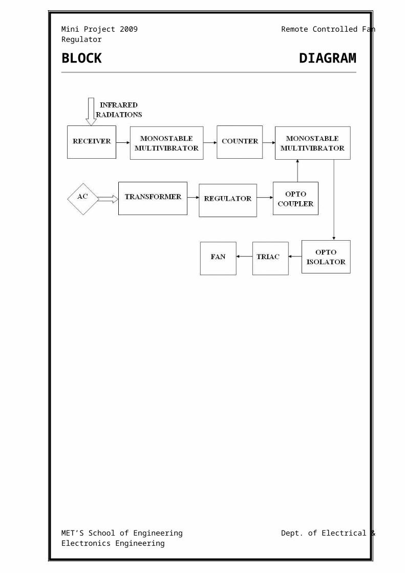
BLOCK DIAGRAM
MET’S School of Engineering Dept. of Electrical & Electronics Engineering

Mini Project 2009 Remote Controlled Fan Regulator
BLOCK DIAGRAM
DESCRIPTION
MET’S School of Engineering Dept. of Electrical & Electronics Engineering
Mini Project 2009 Remote Controlled Fan Regulator
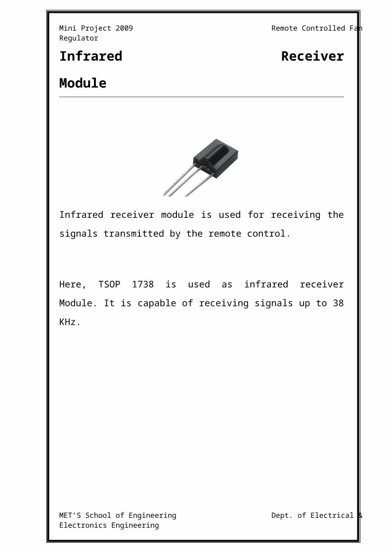
Infrared Receiver
Module
Infrared receiver module is used for receiving the signals transmitted by the
remote control.
Here, TSOP 1738 is used as infrared receiver Module. It is capable of
receiving signals up to 38 KHz.
MET’S School of Engineering Dept. of Electrical & Electronics Engineering
Mini Project 2009 Remote Controlled Fan Regulator
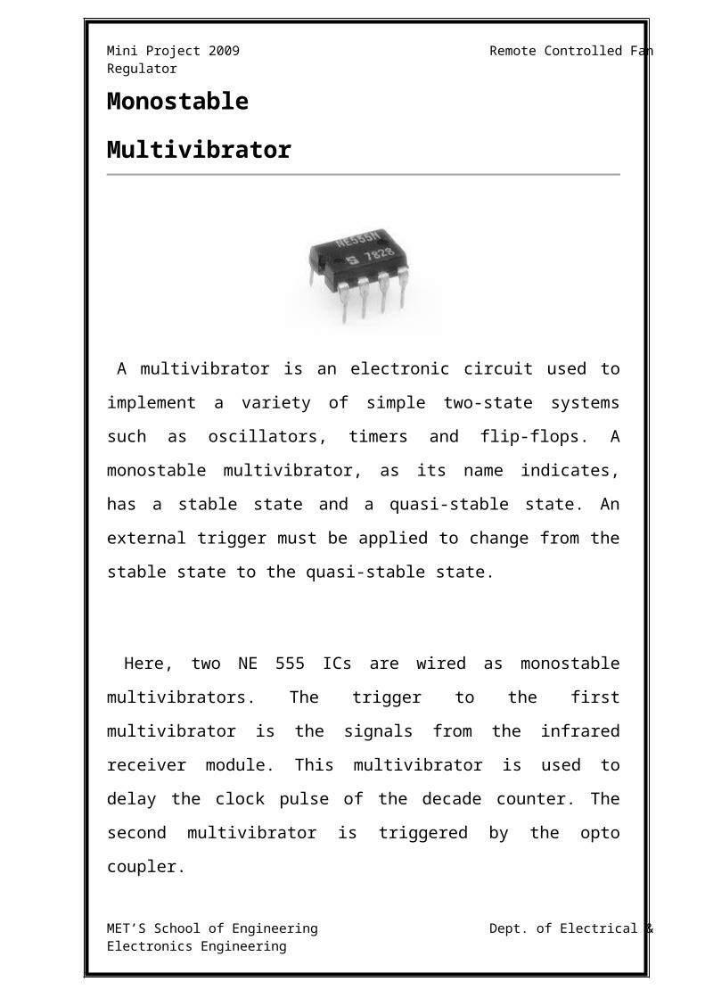
Monostable
Multivibrator
A multivibrator is an electronic circuit used to implement a variety of
simple two-state systems such as oscillators, timers and flip-flops. A
monostable multivibrator, as its name indicates, has a stable state and a
quasi-stable state. An external trigger must be applied to change from the
stable state to the quasi-stable state.
Here, two NE 555 ICs are wired as monostable multivibrators. The trigger
to the first multivibrator is the signals from the infrared receiver module.
This multivibrator is used to delay the clock pulse of the decade counter. The
second multivibrator is triggered by the opto coupler.
MET’S School of Engineering Dept. of Electrical & Electronics Engineering
Mini Project 2009 Remote Controlled Fan Regulator
Decade
Counter
In digital logic and computing, a counter is a device which stores (and
sometimes displays) the number of times a particular event or process has
occurred, often in relationship to a clock signal. Decade counter is a counter
that counts through 10 states. It is also known as a mod-10 counter.
Here, CD 4017 is used as decade counter. Here actually ten outputs are there
from which five are used (Q0 to Q4), Q5 is not used and Q6 is used to reset.
The output of monostable multivibrator(IC1) is used to delay the clock pulse
of the decade counter.
MET’S School of Engineering Dept. of Electrical & Electronics Engineering
Mini Project 2009 Remote Controlled Fan Regulator
Transformer
A transformer is a device that transfers electrical energy from one circuit to
another through inductively coupled conductors — the transformer's coils or
"windings". Transformer is used here to step down the supply voltage to a
level suitable for the low voltage components.
The transformer used here is a 230/(12V-0-12V) step down transformer.
MET’S School of Engineering Dept. of Electrical & Electronics Engineering
Mini Project 2009 Remote Controlled Fan Regulator
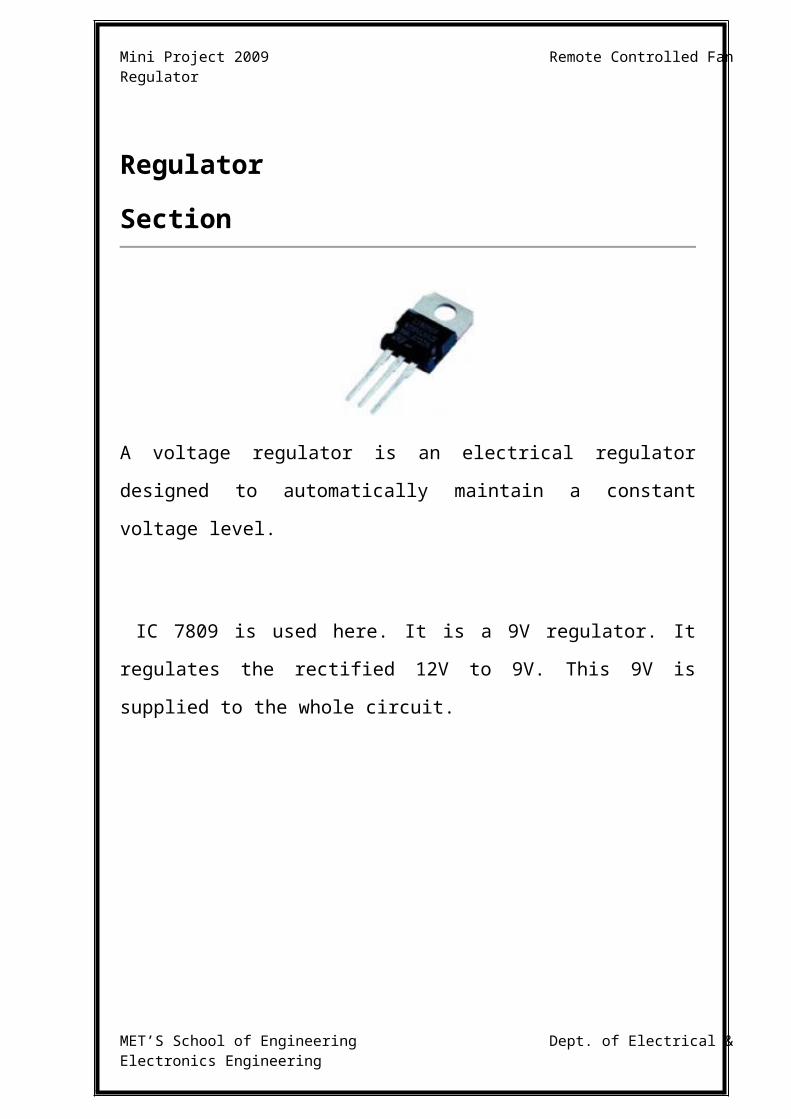
Regulator
Section
A voltage regulator is an electrical regulator designed to automatically
maintain a constant voltage level.
IC 7809 is used here. It is a 9V regulator. It regulates the rectified 12V to
9V. This 9V is supplied to the whole circuit.
MET’S School of Engineering Dept. of Electrical & Electronics Engineering
Mini Project 2009 Remote Controlled Fan Regulator
Opto Coupler
An Opto coupler is used to transmit either analog or digital information from
one voltage potential to another while maintaining isolation of potentials. It
is used for low voltages.
MCT2E is the opto coupler used here. MCT2E is NPN silicon planar
phototransistor optically coupled to a gallium arsenide infrared emitting
diode. It is used to trigger the monostable multivibrator(IC3).
MET’S School of Engineering Dept. of Electrical & Electronics Engineering

Mini Project 2009 Remote Controlled Fan Regulator
Opto Isolator
An Opto isolator is used to transmit either analog or digital information
from one voltage potential to another while maintaining isolation of the
potentials. Its operating voltage is higher than that of an Opto coupler.
Here, MOC3021 is used as opto isolator. It is used to drive the Triac BT136.
MET’S School of Engineering Dept. of Electrical & Electronics Engineering

Mini Project 2009 Remote Controlled Fan Regulator
Triac BT 136
A TRIAC, or TRIode for Alternating Current is an electronic component
approximately equivalent to two silicon-controlled rectifiers
(SCRs/thyristors) joined in inverse parallel (paralleled but with the polarity
reversed) and with their gates connected together. The formal name for a
TRIAC is bidirectional triode thyristor. This results in a bidirectional
electronic switch which can conduct current in either direction when it is
triggered (turned on) and thus doesn't have any polarity. It can be triggered
by either a positive or a negative voltage being applied to its gate electrode
(with respect to A1, otherwise known as MT1). Once triggered, the device
continues to conduct until the current through it drops below a certain
threshold value, the holding current, such as at the end of a half-cycle of
alternating current (AC) mains power. In addition, applying a trigger pulse at
a controllable point in an AC cycle allows one to control the percentage of
current that flows through the TRIAC to the load (phase control).
The triac used here is BT136. It is thyristor with a firing angle nearly 45o. A
snubber circuit consisting of a resistor and capacitor is used to control the
firing angle of Triac. This firing angle determines the speed of the fan.
MET’S School of Engineering Dept. of Electrical & Electronics Engineering
Mini Project 2009 Remote Controlled Fan Regulator
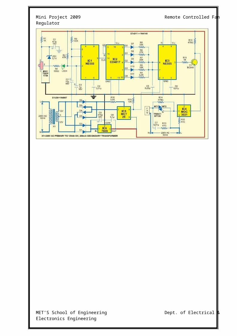
CIRCUIT DIADGRAM
MET’S School of Engineering Dept. of Electrical & Electronics Engineering

Mini Project 2009 Remote Controlled Fan Regulator
WORKING OF THE CIRCUIT
The 230 V from AC mains is stepped down to 12V and Regulated by
IC7809, capacitor and Diodes to 9V. This filtered 9V is used for providing
supply to the entire circuit. Any button of remote control can be used to
control the speed of the fan. The remote control produces infrared rays
which is received by the TSOP infrared receives module. The TSOP used
here is TSOP 1738. It is capable for receiving signals up to 38 KHZ. The
infrared rays are received by the TSOP sensor and its output is given as a
trigger to the first monostable multivibrator NE 555 through a LED and
Resistor R4.
This NE555 which is wired as Monostable multivibrator is used to delay the
clock to decade counter CD 4017. We can directly give the output of TSOP
to decade counter, but while doing so all the small pulse or noises may also
act as clock to counter and counter starts counting. The decade counter has
ten outputs from Q0 to Q9. But here we are using only Q0 to Q4. Q5 is not
used and Q6 is used to reset the counter. The output of decade counter is
taken through Resistors R5 to R9. The resistor R5 to R9 and capacitor C5
controls the pulse width which is actually determining the speed of the fan. If
the Q0 output is high the capacitor C5 is charged through R5, if Q1 is high
capacitor C5 is charged through R6 and so on, thereby controlling the speed
of the fan accordingly. Here we are controlling the speed of the fan in five
levels that is why we are taking five outputs (A0 to Q4).
Another NE 555 is used here which is also wired as monostable
multivibrator. This monostable multivibrator is triggered by pulses from opto
MET’S School of Engineering Dept. of Electrical & Electronics Engineering
Mini Project 2009 Remote Controlled Fan Regulator
coupler MCT2E. It is wired as Zero crossing detector. The output from
decade counter is given to NE555 and this is given to the transistor BC548.
It is given to the Opto isolator MOC 3021. It is used for driving the Triac
BT136. Triac is a type of thyristor. Here the resistor R13 (470hm) and
capacitor C7 (0.01µF) combination is used as snubber network for the Triac.
The Resistors R5 to R9 and capacitor C5 are used to control the pulse width.
When Q0 output is high the pulse width is maximum, when Q1 output is
high pulse width is decreased slightly. As the pulse width decreases firing
angle of the triac increases and speed of the fan also increases. By using
remote control we are actually controlling pulse width, which in turn varies
the firing angle of triac, and there by varying the speed of the fan.
MET’S School of Engineering Dept. of Electrical & Electronics Engineering
Mini Project 2009 Remote Controlled Fan Regulator
COMPONENTS LIST
1. IR Receiver Module - TSOP 1738
2. IC NE555
3. Opto Coupler - IC MCT2E
4. Opto Isolator - IC MOC 3021
5. Voltage Regulator - IC 7809
6. Decade Counter - IC CD4017
7. Transformer – 230/(12V -0-12V)
8. Light Emitting Diode
9. Diodes - IN4148, IN 4007
10. Transistor - BC548
11. Triac - BT136
12. Resistors - 1K, 100K, 330Ω, 47K Ω, 33K, 27K, 20K,
12K, 3.3K, 470 Ω, 5.6 K, 10 K, 47 Ω
13. Capacitors - 0.01 µF /400V, 4.7 µF /16V, 10 µF /16V,
1 µF /16V, 0.22µF, 470 µ /50V
14. Zener Diode - 5.1V
MET’S School of Engineering Dept. of Electrical & Electronics Engineering
Mini Project 2009 Remote Controlled Fan Regulator
PCB FABRICATION
Printed Circuit Boards play a vital role here in determining the overall
performance of the electronic equipment. A good PCB design ensures that
the noise introduced as a result of component placement and track layout is
held within limits while still providing components years of assembly
maintenance and performance reliability.
WHERE AND WHY ARE PCB’S USED?
Printed circuits boards are used to route electric signals through copper track
which are firmly bonded to an insulating base.
Advantages of PCB over common wiring are:
1. PCB’s are necessary for connecting a large number of electronic
components in a very small area with minimum parasitic effects.
2. PCB’s are simulated with mass production with less chance of writing
error.
3. Small components are easily mounted.
4. Servicing in simplified.
The base materials used for PCB’s are glass epoxy, epoxy paper, polyester
etc. Copper foil used for copper clad is manufactured by the process of
electronic deposition.
MET’S School of Engineering Dept. of Electrical & Electronics Engineering
Mini Project 2009 Remote Controlled Fan Regulator
The properties of copper foil are:
Thickness………………35μ meter
Thickness tolerance……+5 μ meter
Purity of Copper………99.8%
Resistivity at 20oC…….0.1594
PREPARATION OF SINGLE SIDED PCB
In a single sided PCB the conductor tracks run only on one side of copper
clad board. Thus crossing of conductors is not allowed. Base materials are
selected according to application. It is mechanically and chemically
cleansed. The photo resist is an organic solution which when exposed to
light of proper wavelength, changes their solubility in developer but after
exposure to light is not soluble. Laminate coating of photo resist is done by
(i) Spray coating
(ii) Dip coating
(iii) Roller coating.
The coated copper clad and laminated film negative is kept in intimate
contact with each other.
The assembly is exposed to UV light and is rinsed in the developer tank.
Proper developer has to be used for a particular photo resist and then the
PCB is dyed in a tray. The dye reveals the flux to be used for a particular
photo resist. Then the PCB is dyed in a tray.
MET’S School of Engineering Dept. of Electrical & Electronics Engineering
Mini Project 2009 Remote Controlled Fan Regulator
LAYOUT
The layout can be done either by hand or by using PCB designing software
like ORCAD or PROTEL.
FABRICATION
The required circuit is designed and the layout of the circuit is done on the
component side as well as the copper clad side. Spaces are provided for
holes to insert the respective components. Etch resistant ink coatings are
given on the interconnecting marks.
ETCHING
The copper clad PCB is etched with ferrous chloride solution containing a
small amount of Hydro Chloric Acid for increasing activeness of Ferric
Chloride in etching. Wherever the varnish coating is there the copper
remains. Then it is washed with water and Oxalic Acid.
DRILLING
The required holes of suitable size are drilled using twist drill. Now the
Printed Circuit Board(PCB) is complete and ready for soldering.
MET’S School of Engineering Dept. of Electrical & Electronics Engineering

Mini Project 2009 Remote Controlled Fan Regulator
SOLDERING
Soldering is the process of joining of two metals using an alloy solder
consisting of Tin and Lead (Sn-Pb). Tin determines the melting whereas the
Lead is used to reduce the cost. After the PCB fabrication is done, the
various components are arranged at proper locations on the PCB and then the
soldering is done. All liquids consist of particles which attract each other.
The surface is always trying to shrink and this is because of surface tension.
The principle behind soldering is that when liquid particles are brought in
contact with the walls of the solid surface, it may happen that the solid
attracts the liquid surface. This property is called adhesive property. Care
must be taken that the melting point of solder is below that of the metal so
that its surface is melted without melting without the metal.
NEED FOR FLUX
During the soldering process the flux acts as a medium for improving the
degree of melting. The basic functions of flux are mentioned below:
1. Removes oxide from the surface.
2. Assists the transfer of heat from the source to the joining and provides
a liquid cover including air gap.
3. Removal of residue after the completion of the soldering operation.
MET’S School of Engineering Dept. of Electrical & Electronics Engineering
Mini Project 2009 Remote Controlled Fan Regulator
PCB LAYOUT
MET’S School of Engineering Dept. of Electrical & Electronics Engineering
Mini Project 2009 Remote Controlled Fan Regulator
COMPONENT VIEW
MET’S School of Engineering Dept. of Electrical & Electronics Engineering
Mini Project 2009 Remote Controlled Fan Regulator
APPLICATION
Remote controlled Fan Regulator is used to control the speed of fan
from our bed or couch.
The same circuit finds its use to control the Intensity of light at various
levels.
This circuit also finds it use for switching ON and OFF any electronic
circuit.
MET’S School of Engineering Dept. of Electrical & Electronics Engineering

Mini Project 2009 Remote Controlled Fan Regulator
ADVANTAGES
This circuit is simple to use and efficient.
It can be assembled with ease.
It is cheap and hence very economic.
It is small in size.
MET’S School of Engineering Dept. of Electrical & Electronics Engineering

Mini Project 2009 Remote Controlled Fan Regulator
CONCLUSION
With the knowledge of new techniques in ‘Electronics’ we are able to make
our life more comfortable. One such application of electronics is used in
“REMOTE CONTROLLED FAN REGULATOR”.
The same circuit finds its use in many more applications. By this the
intensity of light can be controlled using a remote. The intensity of light can
be controlled in five levels from off position to maximum intensity possible.
So it finds use as a night lamp by keeping the intensity of lamp in low level.
The circuit also finds its use for switching ON and OFF any electronic
circuitry. Our normal T.V remote can be used for all these purposes. So it is
very useful or a real help to old age and sick people, since they can control
the speed from the place where they are sitting.
We feel that our product serves something good to this world and we like to
present it before this prosperous world.
MET’S School of Engineering Dept. of Electrical & Electronics Engineering
Mini Project 2009 Remote Controlled Fan Regulator
REFERENCE
www.electronicsforyou.com
www.howstuffworks.com
www.wikipedia.org
Electronics for You Magazine
Electronic Devices and Circuits – J. B.Gupta
Linear Integrated circuits – Gaykwad
MET’S School of Engineering Dept. of Electrical & Electronics Engineering
Related Documents