THE REMOTE CONTROL FREQUENCIES by Jean Marie POLA RD (Ternat, Belgium) At certain times of the day, one can detect on the electrical supp ly network the prese nce of signals whose frequency varies between 110Hz and 1600Hz. Th ey ar e use for control different load function as: stre et lig hting, tools and machines, water heating, special loads, shop windows, ventilations, stor age heather s, summoning assista nce, building lighting, pumping plants, domestic appliances, alert ing, tar iff changeover, air - condi tion ers and other special tasks. This article will give you a little more information about them and how they are displayed on a spectrogram. USED FREQUENCIES From the VDEW, which is the main German Electrici ty Company we have the followin g table about used frequencies : Frequence [Hz] Ban dspread [%] Ampli tude [%] 110 1,7 168 -0,5...+0,5 1,7 175 -0,5...+0,5 2,5 183,3 -2...+1 3 190 -0,5...+0,5 2,5 194 2 206 2 216,7 -2...+1 3 228 2 232 -0,5...+0,5 1,7 267 -0,5...+0,5 1,7 270 3 283,3 -2...+1 3 316,7 -2...+1 3 383,3 -2...+1 3 425 -2...+1 3 VLF OpenLab: REMOTE CONTROL FREQ. ht tp:// www.vlf.it/polard/rcf.ht m l 1 of 6 02/ 10/2011 11:35 SA

Welcome message from author
This document is posted to help you gain knowledge. Please leave a comment to let me know what you think about it! Share it to your friends and learn new things together.
Transcript
8/3/2019 REMOTE CONTROL FREQ
http://slidepdf.com/reader/full/remote-control-freq 1/6
THE REMOTE CONTROL FREQUENCIESby Jean Marie POLARD (Ternat, Belgium)
At certain times of the day, one can detect on the electrical supply network the presence of signals whose frequency varies between 110Hz and 1600Hz. They are use for control different load function as: street lighting, tools and machines, water heating, special loads, shop windows, ventilations, storage heathers, summoning assistance, building lighting, pumping plants, domestic appliances, alerting, tariff changeover, air - conditioners and other special tasks.
This article will give you a little more information about them and how they are displayed on a spectrogram.
USED FREQUENCIES
From the VDEW, which is the main German Electricity Company we have the following table about usedfrequencies :
Frequence [Hz] Bandspread [%] Amplitude [%]
110 1,7
168 -0,5...+0,5 1,7
175 -0,5...+0,5 2,5
183,3 -2...+1 3
190 -0,5...+0,5 2,5
194 2
206 2
216,7 -2...+1 3
228 2
232 -0,5...+0,5 1,7
267 -0,5...+0,5 1,7
270 3
283,3 -2...+1 3
316,7 -2...+1 3
383,3 -2...+1 3
425 -2...+1 3
OpenLab: REMOTE CONTROL FREQ. http://www.vlf.it/polard/rcf.html
6 02/10/2011 11:35 SA
8/3/2019 REMOTE CONTROL FREQ
http://slidepdf.com/reader/full/remote-control-freq 2/6
485 4
582 4
600 -2...+1 4
725 4
750 -2...+1 4
1050 -2...+1 3
1350 -2...+1 3
1600 -2...+1 2,5
The bandspread indicates the allowable variation of the transmitter frequency upward and downard inpercentage of their respective nominal frequency. The amplitude level is indicated in percent of the50-Hz-main voltage. The odd frequency data originates from the time, when the audio frequencyachievement was produced with mechanical converters. At this time, an engine activated an audiogenerator over the main wave. The number of pairs of poles of this generator amounts to a multipleopposite the propelling 50Hz machine. From that, the frequencies explain themselves as whole multiple,which were used before the introduction of the heavy current semiconductor technology. Thus e.g. agenerator for 500 cycles per second has 10 times the pair of poles of its propelling engine.
The driving motors are partly synchronous engines, partly synchronous motors. Synchronous enginesdue to their slip never reach the nominal frequency. Thus the produced audio frequency cannot reachtheir nominal value at such plants. It was usual with such plants to indicate not the nominal frequencybut the lowest frequency still permissible for the enterprise with a slip of 3%. Thus one spoke of thefrequencies e.g. 194, 485, 582 and 725 cycles per second. The always varying load of the generator ledalso to a varying slip of the synchronous engine and thus again to a varying transmitter frequency. Thisis also the reason, why couplings for these frequencies are arranged as broadband filters.
The PULSADIS system
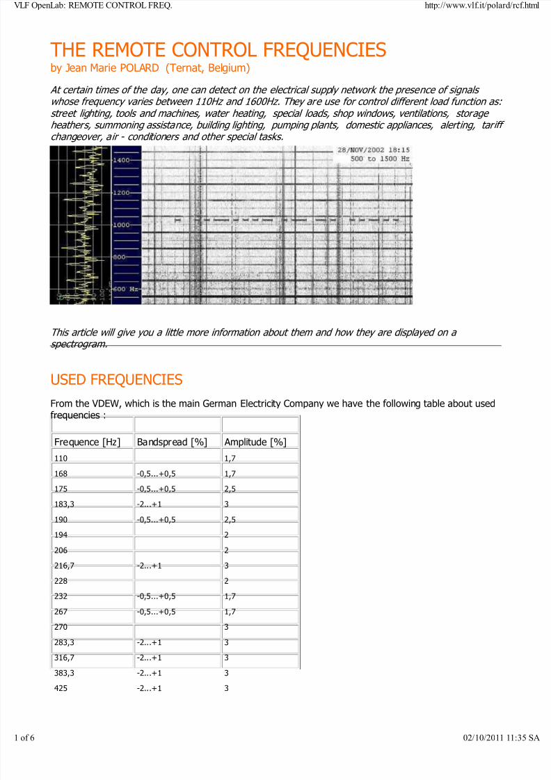
Since about thirty years, EDF (Electricité de France) uses a system of remote control called PULSADIS which makes it possible from the maidistribution centers to start the change of tariff of the meters at thewanted hour, and optionally of other services like the street lighting,This system is based on the injection on the mains of signals accordia code which the receivers recognize and which gives them the ordercarry out commutations corresponding to the signals that they aresupposed to recognize.
<< The relay actuated by the pulsadis system on an electric consumption counter
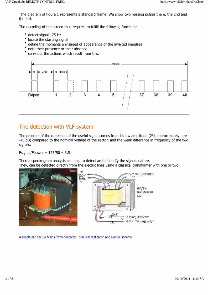
The carrying signal is to 175 Hz with an amplitude minimum of 0,9% of the nominal voltage of thesector, that is to say 2,3V.
It is modulated by binary impulses according to the following code: A signal of 1 second followed by a 2,75 seconds silence indicates the beginning of screen. The receiverrecognizes this signal and starts to count time from this moment. The frame comprises 40 impulses of 2,5 seconds and its total duration is 102,25 seconds.
Each frame of pulse is composed of one duration of 1 second during which there can be or not emissionof the 175 Hz carrier, and a 1,5 seconds silence being used as separator with the following frame. If the
signal is present, it starts in the receivers a swing. Another impulse is designed to produce the oppositeswing. If none of these two pulses are present, the receiver does not change its state. The pulses beingassociated per pairs (one starts, the other stops), 20 channels are available for all that types of differentremote controls.
OpenLab: REMOTE CONTROL FREQ. http://www.vlf.it/polard/rcf.html
6 02/10/2011 11:35 SA
8/3/2019 REMOTE CONTROL FREQ
http://slidepdf.com/reader/full/remote-control-freq 3/6
The diagram of figure 1 represents a standard frame. We show two missing pulses there, the 2nd andthe 4rd.
The decoding of the screen thus requires to fulfill the following functions:
detect signal 175 Hzlocate the starting signal
define the moments envisaged of appearance of the awaited impulses
note their presence or their absencecarry out the actions which result from this.
The detection with VLF system
The problem of the detection of the useful signal comes from its low amplitude (2% approximately, are-40 dB) compared to the nominal voltage of the sector, and the weak difference in frequency of the twosignals:
Fsignal/Fpower = 175/50 = 3,5
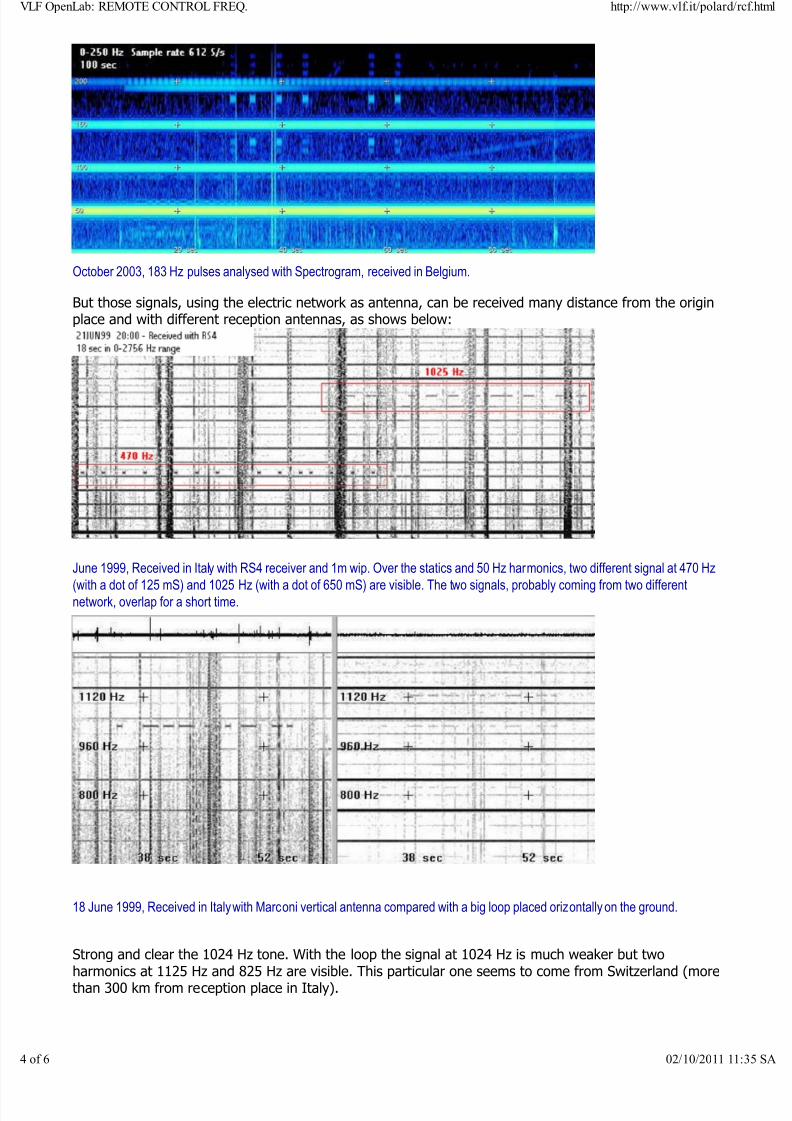
Then a spectrogram analysis can help to detect an to identify the signals nature.They, can be detected directly from the electric lines using a classical transformer with one or twocoupling coils.
A simple and secure Mains Power detector: practical realization and electric scheme
OpenLab: REMOTE CONTROL FREQ. http://www.vlf.it/polard/rcf.html
6 02/10/2011 11:35 SA
8/3/2019 REMOTE CONTROL FREQ
http://slidepdf.com/reader/full/remote-control-freq 4/6
8/3/2019 REMOTE CONTROL FREQ
http://slidepdf.com/reader/full/remote-control-freq 5/6
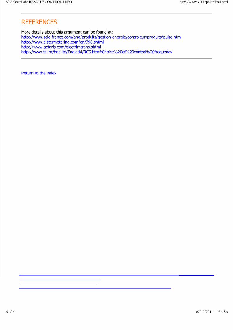
15 July 1999, 20:00 Marconi antenna compares with signals received with a transformer on the electric line.
'On air' the signal at 1025 is not present, low harmonics of 50 Hz and good sferics are seen. On themains the sferics are not present, harmonics are strong and the binary signal is clear with image at1125 Hz. The result is different at different time: two hours before the situation at 1025 Hz wasopposite.
Injection of signal on the mains and emissions control
A typical structure of one ripple control system consists of a control programming unit, remote controlfacilities between control centre and substations and many receivers in the low - voltage distributionnetwork.
Here below an example with a Trasmitter, a serial coupling and an "home receiver"
The signal injection levels usually takes place at the medium - voltage level (10, 20 or 35 kV)symmetrically, in all three phases, so that propagation can penetrate right down to the low voltage level.But it can operate at any voltage level between 0,4 and 110 kV. The choice of injection level dependsmainly on the size of the network to be controlled as well as the type of network ( rural or municipal ).
System can be designed for parallel or series injection of audio frequency in the network. In the case of parallel injection, impedances of high voltage network and that of power transformer are in parallel withimpedances of the network to be controlled. When series injection is applied, the both networks areconnected in series and impedances of the power transformer and high voltage network must be muchlower than that of the network to be controlled.
Here beside a "PULSE TRACKER" device, used for network maintenance and control. . Itenables supervision and analysis of the telegrams quality from 160 to 500 Hz (Pulsadis40/50, Semagyr 50a/50b/52/56, Versacom or Customized) either locally or from a
distant location.This device records and analyses all characteristics: rate, offset, width and interferingpulses and enables detailed recording of 175Hz telegrams corresponding to the pre-set.tariffs. It enables setting detection and supervision thresholds locally or remotely ansidentifies the different faults for each single order.
OpenLab: REMOTE CONTROL FREQ. http://www.vlf.it/polard/rcf.html
6 02/10/2011 11:35 SA
8/3/2019 REMOTE CONTROL FREQ
http://slidepdf.com/reader/full/remote-control-freq 6/6
REFERENCES
More details about this argument can be found at:http://www.scle-france.com/ang/produits/gestion-energie/controleur/produits/pulse.htmhttp://www.elstermetering.com/en/796.shtmlhttp://www.actaris.com/elect/lmtrans.shtmlhttp://www.tel.hr/hdc-itd/Engleski/RCS.htm#Choice%20of%20control%20frequency
Return to the index
OpenLab: REMOTE CONTROL FREQ. http://www.vlf.it/polard/rcf.html
Related Documents