RELIABLE CONNECTION TECHNOLOGY WITHOUT COMPROMISES STRAUB PIPE COUPLINGS STRAUB Manual

Welcome message from author
This document is posted to help you gain knowledge. Please leave a comment to let me know what you think about it! Share it to your friends and learn new things together.
Transcript
RELIABLE CONNECTION TECHNOLOGY
WITHOUT COMPROMISES
STRAUB PIPE COUPLINGSSTRAUB Manual

Version 18 °03
50 YEARS STRAUB 4
FEATURES AND BENEFITS 6
THE PRINCIPLE 8
TECHNICAL PROPERTIES 9
STRAUB PIPE COUPLINGS - AXIAL RESTRAINT
STRAUB-METAL-GRIP 16
STRAUB-GRIP 16
STRAUB-FIRE-FENCE 17
STRAUB-ECO-GRIP 26
STRAUB-COMBI-GRIP 28
STRAUB-PLAST-GRIP 28
FITTING INSTRUCTION STRAUB-GRIP 32
STRAUB-PLAST-PRO | DIN + MULTILAYER 34
STRAUB PIPE COUPLINGS - NON-AXIAL RESTRAINT
SPECIFICATION 50
STRAUB-FLEX 51
STRAUB-OPEN-FLEX (GT) 57
STRAUB-OPEN-FLEX-FIRE-FENCE 66
STRAUB-STEP-FLEX 69
STRAUB-SQUARE-FLEX 72
STRAUB REPAIR PRODUCTS
STRAUB-REP-FLEX 75
STRAUB-CLAMP 78
STRAUB SHAPED PARTS 81
ACCESSORIES 86
STRAUB LABEL 94
INSTALLATION INSTRUCTIONS 95
PIPE DIMENSIONS TABLE 103
PIPE GAP 104
DIMENSIONS AND WALL THICKNESS 105
ASSEMBLY SET-UP TIME 106
MATERIAL SPECIFICATIONS 107
CORROSION PROTECTION 108
SHIPBUILDING 111
USE IN SHIPBUILDING 114
STRAUB FIRE PROTECTION SYSTEM 115
ADVANTAGES FOR SHIPBUILDING 116
SHIPBUILDING REFERENCES 118
APPROVALS 120
WORLDWIDE BRANCH OFFICES 123
TECHNICAL SHORT CHECK LIST 124
GTC general terms and conditions 126
CONTENTS
4
50 YEARS
STRAUB PIPE COUPLINGS
«Develop a new, good idea and
implement it consistently in a new, good product»
Immanuel Straub
STRAUB Werke AG celebrated its 50th anniversary in 2017. What start-ed in 1967 with the invention of the STRAUB pipe connection is a global successful brand today.
“The STRAUB pipe connection is not an accidental invention but the result of systematic study of the problem.”
There were always numerous possibili ties for connecting pipes. That require a lot of special know-ledge paired with keeping extensive stock.
Immanuel Straub set himself the objective of bringing order to this “clutter”. During this research and development work, he found a uni-versal pipe connection concept that
can be applied very easily and very quickly, nevertheless provides the greatest reliability: the STRAUB pipe connection!
This innovative solution permanent-ly revolutionised pipe connection technology. The quick, easy and reliable “straubING” took the place of welding or flange connections.
Thanks to its ingenious concept, the original STRAUB coupling is regard-ed as one of the best innovations in the global market of pipe connect–ion technology.
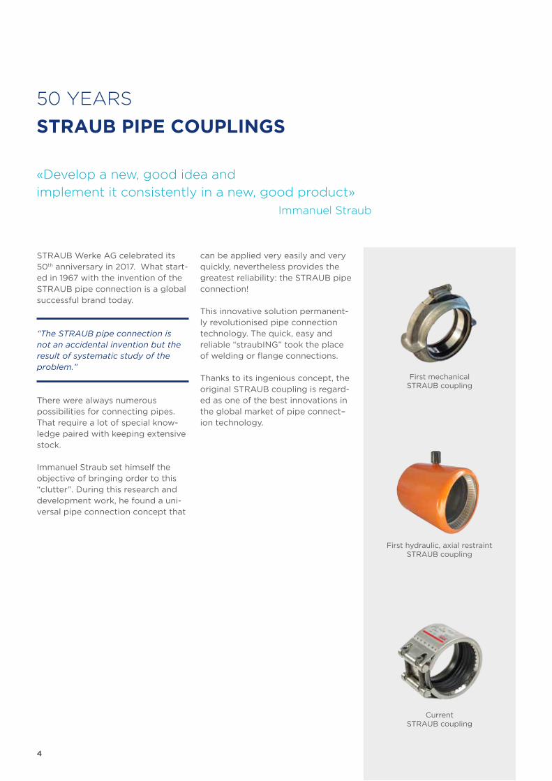
First mechanical STRAUB coupling
First hydraulic, axial restraint STRAUB coupling
Current STRAUB coupling

5
Immanuel Straub:«To concentrate and commit where you can
do more than others is another maxim!»
6
COMPATIBILITY STOCK REDUCTION
SYSTEM INDEPENDENCE FREE CHOICE OF PIPE SUPPLIER
RELIABILITY REDUCTION OF REWORK
EFFICIENCY RAPID INSTALLATION TIMES
SAFETY PERSONAL AND ENVIRONMENTAL PROTECTION
SERVICE MANUFACTURER’S TECHNICAL SUPPORT
QUALITY CONSISTENT QUALITY ASSURED
OUR PERFORMANCE YOUR ADVANTAGE
THE STRAUB 5-YEAR GUARANTEE!
7
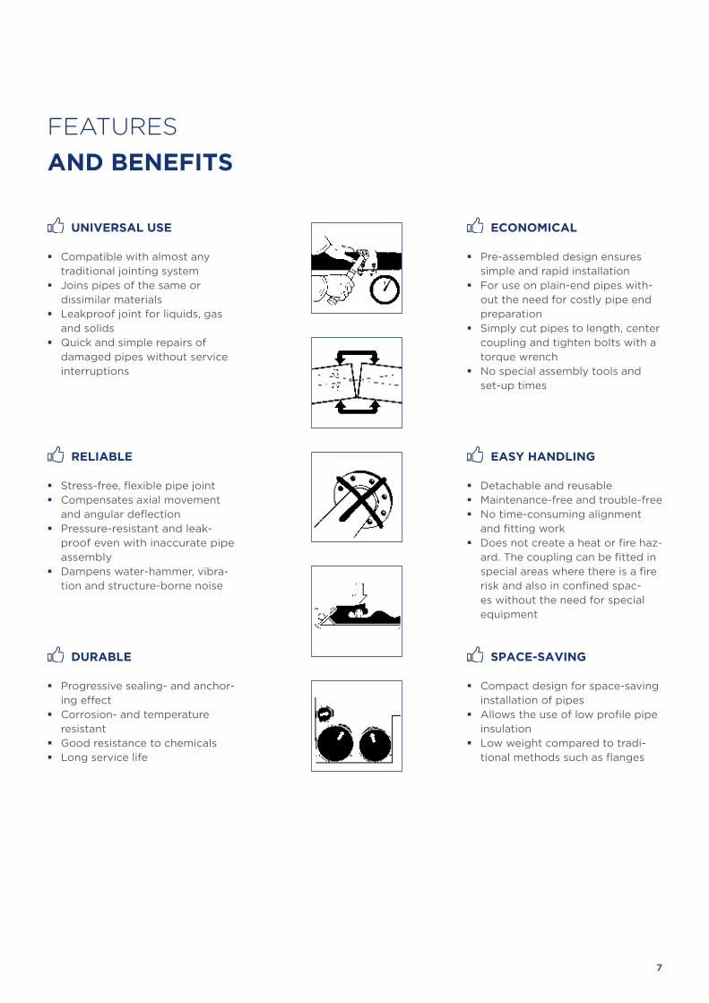
ECONOMICAL
� Pre-assembled design ensures simple and rapid installation
� For use on plain-end pipes with-out the need for costly pipe end preparation
� Simply cut pipes to length, center coupling and tighten bolts with a torque wrench
� No special assembly tools and set-up times
EASY HANDLING
� Detachable and reusable � Maintenance-free and trouble-free � No time-consuming alignment
and fitting work � Does not create a heat or fire haz-
ard. The coupling can be fitted in special areas where there is a fire risk and also in confined spac-es without the need for special equipment
SPACE-SAVING
� Compact design for space-saving installation of pipes
� Allows the use of low profile pipe insulation
� Low weight compared to tradi-tional methods such as flanges
UNIVERSAL USE
� Compatible with almost any traditional jointing system
� Joins pipes of the same or dissimilar materials
� Leakproof joint for liquids, gas and solids
� Quick and simple repairs of damaged pipes without service interruptions
RELIABLE
� Stress-free, flexible pipe joint � Compensates axial movement
and angular deflection � Pressure-resistant and leak-
proof even with inaccurate pipe assembly
� Dampens water-hammer, vibra-tion and structure-borne noise
DURABLE
� Progressive sealing- and anchor-ing effect
� Corrosion- and temperature resistant
� Good resistance to chemicals � Long service life
FEATURES
AND BENEFITS
8
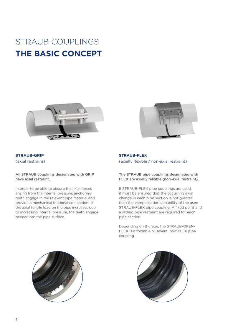
STRAUB COUPLINGS
THE BASIC CONCEPT
All STRAUB couplings designated with GRIP have axial restraint.
In order to be able to absorb the axial forces arising from the internal pressure, anchoring teeth engage in the relevant pipe material and provide a mechanical frictional connection. If the axial tensile load on the pipe increases due to increasing internal pressure, the teeth engage deeper into the pipe surface.
The STRAUB pipe couplings designated with FLEX are axially felxible (non-axial restraint).
If STRAUB-FLEX pipe couplings are used, it must be ensured that the occurring axial change in each pipe section is not greater than the compensation capability of the used STRAUB-FLEX pipe coupling. A fixed point and a sliding pipe restraint are required for each pipe section.
Depending on the size, the STRAUB-OPEN-FLEX is a foldable or several part FLEX pipe coupling.
STRAUB-GRIP
(axial restraint)
STRAUB-FLEX
(axially flexible / non-axial restraint)
9
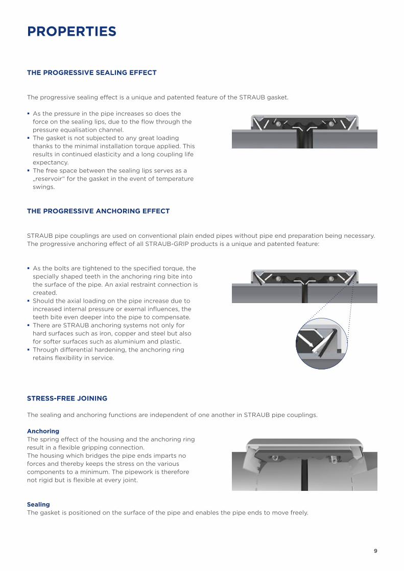
The progressive sealing effect is a unique and patented feature of the STRAUB gasket.
� As the pressure in the pipe increases so does the force on the sealing lips, due to the flow through the pressure equalisation channel.
� The gasket is not subjected to any great loading thanks to the minimal installation torque applied. This results in continued elasticity and a long coupling life expectancy.
� The free space between the sealing lips serves as a „reservoir“ for the gasket in the event of temperature swings.
STRAUB pipe couplings are used on conventional plain ended pipes without pipe end preparation being necessary. The progressive anchoring effect of all STRAUB-GRIP products is a unique and patented feature:
� As the bolts are tightened to the specified torque, the specially shaped teeth in the anchoring ring bite into the surface of the pipe. An axial restraint connection is created.
� Should the axial loading on the pipe increase due to increased internal pressure or exernal influences, the teeth bite even deeper into the pipe to compensate.
� There are STRAUB anchoring systems not only for hard surfaces such as iron, copper and steel but also for softer surfaces such as aluminium and plastic.
� Through differential hardening, the anchoring ring retains flexibility in service.
THE PROGRESSIVE SEALING EFFECT
THE PROGRESSIVE ANCHORING EFFECT
The sealing and anchoring functions are independent of one another in STRAUB pipe couplings.
SealingThe gasket is positioned on the surface of the pipe and enables the pipe ends to move freely.
STRESS-FREE JOINING
AnchoringThe spring effect of the housing and the anchoring ring result in a flexible gripping connection.The housing which bridges the pipe ends imparts no forces and thereby keeps the stress on the various comp onents to a minimum. The pipework is therefore not rigid but is flexible at every joint.
PROPERTIES
10
STRAUB-FLEX
15
10
5
0
-5
-10
-15
-20
8 16 31.5 63 125 250 500 1K
[db]
[Hz]
STRAUB-GRIP
STRAUB-FLEX
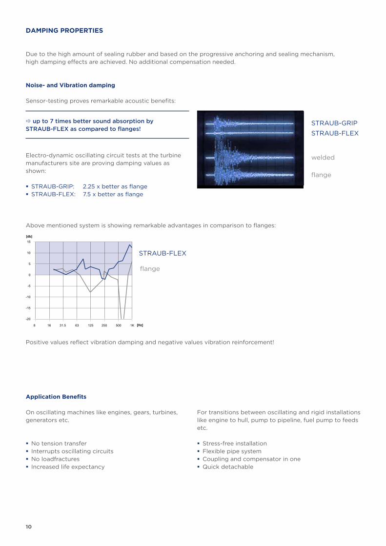
DAMPING PROPERTIES
Due to the high amount of sealing rubber and based on the progressive anchoring and sealing mechanism, high damping effects are achieved. No additional compensation needed.
Noise- and Vibration damping
Sensor-testing proves remarkable acoustic benefits:
Application Benefits
welded
flange
Electro-dynamic oscillating circuit tests at the turbine manufacturers site are proving damping values as shown:
� STRAUB-GRIP: 2.25 x better as flange � STRAUB-FLEX: 7.5 x better as flange
Above mentioned system is showing remarkable advantages in comparison to flanges:
Positive values reflect vibration damping and negative values vibration reinforcement!
flange
up to 7 times better sound absorption by STRAUB-FLEX as compared to flanges!
On oscillating machines like engines, gears, turbines, generators etc.
� No tension transfer � Interrupts oscillating circuits � No loadfractures � Increased life expectancy
For transitions between oscillating and rigid installations like engine to hull, pump to pipeline, fuel pump to feeds etc.
� Stress-free installation � Flexible pipe system � Coupling and compensator in one � Quick detachable
11
60
50
40
30
20
10
0
0 0.01 0.02 0.03 0.04 0.05 0.06
Druck [bar]
Zeit [Sekunden]
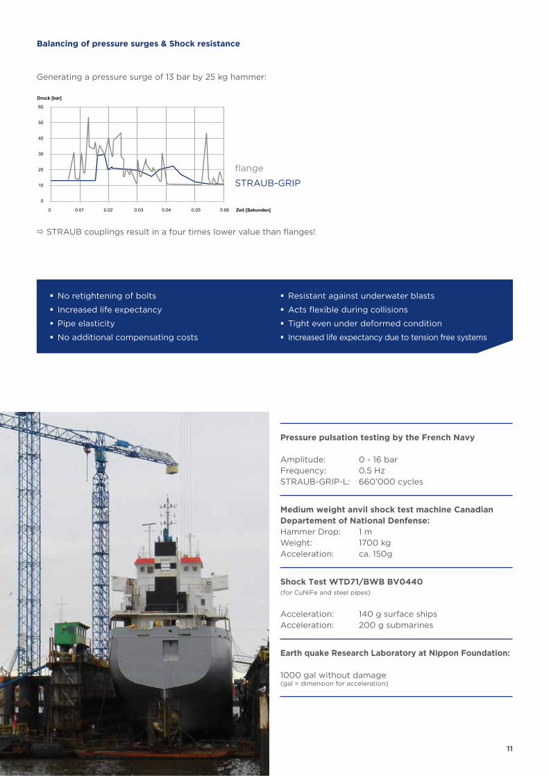
STRAUB-GRIP
Generating a pressure surge of 13 bar by 25 kg hammer:
Pressure pulsation testing by the French Navy
Amplitude: 0 - 16 barFrequency: 0.5 HzSTRAUB-GRIP-L: 660’000 cycles
Medium weight anvil shock test machine Canadian Departement of National Denfense:Hammer Drop: 1 mWeight: 1700 kgAcceleration: ca. 150g
Balancing of pressure surges & Shock resistance
Earth quake Research Laboratory at Nippon Foundation:
1000 gal without damage (gal = dimension for acceleration)
Shock Test WTD71/BWB BV0440(for CuNiFe and steel pipes)
Acceleration: 140 g surface shipsAcceleration: 200 g submarines
� No retightening of bolts
� Increased life expectancy
� Pipe elasticity
� No additional compensating costs
� Resistant against underwater blasts
� Acts flexible during collisions
� Tight even under deformed condition
� Increased life expectancy due to tension free systems
STRAUB couplings result in a four times lower value than flanges!
flange
12
The life expectancy of STRAUB pipe joints and STRAUB repair clamps fitted with sealing sleeves made of EPDM, NBR or FKM/FPM extend to 25 year or more, provided that recommended storage procedures are correctly adhered to.
Storage
Recommended long term storage conditions:
� Avoid exposure to direct sunlight by storing inside � Store at consistent temperatures (maximum 40°C/104°F) � The relative humidity should be kept above 50 % � Protect from dirt or soiling
Application conditions
Increased temperatureThe max. application temperature of EPDM is 125°C/250°F and NBR 100°C/230°F, but as a consequence the life span can be reduced. In addition dynamical and chemical stress has to be taken into consideration. For different applications please verify the life expectancy with the manu-facturer.
Low temperature:Subject to performance requirements the elasticity of STRAUB sealing sleeves is sufficient to cope with temperatures down to -30°C/-22°F. There is a loss of elasticity below this point which, under the stress of additional dynamic loading, can result in disruption of the elastomer.
The coupling casing and the anchoring ring (GRIP) completely enclose the sealing sleeve and therefore protect it from UV irradiation.
Because of their progressive sealing effect, STRAUB sealing sleeves require a smaller tightening force and therefore subjected to less stress than, say, a flange seal. The elasticity and hence the working life of STRAUB sealing sleeves is consquently maintained over a longer period.
LIFE EXPECTANCY
13
THE STRAUB
MAIN RANGE OF APPLICATION
The installation of a STRAUB pipe joint is fast, simple and reliable - even under the most demanding circumstances, anywhere in the world is the STRAUB philosophy.
The STRAUB applications and opportunities:
Sanitary linesFire fighting linesVentilation lines
Cooling linesLubrication lines
Utility linesFuel lines
Penstock linesTurbine lines
Transport lines
Water lines Gas lines
Wells Hydrant lines
Tank lines Sludge lines
Drainage linesChemical lines Airation lines
Fire fighting linesVent lines
Sea water cooling systemsBallast linesFuel lines
GR
OU
ND
WO
RK
& I
ND
US
TR
Y
SH
IPB
UIL
DIN
G &
OF
FS
HO
RE
WA
TE
R &
GA
S
14
EL
EM
EN
TA
RY
FO
RC
ES
RE
LIA
BL
Y U
ND
ER
CO
NT
RO
L
15
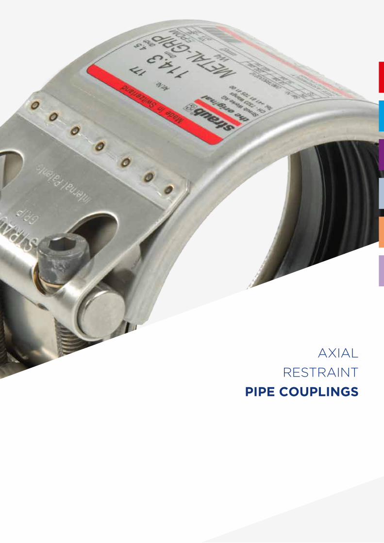
AXIAL
RESTRAINT
PIPE COUPLINGS
16
STRAUB-METAL-GRIP STRAUB-GRIP
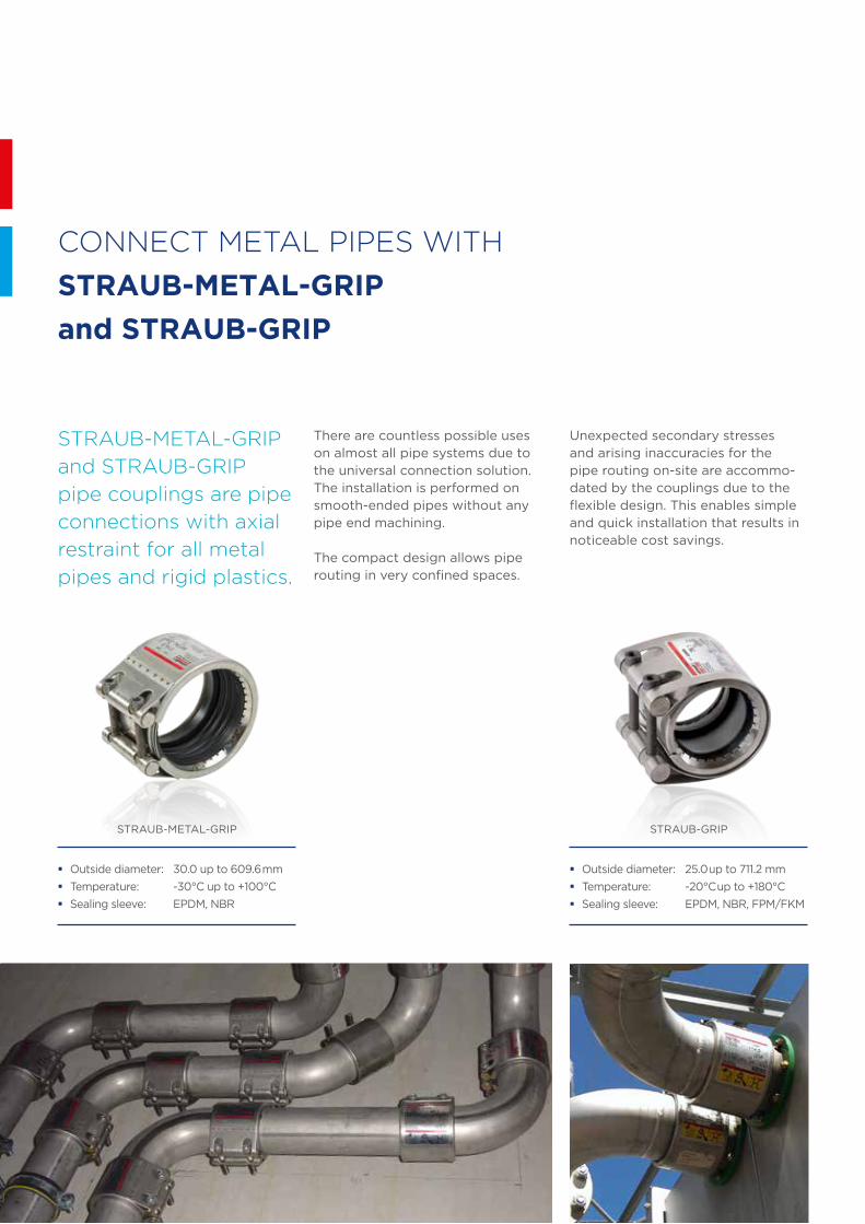
CONNECT METAL PIPES WITH
STRAUB-METAL-GRIP
and STRAUB-GRIP
STRAUB-METAL-GRIP
and STRAUB-GRIP
pipe couplings are pipe
connections with axial
restraint for all metal
pipes and rigid plastics.
There are countless possible uses on almost all pipe systems due to the universal connection solution. The installation is performed on smooth-ended pipes without any pipe end machining.
The compact design allows pipe routing in very confined spaces.
Unexpected secondary stresses and arising inaccuracies for the pipe routing on-site are accommo-dated by the couplings due to the flexible design. This enables simple and quick installation that results in noticeable cost savings.
� Outside diameter: 30.0 up to 609.6 mm
� Temperature: -30°C up to +100°C
� Sealing sleeve: EPDM, NBR
� Outside diameter: 25.0 up to 711.2 mm
� Temperature: -20°C up to +180°C
� Sealing sleeve: EPDM, NBR, FPM/FKM
17
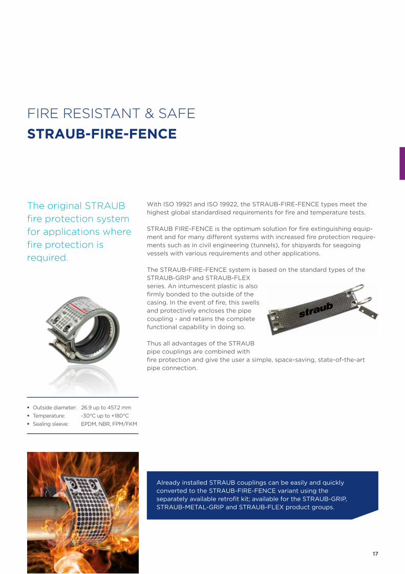
FIRE RESISTANT & SAFE
STRAUB-FIRE-FENCE
With ISO 19921 and ISO 19922, the STRAUB-FIRE-FENCE types meet the highest global standardised requirements for fire and temperature tests.
STRAUB FIRE-FENCE is the optimum solution for fire extinguishing equip-ment and for many different systems with increased fire protection require-ments such as in civil engineering (tunnels), for shipyards for seagoing vessels with various requirements and other applications.
The STRAUB-FIRE-FENCE system is based on the standard types of the STRAUB-GRIP and STRAUB-FLEX series. An intumescent plastic is also firmly bonded to the outside of the casing. In the event of fire, this swells and protectively encloses the pipe coupling - and retains the complete functional capability in doing so.
Thus all advantages of the STRAUB pipe couplings are combined with fire protection and give the user a simple, space-saving, state-of-the-art pipe connection.
The original STRAUB
fire protection system
for applications where
fire protection is
required.
Already installed STRAUB couplings can be easily and quickly converted to the STRAUB-FIRE-FENCE variant using the separately available retrofit kit; available for the STRAUB-GRIP, STRAUB-METAL-GRIP and STRAUB-FLEX product groups.
� Outside diameter: 26.9 up to 457.2 mm
� Temperature: -30°C up to +180°C
� Sealing sleeve: EPDM, NBR, FPM/FKM
18
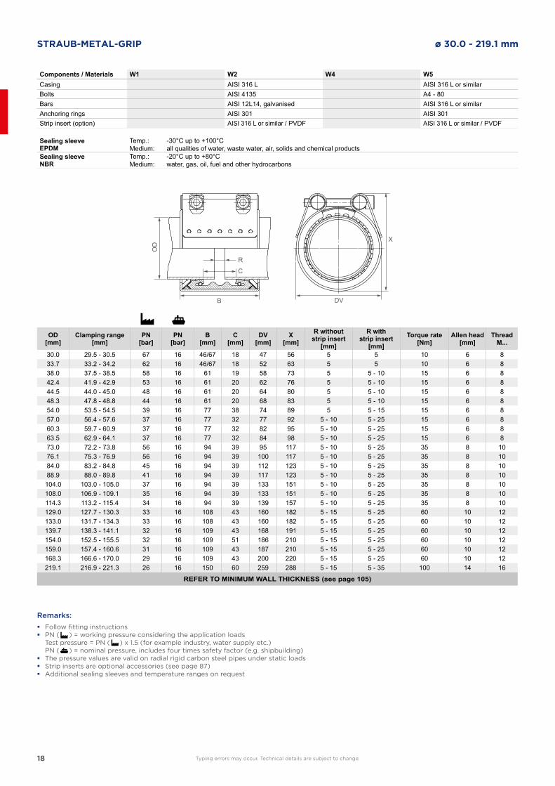
STRAUB-METAL-GRIP ø 30.0 - 219.1 mm
Components / Materials W1 W2 W4 W5Casing AISI 316 L AISI 316 L or similarBolts AISI 4135 A4 - 80Bars AISI 12L14, galvanised AISI 316 L or similarAnchoring rings AISI 301 AISI 301Strip insert (option) AISI 316 L or similar / PVDF AISI 316 L or similar / PVDF
Sealing sleeve EPDM
Temp.:Medium:
-30°C up to +100°Call qualities of water, waste water, air, solids and chemical products
Sealing sleeve NBR
Temp.:Medium:
-20°C up to +80°Cwater, gas, oil, fuel and other hydrocarbons
OD[mm]
Clamping range[mm]
PN[bar]
PN[bar]
B[mm]
C[mm]
DV[mm]
X[mm]
R withoutstrip insert
[mm]
R withstrip insert
[mm]Torque rate
[Nm]Allen head
[mm]Thread
M...
30.0 29.5 - 30.5 67 16 46/67 18 47 56 5 5 10 6 833.7 33.2 - 34.2 62 16 46/67 18 52 63 5 5 10 6 838.0 37.5 - 38.5 58 16 61 19 58 73 5 5 - 10 15 6 842.4 41.9 - 42.9 53 16 61 20 62 76 5 5 - 10 15 6 844.5 44.0 - 45.0 48 16 61 20 64 80 5 5 - 10 15 6 848.3 47.8 - 48.8 44 16 61 20 68 83 5 5 - 10 15 6 854.0 53.5 - 54.5 39 16 77 38 74 89 5 5 - 15 15 6 857.0 56.4 - 57.6 37 16 77 32 77 92 5 - 10 5 - 25 15 6 860.3 59.7 - 60.9 37 16 77 32 82 95 5 - 10 5 - 25 15 6 863.5 62.9 - 64.1 37 16 77 32 84 98 5 - 10 5 - 25 15 6 873.0 72.2 - 73.8 56 16 94 39 95 117 5 - 10 5 - 25 35 8 1076.1 75.3 - 76.9 56 16 94 39 100 117 5 - 10 5 - 25 35 8 1084.0 83.2 - 84.8 45 16 94 39 112 123 5 - 10 5 - 25 35 8 1088.9 88.0 - 89.8 41 16 94 39 117 123 5 - 10 5 - 25 35 8 10104.0 103.0 - 105.0 37 16 94 39 133 151 5 - 10 5 - 25 35 8 10108.0 106.9 - 109.1 35 16 94 39 133 151 5 - 10 5 - 25 35 8 10114.3 113.2 - 115.4 34 16 94 39 139 157 5 - 10 5 - 25 35 8 10129.0 127.7 - 130.3 33 16 108 43 160 182 5 - 15 5 - 25 60 10 12133.0 131.7 - 134.3 33 16 108 43 160 182 5 - 15 5 - 25 60 10 12139.7 138.3 - 141.1 32 16 109 43 168 191 5 - 15 5 - 25 60 10 12154.0 152.5 - 155.5 32 16 109 51 186 210 5 - 15 5 - 25 60 10 12159.0 157.4 - 160.6 31 16 109 43 187 210 5 - 15 5 - 25 60 10 12168.3 166.6 - 170.0 29 16 109 43 200 220 5 - 15 5 - 25 60 10 12219.1 216.9 - 221.3 26 16 150 60 259 288 5 - 15 5 - 35 100 14 16
REFER TO MINIMUM WALL THICKNESS (see page 105)
DVB
OD
R
C
X
Remarks:
� Follow fitting instructions � PN ( ) = working pressure considering the application loads
Test pressure = PN ( ) x 1.5 (for example industry, water supply etc.) PN ( ) = nominal pressure, includes four times safety factor (e.g. shipbuilding) � The pressure values are valid on radial rigid carbon steel pipes under static loads � Strip inserts are optional accessories (see page 87) � Additional sealing sleeves and temperature ranges on request
Typing errors may occur. Technical details are subject to change.
19
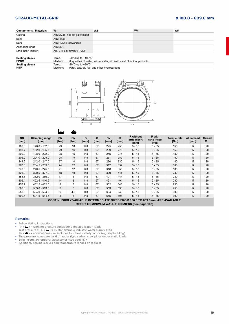
STRAUB-METAL-GRIP ø 180.0 - 609.6 mm
Sealing sleeve EPDM
Temp.:Medium:
-20°C up to +100°Call qualities of water, waste water, air, solids and chemical products
Sealing sleeve NBR
Temp.:Medium:
-20°C up to +80°Cwater, gas, oil, fuel and other hydrocarbons
Components / Materials W1 W2 W4 W5Casing AISI A738, hot-dip galvanisedBolts AISI 4135Bars AISI 12L14, galvanisedAnchoring rings AISI 301Strip insert (option) AISI 316 L or similar / PVDF
OD[mm]
Clamping range[mm]
PN[bar]
PN[bar]
B[mm]
C[mm]
DV[mm]
X[mm]
R withoutstrip insert
[mm]
R withstrip insert
[mm]Torque rate
[Nm]Allen head
[mm]Thread
M...
180.0 178.0 - 182.0 29 16 148 67 225 256 5 - 15 5 - 35 150 17 20193.7 192.0 - 195.5 29 16 148 67 239 270 5 - 15 5 - 35 150 17 20200.0 198.0 - 202.0 28 15 148 67 245 276 5 - 15 5 - 35 180 17 20206.0 204.0 - 208.0 28 15 148 67 251 282 5 - 15 5 - 35 180 17 20244.5 242.0 - 247.0 27 14 148 67 290 330 5 - 15 5 - 35 180 17 20267.0 264.5 - 269.5 24 12 148 67 312 352 5 - 15 5 - 35 180 17 20273.0 270.5 - 275.5 21 12 148 67 318 359 5 - 15 5 - 35 180 17 20323.9 320.5 - 327.0 18 10 148 67 369 411 5 - 15 5 - 35 230 17 20355.6 352.0 - 359.0 17 8 148 67 401 444 5 - 15 5 - 35 230 17 20406.4 402.5 - 410.5 14 8 148 67 451 494 5 - 15 5 - 35 230 17 20457.2 452.5 - 462.0 8 6 148 67 502 546 5 - 15 5 - 35 250 17 20508.0 503.0 - 513.0 6 5 148 67 553 598 5 - 15 5 - 35 250 17 20558.8 554.0 - 564.0 6 4.5 148 67 604 649 5 - 15 5 - 35 300 17 20609.6 604.5 - 614.5 5 4 148 67 655 701 5 - 15 5 - 35 300 17 20
CONTINUOUSLY VARIABLE INTERMEDIATE SIZES FROM 180.0 TO 609.6 mm ARE AVAILABLEREFER TO MINIMUM WALL THICKNESS (see page 105)
Remarks:
� Follow fitting instructions � PN ( ) = working pressure considering the application loads
Test pressure = PN ( ) x 1.5 (for example industry, water supply etc.) PN ( ) = nominal pressure, includes four times safety factor (e.g. shipbuilding) � The pressure values are valid on radial rigid carbon steel pipes under static loads � Strip inserts are optional accessories (see page 87) � Additional sealing sleeves and temperature ranges on request
DVB
OD
R
C
X
Typing errors may occur. Technical details are subject to change.
20
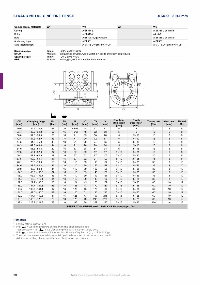
STRAUB-METAL-GRIP-FIRE-FENCE ø 30.0 - 219.1 mm
DVB
OD
RC
X
Components / Materials W1 W2 W4 W5Casing AISI 316 L AISI 316 L or similarBolts AISI 4135 A4 - 80Bars AISI 12L14, galvanised AISI 316 L or similarAnchoring rings AISI 301 AISI 301Strip insert (option) AISI 316 L or similar / PVDF AISI 316 L or similar / PVDF
Sealing sleeve EPDM
Temp.:Medium:
-30°C up to +100°Call qualities of water, waste water, air, solids and chemical products
Sealing sleeve NBR
Temp.:Medium:
-20°C up to +80°Cwater, gas, oil, fuel and other hydrocarbons
OD[mm]
Clamping range[mm]
PN[bar]
PN[bar]
B[mm]
C[mm]
DV[mm]
X[mm]
R withoutstrip insert
[mm]
R withstrip insert
[mm]Torque rate
[Nm]Allen head
[mm]Thread
M...
30.0 29.5 - 30.5 67 16 46/67 18 57 61 5 5 10 6 833.7 33.2 - 34.2 62 16 46/67 18 62 68 5 5 10 6 838.0 37.5 - 38.5 58 16 71 19 68 78 5 5 - 10 15 6 842.4 41.9 - 42.9 53 16 71 20 72 81 5 5 - 10 15 6 844.5 44.0 - 45.0 48 16 71 20 74 85 5 5 - 10 15 6 848.3 47.8 - 48.8 44 16 71 20 78 88 5 5 - 10 15 6 854.0 53.5 - 54.5 39 16 87 38 84 94 5 5 - 15 15 6 857.0 56.4 - 57.6 37 16 87 32 87 97 5 - 10 5 - 25 15 6 860.3 59.7 - 60.9 37 16 87 32 87 100 5 - 10 5 - 25 15 6 863.5 62.9 - 64.1 37 16 87 32 94 103 5 - 10 5 - 25 15 6 876.1 75.3 - 76.9 56 16 110 39 110 122 5 - 10 5 - 25 35 8 1084.0 83.2 - 84.8 45 16 110 39 122 128 5 - 10 5 - 25 35 8 1088.9 88.0 - 89.8 41 16 110 39 127 128 5 - 10 5 - 25 35 8 10104.0 103.0 - 105.0 37 16 110 39 143 156 5 - 10 5 - 25 35 8 10108.0 106.9 - 109.1 35 16 110 39 143 156 5 - 10 5 - 25 35 8 10114.3 113.2 - 115.4 34 16 110 39 149 162 5 - 10 5 - 25 35 8 10129.0 127.7 - 130.3 33 16 124 43 170 187 5 - 15 5 - 25 60 10 12133.0 131.7 - 134.3 33 16 125 43 170 187 5 - 15 5 - 25 60 10 12139.7 138.3 - 141.1 32 16 125 43 178 196 5 - 15 5 - 25 60 10 12154.0 152.5 - 155.5 32 16 125 51 196 215 5 - 15 5 - 25 60 10 12159.0 157.4 - 160.6 31 16 125 43 197 215 5 - 15 5 - 25 60 10 12168.3 166.6 - 170.0 29 16 125 43 210 225 5 - 15 5 - 25 60 10 12219.1 216.9 - 221.3 26 16 166 60 269 293 5 - 15 5 - 35 100 14 16
REFER TO MINIMUM WALL THICKNESS (see page 105)
Remarks:
� Follow fitting instructions � PN ( ) = working pressure considering the application loads
Test pressure = PN ( ) x 1.5 (for example industry, water supply etc.) PN ( ) = nominal pressure, includes four times safety factor (e.g. shipbuilding) � The pressure values are valid on radial rigid carbon steel pipes under static loads � Additional sealing sleeves and temperature ranges on request
Typing errors may occur. Technical details are subject to change.
21
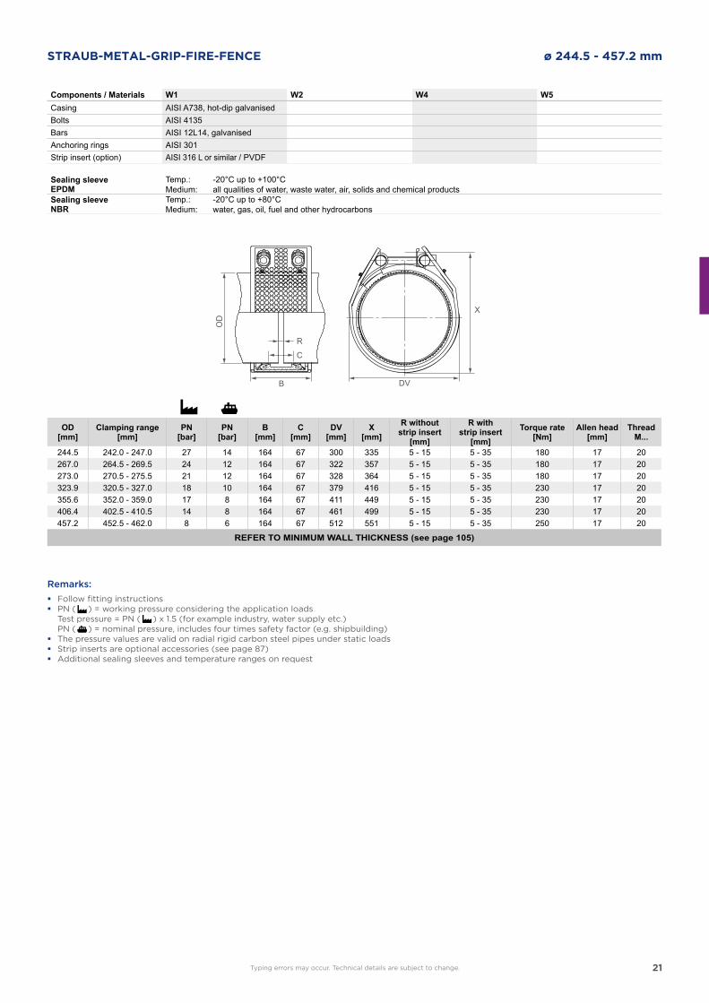
STRAUB-METAL-GRIP-FIRE-FENCE ø 244.5 - 457.2 mm
DVB
OD
R
C
X
Components / Materials W1 W2 W4 W5Casing AISI A738, hot-dip galvanisedBolts AISI 4135Bars AISI 12L14, galvanisedAnchoring rings AISI 301Strip insert (option) AISI 316 L or similar / PVDF
Sealing sleeve EPDM
Temp.:Medium:
-20°C up to +100°Call qualities of water, waste water, air, solids and chemical products
Sealing sleeve NBR
Temp.:Medium:
-20°C up to +80°Cwater, gas, oil, fuel and other hydrocarbons
OD[mm]
Clamping range[mm]
PN[bar]
PN[bar]
B[mm]
C[mm]
DV[mm]
X[mm]
R withoutstrip insert
[mm]
R withstrip insert
[mm]Torque rate
[Nm]Allen head
[mm]Thread
M...
244.5 242.0 - 247.0 27 14 164 67 300 335 5 - 15 5 - 35 180 17 20267.0 264.5 - 269.5 24 12 164 67 322 357 5 - 15 5 - 35 180 17 20273.0 270.5 - 275.5 21 12 164 67 328 364 5 - 15 5 - 35 180 17 20323.9 320.5 - 327.0 18 10 164 67 379 416 5 - 15 5 - 35 230 17 20355.6 352.0 - 359.0 17 8 164 67 411 449 5 - 15 5 - 35 230 17 20406.4 402.5 - 410.5 14 8 164 67 461 499 5 - 15 5 - 35 230 17 20457.2 452.5 - 462.0 8 6 164 67 512 551 5 - 15 5 - 35 250 17 20
REFER TO MINIMUM WALL THICKNESS (see page 105)
Remarks:
� Follow fitting instructions � PN ( ) = working pressure considering the application loads
Test pressure = PN ( ) x 1.5 (for example industry, water supply etc.) PN ( ) = nominal pressure, includes four times safety factor (e.g. shipbuilding) � The pressure values are valid on radial rigid carbon steel pipes under static loads � Strip inserts are optional accessories (see page 87) � Additional sealing sleeves and temperature ranges on request
Typing errors may occur. Technical details are subject to change.
22
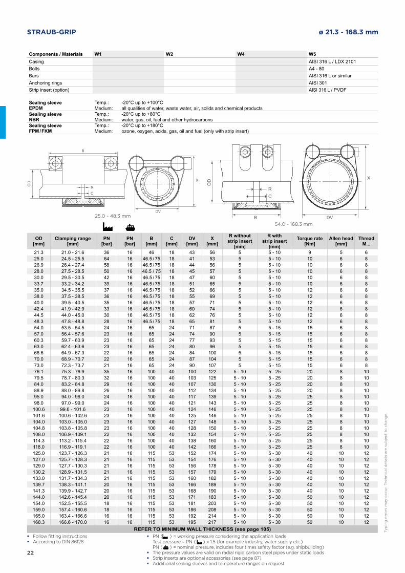
STRAUB-GRIP ø 21.3 - 168.3 mm
25.0 - 48.3 mm
54.0 - 168.3 mm
Sealing sleeve EPDM
Temp.:Medium:
-20°C up to +100°Call qualities of water, waste water, air, solids and chemical products
Sealing sleeve NBR
Temp.:Medium:
-20°C up to +80°Cwater, gas, oil, fuel and other hydrocarbons
Sealing sleeveFPM / FKM
Temp.:Medium:
-20°C up to +180°Cozone, oxygen, acids, gas, oil and fuel (only with strip insert)
Components / Materials W1 W2 W4 W5Casing AISI 316 L / LDX 2101Bolts A4 - 80Bars AISI 316 L or similarAnchoring rings AISI 301Strip insert (option) AISI 316 L / PVDF
OD[mm]
Clamping range[mm]
PN[bar]
PN[bar]
B[mm]
C[mm]
DV[mm]
X[mm]
R withoutstrip insert
[mm]
R withstrip insert
[mm]Torque rate
[Nm]Allen head
[mm]Thread
M...
21.3 21.0 - 21.6 36 16 46 18 43 56 5 5 - 10 9 5 625.0 24.5 - 25.5 64 16 46.5 / 75 18 41 53 5 5 - 10 10 6 826.9 26.4 - 27.4 58 16 46.5 / 75 18 44 56 5 5 - 10 10 6 828.0 27.5 - 28.5 50 16 46.5 / 75 18 45 57 5 5 - 10 10 6 830.0 29.5 - 30.5 42 16 46.5 / 75 18 47 60 5 5 - 10 10 6 833.7 33.2 - 34.2 39 16 46.5 / 75 18 51 65 5 5 - 10 10 6 835.0 34.5 - 35.5 37 16 46.5 / 75 18 52 66 5 5 - 10 12 6 838.0 37.5 - 38.5 36 16 46.5 / 75 18 55 69 5 5 - 10 12 6 840.0 39.5 - 40.5 35 16 46.5 / 75 18 57 71 5 5 - 10 12 6 842.4 41.9 - 42.9 33 16 46.5 / 75 18 60 74 5 5 - 10 12 6 844.5 44.0 - 45.0 30 16 46.5 / 75 18 62 76 5 5 - 10 12 6 848.3 47.8 - 48.8 28 16 46.5 / 75 18 65 81 5 5 - 10 12 6 854.0 53.5 - 54.5 24 16 65 24 71 87 5 5 - 15 15 6 857.0 56.4 - 57.6 23 16 65 24 74 90 5 5 - 15 15 6 860.3 59.7 - 60.9 23 16 65 24 77 93 5 5 - 15 15 6 863.0 62.4 - 63.6 23 16 65 24 80 96 5 5 - 15 15 6 866.6 64.9 - 67.3 22 16 65 24 84 100 5 5 - 15 15 6 870.0 68.9 - 70.7 22 16 65 24 87 104 5 5 - 15 15 6 873.0 72.3 - 73.7 21 16 65 24 90 107 5 5 - 15 15 6 876.1 75.3 - 76.9 35 16 100 40 100 122 5 - 10 5 - 25 20 8 1079.5 78.7 - 80.3 32 16 100 40 103 125 5 - 10 5 - 25 20 8 1084.0 83.2 - 84.8 29 16 100 40 107 130 5 - 10 5 - 25 20 8 1088.9 88.0 - 89.8 26 16 100 40 112 134 5 - 10 5 - 25 20 8 1095.0 94.0 - 96.0 24 16 100 40 117 139 5 - 10 5 - 25 25 8 1098.0 97.0 - 99.0 24 16 100 40 121 143 5 - 10 5 - 25 25 8 10100.6 99.6 - 101.6 23 16 100 40 124 146 5 - 10 5 - 25 25 8 10101.6 100.6 - 102.6 23 16 100 40 125 146 5 - 10 5 - 25 25 8 10104.0 103.0 - 105.0 23 16 100 40 127 148 5 - 10 5 - 25 25 8 10104.8 103.8 - 105.8 23 16 100 40 128 150 5 - 10 5 - 25 25 8 10108.0 106.9 - 109.1 22 16 100 40 132 154 5 - 10 5 - 25 25 8 10114.3 113.2 - 115.4 22 16 100 40 138 160 5 - 10 5 - 25 25 8 10118.0 116.9 - 119.1 22 16 100 40 142 166 5 - 10 5 - 25 25 8 10125.0 123.7 - 126.3 21 16 115 53 152 174 5 - 10 5 - 30 40 10 12127.0 125.7 - 128.3 21 16 115 53 154 176 5 - 10 5 - 30 40 10 12129.0 127.7 - 130.3 21 16 115 53 156 178 5 - 10 5 - 30 40 10 12130.2 128.9 - 131.5 21 16 115 53 157 179 5 - 10 5 - 30 40 10 12133.0 131.7 - 134.3 21 16 115 53 160 182 5 - 10 5 - 30 40 10 12139.7 138.3 - 141.1 20 16 115 53 166 189 5 - 10 5 - 30 40 10 12141.3 139.9 - 142.7 20 16 115 53 168 190 5 - 10 5 - 30 40 10 12144.0 142.6 - 145.4 20 16 115 53 171 183 5 - 10 5 - 30 50 10 12154.0 152.5 - 155.5 18 16 115 53 181 203 5 - 10 5 - 30 50 10 12159.0 157.4 - 160.6 18 16 115 53 186 208 5 - 10 5 - 30 50 10 12165.0 163.4 - 166.6 16 16 115 53 192 214 5 - 10 5 - 30 50 10 12168.3 166.6 - 170.0 16 16 115 53 195 217 5 - 10 5 - 30 50 10 12
REFER TO MINIMUM WALL THICKNESS (see page 105)
DV
B
OD
RC
X
DVB
OD
RC
X
� Follow fitting instructions � According to DIN 86128
� PN ( ) = working pressure considering the application loads Test pressure = PN ( ) x 1.5 (for example industry, water supply etc.) PN ( ) = nominal pressure, includes four times safety factor (e.g. shipbuilding) � The pressure values are valid on radial rigid carbon steel pipes under static loads � Strip inserts are optional accessories (see page 87) � Additional sealing sleeves and temperature ranges on request
Typ
ing
err
ors
may o
ccu
r. T
ech
nic
al d
eta
ils a
re s
ub
ject
to c
han
ge.
23
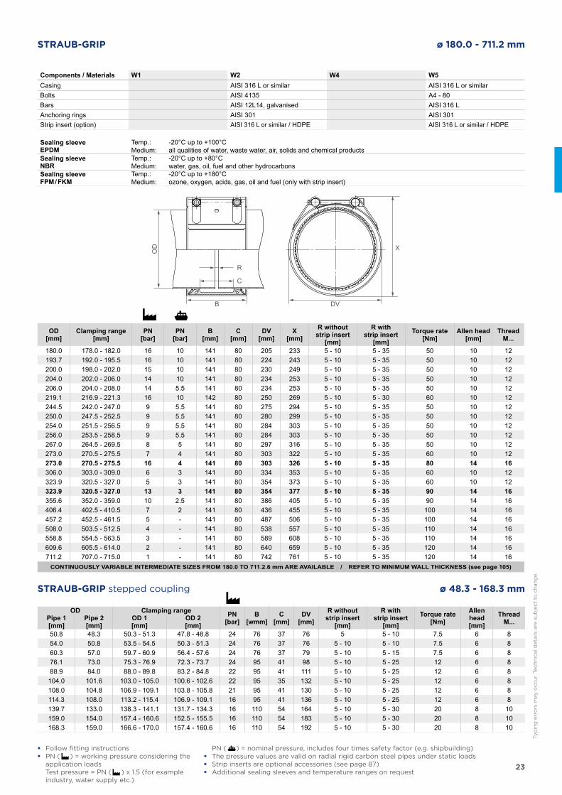
STRAUB-GRIP ø 180.0 - 711.2 mm
DVB
OD
R
C
X
Components / Materials W1 W2 W4 W5Casing AISI 316 L or similar AISI 316 L or similarBolts AISI 4135 A4 - 80Bars AISI 12L14, galvanised AISI 316 LAnchoring rings AISI 301 AISI 301Strip insert (option) AISI 316 L or similar / HDPE AISI 316 L or similar / HDPE
Sealing sleeve EPDM
Temp.:Medium:
-20°C up to +100°Call qualities of water, waste water, air, solids and chemical products
Sealing sleeve NBR
Temp.:Medium:
-20°C up to +80°Cwater, gas, oil, fuel and other hydrocarbons
Sealing sleeve FPM / FKM
Temp.:Medium:
-20°C up to +180°Cozone, oxygen, acids, gas, oil and fuel (only with strip insert)
OD[mm]
Clamping range[mm]
PN[bar]
PN[bar]
B[mm]
C[mm]
DV[mm]
X[mm]
R withoutstrip insert
[mm]
R withstrip insert
[mm]Torque rate
[Nm]Allen head
[mm]Thread
M...
180.0 178.0 - 182.0 16 10 141 80 205 233 5 - 10 5 - 35 50 10 12193.7 192.0 - 195.5 16 10 141 80 224 243 5 - 10 5 - 35 50 10 12200.0 198.0 - 202.0 15 10 141 80 230 249 5 - 10 5 - 35 50 10 12204.0 202.0 - 206.0 14 10 141 80 234 253 5 - 10 5 - 35 50 10 12206.0 204.0 - 208.0 14 5.5 141 80 234 253 5 - 10 5 - 35 50 10 12219.1 216.9 - 221.3 16 10 142 80 250 269 5 - 10 5 - 30 60 10 12244.5 242.0 - 247.0 9 5.5 141 80 275 294 5 - 10 5 - 35 50 10 12250.0 247.5 - 252.5 9 5.5 141 80 280 299 5 - 10 5 - 35 50 10 12254.0 251.5 - 256.5 9 5.5 141 80 284 303 5 - 10 5 - 35 50 10 12256.0 253.5 - 258.5 9 5.5 141 80 284 303 5 - 10 5 - 35 50 10 12267.0 264.5 - 269.5 8 5 141 80 297 316 5 - 10 5 - 35 50 10 12273.0 270.5 - 275.5 7 4 141 80 303 322 5 - 10 5 - 35 60 10 12273.0 270.5 - 275.5 16 4 141 80 303 326 5 - 10 5 - 35 80 14 16306.0 303.0 - 309.0 6 3 141 80 334 353 5 - 10 5 - 35 60 10 12323.9 320.5 - 327.0 5 3 141 80 354 373 5 - 10 5 - 35 60 10 12323.9 320.5 - 327.0 13 3 141 80 354 377 5 - 10 5 - 35 90 14 16355.6 352.0 - 359.0 10 2.5 141 80 386 405 5 - 10 5 - 35 90 14 16406.4 402.5 - 410.5 7 2 141 80 436 455 5 - 10 5 - 35 100 14 16457.2 452.5 - 461.5 5 - 141 80 487 506 5 - 10 5 - 35 100 14 16508.0 503.5 - 512.5 4 - 141 80 538 557 5 - 10 5 - 35 110 14 16558.8 554.5 - 563.5 3 - 141 80 589 608 5 - 10 5 - 35 110 14 16609.6 605.5 - 614.0 2 - 141 80 640 659 5 - 10 5 - 35 120 14 16711.2 707.0 - 715.0 1 - 141 80 742 761 5 - 10 5 - 35 120 14 16
CONTINUOUSLY VARIABLE INTERMEDIATE SIZES FROM 180.0 TO 711.2.6 mm ARE AVAILABLE / REFER TO MINIMUM WALL THICKNESS (see page 105)
� Follow fitting instructions � PN ( ) = working pressure considering the
application loads Test pressure = PN ( ) x 1.5 (for example
industry, water supply etc.)
OD Clamping range PN[bar]
B[wmm]
C[mm]
DV[mm]
R withoutstrip insert
[mm]
R withstrip insert
[mm]Torque rate
[Nm]Allen head[mm]
ThreadM...Pipe 1
[mm]Pipe 2[mm]
OD 1[mm]
OD 2[mm]
50.8 48.3 50.3 - 51.3 47.8 - 48.8 24 76 37 76 5 5 - 10 7.5 6 854.0 50.8 53.5 - 54.5 50.3 - 51.3 24 76 37 76 5 - 10 5 - 10 7.5 6 860.3 57.0 59.7 - 60.9 56.4 - 57.6 24 76 37 79 5 - 10 5 - 15 7.5 6 876.1 73.0 75.3 - 76.9 72.3 - 73.7 24 95 41 98 5 - 10 5 - 25 12 6 888.9 84.0 88.0 - 89.8 83.2 - 84.8 22 95 41 111 5 - 10 5 - 25 12 6 8104.0 101.6 103.0 - 105.0 100.6 - 102.6 22 95 35 132 5 - 10 5 - 25 12 6 8108.0 104.8 106.9 - 109.1 103.8 - 105.8 21 95 41 130 5 - 10 5 - 25 12 6 8114.3 108.0 113.2 - 115.4 106.9 - 109.1 16 95 41 136 5 - 10 5 - 25 12 6 8139.7 133.0 138.3 - 141.1 131.7 - 134.3 16 110 54 164 5 - 10 5 - 30 20 8 10159.0 154.0 157.4 - 160.6 152.5 - 155.5 16 110 54 183 5 - 10 5 - 30 20 8 10168.3 159.0 166.6 - 170.0 157.4 - 160.6 16 110 54 192 5 - 10 5 - 30 20 8 10
STRAUB-GRIP stepped coupling ø 48.3 - 168.3 mm
Typ
ing
err
ors
may o
ccu
r. T
ech
nic
al d
eta
ils a
re s
ub
ject
to c
han
ge.
PN ( ) = nominal pressure, includes four times safety factor (e.g. shipbuilding) � The pressure values are valid on radial rigid carbon steel pipes under static loads � Strip inserts are optional accessories (see page 87) � Additional sealing sleeves and temperature ranges on request
24
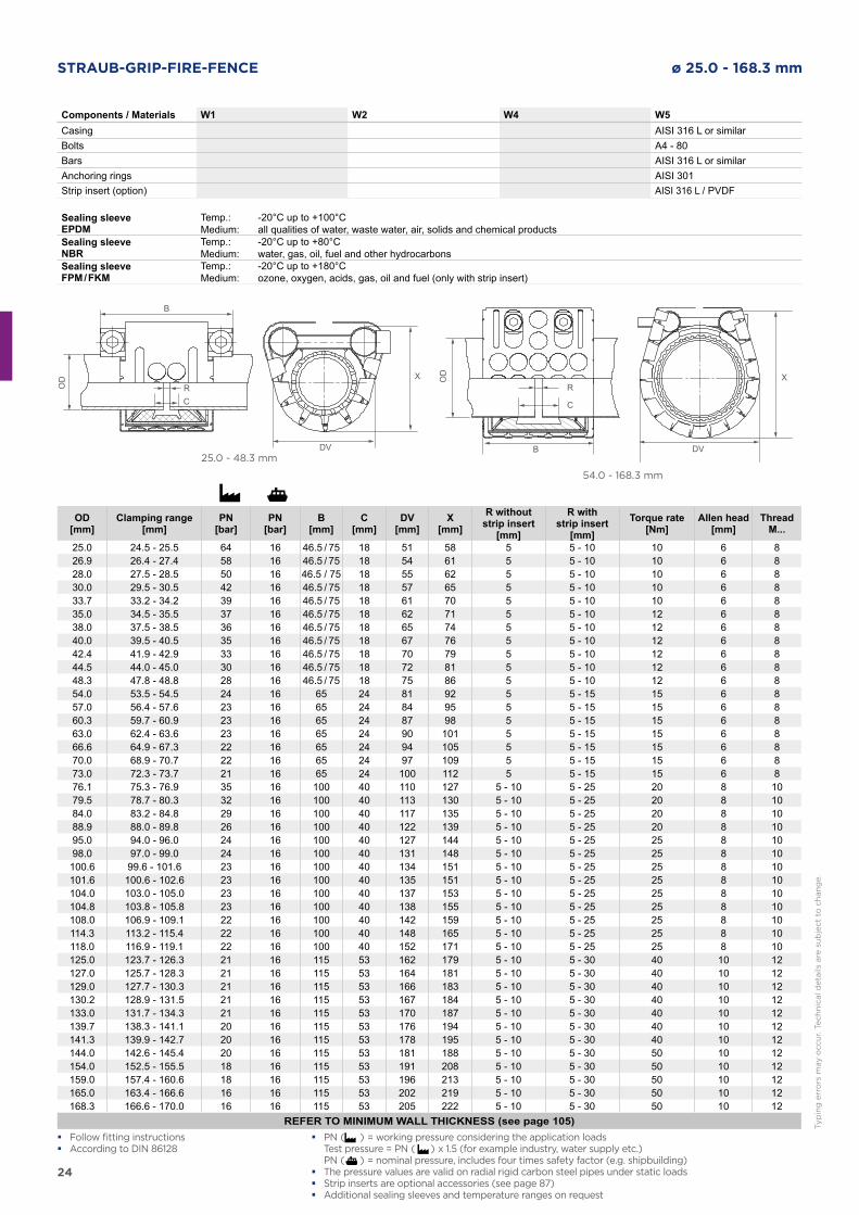
STRAUB-GRIP-FIRE-FENCE ø 25.0 - 168.3 mm
25.0 - 48.3 mm
54.0 - 168.3 mm
DV
B
OD
RC
X
Components / Materials W1 W2 W4 W5Casing AISI 316 L or similarBolts A4 - 80Bars AISI 316 L or similarAnchoring rings AISI 301Strip insert (option) AISI 316 L / PVDF
Sealing sleeve EPDM
Temp.:Medium:
-20°C up to +100°Call qualities of water, waste water, air, solids and chemical products
Sealing sleeve NBR
Temp.:Medium:
-20°C up to +80°Cwater, gas, oil, fuel and other hydrocarbons
Sealing sleeve FPM / FKM
Temp.:Medium:
-20°C up to +180°Cozone, oxygen, acids, gas, oil and fuel (only with strip insert)
DVBO
D
R
C
X
OD[mm]
Clamping range[mm]
PN[bar]
PN[bar]
B[mm]
C[mm]
DV[mm]
X[mm]
R withoutstrip insert
[mm]
R withstrip insert
[mm]Torque rate
[Nm]Allen head
[mm]Thread
M...
25.0 24.5 - 25.5 64 16 46.5 / 75 18 51 58 5 5 - 10 10 6 826.9 26.4 - 27.4 58 16 46.5 / 75 18 54 61 5 5 - 10 10 6 828.0 27.5 - 28.5 50 16 46.5 / 75 18 55 62 5 5 - 10 10 6 830.0 29.5 - 30.5 42 16 46.5 / 75 18 57 65 5 5 - 10 10 6 833.7 33.2 - 34.2 39 16 46.5 / 75 18 61 70 5 5 - 10 10 6 835.0 34.5 - 35.5 37 16 46.5 / 75 18 62 71 5 5 - 10 12 6 838.0 37.5 - 38.5 36 16 46.5 / 75 18 65 74 5 5 - 10 12 6 840.0 39.5 - 40.5 35 16 46.5 / 75 18 67 76 5 5 - 10 12 6 842.4 41.9 - 42.9 33 16 46.5 / 75 18 70 79 5 5 - 10 12 6 844.5 44.0 - 45.0 30 16 46.5 / 75 18 72 81 5 5 - 10 12 6 848.3 47.8 - 48.8 28 16 46.5 / 75 18 75 86 5 5 - 10 12 6 854.0 53.5 - 54.5 24 16 65 24 81 92 5 5 - 15 15 6 857.0 56.4 - 57.6 23 16 65 24 84 95 5 5 - 15 15 6 860.3 59.7 - 60.9 23 16 65 24 87 98 5 5 - 15 15 6 863.0 62.4 - 63.6 23 16 65 24 90 101 5 5 - 15 15 6 866.6 64.9 - 67.3 22 16 65 24 94 105 5 5 - 15 15 6 870.0 68.9 - 70.7 22 16 65 24 97 109 5 5 - 15 15 6 873.0 72.3 - 73.7 21 16 65 24 100 112 5 5 - 15 15 6 876.1 75.3 - 76.9 35 16 100 40 110 127 5 - 10 5 - 25 20 8 1079.5 78.7 - 80.3 32 16 100 40 113 130 5 - 10 5 - 25 20 8 1084.0 83.2 - 84.8 29 16 100 40 117 135 5 - 10 5 - 25 20 8 1088.9 88.0 - 89.8 26 16 100 40 122 139 5 - 10 5 - 25 20 8 1095.0 94.0 - 96.0 24 16 100 40 127 144 5 - 10 5 - 25 25 8 1098.0 97.0 - 99.0 24 16 100 40 131 148 5 - 10 5 - 25 25 8 10100.6 99.6 - 101.6 23 16 100 40 134 151 5 - 10 5 - 25 25 8 10101.6 100.6 - 102.6 23 16 100 40 135 151 5 - 10 5 - 25 25 8 10104.0 103.0 - 105.0 23 16 100 40 137 153 5 - 10 5 - 25 25 8 10104.8 103.8 - 105.8 23 16 100 40 138 155 5 - 10 5 - 25 25 8 10108.0 106.9 - 109.1 22 16 100 40 142 159 5 - 10 5 - 25 25 8 10114.3 113.2 - 115.4 22 16 100 40 148 165 5 - 10 5 - 25 25 8 10118.0 116.9 - 119.1 22 16 100 40 152 171 5 - 10 5 - 25 25 8 10125.0 123.7 - 126.3 21 16 115 53 162 179 5 - 10 5 - 30 40 10 12127.0 125.7 - 128.3 21 16 115 53 164 181 5 - 10 5 - 30 40 10 12129.0 127.7 - 130.3 21 16 115 53 166 183 5 - 10 5 - 30 40 10 12130.2 128.9 - 131.5 21 16 115 53 167 184 5 - 10 5 - 30 40 10 12133.0 131.7 - 134.3 21 16 115 53 170 187 5 - 10 5 - 30 40 10 12139.7 138.3 - 141.1 20 16 115 53 176 194 5 - 10 5 - 30 40 10 12141.3 139.9 - 142.7 20 16 115 53 178 195 5 - 10 5 - 30 40 10 12144.0 142.6 - 145.4 20 16 115 53 181 188 5 - 10 5 - 30 50 10 12154.0 152.5 - 155.5 18 16 115 53 191 208 5 - 10 5 - 30 50 10 12159.0 157.4 - 160.6 18 16 115 53 196 213 5 - 10 5 - 30 50 10 12165.0 163.4 - 166.6 16 16 115 53 202 219 5 - 10 5 - 30 50 10 12168.3 166.6 - 170.0 16 16 115 53 205 222 5 - 10 5 - 30 50 10 12
REFER TO MINIMUM WALL THICKNESS (see page 105) � Follow fitting instructions � According to DIN 86128
� PN ( ) = working pressure considering the application loads Test pressure = PN ( ) x 1.5 (for example industry, water supply etc.) PN ( ) = nominal pressure, includes four times safety factor (e.g. shipbuilding) � The pressure values are valid on radial rigid carbon steel pipes under static loads � Strip inserts are optional accessories (see page 87) � Additional sealing sleeves and temperature ranges on request
Typ
ing
err
ors
may o
ccu
r. T
ech
nic
al d
eta
ils a
re s
ub
ject
to c
han
ge.
25
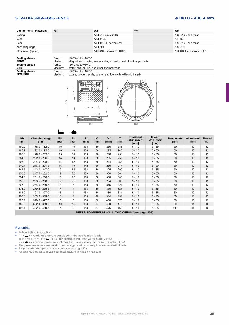
STRAUB-GRIP-FIRE-FENCE ø 180.0 - 406.4 mm
DVB
OD
R
C
X
Components / Materials W1 W2 W4 W5Casing AISI 316 L or similar AISI 316 L or similarBolts AISI 4135 A4 - 80Bars AISI 12L14, galvanised AISI 316 L or similarAnchoring rings AISI 301 AISI 301Strip insert (option) AISI 316 L or similar / HDPE AISI 316 L or similar / HDPE
Sealing sleeve EPDM
Temp.:Medium:
-20°C up to +100°Call qualities of water, waste water, air, solids and chemical products
Sealing sleeve NBR
Temp.:Medium:
-20°C up to +80°Cwater, gas, oil, fuel and other hydrocarbons
Sealing sleeve FPM / FKM
Temp.:Medium:
-20°C up to +180°Cozone, oxygen, acids, gas, oil and fuel (only with strip insert)
OD[mm]
Clamping range[mm]
PN[bar]
PN[bar]
B[mm]
C[mm]
DV[mm]
X[mm]
R withoutstrip insert
[mm]
R withstrip insert
[mm]Torque rate
[Nm]Allen head
[mm]Thread
M...
180.0 178.0 - 182.0 16 10 158 80 260 238 5 - 10 5 - 35 50 10 12193.7 192.0 - 195.5 16 10 158 80 275 248 5 - 10 5 - 35 50 10 12200.0 198.0 - 202.0 15 10 158 80 280 254 5 - 10 5 - 35 50 10 12204.0 202.0 - 206.0 14 10 158 80 285 258 5 - 10 5 - 35 50 10 12206.0 204.0 - 208.0 14 5.5 158 80 234 258 5 - 10 5 - 35 50 10 12219.1 216.9 - 221.3 16 10 142 80 250 274 5 - 10 5 - 30 60 10 12244.5 242.0 - 247.0 9 5.5 158 80 325 299 5 - 10 5 - 35 50 10 12250.0 247.5 - 252.5 9 5.5 158 80 330 304 5 - 10 5 - 35 50 10 12254.0 251.5 - 256.5 9 5.5 158 80 330 308 5 - 10 5 - 35 50 10 12256.0 253.5 - 258.5 9 5.5 158 80 284 308 5 - 10 5 - 35 50 10 12267.0 264.5 - 269.5 8 5 158 80 345 321 5 - 10 5 - 35 50 10 12273.0 270.5 - 275.5 7 4 158 80 350 327 5 - 10 5 - 35 60 10 12304.0 301.0 - 307.0 6 4 158 80 380 331 5 - 10 5 - 35 60 10 12306.0 303.0 - 309.0 6 3 158 80 334 358 5 - 10 5 - 35 60 10 12323.9 320.5 - 327.0 5 3 158 80 400 378 5 - 10 5 - 35 60 10 12355.6 352.0 - 359.0 10 2.5 158 67 430 410 5 - 10 5 - 35 90 14 16406.4 402.5 - 410.5 7 2 158 67 475 460 5 - 10 5 - 35 100 14 16
REFER TO MINIMUM WALL THICKNESS (see page 105)
Remarks:
� Follow fitting instructions � PN ( ) = working pressure considering the application loads
Test pressure = PN ( ) x 1.5 (for example industry, water supply etc.) PN ( ) = nominal pressure, includes four times safety factor (e.g. shipbuilding) � The pressure values are valid on radial rigid carbon steel pipes under static loads � Strip inserts are optional accessories (see page 87) � Additional sealing sleeves and temperature ranges on request
Typing errors may occur. Technical details are subject to change.
26
6bar
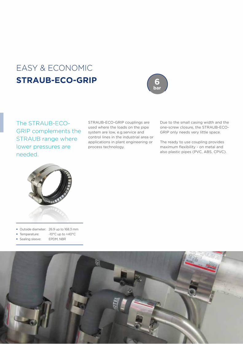
EASY & ECONOMIC
STRAUB-ECO-GRIP
STRAUB-ECO-GRIP couplings are used where the loads on the pipe system are low, e.g.service and control lines in the industrial area or applications in plant engineering or process technology.
The STRAUB-ECO-
GRIP complements the
STRAUB range where
lower pressures are
needed.
� Outside diameter: 26.9 up to 168.3 mm
� Temperature: -10°C up to +40°C
� Sealing sleeve: EPDM, NBR
Due to the small casing width and the one-screw closure, the STRAUB-ECO-GRIP only needs very little space.
The ready to use coupling provides maximum flexibility - on metal and also plastic pipes (PVC, ABS, CPVC).
27
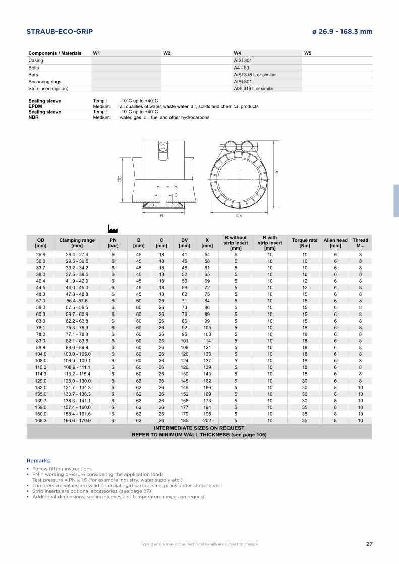
STRAUB-ECO-GRIP ø 26.9 - 168.3 mm
DVB
OD
R
C
X
Components / Materials W1 W2 W4 W5Casing AISI 301Bolts A4 - 80Bars AISI 316 L or similarAnchoring rings AISI 301Strip insert (option) AISI 316 L or similar
Sealing sleeve EPDM
Temp.:Medium:
-10°C up to +40°Call qualities of water, waste water, air, solids and chemical products
Sealing sleeve NBR
Temp.:Medium:
-10°C up to +40°Cwater, gas, oil, fuel and other hydrocarbons
OD[mm]
Clamping range[mm]
PN[bar]
B[mm]
C[mm]
DV[mm]
X[mm]
R withoutstrip insert
[mm]
R withstrip insert
[mm]Torque rate
[Nm]Allen head
[mm]Thread
M...
26.9 26.4 - 27.4 6 45 18 41 54 5 10 10 6 830.0 29.5 - 30.5 6 45 18 45 58 5 10 10 6 833.7 33.2 - 34.2 6 45 18 48 61 5 10 10 6 838.0 37.5 - 38.5 6 45 18 52 65 5 10 10 6 842.4 41.9 - 42.9 6 45 18 56 69 5 10 12 6 844.5 44.0 - 45.0 6 45 18 59 72 5 10 12 6 848.3 47.8 - 48.8 6 45 18 62 75 5 10 15 6 857.0 56.4 -57.6 6 60 26 71 84 5 10 15 6 858.0 57.5 - 58.5 6 60 26 73 86 5 10 15 6 860.3 59.7 - 60.9 6 60 26 76 89 5 10 15 6 863.0 62.2 - 63.8 6 60 26 86 99 5 10 15 6 876.1 75.3 - 76.9 6 60 26 92 105 5 10 18 6 878.0 77.1 - 78.8 6 60 26 95 108 5 10 18 6 883.0 82.1 - 83.8 6 60 26 101 114 5 10 18 6 888.9 88.0 - 89.8 6 60 26 108 121 5 10 18 6 8
104.0 103.0 - 105.0 6 60 26 120 133 5 10 18 6 8108.0 106.9 - 109.1 6 60 26 124 137 5 10 18 6 8110.0 108.9 - 111.1 6 60 26 126 139 5 10 18 6 8114.3 113.2 - 115.4 6 60 26 130 143 5 10 18 6 8129.0 128.0 - 130.0 6 62 26 145 162 5 10 30 6 8133.0 131.7 - 134.3 6 62 26 149 166 5 10 30 8 10135.0 133.7 - 136.3 6 62 26 152 169 5 10 30 8 10139.7 138.3 - 141.1 6 62 26 156 173 5 10 30 8 10159.0 157.4 - 160.6 6 62 26 177 194 5 10 35 8 10160.0 158.4 - 161.6 6 62 26 179 196 5 10 35 8 10168.3 166.6 - 170.0 6 62 26 185 202 5 10 35 8 10
INTERMEDIATE SIZES ON REQUESTREFER TO MINIMUM WALL THICKNESS (see page 105)
Remarks:
� Follow fitting instructions � PN = working pressure considering the application loads
Test pressure = PN x 1.5 (for example industry, water supply etc.) � The pressure values are valid on radial rigid carbon steel pipes under static loads � Strip inserts are optional accessories (see page 87) � Additional dimensions, sealing sleeves and temperature ranges on request
Typing errors may occur. Technical details are subject to change.
28
STRAUB-COMBI-GRIP STRAUB-PLAST-GRIP
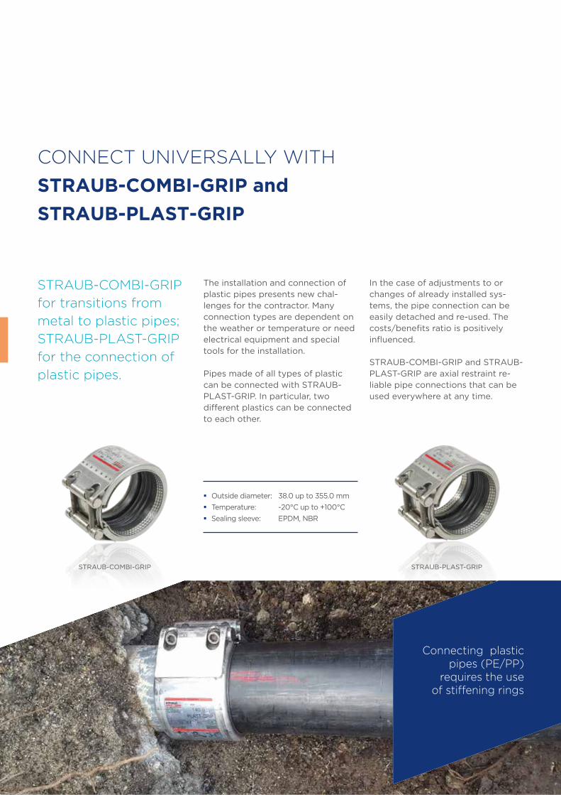
CONNECT UNIVERSALLY WITH
STRAUB-COMBI-GRIP and
STRAUB-PLAST-GRIP
The installation and connection of plastic pipes presents new chal-lenges for the contractor. Many connection types are dependent on the weather or temperature or need electrical equipment and special tools for the installation.
Pipes made of all types of plastic can be connected with STRAUB-PLAST-GRIP. In particular, two different plastics can be connected to each other.
STRAUB-COMBI-GRIP
for transitions from
metal to plastic pipes;
STRAUB-PLAST-GRIP
for the connection of
plastic pipes.
In the case of adjustments to or changes of already installed sys-tems, the pipe connection can be easily detached and re-used. The costs/benefits ratio is positively influenced.
STRAUB-COMBI-GRIP and STRAUB-PLAST-GRIP are axial restraint re-liable pipe connections that can be used everywhere at any time.
� Outside diameter: 38.0 up to 355.0 mm
� Temperature: -20°C up to +100°C
� Sealing sleeve: EPDM, NBR
Connecting plastic pipes (PE/PP)
requires the use of stiffening rings
29
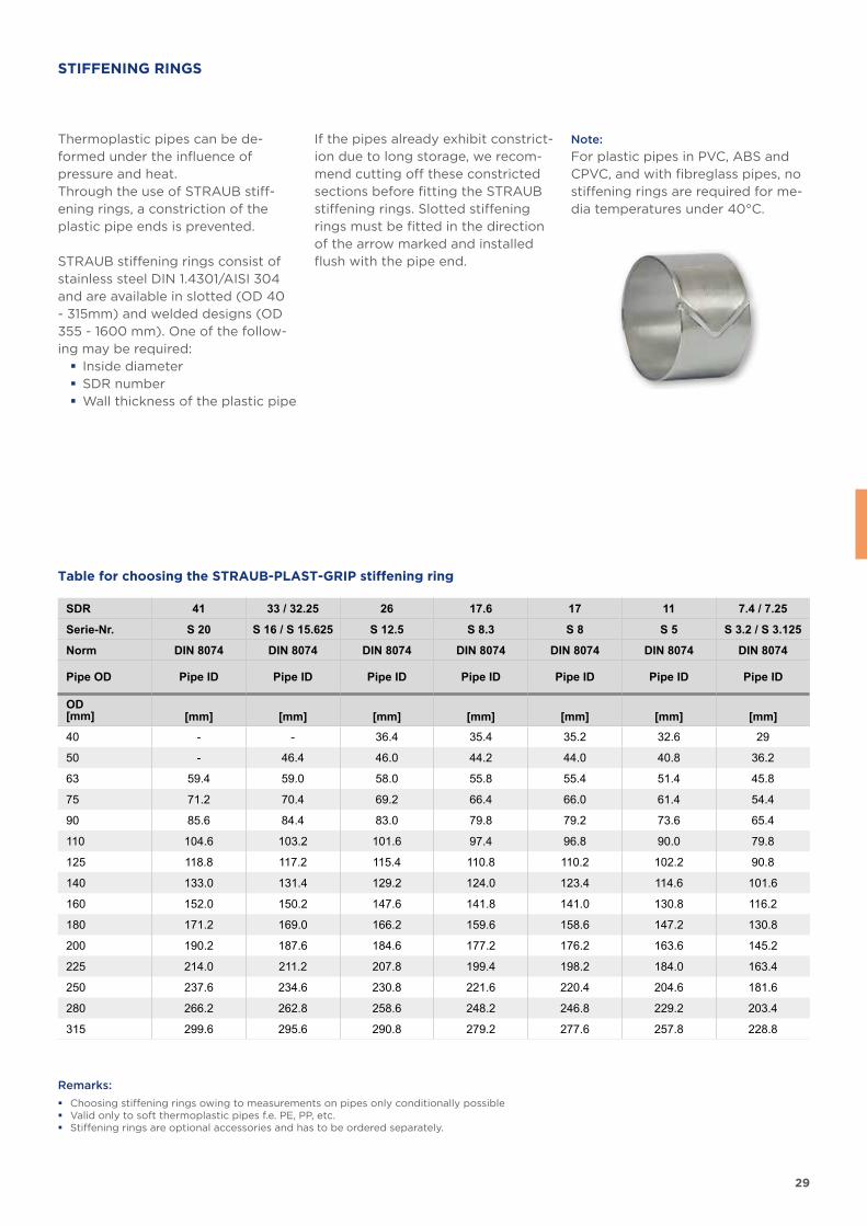
STIFFENING RINGS
Thermoplastic pipes can be de-formed under the influence of pressure and heat. Through the use of STRAUB stiff-ening rings, a constriction of the plastic pipe ends is prevented.
STRAUB stiffening rings consist of stainless steel DIN 1.4301/AISI 304 and are available in slotted (OD 40 - 315mm) and welded designs (OD 355 - 1600 mm). One of the follow-ing may be required:
� Inside diameter � SDR number � Wall thickness of the plastic pipe
If the pipes already exhibit constrict-ion due to long storage, we recom-mend cutting off these constricted sections before fitting the STRAUB stiffening rings. Slotted stiffening rings must be fitted in the direction of the arrow marked and installed flush with the pipe end.
Note:
For plastic pipes in PVC, ABS and CPVC, and with fibreglass pipes, no stiffening rings are required for me-dia temperatures under 40°C.
Table for choosing the STRAUB-PLAST-GRIP stiffening ring
Remarks:
� Choosing stiffening rings owing to measurements on pipes only conditionally possible � Valid only to soft thermoplastic pipes f.e. PE, PP, etc. � Stiffening rings are optional accessories and has to be ordered separately.
SDR 41 33 / 32.25 26 17.6 17 11 7.4 / 7.25
Serie-Nr. S 20 S 16 / S 15.625 S 12.5 S 8.3 S 8 S 5 S 3.2 / S 3.125
Norm DIN 8074 DIN 8074 DIN 8074 DIN 8074 DIN 8074 DIN 8074 DIN 8074
Pipe OD Pipe ID Pipe ID Pipe ID Pipe ID Pipe ID Pipe ID Pipe ID
OD[mm] [mm] [mm] [mm] [mm] [mm] [mm] [mm]
40 - - 36.4 35.4 35.2 32.6 29
50 - 46.4 46.0 44.2 44.0 40.8 36.2
63 59.4 59.0 58.0 55.8 55.4 51.4 45.8
75 71.2 70.4 69.2 66.4 66.0 61.4 54.4
90 85.6 84.4 83.0 79.8 79.2 73.6 65.4
110 104.6 103.2 101.6 97.4 96.8 90.0 79.8
125 118.8 117.2 115.4 110.8 110.2 102.2 90.8
140 133.0 131.4 129.2 124.0 123.4 114.6 101.6
160 152.0 150.2 147.6 141.8 141.0 130.8 116.2
180 171.2 169.0 166.2 159.6 158.6 147.2 130.8
200 190.2 187.6 184.6 177.2 176.2 163.6 145.2
225 214.0 211.2 207.8 199.4 198.2 184.0 163.4
250 237.6 234.6 230.8 221.6 220.4 204.6 181.6
280 266.2 262.8 258.6 248.2 246.8 229.2 203.4
315 299.6 295.6 290.8 279.2 277.6 257.8 228.8
30
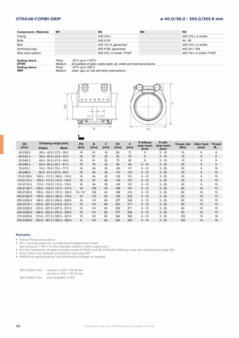
STRAUB-COMBI-GRIP ø 40.0/38.0 - 355.0/355.6 mm
DVB
OD
RC
X
Components / Materials W1 W2 W4 W5Casing AISI 316 L AISI 316 L or similarBolts AISI 4135 A4 - 80Bars AISI 12L14, galvanised AISI 316 L or similarAnchoring rings AISI A106, galvanised AISI 301 / 304Strip insert (option) AISI 316 L or similar / PVDF AISI 316 L or similar / PVDF
Sealing sleeve EPDM
Temp.:Medium:
-20°C up to +100°Call qualities of water, waste water, air, solids and chemical products
Sealing sleeve NBR
Temp.:Medium:
-20°C up to +80°Cwater, gas, oil, fuel and other hydrocarbons
OD[mm]
Clamping range [mm] PN[bar]
B[mm]
C[mm]
DV[mm]
X[mm]
R withoutstrip insert
[mm]
R withstrip insert
[mm]Torque rate
[Nm]Allen head
[mm]Thread
M...Plastic Metal40.0/38.0 39.0 - 40.5 | 37.5 - 39.0 16 61 19 60 73 5 5 - 10 15 6 840.0/42.4 39.0 - 40.5 | 42.0 - 43.5 16 61 20 63 76 5 5 - 10 15 6 850.0/48.3 49.0 - 50.5 | 47.8 - 49.0 16 61 26 70 83 5 5 - 10 15 6 863.0/60.3 62.0 - 64.0 | 59.7 - 61.0 16 76 32 85 98 5 - 10 5 - 25 20 6 875.0/76.1 74.0 - 76.0 | 75.0 - 77.5 16 94 39 100 117 5 - 10 5 - 25 30 8 1090.0/88.9 89.0 - 91.0 | 87.0 - 90.0 16 94 39 118 123 5 - 10 5 - 25 30 8 10
110.0/108.0 109.0 - 111.0 | 106.5 - 110.5 16 94 39 135 151 5 - 10 5 - 25 30 8 10110.0/114.3 109.0 - 111.0 | 112.0 - 116.0 16 97 45 139 157 5 - 10 5 - 25 30 8 10114.3/114.3 113.0 - 115.0 | 112.0 - 116.0 16 94 39 140 157 5 - 10 5 - 25 30 8 10140.0/139.7 139.0 - 142.0 | 137.5 - 141.0 16 109 43 168 191 5 - 15 5 - 30 60 10 12160.0/159.0 159.0 - 162.0 | 157.0 - 160.5 16 / 10 1 109 43 188 210 5 - 15 5 - 30 60 10 12160.0/168.31 159.0 - 162.0 | 166.6 - 170.0 16 110 54 192 222 5 - 10 5 - 30 20 10 12200.0/206.0 198.0 - 202.0 | 204.0 - 208.0 16 141 80 227 246 5 - 15 5 - 35 60 10 12225.0/219.1 223.0 - 227.0 | 216.9 - 221.3 10 141 80 252 271 5 - 15 5 - 35 60 10 12225.0/229.0 223.0 - 227.0 | 227.0 - 231.0 10 141 80 252 271 5 - 15 5 - 35 60 10 12250.0/256.0 248.0 - 252.0 | 253.5 - 258.5 10 141 80 277 296 5 - 15 5 - 35 60 10 12315.0/323.9 313.0 - 317.0 | 320.5 - 327.0 10 141 80 342 365 5 - 15 5 - 35 120 14 16355.0/355.6 353.0 - 357.0 | 352.0 - 359.0 6 141 80 382 405 5 - 15 5 - 35 150 14 16
Remarks:
� Follow fitting instructions � PN = working pressure considering the application loads
Test pressure = PN x 1.5 (for example industry, water supply etc.) � For the installation of pipes of pipes made of HDPE and PP, STRAUB stiffening rings are required (see page 29) � Strip inserts are optional accessories (see page 87) � Additional sealing sleeves and temperature ranges on request
1 160.0/159.0 mm: version in W2 PN 16 bar version in W5 PN 10 bar
160.0/168.3 mm: only available in W5
Typing errors may occur. Technical details are subject to change.
31
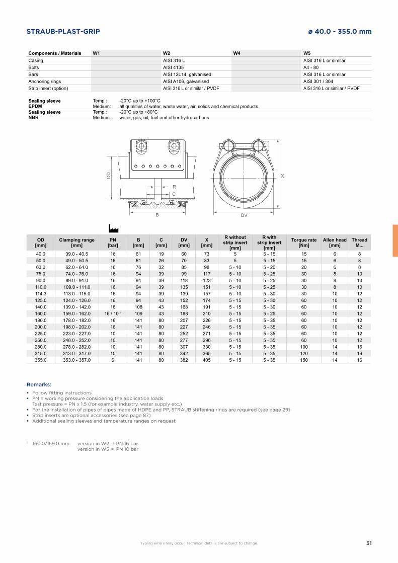
STRAUB-PLAST-GRIP ø 40.0 - 355.0 mm
DVB
OD
RC
X
Components / Materials W1 W2 W4 W5Casing AISI 316 L AISI 316 L or similarBolts AISI 4135 A4 - 80Bars AISI 12L14, galvanised AISI 316 L or similarAnchoring rings AISI A106, galvanised AISI 301 / 304Strip insert (option) AISI 316 L or similar / PVDF AISI 316 L or similar / PVDF
Sealing sleeve EPDM
Temp.:Medium:
-20°C up to +100°Call qualities of water, waste water, air, solids and chemical products
Sealing sleeve NBR
Temp.:Medium:
-20°C up to +80°Cwater, gas, oil, fuel and other hydrocarbons
OD[mm]
Clamping range[mm]
PN[bar]
B[mm]
C[mm]
DV[mm]
X[mm]
R withoutstrip insert
[mm]
R withstrip insert
[mm]Torque rate
[Nm]Allen head
[mm]Thread
M...
40.0 39.0 - 40.5 16 61 19 60 73 5 5 - 15 15 6 850.0 49.0 - 50.5 16 61 26 70 83 5 5 - 15 15 6 863.0 62.0 - 64.0 16 76 32 85 98 5 - 10 5 - 20 20 6 875.0 74.0 - 76.0 16 94 39 99 117 5 - 10 5 - 25 30 8 1090.0 89.0 - 91.0 16 94 39 118 123 5 - 10 5 - 25 30 8 10110.0 109.0 - 111.0 16 94 39 135 151 5 - 10 5 - 25 30 8 10114.3 113.0 - 115.0 16 94 39 139 157 5 - 10 5 - 30 30 10 12125.0 124.0 - 126.0 16 94 43 152 174 5 - 15 5 - 30 60 10 12140.0 139.0 - 142.0 16 108 43 168 191 5 - 15 5 - 30 60 10 12160.0 159.0 - 162.0 16 / 10 1 109 43 188 210 5 - 15 5 - 25 60 10 12180.0 178.0 - 182.0 16 141 80 207 226 5 - 15 5 - 35 60 10 12200.0 198.0 - 202.0 16 141 80 227 246 5 - 15 5 - 35 60 10 12225.0 223.0 - 227.0 10 141 80 252 271 5 - 15 5 - 35 60 10 12250.0 248.0 - 252.0 10 141 80 277 296 5 - 15 5 - 35 60 10 12280.0 278.0 - 282.0 10 141 80 307 330 5 - 15 5 - 35 100 14 16315.0 313.0 - 317.0 10 141 80 342 365 5 - 15 5 - 35 120 14 16355.0 353.0 - 357.0 6 141 80 382 405 5 - 15 5 - 35 150 14 16
Remarks:
� Follow fitting instructions � PN = working pressure considering the application loads
Test pressure = PN x 1.5 (for example industry, water supply etc.) � For the installation of pipes of pipes made of HDPE and PP, STRAUB stiffening rings are required (see page 29) � Strip inserts are optional accessories (see page 87) � Additional sealing sleeves and temperature ranges on request
1 160.0/159.0 mm: version in W2 PN 16 bar version in W5 PN 10 bar
Typing errors may occur. Technical details are subject to change.
32
STRAUB-GRIP
FITTING INSTRUCTION
33
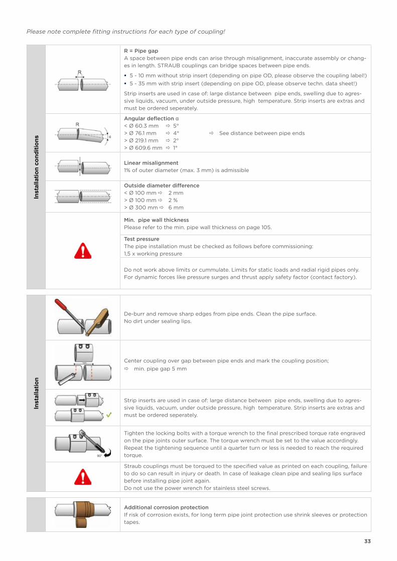
Please note complete fitting instructions for each type of coupling!In
stal
latio
n co
nditi
ons
R = Pipe gap
A space between pipe ends can arise through misalignment, inaccurate assembly or chang-
es in length. STRAUB couplings can bridge spaces between pipe ends.
� 5 - 10 mm without strip insert (depending on pipe OD, please observe the coupling label!)
� 5 - 35 mm with strip insert (depending on pipe OD, please observe techn. data sheet!)
Strip inserts are used in case of: large distance between pipe ends, swelling due to agres-
sive liquids, vacuum, under outside pressure, high temperature. Strip inserts are extras and
must be ordered seperately.
Angular deflection α< Ø 60.3 mm 5°
> Ø 76.1 mm 4° See distance between pipe ends
> Ø 219.1 mm 2°
> Ø 609.6 mm 1°
Linear misalignment
1% of outer diameter (max. 3 mm) is admissible
Outside diameter difference
< Ø 100 mm 2 mm
> Ø 100 mm 2 %
> Ø 300 mm 6 mm
Min. pipe wall thickness
Please refer to the min. pipe wall thickness on page 105.
Test pressure
The pipe installation must be checked as follows before commissioning:
1,5 x working pressure
Do not work above limits or cummulate. Limits for static loads and radial rigid pipes only.
For dynamic forces like pressure surges and thrust apply safety factor (contact factory).
Inst
alla
tion
De-burr and remove sharp edges from pipe ends. Clean the pipe surface.
No dirt under sealing lips.
Center coupling over gap between pipe ends and mark the coupling position;
min. pipe gap 5 mm
Strip inserts are used in case of: large distance between pipe ends, swelling due to agres-
sive liquids, vacuum, under outside pressure, high temperature. Strip inserts are extras and
must be ordered seperately.
Tighten the locking bolts with a torque wrench to the final prescribed torque rate engraved
on the pipe joints outer surface. The torque wrench must be set to the value accordingly.
Repeat the tightening sequence until a quarter turn or less is needed to reach the required
torque.
Straub couplings must be torqued to the specified value as printed on each coupling, failure
to do so can result in injury or death. In case of leakage clean pipe and sealing lips surface
before installing pipe joint again.
Do not use the power wrench for stainless steel screws.
Additional corrosion protection
If risk of corrosion exists, for long term pipe joint protection use shrink sleeves or protection
tapes.
34
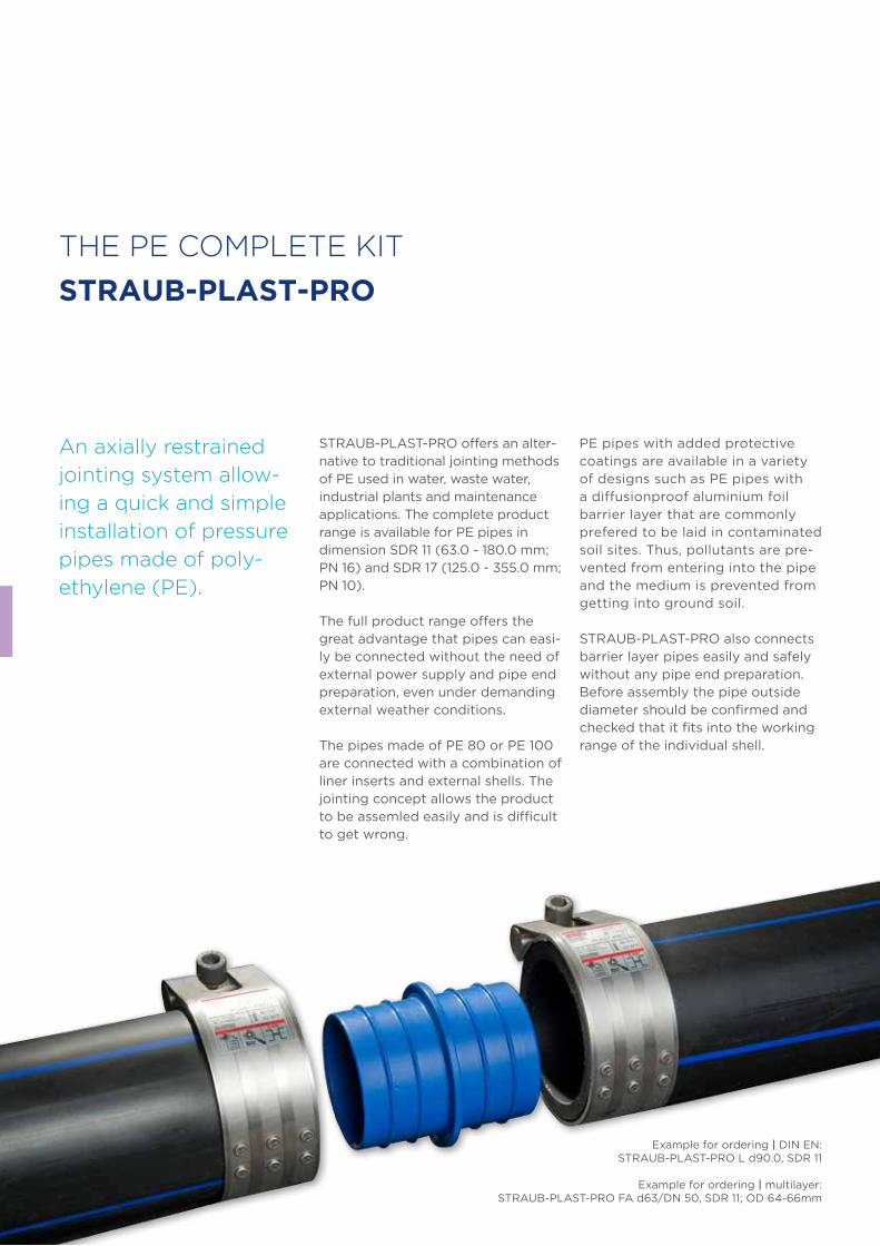
THE PE COMPLETE KIT
STRAUB-PLAST-PRO
An axially restrained
jointing system allow-
ing a quick and simple
installation of pressure
pipes made of poly-
ethylene (PE).
STRAUB-PLAST-PRO offers an alter-native to traditional jointing methods of PE used in water, waste water, industrial plants and maintenance applications. The complete product range is available for PE pipes in dimension SDR 11 (63.0 - 180.0 mm; PN 16) and SDR 17 (125.0 - 355.0 mm; PN 10).
The full product range offers the great advantage that pipes can easi-ly be connected without the need of external power supply and pipe end preparation, even under demanding external weather conditions.
The pipes made of PE 80 or PE 100 are connected with a combination of liner inserts and external shells. The jointing concept allows the product to be assemled easily and is difficult to get wrong.
PE pipes with added protective coatings are available in a variety of designs such as PE pipes with a diffusionproof aluminium foil barrier layer that are commonly prefered to be laid in contaminated soil sites. Thus, pollutants are pre-vented from entering into the pipe and the medium is prevented from getting into ground soil.
STRAUB-PLAST-PRO also connects barrier layer pipes easily and safely without any pipe end preparation. Before assembly the pipe outside diameter should be confirmed and checked that it fits into the working range of the individual shell.
Example for ordering | DIN EN:STRAUB-PLAST-PRO L d90.0, SDR 11
Example for ordering | multilayer:STRAUB-PLAST-PRO FA d63/DN 50, SDR 11; OD 64-66mm
35
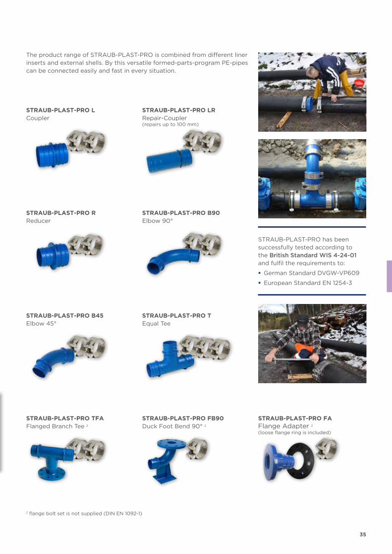
STRAUB-PLAST-PRO LCoupler
STRAUB-PLAST-PRO LRRepair-Coupler(repairs up to 100 mm)
STRAUB-PLAST-PRO RReducer
STRAUB-PLAST-PRO B90Elbow 90°
STRAUB-PLAST-PRO B45Elbow 45°
STRAUB-PLAST-PRO TEqual Tee
STRAUB-PLAST-PRO TFAFlanged Branch Tee 2
STRAUB-PLAST-PRO FB90Duck Foot Bend 90° 2
STRAUB-PLAST-PRO FAFlange Adapter 2
(loose flange ring is included)
The product range of STRAUB-PLAST-PRO is combined from different liner inserts and external shells. By this versatile formed-parts-program PE-pipes can be connected easily and fast in every situation.
STRAUB-PLAST-PRO has been successfully tested according to the British Standard WIS 4-24-01 and fulfil the requirements to:
� German Standard DVGW-VP609
� European Standard EN 1254-3
2 flange bolt set is not supplied (DIN EN 1092-1)
36
DV YDV Y
SDR 11
SDR 17
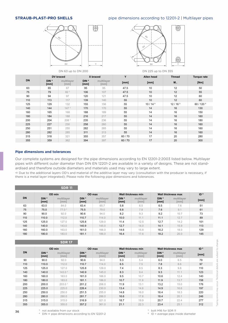
STRAUB-PLAST-PRO SHELLS pipe dimensions according to 12201-2 | Multilayer pipes
DN 63 up to DN 200 DN 225 up to DN 355
DNDV braced X braced Y Allen head Thread Torque rate
DIN 4
[mm]multilayer
[mm]DIN 4
[mm]multilayer
[mm] [mm] [mm] M.. [Nm]
63 65 67 95 95 47.5 10 12 5075 79 82 3 106 107 47.5 10 12 5590 94 97 120 121 47.5 10 12 60110 113 117 139 140 55 10 12 60125 129 132 155 156 55 10 / 14 5 12 / 16 5 60 / 120 5
140 144 147 3 170 170 55 14 16 130160 165 168 188 189 55 14 16 150180 184 188 216 217 55 14 16 160200 204 208 3 235 236 55 14 16 180225 227 230 258 260 55 14 16 160250 251 255 282 285 55 14 16 160280 282 285 311 313 55 14 16 160315 318 321 355 357 60 / 70 17 20 280355 359 362 394 397 60 / 70 17 20 300
DNOD min OD max Wall thickness min Wall thickness max ID 6
DIN 4
[mm]multilayer
[mm]DIN 4
[mm]multilayer
[mm]DIN 4
[mm]multilayer
[mm]DIN 4
[mm]multilayer
[mm] [mm]
63 63.0 64.0 63.4 65.7 5.8 6.5 6.5 7.6 5175 75.0 77.0 3 75.5 79.0 6.8 7.8 7.6 9.1 6190 90.0 92.0 90.6 94.0 8.2 9.3 9.2 10.7 73110 110.0 112.0 110.7 114.0 10.0 11.1 11.1 12.7 89125 125.0 127.0 125.8 129.0 11.4 12.5 12.7 14.2 101140 140.0 143.0 140.9 145.0 12.7 14.0 14.1 15.9 113160 160.0 163.0 161.0 166.0 14.6 15.8 16.2 18.0 129180 180.0 183.0 181.1 186.0 16.4 17.6 18.2 20.0 145
DNOD min OD max Wall thickness min Wall thickness max ID 6
DIN 4
[mm]multilayer
[mm]DIN 4
[mm]multilayer
[mm]DIN 4
[mm]multilayer
[mm]DIN 4
[mm]multilayer
[mm] [mm]
90 90.0 92.0 90.6 94.0 5.3 5.4 6.0 6.5 79110 110.0 112.0 110.7 114.0 6.5 7.5 7.8 8.6 97125 125.0 127.0 125.8 129.0 7.4 8.5 8.3 9.8 110140 140.0 143.0 3 140.9 145.0 8.3 9.4 9.3 11.1 123160 160.0 163.0 161.0 166.0 9.5 10.7 10.6 12.4 140180 180.0 183.0 181.1 186.0 10.7 11.9 11.9 13.7 158200 200.0 203.0 3 201.2 206.0 11.9 13.1 13.2 15.0 176225 225.0 225.0 226.4 230.0 13.4 14.6 14.9 16.6 197250 250.0 250.0 251.5 255.0 14.8 16.0 16.4 18.3 220280 280.0 280.0 281.7 286.0 16.6 17.8 18.4 20.1 246315 315.0 315.0 316.9 321.0 18.7 19.9 20.7 22.4 277355 355.0 355.0 357.2 361.0 21.1 22.3 23.4 25.1 312
Pipe dimensions and tolerances
Our complete systems are designed for the pipe dimensions according to EN 12201-2:2003 listed below. Multilayer pipes with different outer diameter than DIN EN 12201-2 are available in a variety of designs. These are not stand-ardised and therefore outside diameters and materials used may vary to large extent. Due to the additional layers OD‘s and material of the additive layer may vary (consultation with the producer is necessary, if there is a metal layer integrated); Please note the following pipe dimensions and tolerances.
3 not available from our stock4 DIN pipe dimensions according to EN 12201-2
5 bolt M16 for SDR 116 ID = average pipe inside diameter
Typ
ing
err
ors
may o
ccu
r. T
ech
nic
al d
eta
ils a
re s
ub
ject
to c
han
ge.
37
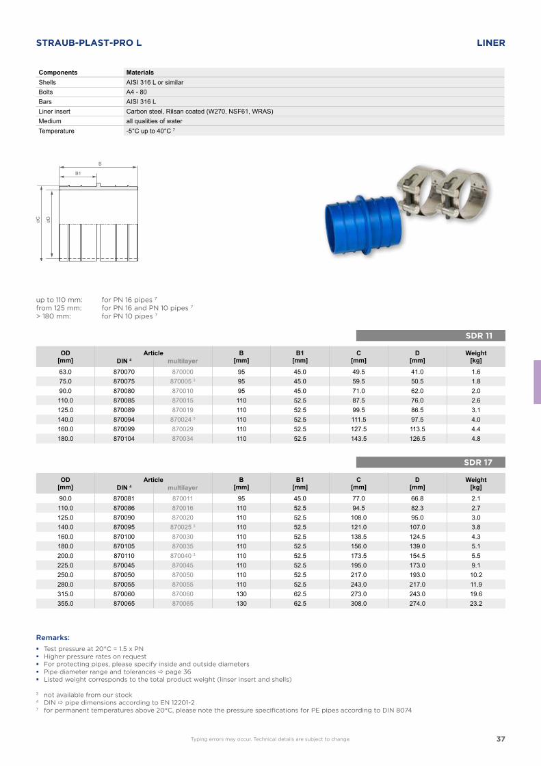
SDR 11
SDR 17
B
B1
STRAUB-PLAST-PRO L LINER
Components MaterialsShells AISI 316 L or similarBolts A4 - 80Bars AISI 316 LLiner insert Carbon steel, Rilsan coated (W270, NSF61, WRAS)Medium all qualities of waterTemperature -5°C up to 40°C 7
up to 110 mm: for PN 16 pipes 7
from 125 mm: for PN 16 and PN 10 pipes 7
> 180 mm: for PN 10 pipes 7
OD[mm]
Article B[mm]
B1[mm]
C[mm]
D[mm]
Weight[kg]DIN 4 multilayer
63.0 870070 870000 95 45.0 49.5 41.0 1.675.0 870075 870005 3 95 45.0 59.5 50.5 1.890.0 870080 870010 95 45.0 71.0 62.0 2.0110.0 870085 870015 110 52.5 87.5 76.0 2.6125.0 870089 870019 110 52.5 99.5 86.5 3.1140.0 870094 870024 3 110 52.5 111.5 97.5 4.0160.0 870099 870029 110 52.5 127.5 113.5 4.4180.0 870104 870034 110 52.5 143.5 126.5 4.8
OD[mm]
Article B[mm]
B1[mm]
C[mm]
D[mm]
Weight[kg]DIN 4 multilayer
90.0 870081 870011 95 45.0 77.0 66.8 2.1110.0 870086 870016 110 52.5 94.5 82.3 2.7125.0 870090 870020 110 52.5 108.0 95.0 3.0140.0 870095 870025 3 110 52.5 121.0 107.0 3.8160.0 870100 870030 110 52.5 138.5 124.5 4.3180.0 870105 870035 110 52.5 156.0 139.0 5.1200.0 870110 870040 3 110 52.5 173.5 154.5 5.5225.0 870045 870045 110 52.5 195.0 173.0 9.1250.0 870050 870050 110 52.5 217.0 193.0 10.2280.0 870055 870055 110 52.5 243.0 217.0 11.9315.0 870060 870060 130 62.5 273.0 243.0 19.6355.0 870065 870065 130 62.5 308.0 274.0 23.2
Remarks:
� Test pressure at 20°C = 1.5 x PN � Higher pressure rates on request � For protecting pipes, please specify inside and outside diameters � Pipe diameter range and tolerances page 36 � Listed weight corresponds to the total product weight (linser insert and shells)
Typing errors may occur. Technical details are subject to change.
3 not available from our stock4 DIN pipe dimensions according to EN 12201-27 for permanent temperatures above 20°C, please note the pressure specifications for PE pipes according to DIN 8074
38
B
B1
SDR 11
SDR 17
8 O-Ring
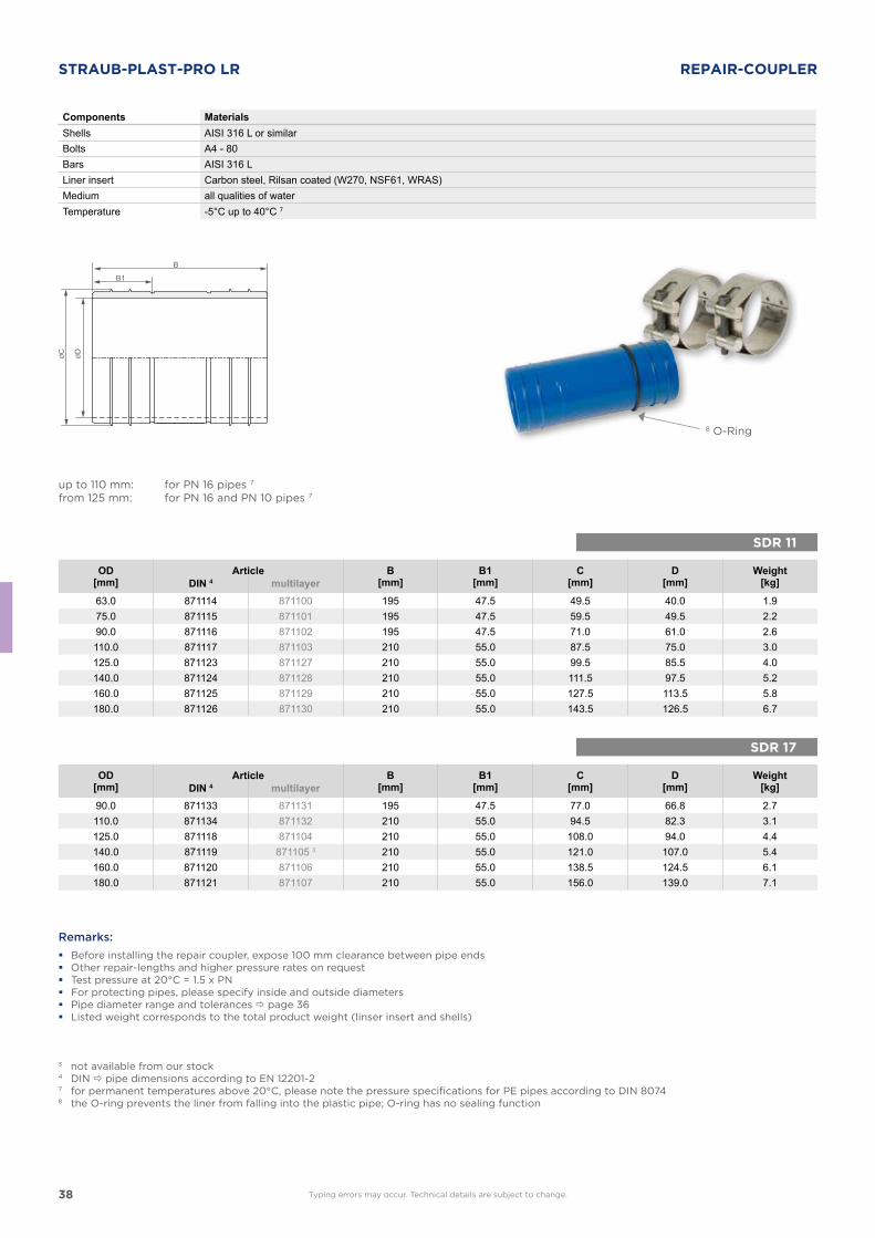
STRAUB-PLAST-PRO LR REPAIR-COUPLER
Components MaterialsShells AISI 316 L or similarBolts A4 - 80Bars AISI 316 LLiner insert Carbon steel, Rilsan coated (W270, NSF61, WRAS)Medium all qualities of waterTemperature -5°C up to 40°C 7
OD[mm]
Article B[mm]
B1[mm]
C[mm]
D[mm]
Weight[kg]DIN 4 multilayer
63.0 871114 871100 195 47.5 49.5 40.0 1.975.0 871115 871101 195 47.5 59.5 49.5 2.290.0 871116 871102 195 47.5 71.0 61.0 2.6110.0 871117 871103 210 55.0 87.5 75.0 3.0125.0 871123 871127 210 55.0 99.5 85.5 4.0140.0 871124 871128 210 55.0 111.5 97.5 5.2160.0 871125 871129 210 55.0 127.5 113.5 5.8180.0 871126 871130 210 55.0 143.5 126.5 6.7
OD[mm]
Article B[mm]
B1[mm]
C[mm]
D[mm]
Weight[kg]DIN 4 multilayer
90.0 871133 871131 195 47.5 77.0 66.8 2.7110.0 871134 871132 210 55.0 94.5 82.3 3.1125.0 871118 871104 210 55.0 108.0 94.0 4.4140.0 871119 871105 3 210 55.0 121.0 107.0 5.4160.0 871120 871106 210 55.0 138.5 124.5 6.1180.0 871121 871107 210 55.0 156.0 139.0 7.1
Remarks:
� Before installing the repair coupler, expose 100 mm clearance between pipe ends � Other repair-lengths and higher pressure rates on request � Test pressure at 20°C = 1.5 x PN � For protecting pipes, please specify inside and outside diameters � Pipe diameter range and tolerances page 36 � Listed weight corresponds to the total product weight (linser insert and shells)
up to 110 mm: for PN 16 pipes 7
from 125 mm: for PN 16 and PN 10 pipes 7
Typing errors may occur. Technical details are subject to change.
3 not available from our stock4 DIN pipe dimensions according to EN 12201-27 for permanent temperatures above 20°C, please note the pressure specifications for PE pipes according to DIN 80748 the O-ring prevents the liner from falling into the plastic pipe; O-ring has no sealing function
39
SDR 11
SDR 17
B
B1
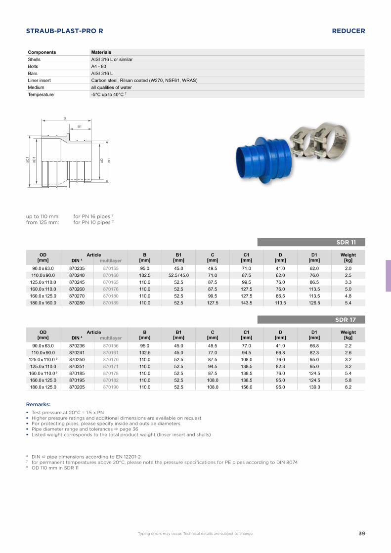
STRAUB-PLAST-PRO R REDUCER
Components MaterialsShells AISI 316 L or similarBolts A4 - 80Bars AISI 316 LLiner insert Carbon steel, Rilsan coated (W270, NSF61, WRAS)Medium all qualities of waterTemperature -5°C up to 40°C 7
OD[mm]
Article B[mm]
B1[mm]
C[mm]
C1[mm]
D[mm]
D1[mm]
Weight[kg]DIN 4 multilayer
90.0 x 63.0 870235 870155 95.0 45.0 49.5 71.0 41.0 62.0 2.0110.0 x 90.0 870240 870160 102.5 52.5 / 45.0 71.0 87.5 62.0 76.0 2.5
125.0 x 110.0 870245 870165 110.0 52.5 87.5 99.5 76.0 86.5 3.3160.0 x 110.0 870260 870176 110.0 52.5 87.5 127.5 76.0 113.5 5.0160.0 x 125.0 870270 870180 110.0 52.5 99.5 127.5 86.5 113.5 4.8180.0 x 160.0 870280 870189 110.0 52.5 127.5 143.5 113.5 126.5 5.4
Remarks:
� Test pressure at 20°C = 1.5 x PN � Higher pressure ratings and additional dimensions are available on request � For protecting pipes, please specify inside and outside diameters � Pipe diameter range and tolerances page 36 � Listed weight corresponds to the total product weight (linser insert and shells)
4 DIN pipe dimensions according to EN 12201-27 for permanent temperatures above 20°C, please note the pressure specifications for PE pipes according to DIN 80749 OD 110 mm in SDR 11
up to 110 mm: for PN 16 pipes 7
from 125 mm: for PN 10 pipes 7
OD[mm]
Article B[mm]
B1[mm]
C[mm]
C1[mm]
D[mm]
D1[mm]
Weight[kg]DIN 4 multilayer
90.0 x 63.0 870236 870156 95.0 45.0 49.5 77.0 41.0 66.8 2.2110.0 x 90.0 870241 870161 102.5 45.0 77.0 94.5 66.8 82.3 2.6
125.0 x 110.0 9 870250 870170 110.0 52.5 87.5 108.0 76.0 95.0 3.2125.0 x 110.0 870251 870171 110.0 52.5 94.5 138.5 82.3 95.0 3.2160.0 x 110.0 9 870185 870178 110.0 52.5 87.5 138.5 76.0 124.5 5.4160.0 x 125.0 870195 870182 110.0 52.5 108.0 138.5 95.0 124.5 5.8180.0 x 125.0 870205 870190 110.0 52.5 108.0 156.0 95.0 139.0 6.2
Typing errors may occur. Technical details are subject to change.
40
SDR 11
SDR 17
HB1
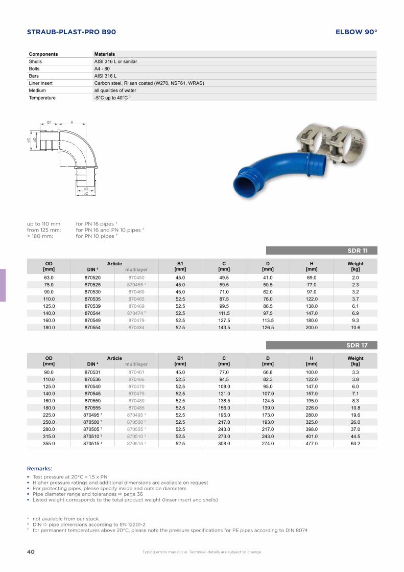
STRAUB-PLAST-PRO B90 ELBOW 90°
Components MaterialsShells AISI 316 L or similarBolts A4 - 80Bars AISI 316 LLiner insert Carbon steel, Rilsan coated (W270, NSF61, WRAS)Medium all qualities of waterTemperature -5°C up to 40°C 7
up to 110 mm: for PN 16 pipes 7
from 125 mm: for PN 16 and PN 10 pipes 7
> 180 mm: for PN 10 pipes 7
OD[mm]
Article B1[mm]
C[mm]
D[mm]
H[mm]
Weight[kg]DIN 4 multilayer
63.0 870520 870450 45.0 49.5 41.0 69.0 2.075.0 870525 870455 3 45.0 59.5 50.5 77.0 2.390.0 870530 870460 45.0 71.0 62.0 97.0 3.2110.0 870535 870465 52.5 87.5 76.0 122.0 3.7125.0 870539 870469 52.5 99.5 86.5 138.0 6.1140.0 870544 870474 3 52.5 111.5 97.5 147.0 6.9160.0 870549 870479 52.5 127.5 113.5 180.0 9.3180.0 870554 870484 52.5 143.5 126.5 200.0 10.6
OD[mm]
Article B1[mm]
C[mm]
D[mm]
H[mm]
Weight[kg]DIN 4 multilayer
90.0 870531 870461 45.0 77.0 66.8 100.0 3.3110.0 870536 870466 52.5 94.5 82.3 122.0 3.8125.0 870540 870470 52.5 108.0 95.0 147.0 6.0140.0 870545 870475 52.5 121.0 107.0 157.0 7.1160.0 870550 870480 52.5 138.5 124.5 195.0 8.3180.0 870555 870485 52.5 156.0 139.0 226.0 10.8225.0 870495 3 870495 3 52.5 195.0 173.0 280.0 19.6250.0 870500 3 870500 3 52.5 217.0 193.0 325.0 26.0280.0 870505 3 870505 3 52.5 243.0 217.0 398.0 37.0315.0 870510 3 870510 3 52.5 273.0 243.0 401.0 44.5355.0 870515 3 870515 3 52.5 308.0 274.0 477.0 63.2
Remarks:
� Test pressure at 20°C = 1.5 x PN � Higher pressure ratings and additional dimensions are available on request � For protecting pipes, please specify inside and outside diameters � Pipe diameter range and tolerances page 36 � Listed weight corresponds to the total product weight (linser insert and shells)
3 not available from our stock4 DIN pipe dimensions according to EN 12201-27 for permanent temperatures above 20°C, please note the pressure specifications for PE pipes according to DIN 8074
Typing errors may occur. Technical details are subject to change.
41
HB1
SDR 11
SDR 17
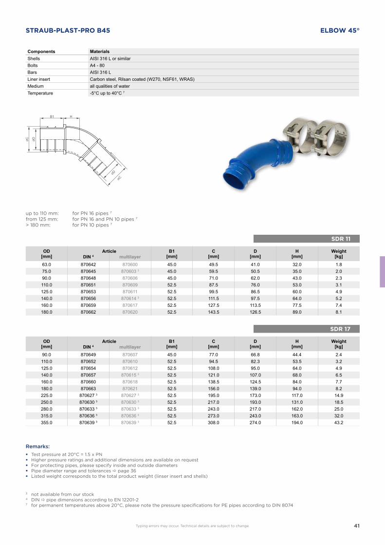
STRAUB-PLAST-PRO B45 ELBOW 45°
Components MaterialsShells AISI 316 L or similarBolts A4 - 80Bars AISI 316 LLiner insert Carbon steel, Rilsan coated (W270, NSF61, WRAS)Medium all qualities of waterTemperature -5°C up to 40°C 7
up to 110 mm: for PN 16 pipes 7
from 125 mm: for PN 16 and PN 10 pipes 7
> 180 mm: for PN 10 pipes 7
OD[mm]
Article B1[mm]
C[mm]
D[mm]
H[mm]
Weight[kg]DIN 4 multilayer
63.0 870642 870600 45.0 49.5 41.0 32.0 1.875.0 870645 870603 3 45.0 59.5 50.5 35.0 2.090.0 870648 870606 45.0 71.0 62.0 43.0 2.3110.0 870651 870609 52.5 87.5 76.0 53.0 3.1125.0 870653 870611 52.5 99.5 86.5 60.0 4.9140.0 870656 870614 3 52.5 111.5 97.5 64.0 5.2160.0 870659 870617 52.5 127.5 113.5 77.5 7.4180.0 870662 870620 52.5 143.5 126.5 89.0 8.1
OD[mm]
Article B1[mm]
C[mm]
D[mm]
H[mm]
Weight[kg]DIN 4 multilayer
90.0 870649 870607 45.0 77.0 66.8 44.4 2.4110.0 870652 870610 52.5 94.5 82.3 53.5 3.2125.0 870654 870612 52.5 108.0 95.0 64.0 4.9140.0 870657 870615 3 52.5 121.0 107.0 68.0 6.5160.0 870660 870618 52.5 138.5 124.5 84.0 7.7180.0 870663 870621 52.5 156.0 139.0 94.0 8.2225.0 870627 3 870627 3 52.5 195.0 173.0 117.0 14.9250.0 870630 3 870630 3 52.5 217.0 193.0 131.0 18.5280.0 870633 3 870633 3 52.5 243.0 217.0 162.0 25.0315.0 870636 3 870636 3 52.5 273.0 243.0 163.0 32.0355.0 870639 3 870639 3 52.5 308.0 274.0 194.0 43.2
Remarks:
� Test pressure at 20°C = 1.5 x PN � Higher pressure ratings and additional dimensions are available on request � For protecting pipes, please specify inside and outside diameters � Pipe diameter range and tolerances page 36 � Listed weight corresponds to the total product weight (linser insert and shells)
3 not available from our stock4 DIN pipe dimensions according to EN 12201-27 for permanent temperatures above 20°C, please note the pressure specifications for PE pipes according to DIN 8074
Typing errors may occur. Technical details are subject to change.
42
SDR 11
SDR 17
BB1
B1
H
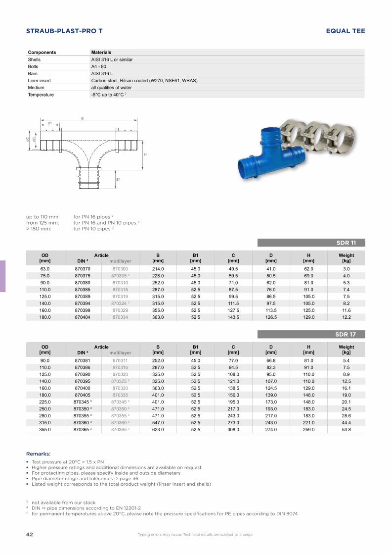
STRAUB-PLAST-PRO T EQUAL TEE
Components MaterialsShells AISI 316 L or similarBolts A4 - 80Bars AISI 316 LLiner insert Carbon steel, Rilsan coated (W270, NSF61, WRAS)Medium all qualities of waterTemperature -5°C up to 40°C 7
up to 110 mm: for PN 16 pipes 7
from 125 mm: for PN 16 and PN 10 pipes 7
> 180 mm: for PN 10 pipes 7
OD[mm]
Article B[mm]
B1[mm]
C[mm]
D[mm]
H[mm]
Weight[kg]DIN 4 multilayer
63.0 870370 870300 214.0 45.0 49.5 41.0 62.0 3.075.0 870375 870305 3 228.0 45.0 59.5 50.5 69.0 4.090.0 870380 870310 252.0 45.0 71.0 62.0 81.0 5.3110.0 870385 870315 287.0 52.5 87.5 76.0 91.0 7.4125.0 870389 870319 315.0 52.5 99.5 86.5 105.0 7.5140.0 870394 870324 3 315.0 52.5 111.5 97.5 105.0 8.2160.0 870399 870329 355.0 52.5 127.5 113.5 125.0 11.6180.0 870404 870334 363.0 52.5 143.5 126.5 129.0 12.2
OD[mm]
Article B[mm]
B1[mm]
C[mm]
D[mm]
H[mm]
Weight[kg]DIN 4 multilayer
90.0 870381 870311 252.0 45.0 77.0 66.8 81.0 5.4110.0 870386 870316 287.0 52.5 94.5 82.3 91.0 7.5125.0 870390 870320 325.0 52.5 108.0 95.0 110.0 8.9140.0 870395 870325 3 325.0 52.5 121.0 107.0 110.0 12.5160.0 870400 870330 363.0 52.5 138.5 124.5 129.0 16.1180.0 870405 870335 401.0 52.5 156.0 139.0 148.0 19.0225.0 870345 3 870345 3 401.0 52.5 195.0 173.0 148.0 20.1250.0 870350 3 870350 3 471.0 52.5 217.0 193.0 183.0 24.5280.0 870355 3 870355 3 471.0 52.5 243.0 217.0 183.0 28.6315.0 870360 3 870360 3 547.0 52.5 273.0 243.0 221.0 44.4355.0 870365 3 870365 3 623.0 52.5 308.0 274.0 259.0 53.8
Remarks:
� Test pressure at 20°C = 1.5 x PN � Higher pressure ratings and additional dimensions are available on request � For protecting pipes, please specify inside and outside diameters � Pipe diameter range and tolerances page 36 � Listed weight corresponds to the total product weight (linser insert and shells)
3 not available from our stock4 DIN pipe dimensions according to EN 12201-27 for permanent temperatures above 20°C, please note the pressure specifications for PE pipes according to DIN 8074
Typing errors may occur. Technical details are subject to change.
43
SDR 11
SDR 17
S
B
B1
ØF
H
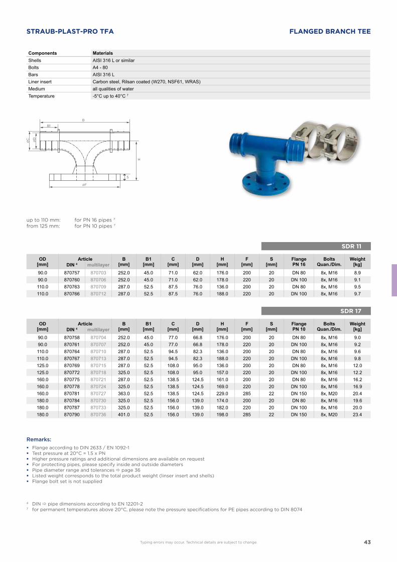
STRAUB-PLAST-PRO TFA FLANGED BRANCH TEE
Components MaterialsShells AISI 316 L or similarBolts A4 - 80Bars AISI 316 LLiner insert Carbon steel, Rilsan coated (W270, NSF61, WRAS)Medium all qualities of waterTemperature -5°C up to 40°C 7
up to 110 mm: for PN 16 pipes 7
from 125 mm: for PN 10 pipes 7
OD[mm]
Article B[mm]
B1[mm]
C[mm]
D[mm]
H[mm]
F[mm]
S[mm]
FlangePN 16
BoltsQuan./Dim.
Weight[kg]DIN 4 multilayer
90.0 870757 870703 252.0 45.0 71.0 62.0 176.0 200 20 DN 80 8x, M16 8.990.0 870760 870706 252.0 45.0 71.0 62.0 178.0 220 20 DN 100 8x, M16 9.1110.0 870763 870709 287.0 52.5 87.5 76.0 136.0 200 20 DN 80 8x, M16 9.5110.0 870766 870712 287.0 52.5 87.5 76.0 188.0 220 20 DN 100 8x, M16 9.7
Remarks:
� Flange according to DIN 2633 / EN 1092-1 � Test pressure at 20°C = 1.5 x PN � Higher pressure ratings and additional dimensions are available on request � For protecting pipes, please specify inside and outside diameters � Pipe diameter range and tolerances page 36 � Listed weight corresponds to the total product weight (linser insert and shells) � Flange bolt set is not supplied
4 DIN pipe dimensions according to EN 12201-27 for permanent temperatures above 20°C, please note the pressure specifications for PE pipes according to DIN 8074
OD[mm]
Article B[mm]
B1[mm]
C[mm]
D[mm]
H[mm]
F[mm]
S[mm]
FlangePN 10
BoltsQuan./Dim.
Weight[kg]DIN 4 multilayer
90.0 870758 870704 252.0 45.0 77.0 66.8 176.0 200 20 DN 80 8x, M16 9.090.0 870761 870707 252.0 45.0 77.0 66.8 178.0 220 20 DN 100 8x, M16 9.2110.0 870764 870710 287.0 52.5 94.5 82.3 136.0 200 20 DN 80 8x, M16 9.6110.0 870767 870713 287.0 52.5 94.5 82.3 188.0 220 20 DN 100 8x, M16 9.8125.0 870769 870715 287.0 52.5 108.0 95.0 136.0 200 20 DN 80 8x, M16 12.0125.0 870772 870718 325.0 52.5 108.0 95.0 157.0 220 20 DN 100 8x, M16 12.2160.0 870775 870721 287.0 52.5 138.5 124.5 161.0 200 20 DN 80 8x, M16 16.2160.0 870778 870724 325.0 52.5 138.5 124.5 169.0 220 20 DN 100 8x, M16 16.9160.0 870781 870727 363.0 52.5 138.5 124.5 229.0 285 22 DN 150 8x, M20 20.4180.0 870784 870730 325.0 52.5 156.0 139.0 174.0 200 20 DN 80 8x, M16 19.6180.0 870787 870733 325.0 52.5 156.0 139.0 182.0 220 20 DN 100 8x, M16 20.0180.0 870790 870736 401.0 52.5 156.0 139.0 198.0 285 22 DN 150 8x, M20 23.4
Typing errors may occur. Technical details are subject to change.
44
SDR 11
SDR 17
J
L
B1
ØF
G
H
S
K
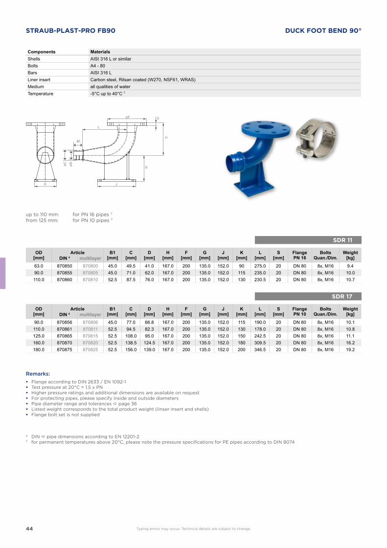
STRAUB-PLAST-PRO FB90 DUCK FOOT BEND 90°
Components MaterialsShells AISI 316 L or similarBolts A4 - 80Bars AISI 316 LLiner insert Carbon steel, Rilsan coated (W270, NSF61, WRAS)Medium all qualities of waterTemperature -5°C up to 40°C 7
up to 110 mm: for PN 16 pipes 7
from 125 mm: for PN 10 pipes 7
OD[mm]
Article B1[mm]
C[mm]
D[mm]
H[mm]
F[mm]
G[mm]
J[mm]
K[mm]
L[mm]
S[mm]
FlangePN 16
BoltsQuan./Dim.
Weight[kg]DIN 4 multilayer
63.0 870850 870800 45.0 49.5 41.0 167.0 200 135.0 152.0 90 275.0 20 DN 80 8x, M16 9.490.0 870855 870805 45.0 71.0 62.0 167.0 200 135.0 152.0 115 235.0 20 DN 80 8x, M16 10.0110.0 870860 870810 52.5 87.5 76.0 167.0 200 135.0 152.0 130 230.5 20 DN 80 8x, M16 10.7
Remarks:
� Flange according to DIN 2633 / EN 1092-1 � Test pressure at 20°C = 1.5 x PN � Higher pressure ratings and additional dimensions are available on request � For protecting pipes, please specify inside and outside diameters � Pipe diameter range and tolerances page 36 � Listed weight corresponds to the total product weight (linser insert and shells) � Flange bolt set is not supplied
4 DIN pipe dimensions according to EN 12201-27 for permanent temperatures above 20°C, please note the pressure specifications for PE pipes according to DIN 8074
OD[mm]
Article B1[mm]
C[mm]
D[mm]
H[mm]
F[mm]
G[mm]
J[mm]
K[mm]
L[mm]
S[mm]
FlangePN 10
BoltsQuan./Dim.
Weight[kg]DIN 4 multilayer
90.0 870856 870806 45.0 77.0 66.8 167.0 200 135.0 152.0 115 190.0 20 DN 80 8x, M16 10.1110.0 870861 870811 52.5 94.5 82.3 167.0 200 135.0 152.0 130 178.0 20 DN 80 8x, M16 10.8125.0 870865 870815 52.5 108.0 95.0 167.0 200 135.0 152.0 150 242.5 20 DN 80 8x, M16 11.1160.0 870870 870820 52.5 138.5 124.5 167.0 200 135.0 152.0 180 309.5 20 DN 80 8x, M16 16.2180.0 870875 870825 52.5 156.0 139.0 167.0 200 135.0 152.0 200 346.5 20 DN 80 8x, M16 19.2
Typing errors may occur. Technical details are subject to change.
45
S
B
B1
SDR 11
SDR 17
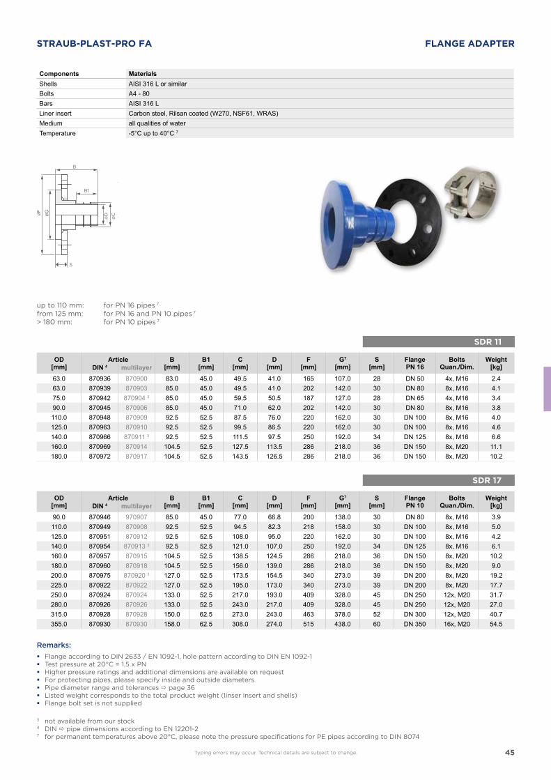
STRAUB-PLAST-PRO FA FLANGE ADAPTER
Components MaterialsShells AISI 316 L or similarBolts A4 - 80Bars AISI 316 LLiner insert Carbon steel, Rilsan coated (W270, NSF61, WRAS)Medium all qualities of waterTemperature -5°C up to 40°C 7
up to 110 mm: for PN 16 pipes 7
from 125 mm: for PN 16 and PN 10 pipes 7
> 180 mm: for PN 10 pipes 7
OD[mm]
Article B[mm]
B1[mm]
C[mm]
D[mm]
F[mm]
G7
[mm]S
[mm]FlangePN 16
BoltsQuan./Dim.
Weight[kg]DIN 4 multilayer
63.0 870936 870900 83.0 45.0 49.5 41.0 165 107.0 28 DN 50 4x, M16 2.463.0 870939 870903 85.0 45.0 49.5 41.0 202 142.0 30 DN 80 8x, M16 4.175.0 870942 870904 3 85.0 45.0 59.5 50.5 187 127.0 28 DN 65 4x, M16 3.490.0 870945 870906 85.0 45.0 71.0 62.0 202 142.0 30 DN 80 8x, M16 3.8110.0 870948 870909 92.5 52.5 87.5 76.0 220 162.0 30 DN 100 8x, M16 4.0125.0 870963 870910 92.5 52.5 99.5 86.5 220 162.0 30 DN 100 8x, M16 4.6140.0 870966 870911 3 92.5 52.5 111.5 97.5 250 192.0 34 DN 125 8x, M16 6.6160.0 870969 870914 104.5 52.5 127.5 113.5 286 218.0 36 DN 150 8x, M20 11.1180.0 870972 870917 104.5 52.5 143.5 126.5 286 218.0 36 DN 150 8x, M20 10.2
Remarks:
� Flange according to DIN 2633 / EN 1092-1, hole pattern according to DIN EN 1092-1 � Test pressure at 20°C = 1.5 x PN � Higher pressure ratings and additional dimensions are available on request � For protecting pipes, please specify inside and outside diameters � Pipe diameter range and tolerances page 36 � Listed weight corresponds to the total product weight (linser insert and shells) � Flange bolt set is not supplied
3 not available from our stock4 DIN pipe dimensions according to EN 12201-27 for permanent temperatures above 20°C, please note the pressure specifications for PE pipes according to DIN 8074
OD[mm]
Article B[mm]
B1[mm]
C[mm]
D[mm]
F[mm]
G7
[mm]S
[mm]FlangePN 10
BoltsQuan./Dim.
Weight[kg]DIN 4 multilayer
90.0 870946 970907 85.0 45.0 77.0 66.8 200 138.0 30 DN 80 8x, M16 3.9110.0 870949 870908 92.5 52.5 94.5 82.3 218 158.0 30 DN 100 8x, M16 5.0125.0 870951 870912 92.5 52.5 108.0 95.0 220 162.0 30 DN 100 8x, M16 4.2140.0 870954 870913 3 92.5 52.5 121.0 107.0 250 192.0 34 DN 125 8x, M16 6.1160.0 870957 870915 104.5 52.5 138.5 124.5 286 218.0 36 DN 150 8x, M20 10.2180.0 870960 870918 104.5 52.5 156.0 139.0 286 218.0 36 DN 150 8x, M20 9.0200.0 870975 870920 3 127.0 52.5 173.5 154.5 340 273.0 39 DN 200 8x, M20 19.2225.0 870922 870922 127.0 52.5 195.0 173.0 340 273.0 39 DN 200 8x, M20 17.7250.0 870924 870924 133.0 52.5 217.0 193.0 409 328.0 45 DN 250 12x, M20 31.7280.0 870926 870926 133.0 52.5 243.0 217.0 409 328.0 45 DN 250 12x, M20 27.0315.0 870928 870928 150.0 62.5 273.0 243.0 463 378.0 52 DN 300 12x, M20 40.7355.0 870930 870930 158.0 62.5 308.0 274.0 515 438.0 60 DN 350 16x, M20 54.5
Typing errors may occur. Technical details are subject to change.
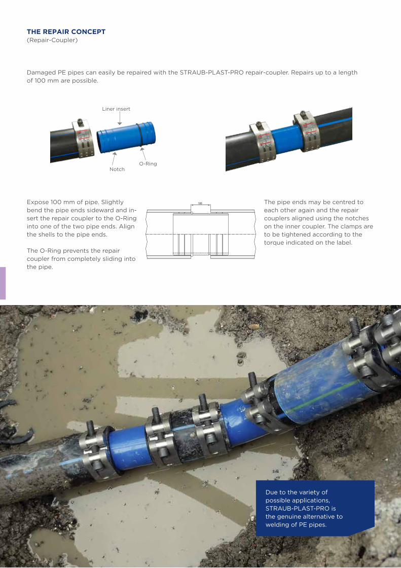
46
100
THE REPAIR CONCEPT(Repair-Coupler)
Due to the variety of possible applications, STRAUB-PLAST-PRO is the genuine alternative to welding of PE pipes.
Damaged PE pipes can easily be repaired with the STRAUB-PLAST-PRO repair-coupler. Repairs up to a length of 100 mm are possible.
Expose 100 mm of pipe. Slightly bend the pipe ends sideward and in-sert the repair coupler to the O-Ring into one of the two pipe ends. Align the shells to the pipe ends.
The O-Ring prevents the repair coupler from completely sliding into the pipe.
The pipe ends may be centred to each other again and the repair couplers aligned using the notches on the inner coupler. The clamps are to be tightened according to the torque indicated on the label.
Liner insert
NotchO-Ring
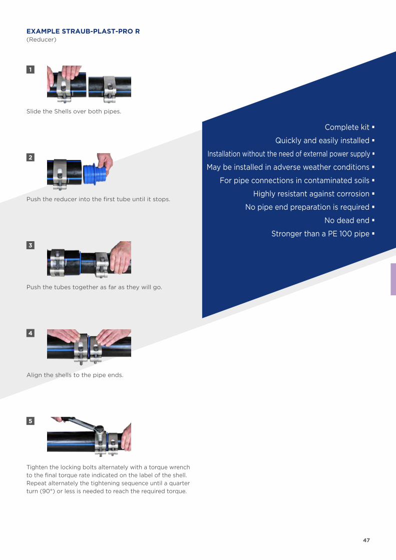
47
1
2
3
5
4
Slide the Shells over both pipes.
Push the reducer into the first tube until it stops.
Push the tubes together as far as they will go.
Tighten the locking bolts alternately with a torque wrench to the final torque rate indicated on the label of the shell. Repeat alternately the tightening sequence until a quarter turn (90°) or less is needed to reach the required torque.
Align the shells to the pipe ends.
EXAMPLE STRAUB-PLAST-PRO R(Reducer)
Complete kit �
Quickly and easily installed �
Installation without the need of external power supply �
May be installed in adverse weather conditions �
For pipe connections in contaminated soils �
Highly resistant against corrosion �
No pipe end preparation is required �
No dead end �
Stronger than a PE 100 pipe �
48
TH
E F
AS
TE
ST
TU
RN
ON
TH
E P
IPE
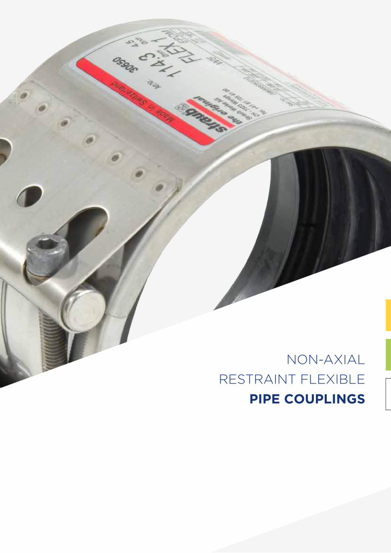
49
NON-AXIAL
RESTRAINT FLEXIBLE
PIPE COUPLINGS
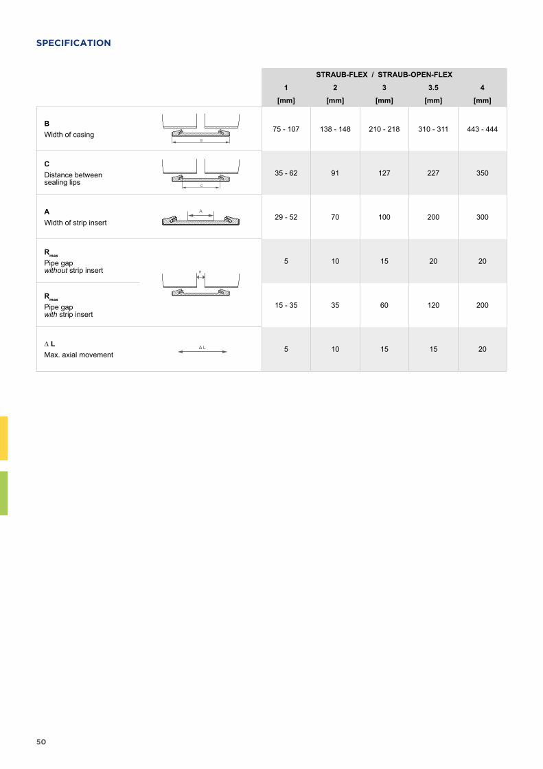
50
SPECIFICATION
STRAUB-FLEX / STRAUB-OPEN-FLEX
1 2 3 3.5 4
[mm] [mm] [mm] [mm] [mm]
BWidth of casing
B
75 - 107 138 - 148 210 - 218 310 - 311 443 - 444
CDistance between sealing lips C
35 - 62 91 127 227 350
AWidth of strip insert
A29 - 52 70 100 200 300
Rmax
Pipe gap without strip insert R
5 10 15 20 20
Rmax
Pipe gap with strip insert
15 - 35 35 60 120 200
∆ LMax. axial movement
Δ L 5 10 15 15 20
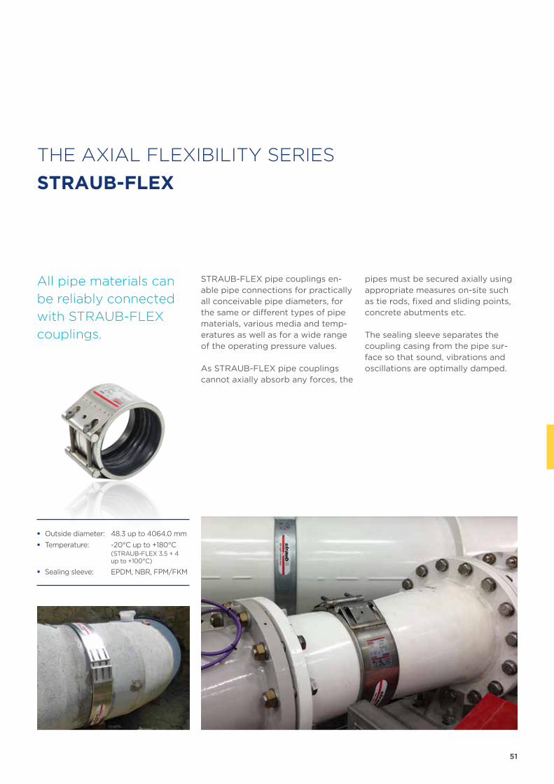
51
THE AXIAL FLEXIBILITY SERIES
STRAUB-FLEX
STRAUB-FLEX pipe couplings en-able pipe connections for practically all conceivable pipe diameters, for the same or different types of pipe materials, various media and temp-eratures as well as for a wide range of the operating pressure values.
As STRAUB-FLEX pipe couplings cannot axially absorb any forces, the
All pipe materials can
be reliably connected
with STRAUB-FLEX
couplings.
pipes must be secured axially using appropriate measures on-site such as tie rods, fixed and sliding points, concrete abutments etc.
The sealing sleeve separates the coupling casing from the pipe sur-face so that sound, vibrations and oscillations are optimally damped.
� Outside diameter: 48.3 up to 4064.0 mm
� Temperature: -20°C up to +180°C (STRAUB-FLEX 3.5 + 4 up to +100°C)
� Sealing sleeve: EPDM, NBR, FPM/FKM
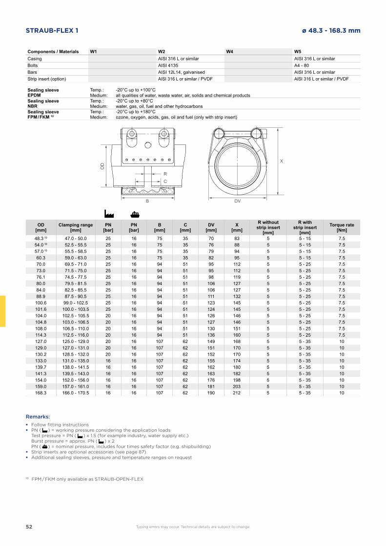
52
STRAUB-FLEX 1 ø 48.3 - 168.3 mm
Components / Materials W1 W2 W4 W5Casing AISI 316 L or similar AISI 316 L or similarBolts AISI 4135 A4 - 80Bars AISI 12L14, galvanised AISI 316 L or similarStrip insert (option) AISI 316 L or similar / PVDF AISI 316 L or similar / PVDF
Sealing sleeve EPDM
Temp.:Medium:
-20°C up to +100°Call qualities of water, waste water, air, solids and chemical products
Sealing sleeve NBR
Temp.:Medium:
-20°C up to +80°Cwater, gas, oil, fuel and other hydrocarbons
Sealing sleeve FPM / FKM 12
Temp.:Medium:
-20°C up to +180°Cozone, oxygen, acids, gas, oil and fuel (only with strip insert)
OD[mm]
Clamping range[mm]
PN[bar]
PN[bar]
B[mm]
C[mm]
DV[mm]
X[mm]
R withoutstrip insert
[mm]
R withstrip insert
[mm]Torque rate
[Nm]
48.3 10 47.0 - 50.0 25 16 75 35 70 83 5 5 - 15 7.554.0 10 52.5 - 55.5 25 16 75 35 76 88 5 5 - 15 7.557.0 10 55.5 - 58.5 25 16 75 35 79 94 5 5 - 15 7.560.3 59.0 - 63.0 25 16 75 35 82 95 5 5 - 15 7.570.0 69.5 - 71.0 25 16 94 51 95 112 5 5 - 25 7.573.0 71.5 - 75.0 25 16 94 51 95 112 5 5 - 25 7.576.1 74.5 - 77.5 25 16 94 51 98 119 5 5 - 25 7.580.0 79.5 - 81.5 25 16 94 51 106 127 5 5 - 25 7.584.0 82.5 - 85.5 25 16 94 51 106 127 5 5 - 25 7.588.9 87.5 - 90.5 25 16 94 51 111 132 5 5 - 25 7.5
100.6 99.0 - 102.5 25 16 94 51 123 145 5 5 - 25 7.5101.6 100.0 - 103.5 25 16 94 51 124 145 5 5 - 25 7.5104.0 102.5 - 105.5 20 16 94 51 126 146 5 5 - 25 7.5104.8 103.0 - 106.5 20 16 94 51 127 146 5 5 - 25 7.5108.0 106.5 - 110.0 20 16 94 51 130 151 5 5 - 25 7.5114.3 112.5 - 116.0 20 16 94 51 136 160 5 5 - 25 7.5127.0 125.0 - 129.0 20 16 107 62 149 168 5 5 - 35 10129.0 127.0 - 131.0 20 16 107 62 151 170 5 5 - 35 10130.2 128.5 - 132.0 20 16 107 62 152 170 5 5 - 35 10133.0 131.0 - 135.0 16 16 107 62 155 174 5 5 - 35 10139.7 138.0 - 141.5 16 16 107 62 162 180 5 5 - 35 10141.3 139.5 - 143.0 16 16 107 62 163 182 5 5 - 35 10154.0 152.0 - 156.0 16 16 107 62 176 198 5 5 - 35 10159.0 157.0 - 161.0 16 16 107 62 181 203 5 5 - 35 10168.3 166.0 - 170.5 16 16 107 62 190 212 5 5 - 35 10
DVB
OD
RC
X
Remarks:
� Follow fitting instructions � PN ( ) = working pressure considering the application loads
Test pressure = PN ( ) x 1.5 (for example industry, water supply etc.) Burst pressure = approx. PN ( ) x 2 PN ( ) = nominal pressure, includes four times safety factor (e.g. shipbuilding) � Strip inserts are optional accessories (see page 87) � Additional sealing sleeves, pressure and temperature ranges on request
10 FPM / FKM only available as STRAUB-OPEN-FLEX
Typing errors may occur. Technical details are subject to change.
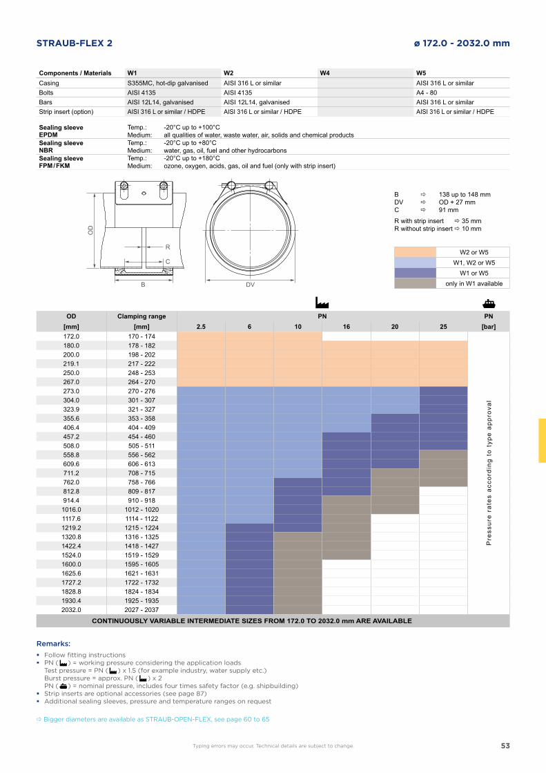
53
STRAUB-FLEX 2 ø 172.0 - 2032.0 mm
DVB
OD
R
C
Components / Materials W1 W2 W4 W5Casing S355MC, hot-dip galvanised AISI 316 L or similar AISI 316 L or similarBolts AISI 4135 AISI 4135 A4 - 80Bars AISI 12L14, galvanised AISI 12L14, galvanised AISI 316 L or similarStrip insert (option) AISI 316 L or similar / HDPE AISI 316 L or similar / HDPE AISI 316 L or similar / HDPE
Sealing sleeve EPDM
Temp.:Medium:
-20°C up to +100°Call qualities of water, waste water, air, solids and chemical products
Sealing sleeve NBR
Temp.:Medium:
-20°C up to +80°Cwater, gas, oil, fuel and other hydrocarbons
Sealing sleeve FPM / FKM
Temp.:Medium:
-20°C up to +180°Cozone, oxygen, acids, gas, oil and fuel (only with strip insert)
OD Clamping range PN PN[mm] [mm] 2.5 6 10 16 20 25 [bar]172.0 170 - 174
Pre
ssur
e ra
tes
acco
rdin
g to
typ
e ap
prov
al
180.0 178 - 182200.0 198 - 202219.1 217 - 222250.0 248 - 253267.0 264 - 270273.0 270 - 276304.0 301 - 307323.9 321 - 327355.6 353 - 358406.4 404 - 409457.2 454 - 460508.0 505 - 511558.8 556 - 562609.6 606 - 613711.2 708 - 715762.0 758 - 766812.8 809 - 817914.4 910 - 9181016.0 1012 - 10201117.6 1114 - 11221219.2 1215 - 12241320.8 1316 - 13251422.4 1418 - 14271524.0 1519 - 15291600.0 1595 - 16051625.6 1621 - 16311727.2 1722 - 17321828.8 1824 - 18341930.4 1925 - 19352032.0 2027 - 2037
CONTINUOUSLY VARIABLE INTERMEDIATE SIZES FROM 172.0 TO 2032.0 mm ARE AVAILABLE
Remarks:
� Follow fitting instructions � PN ( ) = working pressure considering the application loads
Test pressure = PN ( ) x 1.5 (for example industry, water supply etc.) Burst pressure = approx. PN ( ) x 2 PN ( ) = nominal pressure, includes four times safety factor (e.g. shipbuilding) � Strip inserts are optional accessories (see page 87) � Additional sealing sleeves, pressure and temperature ranges on request
B 138 up to 148 mmDV OD + 27 mmC 91 mm
R with strip insert 35 mmR without strip insert 10 mm
Typing errors may occur. Technical details are subject to change.
W2 or W5W1, W2 or W5
W1 or W5only in W1 available
Bigger diameters are available as STRAUB-OPEN-FLEX, see page 60 to 65
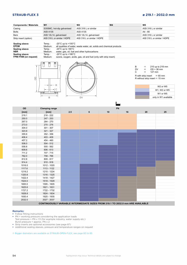
54
STRAUB-FLEX 3 ø 219.1 - 2032.0 mm
DVB
OD
R
C
Components / Materials W1 W2 W4 W5Casing S355MC, hot-dip galvanised AISI 316 L or similar AISI 316 L or similarBolts AISI 4135 AISI 4135 A4 - 80Bars AISI 12L14, galvanised AISI 12L14, galvanised AISI 316 L or similarStrip insert (option) AISI 316 L or similar / HDPE AISI 316 L or similar / HDPE AISI 316 L or similar / HDPE
Sealing sleeve EPDM
Temp.:Medium:
-20°C up to +100°Call qualities of water, waste water, air, solids and chemical products
Sealing sleeve NBR
Temp.:Medium:
-20°C up to +80°Cwater, gas, oil, fuel and other hydrocarbons
Sealing sleeve FPM / FKM (on request)
Temp.:Medium:
-20°C up to +180°Cozone, oxygen, acids, gas, oil and fuel (only with strip insert)
OD Clamping range PN[mm] [mm] 2.5 6 10 16 20 25219.1 216 - 222250.0 247 - 253267.0 264 - 270273.0 270 - 276304.0 301 - 307323.9 321 - 327355.6 352 - 358406.4 403 - 409457.2 454 - 460508.0 504 - 512558.8 555 - 562609.6 606 - 613711.2 707 - 715762.0 758 - 766812.8 809 - 817914.4 910 - 9181016.0 1012 - 10201117.6 1113 - 11221219.2 1215 - 12241320.8 1316 - 13251422.4 1418 - 14271524.0 1519 - 15291600.0 1595 - 16051625.6 1621 - 16311727.2 1722 - 17321828.8 1824 - 18341930.4 1925 - 19352032.0 2027 - 2037
CONTINUOUSLY VARIABLE INTERMEDIATE SIZES FROM 219.1 TO 2032.0 mm ARE AVAILABLE
Remarks: � Follow fitting instructions � PN = working pressure considering the application loads
Test pressure = PN x 1.5 (for example industry, water supply etc.) Burst pressure = approx. PN x 2 � Strip inserts are optional accessories (see page 87) � Additional sealing sleeves, pressure and temperature ranges on request
Typing errors may occur. Technical details are subject to change.
W2 or W5W1, W2 or W5
W1 or W5only in W1 available
B 210 up to 218 mmDV OD + 38 mmC 127 mm
R with strip insert 60 mmR without strip insert 15 mm
Bigger diameters are available as STRAUB-OPEN-FLEX, see page 60 to 65
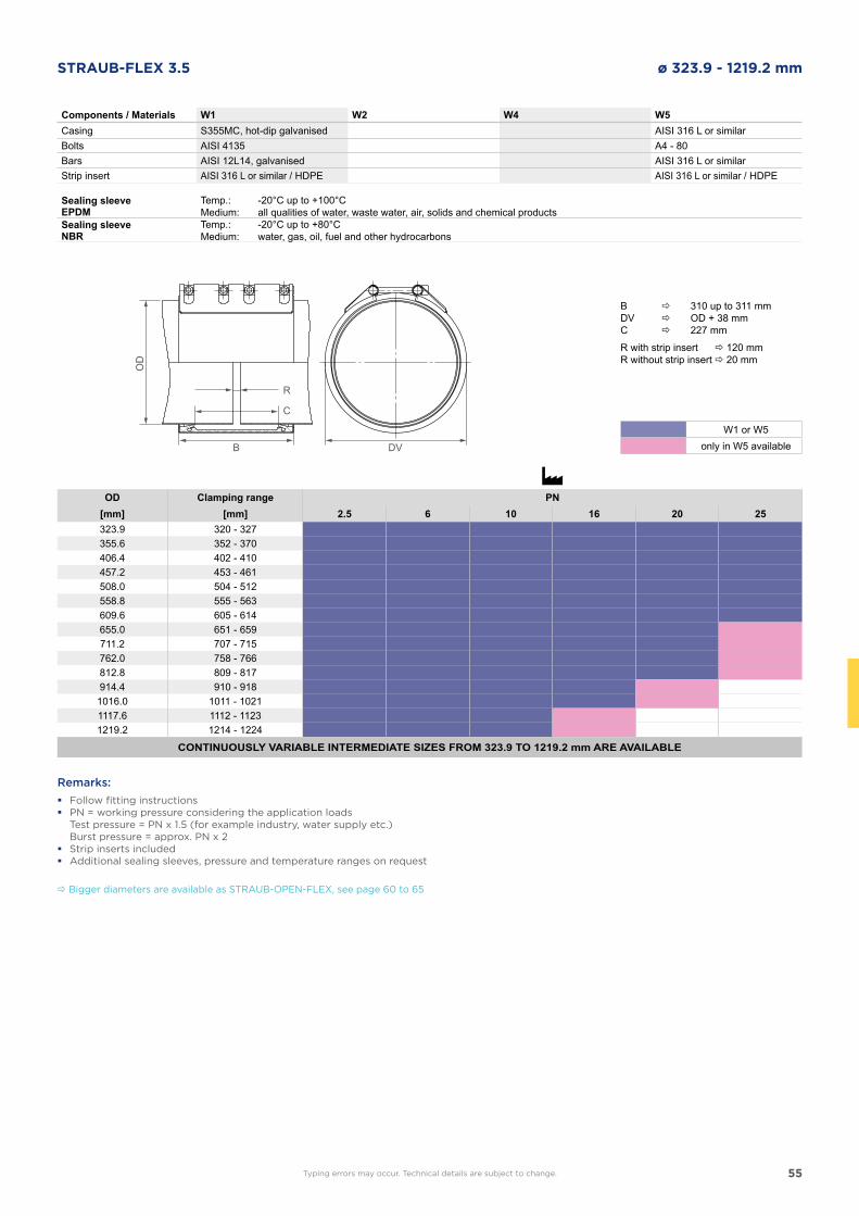
55
STRAUB-FLEX 3.5 ø 323.9 - 1219.2 mm
Components / Materials W1 W2 W4 W5Casing S355MC, hot-dip galvanised AISI 316 L or similarBolts AISI 4135 A4 - 80Bars AISI 12L14, galvanised AISI 316 L or similarStrip insert AISI 316 L or similar / HDPE AISI 316 L or similar / HDPE
Sealing sleeve EPDM
Temp.:Medium:
-20°C up to +100°Call qualities of water, waste water, air, solids and chemical products
Sealing sleeve NBR
Temp.:Medium:
-20°C up to +80°Cwater, gas, oil, fuel and other hydrocarbons
OD Clamping range PN[mm] [mm] 2.5 6 10 16 20 25323.9 320 - 327355.6 352 - 370406.4 402 - 410457.2 453 - 461508.0 504 - 512558.8 555 - 563609.6 605 - 614655.0 651 - 659711.2 707 - 715762.0 758 - 766812.8 809 - 817914.4 910 - 9181016.0 1011 - 10211117.6 1112 - 11231219.2 1214 - 1224
CONTINUOUSLY VARIABLE INTERMEDIATE SIZES FROM 323.9 TO 1219.2 mm ARE AVAILABLE
Remarks:
� Follow fitting instructions � PN = working pressure considering the application loads
Test pressure = PN x 1.5 (for example industry, water supply etc.) Burst pressure = approx. PN x 2 � Strip inserts included � Additional sealing sleeves, pressure and temperature ranges on request
DVB
OD
R
C
Typing errors may occur. Technical details are subject to change.
B 310 up to 311 mmDV OD + 38 mmC 227 mm
R with strip insert 120 mmR without strip insert 20 mm
W1 or W5only in W5 available
Bigger diameters are available as STRAUB-OPEN-FLEX, see page 60 to 65
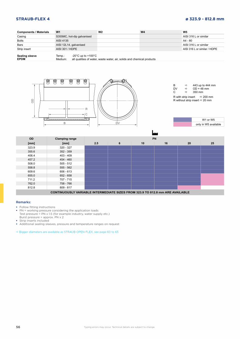
56
STRAUB-FLEX 4 ø 323.9 - 812.8 mm
Components / Materials W1 W2 W4 W5Casing S355MC, hot-dip galvanised AISI 316 L or similarBolts AISI 4135 A4 - 80Bars AISI 12L14, galvanised AISI 316 L or similarStrip insert AISI 301 / HDPE AISI 316 L or similar / HDPE
Sealing sleeve EPDM
Temp.:Medium:
-20°C up to +100°Call qualities of water, waste water, air, solids and chemical products
OD Clamping range PN[mm] [mm] 2.5 6 10 16 20 25323.9 320 - 327355.6 352 - 359406.4 403 - 409457.2 454 - 460508.0 505 - 512558.8 555 - 562609.6 606 - 613655.0 652 - 658711.2 707 - 715762.0 758 - 766812.8 809 - 817
CONTINUOUSLY VARIABLE INTERMEDIATE SIZES FROM 323.9 TO 812.8 mm ARE AVAILABLE
Remarks:
� Follow fitting instructions � PN = working pressure considering the application loads
Test pressure = PN x 1.5 (for example industry, water supply etc.) Burst pressure = approx. PN x 2 � Strip inserts included � Additional sealing sleeves, pressure and temperature ranges on request
DVB
OD
R
C
Typing errors may occur. Technical details are subject to change.
B 443 up to 444 mmDV OD + 48 mmC 350 mm
R with strip insert 200 mmR without strip insert 20 mm
W1 or W5only in W5 available
Bigger diameters are available as STRAUB-OPEN-FLEX, see page 60 to 65
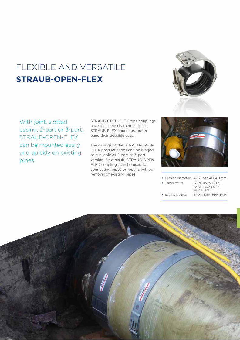
57
FLEXIBLE AND VERSATILE
STRAUB-OPEN-FLEX
STRAUB-OPEN-FLEX pipe couplings have the same characteristics as STRAUB-FLEX couplings, but ex-pand their possible uses.
The casings of the STRAUB-OPEN-FLEX product series can be hinged or available as 2-part or 3-part version. As a result, STRAUB-OPEN-FLEX couplings can be used for connecting pipes or repairs without removal of existing pipes.
With joint, slotted
casing, 2-part or 3-part,
STRAUB-OPEN-FLEX
can be mounted easily
and quickly on existing
pipes.
� Outside diameter: 48.3 up to 4064.0 mm
� Temperature: -20°C up to +180°C (OPEN-FLEX 3.5 + 4 up to +100°C)
� Sealing sleeve: EPDM, NBR, FPM/FKM
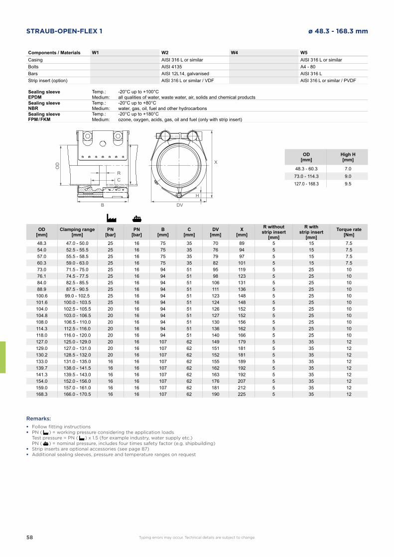
58
STRAUB-OPEN-FLEX 1 ø 48.3 - 168.3 mm
DVB
OD
RC
H
X
Components / Materials W1 W2 W4 W5Casing AISI 316 L or similar AISI 316 L or similarBolts AISI 4135 A4 - 80Bars AISI 12L14, galvanised AISI 316 LStrip insert (option) AISI 316 L or similar / VDF AISI 316 L or similar / PVDF
Sealing sleeve EPDM
Temp.:Medium:
-20°C up to +100°Call qualities of water, waste water, air, solids and chemical products
Sealing sleeve NBR
Temp.:Medium:
-20°C up to +80°Cwater, gas, oil, fuel and other hydrocarbons
Sealing sleeve FPM / FKM
Temp.:Medium:
-20°C up to +180°Cozone, oxygen, acids, gas, oil and fuel (only with strip insert)
OD[mm]
Clamping range[mm]
PN[bar]
PN[bar]
B[mm]
C[mm]
DV[mm]
X[mm]
R withoutstrip insert
[mm]
R withstrip insert
[mm]Torque rate
[Nm]
48.3 47.0 - 50.0 25 16 75 35 70 89 5 15 7.554.0 52.5 - 55.5 25 16 75 35 76 94 5 15 7.557.0 55.5 - 58.5 25 16 75 35 79 97 5 15 7.560.3 59.0 - 63.0 25 16 75 35 82 101 5 15 7.573.0 71.5 - 75.0 25 16 94 51 95 119 5 25 1076.1 74.5 - 77.5 25 16 94 51 98 123 5 25 1084.0 82.5 - 85.5 25 16 94 51 106 131 5 25 1088.9 87.5 - 90.5 25 16 94 51 111 136 5 25 10
100.6 99.0 - 102.5 25 16 94 51 123 148 5 25 10101.6 100.0 - 103.5 25 16 94 51 124 148 5 25 10104.0 102.5 - 105.5 20 16 94 51 126 152 5 25 10104.8 103.0 - 106.5 20 16 94 51 127 152 5 25 10108.0 106.5 - 110.0 20 16 94 51 130 156 5 25 10114.3 112.5 - 116.0 20 16 94 51 136 162 5 25 10118.0 116.0 - 120.0 20 16 94 51 140 166 5 25 10127.0 125.0 - 129.0 20 16 107 62 149 179 5 35 12129.0 127.0 - 131.0 20 16 107 62 151 181 5 35 12130.2 128.5 - 132.0 20 16 107 62 152 181 5 35 12133.0 131.0 - 135.0 16 16 107 62 155 189 5 35 12139.7 138.0 - 141.5 16 16 107 62 162 192 5 35 12141.3 139.5 - 143.0 16 16 107 62 163 192 5 35 12154.0 152.0 - 156.0 16 16 107 62 176 207 5 35 12159.0 157.0 - 161.0 16 16 107 62 181 212 5 35 12168.3 166.0 - 170.5 16 16 107 62 190 225 5 35 12
Remarks:
� Follow fitting instructions � PN ( ) = working pressure considering the application loads
Test pressure = PN ( ) x 1.5 (for example industry, water supply etc.) PN ( ) = nominal pressure, includes four times safety factor (e.g. shipbuilding) � Strip inserts are optional accessories (see page 87) � Additional sealing sleeves, pressure and temperature ranges on request
OD[mm]
High H[mm]
48.3 - 60.3 7.073.0 - 114.3 9.0127.0 - 168.3 9.5
Typing errors may occur. Technical details are subject to change.
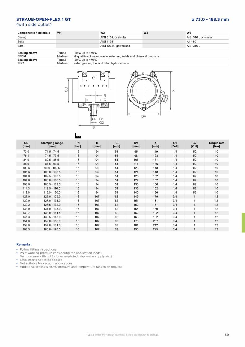
59
STRAUB-OPEN-FLEX 1 GT ø 73.0 - 168.3 mm
Components / Materials W1 W2 W4 W5Casing AISI 316 L or similar AISI 316 L or similarBolts AISI 4135 A4 - 80Bars AISI 12L14, galvanised AISI 316 L
Sealing sleeve EPDM
Temp.:Medium:
-20°C up to +70°Call qualities of water, waste water, air, solids and chemical products
Sealing sleeve NBR
Temp.:Medium:
-20°C up to +70°Cwater, gas, oil, fuel and other hydrocarbons
OD[mm]
Clamping range[mm]
PN[bar]
B[mm]
C[mm]
DV[mm]
X[mm]
G1[Zoll]
G2[Zoll]
Torque rate[Nm]
73.0 71.5 - 74.5 16 94 51 95 119 1/4 1/2 1076.1 74.5 - 77.5 16 94 51 98 123 1/4 1/2 1084.0 82.5 - 85.5 16 94 51 106 131 1/4 1/2 1088.9 87.5 - 90.5 16 94 51 111 136 1/4 1/2 10
100.6 99.0 - 102.5 16 94 51 123 148 1/4 1/2 10101.6 100.0 - 103.5 16 94 51 124 148 1/4 1/2 10104.0 102.5 - 105.5 16 94 51 126 152 1/4 1/2 10104.8 103.0 - 106.5 16 94 51 127 152 1/4 1/2 10108.0 106.5 - 109.5 16 94 51 130 156 1/4 1/2 10114.3 112.5 - 116.0 16 94 51 136 162 1/4 1/2 10118.0 116.0 - 120.0 16 94 51 140 166 1/4 1/2 10127.0 125.0 - 129.0 16 107 62 149 179 3/4 1 12129.0 127.0 - 131.0 16 107 62 151 181 3/4 1 12130.2 128.5 - 132.0 16 107 62 152 181 3/4 1 12133.0 131.0 - 135.0 16 107 62 155 189 3/4 1 12139.7 138.0 - 141.5 16 107 62 162 192 3/4 1 12141.3 139.5 - 143.0 16 107 62 163 192 3/4 1 12154.0 152.0 - 156.0 16 107 62 176 207 3/4 1 12159.0 157.0 - 161.0 16 107 62 181 212 3/4 1 12168.3 166.0 - 170.5 16 107 62 190 225 3/4 1 12
Remarks:
� Follow fitting instructions � PN = working pressure considering the application loads
Test pressure = PN x 1.5 (for example industry, water supply etc.) � Strip inserts not to be applied � Not suitable for vacuum applications � Additional sealing sleeves, pressure and temperature ranges on request
DV
B
RC
G2G1
OD X
(with side outlet)
Typing errors may occur. Technical details are subject to change.
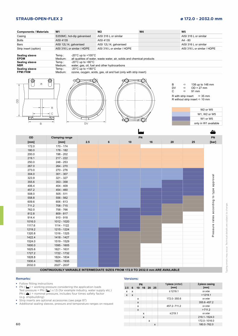
60
STRAUB-OPEN-FLEX 2 ø 172.0 - 2032.0 mm
Components / Materials W1 W2 W4 W5Casing S355MC, hot-dip galvanised AISI 316 L or similar AISI 316 L or similarBolts AISI 4135 AISI 4135 A4 - 80Bars AISI 12L14, galvanised AISI 12L14, galvanised AISI 316 L or similarStrip insert (option) AISI 316 L or similar / HDPE AISI 316 L or similar / HDPE AISI 316 L or similar / HDPE
Sealing sleeve EPDM
Temp.:Medium:
-20°C up to +100°Call qualities of water, waste water, air, solids and chemical products
Sealing sleeve NBR
Temp.:Medium:
-20°C up to +80°Cwater, gas, oil, fuel and other hydrocarbons
Sealing sleeve FPM / FKM
Temp.:Medium:
-20°C up to +180°Cozone, oxygen, acids, gas, oil and fuel (only with strip insert)
Remarks:
� Follow fitting instructions � PN ( ) = working pressure considering the application loads
Test pressure = PN ( ) x 1.5 (for example industry, water supply etc.) PN ( ) = nominal pressure, includes four times safety factor
(e.g. shipbuilding) � Strip inserts are optional accessories (see page 87) � Additional sealing sleeves, pressure and temperature ranges on request
DVB
OD
R
C
Typ
ing
err
ors
may o
ccu
r. T
ech
nic
al d
eta
ils a
re s
ub
ject
to c
han
ge.
OD Clamping range PN PN[mm] [mm] 2.5 6 10 16 20 25 [bar]172.0 170 - 174
Pre
ssur
e ra
tes
acco
rdin
g to
typ
e ap
prov
al
180.0 178 - 182200.0 198 - 202219.1 217 - 222250.0 248 - 253267.0 264 - 270273.0 270 - 276304.0 301 - 307323.9 321 - 327355.6 353 - 358406.4 404 - 409457.2 454 - 460508.0 505 - 511558.8 556 - 562609.6 606 - 613711.2 708 - 715762.0 758 - 766812.8 809 - 817914.4 910 - 9181016.0 1012 - 10201117.6 1114 - 11221219.2 1215 - 12241320.8 1316 - 13251422.4 1418 - 14271524.0 1519 - 15291600.0 1595 - 16051625.6 1621 - 16311727.2 1722 - 17321828.8 1824 - 18341930.4 1925 - 19352032.0 2027 - 2037
CONTINUOUSLY VARIABLE INTERMEDIATE SIZES FROM 172.0 TO 2032.0 mm ARE AVAILABLE
B 138 up to 148 mmDV OD + 27 mmC 91 mm
R with strip insert 35 mmR without strip insert 10 mm
W2 or W5W1, W2 or W5
W1 or W5only in W1 available
PN 1 piece (slotted) 2 piece casing2.5 6 10 16 20 25 [mm] [mm]x x ≤ 1219.1 on orderx x > 1219.1
x 172.0 - 355.6 on orderx 355.6 - 457.2x 457.2 - 711.2 on orderx > 711.2
x ≤ 219.1 on orderx 219.1 - 1524.0
x 172.0 - 1016.0x 180.0 - 762.0
Versions:
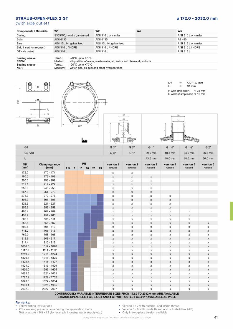
61
STRAUB-OPEN-FLEX 2 GT ø 172.0 - 2032.0 mm
Components / Materials W1 W2 W4 W5Casing S355MC, hot-dip galvanised AISI 316 L or similar AISI 316 L or similarBolts AISI 4135 AISI 4135 A4 - 80Bars AISI 12L 14, galvanised AISI 12L 14, galvanised AISI 316 L or similarStrip insert (on request) AISI 316 L / HDPE AISI 316 L / HDPE AISI 316 L / HDPEGT side outlet AISI 316 L AISI 316 L AISI 316 L
Sealing sleeve EPDM
Temp.:Medium:
-20°C up to +70°Call qualities of water, waste water, air, solids and chemical products
Sealing sleeve NBR
Temp.:Medium:
-20°C up to +70°Cwater, gas, oil, fuel and other hydrocarbons
(with side outlet)
B
OD
RC
DV
G2
G1
L
AB
G1
L
G1 G ¼″ G ¾″ G 1″ G 1¼″ G 1½″ G 2″
G2 / AB G ½″ G 1″ 39.5 mm 48.3 mm 54.5 mm 66.3 mm
L 43.0 mm 48.0 mm 48.0 mm 56.0 mm
OD[mm]
Clamping range[mm]
PN version 1screwed
version 2screwed
version 3welded
version 4welded
version 5welded
version 6welded2.5 6 10 16 20 25
172.0 170 - 174 x x180.0 178 - 182 x x x200.0 198 - 202 x x x219.1 217 - 222 x x x250.0 248 - 253 x x x267.0 264 - 270 x x x273.0 270 - 276 x x x x304.0 301 - 307 x x x x323.9 321 - 327 x x x x355.6 353 - 358 x x x x406.4 404 - 409 x x x x x457.2 454 - 460 x x x x x508.0 505 - 511 x x x x x558.8 556 - 562 x x x x x x609.6 606 - 613 x x x x x x711.2 708 - 715 x x x x x x762.0 758 - 766 x x x x x x812.8 809 - 817 x x x x x x914.4 910 - 918 x x x x x x1016.0 1012 - 1020 x x x x x x1117.6 1114 - 1122 x x x x x x1219.2 1215 - 1224 x x x x x x1320.8 1316 - 1325 x x x x x x1422.4 1418 - 1427 x x x x x x1524.0 1519 - 1529 x x x x x x1600.0 1595 - 1605 x x x x x x1625.6 1621 - 1631 x x x x x x1727.2 1722 - 1732 x x x x x x1828.8 1824 - 1834 x x x x x x1930.4 1925 - 1935 x x x x x x2032.0 2027 - 2037 x x x x x x
CONTINUOUSLY VARIABLE INTERMEDIATE SIZES FROM 172.0 TO 2032.0 mm ARE AVAILABLESTRAUB-OPEN-FLEX 3 GT, 3.5 GT AND 4 GT WITH OUTLET G3/4”/1” AVAILABLE AS WELL
Remarks: � Follow fitting instructions � PN = working pressure considering the application loads
Test pressure = PN x 1.5 (for example industry, water supply etc.)
DV OD + 27 mmC 91 mm
R with strip insert 35 mmR without strip insert 10 mm
Typing errors may occur. Technical details are subject to change.
� Version 1 + 2 with outside- and inside thread � Version 3 - 6 with inside thread and outside blank (AB) � Only in two-piece version available
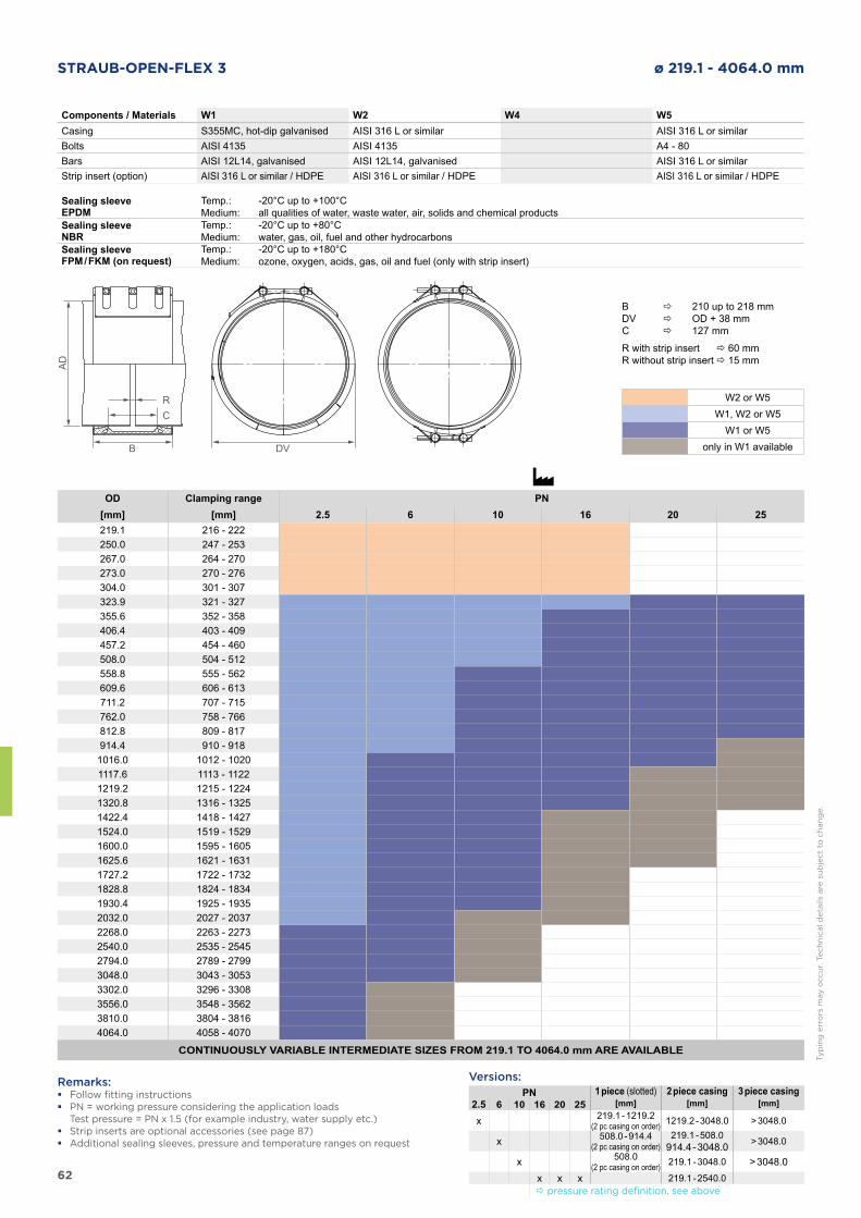
62
STRAUB-OPEN-FLEX 3 ø 219.1 - 4064.0 mm
Components / Materials W1 W2 W4 W5Casing S355MC, hot-dip galvanised AISI 316 L or similar AISI 316 L or similarBolts AISI 4135 AISI 4135 A4 - 80Bars AISI 12L14, galvanised AISI 12L14, galvanised AISI 316 L or similarStrip insert (option) AISI 316 L or similar / HDPE AISI 316 L or similar / HDPE AISI 316 L or similar / HDPE
Sealing sleeve EPDM
Temp.:Medium:
-20°C up to +100°Call qualities of water, waste water, air, solids and chemical products
Sealing sleeve NBR
Temp.:Medium:
-20°C up to +80°Cwater, gas, oil, fuel and other hydrocarbons
Sealing sleeve FPM / FKM (on request)
Temp.:Medium:
-20°C up to +180°Cozone, oxygen, acids, gas, oil and fuel (only with strip insert)
Remarks: � Follow fitting instructions � PN = working pressure considering the application loads
Test pressure = PN x 1.5 (for example industry, water supply etc.) � Strip inserts are optional accessories (see page 87) � Additional sealing sleeves, pressure and temperature ranges on request
DVB
AD
RC
Typ
ing
err
ors
may o
ccu
r. T
ech
nic
al d
eta
ils a
re s
ub
ject
to c
han
ge.
OD Clamping range PN[mm] [mm] 2.5 6 10 16 20 25219.1 216 - 222250.0 247 - 253267.0 264 - 270273.0 270 - 276304.0 301 - 307323.9 321 - 327355.6 352 - 358406.4 403 - 409457.2 454 - 460508.0 504 - 512558.8 555 - 562609.6 606 - 613711.2 707 - 715762.0 758 - 766812.8 809 - 817914.4 910 - 9181016.0 1012 - 10201117.6 1113 - 11221219.2 1215 - 12241320.8 1316 - 13251422.4 1418 - 14271524.0 1519 - 15291600.0 1595 - 16051625.6 1621 - 16311727.2 1722 - 17321828.8 1824 - 18341930.4 1925 - 19352032.0 2027 - 20372268.0 2263 - 22732540.0 2535 - 25452794.0 2789 - 27993048.0 3043 - 30533302.0 3296 - 33083556.0 3548 - 35623810.0 3804 - 38164064.0 4058 - 4070
CONTINUOUSLY VARIABLE INTERMEDIATE SIZES FROM 219.1 TO 4064.0 mm ARE AVAILABLE
B 210 up to 218 mmDV OD + 38 mmC 127 mm
R with strip insert 60 mmR without strip insert 15 mm
W2 or W5W1, W2 or W5
W1 or W5only in W1 available
Versions:PN 1 piece (slotted) 2 piece casing 3 piece casing
2.5 6 10 16 20 25 [mm] [mm] [mm]
x 219.1 - 1219.2(2 pc casing on order) 1219.2 - 3048.0 > 3048.0
x 508.0 - 914.4(2 pc casing on order)
219.1 - 508.0914.4 - 3048.0 > 3048.0
x 508.0(2 pc casing on order) 219.1 - 3048.0 > 3048.0
x x x 219.1 - 2540.0 pressure rating definition, see above
63
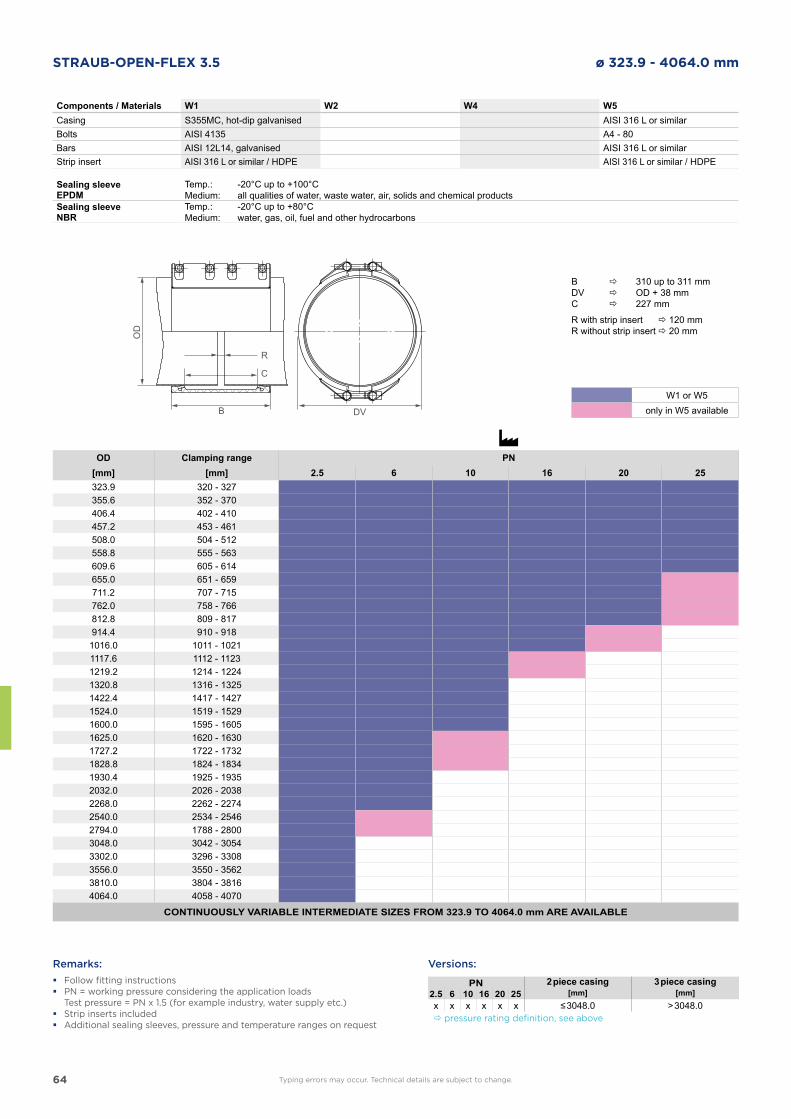
64
STRAUB-OPEN-FLEX 3.5 ø 323.9 - 4064.0 mm
Components / Materials W1 W2 W4 W5Casing S355MC, hot-dip galvanised AISI 316 L or similarBolts AISI 4135 A4 - 80Bars AISI 12L14, galvanised AISI 316 L or similarStrip insert AISI 316 L or similar / HDPE AISI 316 L or similar / HDPE
Sealing sleeve EPDM
Temp.:Medium:
-20°C up to +100°Call qualities of water, waste water, air, solids and chemical products
Sealing sleeve NBR
Temp.:Medium:
-20°C up to +80°Cwater, gas, oil, fuel and other hydrocarbons
OD Clamping range PN[mm] [mm] 2.5 6 10 16 20 25323.9 320 - 327355.6 352 - 370406.4 402 - 410457.2 453 - 461508.0 504 - 512558.8 555 - 563609.6 605 - 614655.0 651 - 659711.2 707 - 715762.0 758 - 766812.8 809 - 817914.4 910 - 9181016.0 1011 - 10211117.6 1112 - 11231219.2 1214 - 12241320.8 1316 - 13251422.4 1417 - 14271524.0 1519 - 15291600.0 1595 - 16051625.0 1620 - 16301727.2 1722 - 17321828.8 1824 - 18341930.4 1925 - 19352032.0 2026 - 20382268.0 2262 - 22742540.0 2534 - 25462794.0 1788 - 28003048.0 3042 - 30543302.0 3296 - 33083556.0 3550 - 35623810.0 3804 - 38164064.0 4058 - 4070
CONTINUOUSLY VARIABLE INTERMEDIATE SIZES FROM 323.9 TO 4064.0 mm ARE AVAILABLE
Remarks:
� Follow fitting instructions � PN = working pressure considering the application loads
Test pressure = PN x 1.5 (for example industry, water supply etc.) � Strip inserts included � Additional sealing sleeves, pressure and temperature ranges on request
DVB
OD
R
C
Typing errors may occur. Technical details are subject to change.
B 310 up to 311 mmDV OD + 38 mmC 227 mm
R with strip insert 120 mmR without strip insert 20 mm
Versions:
PN 2 piece casing 3 piece casing2.5 6 10 16 20 25 [mm] [mm]x x x x x x ≤ 3048.0 > 3048.0 pressure rating definition, see above
W1 or W5only in W5 available
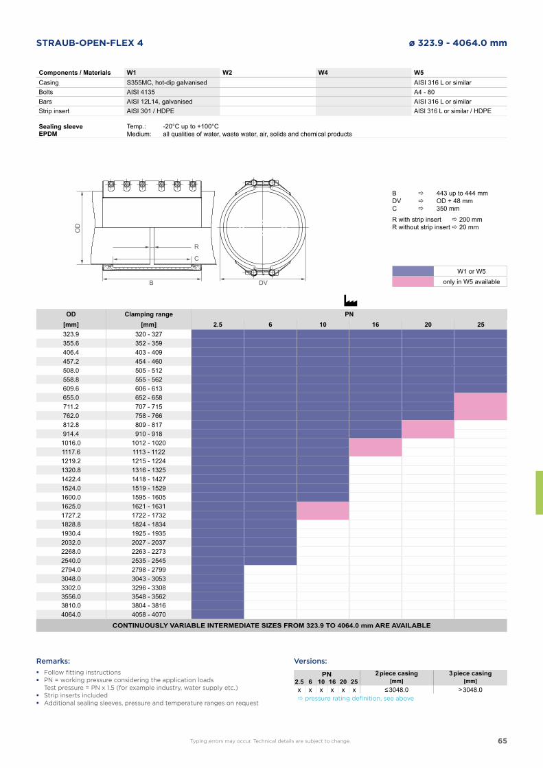
65
STRAUB-OPEN-FLEX 4 ø 323.9 - 4064.0 mm
Components / Materials W1 W2 W4 W5Casing S355MC, hot-dip galvanised AISI 316 L or similarBolts AISI 4135 A4 - 80Bars AISI 12L14, galvanised AISI 316 L or similarStrip insert AISI 301 / HDPE AISI 316 L or similar / HDPE
Sealing sleeve EPDM
Temp.:Medium:
-20°C up to +100°Call qualities of water, waste water, air, solids and chemical products
OD Clamping range PN[mm] [mm] 2.5 6 10 16 20 25323.9 320 - 327355.6 352 - 359406.4 403 - 409457.2 454 - 460508.0 505 - 512558.8 555 - 562609.6 606 - 613655.0 652 - 658711.2 707 - 715762.0 758 - 766812.8 809 - 817914.4 910 - 9181016.0 1012 - 10201117.6 1113 - 11221219.2 1215 - 12241320.8 1316 - 13251422.4 1418 - 14271524.0 1519 - 15291600.0 1595 - 16051625.0 1621 - 16311727.2 1722 - 17321828.8 1824 - 18341930.4 1925 - 19352032.0 2027 - 20372268.0 2263 - 22732540.0 2535 - 25452794.0 2798 - 27993048.0 3043 - 30533302.0 3296 - 33083556.0 3548 - 35623810.0 3804 - 38164064.0 4058 - 4070
CONTINUOUSLY VARIABLE INTERMEDIATE SIZES FROM 323.9 TO 4064.0 mm ARE AVAILABLE
Remarks:
� Follow fitting instructions � PN = working pressure considering the application loads
Test pressure = PN x 1.5 (for example industry, water supply etc.) � Strip inserts included � Additional sealing sleeves, pressure and temperature ranges on request
DVB
OD
R
C
Typing errors may occur. Technical details are subject to change.
B 443 up to 444 mmDV OD + 48 mmC 350 mm
R with strip insert 200 mmR without strip insert 20 mm
Versions:
PN 2 piece casing 3 piece casing2.5 6 10 16 20 25 [mm] [mm]x x x x x x ≤ 3048.0 > 3048.0 pressure rating definition, see above
W1 or W5only in W5 available

66
DNV GL FIRE PROVED STRAUB COUPLING
STRAUB-OPEN-FLEX FIRE-FENCE
Fire-endurance test in accordance with ISO 19921 and 19922
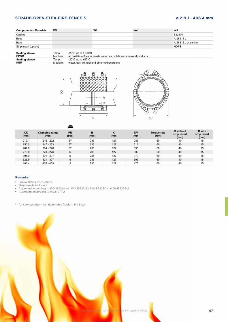
67
STRAUB-OPEN-FLEX-FIRE-FENCE 3 ø 219.1 - 406.4 mm
Components / Materials W1 W2 W4 W5Casing S32101Bolts AISI 316 LBars AISI 316 L or similarStrip insert (option) HDPE
Remarks:
� Follow fitting instructions � Strip inserts included � Approved according to ISO 19921-1 and ISO 19922-2 / DIN 86228-1 and DIN86228-2 � Approved according to IACS URP2
DVB
OD
R
C
OD[mm]
Clamping range[mm]
PN[bar]
B[mm]
C[mm]
DV[mm]
Torque rate[Nm]
R withoutstrip insert
[mm]
R with strip insert
[mm]219.1 216 - 222 511 235 127 285 60 40 15250.0 247 - 253 511 235 127 316 60 40 15267.0 264 - 270 511 235 127 333 60 40 15273.0 270 - 276 6 235 127 339 60 40 15304.0 301 - 307 5 235 127 370 60 40 15323.9 321 - 327 5 235 127 393 60 40 15406.4 403 - 409 5 235 127 475 60 40 15
11 for service other than flammable fluids PN 6 bar
Sealing sleeve EPDM
Temp.:Medium:
-20°C up to +100°Call qualities of water, waste water, air, solids and chemical products
Sealing sleeve NBR
Temp.:Medium:
-20°C up to +80°Cwater, gas, oil, fuel and other hydrocarbons
Typing errors may occur. Technical details are subject to change.
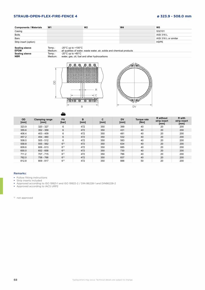
68
STRAUB-OPEN-FLEX-FIRE-FENCE 4 ø 323.9 - 508.0 mm
Components / Materials W1 W2 W4 W5Casing S32101Bolts AISI 316 LBars AISI 316 L or similarStrip insert (option) HDPE
Remarks:
� Follow fitting instructions � Strip inserts included � Approved according to ISO 19921-1 and ISO 19922-2 / DIN 86228-1 and DIN86228-2 � Approved according to IACS URP2
DVB
OD
R
C
Sealing sleeve EPDM
Temp.:Medium:
-20°C up to +100°Call qualities of water, waste water, air, solids and chemical products
Sealing sleeve NBR
Temp.:Medium:
-20°C up to +80°Cwater, gas, oil, fuel and other hydrocarbons
OD[mm]
Clamping range[mm]
PN[bar]
B[mm]
C[mm]
DV[mm]
Torque rate[Nm]
R withoutstrip insert
[mm]
R with strip insert
[mm]323.9 320 - 327 6 472 350 399 40 20 200355.6 352 - 359 6 472 350 431 40 20 200406.4 403 - 409 6 472 350 481 40 20 200457.2 454 - 460 6 472 350 532 40 20 200508.0 505 - 512 6 472 350 583 40 20 200558.8 555 - 562 612 472 350 634 40 20 200609.6 606 - 613 612 472 350 685 40 20 200655.0 652 - 658 612 472 350 730 40 20 200711.2 707 - 715 612 472 350 786 40 20 200762.0 758 - 766 612 472 350 837 40 20 200812.8 809 - 817 612 472 350 888 50 20 200
12 not approved
Typing errors may occur. Technical details are subject to change.
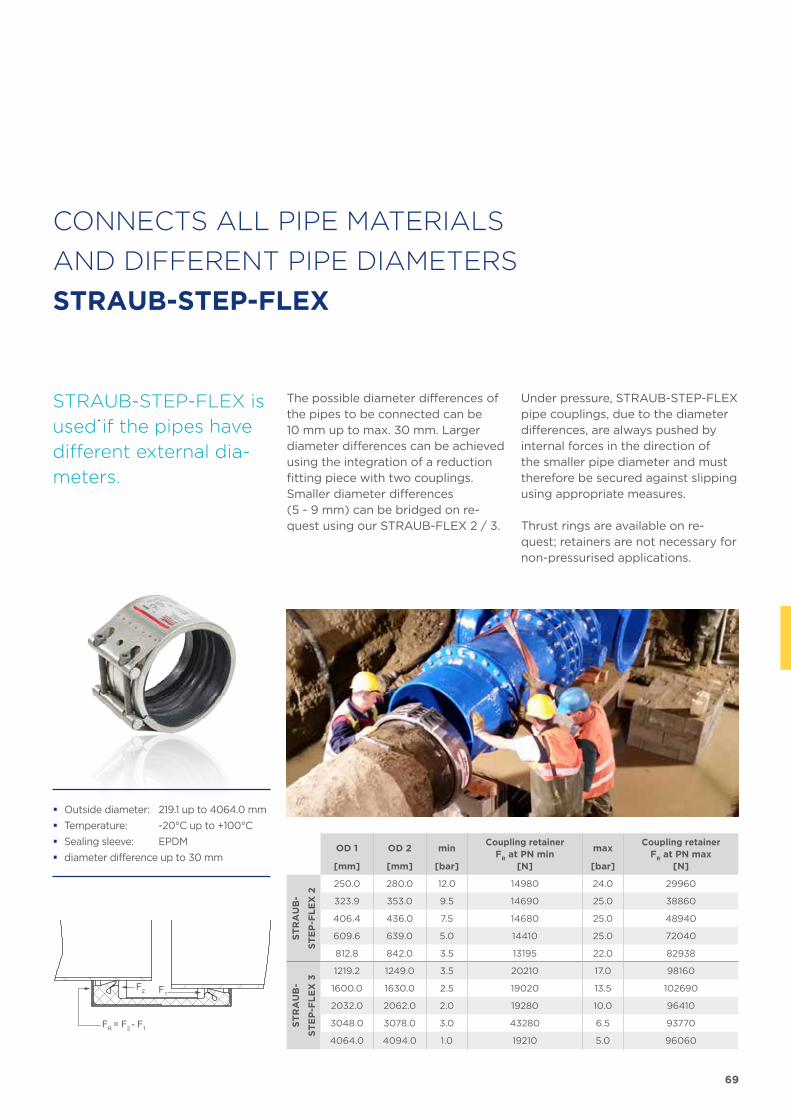
69
FR = F2 - F1
F2 F1
CONNECTS ALL PIPE MATERIALS
AND DIFFERENT PIPE DIAMETERS
STRAUB-STEP-FLEX
STRAUB-STEP-FLEX is
used if the pipes have
different external dia-
meters.
The possible diameter differences of the pipes to be connected can be 10 mm up to max. 30 mm. Larger dia meter differences can be achieved using the integration of a reduction fitting piece with two couplings. Smaller diameter differences (5 - 9 mm) can be bridged on re-quest using our STRAUB-FLEX 2 / 3.
Under pressure, STRAUB-STEP-FLEX pipe couplings, due to the diameter differences, are always pushed by internal forces in the direction of the smaller pipe dia meter and must therefore be secured against slipping using appropriate measures.
Thrust rings are available on re-quest; retainers are not necessary for non-pressurised applications.
� Outside diameter: 219.1 up to 4064.0 mm
� Temperature: -20°C up to +100°C
� Sealing sleeve: EPDM
� diameter difference up to 30 mmOD 1 OD 2 min
Coupling retainerF
R at PN min
maxCoupling retainer
FR at PN max
[mm] [mm] [bar] [N] [bar] [N]
ST
RA
UB
-
ST
EP
-FL
EX
2
250.0 280.0 12.0 14980 24.0 29960
323.9 353.0 9.5 14690 25.0 38860
406.4 436.0 7.5 14680 25.0 48940
609.6 639.0 5.0 14410 25.0 72040
812.8 842.0 3.5 13195 22.0 82938
ST
RA
UB
-
ST
EP
-FL
EX
3
1219.2 1249.0 3.5 20210 17.0 98160
1600.0 1630.0 2.5 19020 13.5 102690
2032.0 2062.0 2.0 19280 10.0 96410
3048.0 3078.0 3.0 43280 6.5 93770
4064.0 4094.0 1.0 19210 5.0 96060
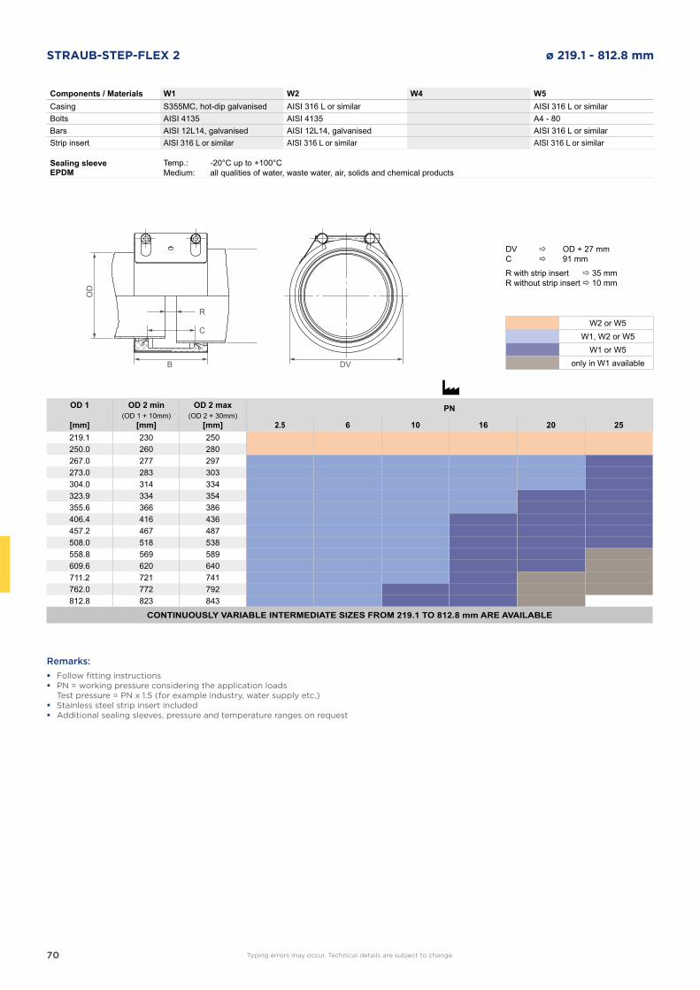
70
STRAUB-STEP-FLEX 2 ø 219.1 - 812.8 mm
Components / Materials W1 W2 W4 W5Casing S355MC, hot-dip galvanised AISI 316 L or similar AISI 316 L or similarBolts AISI 4135 AISI 4135 A4 - 80Bars AISI 12L14, galvanised AISI 12L14, galvanised AISI 316 L or similarStrip insert AISI 316 L or similar AISI 316 L or similar AISI 316 L or similar
Sealing sleeve EPDM
Temp.:Medium:
-20°C up to +100°Call qualities of water, waste water, air, solids and chemical products
OD 1 OD 2 min OD 2 max PN(OD 1 + 10mm) (OD 2 + 30mm)
[mm] [mm] [mm] 2.5 6 10 16 20 25219.1 230 250250.0 260 280267.0 277 297273.0 283 303304.0 314 334323.9 334 354355.6 366 386406.4 416 436457.2 467 487508.0 518 538558.8 569 589609.6 620 640711.2 721 741762.0 772 792812.8 823 843
CONTINUOUSLY VARIABLE INTERMEDIATE SIZES FROM 219.1 TO 812.8 mm ARE AVAILABLE
Remarks:
� Follow fitting instructions � PN = working pressure considering the application loads
Test pressure = PN x 1.5 (for example industry, water supply etc.) � Stainless steel strip insert included � Additional sealing sleeves, pressure and temperature ranges on request
DVB
OD
R
C
Typing errors may occur. Technical details are subject to change.
DV OD + 27 mmC 91 mm
R with strip insert 35 mmR without strip insert 10 mm
W2 or W5W1, W2 or W5
W1 or W5only in W1 available
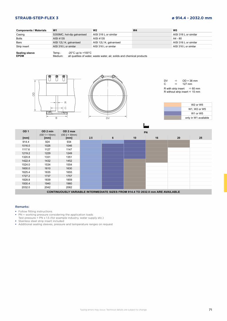
71
STRAUB-STEP-FLEX 3 ø 914.4 - 2032.0 mm
Components / Materials W1 W2 W4 W5Casing S355MC, hot-dip galvanised AISI 316 L or simiIar AISI 316 L or similarBolts AISI 4135 AISI 4135 A4 - 80Bars AISI 12L14, galvanised AISI 12L14, galvanised AISI 316 L or similarStrip insert AISI 316 L or similar AISI 316 L or similar AISI 316 L or similar
Sealing sleeve EPDM
Temp.:Medium:
-20°C up to +100°Call qualities of water, waste water, air, solids and chemical products
OD 1 OD 2 min OD 2 max PN(OD 1 + 10mm) (OD 2 + 30mm)
[mm] [mm] [mm] 2.5 6 10 16 20 25914.4 924 934
1016.0 1026 10461117.6 1127 11471219.2 1229 12491320.8 1331 13511422.4 1432 14521524.0 1534 15541600.0 1610 16301625.4 1635 16551727.2 1737 17571828.8 1839 18591930.4 1940 19602032.0 2042 2062
CONTINUOUSLY VARIABLE INTERMEDIATE SIZES FROM 914.4 TO 2032.0 mm ARE AVAILABLE
Remarks:
� Follow fitting instructions � PN = working pressure considering the application loads
Test pressure = PN x 1.5 (for example industry, water supply etc.) � Stainless steel strip insert included � Additional sealing sleeves, pressure and temperature ranges on request
DVB
OD
R
C
Typing errors may occur. Technical details are subject to change.
DV OD + 38 mmC 127 mm
R with strip insert 60 mmR without strip insert 15 mm
W2 or W5W1, W2 or W5
W1 or W5only in W1 available
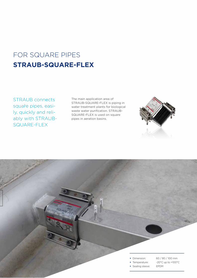
72
� Dimension: 60 / 80 / 100 mm
� Temperature: -20°C up to +100°C
� Sealing sleeve: EPDM
STRAUB connects
square pipes, easi-
ly, quickly and reli-
ably with STRAUB-
SQUARE-FLEX
The main application area of STRAUB-SQUARE-FLEX is piping in water treatment plants for biological waste water purification. STRAUB-SQUARE-FLEX is used on square pipes in aeration basins.
FOR SQUARE PIPES
STRAUB-SQUARE-FLEX
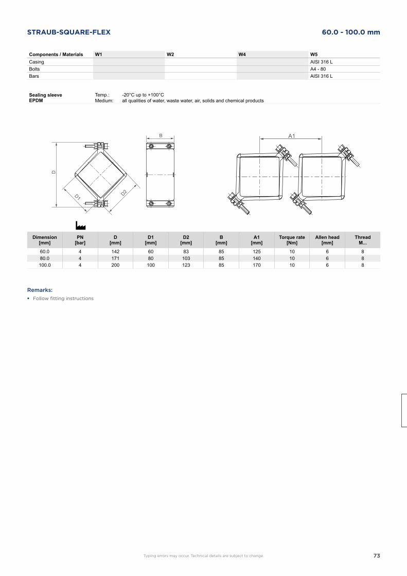
73
STRAUB-SQUARE-FLEX 60.0 - 100.0 mm
B
D
A1
Components / Materials W1 W2 W4 W5Casing AISI 316 LBolts A4 - 80Bars AISI 316 L
Sealing sleeve EPDM
Temp.:Medium:
-20°C up to +100°Call qualities of water, waste water, air, solids and chemical products
Dimension[mm]
PN[bar]
D[mm]
D1[mm]
D2[mm]
B[mm]
A1[mm]
Torque rate[Nm]
Allen head[mm]
ThreadM...
60.0 4 142 60 83 85 125 10 6 880.0 4 171 80 103 85 140 10 6 8100.0 4 200 100 123 85 170 10 6 8
Remarks:
� Follow fitting instructions
Typing errors may occur. Technical details are subject to change.
74
STRAUB
REPAIR PRODUCTS
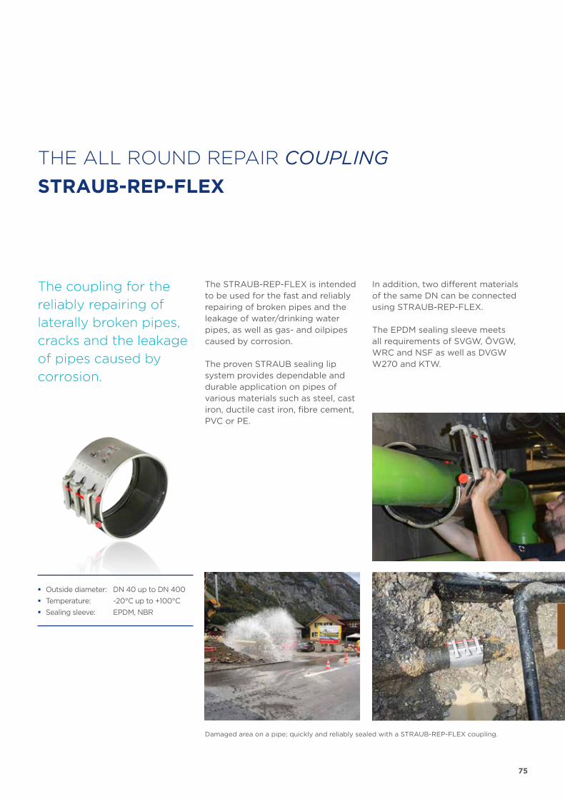
75
The coupling for the
reliably repairing of
lateral ly broken pipes,
cracks and the leakage
of pipes caused by
corrosion.
The STRAUB-REP-FLEX is intended to be used for the fast and reliably repairing of broken pipes and the leakage of water/drinking water pipes, as well as gas- and oilpipes caused by corrosion.
The proven STRAUB sealing lip system provides dependable and durable application on pipes of various materials such as steel, cast iron, ductile cast iron, fibre cement, PVC or PE.
In addition, two different materials of the same DN can be connected using STRAUB-REP-FLEX.
The EPDM sealing sleeve meets all requirements of SVGW, ÖVGW, WRC and NSF as well as DVGW W270 and KTW.
� Outside diameter: DN 40 up to DN 400
� Temperature: -20°C up to +100°C
� Sealing sleeve: EPDM, NBR
THE ALL ROUND REPAIR COUPLING
STRAUB-REP-FLEX
Damaged area on a pipe; quickly and reliably sealed with a STRAUB-REP-FLEX coupling.
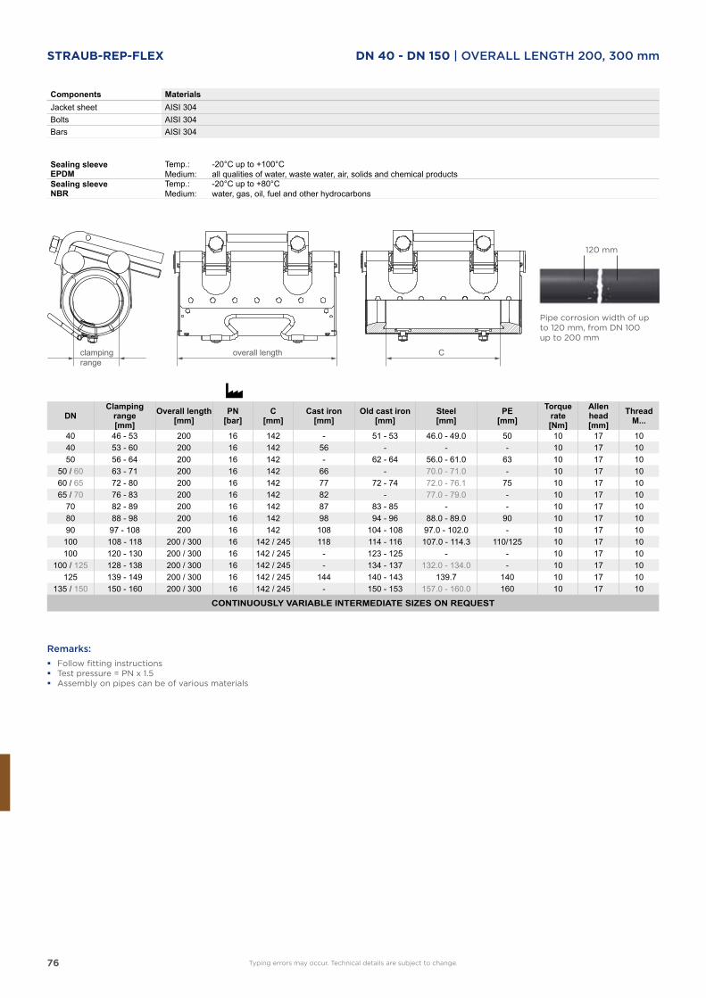
76
Components MaterialsJacket sheet AISI 304Bolts AISI 304Bars AISI 304
Sealing sleeve EPDM
Temp.:Medium:
-20°C up to +100°Call qualities of water, waste water, air, solids and chemical products
Sealing sleeve NBR
Temp.:Medium:
-20°C up to +80°Cwater, gas, oil, fuel and other hydrocarbons
DNClamping
range[mm]
Overall length[mm]
PN[bar]
C[mm]
Cast iron[mm]
Old cast iron[mm]
Steel[mm]
PE[mm]
Torque rate[Nm]
Allen head[mm]
ThreadM...
40 46 - 53 200 16 142 - 51 - 53 46.0 - 49.0 50 10 17 1040 53 - 60 200 16 142 56 - - - 10 17 1050 56 - 64 200 16 142 - 62 - 64 56.0 - 61.0 63 10 17 10
50 / 60 63 - 71 200 16 142 66 - 70.0 - 71.0 - 10 17 1060 / 65 72 - 80 200 16 142 77 72 - 74 72.0 - 76.1 75 10 17 1065 / 70 76 - 83 200 16 142 82 - 77.0 - 79.0 - 10 17 10
70 82 - 89 200 16 142 87 83 - 85 - - 10 17 1080 88 - 98 200 16 142 98 94 - 96 88.0 - 89.0 90 10 17 1090 97 - 108 200 16 142 108 104 - 108 97.0 - 102.0 - 10 17 10
100 108 - 118 200 / 300 16 142 / 245 118 114 - 116 107.0 - 114.3 110/125 10 17 10100 120 - 130 200 / 300 16 142 / 245 - 123 - 125 - - 10 17 10
100 / 125 128 - 138 200 / 300 16 142 / 245 - 134 - 137 132.0 - 134.0 - 10 17 10125 139 - 149 200 / 300 16 142 / 245 144 140 - 143 139.7 140 10 17 10
135 / 150 150 - 160 200 / 300 16 142 / 245 - 150 - 153 157.0 - 160.0 160 10 17 10
CONTINUOUSLY VARIABLE INTERMEDIATE SIZES ON REQUEST
120 mm
Pipe corrosion width of upto 120 mm, from DN 100up to 200 mm
Remarks:
� Follow fitting instructions � Test pressure = PN x 1.5 � Assembly on pipes can be of various materials
clamping range
overall length C
Typing errors may occur. Technical details are subject to change.
STRAUB-REP-FLEX DN 40 - DN 150 | OVERALL LENGTH 200, 300 mm
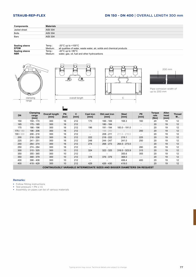
77
Components MaterialsJacket sheet AISI 304Bolts AISI 304Bars AISI 304
Sealing sleeve EPDM
Temp.:Medium:
-20°C up to +100°Call qualities of water, waste water, air, solids and chemical products
Sealing sleeve NBR
Temp.:Medium:
-20°C up to +80°Cwater, gas, oil, fuel and other hydrocarbons
DNClamping
range[mm]
Overall length[mm]
PN[bar]
C[mm]
Cast iron[mm]
Old cast iron[mm]
Steel[mm]
PE[mm]
Torque rate[Nm]
Allen head[mm]
ThreadM...
150 159 - 170 300 16 212 170 166 - 169 168.3 160 20 19 12165 175 - 185 300 16 212 - 180 - 184 - - 20 19 12175 186 - 196 300 16 212 196 191 - 194 183.0 - 191.0 - 20 19 12
175 / 180 196 - 206 300 16 212 - 198 - 200 - 200 20 19 12190 / 200 206 - 216 300 16 212 - 208 - 211 211.0 - 216.0 - 20 19 12
200 216 - 226 300 16 212 222 218 - 222 219.1 225 20 19 12225 241 - 251 300 16 212 248 244 - 247 241.0 250 20 19 12250 264 - 274 300 16 212 274 268 - 273 264.0 - 273.0 - 20 19 12250 274 - 284 300 16 212 - - - 280 20 19 12300 315 - 325 300 10 212 324 322 - 325 316.0 - 323.9 315 20 19 12350 355 - 365 300 10 212 - - 355.6 355 20 19 12350 368 - 379 300 10 212 378 376 - 379 368.0 - 20 19 12400 398 - 408 300 10 212 - - 406.4 400 20 19 12400 419 - 429 300 10 212 429 426 - 430 419.0 - 20 19 12
CONTINUOUSLY VARIABLE INTERMEDIATE SIZES AND BIGGER DIAMETERS ON REQUEST
Pipe corrosion width ofup to 200 mm
200 mm
Remarks:
� Follow fitting instructions � Test pressure = PN x 1.5 � Assembly on pipes can be of various materials
clamping range
overall length C
Typing errors may occur. Technical details are subject to change.
STRAUB-REP-FLEX DN 150 - DN 400 | OVERALL LENGTH 300 mm
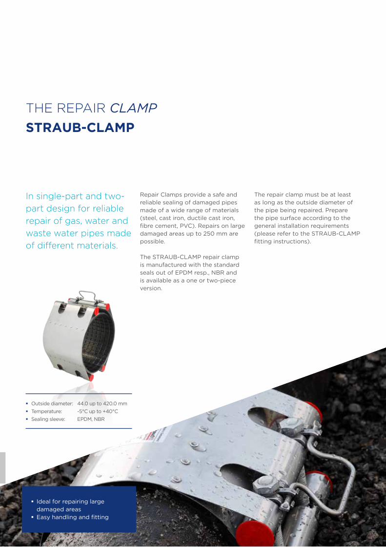
78
THE REPAIR CLAMP
STRAUB-CLAMP
In single-part and two-
part design for reliable
repair of gas, water and
waste water pipes made
of different materials.
Repair Clamps provide a safe and reliable sealing of damaged pipes made of a wide range of materials (steel, cast iron, ductile cast iron,fibre cement, PVC). Repairs on large damaged areas up to 250 mm are possible.
The STRAUB-CLAMP repair clamp is manufactured with the standard seals out of EPDM resp., NBR and is available as a one or two-piece version.
The repair clamp must be at least as long as the outside diameter of the pipe being repaired. Prepare the pipe surface according to the general installation requirements (please refer to the STRAUB-CLAMP fitting instructions).
� Outside diameter: 44.0 up to 420.0 mm
� Temperature: -5°C up to +40°C
� Sealing sleeve: EPDM, NBR
� Ideal for repairing large damaged areas
� Easy handling and fitting
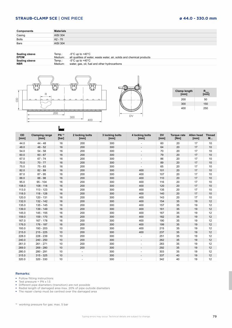
79
Components MaterialsCasing AISI 304Bolts A2 - 70Bars AISI 304
Sealing sleeve EPDM
Temp.:Medium:
-5°C up to +40°Call qualities of water, waste water, air, solids and chemical products
Sealing sleeve NBR
Temp.:Medium:
-5°C up to +40°Cwater, gas, oil, fuel and other hydrocarbons
OD[mm]
Clamping range[mm]
PN 13
[bar]2 locking bolts
[mm]3 locking bolts
[mm]4 locking bolts
[mm]DV
[mm]Torque rate
[Nm]Allen head
[mm]Thread
M...
44.0 44 - 48 16 200 300 - 60 20 17 1048.0 48 - 52 16 200 300 - 64 20 17 1054.0 54 - 58 16 200 300 - 70 20 17 1060.0 60 - 67 16 200 300 - 79 20 17 1067.0 67 - 74 16 200 300 - 86 20 17 1070.0 70 - 77 16 200 300 - 89 20 17 1075.0 75 - 83 16 200 300 - 65 20 17 1082.0 82 - 89 16 200 300 400 101 20 17 1087.0 87 - 95 16 200 300 400 107 20 17 1088.0 88 - 98 16 200 300 400 110 20 17 1095.0 95 - 104 16 200 300 400 116 20 17 10
108.0 108 - 118 16 200 300 400 120 20 17 10113.0 113 - 123 16 200 300 400 135 20 17 10118.0 118 - 128 16 200 300 400 140 20 17 10120.0 120 - 131 16 200 300 400 143 20 17 10132.0 132 - 142 16 200 300 400 154 35 19 12135.0 135 - 145 16 200 300 400 157 35 19 12139.0 139 - 149 16 200 300 400 161 35 19 12145.0 145 - 155 16 200 300 400 167 35 19 12159.0 159 - 170 16 200 300 400 182 35 19 12167.0 167 - 178 16 200 300 400 190 35 19 12176.0 176 - 187 16 200 300 400 199 35 19 12193.0 193 - 203 10 200 300 400 215 35 19 12215.0 215 - 225 10 200 300 400 237 35 19 12228.0 228 - 239 10 200 300 - 251 35 19 12 240.0 240 - 250 10 200 300 - 262 35 19 12 261.0 261 - 271 10 200 300 - 283 35 19 12 269.0 269 - 280 10 200 300 - 292 35 19 12280.0 280 - 291 10 - 300 - 303 35 19 12 315.0 315 - 325 10 - 300 - 337 40 19 12 320.0 320 - 330 10 - 300 - 342 40 19 12
Remarks:
� Follow fitting instructions � Test pressure = PN x 1.5 � Different pipe diameters (transition) are not possible � Radial length of damaged area max. 20% of pipe outside diameters � The repair clamp must be centred over the damaged area
13 working pressure for gas: max. 5 bar
DV400
300200
OD
RClamp length
[mm]Rmax
[mm]
200 50300 150400 250
Typing errors may occur. Technical details are subject to change.
STRAUB-CLAMP SCE | ONE PIECE ø 44.0 - 330.0 mm
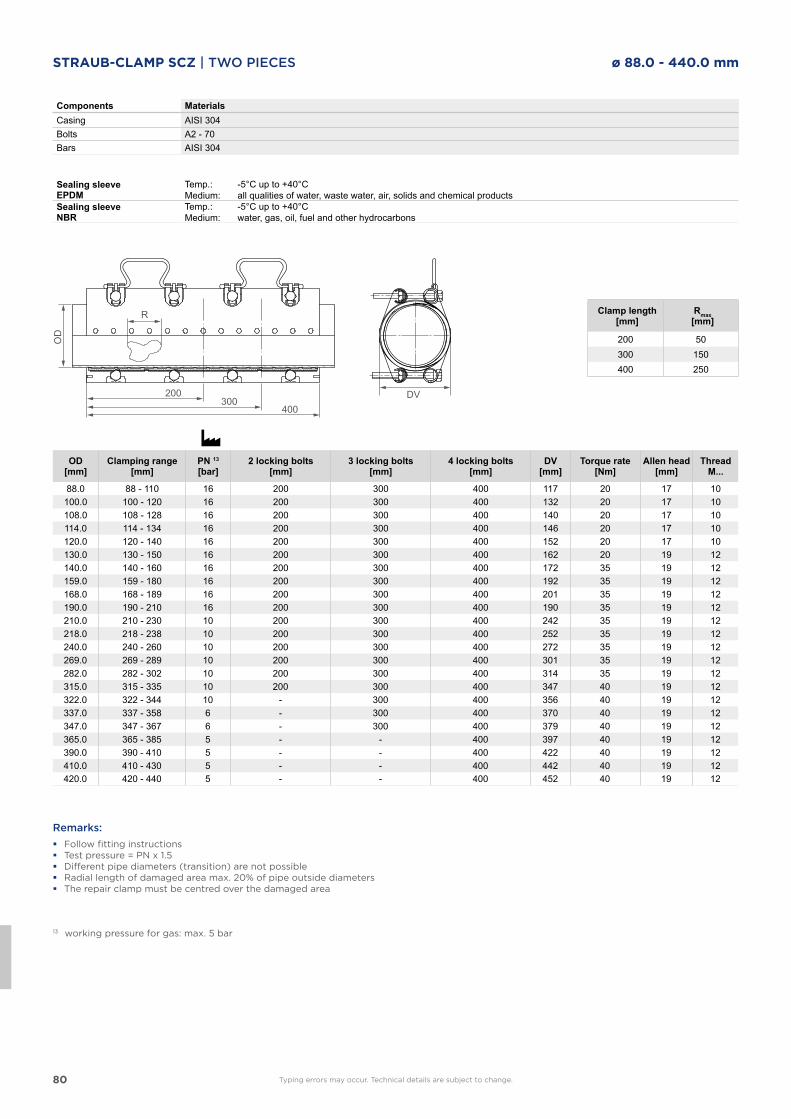
80
Components MaterialsCasing AISI 304Bolts A2 - 70Bars AISI 304
Sealing sleeve EPDM
Temp.:Medium:
-5°C up to +40°Call qualities of water, waste water, air, solids and chemical products
Sealing sleeve NBR
Temp.:Medium:
-5°C up to +40°Cwater, gas, oil, fuel and other hydrocarbons
Remarks:
� Follow fitting instructions � Test pressure = PN x 1.5 � Different pipe diameters (transition) are not possible � Radial length of damaged area max. 20% of pipe outside diameters � The repair clamp must be centred over the damaged area
13 working pressure for gas: max. 5 bar
OD[mm]
Clamping range[mm]
PN 13
[bar]2 locking bolts
[mm]3 locking bolts
[mm]4 locking bolts
[mm]DV
[mm]Torque rate
[Nm]Allen head
[mm]Thread
M...
88.0 88 - 110 16 200 300 400 117 20 17 10100.0 100 - 120 16 200 300 400 132 20 17 10108.0 108 - 128 16 200 300 400 140 20 17 10114.0 114 - 134 16 200 300 400 146 20 17 10120.0 120 - 140 16 200 300 400 152 20 17 10130.0 130 - 150 16 200 300 400 162 20 19 12140.0 140 - 160 16 200 300 400 172 35 19 12159.0 159 - 180 16 200 300 400 192 35 19 12168.0 168 - 189 16 200 300 400 201 35 19 12190.0 190 - 210 16 200 300 400 190 35 19 12210.0 210 - 230 10 200 300 400 242 35 19 12218.0 218 - 238 10 200 300 400 252 35 19 12240.0 240 - 260 10 200 300 400 272 35 19 12269.0 269 - 289 10 200 300 400 301 35 19 12282.0 282 - 302 10 200 300 400 314 35 19 12315.0 315 - 335 10 200 300 400 347 40 19 12322.0 322 - 344 10 - 300 400 356 40 19 12337.0 337 - 358 6 - 300 400 370 40 19 12347.0 347 - 367 6 - 300 400 379 40 19 12365.0 365 - 385 5 - - 400 397 40 19 12390.0 390 - 410 5 - - 400 422 40 19 12410.0 410 - 430 5 - - 400 442 40 19 12420.0 420 - 440 5 - - 400 452 40 19 12
DV400
300200
OD
R Clamp length[mm]
Rmax[mm]
200 50300 150400 250
Typing errors may occur. Technical details are subject to change.
STRAUB-CLAMP SCZ | TWO PIECES ø 88.0 - 440.0 mm
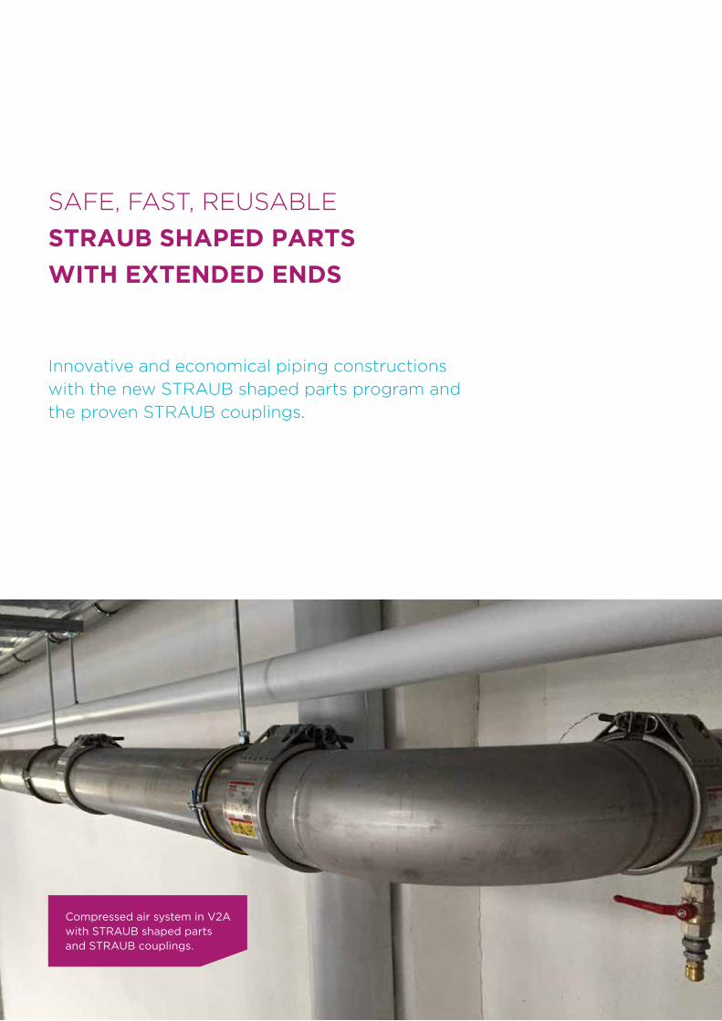
81
SAFE, FAST, REUSABLE
STRAUB SHAPED PARTS
WITH EXTENDED ENDS
Innovative and economical piping constructions
with the new STRAUB shaped parts program and
the proven STRAUB couplings.
Compressed air system in V2A with STRAUB shaped parts and STRAUB couplings.
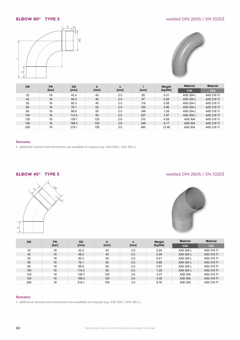
82
ELBOW 90° TYPE 3 welded DIN 2605 / EN 10253
DN PN[bar]
OD[mm]
b[mm]
s[mm]
l[mm]
Weight[kg/Stk]
Material Material V2A V4A
32 16 42.4 40 2.0 85 0.31 AISI 304 L AISI 316 TI40 16 48.3 40 2.0 97 0.39 AISI 304 L AISI 316 TI50 16 60.3 40 2.0 116 0.58 AISI 304 L AISI 316 TI65 16 76.1 55 2.0 150 0.96 AISI 304 L AISI 316 TI80 16 88.9 55 2.0 169 1.26 AISI 304 L AISI 316 TI100 16 114.3 55 2.0 207 1.97 AISI 304 L AISI 316 TI125 16 139.7 120 2.6 310 4.59 AISI 304 AISI 316 TI150 16 168.3 120 2.6 349 6.17 AISI 304 AISI 316 TI200 16 219.1 155 3.0 460 12.48 AISI 304 AISI 316 TI
ELBOW 45° TYPE 3 welded DIN 2605 / EN 10253
DN PN[bar]
OD[mm]
b[mm]
s[mm]
Weight[kg/Stk]
Material Material V2A V4A
32 16 42.4 40 2.0 0.24 AISI 304 L AISI 316 TI40 16 48.3 40 2.0 0.29 AISI 304 L AISI 316 TI50 16 60.3 40 2.0 0.41 AISI 304 L AISI 316 TI65 16 76.1 55 2.0 0.69 AISI 304 L AISI 316 TI80 16 88.9 55 2.0 0.87 AISI 304 L AISI 316 TI100 16 114.3 55 2.0 1.29 AISI 304 L AISI 316 TI125 16 139.7 120 2.6 3.37 AISI 304 AISI 316 TI150 16 168.3 120 2.6 4.38 AISI 304 AISI 316 TI200 16 219.1 155 3.0 8.76 AISI 304 AISI 316 TI
Remarks:
� additional versions and dimensions are available on request (e.g. AISI 304 / AISI 316 L)
Typing errors may occur. Technical details are subject to change.
Remarks:
� additional versions and dimensions are available on request (e.g. AISI 304 / AISI 316 L)
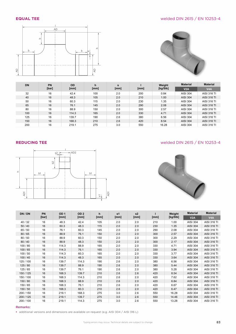
83
EQUAL TEE welded DIN 2615 / EN 10253-4
DN PN[bar]
OD[mm]
h[mm]
s[mm]
l[mm]
Weight[kg/Stk]
Material Material V2A V4A
32 16 42.4 100 2.0 200 0.84 AISI 304 AISI 316 TI40 16 48.3 105 2.0 210 1.00 AISI 304 AISI 316 TI50 16 60.3 115 2.0 230 1.35 AISI 304 AISI 316 TI65 16 76.1 145 2.0 290 2.08 AISI 304 AISI 316 TI80 16 88.9 150 2.0 300 2.57 AISI 304 AISI 316 TI100 16 114.3 165 2.0 330 4.71 AISI 304 AISI 316 TI125 16 139.7 190 2.6 380 6.56 AISI 304 AISI 316 TI150 16 168.3 210 2.6 420 8.54 AISI 304 AISI 316 TI200 16 219.1 275 3.0 550 16.28 AISI 304 AISI 316 TI
DN / DN PN[bar]
OD 1[mm]
OD 2[mm]
h[mm]
s1[mm]
s2[mm]
l[mm]
Weight[kg/Stk]
Material Material V2A V4A
40 / 32 16 48.3 42.4 105 2.0 2.0 210 1.00 AISI 304 AISI 316 TI50 / 40 16 60.3 48.3 115 2.0 2.0 230 1.35 AISI 304 AISI 316 TI65 / 50 16 76.1 60.3 145 2.0 2.0 290 2.08 AISI 304 AISI 316 TI80 / 65 16 88.9 76.1 150 2.0 2.0 300 2.57 AISI 304 AISI 316 TI80 / 50 16 88.9 60.3 150 2.0 2.0 300 2.29 AISI 304 AISI 316 TI80 / 40 16 88.9 48.3 150 2.0 2.0 300 2.17 AISI 304 AISI 316 TI100 / 80 16 114.3 88.9 165 2.0 2.0 330 4.71 AISI 304 AISI 316 TI100 / 65 16 114.3 76.1 165 2.0 2.0 330 3.94 AISI 304 AISI 316 TI100 / 50 16 114.3 60.3 165 2.0 2.0 330 3.77 AISI 304 AISI 316 TI100 / 40 16 114.3 48.3 165 2.0 2.0 330 3.64 AISI 304 AISI 316 TI125 / 100 16 139.7 114.3 190 2.6 2.0 380 6.56 AISI 304 AISI 316 TI125 / 80 16 139.7 88.9 190 2.6 2.0 380 5.44 AISI 304 AISI 316 TI125 / 65 16 139.7 76.1 190 2.6 2.0 380 5.28 AISI 304 AISI 316 TI150 / 125 16 168.3 139.7 210 2.6 2.6 420 8.54 AISI 304 AISI 316 TI150 / 100 16 168.3 114.3 210 2.6 2.0 420 7.62 AISI 304 AISI 316 TI150 / 80 16 168.3 88.9 210 2.6 2.0 420 6.84 AISI 304 AISI 316 TI150 / 65 16 168.3 76.1 210 2.6 2.0 420 6.67 AISI 304 AISI 316 TI150 / 50 16 168.3 60.3 210 2.6 2.0 420 6.47 AISI 304 AISI 316 TI200 / 150 16 219.1 168.3 275 3.0 2.6 550 16.28 AISI 304 AISI 316 TI200 / 125 16 219.1 139.7 275 3.0 2.6 550 14.46 AISI 304 AISI 316 TI200 / 100 16 219.1 114.3 275 3.0 2.6 550 13.28 AISI 304 AISI 316 TI
Remarks:
� additional versions and dimensions are available on request (e.g. AISI 304 / AISI 316 L)
REDUCING TEE welded DIN 2615 / EN 10253-4
2
Typing errors may occur. Technical details are subject to change.
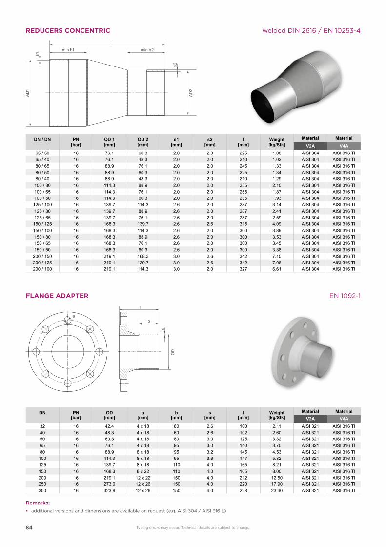
84
REDUCERS CONCENTRIC welded DIN 2616 / EN 10253-4
FLANGE ADAPTER EN 1092-1
DN PN[bar]
OD[mm]
a[mm]
b[mm]
s[mm]
l[mm]
Weight[kg/Stk]
Material Material V2A V4A
32 16 42.4 4 x 18 60 2.6 100 2.11 AISI 321 AISI 316 TI40 16 48.3 4 x 18 60 2.6 102 2.60 AISI 321 AISI 316 TI50 16 60.3 4 x 18 80 3.0 125 3.32 AISI 321 AISI 316 TI65 16 76.1 4 x 18 95 3.0 140 3.70 AISI 321 AISI 316 TI80 16 88.9 8 x 18 95 3.2 145 4.53 AISI 321 AISI 316 TI100 16 114.3 8 x 18 95 3.6 147 5.82 AISI 321 AISI 316 TI125 16 139.7 8 x 18 110 4.0 165 8.21 AISI 321 AISI 316 TI150 16 168.3 8 x 22 110 4.0 165 8.00 AISI 321 AISI 316 TI200 16 219.1 12 x 22 150 4.0 212 12.50 AISI 321 AISI 316 TI250 16 273.0 12 x 26 150 4.0 220 17.90 AISI 321 AISI 316 TI300 16 323.9 12 x 26 150 4.0 228 23.40 AISI 321 AISI 316 TI
min min 2
DN / DN PN[bar]
OD 1[mm]
OD 2[mm]
s1[mm]
s2[mm]
l[mm]
Weight[kg/Stk]
Material Material V2A V4A
65 / 50 16 76.1 60.3 2.0 2.0 225 1.08 AISI 304 AISI 316 TI65 / 40 16 76.1 48.3 2.0 2.0 210 1.02 AISI 304 AISI 316 TI80 / 65 16 88.9 76.1 2.0 2.0 245 1.33 AISI 304 AISI 316 TI80 / 50 16 88.9 60.3 2.0 2.0 225 1.34 AISI 304 AISI 316 TI80 / 40 16 88.9 48.3 2.0 2.0 210 1.29 AISI 304 AISI 316 TI100 / 80 16 114.3 88.9 2.0 2.0 255 2.10 AISI 304 AISI 316 TI100 / 65 16 114.3 76.1 2.0 2.0 255 1.87 AISI 304 AISI 316 TI100 / 50 16 114.3 60.3 2.0 2.0 235 1.93 AISI 304 AISI 316 TI125 / 100 16 139.7 114.3 2.6 2.0 287 3.14 AISI 304 AISI 316 TI125 / 80 16 139.7 88.9 2.6 2.0 287 2.41 AISI 304 AISI 316 TI125 / 65 16 139.7 76.1 2.6 2.0 287 2.59 AISI 304 AISI 316 TI
150 / 125 16 168.3 139.7 2.6 2.6 315 4.09 AISI 304 AISI 316 TI150 / 100 16 168.3 114.3 2.6 2.0 300 3.89 AISI 304 AISI 316 TI150 / 80 16 168.3 88.9 2.6 2.0 300 3.53 AISI 304 AISI 316 TI150 / 65 16 168.3 76.1 2.6 2.0 300 3.45 AISI 304 AISI 316 TI150 / 50 16 168.3 60.3 2.6 2.0 300 3.38 AISI 304 AISI 316 TI
200 / 150 16 219.1 168.3 3.0 2.6 342 7.15 AISI 304 AISI 316 TI200 / 125 16 219.1 139.7 3.0 2.6 342 7.06 AISI 304 AISI 316 TI200 / 100 16 219.1 114.3 3.0 2.0 327 6.61 AISI 304 AISI 316 TI
OD
a
Remarks:
� additional versions and dimensions are available on request (e.g. AISI 304 / AISI 316 L)
Typing errors may occur. Technical details are subject to change.
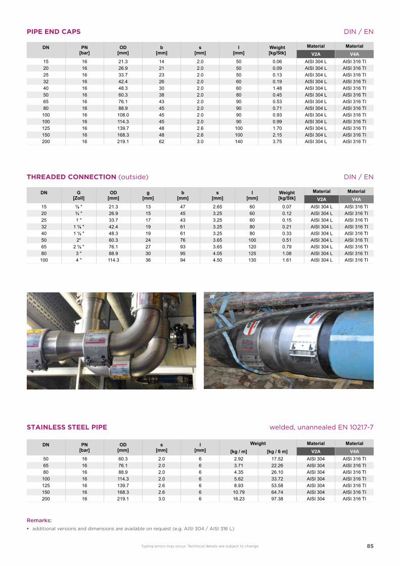
85
PIPE END CAPS DIN / EN
DN PN[bar]
OD[mm]
b[mm]
s[mm]
l[mm]
Weight[kg/Stk]
Material Material V2A V4A
15 16 21.3 14 2.0 50 0.06 AISI 304 L AISI 316 TI20 16 26.9 21 2.0 50 0.09 AISI 304 L AISI 316 TI25 16 33.7 23 2.0 50 0.13 AISI 304 L AISI 316 TI32 16 42.4 26 2.0 60 0.19 AISI 304 L AISI 316 TI40 16 48.3 30 2.0 60 1.48 AISI 304 L AISI 316 TI50 16 60.3 38 2.0 80 0.45 AISI 304 L AISI 316 TI65 16 76.1 43 2.0 90 0.53 AISI 304 L AISI 316 TI80 16 88.9 45 2.0 90 0.71 AISI 304 L AISI 316 TI100 16 108.0 45 2.0 90 0.93 AISI 304 L AISI 316 TI100 16 114.3 45 2.0 90 0.99 AISI 304 L AISI 316 TI125 16 139.7 48 2.6 100 1.70 AISI 304 L AISI 316 TI150 16 168.3 48 2.6 100 2.15 AISI 304 L AISI 316 TI200 16 219.1 62 3.0 140 3.75 AISI 304 L AISI 316 TI
DN G[Zoll]
OD[mm]
g[mm]
b[mm]
s[mm]
l[mm]
Weight[kg/Stk]
Material Material V2A V4A
15 ½ " 21.3 13 47 2.65 60 0.07 AISI 304 L AISI 316 TI20 ¾ " 26.9 15 45 3.25 60 0.12 AISI 304 L AISI 316 TI25 1 " 33.7 17 43 3.25 60 0.15 AISI 304 L AISI 316 TI32 1 ¼ " 42.4 19 61 3.25 80 0.21 AISI 304 L AISI 316 TI40 1 ½ " 48.3 19 61 3.25 80 0.33 AISI 304 L AISI 316 TI50 2" 60.3 24 76 3.65 100 0.51 AISI 304 L AISI 316 TI65 2 ½ " 76.1 27 93 3.65 120 0.79 AISI 304 L AISI 316 TI80 3 " 88.9 30 95 4.05 125 1.08 AISI 304 L AISI 316 TI
100 4 " 114.3 36 94 4.50 130 1.61 AISI 304 L AISI 316 TI
THREADED CONNECTION (outside) DIN / EN
DN PN[bar]
OD[mm]
s[mm]
l[mm]
Weight Material Material [kg / m] [kg / 6 m] V2A V4A
50 16 60.3 2.0 6 2.92 17.52 AISI 304 AISI 316 TI65 16 76.1 2.0 6 3.71 22.26 AISI 304 AISI 316 TI80 16 88.9 2.0 6 4.35 26.10 AISI 304 AISI 316 TI
100 16 114.3 2.0 6 5.62 33.72 AISI 304 AISI 316 TI125 16 139.7 2.6 6 8.93 53.58 AISI 304 AISI 316 TI150 16 168.3 2.6 6 10.79 64.74 AISI 304 AISI 316 TI200 16 219.1 3.0 6 16.23 97.38 AISI 304 AISI 316 TI
STAINLESS STEEL PIPE welded, unannealed EN 10217-7
Remarks:
� additional versions and dimensions are available on request (e.g. AISI 304 / AISI 316 L)
Typing errors may occur. Technical details are subject to change.
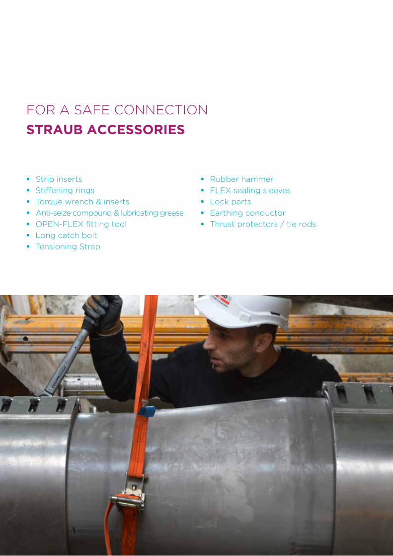
86
FOR A SAFE CONNECTION
STRAUB ACCESSORIES
� Strip inserts
� Stiffening rings
� Torque wrench & inserts
� Anti-seize compound & lubricating grease
� OPEN-FLEX fitting tool
� Long catch bolt
� Tensioning Strap
� Rubber hammer
� FLEX sealing sleeves
� Lock parts
� Earthing conductor
� Thrust protectors / tie rods
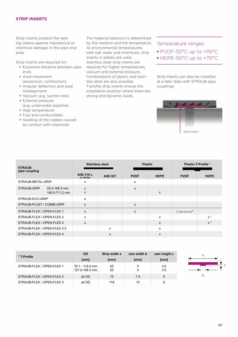
87
a
b
c
STRIP INSERTS
Strip inserts protect the seal-ing sleeve against mechanical or chemi cal damage in the pipe end area.
Strip inserts are required for: � Excessive distance between pipe ends
� Axial movement (expansion, contraction)
� Angular deflection and axial misalignment
� Vacuum (e.g. suction line) � External pressure (e.g. underwater pipeline)
� High temperature � Fuel and combustibles � Swelling of the rubber caused by contact with chemicals
Strip insert
Temperature ranges:
� PVDF-30°C up to +115°C
� HDPE-50°C up to +70°C
The material selection is determined by the medium and the temperature. At environmental temperatures, with salt water and chemicals, strip inserts in plastic are used. Stainless steel strip inserts are required for higher temperatures, vacuum and external pressure. Combinations of plastic and stain-less steel are also possible. T-profile strip inserts ensure the installation position where there are strong and dynamic loads.
Strip inserts can also be installed at a later date with STRAUB pipe couplings.
STRAUBpipe coupling
Stainless steel Plastic Plastic-T-Profile *
AISI 316 L AISI 301 PVDF HDPE PVDF HDPEor similar
STRAUB-METAL-GRIP x x
STRAUB-GRIP 25.0-168.3 mm 180.0-711.2 mm
xx
xx
STRAUB-ECO-GRIP x
STRAUB-PLAST / COMBI-GRIP x x
STRAUB-FLEX / OPEN-FLEX 1 x x x (from 76.1mm)*
STRAUB-FLEX / OPEN-FLEX 2 x x x *
STRAUB-FLEX / OPEN-FLEX 3 x x x *
STRAUB-FLEX / OPEN-FLEX 3.5 x x
STRAUB-FLEX / OPEN-FLEX 4 x x
* T-ProfileOD Strip width a cam width b cam height c
[mm] [mm] [mm] [mm]
STRAUB-FLEX / OPEN-FLEX 1 76.1 - 118.0 mm127.0-168.3 mm
4555
55
3.53.5
STRAUB-FLEX / OPEN-FLEX 2 all OD 75 7.5 6
STRAUB-FLEX / OPEN-FLEX 3 all OD 118 10 6
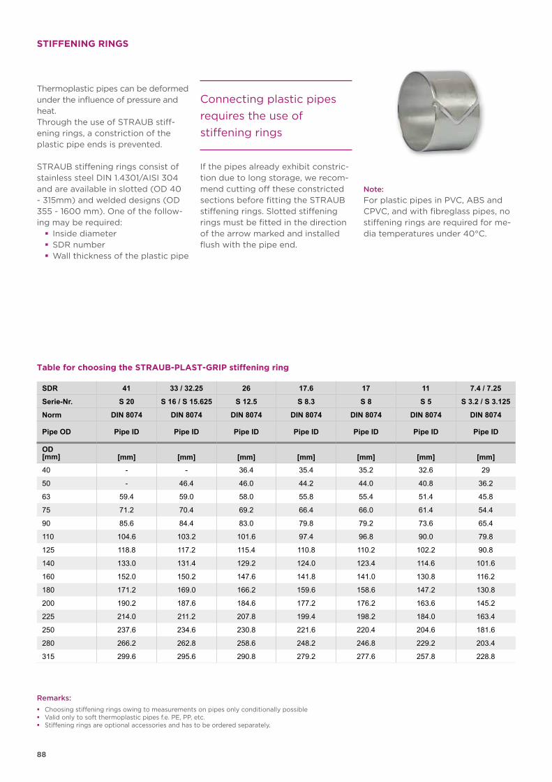
88
STIFFENING RINGS
Connecting plastic pipes
requires the use of
stiffening rings
Table for choosing the STRAUB-PLAST-GRIP stiffening ring
Remarks:
� Choosing stiffening rings owing to measurements on pipes only conditionally possible � Valid only to soft thermoplastic pipes f.e. PE, PP, etc. � Stiffening rings are optional accessories and has to be ordered separately.
Thermoplastic pipes can be deformed under the influence of pressure and heat. Through the use of STRAUB stiff-ening rings, a constriction of the plastic pipe ends is prevented.
STRAUB stiffening rings consist of stainless steel DIN 1.4301/AISI 304 and are available in slotted (OD 40 - 315mm) and welded designs (OD 355 - 1600 mm). One of the follow-ing may be required:
� Inside diameter � SDR number � Wall thickness of the plastic pipe
If the pipes already exhibit constric-tion due to long storage, we recom-mend cutting off these constricted sections before fitting the STRAUB stiffening rings. Slotted stiffening rings must be fitted in the direction of the arrow marked and installed flush with the pipe end.
Note:
For plastic pipes in PVC, ABS and CPVC, and with fibreglass pipes, no stiffening rings are required for me-dia temperatures under 40°C.
SDR 41 33 / 32.25 26 17.6 17 11 7.4 / 7.25
Serie-Nr. S 20 S 16 / S 15.625 S 12.5 S 8.3 S 8 S 5 S 3.2 / S 3.125
Norm DIN 8074 DIN 8074 DIN 8074 DIN 8074 DIN 8074 DIN 8074 DIN 8074
Pipe OD Pipe ID Pipe ID Pipe ID Pipe ID Pipe ID Pipe ID Pipe ID
OD[mm] [mm] [mm] [mm] [mm] [mm] [mm] [mm]
40 - - 36.4 35.4 35.2 32.6 29
50 - 46.4 46.0 44.2 44.0 40.8 36.2
63 59.4 59.0 58.0 55.8 55.4 51.4 45.8
75 71.2 70.4 69.2 66.4 66.0 61.4 54.4
90 85.6 84.4 83.0 79.8 79.2 73.6 65.4
110 104.6 103.2 101.6 97.4 96.8 90.0 79.8
125 118.8 117.2 115.4 110.8 110.2 102.2 90.8
140 133.0 131.4 129.2 124.0 123.4 114.6 101.6
160 152.0 150.2 147.6 141.8 141.0 130.8 116.2
180 171.2 169.0 166.2 159.6 158.6 147.2 130.8
200 190.2 187.6 184.6 177.2 176.2 163.6 145.2
225 214.0 211.2 207.8 199.4 198.2 184.0 163.4
250 237.6 234.6 230.8 221.6 220.4 204.6 181.6
280 266.2 262.8 258.6 248.2 246.8 229.2 203.4
315 299.6 295.6 290.8 279.2 277.6 257.8 228.8
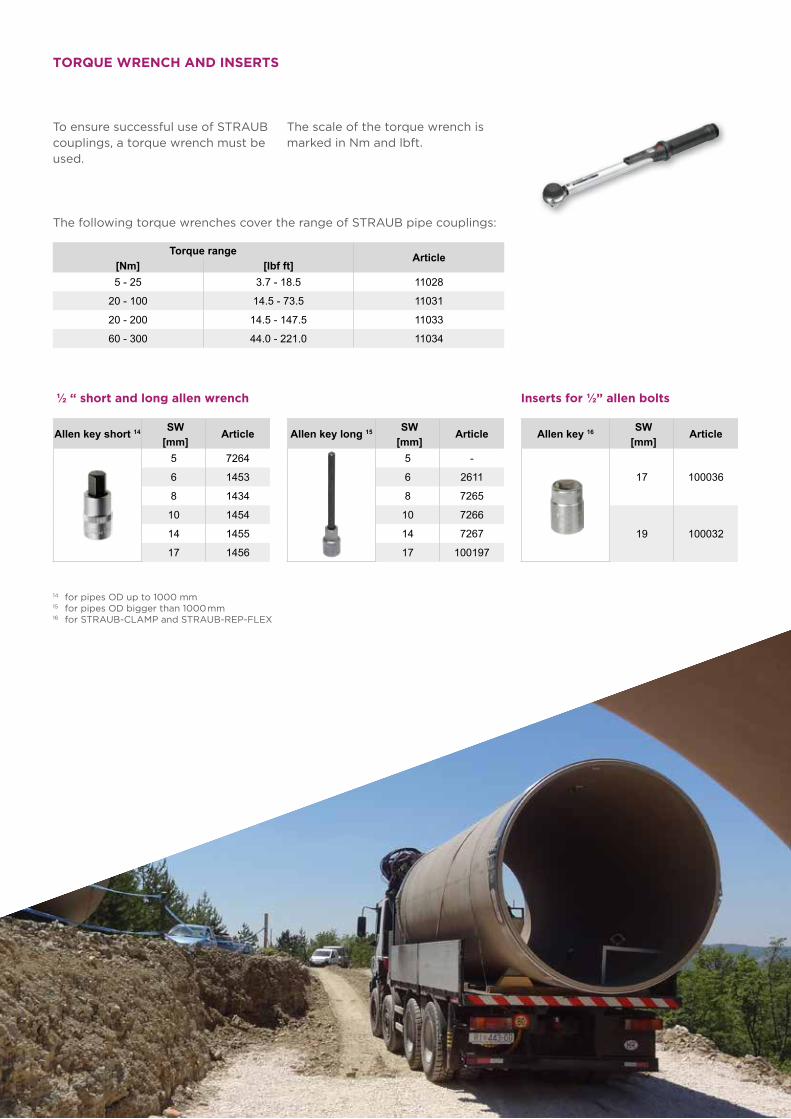
89
TORQUE WRENCH AND INSERTS
To ensure successful use of STRAUB couplings, a torque wrench must be used.
The scale of the torque wrench is marked in Nm and lbft.
Torque range Article[Nm] [lbf ft]5 - 25 3.7 - 18.5 11028
20 - 100 14.5 - 73.5 11031
20 - 200 14.5 - 147.5 11033
60 - 300 44.0 - 221.0 11034
Allen key long 15 SW Article[mm]
5 -
6 2611
8 7265
10 7266
14 7267
17 100197
Allen key 16 SW Article[mm]
17 100036
19 100032
Allen key short 14 SW Article[mm]
5 7264
6 1453
8 1434
10 1454
14 1455
17 1456
½ “ short and long allen wrench Inserts for ½” allen bolts
14 for pipes OD up to 1000 mm15 for pipes OD bigger than 1000 mm16 for STRAUB-CLAMP and STRAUB-REP-FLEX
The following torque wrenches cover the range of STRAUB pipe couplings:
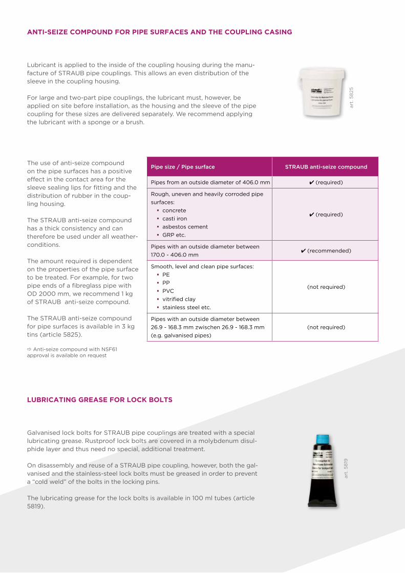
90
Galvanised lock bolts for STRAUB pipe couplings are treated with a special lubricating grease. Rustproof lock bolts are covered in a molybdenum disul-phide layer and thus need no special, additional treatment.
On disassembly and reuse of a STRAUB pipe coupling, however, both the gal-vanised and the stainless-steel lock bolts must be greased in order to prevent a “cold weld” of the bolts in the locking pins.
The lubricating grease for the lock bolts is available in 100 ml tubes (article 5819).
LUBRICATING GREASE FOR LOCK BOLTS
Lubricant is applied to the inside of the coupling housing during the manu-facture of STRAUB pipe coup lings. This allows an even distribution of the sleeve in the coupling housing.
For large and two-part pipe coup lings, the lubricant must, however, be applied on site before installation, as the housing and the sleeve of the pipe coupling for these sizes are delivered separately. We recommend applying the lubricant with a sponge or a brush.
ANTI-SEIZE COMPOUND FOR PIPE SURFACES AND THE COUPLING CASING
The use of anti-seize compound on the pipe surfaces has a positive effect in the contact area for the sleeve sealing lips for fitting and the distribution of rubber in the coup-ling housing.
The STRAUB anti-seize compound has a thick consistency and can therefore be used under all weather-conditions.
The amount required is dependent on the properties of the pipe surface to be treated. For example, for two pipe ends of a fibreglass pipe with OD 2000 mm, we recommend 1 kg of STRAUB anti-seize compound.
The STRAUB anti-seize compound for pipe surfaces is available in 3 kg tins (article 5825).
Anti-seize compound with NSF61 approval is available on request
Pipe size / Pipe surface STRAUB anti-seize compound
Pipes from an outside diameter of 406.0 mm 4 (required)
Rough, uneven and heavily corroded pipe
surfaces:
� concrete
� casti iron
� asbestos cement
� GRP etc.
4 (required)
Pipes with an outside diameter between
170.0 - 406.0 mm4 (recommended)
Smooth, level and clean pipe surfaces:
� PE
� PP
� PVC
� vitrified clay
� stainless steel etc.
(not required)
Pipes with an outside diameter between
26.9 - 168.3 mm zwischen 26.9 - 168.3 mm
(e.g. galvanised pipes)
(not required)
art
. 5
819
art
. 5
825
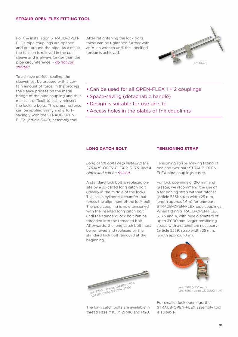
91
STRAUB-OPEN-FLEX FITTING TOOL
For the installation STRAUB-OPEN-FLEX pipe couplings are opened and put around the pipe. As a result the tension is relieved in the cut sleeve and is always longer than the pipe circumference - do not cut shorter!
To achieve perfect sealing, the sleevemust be pressed with a cer-tain amount of force. In the process, the sleeve presses on the metal bridge of the pipe coupling and thus makes it difficult to easily reinsert the locking bolts. This pressing force can be applied easily and effort- savingly with the STRAUB OPEN-FLEX (article 6649) assembly tool.
After retightening the lock bolts, these can be tightened further with an Allen wrench until the specified torque is achieved.
� Can be used for all OPEN-FLEX 1 + 2 couplings
� Space-saving (detachable handle)
� Design is suitable for use on site
� Access holes in the plates of the couplings
art. 6649
Tensioning straps making fitting of one and two-part STRAUB-OPEN-FLEX pipe couplings easier.
For lock openings of 210 mm and greater, we recommend the use of a tensioning strap without ratchet (article 5561: strap width 25 mm, length approx. 1.6m) for one-part STRAUB-OPEN-FLEX pipe couplings. When fitting STRAUB-OPEN-FLEX 3, 3.5 and 4, with pipe diameters of up to 3’000 mm, larger tensioning straps with a ratchet are necessary (article 5559: strap width 35 mm, length approx. 10 m).
Long catch bolts help installing the STRAUB-OPEN-FLEX 2, 3, 3.5, and 4 types and can be reused.
A standard lock bolt is replaced on-site by a so-called long catch bolt (ideally in the middle of the lock). This has a cylindrical chamfer that forces the alignment of the lock bolt. The pipe coupling is now tensioned with the inserted long catch bolt until the standard lock bolt can be threaded into the threaded bolt. Afterwards, the long catch bolt must be removed and replaced by the standard lock bolt removed at the beginning.
LONG CATCH BOLT TENSIONING STRAP
art. 5561 (<210 mm)art. 5559 (up to OD 3000 mm)
The long catch bolts are available in thread sizes M10, M12, M16 and M20.
For smaller lock openings, the STRAUB-OPEN-FLEX assembly tool is suitable.
art. 5943P1 (M10), 5943P2 (M12),
5943P3 (M16), 5943P4 (M20)
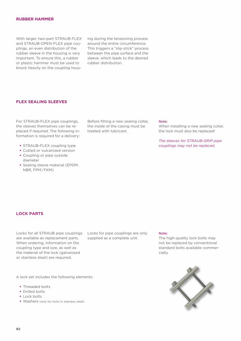
92
LOCK PARTS
Locks for all STRAUB pipe couplings are available as replacement parts. When ordering, information on the coupling type and size, as well as the material of the lock (galvanisedor stainless steel) are required.
Locks for pipe couplings are only supplied as a complete unit.
Note:
The high-quality lock bolts may not be replaced by conventional standard bolts available commer-cially.
A lock set includes the following elements:
� Threaded bolts � Drilled bolts � Lock bolts � Washers (only for locks in stainless steel)
For STRAUB-FLEX pipe couplings, the sleeves themselves can be re-placed if required. The following in-formation is required for a delivery:
� STRAUB-FLEX coupling type � Cutted or vulcanized version � Coupling or pipe outside diameter
� Sealing sleeve material (EPDM, NBR, FPM / FKM)
FLEX SEALING SLEEVES
Before fitting a new sealing collar, the inside of the casing must be treated with lubricant.
Note:
When installing a new sealing collar, the lock must also be replaced!
The sleeves for STRAUB-GRIP pipe couplings may not be replaced.
With larger, two-part STRAUB-FLEX and STRAUB-OPEN-FLEX pipe cou-plings, an even distribution of the rubber sleeve in the housing is very important. To ensure this, a rubber or plastic hammer must be used to knock heavily on the coupling hous-
RUBBER HAMMER
ing during the tensioning process around the entire circumference. This triggers a “slip-stick” process between the pipe surface and the sleeve, which leads to the desired rubber distribution.
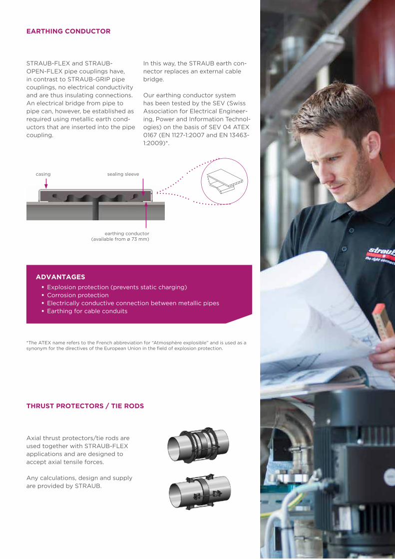
93
EARTHING CONDUCTOR
STRAUB-FLEX and STRAUB-OPEN-FLEX pipe couplings have, in contrast to STRAUB-GRIP pipe couplings, no electrical conductivity and are thus insulating connections. An electrical bridge from pipe to pipe can, however, be established as required using metallic earth cond-uctors that are inserted into the pipe coupling.
*The ATEX name refers to the French abbreviation for “Atmosphère explosible” and is used as a synonym for the directives of the European Union in the field of explosion protection.
ADVANTAGES
� Explosion protection (prevents static charging) � Corrosion protection � Electrically conductive connection between metallic pipes � Earthing for cable conduits
casing sealing sleeve
earthing conductor(available from ø 73 mm)
Axial thrust protectors/tie rods are used together with STRAUB-FLEX applications and are designed to accept axial tensile forces.
Any calculations, design and supply are provided by STRAUB.
THRUST PROTECTORS / TIE RODS
In this way, the STRAUB earth con-nector replaces an external cable bridge.
Our earthing conductor system has been tested by the SEV (Swiss Association for Electrical Engineer-ing, Power and Information Technol-ogies) on the basis of SEV 04 ATEX 0167 (EN 1127-1:2007 and EN 13463-1:2009)*.
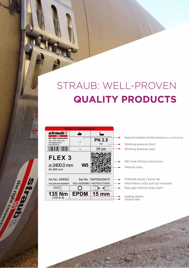
94
*118*
Made in Switzerland
- PN 2.5bar
Tel. + 41 81 725 41 [email protected]
- 58 psi
FLEX 3ø 2400.0 mm W594.488 inch
Art.No. 658062 Ser.No. 109792020915 not pull-out-resistant SEE ASSEMBLY INSTRUCTIONS
135 Nm[100 lb.ft]
EPDM 15 mm
Approval-related nominal pressure (e.g. shipbuilding)
Working pressure [bar]
Working pressure [psi]
QR Code (fitting instruction)
Material class
STRAUB article | Serial No.
Information (not) pull-out-resistant
Pipe gap without strip insert
Sealing sleeveTorque rate
STRAUB: WELL-PROVEN
QUALITY PRODUCTS

95
STRAUB
INSTALLATION INSTRUCTIONS
A unique principle, but countless possible
applications. Cost effectiveness and reliability,
also under the harshest conditions, are our top
priorities.
Correct application is the prerequisite to be
able to utilise all advantages of the STRAUB
technology.
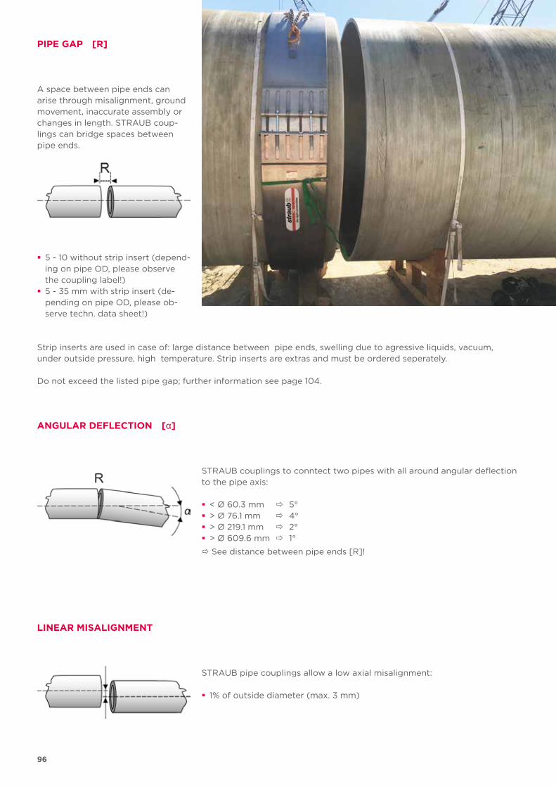
96
PIPE GAP [R]
A space between pipe ends can arise through misalignment, ground movement, inaccurate assembly or changes in length. STRAUB coup-lings can bridge spaces between pipe ends.
� 5 - 10 without strip insert (depend-ing on pipe OD, please observe the coupling label!)
� 5 - 35 mm with strip insert (de-pending on pipe OD, please ob-serve techn. data sheet!)
Strip inserts are used in case of: large distance between pipe ends, swelling due to agressive liquids, vacuum, under outside pressure, high temperature. Strip inserts are extras and must be ordered seperately.
Do not exceed the listed pipe gap; further information see page 104.
ANGULAR DEFLECTION [α]
STRAUB couplings to conntect two pipes with all around angular deflection to the pipe axis:
� < Ø 60.3 mm 5° � > Ø 76.1 mm 4° � > Ø 219.1 mm 2° � > Ø 609.6 mm 1°
See distance between pipe ends [R]!
LINEAR MISALIGNMENT
STRAUB pipe couplings allow a low axial misalignment:
� 1% of outside diameter (max. 3 mm)
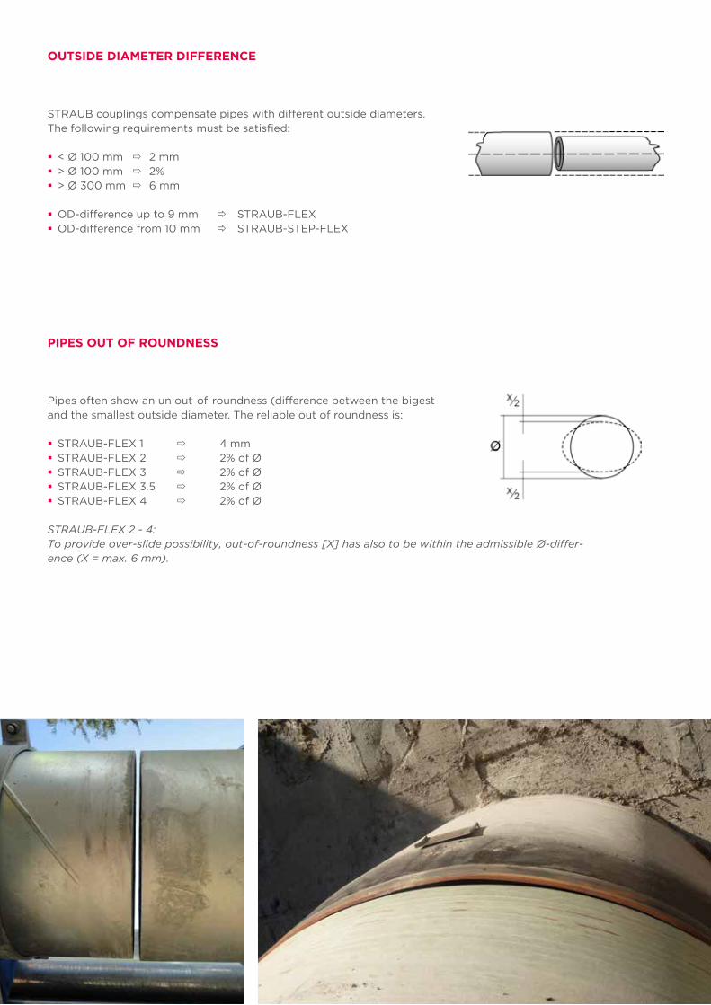
97
OUTSIDE DIAMETER DIFFERENCE
STRAUB couplings compensate pipes with different outside diameters. The following requirements must be satisfied:
� < Ø 100 mm 2 mm � > Ø 100 mm 2% � > Ø 300 mm 6 mm
� OD-difference up to 9 mm STRAUB-FLEX � OD-difference from 10 mm STRAUB-STEP-FLEX
Pipes often show an un out-of-roundness (difference between the bigest and the smallest outside diameter. The reliable out of roundness is:
� STRAUB-FLEX 1 4 mm � STRAUB-FLEX 2 2% of Ø � STRAUB-FLEX 3 2% of Ø � STRAUB-FLEX 3.5 2% of Ø � STRAUB-FLEX 4 2% of Ø
PIPES OUT OF ROUNDNESS
STRAUB-FLEX 2 - 4: To provide over-slide possibility, out-of-roundness [X] has also to be within the admissible Ø-differ-ence (X = max. 6 mm).
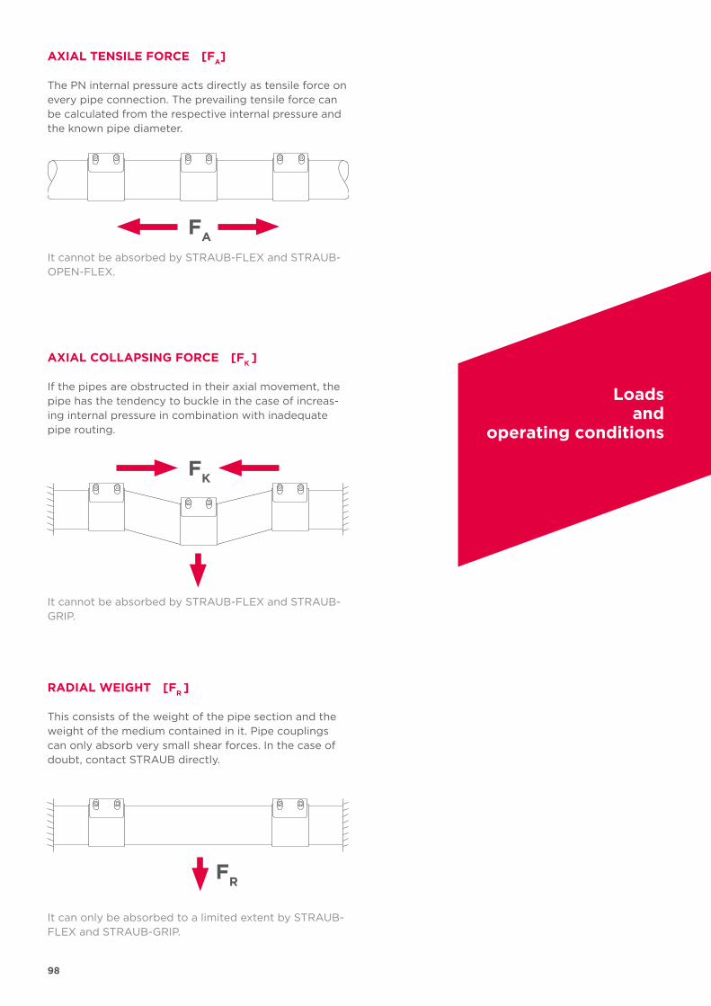
98
FA
FK
FR
AXIAL TENSILE FORCE [FA]
AXIAL COLLAPSING FORCE [FK
]
The PN internal pressure acts directly as tensile force on every pipe connection. The prevailing tensile force can be calculated from the respective internal pressure and the known pipe diameter.
If the pipes are obstructed in their axial movement, the pipe has the tendency to buckle in the case of increas-ing internal pressure in combination with inadequate pipe routing.
RADIAL WEIGHT [FR ]
This consists of the weight of the pipe section and the weight of the medium contained in it. Pipe couplings can only absorb very small shear forces. In the case of doubt, contact STRAUB directly.
It cannot be absorbed by STRAUB-FLEX and STRAUB-OPEN-FLEX.
It cannot be absorbed by STRAUB-FLEX and STRAUB-GRIP.
It can only be absorbed to a limited extent by STRAUB-FLEX and STRAUB-GRIP.
Loads and
operating conditions
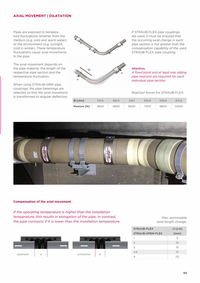
99
ba
Ø [mm] 101.6 168.0 219.1 355.6 558.8 812.8
Newton [N] 3800 4800 5600 7300 9800 12500
STRAUB-FLEX ∆l (a-b)
STRAUB-OPEN-FLEX [mm]
1 5
2 10
3 15
3.5 15
4 20
AXIAL MOVEMENT | DILATATION
Pipes are exposed to tempera-ture fluctuations whether from the medium (e.g. cold and warm water) or the environment (e.g. sunlight, cold in winter). These temperature fluctuations cause axial movements in the pipe.
The axial movement depends on the pipe material, the length of the respective pipe section and the temp erature fluctuation.
When using STRAUB-GRIP pipe couplings, the pipe fastenings are selected so that the axial movement is transformed to angular deflection.
Attention:
A fixed point and at least one sliding pipe restraint are required for each individual pipe section.
contractionexpansion
If STRAUB-FLEX pipe couplings are used, it must be ensured that the occurring axial change in each pipe section is not greater than the compensation capability of the used STRAUB-FLEX pipe coupling.
If the operating temperature is higher than the installation
temperature, this results in elongation of the pipe. In contrast,
the pipe contracts if it is lower than the installation temperature.
Compensation of the axial movement
Reaction forces for STRAUB-FLEX:
Max. permissible axial length change:
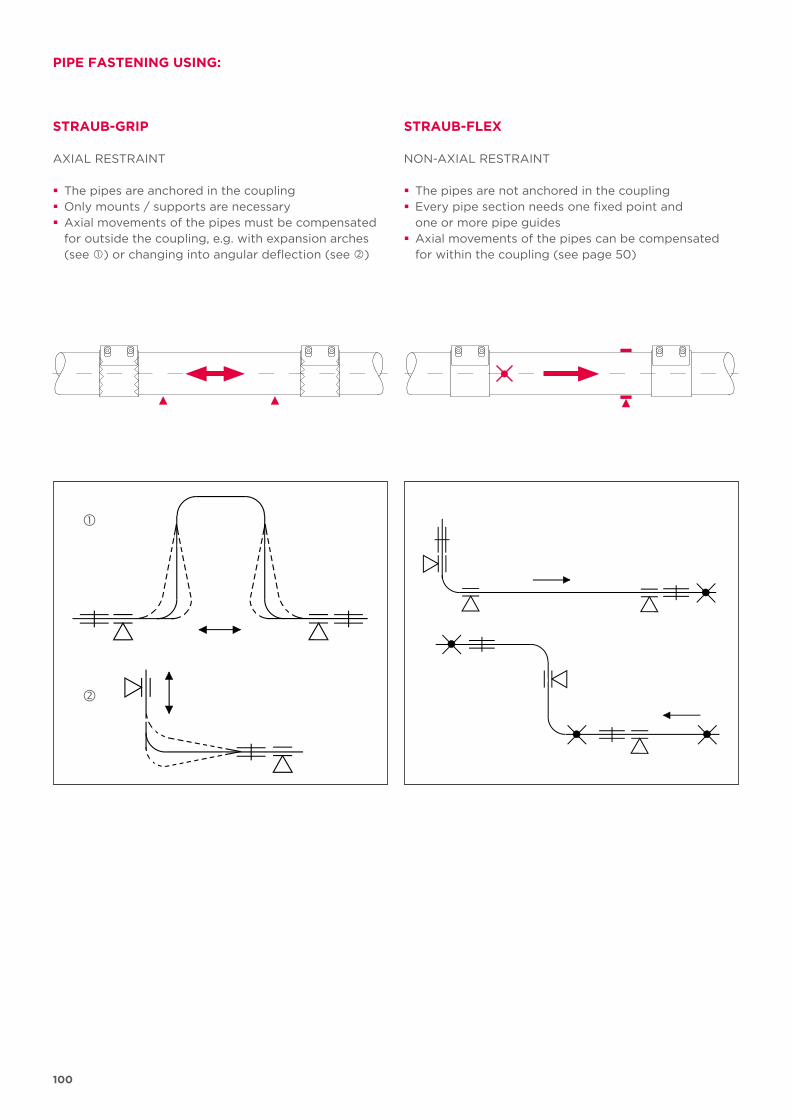
100
STRAUB-GRIP
PIPE FASTENING USING:
STRAUB-FLEX
NON-AXIAL RESTRAINT
� The pipes are not anchored in the coupling � Every pipe section needs one fixed point and one or more pipe guides
� Axial movements of the pipes can be compensated for within the coupling (see page 50)
AXIAL RESTRAINT
� The pipes are anchored in the coupling � Only mounts / supports are necessary � Axial movements of the pipes must be compensated for outside the coupling, e.g. with expansion arches (see ) or changing into angular deflection (see )
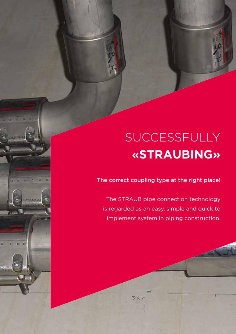
101
SUCCESSFULLY
«STRAUBING»
The correct coupling type at the right place!
The STRAUB pipe connection technology
is regarded as an easy, simple and quick to
implement system in piping construction.
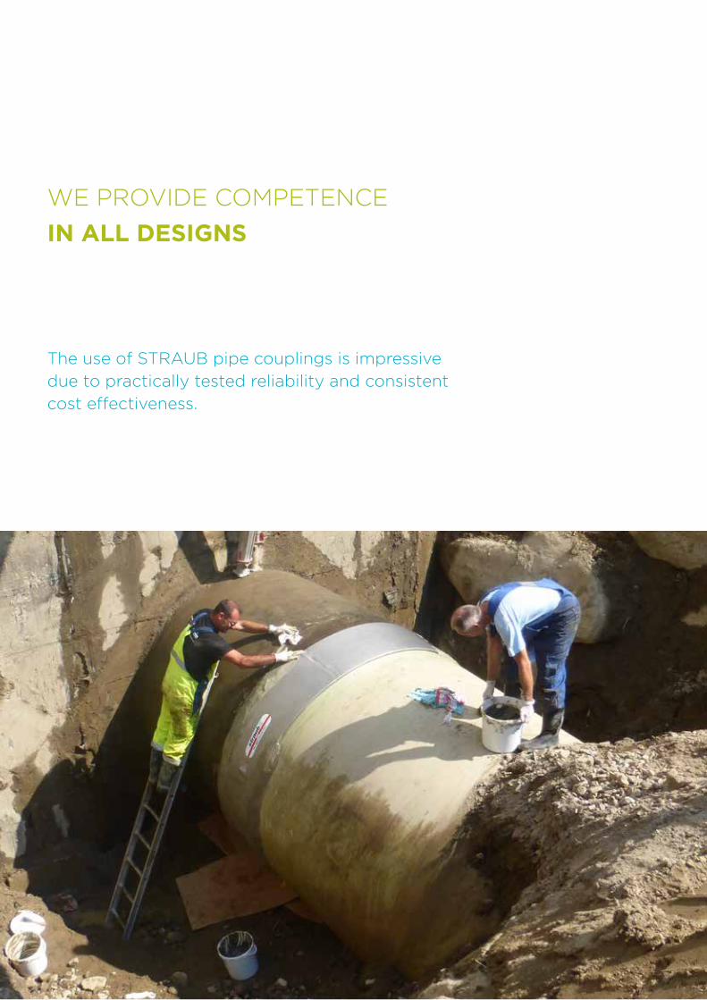
102
WE PROVIDE COMPETENCE
IN ALL DESIGNS
The use of STRAUB pipe couplings is impressive
due to practically tested reliability and consistent
cost effectiveness.
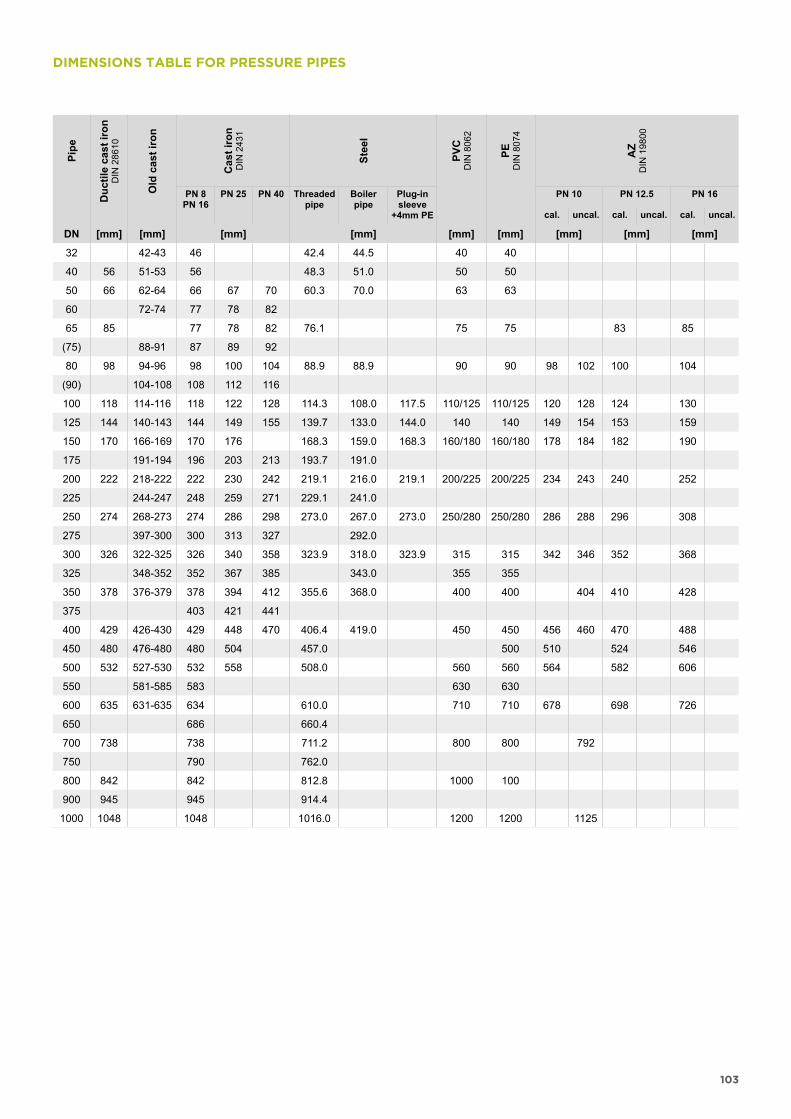
103
DIMENSIONS TABLE FOR PRESSURE PIPESPi
pe
Duc
tile
cast
iron
D
IN 2
8610
Old
cas
t iro
n
Cas
t iro
nD
IN 2
431
Stee
l
PVC
DIN
806
2
PED
IN 8
074
AZ
DIN
198
00
PN 8PN 16
PN 25 PN 40 Threaded pipe
Boiler pipe
Plug-in sleeve
+4mm PE
PN 10 PN 12.5 PN 16
cal. uncal. cal. uncal. cal. uncal.
DN [mm] [mm] [mm] [mm] [mm] [mm] [mm] [mm] [mm]
32 42-43 46 42.4 44.5 40 40
40 56 51-53 56 48.3 51.0 50 50
50 66 62-64 66 67 70 60.3 70.0 63 63
60 72-74 77 78 82
65 85 77 78 82 76.1 75 75 83 85
(75) 88-91 87 89 92
80 98 94-96 98 100 104 88.9 88.9 90 90 98 102 100 104
(90) 104-108 108 112 116
100 118 114-116 118 122 128 114.3 108.0 117.5 110/125 110/125 120 128 124 130
125 144 140-143 144 149 155 139.7 133.0 144.0 140 140 149 154 153 159
150 170 166-169 170 176 168.3 159.0 168.3 160/180 160/180 178 184 182 190
175 191-194 196 203 213 193.7 191.0
200 222 218-222 222 230 242 219.1 216.0 219.1 200/225 200/225 234 243 240 252
225 244-247 248 259 271 229.1 241.0
250 274 268-273 274 286 298 273.0 267.0 273.0 250/280 250/280 286 288 296 308
275 397-300 300 313 327 292.0
300 326 322-325 326 340 358 323.9 318.0 323.9 315 315 342 346 352 368
325 348-352 352 367 385 343.0 355 355
350 378 376-379 378 394 412 355.6 368.0 400 400 404 410 428
375 403 421 441
400 429 426-430 429 448 470 406.4 419.0 450 450 456 460 470 488
450 480 476-480 480 504 457.0 500 510 524 546
500 532 527-530 532 558 508.0 560 560 564 582 606
550 581-585 583 630 630
600 635 631-635 634 610.0 710 710 678 698 726
650 686 660.4
700 738 738 711.2 800 800 792
750 790 762.0
800 842 842 812.8 1000 100
900 945 945 914.4
1000 1048 1048 1016.0 1200 1200 1125
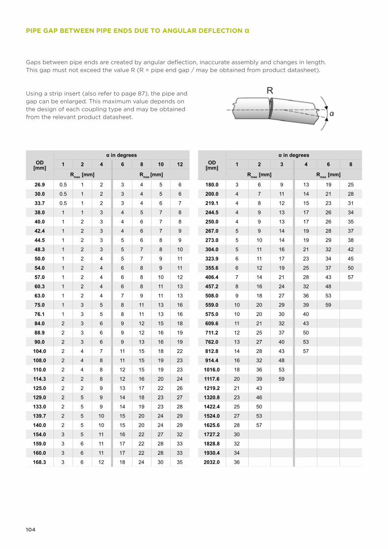
104
PIPE GAP BETWEEN PIPE ENDS DUE TO ANGULAR DEFLECTION α
OD[mm]
α in degrees
1 2 4 6 8 10 12
Rmax [mm] Rmax [mm]
26.9 0.5 1 2 3 4 5 6
30.0 0.5 1 2 3 4 5 6
33.7 0.5 1 2 3 4 6 7
38.0 1 1 3 4 5 7 8
40.0 1 2 3 4 6 7 8
42.4 1 2 3 4 6 7 9
44.5 1 2 3 5 6 8 9
48.3 1 2 3 5 7 8 10
50.0 1 2 4 5 7 9 11
54.0 1 2 4 6 8 9 11
57.0 1 2 4 6 8 10 12
60.3 1 2 4 6 8 11 13
63.0 1 2 4 7 9 11 13
75.0 1 3 5 8 11 13 16
76.1 1 3 5 8 11 13 16
84.0 2 3 6 9 12 15 18
88.9 2 3 6 9 12 16 19
90.0 2 3 6 9 13 16 19
104.0 2 4 7 11 15 18 22
108.0 2 4 8 11 15 19 23
110.0 2 4 8 12 15 19 23
114.3 2 2 8 12 16 20 24
125.0 2 2 9 13 17 22 26
129.0 2 5 9 14 18 23 27
133.0 2 5 9 14 19 23 28
139.7 2 5 10 15 20 24 29
140.0 2 5 10 15 20 24 29
154.0 3 5 11 16 22 27 32
159.0 3 6 11 17 22 28 33
160.0 3 6 11 17 22 28 33
168.3 3 6 12 18 24 30 35
OD[mm]
α in degrees
1 2 3 4 6 8
Rmax [mm] Rmax [mm]
180.0 3 6 9 13 19 25
200.0 4 7 11 14 21 28
219.1 4 8 12 15 23 31
244.5 4 9 13 17 26 34
250.0 4 9 13 17 26 35
267.0 5 9 14 19 28 37
273.0 5 10 14 19 29 38
304.0 5 11 16 21 32 42
323.9 6 11 17 23 34 45
355.6 6 12 19 25 37 50
406.4 7 14 21 28 43 57
457.2 8 16 24 32 48
508.0 9 18 27 36 53
559.0 10 20 29 39 59
575.0 10 20 30 40
609.6 11 21 32 43
711.2 12 25 37 50
762.0 13 27 40 53
812.8 14 28 43 57
914.4 16 32 48
1016.0 18 36 53
1117.6 20 39 59
1219.2 21 43
1320.8 23 46
1422.4 25 50
1524.0 27 53
1625.6 28 57
1727.2 30
1828.8 32
1930.4 34
2032.0 36
Gaps between pipe ends are created by angular deflection, inaccurate assembly and changes in length. This gap must not exceed the value R (R = pipe end gap / may be obtained from product datasheet).
Using a strip insert (also refer to page 87), the pipe and gap can be enlarged. This maximum value depends on the design of each coupling type and may be obtained from the relevant product datasheet.
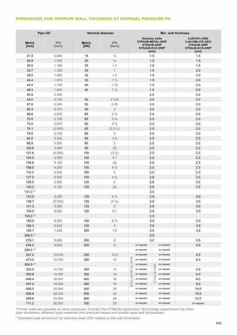
105
Pipe OD Nominal diameter Min. wall thickness
Metric[mm]
IPS[inch]
Metric[DN]
IPS[Nom]
Stainless stelleSTRAUB-METAL-GRIP
STRAUB-GRIPSTRAUB-ECO-GRIP
[mm]
CuNi10Fe (DIN)CuNi10Mn1FE (ISO)
STRAUB-GRIPSTRAUB-ECO-GRIP
[mm]21.3 0.840 15 ½ 1.5 1.526.9 1.050 20 ¾ 1.5 1.530.0 1.180 25 1.2 1.5 1.533.7 1.325 25 1 1.5 2.038.0 1.495 32 1.5 1.5 2.042.4 1.670 32 1 ¼ 1.5 2.044.5 1.750 40 1.75 1.5 2.048.3 1.900 40 1 ½ 1.5 2.050.8 2.000 2.0 2.054.0 2.125 50 2.125 2.0 2.057.0 2.245 50 2.25 2.0 2.060.3 2.375 50 2 2.0 2.066.6 2.625 65 2 ½ 2.0 2.070.0 2.756 65 2 ½ 2.0 2.073.0 2.875 65 2 ½ 2.0 2.076.1 (3.000) 65 (3 0.D.) 2.0 2.079.5 3.125 65 3 2.0 2.084.0 3.305 80 3.3 2.0 2.088.9 3.500 80 3 2.0 2.0
100.6 3.960 90 (3) 2.0 2.3101.6 (4.000) 100 (3 ½) 2.0 2.3104.0 4.095 100 4.1 2.0 2.3104.8 4.125 100 (4) 2.0 2.3108.0 4.250 100 4 ¼ 2.0 2.3114.3 4.500 100 4 2.0 2.3127.0 5.000 100 4 ½ 2.6 3.0129.0 5.080 125 5 2.6 3.0130.2 5.125 125 (5) 2.6 3.0
131.0 17 3.0133.0 5.235 125 5 ¼ 2.6 3.0139.7 (5.500) 125 (5 ½) 2.6 3.0141.3 5.565 125 5 2.6 3.0154.0 6.065 150 6.1 2.6 3.0
155.0 17 2.5159.0 6.260 150 6 ¼ 2.6 3.0168.3 6.625 150 6 2.6 3.5193.7 7.625 200 7.6 3.0 3.5
206.0 17 3.0219.1 8.625 200 8 3.0 3.5244.5 9.625 225 9 on request on request 4.5
256.0 17 on request on request
267.0 10.510 250 10.5 on request on request 4.5273.0 10.750 250 10 on request on request 5.0
306.0 17 on request on request
323.9 12.750 300 12 on request on request 5.5355.6 14.000 350 14 on request on request 6.0406.4 16.000 400 16 on request on request 8.0457.2 18.000 450 18 on request on request 9.0508.0 20.000 500 20 on request on request 10.0558.8 22.000 550 22 on request on request 10.0609.6 24.000 600 24 on request on request 12.0711.2 28.000 700 28 on request on request on request
DIMENSIONS AND MINIMUM WALL THICKNESS AT NOMINAL PRESSURE PN
Thinner walls are possible at lower pressures. Contact the STRAUB Application Technology department for other pipe diameters, different pipe materials and pressure values and smaller pipe wall thicknesses.
17 Standard pipe dimension for stainless steel (OD related to the wall thickness)
ST
RA
UB
-GR
IP
ST
RA
UB
-ME
TA
L-G
RIP
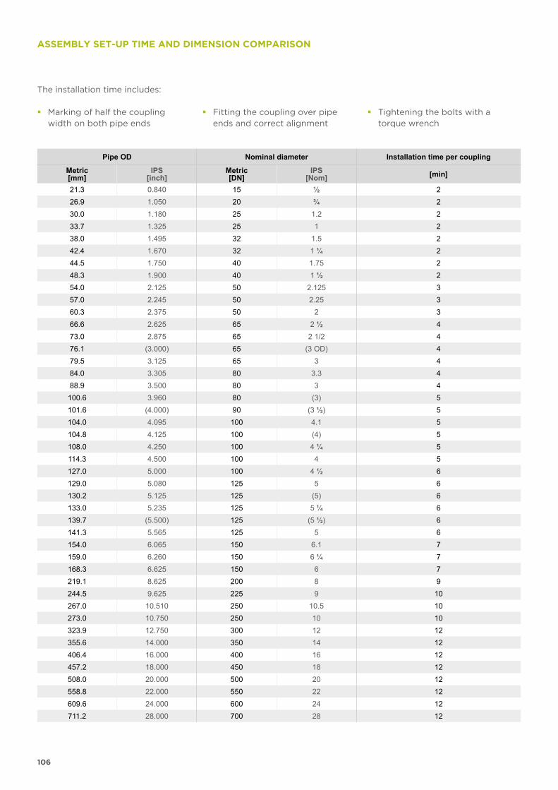
106
Pipe OD Nominal diameter Installation time per coupling
Metric[mm]
IPS[inch]
Metric[DN]
IPS[Nom] [min]
21.3 0.840 15 ½ 226.9 1.050 20 ¾ 230.0 1.180 25 1.2 233.7 1.325 25 1 238.0 1.495 32 1.5 242.4 1.670 32 1 ¼ 244.5 1.750 40 1.75 248.3 1.900 40 1 ½ 254.0 2.125 50 2.125 357.0 2.245 50 2.25 360.3 2.375 50 2 366.6 2.625 65 2 ½ 473.0 2.875 65 2 1/2 476.1 (3.000) 65 (3 OD) 479.5 3.125 65 3 484.0 3.305 80 3.3 488.9 3.500 80 3 4100.6 3.960 80 (3) 5101.6 (4.000) 90 (3 ½) 5104.0 4.095 100 4.1 5104.8 4.125 100 (4) 5108.0 4.250 100 4 ¼ 5114.3 4.500 100 4 5127.0 5.000 100 4 ½ 6129.0 5.080 125 5 6130.2 5.125 125 (5) 6133.0 5.235 125 5 ¼ 6139.7 (5.500) 125 (5 ½) 6141.3 5.565 125 5 6154.0 6.065 150 6.1 7159.0 6.260 150 6 ¼ 7168.3 6.625 150 6 7219.1 8.625 200 8 9244.5 9.625 225 9 10267.0 10.510 250 10.5 10273.0 10.750 250 10 10323.9 12.750 300 12 12355.6 14.000 350 14 12406.4 16.000 400 16 12457.2 18.000 450 18 12508.0 20.000 500 20 12558.8 22.000 550 22 12609.6 24.000 600 24 12711.2 28.000 700 28 12
The installation time includes:
� Marking of half the coupling width on both pipe ends
� Fitting the coupling over pipe ends and correct alignment
� Tightening the bolts with a torque wrench
ASSEMBLY SET-UP TIME AND DIMENSION COMPARISON
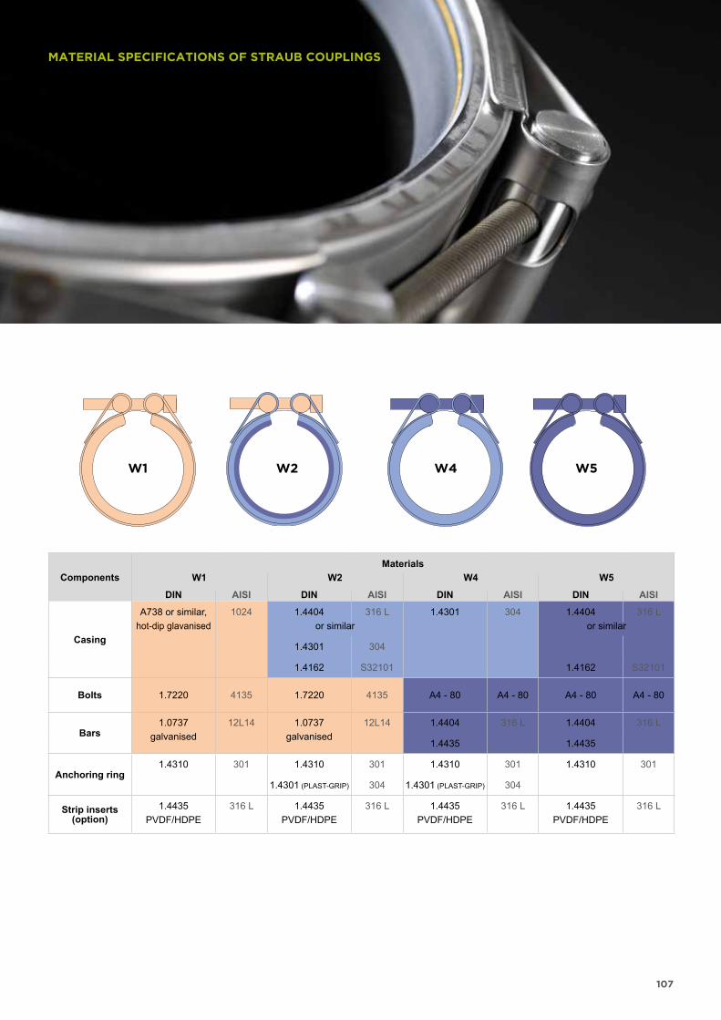
107
W1 W2 W4 W5
MATERIAL SPECIFICATIONS OF STRAUB COUPLINGS
ComponentsMaterials
W1 W2 W4 W5
DIN AISI DIN AISI DIN AISI DIN AISI
Casing
A738 or similar, 1024 1.4404 316 L 1.4301 304 1.4404 316 Lhot-dip glavanised or similar or similar
1.4301 304
1.4162 S32101 1.4162 S32101
Bolts 1.7220 4135 1.7220 4135 A4 - 80 A4 - 80 A4 - 80 A4 - 80
Bars1.0737 12L14 1.0737 12L14 1.4404 316 L 1.4404 316 L
galvanised galvanised1.4435 1.4435
Anchoring ring1.4310 301 1.4310 301 1.4310 301 1.4310 301
1.4301 (PLAST-GRIP) 304 1.4301 (PLAST-GRIP) 304
Strip inserts(option)
1.4435 316 L 1.4435 316 L 1.4435 316 L 1.4435 316 LPVDF/HDPE PVDF/HDPE PVDF/HDPE PVDF/HDPE
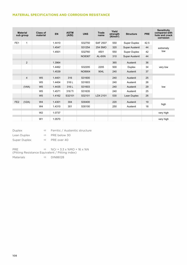
108
Material sub group
Class of material EN ASTM
(AISI) UNS Tradename
Yieldstrength(N/mm2)
Structure PRESensitivity
compared with hole and crack
corrosion
FE1 1 1.4410 S32750 SAF 2507 550 Super Duplex 42.5
extremelylow
1.4547 S31254 254 SMO 320 Super Austenit 44
1.4501 S32760 4501 550 Super Duplex 42
NO8367 AL-6XN 310 Super Austenit 44
2 1.3964 365 Austenit 36
very low1.4462 S32205 2205 500 Duplex 34
1.4539 NO8904 904L 240 Austenit 37
4 W5 1.4401 316 S31600 240 Austenit 25
low
W5 1.4404 316 L S31603 240 Austenit 26
(V4A) W5 1.4435 316 L S31603 240 Austenit 29
W5 1.4571 316 TI S31635 240 Austenit 25
W5 1.4162 S32101 S32101 LDX 2101 530 Lean Duplex 26
FE2 (V2A) W4 1.4301 304 S30400 220 Austenit 19high
W4 1.4310 301 S30100 250 Austenit 18
W2 1.0737 very high
W1 1.0570 very high
MATERIAL SPECIFICATIONS AND CORROSION RESISTANCE
Duplex Ferritic / Austenitic structure
Lean Duplex PRE below 30
Super Duplex PRE over 40
PRE %Cr + 3.3 x %MO + 16 x %N(Pitting Resistance Equivalent / Pitting index)
Materials DIN86128
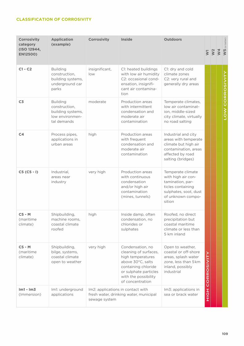
109
CLASSIFICATION OF CORROSIVITY
Corrosivity category(ISO 12944, EN12500)
Application (example)
Corrosivity Inside Outdoors
W1
W2
W4
W5
(o
r b
ett
er)
C1 - C2 Building construction, building systems,underground car parks
insignificant, low
C1: heated buildings with low air humidityC2: occasional cond-ensation, insignifi-cant air contamina-tion
C1: dry and cold climate zonesC2: very rural and generally dry areas
HIG
H C
OR
RO
SIV
ITY
LO
W C
OR
RO
SIV
ITY
C3 Building construction,building systems,low environmen-tal demands
moderate Production areas with intermittent condensation and moderate air contamination
Temperate climates, low air contaminat-ion, middle-sized city climate, virtually no road salting
C4 Process pipes, applications in urban areas
high Production areas with frequent condensation and moderate air contamination
Industrial and city areas with temperate climate but high air contamination, areas affected by road salting (bridges)
C5 (C5 - I) Industrial, areas near industry
very high Production areas with continuous condensation and/or high air contaminat ion (mines, tunnels)
Temperate climate with high air con-tamination, par-ticles containing sulphates, soot, dust of unknown compo-sition
C5 - M(maritime climate)
Shipbuilding, machine rooms, coastal climate roofed
high Inside damp, often condensation, no chlorides or sulphates
Roofed, no direct precipitation but coastal maritime climate or less than 5 km inland
C5 - M(maritime climate)
Shipbuilding, bilge, systems, coastal climate open to weather
very high Condensation, no cleaning of surfaces, high temperatures above 30°C, salts containing chloride or sulphate particles with the possibility of concentration
Open to weather, coastal or off-shore areas, splash water zone, less than 5 km inland, possibly industrial
Im1 - Im3(Immersion)
Im1: underground applications
Im2: applications in contact with fresh water, drinking water, municipal sewage system
Im3: applications in sea or brack water
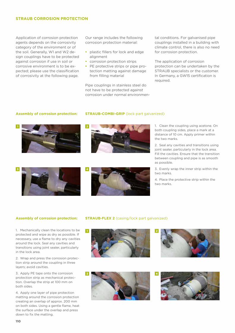
110
1
43
2
1
43
2
STRAUB CORROSION PROTECTION
Application of corrosion protection agents depends on the corrosivity category of the environment or of the soil. Generally, W1 and W2 de-sign couplings have to be protected against corrosion if use in soil or corrosive environment is to be ex-pected; please use the classification of corrosivity at the following page.
Our range includes the following corrosion protection material:
� plastic fillers for lock and edge alignment
� corrosion protection strips � PE protective strips or pipe pro-
tection matting against damage from filling material
Pipe couplings in stainless steel do not have to be protected against corrosion under normal environmen-
tal conditions. For galvanised pipe couplings installed in a building withclimate control, there is also no need for corrosion protection.
The application of corrosion protect ion can be undertaken by the STRAUB specialists or the customer. In Germany, a GW15 certification is required.
1. Clean the coupling using acetone. On
both coupling sides, place a mark at a
distance of 10 cm. Apply primer within
the two marks.
2. Seal any cavities and transitions using
joint sealer, particularly in the lock area.
Fill the cavities. Ensure that the transition
between coupling and pipe is as smooth
as possible.
3. Evenly wrap the inner strip within the
two marks.
4. Place the protective strip within the
two marks.
1. Mechanically clean the locations to be
protected and wipe as dry as possible. If
necessary, use a flame to dry any cavities
around the lock. Seal any cavities and
transitions using joint sealer, particularly
in the lock area.
2. Wrap and press the corrosion protec-
tion strip around the coupling in three
layers; avoid cavities.
3. Apply PE tape onto the corrosion
protection strip as mechanical protec-
tion. Overlap the strip at 100 mm on
both sides.
4. Apply one layer of pipe protection
matting around the corrosion protection
creating an overlap of approx. 200 mm
on both sides. Using a gentle flame, heat
the surface under the overlap and press
down to fix the matting.
Assembly of corrosion protection: STRAUB-COMBI-GRIP (lock part galvanized)
Assembly of corrosion protection: STRAUB-FLEX 2 (casing/lock part galvanized)

111
STRAUB COUPLINGS
IN SHIPBUILDING
112
STRAUB: FLEXIBILITY
IN SHIPBUILDING
Shipyards and shipbuilders in particular are
continuously faced with the challenge of laying
numerous pipes in tight, difficult-to-access
areas and are also under pressure to cut costs,
product ion and operating at the same time.
In these circumstances an optimum pipe-
connect ing system is what is called for.
Using STRAUB pipe couplings provides flexibility
and numerous cost-effective advantages.
The idea of connecting standard pipes with a flexible joining sys-tem without having to work on pipe ends was the brainchild of the company’s founder, Immanuel Straub, who, on a visit to a shipyard in Northern Germany realised the potential of introducing a flexible system that did not require work to be undertaken on pipe ends.
Flexibility, compactness, size and weights of maritime products were becoming all the more important in the building of new ships and this in turn influenced Immanuel Straub’s pipe connecting concept and led the way to a new era of maritime pipe construction.
The trademarked STRAUB-METAL-GRIP coupling has been developed and successfully launched into the maritime market. Working in con-junction with German shipbuilders and Germanischer Lloyd, the use and application of these flexible, removable and reusable couplings have been thoroughly tested and fully approved.
The German and French Navy were quick to recognise the many bene-fits of the STRAUB-METAL-GRIP. Being light, space-saving, efficient and quick to install, this innovative coupling system has been installed in their frigates, submarines and aircraft carriers. This has now expanded throughout the world.
Navy shock tests have shown that STRAUB-couplings remain sealed even in a distressed condition (i.e. following a ship collision or an un-derwater explosion).
This is due to their low weight and is in complete accordance with the principle and classification:
„SAFE TO THE NEXT PORT“
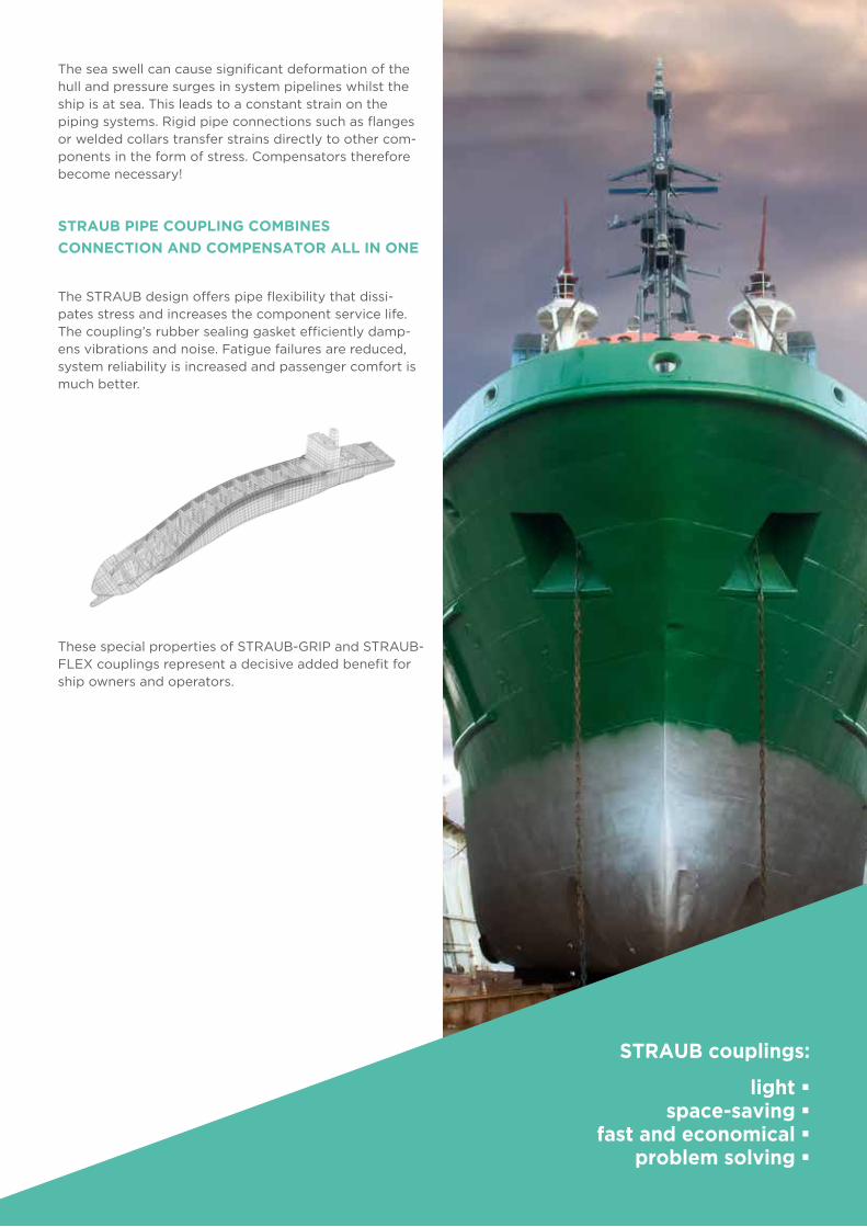
113
The sea swell can cause significant deformation of the hull and pressure surges in system pipelines whilst the ship is at sea. This leads to a constant strain on the piping systems. Rigid pipe connections such as flanges or welded collars transfer strains directly to other com-ponents in the form of stress. Compensators therefore become necessary!
STRAUB PIPE COUPLING COMBINES
CONNECTION AND COMPENSATOR ALL IN ONE
The STRAUB design offers pipe flexibility that dissi-pates stress and increases the component service life. The coupling’s rubber sealing gasket efficiently damp-ens vibrations and noise. Fatigue failures are reduced, system reliability is increased and passenger comfort is much better.
These special properties of STRAUB-GRIP and STRAUB-FLEX couplings represent a decisive added benefit for ship owners and operators.
STRAUB couplings:
light �space-saving �
fast and economical � problem solving �
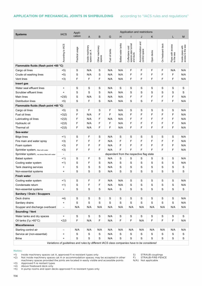
114
APPLICATION OF MECHANICAL JOINTS IN SHIPBUILDING according to “IACS rules and regulations”
Systems IACS Appli-cation
Application and restrictions
A B G H I J K L M
Acco
rdin
g to
IAC
S
Prac
tical
usa
ge
Insi
de m
achi
nery
sp
ace
cat.
A
Oth
er m
achi
nery
sp
aces
Fuel
oil
tank
s
Balla
st w
ater
tank
s
Cof
ferd
ams
void
sp
aces
pip
e tu
nnel
an
d du
cts
Acco
mm
odat
ion
and
cont
rol s
pace
Ope
n de
cks
On
freeb
oard
dec
k
Pipe
s w
ith a
cces
sto
the
sea
Insi
de p
ipes
with
ac
cess
to th
e se
a
Flammable fluids (flash point <60 °C)Cargo oil lines +5) S N/A S N/A N/A F F F F N/A N/ACrude oil washing lines +5) S N/A S N/A N/A F F F F F N/AVent lines +3) F F F N/A N/A F F F F F N/A
Insert gasWater seal effluent lines + S S S N/A S S S S S S SScrubber effluent lines + S S S N/A N/A S S S S S SMain lines +2)5) S N/A S N/A N/A F F F F F N/ADistribution lines +5) S F S N/A N/A S S F F F N/A
Flammable fluids (flash point >60 °C)Cargo oil lines +5) S F S F N/A S S S S S N/AFuel oil lines +3)2) F N/A F F N/A F F F F F N/ALubricating oil lines +2)3) F N/A F N/A N/A F F F F F N/AHydraulic oil +2)3) F N/A F F N/A F F F F F N/AThermal oil +2)3) F N/A F F N/A F F F F F N/A
Sea-waterBilge lines +1) S F S N/A S S S S S S N/AFire main and water spray +3) F F F N/A F F F F F F N/AFoam system +3) F F F N/A F F F F F F N/ASprinkler system, filled with water +3) F F F N/A F F F F F F N/ASprinkler system, not alwas filled with water - dependent from the respective flag stateBalast system +1) S F S N/A S S S S S S N/ACooling water system +1) S F S N/A S S S S S S N/ATank cleaning services + S S S N/A S S S S S S SNon-essential systems + S S S N/A S S S S S S S
Fresh waterCooling water system +1) S F F N/A N/A S S S S S N/ACondensate return +1) S F F N/A N/A S S S S S N/ANon-essential systems + S S S N/A S S S S S S S
Sanitary / Drain / ScuppersDeck drains +4) S S S S S S S S S S N/ASanitary drains + S S S S S S S S S S N/AScupper and discharge overboard – N/A N/A N/A N/A N/A N/A N/A N/A N/A N/A N/A
Sounding / VentWater tanks and dry spaces + S S S N/A S S S S S S SOil tanks (f.p.>60°C) +2)3 F N/A F N/A F F N/A F F F N/A
MiscellaneousStarting control air – N/A N/A N/A N/A N/A N/A N/A N/A N/A N/A N/AService air (non-essential) + S S S N/A S S S S S S SBrine + S S S N/A S S S S S S S
Variations of guidelines and rules by different IACS class companies have to be considered
+1) Inside machinery spaces cat A, approved fi re resistant types only+2) Not inside machinery spaces cat A or accommodation spaces; may be accepted in other machinery spaces provided the joints are located in easily visible and accessible points+3) Approved fi re resitant types+4) Above freeboard deck only+5) In pump rooms and open decks approved fi re resistant types only
S) STRAUB couplingsF) STRAUB-FIRE-FENCEN/A) Not applicable
Notes:
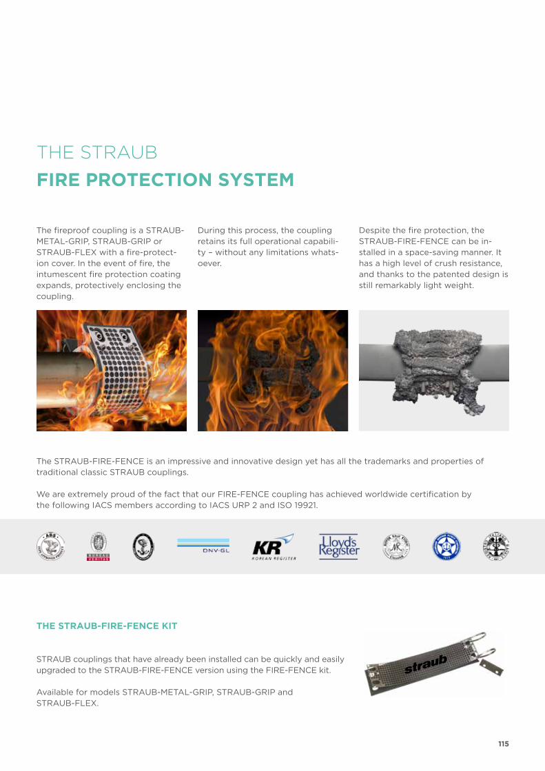
115
THE STRAUB
FIRE PROTECTION SYSTEM
The fireproof coupling is a STRAUB-METAL-GRIP, STRAUB-GRIP or STRAUB-FLEX with a fire-protect-ion cover. In the event of fire, the intumescent fire protection coating expands, pro tectively enclosing the coupling.
STRAUB couplings that have already been installed can be quickly and easily upgraded to the STRAUB-FIRE-FENCE version using the FIRE-FENCE kit.
Available for models STRAUB-METAL-GRIP, STRAUB-GRIP and STRAUB-FLEX.
During this process, the coupling retains its full operational capabili-ty – without any limitations whats-oever.
Despite the fire protection, the STRAUB-FIRE-FENCE can be in-stalled in a space-saving manner. It has a high level of crush resistance, and thanks to the patented design is still remarkably light weight.
The STRAUB-FIRE-FENCE is an impressive and innovative design yet has all the trademarks and properties of traditional classic STRAUB couplings.
We are extremely proud of the fact that our FIRE-FENCE coupling has achieved worldwide certification by the following IACS members according to IACS URP 2 and ISO 19921.
THE STRAUB-FIRE-FENCE KIT
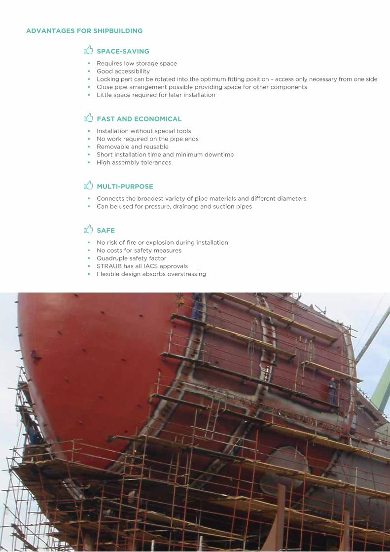
116
ADVANTAGES FOR SHIPBUILDING
SPACE-SAVING
� Requires low storage space � Good accessibility � Locking part can be rotated into the optimum fitting position – access only necessary from one side � Close pipe arrangement possible providing space for other components � Little space required for later installation
FAST AND ECONOMICAL
� Installation without special tools � No work required on the pipe ends � Removable and reusable � Short installation time and minimum downtime � High assembly tolerances
MULTI-PURPOSE
� Connects the broadest variety of pipe materials and different diameters � Can be used for pressure, drainage and suction pipes
SAFE
� No risk of fire or explosion during installation � No costs for safety measures � Quadruple safety factor � STRAUB has all IACS approvals � Flexible design absorbs overstressing
117
DAMPING
� Plenty of rubber to absorb vibrations/oscillations � Reduces pressure blows � Reduces fatigue failures � Noise reduction increases passenger comfort
TENSION-FREE
� Increases the life of fittings and systems � Compensates for axial displacement and misalignment � Coupling and compensator in one
LONG LIFE
� Corrosion resistant � Good resistance to heat and chemicals � Low torque guarantees long life
LIGHT
� Light weight � Low transport costs � Increases the payload
STRAUB connection:2.1 kg
Flanged connection:8.6 kg
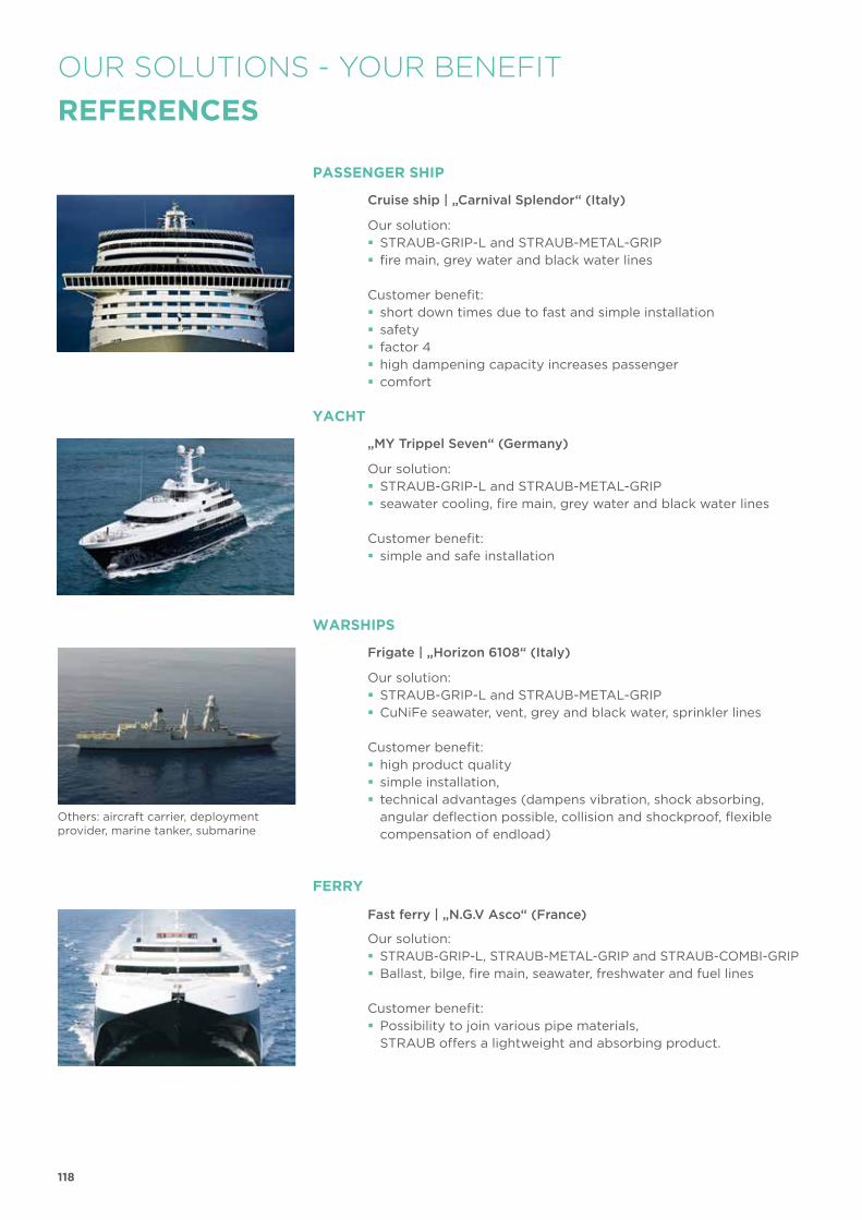
118
OUR SOLUTIONS - YOUR BENEFIT
REFERENCES
PASSENGER SHIP
Cruise ship | „Carnival Splendor“ (Italy)
Our solution: � STRAUB-GRIP-L and STRAUB-METAL-GRIP � fire main, grey water and black water lines
Customer benefit: � short down times due to fast and simple installation � safety � factor 4 � high dampening capacity increases passenger � comfort
YACHT
„MY Trippel Seven“ (Germany)
Our solution: � STRAUB-GRIP-L and STRAUB-METAL-GRIP � seawater cooling, fire main, grey water and black water lines
Customer benefit: � simple and safe installation
WARSHIPS
Frigate | „Horizon 6108“ (Italy)
Others: aircraft carrier, deployment provider, marine tanker, submarine
Our solution: � STRAUB-GRIP-L and STRAUB-METAL-GRIP � CuNiFe seawater, vent, grey and black water, sprinkler lines
Customer benefit: � high product quality � simple installation, � technical advantages (dampens vibration, shock absorbing, angular deflection possible, collision and shockproof, flexible compensation of endload)
FERRY
Fast ferry | „N.G.V Asco“ (France)
Our solution: � STRAUB-GRIP-L, STRAUB-METAL-GRIP and STRAUB-COMBI-GRIP � Ballast, bilge, fire main, seawater, freshwater and fuel lines
Customer benefit: � Possibility to join various pipe materials, STRAUB offers a lightweight and absorbing product.
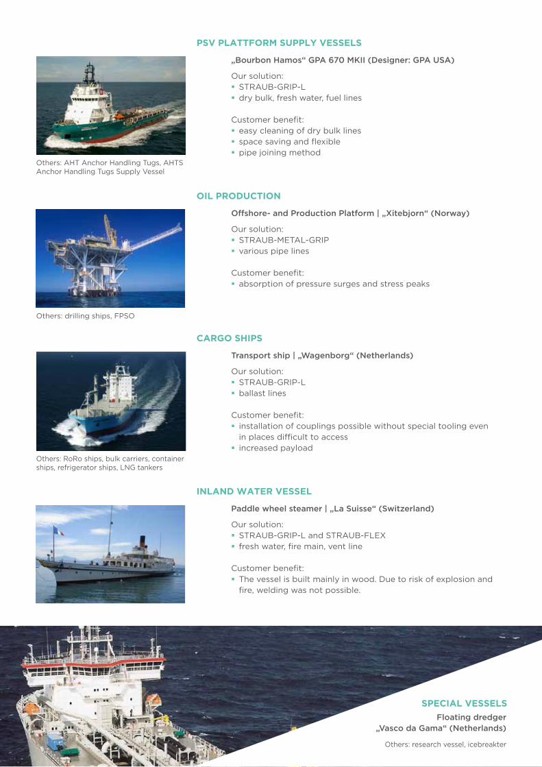
119
„Bourbon Hamos“ GPA 670 MKII (Designer: GPA USA)
PSV PLATTFORM SUPPLY VESSELS
Others: AHT Anchor Handling Tugs, AHTS Anchor Handling Tugs Supply Vessel
Others: drilling ships, FPSO
Our solution: � STRAUB-GRIP-L � dry bulk, fresh water, fuel lines
Customer benefit: � easy cleaning of dry bulk lines � space saving and flexible � pipe joining method
OIL PRODUCTION
Offshore- and Production Platform | „Xitebjorn“ (Norway)
Our solution: � STRAUB-METAL-GRIP � various pipe lines
Customer benefit: � absorption of pressure surges and stress peaks
Others: RoRo ships, bulk carriers, container ships, refrigerator ships, LNG tankers
Others: research vessel, icebreakter
CARGO SHIPS
Transport ship | „Wagenborg“ (Netherlands)
Our solution: � STRAUB-GRIP-L � ballast lines
Customer benefit: � installation of couplings possible without special tooling even in places difficult to access
� increased payload
INLAND WATER VESSEL
Paddle wheel steamer | „La Suisse“ (Switzerland)
Our solution: � STRAUB-GRIP-L and STRAUB-FLEX � fresh water, fire main, vent line
Customer benefit: � The vessel is built mainly in wood. Due to risk of explosion and fire, welding was not possible.
Floating dredger„Vasco da Gama“ (Netherlands)
SPECIAL VESSELS
120
STRAUB pipe couplings have been tested by all leading national and international classification societies and ap-proved for almost all pipe systems and in shipbuilding.
� Tightness test1.5 x PN5 min. tight
� Vibration test1 x PN3 x 106 cyclesAmplitude 0.06 / 0.5 / 1.5 mmFrequency 100 / 45 / 10Hz
� Burst pressure test4 x PN5 min. tight
� Pull-out-test1x PN + F
ax (PN as appropriate)
5 min. without leakage or other faults
� Fire-endurance test (in accordance
with ISO 19921 and 19922)
1 x PN30 min.800°Cpressure test: 2 x PN; 5 min. tight
� Vacuum test170 mbar absolute5 min. tight
� Repeated assembly test10 x assembly and dismantling1.5 x PN pressure test5 min. tight
The necessary approvals for this are based on the following tests:
� Shock testAcceleration 140 g surface shipsAcceleration 200 g submarines(for CuNiFe and C steel pipes)
� Angular deflection testAngular deflection 20°20 bar; Ø 114.3 mm5 min. tight
OUR
APPROVALS
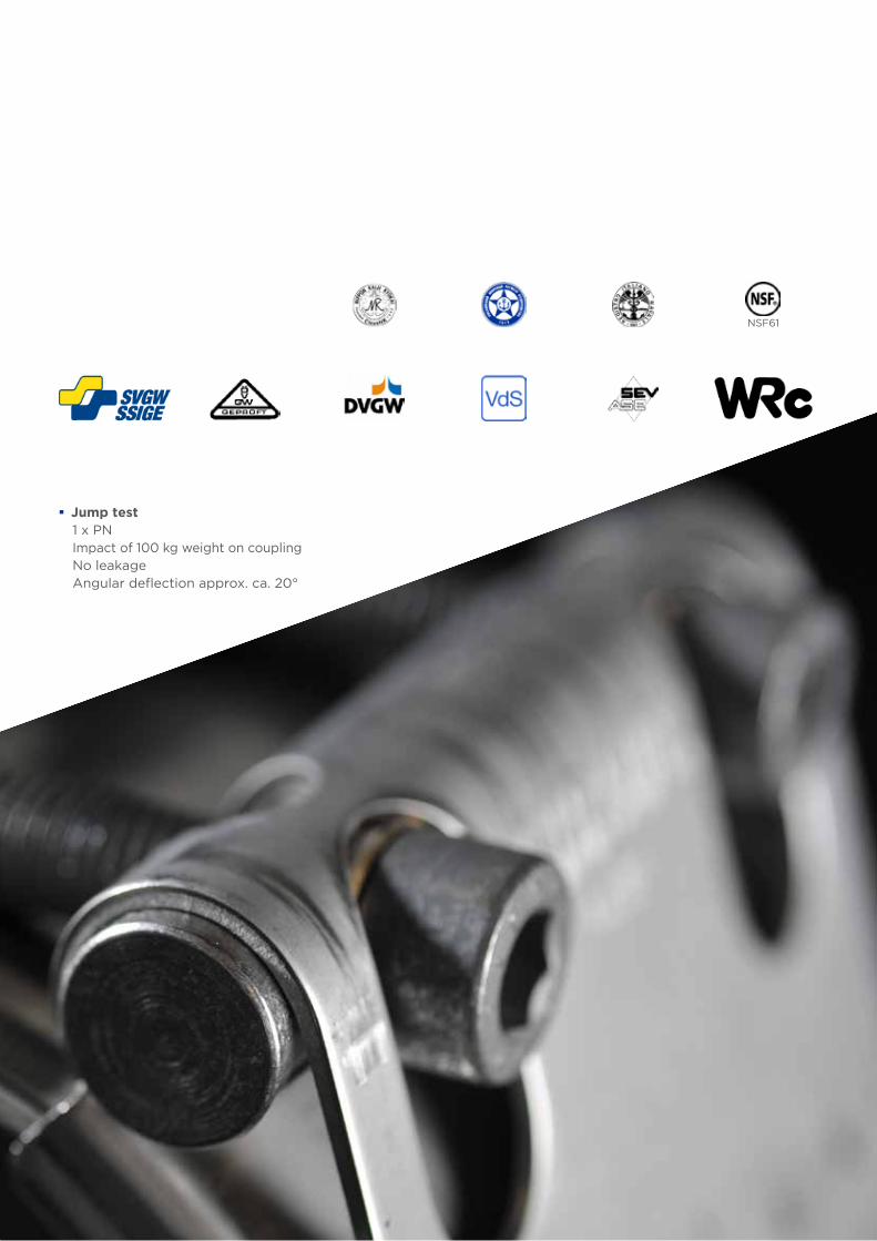
121
NSF61
� Jump test1 x PNImpact of 100 kg weight on couplingNo leakageAngular deflection approx. ca. 20°
122

123
BENEFIT FROM OUR
INTERNATIONAL CONNECTIONS
WORLDWIDE BRANCH OFFICES: WORLDWIDE WITH STRONG PARTNERS
Users all over the world in more than 60 countries place their trust in the universal STRAUB pipe coupling concept and benefit from our engineering competency and project experience. The Canadian subsidiary, an international partner network and a large number of support bases around the whole world guarantee the shortest possible delivery times and competent consultancy on site. Products are also manufactured under licence in Japan and Brazil.
Wherever you are, you can benefit from our international connections!
A list of our partners is available on the Internet at www.straub.ch
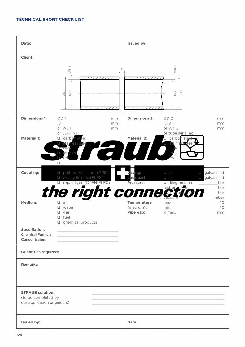
124
Date: Issued by:
Client:
RID
1
OD
1
OD
2
ID 2
WS
1
WS
2
Dimensions 1: OD 1ID 1or WS 1or SDR1 Nr.
mm mm mm
Dimensions 2: OD 2ID 2or WT 2or tube serial no
mm mm mm
Material 1: q carbon steelq stainless steelq GRPq PE / PPq PVCq
Material 2: q carbon steelq stainless steelq GRPq PE / PPq PVCq
Coupling: q pull-out restistant (GRIP)q axially flexible (FLEX)q repair type (OPEN-FLEX)
Casing:Lock part:Pressure:
q ssq ssworking pressuretest pressure(system pressure)vacuum
q galvanisedq galvanised bar bar bar mbar
Medium: q airq waterq gasq fuelq chemical products
Temperature (medium):Pipe gap:
max.min.R max.
°C °C mm
Specifiation:Chemical Formula:Concentraion:
Quantities required:
Remarks:
STRAUB solution:(to be completed by our application engineers)
Issued by: Date:
TECHNICAL SHORT CHECK LIST

125
126
SALES AND DELIVERY CONDITIONS
PURCHASE ORDERThese conditions of sale and delivery shall apply unless otherwise exception-ally agreed and confirmed in writing for an individual specific case. Alternative contractual conditions set down by the purchaser shall not be binding on us unless exceptionally agreed to and con-firmed in writing by us. All quotations set out in our offers and price lists shall be understood to be unconditional and shall only become binding on us up to the expiry of the term that we have specified for the ac-ceptance of the contract.We can not accept responsibility for any damage or loss to drawings, samples, models, etc. provided by the purchas-er with the exception of such damage or loss caused through malice or gross negligence. Any technical documentation and sam-ples produced by us shall remain our property and shall not be reproduced or be made available to a third party. These items, together with the offer shall be treated in confidence. Should an asso-ciated order not ensue we reserve the right to request the return of all relevant material.
PRICESOur prices are based on raw material costs and wage rates valid at the time. We reserve the right to take changes in costs expressly into account up to the time of delivery. Unless stated otherwise, all our prices are always quoted as being without packaging, exworks.
PAYMENT CONDITIONSa) 30 days from date of invoice without any deductionb) Pre-paymentc) against irrevocable letter of credit, confirmed by the UBS AG, Oerlikon branch, 8050 Zurich, Switzerland, pay-able 30 days from the date of confir-mation of delivery by the forwarding agency. All bank charges abroad shall be absorbed by the purchaser. Letter of credit validity: 8 weeks from date of delivery.
RETENTION OF TITLEThe supplier shall remain the property owner of the whole delivery until such times as payments have been made in full by the customer as set down in the purchase agreement. Straubshall be empowered by the customer, through the successful conclusion of the contract and at the customer’s cost, to record ownership of the goods pur-chased in official registers, ledgers or similar in cognizance of applicable local law.
DELIVERY TERMSOur information concerning delivery terms is calculated from the date of writ-ten confirmation of order or from receipt of prepayment or from confirmation of the letter of credit, alternatively start-
ing with the finalisation of the contract though not before receipt of the neces-sary documentation from the customer. Every endevour will be made to keep to the delivery terms quoted although they shall not be considered legally binding.
DELIVERYA portion of our products are delivered packed only in standard boxes. Our customers shall therefore be obliged to accept any resultant tolerance on quanti-ties. As a manufacturing undertaking we cannot accept the return or consider the exchange of over- or wrongly-ordered goods. Should a minimum quantity be absolutely necessary then this is to be noted specially on the purchase order.
TRANSFER OF USAGE AND RISKShipment of the goods shall be at the expense and risk of the purchaser. Said shipment shall be at the expense and risk of whomsoever places the order when we take care of the transport arrange-ments.
INSURANCEArrangements for any legally required public liability and material insurance in the country of destination for our products shall be the concern of the client. We explicitly cannot accept any responsibility for failure to make the nec-essary arrangements for such insurance protection.
TOOLS Through the payment of partial costs for tools, the customer shall acquire the exclusive right to the parts produced therewith although having no claim to the tools themselves; they remain the property and in possession of the supplier (see also our special conditions concerning this matter). Tool replacements and modification shall be at the customer’s expense. We shall be free to dispose of the tools as we see fit in the event of no follow-up order within a period of (5) five years.
CHECKING AND ACCEPTANCE OF THE DELIVERYThe customer shall promptly check the delivery upon receipt and notify us in writing of any shortcomings within a period of 8 (eight) days. Failure to do so shall be taken to mean that thedelivery is accepted.
GUARANTEEStraub couplings and components there-of that exhibit constructional or material faults will be replaced free-of-charge or be credited to the customer during a period of 5 years(Exceptions: STRAUB-CLAMP, STRAUB-REP-FLEX, STRAUb-PLAST-PRO and STRAUB-ECO-GRIP 2 years) reck-oned from the date of dispatch from the factory. Should a complaint concerning our products arise for the specified rea-sons within the guarantee period, they
shall be returned to our factory in 7323 Wangs/SG, Switzerland where they can be examined. Replacement of a faulty coupling or component part thereof shall only take place following the report from our testing department, which shall be final and incontestable. Our guarantee warranty shall not apply to couplings that have been installed without due observance of our assembly instructions. This shall also apply even in the face of contrary purchase conditions on the part of the customer.
LIABILITYWe shall only be held liable within the limits of the legally binding requirements for damage that is not covered by the guarantee conditions, especially for consequential damage resulting from defects concerning faulty construction or the defective function of pressed and spring parts or assembled couplings manufactured in our factory as well as from the responsibility of the produc-ers. We expressly cannot be held liable for corrosion damage on the coupling or damage in connection with compo-nents that were not manufactured in our factory.
CHANGES TO THE ORDER BY THE CUSTOMERIn the case of a contractually agreed change to the present order by the customer (quantity, dimensions, material, etc.) we shall have the right to invoice the customer for already finished items and/or raw materials or piece parts that are no longer usable for the modified order.
PATENTS / COPYRIGHTThe customer is hereby obliged to exon-erate us from any claim by a third party arising from an infringement of a patent, registered design or other protected or copyrighted matter.
LOCATION OFCONTRACTUAL FULFILMENTThe customer is hereby obliged to exon-erate us from any claim by a third party arising from an infringement of a patent, registered design or other protected or copyrighted matter.
SEAT OF JUSTICE AND APPLICABLE LAWWangs, Switzerland shall be consid-ered to be the location of contractual fulfilment for both parties for all rights and obligations arising from this legal transaction.
ACCEPTANCEUnless reported to the contrary with-in 10 (ten) days, the above sales and delivery conditions shall be taken as being accepted by the customer. In case of linguistic lacks of clarity the german version of these Sales and Delivery Con-ditions is valid.

LIABILITY DISCLAIMER
The information and data in this manual are intended to assist the user in the proper selection of STRAUB products. This
informat ion may contain inaccuracies or typographical errors. Furthermore, all the information contained in this manual list
is subject to change by STRAUB Werke AG without prior notice as a result of product re-designs, product improvements or
other reasons.
STRAUB Werke AG accepts no liability for damage arising as a result of the use of data, diagrams or application examples
in this manual.
We obtained the ISO 9001 Quality Assurance Certificate in 1995 and ISO 14001 in 2008. This confirms proven STRAUB quality and made us once again world pioneers in the area of progressive sealing pipe joints.
OUR QUALITY PRODUCTS – YOUR ADDED VALUE
ST
00
20
5_0
518
Typ
ing
err
ors
may o
ccu
r. T
ech
nic
al d
eta
ils a
re s
ub
ject
to c
han
ge.
STRAUB Werke AGStraubstrasse 13 – 7323 Wangs – SwitzerlandPhone +41 81 725 41 00 – Fax +41 81 725 41 [email protected]
www.straub.ch
Related Documents