Refill Friction Stir Spot Weld Repair of a Fatigue Crack Prepared by: Sean Long Fox Undergraduate, Metallurgical Engineering Faculty Advisors: Mr. William Arbegast Director, SDSMT Advanced Materials Processing Center Dr. Michael West REU Site Director, Department of Materials and Metallurgical Engineering Dr. Bahrat Jasthi Research Associate, SDSMT Advanced Materials Processing Center Dr. Alfred Boysen Professor, Department of Humanities Program Information: National Science Foundation Grant #: 0852057 Research Experience for Undergraduates Summer 2009 South Dakota School of Mines and Technology 501 E Saint Joseph Street Rapid City, SD 57701

Welcome message from author
This document is posted to help you gain knowledge. Please leave a comment to let me know what you think about it! Share it to your friends and learn new things together.
Transcript

Refill Friction Stir Spot Weld Repair of a Fatigue Crack
Prepared by:
Sean Long Fox
Undergraduate, Metallurgical Engineering
Faculty Advisors:
Mr. William Arbegast
Director, SDSMT Advanced Materials Processing Center
Dr. Michael West
REU Site Director, Department of Materials and Metallurgical Engineering
Dr. Bahrat Jasthi
Research Associate, SDSMT Advanced Materials Processing Center
Dr. Alfred Boysen
Professor, Department of Humanities
Program Information:
National Science Foundation
Grant #: 0852057
Research Experience for Undergraduates
Summer 2009
South Dakota School of Mines and Technology
501 E Saint Joseph Street
Rapid City, SD 57701
TABLE OF CONTENTS
Abstract ......................................................................................................................................................
Introduction ................................................................................................................
Broader Impact ..........................................................................................................
Procedure ..................................................................................................................................................
Materials and Pre-cracking Samples..………………………………………………………...
Optimization of Parameters ........................................................................................................
Surfacing and Penetration…………………………………………………………………….
Stitch Welding ..............................................................................................................................
Fatigue Crack Repairs and Testing………………………………………………………….
Results .........................................................................................................................................................
Failure Analysis..……………………………………………………………………………...
Discussion ..................................................................................................................................................
Conclusion ................................................................................................................................................
Summary .......................................................................................................................................
Future Work .................................................................................................................................
References………………………………………………………………………………………………..
Acknowledgements………………………………………………………………………
ABSTRACT
The main objective of this project is to repair a fatigue crack using Refill Friction Stir
Spot Weld Technology. This involved developing a procedure to stitch, or overlap, single spot
weld to repair fatigue cracks. A pre-cracking procedure was also developed to provide simulated
fatigue cracks on which repairs could be made. First, the welding parameters were optimized for
2024 Al T3 with a thickness of .125 inches. A .020 inch thick 2024 Al T3 peel strip is also
required to fill the volume removed from the pre-cracking procedure. The welds were then
overlapped and repairs were made. The repairs were found to have defects and the defects are
characterized to show how they reduced fatigue life. Good repairs are also characterized and
show improvement in fatigue life over cracked samples. Improved repair methods are discussed
to allow for better repairs in the future.

INTRODUCTION
Fatigue cracks can occur in any object that undergoes fatigue. In most mechanical
environments this means the part must be replaced. This is a costly and time consuming process.
If the part could be effectively repaired many resources could be saved. Standard repair
techniques cannot be used in all applications. Friction Stir Welding is a relatively new process
that gives the opportunity to make repairs that were not previously possible. In this case the
fatigue cracks were created in .125 inch thick 2024 Aluminum T3 and will be repair using the
Refill Friction Stir Spot Welding process. A RPS 100 Friction Stir Spot Welder from Riftec
(Germany) was used to perform the welds. The repair must then be analyzed in a cyclic fatigue
test to show the improved fatigue life. The expected fatigue life should fall between the fatigue
life of un-repaired samples and parent metal samples. Metallurgy and tensile testing will also be
used to characterize the repair. Failure analysis may be necessary to show errors in the repair
process and how to improve repairs. The resulting process will then be capable of being applied
to real world parts.
The objectives in this project are expressed as the following: Optimize processing
parameters for 2024 Al T3. Optimize the process for a full plunge weld with a depth of 3.3mm.
Optimize the surface to give smooth and flush welds. Optimize the overlapping “stitch welds”.
Develop pre-cracked samples. Repair pre-cracked samples. Characterize the effectiveness of the
repairs through fatigue testing and analysis.
BROADER IMPACT
In order for a part to develop a fatigue crack the part simply must undergo cyclic stress at
a level below the materials flow stress. The crack will generally form near a stress concentrator.
Sharp ninety degree angles, or areas of weakness, make good stress concentrators. Once the
crack is started it will spread to a point when the part may fail in a catastrophic manner.
Replacement parts are costly and they rely on their supply. One good example of how fatigue
cracks can be harmful would be the United States Military’s aging equipment. For instance, the
F-15 eagle is an aircraft that has been around since the early 1970’s. As this aircraft flies through
the air, the tips of the wings flutter up and down. This causes fatigue cracks to form in the wing.

A replacement wing is a costly option, but what if it could be effectively repaired? Time, money,
and resources could be saved with an effective repair procedure.
PROCEDURE
Materials and Pre-Cracking Samples
The materials that were used in this project were 2024
Aluminum in the T3 state. The 2024 Al plate was .125 inches thick
and the peel strip was also 2024 Al T3 in a .020 inch thickness. The
plates were 4 inches wide and cut into 12 inch lengths. These
samples were then dog-boned down to 3 inches in the center. Figure
1 illustrates the final specimen and the location of the pre-crack. In
order to create this simulated fatigue crack, it must first be pre-
cracked. Figure 1: Sample Config.
A Dremel tool with a cutting wheel was used to cut a slot in the center of the plate. This
slot allows the crack to begin growing in the sample. In order to actually grow the fatigue crack
we loaded the samples into a MTS 810 tensile machine. The sample was then fatigue in a
tension-tension cyclic program. Once the crack was grown to the appropriate size it was
measured and labeled. These samples were then ready to be repaired.
Optimization of Parameters
Before multiple, overlapping, welds could be made, it was necessary to optimize the
parameters for a single refill friction stir spot weld. For our purpose, we modified the rotational
speed and weld time. These parameters change the amount of heat the process input into a weld.
With 2024 Al there is copper present in the aluminum. This causes the alloy to transfer heat
rapidly. Hence the amount of heat input is high for this alloy as heat is easily transferred from the
welding site to the outlying parent metal. Improper amounts of heat yield defects such as lack of
consolidation and cold lapping. The matrix we used to visualize this process is shown below.

Figure 2: Developmental Matrix
The metallographic pictures are then inserted to show the best parameters for the weld. The
parameters we chose were 1600 rpm and a weld time of 12 seconds. Consolidation along the
sides and bottom of the weld was good. The cold lap defect was also minimal in this parameter
set. With an optimized process for a single weld, we then moved to weld surfacing and depth
penetration.
Surfacing and Penetration
Fatigue life can be reduced by any defect, including surface defects and lack of
penetration interfaces. In this case we need the surface of the weld to be flush with the plate. No
feature should extend below the surface or it will risk a reduction in fatigue life. At this point a
fatigue pre-crack slot was present in order to show how the volume loss would affect a repair.
We found that in order to have a consistent flat sure face there must be two peel strips worth of
material to consolidate the pre-crack slot. Two peel strips stacked on the plate yielded features
around the weld that were below the surface. We then found that if a single peel strip is applied
with a full plunge, followed by a second “surface” plunge with another single peel strip, the
overall weld can be milled flat to the surface. Also through metallographic examination we
found that the depth of the weld had to be adjusted to the full 3.3mm of material in order to stir
the entire thickness of the sample. The welder was adjusted and full penetration was

demonstrated at this point. Now we were ready to move on to multiple overlapping welds, also
known as stitch welding.
Stitch Welding
Now that a single spot weld had been optimized for the purpose at hand, we could then
move to overlapping spot welds. This is referred to as a stitch weld. Initially we attempted to
overlap the welds without milling each weld flat. This caused many defects by the last weld due
to an increasing thickness with each new weld. We then began milling each weld down to the
surface before moving on to the next weld. In order to study how to properly overlap the welds
we performed two tests. One involved creating various stitch welds in un-cracked samples and
putting them through a tensile test. This test was monitored by the lab’s Digital Image
Correlation cameras. The stitch welds that were tested were: a single weld, four, five, and six
welds in a single inch. The distance was measured from center to center of each weld. It was
found that four welds per inch had a far lower maximum load than the five or six welds per inch
stitch welds. The five and six welds per inch sample performed about the same in the tensile test.
The overall repair length for the pre-cracked samples was .65 inches. By applying four welds
across the crack we see that 6.25 welds per inch will be used.
Figure 3: DCI Image Showing Stress in Tension/Tension Tensile Test
From the tensile test we could tell that this would be a favorable stitch configuration for the
repair. The major strain field from digital image correlation camera image for 6 welds per inch
can be seen on the left with 5 welds per inch on the right. The ending weld present on the side
where strain is relieved. The strain field flows like water and moves outward and around the final
weld.
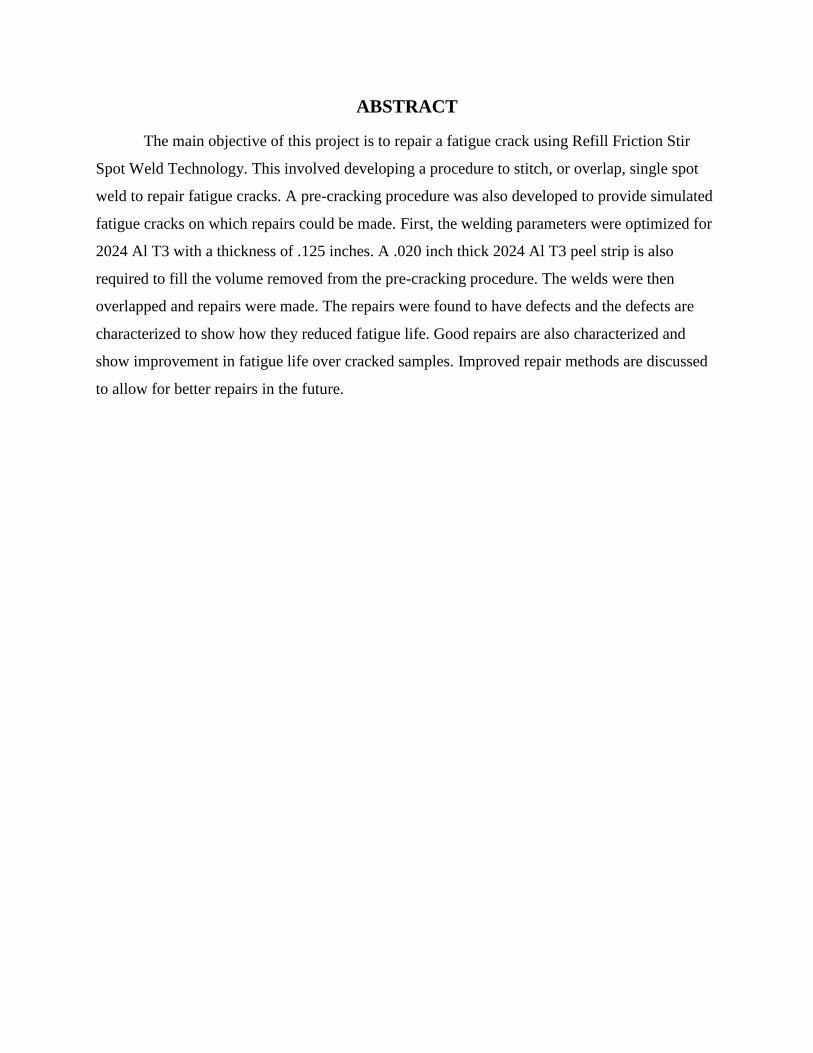
A Vicker’s hardness test was also performed on the stitch weld samples. A single spot
weld typically will have a W shape. The outside and center of the weld will generally be harder
with softer regions on either side of the center. This can be seen below in Figure 4.
Figure 4: Hardness Data Plots

In the case of the six weld per inch stitch weld we see an increase in the hardness of the
center of the welds. This explains why we see a lower strain on the final weld. The final weld is
harder and thus transfers the strain field around and to the outside of the final weld. This may
indicate how or where a fatigue crack may form. Once the stitch weld was studied we could now
make repairs.
Fatigue Crack Repair and Testing
The procedure for the final repairs was now complete. The procedure starts with cleaning
the front and back surfaces of the peel strip and cracked sample. Once clean the weld must be
measured and marked. The mark for first weld was .325 inches from the center of the crack. This
marks the center of the first weld and ensures the crack will be fully consolidated. Next, a mark
was placed every .216 inches. These marks are the centers for the next welds. Using the
parameters of 1600 rpm for 12 sec, a plunge of 3.3 mm, and a single peel strip, we made the first
welds. In all but the last two samples, a surface stamp was then used on top of the first weld.
This stamp was only to a depth of 1.2 mm and was intended to add another peel strip and ensure
a smooth top surface. The surface stamp was omitted from the process as final testing showed it
created a defect (see discussion). Once the first weld had been performed, the weld was then
milled down to a flat surface. The second weld was made on a mark .216 inches from the center
of the previous mark. This was repeated for all four welds in the stitch.
The fatigue test was then performed on the repaired samples. The testing machine was
our MTS 810 tensile machine. The samples were subjected to cyclic fatigue at multiple
percentages of flow stress. Each sample would undergo a constant maximum magnitude of a
cyclic force in tension/tension fatigue. The percentages varied as we needed to try to accurately
show the entire curve when we plotted the cycles to failure over the percentage of flow stress.
The low end of the curve is expected to “level out” so percentages were adjusted downward as
needed. The samples ran until the machine detected a failure.
RESULTS
These repairs did not show a large improvement to the fatigue life of the sample. The
following chart shows the repaired samples as series 1 (blue), and the unrepaired as series 2
(red). We can see that most of the data points show improvement, however, the low flow stress

levels show a trend of being worse than the original crack. This was not expected and a failure
analysis was perfromed on the fatigue samples.
Figure 5: Plot of Cycles to Failure vs Flow Stress %
In order to see how our repairs were failing, we used the SEM to see the fatigue crack
propegation.
Failure Analysis
The samples were not giving the expected fatigue life so an explanation was needed. In
order to show how and why these repairs failed we used our SEM to gain high maginification
pictures. The picture below shows a bad repair. The weld showing is the final weld in the stitch.
The arrows indicated mutliple points of initiation. Each is related to a defect that is reducing the
fatigue life of the repairs.
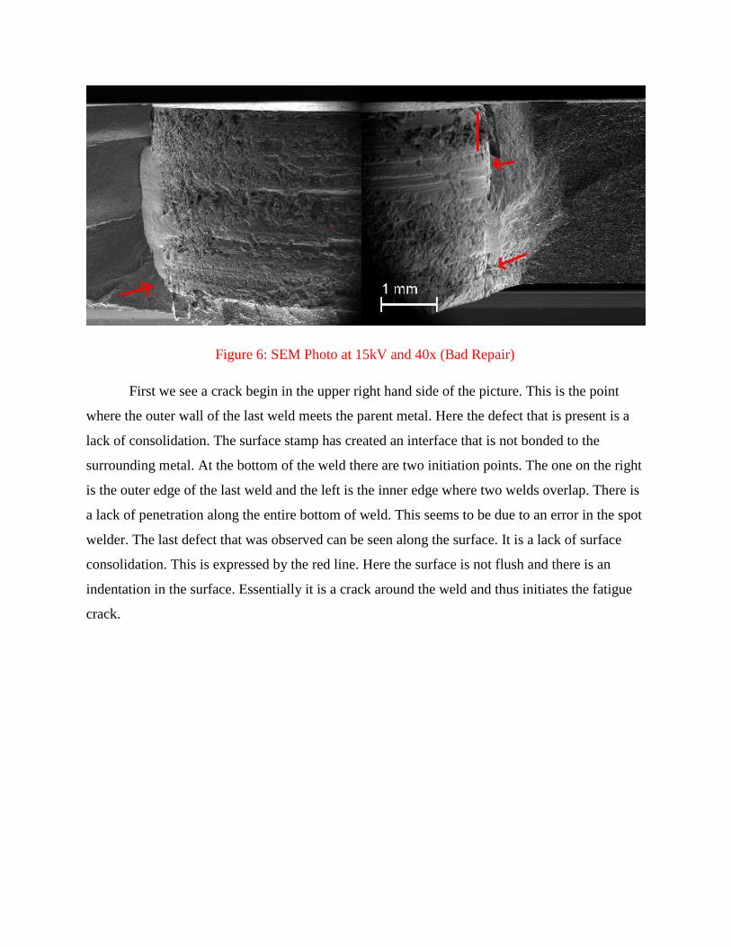
Figure 6: SEM Photo at 15kV and 40x (Bad Repair)
First we see a crack begin in the upper right hand side of the picture. This is the point
where the outer wall of the last weld meets the parent metal. Here the defect that is present is a
lack of consolidation. The surface stamp has created an interface that is not bonded to the
surrounding metal. At the bottom of the weld there are two initiation points. The one on the right
is the outer edge of the last weld and the left is the inner edge where two welds overlap. There is
a lack of penetration along the entire bottom of weld. This seems to be due to an error in the spot
welder. The last defect that was observed can be seen along the surface. It is a lack of surface
consolidation. This is expressed by the red line. Here the surface is not flush and there is an
indentation in the surface. Essentially it is a crack around the weld and thus initiates the fatigue
crack.

Figure 7: SEM Photo at 15kV and 40x (Good Repair)
We also looked at the fractured surface of a good repair. The repair is shown above with
an arrow showing the point of initiation. The dotted line indicates the orientation of the final
weld. We can see that the crack began in the final weld region as in the others. There are no
exposed defects to indicated a bad repair. The crack began along the top edge and outside edge
of the weld and continued to progress in the heat affect zone of the weld before reaching
overload and failing in the parent metal.
DISCUSSION
There are several elements that will improve repairs from the ones made in this project.
The first is to use a thinner material. Our machine is nearly at the maximum depth for a weld.
This may very well be causing the lack of penetration along the bottom of the weld. Second, the
amount of material removed in the pre-cracking process may be too great. The pre-crack volume
has to be replaced in order to ensure a good weld. A thicker peel strip could work, however, the
further apart the starting condition and the plate’s surface are the greater the chance of an
indentation on the surface. The best option would be to minimize the volume loss in the pre-

cracking process. Lastly, the way the original pre-cracks were made may have involved too
much stress and created a plastic region around the crack. When performing the final fatigue test,
the plastic region may reinforce the crack and not allow is to grow as fast. This would mean that
our pre-crack procedures may have somewhat slowed the crack from propagating past the plastic
region. The next set of samples should be pre-cracked at a lower stress level.
CONCLUSION
Summary
This project showed the potential to fix a fatigue crack. Even though the repairs that were
made were not ideal we still can learn much from them. We have shown that we can stitch weld
this material and how the process changes the hardness of each weld in the stitch. Also shown is
the ability to characterize a good and a bad weld using this process. The process must be refined
to address the defects found in the fatigue test.
Future Work
Thinner materials and refined pre-cracking procedures will be at the heart of future work.
Once the process works for simulated cracks it will need to be applied to a real world part that
has undergone real world fatigue. The overall goal is to repair fatigue cracks in an acceptable
manner so we can extend the life of various mechanical systems.
REFERENCES
Russel, SG. 2001. Static, Fatigue and Crack Growth Behavior of FSW 7075 T-6 and
2024 T-3 Aluminum Alloys. TMS Friction Stir Welding and Processing, Vol. 1, Pg. 93
Oberembt, Clark. 2008 Effects of Process and Parameters on Joint Properties of Refill
Friction Stir Spot Welded Magnesium-Aluminum Alloy
ACKNOWLEDGEMENTS
I would like to thank the NSF REU program for the opportunity to work in the AMP
Center. Dr. West, Mr. Arbegast, and Dr. Boysen for all their help over the course of this project.
I would like to thank my fellow students who worked on the project: Nick Smith, Vince Walker,
and Issac Williams.
Related Documents


![FRICTION-STIR-WELDED AND SPIN-FORMED END DOMES FOR ... · weld crown side [at top], and the weld root side [at bottom], correspond to the outer and inner mold lines of a fully-fabricated](https://static.cupdf.com/doc/110x72/5e876cb45ddcd013f07dc9a4/friction-stir-welded-and-spin-formed-end-domes-for-weld-crown-side-at-top.jpg)


![Friction Stir Welding of Shipbuilding Steel with Primer · McPerson et al. [8] compared fatigue behaviour of submerged arc and friction stir weld in DH36 concluding on am improved](https://static.cupdf.com/doc/110x72/5eb597e5216c0a5a983bbe28/friction-stir-welding-of-shipbuilding-steel-with-mcperson-et-al-8-compared-fatigue.jpg)