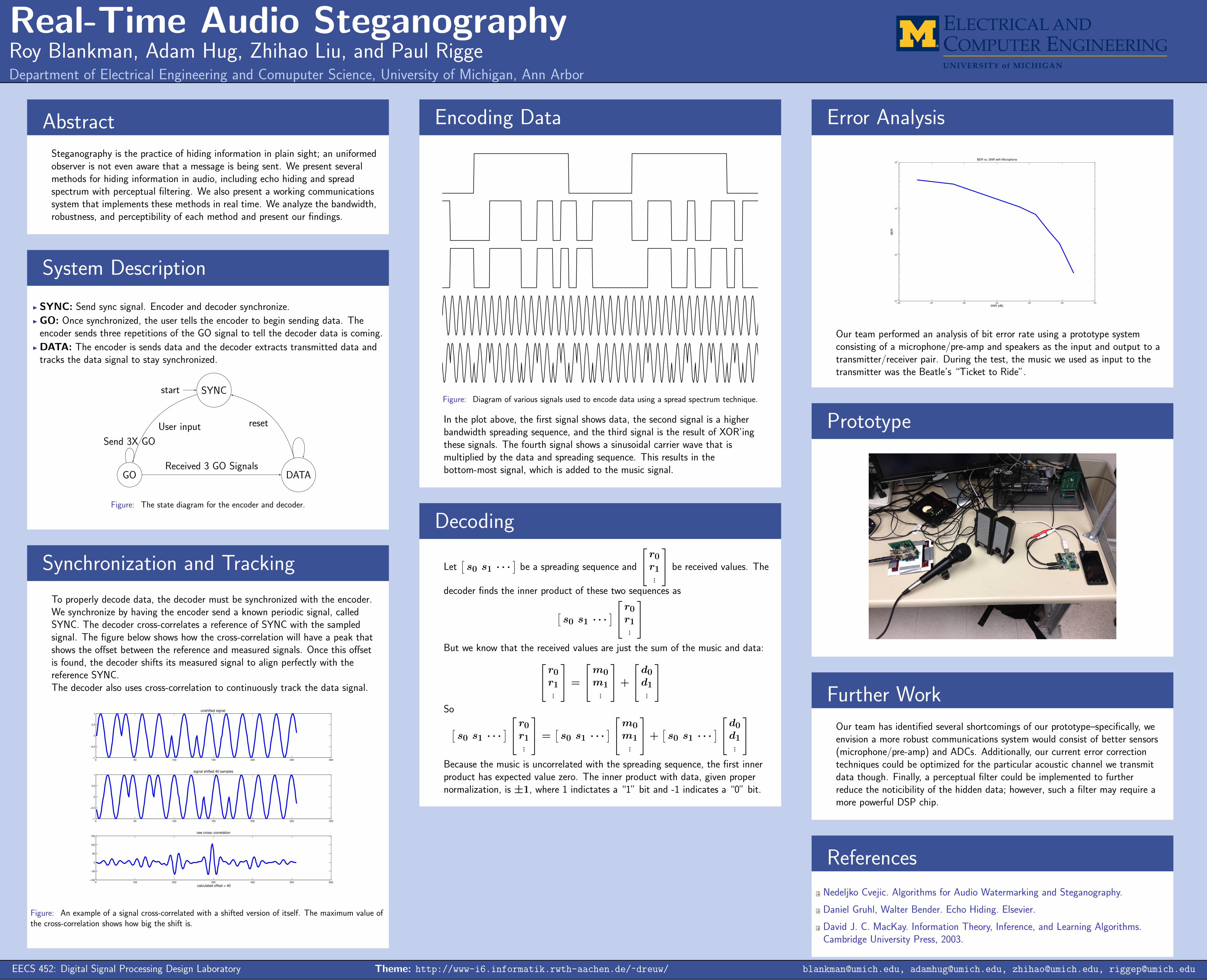
Real-Time Audio Steganography Roy Blankman, Adam Hug, Zhihao Liu, and Paul Rigge Department of Electrical Engineering and Comuputer Science, University of Michigan, Ann Arbor Abstract Steganography is the practice of hiding information in plain sight; an uniformed observer is not even aware that a message is being sent. We present several methods for hiding information in audio, including echo hiding and spread spectrum with perceptual filtering. We also present a working communications system that implements these methods in real time. We analyze the bandwidth, robustness, and perceptibility of each method and present our findings. System Description I SYNC: Send sync signal. Encoder and decoder synchronize. I GO: Once synchronized, the user tells the encoder to begin sending data. The encoder sends three repetitions of the GO signal to tell the decoder data is coming. I DATA: The encoder is sends data and the decoder extracts transmitted data and tracks the data signal to stay synchronized. SYNC start GO DATA User input Send 3X GO Received 3 GO Signals reset Figure: The state diagram for the encoder and decoder. Synchronization and Tracking To properly decode data, the decoder must be synchronized with the encoder. We synchronize by having the encoder send a known periodic signal, called SYNC. The decoder cross-correlates a reference of SYNC with the sampled signal. The figure below shows how the cross-correlation will have a peak that shows the offset between the reference and measured signals. Once this offset is found, the decoder shifts its measured signal to align perfectly with the reference SYNC. The decoder also uses cross-correlation to continuously track the data signal. 0 50 100 150 200 250 300 -1 -0.5 0 0.5 1 unshifted signal 0 50 100 150 200 250 300 -1 -0.5 0 0.5 1 signal shifted 40 samples 0 100 200 300 400 500 600 -100 -50 0 50 100 150 raw cross-correlation calculated offset = 40 Figure: An example of a signal cross-correlated with a shifted version of itself. The maximum value of the cross-correlation shows how big the shift is. Encoding Data Figure: Diagram of various signals used to encode data using a spread spectrum technique. In the plot above, the first signal shows data, the second signal is a higher bandwidth spreading sequence, and the third signal is the result of XOR’ing these signals. The fourth signal shows a sinusoidal carrier wave that is multiplied by the data and spreading sequence. This results in the bottom-most signal, which is added to the music signal. Decoding Let s 0 s 1 ··· be a spreading sequence and r 0 r 1 . . . be received values. The decoder finds the inner product of these two sequences as s 0 s 1 ··· r 0 r 1 . . . But we know that the received values are just the sum of the music and data: r 0 r 1 . . . = m 0 m 1 . . . + d 0 d 1 . . . So s 0 s 1 ··· r 0 r 1 . . . = s 0 s 1 ··· m 0 m 1 . . . + s 0 s 1 ··· d 0 d 1 . . . Because the music is uncorrelated with the spreading sequence, the first inner product has expected value zero. The inner product with data, given proper normalization, is ±1, where 1 indictates a “1” bit and -1 indicates a “0” bit. Error Analysis -45 -40 -35 -30 -25 -20 -15 10 -3 10 -2 10 -1 10 0 BER vs. SNR with Microphone SNR (dB) BER Our team performed an analysis of bit error rate using a prototype system consisting of a microphone/pre-amp and speakers as the input and output to a transmitter/receiver pair. During the test, the music we used as input to the transmitter was the Beatle’s “Ticket to Ride”. Prototype Further Work Our team has identified several shortcomings of our prototype–specifically, we envision a more robust communications system would consist of better sensors (microphone/pre-amp) and ADCs. Additionally, our current error correction techniques could be optimized for the particular acoustic channel we transmit data though. Finally, a perceptual filter could be implemented to further reduce the noticibility of the hidden data; however, such a filter may require a more powerful DSP chip. References Nedeljko Cvejic. Algorithms for Audio Watermarking and Steganography. Daniel Gruhl, Walter Bender. Echo Hiding. Elsevier. David J. C. MacKay. Information Theory, Inference, and Learning Algorithms. Cambridge University Press, 2003. EECS 452: Digital Signal Processing Design Laboratory Theme: http://www-i6.informatik.rwth-aachen.de/ ~ dreuw/ [email protected], [email protected], [email protected], [email protected]

Welcome message from author
This document is posted to help you gain knowledge. Please leave a comment to let me know what you think about it! Share it to your friends and learn new things together.
Transcript
Real-Time Audio SteganographyRoy Blankman, Adam Hug, Zhihao Liu, and Paul RiggeDepartment of Electrical Engineering and Comuputer Science, University of Michigan, Ann Arbor
Abstract
Steganography is the practice of hiding information in plain sight; an uniformedobserver is not even aware that a message is being sent. We present severalmethods for hiding information in audio, including echo hiding and spreadspectrum with perceptual filtering. We also present a working communicationssystem that implements these methods in real time. We analyze the bandwidth,robustness, and perceptibility of each method and present our findings.
System Description
I SYNC: Send sync signal. Encoder and decoder synchronize.
I GO: Once synchronized, the user tells the encoder to begin sending data. Theencoder sends three repetitions of the GO signal to tell the decoder data is coming.
I DATA: The encoder is sends data and the decoder extracts transmitted data andtracks the data signal to stay synchronized.
SYNCstart
GO DATA
User input
Send 3X GO
Received 3 GO Signals
reset
Figure: The state diagram for the encoder and decoder.
Synchronization and Tracking
To properly decode data, the decoder must be synchronized with the encoder.We synchronize by having the encoder send a known periodic signal, calledSYNC. The decoder cross-correlates a reference of SYNC with the sampledsignal. The figure below shows how the cross-correlation will have a peak thatshows the offset between the reference and measured signals. Once this offsetis found, the decoder shifts its measured signal to align perfectly with thereference SYNC.The decoder also uses cross-correlation to continuously track the data signal.
0 50 100 150 200 250 300−1
−0.5
0
0.5
1unshifted signal
0 50 100 150 200 250 300−1
−0.5
0
0.5
1
signal shifted 40 samples
0 100 200 300 400 500 600−100
−50
0
50
100
150
raw cross−correlation
calculated offset = 40
Figure: An example of a signal cross-correlated with a shifted version of itself. The maximum value ofthe cross-correlation shows how big the shift is.
Encoding Data
Data
Spread
Data+Spread
Carrier
Final
Figure: Diagram of various signals used to encode data using a spread spectrum technique.
In the plot above, the first signal shows data, the second signal is a higherbandwidth spreading sequence, and the third signal is the result of XOR’ingthese signals. The fourth signal shows a sinusoidal carrier wave that ismultiplied by the data and spreading sequence. This results in thebottom-most signal, which is added to the music signal.
Decoding
Let[s0 s1 · · ·
]be a spreading sequence and
r0r1...
be received values. The
decoder finds the inner product of these two sequences as
[s0 s1 · · ·
] r0r1...
But we know that the received values are just the sum of the music and data: r0
r1...
=
m0m1
...
+
d0d1...
So[
s0 s1 · · ·] r0
r1...
=[s0 s1 · · ·
] m0m1
...
+[s0 s1 · · ·
] d0d1...
Because the music is uncorrelated with the spreading sequence, the first innerproduct has expected value zero. The inner product with data, given propernormalization, is ±1, where 1 indictates a “1” bit and -1 indicates a “0” bit.
Error Analysis
−45 −40 −35 −30 −25 −20 −1510
−3
10−2
10−1
100
BER vs. SNR with Microphone
SNR (dB)
BE
R
Our team performed an analysis of bit error rate using a prototype systemconsisting of a microphone/pre-amp and speakers as the input and output to atransmitter/receiver pair. During the test, the music we used as input to thetransmitter was the Beatle’s “Ticket to Ride”.
Prototype
Further Work
Our team has identified several shortcomings of our prototype–specifically, weenvision a more robust communications system would consist of better sensors(microphone/pre-amp) and ADCs. Additionally, our current error correctiontechniques could be optimized for the particular acoustic channel we transmitdata though. Finally, a perceptual filter could be implemented to furtherreduce the noticibility of the hidden data; however, such a filter may require amore powerful DSP chip.
References
Nedeljko Cvejic. Algorithms for Audio Watermarking and Steganography.
Daniel Gruhl, Walter Bender. Echo Hiding. Elsevier.
David J. C. MacKay. Information Theory, Inference, and Learning Algorithms.Cambridge University Press, 2003.
EECS 452: Digital Signal Processing Design Laboratory Theme: http://www-i6.informatik.rwth-aachen.de/~dreuw/ [email protected], [email protected], [email protected], [email protected]
Related Documents

![A Survey of Steganography and Steganalysis Technique in ...fortega/spring17/df... · In video steganography, same method may be used to embed a message [17, 23]. Audio steganography](https://static.cupdf.com/doc/110x72/5eb527d80cc8a7284b3ec0b3/a-survey-of-steganography-and-steganalysis-technique-in-fortegaspring17df.jpg)