Radiocommunication Service Monitor CMS Radio testers for service, production and development • Radio tester family comprising three models to cover all measurement requirements • Suitable for every type of radio equipment • Transmitter, receiver and duplex measurements on mobile radios, base stations and RF modules • Analog and digital signalling • Large high-contrast LCD screen • Simultaneous display of settings and results • Manual and automatic measure- ments • Tracking generator • Spectrum monitor • Stationary and mobile use • Cable fault finder Digital pictures are not available ((WF 41 408)) 0,4 to 1000 MHz

Welcome message from author
This document is posted to help you gain knowledge. Please leave a comment to let me know what you think about it! Share it to your friends and learn new things together.
Transcript
Radiocommunication Service Monitor CMSRadio testers for service, production and development
• Radio tester family comprising three models to cover all measurement requirements
• Suitable for every type of radio equipment
• Transmitter, receiver and duplex measurements on mobile radios, base stations and RF modules
• Analog and digital signalling• Large high-contrast LCD screen• Simultaneous display of settings
and results
• Manual and automatic measure-ments
• Tracking generator• Spectrum monitor• Stationary and mobile use• Cable fault finder
Digital pictures are not available
((WF 41 408))
0,4 to 1000 MHz
Cms_23.fm Seite 1 Freitag, 27. April 2001 3:27 15
2 Radiocommunication Service Monitor CMS
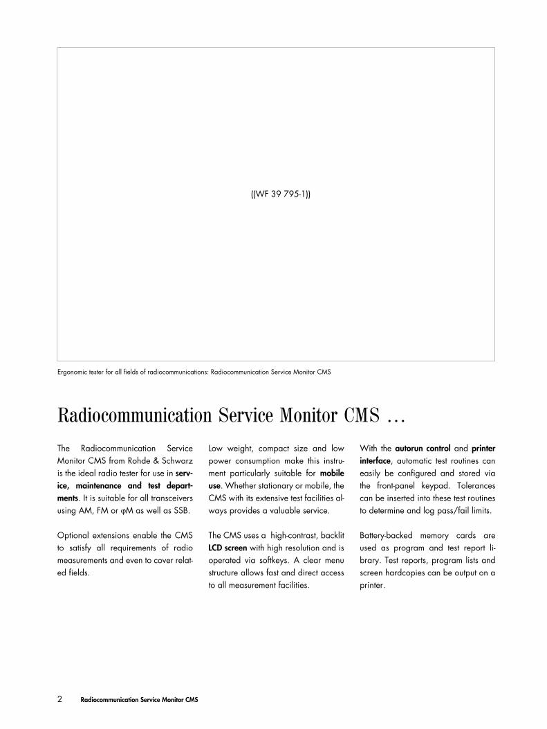
The Radiocommunication ServiceMonitor CMS from Rohde & Schwarzis the ideal radio tester for use in serv-ice, maintenance and test depart-ments. It is suitable for all transceiversusing AM, FM or ϕM as well as SSB.
Optional extensions enable the CMSto satisfy all requirements of radiomeasurements and even to cover relat-ed fields.
Low weight, compact size and lowpower consumption make this instru-ment particularly suitable for mobileuse. Whether stationary or mobile, theCMS with its extensive test facilities al-ways provides a valuable service.
The CMS uses a high-contrast, backlitLCD screen with high resolution and isoperated via softkeys. A clear menustructure allows fast and direct accessto all measurement facilities.
With the autorun control and printerinterface, automatic test routines caneasily be configured and stored viathe front-panel keypad. Tolerancescan be inserted into these test routinesto determine and log pass/fail limits.
Battery-backed memory cards areused as program and test report li-brary. Test reports, program lists andscreen hardcopies can be output on aprinter.
((WF 39 795-1))
Radiocommunication Service Monitor CMS
Ergonomic tester for all fields of radiocommunications: Radiocommunication Service Monitor CMS
Cms_23.fm Seite 2 Freitag, 27. April 2001 3:27 15
Radiocommunication Service Monitor CMS 3
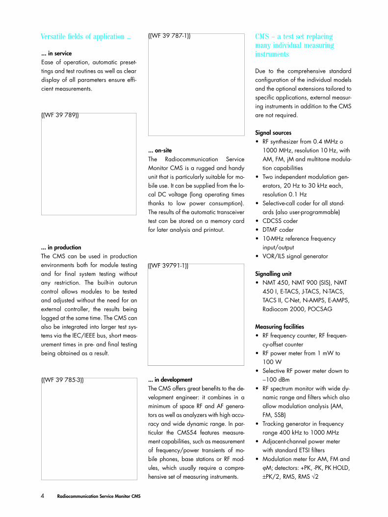
CMS54 – the high-end tester for demanding requirements
• Transmitter and receiver testing with enhanced capabili-ties of CMS50 (see specifications)
• RF spectrum monitor with zero-span to full-span display• Extremely sensitive RF frequency counter• Transient recorder for
– frequency versus time– power versus time
• Fully automatic testing
Additional equipment:• Full-span tracking generator from 0.4 MHz to 1000 MHz• Adjacent-channel power meter with standard ETSI filters• Duplex modulation meter• Automatic harmonic measurements• Cable fault finder
CMS57 – the specialist for avionics
• Transmitter and receiver testing with enhanced capabili-ties of CMS50 (see specifications)
• RF spectrum monitor with zero-span to full-span display• Extremely sensitive RF frequency counter• Transient recorder for
– frequency versus time– power versus time
• Fully automatic testing
Additional equipment:• VOR/ILS signal generator
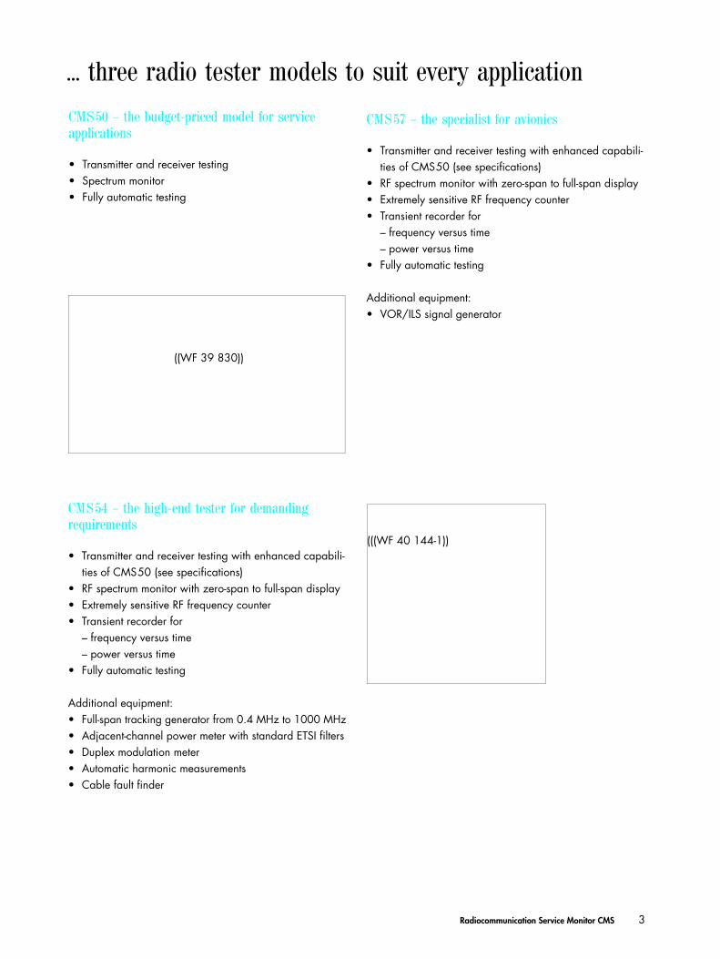
CMS50 – the budget-priced model for service applications
• Transmitter and receiver testing• Spectrum monitor• Fully automatic testing
(((WF 40 144-1))
... three radio tester models to suit every application
((WF 39 830))
Cms_23.fm Seite 3 Freitag, 27. April 2001 3:27 15
4 Radiocommunication Service Monitor CMS
CMS – a test set replacing many individual measuring instruments
Due to the comprehensive standardconfiguration of the individual modelsand the optional extensions tailored tospecific applications, external measur-ing instruments in addition to the CMSare not required.
Signal sources• RF synthesizer from 0.4 tMHz o
1000 MHz, resolution 10 Hz, with AM, FM, jM and multitone modula-tion capabilities
• Two independent modulation gen-erators, 20 Hz to 30 kHz each, resolution 0.1 Hz
• Selective-call coder for all stand-ards (also user-programmable)
• CDCSS coder• DTMF coder• 10-MHz reference frequency
input/output• VOR/ILS signal generator
Signalling unit• NMT 450, NMT 900 (SIS), NMT
450 I, E-TACS, J-TACS, N-TACS, TACS II, C-Net, N-AMPS, E-AMPS, Radiocom 2000, POCSAG
Measuring facilities• RF frequency counter, RF frequen-
cy-offset counter• RF power meter from 1 mW to
100 W• Selective RF power meter down to
−100 dBm• RF spectrum monitor with wide dy-
namic range and filters which also allow modulation analysis (AM, FM, SSB)
• Tracking generator in frequency range 400 kHz to 1000 MHz
• Adjacent-channel power meter with standard ETSI filters
• Modulation meter for AM, FM and ϕM; detectors: +PK, -PK, PK HOLD, ±PK/2, RMS, RMS √2
((WF 39 789))
... in service
Versatile fields of application ... ((WF 39 787-1))
... on-siteThe Radiocommunication ServiceMonitor CMS is a rugged and handyunit that is particularly suitable for mo-bile use. It can be supplied from the lo-cal DC voltage (long operating timesthanks to low power consumption).The results of the automatic transceivertest can be stored on a memory cardfor later analysis and printout.
Ease of operation, automatic preset-tings and test routines as well as cleardisplay of all parameters ensure effi-cient measurements.
((WF 39791-1))
((WF 39 785-3)) ... in developmentThe CMS offers great benefits to the de-velopment engineer: it combines in aminimum of space RF and AF genera-tors as well as analyzers with high accu-racy and wide dynamic range. In par-ticular the CMS54 features measure-ment capabilities, such as measurementof frequency/power transients of mo-bile phones, base stations or RF mod-ules, which usually require a compre-hensive set of measuring instruments.
... in productionThe CMS can be used in productionenvironments both for module testingand for final system testing withoutany restriction. The built-in autoruncontrol allows modules to be testedand adjusted without the need for anexternal controller, the results beinglogged at the same time. The CMS canalso be integrated into larger test sys-tems via the IEC/IEEE bus, short meas-urement times in pre- and final testingbeing obtained as a result.
Cms_23.fm Seite 4 Freitag, 27. April 2001 3:27 15
Radiocommunication Service Monitor CMS 5
• Duplex modulation meter for du-plex spacings of any size
• AF voltmeter with peak and true RMS weighting
• SINAD meter with variable test fre-quency
• S/N meter• Distortion meter with variable test
frequency• AF frequency counter with period
and gate-time counting• Selective-call decoder for all stand-
ards (also user-programmable)• DTMF decoder• Oscilloscope• DC ammeter/voltmeter• Transient recorder for analysis of
power and frequency transients• SSB menus• Harmonic measurements• Cable fault finder
Filters• CCITT or C-message filter for
weighting to relevant standards• Continuously tunable bandpass fil-
ter from 50 Hz to 5 kHz with high
skirt selectivity for selective modu-lation and AF measurements
• Continuously tunable notch filter from 100 Hz to 5 kHz for signal suppression
• Highpass and lowpass filters for band limiting and measurement of subaudio tones
Other facilities• Second RF input with high sensitivi-
ty for off-air measurements, can be used independently for module testing
• Built-in 600-Ω AF transformers for modulation generator and AF volt-meter
• Connector for battery (11V to 32 V)• 13-dBm RF output for off-air meas-
urements• Memory for storing complete in-
strument setups• Carrier bag
Automatic tests
Automatic test routines are indispensa-ble for high throughput and reproduc-ible results in service and production:in the learn mode, the Radiocommuni-cation Service Monitor CMS stores allmanual settings and measurementsand produces from them ready-to-startautomatic test routines.
The user need not have any program-ming knowledge or learn equip-ment-specific command sets.
Tolerances, comments and conditions(loops, jumps, queries and controlcommands) can additionally be insert-ed into these test routines. Programscan also be activated directly from thememory card.
The test report format may be us-er-specified and can be clearly struc-tured by transferring control charac-ters to the printer, such as blank line,paragraph and bold-face.
((WF 39834))
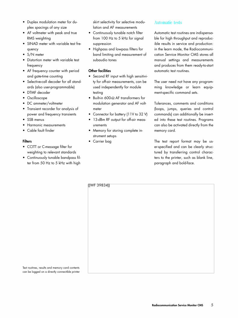
Test routines, results and memory card contents can be logged on a directly connectible printer
Cms_23.fm Seite 5 Freitag, 27. April 2001 3:27 15
6 Radiocommunication Service Monitor CMS
CMS user prompting – all settings and test parameters at a glance
RF measurements, evaluation of demodulated signals and setting of modulationgenerators
Contents, duration and frequency de-viation of selective call signals
Zoom function for alignment
The user interface, which shows all im-portant measurements and allows en-try of the necessary parameters, is op-timized for each application.
Erroneous settings immediately resultin a prompt for clarification from theuser.
Submenus can be called up for settingor evaluating specific individual pa-rameters.
Using the insertion units of the NASfamily, VSWR, forward and reflectedpower can be indicated
150-Hz filter allowing direct modulation analysis for AM, FM and SSB
Transmitter test
Spectrum monitor/Tracking generator
Cms_23.fm Seite 6 Freitag, 27. April 2001 3:27 15
Radiocommunication Service Monitor CMS 7
Settings made are shown in the mainmenu so that erroneous measurementsdue to unknown background settingsare impossible.
The user interface may be selected inEnglish, French, German, Italian,Spanish or Swedish.
Instrument settings and frequenciescan be saved in an internal nonvola-tile memory and recalled as required.
Channel numbers and duplex spacingcan be defined and used instead offrequencies
External modulation can be used e.g.for modulating several tones or datasignals for various systems
Semi-automatic search routines forsquelch level, receiver bandwidth andsensitivity perform elaborate measure-ments within a few seconds
Transmitter and receiver parameters at a glance; efficient measurements on du-plex radio equipment and modules
Generator settings, evaluation of receiver AF and carrier modulation setting
Duplex test
Receiver test
Cms_23.fm Seite 7 Freitag, 27. April 2001 3:27 15
8 Radiocommunication Service Monitor CMS
POCSAG (Post Office Code Standard-ization Advisory Group) signalling al-lows extremely simple addressing ofand test calls to all paging systems cur-rently on the market and operating ac-cording to this standard, e.g. Cityruf,Euromessage, tone call as well as nu-meric and alphanumeric pagers.
Signalling
The CMS features built-in signallingunits combining signalling measure-ments and receiver/transmitter tests onmobile stations as well as, to a certainextent, on base stations.
The signalling units support all mainradio networks including their coun-try-specific versions.
No external equipment is required fortesting. All signalling routines are per-manently available (no loading or re-loading of software is required).
The following standards can be simulated:• Selective call to all international
standards• DTMF coding and decoding• POCSAG/Cityruf/Euromessage• CDCSS (Continuous Digital Cod-
ed Squelch System)
The following signalling routines areavailable for cellular networks:• C-Net• NMT 450 (SIS), NMT 450 I• NMT 900 (SIS)• AMPS, E-AMPS• TACS, E-TACS, J-TACS, TACS II• Radiocom 2000
Cms_23.fm Seite 8 Freitag, 27. April 2001 3:27 15
Radiocommunication Service Monitor CMS 9
Cellular networks
NMT is operated in several countrieswith different frequencies, duplex andchannel spacings. The CMS takes ac-count of this fact by allowing free se-lection and country-specific definitionof each parameter. This basic settingis retained for further measurementsafter the instrument is switched off andon. The signalling test combines ana-log RF and AF measurements with dig-ital signalling which can be recalledvery easily and is adaptable in practi-cally all network parameters.
In addition to NMT, Radiocom 2000signalling is used in France. The CMSsupports private and public telephonenetworks as well as mixed types of net-works and channel change. Transmit-ter frequency, duplex spacing andchannel spacing can be freely definedfor special phones.
The test configuration for TACS/AMPSphones is similar to other standards,but the signalling is completely differ-ent. However, the user need not referto the specifications, but is convenient-ly menu-guided through the mobilephone test as with all other tests.
Cms_23.fm Seite 9 Freitag, 27. April 2001 3:27 15

Unit in original size
All functions are clearly displayed; 16softkeys allow direct access to individ-ual parameters.
The large, backlit LCD screen providesclear and simultaneous readout of alltest results, entries and functions.
Hardcopy of screen display, entry oftolerance and reference values aremade at a keystroke.
Cms_23.fm Seite 10 Freitag, 27. April 2001 3:27 15

Settings can be varied in selectablesteps using the spinwheel.
Programs, instrument settings and testresults can be stored on memorycards.
Additional inputs and outputs allow in-dependent and versatile use of signalsources and test facilities.
Cms_23.fm Seite 11 Freitag, 27. April 2001 3:27 15
12 Radiocommunication Service Monitor CMS
• Storage of spectrum displays and demodulation of displayed spec-tral lines (FREEZE & LISTEN)
• Quick mode for fast alignment of RF components
• Built-in tracking generator with se-lectable level and frequency offset; for measurements on filters, mod-ules and antenna systems
• Cable fault finder
Transient frequency and power measurements
Measurement of power levels uponswitching a transmitter on and off or ofpower ramps (data transmission sys-tem)
Display of frequency transients whenswitching transceivers on/off or whenchanging channel
Combined display of power and fre-quency transients
For all fields of radiocommunications:• Base-station testing and monitoring• Development of RF modules for
any application such as– radio remote control– cordless telephones– door-closing systems
• Production and installation of sys-tems with high or low transmitter power, such as– high-power transmitters– radio telephones, handies
• Duplex modulation meter with any frequency offset
• Direct measurement of transmitter harmonic suppression
Full-span spectrum monitor• Full-span spectrum display from
10 MHz to 1000 MHz• Display range 80 dB• Analysis bandwidths from 150 Hz
(modulation spectra AM/FM/SSB) to 3 MHz
• Sensitivity down to −110 dBm• Markers for synthesizer-accurate
frequency and selective level meas-urements
• Reference marker
CMS54 – the radio tester for the high-end service
Cms_23.fm Seite 12 Freitag, 27. April 2001 3:27 15
Radiocommunication Service Monitor CMS 13
Additional data of CMS54
Specifications of Base Unit (pages 18 and 19) are fully applicable.
RF spectrum monitor (also for CMS57)Frequency range 1 MHz to 1000 MHzSpan 0 (zero span) to 50 MHz; full span for
frequency range 10MHz to 1000 MHzReference level +47dB to -47 dBm (input 1)Sensitivity <-110 dBm (for resolution filter ≤6 kHz
and reference level ≤−37 dBm at in-put 2, f ≥10 MHz)
Inherent spurious responses <-50 dBc (for reference level >10 dBm and f >50 MHz)
Display dynamic range >65 dB (for reference level >-7 dBm at input 1)
Scaling 2/5/10 dB/divDisplay range ≤80 dBResolution filter (3-dB bandwidth) 150 Hz (for modulation analysis),
6/16/50/300 kHz/1/3 MHz (for full span), coupled to span
Error <3 dB + resolutionResolution 0.4 dB
Transient recorder (also for CMS57)Measurement of power and frequency as a function of time with graphical display and selectable zoom
Time scale 50 µs/div to 1 s/div, max. recording time 40 s
Frequency transientsRF measurement range 1 MHz to 1000 MHzFM deviation measurement range 0 to ±100 kHzScaling 0.5 kHz to 50 kHz/divTriggering internal, automatic (frequency chang-
es >8 kHz)Power transientsRF measurement range 1 MHz to 1000 MHzDisplay dynamic range 60 dB (for 47 dBm at input 1)Scaling 2/5/10/20 dB/divTriggering internal, automatic (power 10%)
Adjacent-channel power measurements (with CMS-B9 also for CMS57)Filter conform to ETSI recommendation
Channel spacings 10/12.5/20/25 kHz and freely se-lectable up to 1 MHz
Dynamic range (CW, FM)25 kHz 70 dB20 kHz 69 dB12.5 kHz 68 dB10 kHz 66 dB
Harmonic measurements (with CMS-B9 also for CMS57)Display of 1st to 4th harmonicMax. harmonic frequency 1000 MHzDynamic range >60 dB
>90 dB in frequency range 26.965 MHz to 27.405 MHz (CB radio)
RF frequency counter (also for CMS57)Frequency range 0.5 MHz to 1000 MHz
(usable from 100 kHz, IF narrow)Input level range (CW, FM) Input 1 0 to +47 dBm Input 2 -40 dBm to +7 dBm
Transmitter measurement, 2nd RF input (also for CMS57)Additional internal switch-selectable 0/24-dB attenuator pad for measure-ments with higher levels at input 2
Adjacent-channel power measurementAdjacent-channel power can be meas-ured directly without external filters. Thefilters required to ETSI recommendationsare integrated in the CMS.
Harmonic measurementsHarmonics in the range up to 1 GHzare measured at a keystroke and dis-played in digital and analog form.
Cms_23.fm Seite 13 Freitag, 27. April 2001 3:27 15
14 Radiocommunication Service Monitor CMS
CMS57 – the avionics specialist
Fine variation of the DDM value in steps of 0.001 DDM for ILS and of phase in steps of 0.01° for VOR ensure accurate adjust-ment of onboard monitor
The AF oscillo-scope can be used in all operating modes, allowing for instance a si-multaneous display of the signal de-modulated by the device under test
A menu is also available for the generation of marker beacons
The CMS57 features the same charac-teristics and optional extension facili-ties as the CMS52.
The VOR/ILS test signals are availableas RF and AF signals at different out-puts.
The RF is not limited to the defined re-ceiving ranges, but can be user-select-ed for versatile applications (e.g. IF module testing). Since the VOR/ILSAF signal is provided separately, itcan be fed into demodulators, filtersor rectifiers of the receiver or be usedas the modulation source of a secondsignal generator for use as a jammerin the adjacent channels.
The CMS57 combines conventionalradiocommunication and radionavi-gation measurement facilities so thatavionics measurements can be per-formed by a single instrument. Typical
The Radiocommunication ServiceMonitor CMS57 is the ideal radio test-er for service and maintenance in thefield of avionics. A built-in VOR/ILSsignal generator generates all test sig-nals for• VOR (VHF Omnidirectional Range),• ILS (Instrument Landing System),• MB (Marker Beacon),• Autopilot.
Frequencies and deviations adjusta-ble over a wide range allow re-ceiver testing in line with standards
Cms_23.fm Seite 14 Freitag, 27. April 2001 3:27 15
Radiocommunication Service Monitor CMS 15
Specific data of CMS57
Specifications of Base Unit (pages 18 and 19) are fully applicable
VOR/ILS generatorRange Resolution Error
VORPhase RF output 0 to 360° 0.01° typ. 0.05°Phase AF output 0 to 360° 0.01° ≤0.04°9960-Hz carrier
Modulation frequency 7.9 kHz to 12 kHzAmplitude modulation
−128 dBm to −9 dBm 0 to 100% 0.1% AM typ. <2% for 30% AM−85 dBm to −45 dBm 0 to 100% 0.1% AM <2% for 30% AM
FM deviation 384 Hz to 576 Hz 1 Hz ≤1 Hz30-Hz VAR
Modulation frequency 24 Hz to 36 HzAmplitude modulation
−128 dBm to −9 dBm 0 to 100% 0.1% AM typ. <2% for 30% AM−85 dBm to −45 dBm 0 to 100% 0.1% AM <2% for 30% AM
1020-Hz AUXModulation frequency 50 Hz to 20 kHzAmplitude modulation 0 to 100% 0.1% AM ≤3%, for 1020 Hz
and 10% to 20% AMILS90-Hz and 150-Hz phase 0 to180°, referred 0.01° ≤1°
to 150 Hz90-Hz tone
Modulation frequency 72 Hz to 108 Hz150-Hz tone
Modulation frequency 120 Hz to 180 Hz1020-Hz tone (AUX)
Modulation frequency 50 Hz to 20 kHzAmplitude modulation 0 to 100% 0.1% AM ≤3%, for 1020 Hz
and 10% to 20% AMILS localizerAmplitude modulation
−128dBm to −9 dBm 0 to 50% 0.1% AM typ. <2% for 20% AM−85dBm to −45 dBm 0 to 50% 0.1% AM <2% for 20% AM
DDM1) RF output ±0 to 0.4 DDM 0.001 DDMfor 20% AM
On-course error, −128 dBm to −9 dBm <0.0004 DDMOff-course error, −128 dBm to −9 dBm <2% + 0.0004 DDM
for |DDM| ≤0.2DDM AF output ±0 to 0.4 DDM 0.001 DDM ≤3% + 0.0002 DDM
for 20% AM for |DDM| ≤0.4, AF level 0.5 V to 5 V
ILS glideslopeAmplitude modulation
−128 dBm to −9 dBm 0 to 50% 0.1% AM typ. <2% for 40% AM−85 dBm to −45 dBm 0 to 50% 0.1% AM <2% for 40% AM
DDM RF output ±0 to 0.8 DDM 0.001 DDMfor 40% AM
On-course error, −128 dBm to −9 dBm <0.001 DDMOff-course error, −128 dBm to −9 dBm <2% + 0.001 DDM
for |DDM| ≤0.4DDM AF output ±0 to 0.8 DDM 0.001 DDM ≤3% + 0.002 DDM
for 40% AM for |DDM| ≤0.4, AF level 0.5 V to 5 V
Marker beacon (MB)Modulation frequency 400, 1300, 3000 HzAmplitude modulation 0 to 100% 0.1% AM ≤5% for 95% AM1020-Hz tone (AUX)
Modulation frequency 50 Hz to 20 kHzAmplitude modulation 0 to 100% 0.1% AM same as base unit
features such as selectivity and sensi-tivity of the VOR/ILS receiver can bechecked. A second, switchable RF in-put together with the selective RF levelmeter and spectrum monitor meet allrequirements even for measurementson frequency-converting modules. Par-allel utilization of all capabilities of-fered results in additional advantagesfor VOR/ILS applications. The AF volt-meter and the oscilloscope are for in-stance simultaneously available for AFmeasurements.
The operating concept of the Radio-communication Service MonitorCMS57 is so that only a few settingsare required for testing all characteris-tics of VOR/ILS receivers.
Signal parameters are defined eitherby– direct keyboard entry, – fine variation via spinwheel or– recall of preset standard RF fre-
quencies,– fixed coupling of ILS glideslope and
ILS localizer frequencies according to the specification,
– recall of preset test parameters like phase or DDM (Difference in Depth of Modulation).
By varying all test parameters anin-depth analysis of all functions is pos-sible. In addition, a fast functional testmay be carried out by simply recallingthe standard settings to ARINC 578,579.
Small size, low weight and battery op-eration enable the CMS57 to be usedin the cockpit or outside the aircraft forfast go/nogo testing based on off-airmeasurements (RAMP test).
1 )Difference in Depth of Modulation; describes the modulation depth difference between the 90-Hz and the 150-Hz tone; |DDM|=|(90-Hz modulation in % − 150-Hz modulation in %)|/100%.
Cms_23.fm Seite 15 Freitag, 27. April 2001 3:27 15
16 Radiocommunication Service Monitor CMS
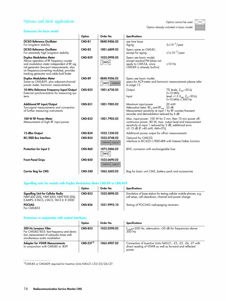
Options and their applications
Extensions for basic model
Option Order No. Specifications
OCXO Reference OscillatorFor long-term stability
CMS-B1 0840.9406.02 see time baseAging 2x10⁻⁷/year
OCXO Reference OscillatorFor extremely high long-term stability
CMS-B2 1001.6809.02 Specs same as CMS-B1, except for aging ≤1x10⁻⁷/year
Duplex Modulation MeterAllows operation of RF frequency counter and modulation meter independent of RF sig-nal generator (two-port measurements, also on frequency-converting modules); provides tracking generator and cable fault finder
CMS-B59 1032.0990.02 Specs see basic model, except residual FM (does not apply to CMS54, since CMS-B9 is already built-in)
≤10 Hz
Duplex Modulation MeterSame as CMS-B59, plus adjacent-channel power meter, harmonic measurements
CMS-B9 0840.9506.02 Specs see basic model,specs for ACP-meter and harmonic measurements please refer to page 13
10-MHz Reference Frequency Input/OutputExternal synchronization for measuring sys-tems
CMS-B22 1001.6750.02 Output
Input
TTL levels, Zout≈50 Ω, f=10 MHzlevel >1.5 Vpp, Zin≈50 Ω, f=10 MHz ± 500 Hz
Additional RF Input/OutputTwo-signal measurements and connection of further measuring instruments
CMS-B31 1001.7005.02 Maximum input power 20 mWAttenuation betw. RFin and RFout 32 dBMeasurement sensitivity at input 1 for RF counter/transient recorder and demodulation reduced by 6 dB
100-W RF Power MeterMeasurement of high RF input power
CMS-B32 1001.7905.02 Max. input power: 100 W for 3 min, then 10 min power off; continuous power: 80 W, max. output level and measurement sensitivity at input 1 reduced by 3 dB; additional error ≤0.15 dB (P >40 mW, AM=0%)
13-dBm Output CMS-B34 1032.1350.02 Additional power output for off-air measurements
IEC/IEEE-Bus Interface CMS-B54 1032.0748.02 Optional for CMS50;interface to IEC625-1/IEEE488 with listener/talker function
Protection for Input 2 CMS-B60 1075.5006.02 BNC connector with exchangeable fuse
Front Panel Grips CMS-B50 1032.0690.02
Carrier Bag for CMS CMS-Z40 1065.5603.02 Bag for basic unit CMS, battery pack and accessories
Signalling units for models with Duplex Modulation Meter CMS-B9 or CMS-B59
Option Order No. Specifications
Signalling Unit for Cellular RadioNMT450 (SIS), NMT450I, NMT900 (SIS), E-AMPS, E-TACS, J-TACS, TACS II, R 2000
CMS-B53 1032.0890.02 Simulation of base station for testing cellular mobile phones, e.g. call setup, call cleardown, channel and power change
POCSAGFor CMS-B53
CMS-B26 1031.9993.10 Testing of POCSAG radiopaging receivers
Extensions in conjunction with control interfaces
Option Order No. Specifications
300-Hz Lowpass FilterFor CMS-B5/-B55; fast frequency and devia-tion measurement of subaudio tones with simultaneous audio modulation
CMS-B33 1032.0290.02 fcutoff=200 Hz, attenuation >50 dB for frequencies above 300 Hz
Adapter for VSWR MeasurementsIn conjunction with CMS-B5 or -B39
CMS-Z371)
1)CMS-B5 or CMS-B39 required for Insertion Units NAS-Z1/-Z3/-Z5/-Z6/-Z7.
1065.4907.02 Connection of Insertion Units NAS-Z1, -Z3, -Z5, -Z6, -Z7 with direct reading of VSWR as well as forward and reflected power
CMS54
CMS50 CMS54
CMS57CMS54
CMS50
CMS57CMS54
Option cannot be used
Option already included in basic model
Cms_23.fm Seite 16 Freitag, 27. April 2001 3:27 15
Radiocommunication Service Monitor CMS 17
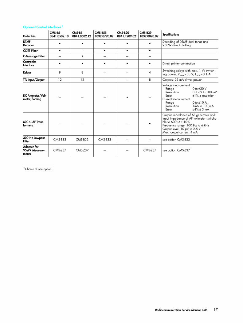
Optional Control Interfaces1)
Order No.CMS-B50841.0502.10
CMS-B50841.0502.12
CMS-B551032.0790.02
CMS-B200841.1209.02
CMS-B391032.0090.02 Specifications
DTMFDecoder • • • • • Decoding of DTMF dual tones and
VDEW direct dialling
CCITT Filter • — • • •
C-Message Filter — • — — —
Centronics Interface • • • • • Direct printer connection
Relays 8 8 — — 4 Switching relays with max. 1 W switch-ing power, Vmax=30 V, Imax=0.1 A
TTL Input/Output 12 12 — — 8 Outputs: 25 mA driver power
DC Ammeter/Volt-meter, floating — — — • —
Voltage measurementRangeResolutionError
Current measurementRangeResolutionError
0 to ±30 V0.1 mV to 100 mV±1% + resolution
0 to ±10 A1mA to 100 mA≤4% ± 3 mA
600-Ω AF Trans-formers — — — — •
Output impedance of AF generator and input impedance of AF voltmeter switcha-ble to 600 Ω ± 10%Frequency range: 100 Hz to 6 kHzOutput level: 10 µV to 2.5 VMax. output current: 4 mA
300-Hz Lowpass Filter CMS-B33 CMS-B33 CMS-B33 — — see option CMS-B33
Adapter for VSWR Measure-ments
CMS-Z37 CMS-Z37 — — CMS-Z37 see option CMS-Z37
1)Choice of one option.
Cms_23.fm Seite 17 Freitag, 27. April 2001 3:27 15
18 Radiocommunication Service Monitor CMS
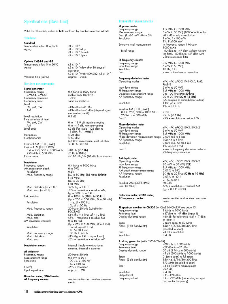
Specifications (Base Unit)
Valid for all models; values in bold enclosed by brackets refer to CMS50
TimebaseStandardTemperature effect 0 to 35°C ≤1 x 10⁻⁶
Aging ≤1 x 10⁻⁷/day≤1 x 10−6 /month≤2 x 10−6 /year
Options CMS-B1 and -B2Temperature effect 0 to 50°C ≤1 x 10⁻⁷
Aging ≤5 x 10⁻⁹/day after 30 days of operation ≤2 x 10⁻⁷/year (CMS-B2: ≤1 x 10⁻⁷)
Warmup time (25°C) approx. 10 min
Receiver measurementsSignal generatorFrequency range 0.4 MHz to 1000 MHz
CMS54, CMS 57 usable from 100 kHzFrequency resolution 10 Hz Frequency error same as timebaseLevel FM, ϕM, CW −134 dBm to 0 dBm AM −134 dBm to −3 dBm (depending on
modulation depth)Level resolution 0.1 dBFine variation of level FM, ϕM, CW 0 to −19.9 dB, non-interrupting AM 0 to −4.9 dB, non-interruptingLevel error ≤2 dB (for levels −128 dBm to
−3 dBm, f >1 MHz)1)Harmonics ≤−25 dBc Nonharmonics ≤−50 dBc
(>5 kHz from carrier, level −3 dBm)Residual AM (CCITT, RMS) ≤0.03% (≤0.1%)Residual FM (CCITT, RMS) 0.4 to 250, 500 to 1000 MHz ≤10 Hz (≤10 Hz) 250 MHz to 500 MHz ≤5 Hz (≤10 Hz)Phase noise ≤−110 dBc/Hz (20 kHz from carrier)
ModulationFrequency range 0.4 MHz to 1000 MHzAM modulation depth 0 to 99% Resolution 0.5% Mod. frequency range DC to 10 kHz, (15 Hz to 10 kHz)
f <8 MHz;DC to 20 kHz,f ≥8 MHz
Mod. distortion (m <0.8)1) ≤2%, fAF = 1 kHz Mod. error (m <0.8)1) ≤5% + resolution + residual AM,
fAF = 300 Hz to 3 kHzFM deviation 0 to 100 kHz (50 Hz to 50 kHz)
(fRF = 250 to 500 MHz, 0 to 50 kHz) Resolution 1 Hz, ∆f <100 Hz
1%, ∆f ≥100 Hz Mod. frequency range 20 Hz to 20 kHz (suitable for
POCSAG) Mod. distortion ≤1% (fAF = 1 kHz; ∆f = 10 kHz) Mod. error ≤5% + resolution + residual FMϕM deviation (internal) 0 to 10 rad
(fRF = 250 to 500 MHz, 0 to 5 rad) Resolution 1 mrad, ∆ϕ <0.1 rad
1%, ∆ϕ ≥0.1 rad Mod. frequency range 100 Hz to 6 kHz Mod. distortion ≤1% (fAF = 1 kHz; ∆ϕ = 1 rad) Mod. error ≤5% + resolution + residual ϕM
Modulation modes internal (single-tone/two-tone), external, internal + external
AF voltmeterFrequency range 50 Hz to 20 kHzMeasurement range 0.1 mV to 30 VResolution 100 µV, V <10 mV
1%, V ≥10 mVError2) <5% + resolutionInput impedance approx. 1 MΩ
Distortion meter, SINAD meter,AF frequency counter see transmitter and receiver measure-
ments
Transmitter measurementsRF power meterFrequency range 1.5 MHz to 1000 MHz Measurement range 5 mW to 50 W3) (100 W optionally)Error (P >20 mW, AM = 0%) ≤0.4 dB of rdg + resolutionResolution 1 mW, P <100 mW
1%, P ≥100 mWSelective level measurement in frequency range 1 MHz to
1000 MHz Level range −60 dBm to +47 dBm without weight-
ing filter, −80dBm to +47 dBm with 2-kHz resonance filter
RF frequency counterFrequency range 0.5 MHz to 1000 MHzInput level range 5 mW to 50 W3)Resolution 10 Hz, 1 HzError same as timebase + resolution
Frequency deviation meterOperating modes +PK, −PK, ±PK/2, PK HOLD, RMS,
RMS√2Input level range 5 mW to 50 W3)RF frequency range 1.5 MHz to 1000 MHzDeviation measurement range 0 to 100 kHz (0 to 50 kHz)AF frequency range 20 to 20 kHz (20 to 15 kHz)
(DC-coupled at demodulator output)Resolution 1 Hz, ∆f <1 kHz
1%, ∆f ≥1 kHzResidual FM (CCITT, RMS) 0.4 to 250, 500 to 1000 MHz ≤10 Hz 250MHz to 500 MHz ≤5 Hz (≤10 Hz)Error2) ≤5% + resolution + residual FM
Phase deviation meterOperating modes +PK, −PK, ±PK/2, RMS, RMS√2Input level range 5 mW to 50 W3) RF frequency range 1.5 MHz to 1000 MHzPhase deviation measurement range 0.001 rad to 5 radAF frequency range 300 Hz to 6 kHzResolution 0.001 rad, ∆ϕ ≤0.1 rad
1%, ∆ϕ >0.1 radError2) same as frequency deviation meter +
2% frequency response
AM depth meterOperating modes +PK, −PK, ±PK/2, RMS, RMS√2Input level range 20 mW to 50 W3) (PEP)RF frequency range 1.5 MHz to 1000 MHzAM depth measurement range 0.01% to 99%AF frequency range 50 Hz to 20 kHz (50 Hz to 10 kHz)Resolution 0.01%, m <0.1
0.1%, m ≥0.1Residual AM (CCITT, RMS) ≤0.03%Error (m ≤0.8)2) ≤7% + resolution + residual AM
(fAF = 0.3 to 3 kHz)
Distortion meter, SINAD meter,AF frequency counter see transmitter and receiver measure-
ments
RF spectrum monitor for CMS50 (for CMS54/CMS57 see page 13)Frequency range 1 MHz to 1000 MHzReference level +47dBm to −47 dBm (input 1)Display dynamic range >60 dB (for reference level >−7 dBm
at input 1)Span 0 (zero span) to 50 MHzFilters (3-dB bandwidth) 150 Hz, 6/16/50/300 kHz
(coupled to span)Error <3 dB + resolutionResolution 0.4 dB
Tracking generator (with CMS-B59/-B9)Frequency range 400 kHz to 1000 MHzReference level −27 dBm to −67 dBmDisplay dynamic range 50 dB (1 MHz to 500 MHz)
45 dB (500 MHz to 1000 MHz)Span 0 (zero span) to full spanFilters (3-dB bandwidth) 150 Hz, 6/16/50/300 kHz,
1/3 MHz (coupled to span)Error <3 dB (relative measurement
<0.5 dB)Resolution 0.4 dBOutput level 0 to −128 dBmFrequency offset 0 to ±999 MHz (depending on span
and center frequency)
Cms_23.fm Seite 18 Freitag, 27. April 2001 3:27 15
Radiocommunication Service Monitor CMS 19
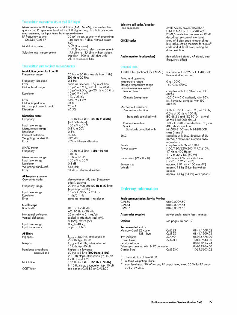
Transmitter measurements at 2nd RF inputMeasurement of RF frequency, modulation (AM, FM, ϕM), modulation fre-quency and RF spectrum (level) of small RF signals, e.g. in off-air or module measurements, for input levels from approximatelyRF frequency counter 30 µV (select. counter with presetting)
CMS54, CMS57 –40 dBm to +7 dBm (without preset-ting)
Modulation meter 5 µV (IF narrow)1 µV (IF narrow, select. measurement)
Selective level measurement −75 dBm to −35 dBm without weight-ing filter, −100 to −35 dBm with 2-kHz resonance filter
Transmitter and receiver measurementsModulation generator I and IIFrequency range 20 Hz to 30 kHz (usable from 1 Hz)
(20 Hz to 20 kHz)Frequency resolution 0.1 HzError same as timebase + 1/2 resolutionOutput level range 10 µV to 5 V, fAF=20 Hz to 20 kHz
10 µV to 2.5 V, fAF=20 Hz to 30 kHzResolution 10 µV, V <1 mV
1%, V ≥1 mVError ≤5%, V >1 mVOutput impedance ≤4 ΩMax. output current (peak) 20 mADistortion ≤0.5%
Distortion meterFrequency 100 Hz to 5 kHz (100 Hz to 3 kHz)
(in 10-Hz steps)Input level range 100 mV to 30 VMeasurement range 0.1% to 50%Resolution 0.1%Inherent distortion ≤0.5%Weighting bandwidth ≤12 kHzError ≤5% + inherent distortion
SINAD meterFrequency 100 Hz to 5 kHz (1 kHz ±10 Hz)
±10 HzMeasurement range 1 dB to 46 dBInput level range 100 mV to 30 VResolution 0.1 dBWeighting bandwidth ≤12 kHzError ≤1 dB + inherent distortion
AF frequency counterOperating modes demodulation, AF, beat (frequency
offset), externalFrequency range 20 Hz to 500 kHz (20 Hz to 20 kHz)
(superimposed RF)Input level range 10 mV to 30 V, f <20 kHzResolution 1 Hz/0.1 HzError same as timebase + resolution
OscilloscopeBandwidth DC: DC to 20 kHz
AC: 10 Hz to 20 kHzHorizontal deflection 20 ms/div to 0.1 ms/divVertical deflection scaled in kHz (FM), rad (ϕM),
% (AM), mV/V (AF)Input level range 0 Vp to 40 VpInput impedance approx. 1 MΩ
AF filtersHighpass fcutoff = 300 Hz, attenuation at
200 Hz typ. 40 dBLowpass fcutoff = 3.4 kHz, attenuation at
10 kHz typ. 40 dBBandpass broadband highpass + lowpass narrowband 50 Hz to 5 kHz (100 Hz to 3 kHz)
in 10-Hz steps, attenuation typ. 40 dB for 0.8f and 1.2f
Notch filter 100 Hz to 5 kHz (100 Hz to 3 kHz)in 10-Hz steps, attenuation typ. 40 dB
CCITT filter see options CMS-B5 or CMS-B20
Selective call coder/decoderTone sequences ZVEI1/ZVEI2/CCIR/EIA/EEA/
EURO/ NATEL/CCITT/VDEW/DTMF/user-defined sequences (DTMF decoding see control interface)
CDCSS coder entry of 3-digit code number of mo-bile radio, setting the times for turn-off code and RF level drop, setting the data deviation
Audio monitor (loudspeaker) demodulated signal, AF signal, beat (frequency offset)
General dataIEC/IEEE bus (optional for CMS50) interface to IEC 625-1/IEEE 488 with
listener/talker functionRated and operating temperature range 0 to +50°CStorage temperature range −40°C to +70°CEnvironmental resistance Temperature complies with IEC 68-2-1 and IEC
68-2-2 Climatic (damp heat) +25°C/+40°C cyclically with 95%
rel. humidity; complies with IEC 68-2-30
Mechanical resistance Sinusoidal vibration 5 Hz to 150 Hz, max. 2 g at 55 Hz,
0.5 g at 55Hz to 150 Hz Standards complied with IEC 68-2-6 and IEC 1010-1 as well
as MIL-T-28800D class 5 Random vibration 10 Hz to 300 Hz, acceleration 1.2 g rms Shock 40 g shock spectrum Standards complied with MIL-STD-810C and MIL-T-28800D
class 3 and 5EMC complies with EMC directive of EU
(89/336/EEC) and German EMC regulations
Safety complies with EN 61010-1Power supply (100/120/220/240) V AC ±10%,
47 Hz to 420 Hz or11 V to 32 V DC (50 W)
Dimensions (W x H x D) 320 mm x 175 mm x 375 mm(12.6“ x 6.9“ x 14.8“)
Screen size approx. 210 mm x 100 mm (9“)Weight approx. 13 kg (28.6 lbs) without
optionsapprox. 15 kg (33 lbs) with options
Ordering information
Radiocommunication Service MonitorCMS50 0840.0009.50CMS54 0840.0009.54CMS57 0840.0009.57
Accessories supplied power cable, spare fuses, manual
Options see pages 16 and 17
Recommended extras Memory Card 32 Kbyte CMS-Z1 0841.1609.02Memory Card 128 Kbyte CMS-Z2 0841.1509.0219" Adapter ZZA-99 0839.5775.00Transit Case ZZK-011 1013.9543.00Service Manual 0840.8616.24Telescopic antenna with BNC connector 0690.9966.00Carrier Bag CMS-Z40 1065.5603.02
1 ) Fine variation of level 0 dB.2 ) Without weighting filters.3 ) Input level max. 30 W for any RF output level, max. 50 W for RF output
level <−26 dBm.
Cms_23.fm Seite 19 Freitag, 27. April 2001 3:27 15
Prin
ted
in G
erm
any
0301
(Bi b
b)
ROHDE&SCHWARZ GmbH & Co. KG ⋅ Mühldorfstraße 15 ⋅ 81671 München ⋅ Germany ⋅ P.O.B. 8014 69 ⋅ 81614 München ⋅ Germany
Telephone +49894129-0 ⋅ www.rohde-schwarz.com ⋅ CustomerSupport: Tel. +491805124242, Fax +4989 4129-13777, E-mail: [email protected]
PD 7
57.1
031.
23 ⋅
Radi
ocom
mun
icat
ion
Serv
ice
Mon
itor C
MS
⋅ Tra
de n
ames
are
trad
emar
ks o
f the
ow
ners
⋅ Su
bjec
t to
chan
ge ⋅
Data
with
out t
oler
ance
s: ty
pica
l val
ues
ISO 9001Certified Quality System
DQS REG. NO 1954
Cms_23.fm Seite 20 Freitag, 27. April 2001 3:27 15
Related Documents