R450 VOIR NOTICE SEE NOTICE VOLT. STAB. I EXC STAT. FUSIBLES / FUSES 1k 3PH. S1 S2 50 Hz 60 Hz EXT FREQ SETTING LEDS US C Installation & maintenance manual : www.leroy-somer.com 380V 220 110 0V E- E+ Z2 X1 Z1 X2 7 LAM OFF LAM ON ONLY FOR SPECIAL CONFIG. KNEE LAM OFF 65Hz LAM OFF LAM MODE 2 LAM MODE 1 LAM OFF LAM MODE 2 LAM MODE 1 50Hz EXT.FREQ. SET. 60Hz 0 5 6 9 8 1 2 3 4 SERIES 7000 / 8000 SERIES 7000 / 8000 SERIES 5000 / 6000 SERIES 5000 / 6000 1 PHASE SENSING 3 PAHASES SENSING 2 3 0 1 RAPIDE FAST RAPIDE FAST NORMAL NORMAL NORMAL NORMAL SHUNT / AREP PMG 2 3 0 1 0 9 8 7 6 5 4 3 2 1 0 3 2 1 0 3 2 1 LSA49 / 50 LSA46 / 47 LSA46 / 47 LSA49 / 50 A.V.R. R450 Installation and maintenance CALL US TODAY 1-888-POWER-58 REQUEST A QUOTE [email protected] SHOP ONLINE www.genpowerusa.com/leroy-somer-avr/

Welcome message from author
This document is posted to help you gain knowledge. Please leave a comment to let me know what you think about it! Share it to your friends and learn new things together.
Transcript
R450
VOIR NOTICESEE NOTICE
VOLT. STAB. I EXC
STAT.
FUSIBLES / FUSES
1k3PH
.S1 S2
50 Hz60 Hz
EXT FREQSETTING
LEDS
USC
Installation & maintenance m
anual :www.leroy-som
er.com
380V 220 110 0V E- E+ Z2 X1 Z1 X2
7
LAMOFF
LAMON
ONLY FORSPECIALCONFIG.
KNEE
LAM OFF65Hz
LAMOFF
LAMMODE 2
LAMMODE 1
LAMOFF
LAMMODE 2
LAMMODE 1
50Hz
EXT.FREQ
.SET.
60Hz
056
981
234
SERIES
7000/8000
SERIES
7000/8000
SERIES
5000/6000
SERIES
5000/6000
1 PHASE SENSING
3 PAHASES SENSING2 3
01
RAPIDEFAST
RAPIDEFAST
NORMALNORM
AL
NORMALNORM
AL
SHUNT / AREP
PMG2 3
01
09876
54 3 210
32
10
32
1
LSA 49 / 50LSA 46 / 47
LSA 46 / 47LSA 49 / 50
A.V.R.
R450Installation and maintenance
CALL US TODAY 1-888-POWER-58
REQUEST A QUOTE [email protected]
SHOP ONLINE www.genpowerusa.com/leroy-somer-avr/
2
2016.06 / hElectric Power Generation Installation and maintenance
R450A.V.R.
4531 en -
SAFETY MEASURES
Before using your machine for the first time, it is important to read the whole of this installation and maintenance manual.
All necessary operations and interventions on this machine must be performed by a qualified technician.
Our technical support service will be pleased to provide any additional information you may require.
The various operations described in this manual are accompanied by recommen-dations or symbols to alert the user to potential risks of accidents. It is vital that you understand and take notice of the following warning symbols.
Warning symbol for an operation capable of damaging or destroying the machine or surrounding equipment.
Warning symbol for general danger to personnel.
Warning symbol for electrical danger to personnel.
All servicing or repair operations performed on the AVR should be undertaken by personnel trained in the commissioning, servicing and main-tenance of electrical and mechanical components.
When the generator is driven at a frequency less than 28 Hz for more than 30 seconds with an analogic regulator, the AC power must be disconnected.
WARNINGThis A.V.R. can be incorporated in a machine marked C.E.This manual is be given to the end user.
© - We reserve the right to modify the characteristics of its products at any time in order to incorporate the latest technological developments. The informa-tion contained in this document may therefore be changed without notice.
This document may not be reproduced in any form without prior authorization.All brands and models have been registered and patents applied for.
WARNING
This manual concerns the alternator A.V.R. which you have just purchased.We wish to draw your attention to the contents of this maintenance manual.
CALL US TODAY 1-888-POWER-58
REQUEST A QUOTE [email protected]
SHOP ONLINE www.genpowerusa.com/leroy-somer-avr/
3
2016.06 / hElectric Power Generation Installation and maintenance
R450A.V.R.
4531 en -
CONTENTS
1 - GENERAL INFORMATION ...............................................................................................4
1.1 - Description ...................................................................................................................41.2 - Characteristic ...............................................................................................................4
2 - POWER SUPPLY ...............................................................................................................5
2.1 - AREP excitation system ...............................................................................................52.2 - PMG excitation system .................................................................................................62.3 - SHUNT or separate excitation system ..........................................................................7
3 - TECHNICAL CHARACTERISTICS ....................................................................................8
3.1 - Electrical characteristics ...............................................................................................83.2 - Configurations ..............................................................................................................83.3 - U/F and LAM functions ...............................................................................................123.4 - Typical effects of the LAM with a diesel engine with or without a LAM (U/F only) ........123.5 - AVR options ...............................................................................................................13
4 - INSTALLATION - COMMISSIONING ...............................................................................14
4.1 - Electrical checks on the AVR ......................................................................................144.2 - Setting up ...................................................................................................................144.3 - Electrical faults ...........................................................................................................17
5 - SPARE PARTS .................................................................................................................18
5.1 - Designation ................................................................................................................185.2 - Technical support service ...........................................................................................18
Disposal and recycling instructions
CALL US TODAY 1-888-POWER-58
REQUEST A QUOTE [email protected]
SHOP ONLINE www.genpowerusa.com/leroy-somer-avr/
4
2016.06 / hElectric Power Generation Installation and maintenance
R450A.V.R.
4531 en -
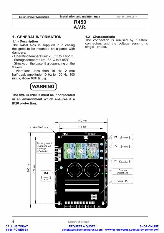
1 - GENERAL INFORMATION1.1 - DescriptionThe R450 AVR is supplied in a casing designed to be mounted on a panel with dampers.- Operating temperature: - 30°C to + 65° C.- Storage temperature: - 55°C to + 85°C.- Shocks on the base: 9 g depending on the 3 axes.- Vibrations: less than 10 Hz, 2 mm half-peak amplitude 10 Hz to 100 Hz: 100 mm/s, above 100 Hz: 8 g.
WARNING
The AVR is IP00, it must be incorporated in an environment which ensures it a IP20 protection.
1.2 - CharacteristicThe connection is realised by “Faston” connectors and the voltage sensing is single - phase.
R450
VOIR NOTICESEE NOTICE
VOLT. STAB. I EXC
STAT.
FUSIBLES / FUSES
1k3PH
.S1 S2
50 Hz60 Hz
EXT FREQSETTING
140 mm
LEDS
P1 Voltage
P2 Stability
P3 Excitation
Overrunindications
Fuses 10A
USC
Installation & maintenance m
anual :www.leroy-som
er.com
115 mm
380V 220 110 0V E- E+ Z2 X1 Z1 X2
200
mm
Rotating switch- Lam and U/F- Voltage- Excitation
4 holes Ø 6.5 mm
175
mm
50 Hz60 Hz
P4Quaddroop
7
LAMOFF
LAMON
ONLY FORSPECIALCONFIG.
KNEE
LAM OFF65Hz
LAMOFF
LAMMODE 2
LAMMODE 1
LAMOFF
LAMMODE 2
LAMMODE 1
50Hz
EXT.FREQ
.SET.
60Hz
056
981
234
SERIES
7000/8000
SERIES
7000/8000
SERIES
5000/6000
SERIES
5000/6000
1 PHASE SENSING
3 PAHASES SENSING2 3
01
RAPIDEFAST
RAPIDEFAST
NORMALNORM
AL
NORMALNORM
AL
SHUNT / AREP
PMG2 3
01
09876
54 3 210
3210
32
1LSA 49 / 50
LSA 46 / 47
LSA 46 / 47LSA 49 / 50
CALL US TODAY 1-888-POWER-58
REQUEST A QUOTE [email protected]
SHOP ONLINE www.genpowerusa.com/leroy-somer-avr/
5
2016.06 / hElectric Power Generation Installation and maintenance
R450A.V.R.
4531 en -
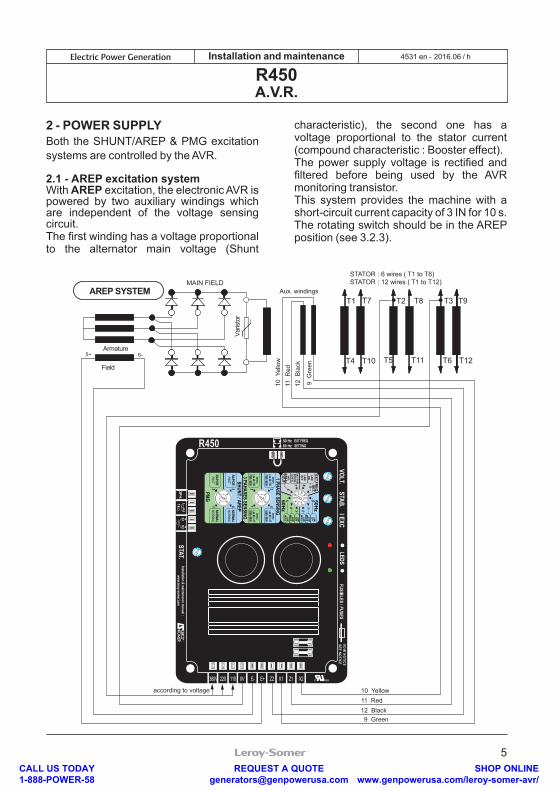
2 - POWER SUPPLYBoth the SHUNT/AREP & PMG excitation systems are controlled by the AVR.
2.1 - AREP excitation system With AREP excitation, the electronic AVR is powered by two auxiliary windings which are independent of the voltage sensing circuit.The first winding has a voltage proportional to the alternator main voltage (Shunt
characteristic), the second one has a voltage proportional to the stator current (compound characteristic : Booster effect).The power supply voltage is rectified and filtered before being used by the AVR monitoring transistor.This system provides the machine with a short-circuit current capacity of 3 IN for 10 s.The rotating switch should be in the AREP position (see 3.2.3).
AREP SYSTEM
Field
Armature
T1 T2 T3
T4 T5 T6
Varis
tor
5+ 6-
T7 T8 T9
T10 T11 T12
according to voltage
Aux. windings
10 Y
ello
w11
Red
9 G
reen
12 B
lack
10 Yellow11 Red
9 Green12 Black
STATOR : 6 wires ( T1 to T6)STATOR : 12 wires ( T1 to T12)
MAIN FIELD
R450
VOIR NOTICESEE NOTICE
VOLT. STAB. I EXC
STAT.
FUSIBLES / FUSES
1k3PH
.S1 S2
50 Hz60 Hz
EXT FREQSETTING
LEDS
USC
Installation & maintenance m
anual :www.leroy-som
er.com
380V 220 110 0V E- E+ Z2 X1 Z1 X2
7
LAMOFF
LAMON
ONLY FORSPECIALCONFIG.
KNEE
LAM OFF65Hz
LAMOFF
LAMMODE 2
LAMMODE 1
LAMOFF
LAMMODE 2
LAMMODE 1
50Hz
EXT.FREQ
.SET.
60Hz
056
981
234
SERIES
7000/8000
SERIES
7000/8000
SERIES
5000/6000
SERIES
5000/6000
1 PHASE SENSING
3 PAHASES SENSING2 3
01
RAPIDEFAST
RAPIDEFAST
NORMALNORM
AL
NORMALNORM
AL
SHUNT / AREP
PMG2 3
01
09876
54 3 210
32
10
32
1LSA 49 / 50
LSA 46 / 47
LSA 46 / 47LSA 49 / 50
CALL US TODAY 1-888-POWER-58
REQUEST A QUOTE [email protected]
SHOP ONLINE www.genpowerusa.com/leroy-somer-avr/
6
2016.06 / hElectric Power Generation Installation and maintenance
R450A.V.R.
4531 en -
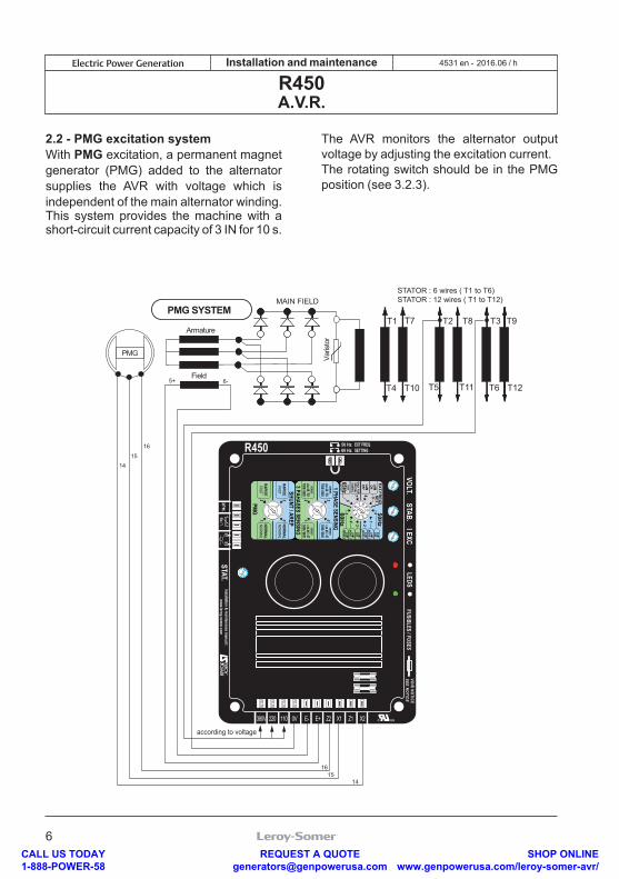
2.2 - PMG excitation systemWith PMG excitation, a permanent magnet generator (PMG) added to the alternator supplies the AVR with voltage which is independent of the main alternator winding. This system provides the machine with a short-circuit current capacity of 3 IN for 10 s.
The AVR monitors the alternator output voltage by adjusting the excitation current.The rotating switch should be in the PMG position (see 3.2.3).
PMG SYSTEM
PMG
T1 T2 T3
T4 T5 T6
Varis
tor
5+ 6-
14
14
15
15
16
16
T7 T8 T9
T10 T11 T12
according to voltage
Field
Armature
STATOR : 6 wires ( T1 to T6)STATOR : 12 wires ( T1 to T12)MAIN FIELD
R450
VOIR NOTICESEE NOTICE
VOLT. STAB. I EXC
STAT.
FUSIBLES / FUSES
1k3PH
.S1 S2
50 Hz60 Hz
EXT FREQSETTING
LEDS
USC
Installation & maintenance m
anual :www.leroy-som
er.com
380V 220 110 0V E- E+ Z2 X1 Z1 X2
7
LAMOFF
LAMON
ONLY FORSPECIALCONFIG.
KNEE
LAM OFF65Hz
LAMOFF
LAMMODE 2
LAMMODE 1
LAMOFF
LAMMODE 2
LAMMODE 1
50Hz
EXT.FREQ
.SET.
60Hz
056
981
234
SERIES
7000/8000
SERIES
7000/8000
SERIES
5000/6000
SERIES
5000/6000
1 PHASE SENSING
3 PAHASES SENSING2 3
01
RAPIDEFAST
RAPIDEFAST
NORMALNORM
AL
NORMALNORM
AL
SHUNT / AREP
PMG2 3
01
09876
54 3 210
32
10
32
1
LSA 49 / 50LSA 46 / 47
LSA 46 / 47LSA 49 / 50
CALL US TODAY 1-888-POWER-58
REQUEST A QUOTE [email protected]
SHOP ONLINE www.genpowerusa.com/leroy-somer-avr/
7
2016.06 / hElectric Power Generation Installation and maintenance
R450A.V.R.
4531 en -
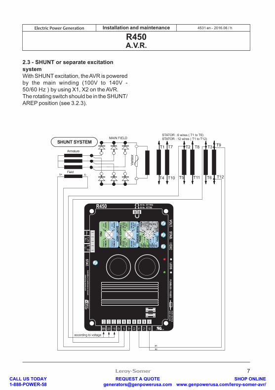
2.3 - SHUNT or separate excitation systemWith SHUNT excitation, the AVR is powered by the main winding (100V to 140V - 50/60 Hz ) by using X1, X2 on the AVR.The rotating switch should be in the SHUNT/AREP position (see 3.2.3).
SHUNT SYSTEMT1 T2 T3
T4 T5 T6
Varis
tor
5+ 6-
T7 T8 T9
T10 T11 T12
X2
X1
Field
Armature
STATOR : 6 wires ( T1 to T6)STATOR : 12 wires ( T1 to T12)MAIN FIELD
R450
VOIR NOTICESEE NOTICE
VOLT. STAB. I EXC
STAT.
FUSIBLES / FUSES
1k3PH
.S1 S2
50 Hz60 Hz
EXT FREQSETTING
LEDS
USC
Installation & maintenance m
anual :www.leroy-som
er.com
380V 220 110 0V E- E+ Z2 X1 Z1 X2
according to voltage
7
LAMOFF
LAMON
ONLY FORSPECIALCONFIG.
KNEE
LAM OFF65Hz
LAMOFF
LAMMODE 2
LAMMODE 1
LAMOFF
LAMMODE 2
LAMMODE 1
50Hz
EXT.FREQ
.SET.
60Hz
056
981
234
SERIES
7000/8000
SERIES
7000/8000
SERIES
5000/6000
SERIES
5000/6000
1 PHASE SENSING
3 PAHASES SENSING2 3
01
RAPIDEFAST
RAPIDEFAST
NORMALNORM
AL
NORMALNORM
AL
SHUNT / AREP
PMG2 3
01
09876
54 3 210
32
10
32
1
LSA 49 / 50LSA 46 / 47
LSA 46 / 47LSA 49 / 50
CALL US TODAY 1-888-POWER-58
REQUEST A QUOTE [email protected]
SHOP ONLINE www.genpowerusa.com/leroy-somer-avr/
8
2016.06 / hElectric Power Generation Installation and maintenance
R450A.V.R.
4531 en -
3 - TECHNICAL CHARACTERISTICS3.1 - Electrical characteristics- maximum power supply: 150V - 50/60 Hz- Rated overload current: 10 A - 10 s- Electronic protection: - In the case of a short-circuit, the excitation current is reduced to a value less than 1A after 10 s - In the event of loss of voltage reference, the excitation current is reduced to a value less than 1A after 1s for AREP/SHUNT, 10 s for PMG. - In the event of overexcitation, the current is reduced as indicated in the next diagram (see 3.2.1.4).- Fuses: F1 on X1 and F2 on Z2 10A, 250V.- Voltage sensing • 0-110 V terminals = 95 to 140 V • 0-220 V terminals = 170 to 260 V • 0-380 V terminals = 340 to 528 VFor other voltages, a transformer should be used.- Voltage regulation:± 0.5%.- Current sensing: (parallel operation): input S1, S2 intended for 1 C.T. < 2.5 VA cl1, secondary 1 A or 5 A.
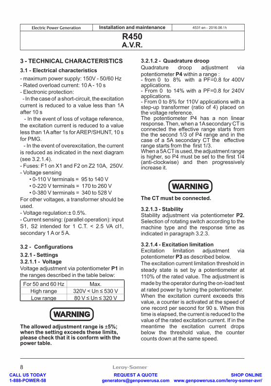
3.2 - Configurations 3.2.1 - Settings3.2.1.1 - VoltageVoltage adjustment via potentiometer P1 in the ranges described in the table below:For 50 and 60 Hz Max.
High range 320V < Un ≤ 530 V Low range 80 V ≤ Un ≤ 320 V
WARNINGThe allowed adjustment range is ±5%; when the setting exceeds these limits, please check that it is conform with the power table.
3.2.1.2 - Quadrature droopQuadrature droop adjustment via potentiometer P4 within a range :- from 0 to 8% with a PF=0.8 for 400V applications.- From 0 to 14% with a PF=0.8 for 240V applications.- From 0 to 8% for 110V applications with a step-up transformer (ratio of 4) placed on the voltage reference.The potentiometer P4 has a non linear response. Then, when a 1A secondary CT is connected the effective range starts from the the second 1/3 of P4 range and in the case of a 5A secondary CT the effective range starts from the first 1/3.When a 5A CT is used, the adjustment rangeis higher, so P4 must be set to the first 1/4 (anti-clockwise) and then progressively increase it.
WARNINGThe CT must be connected.
3.2.1.3 - StabilityStability adjustment via potentiometer P2. Selection of rotating switch according to the machine type and the response time as indicated in paragraph 3.2.3.
3.2.1.4 - Excitation limitationExcitation limitation adjustment via potentiometer P3 as described below.The excitation current limitation threshold in steady state is set by a potentiometer at 110% of the rated value. The adjustment is made by the operator during the on-load test at rated power by tuning the potentiometer.When the excitation current exceeds this value, a counter is activated at the speed of one record per second for 90 s. When this time is elapsed, the current is reduced to the value of the rated excitation current. If in the meantime the excitation current drops below the threshold value, the counter counts down at the same speed.
CALL US TODAY 1-888-POWER-58
REQUEST A QUOTE [email protected]
SHOP ONLINE www.genpowerusa.com/leroy-somer-avr/
9
2016.06 / hElectric Power Generation Installation and maintenance
R450A.V.R.
4531 en -
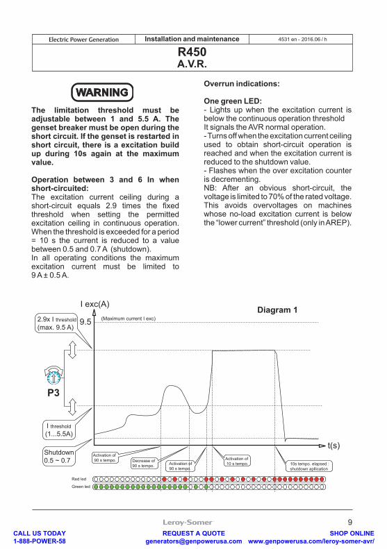
WARNINGThe limitation threshold must be adjustable between 1 and 5.5 A. The genset breaker must be open during the short circuit. If the genset is restarted in short circuit, there is a excitation build up during 10s again at the maximum value. Operation between 3 and 6 In when short-circuited:The excitation current ceiling during a short-circuit equals 2.9 times the fixed threshold when setting the permitted excitation ceiling in continuous operation. When the threshold is exceeded for a period = 10 s the current is reduced to a value between 0.5 and 0.7 A (shutdown).In all operating conditions the maximum excitation current must be limited to 9 A ± 0.5 A.
Overrun indications:
One green LED:- Lights up when the excitation current is below the continuous operation thresholdIt signals the AVR normal operation.- Turns off when the excitation current ceiling used to obtain short-circuit operation is reached and when the excitation current is reduced to the shutdown value.- Flashes when the over excitation counter is decrementing.NB: After an obvious short-circuit, the voltage is limited to 70% of the rated voltage. This avoids overvoltages on machines whose no-load excitation current is below the “lower current” threshold (only in AREP).
P3
Diagram 1 9.5
I exc(A)(Maximum current I exc)
Decrease of 90 s tempo. Activation of
90 s tempo.
Activation of 90 s tempo.
Red led
Green led
Activation of 10 s tempo. 10s tempo. elapsed :
shutdown apllication
t(s)
2.9x I threshold(max. 9.5 A)
I threshold(1...5.5A)
Shutdown0.5 ~ 0.7
CALL US TODAY 1-888-POWER-58
REQUEST A QUOTE [email protected]
SHOP ONLINE www.genpowerusa.com/leroy-somer-avr/
10
2016.06 / hElectric Power Generation Installation and maintenance
R450A.V.R.
4531 en -
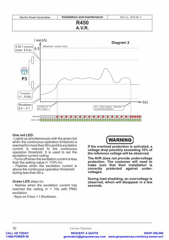
One red LED:- Lights up simultaneously with the green led when the continuous operation threshold is reached for more than 90 s and the excitation current is reduced to the continuous operation threshold. It is used to set the excitation current ceiling- Turns off when the excitation current is less than the setting value (< 110% In)- Flashes when the excitation current is above the continuous operation threshold during less than 90 s.
Green LED stays on,- flashes when the excitation current has reached the ceiling in < 10s with PMG excitation.- ftays on if Iexc = I Shutdown.
WARNINGIf the overload protection is activated, a voltage drop possibly exceeding 10% of the reference voltage will be observed.The AVR does not provide undervoltage protection. The customer will need to make sure that their installation is correctly protected against under-voltages.
During load shedding, an overvoltage is observed, which will disappear in a few seconds.
P3
Diagram 2 9.5
I exc(A)
t(s)
(Maximum current I exc)
Activation of 90 s. tempo
Red led
Green led
90 s. tempo elapsed : application of permanent limitation
2.9x I threshold(max. 9.5 A)
I threshold(1...5.5A)
Shutdown0.5 ~ 0.7
CALL US TODAY 1-888-POWER-58
REQUEST A QUOTE [email protected]
SHOP ONLINE www.genpowerusa.com/leroy-somer-avr/
11
2016.06 / hElectric Power Generation Installation and maintenance
R450A.V.R.
4531 en -
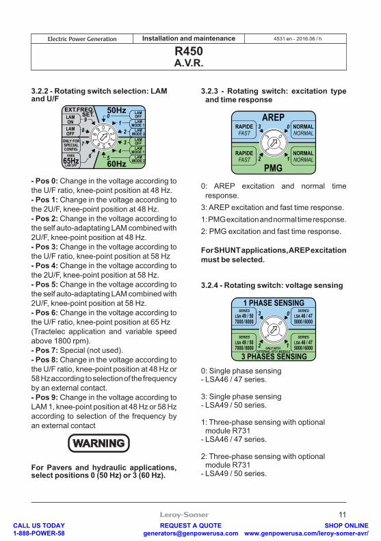
3.2.2 - Rotating switch selection: LAM and U/F
7
LAMOFF
LAMON
ONLY FORSPECIALCONFIG.
KNEE
LAM OFF65Hz
LAMOFF
LAMMODE 2
LAMMODE 1
LAMOFF
LAMMODE 2
LAMMODE 1
50HzEXT.FREQ.SET.
60Hz
0
56
9
81
2
34
09
87 6 5 4
321
- Pos 0: Change in the voltage according to the U/F ratio, knee-point position at 48 Hz.- Pos 1: Change in the voltage according to the 2U/F, knee-point position at 48 Hz.- Pos 2: Change in the voltage according to the self auto-adaptating LAM combined with 2U/F, knee-point position at 48 Hz. - Pos 3: Change in the voltage according to the U/F ratio, knee-point position at 58 Hz- Pos 4: Change in the voltage according to the 2U/F, knee-point position at 58 Hz.- Pos 5: Change in the voltage according to the self auto-adaptating LAM combined with 2U/F, knee-point position at 58 Hz.- Pos 6: Change in the voltage according to the U/F ratio, knee-point position at 65 Hz (Tractelec application and variable speed above 1800 rpm).- Pos 7: Special (not used).- Pos 8: Change in the voltage according to the U/F ratio, knee-point position at 48 Hz or 58 Hz according to selection of the frequency by an external contact.- Pos 9: Change in the voltage according to LAM 1, knee-point position at 48 Hz or 58 Hz according to selection of the frequency by an external contact
WARNING
For Pavers and hydraulic applications, select positions 0 (50 Hz) or 3 (60 Hz).
3.2.3 - Rotating switch: excitation type and time response
RAPIDEFAST
RAPIDEFAST
NORMALNORMAL
NORMALNORMAL
AREP
PMG2
3 0
1
03
2 1
0: AREP excitation and normal time response.
3: AREP excitation and fast time response.1: PMG excitation and normal time response.2: PMG excitation and fast time response.
For SHUNT applications, AREP excitation must be selected.
3.2.4 - Rotating switch: voltage sensing
SERIES
7000 / 8000
SERIES
7000 / 8000
SERIES
5000 / 6000
SERIES
5000 / 6000
1 PHASE SENSING
ONLY WITH EXTERNAL R731 MODULE
3 PHASES SENSING2
3 0
1
03
2 1
LSA 49 / 50
LSA 49 / 50
LSA 46 / 47
LSA 46 / 47
0: Single phase sensing- LSA46 / 47 series.
3: Single phase sensing- LSA49 / 50 series. 1: Three-phase sensing with optional module R731
- LSA46 / 47 series.
2: Three-phase sensing with optional module R731
- LSA49 / 50 series.
CALL US TODAY 1-888-POWER-58
REQUEST A QUOTE [email protected]
SHOP ONLINE www.genpowerusa.com/leroy-somer-avr/
12
2016.06 / hElectric Power Generation Installation and maintenance
R450A.V.R.
4531 en -
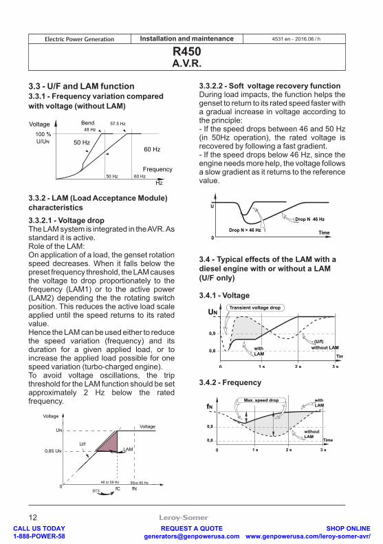
3.3 - U/F and LAM function3.3.1 - Frequency variation compared with voltage (without LAM)
100 %
50 Hz 60 HzHz
50 Hz
48 Hz57.5 Hz
60 Hz
Voltage Bend
U/UN
Frequency
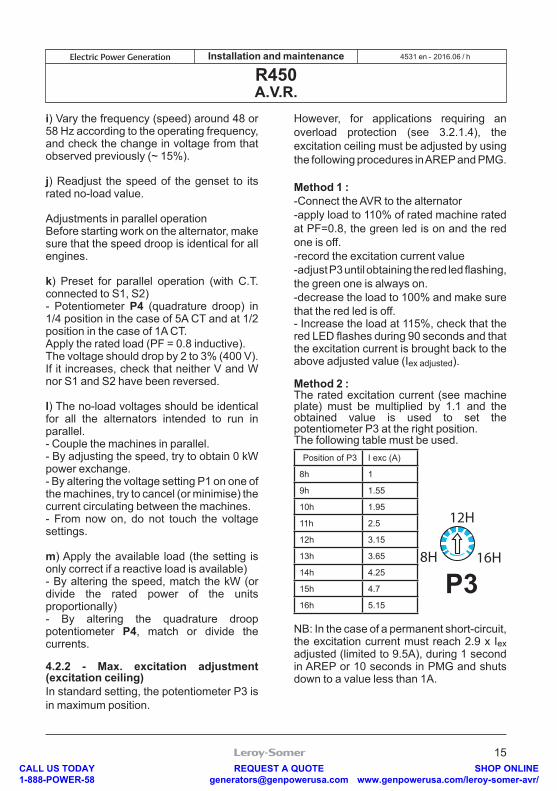
3.3.2 - LAM (Load Acceptance Module) characteristics3.3.2.1 - Voltage dropThe LAM system is integrated in the AVR. As standard it is active. Role of the LAM:On application of a load, the genset rotation speed decreases. When it falls below the preset frequency threshold, the LAM causes the voltage to drop proportionately to the frequency (LAM1) or to the active power (LAM2) depending the the rotating switch position. This reduces the active load scale applied until the speed returns to its rated value.Hence the LAM can be used either to reduce the speed variation (frequency) and its duration for a given applied load, or to increase the applied load possible for one speed variation (turbo-charged engine).To avoid voltage oscillations, the trip threshold for the LAM function should be set approximately 2 Hz below the rated frequency.
LAM
UN
048 or 58 Hz
0,85 UN
Voltage
Voltage
U/f
50 or 60 Hz
fC fNST3
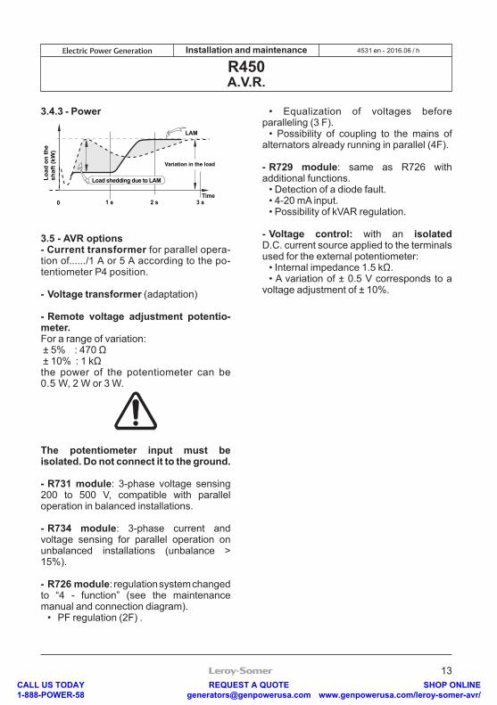
3.3.2.2 - Soft voltage recovery functionDuring load impacts, the function helps the genset to return to its rated speed faster with a gradual increase in voltage according to the principle:- If the speed drops between 46 and 50 Hz (in 50Hz operation), the rated voltage is recovered by following a fast gradient.- If the speed drops below 46 Hz, since the engine needs more help, the voltage follows a slow gradient as it returns to the reference value.
0Time
Drop N 46 Hz
U
Drop N > 46 Hz
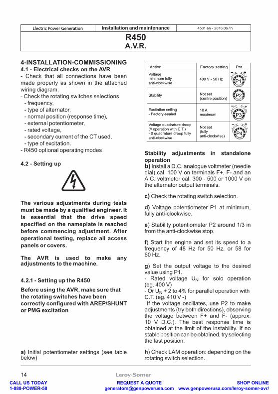
3.4 - Typical effects of the LAM with a diesel engine with or without a LAM (U/F only)
3.4.1 - Voltage
3.4.2 - Frequency
UN
0
0,9
0,8
(U/f)with LAM Time
without LAM
1 s 2 s 3 s
Transient voltage drop
0,9
0,8
fNMax. speed drop
0
with LAM
Time
without LAM
1 s 2 s 3 s
CALL US TODAY 1-888-POWER-58
REQUEST A QUOTE [email protected]
SHOP ONLINE www.genpowerusa.com/leroy-somer-avr/
13
2016.06 / hElectric Power Generation Installation and maintenance
R450A.V.R.
4531 en -
3.4.3 - Power
3.5 - AVR options - Current transformer for parallel opera-tion of....../1 A or 5 A according to the po-tentiometer P4 position.
- Voltage transformer (adaptation)
- Remote voltage adjustment potentio-meter.For a range of variation: ± 5% : 470 Ω ± 10% : 1 kΩthe power of the potentiometer can be 0.5 W, 2 W or 3 W.
The potentiometer input must be isolated. Do not connect it to the ground.
- R731 module: 3-phase voltage sensing 200 to 500 V, compatible with parallel operation in balanced installations.
- R734 module: 3-phase current and voltage sensing for parallel operation on unbalanced installations (unbalance > 15%).
- R726 module: regulation system changed to “4 - function” (see the maintenance manual and connection diagram). • PF regulation (2F) .
• Equalization of voltages before paralleling (3 F). • Possibility of coupling to the mains of alternators already running in parallel (4F).
- R729 module: same as R726 with additional functions. • Detection of a diode fault. • 4-20 mA input. • Possibility of kVAR regulation.
- Voltage control: with an isolated D.C. current source applied to the terminals used for the external potentiometer: • Internal impedance 1.5 kΩ. • A variation of ± 0.5 V corresponds to a voltage adjustment of ± 10%.
0 1 s 2 s 3 sTime
LAM
Variation in the load
Load
on
the
shaf
t (kW
)
Load shedding due to LAM
CALL US TODAY 1-888-POWER-58
REQUEST A QUOTE [email protected]
SHOP ONLINE www.genpowerusa.com/leroy-somer-avr/
14
2016.06 / hElectric Power Generation Installation and maintenance
R450A.V.R.
4531 en -
4 - INSTALLATION - COMMISSIONING4.1 - Electrical checks on the AVR- Check that all connections have been made properly as shown in the attached wiring diagram.- Check the rotating switches selections - frequency, - type of alternator, - normal position (response time), - external potentiometer, - rated voltage, - secondary current of the CT used, - type of excitation. - R450 optional operating modes
4.2 - Setting up
The various adjustments during tests must be made by a qualified engineer. It is essential that the drive speed specified on the nameplate is reached before commencing adjustment. After operational testing, replace all access panels or covers.
The AVR is used to make any adjustments to the machine.
4.2.1 - Setting up the R450Before using the AVR, make sure that the rotating switches have been correctly configured with AREP/SHUNT or PMG excitation
a) Initial potentiometer settings (see table below)
Action Factory setting Pot.
P1
P2
P3
P4
10 Amaximum
400 V - 50 Hz
Not set(centre position)
Not set(fully anti-clockwise)
Excitation ceiling- Factory-sealed
Voltage quadrature droop(// operation with C.T.)- 0 quadrature droop fully anti-clockwise
Voltageminimum fully anti-clockwise
Stability
Stability adjustments in standalone operationb) Install a D.C. analogue voltmeter (needle dial) cal. 100 V on terminals F+, F- and an A.C. voltmeter cal. 300 - 500 or 1000 V on the alternator output terminals.
c) Check the rotating switch selection.
d) Voltage potentiometer P1 at minimum, fully anti-clockwise. e) Stability potentiometer P2 around 1/3 in from the anti-clockwise stop.
f) Start the engine and set its speed to a frequency of 48 Hz for 50 Hz, or 58 for 60 Hz.
g) Set the output voltage to the desired value using P1.- Rated voltage UN for solo operation (eg. 400 V)- Or UN + 2 to 4% for parallel operation withC.T. (eg. 410 V -) If the voltage oscillates, use P2 to make adjustments (try both directions), observing the voltage between F+ and F- (approx. 10 V D.C.). The best response time is obtained at the limit of the instability. If no stable position can be obtained, try selecting the fast position.
h) Check LAM operation: depending on the rotating switch selection.
CALL US TODAY 1-888-POWER-58
REQUEST A QUOTE [email protected]
SHOP ONLINE www.genpowerusa.com/leroy-somer-avr/
15
2016.06 / hElectric Power Generation Installation and maintenance
R450A.V.R.
4531 en -
i) Vary the frequency (speed) around 48 or 58 Hz according to the operating frequency, and check the change in voltage from that observed previously (~ 15%).
j) Readjust the speed of the genset to its rated no-load value.
Adjustments in parallel operationBefore starting work on the alternator, make sure that the speed droop is identical for all engines.
k) Preset for parallel operation (with C.T. connected to S1, S2)- Potentiometer P4 (quadrature droop) in 1/4 position in the case of 5A CT and at 1/2 position in the case of 1A CT.Apply the rated load (PF = 0.8 inductive).The voltage should drop by 2 to 3% (400 V). If it increases, check that neither V and W nor S1 and S2 have been reversed.
l) The no-load voltages should be identical for all the alternators intended to run in parallel.- Couple the machines in parallel.- By adjusting the speed, try to obtain 0 kW power exchange.- By altering the voltage setting P1 on one of the machines, try to cancel (or minimise) the current circulating between the machines.- From now on, do not touch the voltage settings.
m) Apply the available load (the setting is only correct if a reactive load is available)- By altering the speed, match the kW (or divide the rated power of the units proportionally)- By altering the quadrature droop potentiometer P4, match or divide the currents.
4.2.2 - Max. excitation adjustment (excitation ceiling)In standard setting, the potentiometer P3 is in maximum position.
However, for applications requiring an overload protection (see 3.2.1.4), the excitation ceiling must be adjusted by using the following procedures in AREP and PMG.
Method 1 :-Connect the AVR to the alternator-apply load to 110% of rated machine rated at PF=0.8, the green led is on and the red one is off.-record the excitation current value-adjust P3 until obtaining the red led flashing, the green one is always on.-decrease the load to 100% and make sure that the red led is off.- Increase the load at 115%, check that the red LED flashes during 90 seconds and that the excitation current is brought back to the above adjusted value (Iex adjusted).
Method 2 :The rated excitation current (see machine plate) must be multiplied by 1.1 and the obtained value is used to set the potentiometer P3 at the right position.The following table must be used.
Position of P3 I exc (A)
8h 1
9h 1.55
10h 1.95
11h 2.5
12h 3.15
13h 3.65
14h 4.25
15h 4.7
16h 5.15
P38H
12H
16H
NB: In the case of a permanent short-circuit, the excitation current must reach 2.9 x Iex adjusted (limited to 9.5A), during 1 second in AREP or 10 seconds in PMG and shuts down to a value less than 1A.
CALL US TODAY 1-888-POWER-58
REQUEST A QUOTE [email protected]
SHOP ONLINE www.genpowerusa.com/leroy-somer-avr/
16
2016.06 / hElectric Power Generation Installation and maintenance
R450A.V.R.
4531 en -
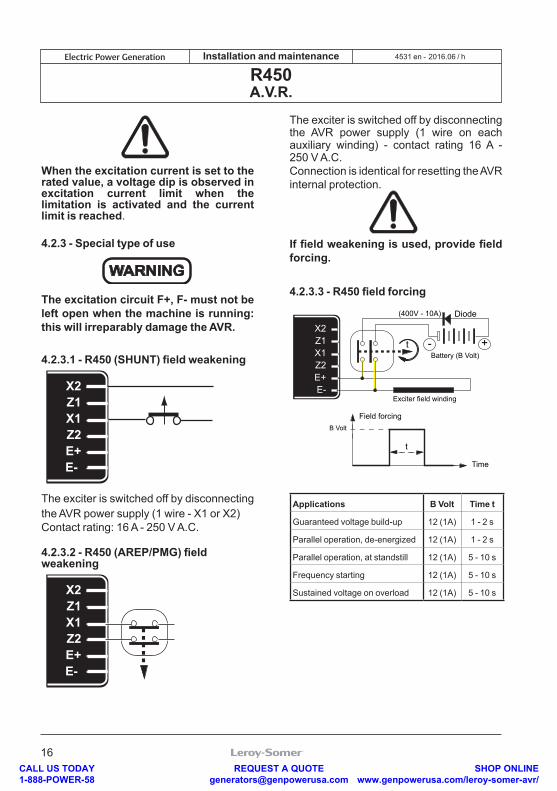
When the excitation current is set to the rated value, a voltage dip is observed in excitation current limit when the limitation is activated and the current limit is reached.
4.2.3 - Special type of use
WARNING
The excitation circuit F+, F- must not be left open when the machine is running: this will irreparably damage the AVR.
4.2.3.1 - R450 (SHUNT) field weakening
X2Z1X1Z2E+E-
The exciter is switched off by disconnecting the AVR power supply (1 wire - X1 or X2)Contact rating: 16 A - 250 V A.C.
4.2.3.2 - R450 (AREP/PMG) field weakening
X2Z1X1Z2E+E-
The exciter is switched off by disconnecting the AVR power supply (1 wire on each auxiliary winding) - contact rating 16 A - 250 V A.C.Connection is identical for resetting the AVR internal protection.
If field weakening is used, provide field forcing.
4.2.3.3 - R450 field forcing
Applications B Volt Time t
Guaranteed voltage build-up 12 (1A) 1 - 2 s
Parallel operation, de-energized 12 (1A) 1 - 2 s
Parallel operation, at standstill 12 (1A) 5 - 10 s
Frequency starting 12 (1A) 5 - 10 s
Sustained voltage on overload 12 (1A) 5 - 10 s
X2Z1X1Z2E+E-
Battery (B Volt) +-t
(400V - 10A)
Exciter field winding
Diode
t
B Volt
Field forcing
Time
CALL US TODAY 1-888-POWER-58
REQUEST A QUOTE [email protected]
SHOP ONLINE www.genpowerusa.com/leroy-somer-avr/
17
2016.06 / hElectric Power Generation Installation and maintenance
R450A.V.R.
4531 en -
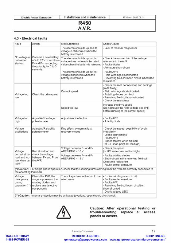
4.3 - Electrical faultsFault Action Measurements Check/Cause
No voltage at no load on start-up
Connect a new battery of 4 to 12 V to terminals F- and F+, respecting the polarity, for 2 to 3 seconds
The alternator builds up and its voltage is still correct when the battery is removed
- Lack of residual magnetism
The alternator builds up but its voltage does not reach the rated value when the battery is removed
- Check the connection of the voltage reference to the AVR- Faulty diodes- Armature short-circuit
The alternator builds up but its voltage disappears when the battery is removed
- Faulty AVR- Field windings disconnected- Revolving field coil open circuit. Check the resistance
Voltage too low
Check the drive speedCorrect speed
- Check the AVR connections and settings (AVR faulty)- Field windings short-circuited- Rotating diodes burnt out- Revolving field coil short-circuited- Check the resistance
Speed too lowIncrease the drive speed(Do not touch the AVR voltage pot. (P1) before running at the correct speed)
Voltage too high
Adjust AVR voltage potentiometer
Adjustment ineffective - Faulty AVR- 1 faulty diode
Voltage oscillations
Adjust AVR stability potentiometer
If no effect: try normal/fast recovery modes
- Check the speed: possibility of cyclic irregularity- Loose connections- Faulty AVR- Speed too low when on load (or U/F knee-point set too high)
Voltage correct at no load and too low when on load (*)
Run at no load and check the voltage between F+ and F- on the AVR
Voltage between F+ and F-AREP/PMG < 10 V
- Check the speed(or U/F knee-point set too high)
Voltage between F+ and F- AREP/PMG > 15 V
- Faulty rotating diodes- Short-circuit in the revolving field coil. Check the resistance - Faulty exciter armature
(*) Caution: For single-phase operation, check that the sensing wires coming from the AVR are correctly connected to the operating terminals.Voltage disappears during operation (**)
Check the AVR, the surge suppressor, the rotating diodes, and replace any defective components
The voltage does not return to the rated value
- Exciter winding open circuit- Faulty exciter armature- Faulty AVR- Revolving field coil open circuit or short-circuited- Overload (see LED)
(**) Caution: Internal protection may be activated (overload, open circuit, short-circuit)
Caution: After operational testing or troubleshooting, replace all access panels or covers.
CALL US TODAY 1-888-POWER-58
REQUEST A QUOTE [email protected]
SHOP ONLINE www.genpowerusa.com/leroy-somer-avr/
18
2016.06 / hElectric Power Generation Installation and maintenance
R450A.V.R.
4531 en -
5 - SPARE PARTS5.1 - DesignationDescription Type CodeVoltage regulator (AVR)
R450 AEM 110 RE 031
5.2 - Technical support serviceOur technical support service will be pleased to provide any additional information you may require.
When ordering spare parts, you should indicate the AVR type and code number.
Address your enquiry to your usual contact.
Our extensive network of service centres can dispatch the necessary parts without delay. To ensure correct operation and the safety of our machines, we recommend the use of original manufacturer spare parts.In the event of failure to comply with this advice, the manufacturer cannot be held responsible for any damage.
CALL US TODAY 1-888-POWER-58
REQUEST A QUOTE [email protected]
SHOP ONLINE www.genpowerusa.com/leroy-somer-avr/
19
2016.06 / hElectric Power Generation Installation and maintenance
R450A.V.R.
4531 en -
Disposal and recycling instructionsWe are committed to limit the environmental impact of our activity. We continuously survey our production processes, material sourcing and products design to improve recyclability and diminish our footprint.
These instructions are for information purposes only. It is the user responsibility to comply with local legislation regarding product disposal and recycling.
Recyclable materials Our alternators are mainly built out of iron, steel and copper materials, which can be reclaimed for recycling purposes.
These materials can be reclaimed through a combination of manual dismantling, mechanical separation and melting processes. Our technical support depar-tment can provide detailed directions on products dismounting upon request.
Waste & hazardous materials The following components and materials need a special treatment and need to be separated from the alternator before the recycling process:- electronic materials found in the terminal box, including the Automatic Voltage Regulator (198), Current Transformers (176), interference suppression module (199) and other semi-conductors.- diode Bridge (343) and Surge suppressor (347), found on the alternator rotor.- major plastic components, such as the terminal box structure on some products. These components are usually marked with plastic type information.
All materials listed above need special treatment to separate waste from reclaimable material and should be handed to specialized disposal companies.
The oil and grease from the lubrication system should be considered as a hazardous waste and has to be handled according to local legislation.
CALL US TODAY 1-888-POWER-58
REQUEST A QUOTE [email protected]
SHOP ONLINE www.genpowerusa.com/leroy-somer-avr/

20
2016.06 / hElectric Power Generation Installation and maintenance
R450A.V.R.
4531 en -
CALL US TODAY 1-888-POWER-58
REQUEST A QUOTE [email protected]
SHOP ONLINE www.genpowerusa.com/leroy-somer-avr/
21
2016.06 / hElectric Power Generation Installation and maintenance
R450A.V.R.
4531 en -
CALL US TODAY 1-888-POWER-58
REQUEST A QUOTE [email protected]
SHOP ONLINE www.genpowerusa.com/leroy-somer-avr/
22
2016.06 / hElectric Power Generation Installation and maintenance
R450A.V.R.
4531 en -
CALL US TODAY 1-888-POWER-58
REQUEST A QUOTE [email protected]
SHOP ONLINE www.genpowerusa.com/leroy-somer-avr/

Conception
Life Extension
Optimization
Start-up
Operation
•Consulting & specification•Maintenance
contracts
•Remanufacturing•System upgrade
•Monitoring•System audit
•Commissioning•Training
•Genuine spare parts•Repair services
Our worldwide service network of over 80 facilities is at your service.
This local presence is our guarantee for fast and efficient repair, support and maintenance services.
Trust your alternator maintenance and support to electric power generation experts. Our field personnel are 100% qualified and fully trained to operate in all environments and on all machine types.
We know alternators operation inside out, providing the best value service to optimize your cost of ownership.
Where we can help:
Contact us:Americas: +1 (507) 625 4011Europe & International: +33 238 609 908Asia Pacific: +65 6263 6334 China: +86 591 88373036India: +91 806 726 4867
[email protected] the code or go to:
www.lrsm.co/support
Service & Support
CALL US TODAY 1-888-POWER-58
REQUEST A QUOTE [email protected]
SHOP ONLINE www.genpowerusa.com/leroy-somer-avr/

www.emersonindustrial.comwww.emerson.com/epg
- 2016.06 / h4531 en
CALL US TODAY 1-888-POWER-58
REQUEST A QUOTE [email protected]
SHOP ONLINE www.genpowerusa.com/leroy-somer-avr/
Related Documents