User Manual Infrared Intelligent PTZ Camera Vehicle

Welcome message from author
This document is posted to help you gain knowledge. Please leave a comment to let me know what you think about it! Share it to your friends and learn new things together.
Transcript
User Manual
Infrared Intelligent PTZ CameraVehicle
AVUE
Typewritten Text
AVUE
Typewritten Text
AVUE Advanced Video Surveillance G55IR-WB36N
AVUE
Typewritten Text
AVUE
Typewritten Text
AVUE
Typewritten Text
AVUE
Typewritten Text
AVUE
Typewritten Text
AVUE
Typewritten Text
AVUE
Typewritten Text
AVUE
Typewritten Text
AVUE
Typewritten Text
TABLE OF CONTENT
1. Notice--------------------------------------------------------------------------------------------------------1
3. ------------------------------------------------------------------------5Function and operation instruction
4. ------------------------------------------------------------------------------------------------8System setting
2. Performance-----------------------------------------------------------------------------------------2
3.2 ----------- ---------- -------------------------- ---------- -------------------------------5Auto-run motion
3.4 ------------------- ------------------------------------------- -----------------------------------6Monitor function
4.1 ------------------ -------------------------------- -----------------------------------------8Basic operation
4.2 ----------- ------- -- -------------------------------------9------------------------- - --------------Edit dome label4.3 ------------ ---------------------------------10-------------------------------Display initial information
4.4 --------------- - -----------------------------11------------------------- -------------------Display setting
4.5 ------------ --- ----------------------------------------------------- ----------- -----------12System setting
4.6 ---------------- - --------------- 15------------------ ------- -----------------------------------------Clear
2.1 PTZ t ------------ - 2-------- -------------- ------------------------------------------echnology parameter
2.2 Camera parameter----------- --- 2----------------------------------------- - -----------------------------
2.3 Performance ----------- ----- 3-------------------------------------- --------------------------------& Feature
3.1 --------------- --- ----------------------------- ------------ ------------------------------5Set camera ID
3.3 ------------- - --------------------------- -- ----------------------------------------------------------6Camera control
4.1.1 ------- --- -- ---------------------- ------- -- ---------------------------------------------8Self-testing
4.1.2 ------------ - --------------------------------8------------------------- --------Call the main menu4.1.3 -------------------------------------------------8The operational ways of keyboard and menu
4.5.1 ------------ ----------- 12------------------------- -------------- ---------------------------Auto flip
4.5.2 Speed proportion pan------------- 12---------------------------------------------------------------
4.5.3 Park action---- ------ ---------------------- ----------------------------13--------- ------- ------------4.5.4 Power up action-------------- ---- 13------------------------- -------------------------------------
4.5.5 Fan startup by temperature-------------- ---- 13------------------------- ------------------------
4.5.6 Advance setting--------------------------------------------------------------------------------14
4.7 Password setup ---------------- - --------------- 16------------------ ------- ------------------------------
4.8 Clock setting ---------------- - --------------- 17------------------ ------- --------------------------------
5. Camera setting-------------- ----------- 19--------- --------------------------------------------------------
5.1 Zoom speed------------------- 19-----------------------------------------------------------------------
5.2 ------------- 0--------------------------------------------------------------------2Digital zoom control
5.3 ---------------------------------------------------------------------------21Back light compensation
5.4 Slow s ------------------------------------------------------------------------------------------22hutter
5.7 IR cut filter-----------------------------------------------------------------------------------------24
5.5 Line Sync control----------- ---- - ---------------------------23------------------ ------- ---------------
5.8Advance ------------------------------------------------------------------------------------25setting
5.8.1 -------------------------------------------------------------------------------------25AE mode
5.6 WDR control----------- ---- - ---------------------------------23------------------ ------- ---------------
4.9 Dome address ---------------- - --------------- 18------------------ ------- --------------------------------
7. -------------------------------------------------------------------------------------33Privacy zone masking
8. ---------------------------------------------------------------------------------------------34Alarm function
10. ----------------------------------------------------------------------------------------------------37Appendix
10.5.1 Baud rate setting------------------------------------------------------------------------42
10.5.3 ID setting----------------------------------------------------------------------------------42
10.5.2 Protocol setting------------------------------------------------------------------------------42
10.1 Menu index-----------------------------------------------------------------------------------------37
6. -------------------------------------------------------------------------------------------27Function setting
6.1 ------------- ------- --- 27--------------- ------- ------------------------------------------------------Preset
6.2 -------------- ------- 28--------------------------------- -----------------------------------------------Scan
6.3 ---------------- --------- 29--------------------------- ----------------------------------------------Pattern6.4 Tour------------ -- ----------------------------------- ------- -------------------------------------------306.5 ---------------- ------------------------------- -----------------------------------------------------31Zone
10.5 DIP switch setup---------------------------------------------------------------------------------------42
6.6 Time running---------------- ------------------------------- -------------------------------------------32
5.8.2 ---------- --------------------- ----------------------------------------26White balance mode
9. Set language -----------------------------------------------------------------------------------------------36
11.Installation instruction---------------------------------------------------------------------------------------47
12.Maintance service terms--------------------------------------------------------------------------------------52
11.1 Caution---------------------------------------------------------------------------------------------------47
11.3 -----------------------------------------------------------------------48Lightning Proof and Surge Proof
11.5 The preparation of installation-------------------------------------------------------------------------48
11.6 Structure introduction-----------------------------------------------------------------------------------49
11.7 Basic size graph------------------------------------------------------------------------------------------49
11. 9 Cabling connection--------------------------------------------------------------------------------------51
11.10 Electrification inspection------------------------------------------------------------------------------51
10.4 Rs485 Bus Basic Knowledge----------------------------------------------------------------------40
10.2 -------------------------3824VAC Wire Diameter and Transmission Distance Comparison chart
10.3 -------------------------------------------39Domestic andAbroad Wire Gauge Conversion Chart
11.2 Distributing the Line in Security-----------------------------------------------------------------------47
11.4 -----------------------------------------------------------------------------------------------48Water Proof
11.8 Installation ----------------------------------------------------------------------------------------------50
1
Precaution
Ø
Ø
Ø
Ø
Ø
Ø
Ø
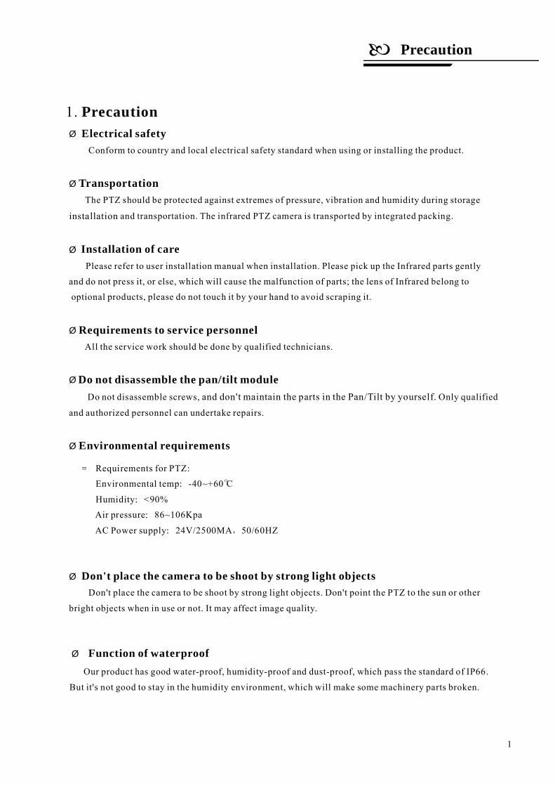
Conform to country and local electrical safety standard when using or installing the product.
The PTZ should be protected against extremes of pressure, vibration and humidity during storage
and transportation. The infrared
Infrared
Infrared
All the service work should be done by qualified technicians.
Do not disassemble screws, Only qualified
and authorized personnel can undertake repairs.
Don't place the camera to be shoot by strong light objects. Don't point the PTZ to the sun or other
bright objects when in use or not. It may affect image quality.
Electrical safety
Transportation
Installation of care
Requirements to service personnel
Do not disassemble the pan/tilt module
Environmental requirements
Don't place the camera to be shoot by strong light objects
installation
and don't maintain the parts in the Pan/Tilt by yourself.
PTZ camera is transported by integrated packing.
Please refer to user installation manual when installation. Please pick up the parts gently
and do not press it, or else, which will cause the malfunction of parts; the lens of belong to
optional products, please do not touch it by your hand to avoid scraping it.
1. Precaution
Ø Function of waterproofOur product has good water-proof, humidity-proof and dust-proof, which pass the standard of IP66.
But it's not good to stay in the humidity environment, which will make some machinery parts broken.
=
:
:
:
: ,
-40~+60 C
<90%
86~106Kpa
24V/2500MA 50/60HZ
O
Requirements for PTZ:
Environmental temp
Humidity
Air pressure
AC Power supply
Baud rate RS485( )
Consumption
Environmental humidity
Protection grade
Mount
Operational environment
Performance
Electrical:
Decoder Built-in
Alarm function 7 alarm input/2 alarm output
Power supply AC24V
Rotation speed Pan0.4 80 /S Tilt0.4 60 /S~ ° ~ °
2. 1 Technology parameter
Operation:
Pan rotation 360 continuously°
Preset Tour Scan Pattern、 、 、
Environmental:
-40 60℃~ +
Physical:
Setting:
2400/4800/9600/19200bps
Protocol Sixteen protocols, includingetc.Pelco,
Kalatel, Phlips, Diamond,
Address setting 0-254
Preset 128presets
Tilt rotation Tilt180 with auto flip°, 0 95% no compensation—
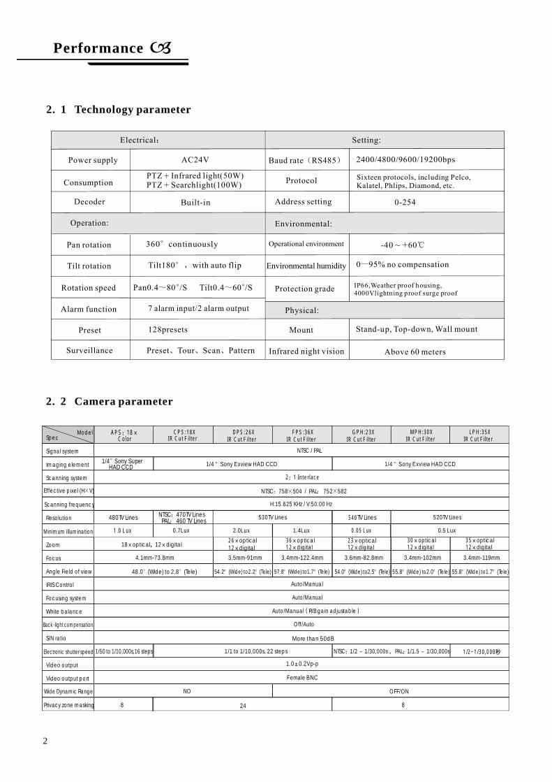
2. 2 Camera parameter
IP66,Weather proof housing,4000Vlightning proof surge proof
Stand-up, Top-down, Wall mount
Surveillance
2
PTZ + Infrared light(50W)PTZ + Searchlight(100W)
Infrared night vision Above 60 meters
Spec
Signal system
Imaging element
Scanning system
Effective pixel (H V)×
Scanning frequency
Resolution
Minimum illumination
Zoom
Focus
Angle Field of view
IRIS Control
Focusing system
White balance
Back -l ight compensation
S/N ratio
Electronic shutter speed
Video output
Video output po rt
Wide Dynamic Range
Privacy zone masking
CPS:18XIR Cut Filter
DPS:26XIR Cut Filter
FPS:36XIR Cut Filter
GPH:23XIR Cut Filter
MPH:30XIR Cut Filter
LPH:35XIR Cut Filter
NTSC / PAL
1/4 Sony Exview HAD CCD" 1/4 Sony Exview HAD CCD"
2:1 Interlace
NTSC 758 504 / PAL 752 582: × : ×
H:15.625 KHz / V:50.00 Hz
530TV Lines 520TV Lines
0.7Lux 2.0Lux 1.4Lux 0.5 Lux
18 optical 12 digital× , ×2612××
opticaldigital
3612××
opticaldigital
2312××
opticaldigital
3012××
opticaldigital
3512××
opticaldigital
4.1mm-73.8mm 3.5mm-91mm 3.4mm-122.4mm 3.6mm-82.8mm 3.4mm-102mm 3.4mm-119mm
48.0 (Wide) to 2.8 (Tele)° ° 54.2 2.2°(Wide) to (Tele)° 57.8 1.7°(Wide) to (Tele)° 54.0 2.5°(Wide) to (Tele)° 55.8 2.0°(Wide) to (Te le)° 55.8 1.7°(Wide) to (Tele)°
Auto/Manual
Auto/Manual
Auto/Manual R/B gain adjustable( )
Off/Auto
More than 50dB
1/1 to 1/10,000s, 22 s teps NTSC 1/2 1/30,000s PAL 1/1.5 1/30,000s: ~ , : ~ 1/2~1/30,000秒
1.0 0.2Vp-p±
Female BNC
NO OFF/ON
24 88
Model
540TV Lines
0.05 Lux
APS:18×Color
1/4 Sony SuperHAD CCD″
480TV Lines
1.0 Lux
1/50 to 1/10,000s,16 steps
NTSC 470TV LinesPAL 460 TV Lines::
AVUE
Typewritten Text
AVUE
Typewritten Text
AVUE
Typewritten Text
AVUE
Typewritten Text
↓
AVUE
Typewritten Text
3
Performance
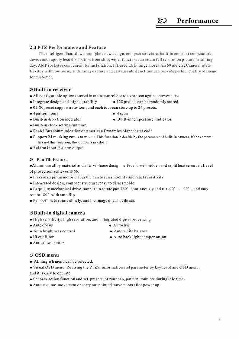
All configurable options stored in main control board to protect against power cutsIntegrate design and high durability 128 presets can be randomly stored01-80preset support auto-tour, and each tour can store up to 24 presets.4 pattern tours 4 scanBuilt-in direction indicator Built-in temperature indicatorBuilt-in clock setting functionRs485 Bus communication or American Dynamics Manchester codeSupport 24 masking zones at most
7 alarm input, 2 alarm output.
Exquisite mechanical drive, support to rotate pan 360 continuously and tilt -90 90 , and mayrotate 180 with auto flip.
High sensitivity, high resolution, and integrated digital processingAuto-focus Auto-IrisAuto brightness control Auto white balanceIR cut filter Auto back light compensationAuto slow shutter
All English menu can be selected.Visual OSD menu. Revising the PTZ's information and parameter by keyboard and OSD menu,
and it is easy to operate.Set park action function and set presets, or run scan, pattern, tour, etc during idle time.Auto-resume movement or carry out pointed movements after power up.
2.3
Built-in receiver
Built-in digital camera
OSD menu
Ø
Ø
Ø
Ø
Precise stepping motor drives the pan to run smoothly and react sensitivity.Integrated design, compact structure, easy to disassmeble.
Pan 0.4 /s to rotate slowly, and the image doesn't vibrate.
●
● ●
●
●
●
●
● ●
● ●
●
●
●
●
●
●
●
● ●
● ●
● ●
●
●
●
●
●
(This function is decide by the parameter of built-in camera, if the camerahas not this function, this option is invalid. )
Aluminum alloy material and anti-violence design surface is well hidden and rapid heat removal; Levelof protection achieves IP66.
° ° °
°
°
PTZ Performance and FeatureThe intelligent Pan/tilt was complete new design, compact structure, built-in constant temperature
device and rapidly heat dissipation from chip; wiper function can retain full resolution picture in rainingday; AMP socket is convenient for installation; Infrared LED range more than 60 meters; Camera rotateflexibly with low noise, wide range capture and certain auto-functions can provide perfect quality of imagefor customer.
Pan Tilt Feature
~ +
Ø
Set time displayWhen the temperature exceeds the limit, the screen will display alarm information.When the temperature is under the limit, the PTZ will delay to startup, and when the heat device
is heated and got higher than low limit temperature to startup.According to the temperature, the fan measures if it is to start or not, and prolong the life of fan.
Infrared LED range more than 60 meters, can manual control or auto-control infrared LED ON/OFF,manual control through keyboard can turn infrared LED ON/OFF. If auto-control working, image colorwill be switch to black and white when in low brightness, black and white will be switch to color when inhigh brightness.
Internal temperature test●
●
●
●
Night View Function
Ø
Ø
Ø
“ ”
Wiper functionWiper function can be set ON/OFF by calling 63 preset or OSD menu. In the raining day, the
wiper can not only ensure the high quality image, but also cleanup the dirtiness on the surface oflens.
Time runningBy the menu Time running ,user may set time running function everyday, and set different four
actions in four different time in one day, including preset, scan, pattern and tour.
Performance
4
Function Instruction
This passage mainly describes the main function and general principle of intelligence PTZ, and notrefer to the concrete operation methods. Different system platform has different operation methods, generally,should according to the system manufactory's operation manual. Please contact dealer to get necessaryinformation, there are some particular requirements and operations under specific condition.
and SW2 is for setting communication baudrate and controlling protocol. (For detail setting, please refer to 10.5 DIP switch setting)Besides the factory protocol(FACTORY), the PTZ is compatible with various popular protocols, such asPECLO-D, PECLO-P, ERNITEC, VCL, MOLYNX, VICON, SANTACHI, PANASONIC, SAMUNG,DIAMOND, KALATEL, LILIN, PHILIPS, VIDO B02 AD and so on.
Any controlling command must base on the objective camera address, and the camera only answer to thecontrolling command address which coincide with itself. There are three kinds of camera address:
When manually adjusting, for far focus situation, the PTZ responds at a high-speed so that touchingrocker slightly may make picture move rapidly, thus cause the picture to lose. To base on humanized design,the PTZ automatically adjust pan and tilt rotation according to zoom near and far, which make it isconvenient to operate manually to make tracking for the object. In the menu, you may change systemparameter setting proportion pan as ON to run this function.
If user holds the joystick in the down position, the camera rotates pan 180 degrees, he camerarotates tilts up to 180 degrees . In the menu, you may set the system parameter setting AUTO FLIP as ONto run this function.
By the menu park time and park action , user may set auto-call preset or run tour, pattern, andscan, etc after pointing a few minutes if the PTZ doesn't run any motions.
By the menu power up action , after the PTZ powers up or restarts, user may set auto- resumemovements before power up and auto- call preset or run tour, pattern, and scan etc .
Camera ID
Auto-run motion
Auto flip
Power up action
Use camera's switch number to set address 1-8 bits, the address range is 1-254.Debug address: (Only factory protocol and PELCO can be set) if camera ID is set 0, user may select
any address to control the PTZ.
3.1
3.2
Park action
There are two 8-bit switch SW1 and SW2 on the commutator,
,
“ ” “ ”
●
●
Common address:
Ø
Ø
Ø
Ø
Focus/speed proportion pan
“ ”
then t
3. Function Instruction
5
Function Instruction
3. 3 Camera controlMagnification control
Focus control
Iris control
Auto back light compensation
Auto white balance
3. 4 Monitor functionSet and call preset
Tour
Ø
Ø
Ø
Ø
Ø
Ø
Ø
The user can control Wide/Tele to adjust zoom far and near of the image by keyboard controller to obtainpanoramic image or close view that you need. The PTZ support digital zoom and optical zoom.
System defaultsAuto focus. When the lens changes, camera will auto-adjust focus according to the center ofthe image to get legible image; user can also manually focus to get desire image by operating keyboardFAR/NEAR .When operating keyboard joystick, camera resumes to auto focus.
The camera cannot auto focus in the following status:Target is not the center of the imageObservation the target near and far at the same time, can not be clear at the same time.
System defaultsAuto Iris. Camera can rapidly adjust size of Iris, through the automatically induct the changingof environment ray, and thus make the brightness of deferent image stable.
User may adjust Iris by controller keyboard open/close to get required brightness that you need. User alsocan resume auto Iris by joystick operation. When controlling the Iris manually, the PTZ locks current position youmanually controlled; when operating joystick, the PTZ resume auto Iris.
Camera sub-area can carry out auto back light compensation. Under a strong light background, camera will autocompensate light for the darker object and adjust daylight to the bright background. In order to avoid making theimage lack fidelity by the back line is too bright, and the object is unable to recognize because of darkness, thus gainlegible image.
Camera can automatically adjust white balance in accordance with the alteration of background lightnessto reach a true colour.
Preset function is that PTZ stores current pan/tilt angle, zoom and other position parameters into the memory.When necessary PTZ recalls these parameters and adjust camera to that position. User can store and recall presetseasily and promptly by using keyboard controlling. The PTZ can store up to 128 presets.
Auto tour is the built-in function in the PTZ, to make preset arranged in needful order in tour queueby programming in advance. To make camera tour between presets by inserting presets in cruise tour. It is feasible
to program tour order, each time as you run tour, you can set the park time of preset A tour can store 24 presets.
“ ”
“ ”
“ ”
.
●
●
●
●
●
●
●
Target is a strong light object, such as neon light, spotlight , etc.Target moves too fastTarget area such as wallTarget is too dark or vagueTarget image is too small
6
Ø
Ø
Ø
Ø
Ø
~ +
Scan
Pattern
Alarm input/output controlling function
Privacy zone masking
Lens position display
The operator can prompt set right limit and left limit in advance by keyboard and menu, so as to make the
camera repeatedly scanned between right and left limit at setting speed.
Pattern is built-in function in camera; the PTZ can record tracks that are no less than 180s, when running
pattern, the PTZ moves repeatedly according to the recorded tracks. A PTZ can set up to 4 pattern tours.
The PTZ receive an external alarm message, to implement the action that you preset, till the alarm release to
resume, if abnormity, it will send another alarm message. The PTZ can set up to 7 alarm input and 2 alarm
output.
The user can set a black shadow to mask the area so that it will not appear on the monitor to protect privacy.
This function is relative with the type of the PTZ, if zoom camera hasn't this function, it is invalid)
The position that the PTZ has finished to auto-checking as 0 point of pan movement and tilt movement. The pan
range is 0-360 , and tilt range is -90 90 . According to the displayed information, to set the position of camera
lens, and the position can display on the screen.
。
° ° °
a
(
Function Instruction
7
System Setting
4. 1. 1 Current-carrying to PTZ and
4. 1. 2 Call
4. 1. 3
IncreaseReduce
Press TELE and WIDE at the same time, it means 3D joystick rotates joystick cap.
【 】
【 】
【 】
【 】
【 】
【 】
【 】
【 】 【 】
OPEN
CLOSE
NEARTELEWIDE
.
Ø
Ø
“ ”
Self-testing
the main menu
Menu and keyboard operationKeyboard operation:
Menu operation
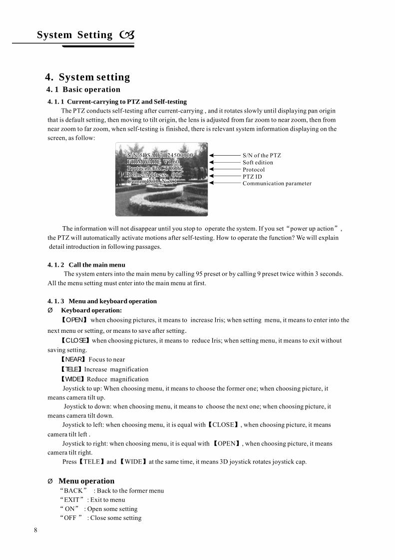
The PTZ conducts self-testing after current-carrying , and it rotates slowly until displaying pan originthat is default setting, then moving to tilt origin, the lens is adjusted from far zoom to near zoom, then fromnear zoom to far zoom, when self-testing is finished, there is relevant system information displaying on thescreen, as follow:
The information will not disappear until you stop to operate the system. If you set power up action ,the PTZ will automatically activate motions after self-testing. How to operate the function? We will explaindetail introduction in following passages.
The system enters into the main menu by calling 95 preset or by calling 9 preset twice within 3 seconds.All the menu setting must enter into the main menu at first.
when choosing pictures, it means to increase Iris; when setting menu, it means to enter into thenext menu or setting, or means to save after setting
when choosing pictures, it means to reduce Iris; when setting menu, it means to exit withoutsaving setting.
Focus to nearmagnificationmagnification
Joystick to up: When choosing menu, it means to choose the former one; when choosing picture, itmeans camera tilt up.
Joystick to down: when choosing menu, it means to choose the next one; when choosing picture, itmeans camera tilt down.
Joystick to left: when choosing menu, it is equal with CLOSE , when choosing picture, it meanscamera tilt left
Joystick to right: when choosing menu, it is equal with OPEN , when choosing picture, it meanscamera tilt right.
BACK : Back to the former menuEXIT : Exit to menuON : Open some settingOFF : Close some setting
“ ”
.
“ ”
“ ”
“ ”
Soft editionProtocolPTZ IDCommunication parameter
4. 1 Basic operation4. System setting
S/N of the PTZ
8
System setting
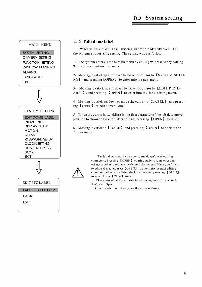
When using a lot of PTZs systems, in order to identify each PTZ,the systems support title setting. The setting ways as follow
The system enters into the main menu by calling 95 preset or by calling9 preset twice within 3 seconds.
Moving joystick up and down to move the cursor to SYSTEM SETTI-NG , and pressing OPEN to enter into the next menu.
Moving joystick up and down to move the cursor to EDIT PTZ L-ABEL , and pressing OPEN to enter into the label setting menu.
Moving joystick up/down to move the cursor to LABEL , and press-ing OPEN to edit current label.
When the cursor is twinkling in the first character of the label, to movejoystick to choose character, after editing, pressing OPEN to save.
Moving joystick to BACK and pressing OPEN to back to theformer menu.
’
:
、
、 【
】 【 】
、 【
】 【 】
、 【 】
【 】
、
【 】
、 【 】 【 】
1
2
3
4
5
6
EDIT PTZ LABEL
LABEL SPEED DOME
BACK
EXIT
:
4. 2 Edit dome label
The label may set 16 characters, and doesn't need editingcharacters. Pressing OPEN continuously to jump over andusing spacebar to replace the deleted characters. When you finishto edit a character, press OPEN to enter into the next editingcharacter; when you editing the last character, pressing OPENto save. Press Close to exit.
Characters of label available for choosing are as follow: 0- 9,A-Z,:<>-., Space.
Other labels input ways are the same as above.’
【 】
【 】
【 】
【 】
SYSTEM SETTING
EDIT DOME LABELINITIAL INFODISPLAY SETUPMOTIONCLEARPASSWORD SETUPCLOCK SETTING
BACKEXIT
DOME ADDRESS
9
MAIN MENU
SYSTEM SETTINGCAMERA SETTINGFUNCTION SETTINGWINDOW BLANKINGALARMSLANGUAGEEXIT
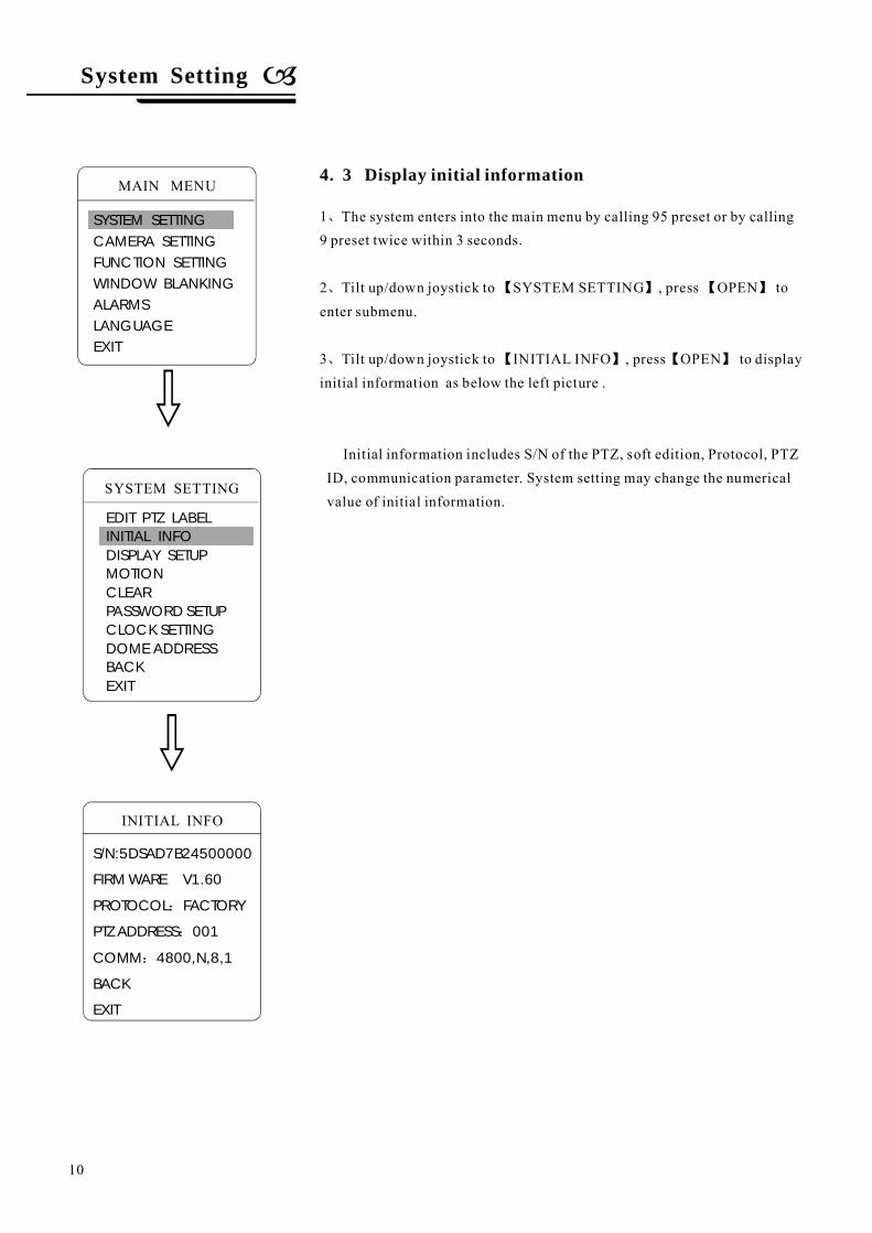
The system enters into the main menu by calling 95 preset or by calling9 preset twice within 3 seconds.
OPEN
OPEN
Tilt up/down joystick to SYSTEM SETTING , press toenter submenu.
Tilt up/down joystick to INITIAL INFO , press to displayinitial information as below the left picture .
Initial information includes S/N of the PTZ, soft edition, Protocol, PTZID, communication parameter. System setting may change the numericalvalue of initial information.
1
2
3
、
、
、
【 】 【 】
【 】 【 】
4. 3 Display initial information
INITIAL INFO
S/N:5DSAD7B24500000
FIRM WARE V1.60
PROTOCOL FACTORY
PTZ ADDRESS 001
COMM 4800,N,8,1
BACK
EXIT
:
:
:
SYSTEM SETTING
EDIT PTZ LABELINITIAL INFODISPLAY SETUPMOTIONCLEARPASSWORD SETUPCLOCK SETTING
BACKEXIT
DOME ADDRESS
System Setting
10
MAIN MENU
SYSTEM SETTINGCAMERA SETTINGFUNCTION SETTINGWINDOW BLANKINGALARMSLANGUAGEEXIT
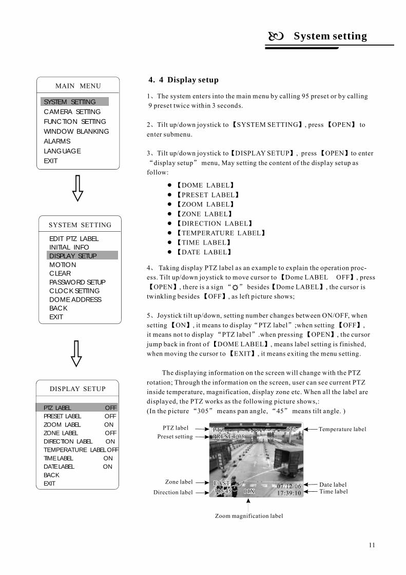
1 The system enters into the main menu by calling 95 preset or by calling9 preset twice within 3 seconds.
2 Tilt up/down joystick to SYSTEM SETTING , press OPEN toenter submenu.
3 Tilt up/down joystick to DISPLAY SETUP , press OPEN to enterdisplay setup menu, May setting the content of the display setup as
follow:
LABEL OFFOPEN LABEL
OFF
ON when setting OFF ,it means not to display PTZ label .when p OPEN
LABELEXIT
The displaying information on the screen will change with the PTZrotation; Through the information on the screen, user can see current PTZinside temperature, magnification, display zone etc. When all the label aredisplayed, the PTZ works as the following picture shows,:(In the picture 305 means pan angle, 45 means tilt angle. )
、
、 【 】 【 】
、 【 】 【 】
“ ”
【 】
【 】 “ ” 【 】
【 】
【 】 【 】
“ ” 【 】
【 】
【 】
“ ” “ ”
4 Taking display PTZ label as an example to explain the operation proc-ess. Tilt up/down joystick to move cursor to Dome , press
, there is a sign besides Dome , the cursor istwinkling besides , as left picture shows;
5 Joystick tilt up/down, setting number changes between ON/OFF, whensetting , it means to display PTZ label ;
ressing , the cursorjump back in front of DOME , means label setting is finished,when moving the cursor to , it means exiting the menu setting.
、
、
“ ”
Temperature labelPTZ label
Zone label
Direction label
Zoom magnification label
Preset setting
4. 4 Display setup
DISPLAY SETUP
PTZ LABEL OFFPRESET LABEL OFFZOOM LABEL ONZONE LABEL OFFDIRECTION LABEL ON
LABEL OFFTIME LABEL ONDATE LABEL ONBACKEXIT
TEMPERATURE
●
●
●
●
●
●
●
●
【 】
【 】
【 】
【 】
【 】
【 】
【 】
【 】
DOME LABELPRESET LABELZOOM LABELZONE LABELDIRECTION LABELTEMPERATURE LABELTIME LABELDATE LABEL
07/12/0617:39:10
Date labelTime label
SYSTEM SETTING
EDIT PTZ LABELINITIAL INFODISPLAY SETUPMOTIONCLEARPASSWORD SETUPCLOCK SETTING
BACKEXIT
DOME ADDRESS
System setting
11
MAIN MENU
SYSTEM SETTINGCAMERA SETTINGFUNCTION SETTINGWINDOW BLANKINGALARMSLANGUAGEEXIT
1
2
3
1.
、
、 【 】 【 】
、 【 】 【 】
、 【 】 【 】
“ ”
“ ” “ ”
【 】
【 】
【 】 “ ”
【 】
【 】 【 】
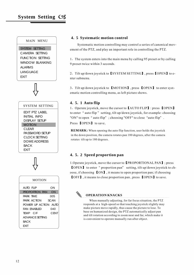
4. 5. 1
Systematic motion controlling may control a series of canonical mov-ement of the PTZ, and play an important role in controlling the PTZ.
The system enters into the main menu by calling 95 preset or by calling9 preset twice within 3 seconds.
Tilt up/down joystick to SYSTEM SETTING , press OPEN to e-nter submenu.
Tilt up/down joystick to MOTION , press OPEN to enter syst-ematic motion controlling menu, as left picture shows.
1 Operate joystick, move the cursor to AUTO FLIP : press OPENto enter auto flip setting, tilt up/down joystick, for example: choosing"ON" to open auto flip ; choosing "OFF" to close auto flip .
Press OPEN to save
Operate joystick, move the cursor to PROPORTIONAL PAN ; pressOPEN to enter proportion pan setting, tilt up/down joystick to ch-
oose, if choosing ON , it means to open proportion pan; if choosingOFF , it means to close proportion pan , press OPEN to save.
Auto flip
.
4. 5 Systematic motion control
4. 5. 2 Speed proportion pan
When manually adjusting, for far focus situation, the PTZresponds at a high-speed so that touching joystick slightly maymake picture move rapidly, thus cause the picture to lose. Tobase on humanized design, the PTZ automatically adjust panand tilt rotation according to zoom near and far, which make itis convenient to operate manually run after object.
OPERATION KNACKS
SYSTEM SETTING
EDIT PTZ LABELINITIAL INFODISPLAY SETUPMOTIONCLEARPASSWORD SETUPCLOCK SETTING
BACKEXIT
DOME ADDRESS
System Setting
12
MAIN MENU
SYSTEM SETTINGCAMERA SETTINGFUNCTION SETTINGWINDOW BLANKINGALARMSLANGUAGEEXIT
MOTION
AUTO FLIP ONPROPORTION PAN ONPARK TIME 005PARK ACTION SCANPOWER UP ACTION AUTO
BACKEXIT
FAN ENABLED 040TEMP C/F CENTADVANCE SETTING
REMARK: When opening the auto flip function, user holds the joystickin the down position, the camera rotates pan 180 degrees, after the camerarotates tilt up to 180 degrees.
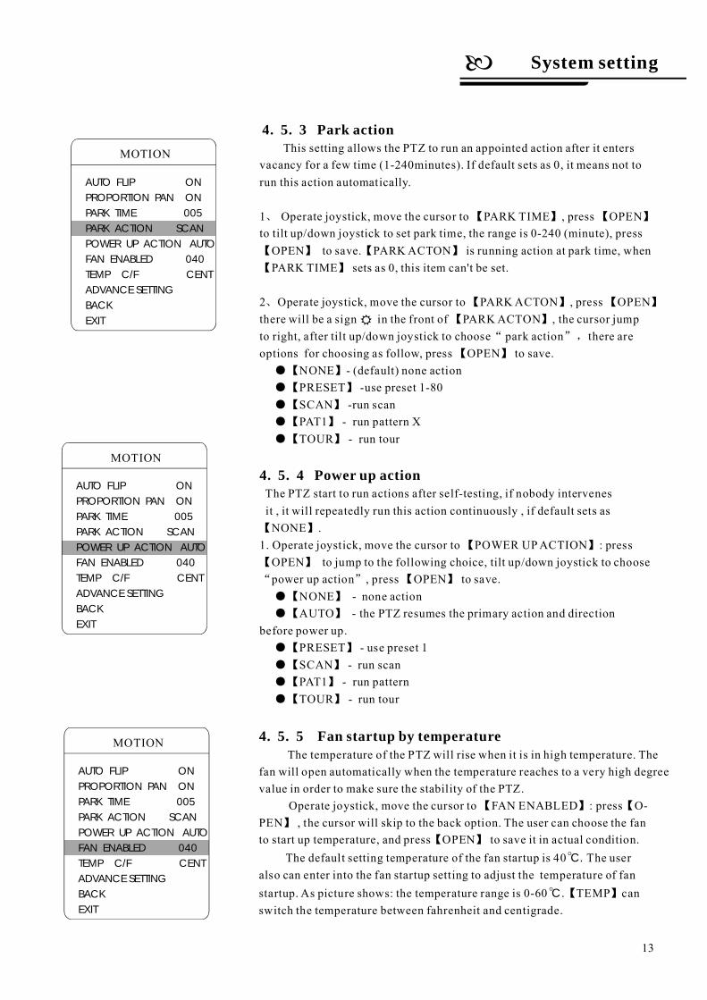
Power up action
This setting allows the PTZ to run an appointed action after it entersvacancy for a few time (1-240minutes). If default sets as 0, it means not torun this action automatically.
1 Operate joystick, move the cursor to PARK TIME , press OPENto tilt up/down joystick to set park time, the range is 0-240 (minute), pressOPEN to save. PARKACTON is running action at park time, whenPARK TIME sets as 0, this item can't be set.
2 Operate joystick, move the cursor to PARKACTON , press OPENthere will be a sign in the front of PARKACTON , the cursor jumpto right, after tilt up/down joystick to choose park action there areoptions for choosing as follow, press OPEN to save.
none actionuse preset 1-80
run scanrun pattern Xrun tour
The PTZ start to run actions after self-testing, if nobody intervenesit , it will repeatedly run this action continuously , if default sets asNONE .
1. Operate joystick, move the cursor to POWER UPACTION : pressOPEN to jump to the following choice, tilt up/down joystick to choosepower up action , press OPEN to save.
run scanrun patternrun tour
,
none actionthe PTZ resumes the primary action and direction
before power up.use preset 1
、 【 】 【 】
【 】 【 】
【 】
、 【 】 【 】
【 】
“ ”
【 】
【 】
【 】
【 】
【 】
【 】
【 】
【 】
【 】
“ ” 【 】
【 】
【 】
【 】
【 】
【 】
【 】
NONE - (default)PRESET -SCAN -PAT1 -TOUR -
NONE -AUTO -
PRESET -SCAN -PAT1 -TOUR -
●
●
●
●
●
●
●
●
●
●
●
4. 5. 4
4. 5. 5
【 】 【
】
【 】O
O
C.
C.【 】TEMP canswitch the temperature between fahrenheit and centigrade.
Fan startup by temperatureThe temperature of the PTZ will rise when it is in high temperature. The
fan will open automatically when the temperature reaches to a very high degreevalue in order to make sure the stability of the PTZ.
Operate joystick, move the cursor to FAN ENABLED : press O-PEN , the cursor will skip to the back option. The user can choose the fanto start up temperature, and press OPEN to save it in actual condition.
The default setting temperature of the fan startup is 40 The useralso can enter into the fan startup setting to adjust the temperature of fanstartup. As picture shows: the temperature range is 0-60
4. 5. 3 Park action
System setting
13
MOTION
AUTO FLIP ONPROPORTION PAN ONPARK TIME 005PARK ACTION SCANPOWER UP ACTION AUTO
BACKEXIT
FAN ENABLED 040TEMP C/F CENTADVANCE SETTING
MOTION
AUTO FLIP ONPROPORTION PAN ONPARK TIME 005PARK ACTION SCANPOWER UP ACTION AUTO
BACKEXIT
FAN ENABLED 040TEMP C/F CENTADVANCE SETTING
MOTION
AUTO FLIP ONPROPORTION PAN ONPARK TIME 005PARK ACTION SCANPOWER UP ACTION AUTO
BACKEXIT
FAN ENABLED 040TEMP C/F CENTADVANCE SETTING
LED 2
LED 1
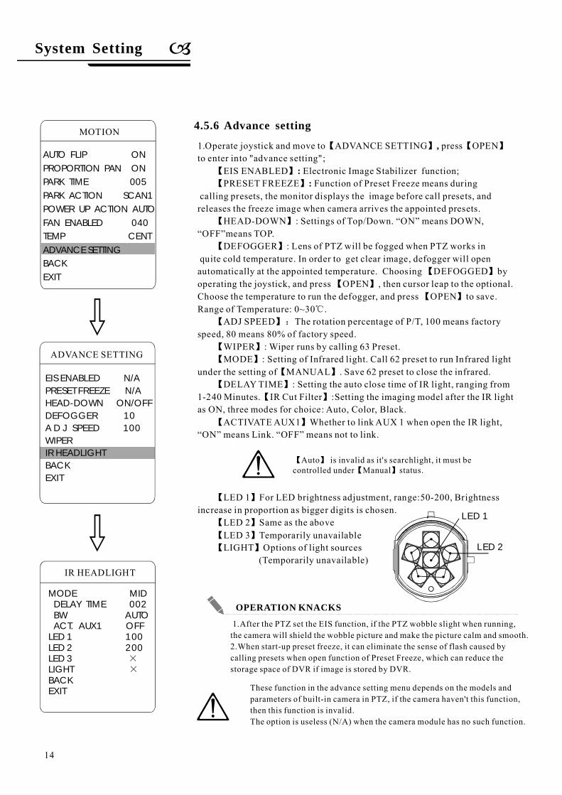
4.5.6 Advance setting
These function in the advance setting menu depends on the models andparameters of built-in camera in PTZ, if the camera haven't this function,then this function is invalid.The option is useless (N/A) when the camera module has no such function.
1.After the PTZ set the EIS function, if the PTZ wobble slight when running,the camera will shield the wobble picture and make the picture calm and smooth.2.When start-up preset freeze, it can eliminate the sense of flash caused bycalling presets when open function of Preset Freeze, which can reduce thestorage space of DVR if image is stored by DVR.
1.Operate joystick and move to ADVANCE SETTING press OPENto enter into "advance setting";
EIS ENABLED Electronic Image Stabilizer function;PRESET FREEZE Function of Preset Freeze means during
calling presets, the monitor displays the image before call presets, andreleases the freeze image when camera arrives the appointed presets.
HEAD-DOWN : Settings of Top/Down. N means DOWN,FF means TOP.
DEFOGGER : Lens of PTZ will be fogged when PTZ works inquite cold temperature. In order to get clear image, defogger will openautomatically at the appointed temperature. Choosing DEFOGGED byoperating the joystick, and press OPEN , then cursor leap to the optional.Choose the temperature to run the defogger, and press OPEN to save.Range of Temperature: 0~30 .
ADJ SPEED The rotation percentage of P/T, 100 means factoryspeed, 80 means 80% of factory speed.
WIPER : Wiper runs by calling 63 Preset.MODE : Setting of Infrared light. Call 62 preset to run Infrared light
under the setting of MANUAL . Save 62 preset to close the infrared.DELAYTIME : Setting the auto close time of IR light, ranging from
1-240 Minutes. IR Cut Filter :Setting the imaging model after the IR lightas ON, three modes for choice: Auto, Color, Black.
ACTIVATEAUX1 Whether to link AUX 1 when open the IR light,means not to link.
【 】 【 】
【 】
【 】
【 】
【 】
【 】
【 】
【 】
℃
【 】:
【 】
【 】
【 】
【 】
【 】
【 】
,
::
“O ”“O ”
“ON” means Link. “OFF”
LED 1 For LED brightness adjustment, range:50-200, Brightnessincrease in proportion as bigger digits is chosen.
LED 2 Same as the aboveLED 3 Temporarily unavailableLIGHT Options of light sources
(Temporarily unavailable)
【 】
【 】
【 】
【 】
System Setting
14
MOTION
AUTO FLIP ONPROPORTION PAN ONPARK TIME 005PARK ACTION SCAN1POWER UP ACTION AUTOFAN ENABLED 040TEMP CENT
BACKEXIT
ADVANCE SETTING
EIS ENABLED N/APRESET FREEZE N/A
IR HEADLIGHTBACKEXIT
ADVANCE SETTING
HEAD-DOWN ON/OFFDEFOGGER 10A D J SPEED 100WIPER
IR HEADLIGHT
MODE MID
BACKEXIT
DELAY TIME 002BW AUTOACT. AUX1 OFF
LED 1 100LED 2 200LED 3LIGHT
××
OPERATION KNACKS
【 】【 】
Auto is invalid as it's searchlight, it must becontrolled under Manual status.
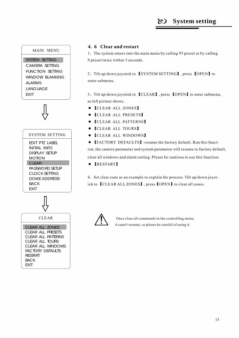
4. 6 Clear and restart1
2
3
CLEAR ALL PRESETS
CLEAR ALL PATTERNS
CLEAR ALL TOURS
CLEAR ALL WINDOWS
FACTORY DEFAULTS :
RESTART
4
、
、 【 】 【 】
、 【 】 【 】
● 【 】
【 】
【 】 【 】
● 【 】
●
●【 】
●【 】
●【 】
● 【 】
、
CLEAR ALL ZONES
The system enters into the main menu by calling 95 preset or by calling
9 preset twice within 3 seconds.
Tilt up/down joystick to SYSTEM SETTING , press OPEN to
enter submenu.
Tilt up/down joystick to CLEAR , press OPEN to enter submenu,
as left picture shows.
resume the factory default. Run this funct-
ion, the camera parameter and system parameter will resume to factory default,
clear all windows and alarm setting. Please be cautious to use this function
Set clear zone as an example to explain the process. Tilt up/down joyst-
ick to CLEARALL ZONES , press OPEN to clear all zones.
.
CLEAR
CLEAR ALL ZONESCLEAR ALL PRESETSCLEAR ALL PATTERNSCLEAR ALL TOURSCLEAR ALL WINDOWSFACTORY DEFAULTSRESTARTBACKEXIT
Once clear all commands in the controlling menu,
it cann't resume, so please be careful of using it.
SYSTEM SETTING
EDIT PTZ LABELINITIAL INFODISPLAY SETUPMOTIONCLEARPASSWORD SETUPCLOCK SETTING
BACKEXIT
DOME ADDRESS
System setting
15
MAIN MENU
SYSTEM SETTINGCAMERA SETTINGFUNCTION SETTINGWINDOW BLANKINGALARMSLANGUAGEEXIT
OLD PASSWORD ******
NEW PASSWORD ******
CONF PASSWORD ******
ENABLE PASSWORD OFF
BACK
EXIT
:
:
:
:
PASSWORD SETUP
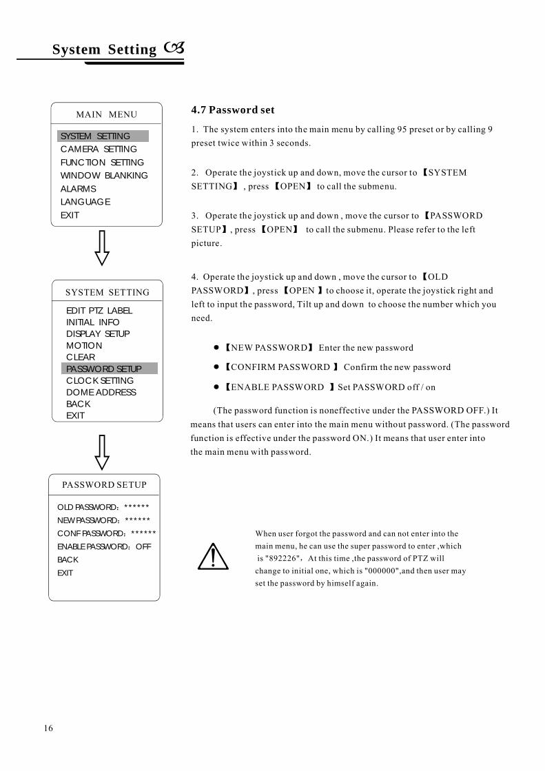
4.7 Password set
1. The system enters into the main menu by calling 95 preset or by calling 9preset twice within 3 seconds.
2. Operate the joystick up and down, move the cursor to SYSTEMSETTING , press OPEN to call the submenu.
【
】 【 】
3. Operate the joystick up and down , move the cursor to PASSWORDSETUP , press OPEN to call the submenu. Please refer to the leftpicture.
【
】 【 】
4. Operate the joystick up and down , move the cursor to OLDPASSWORD , press OPEN to choose it, operate the joystick right andleft to input the password, Tilt up and down to choose the number which youneed.
【
】 【 】
NEW PASSWORD Enter the new password●【 】
CONFIRM PASSWORD Confirm the new password●【 】
ENABLE PASSWORD Set PASSWORD off / on●【 】
(The password function is noneffective under the PASSWORD OFF.) Itmeans that users can enter into the main menu without password. (The passwordfunction is effective under the password ON.) It means that user enter intothe main menu with password.
When user forgot the password and can not enter into themain menu, he can use the super password to enter ,whichis "892226" At this time ,the password of PTZ willchange to initial one, which is "000000",and then user mayset the password by himself again.
,
SYSTEM SETTING
EDIT PTZ LABELINITIAL INFODISPLAY SETUPMOTIONCLEARPASSWORD SETUPCLOCK SETTING
BACKEXIT
DOME ADDRESS
System Setting
16
MAIN MENU
SYSTEM SETTINGCAMERA SETTINGFUNCTION SETTINGWINDOW BLANKINGALARMSLANGUAGEEXIT
TIME 03:20:18
DATE 07:10:10
DAY WED
BACK
EXIT
CLOCK SETTING
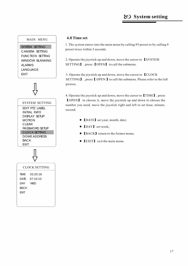
4.8 Time set
1. The system enters into the main menu by calling 95 preset or by calling 9preset twice within 3 seconds.
2. Operate the joystick up and down, move the cursor to SYSTEMSETTING , press OPEN to call the submenu.
【
】 【 】
3. Operate the joystick up and down, move the cursor to CLOCKSETTING , press OPEN to call the submenu. Please refer to the leftpicture.
【
】 【 】
4. Operate the joystick up and down, move the cursor to TIME , pressOPEN to choose it, move the joystick up and down to choose the
number you need, move the joystick right and left to set hour, minute,second.
【 】
【 】
DATE set year, month, date;●【 】
DAY set week;●【 】
BACK return to the former menu;●【 】
EXIT exit the main menu.●【 】
SYSTEM SETTING
EDIT PTZ LABELINITIAL INFODISPLAY SETUPMOTIONCLEARPASSWORD SETUPCLOCK SETTING
BACKEXIT
DOME ADDRESS
System setting
17
MAIN MENU
SYSTEM SETTINGCAMERA SETTINGFUNCTION SETTINGWINDOW BLANKINGALARMSLANGUAGEEXIT
1.
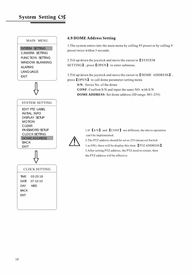
2.Tilt up/down the joystick and move the cursor to SYSTEMSETTING , press OPEN to enter submenu.
3.Tilt up/down the joystick and move the cursor to DOME ADDRESS ,press OPEN to call dome parameter setting menu. : Series No. of the dome
: Confirm S/N and input the same NO. with S/N: Set dome address (ID range: 001-255)
The system enters into the main menu by calling 95 preset or by calling 9preset twice within 3 seconds.
【
】 【 】
【 】
【 】
S/NCONFDOME ADDRESS
TIME 03:20:18
DATE 07:10:10
DAY WED
BACK
EXIT
SYSTEM SETTING
EDIT PTZ LABELINITIAL INFODISPLAY SETUPMOTIONCLEARPASSWORD SETUPCLOCK SETTINGDOME ADDRESSBACKEXIT
CLOCK SETTING
1.If S/N and CONF are different, the above operation
can't be implemented.
2.The PTZ address should be set as 255 (mean set Switch
1 as ON), there will be display this item PTZADDRESS
3.After setting PTZ address, the PTZ need to restart, then
the PTZ address will be effective.
【 】 【 】
【 】
4.9 DOME Address Setting
System Setting
18
MAIN MENU
SYSTEM SETTINGCAMERA SETTINGFUNCTION SETTINGWINDOW BLANKINGALARMSLANGUAGEEXIT
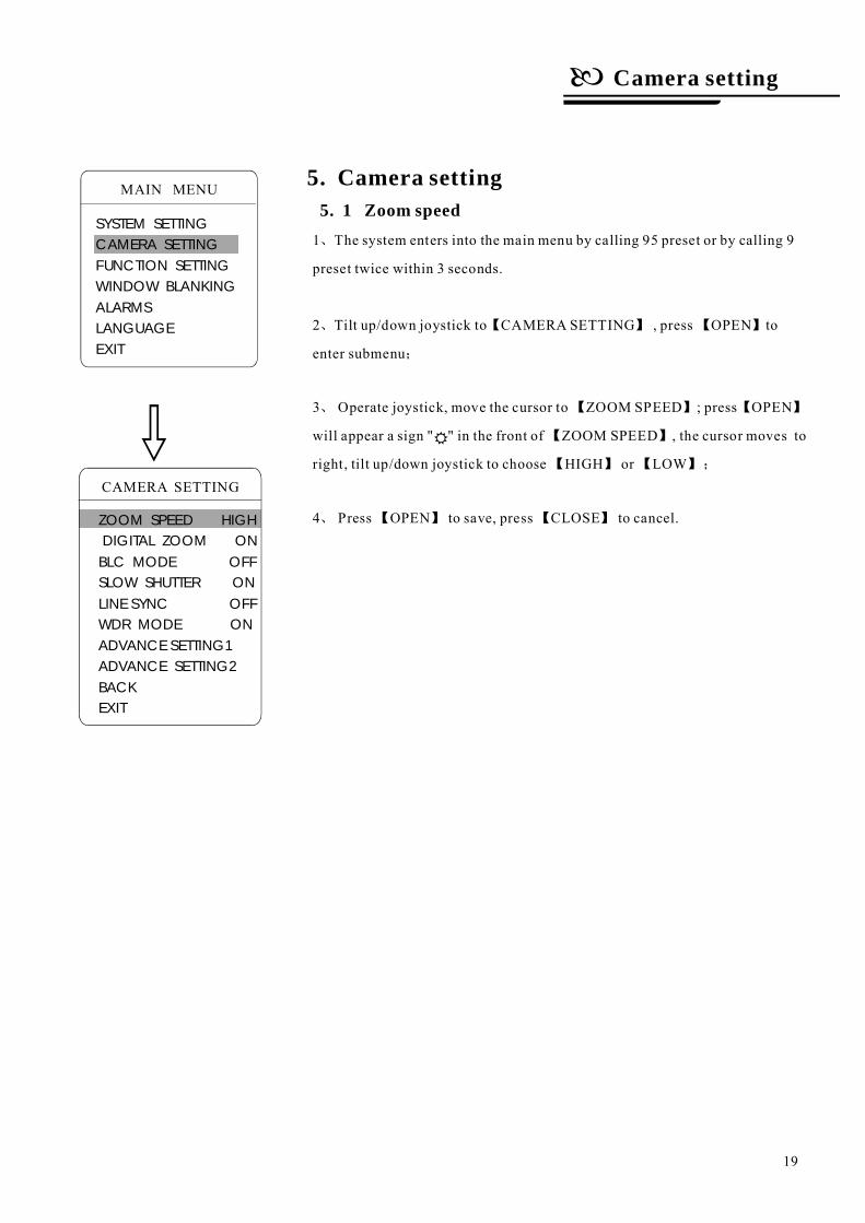
5. Camera setting5. 1 Zoom speed1
2
3
4
、
、
;
、
、
【 】 【 】
【 】 【 】
【 】
【 】 【 】
【 】 【 】
The system enters into the main menu by calling 95 preset or by calling 9
preset twice within 3 seconds.
Tilt up/down joystick to CAMERA SETTING , press OPEN to
enter submenu
Operate joystick, move the cursor to ZOOM SPEED ; press OPEN
will appear a sign " " in the front of ZOOM SPEED , the cursor moves to
right, tilt up/down joystick to choose HIGH or LOW
Press OPEN to save, press CLOSE to cancel.
;
Camera setting
19
MAIN MENU
SYSTEM SETTINGCAMERA SETTINGFUNCTION SETTINGWINDOW BLANKINGALARMSLANGUAGEEXIT
CAMERA SETTING
ZOOM SPEED HIGHDIGITAL ZOOM ONBLC MODE OFFSLOW SHUTTER ONLINE SYNC OFFWDR MODE ONADVANCE SETTING1ADVANCE SETTING2BACKEXIT
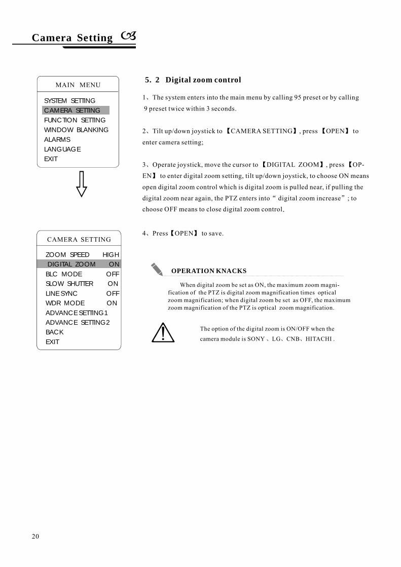
5. 2 Digital zoom control
1
2
3
4
、
、 【 】 【 】
、 【 】 【
】
“ ”
、 【 】
The system enters into the main menu by calling 95 preset or by calling
9 preset twice within 3 seconds.
Tilt up/down joystick to CAMERA SETTING , press OPEN to
enter camera setting;
Operate joystick, move the cursor to DIGITAL ZOOM , press OP-
EN to enter digital zoom setting, tilt up/down joystick, to choose ON means
open digital zoom control which is digital zoom is pulled near, if pulling the
digital zoom near again, the PTZ enters into digital zoom increase ; tochoose OFF means to close digital zoom control
Press OPEN to save.
.
The option of the digital zoom is ON/OFF when the
camera module is SONY LG CNB .、 、 、HITACHI
When digital zoom be set as ON, the maximum zoom magni-fication of the PTZ is digital zoom magnification times opticalzoom magnification; when digital zoom be set as OFF, the maximumzoom magnification of the PTZ is optical zoom magnification.
Camera Setting
20
MAIN MENU
SYSTEM SETTINGCAMERA SETTINGFUNCTION SETTINGWINDOW BLANKINGALARMSLANGUAGEEXIT
CAMERA SETTING
ZOOM SPEED HIGHDIGITAL ZOOM ONBLC MODE OFFSLOW SHUTTER ONLINE SYNC OFFWDR MODE ONADVANCE SETTING1ADVANCE SETTING2BACKEXIT
OPERATION KNACKS
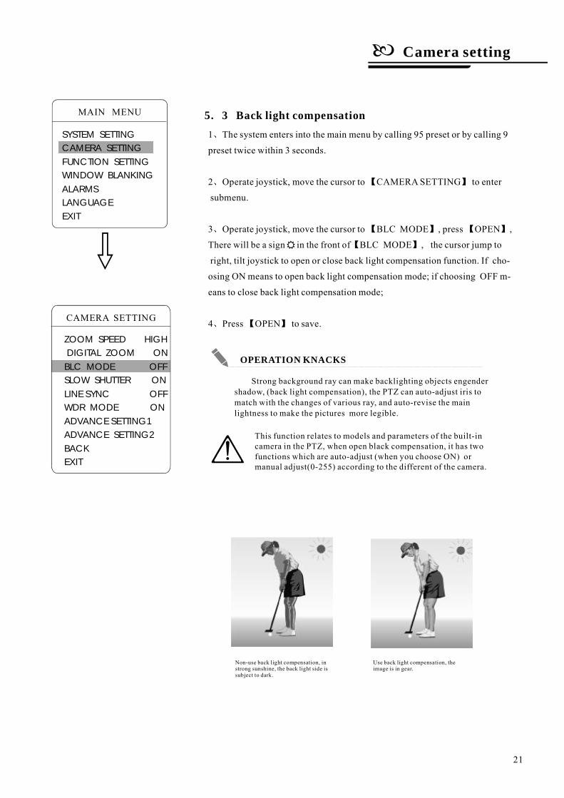
5. 3 Back light compensation
Non-use back light compensation, instrong sunshine, the back light side issubject to dark.
Use back light compensation, theimage is in gear.
1
2
3
4
、
、
、
、
【 】
【 】 【 】
【 】
【 】
The system enters into the main menu by calling 95 preset or by calling 9
preset twice within 3 seconds.
Operate joystick, move the cursor to CAMERASETTING to enter
submenu.
Operate joystick, move the cursor to BLC MODE , press OPEN ,
There will be a sign in the front of BLC MODE , the cursor jump to
right, tilt joystick to open or close back light compensation function. If cho-
osing ON means to open back light compensation mode; if choosing OFF m-
eans to close back light compensation mode;
Press OPEN to save.
Strong background ray can make backlighting objects engendershadow, (back light compensation), the PTZ can auto-adjust iris tomatch with the changes of various ray, and auto-revise the mainlightness to make the pictures more legible.
This function relates to models and parameters of the built-incamera in the PTZ, when open black compensation, it has twofunctions which are auto-adjust (when you choose ON) ormanual adjust(0-255) according to the different of the camera.
Camera setting
21
MAIN MENU
SYSTEM SETTINGCAMERA SETTINGFUNCTION SETTINGWINDOW BLANKINGALARMSLANGUAGEEXIT
CAMERA SETTING
ZOOM SPEED HIGHDIGITAL ZOOM ONBLC MODE OFFSLOW SHUTTER ONLINE SYNC OFFWDR MODE ONADVANCE SETTING1ADVANCE SETTING2BACKEXIT
OPERATION KNACKS
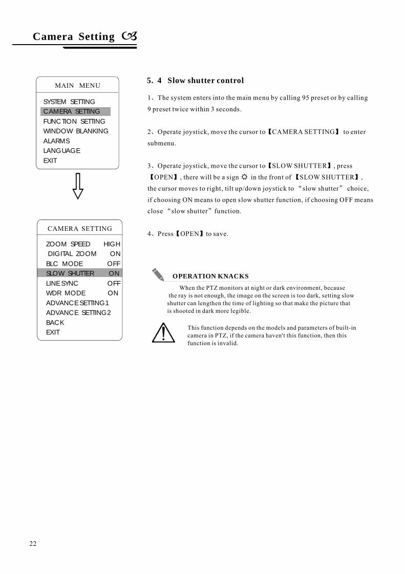
5. 4 Slow shutter control
1
2
3
4
、
、
、
“ ”
“ ”
、
【 】
【 】
【 】 【 】
【 】
The system enters into the main menu by calling 95 preset or by calling
9 preset twice within 3 seconds.
Operate joystick, move the cursor to CAMERA SETTING to enter
submenu.
Operate joystick, move the cursor to SLOW SHUTTER , press
OPEN , there will be a sign in the front of SLOW SHUTTER ,
the cursor moves to right, tilt up/down joystick to slow shutter choice,
if choosing ON means to open slow shutter function, if choosing OFF means
close slow shutter function.
Press OPEN to save.
When the PTZ monitors at night or dark environment, becausethe ray is not enough, the image on the screen is too dark, setting slowshutter can lengthen the time of lighting so that make the picture thatis shooted in dark more legible.
This function depends on the models and parameters of built-incamera in PTZ, if the camera haven't this function, then thisfunction is invalid.
Camera Setting
22
MAIN MENU
SYSTEM SETTINGCAMERA SETTINGFUNCTION SETTINGWINDOW BLANKINGALARMSLANGUAGEEXIT
CAMERA SETTING
ZOOM SPEED HIGHDIGITAL ZOOM ONBLC MODE OFFSLOW SHUTTER ONLINE SYNC OFFWDR MODE ONADVANCE SETTING1ADVANCE SETTING2BACKEXIT
OPERATION KNACKS
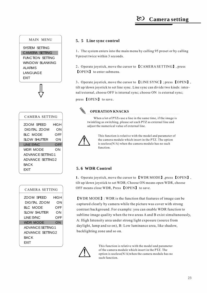
5. 5 Line sync control
1
2
3
、
、 【 】
【 】
、 【 】 【 】
【 】
、 【 】 【 】
【 】
【 】
1
The system enters into the main menu by calling 95 preset or by calling9 preset twice within 3 seconds.
Operate joystick, move the cursor to CAMERASETTING , pressOPEN to enter submenu.
Operate joystick, move the cursor to LINE SYNC ; press OPEN ,tilt up/down joystick to set line sync. Line sync can divide two kinds: inter-nal/external, choose OFF is internal sync; choose ON is external sync;
press OPEN to save
Operate joystick, move the cursor to WDR MODE ,press OPEN ,tilt up/down joystick to set WDR; Choose ON means open WDR, chooseOFF means close WDR, Press OPEN to save.
.
WDR MODE : WDR is the function that features of image can becaptured clearly by camera while the picture was cover with strongcontrast background. For example: you can enable WDR function tosublime image quality when the two areas A and B exist simultaneously,A: High Intensity area under strong light exposure (source fromdaylight, lamp and so on), B: Low luminance area, like shadow,backlighting zone and so on.
When a lot of PTZs use a line in the same time, if the image istwinkling as switching, please set each PTZ as external line andadjust the numerical value of external line.
This function is relative with the model and parameter ofthe camera module which insert in the PTZ. The optionis useless(N/A) when the camera module has no suchfunction.
This function is relative with the model and parameterof the camera module which insert in the PTZ. Theoption is useless(N/A)when the camera module has nosuch function.
5. 6 WDR Control
Camera setting
23
MAIN MENU
SYSTEM SETTINGCAMERA SETTINGFUNCTION SETTINGWINDOW BLANKINGALARMSLANGUAGEEXIT
CAMERA SETTING
ZOOM SPEED HIGHDIGITAL ZOOM ONBLC MODE OFFSLOW SHUTTER ONLINE SYNC OFFWDR MODE ONADVANCE SETTING1ADVANCE SETTING2BACKEXIT
CAMERA SETTING
ZOOM SPEED HIGHDIGITAL ZOOM ONBLC MODE OFFSLOW SHUTTER ONLINE SYNC OFFWDR MODE ONADVANCE SETTING1ADVANCE SETTING2BACKEXIT
OPERATION KNACKS
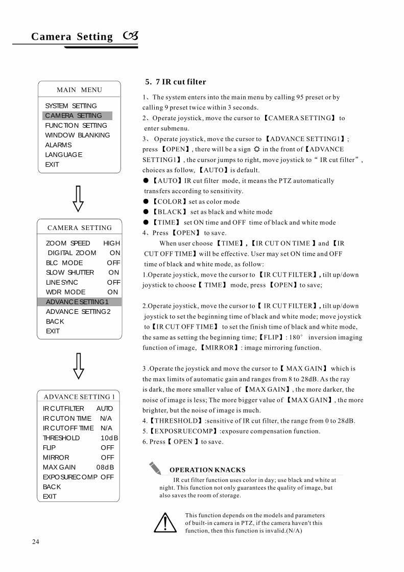
5. 7 IR cut filter
1
2
3
AUTO IR cut filter
COLORBLACK
4
、
、 【 】
、 【 】
【 】 【
】 “ ”
【 】
●【 】
●【 】
●【 】
●【 】
、 【 】
【 】 【 】 【
】
【 】
【 】 【 】
【 】
【 】
【 】
【 】
【 】
【 】
【 】
【 】
【 】
【 】
The system enters into the main menu by calling 95 preset or bycalling 9 preset twice within 3 seconds.
Operate joystick, move the cursor to CAMERA SETTING toenter submenu.
Operate joystick, move the cursor to ADVANCE SETTING1 ;press OPEN , there will be a sign in the front of ADVANCESETTING1 , the cursor jumps to right, move joystick to IR cut filter ,choices as follow, AUTO is default.
mode, it means the PTZ automaticallytransfers according to sensitivity.
set as color modeset as black and white mode
TIME set ON time and OFF time of black and white modePress OPEN to save.When user choose TIME IR CUT ON TIME and IR
CUT OFF TIME will be effective. User may set ON time and OFFtime of black and white mode, as follow:1.Operate joystick, move the cursor to IR CUT FILTER tilt up/downjoystick to choose TIME mode, press OPEN to save;
2.Operate joystick, move the cursor to IR CUT FILTER tilt up/downjoystick to set the beginning time of black and white mode; move joystickto IR CUT OFF TIME to set the finish time of black and white mode,the same as setting the beginning time; FLIP : 180 inversion imagingfunction of image, MIRROR : image mirroring function.
3 .Operate the joystick and move the cursor to MAX GAIN which isthe max limits of automatic gain and ranges from 8 to 28dB. As the rayis dark, the more smaller value of MAX GAIN , the more darker, thenoise of image is less; The more bigger value of MAX GAIN , the morebrighter, but the noise of image is much.4. THRESHOLD :sensitive of IR cut filter, the range from 0 to 28dB.5. EXPOSRUECOMP :exposure compensation function.6. Press OPEN to save.
,
,
,
°
CAMERA SETTING
ZOOM SPEED HIGHDIGITAL ZOOM ONBLC MODE OFFSLOW SHUTTER ONLINE SYNC OFFWDR MODE ONADVANCE SETTING1ADVANCE SETTING2BACKEXIT
IR cut filter function uses color in day; use black and white atnight. This function not only guarantees the quality of image, butalso saves the room of storage.
This function depends on the models and parametersof built-in camera in PTZ, if the camera haven't thisfunction, then this function is invalid.(N/A)
Camera Setting
24
MAIN MENU
SYSTEM SETTINGCAMERA SETTINGFUNCTION SETTINGWINDOW BLANKINGALARMSLANGUAGEEXIT
IR CUT FILTER AUTOIR CUT ON TIME N/AIR CUT OFF TIME N/ATHRESHOLD 10dBFLIP OFFMIRROR OFFMAX GAIN 08dBEXPOSURECOMP OFFBACKEXIT
ADVANCE SETTING 1
OPERATION KNACKS
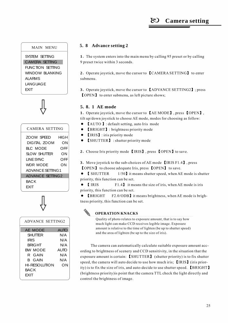
5. 8 Advance setting 2
1
2
3
、
、
、
、
】
【 】
【 】
【 】
【 】
【 】 【 】
、 【 】 【 】
【 】
【 】 【 】
【 】
【 】
【 】
5. . 1
●
●
●
●
●
●
●
【 】
【 】
【
【 】
、
【 】
【 】
AUTO : default:
::
SHUTTER 1/50
IRIS F1.4
BRIGHT F2.0/ODB
BRIGHTIRISSHUTTER
The system enters into the main menu by calling 95 preset or by calling9 preset twice within 3 seconds.
Choose Iris priority mode IRIS , press OPEN to save.
Operate joystick, move the cursor to CAMERA SETTING to entersubmenu.
Operate joystick, move the cursor to ADVANCE SETTING2 ; pressOPEN to enter submenu, as left picture shows;
Operate joystick, move the cursor to AE MODE , press OPEN ,tilt up/down joystick to choose AE mode, modes for choosing as follow:
8 AE mode1
setting, auto Iris modebrightness priority mode
iris priority modeshutter priority mode
Move joystick to the sub-choices of AE mode IRIS F1.4 , pressOPEN to choose adequate Iris, press OPEN to save.
it means shutter speed, when AE mode is shutterpriority, this function can be set.
it means the size of iris, whenAE mode is irispriority, this function can be set.
it means brightness, whenAE mode is brigh-tness priority, this function can be set.
The camera can automatically calculate suitable exposure amount acc-ording to brightness of scenery and CCD sensitivity, in the situation that theexposure amount is certain: SHUTTER (shutter priority) is to fix shutterspeed, the camera will auto decide to use how much iris; IRIS (iris prior-ity) is to fix the size of iris, and auto-decide to use shutter speed. BRIGHT(brightness priority)is point that the camera TTL check the light directly andcontrol the brightness of image.
2
3
ADVANCE SETTING2
AE MODE AUTOSHUTTER N/AIRISBRIGHT
BW MODE AUTOR GAINB GAIN
HI-RESOLUTION ONBACKEXIT
N/AN/A
N/AN/A
Quality of photo relates to exposure amount, that is to say howmuch light can make CCD receives legible image. Exposureamount is relative to the time of lighten (be up to shutter speed)and the area of lighten (be up to the size of iris).
Camera setting
25
MAIN MENU
SYSTEM SETTINGCAMERA SETTINGFUNCTION SETTINGWINDOW BLANKINGALARMSLANGUAGEEXIT
CAMERA SETTING
ZOOM SPEED HIGHDIGITAL ZOOM ONBLC MODE OFFSLOW SHUTTER ONLINE SYNC OFFWDR MODE ONADVANCE SETTING1ADVANCE SETTING2BACKEXIT
OPERATION KNACKS
5. 8. 2【 】 【 】
【 】 【 】 【 】
【 】 【 】
、
“
”
、 【 】
【 】
【 】
【 】
【 】 【 】
【 】
【 】
【 】
1
2
R GAIN t
B GAIN
●
●
【 】
【 】
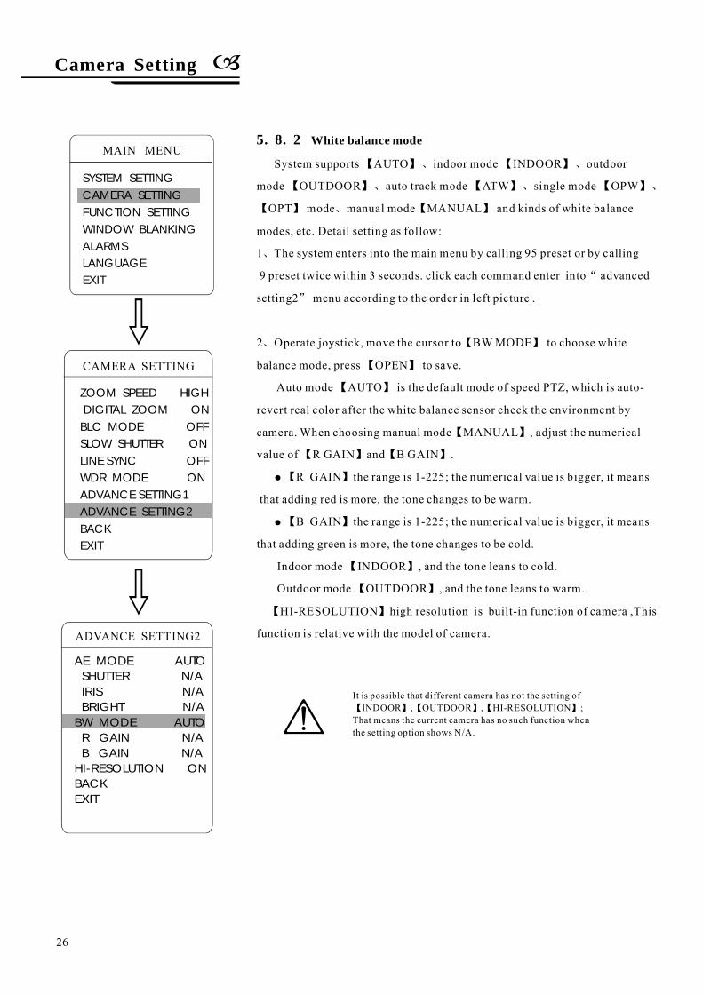
White balance mode
System supports AUTO indoor mode INDOOR outdoor
mode OUTDOOR auto track mode ATW single mode OPW
OPT mode manual mode MANUAL and kinds of white balance
modes, etc. Detail setting as follow:
The system enters into the main menu by calling 95 preset or by calling
9 preset twice within 3 seconds. click each command enter into advanced
setting2 menu according to the order in left picture .
Operate joystick, move the cursor to BWMODE to choose white
balance mode, press OPEN to save.
Auto mode AUTO is the default mode of speed PTZ, which is auto-
revert real color after the white balance sensor check the environment by
camera. When choosing manual mode MANUAL , adjust the numerical
value of R GAIN and B GAIN .
、 、
、 、 、
、
he range is 1-225; the numerical value is bigger, it means
that adding red is more, the tone changes to be warm.
the range is 1-225; the numerical value is bigger, it means
that adding green is more, the tone changes to be cold.
Indoor mode INDOOR , and the tone leans to cold.
Outdoor mode OUTDOOR , and the tone leans to warm.
HI-RESOLUTION high resolution is built-in function of camera ,This
function is relative with the model of camera.ADVANCE SETTING2
AE MODE AUTOSHUTTER N/AIRISBRIGHT
BW MODE AUTOR GAINB GAIN
HI-RESOLUTION ONBACKEXIT
N/AN/A
N/AN/A
It is possible that different camera has not the setting ofINDOOR , OUTDOOR , HI-RESOLUTION ;
That means the current camera has no such function whenthe setting option shows N/A.
【 】【 】【 】
Camera Setting
26
MAIN MENU
SYSTEM SETTINGCAMERA SETTINGFUNCTION SETTINGWINDOW BLANKINGALARMSLANGUAGEEXIT
CAMERA SETTING
ZOOM SPEED HIGHDIGITAL ZOOM ONBLC MODE OFFSLOW SHUTTER ONLINE SYNC OFFWDR MODE ONADVANCE SETTING1ADVANCE SETTING2BACKEXIT
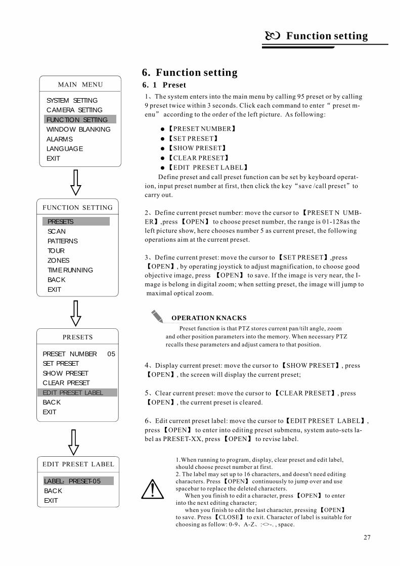
6. 1 Preset6. Function setting
1
Define
、
“
”
、 【
】 【 】
、 【 】
【 】
【 】
、 【 】
【 】
、 【 】
【 】
、 【 】
【 】
【 】
5
6
The system enters into the main menu by calling 95 preset or by calling9 preset twice within 3 seconds. Click each command to enter preset m-enu according to the order of the left picture. As following:
preset and call preset function can be set by keyboard operat-ion, input preset number at first, then click the key save /call preset tocarry out.
2 Define current preset number: move the cursor to PRESET N UMB-ER ,press OPEN to choose preset number, the range is 01-128as theleft picture show, here chooses number 5 as current preset, the followingoperations aim at the current preset.
3 Define current preset: move the cursor to SET PRESET ,pressOPEN , by operating joystick to adjust magnification, to choose good
objective image, press OPEN to save. If the image is very near, the I-mage is belong in digital zoom; when setting preset, the image will jump tomaximal optical zoom.
Display current preset: move the cursor to SHOW PRESET , pressOPEN , the screen will display the current preset;
Clear current preset: move the cursor to CLEAR PRESET , pressOPEN , the current preset is cleared.
Edit current preset label: move the cursor to EDIT PRESET LABEL ,press OPEN to enter into editing preset submenu, system auto-sets la-bel as PRESET-XX, press OPEN to revise label.
“ ”
4
FUNCTION SETTING
PRESETSSCANPATTERNSTOURZONESTIME RUNNINGBACKEXIT
PRESETS
PRESET NUMBER 05SET PRESETSHOW PRESETCLEAR PRESETEDIT PRESET LABELBACKEXIT
EDIT PRESET LABEL
EDIT PRESET LABEL
LABEL PRESET-05BACKEXIT
:
Preset function is that PTZ stores current pan/tilt angle, zoomand other position parameters into the memory. When necessary PTZrecalls these parameters and adjust camera to that position.
1.When running to program, display, clear preset and edit label,should choose preset number at first.2. The label may set up to 16 characters, and doesn't need editingcharacters. Press OPEN continuously to jump over and usespacebar to replace the deleted characters.
When you finish to edit a character, press OPEN to enterinto the next editing character;
when you finish to edit the last character, pressing OPENto save. Press CLOSE to exit. Character of label is suitable forchoosing as follow: 0-9 A-Z :<>-. , space.、 、
【 】
【 】
【 】【 】
●
●
●
●
●
PRESET NUMBERSET PRESETSHOW PRESETCLEAR PRESETEDIT PRESET LABEL
【 】
【 】
【 】
【 】
【 】
Function setting
27
MAIN MENU
SYSTEM SETTINGCAMERA SETTINGFUNCTION SETTINGWINDOW BLANKINGALARMSLANGUAGEEXIT
OPERATION KNACKS
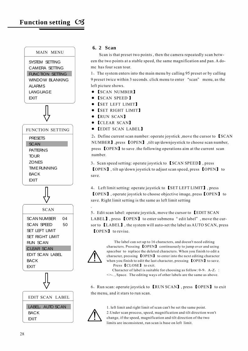
6. 2 Scan
1
SCAN SPEEDSET LEFT LIMITSET RIGHT LIMITRUN SCANCLEAR SCANEDIT SCAN LABEL
3
、
“ ”
】
】
、
、
、
“ ”
、
●【 】
●【 】
●【 】
●【
●【
●【 】
●【 】
【 】
【 】 【 】
【 】
【 】 【 】
【
】 【 】
【 】
【 】
【 】 【 】
SCAN NUMBER
Scan is that preset two points , then the camera repeatedly scan betw-een the two points at a stable speed, the same magnification and pan. A do-me has four scan tour.
The system enters into the main menu by calling 95 preset or by calling9 preset twice within 3 seconds. click menu to enter scan menu, as theleft picture shows.
Scan speed setting: operate joystick to SCAN SPEED , pressOPEN , tilt up/down joystick to adjust scan speed, press OPEN to
save.
4 Left limit setting: operate joystick to SET LEFT LIMIT , pressOPEN , operate joystick to choose objective image, press OPEN to
save. Right limit setting is the same as left limit setting.5 Edit scan label: operate joystick, move the cursor to EDIT SCANLABEL , press OPEN to enter submenu edit label , move the cur-sor to LABEL , the system will auto-set the label as AUTO SCAN, press
OPEN to revise.
6 Run scan: operate joystick to RUN SCAN , press OPEN to exitthe menu, and it stars to run scan.
SCAN
SCAN NUMBER 04SCAN SPEED 50SET LEFT LIMITSET RIGHT LIMITRUN SCANCLEAR SCANEDIT SCAN LABELBACKEXIT
EDIT SCAN LABEL
LABEL AUTO SCANBACKEXIT
:
FUNCTION SETTING
PRESETSSCANPATTERNSTOURZONESTIME RUNNINGBACKEXIT
The label can set up to 16 characters, and doesn't need editingcharacters. Pressing OPEN continuously to jump over and usingspacebar to replace the deleted characters. When you finish to edit acharacter, pressing OPEN to enter into the next editing characterwhen you finish to edit the last character, pressing OPEN to save.
Press CLOSE to exit.Character of label is suitable for choosing as follow: 0-9 A-Z :
<>-. , Space. The editing ways of other labels are the same as above.、 、
【 】
【 】
【 】
【 】
1. left limit and right limit of scan can't be set the same point.2.Under scan process, speed, magnification and tilt direction won'tchange, if the speed, magnification and tilt direction of the twolimits are inconsistent, run scan is base on left limit.
2 Define current scan number: operate joystick ,move the cursor to SCANNUMBER ,press OPEN ,tilt up/downjoystick to choose scan number,press OPEN to save .the following operations aim at the current scannumber.
、 【
】 【 】
【 】
Function setting
28
MAIN MENU
SYSTEM SETTINGCAMERA SETTINGFUNCTION SETTINGWINDOW BLANKINGALARMSLANGUAGEEXIT
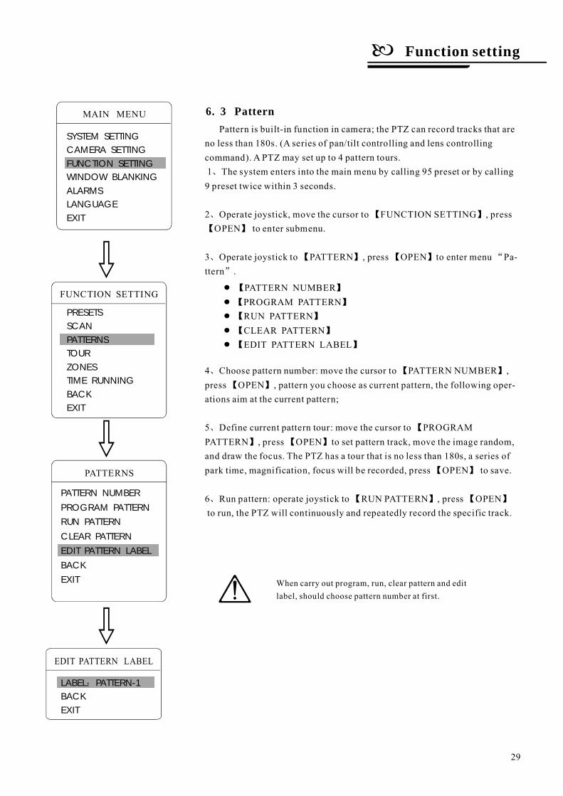
6. 3 Pattern
2
3
4
5
6
、
、 【 】
【 】
、 【 】 【 】 “
”
、 【 】
【 】
、 【
】 【 】
【 】
、 【 】 【 】
Pattern is built-in function in camera; the PTZ can record tracks that areno less than 180s. (A series of pan/tilt controlling and lens controllingcommand). A PTZ may set up to 4 pattern tours.1 The system enters into the main menu by calling 95 preset or by calling9 preset twice within 3 seconds.
Operate joystick, move the cursor to FUNCTION SETTING , pressOPEN to enter submenu.
Operate joystick to PATTERN , press OPEN to enter menu Pa-ttern .
Choose pattern number: move the cursor to PATTERN NUMBER ,press OPEN , pattern you choose as current pattern, the following oper-ations aim at the current pattern;
Define current pattern tour: move the cursor to PROGRAMPATTERN , press OPEN to set pattern track, move the image random,and draw the focus. The PTZ has a tour that is no less than 180s, a series ofpark time, magnification, focus will be recorded, press OPEN to save.
Run pattern: operate joystick to RUN PATTERN , press OPENto run, the PTZ will continuously and repeatedly record the specific track.
PATTERNS
PATTERN NUMBER
PROGRAM PATTERN
RUN PATTERN
CLEAR PATTERN
EDIT PATTERN LABEL
BACK
EXIT
EDIT PATTERN LABEL
LABEL PATTERN-1BACKEXIT
:
FUNCTION SETTING
PRESETSSCANPATTERNSTOURZONESTIME RUNNINGBACKEXIT
When carry out program, run, clear pattern and editlabel, should choose pattern number at first.
● 【 】
●【 】
●【 】
●【 】
●【 】
PATTERN NUMBERPROGRAM PATTERNRUN PATTERNCLEAR PATTERNEDIT PATTERN LABEL
Function setting
29
MAIN MENU
SYSTEM SETTINGCAMERA SETTINGFUNCTION SETTINGWINDOW BLANKINGALARMSLANGUAGEEXIT
FUNCTION SETTING
PRESETSSCANPATTERNSTOURZONESTIME RUNNINGBACKEXIT
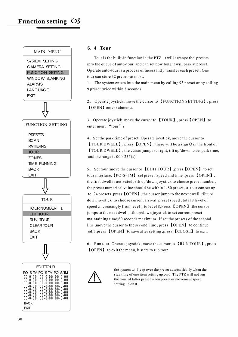
Tour is the built-in function in the PTZ, it will arrange the presetsinto the queue of auto-tour, and can set how long it will park at preset.Operate auto-tour is a process of incessantly transfer each preset. Onetour can store 32 presets at most.
The system enters into the main menu by calling 95 preset or by calling9 preset twice within 3 seconds.
Operate joystick, move the cursor to FUNCTION SETTING , pressOPEN enter submenu.
Operate joystick, move the cursor to TOUR , press OPEN toenter menu tour
Set the park time of preset: Operate joystick, move the cursor toTOUR DWELL , press OPEN , there will be a sign in the front ofTOUR DWELL , the cursor jumps to right, tilt up/down to set park time,
and the range is 000-255(s)
Run tour: Operate joystick, move the cursor to RUN TOUR , pressOPEN to exit the menu, it stars to run tour.
1
2
3
4
5 Set tour :move the cursor to EDIT TOUR ,press OPEN to settour interface, PO-S-TM set preset ,speed and time ,press OPEN ,the first dwell is activated , tilt up/down joystick to choose preset number,the preset numerical value should be within 1-80 preset , a tour can set upto 24 presets .press OPEN ,the cursor jump to the next dwell ,tilt up/down joystick to choose current arrival preset speed , total 8 level ofspeed ,increasingly from level 1 to level 8;Press OPEN ,the cursorjumps to the next dwell , tilt up/down joystick to set current presetmaintaining time,60 seconds maximum . If set the presets of the secondline ,move the cursor to the second line , press OPEN to continueedit .press OPEN to save after setting ,press CLOSE to exit.
6
、
、 【 】
【 】
、 【 】 【 】
“ ”;
、
【 】 【 】
【 】
、 【 】 【 】
【 】 【 】
【 】
【 】
【 】
【 】 【 】
、 【 】
【 】
6. 4 Tour
TOUR
TOUR NUMBER 1EDIT TOURRUN TOURCLEAR TOURBACKEXIT
EDIT TOUR
00-0-00 00-0-00 00-0-0000-0-00 00-0-00 00-0-0000-0-00 00-0-00 00-0-0000-0-00 00-0-00 00-0-0000-0-00 00-0-00 00-0-0000-0-00 00-0-00 00-0-0000-0-00 00-0-00 00-0-0000-0-00 00-0-00 00-0-00
PO-S-TM PO-S-TM PO-S-TM
BACKEXIT
the system will leap over the preset automatically when thestay time of one item setting up on 0; The PTZ will not runthe tour of latter preset when preset or movement speedsetting up on 0 .
Function setting
30
MAIN MENU
SYSTEM SETTINGCAMERA SETTINGFUNCTION SETTINGWINDOW BLANKINGALARMSLANGUAGEEXIT
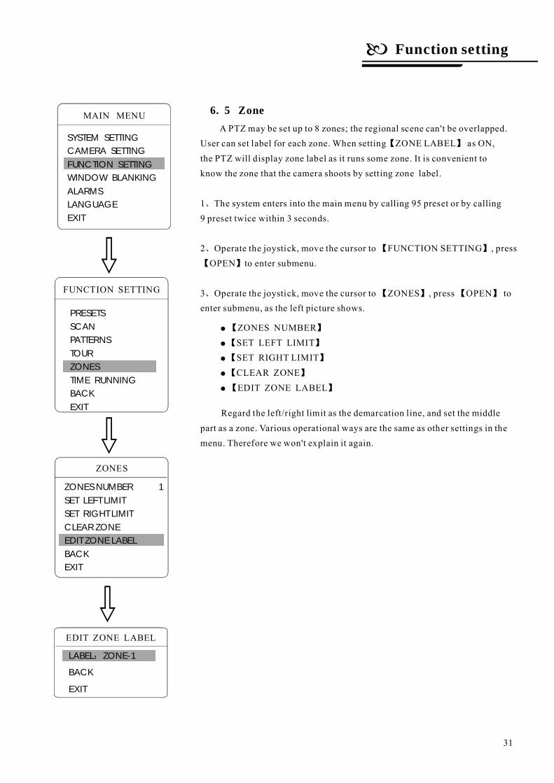
6. 5 ZoneA PTZ may be set up to 8 zones; the regional scene can't be overlapped.
User can set label for each zone. When setting ZONE LABEL as ON,the PTZ will display zone label as it runs some zone. It is convenient toknow the zone that the camera shoots by setting zone label.
The system enters into the main menu by calling 95 preset or by calling9 preset twice within 3 seconds.
Operate the joystick, move the cursor to FUNCTION SETTING , pressOPEN to enter submenu.
Operate the joystick, move the cursor to ZONES , press OPEN toenter submenu, as the left picture shows.
Regard the left/right limit as the demarcation line, and set the middlepart as a zone. Various operational ways are the same as other settings in themenu. Therefore we won't explain it again.
【 】
、
、 【 】
【 】
、 【 】 【 】
1
2
3FUNCTION SETTING
PRESETSSCANPATTERNSTOURZONESTIME RUNNINGBACKEXIT
ZONES
EDIT ZONE LABEL
LABEL ZONE-1
BACK
EXIT
:
ZONES NUMBER 1SET LEFT LIMITSET RIGHT LIMITCLEAR ZONEEDIT ZONE LABELBACKEXIT
●
●
●
●
●
【 】
【 】
【 】
【 】
【 】
ZONES NUMBERSET LEFT LIMITSET RIGHT LIMITCLEAR ZONEEDIT ZONE LABEL
Function setting
31
MAIN MENU
SYSTEM SETTINGCAMERA SETTINGFUNCTION SETTINGWINDOW BLANKINGALARMSLANGUAGEEXIT
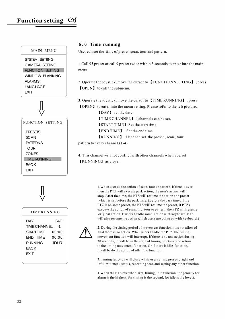
User can set the time of preset, scan, tour and pattern.
1.Call 95 preset or call 9 preset twice within 3 seconds to enter into the mainmenu.
2. Operate the joystick, move the cursor to FUNCTION SETTING , pressOPEN to call the submenu.
3. Operate the joystick, move the cursor to TIME RUNNING , pressOPEN to enter into the menu setting. Please refer to the left picture.
DAY set the dateTIME CHANNEL 4 channels can be set.START TIME Set the start timeEND TIME Set the end timeRUNNING User can set the preset , scan , tour,
pattern to every channel.(1-4)
4. This channel will not conflict with other channels when you setRUNNING as close.
【 】
【 】
【 】
【 】
【 】
【 】
【 】
【 】
【 】
【 】
1.When user do the action of scan, tour or pattern, if time is over,then the PTZ will execute park action, the user's action willstop. After the time, the PTZ will resume the action and presetwhich is set before the park time. (Before the park time, if thePTZ is on some preset, the PTZ will resume the preset, if PTZsexecute the action of scanning, tour or pattern, the PTZ will resumeoriginal action. If users handle some action with keyboard, PTZwill also resume the action which users are going on with keyboard.)
2. During the timing period of movement function, it is not allowedthat there is no action. When users handle the PTZ, the timingmovement function will interrupt. If there is no any action during30 seconds, it will be in the state of timing function, and returnto the timing movement function. Or if there is idle function,it will be do the action of idle time function.
3. Timing function will close while user setting presets, right andleft limit, menu status, recording scan and setting any other function.
4.When the PTZ execute alarm, timing, idle function, the priority foralarm is the highest, for timing is the second, for idle is the lovest.
FUNCTION SETTING
PRESETSSCANPATTERNSTOURZONESTIME RUNNINGBACKEXIT
DAY SATTIME CHANNEL 1START TIME 00:00END TIME 00:00RUNNING TOUR1BACKEXIT
TIME RUNNING
6 . 6 Time running
Function setting
32
MAIN MENU
SYSTEM SETTINGCAMERA SETTINGFUNCTION SETTINGWINDOW BLANKINGALARMSLANGUAGEEXIT
7. Privacy zone masking
Privacy zone masking
Privacy zone masking
WINDOW NUMBER
EDIT WINDOWENABLE WINDOW
CLEAR WINDOW
.
1
2
3
、
、
“ ”
【 】
【 】 ;
【 】
【 】
、
【 】 【 】
【 】 【
】
【 】
【 】
【 】
●
●
●
●
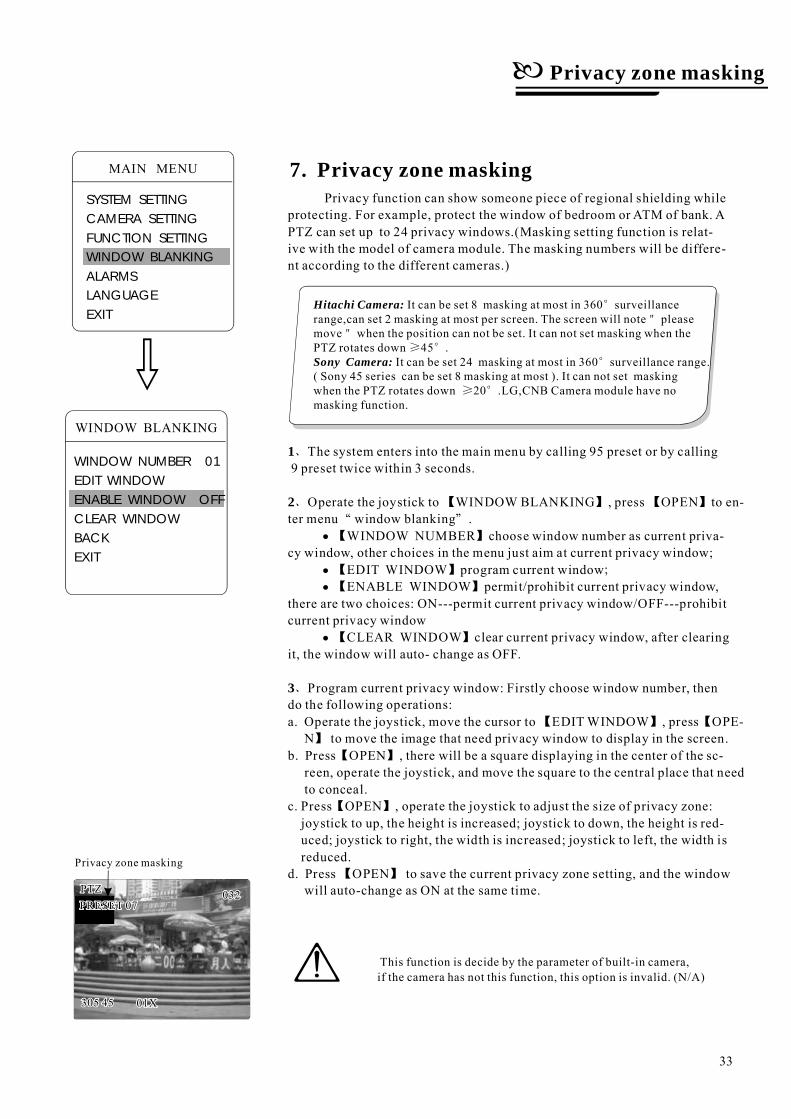
Privacy function can show someone piece of regional shielding whileprotecting. For example, protect the window of bedroom or ATM of bank. APTZ can set up to 24 privacy windows.(Masking setting function is relat-ive with the model of camera module. The masking numbers will be differe-nt according to the different cameras.)
Operate the joystick to WINDOW BLANKING , press OPEN to en-ter menu window blanking .
choose window number as current priva-cy window, other choices in the menu just aim at current privacy window;
program current windowpermit/prohibit current privacy window,
there are two choices: ON---permit current privacy window/OFF---prohibitcurrent privacy window
clear current privacy window, after clearingit, the window will auto- change as OFF.
Program current privacy window: Firstly choose window number, thendo the following operations:a. Operate the joystick, move the cursor to EDITWINDOW , press OPE-
N to move the image that need privacy window to display in the screen.b Press OPEN , there will be a square displaying in the center of the sc-
reen, operate the joystick, and move the square to the central place that needto conceal.
c. Press OPEN , operate the joystick to adjust the size of privacy zone:joystick to up, the height is increased; joystick to down, the height is red-uced; joystick to right, the width is increased; joystick to left, the width isreduced.
d. Press OPEN to save the current privacy zone setting, and the windowwill auto-change as ON at the same time.
The system enters into the main menu by calling 95 preset or by calling9 preset twice within 3 seconds.
WINDOW BLANKING
WINDOW NUMBER 01EDIT WINDOWENABLE WINDOW OFFCLEAR WINDOWBACKEXIT
Hitachi Camera:
Sony Camera:
It can be set 8 masking at most in 360 surveillancerange,can set 2 masking at most per screen. The screen will note pleasemove when the position can not be set. It can not set masking when thePTZ rotates down 45 .
It can be set 24 masking at most in 360 surveillance range.( Sony 45 series can be set 8 masking at most ). It can not set maskingwhen the PTZ rotates down 20 .LG,CNB Camera module have nomasking function.
°"
"≥ °
°
≥ °
This function is decide by the parameter of built-in camera,if the camera has not this function, this option is invalid. (N/A)
33
MAIN MENU
SYSTEM SETTINGCAMERA SETTINGFUNCTION SETTINGWINDOW BLANKINGALARMSLANGUAGEEXIT
8. Alarm function
Alarm Function
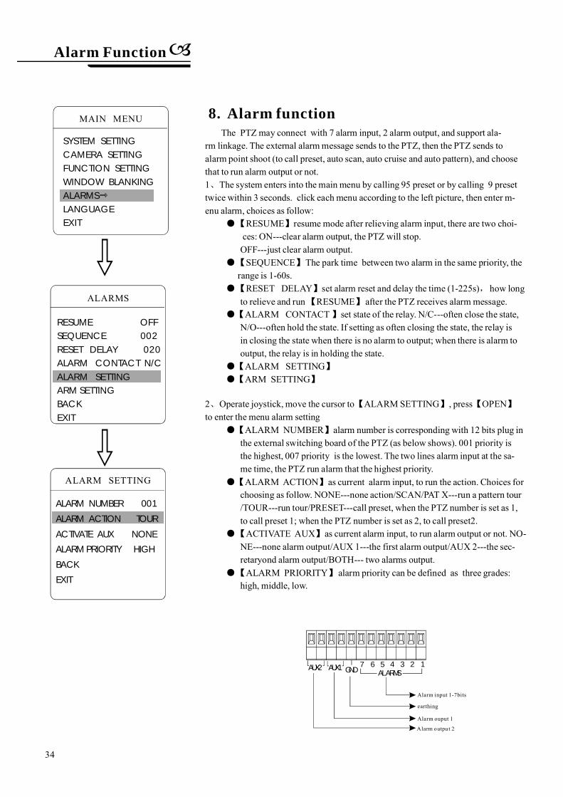
AUX2 GND1234567
ALARMSAUX1
earthing
Alarm input 1-7bits
Alarm ouput 1
Alarm output 2
The PTZmay connect with 7 alarm input, 2 alarm output, and support ala-rm linkage. The external alarmmessage sends to the PTZ, then the PTZ sends toalarm point shoot (to call preset, auto scan, auto cruise and auto pattern), and choosethat to run alarm output or not.
The system enters into the main menu by calling 95 preset or by calling 9 presettwice within 3 seconds. click each menu according to the left picture, then enter m-enu alarm, choices as follow:
alarm number is corresponding with 12 bits plug inthe external switching board of the PTZ (as below shows). 001 priority isthe highest, 007 priority is the lowest. The two lines alarm input at the sa-me time, the PTZ run alarm that the highest priority.
as current alarm input, to run the action. Choices forchoosing as follow. NONE---none action/SCAN/PAT X---run a pattern tour/TOUR---run tour/PRESET---call preset, when the PTZ number is set as 1,to call preset 1; when the PTZ number is set as 2, to call preset2.
as current alarm input, to run alarm output or not. NO-NE---none alarm output/AUX 1---the first alarm output/AUX 2---the sec-retaryond alarm output/BOTH--- two alarms output.ALARM PRIORITY alarm priority can be defined as three grades:
high, middle, low.
resume mode after relieving alarm input, there are two choi-ces: ON---clear alarm output, the PTZ will stop.OFF---just clear alarm output.SEQUENCE The park time between two alarm in the same priority, the
range is 1-60s.set alarm reset and delay the time (1-225s) how long
to relieve and run RESUME after the PTZ receives alarm message.set state of the relay. N/C---often close the state,
N/O---often hold the state. If setting as often closing the state, the relay isin closing the state when there is no alarm to output; when there is alarm tooutput, the relay is in holding the state.AL
to ALARMSETTING , press OPENto enter the menu alarm setting
,
1
ALARM CONTACT
ARM SETTINGARM SETTING
2 Operate joystick, move the cursor
ALARM NUMBER
ALARM ACTION
ACTIVATE AUX
、
●【 】
【 】
●【 】
●【 】
【 】 【 】
●【 】
●【 】
●【 】
●【 】
●【 】
●【 】
●【 】
、
RESUME
RESET DELAYALARMS
RESUME OFFSEQUENCE 002RESET DELAY 020ALARM CONTACT N/CALARM SETTINGARM SETTINGBACKEXIT
ALARM SETTING
ALARM NUMBER 001
ALARM ACTION TOUR
ACTIVATE AUX NONE
ALARM PRIORITY HIGH
BACK
EXIT
34
MAIN MENU
SYSTEM SETTINGCAMERA SETTINGFUNCTION SETTINGWINDOW BLANKINGALARMSLANGUAGEEXIT
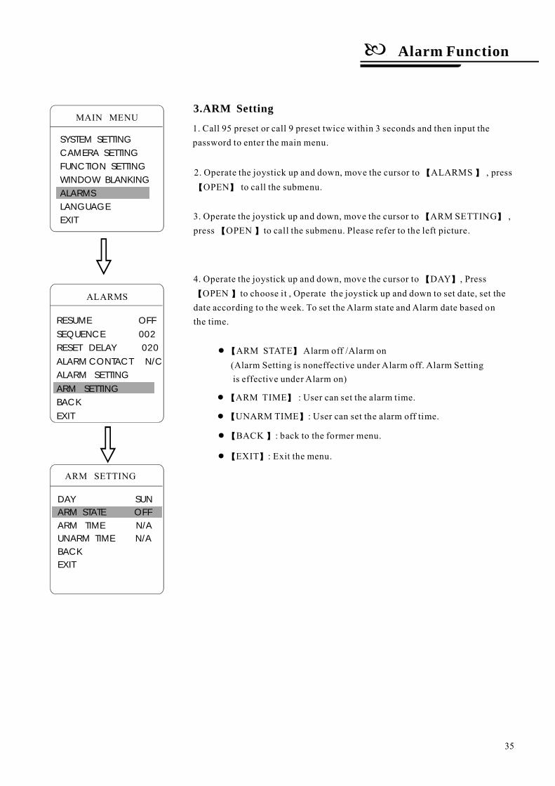
3.ARM Setting
1. Call 95 preset or call 9 preset twice within 3 seconds and then input thepassword to enter the main menu.
2. Operate the joystick up and down, move the cursor to ALARMS , pressOPEN to call the submenu.
【 】【 】
3. Operate the joystick up and down, move the cursor to ARM SETTING ,press OPEN to call the submenu. Please refer to the left picture.
【 】【 】
4. Operate the joystick up and down, move the cursor to DAY , PressOPEN to choose it , Operate the joystick up and down to set date, set the
date according to the week. To set the Alarm state and Alarm date based onthe time.
【 】【 】
ARM STATE Alarm off /Alarm on●【 】(Alarm Setting is under Alarm off. Alarm Settingnoneffectiveis effective under Alarm on)
ARM TIME : User can set the alarm time.●【 】
UNARM TIME : User can set the alarm off time.●【 】
BACK : back to the former menu.●【 】
EXIT : Exit the menu.●【 】
Alarm Function
35
ARM SETTING
DAY SUNARM STATE OFFARM TIME N/AUNARM TIME N/ABACKEXIT
ALARMS
RESUME OFFSEQUENCE 002RESET DELAY 020ALARM CONTACT N/CALARM SETTINGARM SETTINGBACKEXIT
MAIN MENU
SYSTEM SETTINGCAMERA SETTINGFUNCTION SETTINGWINDOW BLANKINGALARMSLANGUAGEEXIT
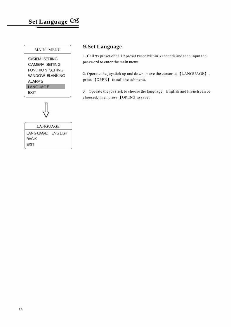
MAIN MENU
SYSTEM SETTINGCAMERA SETTINGFUNCTION SETTINGWINDOW BLANKINGALARMSLANGUAGEEXIT
LANGUAGE ENGLISHBACKEXIT
LANGUAGE
9.Set Language1. Call 95 preset or call 9 preset twice within 3 seconds and then input thepassword to enter the main menu.
2. Operate the joystick up and down, move the cursor to LANGUAGE ,press OPEN to call the submenu.
press OPEN to save
【 】【 】
【 】3 Operate the joystick to choose the language English and French can bechoosed, Then、 ,
。
Set Language
36
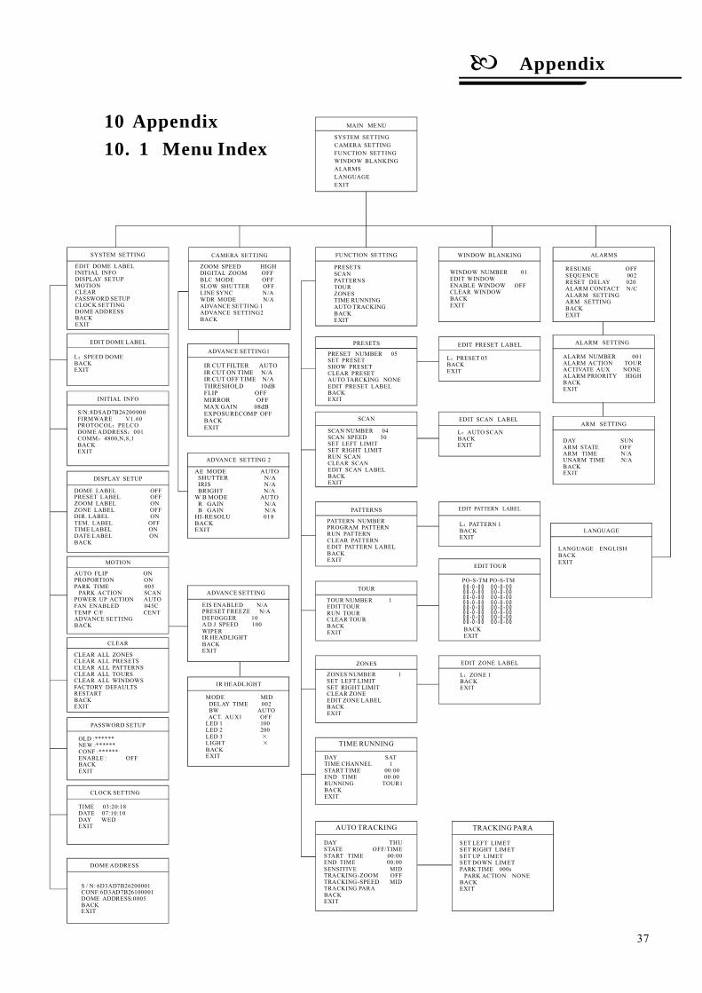
10. 1 Menu Index
Appendix
37
10 Appendix
ALARMS
RESUME OFFSEQUENCE 002RESET DELAY 020ALARM CONTACT N/CALARM SETTINGARM SETTINGBACKEXIT
MAIN MENU
SYSTEM SETTINGCAMERA SETTINGFUNCTION SETTINGWINDOW BLANKINGALARMS
EXITLANGUAGE
CAMERA SETTING
ZOOM SPEED HIGHDIGITAL ZOOM OFFBLC MODE OFFSLOW SHUTTER OFFLINE SYNC N/AWDR MODE N/AADVANCE SETTING 1ADVANCE SETTING2BACK
FUNCTION SETTING
PRESETSSCANPATTERNSTOURZONESTIME RUNNINGAUTO TRACKINGBACKEXIT
EDIT DOME LABEL
L SPEED DOMEBACKEXIT
:
INITIAL INFO
DISPLAY SETUP
DOME LABEL OFFPRESET LABEL OFFZOOM LABEL ONZONE LABEL OFFDIR. LABEL ON
LABEL OFFTIME LABEL ONDATE LABEL ONBACK
TEM.
MOTION
AUTO FLIP ONPROPORTION ONPARK TIME 005PARK ACTION SCAN
POWER UP ACTION AUTOFAN ENABLED 045CTEMP C/F CENTADVANCE SETTINGBACK
CLEAR
CLEAR ALL ZONESCLEAR ALL PRESETSCLEAR ALL PATTERNSCLEAR ALL TOURSCLEAR ALL WINDOWSFACTORY DEFAULTSRESTARTBACKEXIT
OLD :******NEW :******CONF :******ENABLE : OFFBACKEXIT
PASSWORD SETUP
TIME 03:20:18DATE 07:10:10DAY WEDEXIT
CLOCK SETTING
ADVANCE SETTING1
WINDOW BLANKING
WINDOW NUMBER 01EDIT WINDOWENABLE WINDOW OFFCLEAR WINDOWBACKEXIT
PRESET NUMBER 05SET PRESETSHOW PRESETCLEAR PRESETAUTO TARCKING NONEEDIT PRESET LABELBACKEXIT
PRESETS EDIT PRESET LABEL
L PRESET 05BACKEXIT
:
SCAN
SCAN NUMBER 04SCAN SPEED 50SET LEFT LIMITSET RIGHT LIMITRUN SCANCLEAR SCANEDIT SCAN LABELBACKEXIT
EDIT SCAN LABEL
L AUTO SCANBACKEXIT
:
PATTERNS
PATTERN NUMBERPROGRAM PATTERNRUN PATTERNCLEAR PATTERNEDIT PATTERN LABELBACKEXIT
TOUR
TOUR NUMBER 1EDIT TOURRUN TOURCLEAR TOURBACKEXIT
EDIT PATTERN LABEL
L PATTERN 1BACKEXIT
:
EDIT TOUR
00-0-00 00-0-0000-0-00 00-0-0000-0-00 00-0-0000-0-00 00-0-0000-0-00 00-0-0000-0-00 00-0-0000-0-00 00-0-0000-0-00 00-0-00
PO-S-TM PO-S-TM
BACKEXIT
EDIT ZONE LABEL
L ZONE 1BACKEXIT
:
ZONES
ZONES NUMBER 1SET LEFT LIMITSET RIGHT LIMITCLEAR ZONEEDIT ZONE LABELBACKEXIT
DAY SATTIME CHANNEL 1START TIME 00:00END TIME 00:00RUNNING TOUR1BACKEXIT
TIME RUNNING
EDIT DOME LABELINITIAL INFODISPLAY SETUPMOTIONCLEARPASSWORD SETUPCLOCK SETTINGDOMEADDRESSBACKEXIT
SYSTEM SETTING
ALARM SETTING
ALARM NUMBER 001ALARM ACTION TOURACTIVATE AUX NONEALARM PRIORITY HIGHBACKEXIT
ARM SETTING
DAY SUNARM STATE OFFARM TIME N/AUNARM TIME N/ABACKEXIT
ADVANCE SETTING
AUTO TRACKING
DAY THUSTATE OFF/TIMESTART TIME 00:00END TIME 00:00SENSITIVE MIDTRACKING-ZOOM OFFTRACKING-SPEED MIDTRACKING PARABACKEXIT
SET LEFT LIMETSET RIGHT LIMETSET UP LIMETSET DOWN LIMETPARK TIME 000sPARK ACTION NONE
BACKEXIT
TRACKING PARA
DOMEADDRESS
ADVANCE SETTING 2
AE MODE AUTOSHUTTER N/AIRIS N/ABRIGHT N/AB MODE AUTO
R GAIN N/AB GAIN N/AHI-RESOLU 018BACKEXIT
W
EIS ENABLED N/APRESET FREEZE N/ADEFOGGER 10AD J SPEED 100WIPERIR HEADLIGHTBACKEXIT
S/N:8DSAD7B26200000FIRMWARE V1.60PROTOCOL PELCODOME ADDRESS 001COMM 4800,N,8,1BACKEXIT
::
:
S / N: 6D3AD7B26200001CONF:6D3AD7B26100001DOME ADDRESS:0005BACKEXIT
IR CUT FILTER AUTOIR CUT ON TIME N/AIR CUT OFF TIME N/ATHRESHOLD 10dBFLIP OFFMIRROR OFFMAX GAIN 08dBEXPOSURECOMP OFFBACKEXIT
LANGUAGE
LANGUAGE ENGLISHBACKEXIT
IR HEADLIGHT
MODE MIDDELAY TIME 002BW AUTOACT. AUX1 OFFLED 1 100LED 2 200LED 3LIGHTBACKEXIT
××
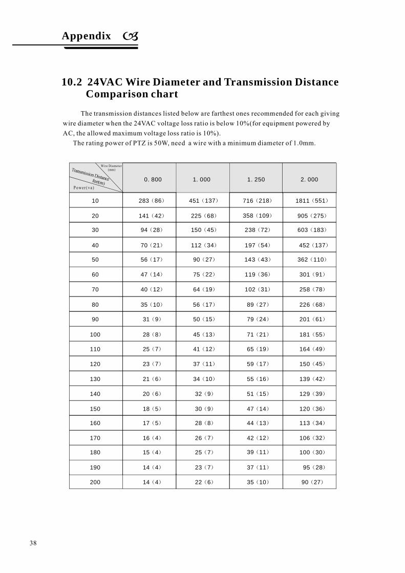
10
20
30
40
50
60
70
80
90
100
110
120
130
140
150
160
170
180
190
200
283(86)
141(42)
94(28)
70(21)
56(17)
47(14)
40(12)
35(10)
31(9)
28(8)
25(7)
23(7)
21(6)
20(6)
18(5)
17(5)
16(4)
15(4)
14(4)
14(4)
0.800 1.000 1.250 2.000
451(137)
225(68)
150(45)
112(34)
90(27)
75(22)
64(19)
56(17)
50(15)
45(13)
41(12)
37(11)
34(10)
32(9)
30(9)
28(8)
26(7)
25(7)
23(7)
22(6)
716(218)
358(109)
238(72)
197(54)
143(43)
119(36)
102(31)
89(27)
79(24)
71(21)
65(19)
59(17)
55(16)
51(15)
47(14)
44(13)
42(12)
39(11)
37(11)
35(10)
1811(551)
905(275)
603(183)
452(137)
362(110)
301(91)
258(78)
226(68)
201(61)
181(55)
164(49)
150(45)
139(42)
129(39)
120(36)
113(34)
106(32)
100(30)
95(28)
90(27)
The transmission distances listed below are farthest ones recommended for each givingwire diameter when the 24VAC voltage loss ratio is below 10%(for equipment powered byAC, the allowed maximum voltage loss ratio is 10%).
The rating power of PTZ is 50W, need a wire with a minimum diameter of 1.0mm.
10.2 24VAC Wire Diameter and Transmission DistanceComparison chart
Wire Diameter(mm)
P ow e r ( v a )
38
Appendix
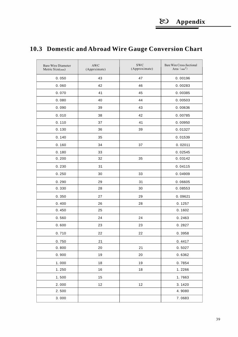
10.3 Domestic and Abroad Wire Gauge Conversion Chart
BareWire DiameterMetric Size( )mm (Apprximate)
AWC SWC(Approximate)
BareWire Cross-SectionalArea( )mm2
0.050
0.060
0.200
0.070
0.230
0.080
0.250
0.710
0.090
0.290
0.750
0.010
0.330
0.800
0.110
0.350
0.900
0.130
0.400
1.000
0.140
0.450
1.250
0.160
0.560
1.500
0.180
0.600
2.000
43
42
32
41
31
40
30
22
39
29
21
38
28
20
37
27
19
36
26
18
35
25
16
34
24
15
33
23
12
47
46
35
45
44
33
22
43
31
42
30
21
41
29
20
39
28
19
18
37
24
23
12
0.00196
0.00283
0.03142
0.00385
0.04115
0.00503
0.04909
0.3958
0.00636
0.06605
0.4417
0.00785
0.08553
0.5027
0.00950
0.09621
0.6362
0.01327
0.1257
0.7854
0.01539
0.1602
1.2266
0.02011
0.2463
1.7663
0.02545
0.2827
3.1420
2.500
3.000
4.9080
7.0683
39
Appendix

Ø
Ø
Ø
Characteristics of Rs485 Bus
Transmission distances of Rs485 Bus
Connection and termination resistor
As specified by Rs485 standard, Rs485 Bus is ofhalf-duplexed data transmission cables with chara-cteristic impedance as 120 . The maximum loadcapacity is 32 unit loads (including main controllerand controlled equipment.)
When user selects the 0.56mm(24AWG)twist-ed pair wires as data transmission cable, the maxi-mum theoretical transmitting distance are as foll-ows:
If user selects thinner cables, or installs the PTZin an environment with strong electromagneticinterference, or connects lots of equipment to theRs485 Bus, the maximum transmitting distance w-ill be decreased. To increase the maximum transm-itting distance, do the contrary.
The Rs485 standards require a daisy-chain Conn-ection between the equipment. There must be ter-mination resistors with 120 (as the picture 10-2.1).Please refer to picture 10-2.2 for simple connection.D should not exceed 7m.
Ω
Ω
“ ”
10. 4 Rs485 Bus Basic Knowledge
120Ω1# 2# 3# 4# 32#
Picture 10-4.1
120Ω
120Ω1# 2# 3# 4# 32#
D
A+
B-
A+ B-
Picture 10-4.2
120Ω
2400BPS
4800BPS
9600BPS
1800m
1200m
800m
Baud rate Max distance
19200BPS 600m
Picture10-4.3
Ø The connection of 120 termination resistor:Ω
40
Connection mode for 120 resistance of equipmentterminal. Setting connection of terminal resistance120 in the base cover. (Refer to Picture 10-4.3):Default of factory (No.8 digit of SW2 is seton code switch)No.8 digit of SW2 is set oncode switch if needed to connect 120 resistance.
“OFF”“ON”
Ω
Ω
Sw1Sw2
Setting of 120 resistanceΩ
Appendix
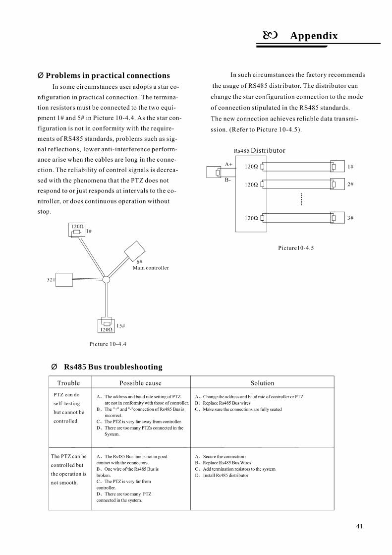
Ø Problems in practical connectionsIn some circumstances user adopts a star co-
nfiguration in practical connection. The termina-tion resistors must be connected to the two equi-pment 1# and 5# in Picture 10-4.4. As the star con-figuration is not in conformity with the require-ments of RS485 standards, problems such as sig-nal reflections, lower anti-interference perform-ance arise when the cables are long in the conne-ction. The reliability of control signals is decrea-sed with the phenomena that the PTZ does notrespond to or just responds at intervals to the co-ntroller, or does continuous operation withoutstop.
Trouble Possible cause Solution
PTZ can do
self-testing
but cannot be
controlled
The PTZ can be
controlled but
the operation isnot smooth.
A Secure the connectionB Replace Rs485 BusWiresC Add termination resistors to the systemD Install Rs485 distributor
、 ;
、
、
、
Ø Rs485 Bus troubleshooting
Rs485Distributor
B-
1#
2#
3#
120Ω
120Ω
120Ω
A+
1#
32#
15#
6#Main controller
Picture 10-4.4
Picture10-4.5
120Ω
120Ω
A The Rs485 Bus line is not in goodcontact with the connectors.B One wire of the Rs485 Bus isbroken.C The PTZ is very far fromcontroller.D There are toomany PTZconnected in the system.
、
、
、
、
A The address and baud rate setting of PTZare not in conformity with those of controller.
B The "+" and "-"connection of Rs485 Bus isincorrect.
C The PTZ is very far away from controller.D There are toomany PTZs connected in the
System.
、
、
、
、
A Change the address and baud rate of controller or PTZB Replace Rs485 Bus wiresC Make sure the connections are fully seated
、
、
、
In such circumstances the factory recommends
the usage of RS485 distributor. The distributor can
change the star configuration connection to the mode
of connection stipulated in the RS485 standards.
The new connection achieves reliable data transmi-
ssion. (Refer to Picture 10-4.5).
41
Appendix

10. 5 DIP switch setup
2400bps4800bps9600bps19200bps
Baud rate
Picture 10-5.1
SWITCH NUMBER
1 2 3 4 5
1 0 0 0 0
0 0 0 1 0
PROTOCOL
FACTORY
PELCO
ERNITEC
VCL
MOLYNXVICON
SANTACHI
PANASONIC
SAMSUNG
DIAMOND
KALATEL
LILIN
VIDO B02
HUNDA
PHILIPS
AD
(Bit)
0 1 0 0 0
0 0 0 1 1
1 0 0 1 0
1 1 0 0 0
1 0 0 1 1
0 1 0 1 0
0 0 1 0 0
1 1 0 1 0
1 0 1 0 0
0 0 0 0 0
0 1 1 0 0
0 0 1 1 0
1 1 1 0 0
1 0 1 1 0
RESERVED OTHERS
Switch number(Sw2)6 7(Bit)
( )SW2
0 0
1 0
0 1
1 1
Open base, there are two code switches with
8 digits, SW1and SW2. SW1 is for setting of
PTZ ID; SW2 is for settings of control protocol,
baud rate, terminal resistance connect.
In the following list, 1 set DIP as
ON 0 set DIP as OFF
Please according to "AppdienxRS485 Bus
Basic knowledge", to check whether Baud
rate is satisfied with the demand of
transmission distance.
“ ”
“ ” “ ”
10. 5. 1 Baud rate setup SW2( ):
10. 5. 2 Protocol setup SW2( )
10. 5. 3 ID setting SW1( )
The ID switch in decoder and the ID setting of
the PTZ as follow, in the picture,"1" set DIP
switch as "NO", "0" set DIP switch as OFF.
(FACTORY PROTOCOL)
42
SW1SW2
Appendix
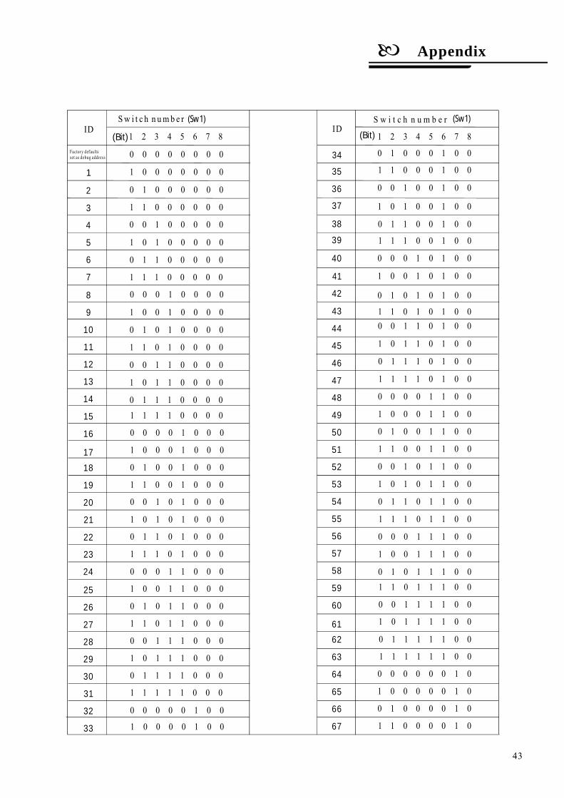
Sw i t c h n umb e rID
1
2
3
4
5
6
7
8
9
10
11
12
13
14
15
16
17
18
19
25
26
27
28
29
30
31
32
20
21
22
23
24
1 1 1 1 1 0 0 0
0 0 0 0 0 1 0 0
(Bit) 1 2 3 4 5 6 7 8
0 0 0 0 0 0 0 0
1 0 0 0 0 0 0 0
0 1 0 0 0 0 0 0
1 1 0 0 0 0 0 0
0 0 1 0 0 0 0 0
1 0 1 0 0 0 0 0
0 1 1 0 0 0 0 0
1 1 1 0 0 0 0 0
0 0 0 1 0 0 0 0
1 0 0 1 0 0 0 0
0 1 0 1 0 0 0 0
1 1 0 1 0 0 0 0
0 0 1 1 0 0 0 0
1 0 1 1 0 0 0 0
0 1 1 1 0 0 0 01 1 1 1 0 0 0 0
0 0 0 0 1 0 0 0
1 0 0 0 1 0 0 0
0 1 0 0 1 0 0 0
1 1 0 0 1 0 0 0
0 0 1 0 1 0 0 0
1 0 1 0 1 0 0 0
0 1 1 0 1 0 0 0
1 1 1 0 1 0 0 0
0 0 0 1 1 0 0 0
1 0 0 1 1 0 0 0
0 1 0 1 1 0 0 0
1 1 0 1 1 0 0 0
0 0 1 1 1 0 0 0
1 0 1 1 1 0 0 0
0 1 1 1 1 0 0 0
S w i t c h n u m b e rID
1 2 3 4 5 6 7 8
0 0 1 1 0 1 0 0
1 0 1 1 0 1 0 0
0 1 1 1 0 1 0 0
1 1 1 1 0 1 0 0
0 0 0 0 1 1 0 0
1 0 0 0 1 1 0 0
0 1 0 0 1 1 0 0
1 1 0 0 1 1 0 0
0 0 1 0 1 1 0 0
1 0 1 0 1 1 0 0
0 1 1 0 1 1 0 0
1 1 1 0 1 1 0 0
0 0 0 1 1 1 0 0
1 0 0 1 1 1 0 0
0 1 0 1 1 1 0 01 1 0 1 1 1 0 0
0 0 1 1 1 1 0 0
1 0 1 1 1 1 0 0
0 1 1 1 1 1 0 0
1 1 1 1 1 1 0 0
0 0 0 0 0 0 1 0
1 0 0 0 0 0 1 0
0 1 0 0 0 0 1 0
1 1 0 0 0 0 1 0
44
45
46
47
48
49
50
51
52
53
54
55
56
57
58
59
60
61
62
63
64
65
66
67
(Bit)
(Sw1)(Sw1)
33
34
1 0 0 0 0 1 0 0
0 1 0 0 0 1 0 0
1 1 0 0 0 1 0 0
0 0 1 0 0 1 0 0
1 0 1 0 0 1 0 0
0 1 1 0 0 1 0 0
1 1 1 0 0 1 0 0
0 0 0 1 0 1 0 0
1 0 0 1 0 1 0 0
0 1 0 1 0 1 0 0
1 1 0 1 0 1 0 0
35
36
37
38
39
40
41
42
43
Factory defaultsset as debug address
43
Appendix
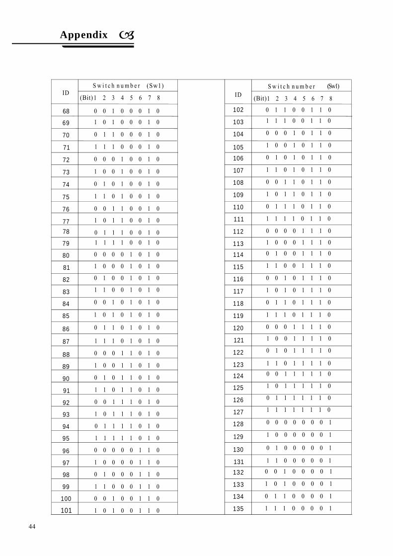
1 1 1 1 0 0 1 0
0 0 0 0 1 0 1 0
1 0 0 0 1 0 1 0
0 1 0 0 1 0 1 0
1 1 0 0 1 0 1 0
0 0 1 0 1 0 1 0
1 0 1 0 1 0 1 0
0 1 1 0 1 0 1 0
1 1 1 0 1 0 1 0
1 1 1 0 1 1 1 0
0 0 0 1 1 1 1 0
1 0 0 1 1 1 1 0
0 1 0 1 1 1 1 0
1 1 0 1 1 1 1 00 0 1 1 1 1 1 0
1 0 1 1 1 1 1 0
0 1 1 1 1 1 1 0
1 1 1 1 1 1 1 0
0 0 0 0 0 0 0 1
1 0 0 0 0 0 0 1
0 1 0 0 0 0 0 1
1 1 0 0 0 0 0 1
79
80
81
82
83
84
85
86
87
119
120
121
122
123
124
125
126
127
128
129
130
131
1 0 1 0 0 1 1 0
0 1 1 0 0 1 1 0
1 1 1 0 0 1 1 0
0 0 0 1 0 1 1 0
1 0 0 1 0 1 1 0
0 1 0 1 0 1 1 0
1 1 0 1 0 1 1 0
0 0 1 1 0 1 1 0
1 0 1 1 0 1 1 0
0 1 1 1 0 1 1 0
1 1 1 1 0 1 1 0
0 0 0 0 1 1 1 0
1 0 0 0 1 1 1 0
0 1 0 0 1 1 1 0
1 1 0 0 1 1 1 0
0 0 1 0 1 1 1 0
1 0 1 0 1 1 1 0
0 1 1 0 1 1 1 0
101
102
103
104
105
106
107
113
114
115
116
117
118
108
109
110
111
112
75
76
72
73
74
77
78
S w i t c h n u m b e rID
(Bit) 1 2 3 4 5 6 7 8
S w i t c h n um b e rID 1 2 3 4 5 6 7 8(Bit)
(Sw1)(Sw1)
1 1 0 1 0 0 1 0
0 0 1 1 0 0 1 0
0 0 1 0 0 0 1 0
1 0 1 0 0 0 1 0
0 1 1 0 0 0 1 0
1 1 1 0 0 0 1 0
0 0 0 1 0 0 1 0
1 0 0 1 0 0 1 0
0 1 0 1 0 0 1 0
1 0 1 1 0 0 1 0
0 1 1 1 0 0 1 0
69
70
71
68
0 0 0 1 1 0 1 0
1 0 0 1 1 0 1 0
0 1 0 1 1 0 1 0
1 1 0 1 1 0 1 0
0 0 1 1 1 0 1 0
1 0 1 1 1 0 1 0
0 1 1 1 1 0 1 0
1 1 1 1 1 0 1 0
0 0 0 0 0 1 1 0
1 0 0 0 0 1 1 0
0 1 0 0 0 1 1 0
1 1 0 0 0 1 1 0
0 0 1 0 0 1 1 0
89
90
91
92
93
94
95
96
97
98
99
100
88
0 0 1 0 0 0 0 1
1 0 1 0 0 0 0 1
0 1 1 0 0 0 0 1
1 1 1 0 0 0 0 1
132
133
134
135
44
Appendix
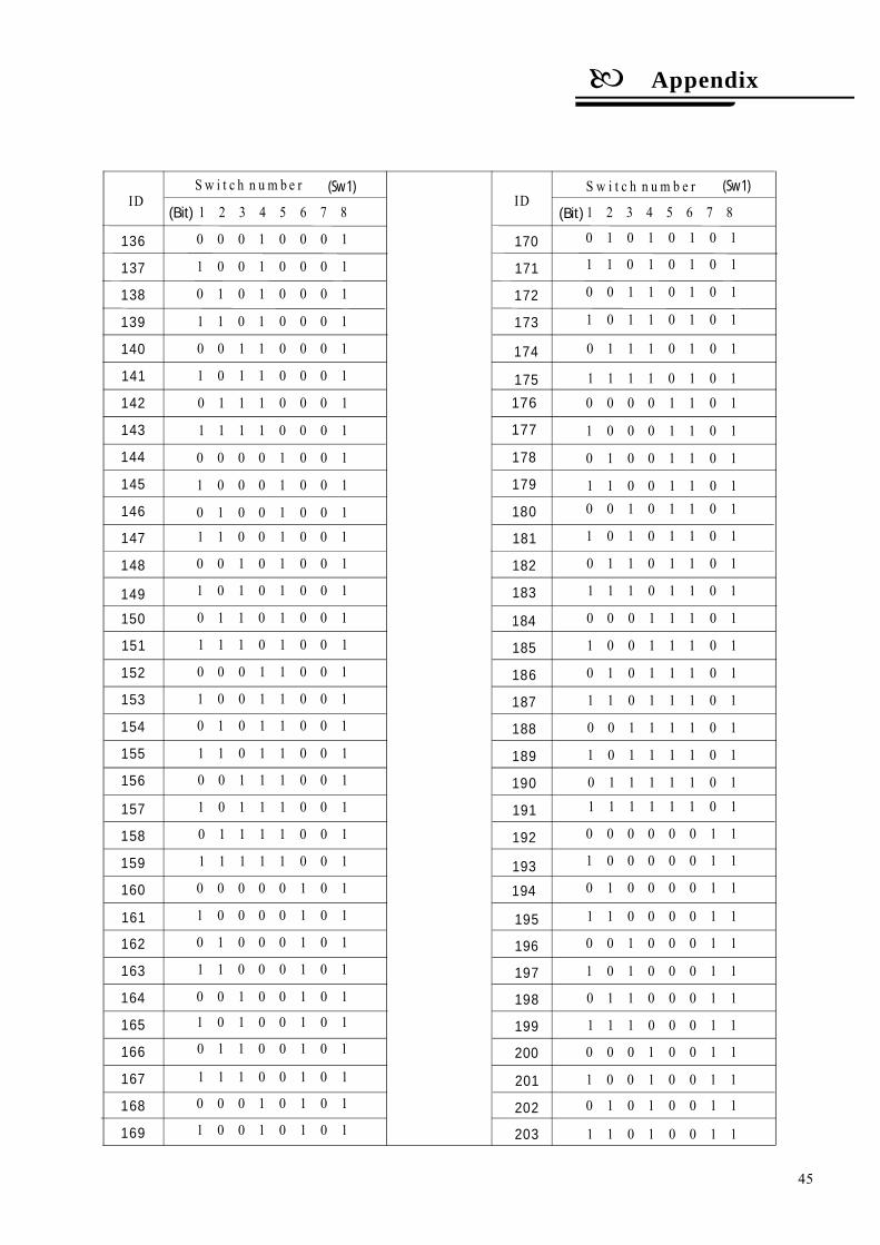
S w i t c h n u m b e rID
(Bit) 1 2 3 4 5 6 7 8
S w i t c h n u m b e rID
1 2 3 4 5 6 7 8(Bit)
(Sw1)(Sw1)
0 0 0 1 0 0 0 1
1 0 0 1 0 0 0 1
0 1 0 1 0 0 0 1
1 1 0 1 0 0 0 1
0 0 1 1 0 0 0 1
1 0 1 1 0 0 0 1
0 1 1 1 0 0 0 1
1 1 1 1 0 0 0 1
0 0 0 0 1 0 0 1
1 0 0 0 1 0 0 1
0 1 0 0 1 0 0 1
1 1 0 0 1 0 0 1
0 0 1 0 1 0 0 1
1 0 1 0 1 0 0 1
0 1 1 0 1 0 0 1
1 1 1 0 1 0 0 1
0 0 0 1 1 0 0 1
1 0 0 1 1 0 0 1
0 1 0 1 1 0 0 1
1 1 0 1 1 0 0 1
0 0 1 1 1 0 0 1
1 0 1 1 1 0 0 1
0 1 1 1 1 0 0 1
1 1 1 1 1 0 0 1
0 0 0 0 0 1 0 1
1 0 0 0 0 1 0 1
0 1 0 0 0 1 0 1
1 1 0 0 0 1 0 1
0 0 1 0 0 1 0 1
1 0 1 0 0 1 0 1
0 1 1 0 0 1 0 1
1 1 1 0 0 1 0 1
0 0 0 1 0 1 0 1
1 0 0 1 0 1 0 1
0 1 0 1 0 1 0 1
1 1 0 1 0 1 0 1
0 0 1 1 0 1 0 1
1 0 1 1 0 1 0 1
0 1 1 1 0 1 0 1
1 1 1 1 0 1 0 1
0 0 0 0 1 1 0 1
1 0 0 0 1 1 0 1
0 1 0 0 1 1 0 1
1 1 0 0 1 1 0 10 0 1 0 1 1 0 1
1 0 1 0 1 1 0 1
0 1 1 0 1 1 0 1
1 1 1 0 1 1 0 1
0 0 0 1 1 1 0 1
1 0 0 1 1 1 0 1
0 1 0 1 1 1 0 1
1 1 0 1 1 1 0 1
0 0 1 1 1 1 0 1
1 0 1 1 1 1 0 1
0 1 1 1 1 1 0 11 1 1 1 1 1 0 1
0 0 0 0 0 0 1 1
1 0 0 0 0 0 1 1
0 1 0 0 0 0 1 1
1 1 0 0 0 0 1 1
0 0 1 0 0 0 1 1
1 0 1 0 0 0 1 1
0 1 1 0 0 0 1 1
1 1 1 0 0 0 1 1
0 0 0 1 0 0 1 1
1 0 0 1 0 0 1 1
0 1 0 1 0 0 1 1
1 1 0 1 0 0 1 1
136
137
138
139
140
141
142
143
144
145
146
147
148
149
150
151
157
158
159
160
161
162
163
164
165
166
167
168
169
170
171
172
173
174
152
153
154
155
156
175
177
178
179
180
181
182
183
184
185
186
187
188
189
190
191
192
193
194
195
201
202
203
196
197
198
199
200
176
45
Appendix

Switch numberID
(Bit)1 2 3 4 5 6 7 8
Sw i t c h numb e rID
1 2 3 4 5 6 7 8(Bit)
(Sw1)( Sw1)
0 0 1 1 0 0 1 1
1 0 1 1 0 0 1 1
0 1 1 1 0 0 1 1
1 1 1 1 0 0 1 1
0 0 0 0 1 0 1 1
1 0 0 0 1 0 1 1
0 1 0 0 1 0 1 1
1 1 0 0 1 0 1 1
0 0 1 0 1 0 1 1
1 0 1 0 1 0 1 1
0 1 1 0 1 0 1 1
1 1 1 0 1 0 1 1
0 0 0 1 1 0 1 1
1 0 0 1 1 0 1 1
0 1 0 1 1 0 1 1
1 1 0 1 1 0 1 1
204
205
206
207
208
209
210
211
212
213
214
215
216
217
218
219
0 0 1 1 1 0 1 1
1 0 1 1 1 0 1 1
0 1 1 1 1 0 1 1
1 1 1 1 1 0 1 1
0 0 0 0 0 1 1 1
1 0 0 0 0 1 1 1
0 1 0 0 0 1 1 1
1 1 0 0 0 1 1 1
0 0 1 0 0 1 1 1
1 0 1 0 0 1 1 1
0 1 1 0 0 1 1 1
1 1 1 0 0 1 1 1
0 0 0 1 0 1 1 1
1 0 0 1 0 1 1 1
0 1 0 1 0 1 1 11 1 0 1 0 1 1 1
0 0 1 1 0 1 1 1
1 0 1 1 0 1 1 1
0 1 1 1 0 1 1 1
1 1 1 1 0 1 1 1
0 0 0 0 1 1 1 1
1 0 0 0 1 1 1 1
0 1 0 0 1 1 1 1
1 1 0 0 1 1 1 1
0 0 1 0 1 1 1 1
1 0 1 0 1 1 1 1
0 1 1 0 1 1 1 1
1 1 1 0 1 1 1 1
0 0 0 1 1 1 1 1
1 0 0 1 1 1 1 1
0 1 0 1 1 1 1 1
1 1 0 1 1 1 1 1
0 0 1 1 1 1 1 1
1 0 1 1 1 1 1 1
0 1 1 1 1 1 1 1
1 1 1 1 1 1 1 1
220
221
222
223
224
225
226
227
228
229
230
231
232
233
234
235
236
237
238
239
245
246
247
248
249
250
251
252
253
254
240
241
242
243
244
Notice: Debug address: (Only factory
protocol and Pelco can be set): if the camera
address is set as 0, user can select any
protocols to control the PTZ.
255
Appendix
46
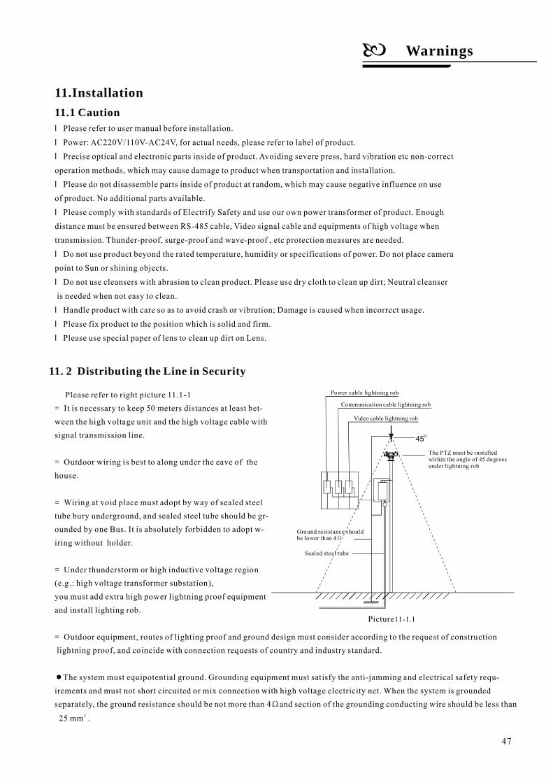
45O
Picture11-1.1
=
=
=
=
=
●
Please refer to right picture 11.1-1It is necessary to keep 50 meters distances at least bet-
ween the high voltage unit and the high voltage cable withsignal transmission line.
Outdoor wiring is best to along under the eave of thehouse.
Wiring at void place must adopt by way of sealed steeltube bury underground, and sealed steel tube should be gr-ounded by one Bus. It is absolutely forbidden to adopt w-iring without holder.
Under thunderstorm or high inductive voltage region(e.g.: high voltage transformer substation),you must add extra high power lightning proof equipmentand install lighting rob.
Outdoor equipment, routes of lighting proof and ground design must consider according to the request of constructionlightning proof, and coincide with connection requests of country and industry standard.
The system must equipotential ground. Grounding equipment must satisfy the anti-jamming and electrical safety requ-irements and must not short circuited or mix connection with high voltage electricity net. When the system is groundedseparately, the ground resistance should be not more than 4 and section of the grounding conducting wire should be less than
25 mm .
Ω2
The PTZ must be installedwithin the 45 degreesunder lightning rob
angle of
Ground resistance shouldbe lower than 4Ω
Sealed steel tube
Video cable lightning rob
Communication cable lightning rob
Power cable lightning rob
11.Installation11.1 Cautionl
l
l
l
l
l
l
l
l
l
Please refer to user manual before installation.
Power: , for actual needs, please refer to label of product.
Precise optical and electronic parts inside of product. Avoiding severe press, hard vibration etc non-correct
operation methods, which may cause damage to product when transportation and installation.
Please do not disassemble parts inside of product at random, which may cause negative influence on use
of product. No additional parts available.
Please comply with standards of Electrify Safety and use our own power transformer of product. Enough
distance must be ensured between RS-485 cable, Video signal cable and equipments of high voltage when
transmission. Thunder-proof, surge-proof and wave-proof , etc protection measures are needed.
Do not use product beyond the rated temperature, humidity or specifications of power. Do not place camera
point to Sun or shining objects.
Do not use cleansers with abrasion to clean product. Please use dry cloth to clean up dirt; Neutral cleanser
is needed when not easy to clean.
Handle product with care so as to avoid crash or vibration; Damage is caused when incorrect usage.
Please fix product to the position which is solid and firm.
Please use special paper of lens to clean up dirt on Lens.
220V/110V-AC24VAC
Warnings
11. 2 Distributing the Line in Security
47
This product uses TVS lightning Proof technology,can prevent from the damage of the equipment caused bykinds of pulse signal such as instant lightning strike ofpower below 4000V, the surge and so on.
At the same time, you must adopt the essential prote-ctive measure according to the actual situation regardingoutdoor installation under the guarantee electricity security.(Refer to chapter 1.3 Distributing the line in security)
11. 3
11. 4
Lightning Proof and Surge Proof
Water Proof
11.5 The preparation of installation
Outdoor PTZ has well waterproof moisture-proofdustproof performance, has achieved the IP66 internationalstandard.
All installation and maintenance work related thisproduct should complete by technical personnel whohave qualification of installation and maintenance.
Please refer to this handbook for detail.All electrical work must be observe local latest
electricity laws, regulation on fireproof as well asthe related laws and regulations:Checking everything is completed according to
packing list. Make sure the application place andthe way of installation for PTZ is coincide withthe request. If not, please contact your supplier.Please use this product according to the working
conditions request.Please handle with the pan/tilt module carefully,
do not extrude various structure parts; The downcover belongs to the senior optics part, do not touchwith hand; Please do not get through power exceptfor the electrifying inspection in process of installation.
Make sure you have enough space to hold this productand it's parts of installation in the site.Make sure the bearing capacity of ceiling, wall,
bracket that installs the PTZ support the gross weightof the PTZ and the structural parts of installation.It is necessary to have the safe coefficient of 4 timesor above.
、 、
The indoor PTZ doesn't allowed to install in out-door environment which is full of moisture and possibly en-ter water. You should prevent the product and the internalcomponents from damage that caused by the long time water-drop or spatter.
The request of the quality of installationperson and maintainer:
Basic requirements
Check the structure intensity for installationspace and installation site.
●
●
●
●
●
●
●
●
Ø
Ø
Ø
Warnings
Stuff PreparationPlease select the type of cables based on transmitting distance:Minimum video coaxial cable requirements:
1)75 impedance2)All copper conductor wire3)95% copper net structure
●
Ω
Ø
RG59/U 750ft 229m( )RG59/U
RG6/U
RG11/U
1,000ft 305m( )
1,500ft 457m( )
5C-2V
7C-2V
Domestic Gauge International Gauge Maximum Distance(ft/m)
●
●
RS485 Communication cables (Refer to manual appendix)24VAC Power supply cable (Refer to manual appendix)
Please preserve the mode original package materialproperly after opening the PTZ packing, in order tomail the PTZ that is wrapped with original packagematerial to the agent or return it to the factory to repairif problem occur.It is likely to bring on the damage that caused by the
transport accident on the way if the mode uses thenon-original package material, and extra cost mayarise accordingly.
Mounting way of pan/tilt: wall mount, top-downmount, stand-up mount.
Wall mountThe mounting place must bear four times weight of
PTZ/ mounting bracket and mounting base.The wall place you choose for mounting site must be
stability and nothing to take off, and make sure thebracket is mounted in the wall not the non-surfaceobject.
●
●
●
Stand-up mount
Top-down mount
The mounting place must meet the requirement ofchapter 1.3 distributing the line in security.The pole bracket must be stability and no wobble.
The mounting position must undertake the weight ofpan-tilt.Such a mounting way is only suitable for top-down type.Otherwise, it would be water-leaking.
Ø Keep All the Original Package Materials
Ø Brief introduction of mounting way
48
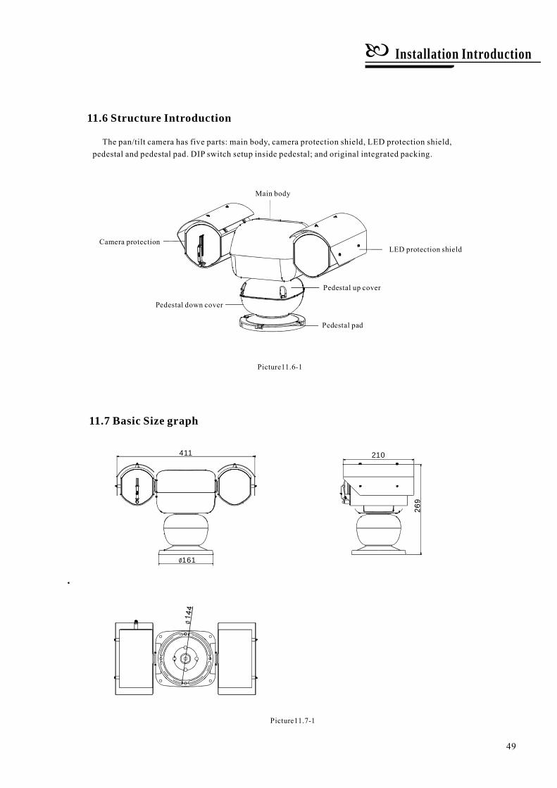
Picture11.6-1
The pan/tilt camera has five parts: main body, camera protection shield, LED protection shield,pedestal and pedestal pad. DIP switch setup inside pedestal; and original integrated packing.
11.7 Basic Size graph
Pedestal pad
Pedestal down cover
Camera protectionLED protection shield
Pedestal up cover
Main body
11.6 Structure Introduction
Picture11.7-1
Installation Introduction
411 210
161
49
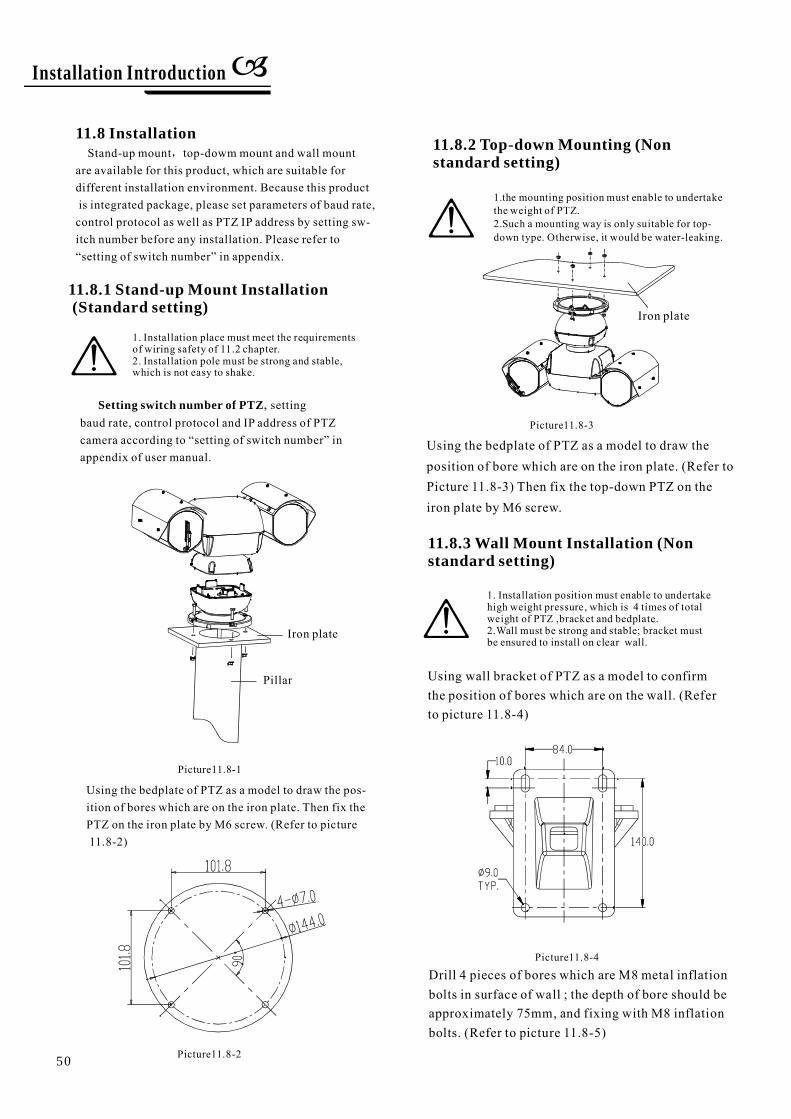
Pillar
Iron plate
Using the bedplate of PTZ as a model to draw the pos-ition of bores which are on the iron plate. Then fix thePTZ on the iron plate by M6 screw. (Refer to picture11.8-2)
11.8 InstallationStand-up mount top-dowm mount and wall mount
are available for this product, which are suitable fordifferent installation environment. Because this productis integrated package, please set parameters of baud rate,control protocol as well as PTZ IP address by setting sw-itch number before any installation. Please refer to
in appendix.
,
“setting of switch number”
11.8.1 Stand-up Mount Installation(Standard setting)
1. Installation place must meet the requirementsof wiring safety of 11.2 chapter.2. Installation pole must be strong and stable,which is not easy to shake.
Setting switch number of PTZ, settingbaud rate, control protocol and IP address of PTZcamera according to inappendix of user manual.
“setting of switch number”
Picture11.8-2
Picture11.8-1
11.8.3 Wall Mount Installation (Nonstandard setting)
1. Installation position must enable to undertakehigh weight pressure, which is 4 times of totalweight of PTZ ,bracket and bedplate.2.Wall must be strong and stable; bracket mustbe ensured to install on clear wall.
Using wall bracket of PTZ as a model to confirmthe position of bores which are on the wall. (Referto picture 11.8-4)
11.8.2 Top-down Mounting (Nonstandard setting)
Iron plate
Picture11.8-3
Using the bedplate of PTZ as a model to draw theposition of bore which are on the iron plate. (Refer toPicture 11.8-3) Then fix the top-down PTZ on theiron plate by M6 screw.
1.the mounting position must enable to undertakethe weight of PTZ.2.Such a mounting way is only suitable for top-down type. Otherwise, it would be water-leaking.
Picture11.8-4
Installation Introduction
Drill 4 pieces of bores which are M8 metal inflationbolts in surface of wall ; the depth of bore should beapproximately 75mm, and fixing with M8 inflationbolts. (Refer to picture 11.8-5)
50
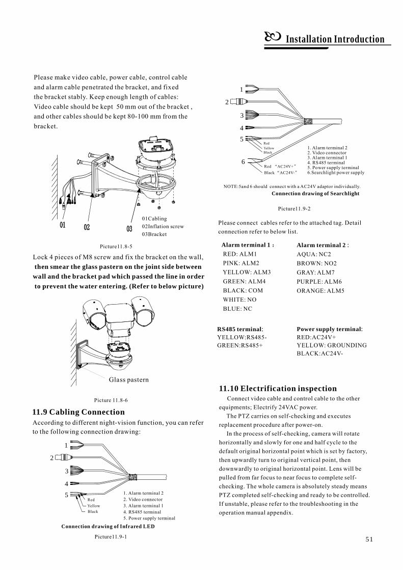
Please make video cable, power cable, control cableand alarm cable penetrated the bracket, and fixedthe bracket stably. Keep enough length of cables:Video cable should be kept 50 mm out of the bracket ,and other cables should be kept 80-100 mm from thebracket.
Lock 4 pieces of M8 screw and fix the bracket on the wall,then smear the glass pastern on the joint side between
wall and the bracket pad which passed the line in orderto prevent the water entering. (Refer to below picture)
Picture 11.8-6
Glass pastern
:
AQUA: NC2BROWN: NO2GRAY: ALM7PURPLE: ALM6ORANGE: ALM5
Alarm terminal 2Alarm terminal 1:RED: ALM1PINK: ALM2YELLOW: ALM3GREEN: ALM4BLACK: COMWHITE: NOBLUE: NC
RS485 terminal:YELLOW:RS485-GREEN:RS485+
Power supply terminal:RED:AC24V+YELLOW: GROUNDINGBLACK:AC24V-
Picture11.9-1
11.9 Cabling Connection
Please connect cables refer to the attached tag. Detailconnection refer to below list.
11.10 Electrification inspectionConnect video cable and control cable to the other
equipments; Electrify 24VAC power.The PTZ carries on self-checking and executes
replacement procedure after power-on.In the process of self-checking, camera will rotate
horizontally and slowly for one and half cycle to thedefault original horizontal point which is set by factory,then upwardly turn to original vertical point, thendownwardly to original horizontal point. Lens will bepulled from far focus to near focus to complete self-checking. The whole camera is absolutely steady meansPTZ completed self-checking and ready to be controlled.If unstable, please refer to the troubleshooting in theoperation manual appendix.
Picture11.8-5
01Cabling02Inflation screw03Bracket
1
2
3
4
5 1. Alarm terminal 22. Video connector3. Alarm terminal 14. RS485 terminal5. Power supply terminal
YellowBlack
Red
Connection drawing of Infrared LED
Picture11.9-2
According to different night-vision function, you can referto the following connection drawing:
1. Alarm terminal 22. Video connector3. Alarm terminal 14. RS485 terminal5. Power supply terminal6.Searchlight power supply
Red AC24V+“ ”
Black AC24V-“ ”
RedYellowBlack
5
6
1
2
3
4
NOTE:5and 6 should connect with a AC24V adaptor individually.Connection drawing of Searchlight
51
Installation Introduction
12.Maintenance service terms
Maintenance
52
1. Range of warranty
●
●
●
●
●
●
●
●
●
●
●
●
For the damage and loss which was caused by the user's specifically application, factory won't bear any risk
and responsibility. The factory compensation made by breach of faith, negligence or tortious won't exceed the
amount of the products. The factory won't bear any responsibility for the special, unexpected and continue
damage caused by any other reasons.
Our company has the final right of explanation for the above terms.
If the products are within the warranty time, the buyer should fill in the warranty card and send back together
with the products.
If the product needs repaired , you can return it to the manufacturer through the supplier or directly. If you
choose the later , please contact us in order to speed up the process. And our company only undertake the
one-way freight from manufacturer to customer after maintenance.
2. Warranty terms
3. Shipping
The product will be maintained free for one year.
The product will be obtained the free maintenance service if the same malfunction appears again within three
months.
Malfunction of products caused by force majeure (such as war, earthquake, lightning strike and so on ), abuse,
non-standard operation, change of construction, non-normal wear or accident are non-free of warranty.
Please prevent from the damage which is caused by heavy pressure , the fierce vibration and soaks in the
process of transportation and storage, which does not belong to the free maintenance scope.
Please adopt the way of fission package or original package to transport because the product damage dose
not belong to the free maintenance scope if you use the whole packing way , not the original packing way.
The maintenance services will not be free when the pan/tilt module is disassembled or serviced by the user
voluntarily.
Our company implements the lifetime payable service if the product in malfunction has surpassed the
warranty period.
To the products with defect :if it's in the period of warranty, please fill in the form of warranty information
correctly, describe the trouble in details, and provide original sales. invoice or its copy.

Intelligence Heavy-duty PTZ CameraUser ManualVersion V2.11.140430
AVUE
Typewritten Text
AVUE 1180 MIRALOMA WAY SUITE C SUNNYVALE, CA 94085 WWW.AVUEINC.COM 408.481.9355; [email protected]
AVUE
Typewritten Text
AVUE
Typewritten Text
Related Documents