DoAFT 3/26/07 INSTRUCTION MANUAL vacuum technologies TASK Turbo Pumping System Manual No. 699933001 Revision C March 2007

Welcome message from author
This document is posted to help you gain knowledge. Please leave a comment to let me know what you think about it! Share it to your friends and learn new things together.
Transcript
oA
FT
3/2
6/0
7
INSTRUCTION MANUAL
vacuum technologies
TASK Turbo Pumping System
D
Manual No. 699933001Revision CMarch 2007
Donald Grefe'
Agilent
DR
AF
T 3
/26
/07
TASK Turbo Pumping System
ConFlat Flange is a registered trademark of Varian, Inc.
Copyright 2007Varian, Inc.
TASK Turbo Pumping System
DR
AF
T 3
/26
/07
WarrantyProducts manufactured by Seller are warranted against defects in materials and workmanship for twelve (12) months from date of shipment thereof to Customer, and Seller’s liability under valid warranty claims is limited, at the option of Seller, to repair, to replace, or refund of an equitable portion of the purchase price of the Product. Items expendable in normal use are not covered by this warranty. All warranty replacement or repair of parts shall be limited to equipment malfunctions which, in the sole opinion of Seller, are due or traceable to defects in original materials or workmanship. All obligations of Seller under this warranty shall cease in the event of abuse, accident, alteration, misuse, or neglect of the equipment. In-warranty repaired or replaced parts are warranted only for the remaining unexpired portion of the original warranty period applicable to the repaired or replaced parts. After expiration of the applicable warranty period, Customer shall be charged at the then current prices for parts, labor, and transportation.
Reasonable care must be used to avoid hazards. Seller expressly disclaims responsibility for loss or damage caused by use of its Products other than in accordance with proper operating procedures.
Except as stated herein, Seller makes no warranty, express or implied (either in fact or by operation of law), statutory or otherwise; and, except as stated herein, Seller shall have no liability under any war-ranty, express or implied (either in fact or by operation of law), statutory or otherwise. Statements made by any person, including representatives of Seller, which are inconsistent or in conflict with the terms of this warranty shall not be binding upon Seller unless reduced to writing and approved by an officer of Seller.
Warranty Replacement and AdjustmentAll claims under warranty must be made promptly after occurrence of circumstances giving rise thereto, and must be received within the applicable warranty period by Seller or its authorized representative. Such claims should include the Product serial number, the date of shipment, and a full description of the circumstances giving rise to the claim. Before any Products are returned for repair and/or adjust-ment, written authorization from Seller or its authorized representative for the return and instructions as to how and where these Products should be returned must be obtained. Any Product returned to Seller for examination shall be prepaid via the means of transportation indicated as acceptable by Seller. Seller reserves the right to reject any warranty claim not promptly reported and any warranty claim on any item that has been altered or has been returned by non-acceptable means of transportation. When any Product is returned for examination and inspection, or for any other reason, Customer shall be responsible for all damage resulting from improper packing or handling, and for loss in transit, notwith-standing any defect or non-conformity in the Product. In all cases, Seller has the sole responsibility for determining the cause and nature of failure, and Seller’s determination with regard thereto shall be final.
If it is found that Seller’s Product has been returned without cause and is still serviceable, Customer will be notified and the Product returned at Customer’s expense; in addition, a charge for testing and exam-ination may be made on Products so returned.
3/1/00
iii

TASK Turbo Pumping System D
RA
FT
3/2
6/0
7
This page intentionally left blank.
TASK Turbo Pumping System
DR
AF
T 3
/26
/07
Table of Contents
Preface ............................................................................................................................................ xiiWarnings, Cautions and Notes .................................................................................................... xiiTASK System Hazards ................................................................................................................. xiiEMC Warnings ........................................................................................................................... xiiiAbout this Manual ......................................................................................................................xivMaintenance ................................................................................................................................xv
Introduction and Installation ........................................................................................................ 1-1Storage........................................................................................................................................ 1-1Controller Description ................................................................................................................ 1-2
Controller Interface ............................................................................................................... 1-2Installation .................................................................................................................................. 1-4
General................................................................................................................................. 1-4Installation Procedure ........................................................................................................... 1-5
Operation ....................................................................................................................................... 2-1Startup ........................................................................................................................................ 2-1TASK System Shutdown .............................................................................................................. 2-2Power Failure.............................................................................................................................. 2-2Troubleshooting.......................................................................................................................... 2-2
TASK System Start-Up Troubleshooting ................................................................................. 2-2One-Button Start Configuration Procedure ............................................................................ 2-3SH-110 Troubleshooting ....................................................................................................... 2-6
Appendix A. Specifications and System Configurations ......................................................... A-1Request for Return Health and Safety CertificationSales and Service Offices
v

TASK Turbo Pumping System D
RA
FT
3/2
6/0
7
This page intentionally left blank.
TASK Turbo Pumping System
DR
AF
T 3
/26
/07
List of Figures
Figure Caption Page1-1 V-81-AG Font Panel............................................................................................................. 1-21-2 TASK System – Front View ................................................................................................... 1-51-3 TASK System – Rear View .................................................................................................... 1-51-4 ISO Flange Connection ........................................................................................................ 1-61-5 KF Flange Connection.......................................................................................................... 1-71-6 ConFlat Flange Connection.................................................................................................. 1-7
vii

TASK Turbo Pumping System D
RA
FT
3/2
6/0
7
This page intentionally left blank.
TASK Turbo Pumping System
DR
AF
T 3
/26
/07
List of Tables
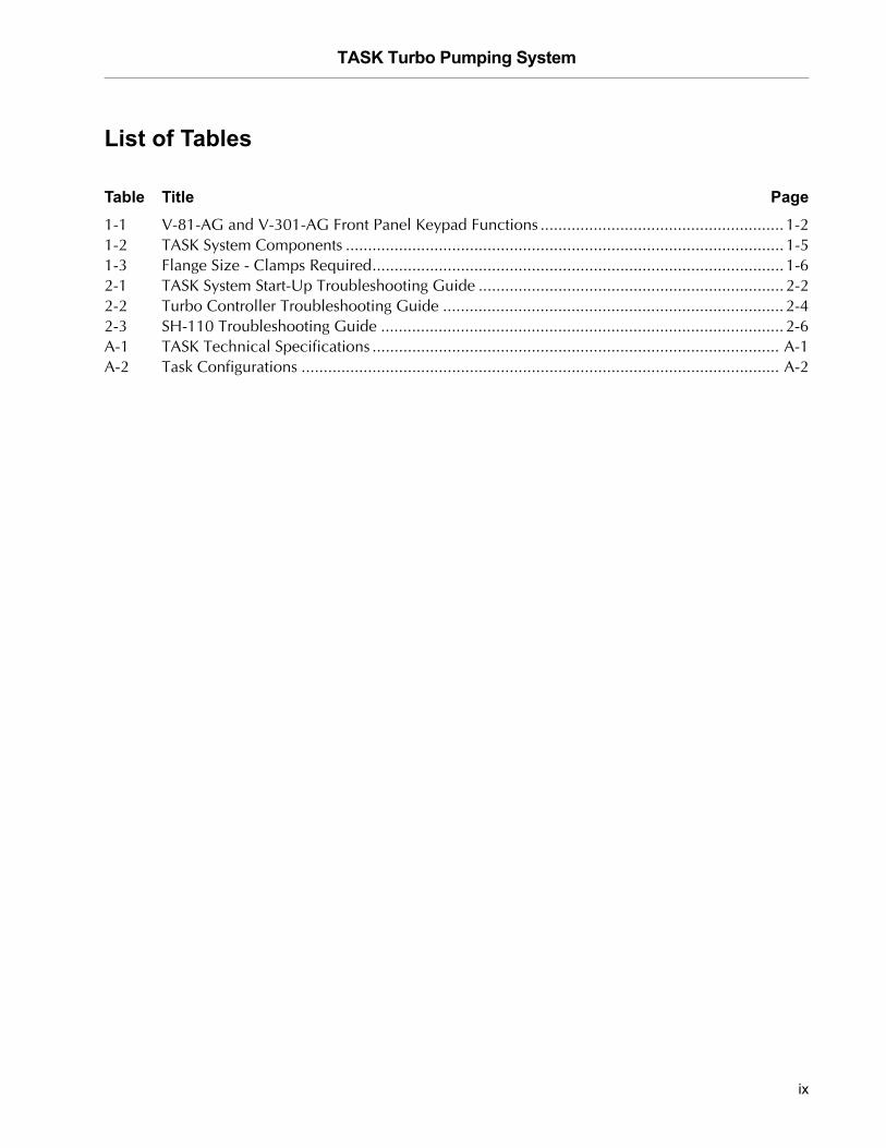
Table Title Page1-1 V-81-AG and V-301-AG Front Panel Keypad Functions ....................................................... 1-21-2 TASK System Components ................................................................................................... 1-51-3 Flange Size - Clamps Required............................................................................................. 1-62-1 TASK System Start-Up Troubleshooting Guide ..................................................................... 2-22-2 Turbo Controller Troubleshooting Guide ............................................................................. 2-42-3 SH-110 Troubleshooting Guide ........................................................................................... 2-6A-1 TASK Technical Specifications ............................................................................................ A-1A-2 Task Configurations ............................................................................................................ A-2
ix

TASK Turbo Pumping System D
RA
FT
3/2
6/0
7
This page intentionally left blank.
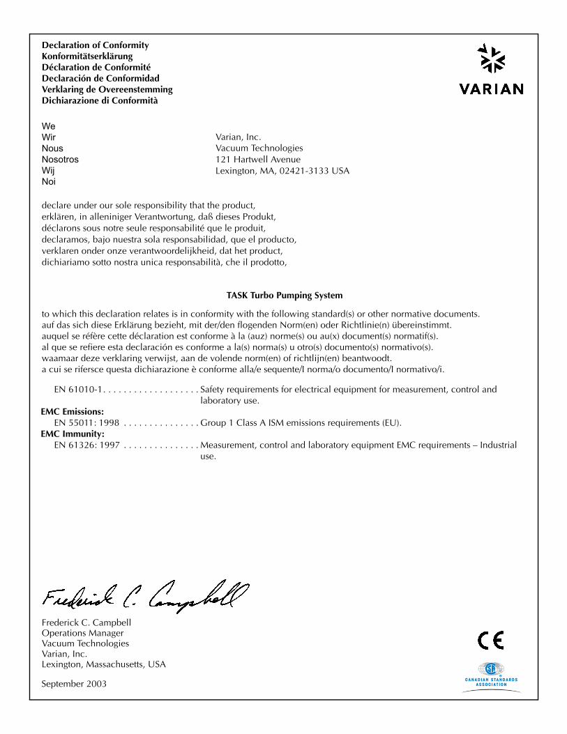
Varian, Inc.
declare under our sole responsibility that the product,erklären, in alleniniger Verantwortung, daß dieses Produkt,déclarons sous notre seule responsabilité que le produit,declaramos, bajo nuestra sola responsabilidad, que el producto,verklaren onder onze verantwoordelijkheid, dat het product,dichiariamo sotto nostra unica responsabilità, che il prodotto,
Declaration of ConformityKonformitätserklärungDéclaration de ConformitéDeclaración de ConformidadVerklaring de OvereenstemmingDichiarazione di Conformità
WeWirNousNosotrosWijNoi
Lexington, MA, 02421-3133 USA 121 Hartwell AvenueVacuum Technologies
TASK Turbo Pumping System
to which this declaration relates is in conformity with the following standard(s) or other normative documents.auf das sich diese Erklärung bezieht, mit der/den flogenden Norm(en) oder Richtlinie(n) übereinstimmt.auquel se réfère cette déclaration est conforme à la (auz) norme(s) ou au(x) document(s) normatif(s).al que se refiere esta declaración es conforme a la(s) norma(s) u otro(s) documento(s) normativo(s).waamaar deze verklaring verwijst, aan de volende norm(en) of richtlijn(en) beantwoodt.a cui se rifersce questa dichiarazione è conforme alla/e sequente/I norma/o documento/I normativo/i.
EN 61010-1. . . . . . . . . . . . . . . . . . . Safety requirements for electrical equipment for measurement, control and laboratory use.
EMC Emissions:EN 55011: 1998 . . . . . . . . . . . . . . . Group 1 Class A ISM emissions requirements (EU).
EMC Immunity:EN 61326: 1997 . . . . . . . . . . . . . . . Measurement, control and laboratory equipment EMC requirements – Industrial
use.
Frederick C. CampbellOperations ManagerVacuum Technologies
Lexington, Massachusetts, USAVarian, Inc.
September 2003
TASK Turbo Pumping System D
RA
FT
3/2
6/0
7
Preface
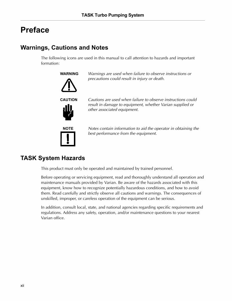
Warnings, Cautions and NotesThe following icons are used in this manual to call attention to hazards and important formation:
WARNING Warnings are used when failure to observe instructions or precautions could result in injury or death.
CAUTION Cautions are used when failure to observe instructions could result in damage to equipment, whether Varian supplied or other associated equipment.
NOTE Notes contain information to aid the operator in obtaining the best performance from the equipment.
TASK System HazardsThis product must only be operated and maintained by trained personnel.
Before operating or servicing equipment, read and thoroughly understand all operation and maintenance manuals provided by Varian. Be aware of the hazards associated with this equipment, know how to recognize potentially hazardous conditions, and how to avoid them. Read carefully and strictly observe all cautions and warnings. The consequences of unskilled, improper, or careless operation of the equipment can be serious.
In addition, consult local, state, and national agencies regarding specific requirements and regulations. Address any safety, operation, and/or maintenance questions to your nearest Varian office.
xii
TASK Turbo Pumping System
DR
AF
T 3
/26
/07
EMC Warnings
EN 55022 Class A Warning
This is a Class A product. In a domestic environment this product may cause radio interference in which case the user may be required to take adequate measures.
FCC
This device complies with Part 15 of the FCC rules. Operation is subject to the following two conditions: (1) This device may not cause harmful interference, and (2) this device must accept any interference received, including interference that may cause undesirable operation.
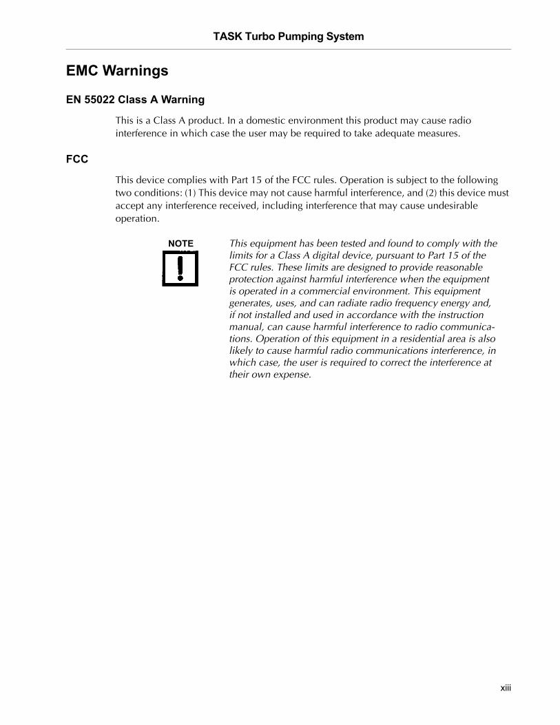
NOTE This equipment has been tested and found to comply with the limits for a Class A digital device, pursuant to Part 15 of the FCC rules. These limits are designed to provide reasonable protection against harmful interference when the equipment is operated in a commercial environment. This equipment generates, uses, and can radiate radio frequency energy and, if not installed and used in accordance with the instruction manual, can cause harmful interference to radio communica-tions. Operation of this equipment in a residential area is also likely to cause harmful radio communications interference, in which case, the user is required to correct the interference at their own expense.
xiii
TASK Turbo Pumping System D
RA
FT
3/2
6/0
7
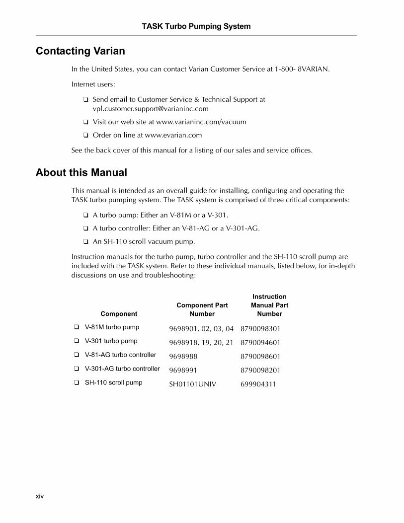
Contacting VarianIn the United States, you can contact Varian Customer Service at 1-800- 8VARIAN.
Internet users:
❑ Send email to Customer Service & Technical Support at [email protected]
❑ Visit our web site at www.varianinc.com/vacuum
❑ Order on line at www.evarian.com
See the back cover of this manual for a listing of our sales and service offices.
About this ManualThis manual is intended as an overall guide for installing, configuring and operating the TASK turbo pumping system. The TASK system is comprised of three critical components:
❑ A turbo pump: Either an V-81M or a V-301.
❑ A turbo controller: Either an V-81-AG or a V-301-AG.
❑ An SH-110 scroll vacuum pump.
Instruction manuals for the turbo pump, turbo controller and the SH-110 scroll pump are included with the TASK system. Refer to these individual manuals, listed below, for in-depth discussions on use and troubleshooting:
ComponentComponent Part
Number
Instruction Manual Part
Number
❑ V-81M turbo pump 9698901, 02, 03, 04 8790098301
❑ V-301 turbo pump 9698918, 19, 20, 21 8790094601
❑ V-81-AG turbo controller 9698988 8790098601
❑ V-301-AG turbo controller 9698991 8790098201
❑ SH-110 scroll pump SH01101UNIV 699904311
xiv
TASK Turbo Pumping System
DR
AF
T 3
/26
/07
MaintenancePersonnel responsible for pump operation and maintenance must be well-trained and aware of the accident prevention rules.
WARNING ❑ Death can result from contact with high voltages. Always take extreme care and observe the accident prevention regulations in force.
❑ When the machine is powered up, be careful of moving parts and high voltages.
❑ If you have to perform maintenance on the pump after a considerable time in operation, allow it to cool as the temperature of the outer surface may be in excess of 60 °C.
❑ Always disconnect the pump power supply before beginning maintenance work.
NOTE Before returning the pump to the factory for repair, the Health and Safety sheet in this manual must be completed and sent to the local sales office. A copy of the sheet must be inserted in the pump package before shipping.
Dispose of the pump in accordance with specific national standards.
xv

TASK Turbo Pumping System D
RA
FT
3/2
6/0
7
This page intentionally left blank.
TASK Turbo Pumping System
DR
AF
T 3
/26
/07
Introduction and Installation
TASK is an indoor, bench-top turbo pumping system that is comprised of an SH–110 Scroll backing pump and either a V- 81M or V-301 turbomolecular pump. TASK produces an oil-free high vacuum, while maintaining one button operation. The system is available with a variety of different inlet flanges (see Appendix A “Specifications and System Configurations”).
The SH-110 is a hermetic, dry scroll vacuum pump suitable for pumping air or inert gases. The pump is not intended to pump toxic, corrosive, explosive, or particulate-forming gases.
The turbopump controllers are microprocessor-based frequency converters with self-diagnostic and protection features to ensure the highest degree of reliability. They display all of the relevant operating parameters and pump status information.
TASK system features include:
❑ One button operation
❑ Available in 120 VAC (50/60 Hz) or 220 VAC (50/60 Hz)
❑ Oil free high vacuum performance
❑ CE and CSA approvals
❑ Lifting hand holds
❑ KF, ISO or ConFlat flanges
❑ Manual turbo vent valve
❑ NW16 / ¼” FNPT exhaust connection
❑ Compact console
❑ Air-cooled vented case
StorageWhen transporting and storing the TASK system, do not exceed the following environmental requirements:
Temperature -20 °C to +60 °C (-4 of to 140 °F)
Relative humidity 0 to 95% (non-condensing)
1-1
TASK Turbo Pumping System D
RA
FT
3/2
6/0
7
Controller DescriptionThe controller is available in two versions that operate with the voltage range listed below:
❑ V-81-AG: Model 969-8988 (100-240 Vac, 50-60 Hz)
❑ V-301-AG: Model 969-8911 (100-240 Vac, 50-60 Hz)
The Turbo V-81-AG and V-301-AG Rack controller is a micro-processor controlled frequency converter with a new, enhanced feature that allows for greater control and communication capabilities. This compact, 1/4 rack unit is designed for full worldwide compatibility for vent valve control, active gauge pressure reading and pump operation parameters control, as well as for self diagnostic and protection features.
Controller Interface
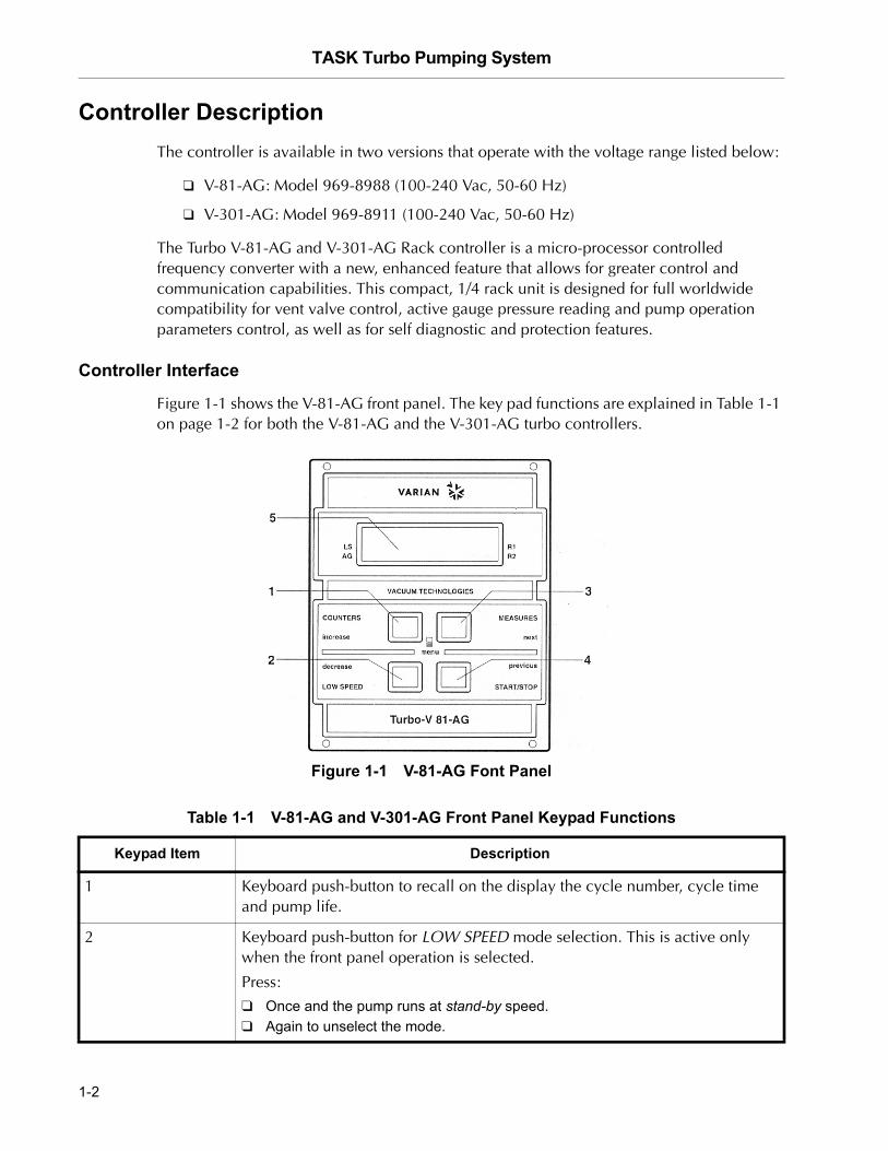
Figure 1-1 shows the V-81-AG front panel. The key pad functions are explained in Table 1-1 on page 1-2 for both the V-81-AG and the V-301-AG turbo controllers.
Figure 1-1 V-81-AG Font Panel
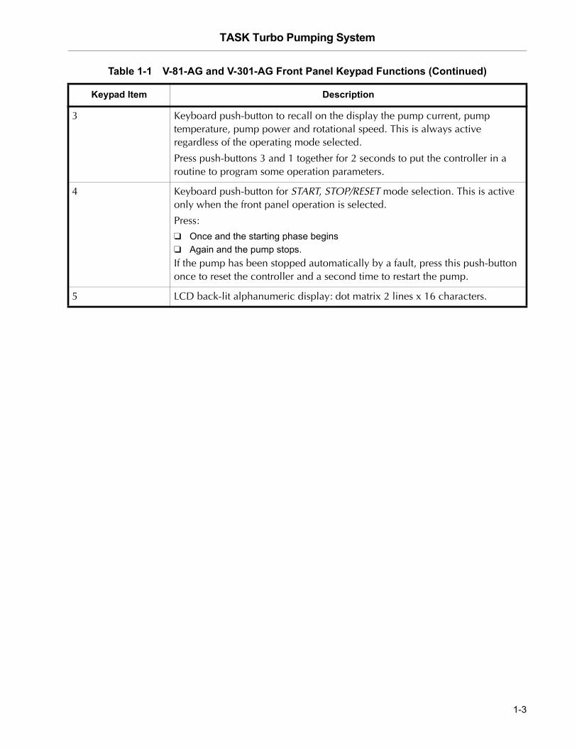
Table 1-1 V-81-AG and V-301-AG Front Panel Keypad Functions
Keypad Item Description
1 Keyboard push-button to recall on the display the cycle number, cycle time and pump life.
2 Keyboard push-button for LOW SPEED mode selection. This is active only when the front panel operation is selected.
Press:❑ Once and the pump runs at stand-by speed.❑ Again to unselect the mode.
1-2
TASK Turbo Pumping System
DR
AF
T 3
/26
/07
3 Keyboard push-button to recall on the display the pump current, pump temperature, pump power and rotational speed. This is always active regardless of the operating mode selected.
Press push-buttons 3 and 1 together for 2 seconds to put the controller in a routine to program some operation parameters.
4 Keyboard push-button for START, STOP/RESET mode selection. This is active only when the front panel operation is selected.
Press:
❑ Once and the starting phase begins❑ Again and the pump stops.If the pump has been stopped automatically by a fault, press this push-button once to reset the controller and a second time to restart the pump.
5 LCD back-lit alphanumeric display: dot matrix 2 lines x 16 characters.
Table 1-1 V-81-AG and V-301-AG Front Panel Keypad Functions (Continued)
Keypad Item Description
1-3
TASK Turbo Pumping System D
RA
FT
3/2
6/0
7
Installation
General
The TASK system is shipped with a plastic protective cover to prevent debris from entering the turbo pump. If the cover shows signs of damage, which may have occurred during transport, contact your local sales office. Always take care to prevent anything, including fingers, from touching the turbo blades. The use of an inlet screen is recommended (factory installed).
Obey the following:
❑ Use this equipment only on a sturdy, horizontal surface and indoors.
❑ Do not install or use the pump in an environment exposed to atmospheric agents (rain, snow, ice), dust, aggressive gases, or in explosive environments or those with a high fire risk.
❑ During operation, the following environmental conditions must be maintained:
❑ Temperature: +5 °C to +35 °C (41 to 95 °F)
❑ Relative humidity: 0 to 95% (non-condensing)
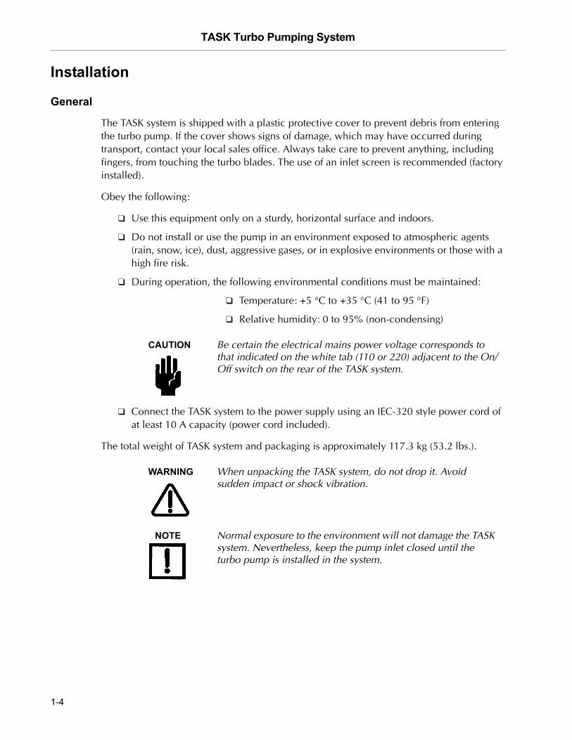
CAUTION Be certain the electrical mains power voltage corresponds to that indicated on the white tab (110 or 220) adjacent to the On/Off switch on the rear of the TASK system.
❑ Connect the TASK system to the power supply using an IEC-320 style power cord of at least 10 A capacity (power cord included).
The total weight of TASK system and packaging is approximately 117.3 kg (53.2 lbs.).
WARNING When unpacking the TASK system, do not drop it. Avoid sudden impact or shock vibration.
NOTE Normal exposure to the environment will not damage the TASK system. Nevertheless, keep the pump inlet closed until the turbo pump is installed in the system.
1-4
TASK Turbo Pumping System
DR
AF
T 3
/26
/07
Installation Procedure
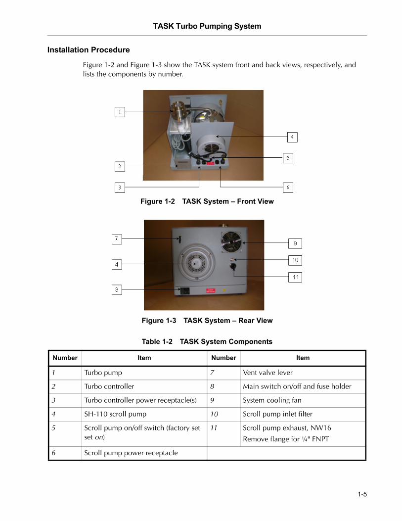
Figure 1-2 and Figure 1-3 show the TASK system front and back views, respectively, and lists the components by number.
Figure 1-2 TASK System – Front View
Figure 1-3 TASK System – Rear View
Table 1-2 TASK System Components
Number Item Number Item
1 Turbo pump 7 Vent valve lever
2 Turbo controller 8 Main switch on/off and fuse holder
3 Turbo controller power receptacle(s) 9 System cooling fan
4 SH-110 scroll pump 10 Scroll pump inlet filter
5 Scroll pump on/off switch (factory set set on)
11 Scroll pump exhaust, NW16
Remove flange for ¼" FNPT
6 Scroll pump power receptacle
1-5
TASK Turbo Pumping System D
RA
FT
3/2
6/0
7
There are three types of inlet flange connections for the TASK pumping system:
❑ “ISO Inlet Flange”
❑ “KF Inlet Flange” on page 1-7
❑ “ConFlat Inlet Flange” on page 1-7
ISO Inlet Flange
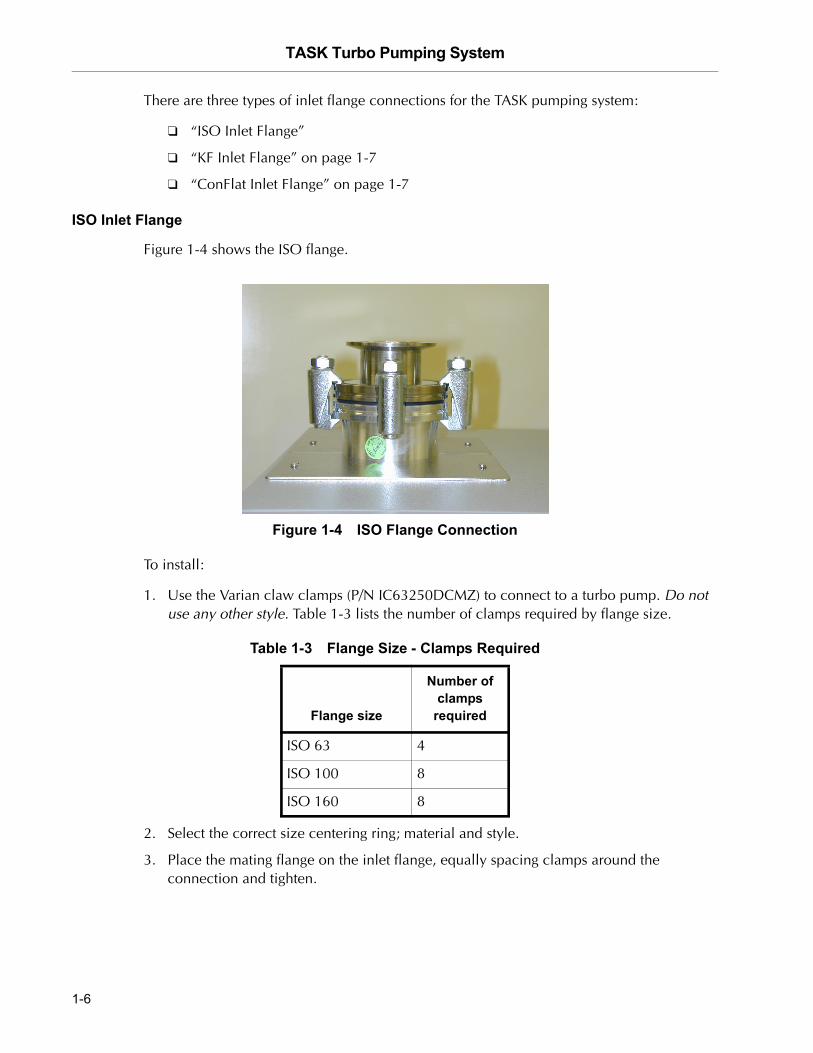
Figure 1-4 shows the ISO flange.
Figure 1-4 ISO Flange Connection
To install:
1. Use the Varian claw clamps (P/N IC63250DCMZ) to connect to a turbo pump. Do not use any other style. Table 1-3 lists the number of clamps required by flange size.
2. Select the correct size centering ring; material and style.
3. Place the mating flange on the inlet flange, equally spacing clamps around the connection and tighten.
Table 1-3 Flange Size - Clamps Required
Flange size
Number of clamps
required
ISO 63 4
ISO 100 8
ISO 160 8
1-6
TASK Turbo Pumping System
DR
AF
T 3
/26
/07
KF Inlet Flange
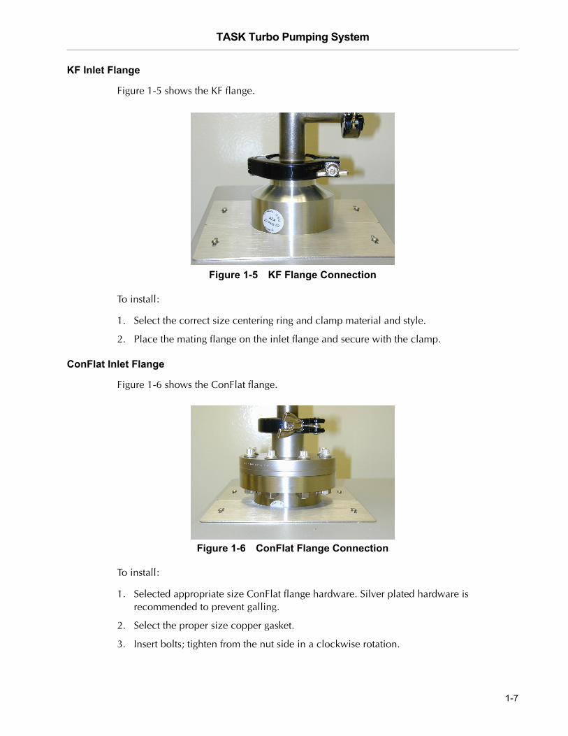
Figure 1-5 shows the KF flange.
Figure 1-5 KF Flange Connection
To install:
1. Select the correct size centering ring and clamp material and style.
2. Place the mating flange on the inlet flange and secure with the clamp.
ConFlat Inlet Flange
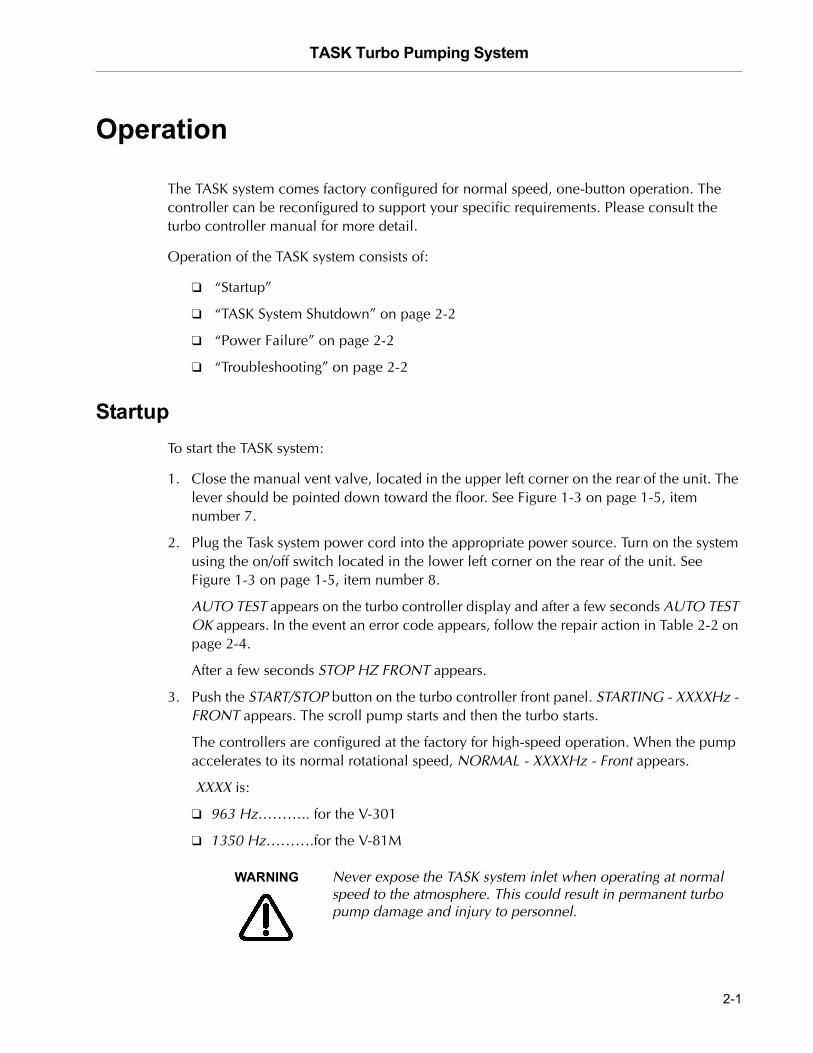
Figure 1-6 shows the ConFlat flange.
Figure 1-6 ConFlat Flange Connection
To install:
1. Selected appropriate size ConFlat flange hardware. Silver plated hardware is recommended to prevent galling.
2. Select the proper size copper gasket.
3. Insert bolts; tighten from the nut side in a clockwise rotation.
1-7

TASK Turbo Pumping System D
RA
FT
3/2
6/0
7
This page intentionally left blank.
TASK Turbo Pumping System
DR
AF
T 3
/26
/07
Operation
The TASK system comes factory configured for normal speed, one-button operation. The controller can be reconfigured to support your specific requirements. Please consult the turbo controller manual for more detail.
Operation of the TASK system consists of:
❑ “Startup”
❑ “TASK System Shutdown” on page 2-2
❑ “Power Failure” on page 2-2
❑ “Troubleshooting” on page 2-2
StartupTo start the TASK system:
1. Close the manual vent valve, located in the upper left corner on the rear of the unit. The lever should be pointed down toward the floor. See Figure 1-3 on page 1-5, item number 7.
2. Plug the Task system power cord into the appropriate power source. Turn on the system using the on/off switch located in the lower left corner on the rear of the unit. See Figure 1-3 on page 1-5, item number 8.
AUTO TEST appears on the turbo controller display and after a few seconds AUTO TEST OK appears. In the event an error code appears, follow the repair action in Table 2-2 on page 2-4.
After a few seconds STOP HZ FRONT appears.
3. Push the START/STOP button on the turbo controller front panel. STARTING - XXXXHz - FRONT appears. The scroll pump starts and then the turbo starts.
The controllers are configured at the factory for high-speed operation. When the pump accelerates to its normal rotational speed, NORMAL - XXXXHz - Front appears.
XXXX is:
❑ 963 Hz……….. for the V-301
❑ 1350 Hz……….for the V-81M
WARNING Never expose the TASK system inlet when operating at normal speed to the atmosphere. This could result in permanent turbo pump damage and injury to personnel.
2-1
TASK Turbo Pumping System D
RA
FT
3/2
6/0
7
TASK System ShutdownTo shutdown the system:
1. Press the START/STOP keypad button on the turbo controller. The SH-110 stops immediately. The turbo pump winds down slowly unless it is vented.
2. Vent the turbo by lifting the toggle lever on the manual vent device, located in the rear of the unit. See Figure 1-3 on page 1-5, item number 7.
Power FailureIn the event of a power failure:
❑ The controller shuts down. The turbo pump, scroll pump, and all the interconnected devices also shut down. The system remains under vacuum.
❑ When power is restored the controller runs the self-diagnostic test. When finished with the test, STOP * Hz * Front appears on the display.
To restart the TASK system:
❑ Push the START/STOP keypad function button (See “Startup” on page 2-1).
Troubleshooting
TASK System Start-Up Troubleshooting
Table 2-1 lists the TASK system start-up troubleshooting.
Table 2-1 TASK System Start-Up Troubleshooting Guide
Problem Possible Causes Corrective Action
Turbo controller display does not come on.
One or both fuses blow Replace fuses (see Table 1-3 on page 1-6, item 8)
Turbo controller may be unplugged
Remove task cover and check plug connections
If the problem is not resolved, check Table 2-2 on page 2-4. For more details, see the turbo controller operators manual.
2-2
TASK Turbo Pumping System
DR
AF
T 3
/26
/07
One-Button Start Configuration ProcedureThe turbo controller is configured for one-button start.
To configure for one-button start:
NOTE Buttons discussed below are all located on the turbo controller front panel.
1. Press the COUNTERS and MEASURES buttons simultaneously for 2 seconds until MODE FRONT appears.
2. Press the MEASURES button until INPUT/OUTPUT appears.
3. Press the COUNTERS button.
4. Press the MEASURES button until START OUT MODE STARTING appears.
5. Press the COUNTERS button until START OUT MODE RUNNING appears.
6. Press the MEASURES button.
7. Press the COUNTERS and MEASURES buttons simultaneously for 2 seconds until STOP XXXXHz Front appears.
8. If the scroll pump still does not start, continue on with the scroll pump troubleshooting procedures.
Turbo controller START button is pushed, and scroll pump does not turn on.
Turbo controller not configured for one-button start
Reconfigure as per the “One-Button Start Configuration Procedure”.
Scroll pump may be unplugged Remove the TASK cover and check plug connections.
Defective relay Check that voltage is present at the scroll pump receptacle once the START button is pushed. If not replace the relay.
If the problem is not resolved, check Table 2-3 on page 2-6. For more details, see the scroll pump operator manual.
Table 2-1 TASK System Start-Up Troubleshooting Guide (Continued)
Problem Possible Causes Corrective Action
2-3
TASK Turbo Pumping System D
RA
FT
3/2
6/0
7
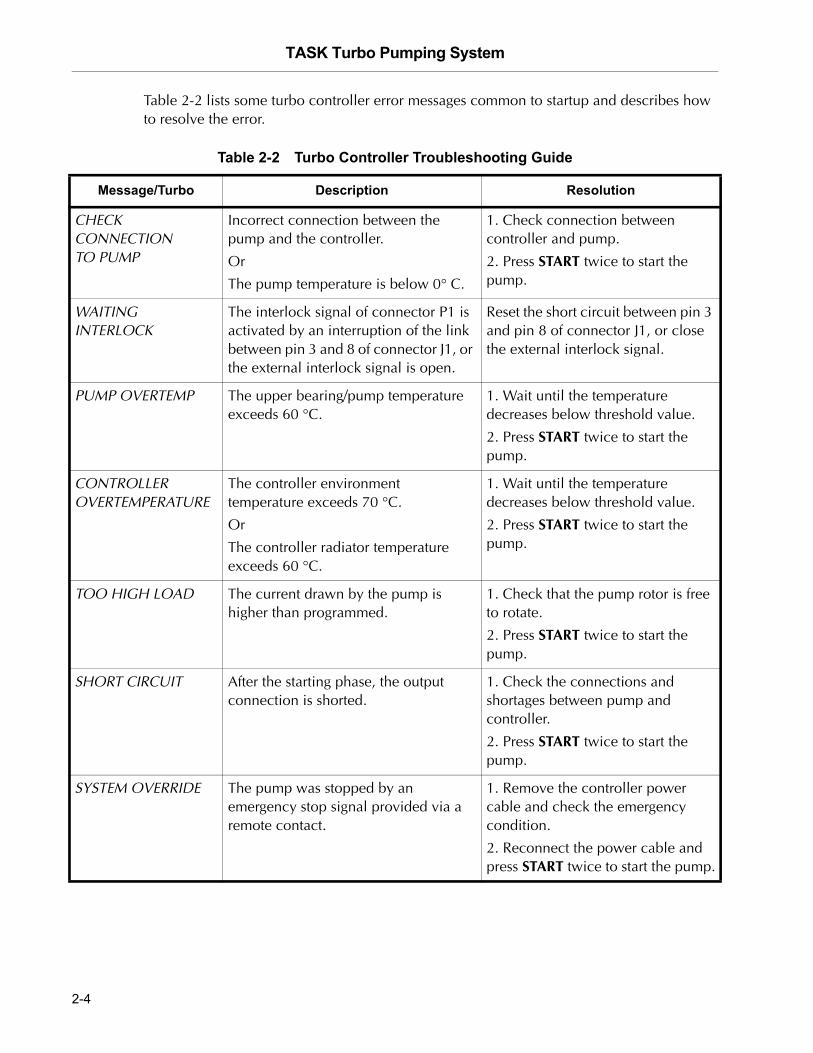
Table 2-2 lists some turbo controller error messages common to startup and describes how to resolve the error.
Table 2-2 Turbo Controller Troubleshooting Guide
Message/Turbo Description Resolution
CHECK CONNECTION TO PUMP
Incorrect connection between the pump and the controller.
Or
The pump temperature is below 0° C.
1. Check connection between controller and pump.
2. Press START twice to start the pump.
WAITING INTERLOCK
The interlock signal of connector P1 is activated by an interruption of the link between pin 3 and 8 of connector J1, or the external interlock signal is open.
Reset the short circuit between pin 3 and pin 8 of connector J1, or close the external interlock signal.
PUMP OVERTEMP The upper bearing/pump temperature exceeds 60 °C.
1. Wait until the temperature decreases below threshold value.
2. Press START twice to start the pump.
CONTROLLER OVERTEMPERATURE
The controller environment temperature exceeds 70 °C.
Or
The controller radiator temperature exceeds 60 °C.
1. Wait until the temperature decreases below threshold value.
2. Press START twice to start the pump.
TOO HIGH LOAD The current drawn by the pump is higher than programmed.
1. Check that the pump rotor is free to rotate.
2. Press START twice to start the pump.
SHORT CIRCUIT After the starting phase, the output connection is shorted.
1. Check the connections and shortages between pump and controller.
2. Press START twice to start the pump.
SYSTEM OVERRIDE The pump was stopped by an emergency stop signal provided via a remote contact.
1. Remove the controller power cable and check the emergency condition.
2. Reconnect the power cable and press START twice to start the pump.
2-4
TASK Turbo Pumping System
DR
AF
T 3
/26
/07
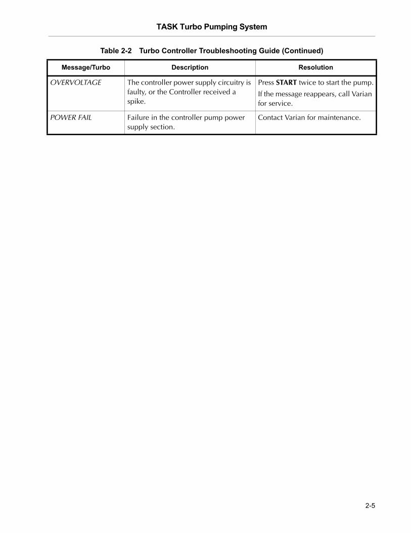
OVERVOLTAGE The controller power supply circuitry is faulty, or the Controller received a spike.
Press START twice to start the pump.
If the message reappears, call Varian for service.
POWER FAIL Failure in the controller pump power supply section.
Contact Varian for maintenance.
Table 2-2 Turbo Controller Troubleshooting Guide (Continued)
Message/Turbo Description Resolution
2-5
TASK Turbo Pumping System D
RA
FT
3/2
6/0
7
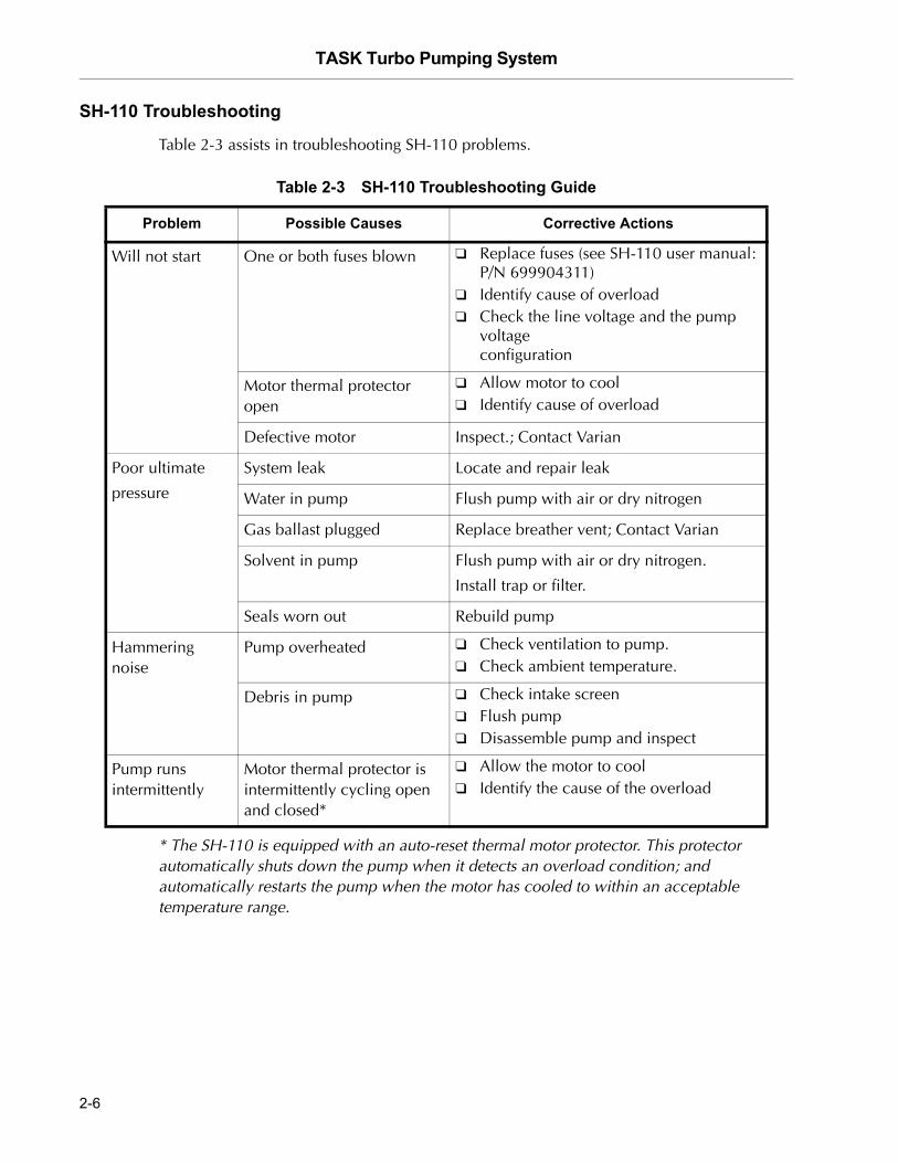
SH-110 Troubleshooting
Table 2-3 assists in troubleshooting SH-110 problems.
* The SH-110 is equipped with an auto-reset thermal motor protector. This protector automatically shuts down the pump when it detects an overload condition; and automatically restarts the pump when the motor has cooled to within an acceptable temperature range.
Table 2-3 SH-110 Troubleshooting Guide
Problem Possible Causes Corrective Actions
Will not start One or both fuses blown ❑ Replace fuses (see SH-110 user manual: P/N 699904311)
❑ Identify cause of overload❑ Check the line voltage and the pump
voltageconfiguration
Motor thermal protector open
❑ Allow motor to cool❑ Identify cause of overload
Defective motor Inspect.; Contact Varian
Poor ultimate
pressure
System leak Locate and repair leak
Water in pump Flush pump with air or dry nitrogen
Gas ballast plugged Replace breather vent; Contact Varian
Solvent in pump Flush pump with air or dry nitrogen.
Install trap or filter.
Seals worn out Rebuild pump
Hammering noise
Pump overheated ❑ Check ventilation to pump.❑ Check ambient temperature.
Debris in pump ❑ Check intake screen❑ Flush pump❑ Disassemble pump and inspect
Pump runs intermittently
Motor thermal protector is intermittently cycling open and closed*
❑ Allow the motor to cool❑ Identify the cause of the overload
2-6
TASK Turbo Pumping System
DR
AF
T 3
/26
/07
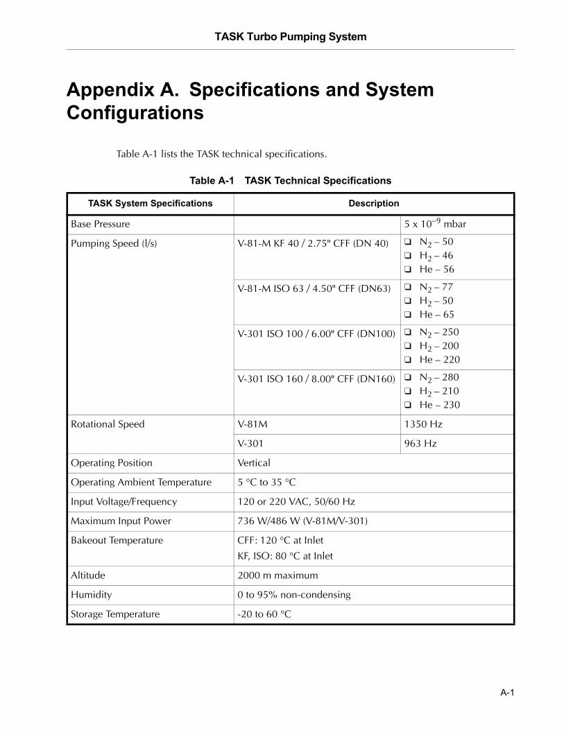
Appendix A. Specifications and System Configurations
Table A-1 lists the TASK technical specifications.
Table A-1 TASK Technical Specifications
TASK System Specifications Description
Base Pressure 5 x 10⁻⁹ mbar
Pumping Speed (l/s) V-81-M KF 40 / 2.75" CFF (DN 40) ❑ N2 – 50❑ H2 – 46❑ He – 56
V-81-M ISO 63 / 4.50" CFF (DN63) ❑ N2 – 77❑ H2 – 50❑ He – 65
V-301 ISO 100 / 6.00" CFF (DN100) ❑ N2 – 250❑ H2 – 200❑ He – 220
V-301 ISO 160 / 8.00" CFF (DN160) ❑ N2 – 280❑ H2 – 210❑ He – 230
Rotational Speed V-81M 1350 Hz
V-301 963 Hz
Operating Position Vertical
Operating Ambient Temperature 5 °C to 35 °C
Input Voltage/Frequency 120 or 220 VAC, 50/60 Hz
Maximum Input Power 736 W/486 W (V-81M/V-301)
Bakeout Temperature CFF: 120 °C at Inlet
KF, ISO: 80 °C at Inlet
Altitude 2000 m maximum
Humidity 0 to 95% non-condensing
Storage Temperature -20 to 60 °C
A-1
TASK Turbo Pumping System D
RA
FT
3/2
6/0
7
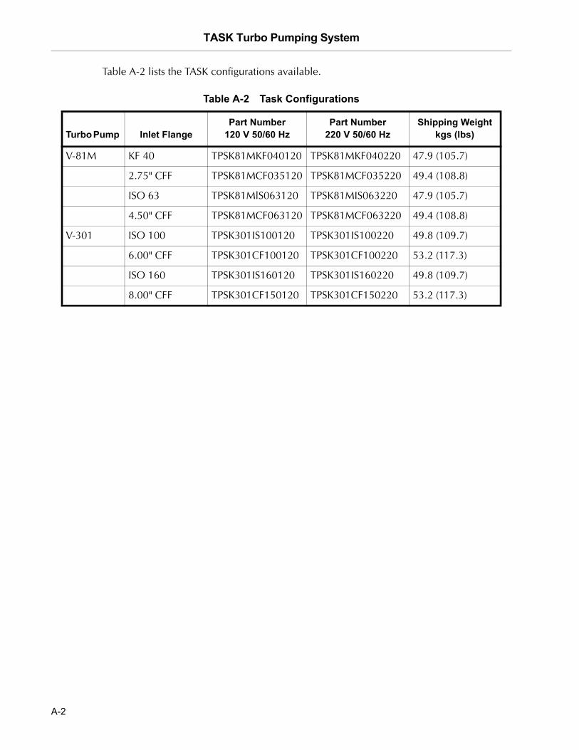
Table A-2 lists the TASK configurations available.
Table A-2 Task Configurations
Turbo Pump Inlet Flange Part Number
120 V 50/60 Hz Part Number
220 V 50/60 HzShipping Weight
kgs (lbs)
V-81M KF 40 TPSK81MKF040120 TPSK81MKF040220 47.9 (105.7)
2.75" CFF TPSK81MCF035120 TPSK81MCF035220 49.4 (108.8)
ISO 63 TPSK81MlS063120 TPSK81MIS063220 47.9 (105.7)
4.50" CFF TPSK81MCF063120 TPSK81MCF063220 49.4 (108.8)
V-301 ISO 100 TPSK301IS100120 TPSK301IS100220 49.8 (109.7)
6.00" CFF TPSK301CF100120 TPSK301CF100220 53.2 (117.3)
ISO 160 TPSK301IS160120 TPSK301IS160220 49.8 (109.7)
8.00" CFF TPSK301CF150120 TPSK301CF150220 53.2 (117.3)
A-2
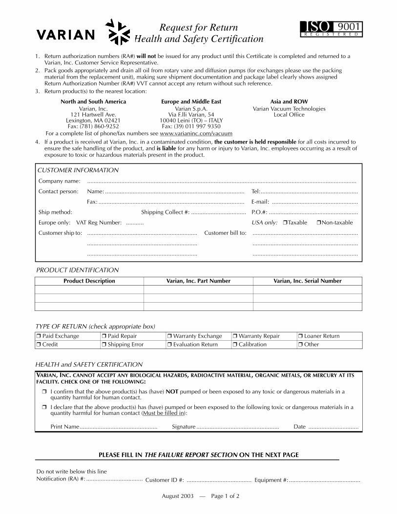
Request for Return Health and Safety Certification
1. Return authorization numbers (RA#) will not be issued for any product until this Certificate is completed and returned to a Varian, Inc. Customer Service Representative.
2. Pack goods appropriately and drain all oil from rotary vane and diffusion pumps (for exchanges please use the packing material from the replacement unit), making sure shipment documentation and package label clearly shows assigned Return Authorization Number (RA#) VVT cannot accept any return without such reference.
3. Return product(s) to the nearest location:
4. If a product is received at Varian, Inc. in a contaminated condition, the customer is held responsible for all costs incurred to ensure the safe handling of the product, and is liable for any harm or injury to Varian, Inc. employees occurring as a result of exposure to toxic or hazardous materials present in the product.
PLEASE FILL IN THE FAILURE REPORT SECTION ON THE NEXT PAGE
North and South America Europe and Middle East Asia and ROWVarian, Inc.
121 Hartwell Ave.Lexington, MA 02421Fax: (781) 860-9252
Varian S.p.A.Via F.lli Varian, 54
10040 Leini (TO) – ITALYFax: (39) 011 997 9350
Varian Vacuum TechnologiesLocal Office
For a complete list of phone/fax numbers see www.varianinc.com/vacuum
Do not write below this lineNotification (RA) #: ................................... Customer ID #: ........................................ Equipment #: ............................................
CUSTOMER INFORMATION
Company name: ......................................................................................................................................................................
Contact person: Name: ...................................................................................... Tel:............................................................
Fax: .......................................................................................... E-mail: .....................................................
Ship method: Shipping Collect #: .................................. P.O.#: .......................................................
Europe only: VAT Reg Number: ........... USA only: ❒Taxable ❒Non-taxable
Customer ship to: .................................................................... Customer bill to: .................................................................
.................................................................... .................................................................
.................................................................... .................................................................
PRODUCT IDENTIFICATION
Product Description Varian, Inc. Part Number Varian, Inc. Serial Number
TYPE OF RETURN (check appropriate box)❒ Paid Exchange ❒ Paid Repair ❒ Warranty Exchange ❒ Warranty Repair ❒ Loaner Return❒ Credit ❒ Shipping Error ❒ Evaluation Return ❒ Calibration ❒ Other
HEALTH and SAFETY CERTIFICATION
VARIAN, INC. CANNOT ACCEPT ANY BIOLOGICAL HAZARDS, RADIOACTIVE MATERIAL, ORGANIC METALS, OR MERCURY AT ITS FACILITY. CHECK ONE OF THE FOLLOWING:
❒ I confirm that the above product(s) has (have) NOT pumped or been exposed to any toxic or dangerous materials in aquantity harmful for human contact.
❒ I declare that the above product(s) has (have) pumped or been exposed to the following toxic or dangerous materials in a quantity harmful for human contact (Must be filled in):
Print Name................................................ Signature ................................................... Date ...............................
August 2003 — Page 1 of 2
ISOR E G I S T E R E D
9001
Request for Return Health and Safety Certification
Request for ReturnHealth and Safety Certification
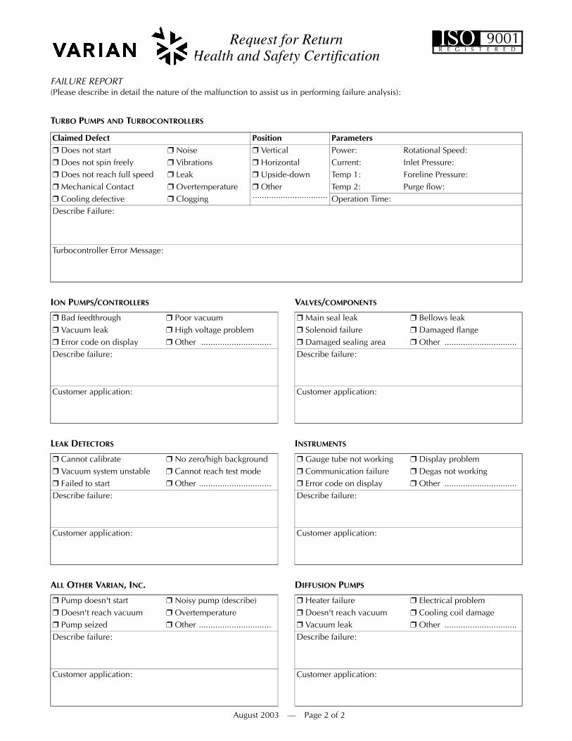
FAILURE REPORT (Please describe in detail the nature of the malfunction to assist us in performing failure analysis):
TURBO PUMPS AND TURBOCONTROLLERS
ION PUMPS/CONTROLLERS VALVES/COMPONENTS
LEAK DETECTORS INSTRUMENTS
ALL OTHER VARIAN, INC. DIFFUSION PUMPS
Claimed Defect Position Parameters❒ Does not start ❒ Noise ❒ Vertical Power: Rotational Speed:❒ Does not spin freely ❒ Vibrations ❒ Horizontal Current: Inlet Pressure:❒ Does not reach full speed ❒ Leak ❒ Upside-down Temp 1: Foreline Pressure:❒ Mechanical Contact ❒ Overtemperature ❒ Other
................................Temp 2: Purge flow:
❒ Cooling defective ❒ Clogging Operation Time:Describe Failure:
Turbocontroller Error Message:
❒ Bad feedthrough ❒ Poor vacuum ❒ Main seal leak ❒ Bellows leak❒ Vacuum leak ❒ High voltage problem ❒ Solenoid failure ❒ Damaged flange❒ Error code on display ❒ Other .............................. ❒ Damaged sealing area ❒ Other ...............................Describe failure: Describe failure:
Customer application: Customer application:
❒ Cannot calibrate ❒ No zero/high background ❒ Gauge tube not working ❒ Display problem❒ Vacuum system unstable ❒ Cannot reach test mode ❒ Communication failure ❒ Degas not working❒ Failed to start ❒ Other ............................... ❒ Error code on display ❒ Other ...............................Describe failure: Describe failure:
Customer application: Customer application:
❒ Pump doesn't start ❒ Noisy pump (describe) ❒ Heater failure ❒ Electrical problem❒ Doesn't reach vacuum ❒ Overtemperature ❒ Doesn't reach vacuum ❒ Cooling coil damage❒ Pump seized ❒ Other ............................... ❒ Vacuum leak ❒ Other ...............................Describe failure: Describe failure:
Customer application: Customer application:
August 2003 — Page 2 of 2
ISOR E G I S T E R E D
9001

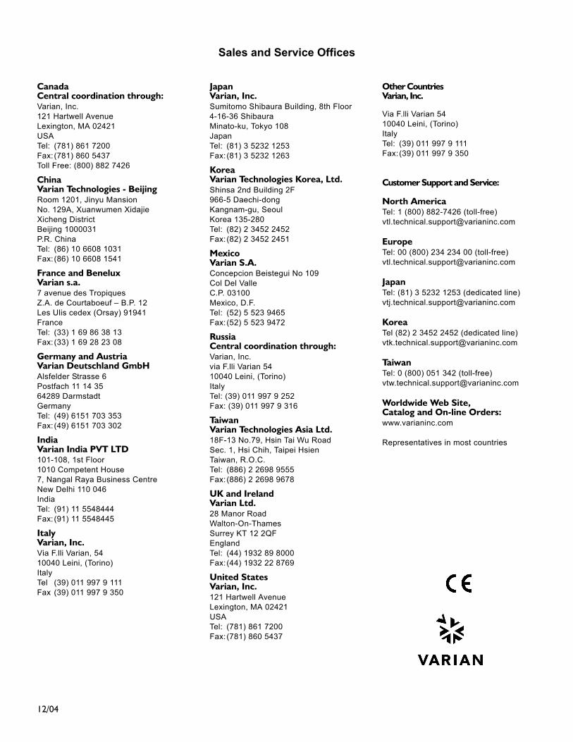
Sales and Service Offices
12/04
CanadaCentral coordination through:Varian, Inc.121 Hartwell AvenueLexington, MA 02421USATel: (781) 861 7200Fax: (781) 860 5437Toll Free: (800) 882 7426
ChinaVarian Technologies - BeijingRoom 1201, Jinyu MansionNo. 129A, Xuanwumen XidajieXicheng DistrictBeijing 1000031P.R. ChinaTel: (86) 10 6608 1031Fax: (86) 10 6608 1541
France and BeneluxVarian s.a.7 avenue des TropiquesZ.A. de Courtaboeuf – B.P. 12Les Ulis cedex (Orsay) 91941FranceTel: (33) 1 69 86 38 13Fax: (33) 1 69 28 23 08
Germany and AustriaVarian Deutschland GmbHAlsfelder Strasse 6Postfach 11 14 3564289 DarmstadtGermanyTel: (49) 6151 703 353Fax: (49) 6151 703 302
IndiaVarian India PVT LTD101-108, 1st Floor1010 Competent House7, Nangal Raya Business CentreNew Delhi 110 046IndiaTel: (91) 11 5548444Fax: (91) 11 5548445
ItalyVarian, Inc.Via F.lli Varian, 5410040 Leini, (Torino)ItalyTel (39) 011 997 9 111Fax (39) 011 997 9 350
JapanVarian, Inc.Sumitomo Shibaura Building, 8th Floor4-16-36 ShibauraMinato-ku, Tokyo 108JapanTel: (81) 3 5232 1253Fax: (81) 3 5232 1263
KoreaVarian Technologies Korea, Ltd.Shinsa 2nd Building 2F966-5 Daechi-dong Kangnam-gu, SeoulKorea 135-280Tel: (82) 2 3452 2452Fax: (82) 2 3452 2451
MexicoVarian S.A.Concepcion Beistegui No 109Col Del ValleC.P. 03100Mexico, D.F.Tel: (52) 5 523 9465Fax: (52) 5 523 9472
RussiaCentral coordination through:Varian, Inc.via F.lli Varian 5410040 Leini, (Torino)ItalyTel: (39) 011 997 9 252Fax: (39) 011 997 9 316
TaiwanVarian Technologies Asia Ltd. 18F-13 No.79, Hsin Tai Wu RoadSec. 1, Hsi Chih, Taipei HsienTaiwan, R.O.C.Tel: (886) 2 2698 9555Fax: (886) 2 2698 9678
UK and Ireland Varian Ltd.28 Manor RoadWalton-On-ThamesSurrey KT 12 2QFEnglandTel: (44) 1932 89 8000Fax: (44) 1932 22 8769
United StatesVarian, Inc.121 Hartwell AvenueLexington, MA 02421USATel: (781) 861 7200Fax: (781) 860 5437
Other CountriesVarian, Inc.
Via F.lli Varian 5410040 Leini, (Torino)ItalyTel: (39) 011 997 9 111Fax: (39) 011 997 9 350
Customer Support and Service:
North AmericaTel: 1 (800) 882-7426 (toll-free)[email protected]
EuropeTel: 00 (800) 234 234 00 (toll-free)[email protected]
JapanTel: (81) 3 5232 1253 (dedicated line)[email protected]
KoreaTel (82) 2 3452 2452 (dedicated line)[email protected]
TaiwanTel: 0 (800) 051 342 (toll-free)[email protected]
Worldwide Web Site, Catalog and On-line Orders:www.varianinc.com
Representatives in most countries
Sales and Service Offices
Related Documents