06117333 Chanwoo Kwon

Project P rogress R eport Hybrid System with ultracapacitor
Jan 01, 2016
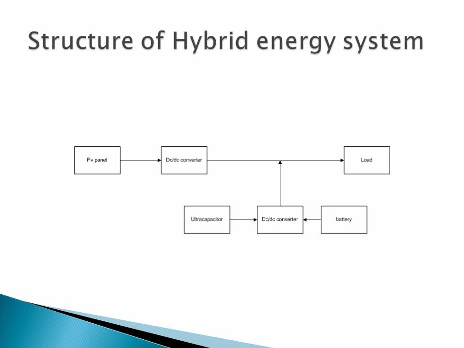
Project P rogress R eport Hybrid System with ultracapacitor. 06117333 Chanwoo Kwon. Project Aim. Model the ultracapacitor. Build a DC/DC Converter to charge the ultracapacitor from a 12V battery. Model a load such as a motor in Matlab/Simulink. Structure of Hybrid energy system. - PowerPoint PPT Presentation
Welcome message from author
This document is posted to help you gain knowledge. Please leave a comment to let me know what you think about it! Share it to your friends and learn new things together.
Transcript

06117333Chanwoo Kwon
Model the ultracapacitor.
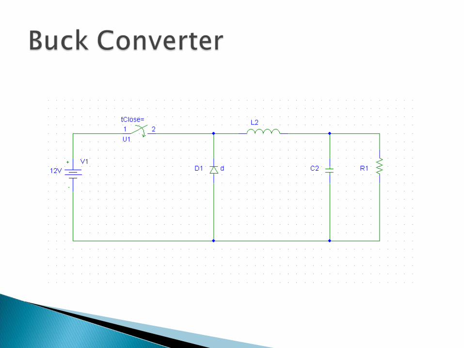
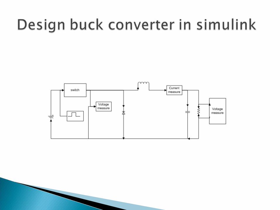
Build a DC/DC Converter to charge the ultracapacitor from a 12V battery.
Model a load such as a motor in Matlab/Simulink.

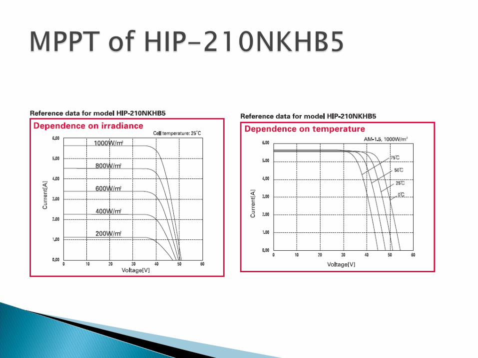
Model : HIP-210NKHB5 Cell efficieny: 18.9% Module efficiency:16.4%
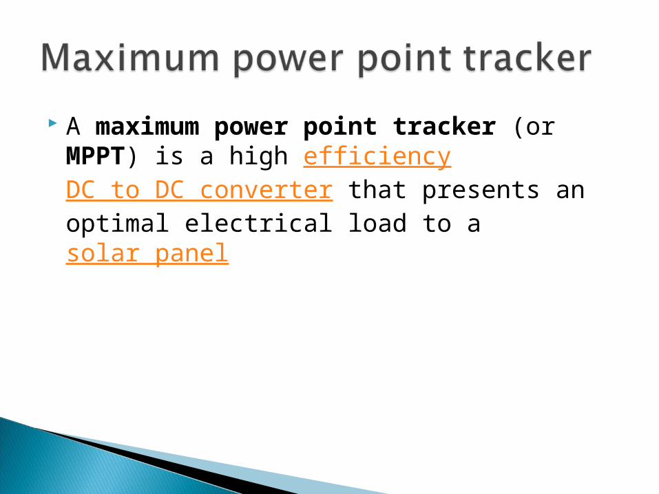
A maximum power point tracker (or MPPT) is a high efficiency DC to DC converter that presents an optimal electrical load to a solar panel
RC parallel branch model RC transmission line model RC series-parallel branch model

Each RC branch has a different time constant. The fast-term branch dominates the charge and discharge behavior in the
order of a few seconds. The medium-term branch dominates the behavior over the scale of
minutes. Finally the slow-term branch governs the long-term charge and discharge
characteristics.
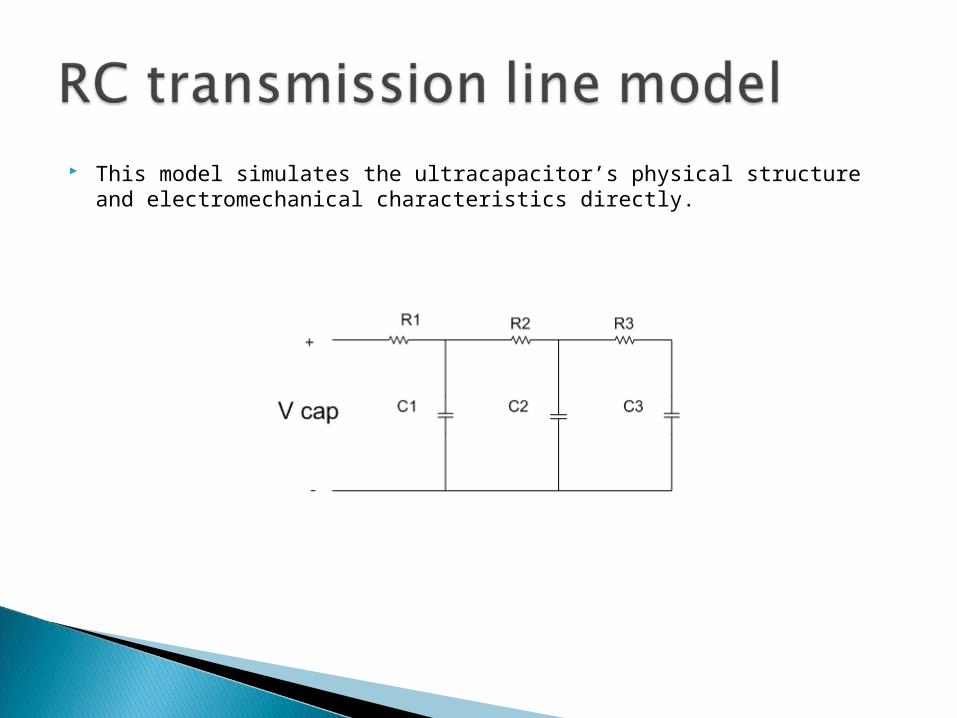
This model simulates the ultracapacitor’s physical structure and electromechanical characteristics directly.
RC parallel branch model reflects the internal charge distribution process very well.
Good response of the ultracap’s dynamic behavior during charging and discharging.
Accuracy is better and not complex.
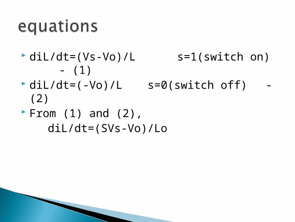
diL/dt=(Vs-Vo)/L s=1(switch on) - (1) diL/dt=(-Vo)/L s=0(switch off) - (2) From (1) and (2), diL/dt=(SVs-Vo)/Lo

Input voltage Vin=12V Output voltage Vout=2.7*3=8.1V Variation input voltage=+9¬15V R=10 L=0.3m C=0.2m Frequency=100khz -> T=1/100k=0.01 D=Vout/Vin=8.1/12=0.675


Decide a motor required high starting current and connect it with ultracapacitor model.
Decide each value such as inductor,capacitor,resistance to operate this motor efficiently.
Simulate a Simulink/MATLAB model of the complete system.
Related Documents