1 Project Levitate: Synopsis Leif Andersen Daniel Blakemore Jon Parker I. I NTRODUCTION The goal of Project Levitate is to create a quadrotor that is capable of autonomous flight and object tracking. A quadrotor is a flying robot with four vertical rotors centered around a control unit. Quadrotors tend to be more stable and easier to maneuver than traditional single rotor helicopters. With one rotor, the angle of the rotor must be adjusted to control speed and direction. Additionally, traditional helicopters need a tail rotor on an orthogonal axis to stabilize against the torque of the main rotor. With four rotors, the same control and stability can be achieved by just changing speeds on individual rotors with no angular adjustments. All of the hardware and software will be onboard the quadrotor, without any need to talk to an external computer. It will use a camera with very basic image recognition software to track objects tagged with a recognizable pattern similar to a barcode. There will also be some rudimentary autopilot software that will cause the quadrotor to follow the object being tracked, while not crashing into anything. If the quadrotor has lost the item it is tracking, it will simply hover, and eventually land. This will be achieved using an onboard gyroscope and accelerometer. The quadrotor will have a radio to control throttle primarily for safety and debugging. The quadrotor will not be pre-packaged, but instead will be a modified version of the quadrotor built in our prior Embedded Systems class. Some of the groups working with quadrotors are the Micro Autonomous Systems Technologies in the GRASP lab at the University of Pennsylvania with their Aggressive Maneuvers for Autonomous Quadrotor Flight video [1], and Raffaello DAndrea at the FRAC Center in Paris [2]. Both of these groups use motion capture for positioning, but the advanced uses of their robots demonstrate that quadrotors are adept platforms with room for self-contained automation. Jur Van Den Burg of the University of Utah Algorithmic Robotics Lab has a flight lab for quadrotors to which he is providing access, plus he and his grad students are serving as informational resources. II. QUADROTOR A quadrotor platform has already been constructed. It consists of eight-inch propellers mounted to four brushless DC motors [3]. Each rotor has 400g of thrust maximum, for a combined maximum platform thrust of 1.6kg. For good maneuverability, the motors should be at 50 Fig. 1. Preliminary quadrotor platform.

Welcome message from author
This document is posted to help you gain knowledge. Please leave a comment to let me know what you think about it! Share it to your friends and learn new things together.
Transcript

1Project Levitate: SynopsisLeif Andersen
Daniel BlakemoreJon Parker
I. INTRODUCTION
The goal of Project Levitate is to create a quadrotor that is capable of autonomous flight and object tracking.A quadrotor is a flying robot with four vertical rotors centered around a control unit. Quadrotors tend to be morestable and easier to maneuver than traditional single rotor helicopters. With one rotor, the angle of the rotor must beadjusted to control speed and direction. Additionally, traditional helicopters need a tail rotor on an orthogonal axisto stabilize against the torque of the main rotor. With four rotors, the same control and stability can be achievedby just changing speeds on individual rotors with no angular adjustments.
All of the hardware and software will be onboard the quadrotor, without any need to talk to an external computer.It will use a camera with very basic image recognition software to track objects tagged with a recognizable patternsimilar to a barcode. There will also be some rudimentary autopilot software that will cause the quadrotor tofollow the object being tracked, while not crashing into anything. If the quadrotor has lost the item it is tracking,it will simply hover, and eventually land. This will be achieved using an onboard gyroscope and accelerometer.The quadrotor will have a radio to control throttle primarily for safety and debugging. The quadrotor will not bepre-packaged, but instead will be a modified version of the quadrotor built in our prior Embedded Systems class.
Some of the groups working with quadrotors are the Micro Autonomous Systems Technologies in the GRASPlab at the University of Pennsylvania with their Aggressive Maneuvers for Autonomous Quadrotor Flight video [1],and Raffaello DAndrea at the FRAC Center in Paris [2]. Both of these groups use motion capture for positioning,but the advanced uses of their robots demonstrate that quadrotors are adept platforms with room for self-containedautomation. Jur Van Den Burg of the University of Utah Algorithmic Robotics Lab has a flight lab for quadrotorsto which he is providing access, plus he and his grad students are serving as informational resources.
II. QUADROTOR
A quadrotor platform has already been constructed. It consists of eight-inch propellers mounted to four brushlessDC motors [3]. Each rotor has 400g of thrust maximum, for a combined maximum platform thrust of 1.6kg. Forgood maneuverability, the motors should be at 50
Fig. 1. Preliminary quadrotor platform.

The quadrotor platform in Figure 1 was a rapid prototype and will be modified as part of this project. A newcarbon fiber frame will replace the pictured one (an AR Drone cross piece). This frame is lighter, stiffer, andlarger to accommodate all the sensors comfortably. The zip ties of the old platform will be replaced with properscrew-mounts. Acrylic will be laser cut and serve as the base to which the electronics will mount. These platformimprovements are necessary so that physical flight characteristics do not change due to the shifting of components.
III. HARDWARE
The hardware components of the quadrotor comprise of:• One SmartFusion Evaluation Kit [4]• Six range finders [5]• One inertial measurement unit (IMU)• One camera [6],• One radio
Fig. 2. General hardware block diagram.
A. SmartFusion Evaluation Kit
The SmartFusion Evaluation Kit is a microcontroller unit consisting of an ARM Cortex-M3 and 200k-gate FPGAplaced on a board with a mixed signal header and various other peripherals. The SmartFusion will serve as thecentral controller to read sensors and run software for the quadrotor. It has been chosen for the ease in whichC-code can be written for it, and because motor control with stabilization is very time sensitive so running that inparallel hardware that is written for the FPGA will result in the most stable flight. The SmartFusion has 256KB offlash, 64KB of SRAM, and 4.6KB of FPGA block RAM.
2

Fig. 3. SmartFusion Evaluation Kit.
B. Range Finders
Maxbotix LV-EZ1 ultrasonic range finders will be used to detect obstructions in the quadrotors path. Theserange finders were chosen for their price, and their simple pulse-width modulation (PWM) communication. TheSmartFusion FPGA makes interfacing with PWM simple, and costs less pins than alternative formats. One rangefinder was attached as part of the Embedded Systems final project, and drivers to read raw data from it have alreadybeen written. However, new FPGA hardware will replace these drivers. This hardware will pre-process the noisyoutput of the range finders and discard incorrect values before the software reads the data. These sensors can detectobjects from eight inches up to twenty feet away.
Fig. 4. Range finder.
C. Camera
The chosen camera is a TCM8230D. It outputs 640x480 16-bit color frames at 30 frames-per-second. It wasselected for its small size and low price. Since the SmartFusion has limited RAM, some pre-processing of theimage must be performed before saving it into a frame buffer; this pre-processing will scale the image down to3-bit black-and-white at 320x240. This means the frame buffer only needs to be 28.8KB. Figure 5 illustrates theresults of the scaling on a typical image:
3
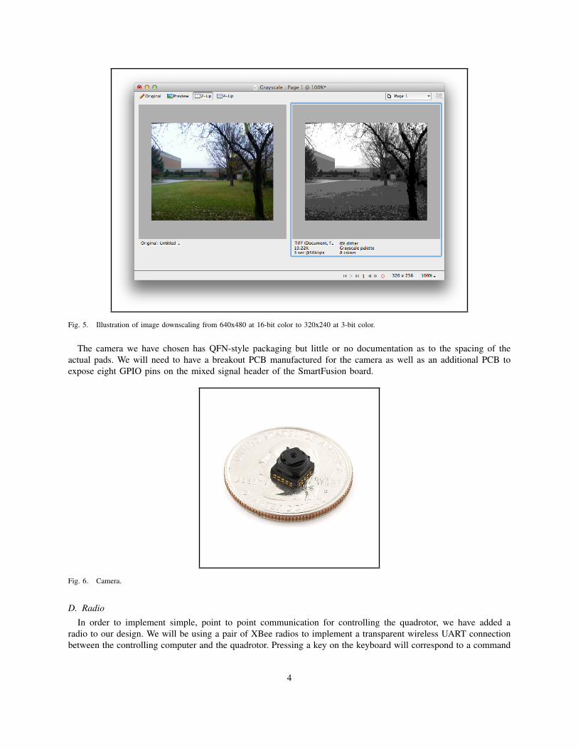
Fig. 5. Illustration of image downscaling from 640x480 at 16-bit color to 320x240 at 3-bit color.
The camera we have chosen has QFN-style packaging but little or no documentation as to the spacing of theactual pads. We will need to have a breakout PCB manufactured for the camera as well as an additional PCB toexpose eight GPIO pins on the mixed signal header of the SmartFusion board.
Fig. 6. Camera.
D. Radio
In order to implement simple, point to point communication for controlling the quadrotor, we have added aradio to our design. We will be using a pair of XBee radios to implement a transparent wireless UART connectionbetween the controlling computer and the quadrotor. Pressing a key on the keyboard will correspond to a command
4
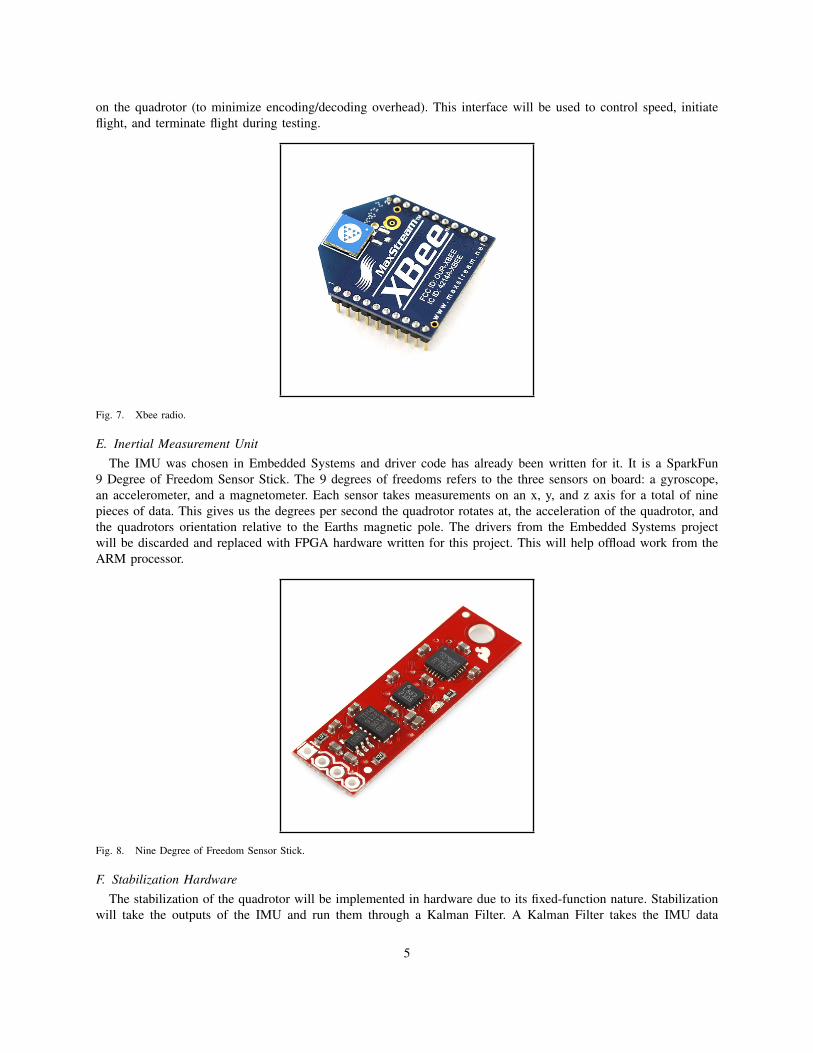
on the quadrotor (to minimize encoding/decoding overhead). This interface will be used to control speed, initiateflight, and terminate flight during testing.
Fig. 7. Xbee radio.
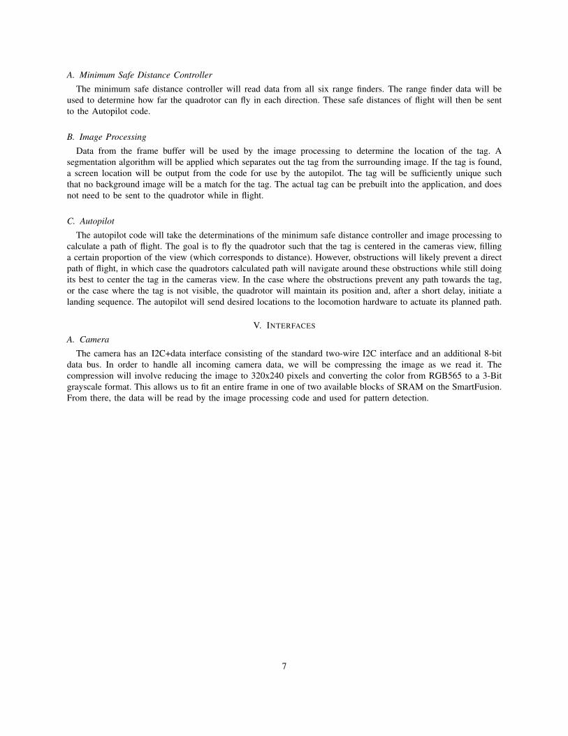
E. Inertial Measurement UnitThe IMU was chosen in Embedded Systems and driver code has already been written for it. It is a SparkFun
9 Degree of Freedom Sensor Stick. The 9 degrees of freedoms refers to the three sensors on board: a gyroscope,an accelerometer, and a magnetometer. Each sensor takes measurements on an x, y, and z axis for a total of ninepieces of data. This gives us the degrees per second the quadrotor rotates at, the acceleration of the quadrotor, andthe quadrotors orientation relative to the Earths magnetic pole. The drivers from the Embedded Systems projectwill be discarded and replaced with FPGA hardware written for this project. This will help offload work from theARM processor.
Fig. 8. Nine Degree of Freedom Sensor Stick.
F. Stabilization HardwareThe stabilization of the quadrotor will be implemented in hardware due to its fixed-function nature. Stabilization
will take the outputs of the IMU and run them through a Kalman Filter. A Kalman Filter takes the IMU data
5

and converts it into orientation (pitch, yaw, and roll). Then, a PID (proportion integral derivative) controller willset the individual motor speeds to keep the quadrotor level. A PID controller uses the error in the quadrotorscurrent orientation from its desired orientation. By taking the derivative and integral of this error in real time, andmultiplying these by fixed constants, speeds of the motors can be set that will eventually stabilize the quadrotor tothe desired orientation. Each axis of orientation and the error from it can and will be processed independently tosimplify the math. Additionally, the position determined by a down facing range finder will be used as the inputto another PID controller to adjust the height of the quadrotor to a desired height.
G. LocomotionLocomotion is an extension of the stabilization hardware. It will take a desired (x,y,z) position relative to the
current location as an input and fly there using more PID controllers. Essentially it is just modifying an equilibriumpoint for the stabilization to reach.
IV. SOFTWARE
The software will include three modules:• Minimum Safe Distance Controller• Image Processing• Autopilot
The purpose of these modules is to look for a tagged target, scan for possible obstructions, and then calculate apath of flight that best follows the tagged target.
Fig. 9. General software block diagram.
6
A. Minimum Safe Distance Controller
The minimum safe distance controller will read data from all six range finders. The range finder data will beused to determine how far the quadrotor can fly in each direction. These safe distances of flight will then be sentto the Autopilot code.
B. Image Processing
Data from the frame buffer will be used by the image processing to determine the location of the tag. Asegmentation algorithm will be applied which separates out the tag from the surrounding image. If the tag is found,a screen location will be output from the code for use by the autopilot. The tag will be sufficiently unique suchthat no background image will be a match for the tag. The actual tag can be prebuilt into the application, and doesnot need to be sent to the quadrotor while in flight.
C. Autopilot
The autopilot code will take the determinations of the minimum safe distance controller and image processing tocalculate a path of flight. The goal is to fly the quadrotor such that the tag is centered in the cameras view, fillinga certain proportion of the view (which corresponds to distance). However, obstructions will likely prevent a directpath of flight, in which case the quadrotors calculated path will navigate around these obstructions while still doingits best to center the tag in the cameras view. In the case where the obstructions prevent any path towards the tag,or the case where the tag is not visible, the quadrotor will maintain its position and, after a short delay, initiate alanding sequence. The autopilot will send desired locations to the locomotion hardware to actuate its planned path.
V. INTERFACES
A. Camera
The camera has an I2C+data interface consisting of the standard two-wire I2C interface and an additional 8-bitdata bus. In order to handle all incoming camera data, we will be compressing the image as we read it. Thecompression will involve reducing the image to 320x240 pixels and converting the color from RGB565 to a 3-Bitgrayscale format. This allows us to fit an entire frame in one of two available blocks of SRAM on the SmartFusion.From there, the data will be read by the image processing code and used for pattern detection.
7
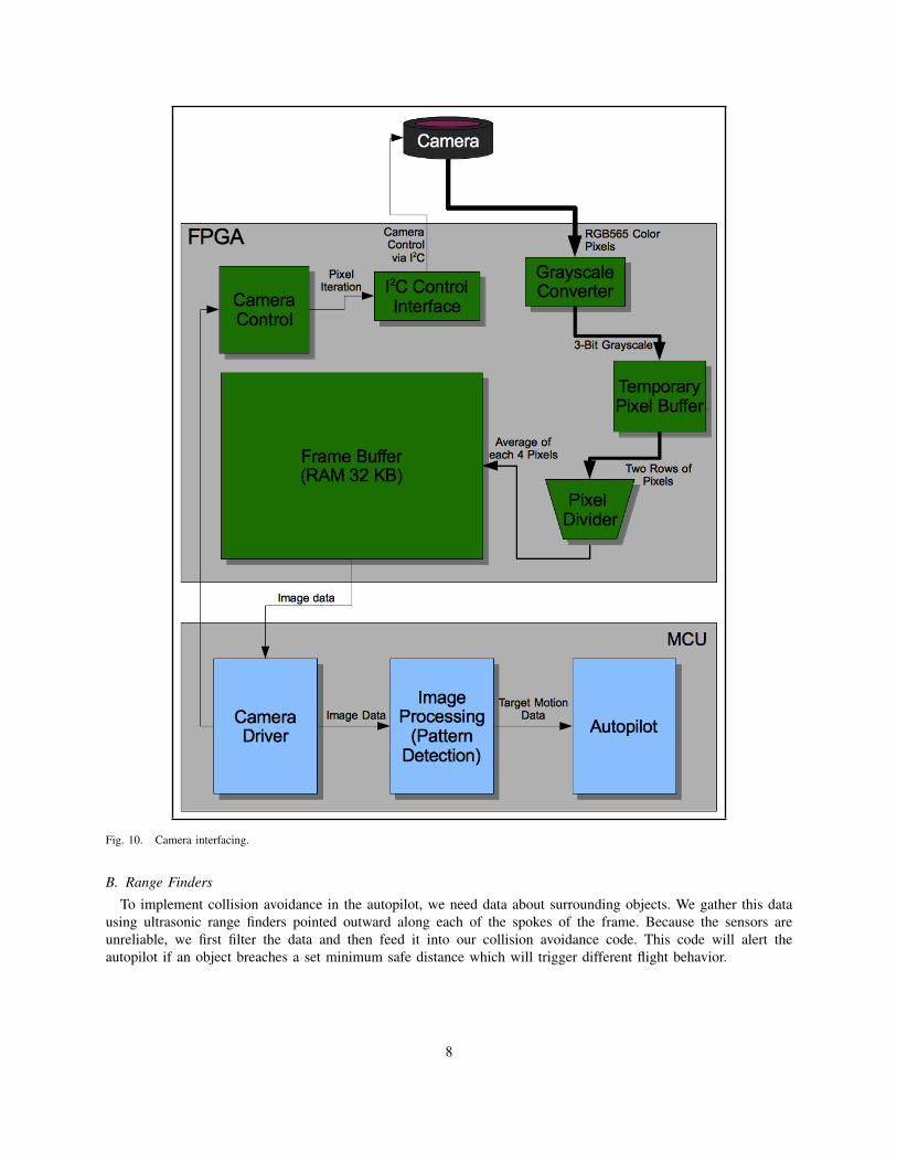
Fig. 10. Camera interfacing.
B. Range Finders
To implement collision avoidance in the autopilot, we need data about surrounding objects. We gather this datausing ultrasonic range finders pointed outward along each of the spokes of the frame. Because the sensors areunreliable, we first filter the data and then feed it into our collision avoidance code. This code will alert theautopilot if an object breaches a set minimum safe distance which will trigger different flight behavior.
8

Fig. 11. Range finder interfacing.
C. Stabilization: IMU and Motors
The data from the IMU is not useful in its raw state. We would like to write a feedback loop on yaw, pitch, androll to stabilize the quadrotor during flight. The yaw, pitch, and roll data will be computed in hardware using aKalman filter. Then, also in hardware, it will be fed to a PID controller which will combine locomotion commandsfrom the autopilot with stabilization data resulting in stable flight based on autopilot input.
9

Fig. 12. Interfacing for the motors, IMU, stabilization, and locomotion to autopilot.
D. Software Flight Loop
Figure 13 displays the software run loop based on the autopilot model:
10
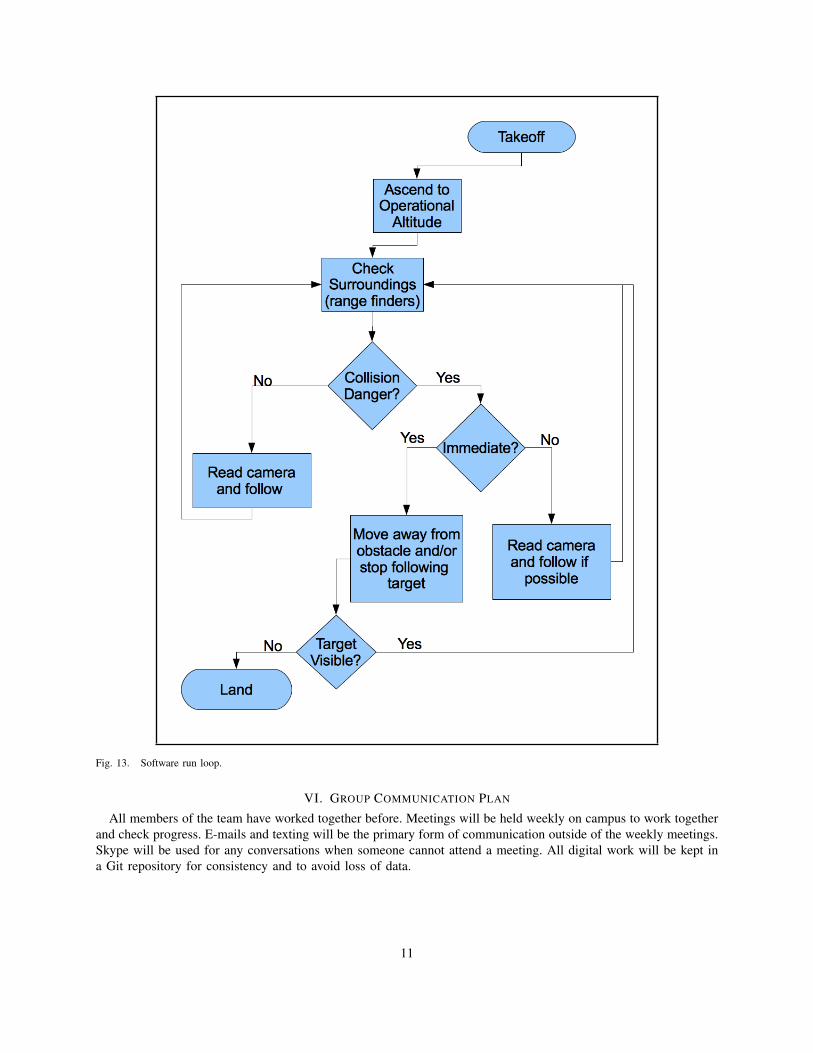
Fig. 13. Software run loop.
VI. GROUP COMMUNICATION PLAN
All members of the team have worked together before. Meetings will be held weekly on campus to work togetherand check progress. E-mails and texting will be the primary form of communication outside of the weekly meetings.Skype will be used for any conversations when someone cannot attend a meeting. All digital work will be kept ina Git repository for consistency and to avoid loss of data.
11
VII. SCHEDULE AND MILESTONES
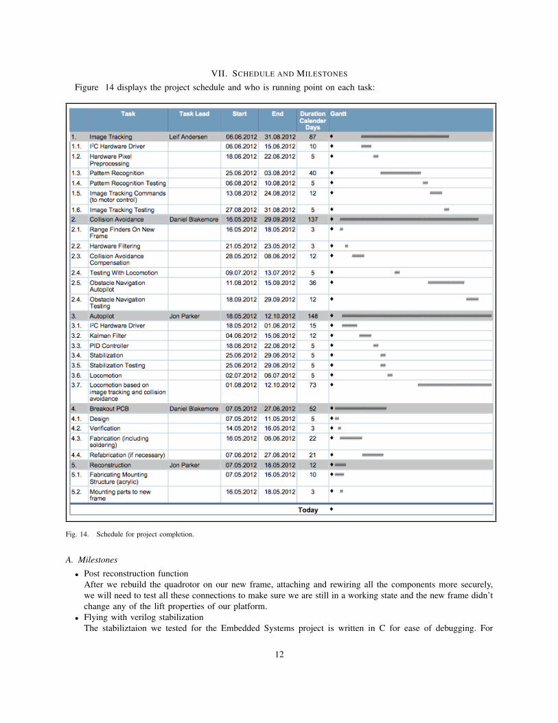
Figure 14 displays the project schedule and who is running point on each task:
Fig. 14. Schedule for project completion.
A. Milestones
• Post reconstruction functionAfter we rebuild the quadrotor on our new frame, attaching and rewiring all the components more securely,we will need to test all these connections to make sure we are still in a working state and the new frame didn’tchange any of the lift properties of our platform.
• Flying with verilog stabilizationThe stabiliztaion we tested for the Embedded Systems project is written in C for ease of debugging. For
12
performance reasons, the stabilization for this project will be implemented in the FPGA. Once this is done,we should be able to demo stabilization after this change.
• Controlled locomotion in arbitrary directionsWith the stabilization written, we should be able to demonstrate the ability to move in a specific directionwithout losing too much altitude or crashing.
• Radio controlled locomotionSimilar to above, except the movement commands are issued via radio.
• Locomotion stopping for obstructionsOnce the collision avoidance is complete, we should be able to move in a given direction, but stop when wesense an object too close.
• Locomotion navigating around obstructionsIf the quadrotor is moving in a certain direction, it should be able to move around an obstacle and continuemoving.
• Reacting to an image changeTo test the camera is feeding correcting into the autopilot, simply reacting to a change in what the camerasees is a good milestone.
• React only to a patternDetecting and reacting to a pattern but not to any other movement is important to demonstrate the imageprocessing section of the project.
• Follow a patternMoving along with a pattern attached to an object is the final milestone of the project and will be what wepresent on demo day.
VIII. TESTING AND INTEGRATION
Testing and integration will be conducted in line with development as illustrated by the schedule. We will bemaking extensive use of the SmartFusions convenient UArt output system which supports the printf function to adesktop console. The electrical and motor system has already been tested as part of the Embedded Systems project.Specific parts will be tested and integrated as follows:
• IMU and Kalman FilterThe IMU has already been tested as part of the Embedded Systems project. Since it must be rewritten to workin hardware, it will be retested by printing output values to the console as we physically move the IMU. Oncethe data looks accurate we will pass it through the Kalman filter and see if the Kalman filters outputs matchthe current orientation of the platform.
• Range findersThe range finders were already tested as part of the Embedded Systems project, but their drivers will beconverted into FPGA hardware that filters the data. A console app that displays measured distances will beused to test the range finders.
• Minimum safe distance controllerThe minimum safe distance controller is a simple software extension of the range finders, so once the rangefinders have been tested, they will be integrated with the minimum safe distance controller. Then we can testthis out on the quadrotor platform, physically holding the platform and moving it around while printing theoutputs of the safe distance controller to the console to check that values are valid.
• CameraTo test the camera, we will write software that outputs the frame buffer to a console. Then we will save thatdata as a text file. We will write code to display that file as an image on a desktop display to verify cameraoperation.
• Image processingTesting image processing will require specific test images at first. We will populate the frame buffer with theseimages and run the segmentation algorithm. Then we can print to console the resulting location of the imageand determine if this matches the expected result from the test pattern.
13
• Radio The radio transmitter plugs into a laptops USB port. To test it, we will print out the messages receivedby the SmartFusions radio to the console. Once this works, we will integrate the radio communication so thatit can set the maximum legal thrust in the stabilization software up and down. This ensures we have a safetycutoff once we start testing quadrotor flight.
• Stabilization and locomotionStabilization and locomotion will be verified first by tethering the quadrotor and ensuring that tilting thequadrotor or hard-coding specific locomotion destinations results in the right motors speeding up while othersslow down. Then we will keep the quadrotor tethered but give it some slack to see if it immediately destabilizesor not. The final stage is to get it into the flight room and let it free.
• AutopilotThe first test of autopilot software will use hard-coded fake obstruction and image data to check if the quadrotorcan really avoid flying to certain places by carrying it around and reading console output from a laptop. Oncethis is in place, those same hard-coded values will be used with integrated locomotion hardware. The quadrotorwill actually be tested in the flight room to see if it tries to avoid the hard-coded location. Finally, the imageprocessing and minimum safe distance controller will be integrated into the autopilot code and the quadrotorwill be flown in the flight room. Upon success, this will mark completion of the core project.
IX. RISK ASSESSMENT
A. Range Finders
A potential problem with range finders is false positives or false negatives in object detection. We lack experiencewith range finders and will need to experiment with how they are mounted on the chassis and how they actuallyfunction in order to get a better idea of what kind of behavior we can expect out of them in software. If necessary,we may add additional instrumentation to help in detecting objects which the range finders miss such as extra rangefinders or different sensors.
B. Camera
Since we have never written camera software or used cameras as more than an end user, we will need to startworking early to avoid finding that we have been working in the wrong direction and running out of time. Anotherrisk is fidelity. Since were reducing the image down to a low resolution and only eight distinct levels of brightness,our tag must be large. If the tag gets too far from the camera, it will likely be indistinguishable.
C. AI, Collision Avoidance, and Simulator
The autopilot using image processing and collision avoidance software is the core of our project and will involvea lot of computation. If it turns out that the Cortex M3 on the AF2 cannot run the code quickly enough we mayneed to upgrade hardware or make accuracy sacrifices in our software to compensate. Another big risk is the lackof understanding of math involved in collision avoidance and image processing for object tracking. We will contactpeople experienced with these subjects, specifically Jur van den Berg’s lab.
D. Safety
Physical risk is prominent in this project, both to people and to the hardware. The quadrotor blades can easilycut skin. If the quadrotor crashes, it could break the electronics, propellers, or the frame. Jur Van Den Burg hasgiven preliminary permission to use his flight room in conjunction with his grad students. Also, much of the flightcan be tested while the quadrotor is tethered down. Eye protection will be worn at all times.
14

X. BILL OF MATERIALS
Fig. 15. Bill of Materials
XI. BELLS AND WHISTLES
If tasks are completed earlier than scheduled and everything works without bugs, there are several ideas on howwe can expand this project to be even cooler:
• Seek ModeAn augmentation to the autopilot which will try to find the image if it is not visible on camera. This wouldrequire spinning around to look for the image, and flying to the last known location of the image and thenspiraling outwards to search.
• Quadrotor PongA game where the quadrotor flies towards a wall until it determines a collision would happen, at which pointit changes flight direction to mimic a pong ball bouncing off the wall. Tags would be used as paddles so if itsees that the tag is in front of it when it approaches, the ball is still in play.
• Radio ControlThe radio for the core of the project is only intended as a safety mechanism to shut off the quadrotor. However,we can potentially expand this to override the autopilot and allow for user control of the quadrotor.
XII. CONCLUSION
Ideally this quadrotor will demonstrate safe, indoor, stable flight that can track a tagged person by the end of fallsemester. If this is the case, the final demonstration will be a live flight demonstration down a hallway. Given thepossibility of damage, video will be recorded of successful flight to guarantee some demonstration. There is thepossibility that permission for a live demonstration will be denied due to safety concerns, in which case the videowill function as the demonstration.
REFERENCES
[1] http://www.youtube.com/watch?v=MvRTALJp8DM.[2] http://spectrum.ieee.org/automaton/robotics/diy/video-watch-flying-robots-build-a-6-meter-tower.[3] http://www.hobbyking.com/hobbyking/store/uh viewItem.asp?idProduct=2069.[4] http://www.actel.com/documents/A2F EVAL KIT UG.pdf.[5] http://www.maxbotix.com/products/MB1010.htm.[6] http://www.sparkfun.com/products/8667.
15
Related Documents