Welcome message from author
This document is posted to help you gain knowledge. Please leave a comment to let me know what you think about it! Share it to your friends and learn new things together.
Transcript


Prestressed Concrete Hollow Core Units
Flexural strength and deflections
Dr Kim S Elliott, UK
IPHA Technical Seminar – Tallinn – 25-26 October 2017

Precast Concrete Structures 2 nd ed.
700 pages with about 200 pages on precast floors

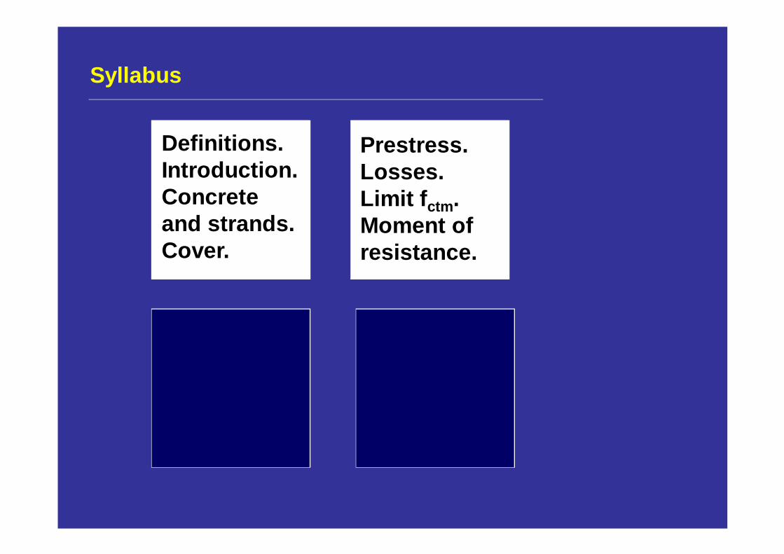
Syllabus
Definitions.Introduction.Concrete and strands.Cover.
Syllabus
Definitions.Introduction.Concrete and strands.Cover.
Prestress.Losses.Limit f ctm .Moment ofresistance.
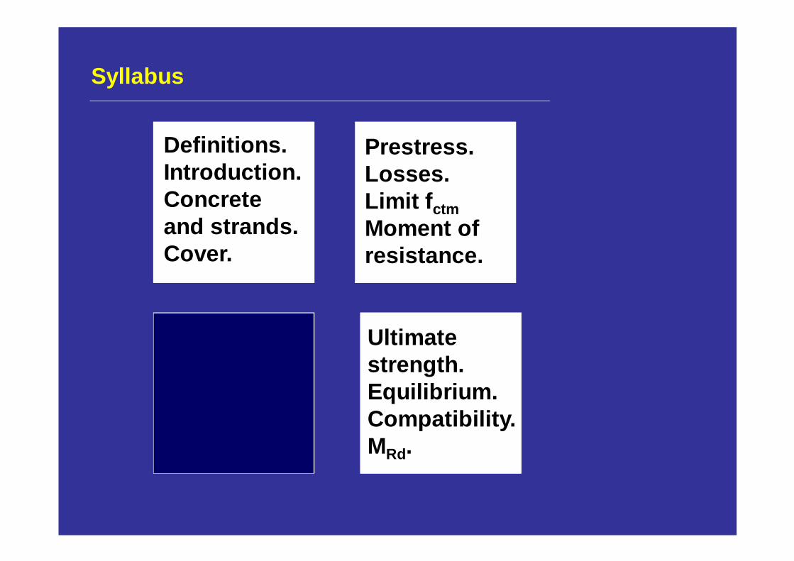
Syllabus
Definitions.Introduction.Concrete and strands.Cover.
Prestress.Losses.Limit f ctmMoment ofresistance.
Ultimate strength.Equilibrium.Compatibility.MRd.
Syllabus
Definitions.Introduction.Concrete and strands.Cover.
Prestress.Losses.Limit f ctmMoment ofresistance.
Ultimate strength.Equilibrium.CompatibilityMRd
Camber.Creep.Deflections.Limits.
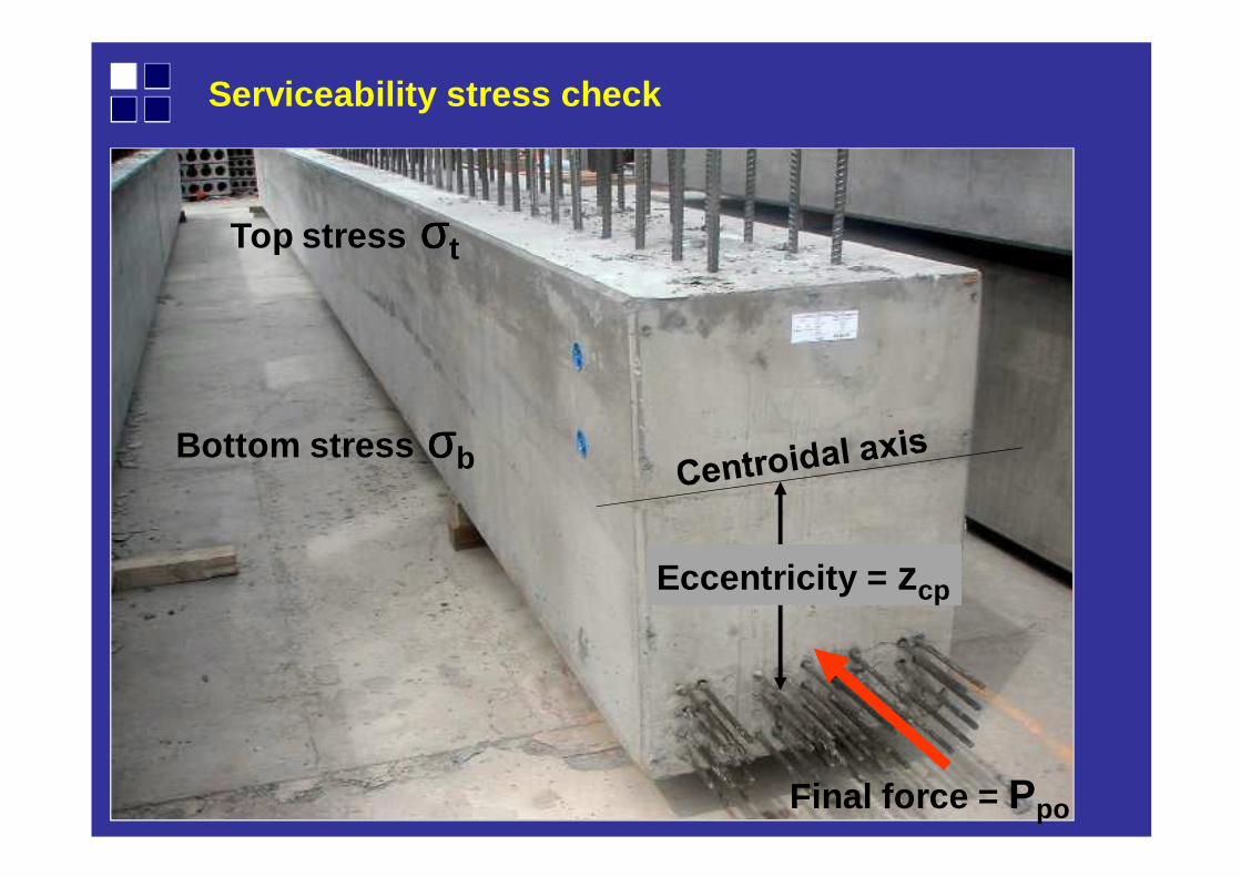
Bottom stress σσσσb
Top stress σσσσt
Eccentricity = zcp
Final force = Ppo
Serviceability stress check
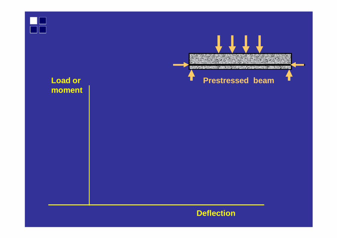
Load or moment
Deflection
Prestressed beam
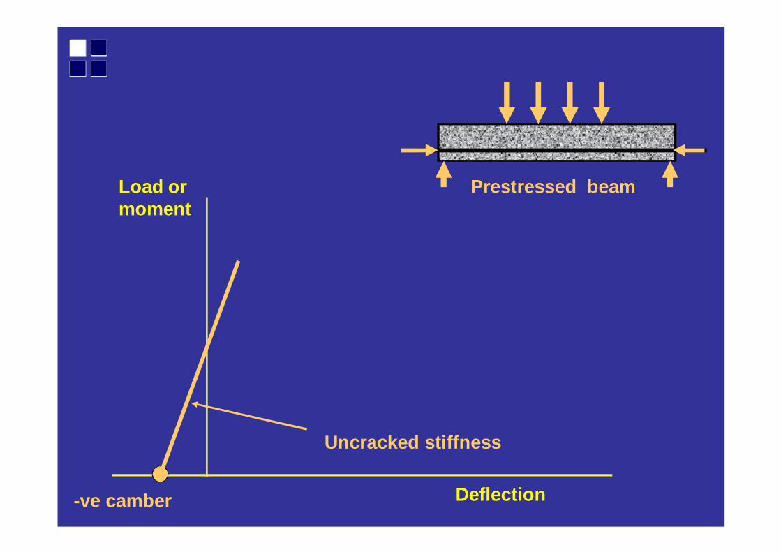
Load or moment
Deflection-ve camber
Uncracked stiffness
Prestressed beam
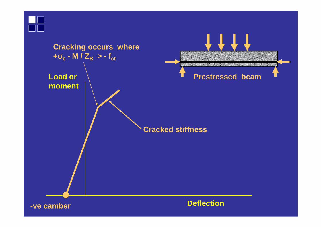
Load or moment
Deflection
Prestressed beam
Cracked stiffness
-ve camber
Cracking occurs where +σσσσb - M / ZB > - fct
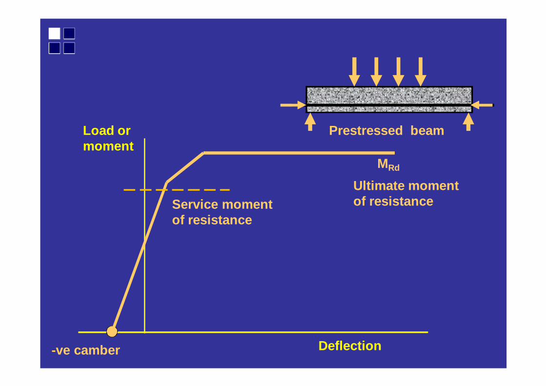
Load or moment
Deflection
Service moment of resistance
MRd
-ve camber
Prestressed beam
Ultimate moment of resistance
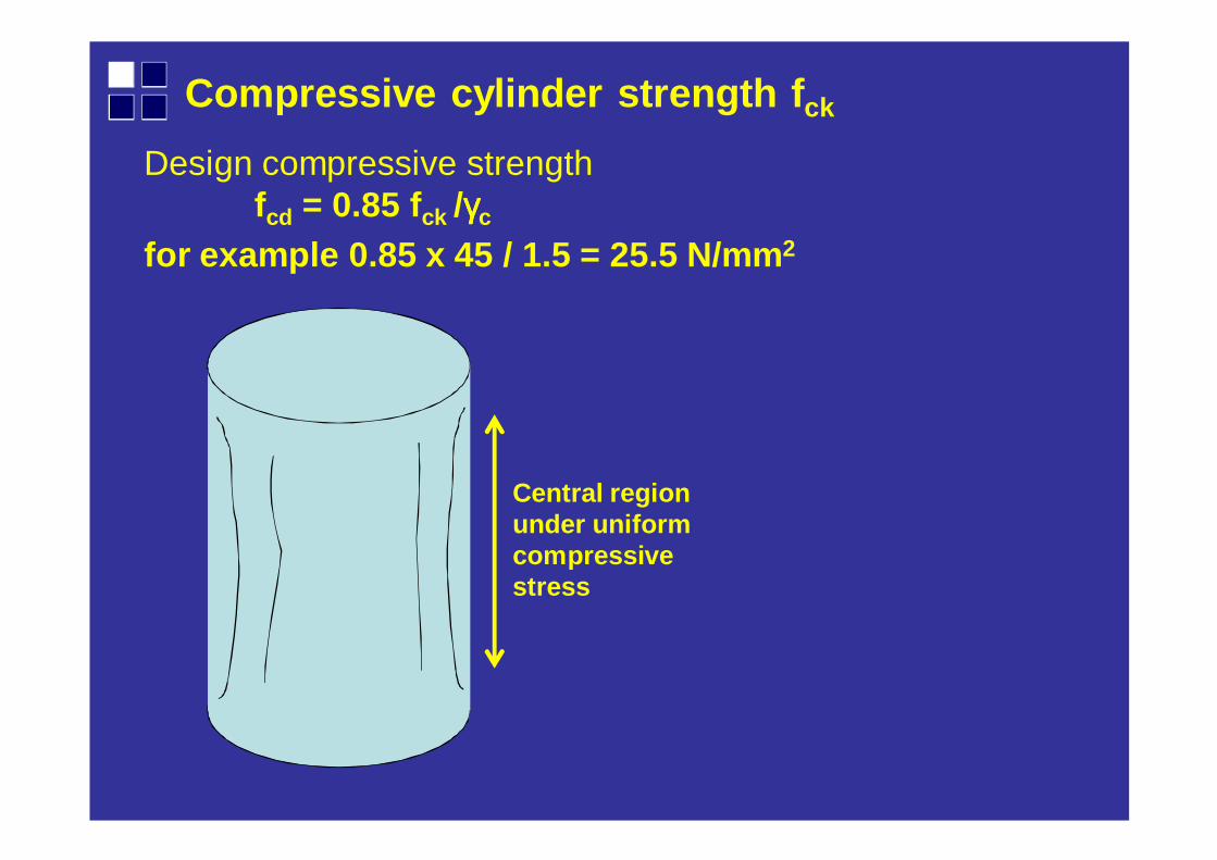
Compressive cylinder strength f ck
Central region under uniform compressive stress
Design compressive strengthfcd = 0.85 fck /γγγγc
for example 0.85 x 45 / 1.5 = 25.5 N/mm 2
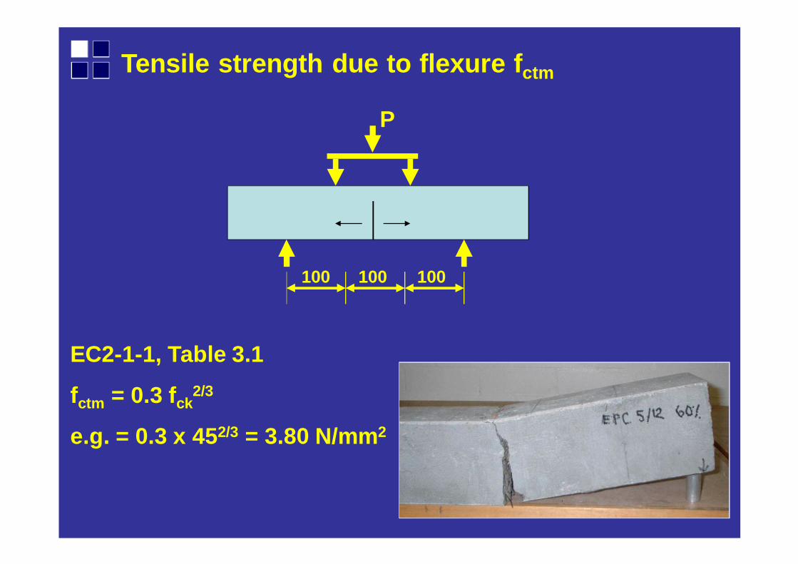
Tensile strength due to flexure f ctm
100 100 100
P
EC2-1-1, Table 3.1
fctm = 0.3 fck2/3
e.g. = 0.3 x 45 2/3 = 3.80 N/mm2
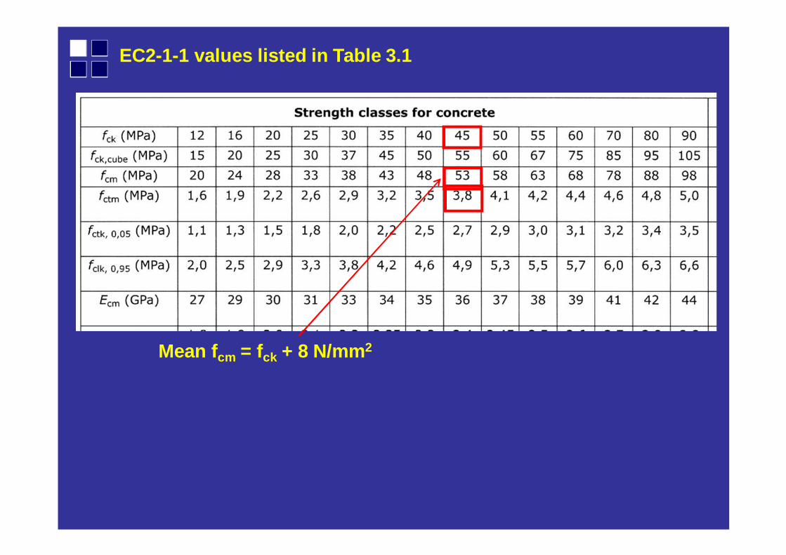
EC2-1-1 values listed in Table 3.1
Mean f cm = fck + 8 N/mm2
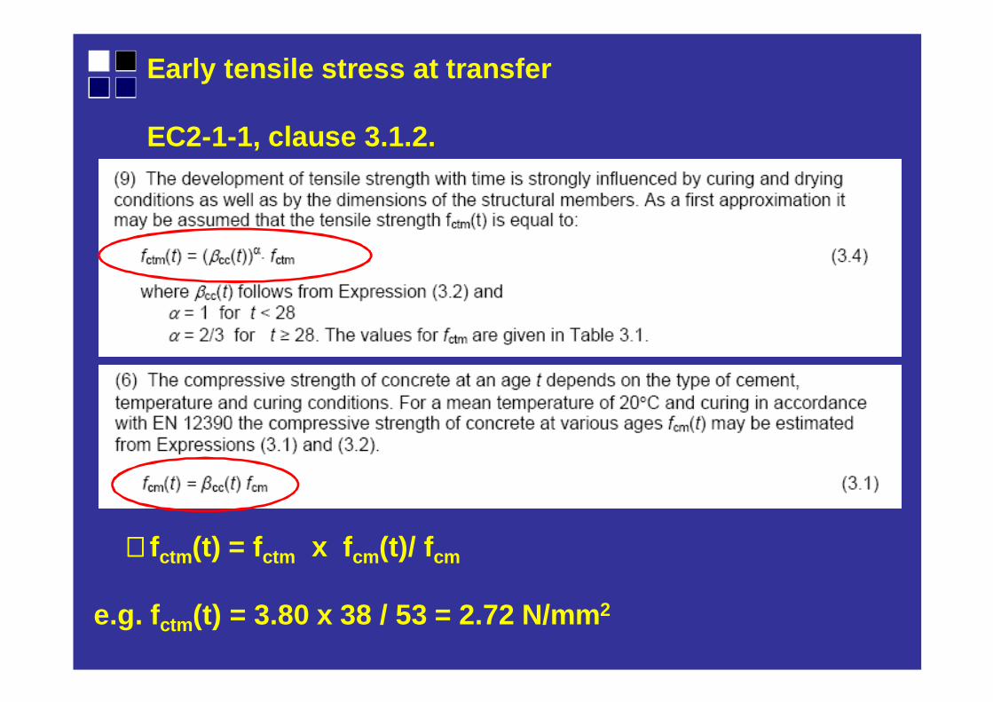
Early tensile stress at transfer
EC2-1-1, clause 3.1.2.
∴∴∴∴fctm (t) = f ctm x f cm(t)/ f cm
e.g. f ctm (t) = 3.80 x 38 / 53 = 2.72 N/mm 2
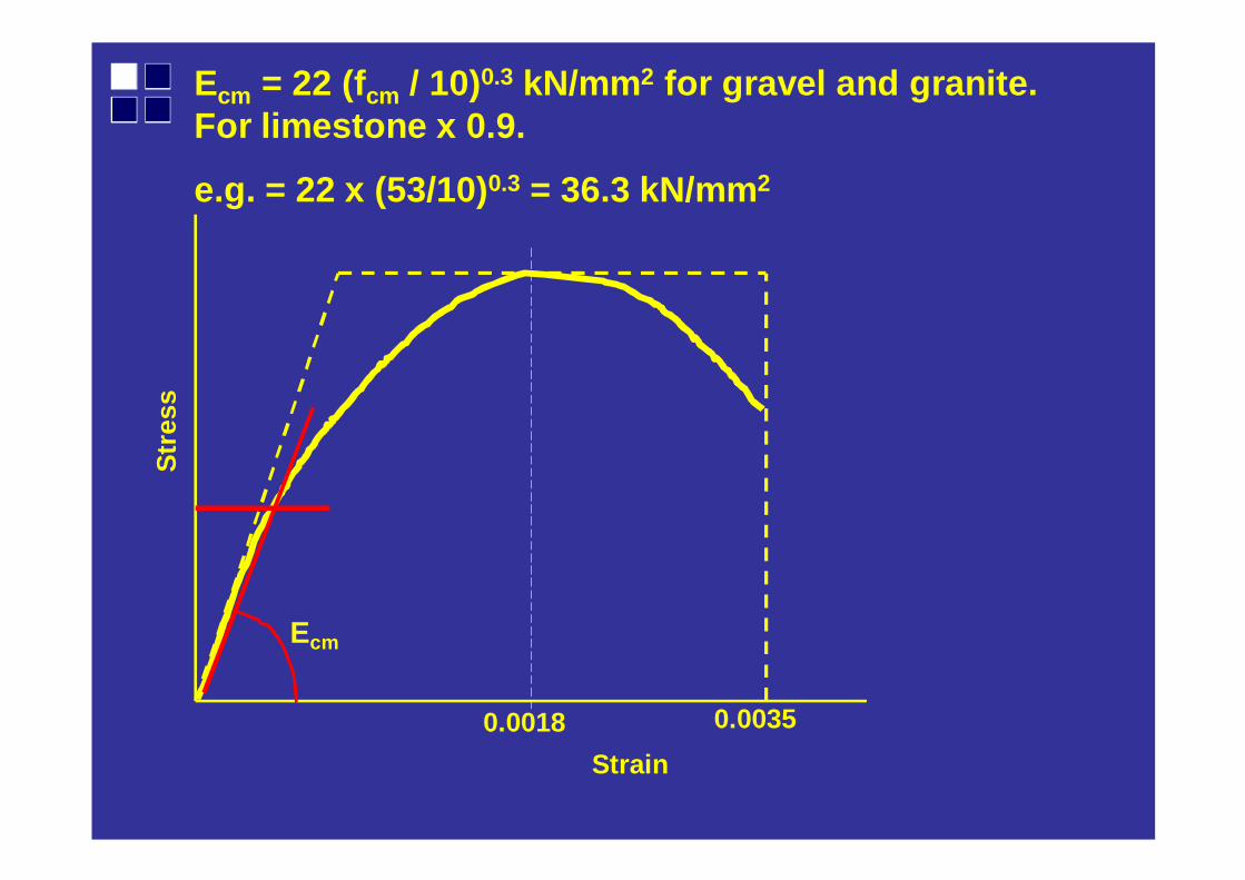
Ecm = 22 (fcm / 10)0.3 kN/mm 2 for gravel and granite. For limestone x 0.9.
e.g. = 22 x (53/10) 0.3 = 36.3 kN/mm 2S
tres
s
Strain
0.00350.0018
Ecm
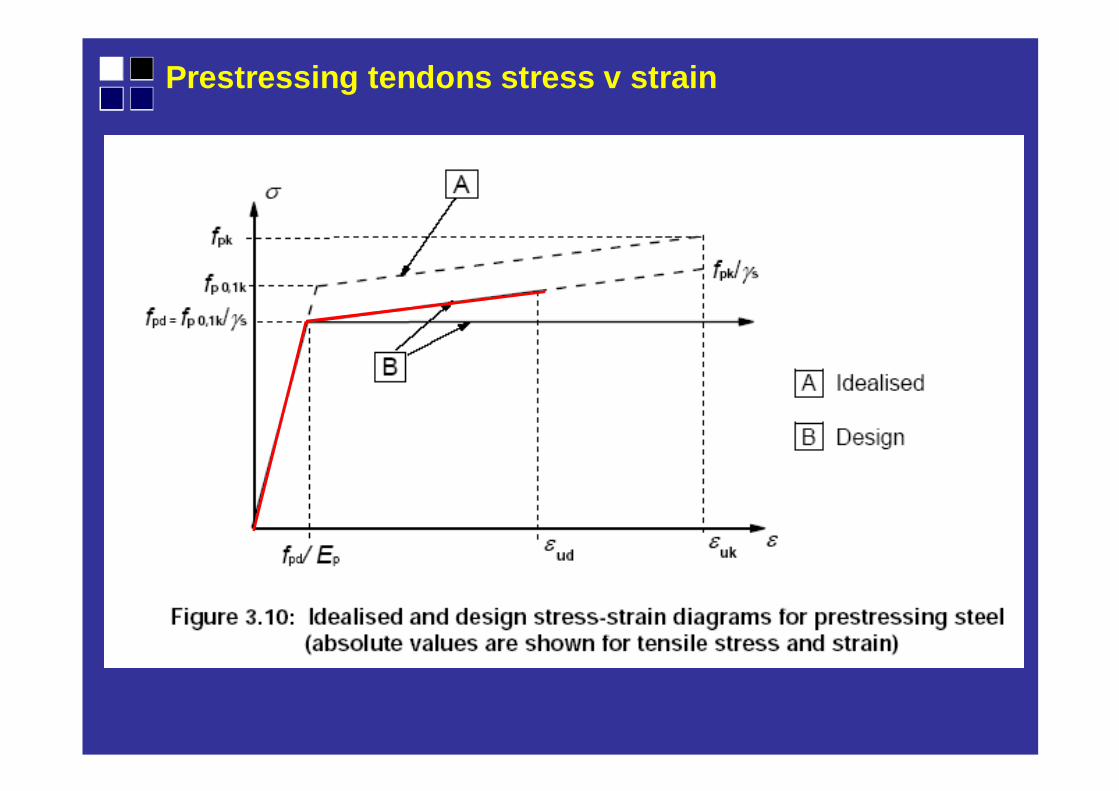
Prestressing tendons stress v strain
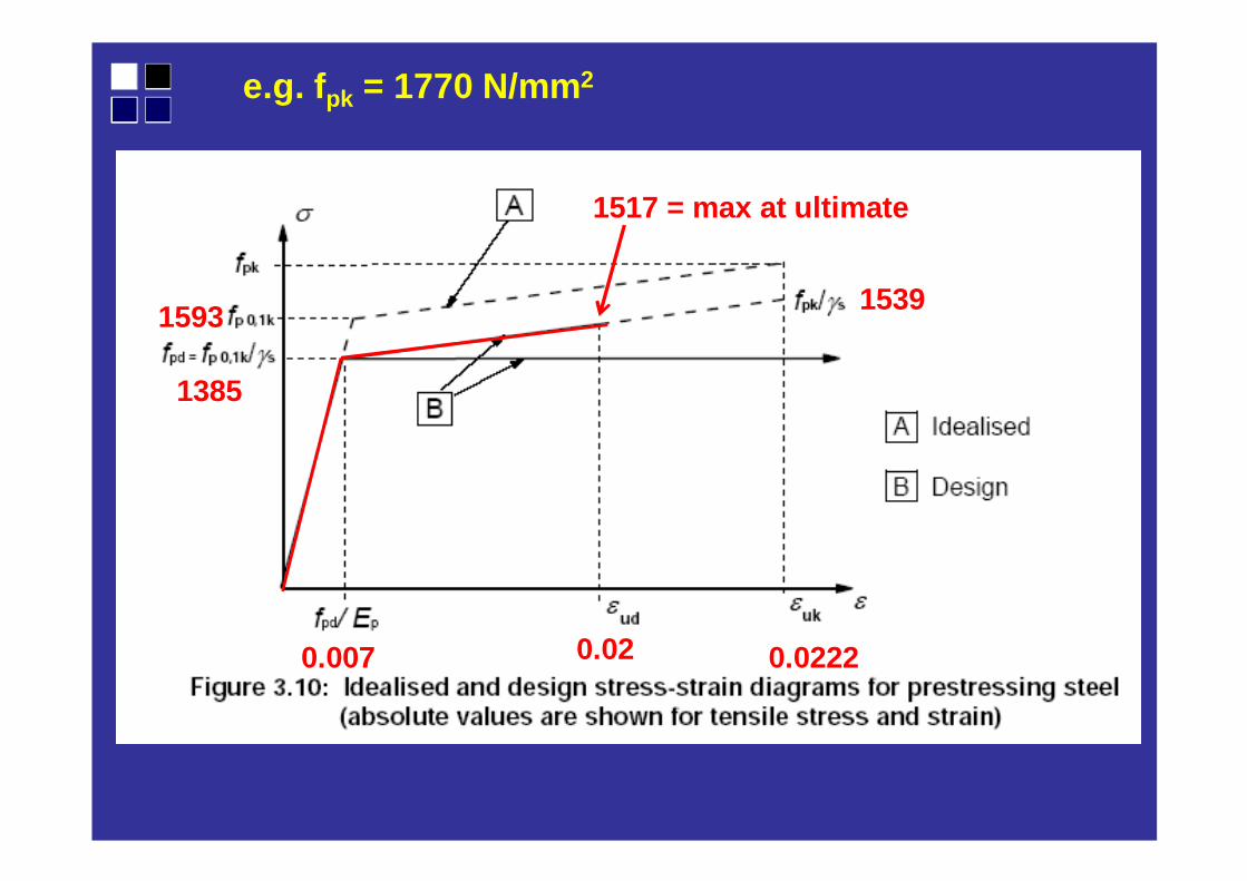
e.g. f pk = 1770 N/mm2
1539
0.02220.02
1517 = max at ultimate
0.007
1385
1593

Durability = nominal cover c = c min,dur + ∆∆∆∆cdev
For precast slabs > C30/37, use S2
Much better and recent information in BS 8500-1: 20 15

Construction deviation ∆∆∆∆cdev = 5 mm if tendon positions are controlled
Syllabus
Prestress.Losses.Limit f ctmMoment ofresistance.
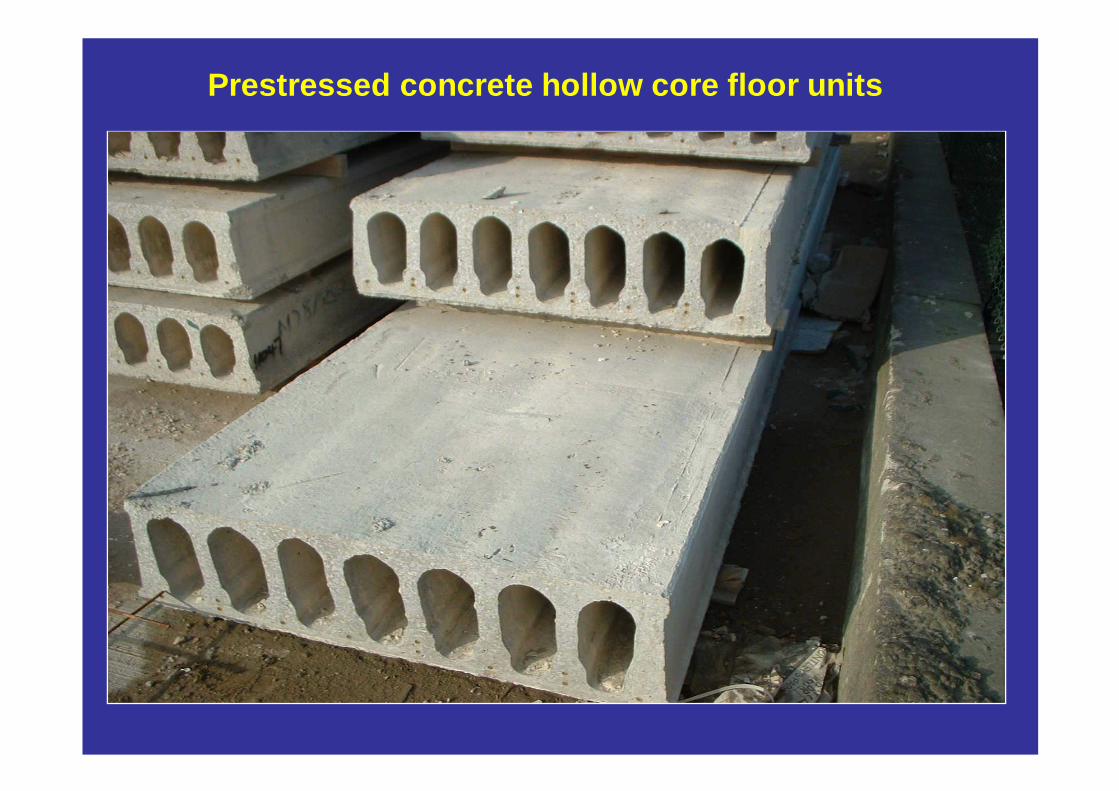
Prestressed concrete hollow core floor units
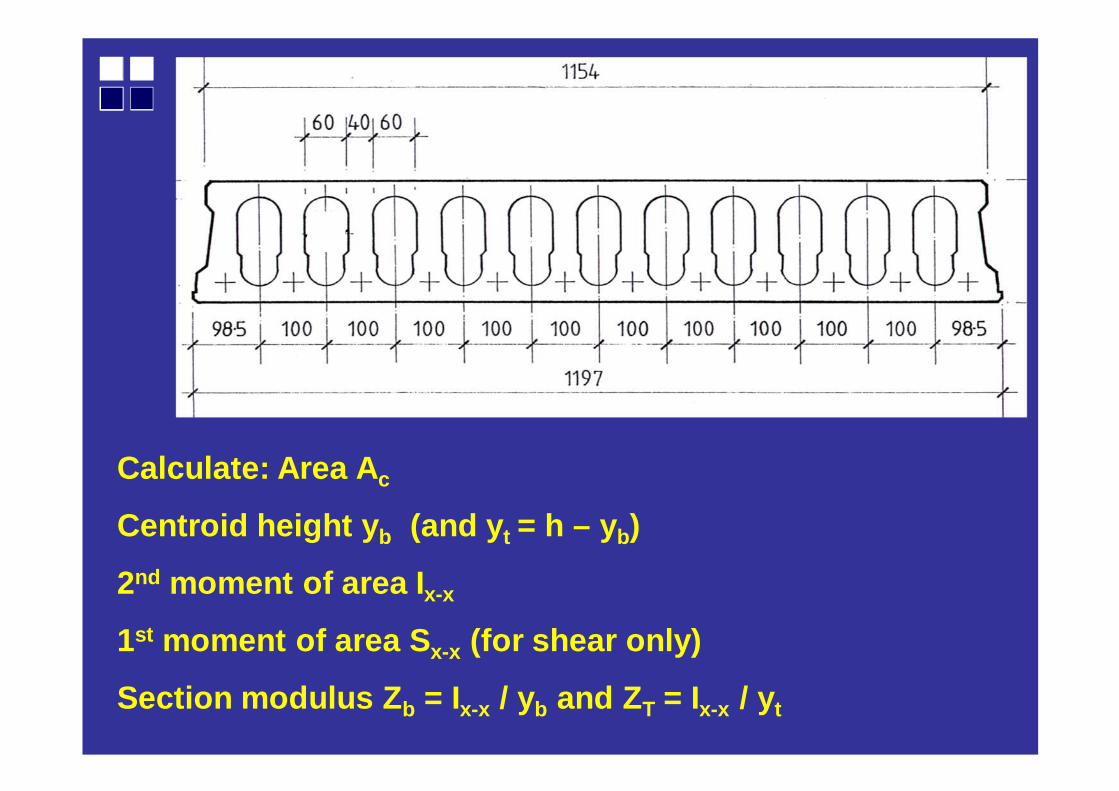
Calculate: Area A c
Centroid height y b (and y t = h – yb)
2nd moment of area I x-x
1st moment of area S x-x (for shear only)
Section modulus Z b = Ix-x / yb and Z T = Ix-x / yt
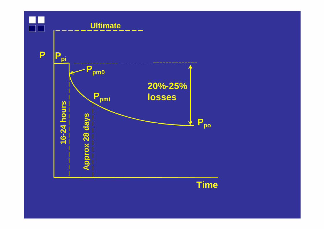
Ppm0
Ppi
Ppmi
Ppo
App
rox
28 d
ays
16-2
4 ho
urs
Time
P
Ultimate
20%-25% losses
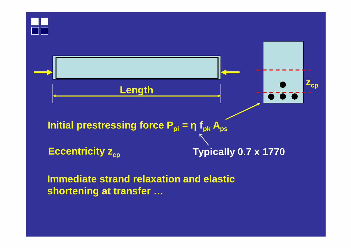
Initial prestressing force P pi = ηηηη fpk Aps
Length
Eccentricity z cp
zcp
Immediate strand relaxation and elastic shortening at transfer …
Typically 0.7 x 1770
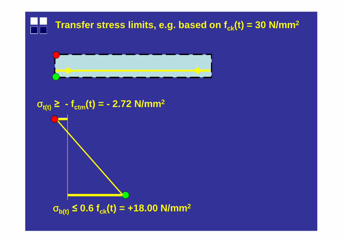
Transfer stress limits, e.g. based on f ck(t) = 30 N/mm 2
σσσσb(t) ≤ 0.6 fck(t) = +18.00 N/mm 2
σσσσt(t) ≥ - fctm (t) = - 2.72 N/mm 2
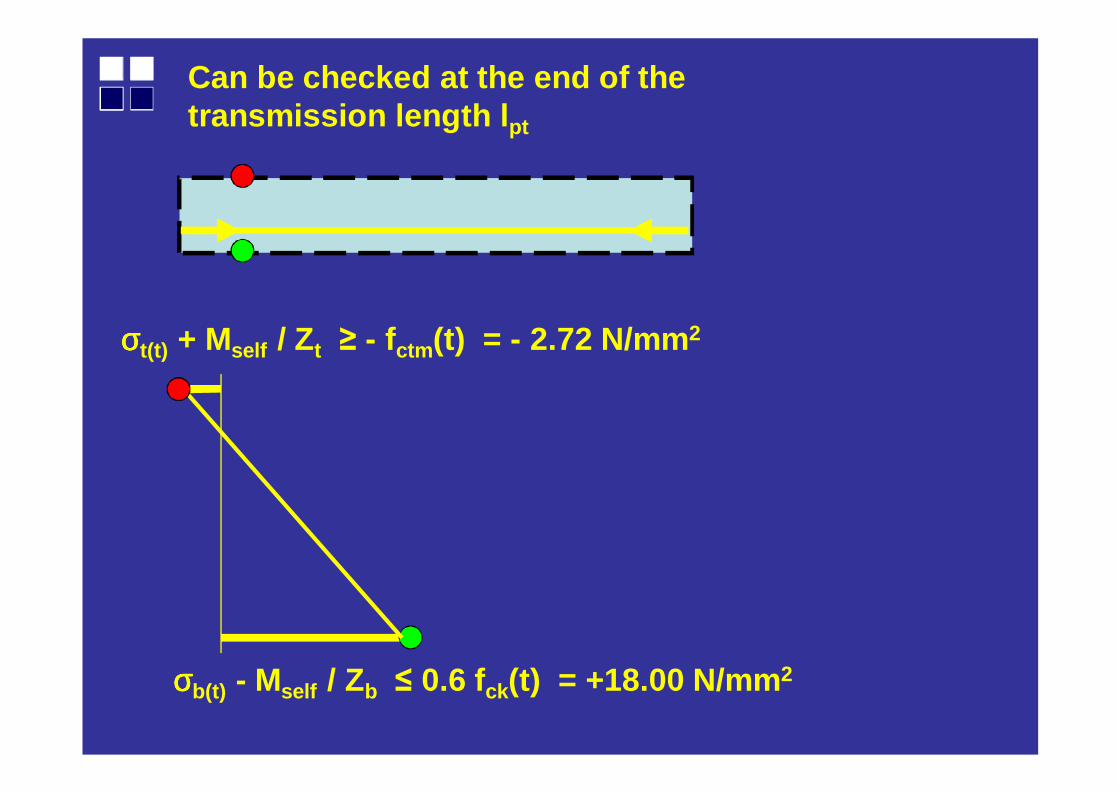
σσσσb(t) - Mself / Zb ≤ 0.6 fck(t) = +18.00 N/mm 2
σσσσt(t) + Mself / Zt ≥ - fctm (t) = - 2.72 N/mm 2
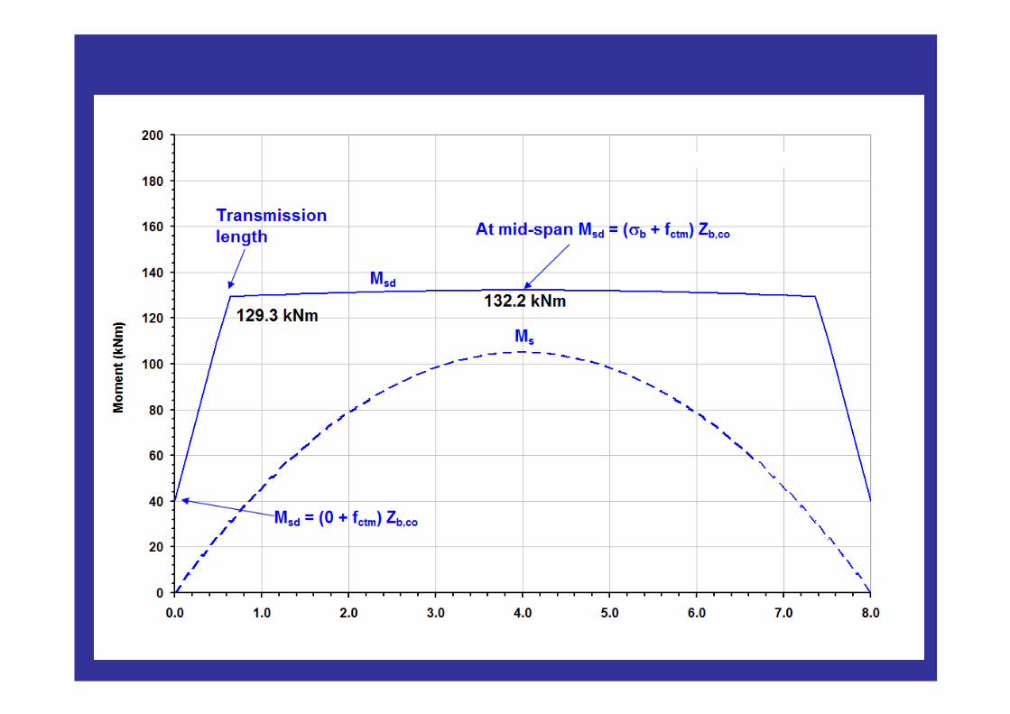
Can be checked at the end of the transmission length lpt
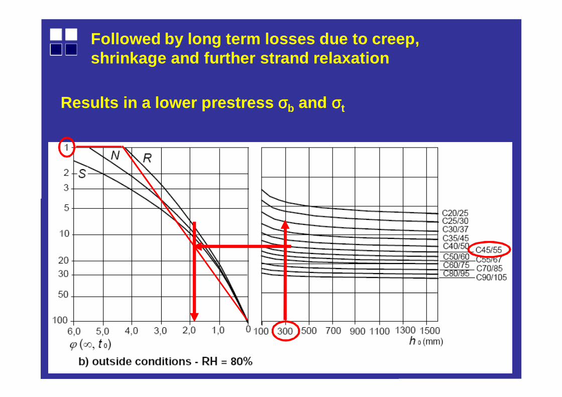
Followed by long term losses due to creep, shrinkage and further strand relaxation
Results in a lower prestress σσσσb and σσσσt
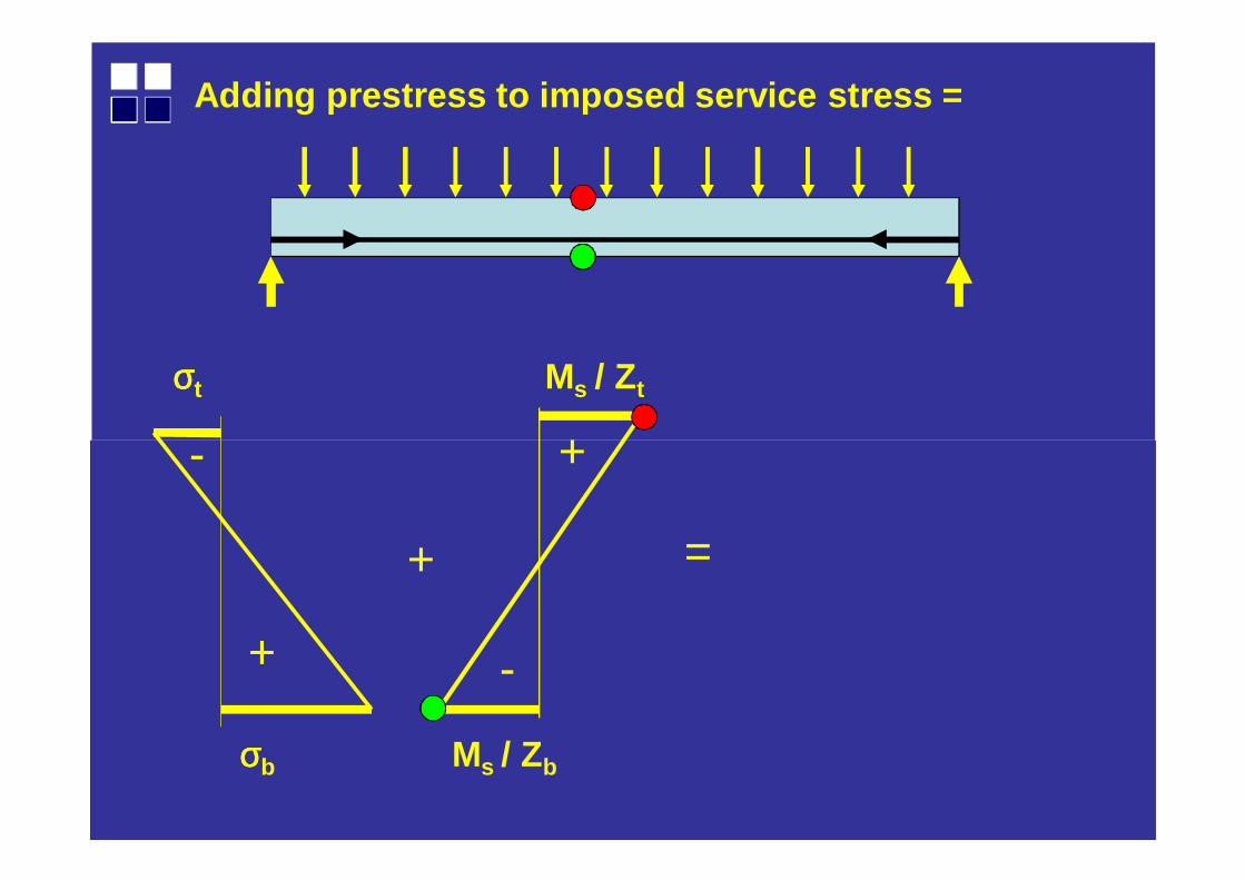
Adding prestress to imposed service stress =
+
+
-
σσσσt Ms / Zt
+
-
=
σσσσb Ms / Zb
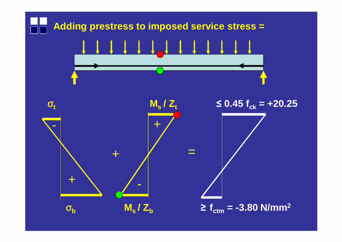
Adding prestress to imposed service stress =
+
+
-
σσσσt Ms / Zt ≤ 0.45 fck = +20.25
+
-
=
σσσσb Ms / Zb ≥ fctm = -3.80 N/mm2
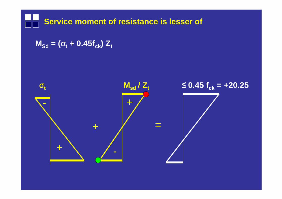
Service moment of resistance is lesser of
+
+
- +
-
=
MSd = (σσσσt + 0.45fck) Zt
σσσσt Msd / Zt ≤ 0.45 fck = +20.25
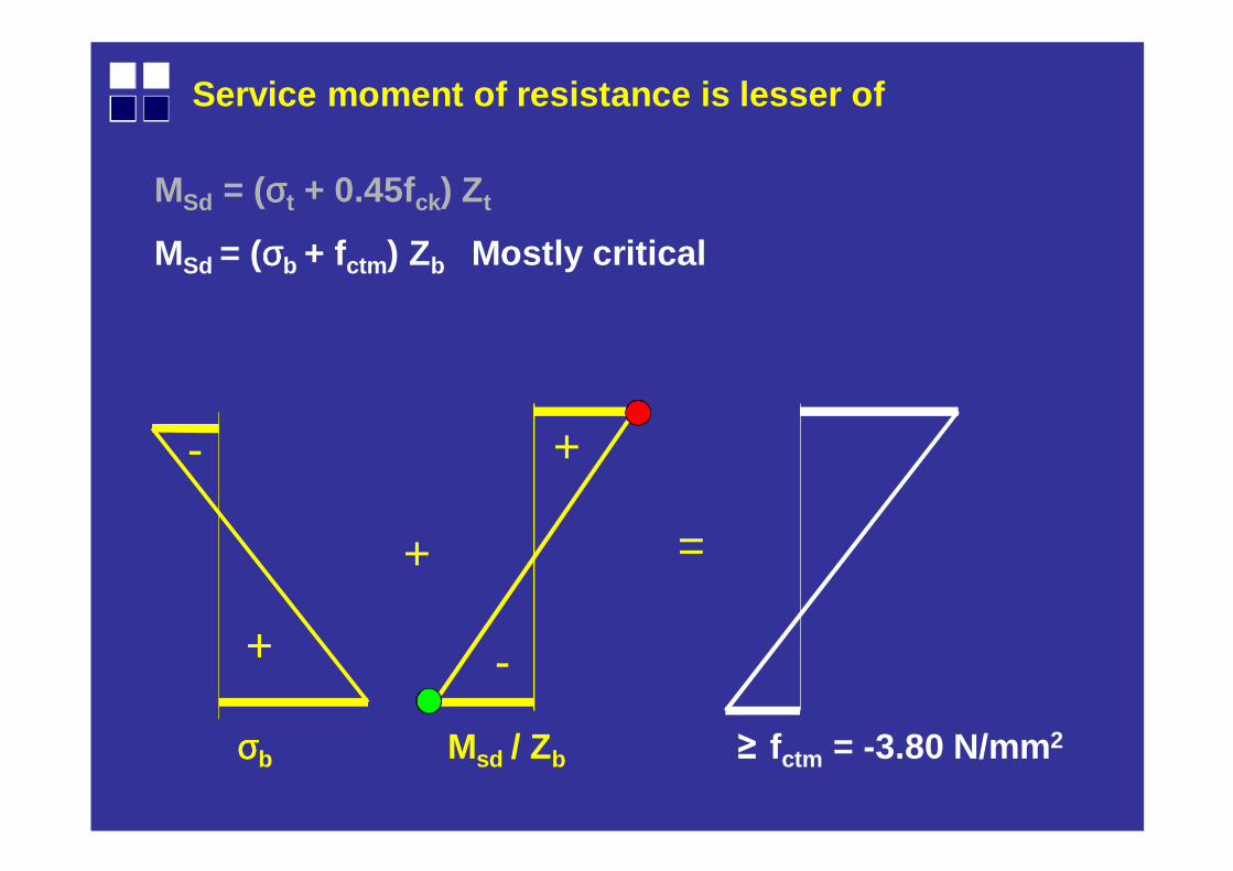
Service moment of resistance is lesser of
+
+
- +
-
=
MSd = (σσσσt + 0.45fck) Zt
MSd = (σσσσb + fctm ) Zb Mostly critical
σσσσb Msd / Zb ≥ fctm = -3.80 N/mm2
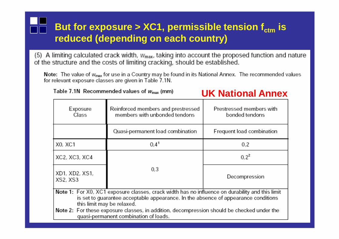
But for exposure > XC1, permissible tension f ctm is reduced (depending on each country)
UK National Annex
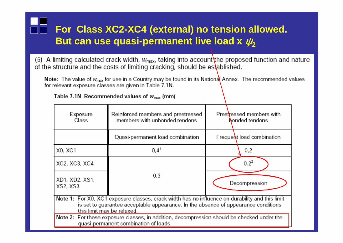
For Class XC2-XC4 (external) no tension allowed. But can use quasi-permanent live load x ψψψψ2
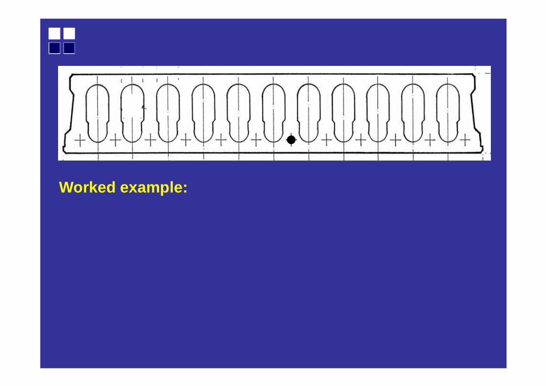
Worked example:
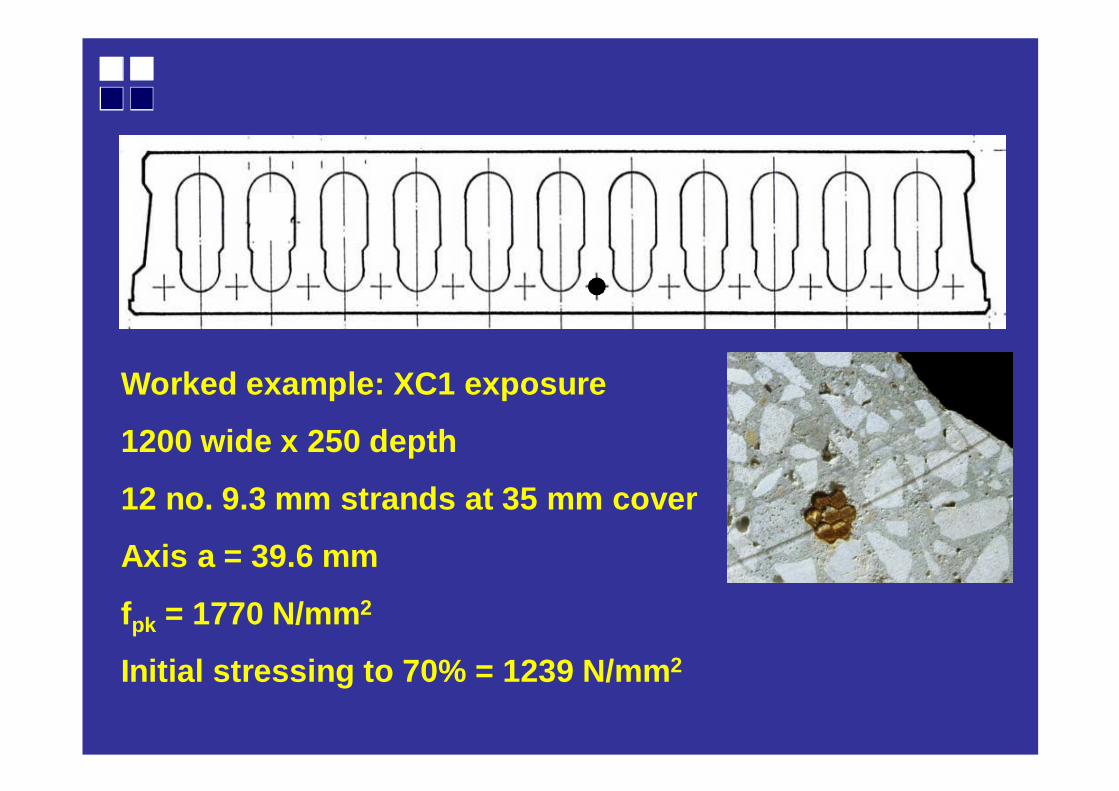
Worked example: XC1 exposure
1200 wide x 250 depth
12 no. 9.3 mm strands at 35 mm cover
Axis a = 39.6 mm
fpk = 1770 N/mm2
Initial stressing to 70% = 1239 N/mm 2
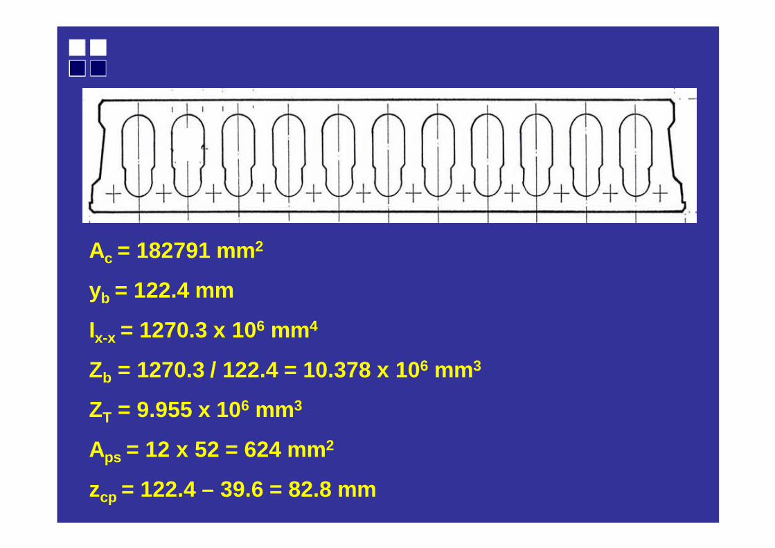
Ac = 182791 mm2
yb = 122.4 mm
Ix-x = 1270.3 x 106 mm4
Zb = 1270.3 / 122.4 = 10.378 x 106 mm3
ZT = 9.955 x 106 mm3
Aps = 12 x 52 = 624 mm 2
zcp = 122.4 – 39.6 = 82.8 mm
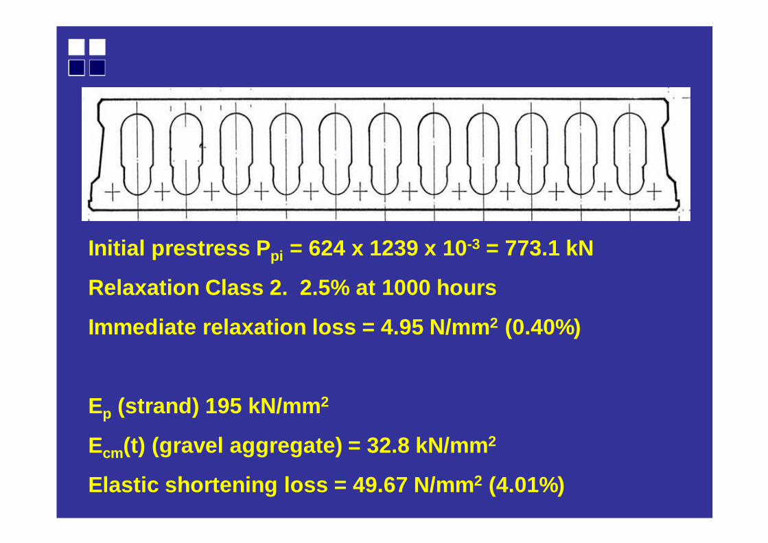
Initial prestress P pi = 624 x 1239 x 10 -3 = 773.1 kN
Relaxation Class 2. 2.5% at 1000 hours
Immediate relaxation loss = 4.95 N/mm 2 (0.40%)
Ep (strand) 195 kN/mm 2
Ecm(t) (gravel aggregate) = 32.8 kN/mm 2
Elastic shortening loss = 49.67 N/mm 2 (4.01%)
zcp
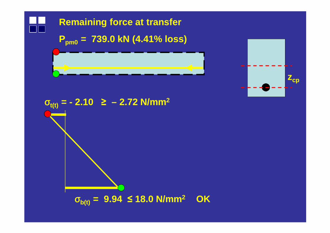
Remaining force at transfer
Ppm0 = 739.0 kN (4.41% loss)
σσσσb(t) = 9.94 ≤ 18.0 N/mm2 OK
σσσσt(t) = - 2.10 ≥ – 2.72 N/mm2
Further loss of prestress at installation at (say) 28 days:
RH at transfer = 70%
Creep coefficient at 28 days = 0.84
Creep loss of stress at 28 days = 34.0 N/mm 2 (2.74%)
Ppmi = 717.8 kN (this is used later to determine camber after installation)
Final loss of prestress at 500,000 hours (57 years) :
RH at service (indoor exposure) = 50%
Creep coefficient from installation to life = 1.60
Creep loss of stress = 61.8 N/mm 2 (4.99%)
Shrinkage εεεεsh = 420 x 10-6
Shrinkage loss = 74.7 N/mm 2 (6.03%)
Long term relaxation loss = 40.3 N/mm 2 (3.25%)

zcp
After all losses
Pp0 = 614.3 kN (20.5% loss)
σσσσb = 8.26 N/mm2
σσσσt = - 1.746 N/mm2
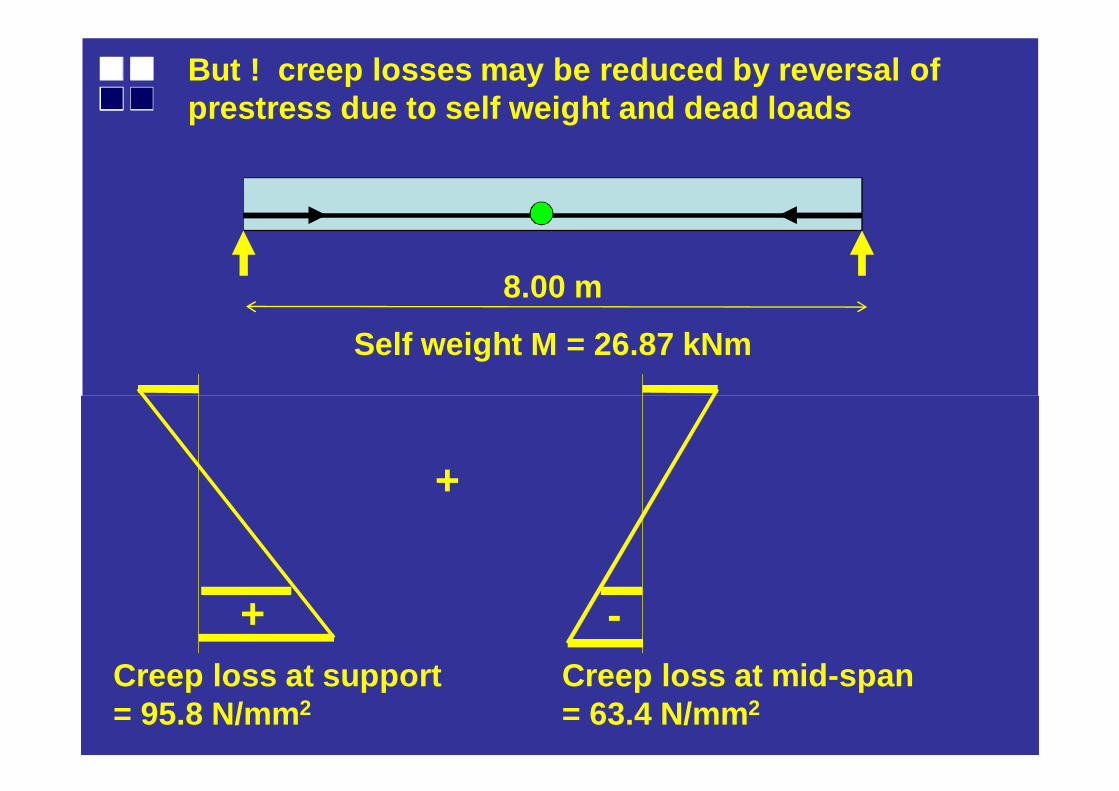
But ! creep losses may be reduced by reversal of prestress due to self weight and dead loads
Creep loss at support = 95.8 N/mm2
8.00 m
Self weight M = 26.87 kNm
Creep loss at mid-span = 63.4 N/mm2
+
+ -
+
-
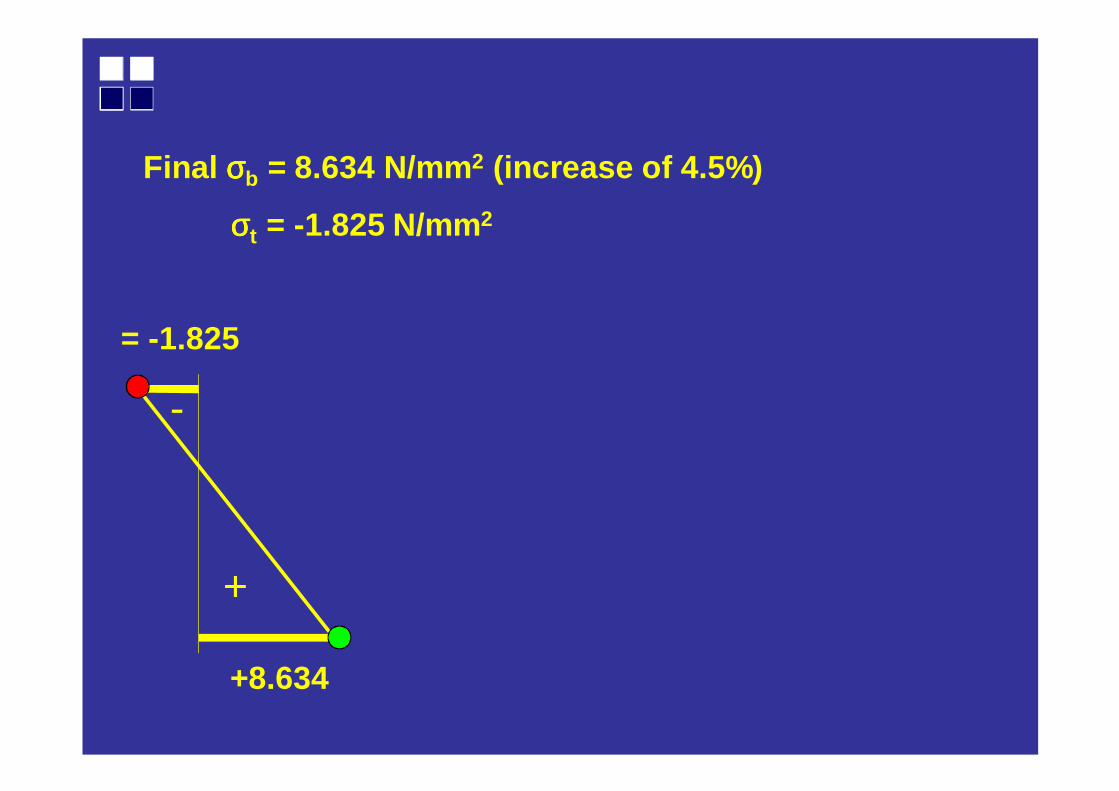
= -1.825
+8.634
Final σσσσb = 8.634 N/mm2 (increase of 4.5%)
σσσσt = -1.825 N/mm2
+
+
-
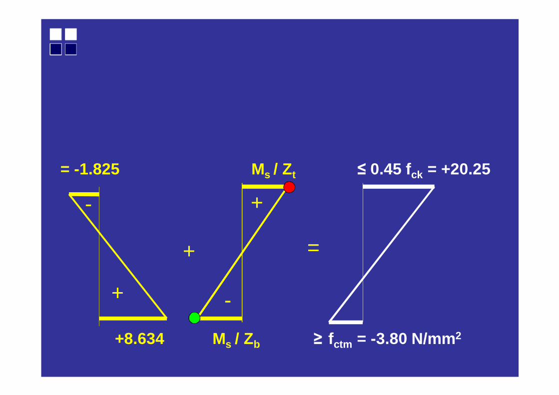
= -1.825 Ms / Zt ≤ 0.45 fck = +20.25
+
-
=
+8.634 Ms / Zb ≥ fctm = -3.80 N/mm2
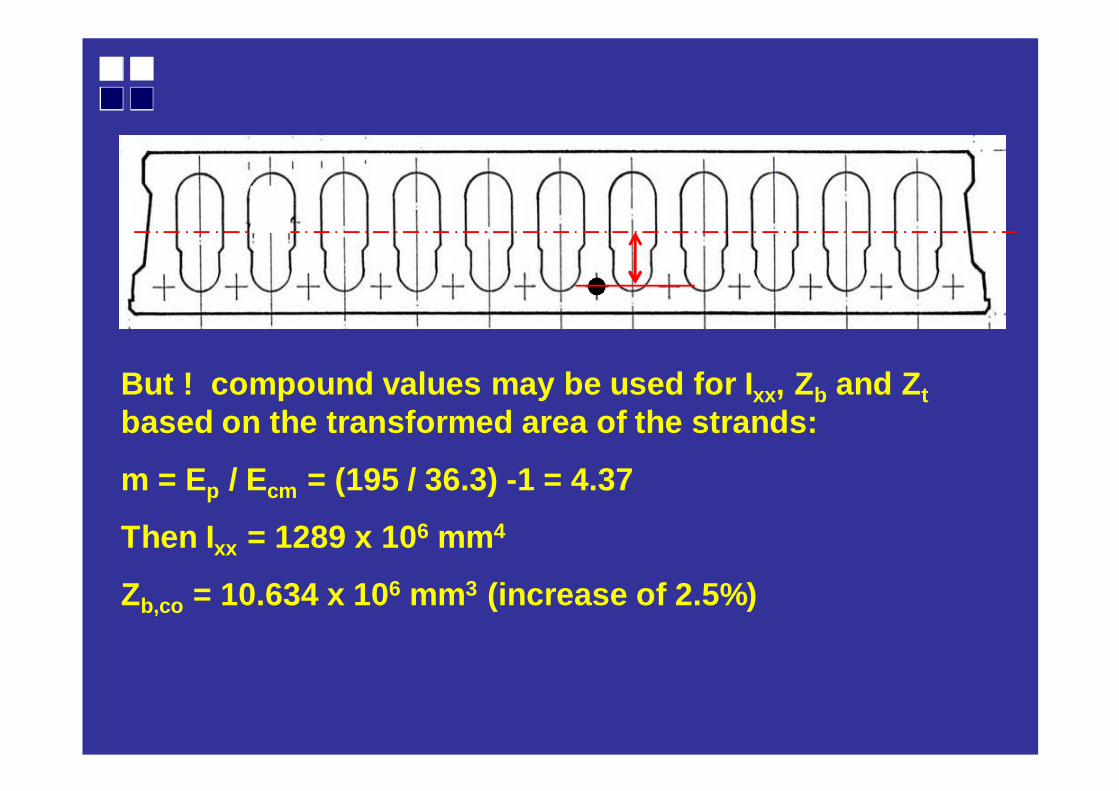
But ! compound values may be used for I xx, Zb and Z tbased on the transformed area of the strands:
m = Ep / Ecm = (195 / 36.3) -1 = 4.37
Then Ixx = 1289 x 106 mm4
Zb,co = 10.634 x 106 mm3 (increase of 2.5%)
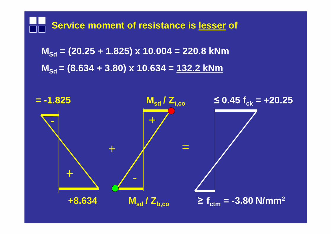
Service moment of resistance is lesser of
+
+
- +
-
=
MSd = (20.25 + 1.825) x 10.004 = 220.8 kNm
MSd = (8.634 + 3.80) x 10.634 = 132.2 kNm
+8.634 Msd / Zb,co ≥ fctm = -3.80 N/mm2
= -1.825 Msd / Zt,co ≤ 0.45 fck = +20.25

Syllabus
Ultimate strength.Equilibrium.Compatibility.MRd.

4 point bending test of prestressed hollow core sla b.
Initial camber = -27 mm
1200 x 320 deep x 11.0 m span
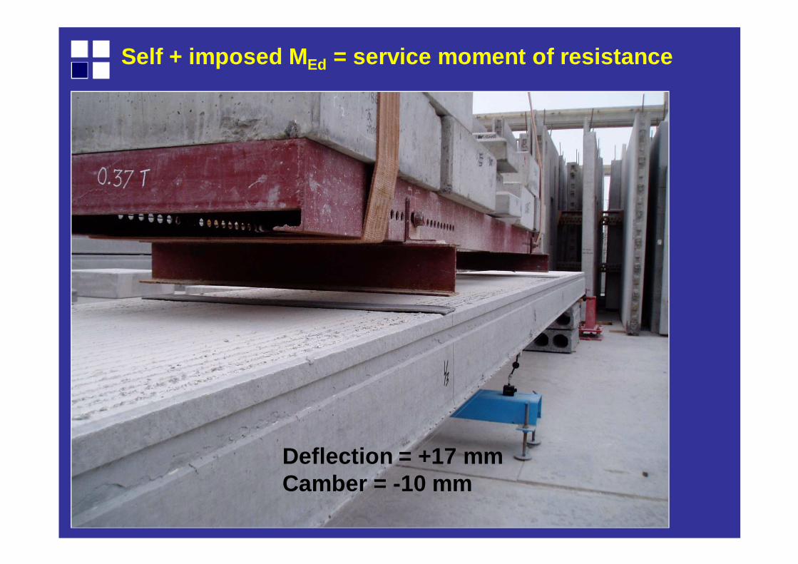
Self + imposed M Ed = service moment of resistance
Deflection = +17 mm Camber = -10 mm
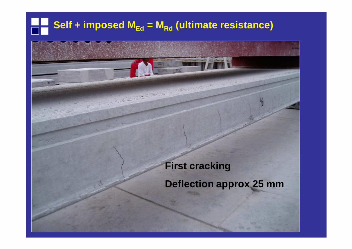
Self + imposed M Ed = MRd (ultimate resistance)
First cracking
Deflection approx 25 mm
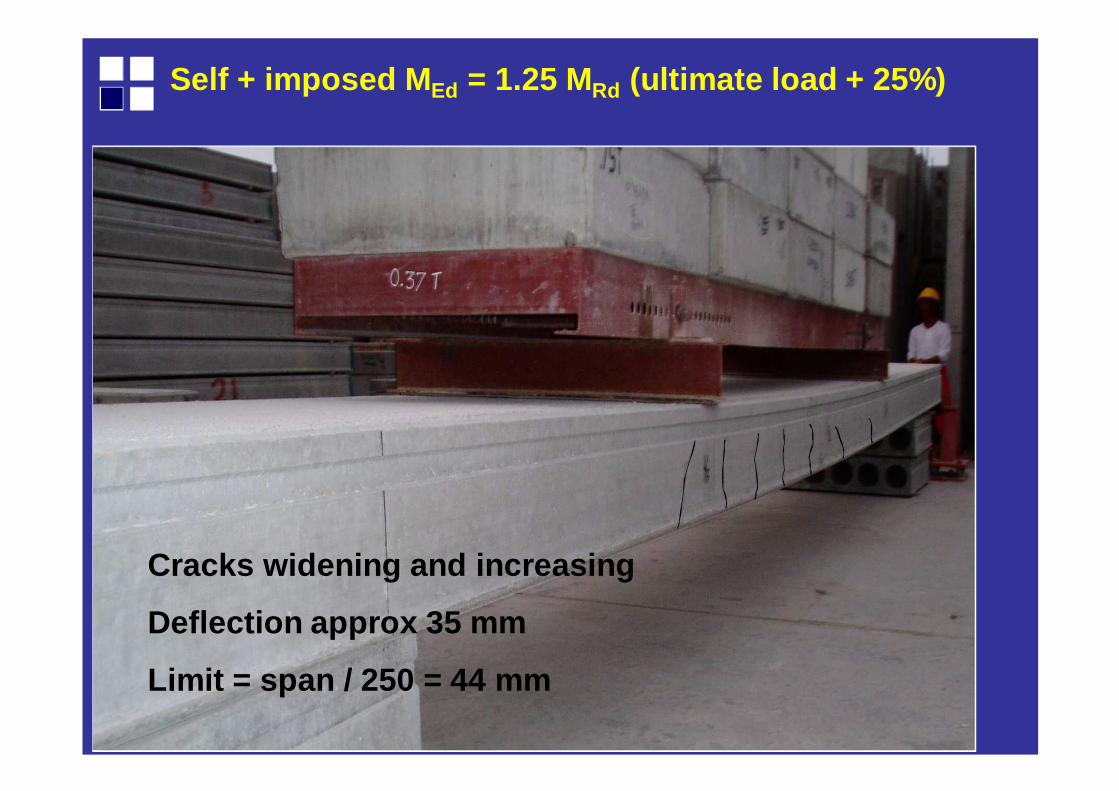
Self + imposed M Ed = 1.25 MRd (ultimate load + 25%)
Cracks widening and increasing
Deflection approx 35 mm
Limit = span / 250 = 44 mm
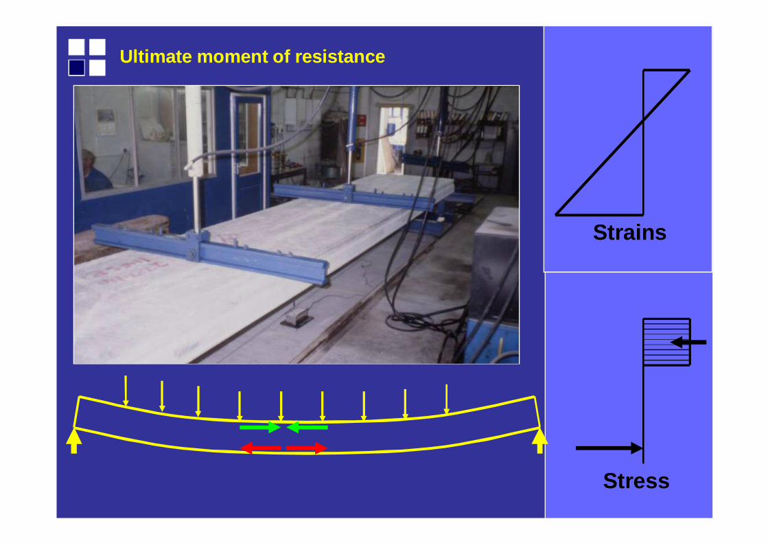
Ultimate moment of resistance
Strains
Stress
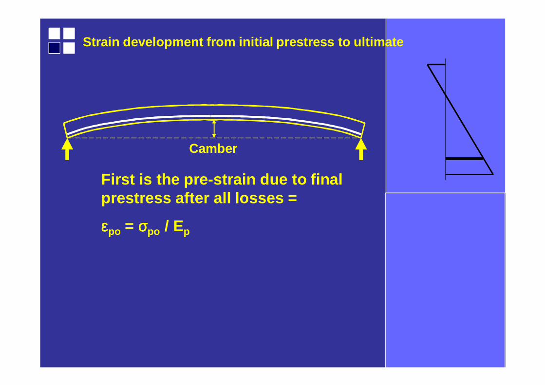
Strain development from initial prestress to ultima te
Camber
First is the pre-strain due to final prestress after all losses =
εεεεpo = σσσσpo / Ep
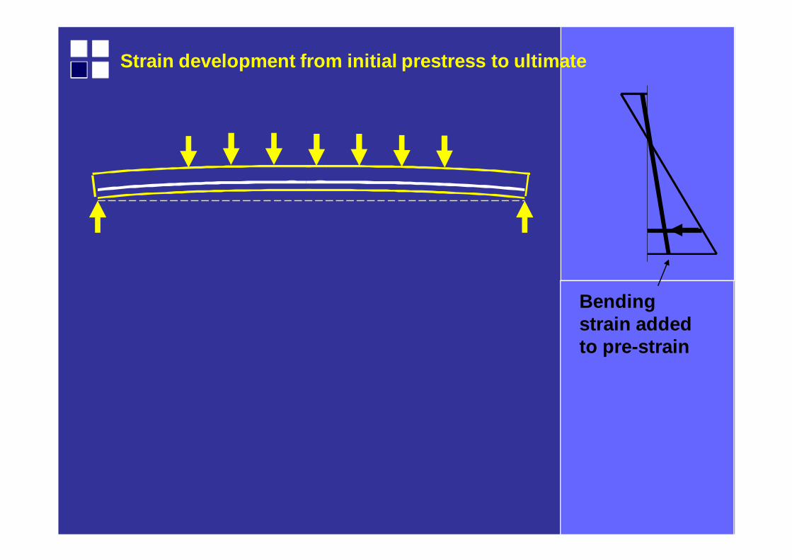
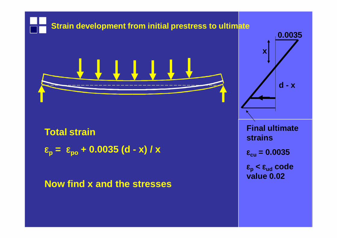
Strain development from initial prestress to ultima te
Bending strain added to pre-strain
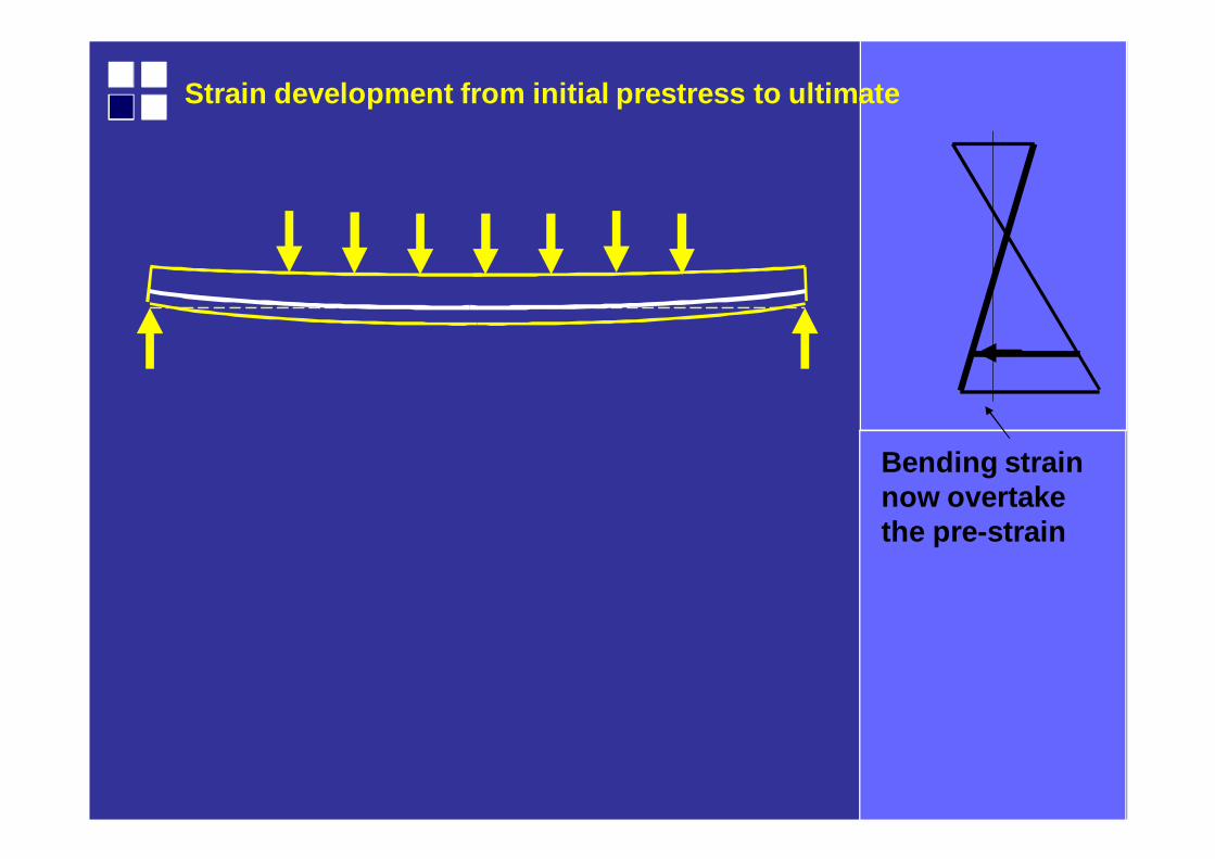
Strain development from initial prestress to ultima te
Bending strain now overtake the pre-strain
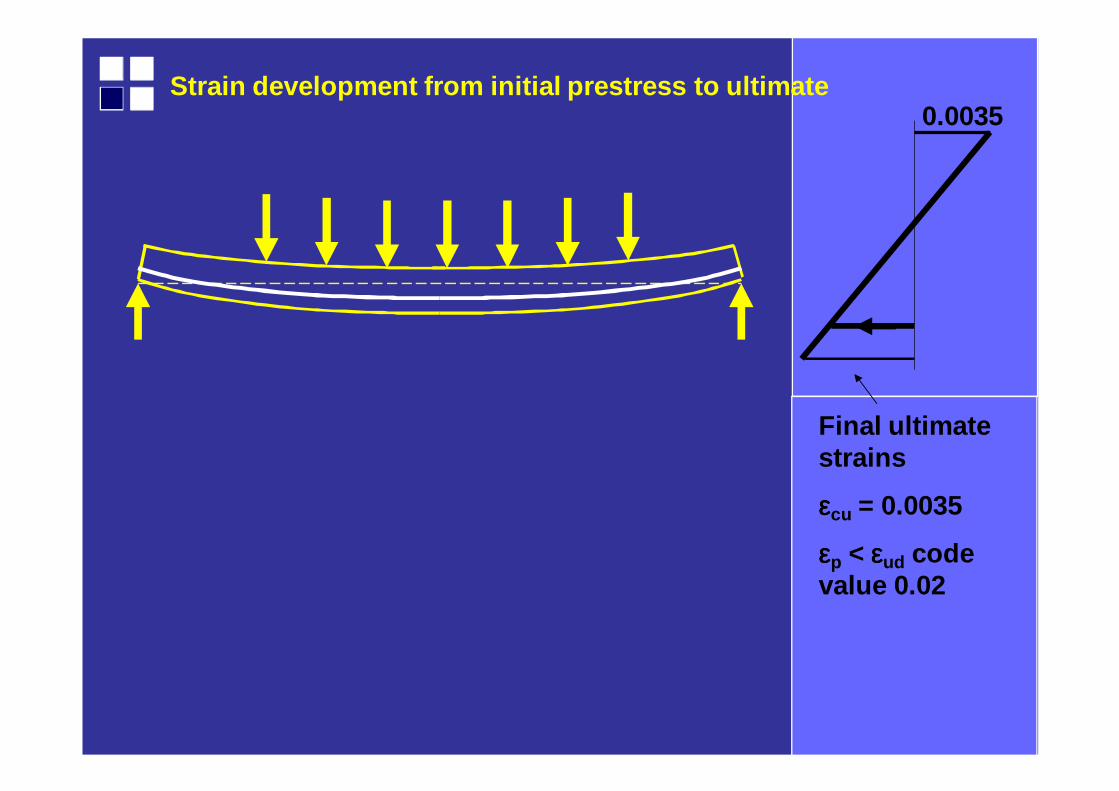
Strain development from initial prestress to ultima te
Final ultimate strains
εεεεcu = 0.0035
εεεεp < εεεεud code value 0.02
0.0035
Strain development from initial prestress to ultima te0.0035
Total strain
εεεεp = εεεεpo + 0.0035 (d - x) / x
Now find x and the stresses
x
d - x
Final ultimate strains
εεεεcu = 0.0035
εεεεp < εεεεud code value 0.02
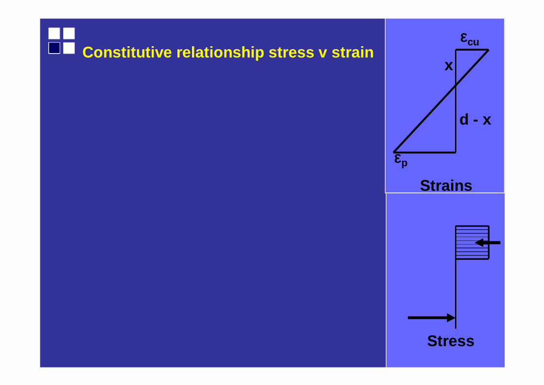
Strains
Stress
Constitutive relationship stress v strain
εεεεp
εεεεcu
x
d - x
Strains
Stress
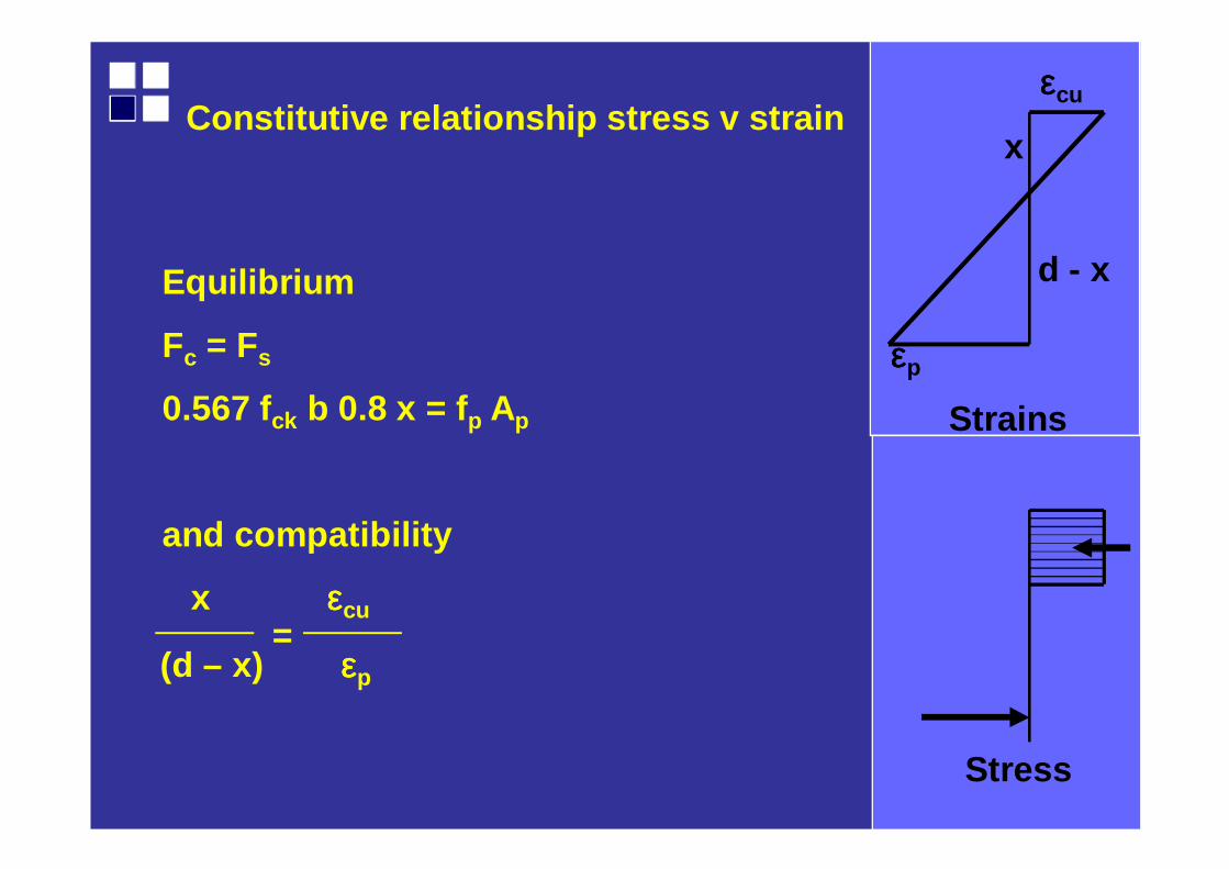
Constitutive relationship stress v strain
εεεεp
εεεεcu
x
d - xEquilibrium
Fc = Fs
0.567 fck b 0.8 x = f p Ap
and compatibility
x εεεεcu
(d – x) εεεεp
=
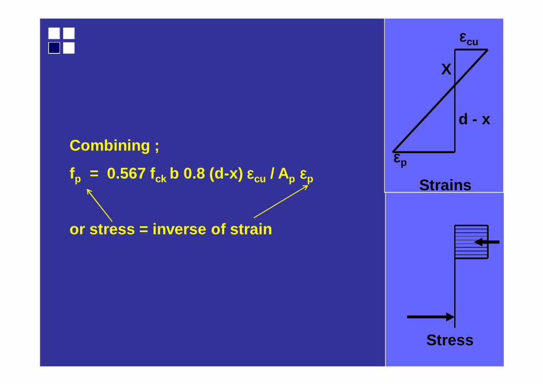
Strains
Stress
εεεεp
εεεεcu
X
d - x
Combining ;
fp = 0.567 fck b 0.8 (d-x) εεεεcu / Ap εεεεp
or stress = inverse of strain
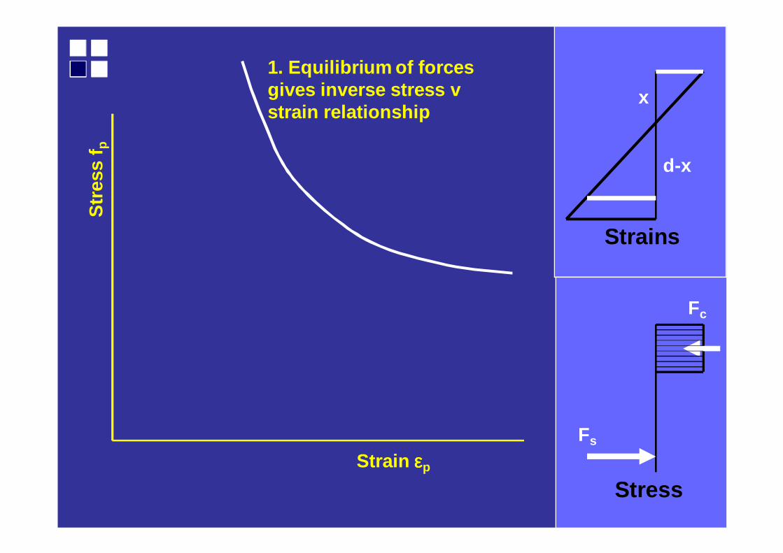
Strains
Stress
1. Equilibrium of forces gives inverse stress v strain relationship
Str
ess
f p
Strain εεεεp
Fs
Fc
x
d-x
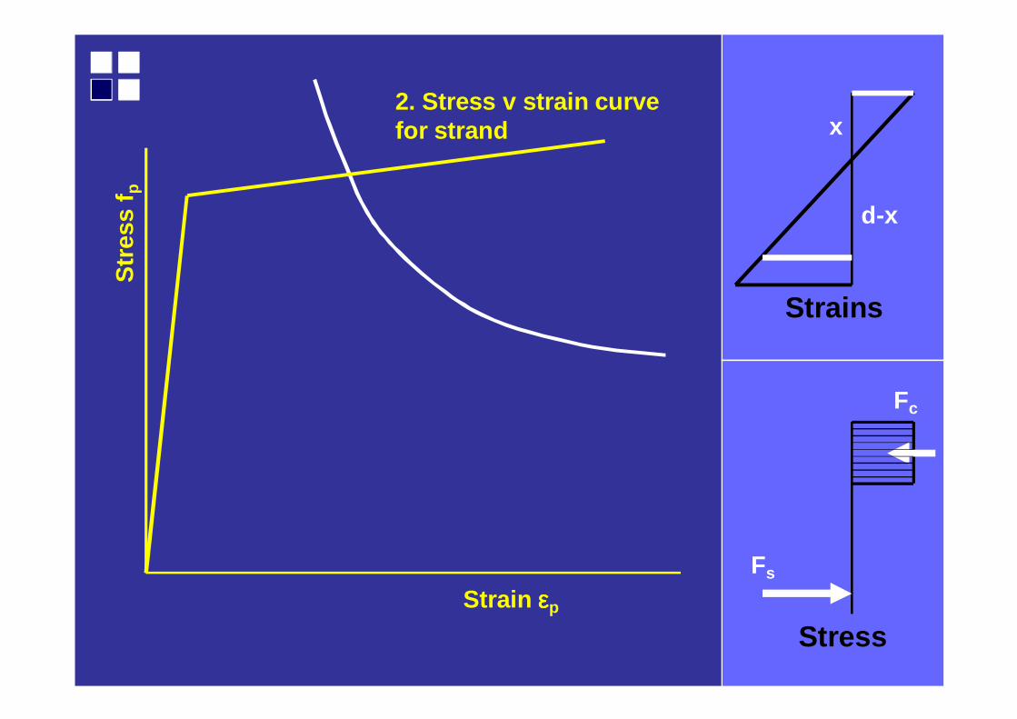
Strains
Stress
2. Stress v strain curve for strand
Str
ess
f p
Strain εεεεp
Fs
Fc
x
d-x
Strain
Str
ess
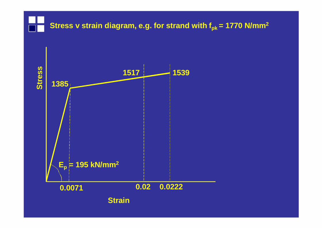
0.02220.02
153915171385
Ep = 195 kN/mm 2
0.0071
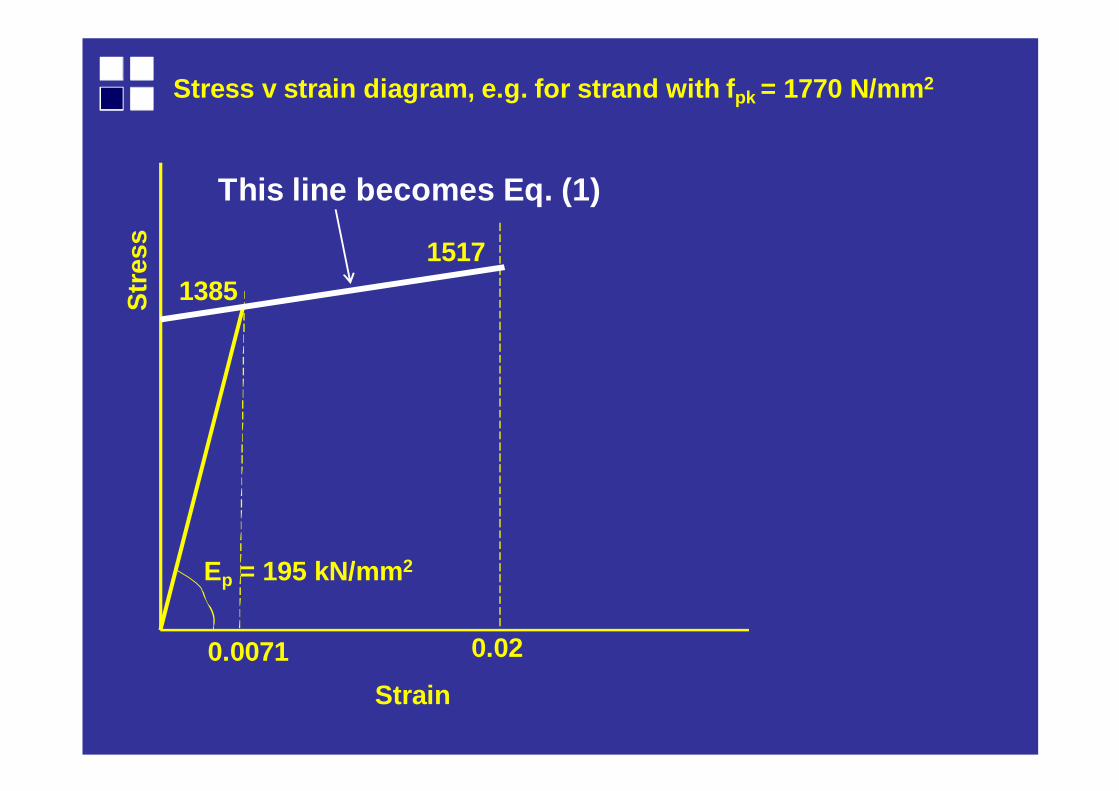
Stress v strain diagram, e.g. for strand with f pk = 1770 N/mm2
Str
ess
0.02
15171385
Ep = 195 kN/mm 2
0.0071
This line becomes Eq. (1)
Stress v strain diagram, e.g. for strand with f pk = 1770 N/mm2
Strain
Strains
Stress
Fs
Fc
x
d-x
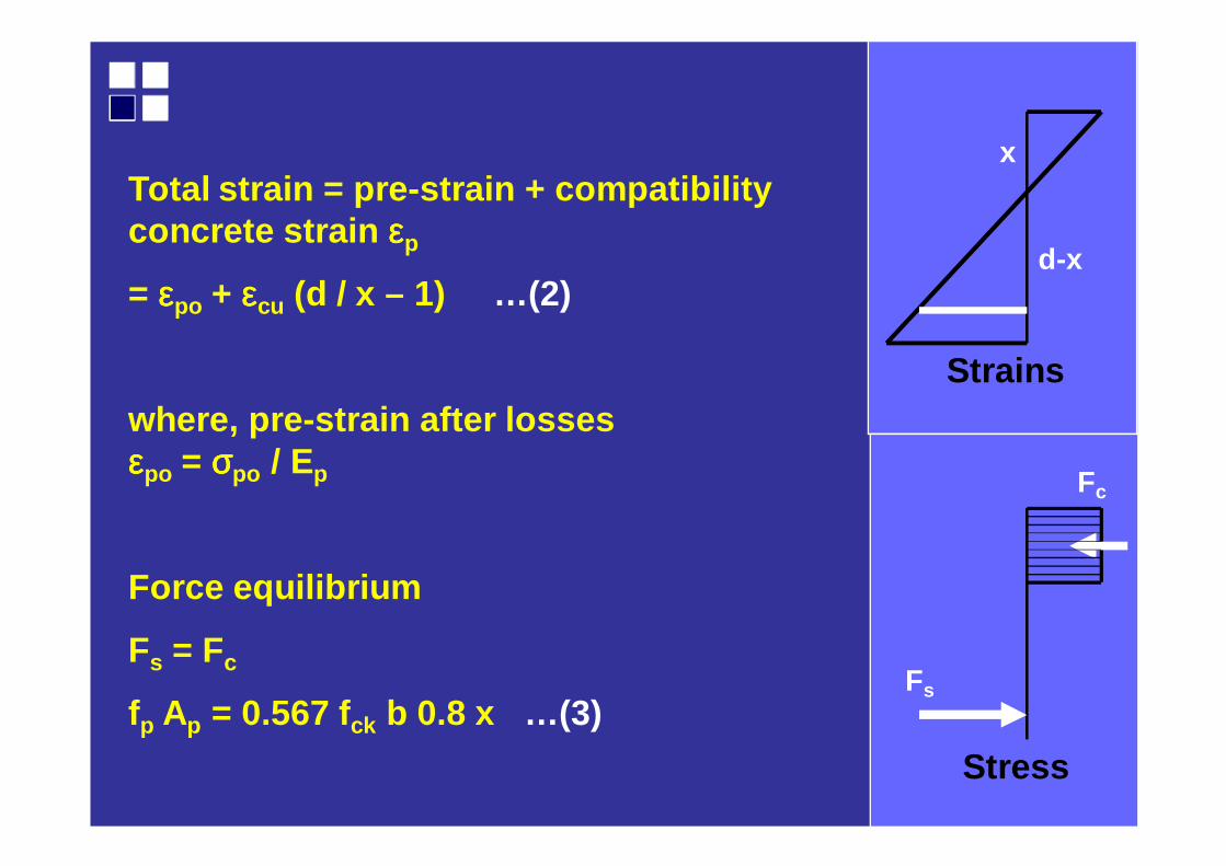
Total strain = pre-strain + compatibility concrete strain εεεεp
= εεεεpo + εεεεcu (d / x – 1) …(2)
where, pre-strain after losses εεεεpo = σσσσpo / Ep
Force equilibrium
Fs = Fc
fp Ap = 0.567 fck b 0.8 x …(3)
Strains
Stress
Fs
Fc
x
d-x
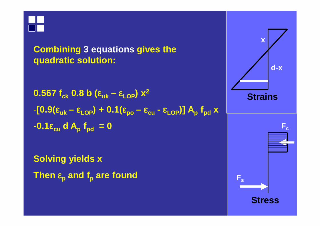
Combining 3 equations gives the quadratic solution:
0.567 fck 0.8 b (εεεεuk – εεεεLOP) x2
-[0.9(εεεεuk – εεεεLOP) + 0.1(εεεεpo – εεεεcu - εεεεLOP)] Ap fpd x
-0.1εεεεcu d Ap fpd = 0
Solving yields x
Then εεεεp and f p are found
Strains
Stress
Fs
Fc
X
d-x
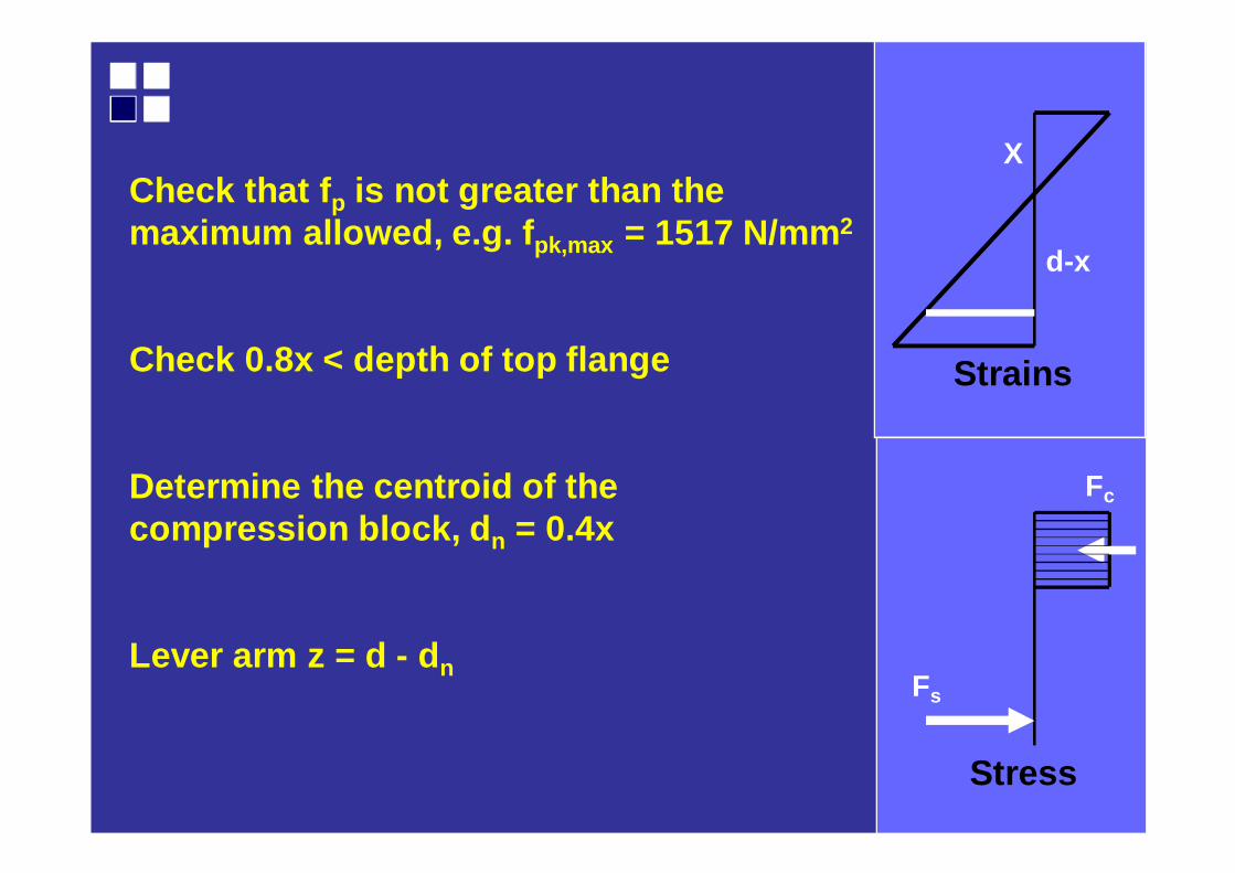
Check that f p is not greater than the maximum allowed, e.g. f pk,max = 1517 N/mm2
Check 0.8x < depth of top flange
Determine the centroid of the compression block, d n = 0.4x
Lever arm z = d - d n
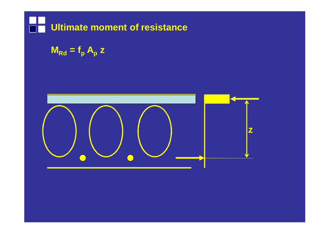
Ultimate moment of resistance
MRd = fp Ap z
z
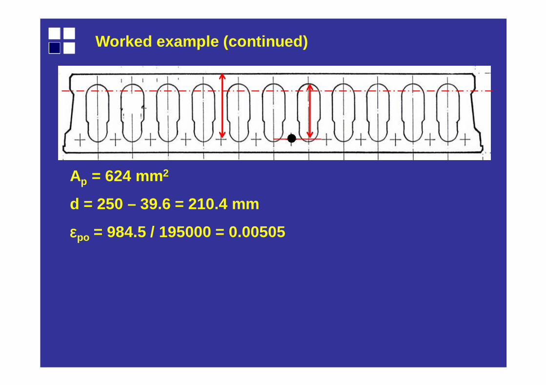
Ap = 624 mm2
d = 250 – 39.6 = 210.4 mm
εεεεpo = 984.5 / 195000 = 0.00505
Worked example (continued)
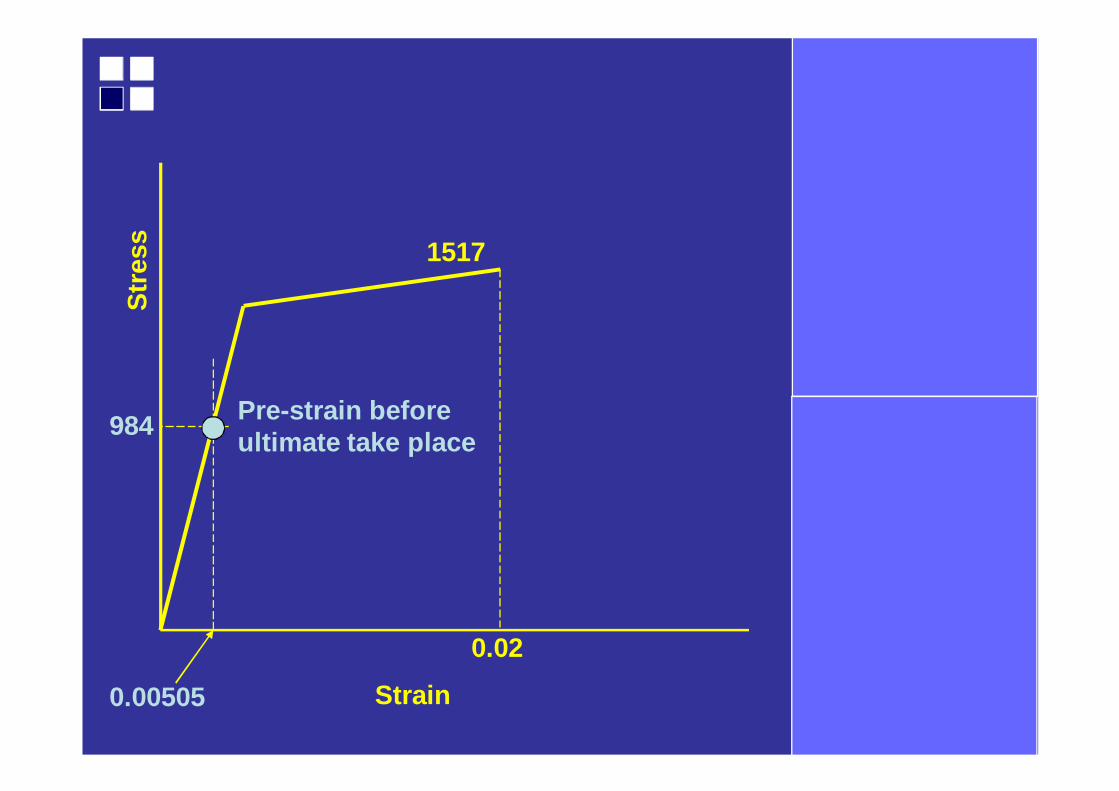
Str
ess
0.02
1517
0.00505
984 Pre-strain before ultimate take place
Strain
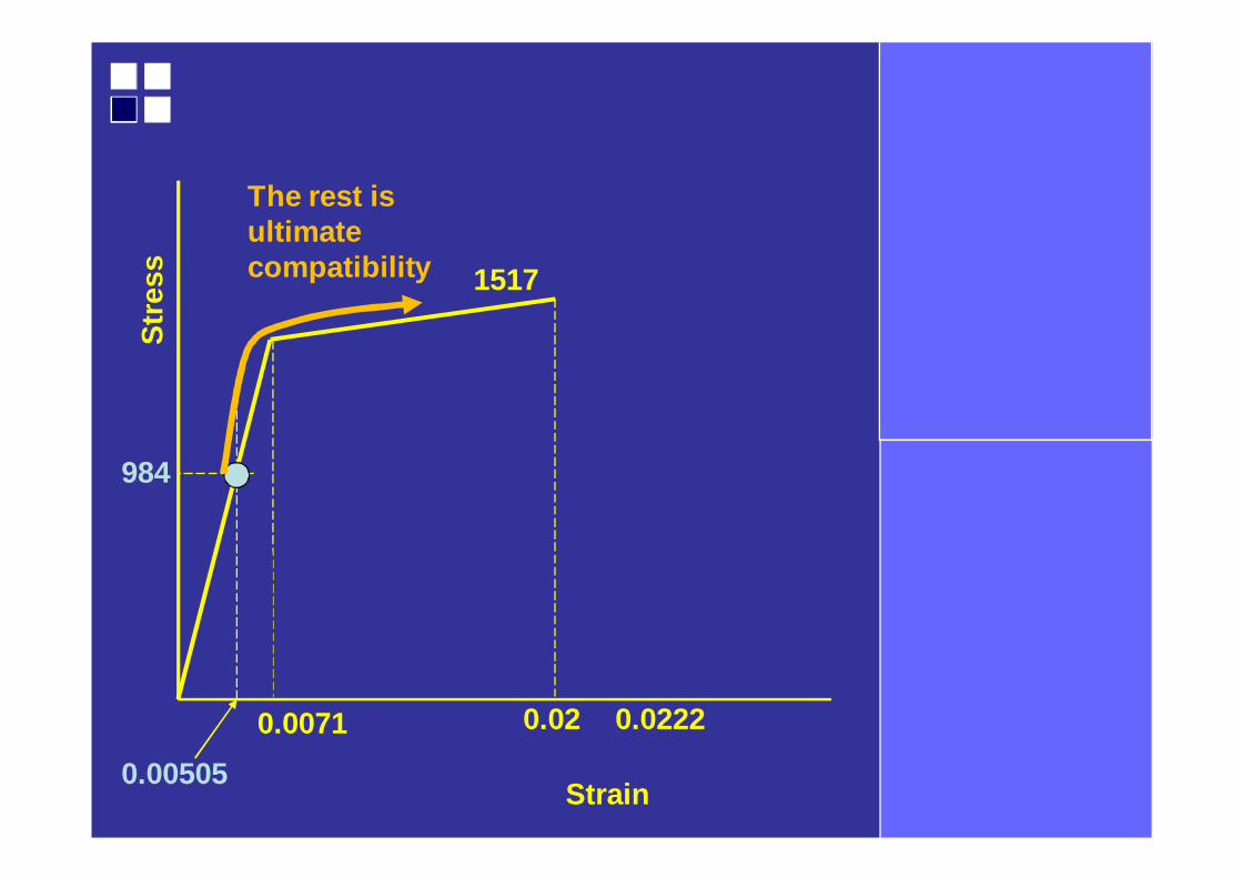
Strain
Str
ess
0.02220.02
1517
0.0071
0.00505
984
The rest is ultimate compatibility
Worked example
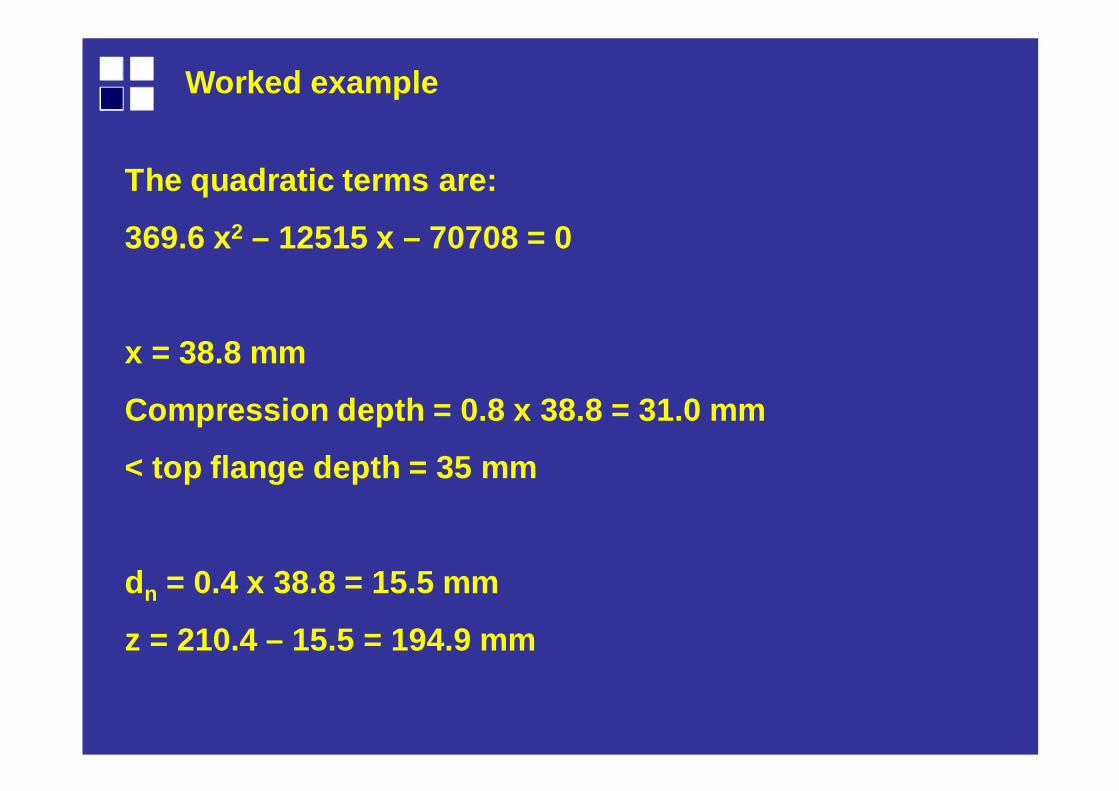
The quadratic terms are:
369.6 x2 – 12515 x – 70708 = 0
x = 38.8 mm
Compression depth = 0.8 x 38.8 = 31.0 mm
< top flange depth = 35 mm
dn = 0.4 x 38.8 = 15.5 mm
z = 210.4 – 15.5 = 194.9 mm
Worked example
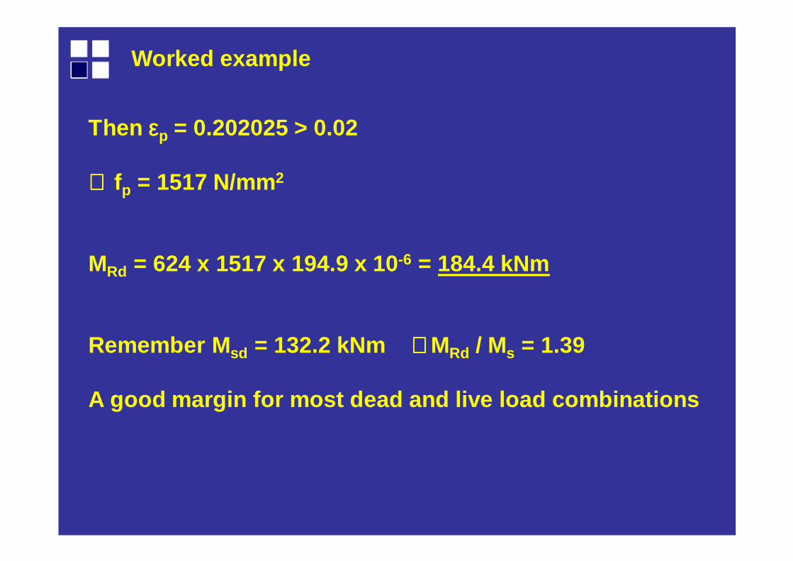
Then εεεεp = 0.202025 > 0.02
∴∴∴∴ fp = 1517 N/mm2
MRd = 624 x 1517 x 194.9 x 10 -6 = 184.4 kNm
Remember M sd = 132.2 kNm ∴∴∴∴MRd / Ms = 1.39
A good margin for most dead and live load combinati ons
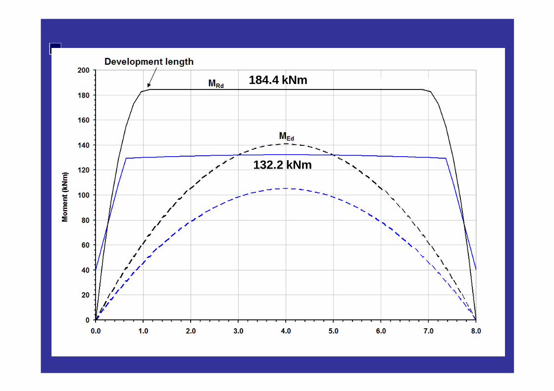
184.4 kNm
132.2 kNm

Syllabus
Camber.Creep.Deflections.Limits.
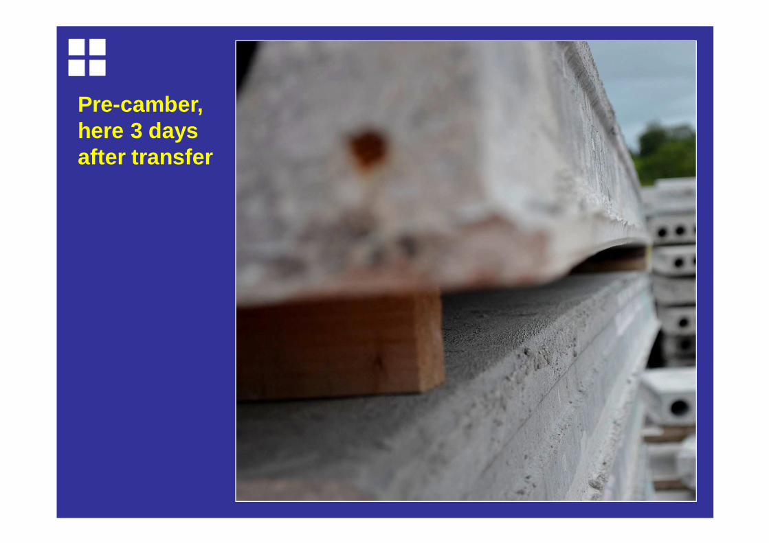
Pre-camber, here 3 days after transfer
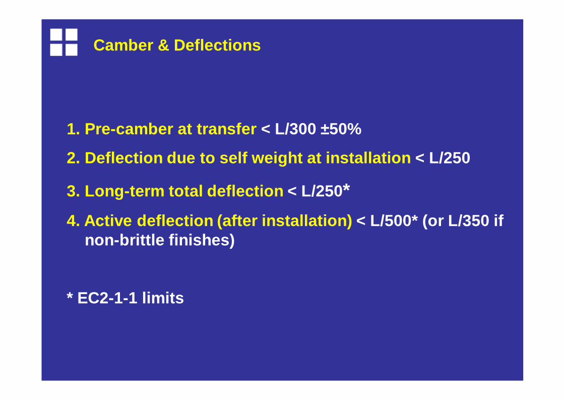
Camber & Deflections
1. Pre-camber at transfer < L/300 ±50%
2. Deflection due to self weight at installation < L/250
3. Long-term total deflection < L/250*
4. Active deflection (after installation) < L/500* (or L/350 if non-brittle finishes)
* EC2-1-1 limits
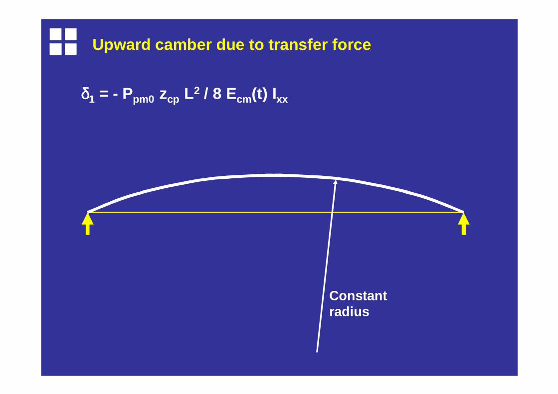
Upward camber due to transfer force
δδδδ1 = - Ppm0 zcp L2 / 8 Ecm(t) Ixx
Constant radius
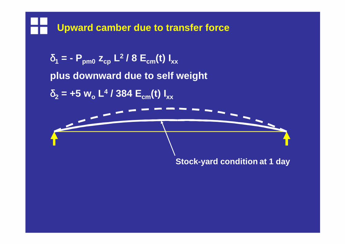
Upward camber due to transfer force
δδδδ1 = - Ppm0 zcp L2 / 8 Ecm(t) Ixx
plus downward due to self weight
δδδδ2 = +5 wo L4 / 384 Ecm(t) Ixx
Stock-yard condition at 1 day
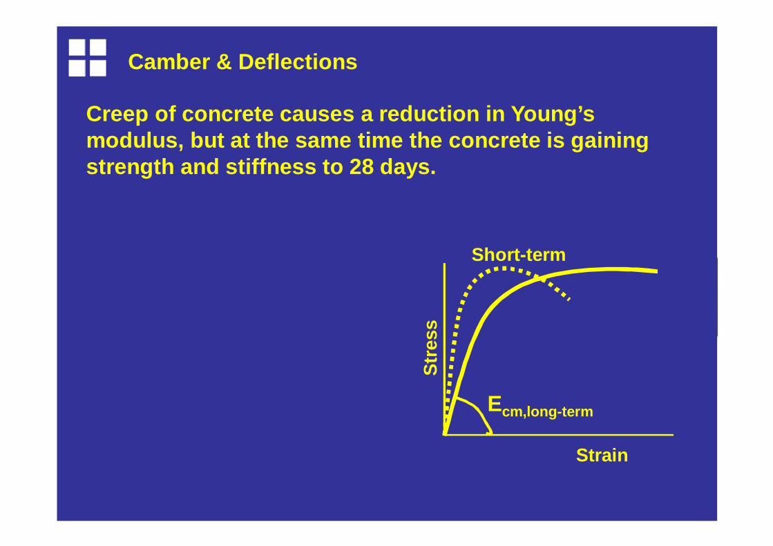
Camber & Deflections
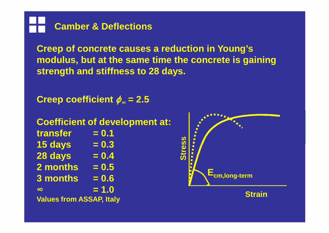
Creep of concrete causes a reduction in Young’s modulus, but at the same time the concrete is gaini ng strength and stiffness to 28 days.
StrainS
tres
sEcm,long-term
Short-term
Camber & Deflections
Creep of concrete causes a reduction in Young’s modulus, but at the same time the concrete is gaini ng strength and stiffness to 28 days.
Creep coefficient ϕϕϕϕ∞ = 2.5
Coefficient of development at:transfer = 0.115 days = 0.328 days = 0.42 months = 0.53 months = 0.6∞ = 1.0Values from ASSAP, Italy
StrainS
tres
sEcm,long-term
Camber & Deflections
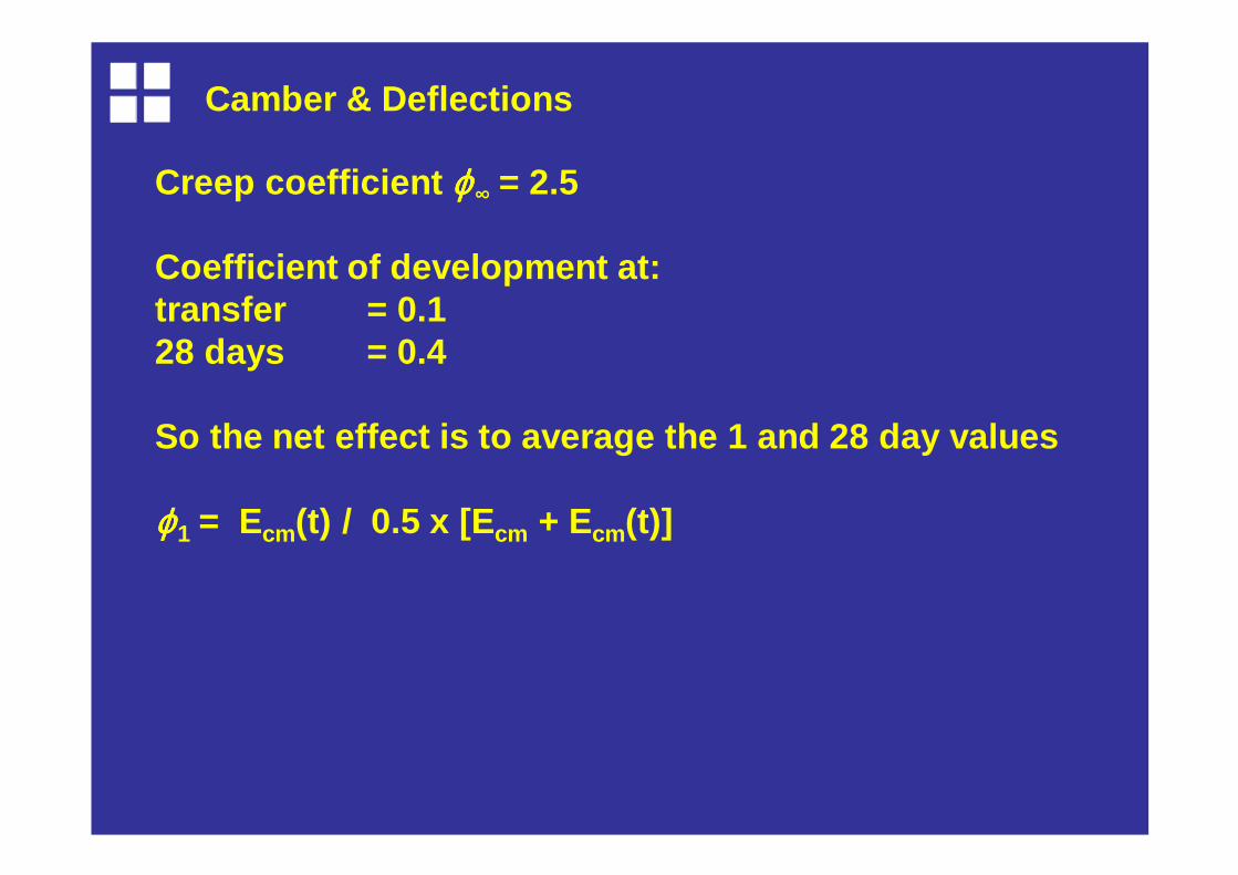
Creep coefficient ϕϕϕϕ∞ = 2.5
Coefficient of development at:transfer = 0.128 days = 0.4
So the net effect is to average the 1 and 28 day va lues
ϕϕϕϕ1 = Ecm(t) / 0.5 x [E cm + Ecm(t)]
Camber & Deflections
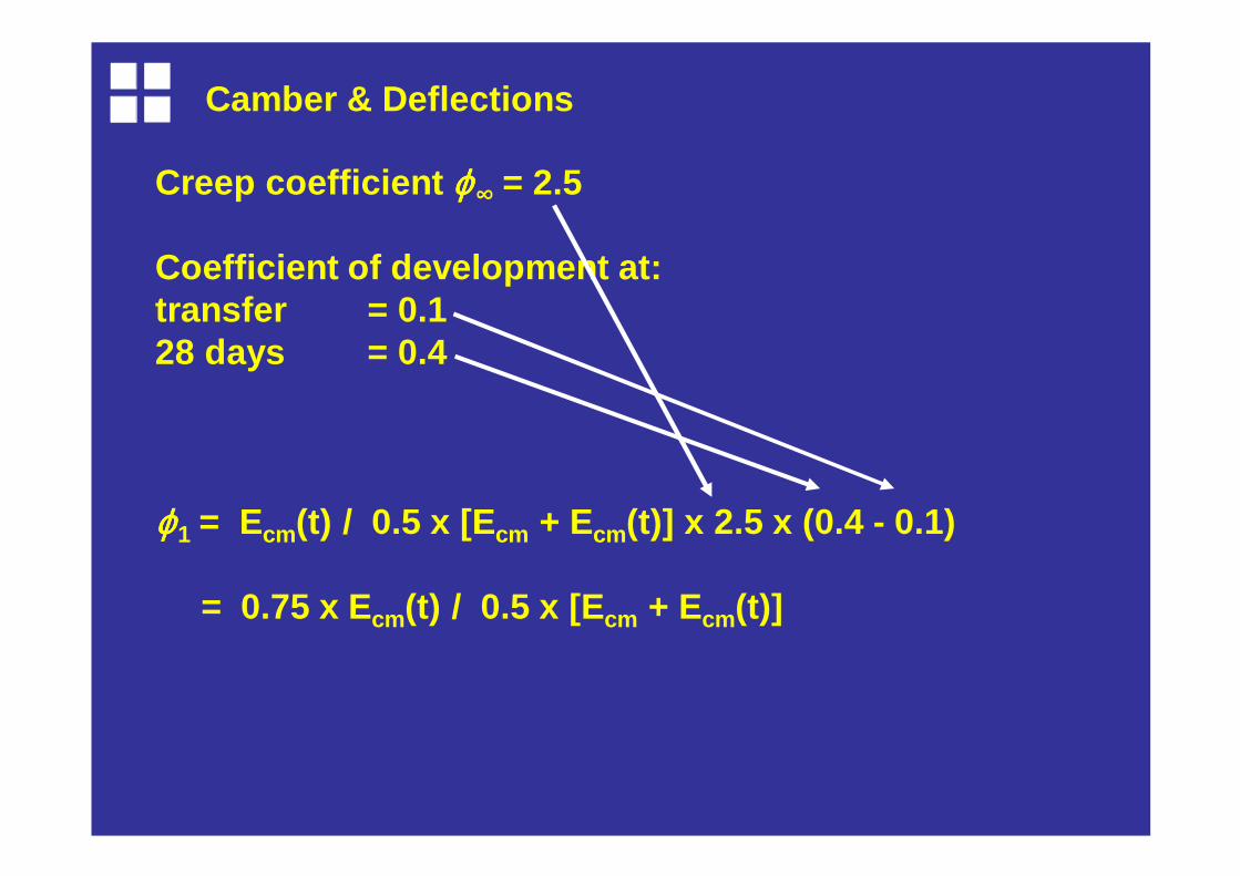
Creep coefficient ϕϕϕϕ∞ = 2.5
Coefficient of development at:transfer = 0.128 days = 0.4
ϕϕϕϕ1 = Ecm(t) / 0.5 x [E cm + Ecm(t)] x 2.5 x (0.4 - 0.1)
= 0.75 x Ecm(t) / 0.5 x [E cm + Ecm(t)]
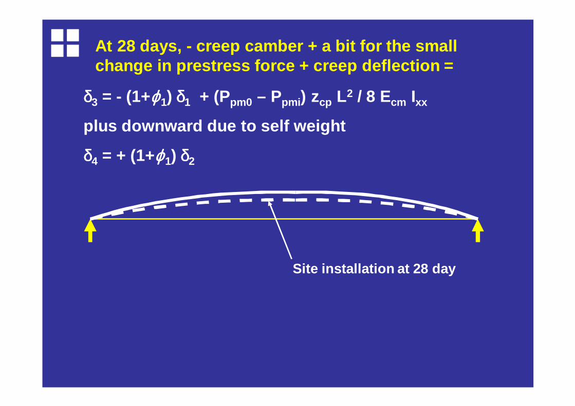
At 28 days, - creep camber + a bit for the small change in prestress force + creep deflection =
δδδδ3 = - (1+ϕϕϕϕ1) δδδδ1 + (Ppm0 – Ppmi ) zcp L2 / 8 Ecm Ixx
plus downward due to self weight
δδδδ4 = + (1+ϕϕϕϕ1) δδδδ2
Site installation at 28 day
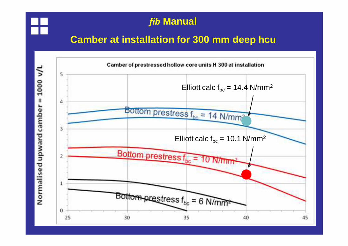
fib Manual
Camber at installation for 300 mm deep hcu
Elliott calc fbc = 10.1 N/mm2
Elliott calc fbc = 14.4 N/mm2
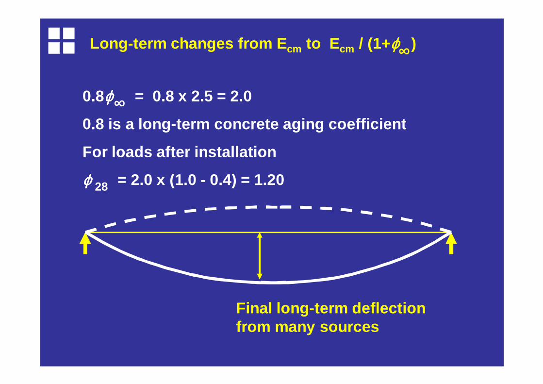
Long-term changes from E cm to E cm / (1+ϕϕϕϕ )∞
0.8ϕϕϕϕ = 0.8 x 2.5 = 2.0
0.8 is a long-term concrete aging coefficient
For loads after installation
ϕϕϕϕ = 2.0 x (1.0 - 0.4) = 1.2028
Final long-term deflection from many sources
∞
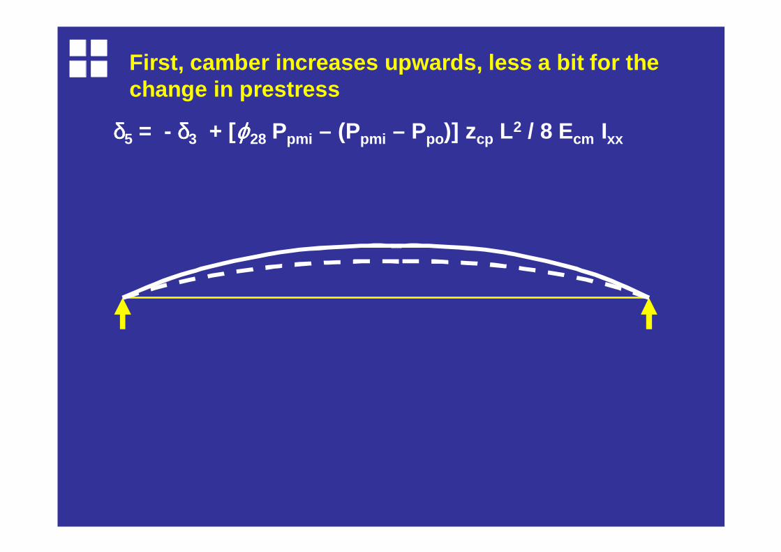
δδδδ5 = - δδδδ3 + [ϕϕϕϕ28 Ppmi – (Ppmi – Ppo)] zcp L2 / 8 Ecm Ixx
First, camber increases upwards, less a bit for the change in prestress

δ5 = - δ3 + [ϕ28 Ppmi – (Ppmi – Ppo)] zcp L2 / 8 Ecm Ixx
δδδδ6 = + δδδδ4 + 5 w1 ϕϕϕϕ28 L4 / 384 Ecm Ixx
..then self weight creeps down, 2 nd term is the creep
δ5 = - δ3 + [ϕ28 Ppmi – (Ppmi – Ppo)] zcp L2 / 8 Ecm Ixx
δ6 = + δ4 + 5 w1 ϕ28 L4 / 384 Ecm Ixx
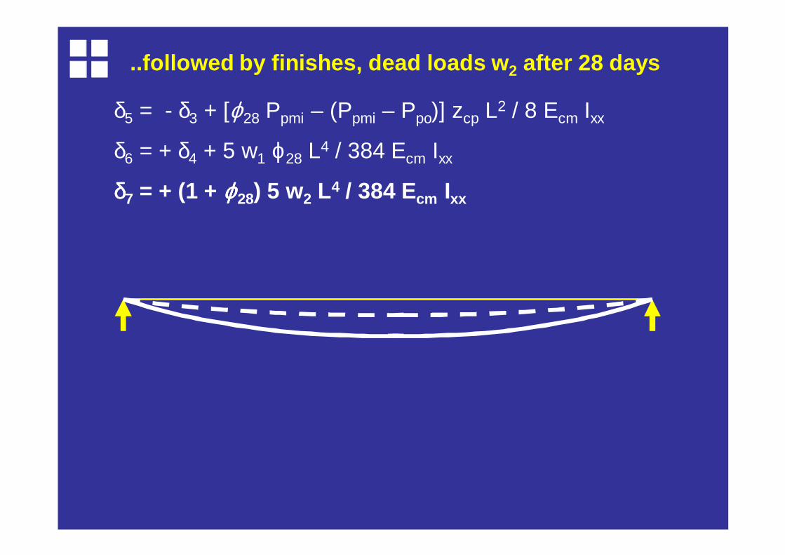
δδδδ7 = + (1 + ϕϕϕϕ28) 5 w2 L4 / 384 Ecm Ixx
..followed by finishes, dead loads w 2 after 28 days
δ5 = - δ3 + [ϕ28 Ppmi – (Ppmi – Ppo)] zcp L2 / 8 Ecm Ixx
δ6 = + δ4 + 5 w1 ϕ28 L4 / 384 Ecm Ixx
δ7 = + (1 + ϕ28) 5 w2 L4 / 384 Ecm Ixx
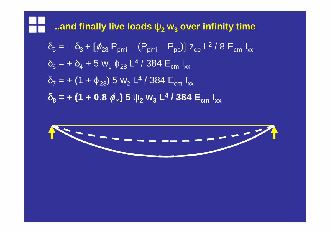
δδδδ8 = + (1 + 0.8 ϕϕϕϕ∞) 5 ψψψψ2 w3 L4 / 384 Ecm Ixx
..and finally live loads ψψψψ2 w3 over infinity time
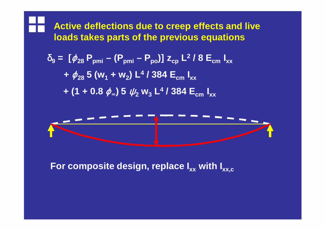
δδδδ9 = [ϕϕϕϕ28 Ppmi – (Ppmi – Ppo)] zcp L2 / 8 Ecm Ixx
+ ϕϕϕϕ28 5 (w1 + w2) L4 / 384 Ecm Ixx
+ (1 + 0.8 ϕϕϕϕ∞) 5 ψψψψ2 w3 L4 / 384 Ecm Ixx
Active deflections due to creep effects and live loads takes parts of the previous equations
For composite design, replace I xx with I xx,c

Worked example (continued)
Calculate camber, installation and long-term deflec tion
8.0 m effective span

Worked example
Self weight = 182791 x 24.5 x 10 -6 = 4.48 kN/m
Dead loads = 3.0 kN/m 2 = 3.60 kN/m per unit
Use of floor = offices, then ψψψψ2 = 0.3
Live load = 0.3 x 4.0 = 1.2 kN/m 2 = 1.44 kN/m per unit
Worked example
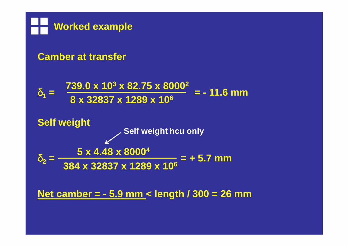
Camber at transfer
δδδδ1 = = - 11.6 mm 739.0 x 103 x 82.75 x 8000 2
8 x 32837 x 1289 x 10 6
Self weight
δδδδ2 = = + 5.7 mm
Net camber = - 5.9 mm < length / 300 = 26 mm
5 x 4.48 x 8000 4
384 x 32837 x 1289 x 10 6
Self weight hcu only
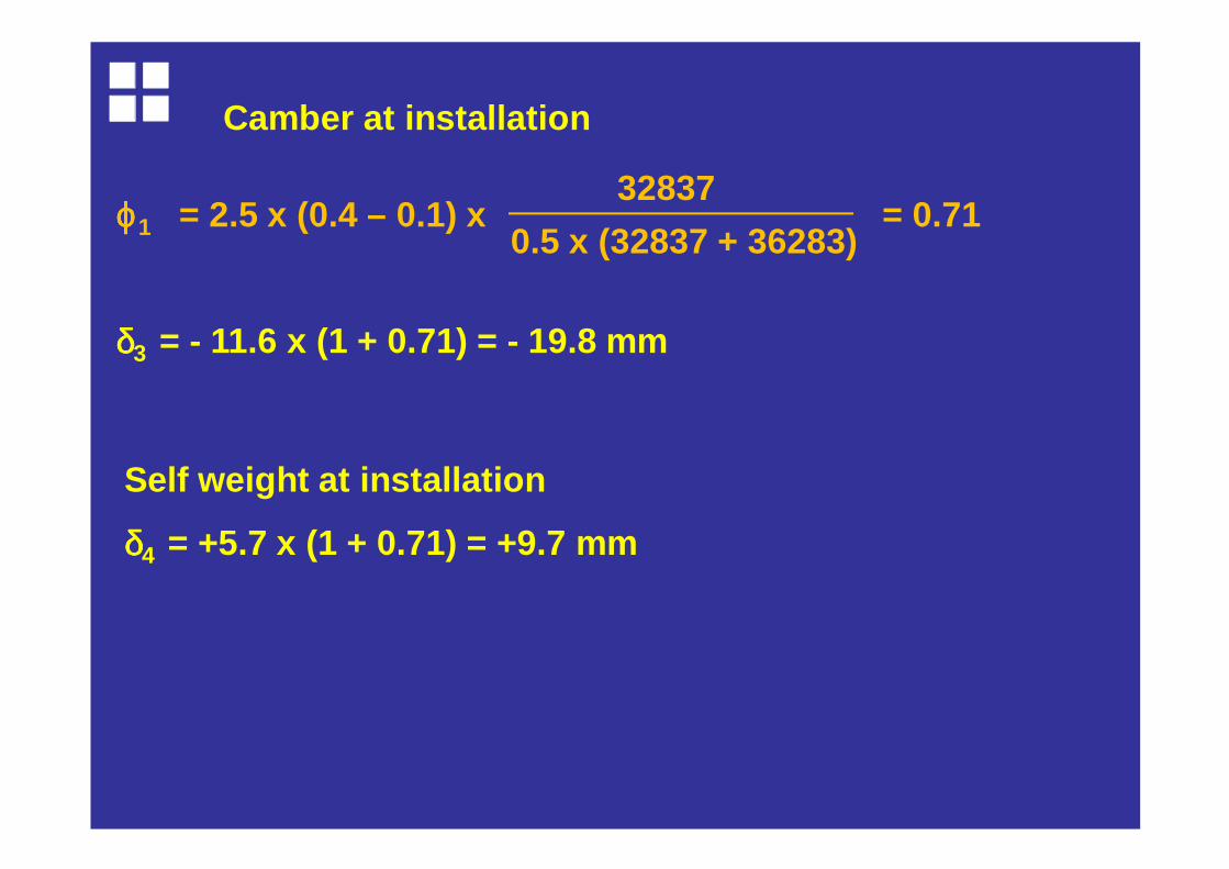
ϕϕϕϕ1 = 2.5 x (0.4 – 0.1) x = 0.71
δδδδ3 = - 11.6 x (1 + 0.71) = - 19.8 mm
32837
0.5 x (32837 + 36283)
Camber at installation
Self weight at installation
δδδδ4 = +5.7 x (1 + 0.71) = +9.7 mm
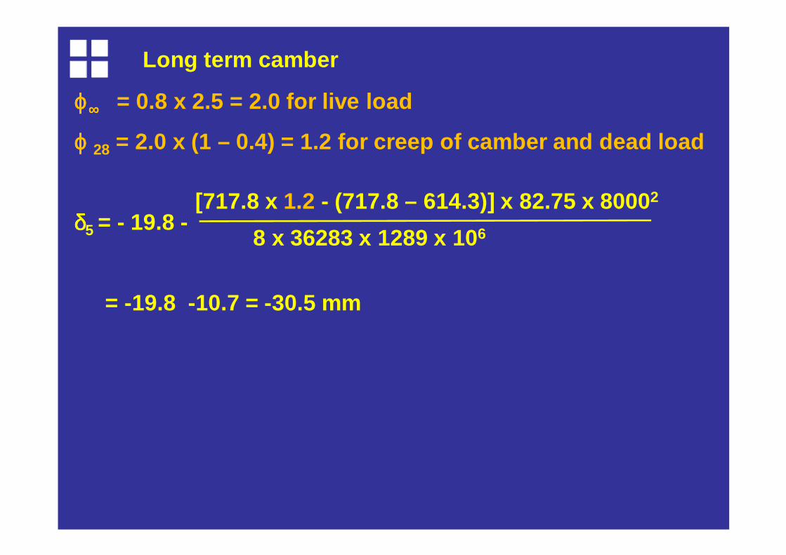
ϕϕϕϕ∞∞∞∞ = 0.8 x 2.5 = 2.0 for live load
ϕ ϕ ϕ ϕ 28 = 2.0 x (1 – 0.4) = 1.2 for creep of camber and dead load
δδδδ5 = - 19.8 -
= -19.8 -10.7 = -30.5 mm
[717.8 x 1.2 - (717.8 – 614.3)] x 82.75 x 8000 2
8 x 36283 x 1289 x 10 6
Long term camber
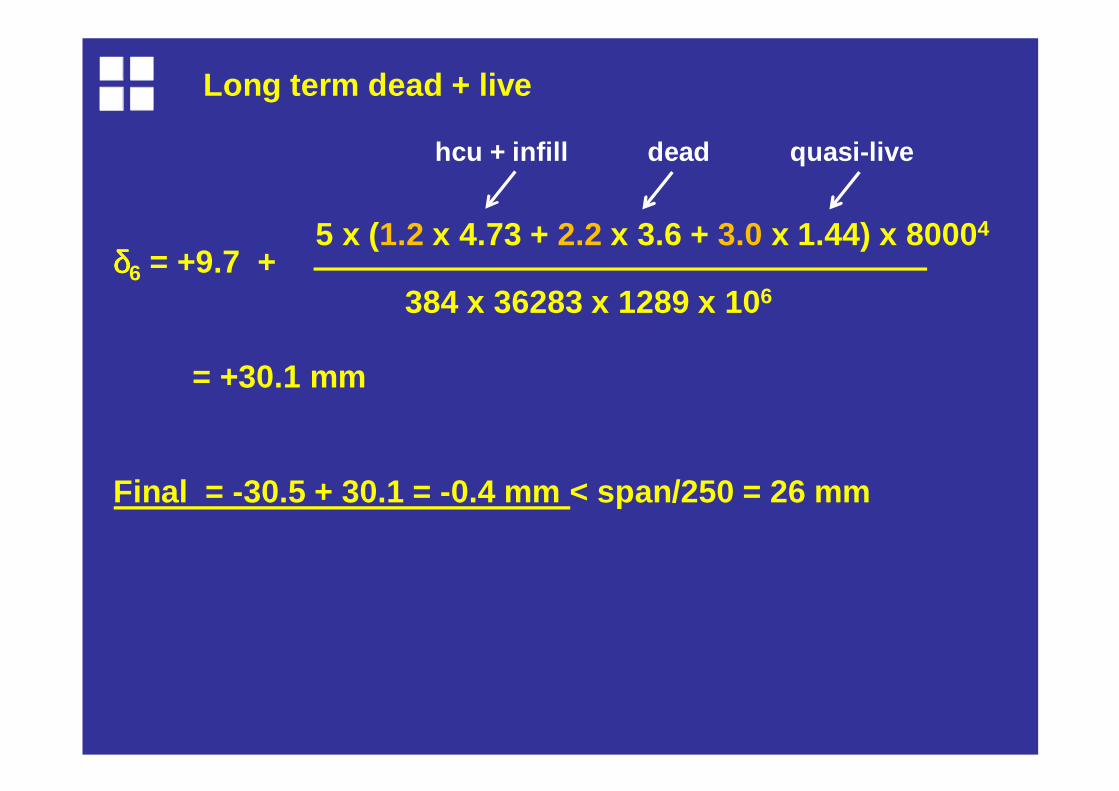
δδδδ6 = +9.7 +
= +30.1 mm
Final = -30.5 + 30.1 = -0.4 mm < span/250 = 26 mm
384 x 36283 x 1289 x 10 6
5 x (1.2 x 4.73 + 2.2 x 3.6 + 3.0 x 1.44) x 8000 4
hcu + infill dead quasi-live
Long term dead + live
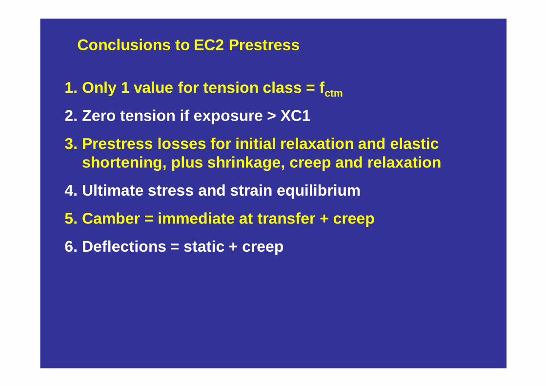
Conclusions to EC2 Prestress
1. Only 1 value for tension class = f ctm
2. Zero tension if exposure > XC1
3. Prestress losses for initial relaxation and elast ic shortening, plus shrinkage, creep and relaxation
4. Ultimate stress and strain equilibrium
5. Camber = immediate at transfer + creep
6. Deflections = static + creep
Related Documents