Sarda Energy & Minerals Ltd 1 Pre Feasibility Project Report PROPOSED INSTALLATION of 10 NOS. OF COAL GASIFIERS - 27046 Nm 3 /hr. (Fuel Replacement for Operational 0.6 MTPA Pellet Plant) MODERNIZATION OF 0.7 MTPA IRON ORE GRINDING UNIT TO 1.0 MTPA IRON ORE GRINDING & BENEFICIATION PLANT of SARDA ENERGY & MINERALS LIMITED PHASE-I OF SILTARA INDUSTRIAL GROWTH CENTRE, MANDHAR, DISTRICT – RAIPUR (C.G.) Ph: 0771- 2214210

Welcome message from author
This document is posted to help you gain knowledge. Please leave a comment to let me know what you think about it! Share it to your friends and learn new things together.
Transcript
Sarda Energy & Minerals Ltd
1
Pre Feasibility Project Report
PROPOSED INSTALLATION of 10 NOS. OF COAL GASIFIERS - 27046 Nm3/hr.
(Fuel Replacement for Operational 0.6 MTPA Pellet Plant)
MODERNIZATION OF 0.7 MTPA IRON ORE GRINDING UNIT TO 1.0 MTPA
IRON ORE GRINDING & BENEFICIATION PLANT
of
SARDA ENERGY & MINERALS LIMITED
PHASE-I OF SILTARA INDUSTRIAL GROWTH CENTRE, MANDHAR,
DISTRICT – RAIPUR (C.G.)
Ph: 0771- 2214210
Sarda Energy & Minerals Ltd
2
Chapter – 1
Executive Summary
1.1 EXECUTIVE SUMMARY
1.1.1 Report objective
M/s. Sarda Energy & Minerals Ltd. (Formerly M/s Chhattisgarh Electricity Company)
had established a 0.6 MTPA Pelletization plant at Phase – I of Siltara Industrial Growth
Center at village Mandhar, Raipur which is under operation since 07.10.2009.
Sarda Energy & Minerals Limited has envisaged for establishment of following projects
as backward integration to its existing operational 0.6 MTPA Pellet Plant:
1. Expansion of 7,00,000 TPA Iron ore Grinding Unit to 10,00,000 TPA Iron Ore Grinding & Beneficiation Plant
2. Installation of 27046 Nm3/Hr. Coal Gasifiers (10 Nos) (Fuel Replacement of
Operational 0.6 MTPA Iron Ore Pellet Plant)
The report is being prepared describing the details of operation process, plant and machinery, Material balance, Water Balance Cost of Project, Land requirement and Man
Power Requirement etc.
1.1.2 Report Summary:
The basis of selection of major equipment including a review of technologies and their
evaluation is indicated in the report. The chapter in the report also deals with the annual
requirement of raw material.
The project report also covers the plant facilities and plant description for coal Gasifier
and Iron Ore Grinding and Beneficiation plant.
The detailed process description of all the system has been covered in the project report.
The chapter in the project report deals with the facilities provided for the plant water
system and other utilities such as fuel etc. The pollution control measures proposed for
Coal Gasifier and Iron Ore Grinding & Beneficiation plant are also described in the
chapter of the report.
The chapter of the report also includes the organization and manpower for the proposed
10 Nos Coal Gasifier with total capacity of 27,046 Nm3/Hr. and 10,00,000 TPA Iron Ore
Grinding & Beneficiation plant.
The estimates of capital cost, annual manufacturing expenses and the financial analysis of
the project are presented in the report.
Sarda Energy & Minerals Ltd
3
1.2 PROJECT AT A GLANCE
1.2.1 COMPANY DETAILS
Company’s name : Sarda Energy & minerals Ltd.
Address
Telephone No.
Fax No.
E-mail Address
Phase-I, Industrial Growth Center, Siltara,
: Village - Mandhar
Raipur (Chhattisgarh) 493 111
: (0771) 403925 to 29
: (0771) 403924 / 33
1.2.2 BOARD OF DIRECTORS
Board of directors : Mr. K.K. Sarda, (B.E.)
Smt. Uma Sarda
Mr. Pankaj Sarda, (B.E, MS-USA)
Mr. P. K. Jain
Mr. Prabhakar Ram Tripathi
Mr. Rakesh Mehra
Mr. Asit Kumar Basu
Mr. G.S.Sahani Mr.Jitender Balakrishnan
1.2.3 SITE DETAILS
Project Location : Phase-I of Siltara Industrial Growth Centre,
Village - Mandhar, Raipur (C.G.)
Nearest Railway Station : Mandhar – 1.5 Kms.
Nearest Airport : Raipur – 30 Kms.
Road Access : National Highway No.200 - 5 Km.
Nearest Sea Port : Visakhapatnam –500Kms.
Altitude : 289.5 Meters
Latitude : 21o 22’ 22” – North
Longitude : 81o 41’ 31” East
Wind data : Max. 60 Kms. Per hour
Rainfall : 40” – 60” (June – September)
Temperature
-Minimum : 7oC
-Maximum : 46oC
Sarda Energy & Minerals Ltd
4
1.2.4 PROJECT DETAILS
SEML has established and is operating a 6,00,000 TPA Pelletization Plant at Phase-I,
Siltara Industrial Growth Center, Mandhar which was commissioned in the year 2009.
The company has envisaged establishing the following projects as a part of backward
integration for the 0.6 MTPA Pellet Plant:
A. Expansion of 7,00,000 TPA Iron ore Drying and Grinding to 10,00,000 TPA
Iron Ore Grinding & Beneficiation Plant
B. Installation of Coal Gasifiers (10 Nos) 27046 Nm3/Hr. (Fuel Replacement of
Operational 0.6 MTPA Iron Ore Pellet Plant)
Expected date of Commercial Production
Proposed Expansion
1. 10 Nos Gasifier Plant January 2018
2. 7,00,000 TPA Iron Ore Grinding Unit to
10,00,000TPA Iron Ore Grinding &
Beneficiation Plant
January 2018
Sarda Energy & Minerals Ltd
5
Chapter – 2
2.1 Company Background
Sarda Energy & Minerals Ltd. (Formerly Chhattisgarh Electricity Company Ltd.),
Incorporated on 23rd January 1998, is a Public Limited Company. The company has a
Pellet plant of capacity 0.6 MTPA. The Company had installed 20 MW coal based
thermal power plant, which commenced operations in the year 2001, gradually the
capacity of power plant has been increased to 81.5 MW. The Company also installed five
9 MVA Submerged Arc Ferro alloys furnaces in phases to use captive power from power
Plant and to have maximum realization for the power generated presently total capacity
of plant is 45 MVA, which makes company the second largest producer of manganese
based Ferro Alloys in the country. The facilities are installed at Industrial Growth Centre,
Siltara, Raipur over an area of about 70 acres. Chhattisgarh Electricity Company Ltd. has
got merged with Raipur Alloys & Steel Limited as per the orders of Hon’ble High Court
of Chhattisgarh, Bilaspur dated 11th May, 2007 & the name of Raipur Alloys & Steel
Limited has also been changed to “Sarda Energy & Minerals Limited” (SEML) as per
Fresh Certification of Incorporation dated 2nd August 2007. Liberalization of economy
by the Government, throwing open for manufacturing of Iron and Steel including mining
of iron ore, coal and other related minerals to private entrepreneurs, provided an avenue
for further growth in this segment to SEML. Company is a industrial house to set up a
modern integrated steel plant at Siltara Industrial Estate, Raipur. The steel plant uses non-
coking coal for sponge iron production of 79,200 TPA, further it has expanded to
4,60,000 TPA sponge iron production. Initially for meeting its requirement for 79,200
TPA sponge iron, SEML obtained a mining lease for iron ore situated at Dongarbor in the
Rajnandgaon District, to produce 2.0 lakhs TPA. After expansion of sponge iron plant to
meet its requirement of iron ore, the company has increased production capacity of
Dongarbor Iron Ore Mine from 2.0 lakhs TPA to 15.0 lakhs TPA for extraction of iron
ore in the year 2007. Company has been allotted a captive coal block at Karwahi near
Tamnar, District-Raigarh, and Chhattisgarh State to produce 1.2 Million TPA coal.
Company is having underway project for installation of 1.1 Million TPA Integrated Steel
Plant and 60 MW WHRB Power Plant at Siltara Industrial Growth Centre, Mandhar, and
Raipur.
Sarda Energy & Minerals Ltd
6
PRESENT MANUFACTURING FACILITIES
The present manufacturing facility of the Company is situated at Phase-I, Siltara
Industrial Growth Centre, Siltara, Raipur and other districts in Chhattisgarh and
comprises of the following:
S.N. Facility Capacity
1 Sponge Iron 4,60,000 TPA (with WHR facility)
2 Steel Melting 3,60,000 TPA
3 Ferro Alloys 5 X 9 MVA Furnaces
( 90,000 TPA)
4 Power Plant 81.5 MW
5 Rolling Mill 1,80,000 TPA
6 Pellet Plant at Mandhar 6,00,000 TPA
7 Iron Ore Mine at Rajnandgaon 1.5 Million TPA
PATENT
The Company is marketing TMT bars under its registered trademark “Hytech” which
has got tremendous response from the corporate sector due to its quality. The company
has also got Patent for its Special Design Steel Bar that is registered in class 25-99 at
design no. 198260. The patent is valid for an initial period of 10 years and may be
extend for a further period of five years.
CAPITAL STRUCTURE
The Authorized capital of the Company is Rs. 50 Crores and the present issued and paid up capital is Rs. 35.95 Crores.
BANKERS
The Company is banking with Union Bank of India, Bank of Baroda, UCO Bank
and UTI Bank under consortium.
LISTING
The Company is currently listed on the Bombay Stock Exchange and is traded under
scrip id. SARDAEN.
CREDIT RATING
Short Term Rating given by CARE is “PR+1”, the highest rating. Long Term Rating given by CARE is “AA-“.

Sarda Energy & Minerals Ltd
7
SHAREHOLDING PATTERN
The promoters of the Company hold around 69% shares and the remaining is held by
FII’s, Banks, Corporate Bodies and public.
2.2 MANAGEMENT
BOARD OF DIRECTORS
Kamal Kishore Sarda, aged 57 years, B.E.(Mech.) is Chairman & Managing Director of
the Company. He has more than 32 years industrial experience and has a brilliant track
record. He stood 1st in SSC Merit in M.P. and 2
nd in B.E. (Mech.) Merit. He has also
completed course on Strategic Management from IIM, Ahmadabad. He has traveled
extensively across the world to study & observe new developments & trends in the
industry. He is the Ex-Chairman of CII, Chhattisgarh Chapter.
Pankaj Sarda, aged 30 years is an Industrial Engineer from Nagpur University and has
also completed Masters’ Degree in Science in Industrial Administration from Purdue
University. He has an experience of 7 years in the field of Corporate Affairs and
Management. He has been appointed as Whole time Director W.e.f. 1st November, 2007.
Mr. P.K. Jain CA, CS aged 49 years is Chief Financial Officer with Sarda Energy &
Minerals Ltd. He is having more than 25 years of experience of accounts and banking and
is associated with SEML for last more than 15 years. He is in-charge for company’s
accounting, financial, secretarial and taxation matters
Prabhakar Ram Tripathi, aged 65 years, is an authority on mine management and
mineral Grinding. He earned honors in Bachelors of Science in Mining Engineering from
Indian School of Mines, Dhanbad, Jharkhand, India. He also earned his First Class Mines
Manager's Certificate under coal mines regulation. Former Chairman & Managing Director
of National Mineral Development Corporation (NMDC), he has more than 47 years
experience in the field of mining and related activities. He is recognized as a leading
management practitioner in India and has also contributed to development of management
excellence through association with All India Management Association and National HRD
Network.
Rakesh Mehra, aged 56 years, FCWA, is Ex-General Manager of MPAVN. He is a
Financial Consultant and serves as a Professional director on the Board of many
Companies.
Asit Kumar Basu, aged 59 years is B.M.E. with rich experience in the field of finance.
He is Ex-CGM, IDBI.
Sarda Energy & Minerals Ltd
8
G.S. Sahani, aged 62 year is a Former Director General of Shipping, Govt. of India and
Former Secy. (Coordination), Cabinet Secretariat, Govt. of India.
2.3 Need for the project and its importance to the country and/ or region
The need for Iron Ore Beneficiation Plant as a part of the iron making facility requires to
be carefully evaluated particularly due to the runaway increase in iron ore prices and
shortage of Iron ore in the recent year in India.
Coal - The fuel utilized in the Pelletization Plant is High Grade Imported Coal/Coke. By
utilizing the domestic coal in pellet plant through Gasification. The companies will not
only deficit the BOP of the country and also reduce the Sulphur emission generated from
combustion of High Grade Imported Coal/Coke.
Iron Ore Fines – Utilization of unusable abundantly available low grade iron ore fines in
the process of steel making.
In view of the above, M/s Sarda Energy & Minerals Limited has proposed Installation of
Coal Gasifiers and Iron Ore grinding & beneficiation plant.
2.4 Demand -Supply Gap
Steel Industry in India is on an upswing because of the strong global and domestic
demand. India’s rapid economic growth and soaring demand by sectors like
infrastructure, real estate and automobiles, at home and abroad, has put Indian steel
industry on the global map. According to the latest report by International Iron and Steel
Institute (IISI), India is the seventh largest steel producer in the world. The current status
of iron ore and its future prospects have direct relationship mainly with steel production
in India. The total iron ore resources in India are approximately 25,249 Million tons (out
of which Hematite constitutes 14,630 MT and Magnetite constitutes 10,619 MT). Out of
the total production, 56% of iron ore production comes out as fines and 44% as boulders
which have to be sized to 10-30 mm for blast furnaces and 6-18 mm for sponge iron
plants. Iron ore in a finely ground state is not easily transported or readily processed.
Thus it is necessary to agglomerate the fine ground ore into pellet using binders.
2.5 Cost of Project:
Since the report includes a project which is already under operation the Cost of Project.
Thus, for the established unit the Gross Capital Made has been considered as Cost of
project and for the other two it is estimated based on enquiries floated, quotations
Sarda Energy & Minerals Ltd
9
received. The financing and pre-operative cost has been considered based on the
proposed financial package.
The estimated cost thus evaluated to be is Rs 12.789 Crores including pre-operative
expenses and margin money for working capital requirements
Cost of Capital
All Fig Lac Rs
Sl No Particular Amount
1 Iron Ore Grinding & Beneficiation Plant 8202
2 10 NO Coal Gasifier 4587
# Total 12789
2.6 Employment Generation (Direct and Indirect) due to Project
The major benefit due to the proposed expansion project will be in the sphere of
generating direct employment for about 252 persons in that area. The proposed project
will benefit local population. The manpower requirements for the operational phase of
the proposed Plant will be about 252 people. In addition, there will be an indirect
employment for skilled/ semi skilled people during project life. All attempts will be made
to employ suitable, locally available, skilled personnel from the nearby area. In case of
non-availability of skilled persons, people will be employed from outside area.
Manpower Estimate
It is estimated that the total requirement of manpower for the whole organization will be
approximate 252. Department-wise /division-wise manpower is given as under. The manpower has been divided into the following categories:
- Managerial
- Executive
- Supervisory - Skilled (SK)
Department Total
Administration 5
Works Office 10
Raw Material Handling System 30
Gasifies 37
Grinding & Beneficiation 65
Stores 15
Utilities & Services 20
Maintenance 70
Total 252
Sarda Energy & Minerals Ltd
10
Chapter – 3
3.1 Type of project
Existing and Proposed Projects at Mandhar Village
SEML had obtained consent for installation of existing 6,00,000 TPA Pelletization
Plant from CECB and plant was commissioned in the year 2009.
The company is applying for Grant of Environment Clearance for Flowing:
A. Expansion of 7,00,000 TPA Iron ore Drying and Grinding to 10,00,000 TPA Iron Ore
Grinding & Beneficiation Plant
B. Installation of Coal Gasifiers (10 Nos) 27046 Nm3/Hr. (Fuel Replacement of
Operational 0.6 MTPA Iron Ore Pellet Plant)
3.2 Location (map showing general location, specific location, and project boundary and
project site layout) with coordinates
Company has been allotted 204.452 Hectares of land at village Mandhar, Phase-I of Siltara
Industrial Growth Centre, Raipur for installation of 1.1 MTPA Integrated Steel Plant and
60MW WHRB power plant. The site is located within 21o 22’ 22” – North Latitude, and 81
o
41’ 31”- East Longitude. It is located centrally vis-à-vis source of raw material as well as
Sponge Iron consuming industry. The map showing general Location of the proposed
Project and Project site layout plan is shown below.

Sarda Energy & Minerals Ltd
11
Sarda Energy & Minerals Ltd
Project
Site
Location
Fig. - Map Showing General Location

Sarda Energy & Minerals Ltd
12
STP
10,00,000 TPA IRON ORE GRINDING & BENEFICIATION
PLANT
AREA FOR FUTURE EXPANSION33
L E G E N D:-
PROPOSED EXPANSION
1
R OAD
Pl an ts
Stack Pelletizing E.S.P
Co al
Proportioning Bins
Sto rage
6
900015900 180001320015000132009800 8000 10500 11000 12000 12000
9 000
Pul v eri zi ng
O IL TANK
32
GAS OUTLET
TO GR
ATE-OVEN
3
19
3
RAJENDRA S
TEEL
OPEN A
REA
RAJENDRA STEEL
(IN SIDE BOUNDRY WALL)
Diverted
Appro
ach R
oad
Line
SEM
L LAND
BOU
ND
ARY
Property
Line
HT
TOWER
HT
TOWER
HT
TOWER
EXIS
TIN
G H
T L
INE
Property
POND
EX
G.
CA
NA
L
21
27
15
2
DM & SW
Plant
Dn400 MW
Dn 200
Dn 200
Dn65 CWDn65 DW
Dn 300
11
302.5
Dn40 DW
Reducer
Canal
Raw Water Reservoir
GREEN BELT AREA
Raw Water Reservoir
9m
MRSS
Raw Water Reservoir
Rain Water Harvesting Pond
Adm Building
Officer's Canteen
LBSS-1
AUXILIARY FACILITIES:
13
12
11
10
9
8
7
Stores14
Diesel Tank15
Weigh Bridge16
Raw Material Laboratory17
EXISTING PLANT & FACILITIES
L E G E N D:
Pellet Plant - 600000 TPA1
Flux & Coke Crushing18
Railway Yard
Raw Material Stockyard3
2
L E G E N D:
UNDERWAY PROJECTS:
Rolling Mill - 350000
Steelmelt Shop 4
5
1- Electric Arc Furnace - (2x 40 Ton) 500000 TPA
2- CCM (2x3 Strand) 470000Chimney19
Chimney19
Air Vent20
Coke Oven (Non Recovery) - 520000 21
Blast Furnace (2x450Cu.M) - 790000
Sinter Plant (2x60 m )- 1300000
1- Electric Arc Furnace (1x90 TON) - 600000
22
23
2 - CCM (1 x 4 Strand) - 600000
Power Plant (WHRB)- 2x30MW Coke Oven & B.F.
Rolling Mill - 60000025
26
Oxygen Plant - 2 x 150 TPD27
Steelmelt Shop24
20
20
4
25
19
19
19
20
1919
2
19 19 19
SARDA ENERGY & MINERALS LIMITED
28.05.14
SEML/MAN/PR/06
Unloading platform28
Raw Material Yard of SEML29
Office Complex For The Mills30
Central Ware House31
7,00,000 TPA IRON ORE DRYING & GRINDING TO 6
EXISTING COMMON FACILITIES:
10 NOS. COAL GASIFIER - 27046 Nm /hr.32
11
BORE WELL34
3411m
330m
GREEN BELT
9
SOLAR PLANT
3333
33

Sarda Energy & Minerals Ltd
13
3.3 Details of alternate sites considered and the basis of selecting the proposed site,
particularly the environmental considerations
As it is an expansion project no alternative sites were considered.
The following are the factors in favor of selection of site at village Mandhar:
- Easily availability of raw material
- Availability of power
- Availability of adequate water
- Availability of adequate land for locating the plant with approach roads
- Suitability of land from topography and geological aspects
- Proximity of National Highways & Transport of heavy equipments
The environmental consideration of the site is tabulated below:
Sr. No. Particulars Details
1. Latitude Between N 210 20’09.74” – N21
020’42.57”
2. Longitude Between E81041’10.57” - E81
0 42’02.48”
3. Altitude 282 m above MSL 4. Toposheet 64 G/11 5. Seismicity Area falls under least affected
earthquakes zone II as per IS 1893 - 1984
6. Climatic condition
(Annual Average)
Ambient Air temp 7oC to 46
oC
Avg. annual rainfall 1200 mm
7. Nearest village Mandhar
8. Nearest town Raipur
9. Nearest railway station Mandhar (1.5 KM)
10. Nearest airport Raipur (25 KM)
11. Streams / Rivers Kharoon
12. Sanctuaries /National Parks/
Biospheres, etc.
Nil
13. Topography Gently sloping
14. Defense Installations Nil
15. Historical Places Nil
16. Road Access NH 200 (5 KM)
Sarda Energy & Minerals Ltd
14
3.4 Project Area description
Plant Site
Company has been allotted 204.452 Hectares of land at village Phase-I of Siltara
Industrial Growth Centre, Mandhar, Raipur for installation of 1.1 MTPA Integrated Steel
Plant and 60MW WHRB power plant. Company has been allotted 204.452 Hectares of
land at village Mandhar, Phase-I of Siltara Industrial Growth Centre, Raipur for
installation of 1.1 MTPA Integrated Steel Plant and 60MW WHRB power plant. It is
located centrally vis-à-vis source of raw material as well as Sponge Iron consuming
industry.
STATEMENT OF AREA
SEML has in possession of 204.452 hectares of Land in Phase-I, Siltara Industrial
Growth Centre, Mandhar, for installation of 1.1 Million TPA Integrated Steel Plant along
with 2x30MW WHRB based Power Plant. The details of land area for existing, underway
and proposed expansion projects are shown in table given below:-
Composite Area Statement (in M2)
S.
No
Facility Existing Proposed
expansion
Total
1 Pellet Plant 15727 - 15,727
2 Iron Ore Grinding & Beneficiation Plant - 7971 7,971
3 Coal Gasifiers for Pellet Plant - 10150 10,150
3 Steel Melting Shop (EAF , LRF & CCM) 69500 - 69,500
4 Coke Oven 70000 - 70,000
5 Coal / Flux Crushing & Iron Ore
Handling
19000 - 19,000
6 Flux / Coke Crushing 15000 - 15,000
7 Sinter Plant 44250 - 44,250
8 Blast Furnace 69123 - 69,123
9 Rolling Mills 78000 - 78,000
10 Power Plant 50000 - 50,000
11 MRSS 20000 - 20,000
12 Oxygen Plant 14000 - 14,000
13 Administrative Building 8000 - 8,000
14 Store & Maintenance Building 8000 - 8,000
Sarda Energy & Minerals Ltd
15
15 Plant Water Reservoir 29650 - 29,650
16 Roads 80000 - 80,000
17 Raw Material Yard 88000 - 88,000
18 Railway Yard 58460 - 58,460
19 Greenbelt 600962 73730 674,692
20 Other 485274 28552 513,826
21 Area En marked for future Expansion - 101171 101,171
TOTAL 1822946 221574 2,044,520
TOTAL (HA) 204.452
3.5 Mechanical Equipments and Process Flow Diagram
3.5.1 Brief Process Description (Manufacturing Process):
Manufacturing Process of Proposed Coal Gasifier Plant
These Extended Shaft Gasifier are of distinctly improved design over the conventional 19th
Century old design single stage Gasifier with respect to quality and consistency of gas,
smooth and trouble free operation without interruptions, higher calorific value, adaptability
to lower grades of coal, safety and operation friendliness, ecology and pollution control,
easily controllable and flexibility of operation etc.
The object of the New Technology is to produce a clean consistent quality Producer Gas of
high Calorific Value from majority of grades of Indian Coal from ‘A’ to ‘G’ grade and with
faster rate of gasification or more coal through-put per unit grate area. With this objective
in view a deep coal bed was introduced with extension of shaft over the conventional
generator proper of the single stage design and the product gas has been fully diverted to
the top to come out from the top of the Gasifier. The advantages accrued from such
modifications are thus:
The Extended Shaft is so precisely calculated that the fuel coal while moving downwards get
stripped off its Volatile Matter to a great extent and the coal itself gets converted to ‘Near-
Coke’ state with an acquired advantage of greater reactivity for a faster gasification almost
similar to coke gasification. The product gas, on the other hand, while moving upwards,
counter-current to the incoming feed coal gets auto enriched with the stripped and distilled
volatile matter of coal to a higher calorific value. This novel feature had greatly improved the
kinetics of gasification, specific mass flow of gas per unit empty cross section of the Gasifier,

Sarda Energy & Minerals Ltd
16
gas make per MT of coal, calorific value, and consistency of gas quality and more stream
days of operation without interruption.
At the same time, coal bed of Extended Shaft helps to adsorb dusts soot etc of the product
gas and no extensive cleaning facilities are required for better and consistent quality of gas.
The Process is continuous and as controllable and maneuverable as oil firing.
The Process is Eco-friendly; the equipment is operation friendly and conforms to all PCB
norms.
GENERAL PROCESS DESCRIPTION WITH VARIOUS PROCESS STEPS AND
REACTIONS
Process steps and Reaction are:
Coal from ground buffer stock is lifted and delivered to the over head bunker by means of
an inclined Conveyor/bucket elevator and through a Vibrating Screen.
From the Bunker, Coal is fed to the extended shaft Gasifier through leak-proof
pneumatically operated double bell feeding system as per the specified exit temperature of
outlet PG not exceeding 140°C
After entering the Extended Shaft the feed coal passes through following steps and
gasification reactions:
Pre-heating, Drying and Distillation Zone.
Feed coal travels downwards and gets dried and preheated to the distillation temperature of
400°C to 500°C as per the modified temperature-profile. Due to prolonged stage of better
physical contact with coal interfaces, substantial heat transfer from gas to coal takes place
and at the same time high volatile matters of coal get stripped off and enter the gas phase,
in turn auto-carbureting the later.
After distillation zone, coal enters the Secondary Reduction Zone where it faces
oxidation and primary reducing gases and thereby Secondary Reduction reactions take
place as per the following equations:
C+CO2 =2CO
CO+H2O = CO2+ H2
Primary Reduction Zone:
The reactions are:
Sarda Energy & Minerals Ltd
17
C + H2O = CO + H2
C + 2H2O = CO2 + 2H2
C + CO2 = 2CO.
Oxidation Zone:
Coal oxidation or burning takes place in this zone with the standard oxidation of
carbon with generation of CO2
C + O2 = CO2
The reaction is highly exothermic and it provides heat to the reduction reaction which is endothermic. Steam, air and CO2 are carrier of heat for successive reactions in the
Reduction zones.
Ash zone:
Just below the oxidation zone there is ash zone. Air and steam at specified quantity,
which is described at later chapter, enter through the bottom skirt and pass through grate
rings and ash, where these gases pick up heat from the ash and thereby cool the ash which
thus protects the grate from intense heat of oxidation (about 1200° C). Air and steam on
the other hand get pre-heated for a faster and better oxidation. It is obvious that too much
extraction of Ash will damage the grate stool and too much accumulation of Ash will
shift the whole temperature profile upwards with reduction in distillation zone and upper
zone. The results are lower C.V Producer gas, more un-decomposed steam and more
quantity of dusts and soot in the product gas.
Hence maintaining the correct temperature-profile with a maximum outlet gas temperature
within 140° C is most important. The two gas streams with full quantity of Producer gas
coming out from the two gas off-takes run parallel up to the Mixing cum washing chamber
where this is washed with re-circulated water at 60° C to 70° C. The height of the chamber
and rate of circulation are such that the gas cannot be cooled down below the above
temperature and water vapor content remains much below the saturation quantity to avoid
more condensation of water vapor and volatile matters. From the washing chamber the
gas is connected to the common-header. The heavy tar and water collected at the bottom
of the washing chamber flows to the water circulation tank from where this is again
circulated to the washing chamber as described above. The heavy tar which gets settled at
the bottom of the settling tank to be drained to tar tank for further disposal.
For further removal of dust particulate matter the above gas is treated in Lim Washer and
for minimum tar content the gas is treated in electrostatic tar precipitator.

Sarda Energy & Minerals Ltd
18
Ecological Features of Gasifier
The basic Ecological features of Extended Shaft Gasifier are:
Gasifiers are operation friendly
The New Generation Producers are easy to operate and with proper instrumentation, the
control of various parameters like change in Coal through-put, addition of air for a
controlled Blast Saturation Temperature (BST), maintaining the mobility of coal – bed
and ash discharge system, regulating the coal through – put directly as per heat demand
through BST controller which is cascaded with air flow are all very simple. With proper
automation and instrumentation, less labor will be involved for the operations.
Safety Aspects
The Gasifiers are extremely safe to operate. With proper sealing arrangement of the coal
feeding system, poke-holes and ash-bowl, there is absolutely no gas-leakage to the
surroundings nor any emissions of particulate matters.
Against any over-pressure of the Gasifier, water seals are provided at desired locations.
High and low level alarms are provided on the jacket –boiler steam-drum.
Gasifiers are Eco-friendly
Extended Shaft Gasifier is fairly pollution-free. There are no gaseous or liquid effluents.
Heat radiation / loss is well guarded with the help of Cooling Jacket and glass wool
insulation on the bottom shell and refractory insulation in the Extended Shaft. So far as
liquid effluent is concerned, 0.5 to 1.5 MT of light tar per day is collected in the mixing
cum washing chamber. This is in a highly fluid state due to ingress of stripped volatile
matter of coal and its viscosity is almost similar to Furnace oil.
As such, it can be used after removing moisture as CTF in the oil-burner along with furnace
oil or can be disposed gainfully at a high price. The only solid discharge is ash-granules,
which is non-toxic. This can be used in Cement Plants or for Road Repairs or filling of low
lying areas. Other PCB aspects like Noise-level (below 60 db), Chemical Substance
control, physical hazards and other agronomical aspects are well taken care of to the
ultimate satisfaction of Pollution Control Board and the Work force.
Sarda Energy & Minerals Ltd
19
CONTROL PHILOSOPHY OF PRODUCER GAS PALNT
The control of Producer Gas Plant will be most operation friendly and full-proof against
hazard and human error through proper automatic and PLC based instrumentation system
wherever necessary. The details of PLC Based automations are given below:-
The areas of automation:
i) Control of Coal feed as per demand.
ii) Control of Producer Gas output as per consumption pattern.
iii) Control of B. S. T. (Blast Saturation Temperature) or addition of steam for
optimum output and composition of gas.)
iv) Control of air introduction as per heat demand in down –stream section.
v) Temperature and Pressure Control of gas.
vi) Control of ash discharge.
vii) The control of soft water input for jacket cooling and steam rises.
viii) Air addition to individual Gasifier.
ix) The flow of make-up water to sump of Washing Chamber.
x) Storage and Control of Soft water.
The details of Automation:
Control of Coal feed as per demand:
The gas will come out though two L.T.C. pipes LTC -1 & LTC-2of each Gasifier at a
temperature of about 120°C to 140°C. As coal –bed comes down; the temperature of
L.T.C. pipes tends to come up. Thermocouples TE-1 & TE-2 based temperature indicator is
set at a temperature of 140°C. As L.T.C. temperature touches 140°C. the switch actuates
three air pressure operated power cylinders PC-1, 2 & 3 at sector gate (SG) and two bell
cones BC-1&2 respectively which open sequentially – 1st the sector gate (SG) (for 30
seconds or as adjusted) and then 1st bell –cone BC-1 after sector is closed and lastly 2nd
bell cone BC-2 after 1st bell cone is closed. Thus Coal is fed into the producer. If after 5
min of coal charging, the temp does not fall below the set value, the coal feeding will be
repeated.
Control of Producer Gas output as per heat demand.
A pressure transmitter will be fitted at the outlet gas header before gas booster, which will
generate signal to monitor and control the gas pressure. Air is the primary variable for
increasing or decreasing gas output. As consumption of gas increases, the header pressure
Sarda Energy & Minerals Ltd
20
decreases and with decrease of the header pressure from a set value, the PLC send signal to
the Variable Frequency Drive (VFD) to increase the Frequency of the Motors (M) of the
Air Blowers AB-1&2 and thereby speed of the blower increases to increase in air-output.
More air increases the reaction rate and gas output increases to maintain outlet gas pressure
at the set value. Reverse sequence of operation will occur if the heat demands, i.e.
consumption of gas decreases. In this case, therefore, there will be no need of bleeding the
generated gas through the chimney (CH-1) valve but the generation will itself decrease to
save fuel and energy cost.
Control of B.S.T. and addition of steam and Air.
Similar to addition of air, which Controls the output, addition of steam is also important
for regulated Gasification with optimum steam carbon reactions, temperature Control and
prevention of clinker formation etc. Optimum steam addition is required for highest CO
and H2 content in the gas. For optimum CO and Hydrogen formation, a Blast Saturation
temperature of 63°C will be ideal for ‘F’ grade. Steam addition is automatically
controlled by B.S.T control valve with variation in air flow to maintain the BST. If there
is tendency of clinker formation, a little more steam is added by increasing BST, and not
by increasing air which is primary variable and is controlled as per heat demand, all are
controlled through PLC. B.S.T. is set at desired level by Thermocouples through PLC
which actuates the BST control Valve.
Control of Air addition as per heat – demand.
This has already been explained at (i) above. Flow of air is automatically regulated with
VFD of air blower which again changes with consumption of gas in downstream sections.
Automatic Control of Gas pressure and temperature.
This has already been explained at Para No (ii), (iv) and (i) above. However, at the time
of coal charging, the gas -pressure tends to come down by about 20mm to 30 mm. This
will be checked by addition of steam by a solenoid valve SV-4, which will open at the
time of opening of lower Bell cone BC-2 through PLC.
Sarda Energy & Minerals Ltd
21
Control of Ash – Discharge.
This system is auto-manual. Rotation of ash bowl and grate helps removal of ash from the
system. As reaction proceeds, coal bed moves down and ash layer over the grate also
moves down wards and comes out through the water seal of the ash-bowl.
There are two speeds of the grate - one is slow speed and continuous and completes one
round in four hours. This helps homogeneous settling of coal bed for perfect draught
condition, breaking of clinkers and easy movement of ash. The other speed is high and
intermittent and generally takes place at an interval of 2 Hrs, which is again adjusted as
per ash discharge. At this speed, the grate with Bowl make a complete round in about 40
to 45 minutes. Both these motions are affected by Hydraulic Power Pack. Over and above
these automatic motions the quick rotation can be done by means of manual local
switches if the ash level comes up abnormally due to clinker formation. Level of ash can
be known at the time of poking. Ash bed must cover the grate to save if from the intense
heat of oxidation. Addition of air + steam mixture cools the ash and it gets pre-heated.
Ash thus removed falls on a belt conveyor, which carries it for loading a tractor trailer
though an overhead chute.
Control of Soft-water input for Jacket cools and steam rising.
The soft-water will be supplied from existing source which will be stored in a Soft-water
Tank SWT-2and the level of the tank will be maintained by a mechanical float valve and
Float – Switch From this tank, water will be continuously pumped to an overhead tank
SWT – 1 of 6 KL capacity and is of spill-return type. From this tank, water will flow to
the vapor drum VD-1of each Gasifier through a control valve LCV which will
automatically maintain the level of vapor drum at about 50%. There will be thermos
phonic natural circulation of water through the jacket cooler and the depletion of level by
steam generation will be automatically made up by the control valve.
Air addition to individual Gasifier
It is important to distribute equal amount of air in each Gasifier which is about 1400
Nm3/Hr on an average at normal condition of the Gasifier or slightly higher depending on
the flow ability and mobility of ash. The air flow to individual Gasifier is automatically
adjusted through PLC by pneumatically operated damper PCV in each air inlet line to
Sarda Energy & Minerals Ltd
22
individual Gasifier to maintain a set pressure in the pressure transmitter before the producer
air inlet. However, each damper is ‘fail-close’ type, that is, will fully close at the time of
power failure by solenoid valve SV-7, while at the same time, steam valve of the B.S.T.
controller is ‘fail-open’ type, that is, will open at power failure.
The flow of makeup water to the sump of the washing chamber
The position of the normal water outlet valve SSV-2 with automatically closes in case of
power failure. The makeup water, however, is added to the sump through a solenoid
operated valve SV-8 of ‘fail-open’ type which will immediately open full to let in
makeup process water into the sump for sealing the outlet gas line to the gas header. This
make up water will flow in from an overhead tank EOT-1 which is kept full at any time
to ensure availability of water at the time of power failure.
The storage and control of soft water
As indicated earlier, a mechanical float valve is maintaining water level in the soft water
tank SWT-2. From this tank, water is pumped to a common overhead Tank SWT-1 of
spill return type. From this tank water flows by gravity to two drums of two Gasifier. The
level of drum is maintained at about 50% by means of a controller in the water inlet lime
to the drum.
IRON ORE GRINDING AND BENEFICIATION METHODS AND PRACTICES:
With over 25 billion tons of ore reserves India is one of the leading producers and
exporters of iron ore in the world. Although Indian iron ore is rich in iron, but it contains
high alumina which is not favorable for efficient operation of Blast Furnace. In order to
meet the requirement of low alumina content of iron ore and also taking care of
environment pollution problem and the need of resource conservation, total processing of
Iron ore covering, lump, fines and slime is proposed.
Inferior grade iron ore cannot be used in metallurgical plant so it need to be upgraded to
increase Iron content and reduce gangue content. The process adopted to upgrade the ore
is called Grinding and Beneficiation.
Sarda Energy & Minerals Ltd
23
Depending upon the origin and mineralogical characteristics of the ore, the Grinding and
Beneficiation methods vary from simple crushing and screening to complex
concentration process.
Furnished below are some of the established facts on use of grinded and beneficiated iron
ores in iron making:
Iron content: A 1% increase in Fe content in the burden increases productivity by 2%
and decreases the coke rate by 3% in view of reduced slag.
Silica content: A decrease of 1.5 % silica content in the burden will reduce the slag
volume by 65 kg/MT of pig iron and hence less fuel consumption.
Alumina content: Every 1% reduction in alumina in the burden, the coke and the flux
rate decrease by 40 to 60 kg/MT of pig iron and consequently increase the productivity
by 2 to 2.5%.
Iron Ore Fines: A 1% decrease in fines of less than 6 mm leads to a decrease in coke
rate of 1 kg/MT.
Typical Unit Processes in Major Iron Ore Grinding and Beneficiation Plant
• Scrubbing - Screw Classifier
• Size classification by wet screening
• Cyclones
• Primary Grinding–Size reduction for liberation
• Gravity concentration –Spirals
• Magnetic separation – HGMS/WHIMS
• Secondary grinding – for grinding concentrate to pellet fineness (0.045mm)
• Slurry Thickening– Thickeners
• Filtration- Pressure and Ceramic Filters
However, the generalized process of Grinding and Beneficiation includes following:
Screen: It is used to segregate the ROM to + 50mm and -50 mm iron ore.
Sarda Energy & Minerals Ltd
24
Crusher: The oversize from the Screen will be fed to Crusher to crush the iron ore to –
50 mm.
Power screen (Wet Screen): It will separate – 50mm crushed ore after washing into three
sizes viz. 20 – 50 mm for Blast Furnace, 10 – 20 mm for DRI Kiln, part of 1-10 mm for
Sinter and balance – 10 mm for Grinding and Beneficiation. During washing the
Grinding and Beneficiation of Ore also takes place due to washing.
Primary Ball Mill: The primary stage ball mill will be installed for the crushing, will
reduce the ore to 500 microns and the reduced slurry will pumped to De-sliming cyclone.
Over size will be transferred to secondary Grinding circuit for the further reduction.
De-sliming cyclone: In this process the material under goes to cyclic effect due to this
low specific gravity material i.e. Gangue/Tailing goes to the HGMS by over flowing.
Those materials having high specific gravity i.e. concentrate goes to Grinding circuit
cyclone through under flow.
HGMS (High Gradient Magnetic Separator): The Overflow i.e. tailing of De sliming
cyclone is fed to HGMS for further recovery of Iron Ore. In this process Tailing goes to
Tailing Thickener and Concentrate goes to the Grinding circuit cyclone.
Grinding circuit cyclone: In this, material is fed from HGMS and De-sliming cyclone
under flow i.e. Concentrate. In this process the over flow cut- off size 325mesh (-
45microns) i.e. Concentrate goes to the Concentrate Thickener and under flow (+45
microns) goes to the Secondary Ball Mill for re-grinding.
Secondary Ball Mill: In this material is fed from Grinding circuit cyclone under flow. In
this ball mill, wet grinded and over flow goes to again Grinding circuit cyclone. This is a
close circuit Grinding. Grinding circuit cyclone (GCC) again gives 2 products. Under
flow (+45microns) of GCC comes to secondary ball mill and over flow goes to the
concentrate thickener.
Concentrate thickener: In this material is fed from over flow Grinding circuit cyclone
i.e. concentrate. The material fed to concentrate thickener having 70% water and 30%
solid. After thickening process the under flow will have 70% solid and 30% water, which
Sarda Energy & Minerals Ltd
25
goes to the concentrate holding tank from where it will be pumped to Pressure
Filter/ceramic filter.
Pressure Filter/Ceramic Filter: In this process the moisture content of Concentrate will
be removed by pressuring and squeezing the concentrate. The de-watered concentrate
containing 8.5% moisture will be used for making pellets.
The Input and output quality of Iron Ore will beneficiate from Input of 58 Fe Grade
to 63.5 Fe Grade output.
Sarda Energy & Minerals Ltd
26
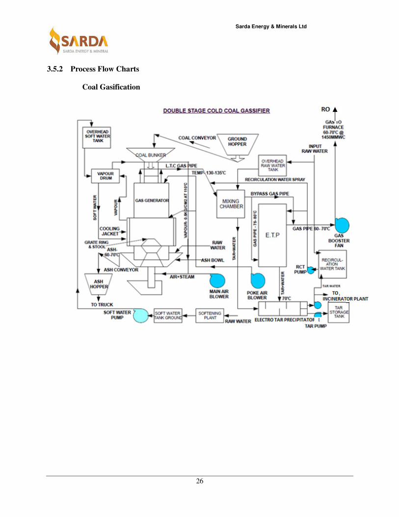
3.5.2 Process Flow Charts
Coal Gasification

Sarda Energy & Minerals Ltd
27
Process Flow Diagram: Iron ore Beneficiation – Proposed
Sarda Energy & Minerals Ltd
28
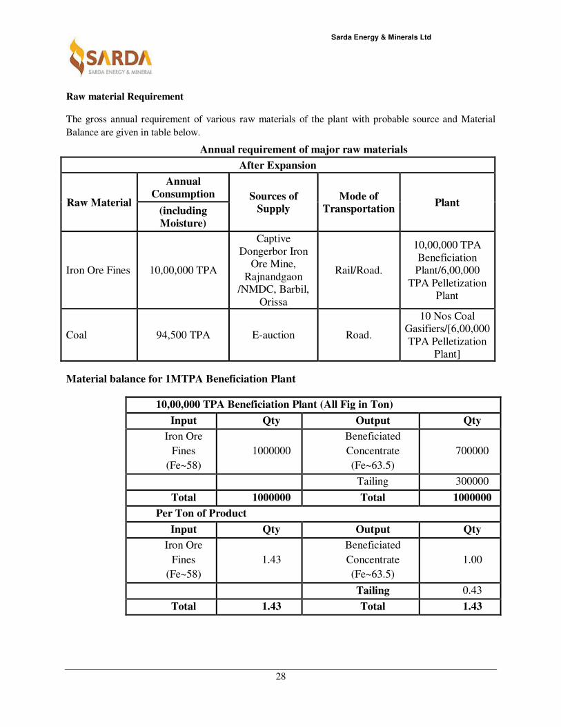
Raw material Requirement
The gross annual requirement of various raw materials of the plant with probable source and Material
Balance are given in table below.
Annual requirement of major raw materials
After Expansion
Raw Material
Annual
Consumption Sources of
Supply
Mode of
Transportation Plant
(including
Moisture)
Iron Ore Fines 10,00,000 TPA
Captive
Dongerbor Iron
Ore Mine,
Rajnandgaon
/NMDC, Barbil,
Orissa
Rail/Road.
10,00,000 TPA
Beneficiation
Plant/6,00,000
TPA Pelletization
Plant
Coal 94,500 TPA E-auction Road.
10 Nos Coal
Gasifiers/[6,00,000
TPA Pelletization
Plant]
Material balance for 1MTPA Beneficiation Plant
10,00,000 TPA Beneficiation Plant (All Fig in Ton)
Input Qty Output Qty
Iron Ore
Fines
(Fe~58)
1000000
Beneficiated
Concentrate
(Fe~63.5)
700000
Tailing 300000
Total 1000000 Total 1000000
Per Ton of Product
Input Qty Output Qty
Iron Ore
Fines
(Fe~58)
1.43
Beneficiated
Concentrate
(Fe~63.5)
1.00
Tailing 0.43
Total 1.43 Total 1.43
Sarda Energy & Minerals Ltd
29
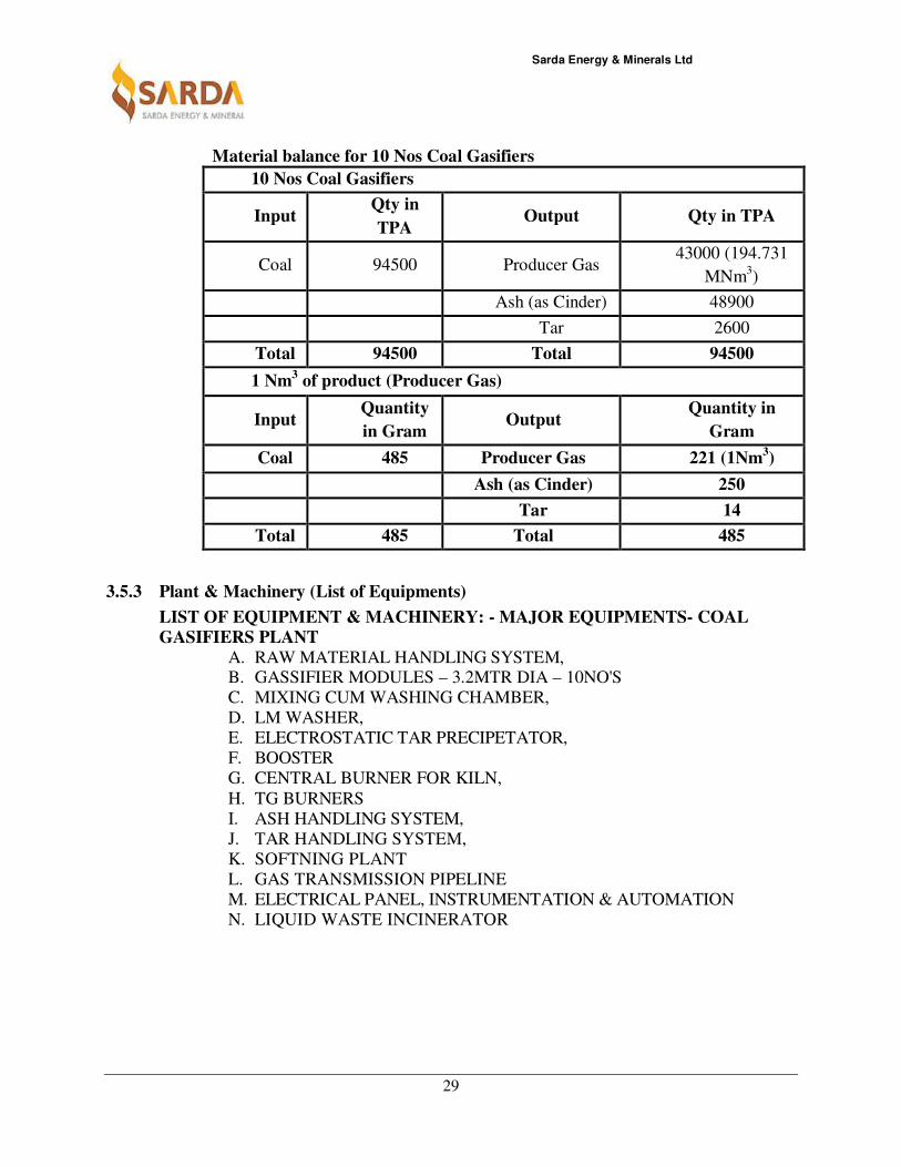
Material balance for 10 Nos Coal Gasifiers
10 Nos Coal Gasifiers
Input Qty in
TPA Output Qty in TPA
Coal 94500 Producer Gas 43000 (194.731
MNm3)
Ash (as Cinder) 48900
Tar 2600
Total 94500 Total 94500
1 Nm3 of product (Producer Gas)
Input Quantity
in Gram Output
Quantity in
Gram
Coal 485 Producer Gas 221 (1Nm3)
Ash (as Cinder) 250
Tar 14
Total 485 Total 485
3.5.3 Plant & Machinery (List of Equipments)
LIST OF EQUIPMENT & MACHINERY: - MAJOR EQUIPMENTS- COAL
GASIFIERS PLANT
A. RAW MATERIAL HANDLING SYSTEM, B. GASSIFIER MODULES – 3.2MTR DIA – 10NO'S
C. MIXING CUM WASHING CHAMBER,
D. LM WASHER,
E. ELECTROSTATIC TAR PRECIPETATOR,
F. BOOSTER
G. CENTRAL BURNER FOR KILN,
H. TG BURNERS
I. ASH HANDLING SYSTEM,
J. TAR HANDLING SYSTEM,
K. SOFTNING PLANT
L. GAS TRANSMISSION PIPELINE
M. ELECTRICAL PANEL, INSTRUMENTATION & AUTOMATION
N. LIQUID WASTE INCINERATOR

Sarda Energy & Minerals Ltd
30
Coal Gasifier Analysis
Total Gasifier 10
Total Coal Required 94500 TPA (485 g/ Nm3)
Make Up Water Required 301m3/Hr
Heat Required 360,000 Kcal/tonne
GCV of the Fuel 1100 Kcal / NM3
Gas Requirement 27,046 Nm3 / Hour
Pellet Output 83.33 T/Hour
Ash Generation 48900 TPA (250 g/ Nm3)
Tar 2600 TPA (14 g/ Nm3)
Water Requirement:
Water is required in the plant is mainly for the purpose of process mixing and equipment
cooling. Water is also required for drinking, sanitary, and fire fighting purposes. In order
to conserve water and minimize the makeup water requirement, it is proposed to adopt
re-circulating systems for equipment cooling. In re-circulating system same water
re-circulates again and again and some make up water is added for evaporation losses.
Requirement
Water
Requirement
(m3/Day)
System
loss
Wastewater
Generation(m3/Day)
Treatment /
Disposal
Methodology
Coal Gasifier Plant:
jacket cooling
and steam
rising
70 50 20
Will be utilized for
Spraining and Dust
Suppression
Ash Pan &
Seal Pots) 167 167 0 --
Gas Gleaning
(Mixing
Chamber &
ETP)
63 61 2 to be incinerated in
an incinerator
Domestic 1 0.5 0.5 Taken to Septic tank
Sarda Energy & Minerals Ltd
31
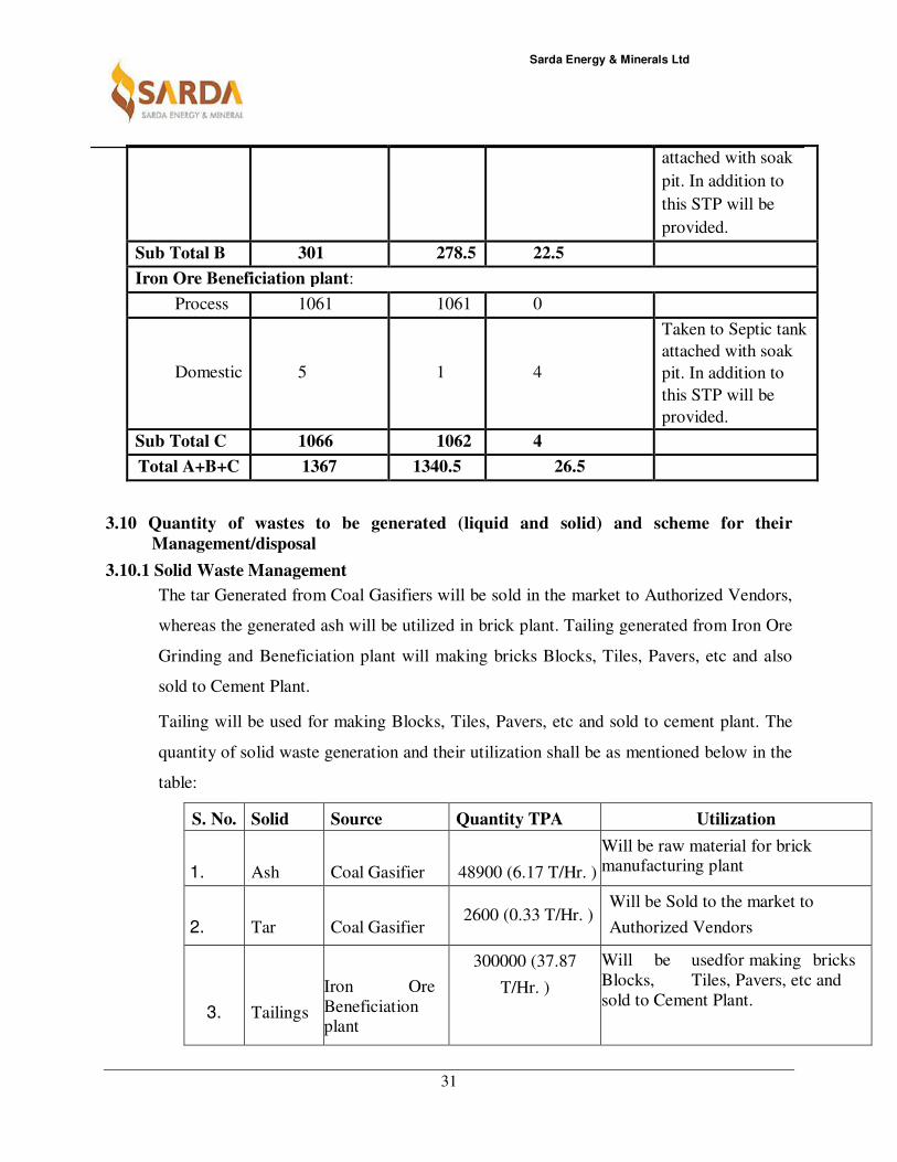
3.10 Quantity of wastes to be generated (liquid and solid) and scheme for their
Management/disposal
3.10.1 Solid Waste Management
The tar Generated from Coal Gasifiers will be sold in the market to Authorized Vendors,
whereas the generated ash will be utilized in brick plant. Tailing generated from Iron Ore
Grinding and Beneficiation plant will making bricks Blocks, Tiles, Pavers, etc and also
sold to Cement Plant.
Tailing will be used for making Blocks, Tiles, Pavers, etc and sold to cement plant. The
quantity of solid waste generation and their utilization shall be as mentioned below in the
table:
S. No. Solid Waste
Source Quantity TPA Utilization
1. Ash Coal Gasifier 48900 (6.17 T/Hr. )
Will be raw material for brick manufacturing plant
2. Tar Coal Gasifier 2600 (0.33 T/Hr. )
Will be Sold to the market to
Authorized Vendors
3. Tailings
Iron Ore
Beneficiation plant
300000 (37.87
T/Hr. )
Will be usedfor making bricks
Blocks, Tiles, Pavers, etc and
sold to Cement Plant.
attached with soak
pit. In addition to
this STP will be
provided.
Sub Total B 301 278.5 22.5
Iron Ore Beneficiation plant:
Process 1061 1061 0
Domestic 5 1 4
Taken to Septic tank
attached with soak
pit. In addition to
this STP will be
provided.
Sub Total C 1066 1062 4
Total A+B+C 1367 1340.5 26.5
Sarda Energy & Minerals Ltd
32
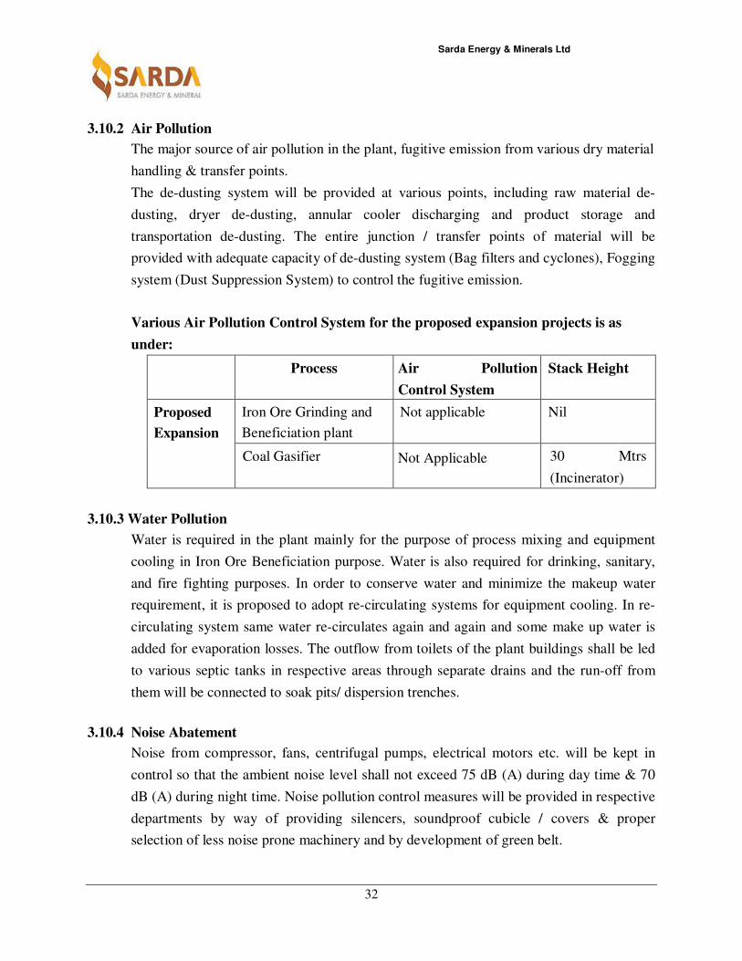
3.10.2 Air Pollution
The major source of air pollution in the plant, fugitive emission from various dry material
handling & transfer points.
The de-dusting system will be provided at various points, including raw material de-
dusting, dryer de-dusting, annular cooler discharging and product storage and
transportation de-dusting. The entire junction / transfer points of material will be
provided with adequate capacity of de-dusting system (Bag filters and cyclones), Fogging
system (Dust Suppression System) to control the fugitive emission.
Various Air Pollution Control System for the proposed expansion projects is as
under:
Process Air Pollution
Control System
Stack Height
Proposed
Expansion
Iron Ore Grinding and
Beneficiation plant
Not applicable Nil
Coal Gasifier Not Applicable 30 Mtrs
(Incinerator)
3.10.3 Water Pollution
Water is required in the plant mainly for the purpose of process mixing and equipment
cooling in Iron Ore Beneficiation purpose. Water is also required for drinking, sanitary,
and fire fighting purposes. In order to conserve water and minimize the makeup water
requirement, it is proposed to adopt re-circulating systems for equipment cooling. In re-
circulating system same water re-circulates again and again and some make up water is
added for evaporation losses. The outflow from toilets of the plant buildings shall be led
to various septic tanks in respective areas through separate drains and the run-off from
them will be connected to soak pits/ dispersion trenches.
3.10.4 Noise Abatement
Noise from compressor, fans, centrifugal pumps, electrical motors etc. will be kept in
control so that the ambient noise level shall not exceed 75 dB (A) during day time & 70
dB (A) during night time. Noise pollution control measures will be provided in respective
departments by way of providing silencers, soundproof cubicle / covers & proper
selection of less noise prone machinery and by development of green belt.
Sarda Energy & Minerals Ltd
33
3.10.5 Plantation/Greenbelt Development
• Total Plant Area is 204.452 ha.
• Approx. 67.4692 ha with 1500 trees/ha is earmarked as greenbelt development
• SEML has already planted 45560 trees in its plant area.
Presently, total plantation at the premises is spread over an area of 30.37 Ha.

Sarda Energy & Minerals Ltd
34
CHAPTER-4
Site Analysis
4.1 Connectivity
The proposed coal Gasifier and of Iron ore Grinding unit to Iron Ore Grinding &
Beneficiation Plant is located at village: Mandhar, Tahsil: Dharsiwa, Dist: Raipur ,
Chhattisgarh State. The nearest city from the site is Raipur which is around 12 KM. The
nearest railway station is Mandhar on Mumbai – Howrah main line which is around 1.5
KM. Nearest air port is at Raipur which is 25 KM from site. The nearby sea port is Vizag
– 500 KM. The site is connected to National Highway-200 which is 5 KM from Site.
4.2 Land Form, Land use and Land ownership
SEML is having 204.452 Ha of industrial land at village Mandhar allotted by
Chhattisgarh State Industrial Development Corporation (CSIDC), Raipur for installation
of 0.6 MTPA pellet plant and 1.1 MTPA Integrated Steel plant (underway Project). The
proposed expansion is within the same premises.
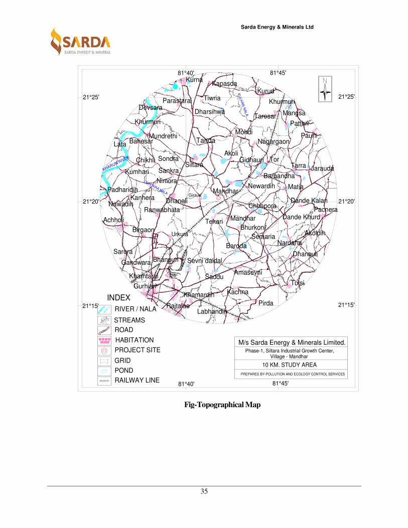
4.3 Topography - with map
The project site is fairly flat with trees/shrubs present at some places. There will not be
much cutting and filling required for the proposed expansion project.
The Topographical map of 10 km radius of the proposed plant site is attached below:
Sarda Energy & Minerals Ltd
35
81°45'
81°40'
81°40'
81°45'
21°25'
21°20'
21°15' 21°15'
21°20'
21°25'
STREAMS
RIVER / NALA
POND
ROAD
HABITATION
GRID
PROJECT SITE
INDEX
RAILWAY LINEPREPARED BY-POLLUTION AND ECOLOGY CONTROL SERVICES
10 KM. STUDY AREA
Phase-1, Siltara Industrial Growth Center, Village - Mandhar
M/s Sarda Energy & Minerals Limited.
A-7
Tanda
SiltaraSondraChikhli
Nimora
Sankra
Dhaneli
Birgaon
Achholi
Nawadih
PadharidihKanhera
Kumhari
BahesarLata
Devsara
Mundrethi
Dharsihwa
Tiwria
KurnaKapasda
Parastarai
AkoliGidhauri
Barbandha
Mandhar
Newardih
Bhurkoni
Semaria
Baroda
Saddu
Sevni daldalBhanpuri
Urkura
Ranwabhata
GiraudMandhar
Matia
Tarra Jarauda
Pauni
PatthriTaresar
Khurmuri
Mangsa
Kurud
Nagargaon
Mohdi
Tor
Dande Kalan
Dande Khurd
Nardaha
Amasevni
Tekari
Sarora
Gandwara
Gurhiari
RajtalaoLabhandih
Pirda
Tulsi
Dhansuli
Akoldih
Pacnera
Khamtarai
Khamardih Kachna
KHARUN RIVER
KU
LH
AN
NA
LA
CHHOKRA NALA
Chhopora
Khurmuri
Fig-Topographical Map
Sarda Energy & Minerals Ltd
36
4.4 Existing land use pattern (agriculture, non-agriculture, forest, water bodies (including
area under CRZ)), shortest distances from the periphery of the project to periphery of
the forests, national park, wild life sanctuary, eco sensitive areas, water bodies
(distance from the HFL of the river), CRZ.
Company is having 204.452 Ha land at Mandhar which is industrial land. The physical
changes in respect of topography and land use, though permanent, shall be compensated by
developing green belt around the project site.
There is no National Park, Wildlife Sanctuaries, and Forests in 10 KM radius from our
existing pellet and ISP site.
Nearby Eco-sensitive zones- Nil
Nearby Elephant/Tiger Reserves-Nil
Migratory Routes- No
4.5 Existing Infrastructure
Good infrastructure is available in the vicinity of Plant; some of the key features are listed
below:
1. Availability of NH-200 which is 5 KM away from proposed expansion project site.
Same can be used for transportation of all kind of Plant Equipment, Raw material etc.
2. SEML is having its own Railway Siding in the existing premises of 1.1 MTPA
Integrated Steel Plant (underway project).
3. Availability of adequate Water Resources.
4. 132 kV/ 33 kV switch yard already exists in the proposed plant premises for taking
electricity supply from CSPDCL. SEML also have facility to take power supply from
our power plant.
4.6 Soil classification
Physical characteristics of soil are delineated through specific parameters viz. particle size
distribution, bulk density, porosity, water holding capacity and texture. The bulk density of
the soil in the site ranged between 1.32 to 1.47 g/cc which indicates favorable physical
condition for plant growth. The porosity and water holding capacity of the soils are in the
range of 26.21 % to 33.27 % and 24.88% to 31.65% respectively. The soil in the impact zone
has clayey structure with moderate water holding capacity.
Sarda Energy & Minerals Ltd
37
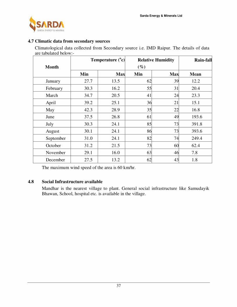
4.7 Climatic data from secondary sources
Climatological data collected from Secondary source i.e. IMD Raipur. The details of data are tabulated below:-
Month
Temperature (oc) Relative Humidity
(%)
Rain-fall
Min Max Min Max Mean
January 27.7 13.5 62 39 12.2
February 30.3 16.2 55 31 20.4
March 34.7 20.5 41 24 23.3
April 39.2 25.1 36 21 15.1
May 42.3 28.9 35 22 16.8
June 37.5 26.8 61 49 193.6
July 30.3 24.1 85 73 391.8
August 30.1 24.1 86 73 393.6
September 31.0 24.1 82 74 249.4
October 31.2 21.5 73 60 62.4
November 29.1 16.0 63 46 7.8
December 27.5 13.2 62 43 1.8
The maximum wind speed of the area is 60 km/hr.
4.8 Social Infrastructure available
Mandhar is the nearest village to plant. General social infrastructure like Samudayik
Bhawan, School, hospital etc. is available in the village.
Sarda Energy & Minerals Ltd
38
CHAPTER- 5
Planning Brief
5.1 Planning concept
Type of industry: Pellet Plant along with coal gasifier and Iron Ore Grinding & Beneficiation
Plant.
Transportation Facilities: National Highway-200 for transportation which is about 5 KM
from Plant site connected by internal roads. Mandhar railway station is about 1.5 KM from
proposed plant site. The Company is having its own Railway Siding in the proposed
expansion premises.
Town and Country planning/Development authority: Gram Panchayat
5.2 Population Projection
Total Population in 10 KM radius of site is estimated as 95022.
5.3 Land use planning (breakup along with green belt etc.)
Company has been allotted 204.452 Hectares of land at village Phase-I of Siltara Industrial
Growth Centre, Mandhar, Raipur for installation of 1.1 MTPA Integrated Steel Plant and
60MW WHRB power plant. Company has been allotted 204.452 Hectares of land at village
Mandhar, Phase-I of Siltara Industrial Growth Centre, Raipur for installation of 1.1 MTPA
Integrated Steel Plant and 60MW WHRB power plant. Out of which 12.04 Ha of land has
been utilized by Pellet Plant along with the proposed expansion of Coal Gasifier and
modernization into Iron Ore Grinding & Beneficiation Plant. About 10.12 out of the above
204.452 Ha has also been earmarked for future expansions. It is located centrally vis-à-vis
source of raw material as well as Sponge Iron consuming industry.
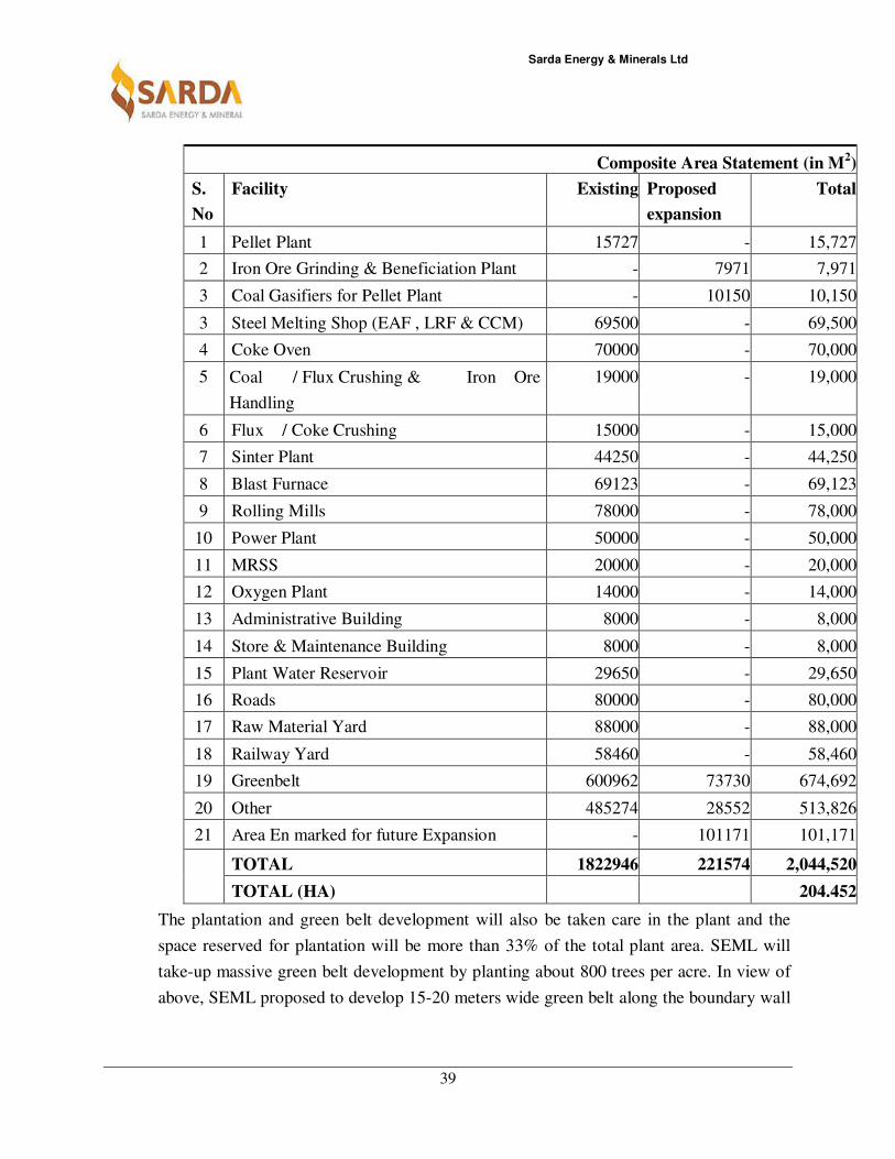
STATEMENT OF AREA
SEML has in possession of 204.452 hectares of Land in Phase-I, Siltara Industrial Growth
Centre, Mandhar, for installation of 1.1 Million TPA Integrated Steel Plant along with
2x30MW WHRB based Power Plant. The details of land area for existing, underway and
proposed expansion projects are shown in table given below:-
Sarda Energy & Minerals Ltd
39
Composite Area Statement (in M2)
S.
No
Facility Existing Proposed
expansion
Total
1 Pellet Plant 15727 - 15,727
2 Iron Ore Grinding & Beneficiation Plant - 7971 7,971
3 Coal Gasifiers for Pellet Plant - 10150 10,150
3 Steel Melting Shop (EAF , LRF & CCM) 69500 - 69,500
4 Coke Oven 70000 - 70,000
5 Coal / Flux Crushing & Iron Ore
Handling
19000 - 19,000
6 Flux / Coke Crushing 15000 - 15,000
7 Sinter Plant 44250 - 44,250
8 Blast Furnace 69123 - 69,123
9 Rolling Mills 78000 - 78,000
10 Power Plant 50000 - 50,000
11 MRSS 20000 - 20,000
12 Oxygen Plant 14000 - 14,000
13 Administrative Building 8000 - 8,000
14 Store & Maintenance Building 8000 - 8,000
15 Plant Water Reservoir 29650 - 29,650
16 Roads 80000 - 80,000
17 Raw Material Yard 88000 - 88,000
18 Railway Yard 58460 - 58,460
19 Greenbelt 600962 73730 674,692
20 Other 485274 28552 513,826
21 Area En marked for future Expansion - 101171 101,171
TOTAL 1822946 221574 2,044,520
TOTAL (HA) 204.452
The plantation and green belt development will also be taken care in the plant and the
space reserved for plantation will be more than 33% of the total plant area. SEML will
take-up massive green belt development by planting about 800 trees per acre. In view of
above, SEML proposed to develop 15-20 meters wide green belt along the boundary wall
Sarda Energy & Minerals Ltd
40
inside the factory premises. Adequate plantation will substantially abate the dust
pollution, filter the polluted air, reduce the noise and ameliorate the plant environment.
5.4 Assessment of Infrastructure Demand (physical & social).
Basic infrastructure demand for nearby area would be first to have internal roads,
availability of clean and pure drinking water, availability of good schools, availability of
Hospitals, community halls, Sulabh Shauchalaya , easy and faster means of transportation
and connectivity to nearby town and city, availability of uninterrupted electricity etc. are
the present assessed demands for sustained and healthy growth of nearby area of site.
Most of the infrastructure demand mentioned above comes automatically when industry
of this magnitude comes in such area, systematic efforts shall be made to bring such
facility in the surrounding area for all round physical and social development.
5.5 Amenities / Facilities
For the social development in the area the company has planned to construct community
halls, roads, provide drinking water etc. Company will provide mobile medical van for
the free treatment for nearby villagers. Time to time the company will also organize free
eye check up, cataract camp, free distribution of spectacles etc.
Sarda Energy & Minerals Ltd
41
CHAPTER-6
Proposed Infrastructure
6.1 Industrial Area
Our existing premises of 6,00,000 pellet plant and 1.1 MTPA ISP (Underway) which is
located at phase-I of Siltara Industrial Growth centre, Village- Mandhar, District- Raipur.
The proposed expansion of 10 Nos Coal Gasifiers along with Modernization of Iron Ore
Grinding Unit to Iron Ore Grinding and Beneficiation Plant is also proposed to be
established in the same premises.
6.2 Green Belt
The plantation and green belt development will also be taken care in the plant and the
space reserved for plantation will be more than 33% of the total plant area. SEML will
take-up massive green belt development by planting about 800 trees per acre. In view of
above, SEML proposed to develop 15-20 meters wide green belt along the boundary wall
inside the factory premises. Adequate plantation will substantially abate the dust
pollution, filter the polluted air, reduce the noise and ameliorate the plant environment.
6.3 Social Infrastructure
For the social development company will provide the arrangement of community hall,
road, water, electricity etc. in the nearby villages. For the economical development the
company will provide the employment as per requirement and individual’s qualification
& eligibility.
6.4 Drinking Water Management
Water for the plant will be supplied from Kharoon River located about 11KM from the
site through water pump, or from rain water harvesting pond of the plant site. The water
system will cater to the drinking and sanitary requirements of plant personnel as well as
laboratory and contingent users. The required water will be withdrawn from the storage
reservoir by two pumps (including one stand-by). The treated water will be chlorinated
and stored in the overhead tank for distribution as drinking water.
Sarda Energy & Minerals Ltd
42
6.5 Sewerage system
It is proposed to collect fecal sewerage through sewerage network from the plant and lead
it to the sewerage treatment plant. The treatment plant shall consist of screen grit
separator, primary sedimentation tank, activated sludge plant, secondary clarifier, sludge
recirculation pump house etc. The treated effluent quality shall confirm to the Indian
Standard for discharge to surface water.
6.6 Industrial Waste Management
Management procedure of all kind of wastes from Plant like Ash & Effluent Water etc is
already discussed in details under point no. 3.10.3 of this report.
Power requirement for 10,00,000 Iron Ore Grinding & Beneficiation Plant & Coal
Gasifier
The total power requirement after expansion for Iron Ore Grinding &
Beneficiation Plant and Coal Gasifiers will be about 5108 KW.

Sarda Energy & Minerals Ltd
43
CHAPTER- 7
Rehabilitation and Resettlement (R & R) Plan
The total land allotted by CSIDC to SEML for the installation of 1.1 MTPA Integrated Steel
Plant (underway) is 204.452 ha. which is industrial land. There was no displacement of people.
Thus R & R issues are not applicable.

Sarda Energy & Minerals Ltd
44
CHAPTER-8
Project Schedule and Cost Estimates
8.1 Likely date of start of construction and likely date of completion:
Expected date of Commercial Production
Proposed expansion 10 Nos Coal
Gasifiers Plant
January 2018
Proposed expansion Iron Ore Grinding
Unit to Iron Ore Grinding &
Beneficiation Plant
January 2018
Project Implementation Concept
In order to ensure coordinated implementation within the short construction period
envisaged for the project, it will be necessary to evolve an optimal compromise between
the fully disaggregated mode and the turnkey package implementation mode. In
principle, it will be prudent to tie up the technology requirements and the key equipment
in the production units to reliable and high quality vendors. In the case of the major
production packages, it will be necessary for the Principal supplier (responsible for the
basic engineering, equipment engineering, technology, critical equipment supply, and
performance guarantees). The local procurement can cover the balance non-critical
equipment, auxiliaries and systems. The major auxiliary packages in the power system,
water system and the yard utilities will be formed into discrete packages.
The proposed model has been adopted in a number of projects with considerable success
and fast ramp up. The construction schedule for the project has been drawn up
accordingly.
Construction Schedule
The schedule has been developed considering mostly the supply of plant and equipment,
as well as volume of work for Construction /Erection of the plant and other local
conditions at site. According to the schedule, worked out, the coal gasifier & iron ore
grinding & beneficiation plant has been planned, to be commissioned within 12 months
from the date of placement of order for the main plant.
Sarda Energy & Minerals Ltd
45
ADVANCE ACTIONS
The project due to its large investment stands to gain substantially if the actual
construction and implementation period is kept to the minimum. For this purpose it is
necessary that the planning and preparatory work on the project be done in a thorough
manner, which will ensure that the project construction and implementation once started
can proceed uninterrupted and without any delays. The start date (Zero date) for the
construction schedule is reckoned as the completion of these advance actions. The
advance actions on the project which will provide the appropriate foundation for cost
effective and timely implementation are:
i) Environmental clearance for implementation of the project
ii) Finalization of the financing arrangements for the project and the creation of a
project organization
iii) Finalization of the adequate details of the project to enable site activities to
commence from the date of ‘go-ahead’.
iv) Issue of inquiries for the major packages and finalization of the orders for the
same.
vii) Actions for linkages of power, water and other infrastructure.
SITE DEVELOPMENT & CONSTRUCTIONS FACILITIES
Site development activities include contour survey, soil investigation, site preparation,
site drainage, construction water, construction power, construction storage yards etc.
Activities related to site acquisition surveys and soil investigations will envisage to be
accomplished by the time the ‘go-ahead’ for project commences. Establishment of
construction power, water site preparation and other activities will be completed in three
(3) months from ‘go-ahead’.
Special efforts will have to be made during implementation to keep the earthwork and the
site preparation to the minimum both for cost savings as well as reduction in construction
time.
CIVIL & STRUCTURAL WORK
The schedule for carrying out the civil work and structural steel work is based on the
volume of work and interlink between the completions of some of these activities to
Sarda Energy & Minerals Ltd
46
enable the subsequent activities to proceed. Structural steelwork covers all the building
structures. In order to meet the overall time-frame envisaged in the schedule, the
completion of civil and structural work in a time-bound manner is a pre-requisite for the
project completion for the schedule.
EQUIPMENT MANUFACTURE & DELIVERY
As indicated earlier, as an advance action, enquiries will have to be issued for the various
plant and equipment, on a global basis, tenders evaluated and orders finalized. Major
packages will cover material handling system, Beneficiation Plant, Gasifiers and these will
need to be tendered out. Placement of order for such packages is envisaged within two (2)
months to seven (7) months from the date of go ahead for project construction. It is
assumed that advance work on the preparation of specifications, evaluation of tenders and
readiness for placement of orders will be taken parallely with the land acquisition process
and the project preliminaries. The duration generally accepted internationally for
manufacture and delivery of various equipments have been taken into account while
evolving the implementation schedule.
EQUIPMENT ERECTION
Erection of equipment will have to commence after availability of fronts on completion
of the civil and structural work as well as delivery of equipment at the plant site. It is
expected that the duration for erection of equipment for the various plant facilities will
vary between Six (6) months to Eight (8) months from the date of commencement of
equipment erection.
EXTERNAL FACILITIES
The various off site facilities such as external water supply, external power supply and
rail transportation links, road links etc are already available in our existing premises
where the expansion of project is proposed.
TRIAL RUNS & COMMISSIONING
Commissioning work will be done after completion of Erection work. A period of 6
months has been envisaged for carrying out commissioning work and trial runs.
Sarda Energy & Minerals Ltd
47
Project Monitoring
At the project implementation stage, all project activities from design and engineering to
construction, equipment supply, erection, testing and commissioning of the plant and
equipment will be monitored on the basis of a computerized network monitoring system.
Various reports as relevant for different aspects of project monitoring will be generated
through the computerized system.
Action points will be identified agency-wise and actions taken for timely implementation
the milestones to be achieved for meeting this schedule will be identified and monitored for
their achievement. Critical activities of the project as they arise will also be identified and
monitored and followed up to ensure timely completion.
8.2 Estimated project cost along with analysis in terms of economic viability of the
project
Since the report includes a project which is already under operation the Cost of Project.
Thus, for the established unit the Gross Capital Made has been considered as Cost of
project and for the other two it is estimated based on enquiries floated, quotations
received. The financing and pre-operative cost has been considered based on the
proposed financial package.
The estimated cost thus evaluated to be is Rs 12.789 Crores including pre-operative
expenses and margin money for working capital requirements
Cost of Capital
All Fig Lac Rs
Sl No Particular Amount
1 Iron Ore Grinding & Beneficiation Plant 8202
2 10 NO Coal Gasifier 4587
# Total 12789
Sarda Energy & Minerals Ltd
48
CHAPTER-9
Analysis of proposal (Final Recommendations)
9.1 Financial and social benefits with special emphasis on the benefits to the local people
including tribal population
The pellet plant already exists, However, the proposed expansion project will result in
improvement of infrastructure as well as upliftment of social structure in the area. The people
residing in the nearby areas will be benefited directly and indirectly. It is anticipated that the
proposed plant will provide benefits for the local people in two phases i.e. during
construction phase as well as during operational stage of the plant.
• Construction Phase
Employment
The major benefit due to the proposed expansion project will be in the sphere of
generating employment for people of that area. The proposed expansion project will
benefit local population.
• Operational Phase
Community Services
SEML will employ local people to the extent possible for avoiding creation of additional
infrastructure. SEML will develop medical facilities for catering to the needs of the
project personnel. These facilities will also be extended to the local community in due
course.
Education
SEML will initiate action for social upliftment in the area like female education,
vocational training. Financial support will also be extended to strength education
infrastructure in the region.
Transportation
There will also be small increase in the vehicular traffic due to passenger transport. This
increase in traffic will not have any consequence to warrant special mention. One should
expect that the increased passenger load in the sector would prompt the state
Sarda Energy & Minerals Ltd
49
government/ private movers to start new and frequent public transport services to this
area, bringing upliftment to the whole locality.
Other Benefits
SEML is equally conscious for the all round socio-economic development and is
committed to raise the quality of life and social well being of communities where it
operates. Its CSR initiatives have been prioritized on local needs, which focus on Health,
Education, Infrastructure Development and Environment Conservation.
Related Documents